EP2602132B1 - Draw bar with a positioning drive assembly - Google Patents
Draw bar with a positioning drive assemblyDownload PDFInfo
- Publication number
- EP2602132B1 EP2602132B1EP12007931.4AEP12007931AEP2602132B1EP 2602132 B1EP2602132 B1EP 2602132B1EP 12007931 AEP12007931 AEP 12007931AEP 2602132 B1EP2602132 B1EP 2602132B1
- Authority
- EP
- European Patent Office
- Prior art keywords
- coupling
- trailer
- arm
- receptacle
- locking
- Prior art date
- Legal status (The legal status is an assumption and is not a legal conclusion. Google has not performed a legal analysis and makes no representation as to the accuracy of the status listed.)
- Active
Links
- 230000008878couplingEffects0.000claimsdescription240
- 238000010168coupling processMethods0.000claimsdescription240
- 238000005859coupling reactionMethods0.000claimsdescription240
- 238000000034methodMethods0.000claimsdescription3
- 238000004891communicationMethods0.000description9
- 230000005540biological transmissionEffects0.000description6
- 238000001514detection methodMethods0.000description3
- 230000001953sensory effectEffects0.000description3
- 238000010586diagramMethods0.000description2
- 230000003287optical effectEffects0.000description2
- 230000004913activationEffects0.000description1
- 230000000903blocking effectEffects0.000description1
- 238000002485combustion reactionMethods0.000description1
- 230000007613environmental effectEffects0.000description1
- 230000006870functionEffects0.000description1
- 238000005259measurementMethods0.000description1
- 238000012544monitoring processMethods0.000description1
- 230000011664signalingEffects0.000description1
- 230000006641stabilisationEffects0.000description1
Images

Classifications
- B—PERFORMING OPERATIONS; TRANSPORTING
- B60—VEHICLES IN GENERAL
- B60D—VEHICLE CONNECTIONS
- B60D1/00—Traction couplings; Hitches; Draw-gear; Towing devices
- B60D1/01—Traction couplings or hitches characterised by their type
- B60D1/06—Ball-and-socket hitches, e.g. constructional details, auxiliary devices, their arrangement on the vehicle
- B—PERFORMING OPERATIONS; TRANSPORTING
- B60—VEHICLES IN GENERAL
- B60D—VEHICLE CONNECTIONS
- B60D1/00—Traction couplings; Hitches; Draw-gear; Towing devices
- B60D1/24—Traction couplings; Hitches; Draw-gear; Towing devices characterised by arrangements for particular functions
- B60D1/246—Traction couplings; Hitches; Draw-gear; Towing devices characterised by arrangements for particular functions for actuating the hitch by powered means
- B—PERFORMING OPERATIONS; TRANSPORTING
- B60—VEHICLES IN GENERAL
- B60D—VEHICLE CONNECTIONS
- B60D1/00—Traction couplings; Hitches; Draw-gear; Towing devices
- B60D1/24—Traction couplings; Hitches; Draw-gear; Towing devices characterised by arrangements for particular functions
- B60D1/36—Traction couplings; Hitches; Draw-gear; Towing devices characterised by arrangements for particular functions for facilitating connection, e.g. hitch catchers, visual guide means, signalling aids
- B—PERFORMING OPERATIONS; TRANSPORTING
- B60—VEHICLES IN GENERAL
- B60D—VEHICLE CONNECTIONS
- B60D1/00—Traction couplings; Hitches; Draw-gear; Towing devices
- B60D1/24—Traction couplings; Hitches; Draw-gear; Towing devices characterised by arrangements for particular functions
- B60D1/42—Traction couplings; Hitches; Draw-gear; Towing devices characterised by arrangements for particular functions for being adjustable
- B60D1/46—Traction couplings; Hitches; Draw-gear; Towing devices characterised by arrangements for particular functions for being adjustable vertically
- B60D1/465—Traction couplings; Hitches; Draw-gear; Towing devices characterised by arrangements for particular functions for being adjustable vertically comprising a lifting mechanism, e.g. for coupling while lifting
- B—PERFORMING OPERATIONS; TRANSPORTING
- B60—VEHICLES IN GENERAL
- B60D—VEHICLE CONNECTIONS
- B60D1/00—Traction couplings; Hitches; Draw-gear; Towing devices
- B60D1/48—Traction couplings; Hitches; Draw-gear; Towing devices characterised by the mounting
- B60D1/54—Traction couplings; Hitches; Draw-gear; Towing devices characterised by the mounting collapsible or retractable when not in use, e.g. hide-away hitches
- B—PERFORMING OPERATIONS; TRANSPORTING
- B60—VEHICLES IN GENERAL
- B60D—VEHICLE CONNECTIONS
- B60D1/00—Traction couplings; Hitches; Draw-gear; Towing devices
- B60D1/58—Auxiliary devices
- B60D1/62—Auxiliary devices involving supply lines, electric circuits, or the like
Definitions
- the inventionrelates to a trailer coupling with a arranged on a motor vehicle or can be arranged holder on which a coupling arm is movably mounted with a coupling element for engagement in a coupling receptacle of a coupling of a trailer by means of a bearing assembly according to the preamble of claim 1.
- the coupling armis adaptable to different heights, so that, for example, depending on the load condition of the trailer or the towing vehicle of the coupling arm can be adjusted.
- the handling of known towbarsis complicated, that is, first, the height of the coupling element must be adjusted before the trailer can be coupled.
- the bearing arrangement of a trailer coupling according to the inventionhas degrees of freedom of movement about at least two axes of rotation and / or about at least one axis of rotation and a sliding axis.
- the inventionprovides that the coupling arm is movably mounted by means of the bearing arrangement between the use position as well as a non-use position.
- the coupling armis adjusted in the non-use position towards the vehicle, for example, hidden behind a bumper back adjusted.
- the bearing assemblynot only has the function to position the coupling element, in particular a coupling ball, in one embodiment of the invention in or in the coupling receptacle of the trailer, but advantageously allows the coupling arm when not in use to adjust so that he does not more bothers, in particular the ground clearance of the motor vehicle is not hindered.
- motor vehiclefor example, a passenger car, for example, with an internal combustion engine and / or an electric motor to include.
- the bearing arrangementmay of course comprise various types of bearings, for example at least one linear bearing and / or at least one ball bearing and / or at least one pivot bearing or the like. It is understood that other bearing concepts of the bearing assembly, such as sliding bearing and / or pivot sliding bearing and / or at least one pivot bearing, in particular a plurality of pivot bearing with mutually angular axes of rotation, and / or gimbals or the like are readily possible.
- a self-contained inventionit represents when the coupling arm is multi-part and has a bearing arrangement with the vehicle mount movably mounted first Kupplungsarmabites on which by means of a Kupplungsarmlagers a second Kupplungsarmabites is movably mounted. It is understood that other Kupplungsarmabitese or Kupplungsarmsegmente are possible.
- the positioning drive arrangementexpediently comprises at least one drive assigned to the coupling arm bearing, for example an electric direct drive, a transmission or the like, so that the second and further coupling arm section is motor-adjustable with respect to the coupling arm section on which it is movably mounted.
- a respective coupling arm portionmay be straight and / or have bends.
- the bearing arrangement provided on the holder and the at least one coupling arm bearingare configured such that the coupling element can be introduced by the positioning drive arrangement essentially perpendicular to an upper apex plane of the coupling receptacle. It can also be said that the coupling element can be inserted as vertically as possible from below into the coupling receptacle. This makes it possible that the coupling element is optimally inserted into the coupling receptacle, that it is securely locked there and / or not tilted.
- the trailer couplinghas a locking device for locking the coupling arm, at least in the position of use, preferably also in the aforementioned non-use position.
- the locking deviceexpediently comprises one or more locking elements, which engage in a locking position in the locking opening on the coupling arm and / or on the holder and thus lock the coupling arm.
- the at least one locking elementcan be actuated, for example, by a locking drive into the locking position and / or from the locking position into a release position in which the coupling arm is movable.
- the at least one locking elementis loaded by a spring arrangement at least in the locking position. This means that the locking element almost automatically locked, even if no operation, for example, by an operator or the aforementioned locking drive, is present.
- the sensor arrangementcomprises a sensor arranged on the coupling arm, in particular on the coupling element.
- the sensormay include an RFID reader to detect if the coupling element is in the coupling receptacle. In this way, it is even detectable whether the hitch is to be coupled to a trailer for which it is approved. This can also serve as a security measure. If, for example, measures are also taken at the trailer-side coupling which facilitate an automatic coupling, it can be ensured via an RFID transponder on the trailer-side coupling that only suitable trailers are coupled to the trailer coupling according to the invention.
- the positioning drive assemblysuitably has sufficient force to then move the coupling arm to the position of use, e.g. to turn up and down and / or to push while taking the coupling of the trailer.
- This coupling of the traileris raised or lowered, for example. It is also possible for the towing vehicle to move slowly during this process.
- a self-contained innovative conceptis when the control device so long as the positioning of the coupling element in the direction of the coupling recording drives, for example by continuous energization of a drive motor, but also by repetition cycles or "night acts", for example repeated energization of the drive motor, even if the coupling element already fully engages in the coupling receptacle, that is, in itself the coupling between towing vehicle and trailer is given, but the coupling arm has not yet taken the position of use. This may for example be the case when the coupling receptacle is lower than the position of the coupling element in its position of use. In this way can be effected, for example, the aforementioned Locking device actually locked, especially when the at least one locking element is spring-loaded in the locking position.
- the control unitis expediently designed to send a control signal to the motor vehicle, for example to a vehicle electrical system.
- the control signalinstructs the motor vehicle, for example, to drive slowly until the clutch arm reaches the position of use as a result of the further activation of the positioning drive arrangement.
- the motor vehiclethus still drives very slowly, while the positioning drive arrangement adjusts the coupling arm until it reaches the position of use.
- the positioning drive arrangementadjusts the coupling arm until it reaches the position of use.
- the teamis unfavorable, it may otherwise be that the remaining in place combination of motor vehicle and trailer the Positionierantrieban Aunt quasi blocked or whose force is insufficient to the coupling arm against the forces acting on him, in the direction of To adjust the position of use, for example, engages the locking of the coupling arm.
- the control unitis expediently designed to output at least one signaling signal and / or at least one control signal to the motor vehicle.
- the controllerhas a bus interface or other interface to communicate with the electrical system of the motor vehicle.
- a hitch 10is attached, for example, to a rear cross member 91 of a motor vehicle 90.
- a holder 11 of the trailer coupling 10comprises retaining elements 12, 13 which are not described here in more detail, which are fastened to the rear cross member 91, for example welded or screwed on.
- the holder 11further comprises a bearing assembly 14, which comprises, for example, a ball bearing 20 or a functioning bearing in the manner of a ball bearing.
- the bearing arrangement 14includes a quasi-vehicle-side bearing part 15, which is connected to the mount 11 and engages in a bearing receptacle 16 of a bearing part 17.
- the bearing part 17carries a coupling arm 18 which projects from the bearing part 17.
- the vehicle-side bearing part 15is, for example, outside spherical, while the bearing receptacle 16 is configured in the manner of a hollow sphere.
- a bearing part 17 'which carries the coupling arm 18, also in one the vehicle-side bracket 11 'arranged bearing receptacle 16' may be stored.
- the coupling arm 18carries at its free end portions remote from the bearing part 17 a coupling element 19, for example a coupling ball. It is understood that other types of coupling elements, such as polygonal coupling elements, are possible.
- the coupling arm 18can by means of the bearing assembly 14 between a in FIG. 1 in solid lines as well as in FIG. 2a shown use position G over several intermediate positions, of which exemplary intermediate positions Z1 and Z2 are shown, are adjusted to a non-use position N, in which the coupling arm 18 is substantially hidden close to the motor vehicle 90, in particular its body is.
- the clutch arm 18 in the non-use position N behind a bumper 94 of the motor vehicle 90is moved back so that it is not visible from the back above.
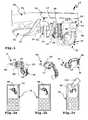
- the coupling arm 18can be locked by means of a locking device 21 in its position of use G and the non-use position N.
- a locking element 22for example a locking pin, engages in a locking position that is in FIG. 4 is shown in a locking receptacle or locking opening 23 on the bearing part 17 or acts on shaped pieces 24, for example balls, so that they engage in one or more locking openings 23 on the bearing part 17.
- the locking element 22is acted upon by a spring 25 in the locking position.
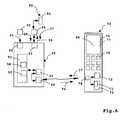
- the positioning drive assembly 27is controlled by a control unit 50, of which a block diagram in FIG. 6 shown is.
- the control unit 50is suitably encapsulated and / or arranged in a housing, so that it is protected from environmental influences.
- the control unit 50has, for example, a microprocessor 52 and a memory 53, the microprocessor 52 programs stored in the memory 53, for example a positioning program 54 for positioning the coupling arm 18 and a communication program 55 for communication with a vehicle electrical system 93 of the motor vehicle 90 can.
- control unit 50advantageously receives speed information 57 from the on-board network 93, so that it only activates the positioning drive arrangement 27 for adjusting the coupling arm 18 when the motor vehicle 90 is stationary or, at best, traveling slowly. This will become clear later.
- a communicationis appropriate, for example, to send a blocking signal 58 to the electrical system 93, namely that, for example, an electronic stabilization program or an engine control unit 95 only allows driving of the motor vehicle 90, when the hitch 10 assumes its position of use G.
- the control unit 50additionally has a sensor interface 62 for communication with a sensor 30, for example an RFID reading device, so that the control unit 50 can receive a sensor signal 33 from the sensor 30.
- the hitch 10allows automatic coupling to a coupling 81 of a trailer 80
- the coupling 81is shown substantially schematically and includes, for example, a coupling receptacle 82, in which the coupling element 19 engages in a coupling position, so that a known ball-joint bearing the coupling receptacle 82nd given at the coupling element 19.
- the positioning workis much easier in the trailer coupling according to the invention, namely, since the control unit 50, the positioning drive assembly 27 controls so that the coupling element 19 as it finds itself in the coupling receptacle 82.
- the detectionis made such that an RFID transponder 83 is arranged on the coupling 81, preferably on the coupling receptacle 82, in particular on its upper vertex, which can be located and determined by the sensor 30.
- the sensor 30detects a signal strength of the RFID transponder 83 to determine its position.
- an operating concept with an external operating device 70such as a mobile phone, smartphone or the like conceivable that via an operating device interface 64, such as a radio interface (wired communication is alternatively possible), communicates with the controller 50 to ultimately the Positioning drive assembly 27 for positioning of the coupling element 18 in the coupling receptacle 82 to control.
- an operating device interface 64such as a radio interface (wired communication is alternatively possible)
- control commands to a control program 71 of the operating device 70can be given on a graphical user interface 76 and / or by means of input means 75, for example buttons or the like.
- the control program 71is stored, for example, in a memory 73 of the operating device 70 and can be executed by a microprocessor 72.
- the operating device 70then communicates with the control device 50 via a communication interface 74, for example wirelessly.
- the communication interface 74includes, for example, a WLAN interface, a Bluetooth interface or the like.
- the operating device 70then sends control commands 77 generated by the control program 71 to the control device 50, which actuates the positioning drive arrangement 27 in accordance with the instructions thus obtained in such a way that it pivots the coupling arm 18 about the axes D1, D2 and D3.
- the user interface 76is a graphical user interface, i. for example, it is configured to display a symbol 84 of the coupling arm 18 which represents its position in reality.
- the control unit 50notifies, for example, the respective position of the coupling arm 18 to the operating device 70, which tracks the position of the icon 84 accordingly, so that the operator sees where the coupling arm 18 is straight.
- the operatorcan preselect or influence the respective position of the coupling arm 18 by means of his finger 100. To do this, the operator merely has to guide the finger 100 over a screen 78 of the operating device 70.
- control unit 50virtually monitors the locking of the coupling arm 18 and possibly the positioning drive arrangement 27 for readjustment of the coupling arm 18 in the direction of the use position G drives until the use position G is reached.
- the coupling element 19is indeed already fully received in the coupling receptacle 82, which, for example, can be sensed, for example by means of the sensor 30. Even the locking of the coupling 81 can already be completed. However, it is possible due to, for example, an unfavorable position of the combination consisting of motor vehicle 90 and trailer 80, that the position of use G then not yet reached.
- the positioning drive assembly 27then receives instructions from the control unit 50 to readjust in the direction of the use position G.
- control unit 50advantageously transmits via the vehicle electrical system communication interface 63 an instruction, that is to say a control signal 59, to the vehicle electrical system 93, initially only to drive slowly until the use position G is reached. It is also possible that the control unit 50 still monitors a time window, i. that, for example, only a short time of a slow drive of the motor vehicle is even possible. Then, when the coupling arm 18 is still not in the use position G, the control unit 50 sends a hold command to the electrical system 93, so that the motor vehicle 90 stops.
- a sensory monitoring of the locking of the locking device 21is appropriate, that is, for example, the control unit 50 only then a driving operation of the motor vehicle 90 releases (for example via the electrical system communication interface 63 when the locking device 21 is in the locked position
- FIG. 5 illustrated coupling arm 118 of a trailer coupling 110is in several parts and comprises a Kupplungsarmabêt 40 and a Kupplungsarmabrough 41, at its free end a coupling element 19 is arranged.
- the coupling arm portion 40is movably supported by a bearing assembly 114 on a bracket 111.
- the coupling arm portion 41is movably mounted on the coupling arm portion 40 by means of a coupling arm bearing 42, eg a pivot bearing, in particular a ball bearing or a pivot bearing.
- the coupling arm 118can be positioned in the coupling receptacle 82.
- the positioning drive assembly 127includes a drive 128 associated with a pivot bearing 120 of the bearing assembly 114, e.g. is arranged there directly and / or acts via a gear between the parts 111 and 40, and the clutch arm 40 relative to the bracket 111 adjusted.
- the coupling arm bearing 42is associated with an arm drive 43, which adjusts the Kupplungsarmabêt 41 relative to the Kupplungsarmabites 40.
- An arrow 44is intended to indicate that in addition to the pivot bearing 20 and the Kupplungsarmlager 42 also more bearings can be provided on the bracket 111 for the coupling arm 118, z. B. a linear bearing for adjusting the coupling arm 118 in the vehicle transverse direction.
Landscapes
- Engineering & Computer Science (AREA)
- Transportation (AREA)
- Mechanical Engineering (AREA)
- Arrangement And Mounting Of Devices That Control Transmission Of Motive Force (AREA)
- Control Of Driving Devices And Active Controlling Of Vehicle (AREA)
- Motor Power Transmission Devices (AREA)
- Lock And Its Accessories (AREA)
Description
Translated fromGermanDie Erfindung betrifft eine Anhängekupplung mit einer an einem Kraftfahrzeug angeordneten oder anordenbaren Halterung, an der ein Kupplungsarm mit einem Kuppelelement zum Eingriff in eine Kupplungsaufnahme einer Kupplung eines Anhängers mittels einer Lageranordnung beweglich gelagert ist gemäß dem Oberbegriff des Anspruchs 1.The invention relates to a trailer coupling with a arranged on a motor vehicle or can be arranged holder on which a coupling arm is movably mounted with a coupling element for engagement in a coupling receptacle of a coupling of a trailer by means of a bearing assembly according to the preamble of claim 1.
Eine derartige Anhängekupplung geht aus
Aus
Es ist daher die Aufgabe der vorliegenden Erfindung, eine einfach handhabbare Anhängekupplung bereitzustellen, die bequem mit einer Kupplung eines Anhängers verbunden werden kann, insbesondere einer so genannten Zugkugelkupplung.It is therefore the object of the present invention to provide an easily manageable trailer coupling, which can be conveniently connected to a coupling of a trailer, in particular a so-called ball coupling.
Zur Lösung der Aufgabe ist eine Anhängekupplung gemäß der technischen Lehre des Anspruchs 1 vorgesehen.To solve the problem, a trailer coupling according to the technical teaching of claim 1 is provided.
Es ist auch vorteilhaft, wenn die Lageranordnung einer erfindungsgemäßen Anhängekupplung Bewegungsfreiheitgrade um mindestens zwei Drehachsen und/oder um mindestens eine Drehachse und eine Schiebeachse aufweist.It is also advantageous if the bearing arrangement of a trailer coupling according to the invention has degrees of freedom of movement about at least two axes of rotation and / or about at least one axis of rotation and a sliding axis.
Es ist ein Grundgedanke der vorliegenden Erfindung, dass mittels der Lageranordnung der Kupplungsarm nicht nur in eine einzige Gebrauchsstellung gebracht werden kann, sondern auch innerhalb eines Stellbereichs um die Gebrauchsstellung herum, beispielsweise nach oben oder unten (in Z-Richtung) und/oder quer dazu (in Y-Richtung), eventuell auch in Fahrzeuglängsrichtung (in X-Richtung) verstellbar ist, so dass das Kuppelelement, zum Beispiel eine Kupplungskugel, in die Kupplungsaufnahme hinein positionierbar ist. Das muss der Bediener jedoch nicht von Hand tun, sondern er wird durch die Positionierantriebanordnung unterstützt, die den Kupplungsarm so positioniert, dass er in die Kupplungsaufnahme hinein gelangt.It is a basic idea of the present invention that by means of the bearing arrangement the coupling arm can not only be brought into a single position of use, but also within an adjustment range around the position of use, for example upwards or downwards (in the Z direction) and / or transversely thereto (in the Y direction), possibly also in the vehicle longitudinal direction (in the X direction) is adjustable, so that the coupling element, for example, a coupling ball, in the coupling receptacle is positioned inside. However, the operator does not have to do this by hand, but is assisted by the positioning drive assembly which positions the coupling arm to enter the coupling receptacle.
Zwar wäre es prinzipiell bei einer Variante der Erfindung möglich, dass die Positionierantriebanordnung einen oder mehrere manuelle Antriebe, beispielsweise eine Kurbel und/oder einen Seilzug oder dergleichen umfasst. Bevorzugt ist jedoch ein motorisches Konzept, bei dem die Positionierantriebanordnung einen oder mehrere Motoren, beispielsweise Elektromotoren, pneumatische Antriebe, hydraulische Antriebe oder dergleichen andere fluidische Antriebe umfasst. Die Positionierantriebanordnung kann selbstverständlich auch eines oder mehrere Getriebe, beispielsweise Zahnradgetriebe, Seilzuggetriebe, Keilgetriebe oder dergleichen, einen Reibradantrieb oder dergleichen umfassen. Weiterhin kann ein Antriebsmotor der Positionierantriebanordnung über eine Getriebeanordnung mehrere Antriebsachsen antreiben.Although it would be possible in principle in a variant of the invention that the positioning drive arrangement comprises one or more manual drives, such as a crank and / or a cable or the like. However, a motor concept is preferred in which the positioning drive arrangement comprises one or more motors, for example electric motors, pneumatic drives, hydraulic drives or the like, other fluidic drives. Of course, the positioning drive arrangement may also include one or more transmissions, for example, gear transmissions, cable transmissions, wedge gears or the like, a friction wheel drive or the like. Furthermore, a drive motor of the positioning drive arrangement can drive a plurality of drive axles via a gear arrangement.
Die Erfindung sieht vor, dass der Kupplungsarm mittels der Lageranordnung beweglich zwischen der Gebrauchsstellung sowie auch einer Nichtgebrauchsstellung gelagert ist. Der Kupplungsarm ist in der Nichtgebrauchsstellung zum Fahrzeug hin verstellt, beispielsweise verborgen hinter einen Stoßfänger zurück verstellt. Somit hat also die Lageranordnung nicht nur die Funktion, das Kuppelelement, insbesondere eine Kupplungskugel, in einer Ausgestaltung der Erfindung in der oder in die Kupplungsaufnahme des Anhängers zu positionieren, sondern ermöglicht in vorteilhafter Weise, den Kupplungsarm bei Nichtgebrauch so zu verstellen, dass er nicht mehr stört, insbesondere die Bodenfreiheit des Kraftfahrzeugs nicht behindert.The invention provides that the coupling arm is movably mounted by means of the bearing arrangement between the use position as well as a non-use position. The coupling arm is adjusted in the non-use position towards the vehicle, for example, hidden behind a bumper back adjusted. Thus, therefore, the bearing assembly not only has the function to position the coupling element, in particular a coupling ball, in one embodiment of the invention in or in the coupling receptacle of the trailer, but advantageously allows the coupling arm when not in use to adjust so that he does not more bothers, in particular the ground clearance of the motor vehicle is not hindered.
An dieser Stelle sei bemerkt, dass der Begriff Kraftfahrzeug beispielsweise einen Personenkraftwagen, zum Beispiel mit einem Verbrennungsmotor und/oder einem Elektromotor, umfassen soll.It should be noted at this point that the term motor vehicle, for example, a passenger car, for example, with an internal combustion engine and / or an electric motor to include.
Bevorzugt umfasst die Lageranordnung mindestens ein Kugellager oder wird durch ein Kugellager gebildet.Die Lageranordnung kann selbstverständlich verschiedenartige Lager umfassen, beispielsweise mindestens ein Linearlager und/oder mindestens ein Kugellager und/oder mindestens ein Schwenklager oder dergleichen. Es versteht sich, dass auch andere Lagerkonzepte der Lageranordnung, beispielsweise Schiebelager und/oder Schwenk-Schiebelager und/oder mindestens ein Drehlager, insbesondere mehrere Drehlager mit zueinander winkeligen Drehachsen, und/oder kardanische Lagerungen oder dergleichen ohne weiteres möglich sind.The bearing arrangement may of course comprise various types of bearings, for example at least one linear bearing and / or at least one ball bearing and / or at least one pivot bearing or the like. It is understood that other bearing concepts of the bearing assembly, such as sliding bearing and / or pivot sliding bearing and / or at least one pivot bearing, in particular a plurality of pivot bearing with mutually angular axes of rotation, and / or gimbals or the like are readily possible.
Eine an sich eigenständige Erfindung stellt es dar, wenn der Kupplungsarm mehrteilig ist und einen mit der Lageranordnung an der Fahrzeug-Halterung beweglich gelagerten ersten Kupplungsarmabschnitt aufweist, an dem mittels eines Kupplungsarmlagers ein zweiter Kupplungsarmabschnitt beweglich gelagert ist. Es versteht sich, dass auch weitere Kupplungsarmabschnitte oder Kupplungsarmsegmente möglich sind. Die Positionierantriebanordnung umfasst zweckmäßigerweise mindestens einen dem Kupplungsarm-Lager zugeordneten Antrieb, zum Beispiel einen elektrischen Direktantrieb, ein Getriebe oder dergleichen, so dass der zweite und weitere Kupplungsarmabschnitt bezüglich des Kupplungsarmabschnitt, an dem er beweglich gelagert ist, motorisch verstellbar ist. Ein jeweiliger Kupplungsarmabschnitt kann gerade verlaufen und/oder Krümmungen aufweisen.A self-contained invention it represents when the coupling arm is multi-part and has a bearing arrangement with the vehicle mount movably mounted first Kupplungsarmabschnitt on which by means of a Kupplungsarmlagers a second Kupplungsarmabschnitt is movably mounted. It is understood that other Kupplungsarmabschnitte or Kupplungsarmsegmente are possible. The positioning drive arrangement expediently comprises at least one drive assigned to the coupling arm bearing, for example an electric direct drive, a transmission or the like, so that the second and further coupling arm section is motor-adjustable with respect to the coupling arm section on which it is movably mounted. A respective coupling arm portion may be straight and / or have bends.
Bevorzugt sind die am Halter vorgesehene Lageranordnung und das mindestens eine Kupplungsarmlager so ausgestaltet, dass das Kuppelelement durch die Positionierantriebanordnung im Wesentlichen senkrecht zu einer oberen Scheitelebene der Kupplungsaufnahme einführbar ist. Man kann auch sagen, dass das Kuppelelement von unten in die Kupplungsaufnahme möglichst senkrecht einführbar ist. Dadurch ist es möglich, dass das Kuppelelement so optimal in die Kupplungsaufnahme eingeführt wird, dass es dort sicher verriegelbar ist und/oder nicht verkantet.Preferably, the bearing arrangement provided on the holder and the at least one coupling arm bearing are configured such that the coupling element can be introduced by the positioning drive arrangement essentially perpendicular to an upper apex plane of the coupling receptacle. It can also be said that the coupling element can be inserted as vertically as possible from below into the coupling receptacle. This makes it possible that the coupling element is optimally inserted into the coupling receptacle, that it is securely locked there and / or not tilted.
Weiterhin ist es vorteilhaft, wenn die Anhängekupplung eine Verriegelungseinrichtung zur Verriegelung des Kupplungsarms zumindest in der Gebrauchsstellung, vorzugsweise auch in der vorgenannten Nichtgebrauchsstellung, aufweist. Die Verriegelungseinrichtung umfasst zweckmäßigerweise eines oder mehrere Verriegelungselemente, das bzw. die in einer Verriegelungsstellung in Verriegelungsöffnung am Kupplungsarm und/oder an der Halterung eingreifen und so den Kupplungsarm verriegeln. Das mindestens eine Verriegelungselement kann beispielsweise durch einen Verriegelungsantrieb in die Verriegelungsstellung und/oder aus der Verriegelungsstellung in eine Freigabestellung, in der der Kupplungsarm beweglich ist, betätigbar sein.Furthermore, it is advantageous if the trailer coupling has a locking device for locking the coupling arm, at least in the position of use, preferably also in the aforementioned non-use position. The locking device expediently comprises one or more locking elements, which engage in a locking position in the locking opening on the coupling arm and / or on the holder and thus lock the coupling arm. The at least one locking element can be actuated, for example, by a locking drive into the locking position and / or from the locking position into a release position in which the coupling arm is movable.
Insbesondere während der Positionierung des Kupplungsarms um die Gebrauchsstellung herum, um das Kuppelelement in die Kupplungsaufnahme des Anhängers zu bewegen, ist es vorteilhaft, wenn ein Verriegelungsantrieb die Verriegelung des Kupplungsarms entriegelt hält.In particular, during the positioning of the coupling arm around the use position to move the coupling element into the coupling receptacle of the trailer, it is advantageous if a locking drive keeps the lock of the coupling arm unlocked.
Weiterhin ist es vorteilhaft, wenn das mindestens eine Verriegelungselement durch eine Federanordnung zumindest in die Verriegelungsstellung belastet ist. Dies bedeutet, dass das Verriegelungselement quasi automatisch verriegelt, auch wenn keine Betätigung beispielsweise durch einen Bediener oder den vorgenannten Verriegelungsantrieb, vorhanden ist.Furthermore, it is advantageous if the at least one locking element is loaded by a spring arrangement at least in the locking position. This means that the locking element almost automatically locked, even if no operation, for example, by an operator or the aforementioned locking drive, is present.
Ein sensorisches Konzept ist ebenfalls zweckmäßig: bevorzugt hat die Anhängekupplung eine Sensoranordnung zur Ermittlung einer Position der Kupplungsaufnahme und/oder zur Erfassung, ob das Kuppelelement in der Kupplungsaufnahme verriegelt ist. Die Sensoranordnung kann einen oder mehrere Sensoren umfassen. Die Sensoranordnung kann beispielsweise an Bord eines Steuergeräts der Anhängekupplung sein. Die Sensoranordnung kann aber auch abseits des Steuergeräts angeordnete Sensoren umfassen, beispielsweise oben an dem Kuppelelement, das dann in die Kupplungsaufnahme eingreift, so dass dieser Sensor erfassen kann, ob sich das Kuppelelement in der Kupplungsaufnahme befindet.A sensory concept is also expedient: Preferably, the trailer coupling has a sensor arrangement for determining a position of the coupling receptacle and / or for detecting whether the coupling element is locked in the coupling receptacle. The sensor arrangement may comprise one or more sensors. The sensor arrangement can be, for example, on board a control device of the trailer coupling. However, the sensor arrangement may also comprise sensors arranged away from the control device, for example at the top of the coupling element, which then engages in the coupling receptacle so that this sensor can detect whether the coupling element is located in the coupling receptacle.
Auch die Abtastung einer Verriegelung bzw. die sensorische Erfassung einer Verriegelung der Kupplung des Anhängers ist zweckmäßig. Beispielsweise kann mittels eines Tastschalters, eines Näherungssensors, eines optischen Sensors oder dergleichen erfasst werden, ob ein Riegel, insbesondere ein Haltebacken, der Kupplung des Anhängers in der Verriegelungsstellung ist.The scanning of a lock or the sensory detection of a locking of the coupling of the trailer is appropriate. For example, can be detected by means of a key switch, a proximity sensor, an optical sensor or the like, whether a bolt, in particular a holding jaws, the coupling of the trailer in the locked position.
Die Sensoranordnung umfasst in einer weiter bevorzugten Ausführungsform der Erfindung einen am Kupplungsarm, insbesondere am Kuppelelement, angeordneten Sensor. Der Sensor kann beispielsweise eine RFID-Leseeinrichtung umfassen, um zu erkennen, ob sich das Kuppelelement in der Kupplungsaufnahme befindet. Auf diesem Weg ist sogar erfassbar, ob die Anhängekupplung an einen Anhänger angekoppelt werden soll, für den sie zugelassen ist. Dies kann auch als eine Sicherheitsmaßnahme dienen. Wenn beispielsweise auch an der anhängerseitigen Kupplung Maßnahmen getroffen sind, die eine automatische Kupplung erleichtern, kann über einen RFID-Transponder an der anhängerseitigen Kupplung sichergestellt werden, dass nur geeignete Anhänger an die erfindungsgemäße Anhängekupplung angekuppelt werden.In a further preferred embodiment of the invention, the sensor arrangement comprises a sensor arranged on the coupling arm, in particular on the coupling element. For example, the sensor may include an RFID reader to detect if the coupling element is in the coupling receptacle. In this way, it is even detectable whether the hitch is to be coupled to a trailer for which it is approved. This can also serve as a security measure. If, for example, measures are also taken at the trailer-side coupling which facilitate an automatic coupling, it can be ensured via an RFID transponder on the trailer-side coupling that only suitable trailers are coupled to the trailer coupling according to the invention.
Bevorzugt hat die erfindungsgemäße Anhängekupplung ein Steuergerät zur Ansteuerung der Positionierantriebanordnung zum Positionieren des Kuppelelements in der Kupplungsaufnahme. Das Steuergerät kann, wie gesagt, zumindest Teile der Sensoranordnung umfassen, beispielsweise einen oder mehrere Sensoren, die die Lage des Kupplungsarms relativ zum fahrzeugseitigen Lager erfassen (Näherungsschalter oder dergleichen).Preferably, the trailer coupling according to the invention has a control device for controlling the positioning drive arrangement for positioning the coupling element in the coupling receptacle. As stated, the control unit may comprise at least parts of the sensor arrangement, for example one or more sensors which detect the position of the coupling arm relative to the vehicle-side bearing (proximity switches or the like).
Das Steuergerät kann selbstverständlich auch einen oder mehrere Anschlüsse für ein Sensorsignal der Sensoranordnung umfassen, beispielsweise elektrische Anschlüsse, in die Leitungen eines Sensors einsteckbar sind, oder dergleichen.Of course, the control unit can also comprise one or more connections for a sensor signal of the sensor arrangement, for example electrical connections, into which lines of a sensor can be inserted, or the like.
Die Positionierantriebanordnung ist vorzugsweise zum Antreiben des Kupplungsarms in die Gebrauchsstellung ausgestaltet, wenn das Kuppelelement bereits in die Kupplungsaufnahme des Anhängers eingegriffen hat, insbesondere wenn die Kupplung des Anhängers das Kuppelelement bereits verriegelt hat. Dann ist es möglich, dass der Kupplungsarm zwar nahe bei der Gebrauchsstellung ist, diese jedoch noch nicht erreicht hat. Die erfindungsgemäße Anhängekupplung, insbesondere deren Kuppelelement, hat dann den Anhänger sozusagen "eingefangen". Die Kupplung des Anhängers kann beispielsweise höher oder tiefer als das Kuppelelement der erfindungsgemäßen Anhängekupplung in der Gebrauchsstellung und/oder mit einem Versatz in Fahrzeugquerrichtung zu dem Kuppelelement stehen. Die Positionierantriebanordnung weist zweckmäßigerweise ausreichende Kraft auf, um dann den Kupplungsarm in die Gebrauchsstellung zu verstellen, z.B. nach oben oder unten zu drehen und/oder zu schieben und dabei die Kupplung des Anhängers mitzunehmen. Dabei wird Kupplung des Anhängers beispielsweise angehoben oder abgesenkt. Es ist auch möglich, dass das Zugfahrzeug während dieses Vorgangs langsam fährt.The Positionierantriebanordnung is preferably designed for driving the coupling arm in the use position when the coupling element has already intervened in the coupling receptacle of the trailer, especially if the coupling of the trailer has already locked the coupling element. Then it is possible that the coupling arm is close to the position of use, but has not yet reached. The trailer coupling according to the invention, in particular its coupling element, has then "caught" the trailer, so to speak. The coupling of the trailer, for example, may be higher or lower than the coupling element of the trailer coupling according to the invention in the position of use and / or with an offset in the vehicle transverse direction to the coupling element. The positioning drive assembly suitably has sufficient force to then move the coupling arm to the position of use, e.g. to turn up and down and / or to push while taking the coupling of the trailer. This coupling of the trailer is raised or lowered, for example. It is also possible for the towing vehicle to move slowly during this process.
Ein an sich eigenständiges innovatives Konzept ist es, wenn das Steuergerät die Positionierantriebanordnung so lange zur Positionierung des Kuppelelements in Richtung der Kupplungsaufnahme ansteuert, beispielsweise durch kontinuierliche Bestromung eines Antriebsmotors, aber auch durch Wiederholungszyklen oder "Nachtakten", beispielsweise wiederholte Bestromung des Antriebsmotors, auch wenn das Kuppelelement bereits in die Kupplungsaufnahme vollständig eingreift, das heißt an sich schon die Kopplung zwischen Zugfahrzeug und Anhänger gegeben ist, der Kupplungsarm jedoch noch nicht die Gebrauchsstellung eingenommen hat. Dies kann beispielsweise dann der Fall sein, wenn die Kupplungsaufnahme tiefer liegt als die Lage des Kuppelelements in seiner Gebrauchsstellung. Auf diesem Wege kann beispielsweise bewirkt werden, das die vorgenannte Verriegelungseinrichtung tatsächlich verriegelt, insbesondere wenn das mindestens eine Verriegelungselement in die Verriegelungsstellung federbelastet ist.A self-contained innovative concept is when the control device so long as the positioning of the coupling element in the direction of the coupling recording drives, for example by continuous energization of a drive motor, but also by repetition cycles or "night acts", for example repeated energization of the drive motor, even if the coupling element already fully engages in the coupling receptacle, that is, in itself the coupling between towing vehicle and trailer is given, but the coupling arm has not yet taken the position of use. This may for example be the case when the coupling receptacle is lower than the position of the coupling element in its position of use. In this way can be effected, for example, the aforementioned Locking device actually locked, especially when the at least one locking element is spring-loaded in the locking position.
Das Steuergerät ist zweckmäßigerweise zum Senden eines Steuersignals an das Kraftfahrzeug ausgestaltet, beispielsweise an ein Bordnetz. Das Steuersignal instruiert das Kraftfahrzeug beispielsweise zu einer langsamen Fahrt, bis der Kupplungsarm infolge der weiteren Ansteuerung der Positionierantriebanordnung die Gebrauchsstellung erreicht. Somit fährt das Kraftfahrzeug also noch sehr langsam, während die Positionierantriebanordnung den Kupplungsarm nachstellt, bis er die Gebrauchsstellung erreicht. Insbesondere wenn das Gespann ungünstig steht, kann es nämlich ansonsten sein, dass das an Ort und Stelle verbleibende Gespann aus Kraftfahrzeug und Anhänger die Positionierantriebanordnung quasi blockiert oder deren Kraft nicht ausreicht, um den Kupplungsarm entgegen der Kräfte, die auf ihn einwirken, in Richtung der Gebrauchsstellung zu verstellen, bis beispielsweise die Verriegelung des Kupplungsarms greift.The control unit is expediently designed to send a control signal to the motor vehicle, for example to a vehicle electrical system. The control signal instructs the motor vehicle, for example, to drive slowly until the clutch arm reaches the position of use as a result of the further activation of the positioning drive arrangement. Thus, the motor vehicle thus still drives very slowly, while the positioning drive arrangement adjusts the coupling arm until it reaches the position of use. In particular, if the team is unfavorable, it may otherwise be that the remaining in place combination of motor vehicle and trailer the Positionierantriebanordnung quasi blocked or whose force is insufficient to the coupling arm against the forces acting on him, in the direction of To adjust the position of use, for example, engages the locking of the coupling arm.
Das Steuergerät ist zweckmäßigerweise zur Ausgabe mindestens eines Meldesignals und/oder mindestens eines Steuersignals an das Kraftfahrzeug ausgestaltet. Beispielsweise hat das Steuergerät eine Busschnittstelle oder eine sonstige Schnittstelle, um mit dem Bordnetz des Kraftfahrzeugs zu kommunizieren.The control unit is expediently designed to output at least one signaling signal and / or at least one control signal to the motor vehicle. For example, the controller has a bus interface or other interface to communicate with the electrical system of the motor vehicle.
Das mindestens eine Meldesignal umfasst beispielsweise eine Meldung über einen vollständigen Eingriff des Kupplungselements in die Kupplungsaufnahme. Das Meldesignal kann aber auch eine erfolgte Verriegelung des Kupplungselements in der Kupplungsaufnahme signalisieren. Weiterhin kann das Meldesignal eine Position des Kupplungsarms, beispielsweise die Gebrauchsstellung, die Nichtgebrauchsstellung oder dergleichen oder auch eine dazwischen liegende Stellung, umfassen. Das Steuersignal wiederum umfasst beispielsweise die vorgenannte Geschwindigkeitsinstruktion an das Kraftfahrzeug, das dieses dazu instruiert, die Fahrgeschwindigkeit solange unterhalb einer Grenzgeschwindigkeit zu halten, beispielsweise einer Schrittgeschwindigkeit, bis der Kupplungsarm seine Gebrauchsstellung erreicht hat, nachdem das Kuppelelement schon in der Kupplungsaufnahme aufgenommen ist, eventuell dort sogar bereits verriegelt ist.
- Figur 1
- eine erfindungsgemäße Anhängekupplung mit einem kugelgelenkartigen fahrzeugseitigen Lager von schräg hinten unten,
- Figur 2a
- eine Zusammenschau der Anhängekupplung gemäß
Figur 1 in Gebrauchsstellung sowie eines Bediengeräts zur Bedienung der Anhängekupplung, - Figur 2b
- die Anordnung gemäß
Figur 2a , wobei der Kupplungsarm in einer Zwischenstellung zwischen der Gebrauchsstellung und einer in - Figur 2c
- dargestellten Nichtgebrauchsstellung ist,
- Figur 3a
- eine perspektivische Schrägansicht der Anhängekupplung gemäß der vorstehenden Figuren, wobei diese auf einem Verstellweg in Richtung einer Kupplungsaufnahme einer Kupplung eines Anhängers dargestellt ist,
- Figur 3b
- die Anhängekupplung gemäß
Figur 3a , jedoch mit bereits in der Kupplungsaufnahme des Anhängers befindlichem Kuppelelement, - Figur 4
- eine schematische Seitenansicht einer Verriegelung der Anhängekupplung,
- Figur 5a
- eine schematische Ansicht eines alternativen Ausführungsbeispiels einer erfindungsgemäßen Anhängekupplung, die teilweise in Richtung einer Kupplungsaufnahme verstellt ist,
- Figur 5b
- die Anhängekupplung gemäß
Figur 5a , jedoch bereits in die Kupplungsaufnahme hinein verstellt, und - Figur 6
- ein elektrisches Blockschaltbild eines Steuergeräts der Anhängekupplung gemäß
Figuren 1-4 sowie des Bediengeräts gemäßFiguren 2a-2c .
- FIG. 1
- a trailer coupling according to the invention with a ball-joint-like vehicle-side bearing obliquely from behind bottom,
- FIG. 2a
- a synopsis of the hitch according to
FIG. 1 in the position of use as well as an operating device for operating the towing hitch, - FIG. 2b
- the arrangement according to
FIG. 2a , wherein the coupling arm in an intermediate position between the use position and a in - Figure 2c
- illustrated non-use position,
- FIG. 3a
- 3 is an oblique perspective view of the trailer coupling according to the preceding figures, which is shown on an adjustment path in the direction of a coupling receptacle of a coupling of a trailer,
- FIG. 3b
- the hitch according to
FIG. 3a , but with the coupling element already in the coupling receptacle of the trailer, - FIG. 4
- a schematic side view of a locking of the trailer coupling,
- FIG. 5a
- a schematic view of an alternative embodiment of a trailer coupling according to the invention, which is partially adjusted in the direction of a coupling receptacle,
- FIG. 5b
- the hitch according to
FIG. 5a , but already adjusted in the coupling receptacle, and - FIG. 6
- an electrical block diagram of a control unit of the hitch according to
Figures 1-4 and the HMI device according toFigures 2a-2c ,
Eine Anhängekupplung 10 ist beispielsweise an einem hinteren Querträger 91 eines Kraftfahrzeugs 90 befestigt. Eine Halterung 11 der Anhängekupplung 10 umfasst hier nicht näher beschriebene Halteelemente 12, 13, die am hinteren Querträger 91 befestigt sind, beispielsweise angeschweißt oder angeschraubt. Die Halterung 11 umfasst ferner eine Lageranordnung 14, die beispielsweise ein Kugellager 20 oder ein in der Art eines Kugellagers funktionierendes Lager umfasst. Beispielsweise umfasst die Lageranordnung 14 ein mit der Halterung 11 verbundenes, quasi fahrzeugseitiges Lagerteil 15, das in eine Lageraufnahme 16 eines Lagerteils 17 eingreift. Das Lagerteil 17 trägt einen Kupplungsarm 18, der vom Lagerteil 17 absteht. Das fahrzeugseitige Lagerteil 15 ist beispielsweise außenseitig kugelig, während die Lageraufnahme 16 in der Art einer Hohlkugel ausgestaltet ist.A
Es versteht sich, dass wie in
Es versteht sich, dass auch andere Lagerkonzepte, beispielsweise Schwenk-Schiebelager und/oder mindestens ein reines Drehlager und/oder kardanische Lagerungen und/oder Schiebelager oder dergleichen bei der im Ausführungsbeispiel dargestellten oder jeder anderen erfindungsgemäßen Anhängekupplung ohne weiteres möglich sind. Jedenfalls erweist es sich als vorteilhaft, wenn bei einer erfindungsgemäßen Anhängekupplung die fahrzeugseitige Lageranordnung, wie bei der Lageranordnung 14 der Fall, eine Schwenkdrehbarkeit des Kupplungsarms um mehrere Bewegungsfreiheitgrade, z.B. zueinander winkelige, insbesondere senkrechte, Drehachsen D1, D2 und D3, ermöglicht.It is understood that other storage concepts, such as pivot sliding bearing and / or at least a pure rotary bearing and / or gimbals and / or sliding bearing or the like in the embodiment illustrated in the embodiment or any other hitch according to the invention readily possible. In any case, it proves to be advantageous if, in a towing hitch according to the invention, the vehicle-side bearing arrangement, as in the case of the bearing
Der Kupplungsarm 18 trägt an seinem freien, vom Lagerteil 17 entfernten Endbereichen ein Kuppelelement 19, beispielsweise eine Kupplungskugel. Es versteht sich, dass auch andersartige Kuppelelemente, zum Beispiel polygonale Kuppelelemente, möglich sind.The
Der Kupplungsarm 18 kann mittels der Lageranordnung 14 zwischen einer in
Der Kupplungsarm 18 kann mittels einer Verriegelungseinrichtung 21 in seiner Gebrauchsstellung G und der Nichtgebrauchsstellung N verriegelt werden. Beispielsweise greift ein Verriegelungselement 22, zum Beispiel ein Verriegelungsbolzen, in einer Verriegelungsstellung, die in
Selbstverständlich wäre auch eine Verriegelung vom Kupplungsarm her möglich, das heißt dass beispielsweise am oder im Kupplungsarm oder dessen Lagerteil eines oder mehrere bewegliche Verriegelungselemente gelagert sind, die den Kupplungsarm relativ zum fahrzeugseitigen Halter verriegeln können.Of course, a lock from the coupling arm ago would be possible, that is, for example, on or in the coupling arm or its bearing part of one or more movable locking elements are mounted, which can lock the coupling arm relative to the vehicle-side holder.
Das Verriegelungselement 22 ist durch eine Feder 25 in die Verriegelungsstellung beaufschlagt. Ein in
Weiterhin umfasst die Anhängekupplung 10 eine Positionierantriebanordnung 27 mit einem Antrieb 28, der einen oder mehrere Motoren, vorteilhaft auch mindestens ein Getriebe, zum Beispiel ein Seilzug-Getriebe 29, oder dergleichen umfasst. Jedenfalls ist es möglich, den Kupplungsarm 18 mit dem Antrieb 28 zwischen der Gebrauchsstellung G und der Nichtgebrauchsstellung N zu verstellen, aber auch darüber hinaus, was nachfolgend noch deutlich wird.Furthermore, the
Die Positionierantriebanordnung 27 wird durch ein Steuergerät 50 angesteuert, von dem ein Blockschaltbild in
Das Steuergerät 50 hat beispielsweise einen Mikroprozessor 52 und einen Speicher 53, wobei der Mikroprozessor 52 in dem Speicher 53 gespeicherte Programme, beispielsweise ein Positionier-Programm 54 zum Positionieren des Kupplungsarms 18 und ein Kommunikationsprogramm 55 zur Kommunikation mit einem Bordnetz 93 des Kraftfahrzeugs 90, ausführen kann.The
Zweckmäßigerweise umfasst das Steuergerät 50 eine Kommunikationsschnittstelle 63, beispielsweise eine Bus-Schnittstelle, um mit dem Bordnetz 93 zu kommunizieren. Somit kann das Steuergerät 50 vom Bordnetz 93 Steuerbefehle erhalten und/oder Steuerbefehle an das Bordnetz 93 senden, aber auch Meldungen an das Bordnetz 93 ausgeben und/oder Meldungen von dem Bordnetz 93 erhalten.Expediently, the
So erhält das Steuergerät 50 vorteilhaft vom Bordnetz 93 eine Geschwindigkeitsinformation 57, so dass es die Positionierantriebanordnung 27 nur dann zu einem Verstellen des Kupplungsarms 18 ansteuert, wenn das Kraftfahrzeug 90 steht oder allenfalls langsam fährt. Das wird später noch deutlich.Thus, the
Auch in umgekehrter Richtung, das heißt vom Steuergerät 50 zum Bordnetz 93, ist eine Kommunikation zweckmäßig, beispielsweise um ein Blockiersignal 58 an das Bordnetz 93 zu senden, dass nämlich beispielsweise ein elektronisches Stabilisierungsprogramm oder ein Motorsteuergerät 95 nur dann ein Fahren des Kraftfahrzeugs 90 zulässt, wenn die Anhängekupplung 10 ihre Gebrauchsstellung G einnimmt.Also in the opposite direction, that is from the
Das Steuergerät 50 weist zudem noch eine Sensorschnittstelle 62 zur Kommunikation mit einem Sensor 30, beispielsweise einer RFID-Leseeinrichtung, auf, so dass das Steuergerät 50 von dem Sensor 30 ein Sensorsignal 33 erhalten kann.The
Die Anhängekupplung 10 ermöglicht ein automatisches Ankuppeln an eine Kupplung 81 eines Anhängers 80 die Kupplung 81 ist im Wesentlichen schematisch dargestellt und umfasst beispielsweise eine Kupplungsaufnahme 82, in die das Kuppelelement 19 in einer Koppelstellung eingreift, so dass eine an sich bekannte Kugelgelenkige Lagerung der Kupplungsaufnahme 82 an dem Kuppelelement 19 gegeben ist. Die Positionierarbeit ist jedoch bei der erfindungsgemäßen Anhängekupplung wesentlich erleichtert, da nämlich das Steuergerät 50 die Positionierantriebanordnung 27 so ansteuert, dass das Kuppelelement 19 wie von selbst in die Kupplungsaufnahme 82 findet.The
Zum Aufsuchen bzw. Ermitteln der Position der Kupplungsaufnahme 82 sind verschiedenartige Methoden möglich, beispielsweise optische Messungen, Erfassung nach einem magnetischen Prinzip, auch in Kombination. Vorliegend ist die Erfassung so getroffen, dass ein RFID-Transponder 83 an der Kupplung 81, vorzugsweise an der Kupplungsaufnahme 82, insbesondere an deren oberem Scheitelpunkt, angeordnet ist, der von dem Sensor 30 ortbar und ermittelbar ist. Beispielsweise erfasst der Sensor 30 eine Signalstärke des RFID-Transponders 83, um dessen Position zu ermitteln.For searching or determining the position of the
Es ist jedoch auch ein Bedienkonzept mit einem externen Bediengerät 70, beispielsweise einem Mobiltelefon, Smartphone oder dergleichen denkbar, das über eine Bediengerät-Schnittstelle 64, z.B. eine Funkschnittstelle (eine kabelgebundene Kommunikation ist alternativ möglich), mit dem Steuergerät 50 kommuniziert, um letztlich die Positionierantriebanordnung 27 zum Positionieren des Kupplungselements 18 in der Kupplungsaufnahme 82 anzusteuern. Beispielsweise können an einer grafischen Bedienoberfläche 76 und/oder mittels Eingabemitteln 75, zum Beispiel Tasten oder dergleichen, Steuerbefehle an ein Steuerprogramm 71 des Bediengeräts 70 gegeben werden. Das Steuerprogramm 71 ist beispielsweise in einem Speicher 73 des Bediengeräts 70 gespeichert und kann von einem Mikroprozessor 72 ausgeführt werden.However, it is also an operating concept with an
Über eine Kommunikationsschnittstelle 74 kommuniziert dann das Bediengeräts 70 mit dem Steuergerät 50, zum Beispiel drahtlos. Die Kommunikationsschnittstelle 74 umfasst beispielsweise eine WLAN-Schnittstelle, eine Bluetooth-Schnittstelle oder dergleichen. Dabei sendet dann das Bediengerät 70 von dem Steuerprogramm 71 erzeugte Steuerbefehle 77 an das Steuergerät 50, welches entsprechend der so erhaltenen Instruktionen die Positionierantriebanordnung 27 so ansteuert, dass sie den Kupplungsarm 18 um die Achsen D1, D2 und D3 schwenk-antreibt. Die Bedienoberfläche 76 ist eine grafische Bedienoberfläche, d.h. dass sie beispielsweise zur Anzeige eines Symbols 84 des Kupplungsarms 18, das dessen Position in Realität wiedergibt, ausgestaltet ist.The operating
Über ein Meldesignal 56 meldet das Steuergerät 50 beispielsweise die jeweilige Position des Kupplungsarms 18 an das Bediengerät 70, welches die Position des Symbols 84 entsprechend nachführt, so dass der Bediener sieht, wo der Kupplungsarm 18 gerade ist. Der Bediener kann beispielsweise mittels seines Fingers 100 die jeweilige Position des Kupplungsarms 18 vorwählen oder beeinflussen. Dazu muss der Bediener lediglich den Finger 100 über einen Bildschirm 78 des Bediengeräts 70 führen.By way of an
Ein innovatives Konzept sieht vor, dass das Steuergerät 50 quasi die Verriegelung des Kupplungsarms 18 überwacht und gegebenenfalls die Positionierantriebanordnung 27 zu einem Nachstellen des Kupplungsarms 18 in Richtung der Gebrauchsstellung G ansteuert, bis die Gebrauchsstellung G erreicht ist.An innovative concept provides that the
Beispielsweise kann eine Situation gegeben sein, in der das Kuppelelement 19 zwar bereits vollständig in der Kupplungsaufnahme 82 aufgenommen ist, was beispielsweise sensorisch erfassbar ist, zum Beispiel mittels des Sensors 30. Selbst die Verriegelung der Kupplung 81 kann schon abgeschlossen sein. Allerdings ist es möglich, aufgrund beispielsweise einer ungünstigen Stellung des Gespanns bestehend aus Kraftfahrzeug 90 und Anhänger 80, dass die Gebrauchsstellung G dann noch nicht erreicht ist. Die Positionierantriebanordnung 27 erhält dann vom Steuergerät 50 weiter Befehle, in Richtung der Gebrauchsstellung G nachzustellen.For example, there may be a situation in which the
Gleichzeitig sendet das Steuergerät 50 vorteilhaft über die Bordnetz-Kommunikationsschnittstelle 63 eine Instruktion, also ein Steuersignal 59, an das Bordnetz 93, zunächst nur langsam zu fahren, bis die Gebrauchsstellung G erreicht ist. Dabei ist es auch möglich, dass vom Steuergerät 50 noch ein Zeitfenster überwacht wird, d.h. dass beispielsweise nur eine kurze Zeit einer langsamen Fahrt des Kraftfahrzeugs überhaupt möglich ist. Wenn dann der Kupplungsarm 18 noch immer nicht in der Gebrauchsstellung G ist, sendet das Steuergerät 50 einen Halte-Befehl an das Bordnetz 93, so dass das Kraftfahrzeug 90 stehen bleibt.At the same time, the
Selbstverständlich ist auch eine sensorische Überwachung der Verriegelung der Verriegelungseinrichtung 21 zweckmäßig, das heißt, dass beispielsweise das Steuergerät 50 erst dann einen Fahrbetrieb des Kraftfahrzeugs 90 freigibt (zum Beispiel über die Bordnetz-Kommunikationsschnittstelle 63, wenn die Verriegelungseinrichtung 21 in der Verriegelungsstellung istOf course, a sensory monitoring of the locking of the
Ein in
Mittels einer Positionierantriebanordnung 127 kann der Kupplungsarm 118 in die Kupplungsaufnahme 82 hinein positioniert werden.By means of a positioning drive arrangement 127, the
Die Positionierantriebanordnung 127 umfasst einen Antrieb 128, der einem Schwenklager 120 der Lageranordnung 114 zugeordnet ist, z.B. dort direkt angeordnet ist und/oder über ein Getriebe zwischen den Teilen 111 und 40 wirkt, und den Kupplungsarmabschnitt 40 relativ zur Halterung 111 verstellt. Dem Kupplungsarmlager 42 ist ein Armantrieb 43 zugeordnet, der den Kupplungsarmabschnitt 41 relativ zum dem Kupplungsarmabschnitt 40 verstellt. Ein Pfeil 44 soll andeuten, dass neben dem Schwenklager 20 und dem Kupplungsarmlager 42 auch weitere Lager an der Halterung 111 für den Kupplungsarm 118 vorgesehen sein können, z. B. ein Linearlager zum Verstellen des Kupplungsarms 118 in Fahrzeugquerrichtung.The positioning drive assembly 127 includes a
Claims (14)
- Trailer coupling, comprising a holder (11; 111) which is or can be located on a motor vehicle (90) and on which a coupling arm (18; 118) with a coupling element (19) for engagement with a coupling receptacle (82) of a coupling (81) of a trailer (80) is movably mounted by means of a bearing arrangement (14; 114), wherein the coupling arm (18; 118) projects rearwards in front of the motor vehicle (90) in a position of use (G) for coupling the trailer (80), wherein the bearing arrangement (14; 114) has in the region of the position of use (G) at least one swivelling degree of freedom and/or at least one linear adjustment degree of freedom for adjusting the coupling arm (18; 118) in order to position the coupling element (19) relative to the coupling receptacle (82), and wherein it comprises a positioning drive arrangement (21; 127) for driving the coupling arm (18; 118) and for positioning the coupling element (19) in the coupling receptacle (82) of the trailer (80),characterised in that the coupling arm (18; 118) is mounted by means of the bearing arrangement (14; 114) for movement between the position of use (G) and an inoperative position, wherein the coupling arm (18; 118) is in the inoperative position moved towards the motor vehicle (90), in particular behind a bumper (94).
- Trailer coupling according to claim 1,characterised in that the bearing arrangement (14; 114) includes a ball bearing (20).
- Trailer coupling according to any of the preceding claims,characterised in that the coupling arm (18; 118) is a multiple part and has a first coupling arm section (40) which is movably mounted on the vehicle holder (11; 111) with the bearing arrangement (14; 114) and on which a second coupling arm section (41) is movably mounted by means of a coupling arm bearing (42).
- Trailer coupling according to claim 3,characterised in that the at least one second coupling arm section (41) can be driven relative to the first coupling arm section (40) by means of an arm drive (43) which in particular forms a part of the positioning drive arrangement (21; 127), and/orin that the bearing arrangement (14; 114) and the coupling arm bearing (42) are designed such that the coupling element (19) can be inserted into the coupling receptacle (82) by the positioning drive arrangement (21; 127) substantially perpendicularly to an upper vertex plane of the coupling receptacle (82) and/or substantially perpendicularly from below.
- Trailer coupling according to any of the preceding claims,characterised in that it comprises a locking device (21) for locking the coupling arm (18; 118) at least in the position of use (G), the locking device (21) having at least one locking element (22) which engages in a locking position with a locking aperture (23) provided on the coupling arm (18; 118) and/or on the holder (11; 111) for a locking operation.
- Trailer coupling according to claim 5,characterised in that the at least one locking element (22) is loaded towards the locking position by a spring arrangement (25), and/orin that it comprises a motorised locking drive for driving the at least one locking element (22), in particular for holding the at least one locking element (22) in an unlocked position while the coupling element (19) is being positioned relative to the coupling receptacle (82).
- Trailer coupling according to any of the preceding claims,characterised in that it comprises a sensor arrangement for detecting a position of the coupling receptacle (82) and/or for detecting whether the coupling element (19) is locked in the coupling receptacle (82).
- Trailer coupling according to claim 7,characterised in that the sensor arrangement comprises a sensor (30), in particular an RFID reading device, located on the coupling arm (18; 118), in particular on the coupling element (19), for detecting the position of the coupling receptacle (82).
- Trailer coupling according to any of the preceding claims,characterised in that it comprises a control unit (50) for selecting the positioning drive arrangement (21; 127) for positioning the coupling element (19) in the coupling receptacle (82).
- Trailer coupling according to claim 9,characterised in that the control unit (50) includes at least parts of the sensor arrangement and/or a connection for a sensor signal of the sensor arrangement.
- Trailer coupling according to claim 9 or 10,characterised in that the control unit (50), for positioning the coupling element (19) in the direction of the coupling receptacle (82), selects the former, in particular in repeat cycles and/or in terms of a post-cycling process, after the coupling element (19) has come into complete engagement with the coupling receptacle (82), until the coupling arm (18; 118) is in the position of use (G).
- Trailer coupling according to any of claims 9 to 11,characterised in that the control unit (50) is designed for transmitting to the motor vehicle (90) a control signal which instructs the motor vehicle (90) to travel slowly until the coupling arm (18; 118) reaches the position of use (G) as a result of the further selection of the positioning drive arrangement (21; 127).
- Trailer coupling according to any of claims 9 to 12,characterised in that the control unit (50) is designed for outputting at least one indicating signal and/or at least one control signal (59) to the motor vehicle (90) and/or for receiving at least one indicating signal and/or at least one control signal (58) from the motor vehicle (90), the at least one indicating signal expediently including an indication of a complete engagement between the coupling element (19) and the coupling receptacle (82) and/or of a locking of the coupling element (19) in the coupling receptacle (82) and/or of a position of the coupling arm, in particular the position of use (G).
- Trailer coupling according to any of the preceding claims,characterised in that the positioning drive arrangement (21; 127) is designed for driving the coupling arm (18;118) into the position of use (G) when the coupling element (19) is already in engagement with the coupling receptacle (82) of the trailer (80).
Priority Applications (1)
| Application Number | Priority Date | Filing Date | Title |
|---|---|---|---|
| EP14001306.1AEP2767417B1 (en) | 2011-12-09 | 2012-11-24 | hitch with a positioning drive assembly |
Applications Claiming Priority (1)
| Application Number | Priority Date | Filing Date | Title |
|---|---|---|---|
| DE102011120652ADE102011120652A1 (en) | 2011-12-09 | 2011-12-09 | Trailer coupling with a positioning drive arrangement |
Related Child Applications (2)
| Application Number | Title | Priority Date | Filing Date |
|---|---|---|---|
| EP14001306.1ADivision-IntoEP2767417B1 (en) | 2011-12-09 | 2012-11-24 | hitch with a positioning drive assembly |
| EP14001306.1ADivisionEP2767417B1 (en) | 2011-12-09 | 2012-11-24 | hitch with a positioning drive assembly |
Publications (2)
| Publication Number | Publication Date |
|---|---|
| EP2602132A1 EP2602132A1 (en) | 2013-06-12 |
| EP2602132B1true EP2602132B1 (en) | 2014-06-18 |
Family
ID=47227425
Family Applications (2)
| Application Number | Title | Priority Date | Filing Date |
|---|---|---|---|
| EP12007931.4AActiveEP2602132B1 (en) | 2011-12-09 | 2012-11-24 | Draw bar with a positioning drive assembly |
| EP14001306.1AActiveEP2767417B1 (en) | 2011-12-09 | 2012-11-24 | hitch with a positioning drive assembly |
Family Applications After (1)
| Application Number | Title | Priority Date | Filing Date |
|---|---|---|---|
| EP14001306.1AActiveEP2767417B1 (en) | 2011-12-09 | 2012-11-24 | hitch with a positioning drive assembly |
Country Status (2)
| Country | Link |
|---|---|
| EP (2) | EP2602132B1 (en) |
| DE (1) | DE102011120652A1 (en) |
Cited By (6)
| Publication number | Priority date | Publication date | Assignee | Title |
|---|---|---|---|---|
| US10670479B2 (en) | 2018-02-27 | 2020-06-02 | Methode Electronics, Inc. | Towing systems and methods using magnetic field sensing |
| US10696109B2 (en) | 2017-03-22 | 2020-06-30 | Methode Electronics Malta Ltd. | Magnetolastic based sensor assembly |
| US11084342B2 (en) | 2018-02-27 | 2021-08-10 | Methode Electronics, Inc. | Towing systems and methods using magnetic field sensing |
| US11135882B2 (en) | 2018-02-27 | 2021-10-05 | Methode Electronics, Inc. | Towing systems and methods using magnetic field sensing |
| US11221262B2 (en) | 2018-02-27 | 2022-01-11 | Methode Electronics, Inc. | Towing systems and methods using magnetic field sensing |
| US11491832B2 (en) | 2018-02-27 | 2022-11-08 | Methode Electronics, Inc. | Towing systems and methods using magnetic field sensing |
Families Citing this family (5)
| Publication number | Priority date | Publication date | Assignee | Title |
|---|---|---|---|---|
| US10556473B2 (en) | 2013-07-11 | 2020-02-11 | Smart Patents As | System and method for connecting or disconnecting a trailer to a vehicle |
| NO20130966A1 (en) | 2013-07-11 | 2015-01-12 | Smart Patents As | System and procedure for automatically connecting a trailer to a vehicle |
| DE102014221077A1 (en)* | 2014-10-16 | 2016-04-21 | Bayerische Motoren Werke Aktiengesellschaft | Location system on a motor vehicle with a trailer hitch |
| CN110576712B (en)* | 2019-10-25 | 2024-03-29 | 金金 | Novel combined trailer arm hook |
| NO346568B1 (en)* | 2020-05-29 | 2022-10-10 | Smart Patents As | Trailer coupling assembly and vehicle with trailer coupling assembly |
Family Cites Families (5)
| Publication number | Priority date | Publication date | Assignee | Title |
|---|---|---|---|---|
| DE7233868U (en) | 1972-09-14 | 1972-12-21 | Westfalia-Werke F Knoebel & Soehne Kg | Trailer hitch |
| DE10231221A1 (en)* | 2002-07-11 | 2004-01-29 | Dr.Ing.H.C. F. Porsche Ag | towbar |
| DE102006001059A1 (en)* | 2006-01-07 | 2007-07-12 | GM Global Technology Operations, Inc., Detroit | Trailer coupling for e.g. passenger car, has spherical bar with ball and socket joint at end, where joint is fastened at passenger car, and joint is designed such that position of joint is changeable relative to sensor system |
| DE102008034847A1 (en)* | 2008-06-06 | 2009-12-17 | Westfalia-Automotive Gmbh | Towing |
| US8308182B2 (en)* | 2008-07-16 | 2012-11-13 | Ford Global Technologies, Llc | Trailer connection assist system |
- 2011
- 2011-12-09DEDE102011120652Apatent/DE102011120652A1/enactivePending
- 2012
- 2012-11-24EPEP12007931.4Apatent/EP2602132B1/enactiveActive
- 2012-11-24EPEP14001306.1Apatent/EP2767417B1/enactiveActive
Cited By (7)
| Publication number | Priority date | Publication date | Assignee | Title |
|---|---|---|---|---|
| US10696109B2 (en) | 2017-03-22 | 2020-06-30 | Methode Electronics Malta Ltd. | Magnetolastic based sensor assembly |
| US10940726B2 (en) | 2017-03-22 | 2021-03-09 | Methode Electronics Malta Ltd. | Magnetoelastic based sensor assembly |
| US10670479B2 (en) | 2018-02-27 | 2020-06-02 | Methode Electronics, Inc. | Towing systems and methods using magnetic field sensing |
| US11084342B2 (en) | 2018-02-27 | 2021-08-10 | Methode Electronics, Inc. | Towing systems and methods using magnetic field sensing |
| US11135882B2 (en) | 2018-02-27 | 2021-10-05 | Methode Electronics, Inc. | Towing systems and methods using magnetic field sensing |
| US11221262B2 (en) | 2018-02-27 | 2022-01-11 | Methode Electronics, Inc. | Towing systems and methods using magnetic field sensing |
| US11491832B2 (en) | 2018-02-27 | 2022-11-08 | Methode Electronics, Inc. | Towing systems and methods using magnetic field sensing |
Also Published As
| Publication number | Publication date |
|---|---|
| EP2602132A1 (en) | 2013-06-12 |
| EP2767417A2 (en) | 2014-08-20 |
| DE102011120652A1 (en) | 2013-06-13 |
| EP2767417B1 (en) | 2019-04-03 |
| EP2767417A3 (en) | 2015-05-27 |
Similar Documents
| Publication | Publication Date | Title |
|---|---|---|
| EP2602132B1 (en) | Draw bar with a positioning drive assembly | |
| EP3047986B1 (en) | Coupling sensor | |
| EP2110271B1 (en) | Trailer tow-bar | |
| EP2289776B1 (en) | Auxiliary drive for a trailer | |
| EP2602134B1 (en) | Control device for a trailer coupling and trailer coupling with the same | |
| EP2676820B1 (en) | Tow hitch | |
| EP2602133B2 (en) | Controller and trailer coupling for communication with an operating device | |
| DE102004008928A1 (en) | Method for coupling a trailer using a vehicle level control | |
| DE19526702A1 (en) | Accurate reversing control method and appts. for articulated truck - using input from monitoring video camera to microcomputer to regulate steering of vehicle | |
| WO2012041743A1 (en) | Combination of a tractor and an implement | |
| DE102019117132A1 (en) | SYSTEM AND METHOD FOR DETECTING AND RESPONDING TO FAILURE BETWEEN TRAILER CONNECTOR AND TRAILER JOINT BALL | |
| DE102004043761A1 (en) | Tow coupling monitoring method for towing vehicle, involves comparing graphic data with allowed samples and threshold values for producing assistance signals, and displaying data and signals for monitoring coupling process of coupling | |
| DE102019130100A1 (en) | COMPENSATING FOR TRAILER COUPLING HEIGHT IN AUTOMATIC COUPLING PROCESS | |
| EP3360703B1 (en) | Trailer coupling | |
| DE102019124273B4 (en) | Fifth wheel coupling, method for determining a load condition and/or a wear condition of a fifth wheel coupling and method for upgrading a fifth wheel coupling | |
| DE102019116951A1 (en) | System for tracking and responding to a retreating trailer | |
| DE102020119506A1 (en) | Monitoring facility and monitoring procedure | |
| DE102019117123A1 (en) | SYSTEM AND METHOD FOR POSITIONING A VEHICLE WITH REDUCED VARIATION | |
| EP3427560A1 (en) | Towing device | |
| EP1529689A1 (en) | Method to display the path of a drawn vehicle axle | |
| EP3922495B1 (en) | Agricultural work vehicle | |
| DE102018103537B4 (en) | Mobile sensor device for a trailer, arrangement of mobile sensor devices on a semitrailer, method for acquiring information for a semitrailer, central device and semitrailer | |
| DE102010021211B4 (en) | Coupling device between a towing vehicle and a trailer | |
| DE102019113503A1 (en) | Coupling system for a mobile working machine and retrofitting system for a trailer coupling of a mobile working machine and mobile working machine with the coupling system | |
| DE4331613A1 (en) | Reduced-length trailer hitch system |
Legal Events
| Date | Code | Title | Description |
|---|---|---|---|
| PUAI | Public reference made under article 153(3) epc to a published international application that has entered the european phase | Free format text:ORIGINAL CODE: 0009012 | |
| AK | Designated contracting states | Kind code of ref document:A1 Designated state(s):AL AT BE BG CH CY CZ DE DK EE ES FI FR GB GR HR HU IE IS IT LI LT LU LV MC MK MT NL NO PL PT RO RS SE SI SK SM TR | |
| AX | Request for extension of the european patent | Extension state:BA ME | |
| 17P | Request for examination filed | Effective date:20131115 | |
| RBV | Designated contracting states (corrected) | Designated state(s):AL AT BE BG CH CY CZ DE DK EE ES FI FR GB GR HR HU IE IS IT LI LT LU LV MC MK MT NL NO PL PT RO RS SE SI SK SM TR | |
| GRAP | Despatch of communication of intention to grant a patent | Free format text:ORIGINAL CODE: EPIDOSNIGR1 | |
| RIC1 | Information provided on ipc code assigned before grant | Ipc:B60D 1/24 20060101ALI20131202BHEP Ipc:B60D 1/36 20060101ALI20131202BHEP Ipc:B60D 1/06 20060101AFI20131202BHEP Ipc:B60D 1/46 20060101ALI20131202BHEP Ipc:B60D 1/54 20060101ALI20131202BHEP | |
| INTG | Intention to grant announced | Effective date:20140108 | |
| GRAS | Grant fee paid | Free format text:ORIGINAL CODE: EPIDOSNIGR3 | |
| GRAA | (expected) grant | Free format text:ORIGINAL CODE: 0009210 | |
| AK | Designated contracting states | Kind code of ref document:B1 Designated state(s):AL AT BE BG CH CY CZ DE DK EE ES FI FR GB GR HR HU IE IS IT LI LT LU LV MC MK MT NL NO PL PT RO RS SE SI SK SM TR | |
| REG | Reference to a national code | Ref country code:GB Ref legal event code:FG4D Free format text:NOT ENGLISH | |
| REG | Reference to a national code | Ref country code:CH Ref legal event code:EP | |
| REG | Reference to a national code | Ref country code:AT Ref legal event code:REF Ref document number:673114 Country of ref document:AT Kind code of ref document:T Effective date:20140715 | |
| REG | Reference to a national code | Ref country code:IE Ref legal event code:FG4D Free format text:LANGUAGE OF EP DOCUMENT: GERMAN | |
| REG | Reference to a national code | Ref country code:DE Ref legal event code:R096 Ref document number:502012000871 Country of ref document:DE Effective date:20140731 | |
| REG | Reference to a national code | Ref country code:DE Ref legal event code:R082 Ref document number:502012000871 Country of ref document:DE Representative=s name:BREGENZER, MICHAEL, DIPL.-ING., DE Ref country code:DE Ref legal event code:R082 Ref document number:502012000871 Country of ref document:DE Representative=s name:PATENTANWAELTE BREGENZER UND REULE PARTNERSCHA, DE | |
| PG25 | Lapsed in a contracting state [announced via postgrant information from national office to epo] | Ref country code:GR Free format text:LAPSE BECAUSE OF FAILURE TO SUBMIT A TRANSLATION OF THE DESCRIPTION OR TO PAY THE FEE WITHIN THE PRESCRIBED TIME-LIMIT Effective date:20140919 Ref country code:LT Free format text:LAPSE BECAUSE OF FAILURE TO SUBMIT A TRANSLATION OF THE DESCRIPTION OR TO PAY THE FEE WITHIN THE PRESCRIBED TIME-LIMIT Effective date:20140618 Ref country code:NO Free format text:LAPSE BECAUSE OF FAILURE TO SUBMIT A TRANSLATION OF THE DESCRIPTION OR TO PAY THE FEE WITHIN THE PRESCRIBED TIME-LIMIT Effective date:20140918 Ref country code:CY Free format text:LAPSE BECAUSE OF FAILURE TO SUBMIT A TRANSLATION OF THE DESCRIPTION OR TO PAY THE FEE WITHIN THE PRESCRIBED TIME-LIMIT Effective date:20140618 Ref country code:FI Free format text:LAPSE BECAUSE OF FAILURE TO SUBMIT A TRANSLATION OF THE DESCRIPTION OR TO PAY THE FEE WITHIN THE PRESCRIBED TIME-LIMIT Effective date:20140618 | |
| REG | Reference to a national code | Ref country code:NL Ref legal event code:VDEP Effective date:20140618 | |
| REG | Reference to a national code | Ref country code:LT Ref legal event code:MG4D | |
| PG25 | Lapsed in a contracting state [announced via postgrant information from national office to epo] | Ref country code:RS Free format text:LAPSE BECAUSE OF FAILURE TO SUBMIT A TRANSLATION OF THE DESCRIPTION OR TO PAY THE FEE WITHIN THE PRESCRIBED TIME-LIMIT Effective date:20140618 Ref country code:SE Free format text:LAPSE BECAUSE OF FAILURE TO SUBMIT A TRANSLATION OF THE DESCRIPTION OR TO PAY THE FEE WITHIN THE PRESCRIBED TIME-LIMIT Effective date:20140618 Ref country code:LV Free format text:LAPSE BECAUSE OF FAILURE TO SUBMIT A TRANSLATION OF THE DESCRIPTION OR TO PAY THE FEE WITHIN THE PRESCRIBED TIME-LIMIT Effective date:20140618 Ref country code:HR Free format text:LAPSE BECAUSE OF FAILURE TO SUBMIT A TRANSLATION OF THE DESCRIPTION OR TO PAY THE FEE WITHIN THE PRESCRIBED TIME-LIMIT Effective date:20140618 | |
| REG | Reference to a national code | Ref country code:DE Ref legal event code:R082 Ref document number:502012000871 Country of ref document:DE Representative=s name:PATENTANWAELTE BREGENZER UND REULE PARTNERSCHA, DE | |
| PG25 | Lapsed in a contracting state [announced via postgrant information from national office to epo] | Ref country code:EE Free format text:LAPSE BECAUSE OF FAILURE TO SUBMIT A TRANSLATION OF THE DESCRIPTION OR TO PAY THE FEE WITHIN THE PRESCRIBED TIME-LIMIT Effective date:20140618 Ref country code:SK Free format text:LAPSE BECAUSE OF FAILURE TO SUBMIT A TRANSLATION OF THE DESCRIPTION OR TO PAY THE FEE WITHIN THE PRESCRIBED TIME-LIMIT Effective date:20140618 Ref country code:PT Free format text:LAPSE BECAUSE OF FAILURE TO SUBMIT A TRANSLATION OF THE DESCRIPTION OR TO PAY THE FEE WITHIN THE PRESCRIBED TIME-LIMIT Effective date:20141020 Ref country code:CZ Free format text:LAPSE BECAUSE OF FAILURE TO SUBMIT A TRANSLATION OF THE DESCRIPTION OR TO PAY THE FEE WITHIN THE PRESCRIBED TIME-LIMIT Effective date:20140618 Ref country code:ES Free format text:LAPSE BECAUSE OF FAILURE TO SUBMIT A TRANSLATION OF THE DESCRIPTION OR TO PAY THE FEE WITHIN THE PRESCRIBED TIME-LIMIT Effective date:20140618 Ref country code:RO Free format text:LAPSE BECAUSE OF FAILURE TO SUBMIT A TRANSLATION OF THE DESCRIPTION OR TO PAY THE FEE WITHIN THE PRESCRIBED TIME-LIMIT Effective date:20140618 | |
| PG25 | Lapsed in a contracting state [announced via postgrant information from national office to epo] | Ref country code:NL Free format text:LAPSE BECAUSE OF FAILURE TO SUBMIT A TRANSLATION OF THE DESCRIPTION OR TO PAY THE FEE WITHIN THE PRESCRIBED TIME-LIMIT Effective date:20140618 Ref country code:PL Free format text:LAPSE BECAUSE OF FAILURE TO SUBMIT A TRANSLATION OF THE DESCRIPTION OR TO PAY THE FEE WITHIN THE PRESCRIBED TIME-LIMIT Effective date:20140618 Ref country code:IS Free format text:LAPSE BECAUSE OF FAILURE TO SUBMIT A TRANSLATION OF THE DESCRIPTION OR TO PAY THE FEE WITHIN THE PRESCRIBED TIME-LIMIT Effective date:20141018 | |
| REG | Reference to a national code | Ref country code:DE Ref legal event code:R097 Ref document number:502012000871 Country of ref document:DE | |
| PLBE | No opposition filed within time limit | Free format text:ORIGINAL CODE: 0009261 | |
| STAA | Information on the status of an ep patent application or granted ep patent | Free format text:STATUS: NO OPPOSITION FILED WITHIN TIME LIMIT | |
| PG25 | Lapsed in a contracting state [announced via postgrant information from national office to epo] | Ref country code:IT Free format text:LAPSE BECAUSE OF FAILURE TO SUBMIT A TRANSLATION OF THE DESCRIPTION OR TO PAY THE FEE WITHIN THE PRESCRIBED TIME-LIMIT Effective date:20140618 Ref country code:DK Free format text:LAPSE BECAUSE OF FAILURE TO SUBMIT A TRANSLATION OF THE DESCRIPTION OR TO PAY THE FEE WITHIN THE PRESCRIBED TIME-LIMIT Effective date:20140618 | |
| 26N | No opposition filed | Effective date:20150319 | |
| PG25 | Lapsed in a contracting state [announced via postgrant information from national office to epo] | Ref country code:MC Free format text:LAPSE BECAUSE OF FAILURE TO SUBMIT A TRANSLATION OF THE DESCRIPTION OR TO PAY THE FEE WITHIN THE PRESCRIBED TIME-LIMIT Effective date:20140618 Ref country code:LU Free format text:LAPSE BECAUSE OF FAILURE TO SUBMIT A TRANSLATION OF THE DESCRIPTION OR TO PAY THE FEE WITHIN THE PRESCRIBED TIME-LIMIT Effective date:20141124 Ref country code:BE Free format text:LAPSE BECAUSE OF NON-PAYMENT OF DUE FEES Effective date:20141130 | |
| PG25 | Lapsed in a contracting state [announced via postgrant information from national office to epo] | Ref country code:SI Free format text:LAPSE BECAUSE OF FAILURE TO SUBMIT A TRANSLATION OF THE DESCRIPTION OR TO PAY THE FEE WITHIN THE PRESCRIBED TIME-LIMIT Effective date:20140618 | |
| REG | Reference to a national code | Ref country code:IE Ref legal event code:MM4A | |
| REG | Reference to a national code | Ref country code:FR Ref legal event code:PLFP Year of fee payment:4 | |
| PG25 | Lapsed in a contracting state [announced via postgrant information from national office to epo] | Ref country code:IE Free format text:LAPSE BECAUSE OF NON-PAYMENT OF DUE FEES Effective date:20141124 | |
| PG25 | Lapsed in a contracting state [announced via postgrant information from national office to epo] | Ref country code:BG Free format text:LAPSE BECAUSE OF FAILURE TO SUBMIT A TRANSLATION OF THE DESCRIPTION OR TO PAY THE FEE WITHIN THE PRESCRIBED TIME-LIMIT Effective date:20140618 | |
| REG | Reference to a national code | Ref country code:CH Ref legal event code:PL | |
| PG25 | Lapsed in a contracting state [announced via postgrant information from national office to epo] | Ref country code:HU Free format text:LAPSE BECAUSE OF FAILURE TO SUBMIT A TRANSLATION OF THE DESCRIPTION OR TO PAY THE FEE WITHIN THE PRESCRIBED TIME-LIMIT; INVALID AB INITIO Effective date:20121124 Ref country code:TR Free format text:LAPSE BECAUSE OF FAILURE TO SUBMIT A TRANSLATION OF THE DESCRIPTION OR TO PAY THE FEE WITHIN THE PRESCRIBED TIME-LIMIT Effective date:20140618 Ref country code:LI Free format text:LAPSE BECAUSE OF NON-PAYMENT OF DUE FEES Effective date:20151130 Ref country code:MT Free format text:LAPSE BECAUSE OF FAILURE TO SUBMIT A TRANSLATION OF THE DESCRIPTION OR TO PAY THE FEE WITHIN THE PRESCRIBED TIME-LIMIT Effective date:20140618 Ref country code:CH Free format text:LAPSE BECAUSE OF NON-PAYMENT OF DUE FEES Effective date:20151130 | |
| REG | Reference to a national code | Ref country code:FR Ref legal event code:PLFP Year of fee payment:5 | |
| PG25 | Lapsed in a contracting state [announced via postgrant information from national office to epo] | Ref country code:SM Free format text:LAPSE BECAUSE OF FAILURE TO SUBMIT A TRANSLATION OF THE DESCRIPTION OR TO PAY THE FEE WITHIN THE PRESCRIBED TIME-LIMIT Effective date:20140618 | |
| GBPC | Gb: european patent ceased through non-payment of renewal fee | Effective date:20161124 | |
| REG | Reference to a national code | Ref country code:FR Ref legal event code:PLFP Year of fee payment:6 | |
| PG25 | Lapsed in a contracting state [announced via postgrant information from national office to epo] | Ref country code:GB Free format text:LAPSE BECAUSE OF NON-PAYMENT OF DUE FEES Effective date:20161124 | |
| PG25 | Lapsed in a contracting state [announced via postgrant information from national office to epo] | Ref country code:MK Free format text:LAPSE BECAUSE OF FAILURE TO SUBMIT A TRANSLATION OF THE DESCRIPTION OR TO PAY THE FEE WITHIN THE PRESCRIBED TIME-LIMIT Effective date:20140618 | |
| REG | Reference to a national code | Ref country code:FR Ref legal event code:PLFP Year of fee payment:7 | |
| PG25 | Lapsed in a contracting state [announced via postgrant information from national office to epo] | Ref country code:AL Free format text:LAPSE BECAUSE OF FAILURE TO SUBMIT A TRANSLATION OF THE DESCRIPTION OR TO PAY THE FEE WITHIN THE PRESCRIBED TIME-LIMIT Effective date:20140618 | |
| REG | Reference to a national code | Ref country code:AT Ref legal event code:MM01 Ref document number:673114 Country of ref document:AT Kind code of ref document:T Effective date:20171124 | |
| PG25 | Lapsed in a contracting state [announced via postgrant information from national office to epo] | Ref country code:AT Free format text:LAPSE BECAUSE OF NON-PAYMENT OF DUE FEES Effective date:20171124 | |
| PGFP | Annual fee paid to national office [announced via postgrant information from national office to epo] | Ref country code:FR Payment date:20211011 Year of fee payment:10 | |
| PG25 | Lapsed in a contracting state [announced via postgrant information from national office to epo] | Ref country code:FR Free format text:LAPSE BECAUSE OF NON-PAYMENT OF DUE FEES Effective date:20221130 | |
| PGFP | Annual fee paid to national office [announced via postgrant information from national office to epo] | Ref country code:DE Payment date:20241127 Year of fee payment:13 |