EP2601393B1 - Systems and methods for optimizing stoichiometric combustion - Google Patents
Systems and methods for optimizing stoichiometric combustionDownload PDFInfo
- Publication number
- EP2601393B1 EP2601393B1EP11814958.2AEP11814958AEP2601393B1EP 2601393 B1EP2601393 B1EP 2601393B1EP 11814958 AEP11814958 AEP 11814958AEP 2601393 B1EP2601393 B1EP 2601393B1
- Authority
- EP
- European Patent Office
- Prior art keywords
- oxidant
- combustors
- exhaust
- oxygen
- sensors
- Prior art date
- Legal status (The legal status is an assumption and is not a legal conclusion. Google has not performed a legal analysis and makes no representation as to the accuracy of the status listed.)
- Active
Links
- 238000000034methodMethods0.000titleclaimsdescription54
- 238000002485combustion reactionMethods0.000titledescription41
- 239000007789gasSubstances0.000claimsdescription204
- 239000007800oxidant agentSubstances0.000claimsdescription154
- 230000001590oxidative effectEffects0.000claimsdescription153
- QVGXLLKOCUKJST-UHFFFAOYSA-Natomic oxygenChemical compound[O]QVGXLLKOCUKJST-UHFFFAOYSA-N0.000claimsdescription96
- 229910052760oxygenInorganic materials0.000claimsdescription96
- 239000001301oxygenSubstances0.000claimsdescription96
- 239000000446fuelSubstances0.000claimsdescription92
- UGFAIRIUMAVXCW-UHFFFAOYSA-NCarbon monoxideChemical compound[O+]#[C-]UGFAIRIUMAVXCW-UHFFFAOYSA-N0.000claimsdescription46
- 229910002091carbon monoxideInorganic materials0.000claimsdescription46
- 239000003085diluting agentSubstances0.000claimsdescription40
- 238000011084recoveryMethods0.000claimsdescription19
- 238000005259measurementMethods0.000claimsdescription8
- 238000000605extractionMethods0.000claimsdescription4
- 238000004891communicationMethods0.000claimsdescription2
- 230000008878couplingEffects0.000claimsdescription2
- 238000010168coupling processMethods0.000claimsdescription2
- 238000005859coupling reactionMethods0.000claimsdescription2
- CURLTUGMZLYLDI-UHFFFAOYSA-NCarbon dioxideChemical compoundO=C=OCURLTUGMZLYLDI-UHFFFAOYSA-N0.000description44
- 239000001569carbon dioxideSubstances0.000description30
- 229910002092carbon dioxideInorganic materials0.000description30
- 239000000203mixtureSubstances0.000description16
- VNWKTOKETHGBQD-UHFFFAOYSA-NmethaneChemical compoundCVNWKTOKETHGBQD-UHFFFAOYSA-N0.000description11
- 238000002156mixingMethods0.000description11
- 229930195733hydrocarbonNatural products0.000description10
- 150000002430hydrocarbonsChemical class0.000description10
- XLYOFNOQVPJJNP-UHFFFAOYSA-NwaterSubstancesOXLYOFNOQVPJJNP-UHFFFAOYSA-N0.000description10
- 238000010586diagramMethods0.000description9
- 230000008569processEffects0.000description9
- 229910001868waterInorganic materials0.000description9
- IJGRMHOSHXDMSA-UHFFFAOYSA-NAtomic nitrogenChemical compoundN#NIJGRMHOSHXDMSA-UHFFFAOYSA-N0.000description8
- 230000008859changeEffects0.000description8
- GWEVSGVZZGPLCZ-UHFFFAOYSA-NTitan oxideChemical compoundO=[Ti]=OGWEVSGVZZGPLCZ-UHFFFAOYSA-N0.000description6
- 238000001816coolingMethods0.000description6
- 239000012530fluidSubstances0.000description6
- 239000007788liquidSubstances0.000description6
- 238000010248power generationMethods0.000description6
- 230000009919sequestrationEffects0.000description6
- 239000004215Carbon black (E152)Substances0.000description5
- OKTJSMMVPCPJKN-UHFFFAOYSA-NCarbonChemical compound[C]OKTJSMMVPCPJKN-UHFFFAOYSA-N0.000description4
- 230000015572biosynthetic processEffects0.000description4
- 229910052799carbonInorganic materials0.000description4
- 239000000567combustion gasSubstances0.000description4
- 230000006835compressionEffects0.000description4
- 238000007906compressionMethods0.000description4
- 230000001965increasing effectEffects0.000description4
- 238000004519manufacturing processMethods0.000description4
- 239000000463materialSubstances0.000description4
- 229910052757nitrogenInorganic materials0.000description4
- 239000011148porous materialSubstances0.000description4
- 230000004044responseEffects0.000description4
- 239000010457zeoliteSubstances0.000description4
- UHOVQNZJYSORNB-UHFFFAOYSA-NBenzeneChemical compoundC1=CC=CC=C1UHOVQNZJYSORNB-UHFFFAOYSA-N0.000description3
- 239000003463adsorbentSubstances0.000description3
- 238000006243chemical reactionMethods0.000description3
- 230000005611electricityEffects0.000description3
- 239000003345natural gasSubstances0.000description3
- MWUXSHHQAYIFBG-UHFFFAOYSA-Nnitrogen oxideInorganic materialsO=[N]MWUXSHHQAYIFBG-UHFFFAOYSA-N0.000description3
- 238000006213oxygenation reactionMethods0.000description3
- -1platinum-activated titanium dioxideChemical class0.000description3
- 229920006395saturated elastomerPolymers0.000description3
- URGAHOPLAPQHLN-UHFFFAOYSA-Nsodium aluminosilicateChemical compound[Na+].[Al+3].[O-][Si]([O-])=O.[O-][Si]([O-])=OURGAHOPLAPQHLN-UHFFFAOYSA-N0.000description3
- 239000002904solventSubstances0.000description3
- XKRFYHLGVUSROY-UHFFFAOYSA-NArgonChemical compound[Ar]XKRFYHLGVUSROY-UHFFFAOYSA-N0.000description2
- MCMNRKCIXSYSNV-UHFFFAOYSA-NZirconium dioxideChemical compoundO=[Zr]=OMCMNRKCIXSYSNV-UHFFFAOYSA-N0.000description2
- 239000002250absorbentSubstances0.000description2
- 230000002745absorbentEffects0.000description2
- 238000010521absorption reactionMethods0.000description2
- JYIBXUUINYLWLR-UHFFFAOYSA-Naluminum;calcium;potassium;silicon;sodium;trihydrateChemical compoundO.O.O.[Na].[Al].[Si].[K].[Ca]JYIBXUUINYLWLR-UHFFFAOYSA-N0.000description2
- 150000001412aminesChemical class0.000description2
- 230000008901benefitEffects0.000description2
- 230000005540biological transmissionEffects0.000description2
- 150000004649carbonic acid derivativesChemical class0.000description2
- 229910001603clinoptiloliteInorganic materials0.000description2
- 239000002826coolantSubstances0.000description2
- 230000007423decreaseEffects0.000description2
- 230000003247decreasing effectEffects0.000description2
- 238000010790dilutionMethods0.000description2
- 239000012895dilutionSubstances0.000description2
- 230000000694effectsEffects0.000description2
- 239000000284extractSubstances0.000description2
- 230000006870functionEffects0.000description2
- 239000001257hydrogenSubstances0.000description2
- 229910052739hydrogenInorganic materials0.000description2
- 238000002347injectionMethods0.000description2
- 239000007924injectionSubstances0.000description2
- 239000002808molecular sieveSubstances0.000description2
- 238000012544monitoring processMethods0.000description2
- 229910052680mordeniteInorganic materials0.000description2
- 230000000737periodic effectEffects0.000description2
- 238000012545processingMethods0.000description2
- 238000004088simulationMethods0.000description2
- 238000001179sorption measurementMethods0.000description2
- 238000003860storageMethods0.000description2
- 239000004408titanium dioxideSubstances0.000description2
- UFHFLCQGNIYNRP-UHFFFAOYSA-NHydrogenChemical compound[H][H]UFHFLCQGNIYNRP-UHFFFAOYSA-N0.000description1
- FAPWRFPIFSIZLT-UHFFFAOYSA-MSodium chlorideChemical compound[Na+].[Cl-]FAPWRFPIFSIZLT-UHFFFAOYSA-M0.000description1
- NINIDFKCEFEMDL-UHFFFAOYSA-NSulfurChemical compound[S]NINIDFKCEFEMDL-UHFFFAOYSA-N0.000description1
- 229910052782aluminiumInorganic materials0.000description1
- XAGFODPZIPBFFR-UHFFFAOYSA-NaluminiumChemical compound[Al]XAGFODPZIPBFFR-UHFFFAOYSA-N0.000description1
- 238000013459approachMethods0.000description1
- 229910052786argonInorganic materials0.000description1
- 125000004429atomChemical group0.000description1
- 229910052788bariumInorganic materials0.000description1
- UNYSKUBLZGJSLV-UHFFFAOYSA-Lcalcium;1,3,5,2,4,6$l^{2}-trioxadisilaluminane 2,4-dioxide;dihydroxide;hexahydrateChemical compoundO.O.O.O.O.O.[OH-].[OH-].[Ca+2].O=[Si]1O[Al]O[Si](=O)O1.O=[Si]1O[Al]O[Si](=O)O1UNYSKUBLZGJSLV-UHFFFAOYSA-L0.000description1
- 150000001768cationsChemical class0.000description1
- 229910052676chabaziteInorganic materials0.000description1
- 239000003245coalSubstances0.000description1
- 239000000470constituentSubstances0.000description1
- 238000010276constructionMethods0.000description1
- 230000002950deficientEffects0.000description1
- 230000001419dependent effectEffects0.000description1
- 238000006073displacement reactionMethods0.000description1
- 238000009826distributionMethods0.000description1
- 238000005516engineering processMethods0.000description1
- 230000002708enhancing effectEffects0.000description1
- 229910052675erioniteInorganic materials0.000description1
- 238000001704evaporationMethods0.000description1
- 230000008020evaporationEffects0.000description1
- 239000003502gasolineSubstances0.000description1
- 229910052677heulanditeInorganic materials0.000description1
- 125000004435hydrogen atomChemical class[H]*0.000description1
- 239000003350keroseneSubstances0.000description1
- 229910052746lanthanumInorganic materials0.000description1
- FZLIPJUXYLNCLC-UHFFFAOYSA-Nlanthanum atomChemical compound[La]FZLIPJUXYLNCLC-UHFFFAOYSA-N0.000description1
- 239000007791liquid phaseSubstances0.000description1
- 238000012423maintenanceMethods0.000description1
- 229910052751metalInorganic materials0.000description1
- 239000002184metalSubstances0.000description1
- 150000002739metalsChemical class0.000description1
- VUZPPFZMUPKLLV-UHFFFAOYSA-Nmethane;hydrateChemical compoundC.OVUZPPFZMUPKLLV-UHFFFAOYSA-N0.000description1
- 230000003287optical effectEffects0.000description1
- 150000002894organic compoundsChemical class0.000description1
- 230000010355oscillationEffects0.000description1
- 238000000053physical methodMethods0.000description1
- 229910052697platinumInorganic materials0.000description1
- BASFCYQUMIYNBI-UHFFFAOYSA-NplatinumSubstances[Pt]BASFCYQUMIYNBI-UHFFFAOYSA-N0.000description1
- 238000004064recyclingMethods0.000description1
- 230000009467reductionEffects0.000description1
- 150000004760silicatesChemical class0.000description1
- 239000011780sodium chlorideSubstances0.000description1
- 239000007790solid phaseSubstances0.000description1
- 229940071182stannateDrugs0.000description1
- 239000000126substanceSubstances0.000description1
- 229910052717sulfurInorganic materials0.000description1
- 239000011593sulfurSubstances0.000description1
- 230000002195synergetic effectEffects0.000description1
Images


Classifications
- F—MECHANICAL ENGINEERING; LIGHTING; HEATING; WEAPONS; BLASTING
- F02—COMBUSTION ENGINES; HOT-GAS OR COMBUSTION-PRODUCT ENGINE PLANTS
- F02C—GAS-TURBINE PLANTS; AIR INTAKES FOR JET-PROPULSION PLANTS; CONTROLLING FUEL SUPPLY IN AIR-BREATHING JET-PROPULSION PLANTS
- F02C9/00—Controlling gas-turbine plants; Controlling fuel supply in air- breathing jet-propulsion plants
- F02C9/16—Control of working fluid flow
- F02C9/20—Control of working fluid flow by throttling; by adjusting vanes
- F—MECHANICAL ENGINEERING; LIGHTING; HEATING; WEAPONS; BLASTING
- F02—COMBUSTION ENGINES; HOT-GAS OR COMBUSTION-PRODUCT ENGINE PLANTS
- F02C—GAS-TURBINE PLANTS; AIR INTAKES FOR JET-PROPULSION PLANTS; CONTROLLING FUEL SUPPLY IN AIR-BREATHING JET-PROPULSION PLANTS
- F02C9/00—Controlling gas-turbine plants; Controlling fuel supply in air- breathing jet-propulsion plants
- F—MECHANICAL ENGINEERING; LIGHTING; HEATING; WEAPONS; BLASTING
- F01—MACHINES OR ENGINES IN GENERAL; ENGINE PLANTS IN GENERAL; STEAM ENGINES
- F01K—STEAM ENGINE PLANTS; STEAM ACCUMULATORS; ENGINE PLANTS NOT OTHERWISE PROVIDED FOR; ENGINES USING SPECIAL WORKING FLUIDS OR CYCLES
- F01K23/00—Plants characterised by more than one engine delivering power external to the plant, the engines being driven by different fluids
- F01K23/02—Plants characterised by more than one engine delivering power external to the plant, the engines being driven by different fluids the engine cycles being thermally coupled
- F01K23/06—Plants characterised by more than one engine delivering power external to the plant, the engines being driven by different fluids the engine cycles being thermally coupled combustion heat from one cycle heating the fluid in another cycle
- F01K23/10—Plants characterised by more than one engine delivering power external to the plant, the engines being driven by different fluids the engine cycles being thermally coupled combustion heat from one cycle heating the fluid in another cycle with exhaust fluid of one cycle heating the fluid in another cycle
- F—MECHANICAL ENGINEERING; LIGHTING; HEATING; WEAPONS; BLASTING
- F02—COMBUSTION ENGINES; HOT-GAS OR COMBUSTION-PRODUCT ENGINE PLANTS
- F02B—INTERNAL-COMBUSTION PISTON ENGINES; COMBUSTION ENGINES IN GENERAL
- F02B23/00—Other engines characterised by special shape or construction of combustion chambers to improve operation
- F02B23/02—Other engines characterised by special shape or construction of combustion chambers to improve operation with compression ignition
- F02B23/06—Other engines characterised by special shape or construction of combustion chambers to improve operation with compression ignition the combustion space being arranged in working piston
- F02B23/0645—Details related to the fuel injector or the fuel spray
- F02B23/0648—Means or methods to improve the spray dispersion, evaporation or ignition
- F—MECHANICAL ENGINEERING; LIGHTING; HEATING; WEAPONS; BLASTING
- F02—COMBUSTION ENGINES; HOT-GAS OR COMBUSTION-PRODUCT ENGINE PLANTS
- F02C—GAS-TURBINE PLANTS; AIR INTAKES FOR JET-PROPULSION PLANTS; CONTROLLING FUEL SUPPLY IN AIR-BREATHING JET-PROPULSION PLANTS
- F02C3/00—Gas-turbine plants characterised by the use of combustion products as the working fluid
- F02C3/20—Gas-turbine plants characterised by the use of combustion products as the working fluid using a special fuel, oxidant, or dilution fluid to generate the combustion products
- F02C3/22—Gas-turbine plants characterised by the use of combustion products as the working fluid using a special fuel, oxidant, or dilution fluid to generate the combustion products the fuel or oxidant being gaseous at standard temperature and pressure
- F—MECHANICAL ENGINEERING; LIGHTING; HEATING; WEAPONS; BLASTING
- F02—COMBUSTION ENGINES; HOT-GAS OR COMBUSTION-PRODUCT ENGINE PLANTS
- F02C—GAS-TURBINE PLANTS; AIR INTAKES FOR JET-PROPULSION PLANTS; CONTROLLING FUEL SUPPLY IN AIR-BREATHING JET-PROPULSION PLANTS
- F02C3/00—Gas-turbine plants characterised by the use of combustion products as the working fluid
- F02C3/34—Gas-turbine plants characterised by the use of combustion products as the working fluid with recycling of part of the working fluid, i.e. semi-closed cycles with combustion products in the closed part of the cycle
- F—MECHANICAL ENGINEERING; LIGHTING; HEATING; WEAPONS; BLASTING
- F02—COMBUSTION ENGINES; HOT-GAS OR COMBUSTION-PRODUCT ENGINE PLANTS
- F02C—GAS-TURBINE PLANTS; AIR INTAKES FOR JET-PROPULSION PLANTS; CONTROLLING FUEL SUPPLY IN AIR-BREATHING JET-PROPULSION PLANTS
- F02C9/00—Controlling gas-turbine plants; Controlling fuel supply in air- breathing jet-propulsion plants
- F02C9/48—Control of fuel supply conjointly with another control of the plant
- F02C9/50—Control of fuel supply conjointly with another control of the plant with control of working fluid flow
- F—MECHANICAL ENGINEERING; LIGHTING; HEATING; WEAPONS; BLASTING
- F05—INDEXING SCHEMES RELATING TO ENGINES OR PUMPS IN VARIOUS SUBCLASSES OF CLASSES F01-F04
- F05D—INDEXING SCHEME FOR ASPECTS RELATING TO NON-POSITIVE-DISPLACEMENT MACHINES OR ENGINES, GAS-TURBINES OR JET-PROPULSION PLANTS
- F05D2270/00—Control
- F05D2270/01—Purpose of the control system
- F05D2270/08—Purpose of the control system to produce clean exhaust gases
- F05D2270/083—Purpose of the control system to produce clean exhaust gases by monitoring combustion conditions
- Y—GENERAL TAGGING OF NEW TECHNOLOGICAL DEVELOPMENTS; GENERAL TAGGING OF CROSS-SECTIONAL TECHNOLOGIES SPANNING OVER SEVERAL SECTIONS OF THE IPC; TECHNICAL SUBJECTS COVERED BY FORMER USPC CROSS-REFERENCE ART COLLECTIONS [XRACs] AND DIGESTS
- Y02—TECHNOLOGIES OR APPLICATIONS FOR MITIGATION OR ADAPTATION AGAINST CLIMATE CHANGE
- Y02E—REDUCTION OF GREENHOUSE GAS [GHG] EMISSIONS, RELATED TO ENERGY GENERATION, TRANSMISSION OR DISTRIBUTION
- Y02E20/00—Combustion technologies with mitigation potential
- Y02E20/16—Combined cycle power plant [CCPP], or combined cycle gas turbine [CCGT]
- Y—GENERAL TAGGING OF NEW TECHNOLOGICAL DEVELOPMENTS; GENERAL TAGGING OF CROSS-SECTIONAL TECHNOLOGIES SPANNING OVER SEVERAL SECTIONS OF THE IPC; TECHNICAL SUBJECTS COVERED BY FORMER USPC CROSS-REFERENCE ART COLLECTIONS [XRACs] AND DIGESTS
- Y02—TECHNOLOGIES OR APPLICATIONS FOR MITIGATION OR ADAPTATION AGAINST CLIMATE CHANGE
- Y02T—CLIMATE CHANGE MITIGATION TECHNOLOGIES RELATED TO TRANSPORTATION
- Y02T10/00—Road transport of goods or passengers
- Y02T10/10—Internal combustion engine [ICE] based vehicles
- Y02T10/12—Improving ICE efficiencies
- Y—GENERAL TAGGING OF NEW TECHNOLOGICAL DEVELOPMENTS; GENERAL TAGGING OF CROSS-SECTIONAL TECHNOLOGIES SPANNING OVER SEVERAL SECTIONS OF THE IPC; TECHNICAL SUBJECTS COVERED BY FORMER USPC CROSS-REFERENCE ART COLLECTIONS [XRACs] AND DIGESTS
- Y02—TECHNOLOGIES OR APPLICATIONS FOR MITIGATION OR ADAPTATION AGAINST CLIMATE CHANGE
- Y02T—CLIMATE CHANGE MITIGATION TECHNOLOGIES RELATED TO TRANSPORTATION
- Y02T50/00—Aeronautics or air transport
- Y02T50/60—Efficient propulsion technologies, e.g. for aircraft
Definitions
- the combustion of fuel within a combustorcan be controlled by monitoring the temperature of the exhaust gas.
- typical gas turbinesadjust the amount of fuel introduced to a number of combustors in order to reach a desired combustion gas or exhaust gas temperature.
- Conventional combustion turbinescontrol the oxidant introduced to the combustors using inlet guide vanes.
- the amount of oxidant introduced to the combustoris reduced and the amount of fuel introduced is again controlled to reach the desired exhaust gas temperature.
- the efficiency of gas turbinesdrops because the ability to reduce the amount of oxidant is limited by the inlet guide vanes, which are only capable of slightly reducing the flow of oxidant.
- the oxidantremains at a constant lower flow rate when the inlet guide vanes are in their flow restricting position.
- the efficiency of the gas turbinethen drops when it is at lower power production because to make that amount of power with that mass flow a lower expander inlet temperature is required.
- existing oxidant inlet control devicesmay not allow fine flow rate control and may introduce large pressure drops with any restriction on the oxidant flow. With either of these approaches to oxidant control, there are potential problems with lean blow out at partial load or reduced pressure operations.
- Controlling the amount of oxidant introduced to the combustorcan be desirable when an objective is to capture carbon dioxide (CO 2 ) from the exhaust gas.
- Current carbon dioxide capture technologyis expensive due to several reasons.
- One reasonis the low pressure and low concentration of carbon dioxide in the exhaust gas.
- the carbon dioxide concentrationcan be significantly increased from about 4% to greater than 10% by operating the combustion process under substantially stoichiometric conditions.
- a portion of the exhaust gasmay be recycled to the combustor as a diluent in order to control the temperature of the exhaust gas.
- any unused oxygen in the exhaust gasmay be a contaminate in the captured carbon dioxide, restricting the type of solvents that can be utilized for the capture of carbon dioxide.
- an oxidant flow ratemay be reduced by altering the operation of a separate oxidant system.
- an independent oxidant compressormay be throttled back to a slower operating speed thereby providing a decreased oxidant flow rate.
- the reduction in compressor operating speedgenerally decreases the efficiency of the compressor.
- throttling the compressormay reduce the pressure of the oxidant entering the combustor.
- gas turbines that are used to produce 60 cycle powerare generally run at 3600 rpm. Similarly, to produce 50 cycle power the gas turbine is often run at 3000 rpm.
- a combustion chamber assemblyincludes a primary, a secondary and a tertiary fuel and air mixing ducts to supply fuel and air to each of primary, secondary and tertiary combustion zones, respectively.
- Each of the primary, secondary and tertiary fuel and air mixing ductsincludes a pair of axial flow swirlers, which are arranged coaxially to swirl the air in opposite directions and fuel injectors to supply fuel coaxially to the respective axial flow swirlers.
- Valvesare provided to control the supply of air to the primary and the secondary fuel and air mixing ducts respectively.
- a ductis arranged to supply cooling air and dilution air to the combustion chamber. The amount of air supplied to the primary, secondary and tertiary fuel and air mixing ducts and the duct is measured.
- WO/2010/044958discloses methods and systems for controlling the products of combustion, for example, in a gas turbine system.
- One embodimentincludes a combustion control system having an oxygenation stream substantially comprising oxygen and CO 2 and having an oxygen to CO 2 ratio, then mixing the oxygenation stream with a combustion fuel stream and combusting in a combustor to generate a combustion products stream having a temperature and a composition detected by a temperature sensor and an oxygen analyzer, respectively.
- the data from the sensorsare used to control the flow and composition of the oxygenation and combustion fuel streams.
- the systemmay also include a gas turbine with an expander and having a load and a load controller in a feedback arrangement.
- U.S. Patent No. 4,858,428 to Pauldiscloses an advanced integrated propulsion system with total optimized cycle for gas turbine.
- Pauldiscloses a gas turbine system with integrated high and low pressure circuits having a power transmission for extracting work from one of the circuits, the volume of air and fuel to the respective circuits being varied according to the power demand monitored by a microprocessor.
- the turbine systemhas a low pressure compressor and a staged high pressure compressor with a combustion chamber and high pressure turbine associated with the high pressure compressor.
- a combustion chamber and a low pressure turbineare associated with the low pressure compressor, the low pressure turbine being staged with the high pressure turbine to additionally receive gases expended from the high pressure turbine and a microprocessor to regulate air and gas flows between the compressor and turbine components in the turbine system.
- U.S. Patent No. 4,271,664 to Earnestdiscloses a turbine engine with exhaust gas recirculation.
- the enginehas a main power turbine operating on an open-loop Brayton cycle.
- the air supply to the main power turbineis furnished by a compressor independently driven by the turbine of a closed-loop Rankine cycle which derives heat energy from the exhaust of the Brayton turbine.
- a portion of the exhaust gasis recirculated into the compressor inlet during part-load operation.
- U.S. Patent Application Publication No. 2009/0064653 by Hagen, et al.discloses partial load combustion cycles.
- the part load methodcontrols delivery of diluent fluid, fuel fluid, and oxidant fluid in thermodynamic cycles using diluent to increase the turbine inlet temperature and thermal efficiency in part load operation above that obtained by relevant art part load operation of Brayton cycles, fogged Brayton cycles, or cycles operating with some steam delivery, or with maximum steam delivery.
- EP0529900A and US2004/219079Adisclose gas turbine systems with sensor.
- the gas turbine systemincludes an oxidant system, a fuel system, a control system, and a plurality of combustors adapted to receive and combust an oxidant from the oxidant system and a fuel from the fuel system to produce an exhaust gas.
- An oxidant-flow adjustment deviceis operatively associated with each one of the combustors.
- the oxidant-flow adjustment deviceis configured to independently regulate an oxidant flow rate into the associated combustor.
- An exhaust sensoris in communication with the control system. The exhaust sensor is adapted to measure at least one parameter of the exhaust gas, and the control system is configured to independently adjust each of the plurality of oxidant-flow adjustment devices based, at least in part, on the parameter measured by the exhaust sensor.
- the oxidant-flow adjustment devicemay include a flow control valve.
- the oxidant-flow adjustment devicemay include an adjustable swirler sub assembly.
- the adjustable swirler sub assemblymay include an annular control assembly positioned around a flow sleeve to controllably regulate oxidant flow rates into the flow sleeve.
- the annular control assemblyincludes a plurality of articulating vanes operatively associated with a mounting ring and an actuator vane. The plurality of vanes is adapted to be controllably adjusted between an open position and a closed position and positions therebetween by moving the actuator vane relative to the mounting vane.
- the gas turbineincludes a plurality of exhaust sensors that are adapted to work with the control system to regulate oxidant flow rates to each of the plurality of combustors so as to minimize differences between measured parameters at different exhaust sensors.
- the oxidant-flow adjustment device on at least one of the plurality of combustorsis adapted to increase mixing of the oxidant, the fuel, a diluent, or any combinations thereof.
- a combustormay include a diluent inlet and an oxidant inlet, in which an oxidant-flow adjustment device is disposed in the oxidant inlet.
- the oxidant-flow adjustment devicemay be configured to mix the oxidant and the diluent before the fuel is introduced.
- a turbine expandermay be adapted to receive the exhaust gas and to generate power.
- a heat recovery steam generatormay be adapted to receive the exhaust gas from the turbine expander and to generate power.
- a diluent compressor and an exhaust gas recirculation loopmay be adapted to receive the exhaust gas from the expander, in which the exhaust gas recirculation loop includes a heat recovery steam generator adapted to generate power, and a cooled exhaust line can be adapted to provide cooled exhaust gas to the diluent compressor, and in which the diluent compressor is adapted to provide compressed diluent to the combustor.
- An exhaust gas extraction systemmay be disposed between the diluent compressor and the combustor, wherein the exhaust gas extraction system may extract diluent at elevated pressures.
- Another exemplary embodiment according to claim 13provides a method of controlling a gas turbine.
- the methodincludes providing a fuel to a plurality of combustors on a gas turbine, and providing an oxidant to the plurality of combustors, wherein an oxidant flow rate is independently adjusted for each of the plurality of combustors.
- the fuel and the oxidantare combusted in the plurality of combustors to produce an exhaust gas.
- a parameter of the exhaust gasis measured and the oxidant flow rate into each of the plurality of combustors is adjusted to control the parameter to within a target set-point range.
- the methodmay include compressing the oxidant before the oxidant is provided to each of the plurality of combustors.
- a portion of the exhaust gasmay be returned to the plurality of combustors as a diluent.
- the diluentmay be compressed with a compressor before the diluent enters the combustor.
- the compressormay be operatively coupled to an expander adapted to receive the exhaust gas and to generate power therefrom.
- Another exemplary embodiment according to claim 18provides a non-transitory computer readable medium comprising code which when executed by a processor installed on a gas turbine system according to claim 1, directs the processor to provide a fuel to a plurality of combustors on a gas turbine and provide an oxidant to the plurality of combustors, wherein an oxidant flow rate is independently adjusted for each of the plurality of combustors.
- the codealso directs the processor to monitor a parameter of an exhaust gas produced in a flame in the combustors and adjust the oxidant flow rate into each of the plurality of combustors to control the parameter to within a target set-point range.
- the parametermay be a concentration of oxygen in the exhaust gas.
- the parametermay be a concentration of carbon monoxide in the exhaust gas.
- the non-transitory computer readable mediummay include a data structure representing a swirl chart.
- the codemay be configured to direct the processor to compare measurements associated with a plurality of sensors to the data structure to determine which of the plurality of combustors to adjust.
- the codemay be configured to direct the processor to obtain measurements from a plurality of exhaust sensors.
- the codemay be configured to direct the processor to regulate oxidant flow rates to each of the plurality of combustors so as to minimize differences between measured parameters at different exhaust sensors.
- Suitable adsorbents for CO 2 sequestration in the present applicationshave reasonably large working capacity over the relevant temperature range and composition range, good selectivity for CO 2 over other undesired constituents (such as N 2 and O 2 ), good kinetics, high durability, good compatibility, and reasonably low cost.
- Several solid phase adsorbentsare potential candidates for CO 2 capture.
- molecular sievesare materials whose atoms are arranged in a lattice or framework in such a way that a large number of interconnected uniformly sized pores exist. The pores generally only admit molecules of a size about equal to or smaller than that of the pores. Molecular sieves, thus, can be used to adsorb and separate or screen molecules based on their size with respect to the pores.
- Zeolitesare hydrated silicates of aluminum and frequently contain cations, which are exchangeable. Zeolites can be naturally occurring or artificial. Naturally occurring types include chabazite, clinoptilolite, erionite, heulandite, and mordenite, to name but a few. Artificial zeolites including, for example, types A, D, L, R, S, T, X, Y, ZSM, mordenite, or clinoptilolite, may also be used. Liquid phase, or solvent adsorption systems, such as those based on chemisorption, may also be used. These may include systems based on carbonates, or amines, among others.
- a "carbon sequestration facility”is a facility in which carbon dioxide can be controlled and sequestered in a repository such as, for example, by introduction into a mature or depleted oil and gas reservoir, an unmineable coal seam, a deep saline formation, a basalt formation, a shale formation, or an excavated tunnel or cavern. Further, sequestration can be combined with other uses for the sequestered gas, such as increasing hydrocarbon production in tertiary oil recovery from an active reservoir.
- a “combined cycle power plant”uses both steam and gas turbines to generate power.
- the gas turbineoperates in an open Brayton cycle, and the steam turbine operates in a Rankine cycle powered by the heat from the gas turbine.
- These combined cycle gas/steam power plantsgenerally have a higher energy conversion efficiency than gas or steam only plants.
- a combined cycle plant's efficienciescan be as high as 50 % to 60 %.
- the higher combined cycle efficienciesresult from synergistic utilization of a combination of the gas turbine with the steam turbine.
- combined cycle power plantsutilize heat from the gas turbine exhaust to boil water to generate steam.
- the boilers in typical combined cycle plantscan be referred to as heat recovery steam generator (HRSG).
- the steam generatedis utilized to power a steam turbine in the combined cycle plant.
- the gas turbine and the steam turbinecan be utilized to separately power independent generators, or in the alternative, the steam turbine can be combined with the gas turbine to jointly drive a single generator via a common drive shaft.
- a diluentis a gas used to lower the concentration of oxidant fed to a gas turbine to combust a fuel.
- the diluentmay be an excess of nitrogen, CO 2 , combustion exhaust, or any number of other gases.
- a diluentmay also provide cooling to a combustor.
- a "compressor”includes any type of equipment designed to increase the pressure of a working fluid, and includes any one type or combination of similar or different types of compression equipment.
- a compressormay also include auxiliary equipment associated with the compressor, such as motors, and drive systems, among others.
- the compressormay utilize one or more compression stages, for example, in series.
- Illustrative compressorsmay include, but are not limited to, positive displacement types, such as reciprocating and rotary compressors for example, and dynamic types, such as centrifugal and axial flow compressors, for example.
- a compressormay be a first stage in a gas turbine engine, as discussed in further detail below.
- a "control system”typically comprises one or more physical system components employing logic circuits that cooperate to achieve a set of common process results.
- the objectivescan be to achieve a particular exhaust composition and temperature.
- the control systemcan be designed to reliably control the physical system components in the presence of external disturbances, variations among physical components due to manufacturing tolerances, and changes in inputted set-point values for controlled output values.
- Control systemsusually have at least one measuring device, which provides a reading of a process variable, which can be fed to a controller, which then can provide a control signal to an actuator, which then drives a final control element acting on, for example, an oxidant stream.
- the control systemcan be designed to remain stable and avoid oscillations within a range of specific operating conditions.
- a well-designed control systemcan significantly reduce the need for human intervention, even during upset conditions in an operating process.
- an “equivalence ratio”refers to the mass ratio of fuel to oxygen entering a combustor divided by the mass ratio of fuel to oxygen when the ratio is stoichiometric.
- a perfect combustion of fuel and oxygen to form CO 2 and waterwould have an equivalence ratio of 1.
- a too lean mixture, e.g., having more oxygen than fuel,would provide an equivalence ratio less than 1, while a too rich mixture, e.g., having more fuel than oxygen, would provide an equivalence ratio greater than 1.
- a “gas turbine” engineoperates on the Brayton cycle. If the exhaust gas is vented, this is termed an open Brayton cycle, while recycling of the exhaust gas gives a closed Brayton cycle.
- a gas turbinetypically includes a compressor section, a number of combustors, and a turbine expander section.
- the compressormay be used to compress an oxidant, which is mixed with a fuel and channeled to the combustors. The mixture of fuel and oxidant is then ignited to generate hot combustion gases. The combustion gases are channeled to the turbine expander section which extracts energy from the combustion gases for powering the compressor, as well as producing useful work to power a load.
- the oxidantmay be provided to the combustors by an external compressor, which may or may not be mechanically linked to the shaft of the gas turbine engine. Further, in embodiments, the compressor section may be used to compress a diluent, such as recycled exhaust gases, which may be fed to the combustors as a coolant.
- a diluentsuch as recycled exhaust gases
- a "heat recovery steam generator” or HRSGis a heat exchanger or boiler that recovers heat from a hot gas stream. It produces steam that can be used in a process or used to drive a steam turbine.
- a common application for an HRSGis in a combined-cycle power plant, where hot exhaust from a gas turbine is fed to the HRSG to generate steam which in turn drives a steam turbine. This combination produces electricity more efficiently than either the gas turbine or steam turbine alone.
- an “oxidant”is a gas mixture that can be flowed into the combustors of a gas turbine engine to combust a fuel.
- the oxidantmay be oxygen mixed with any number of other gases as diluents, including CO 2 , N 2 , air, combustion exhaust, and the like.
- a “sensor”refers to any device that can detect, determine, monitor, record, or otherwise sense the absolute value of or a change in a physical quantity.
- a sensor as described hereincan be used to measure physical quantities including, temperature, pressure, O 2 concentration, CO concentration, CO 2 concentration, flow rate, acoustic data, vibration data, chemical concentration, valve positions, or any other physical data.
- Pressureis the force exerted per unit area by the gas on the walls of the volume. Pressure can be shown as pounds per square inch (psi).
- Atmospheric pressurerefers to the local pressure of the air.
- Absolute pressurepsia
- gage pressurepsig
- Gauge pressurepsig
- vapor pressurehas the usual thermodynamic meaning. For a pure component in an enclosed system at a given pressure, the component vapor pressure is essentially equal to the total pressure in the system.
- the use of individually controlled combustorsmay increase the burn efficiency of a gas turbine engine, e.g., making the burn closer to a one-to-one equivalence ratio. Such improvements in efficiency may lower O 2 and unburned hydrocarbons in the exhaust and make capturing CO 2 from the exhaust gas more efficient. This may improve the capture of the CO 2 from the turbine for use in enhanced oil recovery, as well as in sequestration.
- Fig. 1is a schematic diagram of a gas turbine system 100 that includes a gas turbine 102 .
- the gas turbine 102may have a compressor 104 and a turbine expander 106 on a single shaft 108 .
- the gas turbine 102is not limited to a single shaft arrangement, as multiple shafts could be used, generally with mechanical linkages or transmissions between shafts.
- the gas turbine 102also has a number of combustors 110 that feed hot exhaust gas to the expander, for example, through lines 112 .
- a gas turbine 102may have 2, 4, 6, 14, 18, or even more combustors 110, depending on the size of the gas turbine 102 .
- the combustors 110are used to burn a fuel provided by a fuel source 114 .
- An oxidantmay be provided to each of the combustors 110 from various sources.
- an external oxidant source 116such as an external compressor, may provide the oxidant to the combustors 110 .
- an oxidant or recycled exhaust gases 118may be compressed in the compressor 104 and then provided to the combustors 110 .
- the compressor 104may be used to compress only the recycled exhaust gas, which may be fed to the combustors 110 for cooling and dilution of the oxidant.
- the exhaust gas from the combustors 110expands in the turbine expander 106 , creating mechanical energy.
- the mechanical energymay power the compressor 104 through the shaft 108 .
- a portion of the mechanical energymay be harvested from the gas turbine as a mechanical power output 120 , for example, to generate electricity or to power oxidant compressors.
- the expanded exhaust gas 122may be vented, used for heat recovery, recycled to the compressor 104 , or used in any combinations thereof.
- the oxidantcan be individually metered to each of the combustors 110 to control an equivalence ratio in that combustor 110 .
- a stoichiometric burne.g ., at an equivalence ratio of 1, will be hotter than a non-stoichiometric burn. Therefore, either excess oxidant or an added non-combustible gas, such as a recycle exhaust gas, can be added to cool the engine, preventing damage to the combustors 110 or the turbine expander 106 from the extreme heat.
- the use of recycled exhaust gas 122provides a further advantage in that the exhaust is deficient in oxygen, making it a better material for enhanced oil recovery.
- individually adjusting the oxidant to each combustor 110may compensate for differences between the combustors 110 , improving the overall efficiency of the gas turbine 102 .
- Control of the mixture parameters to each of the combustors 110is discussed further with respect to Figs. 13A , 13B , and 14 .
- Fig. 2is a diagram 200 illustrating a portion of a combustor, such as the combustors 110 discussed with respect to Fig. 1 . It will be clear that this is merely one example of a combustor 110 , as many other options are available.
- an oxidant 202may be fed into an adjustable oxidant swirler 204 .
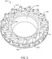
- the swirler 204may be more widely opened or partially closed by moving an actuator ring 206 , as discussed further with respect to Fig. 3 .
- the swirler 204creates a spiraling gas flow 208 of that may enhance mixing, for example, of air with recycled exhaust gas in an oxidant flow, or an oxidant with fuel.
- Fuel 210may be injected through a separate flow path 212 , for example, along the outside of the spiraling gas 208 , which may heat the fuel 210 , enhancing the burn. Injection of the fuel 210 is not limited to a separate flow path 212 , as the fuel 210 may be injected in any number of places. For example, a preheated stream of fuel 214 may be injected down the center of the swirler 204 , mixing with the oxidant 202 in the spiral flow path 208 . The fuel 210 is mixed with the oxidant 202 prior to entering a combustion zone 216 , in which the fuel 210 and oxidant 202 are consumed in a flame 218 .
- Fig. 4is a schematic of a gas turbine system 400 that can be used to individually adjust the oxidant flow to each of a number of combustors 110 .
- the referenced unitsare as generally discussed with respect to Fig. 1 .
- the system 400uses an oxidant flow adjusting device 402 , such as the swirler 204 discussed above, and a mixing section in each combustor 110 .
- An actuator 404can be used to adjust the oxidant flow adjusting device 402 .
- both the oxidant system 116 and the fuel system 114can include numerous devices not shown.
- Such devicescan include flow meters, such as orifice flow meters, mass flow meters, ultrasonic flow meters, venturi flow meters, and the like.
- Other devicescan include valves, such as piston motor valves (PMVs) to open and close lines, and motor valves, such as diaphragm motor valves (DMVs), globe valves, and the like, to regulate flow rates.
- PMVspiston motor valves
- DMVsdiaphragm motor valves
- globe valvesglobe valves
- sensors 406may be separated into multiple rings by the type of sensor 406 , for example, with oxygen analyzers in one ring and temperature sensors in another ring. It will be apparent to one of skill in the art that any number of appropriate arrangements may be used. In addition to, or in place of, sensors 406 in the exhaust expander, sensors may also be disposed in other parts of the gas turbine 102 , as discussed with respect to Figs. 5 and 6 .
- Fig. 5is a schematic of a gas turbine system 500 that includes sensors 502 on the turbine expander 106 .
- the referenced unitsare as described above with respect to Figs. 1 and 4 .
- the sensors 502 on the turbine expander 106send a signal 504 back to the control system 412 , which may be used to make adjustment decisions for each, or all, of the combustors 110 .
- Any number of physical measurementscould be performed on the expander 106 , for example, the sensors 106 could be used to measure temperature, pressure, CO concentration, O 2 concentration, vibration, and the like. Further, multiple sensors 502 could be used to measure combinations of these parameters. Placing sensors 502 on the turbine expander 106 may increase the dependency of each of the sensors 502 on conditions in individual combustors 106 , improving the efficiency of control algorithms. This may be further enhanced, as discussed with respect to Fig. 6 .
- Fig. 6is a schematic of a gas turbine system 600 that includes sensors 602 on the exhaust line 604 out of each combustor 110 .
- the referenced unitsare as described above with respect to Figs. 1 and 4 .
- the sensor 602may measure temperature, pressure, CO concentration, O 2 concentration, or any combinations thereof.
- This arrangement of sensors 602may be combined with sensors 406 placed in the expander exhaust section 408 , or in other locations, to provide data for both specific control of each of the combustors 110 and overall control data for the gas turbine 102 .
- Other techniquesmay also be used in embodiments to gain further control over the combustion process in each of the combustors 110 , as discussed with respect to Fig. 7 .
- Fig. 7is a schematic of a gas turbine system 700 that includes a separate oxidant flow adjusting valve 702 on the oxidant supply line 704 for each combustor 110 .
- the oxidant flow adjusting valve 702can be any variable geometry system designed to control the flow of a gas through a line. The referenced units are as described above with respect to Figs. 1 , 4 , and 6 .
- An actuator 706can be used by the control system 412 to adjust the flow rate of oxidant through the oxidant flow adjusting valve 702 .
- the oxidant flow adjusting valve 702may operate together with the oxidant flow adjusting device 402 to regulate oxidant flow, providing a closer control of the combustion process in the combustor 110.
- an oxidant flow adjusting valve 702may be combined with a sensor 602 ( Fig. 6 ) on the exhaust line 604 from the combustor 110 to provide further control.
- the gas turbines 102may be used to provide power, CO 2 , heat energy, or any combinations thereof for numerous applications.
- the heat from the exhaustmay be recovered as discussed with respect to Fig. 8 .
- Fig. 8is a schematic of a gas turbine system 800 that includes a heat recovery steam generator (HRSG) 802 on the exhaust stream 418 from the expander exhaust section 408 .
- the referenced unitsare as described above with respect to Figs. 1 and 4 .
- the exhaust gas in the exhaust stream 418can include, but is not limited to, fuel, oxygen, carbon monoxide, carbon dioxide, hydrogen, nitrogen, nitrogen oxides, argon, water, steam, or any combination thereof.
- the exhaust stream 418can have a temperature ranging from about 430 °C to about 725 °C and a pressure of about 101 kPa to about 110 kPa.
- the heat generated by the combustioncan be used to boil an inlet water stream 804 to generate a steam stream 806 that may also be superheated.
- the steam stream 806may be used, for example in a Rankine cycle to generate mechanical power from a steam turbine, or to provide steam for utilities, or both.
- the mechanical power from the steam turbinemay be used to generate electricity, operate compressors, and the like.
- the system 800is not limited to a HRSG 802 , as any type of heat recovery unit (HRU) may be used.
- the heatmay be recovered in a heat exchanger to provide hot water or other heated fluids.
- a Rankine cycle based on an organic working fluid (ORC)may be used to recover heat energy by converting it to mechanical energy.
- the cooled exhaust stream 808may then be used for other purposes, such as to provide recycled exhaust for stream 414 , as discussed below.
- Various sensorsmay be added to the system to monitor and control the steam generation process, as discussed with respect to Figs. 9 and 10 .
- Fig. 9is a schematic of a gas turbine system 900 that includes a sensor 902 on the exhaust stream 418 from the expander exhaust section 408 to a heat recovery steam generator (HRSG) 802.
- the referenced unitsare as described above with respect to Figs. 1 , 4 , and 8 .
- a signal 904is provided from the sensor 902 to the control system 412 .
- the sensor 902may be a temperature sensor, a pressure sensor, or any of the sensors discussed previously. Further, the sensor 902 may be a single sensor or a group of sensors, and may be configured to provide information for controlling all of the combustors 110 to adjust the temperature of the exhaust stream 418 from the gas turbine 102 for controlling the HRSG 802 .
- Fig. 10is a schematic of a gas turbine system 1000 that includes a sensor 902 on the cooled exhaust stream 808 from the HRSG 802 .
- the referenced unitsare as described above with respect to Figs. 1 , 4 , and 8 .
- a signal 1004is provided from the sensor 1002 to the control system 412 .
- the sensor 1002may be a temperature sensor, a pressure sensor, or any of the sensors discussed previously. Further, the sensor 1002 may be a single sensor or a group of sensors, and may be configured to provide information for controlling all of the combustors 110 to adjust the temperature of the exhaust stream 418 from the gas turbine 102 .
- the signal 1004may be used by the control system 412 to determine the amount of heat harvested by the HRSG 802 versus the amount of heat wasted in the cooled exhaust stream 808 .
- the sensor 1002may be combined with any or all of the previously discussed sensor arrangements, for example, as shown with respect to Figs. 4 , 5 , 6 , and 8 .
- the heat in the cooled exhaust stream 808 from the HRSG 802may be too high for use in downstream units. Therefore a cooler may be used to remove excess heat, as discussed with respect to Fig. 11 .
- Fig. 11is a schematic of a gas turbine system 1100 that includes a cooler 1102 on the cooled exhaust stream 808 from the HRSG 802 .
- the referenced unitsare as described above with respect to Figs. 1 , 4 , 8 , and 10 .
- the cooler 1102may be a non contact heat exchanger, or any number of other types.
- the cooler 1102may be a counter-current direct contact heat exchanger, in which a water stream 1104 is introduced at the top of a vessel, while the cooled exhaust stream 808 is introduced at the bottom of the vessel. As the water contacts the hot exhaust, it cools the stream by both evaporation and heat exchange.
- a heated water stream 1106is removed from the bottom of the vessel, and may be cooled before being recycled as the water stream 1104 .
- the outlet exhaust stream 1108is both cooled and saturated with water vapor, and may be used as a recycle stream, for example to stream 414 , as discussed with respect to Fig. 12 .
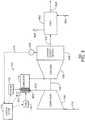
- Fig. 12is a schematic of a gas turbine system 1200 that combines features from a number of the systems discussed above.
- the referenced unitsare as described above with respect to Figs. 1 , 4 , 8 , and 11 .
- the saturated exhaust gas 1202 from the cooler 1102may be recycled to the inlet of the compressor 104 .
- the saturated exhaust gas 1202may be fed to the combustor 110 as stream 416 to assist with cooling the combustor 110 .
- a portion of stream 416may be diverted as an extracted side stream 1204 to a processing system for other use.
- the processing systemmay purify the CO 2 in the side stream 1204, such as by conversion or removal of any CO and O 2 , for injection into a hydrocarbon reservoir to enhance oil recovery. Other uses for the diverted gas may include carbon sequestration.
- the side stream 1204may be directly injected into a underground formation for disposal.
- the gas turbine systems discussed abovemay be used to control the combustion process in each of the combustors 110 individually and as a group.
- one goal of the controlmay be to balance the equivalence ratio of the fuel and oxygen. This may be performed to minimize unburned or partially burned hydrocarbon, represented by the CO concentration in an exhaust stream and to minimize unconsumed oxygen in the exhaust stream.
- the equivalence ratiois discussed further with respect to Fig. 13 .
- the mol% oxygenis equal to F oxygen /(F oxygen + F fuel ), where F oxygen is equal to the molar flow rate of oxygen and F fuel is equal to the molar flow rate of fuel.
- the equivalence ratio ( ⁇ )goes below 1 or above 1 the mole fraction or concentration of oxygen and carbon dioxide in the exhaust gas changes.
- the mole fraction of oxygenrapidly increases from about 1 ppm (i.e., an oxygen mole fraction of about 1.0 x 10 -6 ) at an equivalence ratio ( ⁇ ) of about 1 to about 100 ppm (i.e., an oxygen mole fraction of about 1 x 10 -4 ) at an equivalence ratio of about 0.999.
- the concentration of carbon monoxiderapidly increase from about 1 ppm (i.e., carbon monoxide mole fraction of about 1 x 10 -6 ) at an equivalence ratio ( ⁇ ) of about 0.9995 to greater than about 100 ppm (i.e., a carbon monoxide mole fraction of about 1 x 10 -4 ) at an equivalence ratio ( ⁇ ) of about 1.001.
- the amount of oxidant 116 and/or the amount of fuel 114 to each of the combustors 110can be adjusted to produce an exhaust stream 418 having a desired composition.
- monitoring the oxygen and/or carbon monoxide concentration in the exhaust gas in the expander exhaust section 408, the turbine expander 106, or the exhaust line 604allows the individual adjustment of the amount of oxidant 116 and fuel 114 introduced to each combustor 110 to be controlled such that combustion of the fuel is carried out within a predetermined range of equivalence ratios ( ⁇ ) in that combustor 110.
- a desired or predetermined range for the equivalence ratio ( ⁇ ) in each combustor 110can be calculated or entered to carry out the combustion of the fuel 114 to produce an mixed exhaust stream 418 containing a desired amount of oxygen and/or carbon monoxide.
- the equivalence ratio ( ⁇ ) in each combustor 110can be maintained within a predetermined range of from about 0.85 to about 1.15 to produce an exhaust stream 418 having a combined oxygen and carbon monoxide concentration ranging from a low of about 0.5 mol%, about 0.8 mol%, or about 1 mol%, to a high of about 1.5 mol%, about 1.8 mol%, about 2 mol%, or about 2.2 mol%.
- the equivalence ratio ( ⁇ ) in each of the combustors 110can be maintained within a range of from about 0.96 to about 1.04 to produce an exhaust stream 418 having a combined oxygen and carbon monoxide concentration of less than about 4,000 ppm, less than about 3,000 ppm, less than about 2,000 ppm, less than about 1,000 ppm, less than about 500 ppm, less than about 250 ppm, or less than about 100 ppm.
- the combustors 110do not have to be at the same set-point, or even within the same range.
- different or biased set-pointsmay be used for each of the combustors 110 to account for differences in construction, performance, or operation. This may avoid a situation in which different operational characteristics of different combustors 110 cause the exhaust stream 418 to be contaminated with unacceptable levels of oxygen or carbon monoxide.
- two methods for operating the gas turbine 102are used.
- the entire set of combustors 110is operated as a single entity, for example, during startup and in response to global set-point adjustments, such as speed or power changes.
- the individual combustors 110may be separately biased, for example, to compensate for differences in wear, manufacturing, and the like.
- One method for operating the entire set of combustors 110can include initially, i.e ., on start-up, introducing the fuel 114 and oxygen in the oxidant 116 at an equivalence ratio greater than 1.
- the equivalence ratio ( ⁇ ) at startupmay range from a low of about 1.0001, about 1.0005, about 1.001, about 1.05, or about 1.1, to a high of about 1.1, about 1.2, about 1.3, about 1.4, or about 1.5.
- the equivalence ratio ( ⁇ )can range from about 1.0001 to about 1.1, from about 1.0005 to about 1.01, from about 1.0007 to about 1.005, or from about 1.01 to about 1.1.
- Another method for operating the entire set of combustors 110can include initially, i.e ., on start-up, introducing the fuel 114 and oxygen in the oxidant 116 at an equivalence ratio of less than 1.
- the equivalence ratio ( ⁇ ) at startupmay range from a low of about 0.5, about 0.6, about 0.7, about 0.8, or about 0.9 to a high of about 0.95, about 0.98, about 0.99, about 0.999.
- the equivalence ratio ( ⁇ )can range from about 0.9 to about 0.999 from about 0.95 to about 0.99, from about 0.96 to about 0.99, or from about 0.97 to about 0.99.
- the expanded exhaust gas in the exhaust stream 418should initially have a high concentration of oxygen (e.g., greater than about 1,000 ppm or greater than about 10,000 ppm) and a low concentration of carbon monoxide (e.g., less than about 10 ppm or even less than about 1 ppm).
- a high concentration of oxygene.g., greater than about 1,000 ppm or greater than about 10,000 ppm
- carbon monoxidee.g., less than about 10 ppm or even less than about 1 ppm.
- the concentration of oxygen in the exhaust gasincreases from less than about 1 ppm to greater than about 100 ppm, about 1,000 ppm, about 1 mol%, about 2 mol%, about 3 mol%, or about 4 mol%
- an operator, the control system 412 , or bothcan be alerted that an equivalence ratio ( ⁇ ) of less than 1 has been reached.
- the amount of oxygen via oxidant 116 and fuel 114can be maintained constant or substantially constant to provide a combustion process having an equivalence ratio ( ⁇ ) of slightly less than 1, e.g., about 0.99.
- the amount of oxygen via oxidant 116can be decreased and/or the amount of fuel 114 can be increased and then maintained at a constant or substantially constant amount to provide a combustion process having an equivalence ratio ( ⁇ ) falling within a predetermined range.
- concentration of oxygen in the exhaust stream 418increases from less than about 1 ppm to about 1,000 ppm, about 0.5 mol%, about 2 mol%, or about 4 mol%
- the amount of oxygen introduced via the oxidant 116can be reduced by an amount ranging from a low of about 0.01%, about 0.02%, about 0.03%, or about 0.04 to a high of about 1%, about 2%, about 3%, or about 5% relative to the amount of oxygen introduced via the oxidant 116 at the time the increase in oxygen in the exhaust gas is initially detected.
- the amount of oxygen introduced via the oxidant 116can be reduced by about 0.01% to about 2%, about 0.03% to about 1%, or about 0.05% to about 0.5% relative to the amount of oxygen introduced via the oxidant 116 at the time the increase in oxygen in the exhaust gas is detected.
- the amount of fuel 114can be increased by an amount ranging from a low of about 0.01%, about 0.02%, about 0.03%, or about 0.04 to a high of about 1%, about 2%, about 3%, or about 5% relative to the amount of fuel 114 introduced at the time the increase in oxygen in the exhaust gas is initially detected.
- the equivalence ratio ( ⁇ )can be monitored via the sensors 406 , 502 , or 602 on a continuous basis, at periodic time intervals, at random or non-periodic time intervals, when one or more changes to the gas turbine system 102 occur that could alter or change the equivalence ratio ( ⁇ ) of the exhaust stream 418 , or any combination thereof.
- changes that could occur to the gas turbine system 102 that could alter or change the equivalence ratio ( ⁇ )can include a change in the composition of the fuel, a change in the composition of the oxidant, or a combination thereof.
- the concentration of oxygen and/or carbon monoxidefor example, can be monitored, and adjustments can be made to the amount of oxidant 116 and/or fuel 114 to control the amounts of oxygen and/or carbon monoxide in the exhaust stream 418 .
- reducing the equivalence ratio ( ⁇ )can be carried out in incremental steps, non-incremental steps, a continuous manner, or any combination thereof.
- the amount of oxidant 116 and/or the fuel 114can be adjusted such that the equivalence ratio ( ⁇ ) changes by a fixed or substantially fixed amount per adjustment to the oxidant 116 and/or fuel 114 , e.g ., by about 0.001, by about 0.01, or by about 0.05.
- the amount of oxidant 116 and/or fuel 114can be continuously altered such that the equivalence ratio continuously changes.
- the amount of oxidant 116 and/or fuel 114is altered and combustion is carried out for a period of time sufficient to produce an exhaust gas of substantially consistent composition, at which time the amount of oxidant 116 and/or fuel 114 can be adjusted to change the equivalence ratio ( ⁇ ) in an amount ranging form a low of about 0.00001, about 0.0001, or about 0.0005 to a high of about 0.001, about 0.01, or about 0.05.
- the exhaust stream 418achieves a substantially consistent concentration of oxygen the oxidant 116 and/or fuel 114 can again be adjusted such that the equivalence ratio ( ⁇ ) changes.
- the amount of oxygen and/or carbon monoxide in the exhaust stream 418can be monitored and the amount of oxidant 116 and/or fuel 114 can be repeatedly adjusted until the exhaust stream 418 has a combined concentration of oxygen and carbon monoxide, for example, of less than about 2 mol% or less than about 1.5 mol%, or less than about 1 mol%.
- the combustors 110can be operated on a continuous basis such that the exhaust stream 418 has a combined oxygen and carbon monoxide concentration of less than 2 mol%, less than 1 mol%, less than 0.5 mol%, or less than about 0.1 mol%.
- the time during which combustion is carried out within the combustors 110the exhaust stream 418 can have a combined oxygen and carbon monoxide concentration of less than 2 mol% or less than about 1 mol% for about 50%, 55%, 60%, 65%, 70%, 75%, 80%, 85%, 90%, or about 95% of the time during which the gas turbine 102 is operated.
- the exhaust stream 418can have a combined oxygen and carbon monoxide concentration of less than about 2 mol%, less than about 1 mol%, less than about 0.5 mol%, or less than about 0.1 mol%.
- the biasing needed for individual combustors 110may be determined in the second method. For example, referring to Fig. 4 , based on data signals 410 from the sensors 406 in the expander exhaust section 408 , the oxidant flow adjusting device 402 for each individual combustor 110 can be adjusted by the control system 412 to maintain the measured value of the sensors 406 at or near to a desired set-point. Several calculated values may be determined from the measured values of each sensor 406 . These may include, for example, an average value that can be used to make similar adjustments to all of the oxidant flow adjusting devices 402 in the n combustors 110 , as discussed with respect to the first method.
- various difference valuesmay be used to make biasing adjustments to the oxidant flow adjusting devices 402 on one or more of the combustors 110 to minimize differences between the measured values of the sensors 406 .
- the control system 412may also adjust the oxidant system 116 directly, such by adjusting compressor inlet guide vanes (IGV) or a speed control to change the oxidant flow rates, for example, to all of the combustors 110 at once. Further, the control system 412 can make similar adjustments to the fuel 114 to all combustors 110 , depending, for example, on the speed selected for the gas turbine 102 .
- the fuel supply to each of the combustors 110may be individually biased to control the equivalence ratio of the burn. This is discussed further with respect to Fig. 15 .
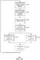
- Fig. 14is a block diagram of a method 1400 for biasing individual combustors 110 based on readings from an array of sensors 406 . It can be assumed that the gas turbine 102 has been started before this method 1400 begins, and that all of the combustors 110 are using essentially the same mixture or a previous operation point.
- the method 1400begins at block 1402 at which readings are obtained from the sensors 406 or 502 .
- sums and differencesare determined between the measurements obtained from the individual sensors 406 or 502 .
- the sums and differencesmay be combined to assist in identifying the combustors 110 that are contributing to a high oxygen or high carbon monoxide condition in the exhaust.
- Adjustments to the fuel 114 and oxidant 116 for those combustors 110are calculated at block 1408 , for example, using the same considerations for the particular combustors 110 involved as used for adjusting all of the combustors 110 in the first method.
- the new set-point for the oxidant 116is entered and oxidant is provided to the combustors 110 .
- a new set-pointis entered for the fuel 114 , and fuel 114 is provided to the combustors 110 .
- the combustion processconsumed the fuel 114 and oxidant 116 provided. Process flow then returns to block 1402 , wherein the method repeats.
- each combustor 110has a separate sensor 602 located on an exhaust line 604 from the combustor 110 .
- the effects of changes to individual combustors 110may be made, and a precise adjustment to the oxidant 116 and fuel 114 may be made for any combustor 110 providing too high of an oxygen or carbon monoxide exhaust, for example, using the techniques discussed with respect to the first method.
- These adjustmentsmay be made in addition to any uniform adjustments made in the entire set of combustors 110 , for example, in response to a set-point change in the operating speed of the gas turbine 102 .
- the control system 1500may have a processor 1502, which may be a single core processor, a multiple core processor, or a series of individual processors located in systems through the plant control system 1500.
- the processor 1502can communicate with other systems, including distributed processors, in the plant control system 1500 over a bus 1504.
- the bus 1504may be an Ethernet bus, a FIELDBUS, or any number of other buses, including a proprietary bus from a control system vendor.
- a storage system 1506may be coupled to the bus 1504, and may include any combination of non-transitory computer readable media, such as hard drives, optical drives, random access memory (RAM) drives, and memory, including RAM and read only memory (ROM).
- the storage system 1506may store code used to provide operating systems 1508 for the plant, as well as code to implement turbine control systems 1510, for example, bases on the first or second methods discussed above.
- a human-machine interface 1512may provide operator access to the plant control system 1500, for example, through displays 1514, keyboards 1516, and pointing devices 1518 located at one or more control stations.
- a network interface 1520may provide access to a network 1522, such as a local area network or wide area network for a corporation.
- a plant interface 1524may provide measurement and control systems for a first gas turbine system.
- the plant interface 1524may read a number of sensors 1526, such as the sensors 406, 502, 602, 902, and 1002 described with respect to Figs. 4 , 5 , 6 , 9 , and 10 .
- the plant interface 1524may also make adjustments to a number of controls, including, for example, fuel flow controls 1528 used adjust the fuel 114 to the combustors 110 on the gas turbine 102.
- Other controlsinclude the oxidant flow controls 1530, used, for example, to adjust the actuator 404 on an oxidant flow adjusting device 402, the actuator 706 on a oxidant flow adjusting valve 702, or both, for each of the combustors 110 on the gas turbine 102.
- the plant interface 1524may also control other plant systems 1532, such as generators used to produce power from the mechanical energy provided by the gas turbine 102.
- the additional plant systems 1532may also include the compressor systems used to provide oxidant 116 to the
- the plant control system 1500is not limited to a single plant interface 1524 . If more turbines are added, additional plant interfaces 1534 may be added to control those turbines. Further, the distribution of functionality is not limited to that shown in Fig. 15 . Different arrangements could be used, for example, one plant interface system could operate several turbines, while another plant interface system could operate compressor systems, and yet another plant interface could operate generation systems.
Landscapes
- Engineering & Computer Science (AREA)
- Chemical & Material Sciences (AREA)
- Combustion & Propulsion (AREA)
- Mechanical Engineering (AREA)
- General Engineering & Computer Science (AREA)
- Physics & Mathematics (AREA)
- Fluid Mechanics (AREA)
- Life Sciences & Earth Sciences (AREA)
- Sustainable Development (AREA)
- Dispersion Chemistry (AREA)
- Engine Equipment That Uses Special Cycles (AREA)
- Control Of Turbines (AREA)
Description
- The present disclosure relates generally to low-emission power generation systems. More particularly, the present disclosure relates to systems and methods for optimizing substantially stoichiometric combustion in gas turbine systems.
- This section is intended to introduce various aspects of the art, which may be associated with exemplary embodiments of the present techniques. This discussion is believed to assist in providing a framework to facilitate a better understanding of particular aspects of the present techniques. Accordingly, it should be understood that this section should be read in this light, and not necessarily as admissions of prior art.
- The combustion of fuel within a combustor,e.g., integrated with a gas turbine, can be controlled by monitoring the temperature of the exhaust gas. At full load, typical gas turbines adjust the amount of fuel introduced to a number of combustors in order to reach a desired combustion gas or exhaust gas temperature. Conventional combustion turbines control the oxidant introduced to the combustors using inlet guide vanes. At partial load, the amount of oxidant introduced to the combustor is reduced and the amount of fuel introduced is again controlled to reach the desired exhaust gas temperature. At partial load, the efficiency of gas turbines drops because the ability to reduce the amount of oxidant is limited by the inlet guide vanes, which are only capable of slightly reducing the flow of oxidant. Further, the oxidant remains at a constant lower flow rate when the inlet guide vanes are in their flow restricting position. The efficiency of the gas turbine then drops when it is at lower power production because to make that amount of power with that mass flow a lower expander inlet temperature is required. Moreover, existing oxidant inlet control devices may not allow fine flow rate control and may introduce large pressure drops with any restriction on the oxidant flow. With either of these approaches to oxidant control, there are potential problems with lean blow out at partial load or reduced pressure operations.
- Controlling the amount of oxidant introduced to the combustor can be desirable when an objective is to capture carbon dioxide (CO2) from the exhaust gas. Current carbon dioxide capture technology is expensive due to several reasons. One reason is the low pressure and low concentration of carbon dioxide in the exhaust gas. The carbon dioxide concentration, however, can be significantly increased from about 4% to greater than 10% by operating the combustion process under substantially stoichiometric conditions. Further, a portion of the exhaust gas may be recycled to the combustor as a diluent in order to control the temperature of the exhaust gas. Also, any unused oxygen in the exhaust gas may be a contaminate in the captured carbon dioxide, restricting the type of solvents that can be utilized for the capture of carbon dioxide.
- In many systems, an oxidant flow rate may be reduced by altering the operation of a separate oxidant system. For example, an independent oxidant compressor may be throttled back to a slower operating speed thereby providing a decreased oxidant flow rate. However, the reduction in compressor operating speed generally decreases the efficiency of the compressor. Additionally, throttling the compressor may reduce the pressure of the oxidant entering the combustor. In contrast, if the oxidant is provided by the compressor section of the gas turbine, reducing the speed is not a variable that is controllable during power generation. Gas turbines that are used to produce 60 cycle power are generally run at 3600 rpm. Similarly, to produce 50 cycle power the gas turbine is often run at 3000 rpm. In conventional gas turbine combustor operations the flow of oxidant into the combustor may not warrant significant control because the excess oxidant is used as coolant in the combustion chamber to control the combustion conditions and the temperature of the exhaust gas. A number of studies have been performed to determine techniques for controlling combustion processes in gas turbines.
- For example,
U.S. Patent No. 6,332,313 to Willis, et al. , discloses a combustion chamber with separate, valved air mixing passages for separate combustion zones. A combustion chamber assembly includes a primary, a secondary and a tertiary fuel and air mixing ducts to supply fuel and air to each of primary, secondary and tertiary combustion zones, respectively. Each of the primary, secondary and tertiary fuel and air mixing ducts includes a pair of axial flow swirlers, which are arranged coaxially to swirl the air in opposite directions and fuel injectors to supply fuel coaxially to the respective axial flow swirlers. Valves are provided to control the supply of air to the primary and the secondary fuel and air mixing ducts respectively. A duct is arranged to supply cooling air and dilution air to the combustion chamber. The amount of air supplied to the primary, secondary and tertiary fuel and air mixing ducts and the duct is measured. - International Patent Application Publication No.
WO/2010/044958 by Mittricker, et al. , discloses methods and systems for controlling the products of combustion, for example, in a gas turbine system. One embodiment includes a combustion control system having an oxygenation stream substantially comprising oxygen and CO2 and having an oxygen to CO2 ratio, then mixing the oxygenation stream with a combustion fuel stream and combusting in a combustor to generate a combustion products stream having a temperature and a composition detected by a temperature sensor and an oxygen analyzer, respectively. The data from the sensors are used to control the flow and composition of the oxygenation and combustion fuel streams. The system may also include a gas turbine with an expander and having a load and a load controller in a feedback arrangement. - International Patent Application Publication No.
WO/2009/120779 by Mittricker, et al. , discloses systems and methods for low emission power generation and hydrocarbon recovery. One system includes integrated pressure maintenance and miscible flood systems with low emission power generation. Another system provides for low emission power generation, carbon sequestration, enhanced oil recovery (EOR), or carbon dioxide sales using a hot gas expander and external combustor. Another system provides for low emission power generation using a gas power turbine to compress air in the inlet compressor and generate power using hot carbon dioxide laden gas in the expander. U.S. Patent No. 4,858,428 to Paul discloses an advanced integrated propulsion system with total optimized cycle for gas turbine. Paul discloses a gas turbine system with integrated high and low pressure circuits having a power transmission for extracting work from one of the circuits, the volume of air and fuel to the respective circuits being varied according to the power demand monitored by a microprocessor. The turbine system has a low pressure compressor and a staged high pressure compressor with a combustion chamber and high pressure turbine associated with the high pressure compressor. A combustion chamber and a low pressure turbine are associated with the low pressure compressor, the low pressure turbine being staged with the high pressure turbine to additionally receive gases expended from the high pressure turbine and a microprocessor to regulate air and gas flows between the compressor and turbine components in the turbine system.U.S. Patent No. 4,271,664 to Earnest discloses a turbine engine with exhaust gas recirculation. The engine has a main power turbine operating on an open-loop Brayton cycle. The air supply to the main power turbine is furnished by a compressor independently driven by the turbine of a closed-loop Rankine cycle which derives heat energy from the exhaust of the Brayton turbine. A portion of the exhaust gas is recirculated into the compressor inlet during part-load operation.U.S. Patent Application Publication No. 2009/0064653 by Hagen, et al. , discloses partial load combustion cycles. The part load method controls delivery of diluent fluid, fuel fluid, and oxidant fluid in thermodynamic cycles using diluent to increase the turbine inlet temperature and thermal efficiency in part load operation above that obtained by relevant art part load operation of Brayton cycles, fogged Brayton cycles, or cycles operating with some steam delivery, or with maximum steam delivery.EP0529900A andUS2004/219079A disclose gas turbine systems with sensor.- While some past efforts to control the oxidant flow rate have implemented oxidant inlet control devices, such systems disclosed a control of all of the combustors together, failing to account for differences between combustors. Further, the systems were limited in their ability to finely tune the oxidant flow rate.
- The invention is defined by the subject-matter of
independent claims - The oxidant may include oxygen and a diluent. A diluent supply is provided to each of the plurality of combustors. An oxidant compressor may be used to provide compressed oxidant to the combustors.
- The oxidant-flow adjustment device may include a flow control valve. The oxidant-flow adjustment device may include an adjustable swirler sub assembly. The adjustable swirler sub assembly may include an annular control assembly positioned around a flow sleeve to controllably regulate oxidant flow rates into the flow sleeve. The annular control assembly includes a plurality of articulating vanes operatively associated with a mounting ring and an actuator vane. The plurality of vanes is adapted to be controllably adjusted between an open position and a closed position and positions therebetween by moving the actuator vane relative to the mounting vane.
- The gas turbine includes a plurality of exhaust sensors that are adapted to work with the control system to regulate oxidant flow rates to each of the plurality of combustors so as to minimize differences between measured parameters at different exhaust sensors. The oxidant-flow adjustment device on at least one of the plurality of combustors is adapted to increase mixing of the oxidant, the fuel, a diluent, or any combinations thereof.
- A combustor may include a diluent inlet and an oxidant inlet, in which an oxidant-flow adjustment device is disposed in the oxidant inlet. The oxidant-flow adjustment device may be configured to mix the oxidant and the diluent before the fuel is introduced.
- A turbine expander may be adapted to receive the exhaust gas and to generate power. A heat recovery steam generator may be adapted to receive the exhaust gas from the turbine expander and to generate power. A diluent compressor and an exhaust gas recirculation loop may be adapted to receive the exhaust gas from the expander, in which the exhaust gas recirculation loop includes a heat recovery steam generator adapted to generate power, and a cooled exhaust line can be adapted to provide cooled exhaust gas to the diluent compressor, and in which the diluent compressor is adapted to provide compressed diluent to the combustor.
- An exhaust gas extraction system may be disposed between the diluent compressor and the combustor, wherein the exhaust gas extraction system may extract diluent at elevated pressures.
- Another exemplary embodiment according to
claim 13 provides a method of controlling a gas turbine. The method includes providing a fuel to a plurality of combustors on a gas turbine, and providing an oxidant to the plurality of combustors, wherein an oxidant flow rate is independently adjusted for each of the plurality of combustors. The fuel and the oxidant are combusted in the plurality of combustors to produce an exhaust gas. A parameter of the exhaust gas is measured and the oxidant flow rate into each of the plurality of combustors is adjusted to control the parameter to within a target set-point range. - The method may include compressing the oxidant before the oxidant is provided to each of the plurality of combustors. A portion of the exhaust gas may be returned to the plurality of combustors as a diluent. The diluent may be compressed with a compressor before the diluent enters the combustor. The compressor may be operatively coupled to an expander adapted to receive the exhaust gas and to generate power therefrom.
- At least a portion of the exhaust gas may be extracted from a coupling disposed between the compressor and each of the plurality of combustors, wherein the amount of exhaust gas extracted is based, at least in part, on the parameter.
- Another exemplary embodiment according to claim 18 provides a non-transitory computer readable medium comprising code which when executed by a processor installed on a gas turbine system according to
claim 1, directs the processor to provide a fuel to a plurality of combustors on a gas turbine and provide an oxidant to the plurality of combustors, wherein an oxidant flow rate is independently adjusted for each of the plurality of combustors. The code also directs the processor to monitor a parameter of an exhaust gas produced in a flame in the combustors and adjust the oxidant flow rate into each of the plurality of combustors to control the parameter to within a target set-point range. The parameter may be a concentration of oxygen in the exhaust gas. The parameter may be a concentration of carbon monoxide in the exhaust gas. - The non-transitory computer readable medium may include a data structure representing a swirl chart. The code may be configured to direct the processor to compare measurements associated with a plurality of sensors to the data structure to determine which of the plurality of combustors to adjust. The code may be configured to direct the processor to obtain measurements from a plurality of exhaust sensors. The code may be configured to direct the processor to regulate oxidant flow rates to each of the plurality of combustors so as to minimize differences between measured parameters at different exhaust sensors.
- The advantages of the present techniques are better understood by referring to the following detailed description and the attached drawings, in which:
Fig. 1 is a schematic diagram of a gas turbine system that includes a gas turbine;Fig. 2 is a diagram illustrating a portion of a combustor, such as the combustors discussed with respect toFig. 1 ;Fig. 3 is a drawing of a swirler, as discussed with respect toFig. 2 ;Fig. 4 is a schematic of a gas turbine system that can be used to individually adjust the oxidant flow to each of a number of combustors;Fig. 5 is a schematic of a gas turbine system that includes sensors on the turbine expander;Fig. 6 is a schematic of a gas turbine system that includes sensors on the exhaust line out of each combustor;Fig. 7 is a schematic of a gas turbine system that includes a separate oxidant flow adjusting valve on the oxidant supply line for each combustor;Fig. 8 is a schematic of a gas turbine system that includes a heat recovery steam generator (HRSG) on the exhaust stream from the expander exhaust section;Fig. 9 is a schematic of a gas turbine system that includes a sensor on the exhaust stream from the expander exhaust section to a heat recovery steam generator (HRSG);Fig. 10 is a schematic of a gas turbine system that includes a sensor on the cooled exhaust stream from the HRSG;Fig. 11 is a schematic of a gas turbine system that includes a cooler on the cooled exhaust stream from the HRSG;Fig. 12 is a schematic of a gas turbine system that combines features from a number of the systems discussed above;Figs. 13A and13B are graphical depictions of a simulation showing the relationship between the concentration of oxygen and carbon monoxide as the equivalence ratio (φ) changes from 0.75 to 1.25 and from 0.999 to 1.001, respectively;Fig. 14 is a block diagram of a method for biasing individual combustors based on readings from an array of sensors; andFig. 15 is a block diagram of a plant control system that may be used to individually control the oxidant and fuel to a number of combustors in a gas turbine.- In the following detailed description section, specific embodiments of the present techniques are described. However, to the extent that the following description is specific to a particular embodiment or a particular use of the present techniques, this is intended to be for exemplary purposes only and simply provides a description of the exemplary embodiments. Accordingly, the techniques are not limited to the specific embodiments described below, but are defined by the scope of the appended claims.
- At the outset, for ease of reference, certain terms used in this application and their meanings as used in this context are set forth. To the extent a term used herein is not defined below, it should be given the broadest definition persons in the pertinent art have given that term as reflected in at least one printed publication or issued patent.
- An "adsorbent" may be used to extract or sequester CO2 from an exhaust gas flow. The absorbent may be used in a series of parallel beds, which can be switched when an absorbent in a bed has reached capacity. The bed that is removed from the flow can then be treated, such as heated, to desorb the CO2.
- Suitable adsorbents for CO2 sequestration in the present applications have reasonably large working capacity over the relevant temperature range and composition range, good selectivity for CO2 over other undesired constituents (such as N2 and O2), good kinetics, high durability, good compatibility, and reasonably low cost. Several solid phase adsorbents are potential candidates for CO2 capture. For example, molecular sieves are materials whose atoms are arranged in a lattice or framework in such a way that a large number of interconnected uniformly sized pores exist. The pores generally only admit molecules of a size about equal to or smaller than that of the pores. Molecular sieves, thus, can be used to adsorb and separate or screen molecules based on their size with respect to the pores. One class of molecular sieves is zeolites. Zeolites are hydrated silicates of aluminum and frequently contain cations, which are exchangeable. Zeolites can be naturally occurring or artificial. Naturally occurring types include chabazite, clinoptilolite, erionite, heulandite, and mordenite, to name but a few. Artificial zeolites including, for example, types A, D, L, R, S, T, X, Y, ZSM, mordenite, or clinoptilolite, may also be used. Liquid phase, or solvent adsorption systems, such as those based on chemisorption, may also be used. These may include systems based on carbonates, or amines, among others.
- "Physical absorption" means absorbing a product, such as carbon dioxide, from a gaseous feed stream by passing the feed stream into a liquid which preferentially adsorbs the product from the feed stream at a relatively high pressure, for example, about 2.07 to 13.8 MPa. The feed stream that is depleted of the absorbed product is removed from the liquid. The product can then be recovered from the liquid such as by lowering the pressure over the liquid or by stripping the product out of the liquid. Unlike other solvent based processes, such as those based on amines or carbonates, the absorption of the carbon dioxide into the liquid does not involve a chemical reaction of the carbon dioxide. An example of a physical adsorption process is the SELEXOL™ process available from the UOP LLC subsidiary of the HONEYWELL Corporation.
- A "carbon sequestration facility" is a facility in which carbon dioxide can be controlled and sequestered in a repository such as, for example, by introduction into a mature or depleted oil and gas reservoir, an unmineable coal seam, a deep saline formation, a basalt formation, a shale formation, or an excavated tunnel or cavern. Further, sequestration can be combined with other uses for the sequestered gas, such as increasing hydrocarbon production in tertiary oil recovery from an active reservoir.
- A "combined cycle power plant" uses both steam and gas turbines to generate power. The gas turbine operates in an open Brayton cycle, and the steam turbine operates in a Rankine cycle powered by the heat from the gas turbine. These combined cycle gas/steam power plants generally have a higher energy conversion efficiency than gas or steam only plants. A combined cycle plant's efficiencies can be as high as 50 % to 60 %. The higher combined cycle efficiencies result from synergistic utilization of a combination of the gas turbine with the steam turbine. Typically, combined cycle power plants utilize heat from the gas turbine exhaust to boil water to generate steam. The boilers in typical combined cycle plants can be referred to as heat recovery steam generator (HRSG). The steam generated is utilized to power a steam turbine in the combined cycle plant. The gas turbine and the steam turbine can be utilized to separately power independent generators, or in the alternative, the steam turbine can be combined with the gas turbine to jointly drive a single generator via a common drive shaft.
- A diluent is a gas used to lower the concentration of oxidant fed to a gas turbine to combust a fuel. The diluent may be an excess of nitrogen, CO2, combustion exhaust, or any number of other gases. In embodiments, a diluent may also provide cooling to a combustor.
- As used herein, a "compressor" includes any type of equipment designed to increase the pressure of a working fluid, and includes any one type or combination of similar or different types of compression equipment. A compressor may also include auxiliary equipment associated with the compressor, such as motors, and drive systems, among others. The compressor may utilize one or more compression stages, for example, in series. Illustrative compressors may include, but are not limited to, positive displacement types, such as reciprocating and rotary compressors for example, and dynamic types, such as centrifugal and axial flow compressors, for example. For example, a compressor may be a first stage in a gas turbine engine, as discussed in further detail below.
- A "control system" typically comprises one or more physical system components employing logic circuits that cooperate to achieve a set of common process results. In an operation of a gas turbine engine, the objectives can be to achieve a particular exhaust composition and temperature. The control system can be designed to reliably control the physical system components in the presence of external disturbances, variations among physical components due to manufacturing tolerances, and changes in inputted set-point values for controlled output values. Control systems usually have at least one measuring device, which provides a reading of a process variable, which can be fed to a controller, which then can provide a control signal to an actuator, which then drives a final control element acting on, for example, an oxidant stream. The control system can be designed to remain stable and avoid oscillations within a range of specific operating conditions. A well-designed control system can significantly reduce the need for human intervention, even during upset conditions in an operating process.
- An "equivalence ratio" refers to the mass ratio of fuel to oxygen entering a combustor divided by the mass ratio of fuel to oxygen when the ratio is stoichiometric. A perfect combustion of fuel and oxygen to form CO2 and water would have an equivalence ratio of 1. A too lean mixture, e.g., having more oxygen than fuel, would provide an equivalence ratio less than 1, while a too rich mixture, e.g., having more fuel than oxygen, would provide an equivalence ratio greater than 1.
- A "fuel" includes any number of hydrocarbons that may be combusted with an oxidant to power a gas turbine. Such hydrocarbons may include natural gas, treated natural gas, kerosene, gasoline, or any number of other natural or synthetic hydrocarbons.
- A "gas turbine" engine operates on the Brayton cycle. If the exhaust gas is vented, this is termed an open Brayton cycle, while recycling of the exhaust gas gives a closed Brayton cycle. As used herein, a gas turbine typically includes a compressor section, a number of combustors, and a turbine expander section. The compressor may be used to compress an oxidant, which is mixed with a fuel and channeled to the combustors. The mixture of fuel and oxidant is then ignited to generate hot combustion gases. The combustion gases are channeled to the turbine expander section which extracts energy from the combustion gases for powering the compressor, as well as producing useful work to power a load. In embodiments discussed herein, the oxidant may be provided to the combustors by an external compressor, which may or may not be mechanically linked to the shaft of the gas turbine engine. Further, in embodiments, the compressor section may be used to compress a diluent, such as recycled exhaust gases, which may be fed to the combustors as a coolant.
- A "heat recovery steam generator" or HRSG is a heat exchanger or boiler that recovers heat from a hot gas stream. It produces steam that can be used in a process or used to drive a steam turbine. A common application for an HRSG is in a combined-cycle power plant, where hot exhaust from a gas turbine is fed to the HRSG to generate steam which in turn drives a steam turbine. This combination produces electricity more efficiently than either the gas turbine or steam turbine alone.
- A "hydrocarbon" is an organic compound that primarily includes the elements hydrogen and carbon, although nitrogen, sulfur, oxygen, metals, or any number of other elements may be present in small amounts. As used herein, hydrocarbons generally refer to components found in raw natural gas, such as CH4, C2H2, C2H4, C2H6, C3 isomers, C4 isomers, benzene, and the like.
- An "oxidant" is a gas mixture that can be flowed into the combustors of a gas turbine engine to combust a fuel. As used herein, the oxidant may be oxygen mixed with any number of other gases as diluents, including CO2, N2, air, combustion exhaust, and the like.
- A "sensor" refers to any device that can detect, determine, monitor, record, or otherwise sense the absolute value of or a change in a physical quantity. A sensor as described herein can be used to measure physical quantities including, temperature, pressure, O2 concentration, CO concentration, CO2 concentration, flow rate, acoustic data, vibration data, chemical concentration, valve positions, or any other physical data.
- "Pressure" is the force exerted per unit area by the gas on the walls of the volume. Pressure can be shown as pounds per square inch (psi). "Atmospheric pressure" refers to the local pressure of the air. "Absolute pressure" (psia) refers to the sum of the atmospheric pressure (14.7 psia or 1.014 bar at standard conditions) plus the gage pressure (psig). "Gauge pressure" (psig) refers to the pressure measured by a gauge, which indicates only the pressure exceeding the local atmospheric pressure (i.e., a gauge pressure of 0 psig corresponds to an absolute pressure of 14.7 psia or 1.014 bar). The term "vapor pressure" has the usual thermodynamic meaning. For a pure component in an enclosed system at a given pressure, the component vapor pressure is essentially equal to the total pressure in the system.
- "Substantial" when used in reference to a quantity or amount of a material, or a specific characteristic thereof, refers to an amount that is sufficient to provide an effect that the material or characteristic was intended to provide. The exact degree of deviation allowable may in some cases depend on the specific context.
- Embodiments of the present invention provide a system and a method for individually controlling a number of combustors on a gas turbine engine. The control may be based, at least in part, on measurements from sensors, for example, located in a ring on an exhaust expander. The sensors may include oxygen sensors, carbon monoxide sensors, and temperature sensors, among others. Further, combinations of different types of sensors may be used to provide further information.
- The sensors may not have a one-to-one relationship to particular combustors, but may be influenced by a particular combustor. The response of various sensors may be related back to a particular combustor, for example, using sum and difference algorithms that may be based on swirl charts. Swirl charts relate patterns of exhaust flow in an expander to combustors that may have contributed to the exhaust flow at that point.
- The use of individually controlled combustors may increase the burn efficiency of a gas turbine engine, e.g., making the burn closer to a one-to-one equivalence ratio. Such improvements in efficiency may lower O2 and unburned hydrocarbons in the exhaust and make capturing CO2 from the exhaust gas more efficient. This may improve the capture of the CO2 from the turbine for use in enhanced oil recovery, as well as in sequestration.
Fig. 1 is a schematic diagram of agas turbine system 100 that includes agas turbine 102. Thegas turbine 102 may have acompressor 104 and aturbine expander 106 on asingle shaft 108. Thegas turbine 102 is not limited to a single shaft arrangement, as multiple shafts could be used, generally with mechanical linkages or transmissions between shafts. In embodiments, thegas turbine 102 also has a number ofcombustors 110 that feed hot exhaust gas to the expander, for example, throughlines 112. For example, agas turbine 102 may have 2, 4, 6, 14, 18, or evenmore combustors 110, depending on the size of thegas turbine 102.- The
combustors 110 are used to burn a fuel provided by afuel source 114. An oxidant may be provided to each of thecombustors 110 from various sources. For example, in embodiments, anexternal oxidant source 116, such as an external compressor, may provide the oxidant to thecombustors 110. In embodiments, an oxidant or recycledexhaust gases 118, or a mixture thereof, may be compressed in thecompressor 104 and then provided to thecombustors 110. In other embodiments, such as when anexternal oxidant source 116 is provided, thecompressor 104 may be used to compress only the recycled exhaust gas, which may be fed to thecombustors 110 for cooling and dilution of the oxidant. - The exhaust gas from the
combustors 110 expands in theturbine expander 106, creating mechanical energy. The mechanical energy may power thecompressor 104 through theshaft 108. Further, a portion of the mechanical energy may be harvested from the gas turbine as amechanical power output 120, for example, to generate electricity or to power oxidant compressors. The expandedexhaust gas 122 may be vented, used for heat recovery, recycled to thecompressor 104, or used in any combinations thereof. - In embodiments, the oxidant can be individually metered to each of the
combustors 110 to control an equivalence ratio in thatcombustor 110. It will be apparent to one of skill in the art that a stoichiometric burn,e.g., at an equivalence ratio of 1, will be hotter than a non-stoichiometric burn. Therefore, either excess oxidant or an added non-combustible gas, such as a recycle exhaust gas, can be added to cool the engine, preventing damage to thecombustors 110 or theturbine expander 106 from the extreme heat. The use ofrecycled exhaust gas 122 provides a further advantage in that the exhaust is deficient in oxygen, making it a better material for enhanced oil recovery. Further, individually adjusting the oxidant to each combustor110, for example, as discussed with respect toFigs. 2 and3 , may compensate for differences between thecombustors 110, improving the overall efficiency of thegas turbine 102. Control of the mixture parameters to each of thecombustors 110 is discussed further with respect toFigs. 13A ,13B , and14 . Fig. 2 is a diagram200 illustrating a portion of a combustor, such as thecombustors 110 discussed with respect toFig. 1 . It will be clear that this is merely one example of acombustor 110, as many other options are available. As shown in the diagram200, anoxidant 202 may be fed into anadjustable oxidant swirler 204. Theswirler 204 may be more widely opened or partially closed by moving anactuator ring 206, as discussed further with respect toFig. 3 . Theswirler 204 creates a spiralinggas flow 208 of that may enhance mixing, for example, of air with recycled exhaust gas in an oxidant flow, or an oxidant with fuel.Fuel 210 may be injected through aseparate flow path 212, for example, along the outside of the spiralinggas 208, which may heat thefuel 210, enhancing the burn. Injection of thefuel 210 is not limited to aseparate flow path 212, as thefuel 210 may be injected in any number of places. For example, a preheated stream offuel 214 may be injected down the center of theswirler 204, mixing with theoxidant 202 in thespiral flow path 208. Thefuel 210 is mixed with theoxidant 202 prior to entering acombustion zone 216, in which thefuel 210 andoxidant 202 are consumed in aflame 218. The adiabatic flame temperature of a stoichiometric combustion of methane in air is about 1960 °C and a stoichiometric combustion of methane in oxygen is about 2800 °C). Accordingly, cooling may be needed to decrease the chance of damage to the equipment. Thus, in embodiments, a diluent may be added tooxidant 202 for cooling purposes as it is injected into theadjustable oxidant swirler 204. In embodiments, the diluent may be recycled exhaust gas, nitrogen, or other gases that do not participate in the combustion process.Fig. 3 is a drawing of aswirler 204, as discussed with respect toFig. 2 . Theswirler 204 has a number ofvanes 302 that direct anoxidant flow 304 through athroat opening 306 between each of thevanes 302. Anactuator ring 206 can be used to adjust the size of thethroat openings 306. For example, when the actuator ring changes angle, thevanes 302 can open or close, adjusting theoxidant flow 304 into thethroat 308. Anadjustable swirler 204 may be included in each combustor110 (Fig. 1 ) to modify the oxidant amount fed to thecombustor 110. A system that may use aswirler 204 to adjust the amount of oxidant to each combustor110 is shown inFig. 4 .Fig. 4 is a schematic of agas turbine system 400 that can be used to individually adjust the oxidant flow to each of a number ofcombustors 110. The referenced units are as generally discussed with respect toFig. 1 . Thesystem 400 uses an oxidantflow adjusting device 402, such as theswirler 204 discussed above, and a mixing section in eachcombustor 110. Anactuator 404 can be used to adjust the oxidantflow adjusting device 402.- A number of
sensors 406 can be placed in anexpander exhaust section 408 of thegas turbine 102, for example, 5, 10, 15, 20, 25, 30 or more,sensors 406 may be placed in a ring around theexpander exhaust section 408. The number ofsensors 406 may be determined by the size of thegas turbine 102. Thesensors 406 may be any of the types discussed herein, including oxygen sensors, carbon monoxide sensors, temperature sensors, and the like. Examples of oxygen sensors can include lambda and/or wideband zirconia oxygen sensors, titania sensors, galvanic, infrared, or any combination thereof. Examples of temperature sensors can include thermocouples, resistive temperature devices, infrared sensors, or any combination thereof. Examples of carbon monoxide sensors can include oxide based film sensors such as barium stannate and/or titanium dioxide. For example, a carbon monoxide sensor can include platinum-activated titanium dioxide, lanthanum stabilized titanium dioxide, and the like. The choice of thesensors 406 may be controlled by the response time, as the measurements are needed for real time control of the system. Thesensors 406 may also include combinations of different types ofsensors 406. Thesensors 406 send adata signal 410 to acontrol system 412. - The
control system 412 may be part of a larger system, such as a distributed control system (DCS), a programmable logic controller (PLC), a direct digital controller (DDC), or any other appropriate control system. Further, thecontrol system 412 may automatically adjust parameters, or may provide information about thegas turbine 102 to an operator who manually performs adjustments. Thecontrol system 412 is discussed further with respect toFig. 14 , below. - It will be understood that the
gas turbine system 400 shown inFig. 4 , and similar gas turbine systems depicted in other figures, have been simplified to assist in explaining various embodiments of the present techniques. Accordingly, in embodiments of the present techniques, both theoxidant system 116 and thefuel system 114, as well as the gas turbine systems themselves, can include numerous devices not shown. Such devices can include flow meters, such as orifice flow meters, mass flow meters, ultrasonic flow meters, venturi flow meters, and the like. Other devices can include valves, such as piston motor valves (PMVs) to open and close lines, and motor valves, such as diaphragm motor valves (DMVs), globe valves, and the like, to regulate flow rates. Further, compressors, tanks, heat exchangers, and sensors may be utilized in embodiments in addition to the units shown. - In the embodiment shown in
Fig. 4 , thecompressor 104 may be used to compress astream 414, such as a recycled exhaust stream. After compression, thestream 414 may be injected from aline 416 into the mixing section of thecombustor 110. Thestream 414 is not limited to a pure recycle stream, as the injectedstream 416 may provide the oxidant to thecombustor 110. Theexhaust stream 418 from theexpander exhaust section 408 may be used to provide the recycle stream, as discussed further with respect toFig. 12 , below. Thesensors 406 are not limited to theexpander exhaust section 408, but may be in any number of other locations. For example, thesensors 406 may be disposed in multiple rings around theexpander exhaust section 408. Further, thesensors 406 may be separated into multiple rings by the type ofsensor 406, for example, with oxygen analyzers in one ring and temperature sensors in another ring. It will be apparent to one of skill in the art that any number of appropriate arrangements may be used. In addition to, or in place of,sensors 406 in the exhaust expander, sensors may also be disposed in other parts of thegas turbine 102, as discussed with respect toFigs. 5 and6 . Fig. 5 is a schematic of agas turbine system 500 that includessensors 502 on theturbine expander 106. The referenced units are as described above with respect toFigs. 1 and4 . Thesensors 502 on theturbine expander 106 send asignal 504 back to thecontrol system 412, which may be used to make adjustment decisions for each, or all, of thecombustors 110. Any number of physical measurements could be performed on theexpander 106, for example, thesensors 106 could be used to measure temperature, pressure, CO concentration, O2 concentration, vibration, and the like. Further,multiple sensors 502 could be used to measure combinations of these parameters. Placingsensors 502 on theturbine expander 106 may increase the dependency of each of thesensors 502 on conditions inindividual combustors 106, improving the efficiency of control algorithms. This may be further enhanced, as discussed with respect toFig. 6 .Fig. 6 is a schematic of agas turbine system 600 that includessensors 602 on theexhaust line 604 out of eachcombustor 110. The referenced units are as described above with respect toFigs. 1 and4 . In this embodiment, asignal 606 returned to thecontrol system 412 from thesensor 602 that is specific to theindividual combustor 110, enabling specific control algorithms to be implements in thecontrol system 412 for each of thecombustors 110. As discussed previously, thesensor 602 may measure temperature, pressure, CO concentration, O2 concentration, or any combinations thereof. This arrangement ofsensors 602 may be combined withsensors 406 placed in theexpander exhaust section 408, or in other locations, to provide data for both specific control of each of thecombustors 110 and overall control data for thegas turbine 102. Other techniques may also be used in embodiments to gain further control over the combustion process in each of thecombustors 110, as discussed with respect toFig. 7 .Fig. 7 is a schematic of agas turbine system 700 that includes a separate oxidantflow adjusting valve 702 on theoxidant supply line 704 for eachcombustor 110. As used herein, the oxidantflow adjusting valve 702 can be any variable geometry system designed to control the flow of a gas through a line. The referenced units are as described above with respect toFigs. 1 ,4 , and6 . Anactuator 706 can be used by thecontrol system 412 to adjust the flow rate of oxidant through the oxidantflow adjusting valve 702. The oxidantflow adjusting valve 702 may operate together with the oxidantflow adjusting device 402 to regulate oxidant flow, providing a closer control of the combustion process in thecombustor 110. Further, in embodiments, an oxidantflow adjusting valve 702 may be combined with a sensor602 (Fig. 6 ) on theexhaust line 604 from thecombustor 110 to provide further control.- In embodiments the
gas turbines 102 may be used to provide power, CO2, heat energy, or any combinations thereof for numerous applications. For example, the heat from the exhaust may be recovered as discussed with respect toFig. 8 . Fig. 8 is a schematic of a gas turbine system800 that includes a heat recovery steam generator (HRSG)802 on theexhaust stream 418 from theexpander exhaust section 408. The referenced units are as described above with respect toFigs. 1 and4 . The exhaust gas in theexhaust stream 418 can include, but is not limited to, fuel, oxygen, carbon monoxide, carbon dioxide, hydrogen, nitrogen, nitrogen oxides, argon, water, steam, or any combination thereof. Theexhaust stream 418 can have a temperature ranging from about 430 °C to about 725 °C and a pressure of about 101 kPa to about 110 kPa.- In the embodiment shown in the schematic800, the heat generated by the combustion can be used to boil an
inlet water stream 804 to generate asteam stream 806 that may also be superheated. Thesteam stream 806 may be used, for example in a Rankine cycle to generate mechanical power from a steam turbine, or to provide steam for utilities, or both. The mechanical power from the steam turbine may be used to generate electricity, operate compressors, and the like. The system800 is not limited to aHRSG 802, as any type of heat recovery unit (HRU) may be used. For example, the heat may be recovered in a heat exchanger to provide hot water or other heated fluids. Further, a Rankine cycle based on an organic working fluid (ORC) may be used to recover heat energy by converting it to mechanical energy. - The cooled
exhaust stream 808 may then be used for other purposes, such as to provide recycled exhaust forstream 414, as discussed below. Various sensors may be added to the system to monitor and control the steam generation process, as discussed with respect toFigs. 9 and10 . Fig. 9 is a schematic of a gas turbine system900 that includes asensor 902 on theexhaust stream 418 from theexpander exhaust section 408 to a heat recovery steam generator (HRSG)802. The referenced units are as described above with respect toFigs. 1 ,4 , and8 . Asignal 904 is provided from thesensor 902 to thecontrol system 412. Thesensor 902 may be a temperature sensor, a pressure sensor, or any of the sensors discussed previously. Further, thesensor 902 may be a single sensor or a group of sensors, and may be configured to provide information for controlling all of thecombustors 110 to adjust the temperature of theexhaust stream 418 from thegas turbine 102 for controlling theHRSG 802. In embodiments, thesensor 902 may be combined with any of the previously discussed sensor arrangements, for example, as shown with respect toFigs. 4 ,5 , and6 . The control of theHRSG 802 andgas turbine 102 may be further enhanced by sensors in other locations, as discussed with respect toFig. 10 .Fig. 10 is a schematic of agas turbine system 1000 that includes asensor 902 on the cooledexhaust stream 808 from theHRSG 802. The referenced units are as described above with respect toFigs. 1 ,4 , and8 . Asignal 1004 is provided from thesensor 1002 to thecontrol system 412. Thesensor 1002 may be a temperature sensor, a pressure sensor, or any of the sensors discussed previously. Further, thesensor 1002 may be a single sensor or a group of sensors, and may be configured to provide information for controlling all of thecombustors 110 to adjust the temperature of theexhaust stream 418 from thegas turbine 102. Thesignal 1004 may be used by thecontrol system 412 to determine the amount of heat harvested by theHRSG 802 versus the amount of heat wasted in the cooledexhaust stream 808. In embodiments, thesensor 1002 may be combined with any or all of the previously discussed sensor arrangements, for example, as shown with respect toFigs. 4 ,5 ,6 , and8 . The heat in the cooledexhaust stream 808 from theHRSG 802 may be too high for use in downstream units. Therefore a cooler may be used to remove excess heat, as discussed with respect toFig. 11 .Fig. 11 is a schematic of agas turbine system 1100 that includes a cooler1102 on the cooledexhaust stream 808 from theHRSG 802. The referenced units are as described above with respect toFigs. 1 ,4 ,8 , and10 . The cooler1102 may be a non contact heat exchanger, or any number of other types. For example, in an embodiment, the cooler1102 may be a counter-current direct contact heat exchanger, in which awater stream 1104 is introduced at the top of a vessel, while the cooledexhaust stream 808 is introduced at the bottom of the vessel. As the water contacts the hot exhaust, it cools the stream by both evaporation and heat exchange. Aheated water stream 1106 is removed from the bottom of the vessel, and may be cooled before being recycled as thewater stream 1104. Theoutlet exhaust stream 1108 is both cooled and saturated with water vapor, and may be used as a recycle stream, for example to stream414, as discussed with respect toFig. 12 .Fig. 12 is a schematic of agas turbine system 1200 that combines features from a number of the systems discussed above. The referenced units are as described above with respect toFigs. 1 ,4 ,8 , and11 . In this embodiment, the saturatedexhaust gas 1202 from the cooler1102 may be recycled to the inlet of thecompressor 104. After compression, the saturatedexhaust gas 1202 may be fed to thecombustor 110 asstream 416 to assist with cooling thecombustor 110. A portion ofstream 416 may be diverted as an extractedside stream 1204 to a processing system for other use. The processing system may purify the CO2 in theside stream 1204, such as by conversion or removal of any CO and O2, for injection into a hydrocarbon reservoir to enhance oil recovery. Other uses for the diverted gas may include carbon sequestration. In this application, theside stream 1204 may be directly injected into a underground formation for disposal.- The gas turbine systems discussed above may be used to control the combustion process in each of the
combustors 110 individually and as a group. As previously mentioned, one goal of the control may be to balance the equivalence ratio of the fuel and oxygen. This may be performed to minimize unburned or partially burned hydrocarbon, represented by the CO concentration in an exhaust stream and to minimize unconsumed oxygen in the exhaust stream. The equivalence ratio is discussed further with respect toFig. 13 . Figs. 13A and13B are graphical depictions of a simulation showing the relationship between the concentration of oxygen and carbon monoxide as the equivalence ratio (φ) changes from 0.75 to 1.25 and from 0.999 to 1.001, respectively. The highest efficiency may be achieved when the equivalence ratio is about 1.0. The oxygen concentration as a function of the equivalence ratio is shown asline 1310 and the carbon monoxide concentration as a function of the equivalence ration is shown asline 1320. The equivalence ratio (φ) is equal to (mol% fuel / mol% oxygen)actual/(mol% fuel / mol% oxygen)stoichiometric. The mol% fuel is equal to Ffuel/(Foxygen + Ffuel), where Ffuel is equal to the molar flow rate of fuel and Foxygen is equal to the molar flow rate of oxygen.- The mol% oxygen is equal to Foxygen/(Foxygen + Ffuel), where Foxygen is equal to the molar flow rate of oxygen and Ffuel is equal to the molar flow rate of fuel. The molar flow rate of the oxygen depends on the proportion of oxygen to diluent in the oxidant mixture, and may be calculated as Foxygen / (Foxygen + Fdiluent). As used herein, the flow rate of the oxidant may be calculated as Foxidant = (Foxygen + Fdiluent).
- As the equivalence ratio (φ) goes below 1 or above 1 the mole fraction or concentration of oxygen and carbon dioxide in the exhaust gas changes. For example, as the equivalence ratio (φ) goes below 1 the mole fraction of oxygen rapidly increases from about 1 ppm(i.e., an oxygen mole fraction of about 1.0 x 10⁻⁶) at an equivalence ratio (φ) of about 1 to about 100 ppm(i.e., an oxygen mole fraction of about 1 x 10⁻⁴) at an equivalence ratio of about 0.999. Similarly, as the equivalence ratio (φ) goes above 1 the concentration of carbon monoxide rapidly increase from about 1 ppm(i.e., carbon monoxide mole fraction of about 1 x 10⁻⁶) at an equivalence ratio (φ) of about 0.9995 to greater than about 100 ppm(i.e., a carbon monoxide mole fraction of about 1 x 10⁻⁴) at an equivalence ratio (φ) of about 1.001.
- Based, at least in part, on the data obtained from the sensors, such as sensors406 (
Fig. 4 ),502 (Fig. 5 ), or602 (Fig. 6 ), the amount ofoxidant 116 and/or the amount offuel 114 to each of thecombustors 110 can be adjusted to produce anexhaust stream 418 having a desired composition. For example, monitoring the oxygen and/or carbon monoxide concentration in the exhaust gas in theexpander exhaust section 408, theturbine expander 106, or theexhaust line 604 allows the individual adjustment of the amount ofoxidant 116 andfuel 114 introduced to each combustor110 to be controlled such that combustion of the fuel is carried out within a predetermined range of equivalence ratios (φ) in thatcombustor 110. This can be used to produce anexhaust stream 418 having a combined concentration of oxygen and carbon monoxide of less than about 3 mol%, less than about 2.5 mol%, less than about 2 mol%, less than about 1.5 mol%, less than about 1 mol%, or less than about 0.5 mol%. Furthermore, theexhaust stream 418 may have less than about 4,000 ppm, less than about 2,000 ppm, less than about 1,000 ppm, less than about 500 ppm, less than about 250 ppm, or less than about 100 ppm combined oxygen and carbon monoxide. - A desired or predetermined range for the equivalence ratio (φ) in each combustor110 can be calculated or entered to carry out the combustion of the
fuel 114 to produce anmixed exhaust stream 418 containing a desired amount of oxygen and/or carbon monoxide. For example, the equivalence ratio (φ) in each combustor110 can be maintained within a predetermined range of from about 0.85 to about 1.15 to produce anexhaust stream 418 having a combined oxygen and carbon monoxide concentration ranging from a low of about 0.5 mol%, about 0.8 mol%, or about 1 mol%, to a high of about 1.5 mol%, about 1.8 mol%, about 2 mol%, or about 2.2 mol%. In another example, the equivalence ratio (φ) in eachcombustors 110 can be maintained within a range of about 0.85 to about 1.15 to produce anexhaust stream 418 having a combined oxygen and carbon monoxide concentration of less than 2 mol%, less than about 1.9 mol%, less than about 1.7 mol%, less than about 1.4 mol%, less than about 1.2 mol%, or less than about 1 mol%. In still another example, the equivalence ratio (φ) in each of thecombustors 110 can be maintained within a range of from about 0.96 to about 1.04 to produce anexhaust stream 418 having a combined oxygen and carbon monoxide concentration of less than about 4,000 ppm, less than about 3,000 ppm, less than about 2,000 ppm, less than about 1,000 ppm, less than about 500 ppm, less than about 250 ppm, or less than about 100 ppm. - It will be noted that the
combustors 110 do not have to be at the same set-point, or even within the same range. In embodiments of the present techniques, different or biased set-points may be used for each of thecombustors 110 to account for differences in construction, performance, or operation. This may avoid a situation in which different operational characteristics ofdifferent combustors 110 cause theexhaust stream 418 to be contaminated with unacceptable levels of oxygen or carbon monoxide. - Accordingly, in embodiments of the present techniques, two methods for operating the
gas turbine 102 are used. In a first method, the entire set ofcombustors 110 is operated as a single entity, for example, during startup and in response to global set-point adjustments, such as speed or power changes. In a second method, theindividual combustors 110 may be separately biased, for example, to compensate for differences in wear, manufacturing, and the like. - One method for operating the entire set of
combustors 110 can include initially,i.e., on start-up, introducing thefuel 114 and oxygen in theoxidant 116 at an equivalence ratio greater than 1. For example, the equivalence ratio (φ) at startup may range from a low of about 1.0001, about 1.0005, about 1.001, about 1.05, or about 1.1, to a high of about 1.1, about 1.2, about 1.3, about 1.4, or about 1.5. In another example, the equivalence ratio (φ) can range from about 1.0001 to about 1.1, from about 1.0005 to about 1.01, from about 1.0007 to about 1.005, or from about 1.01 to about 1.1. For global adjustments, the concentration of oxygen and/or carbon monoxide in theexhaust stream 418 can be determined or estimated via thesensors exhaust stream 418 may initially have a high concentration of carbon monoxide (e.g., greater than about 1,000 ppm or greater than about 10,000 ppm) and a low concentration of oxygen (e.g., less than about 10 ppm or less than about 1 ppm). - Another method for operating the entire set of
combustors 110 can include initially,i.e., on start-up, introducing thefuel 114 and oxygen in theoxidant 116 at an equivalence ratio of less than 1. For example, the equivalence ratio (φ) at startup may range from a low of about 0.5, about 0.6, about 0.7, about 0.8, or about 0.9 to a high of about 0.95, about 0.98, about 0.99, about 0.999. In another example, the equivalence ratio (φ) can range from about 0.9 to about 0.999 from about 0.95 to about 0.99, from about 0.96 to about 0.99, or from about 0.97 to about 0.99. The expanded exhaust gas in theexhaust stream 418 should initially have a high concentration of oxygen (e.g., greater than about 1,000 ppm or greater than about 10,000 ppm) and a low concentration of carbon monoxide (e.g., less than about 10 ppm or even less than about 1 ppm). - For example, when the concentration of oxygen in the exhaust gas increases from less than about 1 ppm to greater than about 100 ppm, about 1,000 ppm, about 1 mol%, about 2 mol%, about 3 mol%, or about 4 mol%, an operator, the
control system 412, or both can be alerted that an equivalence ratio (φ) of less than 1 has been reached. In one or more embodiments, the amount of oxygen viaoxidant 116 andfuel 114 can be maintained constant or substantially constant to provide a combustion process having an equivalence ratio (φ) of slightly less than 1, e.g., about 0.99. The amount of oxygen viaoxidant 116 can be decreased and/or the amount offuel 114 can be increased and then maintained at a constant or substantially constant amount to provide a combustion process having an equivalence ratio (φ) falling within a predetermined range. For example, when the concentration of oxygen in theexhaust stream 418 increases from less than about 1 ppm to about 1,000 ppm, about 0.5 mol%, about 2 mol%, or about 4 mol%, the amount of oxygen introduced via theoxidant 116 can be reduced by an amount ranging from a low of about 0.01%, about 0.02%, about 0.03%, or about 0.04 to a high of about 1%, about 2%, about 3%, or about 5% relative to the amount of oxygen introduced via theoxidant 116 at the time the increase in oxygen in the exhaust gas is initially detected. In another example, when the concentration of oxygen in theexhaust stream 418 increases from less than about 1 ppm to about 1,000 ppm or more the amount of oxygen introduced via theoxidant 116 can be reduced by about 0.01% to about 2%, about 0.03% to about 1%, or about 0.05% to about 0.5% relative to the amount of oxygen introduced via theoxidant 116 at the time the increase in oxygen in the exhaust gas is detected. In still another example, when the concentration of oxygen increases from less than about 1 ppm to about 1,000 ppm or more the amount offuel 114 can be increased by an amount ranging from a low of about 0.01%, about 0.02%, about 0.03%, or about 0.04 to a high of about 1%, about 2%, about 3%, or about 5% relative to the amount offuel 114 introduced at the time the increase in oxygen in the exhaust gas is initially detected. - During operation of the
gas turbine system 102, the equivalence ratio (φ) can be monitored via thesensors gas turbine system 102 occur that could alter or change the equivalence ratio (φ) of theexhaust stream 418, or any combination thereof. For example, changes that could occur to thegas turbine system 102 that could alter or change the equivalence ratio (φ) can include a change in the composition of the fuel, a change in the composition of the oxidant, or a combination thereof. As such, the concentration of oxygen and/or carbon monoxide, for example, can be monitored, and adjustments can be made to the amount ofoxidant 116 and/orfuel 114 to control the amounts of oxygen and/or carbon monoxide in theexhaust stream 418. - In at least one embodiment, reducing the equivalence ratio (φ) can be carried out in incremental steps, non-incremental steps, a continuous manner, or any combination thereof. For example, the amount of
oxidant 116 and/or thefuel 114 can be adjusted such that the equivalence ratio (φ) changes by a fixed or substantially fixed amount per adjustment to theoxidant 116 and/orfuel 114,e.g., by about 0.001, by about 0.01, or by about 0.05. In another example, the amount ofoxidant 116 and/orfuel 114 can be continuously altered such that the equivalence ratio continuously changes. Preferably the amount ofoxidant 116 and/orfuel 114 is altered and combustion is carried out for a period of time sufficient to produce an exhaust gas of substantially consistent composition, at which time the amount ofoxidant 116 and/orfuel 114 can be adjusted to change the equivalence ratio (φ) in an amount ranging form a low of about 0.00001, about 0.0001, or about 0.0005 to a high of about 0.001, about 0.01, or about 0.05. After theexhaust stream 418 achieves a substantially consistent concentration of oxygen theoxidant 116 and/orfuel 114 can again be adjusted such that the equivalence ratio (φ) changes. The amount of oxygen and/or carbon monoxide in theexhaust stream 418 can be monitored and the amount ofoxidant 116 and/orfuel 114 can be repeatedly adjusted until theexhaust stream 418 has a combined concentration of oxygen and carbon monoxide, for example, of less than about 2 mol% or less than about 1.5 mol%, or less than about 1 mol%. - The
combustors 110 can be operated on a continuous basis such that theexhaust stream 418 has a combined oxygen and carbon monoxide concentration of less than 2 mol%, less than 1 mol%, less than 0.5 mol%, or less than about 0.1 mol%. In another example, the time during which combustion is carried out within thecombustors 110, theexhaust stream 418 can have a combined oxygen and carbon monoxide concentration of less than 2 mol% or less than about 1 mol% for about 50%, 55%, 60%, 65%, 70%, 75%, 80%, 85%, 90%, or about 95% of the time during which thegas turbine 102 is operated. In other words, for a majority of the time that combustion is carried out within thecombustors 110, theexhaust stream 418 can have a combined oxygen and carbon monoxide concentration of less than about 2 mol%, less than about 1 mol%, less than about 0.5 mol%, or less than about 0.1 mol%. - Once the overall control of the
gas turbine 102 is set, the biasing needed forindividual combustors 110 may be determined in the second method. For example, referring toFig. 4 , based ondata signals 410 from thesensors 406 in theexpander exhaust section 408, the oxidantflow adjusting device 402 for eachindividual combustor 110 can be adjusted by thecontrol system 412 to maintain the measured value of thesensors 406 at or near to a desired set-point. Several calculated values may be determined from the measured values of eachsensor 406. These may include, for example, an average value that can be used to make similar adjustments to all of the oxidantflow adjusting devices 402 in then combustors 110, as discussed with respect to the first method. - In addition, various difference values, for example, calculated based on differences of the measured values of two or
more sensors 406, may be used to make biasing adjustments to the oxidantflow adjusting devices 402 on one or more of thecombustors 110 to minimize differences between the measured values of thesensors 406. Thecontrol system 412 may also adjust theoxidant system 116 directly, such by adjusting compressor inlet guide vanes (IGV) or a speed control to change the oxidant flow rates, for example, to all of thecombustors 110 at once. Further, thecontrol system 412 can make similar adjustments to thefuel 114 to allcombustors 110, depending, for example, on the speed selected for thegas turbine 102. As for the oxidant, the fuel supply to each of thecombustors 110 may be individually biased to control the equivalence ratio of the burn. This is discussed further with respect toFig. 15 . Fig. 14 is a block diagram of amethod 1400 for biasingindividual combustors 110 based on readings from an array ofsensors 406. It can be assumed that thegas turbine 102 has been started before thismethod 1400 begins, and that all of thecombustors 110 are using essentially the same mixture or a previous operation point. Themethod 1400 begins atblock 1402 at which readings are obtained from thesensors block 1404, sums and differences are determined between the measurements obtained from theindividual sensors block 1406, the sums and differences may be combined to assist in identifying thecombustors 110 that are contributing to a high oxygen or high carbon monoxide condition in the exhaust. This may also be performed by a swirl chart, as described above. Adjustments to thefuel 114 andoxidant 116 for thosecombustors 110 are calculated atblock 1408, for example, using the same considerations for theparticular combustors 110 involved as used for adjusting all of thecombustors 110 in the first method. At block1410, the new set-point for theoxidant 116 is entered and oxidant is provided to thecombustors 110. In a substantially simultaneous manner, atblock 1412, a new set-point is entered for thefuel 114, andfuel 114 is provided to thecombustors 110. Atblock 1414, the combustion process consumed thefuel 114 andoxidant 116 provided. Process flow then returns to block1402, wherein the method repeats.- More precise measurements may be used to provide finer control over the combustion process. For example, in the sensor arrangement shown in
Fig. 6 , eachcombustor 110 has aseparate sensor 602 located on anexhaust line 604 from thecombustor 110. In this embodiments, the effects of changes toindividual combustors 110 may be made, and a precise adjustment to theoxidant 116 andfuel 114 may be made for anycombustor 110 providing too high of an oxygen or carbon monoxide exhaust, for example, using the techniques discussed with respect to the first method. These adjustments may be made in addition to any uniform adjustments made in the entire set ofcombustors 110, for example, in response to a set-point change in the operating speed of thegas turbine 102. Fig. 15 is a block diagram of aplant control system 1500 that may be used to individually control theoxidant 116 andfuel 114 to a number ofcombustors 110 in agas turbine 102. As previously mentioned, the control system1600 may be a DCS, a PLC, a DDC, or any other appropriate control device. Further, any controllers, controlled devices, or monitored systems, including sensors, valves, actuators, and other controls, may be part of a real-time distributed control network, such as a FIELDBUS system, in accordance with IEC 61158. Theplant control system 1500 may host thecontrol system 412 used for each of theindividual combustors 110 ongas turbines 102 in a plant or facility.- The
control system 1500 may have aprocessor 1502, which may be a single core processor, a multiple core processor, or a series of individual processors located in systems through theplant control system 1500. Theprocessor 1502 can communicate with other systems, including distributed processors, in theplant control system 1500 over abus 1504. Thebus 1504 may be an Ethernet bus, a FIELDBUS, or any number of other buses, including a proprietary bus from a control system vendor. Astorage system 1506 may be coupled to thebus 1504, and may include any combination of non-transitory computer readable media, such as hard drives, optical drives, random access memory (RAM) drives, and memory, including RAM and read only memory (ROM). Thestorage system 1506 may store code used to provideoperating systems 1508 for the plant, as well as code to implementturbine control systems 1510, for example, bases on the first or second methods discussed above. - A human-
machine interface 1512 may provide operator access to theplant control system 1500, for example, throughdisplays 1514,keyboards 1516, andpointing devices 1518 located at one or more control stations. Anetwork interface 1520 may provide access to anetwork 1522, such as a local area network or wide area network for a corporation. - A
plant interface 1524 may provide measurement and control systems for a first gas turbine system. For example, theplant interface 1524 may read a number ofsensors 1526, such as thesensors Figs. 4 ,5 ,6 ,9 , and10 . Theplant interface 1524 may also make adjustments to a number of controls, including, for example, fuel flow controls1528 used adjust thefuel 114 to thecombustors 110 on thegas turbine 102. Other controls include the oxidant flow controls 1530, used, for example, to adjust theactuator 404 on an oxidantflow adjusting device 402, theactuator 706 on a oxidantflow adjusting valve 702, or both, for each of thecombustors 110 on thegas turbine 102. Theplant interface 1524 may also controlother plant systems 1532, such as generators used to produce power from the mechanical energy provided by thegas turbine 102. Theadditional plant systems 1532 may also include the compressor systems used to provideoxidant 116 to thegas turbine 102. - The
plant control system 1500 is not limited to asingle plant interface 1524. If more turbines are added,additional plant interfaces 1534 may be added to control those turbines. Further, the distribution of functionality is not limited to that shown inFig. 15 . Different arrangements could be used, for example, one plant interface system could operate several turbines, while another plant interface system could operate compressor systems, and yet another plant interface could operate generation systems. - The invention is defined by the scope of the appended claims.
Claims (23)
- A gas turbine system (100), comprising:an oxidant system (116);a fuel system (114);a control system (412);a plurality of combustors (110) adapted to receive and combust an oxidant (202) from the oxidant system and a fuel (210) from the fuel system to produce a plurality of exhaust gases;a plurality of oxidant-flow adjustment devices, wherein each of the plurality of oxidant-flow adjustment devices is operatively associated with one of the plurality of combustors, wherein each of the oxidant-flow adjustment devices are configured to independently regulate an oxidant flow rate into an associated combustor; anda plurality of exhaust sensors (406, 502, 602) in communication with the control system, wherein the exhaust sensors (406, 502, 602) are provided- on an exhaust line (604) out of each combustor (110), respectively; and/or- on a turbine expander (106) adapted to receive the exhaust gases and to generate power; and/or- in an expander exhaust section (408) of the gas turbine (106),wherein the exhaust sensors (406, 502, 602) are adapted to measure an oxygen concentration and a carbon monoxide concentration in each of the plurality of the exhaust gases, and wherein the control system is configured to independently adjust the plurality of oxidant-flow adjustment devices based, at least in part, on the oxygen concentrations and carbon monoxide concentrations measured by the plurality of exhaust sensors to maintain a combined oxygen and carbon monoxide concentration of the plurality of exhaust gases within a predetermined range of less than 2 mol% to achieve an equivalence ratio within a predetermined range of from 0.85 to 1.15.
- The system of claim 1, wherein the oxidant comprises oxygen and a diluent.
- The system of claim 1, further comprising a diluent supply provided to each of the plurality of combustors.
- The system of claim 1, further comprising an oxidant compressor adapted to provide compressed oxidant to each of the plurality of combustors.
- The system of claim 1, wherein the oxidant-flow adjustment device comprises a flow control valve (702) or an adjustable swirler sub assembly.
- The system of claim 5, wherein the oxidant-flow adjustment device comprises adjusta-ble swirler sub assembly having an annular control assembly positioned around a flow sleeve to controllably regulate oxidant flow rates into the flow sleeve.
- The system of claim 6, wherein the annular control assembly comprises a plurality of articulating vanes operatively associated with a mounting ring and an actuator vane.
- The system of claim 1, wherein the plurality of exhaust sensors and the control system are adapted to regulate oxidant flow rates to the plurality of combustors so as to minimize differences between measured oxygen concentrations and carbon monoxide concentrations at different exhaust sensors.
- The system of claim 1, wherein a combustor comprises a diluent inlet and an oxidant inlet, wherein the oxidant-flow adjustment device is disposed in the oxidant inlet, and wherein the oxidant-flow adjustment device is configured to mix the oxidant and the diluent before the fuel is introduced.
- The system of claim 1, further comprising a, a heat recovery steam generator (802) adapted to receive the exhaust gas from the turbine expander and to generate power.
- The system of claim 10, further comprising a diluent compressor (104) and an exhaust gas recirculation loop adapted to receive the exhaust gas from the expander, wherein the exhaust gas recirculation loop comprises a heat recovery steam generator adapted to generate power, and a cooled exhaust line (808) adapted to provide cooled exhaust gas to the diluent compressor, and wherein the diluent compressor is adapted to provide compressed diluent to the combustor.
- The system of claim 11, further comprising an exhaust gas extraction system disposed between the diluent compressor and the combustor, wherein the exhaust gas extraction system is adapted to extract diluent at elevated pressures.
- A method of controlling a gas turbine, the method comprising:providing a fuel (210) to a plurality of combustors (110) on a gas turbine (102);providing an oxidant (202) to the plurality of combustors, wherein an oxidant flow rate is independently adjusted for each of the plurality of combustors;combusting the fuel and the oxidant in each of the plurality of combustors to produce a plurality of exhaust gases;measuring an oxygen concentration and a carbon monoxide concentration in each of the plurality of exhaust gases with a plurality of exhaust sensors (406, 502, 602), wherein the exhaust sensors (406, 502, 602) are provided- on an exhaust line (604) out of each combustor (110), respectively; and/or- on a turbine expander (106) adapted to receive the exhaust gases and to generate power; and/or- in an expander exhaust section (408) of the gas turbine (106);andadjusting the oxidant flow rate into each of the plurality of combustors based on the measured oxygen concentrations and carbon monoxide concentrations to maintain a combined oxygen and carbon monoxide concentration of the plurality of exhaust gases within a predetermined range of less than 2 mol% to achieve an equivalence ratio within a predetermined range of from 0.85 to 1.15.
- The method of claim 13, further comprising compressing the oxidant before the oxidant is provided to each of the plurality of combustors.
- The method of claim 13, further comprising returning a portion of the exhaust gas to the plurality of combustors as a diluent.
- The method of claim 15, further comprising compressing the diluent with a compressor before the diluent enters the combustor, said compressor being operatively coupled to an expander (106) adapted to receive the exhaust gas and to generate power therefrom.
- The method of claim 16, further comprising extracting at least a portion of the exhaust gas from a coupling disposed between the compressor and each of the plurality of combustors, wherein the amount of exhaust gas extracted is based, at least in part, on the measured oxygen concentrations and the carbon monoxide concentrations.
- A non-transitory computer readable medium comprising code, which when executed by a processor installed on a gas turbine system (100) according to claim 1, directs the processor to:provide a fuel (210) to the plurality of combustors (110) on the gas turbine (102);provide an oxidant (202) to the plurality of combustors, wherein an oxidant flow rate is independently adjusted for each of the plurality of combustors;monitor with the plurality of exhaust sensors (406, 502, 602) an oxygen concentration and a carbon monoxide concentration in each of a plurality of exhaust gases produced in a flame in each of the plurality of combustors,andindependently adjust an oxidant flow rate into each of the plurality of combustors based on the measured oxygen concentrations and carbon monoxide concentrations to maintain a combined oxygen and carbon monoxide concentration of the plurality of exhaust gases within a predetermined range of less than 2 mol% to achieve an equivalence ratio within a predetermined range of from 0.85 to 1.15.
- The non-transitory computer readable medium of claim 18, comprising a data structure representing a swirl chart.
- The non-transitory computer readable medium of claim 19, comprising code configured to direct the processor to compare measurements associated with the plurality of sensors to the data structure to determine which of the plurality of combustors to adjust.
- The non-transitory computer readable medium of claim 18 comprising codes configured to direct processor to regulate oxidant flow rates to each of the plurality of combustors so as to minimize differences between measured oxygen concentrations and carbon monoxide concentrations at different exhaust sensors.
- The system of claim 1 or the method of claim 13 or the non-transitory computer reada-ble medium of claim 18, wherein the predetermined range for the combined oxygen and carbon monoxide concentration is less than 1.2 mol%.
- The system of claim 1 or the method of claim 13 or the non-transitory computer readable medium of claim 18, wherein the predetermined range for the equivalence ratio is from 0.96 to 1.04 and the predetermined range for the combined oxygen and carbon monoxide concentration is less than 4000 ppm.
Applications Claiming Priority (2)
| Application Number | Priority Date | Filing Date | Title |
|---|---|---|---|
| US37152310P | 2010-08-06 | 2010-08-06 | |
| PCT/US2011/042000WO2012018457A1 (en) | 2010-08-06 | 2011-06-27 | Systems and methods for optimizing stoichiometric combustion |
Publications (3)
| Publication Number | Publication Date |
|---|---|
| EP2601393A1 EP2601393A1 (en) | 2013-06-12 |
| EP2601393A4 EP2601393A4 (en) | 2017-08-30 |
| EP2601393B1true EP2601393B1 (en) | 2020-01-15 |
Family
ID=45559729
Family Applications (1)
| Application Number | Title | Priority Date | Filing Date |
|---|---|---|---|
| EP11814958.2AActiveEP2601393B1 (en) | 2010-08-06 | 2011-06-27 | Systems and methods for optimizing stoichiometric combustion |
Country Status (9)
| Country | Link |
|---|---|
| US (2) | US9903279B2 (en) |
| EP (1) | EP2601393B1 (en) |
| JP (1) | JP6193759B2 (en) |
| CN (2) | CN105736150B (en) |
| AR (1) | AR082575A1 (en) |
| AU (1) | AU2011286374C1 (en) |
| CA (1) | CA2805089C (en) |
| TW (2) | TWI579456B (en) |
| WO (1) | WO2012018457A1 (en) |
Families Citing this family (89)
| Publication number | Priority date | Publication date | Assignee | Title |
|---|---|---|---|---|
| WO2009120779A2 (en) | 2008-03-28 | 2009-10-01 | Exxonmobil Upstream Research Company | Low emission power generation and hydrocarbon recovery systems and methods |
| EP2276559A4 (en) | 2008-03-28 | 2017-10-18 | Exxonmobil Upstream Research Company | Low emission power generation and hydrocarbon recovery systems and methods |
| EA026915B1 (en) | 2008-10-14 | 2017-05-31 | Эксонмобил Апстрим Рисерч Компани | Methods and systems for controlling the products of combustion |
| WO2010141777A1 (en) | 2009-06-05 | 2010-12-09 | Exxonmobil Upstream Research Company | Combustor systems and methods for using same |
| EP2499332B1 (en) | 2009-11-12 | 2017-05-24 | Exxonmobil Upstream Research Company | Integrated system for power generation and method for low emission hydrocarbon recovery with power generation |
| US9279340B2 (en)* | 2010-03-23 | 2016-03-08 | General Electric Company | System and method for cooling gas turbine components |
| CA2801492C (en) | 2010-07-02 | 2017-09-26 | Exxonmobil Upstream Research Company | Stoichiometric combustion with exhaust gas recirculation and direct contact cooler |
| MY156099A (en) | 2010-07-02 | 2016-01-15 | Exxonmobil Upstream Res Co | Systems and methods for controlling combustion of a fuel |
| TWI564475B (en) | 2010-07-02 | 2017-01-01 | 艾克頌美孚上游研究公司 | Low emission triple-cycle power generation systems and methods |
| CN102971508B (en) | 2010-07-02 | 2016-06-01 | 埃克森美孚上游研究公司 | CO2 separation system and method for separating CO2 |
| MX354587B (en) | 2010-07-02 | 2018-03-12 | Exxonmobil Upstream Res Company Star | Stoichiometric combustion of enriched air with exhaust gas recirculation. |
| US9399950B2 (en) | 2010-08-06 | 2016-07-26 | Exxonmobil Upstream Research Company | Systems and methods for exhaust gas extraction |
| EP2601393B1 (en) | 2010-08-06 | 2020-01-15 | Exxonmobil Upstream Research Company | Systems and methods for optimizing stoichiometric combustion |
| DE102010044762A1 (en)* | 2010-09-08 | 2012-03-08 | Honeywell Technologies S.A.R.L. | Device for calibrating a gas burner control |
| US9074530B2 (en)* | 2011-01-13 | 2015-07-07 | General Electric Company | Stoichiometric exhaust gas recirculation and related combustion control |
| TWI593872B (en) | 2011-03-22 | 2017-08-01 | 艾克頌美孚上游研究公司 | Integrated system and method of generating power |
| TWI563165B (en) | 2011-03-22 | 2016-12-21 | Exxonmobil Upstream Res Co | Power generation system and method for generating power |
| TWI564474B (en) | 2011-03-22 | 2017-01-01 | 艾克頌美孚上游研究公司 | Integrated systems for controlling stoichiometric combustion in turbine systems and methods of generating power using the same |
| TWI563166B (en) | 2011-03-22 | 2016-12-21 | Exxonmobil Upstream Res Co | Integrated generation systems and methods for generating power |
| RU2585891C2 (en)* | 2011-12-19 | 2016-06-10 | Альстом Текнолоджи Лтд | Controlling gas composition in gas-turbine power plant with exhaust gas recycling |
| US9810050B2 (en) | 2011-12-20 | 2017-11-07 | Exxonmobil Upstream Research Company | Enhanced coal-bed methane production |
| US9353682B2 (en) | 2012-04-12 | 2016-05-31 | General Electric Company | Methods, systems and apparatus relating to combustion turbine power plants with exhaust gas recirculation |
| AU2013245959B2 (en)* | 2012-04-12 | 2016-03-31 | Exxonmobil Upstream Research Company | System and method for a stoichiometric exhaust gas recirculation gas turbine system |
| US10273880B2 (en) | 2012-04-26 | 2019-04-30 | General Electric Company | System and method of recirculating exhaust gas for use in a plurality of flow paths in a gas turbine engine |
| US9784185B2 (en) | 2012-04-26 | 2017-10-10 | General Electric Company | System and method for cooling a gas turbine with an exhaust gas provided by the gas turbine |
| US9803865B2 (en) | 2012-12-28 | 2017-10-31 | General Electric Company | System and method for a turbine combustor |
| US9708977B2 (en) | 2012-12-28 | 2017-07-18 | General Electric Company | System and method for reheat in gas turbine with exhaust gas recirculation |
| US9599070B2 (en) | 2012-11-02 | 2017-03-21 | General Electric Company | System and method for oxidant compression in a stoichiometric exhaust gas recirculation gas turbine system |
| US10107495B2 (en) | 2012-11-02 | 2018-10-23 | General Electric Company | Gas turbine combustor control system for stoichiometric combustion in the presence of a diluent |
| EP2914831B1 (en)* | 2012-11-02 | 2020-06-03 | General Electric Company | Stoichiometric combustion control for gas turbine system with exhaust gas recirculation |
| US9869279B2 (en) | 2012-11-02 | 2018-01-16 | General Electric Company | System and method for a multi-wall turbine combustor |
| US20140182298A1 (en)* | 2012-12-28 | 2014-07-03 | Exxonmobil Upstream Research Company | Stoichiometric combustion control for gas turbine system with exhaust gas recirculation |
| US10161312B2 (en) | 2012-11-02 | 2018-12-25 | General Electric Company | System and method for diffusion combustion with fuel-diluent mixing in a stoichiometric exhaust gas recirculation gas turbine system |
| US9631815B2 (en) | 2012-12-28 | 2017-04-25 | General Electric Company | System and method for a turbine combustor |
| US10215412B2 (en) | 2012-11-02 | 2019-02-26 | General Electric Company | System and method for load control with diffusion combustion in a stoichiometric exhaust gas recirculation gas turbine system |
| US9611756B2 (en) | 2012-11-02 | 2017-04-04 | General Electric Company | System and method for protecting components in a gas turbine engine with exhaust gas recirculation |
| US9574496B2 (en) | 2012-12-28 | 2017-02-21 | General Electric Company | System and method for a turbine combustor |
| US10208677B2 (en) | 2012-12-31 | 2019-02-19 | General Electric Company | Gas turbine load control system |
| US9581081B2 (en) | 2013-01-13 | 2017-02-28 | General Electric Company | System and method for protecting components in a gas turbine engine with exhaust gas recirculation |
| US9512759B2 (en) | 2013-02-06 | 2016-12-06 | General Electric Company | System and method for catalyst heat utilization for gas turbine with exhaust gas recirculation |
| US9938861B2 (en) | 2013-02-21 | 2018-04-10 | Exxonmobil Upstream Research Company | Fuel combusting method |
| TW201502356A (en)* | 2013-02-21 | 2015-01-16 | Exxonmobil Upstream Res Co | Reducing oxygen in a gas turbine exhaust |
| WO2014133406A1 (en) | 2013-02-28 | 2014-09-04 | General Electric Company | System and method for a turbine combustor |
| TW201500635A (en) | 2013-03-08 | 2015-01-01 | Exxonmobil Upstream Res Co | Processing exhaust for use in enhanced oil recovery |
| US9618261B2 (en) | 2013-03-08 | 2017-04-11 | Exxonmobil Upstream Research Company | Power generation and LNG production |
| US20140250945A1 (en) | 2013-03-08 | 2014-09-11 | Richard A. Huntington | Carbon Dioxide Recovery |
| CA2902479C (en) | 2013-03-08 | 2017-11-07 | Exxonmobil Upstream Research Company | Power generation and methane recovery from methane hydrates |
| US9835089B2 (en) | 2013-06-28 | 2017-12-05 | General Electric Company | System and method for a fuel nozzle |
| US9617914B2 (en)* | 2013-06-28 | 2017-04-11 | General Electric Company | Systems and methods for monitoring gas turbine systems having exhaust gas recirculation |
| TWI654368B (en) | 2013-06-28 | 2019-03-21 | 美商艾克頌美孚上游研究公司 | System, method and media for controlling exhaust gas flow in an exhaust gas recirculation gas turbine system |
| US9631542B2 (en) | 2013-06-28 | 2017-04-25 | General Electric Company | System and method for exhausting combustion gases from gas turbine engines |
| US9903588B2 (en) | 2013-07-30 | 2018-02-27 | General Electric Company | System and method for barrier in passage of combustor of gas turbine engine with exhaust gas recirculation |
| US9587510B2 (en) | 2013-07-30 | 2017-03-07 | General Electric Company | System and method for a gas turbine engine sensor |
| US9951658B2 (en) | 2013-07-31 | 2018-04-24 | General Electric Company | System and method for an oxidant heating system |
| ITMI20131539A1 (en)* | 2013-09-18 | 2015-03-19 | Ansaldo Energia Spa | METHOD FOR THE CONTROL OF EMISSIONS OF A GAS TURBINE PLANT AND GAS TURBINE PLANT |
| US9556753B2 (en)* | 2013-09-30 | 2017-01-31 | Exxonmobil Research And Engineering Company | Power generation and CO2 capture with turbines in series |
| JP6413218B2 (en)* | 2013-10-03 | 2018-10-31 | 株式会社Ihi | Combustion test method for rocket combustors |
| US10030588B2 (en)* | 2013-12-04 | 2018-07-24 | General Electric Company | Gas turbine combustor diagnostic system and method |
| US9752458B2 (en) | 2013-12-04 | 2017-09-05 | General Electric Company | System and method for a gas turbine engine |
| US10227920B2 (en) | 2014-01-15 | 2019-03-12 | General Electric Company | Gas turbine oxidant separation system |
| US9915200B2 (en) | 2014-01-21 | 2018-03-13 | General Electric Company | System and method for controlling the combustion process in a gas turbine operating with exhaust gas recirculation |
| US9863267B2 (en) | 2014-01-21 | 2018-01-09 | General Electric Company | System and method of control for a gas turbine engine |
| US10079564B2 (en) | 2014-01-27 | 2018-09-18 | General Electric Company | System and method for a stoichiometric exhaust gas recirculation gas turbine system |
| US20150253008A1 (en)* | 2014-03-05 | 2015-09-10 | Alstom Technology Ltd | Arrangement of a combustion system and a flue gas treatment system, and an injection method |
| US9790834B2 (en) | 2014-03-20 | 2017-10-17 | General Electric Company | Method of monitoring for combustion anomalies in a gas turbomachine and a gas turbomachine including a combustion anomaly detection system |
| CN103883399B (en)* | 2014-04-02 | 2014-12-24 | 绿能高科集团有限公司 | A semi-closed timing and constant volume thermodynamic cycle method and system for prime mover |
| CN103939214B (en)* | 2014-04-02 | 2015-04-08 | 绿能高科集团有限公司 | Semi-closed constant-pressure internal combustion thermodynamic cycle method and system of prime motor |
| US10047633B2 (en) | 2014-05-16 | 2018-08-14 | General Electric Company | Bearing housing |
| US9885290B2 (en) | 2014-06-30 | 2018-02-06 | General Electric Company | Erosion suppression system and method in an exhaust gas recirculation gas turbine system |
| US10655542B2 (en) | 2014-06-30 | 2020-05-19 | General Electric Company | Method and system for startup of gas turbine system drive trains with exhaust gas recirculation |
| US10060359B2 (en) | 2014-06-30 | 2018-08-28 | General Electric Company | Method and system for combustion control for gas turbine system with exhaust gas recirculation |
| JP2018505372A (en)* | 2014-12-09 | 2018-02-22 | ヌオーヴォ ピニォーネ ソチエタ レスポンサビリタ リミタータNuovo Pignone S.R.L. | Method for controlling a test apparatus for a gas turbine engine and test apparatus |
| US9819292B2 (en) | 2014-12-31 | 2017-11-14 | General Electric Company | Systems and methods to respond to grid overfrequency events for a stoichiometric exhaust recirculation gas turbine |
| US9869247B2 (en) | 2014-12-31 | 2018-01-16 | General Electric Company | Systems and methods of estimating a combustion equivalence ratio in a gas turbine with exhaust gas recirculation |
| US10788212B2 (en) | 2015-01-12 | 2020-09-29 | General Electric Company | System and method for an oxidant passageway in a gas turbine system with exhaust gas recirculation |
| US10253690B2 (en) | 2015-02-04 | 2019-04-09 | General Electric Company | Turbine system with exhaust gas recirculation, separation and extraction |
| US10094566B2 (en) | 2015-02-04 | 2018-10-09 | General Electric Company | Systems and methods for high volumetric oxidant flow in gas turbine engine with exhaust gas recirculation |
| US10316746B2 (en) | 2015-02-04 | 2019-06-11 | General Electric Company | Turbine system with exhaust gas recirculation, separation and extraction |
| US9791351B2 (en) | 2015-02-06 | 2017-10-17 | General Electric Company | Gas turbine combustion profile monitoring |
| US10267270B2 (en) | 2015-02-06 | 2019-04-23 | General Electric Company | Systems and methods for carbon black production with a gas turbine engine having exhaust gas recirculation |
| US10145269B2 (en) | 2015-03-04 | 2018-12-04 | General Electric Company | System and method for cooling discharge flow |
| US10480792B2 (en) | 2015-03-06 | 2019-11-19 | General Electric Company | Fuel staging in a gas turbine engine |
| EP3505741A1 (en)* | 2017-12-29 | 2019-07-03 | Siemens Aktiengesellschaft | Method for operating a gas turbine |
| CN108413442B (en)* | 2018-04-12 | 2023-08-22 | 中国船舶重工集团公司第七0三研究所 | Variable flow cyclone |
| CN109386386A (en)* | 2018-10-17 | 2019-02-26 | 中山市思源电器有限公司 | Gas turbine system for dye combustion |
| KR102621628B1 (en)* | 2019-05-10 | 2024-01-08 | 미쯔비시 파워 아메리카스, 아이엔씨. | Dual cycle system for combined cycle power plants |
| CN110780024B (en)* | 2019-12-04 | 2025-05-16 | 西安交通大学 | A Venturi premixed swirl combustion test bench |
| CN111561710A (en)* | 2020-03-23 | 2020-08-21 | 新奥动力科技(廊坊)有限公司 | A micro gas turbine and its cyclone and combustion chamber |
| US11525375B2 (en) | 2020-04-09 | 2022-12-13 | General Electric Company | Modeling and control of gas cycle power plant operation with variant control profile |
Family Cites Families (227)
| Publication number | Priority date | Publication date | Assignee | Title |
|---|---|---|---|---|
| US3705492A (en) | 1971-01-11 | 1972-12-12 | Gen Motors Corp | Regenerative gas turbine system |
| US3841382A (en) | 1973-03-16 | 1974-10-15 | Maloney Crawford Tank | Glycol regenerator using controller gas stripping under vacuum |
| GB1490145A (en) | 1974-09-11 | 1977-10-26 | Mtu Muenchen Gmbh | Gas turbine engine |
| US4043395A (en) | 1975-03-13 | 1977-08-23 | Continental Oil Company | Method for removing methane from coal |
| US4271664A (en) | 1977-07-21 | 1981-06-09 | Hydragon Corporation | Turbine engine with exhaust gas recirculation |
| RO73353A2 (en) | 1977-08-12 | 1981-09-24 | Institutul De Cercetari Si Proiectari Pentru Petrol Si Gaze,Ro | PROCESS FOR THE DESULFURATION OF HYDROCARBON GITE FLUIDS OBTAINED BY SURVEY |
| US4160640A (en) | 1977-08-30 | 1979-07-10 | Maev Vladimir A | Method of fuel burning in combustion chambers and annular combustion chamber for carrying same into effect |
| US4344486A (en) | 1981-02-27 | 1982-08-17 | Standard Oil Company (Indiana) | Method for enhanced oil recovery |
| US4414334A (en) | 1981-08-07 | 1983-11-08 | Phillips Petroleum Company | Oxygen scavenging with enzymes |
| US4434613A (en) | 1981-09-02 | 1984-03-06 | General Electric Company | Closed cycle gas turbine for gaseous production |
| GB2117053B (en) | 1982-02-18 | 1985-06-05 | Boc Group Plc | Gas turbines and engines |
| US4498289A (en) | 1982-12-27 | 1985-02-12 | Ian Osgerby | Carbon dioxide power cycle |
| NO163612C (en) | 1986-01-23 | 1990-06-27 | Norsk Energi | METHOD AND PLANT FOR MANUFACTURING NITROGEN FOR USE UNDER HOEYT PRESSURE. |
| US4858428A (en) | 1986-04-24 | 1989-08-22 | Paul Marius A | Advanced integrated propulsion system with total optimized cycle for gas turbines |
| US4753666A (en) | 1986-07-24 | 1988-06-28 | Chevron Research Company | Distillative processing of CO2 and hydrocarbons for enhanced oil recovery |
| US4762543A (en) | 1987-03-19 | 1988-08-09 | Amoco Corporation | Carbon dioxide recovery |
| JP2618448B2 (en) | 1988-08-09 | 1997-06-11 | 株式会社日立製作所 | Gas turbine combustor condition monitoring apparatus, monitoring method and control method |
| US4883122A (en) | 1988-09-27 | 1989-11-28 | Amoco Corporation | Method of coalbed methane production |
| US4976100A (en) | 1989-06-01 | 1990-12-11 | Westinghouse Electric Corp. | System and method for heat recovery in a combined cycle power plant |
| US5123248A (en) | 1990-03-28 | 1992-06-23 | General Electric Company | Low emissions combustor |
| JP2954972B2 (en) | 1990-04-18 | 1999-09-27 | 三菱重工業株式会社 | Gasification gas combustion gas turbine power plant |
| IT1248305B (en)* | 1990-05-29 | 1995-01-05 | Gen Electric | AUTOMATIC VARIABLE GEOMETRY VORTIC FORMER |
| US5184459A (en)* | 1990-05-29 | 1993-02-09 | The United States Of America As Represented By The Secretary Of The Air Force | Variable vane valve in a gas turbine |
| US5141049A (en) | 1990-08-09 | 1992-08-25 | The Badger Company, Inc. | Treatment of heat exchangers to reduce corrosion and by-product reactions |
| JPH04203808A (en)* | 1990-11-30 | 1992-07-24 | Hitachi Ltd | Gas turbine combustor control method and device |
| US5085274A (en) | 1991-02-11 | 1992-02-04 | Amoco Corporation | Recovery of methane from solid carbonaceous subterranean of formations |
| JPH04260721A (en) | 1991-02-18 | 1992-09-16 | Hitachi Ltd | Premixing type gas turbine combustor |
| DE4110507C2 (en) | 1991-03-30 | 1994-04-07 | Mtu Muenchen Gmbh | Burner for gas turbine engines with at least one swirl device which can be regulated in a load-dependent manner for the supply of combustion air |
| US5147111A (en) | 1991-08-02 | 1992-09-15 | Atlantic Richfield Company | Cavity induced stimulation method of coal degasification wells |
| JP2954401B2 (en)* | 1991-08-23 | 1999-09-27 | 株式会社日立製作所 | Gas turbine equipment and operation method thereof |
| US5332036A (en) | 1992-05-15 | 1994-07-26 | The Boc Group, Inc. | Method of recovery of natural gases from underground coal formations |
| JPH0654297A (en) | 1992-07-30 | 1994-02-25 | Toshiba Corp | Magnetic recording / reproducing device |
| US6289666B1 (en) | 1992-10-27 | 2001-09-18 | Ginter Vast Corporation | High efficiency low pollution hybrid Brayton cycle combustor |
| US5388395A (en) | 1993-04-27 | 1995-02-14 | Air Products And Chemicals, Inc. | Use of nitrogen from an air separation unit as gas turbine air compressor feed refrigerant to improve power output |
| US5444971A (en) | 1993-04-28 | 1995-08-29 | Holenberger; Charles R. | Method and apparatus for cooling the inlet air of gas turbine and internal combustion engine prime movers |
| JPH06323165A (en) | 1993-05-17 | 1994-11-22 | Hitachi Ltd | Gas turbine control device and control method |
| US5794431A (en) | 1993-07-14 | 1998-08-18 | Hitachi, Ltd. | Exhaust recirculation type combined plant |
| US5345756A (en) | 1993-10-20 | 1994-09-13 | Texaco Inc. | Partial oxidation process with production of power |
| US5394688A (en) | 1993-10-27 | 1995-03-07 | Westinghouse Electric Corporation | Gas turbine combustor swirl vane arrangement |
| NO180520C (en) | 1994-02-15 | 1997-05-07 | Kvaerner Asa | Method of Removing Carbon Dioxide from Combustion Gases |
| US5439054A (en) | 1994-04-01 | 1995-08-08 | Amoco Corporation | Method for treating a mixture of gaseous fluids within a solid carbonaceous subterranean formation |
| US5402847A (en) | 1994-07-22 | 1995-04-04 | Conoco Inc. | Coal bed methane recovery |
| US6170264B1 (en) | 1997-09-22 | 2001-01-09 | Clean Energy Systems, Inc. | Hydrocarbon combustion power generation system with CO2 sequestration |
| US5724805A (en) | 1995-08-21 | 1998-03-10 | University Of Massachusetts-Lowell | Power plant with carbon dioxide capture and zero pollutant emissions |
| US5725054A (en) | 1995-08-22 | 1998-03-10 | Board Of Supervisors Of Louisiana State University And Agricultural & Mechanical College | Enhancement of residual oil recovery using a mixture of nitrogen or methane diluted with carbon dioxide in a single-well injection process |
| US6201029B1 (en) | 1996-02-13 | 2001-03-13 | Marathon Oil Company | Staged combustion of a low heating value fuel gas for driving a gas turbine |
| US5901547A (en) | 1996-06-03 | 1999-05-11 | Air Products And Chemicals, Inc. | Operation method for integrated gasification combined cycle power generation system |
| JPH10259736A (en) | 1997-03-19 | 1998-09-29 | Mitsubishi Heavy Ind Ltd | Low nox combustor |
| NO308400B1 (en) | 1997-06-06 | 2000-09-11 | Norsk Hydro As | Power generation process comprising a combustion process |
| US6256976B1 (en) | 1997-06-27 | 2001-07-10 | Hitachi, Ltd. | Exhaust gas recirculation type combined plant |
| SE9702830D0 (en) | 1997-07-31 | 1997-07-31 | Nonox Eng Ab | Environment friendly high efficiency power generation method based on gaseous fuels and a combined cycle with a nitrogen free gas turbine and a conventional steam turbine |
| EP0939199B1 (en) | 1998-02-25 | 2004-03-31 | ALSTOM Technology Ltd | Power plant and process for operating a power plant with a CO2-cycle |
| GB9811328D0 (en) | 1998-05-27 | 1998-07-22 | Exitech Ltd | The use of mid-infrared lasers for drilling microvia holes in printed circuit (wiring) boards and other electrical circuit interconnection packages |
| US6082093A (en) | 1998-05-27 | 2000-07-04 | Solar Turbines Inc. | Combustion air control system for a gas turbine engine |
| NO982504D0 (en) | 1998-06-02 | 1998-06-02 | Aker Eng As | Removal of CO2 in ° C gas |
| US6244338B1 (en) | 1998-06-23 | 2001-06-12 | The University Of Wyoming Research Corp., | System for improving coalbed gas production |
| US6089855A (en) | 1998-07-10 | 2000-07-18 | Thermo Power Corporation | Low NOx multistage combustor |
| US6148602A (en) | 1998-08-12 | 2000-11-21 | Norther Research & Engineering Corporation | Solid-fueled power generation system with carbon dioxide sequestration and method therefor |
| US5968349A (en) | 1998-11-16 | 1999-10-19 | Bhp Minerals International Inc. | Extraction of bitumen from bitumen froth and biotreatment of bitumen froth tailings generated from tar sands |
| NO990812L (en) | 1999-02-19 | 2000-08-21 | Norsk Hydro As | Method for removing and recovering CO2 from exhaust gas |
| GB9911867D0 (en) | 1999-05-22 | 1999-07-21 | Rolls Royce Plc | A combustion chamber assembly and a method of operating a combustion chamber assembly |
| US6263659B1 (en) | 1999-06-04 | 2001-07-24 | Air Products And Chemicals, Inc. | Air separation process integrated with gas turbine combustion engine driver |
| US6345493B1 (en) | 1999-06-04 | 2002-02-12 | Air Products And Chemicals, Inc. | Air separation process and system with gas turbine drivers |
| US6256994B1 (en) | 1999-06-04 | 2001-07-10 | Air Products And Chemicals, Inc. | Operation of an air separation process with a combustion engine for the production of atmospheric gas products and electric power |
| US7065953B1 (en) | 1999-06-10 | 2006-06-27 | Enhanced Turbine Output Holding | Supercharging system for gas turbines |
| US6298654B1 (en) | 1999-09-07 | 2001-10-09 | VERMES GéZA | Ambient pressure gas turbine system |
| US20010004838A1 (en) | 1999-10-29 | 2001-06-28 | Wong Kenneth Kai | Integrated heat exchanger system for producing carbon dioxide |
| US6298652B1 (en) | 1999-12-13 | 2001-10-09 | Exxon Mobil Chemical Patents Inc. | Method for utilizing gas reserves with low methane concentrations and high inert gas concentrations for fueling gas turbines |
| US6405536B1 (en) | 2000-03-27 | 2002-06-18 | Wu-Chi Ho | Gas turbine combustor burning LBTU fuel gas |
| US6508209B1 (en) | 2000-04-03 | 2003-01-21 | R. Kirk Collier, Jr. | Reformed natural gas for powering an internal combustion engine |
| FR2808223B1 (en) | 2000-04-27 | 2002-11-22 | Inst Francais Du Petrole | PROCESS FOR THE PURIFICATION OF AN EFFLUENT CONTAINING CARBON GAS AND HYDROCARBONS BY COMBUSTION |
| US6622470B2 (en) | 2000-05-12 | 2003-09-23 | Clean Energy Systems, Inc. | Semi-closed brayton cycle gas turbine power systems |
| US6374594B1 (en) | 2000-07-12 | 2002-04-23 | Power Systems Mfg., Llc | Silo/can-annular low emissions combustor |
| US6282901B1 (en) | 2000-07-19 | 2001-09-04 | L'air Liquide, Societe Anonyme Pour L'etude Et L'exploitation Des Procedes Georges Claude | Integrated air separation process |
| US6412559B1 (en) | 2000-11-24 | 2002-07-02 | Alberta Research Council Inc. | Process for recovering methane and/or sequestering fluids |
| JP4050620B2 (en) | 2001-03-15 | 2008-02-20 | レオニドビチ ザパディンスキ,アレクセイ | Method for recovering hydrocarbons from hydrocarbon reservoirs and apparatus for carrying out the same |
| US6745573B2 (en) | 2001-03-23 | 2004-06-08 | American Air Liquide, Inc. | Integrated air separation and power generation process |
| US6622645B2 (en) | 2001-06-15 | 2003-09-23 | Honeywell International Inc. | Combustion optimization with inferential sensor |
| US20030221409A1 (en) | 2002-05-29 | 2003-12-04 | Mcgowan Thomas F. | Pollution reduction fuel efficient combustion turbine |
| WO2003027461A1 (en) | 2001-09-24 | 2003-04-03 | Alstom Technology Ltd | Gas turbine system for working fluid in the form of a carbon dioxide/water mixture |
| DE10297365B4 (en) | 2001-10-26 | 2017-06-22 | General Electric Technology Gmbh | gas turbine |
| CN1308580C (en) | 2001-11-09 | 2007-04-04 | 川崎重工业株式会社 | Gas turbine system comprising closed system of fuel and combustion gas using underground coal layer |
| US6790030B2 (en) | 2001-11-20 | 2004-09-14 | The Regents Of The University Of California | Multi-stage combustion using nitrogen-enriched air |
| AU2002360505A1 (en) | 2001-12-03 | 2003-06-17 | Clean Energy Systems, Inc. | Coal and syngas fueled power generation systems featuring zero atmospheric emissions |
| US20030134241A1 (en) | 2002-01-14 | 2003-07-17 | Ovidiu Marin | Process and apparatus of combustion for reduction of nitrogen oxide emissions |
| US6722436B2 (en) | 2002-01-25 | 2004-04-20 | Precision Drilling Technology Services Group Inc. | Apparatus and method for operating an internal combustion engine to reduce free oxygen contained within engine exhaust gas |
| US6722135B2 (en) | 2002-01-29 | 2004-04-20 | General Electric Company | Performance enhanced control of DLN gas turbines |
| US7284362B2 (en) | 2002-02-11 | 2007-10-23 | L'Air Liquide, Société Anonyme à Directoire et Conseil de Surveillance pour l'Étude et l'Exploitation des Procedes Georges Claude | Integrated air separation and oxygen fired power generation system |
| US7491250B2 (en) | 2002-06-25 | 2009-02-17 | Exxonmobil Research And Engineering Company | Pressure swing reforming |
| US6702570B2 (en) | 2002-06-28 | 2004-03-09 | Praxair Technology Inc. | Firing method for a heat consuming device utilizing oxy-fuel combustion |
| US6945029B2 (en) | 2002-11-15 | 2005-09-20 | Clean Energy Systems, Inc. | Low pollution power generation system with ion transfer membrane air separation |
| DE10257704A1 (en) | 2002-12-11 | 2004-07-15 | Alstom Technology Ltd | Method of burning a fuel |
| NO20026021D0 (en) | 2002-12-13 | 2002-12-13 | Statoil Asa I & K Ir Pat | Procedure for increased oil recovery |
| WO2004055322A1 (en) | 2002-12-13 | 2004-07-01 | Statoil Asa | A method for oil recovery from an oil field |
| JP2006515659A (en) | 2003-01-17 | 2006-06-01 | カタリティカ エナジー システムズ, インコーポレイテッド | Dynamic control system and method for a multiple combustion chamber catalytic gas turbine engine |
| US9254729B2 (en) | 2003-01-22 | 2016-02-09 | Vast Power Portfolio, Llc | Partial load combustion cycles |
| EP1585889A2 (en)* | 2003-01-22 | 2005-10-19 | Vast Power Systems, Inc. | Thermodynamic cycles using thermal diluent |
| US6820428B2 (en) | 2003-01-30 | 2004-11-23 | Wylie Inventions Company, Inc. | Supercritical combined cycle for generating electric power |
| US7490472B2 (en) | 2003-02-11 | 2009-02-17 | Statoil Asa | Efficient combined cycle power plant with CO2 capture and a combustor arrangement with separate flows |
| US7053128B2 (en) | 2003-02-28 | 2006-05-30 | Exxonmobil Research And Engineering Company | Hydrocarbon synthesis process using pressure swing reforming |
| US7217303B2 (en) | 2003-02-28 | 2007-05-15 | Exxonmobil Research And Engineering Company | Pressure swing reforming for fuel cell systems |
| US7914764B2 (en) | 2003-02-28 | 2011-03-29 | Exxonmobil Research And Engineering Company | Hydrogen manufacture using pressure swing reforming |
| US20040170559A1 (en) | 2003-02-28 | 2004-09-02 | Frank Hershkowitz | Hydrogen manufacture using pressure swing reforming |
| US7045553B2 (en) | 2003-02-28 | 2006-05-16 | Exxonmobil Research And Engineering Company | Hydrocarbon synthesis process using pressure swing reforming |
| US7637093B2 (en) | 2003-03-18 | 2009-12-29 | Fluor Technologies Corporation | Humid air turbine cycle with carbon dioxide recovery |
| US7401577B2 (en) | 2003-03-19 | 2008-07-22 | American Air Liquide, Inc. | Real time optimization and control of oxygen enhanced boilers |
| US7074033B2 (en) | 2003-03-22 | 2006-07-11 | David Lloyd Neary | Partially-open fired heater cycle providing high thermal efficiencies and ultra-low emissions |
| US7503948B2 (en) | 2003-05-23 | 2009-03-17 | Exxonmobil Research And Engineering Company | Solid oxide fuel cell systems having temperature swing reforming |
| DE10325111A1 (en) | 2003-06-02 | 2005-01-05 | Alstom Technology Ltd | Method for generating energy in a gas turbine comprehensive power generation plant and power plant for performing the method |
| US7007487B2 (en) | 2003-07-31 | 2006-03-07 | Mes International, Inc. | Recuperated gas turbine engine system and method employing catalytic combustion |
| NO321817B1 (en) | 2003-11-06 | 2006-07-10 | Sargas As | Wastewater treatment plants |
| US6939130B2 (en) | 2003-12-05 | 2005-09-06 | Gas Technology Institute | High-heat transfer low-NOx combustion system |
| US7183328B2 (en) | 2003-12-17 | 2007-02-27 | Exxonmobil Chemical Patents Inc. | Methanol manufacture using pressure swing reforming |
| US7124589B2 (en) | 2003-12-22 | 2006-10-24 | David Neary | Power cogeneration system and apparatus means for improved high thermal efficiencies and ultra-low emissions |
| DE10360951A1 (en) | 2003-12-23 | 2005-07-28 | Alstom Technology Ltd | Thermal power plant with sequential combustion and reduced CO2 emissions and method of operating such a plant |
| US20050144961A1 (en) | 2003-12-24 | 2005-07-07 | General Electric Company | System and method for cogeneration of hydrogen and electricity |
| JP2005226847A (en) | 2004-02-10 | 2005-08-25 | Ebara Corp | Combustion device and method |
| US7468173B2 (en) | 2004-02-25 | 2008-12-23 | Sunstone Corporation | Method for producing nitrogen to use in under balanced drilling, secondary recovery production operations and pipeline maintenance |
| US8951951B2 (en) | 2004-03-02 | 2015-02-10 | Troxler Electronic Laboratories, Inc. | Solvent compositions for removing petroleum residue from a substrate and methods of use thereof |
| US7752848B2 (en) | 2004-03-29 | 2010-07-13 | General Electric Company | System and method for co-production of hydrogen and electrical energy |
| ITBO20040296A1 (en) | 2004-05-11 | 2004-08-11 | Itea Spa | High efficiency and reduced environmental impact combustors, and processes for the production of electricity deriving from it |
| WO2005124231A2 (en) | 2004-06-11 | 2005-12-29 | Vast Power Systems, Inc. | Low emissions combustion apparatus and method |
| WO2006046976A2 (en) | 2004-06-14 | 2006-05-04 | University Of Florida Research Foundation, Inc. | Turbine system with exhaust gas recirculation and absorption refrigeration system |
| DE102004039164A1 (en) | 2004-08-11 | 2006-03-02 | Alstom Technology Ltd | Method for generating energy in a gas turbine comprehensive power generation plant and power generation plant for performing the method |
| JP4626251B2 (en) | 2004-10-06 | 2011-02-02 | 株式会社日立製作所 | Combustor and combustion method of combustor |
| US7762084B2 (en) | 2004-11-12 | 2010-07-27 | Rolls-Royce Canada, Ltd. | System and method for controlling the working line position in a gas turbine engine compressor |
| US7269939B2 (en)* | 2004-11-24 | 2007-09-18 | General Electric Company | Method and apparatus for automatically actuating fuel trim valves in a gas |
| US7357857B2 (en) | 2004-11-29 | 2008-04-15 | Baker Hughes Incorporated | Process for extracting bitumen |
| EP1666823A1 (en) | 2004-12-03 | 2006-06-07 | Linde Aktiengesellschaft | Apparatus for the cryogenic separation of a gaseous mixture in particular of air |
| US20060183009A1 (en) | 2005-02-11 | 2006-08-17 | Berlowitz Paul J | Fuel cell fuel processor with hydrogen buffering |
| CN1847766A (en) | 2005-02-11 | 2006-10-18 | 林德股份公司 | Process and apparatus for cooling a gas by direct heat exchange with a liquid refrigerant |
| US7875402B2 (en) | 2005-02-23 | 2011-01-25 | Exxonmobil Research And Engineering Company | Proton conducting solid oxide fuel cell systems having temperature swing reforming |
| US20060196812A1 (en) | 2005-03-02 | 2006-09-07 | Beetge Jan H | Zone settling aid and method for producing dry diluted bitumen with reduced losses of asphaltenes |
| WO2006097703A1 (en) | 2005-03-14 | 2006-09-21 | Geoffrey Gerald Weedon | A process for the production of hydrogen with co-production and capture of carbon dioxide |
| US7681394B2 (en) | 2005-03-25 | 2010-03-23 | The United States Of America, As Represented By The Administrator Of The U.S. Environmental Protection Agency | Control methods for low emission internal combustion system |
| DE102005015151A1 (en) | 2005-03-31 | 2006-10-26 | Alstom Technology Ltd. | Gas turbine system for power station, has control device to control volume flow and/or temperature of combustion exhaust gas, such that fresh gas-exhaust gas-mixture entering into compressor of turbo group has preset reference temperature |
| RU2378519C2 (en) | 2005-04-05 | 2010-01-10 | Саргас Ас | Thermal electric power station with reduced co2-content and method to produce electric power from coal fuel |
| US7752850B2 (en) | 2005-07-01 | 2010-07-13 | Siemens Energy, Inc. | Controlled pilot oxidizer for a gas turbine combustor |
| US7266940B2 (en) | 2005-07-08 | 2007-09-11 | General Electric Company | Systems and methods for power generation with carbon dioxide isolation |
| WO2007021909A2 (en) | 2005-08-10 | 2007-02-22 | Clean Energy Systems, Inc. | Hydrogen production from an oxyfuel combustor |
| WO2007019632A1 (en) | 2005-08-16 | 2007-02-22 | Co2Crc Technologies Pty Ltd | Plant and process for removing carbon dioxide from gas streams |
| US7765810B2 (en) | 2005-11-15 | 2010-08-03 | Precision Combustion, Inc. | Method for obtaining ultra-low NOx emissions from gas turbines operating at high turbine inlet temperatures |
| BRPI0618732A2 (en) | 2005-11-18 | 2011-09-13 | Exxonmobil Upstream Res Co | method to produce hydrocarbons |
| US20070144747A1 (en) | 2005-12-02 | 2007-06-28 | Hce, Llc | Coal bed pretreatment for enhanced carbon dioxide sequestration |
| US7726114B2 (en) | 2005-12-07 | 2010-06-01 | General Electric Company | Integrated combustor-heat exchanger and systems for power generation using the same |
| WO2007068682A1 (en) | 2005-12-12 | 2007-06-21 | Shell Internationale Research Maatschappij B.V. | Enhanced oil recovery process and a process for the sequestration of carbon dioxide |
| US7634915B2 (en) | 2005-12-13 | 2009-12-22 | General Electric Company | Systems and methods for power generation and hydrogen production with carbon dioxide isolation |
| US7846401B2 (en) | 2005-12-23 | 2010-12-07 | Exxonmobil Research And Engineering Company | Controlled combustion for regenerative reactors |
| US7909898B2 (en) | 2006-02-01 | 2011-03-22 | Air Products And Chemicals, Inc. | Method of treating a gaseous mixture comprising hydrogen and carbon dioxide |
| EP1821035A1 (en) | 2006-02-15 | 2007-08-22 | Siemens Aktiengesellschaft | Gas turbine burner and method of mixing fuel and air in a swirling area of a gas turbine burner |
| CA2645450A1 (en) | 2006-03-07 | 2007-09-13 | Western Oil Sands Usa, Inc. | Processing asphaltene-containing tailings |
| US7650744B2 (en) | 2006-03-24 | 2010-01-26 | General Electric Company | Systems and methods of reducing NOx emissions in gas turbine systems and internal combustion engines |
| JP4418442B2 (en)* | 2006-03-30 | 2010-02-17 | 三菱重工業株式会社 | Gas turbine combustor and combustion control method |
| US7654320B2 (en) | 2006-04-07 | 2010-02-02 | Occidental Energy Ventures Corp. | System and method for processing a mixture of hydrocarbon and CO2 gas produced from a hydrocarbon reservoir |
| US20070249738A1 (en) | 2006-04-25 | 2007-10-25 | Haynes Joel M | Premixed partial oxidation syngas generator |
| US20070245736A1 (en) | 2006-04-25 | 2007-10-25 | Eastman Chemical Company | Process for superheated steam |
| WO2007140261A2 (en) | 2006-05-24 | 2007-12-06 | Jupiter Oxygen Corporation | Integrated capture of fossil fuel gas pollutants including co2 with energy recovery |
| DE112007001504T5 (en) | 2006-06-23 | 2009-05-07 | BHP Billiton Innovation Pty. Ltd., Melbourne | power generation |
| US7691788B2 (en) | 2006-06-26 | 2010-04-06 | Schlumberger Technology Corporation | Compositions and methods of using same in producing heavy oil and bitumen |
| US20080006561A1 (en) | 2006-07-05 | 2008-01-10 | Moran Lyle E | Dearomatized asphalt |
| JP2008095541A (en)* | 2006-10-06 | 2008-04-24 | Toufuji Denki Kk | Turbocharger |
| US7942008B2 (en) | 2006-10-09 | 2011-05-17 | General Electric Company | Method and system for reducing power plant emissions |
| US7566394B2 (en) | 2006-10-20 | 2009-07-28 | Saudi Arabian Oil Company | Enhanced solvent deasphalting process for heavy hydrocarbon feedstocks utilizing solid adsorbent |
| US7721543B2 (en) | 2006-10-23 | 2010-05-25 | Southwest Research Institute | System and method for cooling a combustion gas charge |
| US7739864B2 (en)* | 2006-11-07 | 2010-06-22 | General Electric Company | Systems and methods for power generation with carbon dioxide isolation |
| US7827778B2 (en) | 2006-11-07 | 2010-11-09 | General Electric Company | Power plants that utilize gas turbines for power generation and processes for lowering CO2 emissions |
| US7895822B2 (en) | 2006-11-07 | 2011-03-01 | General Electric Company | Systems and methods for power generation with carbon dioxide isolation |
| US20080118310A1 (en) | 2006-11-20 | 2008-05-22 | Graham Robert G | All-ceramic heat exchangers, systems in which they are used and processes for the use of such systems |
| US7921633B2 (en) | 2006-11-21 | 2011-04-12 | Siemens Energy, Inc. | System and method employing direct gasification for power generation |
| US20080127632A1 (en) | 2006-11-30 | 2008-06-05 | General Electric Company | Carbon dioxide capture systems and methods |
| US7815873B2 (en) | 2006-12-15 | 2010-10-19 | Exxonmobil Research And Engineering Company | Controlled combustion for regenerative reactors with mixer/flow distributor |
| EP1944268A1 (en) | 2006-12-18 | 2008-07-16 | BP Alternative Energy Holdings Limited | Process |
| US7802434B2 (en) | 2006-12-18 | 2010-09-28 | General Electric Company | Systems and processes for reducing NOx emissions |
| US20080155984A1 (en) | 2007-01-03 | 2008-07-03 | Ke Liu | Reforming system for combined cycle plant with partial CO2 capture |
| US7819951B2 (en) | 2007-01-23 | 2010-10-26 | Air Products And Chemicals, Inc. | Purification of carbon dioxide |
| JP5574710B2 (en) | 2007-01-25 | 2014-08-20 | シエル・インターナシヨネイル・リサーチ・マーチヤツピイ・ベー・ウイ | How to reduce carbon dioxide emissions at power plants |
| AU2007346691B2 (en) | 2007-02-02 | 2013-01-31 | Exxonmobil Upstream Research Company | Modeling and designing of well drilling system that accounts for vibrations |
| CA2587166C (en) | 2007-05-03 | 2008-10-07 | Imperial Oil Resources Limited | An improved process for recovering solvent from asphaltene containing tailings resulting from a separation process |
| US8038746B2 (en) | 2007-05-04 | 2011-10-18 | Clark Steve L | Reduced-emission gasification and oxidation of hydrocarbon materials for liquid fuel production |
| US8616294B2 (en) | 2007-05-20 | 2013-12-31 | Pioneer Energy, Inc. | Systems and methods for generating in-situ carbon dioxide driver gas for use in enhanced oil recovery |
| CA2686830C (en) | 2007-05-25 | 2015-09-08 | Exxonmobil Upstream Research Company | A process for producing hydrocarbon fluids combining in situ heating, a power plant and a gas plant |
| US7874140B2 (en) | 2007-06-08 | 2011-01-25 | Foster Wheeler North America Corp. | Method of and power plant for generating power by oxyfuel combustion |
| US8850789B2 (en) | 2007-06-13 | 2014-10-07 | General Electric Company | Systems and methods for power generation with exhaust gas recirculation |
| WO2008155242A1 (en) | 2007-06-19 | 2008-12-24 | Alstom Technology Ltd | Gas turbine system having exhaust gas recirculation |
| CA2638588A1 (en) | 2007-08-09 | 2009-02-09 | Tapco International Corporation | Exterior trim pieces with weather stripping and colored protective layer |
| JP2010536573A (en) | 2007-08-30 | 2010-12-02 | シエル・インターナシヨネイル・リサーチ・マーチヤツピイ・ベー・ウイ | Method for removing hydrogen sulfide and carbon dioxide from an acid gas stream |
| US9404418B2 (en) | 2007-09-28 | 2016-08-02 | General Electric Company | Low emission turbine system and method |
| CA2698238C (en) | 2007-10-22 | 2014-04-01 | Osum Oil Sands Corp. | Method of removing carbon dioxide emissions from in-situ recovery of bitumen and heavy oil |
| US8220268B2 (en) | 2007-11-28 | 2012-07-17 | Caterpillar Inc. | Turbine engine having fuel-cooled air intercooling |
| EP2067941A3 (en) | 2007-12-06 | 2013-06-26 | Alstom Technology Ltd | Combined cycle power plant with exhaust gas recycling and CO2 separation, and also method for operating such a combined cycle power plant |
| US8133298B2 (en) | 2007-12-06 | 2012-03-13 | Air Products And Chemicals, Inc. | Blast furnace iron production with integrated power generation |
| US20090193809A1 (en) | 2008-02-04 | 2009-08-06 | Mark Stewart Schroder | Method and system to facilitate combined cycle working fluid modification and combustion thereof |
| CA2713536C (en) | 2008-02-06 | 2013-06-25 | Osum Oil Sands Corp. | Method of controlling a recovery and upgrading operation in a reservoir |
| US8051638B2 (en) | 2008-02-19 | 2011-11-08 | General Electric Company | Systems and methods for exhaust gas recirculation (EGR) for turbine engines |
| US7926292B2 (en) | 2008-03-19 | 2011-04-19 | Gas Technology Institute | Partial oxidation gas turbine cooling |
| WO2009120779A2 (en) | 2008-03-28 | 2009-10-01 | Exxonmobil Upstream Research Company | Low emission power generation and hydrocarbon recovery systems and methods |
| EP2276559A4 (en) | 2008-03-28 | 2017-10-18 | Exxonmobil Upstream Research Company | Low emission power generation and hydrocarbon recovery systems and methods |
| EP2107305A1 (en) | 2008-04-01 | 2009-10-07 | Siemens Aktiengesellschaft | Gas turbine system and method |
| US8397482B2 (en) | 2008-05-15 | 2013-03-19 | General Electric Company | Dry 3-way catalytic reduction of gas turbine NOx |
| US20090301054A1 (en) | 2008-06-04 | 2009-12-10 | Simpson Stanley F | Turbine system having exhaust gas recirculation and reheat |
| CA2724453C (en) | 2008-06-17 | 2014-08-12 | Exxonmobil Upstream Research Company | Methods and systems for mitigating drilling vibrations |
| US20100018218A1 (en) | 2008-07-25 | 2010-01-28 | Riley Horace E | Power plant with emissions recovery |
| US8316784B2 (en) | 2008-09-26 | 2012-11-27 | Air Products And Chemicals, Inc. | Oxy/fuel combustion system with minimized flue gas recirculation |
| EA026915B1 (en) | 2008-10-14 | 2017-05-31 | Эксонмобил Апстрим Рисерч Компани | Methods and systems for controlling the products of combustion |
| EP2192347B1 (en) | 2008-11-26 | 2014-01-01 | Siemens Aktiengesellschaft | Tubular swirling chamber |
| CA2646171A1 (en) | 2008-12-10 | 2010-06-10 | Her Majesty The Queen In Right Of Canada, As Represented By The Minist Of Natural Resources Canada | High pressure direct contact oxy-fired steam generator |
| EP2246532A1 (en) | 2008-12-24 | 2010-11-03 | Alstom Technology Ltd | Power plant with CO2 capture |
| US20100180565A1 (en) | 2009-01-16 | 2010-07-22 | General Electric Company | Methods for increasing carbon dioxide content in gas turbine exhaust and systems for achieving the same |
| US20100326084A1 (en) | 2009-03-04 | 2010-12-30 | Anderson Roger E | Methods of oxy-combustion power generation using low heating value fuel |
| US8266884B1 (en)* | 2009-03-04 | 2012-09-18 | Mark Baker | Asynchronous combustion system |
| WO2010141777A1 (en) | 2009-06-05 | 2010-12-09 | Exxonmobil Upstream Research Company | Combustor systems and methods for using same |
| US8196395B2 (en) | 2009-06-29 | 2012-06-12 | Lightsail Energy, Inc. | Compressed air energy storage system utilizing two-phase flow to facilitate heat exchange |
| US8348551B2 (en) | 2009-07-29 | 2013-01-08 | Terratherm, Inc. | Method and system for treating contaminated materials |
| EA023216B1 (en) | 2009-09-01 | 2016-05-31 | Эксонмобил Апстрим Рисерч Компани | Low emission power generation and hydrocarbon recovery systems and methods |
| US10001272B2 (en) | 2009-09-03 | 2018-06-19 | General Electric Technology Gmbh | Apparatus and method for close coupling of heat recovery steam generators with gas turbines |
| MY156099A (en) | 2010-07-02 | 2016-01-15 | Exxonmobil Upstream Res Co | Systems and methods for controlling combustion of a fuel |
| CA2801492C (en) | 2010-07-02 | 2017-09-26 | Exxonmobil Upstream Research Company | Stoichiometric combustion with exhaust gas recirculation and direct contact cooler |
| US20130104562A1 (en) | 2010-07-02 | 2013-05-02 | Russell H. Oelfke | Low Emission Tripe-Cycle Power Generation Systems and Methods |
| CN102971508B (en) | 2010-07-02 | 2016-06-01 | 埃克森美孚上游研究公司 | CO2 separation system and method for separating CO2 |
| MX354587B (en) | 2010-07-02 | 2018-03-12 | Exxonmobil Upstream Res Company Star | Stoichiometric combustion of enriched air with exhaust gas recirculation. |
| TWI564475B (en) | 2010-07-02 | 2017-01-01 | 艾克頌美孚上游研究公司 | Low emission triple-cycle power generation systems and methods |
| EP2601393B1 (en) | 2010-08-06 | 2020-01-15 | Exxonmobil Upstream Research Company | Systems and methods for optimizing stoichiometric combustion |
| US9399950B2 (en) | 2010-08-06 | 2016-07-26 | Exxonmobil Upstream Research Company | Systems and methods for exhaust gas extraction |
| US8220247B2 (en) | 2010-09-13 | 2012-07-17 | Membrane Technology And Research, Inc. | Power generation process with partial recycle of carbon dioxide |
| US8245493B2 (en)* | 2011-08-25 | 2012-08-21 | General Electric Company | Power plant and control method |
| US9803548B2 (en)* | 2012-04-02 | 2017-10-31 | Powerphase Llc | Gas turbine efficiency and regulation speed improvements using supplementary air system continuous and storage systems and methods of using the same |
| US10480792B2 (en)* | 2015-03-06 | 2019-11-19 | General Electric Company | Fuel staging in a gas turbine engine |
- 2011
- 2011-06-27EPEP11814958.2Apatent/EP2601393B1/enactiveActive
- 2011-06-27CNCN201610083806.0Apatent/CN105736150B/ennot_activeExpired - Fee Related
- 2011-06-27CACA2805089Apatent/CA2805089C/ennot_activeExpired - Fee Related
- 2011-06-27AUAU2011286374Apatent/AU2011286374C1/ennot_activeCeased
- 2011-06-27JPJP2013523169Apatent/JP6193759B2/ennot_activeExpired - Fee Related
- 2011-06-27CNCN201180038887.8Apatent/CN103069130B/ennot_activeExpired - Fee Related
- 2011-06-27WOPCT/US2011/042000patent/WO2012018457A1/enactiveApplication Filing
- 2011-06-27USUS13/805,646patent/US9903279B2/enactiveActive
- 2011-07-06TWTW100123842Apatent/TWI579456B/ennot_activeIP Right Cessation
- 2011-07-06TWTW106103303Apatent/TW201721010A/enunknown
- 2011-08-05ARARP110102847Apatent/AR082575A1/ennot_activeApplication Discontinuation
- 2018
- 2018-01-12USUS15/869,993patent/US10174682B2/enactiveActive
Non-Patent Citations (1)
| Title |
|---|
| None* |
Also Published As
| Publication number | Publication date |
|---|---|
| CA2805089A1 (en) | 2012-02-09 |
| CN105736150B (en) | 2018-03-06 |
| AU2011286374C1 (en) | 2015-10-22 |
| CA2805089C (en) | 2018-04-03 |
| AR082575A1 (en) | 2012-12-19 |
| JP2013539512A (en) | 2013-10-24 |
| AU2011286374B2 (en) | 2015-05-21 |
| CN103069130B (en) | 2016-02-24 |
| JP6193759B2 (en) | 2017-09-06 |
| EP2601393A1 (en) | 2013-06-12 |
| WO2012018457A1 (en) | 2012-02-09 |
| EP2601393A4 (en) | 2017-08-30 |
| US10174682B2 (en) | 2019-01-08 |
| TW201221756A (en) | 2012-06-01 |
| CN105736150A (en) | 2016-07-06 |
| US20130125555A1 (en) | 2013-05-23 |
| AU2011286374A1 (en) | 2013-02-21 |
| TW201721010A (en) | 2017-06-16 |
| US20180135526A1 (en) | 2018-05-17 |
| CN103069130A (en) | 2013-04-24 |
| US9903279B2 (en) | 2018-02-27 |
| TWI579456B (en) | 2017-04-21 |
Similar Documents
| Publication | Publication Date | Title |
|---|---|---|
| US10174682B2 (en) | Systems and methods for optimizing stoichiometric combustion | |
| US9399950B2 (en) | Systems and methods for exhaust gas extraction | |
| US9938861B2 (en) | Fuel combusting method | |
| US10082063B2 (en) | Reducing oxygen in a gas turbine exhaust | |
| Poullikkas | An overview of current and future sustainable gas turbine technologies | |
| EP2938855B1 (en) | Gas turbine load control system | |
| CA2881606A1 (en) | System and method for a stoichiometric exhaust gas recirculation gas turbine system | |
| US20140360204A1 (en) | Systems and Methods for Power Plants | |
| US20170138236A1 (en) | Fuel combusting method with co2 capture | |
| EP2914831B1 (en) | Stoichiometric combustion control for gas turbine system with exhaust gas recirculation | |
| AU2015203501B2 (en) | Systems and methods for optimizing stoichiometric combustion | |
| AU2014238292B9 (en) | Catalyst comprising oxygen storage component for treatment of gas turbine exhaust gases |
Legal Events
| Date | Code | Title | Description |
|---|---|---|---|
| PUAI | Public reference made under article 153(3) epc to a published international application that has entered the european phase | Free format text:ORIGINAL CODE: 0009012 | |
| 17P | Request for examination filed | Effective date:20130305 | |
| AK | Designated contracting states | Kind code of ref document:A1 Designated state(s):AL AT BE BG CH CY CZ DE DK EE ES FI FR GB GR HR HU IE IS IT LI LT LU LV MC MK MT NL NO PL PT RO RS SE SI SK SM TR | |
| DAX | Request for extension of the european patent (deleted) | ||
| RAP1 | Party data changed (applicant data changed or rights of an application transferred) | Owner name:EXXONMOBIL UPSTREAM RESEARCH COMPANY | |
| RA4 | Supplementary search report drawn up and despatched (corrected) | Effective date:20170731 | |
| RIC1 | Information provided on ipc code assigned before grant | Ipc:F02C 9/50 20060101AFI20170725BHEP Ipc:F02C 3/20 20060101ALI20170725BHEP | |
| STAA | Information on the status of an ep patent application or granted ep patent | Free format text:STATUS: EXAMINATION IS IN PROGRESS | |
| 17Q | First examination report despatched | Effective date:20180720 | |
| REG | Reference to a national code | Ref country code:DE Ref legal event code:R079 Ref document number:602011064659 Country of ref document:DE Free format text:PREVIOUS MAIN CLASS: F02C0003200000 Ipc:F02B0023060000 | |
| GRAP | Despatch of communication of intention to grant a patent | Free format text:ORIGINAL CODE: EPIDOSNIGR1 | |
| STAA | Information on the status of an ep patent application or granted ep patent | Free format text:STATUS: GRANT OF PATENT IS INTENDED | |
| RIC1 | Information provided on ipc code assigned before grant | Ipc:F02B 23/06 20060101AFI20190514BHEP | |
| INTG | Intention to grant announced | Effective date:20190528 | |
| GRAS | Grant fee paid | Free format text:ORIGINAL CODE: EPIDOSNIGR3 | |
| GRAA | (expected) grant | Free format text:ORIGINAL CODE: 0009210 | |
| STAA | Information on the status of an ep patent application or granted ep patent | Free format text:STATUS: THE PATENT HAS BEEN GRANTED | |
| AK | Designated contracting states | Kind code of ref document:B1 Designated state(s):AL AT BE BG CH CY CZ DE DK EE ES FI FR GB GR HR HU IE IS IT LI LT LU LV MC MK MT NL NO PL PT RO RS SE SI SK SM TR | |
| REG | Reference to a national code | Ref country code:CH Ref legal event code:EP Ref country code:GB Ref legal event code:FG4D | |
| REG | Reference to a national code | Ref country code:IE Ref legal event code:FG4D | |
| REG | Reference to a national code | Ref country code:DE Ref legal event code:R096 Ref document number:602011064659 Country of ref document:DE | |
| REG | Reference to a national code | Ref country code:AT Ref legal event code:REF Ref document number:1225340 Country of ref document:AT Kind code of ref document:T Effective date:20200215 | |
| REG | Reference to a national code | Ref country code:NL Ref legal event code:MP Effective date:20200115 | |
| REG | Reference to a national code | Ref country code:LT Ref legal event code:MG4D | |
| PG25 | Lapsed in a contracting state [announced via postgrant information from national office to epo] | Ref country code:FI Free format text:LAPSE BECAUSE OF FAILURE TO SUBMIT A TRANSLATION OF THE DESCRIPTION OR TO PAY THE FEE WITHIN THE PRESCRIBED TIME-LIMIT Effective date:20200115 Ref country code:PT Free format text:LAPSE BECAUSE OF FAILURE TO SUBMIT A TRANSLATION OF THE DESCRIPTION OR TO PAY THE FEE WITHIN THE PRESCRIBED TIME-LIMIT Effective date:20200607 Ref country code:NL Free format text:LAPSE BECAUSE OF FAILURE TO SUBMIT A TRANSLATION OF THE DESCRIPTION OR TO PAY THE FEE WITHIN THE PRESCRIBED TIME-LIMIT Effective date:20200115 Ref country code:RS Free format text:LAPSE BECAUSE OF FAILURE TO SUBMIT A TRANSLATION OF THE DESCRIPTION OR TO PAY THE FEE WITHIN THE PRESCRIBED TIME-LIMIT Effective date:20200115 Ref country code:NO Free format text:LAPSE BECAUSE OF FAILURE TO SUBMIT A TRANSLATION OF THE DESCRIPTION OR TO PAY THE FEE WITHIN THE PRESCRIBED TIME-LIMIT Effective date:20200415 | |
| PGFP | Annual fee paid to national office [announced via postgrant information from national office to epo] | Ref country code:CH Payment date:20200529 Year of fee payment:10 Ref country code:FR Payment date:20200520 Year of fee payment:10 Ref country code:DE Payment date:20200518 Year of fee payment:10 | |
| PG25 | Lapsed in a contracting state [announced via postgrant information from national office to epo] | Ref country code:BG Free format text:LAPSE BECAUSE OF FAILURE TO SUBMIT A TRANSLATION OF THE DESCRIPTION OR TO PAY THE FEE WITHIN THE PRESCRIBED TIME-LIMIT Effective date:20200415 Ref country code:GR Free format text:LAPSE BECAUSE OF FAILURE TO SUBMIT A TRANSLATION OF THE DESCRIPTION OR TO PAY THE FEE WITHIN THE PRESCRIBED TIME-LIMIT Effective date:20200416 Ref country code:HR Free format text:LAPSE BECAUSE OF FAILURE TO SUBMIT A TRANSLATION OF THE DESCRIPTION OR TO PAY THE FEE WITHIN THE PRESCRIBED TIME-LIMIT Effective date:20200115 Ref country code:IS Free format text:LAPSE BECAUSE OF FAILURE TO SUBMIT A TRANSLATION OF THE DESCRIPTION OR TO PAY THE FEE WITHIN THE PRESCRIBED TIME-LIMIT Effective date:20200515 Ref country code:SE Free format text:LAPSE BECAUSE OF FAILURE TO SUBMIT A TRANSLATION OF THE DESCRIPTION OR TO PAY THE FEE WITHIN THE PRESCRIBED TIME-LIMIT Effective date:20200115 Ref country code:LV Free format text:LAPSE BECAUSE OF FAILURE TO SUBMIT A TRANSLATION OF THE DESCRIPTION OR TO PAY THE FEE WITHIN THE PRESCRIBED TIME-LIMIT Effective date:20200115 | |
| PGFP | Annual fee paid to national office [announced via postgrant information from national office to epo] | Ref country code:GB Payment date:20200529 Year of fee payment:10 Ref country code:IT Payment date:20200615 Year of fee payment:10 | |
| REG | Reference to a national code | Ref country code:DE Ref legal event code:R097 Ref document number:602011064659 Country of ref document:DE | |
| PG25 | Lapsed in a contracting state [announced via postgrant information from national office to epo] | Ref country code:ES Free format text:LAPSE BECAUSE OF FAILURE TO SUBMIT A TRANSLATION OF THE DESCRIPTION OR TO PAY THE FEE WITHIN THE PRESCRIBED TIME-LIMIT Effective date:20200115 Ref country code:EE Free format text:LAPSE BECAUSE OF FAILURE TO SUBMIT A TRANSLATION OF THE DESCRIPTION OR TO PAY THE FEE WITHIN THE PRESCRIBED TIME-LIMIT Effective date:20200115 Ref country code:SM Free format text:LAPSE BECAUSE OF FAILURE TO SUBMIT A TRANSLATION OF THE DESCRIPTION OR TO PAY THE FEE WITHIN THE PRESCRIBED TIME-LIMIT Effective date:20200115 Ref country code:DK Free format text:LAPSE BECAUSE OF FAILURE TO SUBMIT A TRANSLATION OF THE DESCRIPTION OR TO PAY THE FEE WITHIN THE PRESCRIBED TIME-LIMIT Effective date:20200115 Ref country code:RO Free format text:LAPSE BECAUSE OF FAILURE TO SUBMIT A TRANSLATION OF THE DESCRIPTION OR TO PAY THE FEE WITHIN THE PRESCRIBED TIME-LIMIT Effective date:20200115 Ref country code:SK Free format text:LAPSE BECAUSE OF FAILURE TO SUBMIT A TRANSLATION OF THE DESCRIPTION OR TO PAY THE FEE WITHIN THE PRESCRIBED TIME-LIMIT Effective date:20200115 Ref country code:CZ Free format text:LAPSE BECAUSE OF FAILURE TO SUBMIT A TRANSLATION OF THE DESCRIPTION OR TO PAY THE FEE WITHIN THE PRESCRIBED TIME-LIMIT Effective date:20200115 Ref country code:LT Free format text:LAPSE BECAUSE OF FAILURE TO SUBMIT A TRANSLATION OF THE DESCRIPTION OR TO PAY THE FEE WITHIN THE PRESCRIBED TIME-LIMIT Effective date:20200115 | |
| REG | Reference to a national code | Ref country code:AT Ref legal event code:MK05 Ref document number:1225340 Country of ref document:AT Kind code of ref document:T Effective date:20200115 | |
| PLBE | No opposition filed within time limit | Free format text:ORIGINAL CODE: 0009261 | |
| STAA | Information on the status of an ep patent application or granted ep patent | Free format text:STATUS: NO OPPOSITION FILED WITHIN TIME LIMIT | |
| 26N | No opposition filed | Effective date:20201016 | |
| PG25 | Lapsed in a contracting state [announced via postgrant information from national office to epo] | Ref country code:AT Free format text:LAPSE BECAUSE OF FAILURE TO SUBMIT A TRANSLATION OF THE DESCRIPTION OR TO PAY THE FEE WITHIN THE PRESCRIBED TIME-LIMIT Effective date:20200115 Ref country code:MC Free format text:LAPSE BECAUSE OF FAILURE TO SUBMIT A TRANSLATION OF THE DESCRIPTION OR TO PAY THE FEE WITHIN THE PRESCRIBED TIME-LIMIT Effective date:20200115 | |
| PG25 | Lapsed in a contracting state [announced via postgrant information from national office to epo] | Ref country code:PL Free format text:LAPSE BECAUSE OF FAILURE TO SUBMIT A TRANSLATION OF THE DESCRIPTION OR TO PAY THE FEE WITHIN THE PRESCRIBED TIME-LIMIT Effective date:20200115 Ref country code:SI Free format text:LAPSE BECAUSE OF FAILURE TO SUBMIT A TRANSLATION OF THE DESCRIPTION OR TO PAY THE FEE WITHIN THE PRESCRIBED TIME-LIMIT Effective date:20200115 | |
| PG25 | Lapsed in a contracting state [announced via postgrant information from national office to epo] | Ref country code:LU Free format text:LAPSE BECAUSE OF NON-PAYMENT OF DUE FEES Effective date:20200627 | |
| REG | Reference to a national code | Ref country code:BE Ref legal event code:MM Effective date:20200630 | |
| PG25 | Lapsed in a contracting state [announced via postgrant information from national office to epo] | Ref country code:IE Free format text:LAPSE BECAUSE OF NON-PAYMENT OF DUE FEES Effective date:20200627 | |
| PG25 | Lapsed in a contracting state [announced via postgrant information from national office to epo] | Ref country code:BE Free format text:LAPSE BECAUSE OF NON-PAYMENT OF DUE FEES Effective date:20200630 | |
| REG | Reference to a national code | Ref country code:DE Ref legal event code:R119 Ref document number:602011064659 Country of ref document:DE | |
| REG | Reference to a national code | Ref country code:CH Ref legal event code:PL | |
| GBPC | Gb: european patent ceased through non-payment of renewal fee | Effective date:20210627 | |
| PG25 | Lapsed in a contracting state [announced via postgrant information from national office to epo] | Ref country code:LI Free format text:LAPSE BECAUSE OF NON-PAYMENT OF DUE FEES Effective date:20210630 Ref country code:GB Free format text:LAPSE BECAUSE OF NON-PAYMENT OF DUE FEES Effective date:20210627 Ref country code:DE Free format text:LAPSE BECAUSE OF NON-PAYMENT OF DUE FEES Effective date:20220101 Ref country code:CH Free format text:LAPSE BECAUSE OF NON-PAYMENT OF DUE FEES Effective date:20210630 | |
| PG25 | Lapsed in a contracting state [announced via postgrant information from national office to epo] | Ref country code:TR Free format text:LAPSE BECAUSE OF FAILURE TO SUBMIT A TRANSLATION OF THE DESCRIPTION OR TO PAY THE FEE WITHIN THE PRESCRIBED TIME-LIMIT Effective date:20200115 Ref country code:MT Free format text:LAPSE BECAUSE OF FAILURE TO SUBMIT A TRANSLATION OF THE DESCRIPTION OR TO PAY THE FEE WITHIN THE PRESCRIBED TIME-LIMIT Effective date:20200115 Ref country code:FR Free format text:LAPSE BECAUSE OF NON-PAYMENT OF DUE FEES Effective date:20210630 Ref country code:CY Free format text:LAPSE BECAUSE OF FAILURE TO SUBMIT A TRANSLATION OF THE DESCRIPTION OR TO PAY THE FEE WITHIN THE PRESCRIBED TIME-LIMIT Effective date:20200115 | |
| PG25 | Lapsed in a contracting state [announced via postgrant information from national office to epo] | Ref country code:MK Free format text:LAPSE BECAUSE OF FAILURE TO SUBMIT A TRANSLATION OF THE DESCRIPTION OR TO PAY THE FEE WITHIN THE PRESCRIBED TIME-LIMIT Effective date:20200115 Ref country code:AL Free format text:LAPSE BECAUSE OF FAILURE TO SUBMIT A TRANSLATION OF THE DESCRIPTION OR TO PAY THE FEE WITHIN THE PRESCRIBED TIME-LIMIT Effective date:20200115 | |
| PG25 | Lapsed in a contracting state [announced via postgrant information from national office to epo] | Ref country code:IT Free format text:LAPSE BECAUSE OF NON-PAYMENT OF DUE FEES Effective date:20210627 |