EP2599447B1 - Coupling mechanisms for surgical instruments - Google Patents
Coupling mechanisms for surgical instrumentsDownload PDFInfo
- Publication number
- EP2599447B1 EP2599447B1EP12193997.9AEP12193997AEP2599447B1EP 2599447 B1EP2599447 B1EP 2599447B1EP 12193997 AEP12193997 AEP 12193997AEP 2599447 B1EP2599447 B1EP 2599447B1
- Authority
- EP
- European Patent Office
- Prior art keywords
- shaft
- another
- drive sleeve
- disposed
- components
- Prior art date
- Legal status (The legal status is an assumption and is not a legal conclusion. Google has not performed a legal analysis and makes no representation as to the accuracy of the status listed.)
- Not-in-force
Links
- 230000008878couplingEffects0.000titleclaimsdescription64
- 238000010168coupling processMethods0.000titleclaimsdescription64
- 238000005859coupling reactionMethods0.000titleclaimsdescription64
- 230000007246mechanismEffects0.000titleclaimsdescription53
- 239000012636effectorSubstances0.000claimsdescription32
- 230000007704transitionEffects0.000claimsdescription2
- 238000003780insertionMethods0.000description43
- 230000037431insertionEffects0.000description43
- 239000000853adhesiveSubstances0.000description11
- 230000001070adhesive effectEffects0.000description11
- 238000007789sealingMethods0.000description10
- 239000000463materialSubstances0.000description5
- 238000013519translationMethods0.000description5
- 230000002093peripheral effectEffects0.000description3
- 239000012858resilient materialSubstances0.000description3
- 238000001356surgical procedureMethods0.000description3
- 230000009471actionEffects0.000description2
- 238000004140cleaningMethods0.000description2
- 238000004891communicationMethods0.000description2
- 230000000295complement effectEffects0.000description2
- 230000000881depressing effectEffects0.000description2
- 230000002401inhibitory effectEffects0.000description2
- 238000000034methodMethods0.000description2
- 238000012986modificationMethods0.000description2
- 230000004048modificationEffects0.000description2
- 230000002829reductive effectEffects0.000description2
- 230000004913activationEffects0.000description1
- 230000000712assemblyEffects0.000description1
- 238000000429assemblyMethods0.000description1
- 230000002146bilateral effectEffects0.000description1
- 210000004204blood vesselAnatomy0.000description1
- 230000001419dependent effectEffects0.000description1
- 230000000994depressogenic effectEffects0.000description1
- 238000012976endoscopic surgical procedureMethods0.000description1
- 230000006870functionEffects0.000description1
- 230000005251gamma rayEffects0.000description1
- 238000010438heat treatmentMethods0.000description1
- 230000023597hemostasisEffects0.000description1
- 230000000670limiting effectEffects0.000description1
- 238000002355open surgical procedureMethods0.000description1
- 230000004044responseEffects0.000description1
- 230000000717retained effectEffects0.000description1
- 239000012781shape memory materialSubstances0.000description1
- 239000002904solventSubstances0.000description1
- 230000001954sterilising effectEffects0.000description1
- 238000004659sterilization and disinfectionMethods0.000description1
- 230000002792vascularEffects0.000description1
- 238000003466weldingMethods0.000description1
Images


Classifications
- A—HUMAN NECESSITIES
- A61—MEDICAL OR VETERINARY SCIENCE; HYGIENE
- A61B—DIAGNOSIS; SURGERY; IDENTIFICATION
- A61B17/00—Surgical instruments, devices or methods
- A61B17/28—Surgical forceps
- A61B17/285—Surgical forceps combined with cutting implements
- A—HUMAN NECESSITIES
- A61—MEDICAL OR VETERINARY SCIENCE; HYGIENE
- A61B—DIAGNOSIS; SURGERY; IDENTIFICATION
- A61B18/00—Surgical instruments, devices or methods for transferring non-mechanical forms of energy to or from the body
- A61B18/04—Surgical instruments, devices or methods for transferring non-mechanical forms of energy to or from the body by heating
- A61B18/12—Surgical instruments, devices or methods for transferring non-mechanical forms of energy to or from the body by heating by passing a current through the tissue to be heated, e.g. high-frequency current
- A61B18/14—Probes or electrodes therefor
- A61B18/1442—Probes having pivoting end effectors, e.g. forceps
- A61B18/1445—Probes having pivoting end effectors, e.g. forceps at the distal end of a shaft, e.g. forceps or scissors at the end of a rigid rod
- A—HUMAN NECESSITIES
- A61—MEDICAL OR VETERINARY SCIENCE; HYGIENE
- A61B—DIAGNOSIS; SURGERY; IDENTIFICATION
- A61B18/00—Surgical instruments, devices or methods for transferring non-mechanical forms of energy to or from the body
- A61B18/04—Surgical instruments, devices or methods for transferring non-mechanical forms of energy to or from the body by heating
- A61B18/12—Surgical instruments, devices or methods for transferring non-mechanical forms of energy to or from the body by heating by passing a current through the tissue to be heated, e.g. high-frequency current
- A61B18/14—Probes or electrodes therefor
- A61B18/1482—Probes or electrodes therefor having a long rigid shaft for accessing the inner body transcutaneously in minimal invasive surgery, e.g. laparoscopy
- A—HUMAN NECESSITIES
- A61—MEDICAL OR VETERINARY SCIENCE; HYGIENE
- A61B—DIAGNOSIS; SURGERY; IDENTIFICATION
- A61B17/00—Surgical instruments, devices or methods
- A61B2017/0046—Surgical instruments, devices or methods with a releasable handle; with handle and operating part separable
- A—HUMAN NECESSITIES
- A61—MEDICAL OR VETERINARY SCIENCE; HYGIENE
- A61B—DIAGNOSIS; SURGERY; IDENTIFICATION
- A61B17/00—Surgical instruments, devices or methods
- A61B2017/0046—Surgical instruments, devices or methods with a releasable handle; with handle and operating part separable
- A61B2017/00473—Distal part, e.g. tip or head
- A—HUMAN NECESSITIES
- A61—MEDICAL OR VETERINARY SCIENCE; HYGIENE
- A61B—DIAGNOSIS; SURGERY; IDENTIFICATION
- A61B17/00—Surgical instruments, devices or methods
- A61B2017/00477—Coupling
- A—HUMAN NECESSITIES
- A61—MEDICAL OR VETERINARY SCIENCE; HYGIENE
- A61B—DIAGNOSIS; SURGERY; IDENTIFICATION
- A61B17/00—Surgical instruments, devices or methods
- A61B17/28—Surgical forceps
- A61B17/29—Forceps for use in minimally invasive surgery
- A61B17/2909—Handles
- A61B2017/2912—Handles transmission of forces to actuating rod or piston
- A61B2017/2919—Handles transmission of forces to actuating rod or piston details of linkages or pivot points
- A61B2017/292—Handles transmission of forces to actuating rod or piston details of linkages or pivot points connection of actuating rod to handle, e.g. ball end in recess
- A—HUMAN NECESSITIES
- A61—MEDICAL OR VETERINARY SCIENCE; HYGIENE
- A61B—DIAGNOSIS; SURGERY; IDENTIFICATION
- A61B17/00—Surgical instruments, devices or methods
- A61B17/28—Surgical forceps
- A61B17/29—Forceps for use in minimally invasive surgery
- A61B17/2909—Handles
- A61B2017/2925—Pistol grips
- A—HUMAN NECESSITIES
- A61—MEDICAL OR VETERINARY SCIENCE; HYGIENE
- A61B—DIAGNOSIS; SURGERY; IDENTIFICATION
- A61B17/00—Surgical instruments, devices or methods
- A61B17/28—Surgical forceps
- A61B17/29—Forceps for use in minimally invasive surgery
- A61B2017/2926—Details of heads or jaws
- A61B2017/2931—Details of heads or jaws with releasable head
- A—HUMAN NECESSITIES
- A61—MEDICAL OR VETERINARY SCIENCE; HYGIENE
- A61B—DIAGNOSIS; SURGERY; IDENTIFICATION
- A61B17/00—Surgical instruments, devices or methods
- A61B17/32—Surgical cutting instruments
- A61B2017/320052—Guides for cutting instruments
- Y—GENERAL TAGGING OF NEW TECHNOLOGICAL DEVELOPMENTS; GENERAL TAGGING OF CROSS-SECTIONAL TECHNOLOGIES SPANNING OVER SEVERAL SECTIONS OF THE IPC; TECHNICAL SUBJECTS COVERED BY FORMER USPC CROSS-REFERENCE ART COLLECTIONS [XRACs] AND DIGESTS
- Y10—TECHNICAL SUBJECTS COVERED BY FORMER USPC
- Y10T—TECHNICAL SUBJECTS COVERED BY FORMER US CLASSIFICATION
- Y10T74/00—Machine element or mechanism
- Y10T74/18—Mechanical movements
- Y10T74/18888—Reciprocating to or from oscillating
- Y10T74/18896—Snap action
Definitions
- the present disclosurerelates to surgical instruments and, more particularly, to coupling mechanisms for surgical instruments having separable and/or replaceable components.
- a forcepsis a plier-like instrument which relies on mechanical action between its jaws to grasp, clamp and constrict vessels or tissue. Electrosurgical forceps utilize both mechanical clamping action and electrical energy to affect hemostasis by heating tissue and blood vessels to coagulate and/or cauterize tissue. Certain surgical procedures require more than simply cauterizing tissue and rely on the unique combination of clamping pressure, precise electrosurgical energy control and gap distance (i.e., distance between opposing jaw members when closed about tissue) to "seal" tissue, vessels and certain vascular bundles. Typically, once a vessel is sealed, the surgeon has to accurately sever the vessel along the newly formed tissue seal. Accordingly, many vessel sealing instruments have been designed which incorporate a knife or blade member which effectively severs the tissue after forming a tissue seal.
- surgical instrumentsincluding forceps
- single-use instrumentse.g., instruments that are discarded after a single use
- partially-reusable instrumentse.g., instruments including both disposable portions and portions that are sterilizable for reuse
- completely reusable instrumentse.g., instruments that are completely sterilizable for repeated use.
- those instruments (or components of instruments) that can be sterilized and reusedhelp reduce the costs associated with the particular surgical procedure for which they are used.
- reusable surgical instrumentsare cost-effective, it is important that these instruments be capable of performing the same functions as their disposable counterparts, that any disposable components of these instruments be efficiently removable and replaceable with new components, and that the reusable components be efficiently and satisfactorily sterilizable for reuse.
- US5893875discloses a surgical instrument on which the preamble of the independent claim is based.
- distalrefers to the portion that is being described which is further from a user
- proximalrefers to the portion that is being described which is closer to a user
- a surgical instrumentis provided as recited in claim 1 with preferred features as set forth in the dependent claims.
- the surgical instrumentincludes a shaft defining a longitudinal axis therethrough and having an end effector assembly disposed at a distal end thereof.
- the shaftincludes first and second shaft components that are releasably engageable with one another.
- a drive sleeveis disposed within the shaft and is longitudinally translatable relative to the shaft to transition the end effector assembly between a first state and a second state.
- the drive sleevealso includes first and second drive sleeve components that are releasably engageable with one another.
- a coupling mechanismincludes one or more shaft cantilever springs and one or more drive sleeve cantilever springs that are coupled to the one or more shaft cantilever springs.
- the shaft cantilever springsare configured to engage the first shaft component at a first end thereof and the second shaft component at a second end thereof to releasably engage the first and second shaft components to one another.
- the drive sleeve cantilever springsare configured to engage the first drive sleeve component at a first end thereof and the second drive sleeve component at a second end thereof to releasably engage the first and second drive sleeve components to one another.
- the shaft cantilever springincludes a tab configured to bias into an aperture in one of the first and second shaft components in a releasable way to releasably engage the first and second shaft components to one another.
- the shaft cantilever springsinclude a first tab disposed at the first end thereof and extending therefrom and a second tab disposed at the second end thereof and extending thereform. The first tab and second tabs are configured to bias into engagement within apertures defined within the first and second shaft components, respectively, to engage the first and second shaft components to one another.
- the drive sleeve cantilever springmay include a first tab configured to bias into engagement with an aperture in one of the first and second drive sleeve components in a releasable way to releasably engage the first and second drive sleeve components to one another.
- the drive sleeve cantilever springsmay also include a first tab disposed at the first end thereof and extending therefrom and a second tab disposed at the second end thereof and extending thereform. The first tab and second tabs are configured to bias into engagement within apertures defined within the first and second drive components, respectively, to engage the first and second drive sleeve components to one another.
- the shaft cantilever spring and the drive sleeve cantilever springare coupled to one another via a break-away feature.
- the break-away featureis configured to break, decoupling the shaft cantilever spring and the drive sleeve cantilever spring from one another to permit the drive sleeve to translate relative to the shaft.
- the end effector assemblymay include first and second jaw members.
- the first statemay be a closed state of the jaw members and the second state may be an open state of the jaw members.
- the end effector assemblymay be for grasping and perhaps also for electrosurgically treating e.g. sealing, tissue.
- a knife assemblyis disposed within the drive sleeve.
- the knife assemblyincludes a knife bar having a knife disposed at a distal end of the knife bar.
- the knife baris longitudinally translatable through the shaft and relative to the end effector assembly to translate the knife between a retracted position and an extended position for cutting tissue.
- the surgical instrumentfurther includes a knife assembly disposed within the drive sleeve.
- the knife assemblyincludes a knife bar having a knife disposed at a distal end of the knife bar and is longitudinally translatable through the shaft and relative to the end effector assembly to translate the knife between a retracted position and an extended position for cutting tissue.
- Forceps 10for use in connection with endoscopic surgical procedures is shown, although forceps 10 may also be configured for use in connection with traditional open surgical procedures.
- Forceps 10defines a longitudinal axis "A-A" and includes a housing 20, a handle assembly 30, a trigger assembly 70, a rotating assembly 80, and an end effector assembly 100.
- End effector assembly 100includes first and second jaw members 110, 120, respectively, configured to pivot relative to one another between a spaced-apart position ( Fig. 1 ) and an approximated position ( Fig. 8B ) for grasping tissue therebetween.
- Forceps 10further includes a shaft 12 having a distal end 14 configured to mechanically engage end effector assembly 100 and a proximal end 16 that mechanically engages housing 20.
- Forceps 10also includes an electrosurgical cable 310 that connects forceps 10 to a generator (not shown) or other suitable power source, although forceps 10 may alternatively be configured as a battery powered instrument.
- Cable 310includes a wire (or wires) (not explicitly shown) extending therethrough, into housing 20 and through shaft 12 to ultimately connect the source of electrosurgical energy (not explicitly shown) to jaw member 110 and/or jaw member 120 of end effector assembly 100.
- any other suitable electrical connection(s) for supplying energy to jaw member 110 and/or jaw member 120may also be provided.
- handle assembly 30includes a fixed handle 50 and a moveable handle 40.
- Fixed handle 50is integrally associated with housing 20 and handle 40 is moveable relative to fixed handle 50.
- Rotating assembly 80is rotatable in either direction about a longitudinal axis "A-A" to rotate end effector 100 about longitudinal axis "A-A.”
- the housing 20houses the internal working components of the forceps 10.
- End effector assembly 100is attached at a distal end 14 of shaft 12 and includes a pair of opposing jaw members 110 and 120.
- End effector assembly 100is designed as a unilateral assembly, i.e., where jaw member 120 is fixed relative to shaft 12 and jaw member 110 is moveable relative to both shaft 12 and fixed jaw member 120.
- end effector assembly 100may alternatively be configured as a bilateral assembly, i.e., where both jaw member 110 and jaw member 120 are moveable relative to one another and with respect to shaft 12.
- each jaw member 110, 120includes an electrically conductive tissue sealing plate 112, 122 disposed thereon. Tissue sealing plates 112, 122 are positioned on jaw members 110, 120, respectively, to define opposed tissue sealing surfaces for grasping and sealing tissue between jaw members 110, 120.
- a knife assembly 180(see Figs. 2A-2C ) is disposed within shaft 12 and a knife channel 115, 125 ( Figs. 2A-2C ) is defined within one or both of tissue sealing plates 112, 122, of jaw members 110, 120, respectively, to permit reciprocation of a knife 184 (see Figs. 2A-2C ) therethrough for cutting tissue grasped between jaw members 110, 120.
- trigger 72 of trigger assembly 70is operable to advance the knife 184 ( Figs. 2A-2C ) between a retracted position (see Figs. 2A-2B ), wherein knife 184 ( Figs. 2A-2C ) is disposed within shaft 12, and an extended position (see Fig. 2C ), wherein knife 184 ( Figs. 2A-2C ) extends between jaw members 110, 120 to cut tissue grasped therebetween.
- moveable handle 40 of handle assembly 30is ultimately connected to a drive assembly including a drive sleeve 60 ( Fig. 4 ) that, together, mechanically cooperate to impart movement of jaw members 110 and 120 between a spaced-apart position and an approximated position to grasp tissue between sealing plates 112 and 122 of jaw members 110, 120, respectively.
- moveable handle 40is initially spaced-apart from fixed handle 50 and, correspondingly, jaw members 110, 120 are disposed in the spaced-apart position.
- Moveable handle 40is depressible from this initial position to a depressed position corresponding to the approximated position of jaw members 110, 120 (see Figs. 2B-2C ).
- electrosurgical energymay be conducted between tissue sealing plates 112, 122, e.g., upon actuation of activation switch 90, to seal tissue disposed between jaw members 110, 120.
- drive sleeve 60is disposed within shaft 12 and is coupled to jaw member 110 at the distal end thereof such that, as drive sleeve 60 is translated proximally through shaft 12 and relative to jaw member 120, e.g., via depressing movable handle 40, jaw member 110 is pulled to pivot from the spaced-apart position ( Fig. 2A ) to the approximated position ( Figs. 2B, 2C ).
- jaw member 110is urged to pivot from the approximated position ( Figs.
- shaft 12further includes a knife assembly 180 disposed therein.
- Knife assembly 180is disposed within drive sleeve 60 and includes a knife bar 182 having knife 184 coupled thereto at the proximal end of 185 of knife 184.
- Knife 184defines a cutting blade 186 at distal end 187 thereof.
- Knife 184is translatable between a retracted position ( Figs. 2A-2B ), wherein knife 184 is disposed within shaft 12, and an extended position ( Fig. 2C ), wherein knife 184 extends through knife channels 115, 125 defined within jaw members 110, 120, respectively, to cut tissue grasped between jaw members 110, 120.
- knife bar 182is advanced distally through shaft 12 and drive sleeve 60 to urge knife 184 from the retracted position to the extended position.
- knife assembly 180may be biased, e.g., via a spring (not explicitly shown), toward the retracted position such that, upon release of trigger 72, knife 184 is automatically returned to the retracted position.
- shaft 12 of forceps 10is separable, or decouplable into first and second shaft sections 17 and 18, respectively. More specifically, second section 18 of shaft 12, including end effector assembly 100, is removable from the remainder of forceps 10, thus allowing second section 18 of shaft 12 and end effector assembly 100 to be replaced with new components after each use (or each procedure), or to be cleaned, sterilized, or otherwise prepared for reuse independently of the remaining components of forceps 10.
- Such a configurationalso permits the use of various different end effector assemblies with forceps 10 by simply selecting the desired end effector assembly and coupling that end effector assembly and the second shaft section 18 thereof to first section 17 of shaft 12.
- the replaceable distal portion, e.g., second shaft section 18 and end effector assembly 100, of forceps 10helps reduce the equipment costs associated with performing a particular surgical procedure by obviating the need to provide an entire new surgical instrument, facilities sterilization and cleaning of the components of the instrument by providing greater access to the components of the instrument and allowing different components of the instrument to be cleaned and/or sterilized via different procedures, and increases the versatility of the instrument by allowing different shaft components and/or end effectors to be coupled thereto.
- shaft 12defines an outer tube, or lumen that houses drive sleeve 60.
- Drive sleeve 60is selectively translatable through and relative to shaft 12 to pivot jaw member 110 relative to jaw member 120 between the spaced-apart and approximated positions.
- Drive sleeve 60also includes knife bar 182 disposed therein that, as described above, is selectively translatable relative to drive sleeve 60 and shaft 12 to advance knife 184 from the retracted position to the extended position to cut tissue grasped between jaw members 110, 120.
- electrical connectionse.g., wires (not explicitly shown), extend through shaft 12 to connect the source of electrosurgical energy (not explicitly shown) to jaw member 110 and/or jaw member 120 of end effector assembly 100 for providing energizing end effector assembly.
- coupling mechanismsconfigured to releasably couple the first and second sections 17 and 18, respectively, of shaft 12 to one another in accordance with those considerations addressed above will be described in detail below with reference to Figs. 5A-15 .
- the coupling mechanisms described hereinbelowmay be configured for coupling the first and second sections 17, 18 of shaft 12, the components of drive sleeve 60, and/or the components of knife bar 182 to one another, as well as for re-establishing and electrical connections extending through shaft 12.
- the various coupling mechanisms described hereinbelowmay be used alone or in combination with one another to releasably couple one or more of the respective components of shaft 12, drive sleeve 60, and/or knife bar 182 to one another.
- coupling mechanismsmay be shown and described with reference to only a single connection, e.g., for coupling the first and second sections 17, 18 of shaft 12 to one another, such mechanisms (or other coupling mechanisms) may also be used for further coupling the other components, e.g., first and second sections of the drive sleeve 60 and/or knife bar 182, to one another.
- the electrical connections described hereinbelow in connection with some embodiments of coupling mechanisms for electrically coupling the first and second sections 17, 18, respectively, of shaft 12 to one another such that electrosurgical energy may be supplied from housing 20 to end effector assembly 100may also be used in conjunction with any of the other coupling mechanisms described herein.
- first and second sections 17, 18, respectively, of shaft 12may be disposed at various positions along the length of shaft 12, e.g., closer towards distal end 14 such that second section 18 defines a greater length than first portion 17, closer toward proximal end 16 such that first section 17 defines a greater length than first portion 17, or anywhere between proximal end 16 and distal end 14 of shaft 12.
- Tube coupling mechanism 500includes two sets of cantilever springs 520, 530 and 570, 580.
- Each cantilever spring 520, 530 of the first setincludes an arm 522, 532 that has a first tab 524, 534 disposed at a first end 525, 535, respectively, thereof and a second tab 526, 536 disposed at second end 527, 537, respectively, thereof.
- First tabs 524, 534are engaged within apertures 542, 544, respectively, of second component 518 of shaft 512, while second tabs 526, 536 are configured for engagement within apertures 546, 548, respectively, defined within first component 517 of shaft 512. More specifically, as will be described below, cantilever springs 520, 530 are configured to resiliently bias second tabs 526, 536, respectively, into engagement with respective apertures 546, 548 of first component 517 upon insertion into shaft 512 to engage first and second components 517, 518, respectively, of shaft 512 to one another.
- Each cantilever spring 570, 580 of the second setsimilarly includes an arm 572, 582 that has a first tab 574, 584 disposed at a first end 575, 585, respectively, thereof and a second tab 576, 586 disposed at second end 577, 587, respectively, thereof.
- First tabs 574, 584are engaged within apertures 592, 594, respectively, of second component 568 of drive sleeve 560, while cantilever springs 570, 580 are configured to resiliently bias second tabs 576, 586, respectively, into engagement with respective apertures 566, 568 of first component 567 of drive sleeve 560 upon positioning about drive sleeve 560 to engage first and second components 567, 568, respectively, of drive sleeve 560 to one another.
- cantilever springs 520, 570may be coupled, engaged, or otherwise formed to one another adjacent first end 525 of cantilever spring 520 and second end 577 of cantilever spring 570 via a break-away feature, or coupling 549.
- Cantilever springs 530, 580may likewise be coupled, engaged, or otherwise formed to one another adjacent first end 535 of cantilever spring 530 and second end 587 of cantilever spring 580 via a break-away feature, or coupling 599.
- first and second component 517, 518 of shaft 512are brought into approximation with one another.
- approximation of first and second component 517, 518 of shaft 512likewise approximates first and second components 567, 568 of drive sleeve 560 due to the engagement of cantilever springs 520, 570 and 530, 580 via break-away couplings 549, 599, respectively.
- second tabs 526, 536 of cantilever springs 520, 530are flexed inwardly, i.e., toward one another, to permit passage of cantilever springs 520, 530 into lumen 514 defined through shaft 512.
- second tabs 576, 586 of cantilever springs 570, 580are flexed outwardly, i.e., apart from one another, to permit passage of cantilever springs 570, 580 about drive sleeve 560.
- second tabs 526, 536 of cantilever springs 520, 530are eventually translated through lumen 514 of shaft 512 into position adjacent apertures 542, 544 of first component 517, whereby cantilever springs 520, 530 are resiliently biased back to their initial, un-flexed position, thus urging second tabs 526, 536 into engagement within apertures 542, 544, respectively, to engage first and second components 517, 518, respectively, of shaft 512 to one another.
- second tabs 576, 586 of cantilever springs 570, 580, respectivelyare eventually translated about the outer periphery of first component 567 of drive sleeve 560 into position adjacent apertures 592, 594 of first component 567, whereby cantilever springs 570, 580 are resiliently biased back to their initial, un-flexed position, thus urging second tabs 576, 586 into engagement within apertures 592, 594, respectively, to engage first and second components 567, 568, respectively, of drive sleeve 560 to one another.
- drive sleeve 560may be translated relative to shaft 512 an initial time, e.g., via depressing movable handle 40 ( Fig. 1 ), to break, tear, or otherwise destroy break-away couplings 549 and 599.
- drive sleeve 560is free to translate through lumen 514 and relative to shaft 512 for moving jaw members 110, 120 ( Fig. 1 ) between the spaced-apart and approximated positions.
- a tool(not shown) or other implement may be used to urge tabs 526, 536 inwardly such that tabs 526, 536 are no longer disposed within apertures 546, 548, respectively.
- shaft components 517, 518may be translated apart from one another to decouple shaft component 517, 518 from one another.
- First and second components 567, 568 of drive sleeve 560may similarly be decoupled from one another.
- Tube coupling mechanism 600is configured to releasably engage first and second components 617, 618 of shaft 612 to one another. More specifically, tube coupling mechanism 600 includes a pair of resilient locking tabs 620, 630 formed in the outer periphery of second component 618 and extending outwardly therefrom (although locking tabs 620, 630 may alternatively be formed on shaft component 617 to extend inwardly therefrom). As best shown in Fig.
- First shaft component 617in an at-rest position, locking tabs 620, 630 are bent, or folded-back onto themselves and protrude from the outer periphery of second shaft component 618.
- Each locking tab 620, 630defines a free end 622, 632, respectively, that permits resilient flexion of locking tabs 620, 630 relative to second shaft component 618.
- First shaft component 617includes a pair of apertures 640, 650 configured to receive locking tabs 620, 630, respectively, therein.
- first shaft component 617may define a slightly larger diameter than second shaft component 618 such that second shaft component 618 may be inserted at least partially into lumen 614 of first shaft component 617 to couple first and second shaft components 617, 618, respectively, to one another, as will be described below.
- second shaft component 618is inserted into lumen 614 defined through first shaft component 617.
- resilient locking tabs 620, 630are flexed, or compressed inwardly into second shaft component 618 in order to permit passage of second shaft component 618 into lumen 614 of first shaft component 617, as best shown in Fig. 6B .
- tabs 620, 630are eventually translated into position adjacent apertures 640, 650 of first shaft component 617, whereby tabs 620, 630 are resiliently biased back to their initial, un-compressed position (extending from second shaft component 618). That is, tabs 620, 630 are urged under bias into engagement within apertures 640, 650, respectively, to engage first and second components 617, 618, respectively, of shaft 612 to one another.
- a tool(not shown) or other implement may be used to urge tabs 620, 630 inwardly such that tabs 620, 630 are no longer disposed within apertures 640, 650, respectively.
- second shaft component 618may be removed from lumen 614 of first shaft component 617 to decouple shaft component 617, 618 from one another.
- Tube coupling mechanism 700is configured to engage first and second shaft component 717, 718, respectively, of shaft 712 to one another.
- One of the shaft componentse.g., first shaft component 717
- the other shaft componente.g., second shaft component 718
- Insertion portion 720is configured for insertion into lumen 734 of receiving portion 730 for securing first and second shaft components 717, 718, respectively, to one another.
- insertion portion 720 of first shaft component 717defines a diameter that is smaller relative to the diameter of receiving portion 730 of shaft component 718, such that insertion portion 720 may be inserted into lumen 734 of receiving portion 730 until ends 722, 732 of first and second shaft components 717, 718, respectively, are abutting one another, as shown in Fig. 78. Thereafter, insertion portion 720 and/or receiving portion 730 are transitioned from this first condition, wherein the diameter of insertion portion 720 is smaller than the diameter of receiving portion 730, to a second, or engaged condition, wherein insertion portion 720 is retained in engagement within receiving portion 730 via friction-fitting.
- the diameters of insertion portion 720 and receiving portion 730may be substantially similar to one another to retain first and second shaft components 717, 718, respectively, in engagement with one another.
- receiving portion 730 of second shaft component 718may be heated to an expanded state (i.e., the first condition) such that insertion portion 720 of first shaft component 717 may be inserted into lumen 734 of receiving portion 730.
- receiving portion 730is cooled, or allowed to cool, such that receiving portion 730 is contracted about insertion portion 720 back to its initial condition to engage insertion portion 720 therein.
- insertion portion 720 and receiving portion 730may be formed from materials having different coefficients of expansion such that both insertion portion 720 and receiving portion 730 may be heated to permit insertion portion 720 to be inserted into receiving portion 730. Thereafter, both insertion portion 720 and receiving portion 730 are allowed to cool, or are cooled, back to their initial states to engage insertion portion 720 within receiving portion 730. Insertion portion 720 and/or receiving portion 730 may also be formed form shape memory materials, or may include thermal or electric bimetal materials disposed thereon to facilitate transitioning of insertion portion 720 and receiving portion 730 between the first and second conditions for securing first and second shaft components 717, 718, respectively, to one another.
- insertion portion 720 and receiving portion 730are transitioned, e.g., heated, to once again achieve the first condition, thus allowing first and second shaft components 717, 718 to be translated apart from one another such that insertion portion 720 is removed from lumen 734 of receiving portion 730.
- FIG. 8shows another example (not claimed) of a shaft coupling mechanism 800 that is configured to releasably engage first and second shaft components 817, 818, respectively, of shaft 812 to one another.
- Shaft coupling mechanism 800generally includes a tab 820 disposed on and extending from an outer periphery of one of the shaft components, e.g., second shaft component 818, and a slot 830 defined within the outer periphery of the other shaft component, e.g., first shaft component 817.
- Slot 830includes a longitudinal segment 836 having an open distal end 837 at distal end 832 of first shaft component 817 and a locking segment 840 in communication with longitudinal segment 836 at proximal end 838 thereof.
- Locking segment 840includes a transverse portion 842 extending in substantially-transverse relation relative to longitudinal segment 836, and a distally-extending tab-retaining portion 844 in communication therewith.
- First shaft component 817further includes a biasing member, e.g., a spring 848 disposed within lumen 834 thereof, the importance of which will be described below.
- second shaft component 818defines a diameter smaller than that of first shaft component 817 to permit passage of second shaft component 818 into lumen 834 of first shaft component 817. Further, tab 820 of second shaft component 818 is configured to be received within, and to translate through slot 830 of first shaft component 817 to engage first and second shaft components 817, 818, respectively, to one another.
- second shaft component 818is inserted into lumen 834 of first shaft component 817 such that tab 820 is inserted into longitudinal segment 836 of slot 830 via open distal end 837 thereof.
- tab 820is translated proximally along longitudinal segment 836 of slot 830 towards proximal end 838 thereof.
- proximal end 822 of second shaft component 818contacts biasing member 848.
- second shaft component 818in order to translate second shaft component 818 further through lumen 834 of first shaft component 817, second shaft component 818 must be urged sufficiently to overcome the bias of biasing member 848.
- second shaft component 818is translated proximally, against the bias of biasing member 848, such that tab 820 is disposed at proximal end 838 of longitudinal segment 836 of slot 830.
- second shaft component 818is rotated about longitudinal axis "A-A" relative to first shaft component 817 such that tab 820 is translated along transverse portion 842 of locking segment 840 into position adjacent tab-retaining portion 844 of locking segment 840 of slot 830.
- second shaft component 818may be released, allowing biasing member 848 to bias second shaft component 818 distally such that tab 820 is translated distally into tab-retaining portion 844 of locking segment 840 of slot 830 to engage first and second shaft components 817, 818, respectively, to one another.
- second shaft component 818is translated proximally relative to first shaft component 817 such that tab 820 is translated proximally from tab-retaining portion 844 of locking segment 840 into transverse portion 842 of locking segment 840 of slot 830. Thereafter, second shaft component 818 is rotated relative to first shaft component 817 about longitudinal axis "A-A" such that tab 820 is once again aligned with longitudinal segment 836 of slot 830 so that second shaft component 818 can be translated distally and removed from first shaft component 817, thereby decoupling first and second shaft components 817, 818, respectively, from one another.
- shaft coupling mechanism 900is configured to engage first and second shaft components 917, 918, respectively, of shaft 912 to one another.
- Shaft coupling mechanism 900includes a first hub 920 disposed on one of the shaft components, e.g., first shaft component 917, and a second hub 930 disposed on the other shaft component, e.g., second shaft component 918. More specifically, first hub 920 extends from distal end 922 of first shaft component 917 and defines a reduced diameter relative to first shaft component 917 such that a distally-facing shoulder 924 is defined therebetween.
- first hub 920includes a helical track 926 defined within an outer periphery thereof, the helical track 926 including an open distal end 927 and a retaining notch 928 formed at proximal end 929 thereof.
- An O-ring 940, or other suitable resilient biasing member,is disposed about first hub 920 adjacent shoulder 924.
- Second hub 930extends from proximal end 932 of second shaft component 918 and defines a lumen 934 extending therethrough that is configured to receive first hub 920 of first shaft component 917 therein. Second hub 930 further includes a tab 936 disposed on an inner surface thereof and extending inwardly into lumen 934. Tab 936 is configured to be received within, and to translate through track 926 of first hub 920.
- first and second shaft components 917, 918are translated toward one another until first hub 920 extends partially into second hub 930 such that tab 936 enters open distal end 927 of track 926.
- second shaft component 918With tab 936 positioned within track 926, second shaft component 918 is rotated relative to first shaft component 917 about longitudinal axis "A-A" such that tab 936 is translated proximally through track 926, thereby further engaging first hub 920 within second hub 930.
- tab 936is translated through track 926 into position adjacent retaining notch 928 of track 926.
- second hub 930is positioned adjacent O-ring 940.
- second shaft component 918is rotated with sufficient urging to compress O-ring 940, thus permitting further proximal translation of tab 936 through helical track 926.
- second shaft component 918may be released, allowing O-ring 940 to resiliently return to its at rest condition such that second shaft component 918 is biased distally and, thus, tab 936 is biased into engagement within notch 928 to engage first and second shaft components 917, 918, respectively, to one another.
- second shaft component 918is translated proximally relative to first shaft component 917 such that second shaft component 918 is urged against first O-ring 940 to compress O-ring 940, allowing second shaft component 918 to translate further proximally.
- tab 936 of second shaft component 918is once again aligned with helical track 926 such that second shaft component 918 may be rotated about longitudinal axis "A-A" to translate tab 936 distally through helical track 926, ultimately disengaging first and second shaft components 917, 918, respectively, from one another.
- Fig. 10shows another example (not claimed) embodiment of a shaft coupling mechanism 1000 configured for releasably engaging first and second shaft components 1017, 1018, respectively, of shaft 1012 to one another.
- Shaft coupling mechanism 1000includes a first hub 1020 disposed on one of the shaft components, e.g., first shaft component 1017, and a second hub 1030 disposed on the other shaft component, e.g., second shaft component 1018.
- Shaft coupling mechanism 1000further includes a sleeve 1050 slidably disposed about shaft 1012, the importance of which will be describe below.
- First hub 1020 of shaft coupling mechanism 1000extends from distal end 1022 of first shaft component 1017 and defines a pair of opposed notches 1024 within the outer periphery thereof. Alternatively, rather than notches 1024, an annular groove (not shown) may be defined therein. An 0-ring 1040, or other suitable biasing member is disposed about first shaft component 1017 and is disposed within each of notches 1024.
- Second hub 1030extends from proximal end 1032 of second shaft component 1018 and defines a lumen 1034 extending therethrough that is configured to receive first hub 1020 of first shaft component 1017 therein.
- Second hub 1030further includes a pair of opposed cantilever springs 1036 extending proximally therefrom. Each of the cantilever springs 1036 defines a tab 1038 at a free end thereof. Tabs 1038 extend inwardly toward one another and are configured for engagement within notches 1024 of first hub 1020.
- second hub 1030may include an annular biasing member (not shown) configured for engagement within an annular groove (not shown) defined within first hub 1020.
- First and second hubs 1020, 1030may each further include complementary electrical connection members 1060, 1070, respectively. More specifically, one of the first and second hubs, e.g., first hub 1020, may include a female connection member 1060, while the other hub, e.g., second hub 1030, includes a male connection member 1070 configured for insertion into female connection member 1060 to electrically couple first and second shaft components 1017, 1018, respectively, to one another, thus permitting energy to be supplied from the energy source (not explicitly shown) to end effector assembly 100 ( Fig. 1 ).
- first and second component 1017, 1018 of shaft 1012are brought into approximation with one another.
- tabs 1038 of cantilever springs 1036are flexed outwardly, i.e., apart from one another, to permit passage first hub 1020 into lumen 1034 of second hub 1030.
- first hub 1020is inserted further into lumen 1034 of second hub 1030, tabs 1038 are translated proximally along the outer periphery of first hub 1020.
- tabs 1030are translated into position adjacent notches 1024 defined within first hub 1020.
- the resilient biasing force of cantilever springs 1036urges tabs 1038 inwardly back toward their initial position such that tabs 1038 are engaged within notches 1024, thereby engaging first and second shaft components 1017, 1718 to one another.
- O-ring 1040which is also disposed within notches 1024, biases tabs 1038 into frictional engagement within notches 1024, ensuring sufficiently engagement therebetween.
- Translation of first hub 1020 further into lumen 1034 of second hub 1030also translates male connection member 1070 into engagement with female connection member 1060 to electrically couple first and second shaft components 1017, 1018, respectively, to one another.
- sleeve 1050may be slid distally about shaft 1012 to substantially surround first and second hubs 1020, 1030, respectively.
- sleeve 1050helps maintain the engagement between first and second shaft components 1017, 1018, respectively.
- sleeve 1050is first slid proximally (or distally) such that sleeve 1050 is no longer disposed about first and second hubs 1020, 1030, respectively. Thereafter, tabs 1038 are disengaged from notches 1024 and first and second shaft components 1017, 1018 are translated apart from one another, thus disengaging first and second shaft components 1017, 1018 from one another.
- Fig. 11shows another example (not claimed) embodiment of a tube coupling mechanism 1100 configured to releasably engage first and second components 1117, 1118 of shaft 1112 to one another.
- Shaft components 1117, 1118each include a lumen 1122, 1124 extending therethrough. More specifically, lumens 1122, 1124 are configured to cooperate with one another to permit reciprocation of drive sleeve 60 ( Figs. 2A-2C ) and/or knife bar 182 ( Figs. 2A-2C ) therethrough to facilitate moving jaw members 110, 120 ( Figs. 2A-2C ) between the spaced-apart position and the approximated position and for translating knife 184 ( Figs. 2A-2C ) between the retracted position and the extend position, respectively.
- one of the shaft componentse.g., first shaft component 1117
- the other shaft componentse.g., second shaft component 118 includes a pair of apertures 1130 defined therethrough.
- Pins 1020 and apertures 1030are radially-spaced from lumens 1122, 1124, respectively, so as not to interfere with the internal components of shaft 1112.
- Pins 1020are configured to be inserted into apertures 1030 to secure first and second shaft components to one another. More specifically, pins 1020 define a substantially similar, or slightly smaller, diameter than that of apertures 1030 to facilitate friction-fitting engagement between first and second shaft components 1117, 1118, respectively.
- pins 1020may include a resilient material disposed on the outer periphery thereof (or may be formed from a resilient material or structure), and/or apertures 1030 may also include a resilient material disposed on the internal surface thereof.
- pins 1020 and/or apertures 1030are configured to be compressed upon insertion of pins 1030 and/or apertures 1030 to resiliently bias first and second shaft components 1117, 1118 to one another.
- FIG. 12yet another example (not claimed) of a tube coupling mechanism configured for engaging first and second shaft components 1217, 1218, respectively, of shaft 1212 to one another is shown generally identified by reference numeral 1200.
- One of the shaft componentse.g., first shaft component 1217, includes a male connection member 1220 extending distally from distal end 1222 therefrom, while the other shaft component, e.g., second shaft component 1218, includes a recess, or female connection member 1230 defined therein at proximal end 1232 thereof.
- Male connection member 1220 and/or female connection member 1230are shaped complementary to one another to facilitate engagement therebetween for engaging first and second shaft components 1217, 1218, respectively, to one another.
- male connection member 1220may include an adhesive disposed on an outer peripheral surface thereof (or may be formed from an adhesive material) and/or female connection member 1230 may include an adhesive disposed on an inner surface thereof (or may be formed from an adhesive material) to facilitate engagement therebetween.
- the adhesivemay include UV-activated adhesives, heat-activated adhesives, pressure-activated adhesives, gamma ray-activated adhesives, solvent adhesives, or other suitable adhesives.
- temporary weldingmay be used to secure first and second shaft components 1217, 1218, respectively, to one another.
- a cleaning solution (not shown), removal instrument (not shown) or any other suitable mechanismmay be used for disengaging the adhered components 1217, 1218.
- tube coupling mechanism 1300(not part of the invention) is shown configured for releasably engaging first and second shaft components 1317, 1318, respectively, of shaft 1312 to one another.
- Tube coupling mechanism 1300includes one or more magnets 1322, 1324 imbedded within, coupled to, or disposed on first shaft component 1317 and one or more magnets 1332, 1334 imbedded within, coupled to, or disposed on second shaft component 1318.
- Magnets 1322, 1332are complementarily- shaped relative to one another and are oriented to define opposite polarities at the exposed surfaces thereof.
- magnets 1324, 1334are complementarily-shaped relative to one another and are oriented to define opposite polarities at the exposed surfaces thereof.
- magnets 1322, 1332are attracted to one another, and magnets 1324, 1334 are attracted to one another to engage first and second shaft components 1317, 1318, respectively, to one another.
- magnets 1322, 1324 and magnets 1332, 1334are offset relative to one another and are positioned to define a keyed-configuration, thus inhibiting rotation or disengagement of first and second shaft components 1317, 1318, respectively, from one another in response to axial and/or rotational loading thereof.
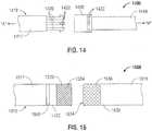
- Tube coupling mechanism 1400is configured to releasably engage first and second components 1417, 1418 of shaft 1412 to one another. More specifically, tube coupling mechanism 1400 includes a plurality of cantilever arms 1420 disposed radially about longitudinal axis "A-A" and extending distally from one of the shaft components, e.g., first shaft component 1417, and a plurality of complementary-shaped recesses 1432 defined within hub 1430 of the other shaft component, e.g., second shaft component 1418.
- tabs 1422 extending from cantilever arms 1420are configured for engagement within recesses 1432 of hub 1430 upon approximation of first and second shaft components 1417, 1418, respectively, to engage first and second shaft components 1417, 1418 to one another.
- tube coupling mechanism 1500(not part of the invention) is configured to releasably engage first and second shaft components 1517, 1518, respectively, of shaft 1512 to one another.
- One of the shaft componentse.g., first shaft component 1517
- the other shaft componente.g., second shaft component 1518
- a receiving portion 1530disposed at proximal end 1532 thereof that is configured to receive insertion portion 1520 therein for releasably engaging first and second shaft component 1517, 1518, respectively, to one another.
- a release ring 1540is disposed on first shaft component 1517 and is longitudinally slidable thereabout to permit disengagement of first and second shaft components 1517, 1518, as will be described below.
- insertion portion 1520 of first shaft component 1517defines a diameter that is slightly smaller than a diameter of lumen 1534 of receiving portion 1530 of second shaft component 1518 to permit insertion of insertion portion 1520 into lumen 1534 of receiving portion 1530 and to retain insertion portion 1520 in engagement within receiving portion 1530 via friction-fitting. Further, insertion portion 1520 defines a textured outer peripheral surface 1524 configured to facilitate engagement of insertion portion 1520 within lumen 1534 of receiving portion 1530.
- Receiving portion 1530 of second shaft component 1518defines a generally cylindrical configuration and is formed from a helically-wound braid, e.g., a biaxial braid, of material. Due to this braided configuration, receiving portion 1530 is elongated and constricted, i.e., the length of receiving portion 1530 is increased and the diameter of lumen 1534 is reduced, upon axial extension of receiving portion 1530. Receiving portion 1530 is normally disposed in an at-rest position, wherein receiving portion 1530 defines a relatively smaller length and wherein lumen 1534 defines a relatively larger diameter as compared to the extended position.
- a helically-wound braide.g., a biaxial braid
- insertion portion 1520is inserted into lumen 1534 of receiving portion 1530.
- textured outer peripheral surface 1524 of insertion portion 1520facilitates the frictional engagement of insertion portion 1520 of first shaft component 1517 within receiving portion 1530 of second shaft component 1518.
- removal of insertion portion 1520 from receiving portion 1530is inhibited by the braided-configuration of receiving portion 1530. More specifically, attempted withdrawal of insertion portion 1520 causes axial extension of receiving portion 1530 which, in turn, constricts, or reduces the diameter of lumen 1534 of receiving portion 1530. Accordingly, receiving portion 1530 is constricted about insertion portion 1520, thereby increasing the frictional engagement therebetween and inhibiting withdrawal of insertion portion 1520 from receiving portion 1530.
- release ring 1540is slid distally over first shaft component 1517 into position abutting the proximal end of receiving portion 1530 of second shaft components 1518. Thereafter, while maintaining release ring 1540 in position abutting receiving portion 1530, first shaft component 1517 is translated proximally relative to second shaft component 1518 to withdraw insertion portion 1520 from receiving portion 1530, thereby disengaging first and second shaft component 1517, 1518, respectively, from one another.
- Release ring 1540inhibits extension of receiving portion 1530 during withdrawal of first shaft component 1517 such that the diameter of lumen 1534 of receiving portion 1530 is maintained. In other words, release ring 1540 inhibits extension and constriction of receiving portion 1530, thus permitting disengagement of of first and second shaft components 1517, 1518, respectively, from one another.
Landscapes
- Health & Medical Sciences (AREA)
- Surgery (AREA)
- Life Sciences & Earth Sciences (AREA)
- Engineering & Computer Science (AREA)
- Biomedical Technology (AREA)
- Public Health (AREA)
- Nuclear Medicine, Radiotherapy & Molecular Imaging (AREA)
- Veterinary Medicine (AREA)
- General Health & Medical Sciences (AREA)
- Heart & Thoracic Surgery (AREA)
- Medical Informatics (AREA)
- Molecular Biology (AREA)
- Animal Behavior & Ethology (AREA)
- Physics & Mathematics (AREA)
- Otolaryngology (AREA)
- Plasma & Fusion (AREA)
- Ophthalmology & Optometry (AREA)
- Surgical Instruments (AREA)
Description
- The present disclosure relates to surgical instruments and, more particularly, to coupling mechanisms for surgical instruments having separable and/or replaceable components.
- A forceps is a plier-like instrument which relies on mechanical action between its jaws to grasp, clamp and constrict vessels or tissue. Electrosurgical forceps utilize both mechanical clamping action and electrical energy to affect hemostasis by heating tissue and blood vessels to coagulate and/or cauterize tissue. Certain surgical procedures require more than simply cauterizing tissue and rely on the unique combination of clamping pressure, precise electrosurgical energy control and gap distance (i.e., distance between opposing jaw members when closed about tissue) to "seal" tissue, vessels and certain vascular bundles. Typically, once a vessel is sealed, the surgeon has to accurately sever the vessel along the newly formed tissue seal. Accordingly, many vessel sealing instruments have been designed which incorporate a knife or blade member which effectively severs the tissue after forming a tissue seal.
- Generally, surgical instruments, including forceps, can be classified as single-use instruments, e.g., instruments that are discarded after a single use, partially-reusable instruments, e.g., instruments including both disposable portions and portions that are sterilizable for reuse, and completely reusable instruments, e.g., instruments that are completely sterilizable for repeated use. As can be appreciated, those instruments (or components of instruments) that can be sterilized and reused help reduce the costs associated with the particular surgical procedure for which they are used. However, although reusable surgical instruments are cost-effective, it is important that these instruments be capable of performing the same functions as their disposable counterparts, that any disposable components of these instruments be efficiently removable and replaceable with new components, and that the reusable components be efficiently and satisfactorily sterilizable for reuse.
US5893875 discloses a surgical instrument on which the preamble of the independent claim is based.- As used herein, the term "distal" refers to the portion that is being described which is further from a user, while the term "proximal" refers to the portion that is being described which is closer to a user.
- Any of the aspects disclosed herein, to the extent they are consistent, may be used in conjunction with any of the other aspects disclosed herein.
- In accordance with one aspect of the present disclosure, a surgical instrument is provided as recited in claim 1 with preferred features as set forth in the dependent claims. The surgical instrument includes a shaft defining a longitudinal axis therethrough and having an end effector assembly disposed at a distal end thereof. The shaft includes first and second shaft components that are releasably engageable with one another. A drive sleeve is disposed within the shaft and is longitudinally translatable relative to the shaft to transition the end effector assembly between a first state and a second state. The drive sleeve also includes first and second drive sleeve components that are releasably engageable with one another. A coupling mechanism includes one or more shaft cantilever springs and one or more drive sleeve cantilever springs that are coupled to the one or more shaft cantilever springs. The shaft cantilever springs are configured to engage the first shaft component at a first end thereof and the second shaft component at a second end thereof to releasably engage the first and second shaft components to one another. Similarly, the drive sleeve cantilever springs are configured to engage the first drive sleeve component at a first end thereof and the second drive sleeve component at a second end thereof to releasably engage the first and second drive sleeve components to one another.
- The shaft cantilever spring includes a tab configured to bias into an aperture in one of the first and second shaft components in a releasable way to releasably engage the first and second shaft components to one another. The shaft cantilever springs include a first tab disposed at the first end thereof and extending therefrom and a second tab disposed at the second end thereof and extending thereform. The first tab and second tabs are configured to bias into engagement within apertures defined within the first and second shaft components, respectively, to engage the first and second shaft components to one another. The drive sleeve cantilever spring may include a first tab configured to bias into engagement with an aperture in one of the first and second drive sleeve components in a releasable way to releasably engage the first and second drive sleeve components to one another. Further, the drive sleeve cantilever springs may also include a first tab disposed at the first end thereof and extending therefrom and a second tab disposed at the second end thereof and extending thereform. The first tab and second tabs are configured to bias into engagement within apertures defined within the first and second drive components, respectively, to engage the first and second drive sleeve components to one another.
- In another aspect, the shaft cantilever spring and the drive sleeve cantilever spring are coupled to one another via a break-away feature. The break-away feature is configured to break, decoupling the shaft cantilever spring and the drive sleeve cantilever spring from one another to permit the drive sleeve to translate relative to the shaft.
- The end effector assembly may include first and second jaw members. The first state may be a closed state of the jaw members and the second state may be an open state of the jaw members. The end effector assembly may be for grasping and perhaps also for electrosurgically treating e.g. sealing, tissue.
- In still another aspect, a knife assembly is disposed within the drive sleeve. The knife assembly includes a knife bar having a knife disposed at a distal end of the knife bar. The knife bar is longitudinally translatable through the shaft and relative to the end effector assembly to translate the knife between a retracted position and an extended position for cutting tissue.
- In yet another aspect, the surgical instrument further includes a knife assembly disposed within the drive sleeve. The knife assembly includes a knife bar having a knife disposed at a distal end of the knife bar and is longitudinally translatable through the shaft and relative to the end effector assembly to translate the knife between a retracted position and an extended position for cutting tissue.
- Various aspects of the present disclosure are described herein with reference to the drawings wherein like reference numerals identify similar or identical elements:
Fig. 1 is a side, perspective view of one embodiment of a surgical instrument provided in accordance with the present disclosure wherein the shaft of the instrument is in an assembled condition;Fig. 2A is a longitudinal, cross-sectional view of the surgical instrument ofFig. 1 wherein an end effector assembly is disposed in a spaced-apart position;- Fig. 28 is a longitudinal, cross-sectional view of the surgical instrument of
Fig. 1 wherein the end effector assembly is disposed in an approximated position and wherein a knife blade is disposed in a retracted position; Fig. 2C is a longitudinal, cross-sectional view of the surgical instrument ofFig. 1 wherein the end effector assembly is disposed in an approximated position and wherein the knife blade is disposed in an extended position;Fig. 3 is an enlarged, side view of a distal end of the surgical instrument ofFig. 1 , wherein the shaft of the instrument is in a decoupled condition;Fig. 4 is a transverse, cross-sectional view of the surgical instrument ofFig. 3 taken across section line 4-4;Fig. 5A is a side, cross-sectional view of one embodiment of a shaft coupling mechanism provided in accordance with the present disclosure wherein the shaft is in a decoupled condition;- Fig. 58 is a side, cross-sectional view of the shaft coupling mechanism of
Fig. 5A wherein the shaft is in an assembled condition; Fig. 6A is a side, cross-sectional view ofan example of a shaft coupling mechanism (not claimed) provided in accordance with the present disclosure wherein the shaft is in a decoupled condition;- Fig. 68 is a side, cross-sectional view of the shaft coupling mechanism of
Fig. 6A during assembly of the shaft; Fig. 6C is a side, cross-sectional view of the shaft coupling mechanism ofFig. 6A , wherein the shaft is in an assembled condition;Fig. 6D is a top view of one of the shaft components of the shaft ofFig. 6A ;Fig. 6E is a transverse, cross-sectional view taken alongsection line 6E-6E ofFig. 6C ;Fig. 7A is a side view of another example (not claimed) of a shaft coupling mechanism provided in accordance with the present disclosure wherein the shaft is in a decoupled condition;- Fig. 78 is a side view of the shaft coupling mechanism of
Fig. 7A wherein the shaft is in an assembled condition; Fig. 8 is a side, perspective view of yet another example (not claimed) of a shaft coupling mechanism provided in accordance with the present disclosure wherein the shaft is in a decoupled condition;Fig. 9 is a side view of still yet another example (not claimed) of a shaft coupling mechanism provided in accordance with the present disclosure wherein the shaft is in a decoupled condition;Fig. 10 is a side view of another example (not claimed) of a shaft coupling mechanism provided in accordance with the present disclosure wherein the shaft is in a decoupled condition;Fig. 11 is a side view of another example (not claimed) of a shaft coupling mechanism provided in accordance with the present disclosure wherein the shaft is in a decoupled condition;Fig. 12 is a side view of another example (not claimed) of a shaft coupling mechanism provided in accordance with the present disclosure wherein the shaft is in a decoupled condition;Fig. 13 is a side, cross-sectional view of still another example (not claimed) of a shaft coupling mechanism provided in accordance with the present disclosure wherein the shaft is in a decoupled condition;Fig. 14 is a side view of yet another example (not claimed) of a shaft coupling mechanism provided in accordance with the present disclosure wherein the shaft is in a decoupled condition; andFig. 15 is a side view of still yet another example (not claimed) of a shaft coupling mechanism provided in accordance with the present disclosure wherein the shaft is in a decoupled condition.- Referring now to
Fig. 1 , aforceps 10 for use in connection with endoscopic surgical procedures is shown, althoughforceps 10 may also be configured for use in connection with traditional open surgical procedures.Forceps 10 defines a longitudinal axis "A-A" and includes ahousing 20, ahandle assembly 30, a trigger assembly 70, a rotatingassembly 80, and anend effector assembly 100.End effector assembly 100 includes first andsecond jaw members Fig. 1 ) and an approximated position (Fig. 8B ) for grasping tissue therebetween.Forceps 10 further includes ashaft 12 having adistal end 14 configured to mechanically engageend effector assembly 100 and aproximal end 16 that mechanically engageshousing 20. Forceps 10 also includes anelectrosurgical cable 310 that connectsforceps 10 to a generator (not shown) or other suitable power source, althoughforceps 10 may alternatively be configured as a battery powered instrument.Cable 310 includes a wire (or wires) (not explicitly shown) extending therethrough, intohousing 20 and throughshaft 12 to ultimately connect the source of electrosurgical energy (not explicitly shown) tojaw member 110 and/orjaw member 120 ofend effector assembly 100. However, any other suitable electrical connection(s) for supplying energy tojaw member 110 and/orjaw member 120 may also be provided.- With continued reference to
Fig. 1 , handleassembly 30 includes a fixedhandle 50 and amoveable handle 40. Fixedhandle 50 is integrally associated withhousing 20 and handle 40 is moveable relative to fixedhandle 50. Rotatingassembly 80 is rotatable in either direction about a longitudinal axis "A-A" to rotateend effector 100 about longitudinal axis "A-A." Thehousing 20 houses the internal working components of theforceps 10. End effector assembly 100 is attached at adistal end 14 ofshaft 12 and includes a pair of opposingjaw members End effector assembly 100 is designed as a unilateral assembly, i.e., wherejaw member 120 is fixed relative toshaft 12 andjaw member 110 is moveable relative to bothshaft 12 and fixedjaw member 120. However,end effector assembly 100 may alternatively be configured as a bilateral assembly, i.e., where bothjaw member 110 andjaw member 120 are moveable relative to one another and with respect toshaft 12.- As shown in
Fig. 1 , eachjaw member tissue sealing plate Tissue sealing plates jaw members jaw members Figs. 2A-2C ) is disposed withinshaft 12 and aknife channel 115, 125 (Figs. 2A-2C ) is defined within one or both oftissue sealing plates jaw members Figs. 2A-2C ) therethrough for cutting tissue grasped betweenjaw members Figs. 2A-2C ) between a retracted position (seeFigs. 2A-2B ), wherein knife 184 (Figs. 2A-2C ) is disposed withinshaft 12, and an extended position (seeFig. 2C ), wherein knife 184 (Figs. 2A-2C ) extends betweenjaw members - Continuing with reference to
Fig. 1 ,moveable handle 40 ofhandle assembly 30 is ultimately connected to a drive assembly including a drive sleeve 60 (Fig. 4 ) that, together, mechanically cooperate to impart movement ofjaw members plates jaw members Fig. 1 ,moveable handle 40 is initially spaced-apart from fixedhandle 50 and, correspondingly,jaw members Moveable handle 40 is depressible from this initial position to a depressed position corresponding to the approximated position ofjaw members 110, 120 (seeFigs. 2B-2C ). With tissue grasped betweentissue sealing plates jaw members tissue sealing plates activation switch 90, to seal tissue disposed betweenjaw members - With reference now to
Figs. 2A-2C , in conjunction withFig. 1 , drivesleeve 60 is disposed withinshaft 12 and is coupled tojaw member 110 at the distal end thereof such that, asdrive sleeve 60 is translated proximally throughshaft 12 and relative tojaw member 120, e.g., via depressingmovable handle 40,jaw member 110 is pulled to pivot from the spaced-apart position (Fig. 2A ) to the approximated position (Figs. 2B, 2C ). On the other hand, whendrive sleeve 60 is translated distally, e.g., via releasing or returningmovable handle 40 to its initial position,jaw member 110 is urged to pivot from the approximated position (Figs. 2B, 2C ) back to the spaced-apart position (Fig. 2A ). However, this configuration may be reversed, e.g., where proximal translation ofdrive sleeve 60 movesjaw members drive sleeve 60 movesjaw members - Continuing with reference to
Figs. 2A-2C ,shaft 12 further includes aknife assembly 180 disposed therein.Knife assembly 180 is disposed withindrive sleeve 60 and includes aknife bar 182 havingknife 184 coupled thereto at the proximal end of 185 ofknife 184.Knife 184 defines acutting blade 186 atdistal end 187 thereof.Knife 184 is translatable between a retracted position (Figs. 2A-2B ), whereinknife 184 is disposed withinshaft 12, and an extended position (Fig. 2C ), whereinknife 184 extends throughknife channels jaw members jaw members Fig. 1 ) of trigger assembly 70 (Fig. 1 ),knife bar 182 is advanced distally throughshaft 12 and drivesleeve 60 to urgeknife 184 from the retracted position to the extended position. Further,knife assembly 180 may be biased, e.g., via a spring (not explicitly shown), toward the retracted position such that, upon release oftrigger 72,knife 184 is automatically returned to the retracted position. - Turning now to
Figs. 3-4 , in conjunction withFigs. 1-2C ,shaft 12 offorceps 10 is separable, or decouplable into first andsecond shaft sections second section 18 ofshaft 12, includingend effector assembly 100, is removable from the remainder offorceps 10, thus allowingsecond section 18 ofshaft 12 andend effector assembly 100 to be replaced with new components after each use (or each procedure), or to be cleaned, sterilized, or otherwise prepared for reuse independently of the remaining components offorceps 10. Such a configuration also permits the use of various different end effector assemblies withforceps 10 by simply selecting the desired end effector assembly and coupling that end effector assembly and thesecond shaft section 18 thereof tofirst section 17 ofshaft 12. - Put more generally, the replaceable distal portion, e.g.,
second shaft section 18 andend effector assembly 100, offorceps 10 helps reduce the equipment costs associated with performing a particular surgical procedure by obviating the need to provide an entire new surgical instrument, facilities sterilization and cleaning of the components of the instrument by providing greater access to the components of the instrument and allowing different components of the instrument to be cleaned and/or sterilized via different procedures, and increases the versatility of the instrument by allowing different shaft components and/or end effectors to be coupled thereto. - However, while it is advantageous to provide a surgical instrument, e.g.,
forceps 10, that includes ashaft 12 that is separable into first andshaft sections second shaft sections shaft 12. More specifically, as best shown inFig. 4 ,shaft 12 defines an outer tube, or lumen that houses drivesleeve 60. Drivesleeve 60, as mentioned above, is selectively translatable through and relative toshaft 12 to pivotjaw member 110 relative tojaw member 120 between the spaced-apart and approximated positions. Drivesleeve 60 also includesknife bar 182 disposed therein that, as described above, is selectively translatable relative to drivesleeve 60 andshaft 12 to advanceknife 184 from the retracted position to the extended position to cut tissue grasped betweenjaw members shaft 12 to connect the source of electrosurgical energy (not explicitly shown) tojaw member 110 and/orjaw member 120 ofend effector assembly 100 for providing energizing end effector assembly. - Various embodiment of coupling mechanisms configured to releasably couple the first and
second sections shaft 12 to one another in accordance with those considerations addressed above will be described in detail below with reference toFigs. 5A-15 . More particularly, the coupling mechanisms described hereinbelow may be configured for coupling the first andsecond sections shaft 12, the components ofdrive sleeve 60, and/or the components ofknife bar 182 to one another, as well as for re-establishing and electrical connections extending throughshaft 12. Further, the various coupling mechanisms described hereinbelow may be used alone or in combination with one another to releasably couple one or more of the respective components ofshaft 12,drive sleeve 60, and/orknife bar 182 to one another. Thus, while certain coupling mechanisms may be shown and described with reference to only a single connection, e.g., for coupling the first andsecond sections shaft 12 to one another, such mechanisms (or other coupling mechanisms) may also be used for further coupling the other components, e.g., first and second sections of thedrive sleeve 60 and/orknife bar 182, to one another. Likewise, the electrical connections described hereinbelow in connection with some embodiments of coupling mechanisms for electrically coupling the first andsecond sections shaft 12 to one another such that electrosurgical energy may be supplied fromhousing 20 to endeffector assembly 100 may also be used in conjunction with any of the other coupling mechanisms described herein. - Additionally, although the embodiments herein are described with reference to a
forceps 10, the presently disclosed coupling mechanisms may be used in conjunction with any shafted surgical instrument (including single or multiple component shafts) having an end effector assembly disposed at one end and a handle, housing, grip, control, etc. disposed at the other end. Further, the attachment point of first andsecond sections shaft 12 may be disposed at various positions along the length ofshaft 12, e.g., closer towardsdistal end 14 such thatsecond section 18 defines a greater length thanfirst portion 17, closer towardproximal end 16 such thatfirst section 17 defines a greater length thanfirst portion 17, or anywhere betweenproximal end 16 anddistal end 14 ofshaft 12. - Referring now to
Figs. 5A-5B , one embodiment of a tube coupling mechanism for coupling first andsecond components shaft 512 to one another as well as for coupling first andsecond components drive sleeve 560 to one another is shown generally identified byreference numeral 500.Tube coupling mechanism 500 includes two sets of cantilever springs 520, 530 and 570, 580. Eachcantilever spring arm first tab first end second tab second end First tabs apertures second component 518 ofshaft 512, whilesecond tabs apertures first component 517 ofshaft 512. More specifically, as will be described below, cantilever springs 520, 530 are configured to resiliently biassecond tabs respective apertures first component 517 upon insertion intoshaft 512 to engage first andsecond components shaft 512 to one another. - Each
cantilever spring arm first tab first end second tab second end 577, 587, respectively, thereof.First tabs apertures second component 568 ofdrive sleeve 560, while cantilever springs 570, 580 are configured to resiliently biassecond tabs respective apertures 566, 568 offirst component 567 ofdrive sleeve 560 upon positioning aboutdrive sleeve 560 to engage first andsecond components drive sleeve 560 to one another. Further, cantilever springs 520, 570 may be coupled, engaged, or otherwise formed to one another adjacentfirst end 525 ofcantilever spring 520 andsecond end 577 ofcantilever spring 570 via a break-away feature, orcoupling 549. Cantilever springs 530, 580 may likewise be coupled, engaged, or otherwise formed to one another adjacentfirst end 535 ofcantilever spring 530 and second end 587 ofcantilever spring 580 via a break-away feature, orcoupling 599. - With continued reference to
Figs. 5A-5B , in order to couple first andsecond components shaft 512 to one another and first andsecond components drive sleeve 560 to one another, first andsecond component shaft 512 are brought into approximation with one another. As can be appreciated, approximation of first andsecond component shaft 512 likewise approximates first andsecond components drive sleeve 560 due to the engagement of cantilever springs 520, 570 and 530, 580 via break-awaycouplings second component shaft 512 are brought into approximation with one another,second tabs lumen 514 defined throughshaft 512. On the other hand,second tabs drive sleeve 560. - As first and
second components shaft 512 are further approximated relative to one another,second tabs lumen 514 ofshaft 512 into positionadjacent apertures first component 517, whereby cantilever springs 520, 530 are resiliently biased back to their initial, un-flexed position, thus urgingsecond tabs apertures second components shaft 512 to one another. Similarly,second tabs first component 567 ofdrive sleeve 560 into positionadjacent apertures first component 567, whereby cantilever springs 570, 580 are resiliently biased back to their initial, un-flexed position, thus urgingsecond tabs apertures second components drive sleeve 560 to one another. - With first and
second components shaft 512 engaged to one another and with first andsecond components drive sleeve 560 engaged to one another,drive sleeve 560 may be translated relative toshaft 512 an initial time, e.g., via depressing movable handle 40 (Fig. 1 ), to break, tear, or otherwise destroy break-awaycouplings couplings drive sleeve 560 is free to translate throughlumen 514 and relative toshaft 512 for movingjaw members 110, 120 (Fig. 1 ) between the spaced-apart and approximated positions. - In order to decouple
shaft components tabs tabs apertures tabs apertures shaft components shaft component second components drive sleeve 560 may similarly be decoupled from one another. - Turning now to
Figs. 6A-6E , an example (not claimed) of a tube coupling mechanism is shown generally identified viareference numeral 600.Tube coupling mechanism 600 is configured to releasably engage first andsecond components shaft 612 to one another. More specifically,tube coupling mechanism 600 includes a pair ofresilient locking tabs second component 618 and extending outwardly therefrom (although lockingtabs shaft component 617 to extend inwardly therefrom). As best shown inFig. 6A , in an at-rest position, lockingtabs second shaft component 618. Eachlocking tab free end tabs second shaft component 618.First shaft component 617, on the other hand, includes a pair ofapertures tabs first shaft component 617 may define a slightly larger diameter thansecond shaft component 618 such thatsecond shaft component 618 may be inserted at least partially intolumen 614 offirst shaft component 617 to couple first andsecond shaft components - With continued reference to
Figs. 6A-6E , in order to engage first andsecond shaft components second shaft component 618 is inserted intolumen 614 defined throughfirst shaft component 617. Assecond shaft component 618 is urged intolumen 614 offirst shaft component 617,resilient locking tabs second shaft component 618 in order to permit passage ofsecond shaft component 618 intolumen 614 offirst shaft component 617, as best shown inFig. 6B . - As
second shaft component 618 is translated further throughlumen 614 offirst shaft components 617tabs adjacent apertures first shaft component 617, wherebytabs tabs apertures second components shaft 612 to one another. Similarly as described above, in order to decoupleshaft components tabs tabs apertures tabs apertures second shaft component 618 may be removed fromlumen 614 offirst shaft component 617 to decoupleshaft component - Turning now to
Figs. 7A-7B , another example of a tube coupling mechanism (not claimed) is shown generally identified byreference numeral 700.Tube coupling mechanism 700 is configured to engage first andsecond shaft component shaft 712 to one another. One of the shaft components, e.g.,first shaft component 717, includes aninsertion portion 720 extending fromend 722 thereof, while the other shaft component, e.g.,second shaft component 718, includes a receivingportion 730 disposed atend 732 thereof.Insertion portion 720 is configured for insertion intolumen 734 of receivingportion 730 for securing first andsecond shaft components - As shown in
Fig. 7A ,insertion portion 720 offirst shaft component 717 defines a diameter that is smaller relative to the diameter of receivingportion 730 ofshaft component 718, such thatinsertion portion 720 may be inserted intolumen 734 of receivingportion 730 untilends second shaft components insertion portion 720 and/or receivingportion 730 are transitioned from this first condition, wherein the diameter ofinsertion portion 720 is smaller than the diameter of receivingportion 730, to a second, or engaged condition, whereininsertion portion 720 is retained in engagement within receivingportion 730 via friction-fitting. As can be appreciated, in the engaged condition, the diameters ofinsertion portion 720 and receivingportion 730 may be substantially similar to one another to retain first andsecond shaft components - In order to engage
insertion portion 720 and receivingportion 730 to one another, one or both of theportions insertion portion 720 in inserted into receivingportion 730; and, finally,insertion portion 720 and/or receivingportion 730 are transitioned to the engaged condition to engage first andsecond shaft components portion 730 ofsecond shaft component 718 may be heated to an expanded state (i.e., the first condition) such thatinsertion portion 720 offirst shaft component 717 may be inserted intolumen 734 of receivingportion 730. Thereafter, receivingportion 730 is cooled, or allowed to cool, such that receivingportion 730 is contracted aboutinsertion portion 720 back to its initial condition to engageinsertion portion 720 therein. - Alternatively,
insertion portion 720 and receivingportion 730 may be formed from materials having different coefficients of expansion such that bothinsertion portion 720 and receivingportion 730 may be heated to permitinsertion portion 720 to be inserted into receivingportion 730. Thereafter, bothinsertion portion 720 and receivingportion 730 are allowed to cool, or are cooled, back to their initial states to engageinsertion portion 720 within receivingportion 730.Insertion portion 720 and/or receivingportion 730 may also be formed form shape memory materials, or may include thermal or electric bimetal materials disposed thereon to facilitate transitioning ofinsertion portion 720 and receivingportion 730 between the first and second conditions for securing first andsecond shaft components - In order to decouple first and
second shaft components insertion portion 720 and receivingportion 730 are transitioned, e.g., heated, to once again achieve the first condition, thus allowing first andsecond shaft components insertion portion 720 is removed fromlumen 734 of receivingportion 730. Fig. 8 shows another example (not claimed) of ashaft coupling mechanism 800 that is configured to releasably engage first andsecond shaft components shaft 812 to one another.Shaft coupling mechanism 800 generally includes atab 820 disposed on and extending from an outer periphery of one of the shaft components, e.g.,second shaft component 818, and aslot 830 defined within the outer periphery of the other shaft component, e.g.,first shaft component 817.Slot 830 includes alongitudinal segment 836 having an opendistal end 837 atdistal end 832 offirst shaft component 817 and alocking segment 840 in communication withlongitudinal segment 836 atproximal end 838 thereof. Lockingsegment 840 includes atransverse portion 842 extending in substantially-transverse relation relative tolongitudinal segment 836, and a distally-extending tab-retainingportion 844 in communication therewith.First shaft component 817 further includes a biasing member, e.g., aspring 848 disposed withinlumen 834 thereof, the importance of which will be described below.- With continued reference to
Fig. 8 ,second shaft component 818 defines a diameter smaller than that offirst shaft component 817 to permit passage ofsecond shaft component 818 intolumen 834 offirst shaft component 817. Further,tab 820 ofsecond shaft component 818 is configured to be received within, and to translate throughslot 830 offirst shaft component 817 to engage first andsecond shaft components - In order to engage first and
second shaft components second shaft component 818 is inserted intolumen 834 offirst shaft component 817 such thattab 820 is inserted intolongitudinal segment 836 ofslot 830 via opendistal end 837 thereof. Assecond shaft component 818 is translated further intolumen 834 offirst shaft component 817,tab 820 is translated proximally alonglongitudinal segment 836 ofslot 830 towardsproximal end 838 thereof. However, prior totab 820 reachingproximal end 838 oflongitudinal segment 836 ofslot 830,proximal end 822 ofsecond shaft component 818contacts biasing member 848. As such, in order to translatesecond shaft component 818 further throughlumen 834 offirst shaft component 817,second shaft component 818 must be urged sufficiently to overcome the bias of biasingmember 848. - Eventually,
second shaft component 818 is translated proximally, against the bias of biasingmember 848, such thattab 820 is disposed atproximal end 838 oflongitudinal segment 836 ofslot 830. Once this position is achieved,second shaft component 818 is rotated about longitudinal axis "A-A" relative tofirst shaft component 817 such thattab 820 is translated alongtransverse portion 842 of lockingsegment 840 into position adjacent tab-retainingportion 844 of lockingsegment 840 ofslot 830. Thereafter,second shaft component 818 may be released, allowing biasingmember 848 to biassecond shaft component 818 distally such thattab 820 is translated distally into tab-retainingportion 844 of lockingsegment 840 ofslot 830 to engage first andsecond shaft components - In order to disengage first and
second shaft components second shaft component 818 is translated proximally relative tofirst shaft component 817 such thattab 820 is translated proximally from tab-retainingportion 844 of lockingsegment 840 intotransverse portion 842 of lockingsegment 840 ofslot 830. Thereafter,second shaft component 818 is rotated relative tofirst shaft component 817 about longitudinal axis "A-A" such thattab 820 is once again aligned withlongitudinal segment 836 ofslot 830 so thatsecond shaft component 818 can be translated distally and removed fromfirst shaft component 817, thereby decoupling first andsecond shaft components - Referring now to
Fig. 9 ,shaft coupling mechanism 900 is configured to engage first andsecond shaft components shaft 912 to one another.Shaft coupling mechanism 900 includes afirst hub 920 disposed on one of the shaft components, e.g.,first shaft component 917, and asecond hub 930 disposed on the other shaft component, e.g.,second shaft component 918. More specifically,first hub 920 extends fromdistal end 922 offirst shaft component 917 and defines a reduced diameter relative tofirst shaft component 917 such that a distally-facingshoulder 924 is defined therebetween. Further,first hub 920 includes ahelical track 926 defined within an outer periphery thereof, thehelical track 926 including an opendistal end 927 and a retainingnotch 928 formed atproximal end 929 thereof. An O-ring 940, or other suitable resilient biasing member, is disposed aboutfirst hub 920adjacent shoulder 924. Second hub 930 extends fromproximal end 932 ofsecond shaft component 918 and defines alumen 934 extending therethrough that is configured to receivefirst hub 920 offirst shaft component 917 therein.Second hub 930 further includes atab 936 disposed on an inner surface thereof and extending inwardly intolumen 934.Tab 936 is configured to be received within, and to translate throughtrack 926 offirst hub 920.- In use, to couple first and
second shaft components second shaft components first hub 920 extends partially intosecond hub 930 such thattab 936 enters opendistal end 927 oftrack 926. Withtab 936 positioned withintrack 926,second shaft component 918 is rotated relative tofirst shaft component 917 about longitudinal axis "A-A" such thattab 936 is translated proximally throughtrack 926, thereby further engagingfirst hub 920 withinsecond hub 930. Upon further rotation ofsecond shaft component 918 relative tofirst shaft component 917 and, thus, upon further translation offirst hub 920 intosecond hub 930,tab 936 is translated throughtrack 926 into positionadjacent retaining notch 928 oftrack 926. However, in this position,second hub 930 is positioned adjacent O-ring 940. Thus, in order to translatetab 936 intonotch 928,second shaft component 918 is rotated with sufficient urging to compress O-ring 940, thus permitting further proximal translation oftab 936 throughhelical track 926. Ultimately, oncetab 936 has reachednotch 928,second shaft component 918 may be released, allowing O-ring 940 to resiliently return to its at rest condition such thatsecond shaft component 918 is biased distally and, thus,tab 936 is biased into engagement withinnotch 928 to engage first andsecond shaft components - In order to decouple first and
second shaft components second shaft component 918 is translated proximally relative tofirst shaft component 917 such thatsecond shaft component 918 is urged against first O-ring 940 to compress O-ring 940, allowingsecond shaft component 918 to translate further proximally. In this position,tab 936 ofsecond shaft component 918 is once again aligned withhelical track 926 such thatsecond shaft component 918 may be rotated about longitudinal axis "A-A" to translatetab 936 distally throughhelical track 926, ultimately disengaging first andsecond shaft components Fig. 10 shows another example (not claimed) embodiment of ashaft coupling mechanism 1000 configured for releasably engaging first andsecond shaft components shaft 1012 to one another.Shaft coupling mechanism 1000 includes afirst hub 1020 disposed on one of the shaft components, e.g.,first shaft component 1017, and asecond hub 1030 disposed on the other shaft component, e.g.,second shaft component 1018.Shaft coupling mechanism 1000 further includes asleeve 1050 slidably disposed aboutshaft 1012, the importance of which will be describe below.First hub 1020 ofshaft coupling mechanism 1000 extends fromdistal end 1022 offirst shaft component 1017 and defines a pair ofopposed notches 1024 within the outer periphery thereof. Alternatively, rather thannotches 1024, an annular groove (not shown) may be defined therein. An 0-ring 1040, or other suitable biasing member is disposed aboutfirst shaft component 1017 and is disposed within each ofnotches 1024.Second hub 1030 extends fromproximal end 1032 ofsecond shaft component 1018 and defines alumen 1034 extending therethrough that is configured to receivefirst hub 1020 offirst shaft component 1017 therein.Second hub 1030 further includes a pair of opposed cantilever springs 1036 extending proximally therefrom. Each of the cantilever springs 1036 defines atab 1038 at a free end thereof.Tabs 1038 extend inwardly toward one another and are configured for engagement withinnotches 1024 offirst hub 1020. Alternatively, rather than a pair ofopposed cantilever spring 1036,second hub 1030 may include an annular biasing member (not shown) configured for engagement within an annular groove (not shown) defined withinfirst hub 1020.- First and
second hubs electrical connection members first hub 1020, may include afemale connection member 1060, while the other hub, e.g.,second hub 1030, includes amale connection member 1070 configured for insertion intofemale connection member 1060 to electrically couple first andsecond shaft components Fig. 1 ). - In order to engage first and
second components shaft 1012 to one another, first andsecond component shaft 1012 are brought into approximation with one another. As first andsecond components shaft 1012 are brought into approximation with one another,tabs 1038 ofcantilever springs 1036 are flexed outwardly, i.e., apart from one another, to permit passagefirst hub 1020 intolumen 1034 ofsecond hub 1030. - As
first hub 1020 is inserted further intolumen 1034 ofsecond hub 1030,tabs 1038 are translated proximally along the outer periphery offirst hub 1020. Eventually,tabs 1030 are translated into positionadjacent notches 1024 defined withinfirst hub 1020. Once disposedadjacent notches 1024, the resilient biasing force of cantilever springs 1036 urgestabs 1038 inwardly back toward their initial position such thattabs 1038 are engaged withinnotches 1024, thereby engaging first andsecond shaft components 1017, 1718 to one another. O-ring 1040, which is also disposed withinnotches 1024,biases tabs 1038 into frictional engagement withinnotches 1024, ensuring sufficiently engagement therebetween. Translation offirst hub 1020 further intolumen 1034 ofsecond hub 1030 also translatesmale connection member 1070 into engagement withfemale connection member 1060 to electrically couple first andsecond shaft components - With first and
second shaft components sleeve 1050 may be slid distally aboutshaft 1012 to substantially surround first andsecond hubs sleeve 1050 disposed about first andsecond hubs sleeve 1050 helps maintain the engagement between first andsecond shaft components - In order to disengage first and
second shaft components sleeve 1050 is first slid proximally (or distally) such thatsleeve 1050 is no longer disposed about first andsecond hubs tabs 1038 are disengaged fromnotches 1024 and first andsecond shaft components second shaft components Fig. 11 shows another example (not claimed) embodiment of atube coupling mechanism 1100 configured to releasably engage first andsecond components shaft 1112 to one another.Shaft components lumen lumens Figs. 2A-2C ) and/or knife bar 182 (Figs. 2A-2C ) therethrough to facilitate movingjaw members 110,
120 (Figs. 2A-2C ) between the spaced-apart position and the approximated position and for translating knife 184 (Figs. 2A-2C ) between the retracted position and the extend position, respectively.- With continued reference to
Fig. 11 , one of the shaft components, e.g.,first shaft component 1117, includes a pair ofpins 1020 extending distally therefrom, while the other shaft components, e.g., second shaft component 118 includes a pair of apertures 1130 defined therethrough.Pins 1020 andapertures 1030 are radially-spaced fromlumens shaft 1112.Pins 1020 are configured to be inserted intoapertures 1030 to secure first and second shaft components to one another. More specifically, pins 1020 define a substantially similar, or slightly smaller, diameter than that ofapertures 1030 to facilitate friction-fitting engagement between first andsecond shaft components apertures 1030 may also include a resilient material disposed on the internal surface thereof. In such an embodiment, pins 1020 and/orapertures 1030 are configured to be compressed upon insertion ofpins 1030 and/orapertures 1030 to resiliently bias first andsecond shaft components - Turning now to
Fig. 12 , yet another example (not claimed) of a tube coupling mechanism configured for engaging first andsecond shaft components shaft 1212 to one another is shown generally identified byreference numeral 1200. One of the shaft components, e.g.,first shaft component 1217, includes amale connection member 1220 extending distally fromdistal end 1222 therefrom, while the other shaft component, e.g.,second shaft component 1218, includes a recess, orfemale connection member 1230 defined therein atproximal end 1232 thereof.Male connection member 1220 and/orfemale connection member 1230 are shaped complementary to one another to facilitate engagement therebetween for engaging first andsecond shaft components male connection member 1220 may include an adhesive disposed on an outer peripheral surface thereof (or may be formed from an adhesive material) and/orfemale connection member 1230 may include an adhesive disposed on an inner surface thereof (or may be formed from an adhesive material) to facilitate engagement therebetween. More specifically, the adhesive may include UV-activated adhesives, heat-activated adhesives, pressure-activated adhesives, gamma ray-activated adhesives, solvent adhesives, or other suitable adhesives. Alternatively, temporary welding may be used to secure first andsecond shaft components components - With reference now to
Fig. 13 , tube coupling mechanism 1300 (not part of the invention) is shown configured for releasably engaging first andsecond shaft components shaft 1312 to one another.Tube coupling mechanism 1300 includes one ormore magnets first shaft component 1317 and one ormore magnets second shaft component 1318.Magnets magnets shaft components magnets magnets second shaft components Fig. 13 ,magnets magnets second shaft components - Referring now to
Fig. 14 , another example (not claimed) of a tube coupling mechanism is shown generally identified viareference numeral 1400.Tube coupling mechanism 1400 is configured to releasably engage first andsecond components shaft 1412 to one another. More specifically,tube coupling mechanism 1400 includes a plurality ofcantilever arms 1420 disposed radially about longitudinal axis "A-A" and extending distally from one of the shaft components, e.g.,first shaft component 1417, and a plurality of complementary-shapedrecesses 1432 defined withinhub 1430 of the other shaft component, e.g.,second shaft component 1418. Similarly as described above with respect to previous embodiments,tabs 1422 extending from cantilever arms
1420 are configured for engagement withinrecesses 1432 ofhub 1430 upon approximation of first andsecond shaft components second shaft components - Turning now to
Fig. 15 , tube coupling mechanism 1500 (not part of the invention) is configured to releasably engage first andsecond shaft components shaft 1512 to one another. One of the shaft components, e.g.,first shaft component 1517, includes aninsertion portion 1520 extending fromdistal end 1522 thereof, while the other shaft component, e.g.,second shaft component 1518, includes a receivingportion 1530 disposed atproximal end 1532 thereof that is configured to receiveinsertion portion 1520 therein for releasably engaging first andsecond shaft component release ring 1540 is disposed onfirst shaft component 1517 and is longitudinally slidable thereabout to permit disengagement of first andsecond shaft components - Continuing with reference to
Fig. 15 ,insertion portion 1520 offirst shaft component 1517 defines a diameter that is slightly smaller than a diameter oflumen 1534 of receivingportion 1530 ofsecond shaft component 1518 to permit insertion ofinsertion portion 1520 intolumen 1534 of receivingportion 1530 and to retaininsertion portion 1520 in engagement within receivingportion 1530 via friction-fitting. Further,insertion portion 1520 defines a textured outerperipheral surface 1524 configured to facilitate engagement ofinsertion portion 1520 withinlumen 1534 of receivingportion 1530. - Receiving
portion 1530 ofsecond shaft component 1518 defines a generally cylindrical configuration and is formed from a helically-wound braid, e.g., a biaxial braid, of material. Due to this braided configuration, receivingportion 1530 is elongated and constricted, i.e., the length of receivingportion 1530 is increased and the diameter oflumen 1534 is reduced, upon axial extension of receivingportion 1530. Receivingportion 1530 is normally disposed in an at-rest position, wherein receivingportion 1530 defines a relatively smaller length and whereinlumen 1534 defines a relatively larger diameter as compared to the extended position. - In use, in order to engage first and
second shaft components insertion portion 1520 is inserted intolumen 1534 of receivingportion 1530. In this position, textured outerperipheral surface 1524 ofinsertion portion 1520 facilitates the frictional engagement ofinsertion portion 1520 offirst shaft component 1517 within receivingportion 1530 ofsecond shaft component 1518. Further, removal ofinsertion portion 1520 from receivingportion 1530 is inhibited by the braided-configuration of receivingportion 1530. More specifically, attempted withdrawal ofinsertion portion 1520 causes axial extension of receivingportion 1530 which, in turn, constricts, or reduces the diameter oflumen 1534 of receivingportion 1530. Accordingly, receivingportion 1530 is constricted aboutinsertion portion 1520, thereby increasing the frictional engagement therebetween and inhibiting withdrawal ofinsertion portion 1520 from receivingportion 1530. - In order to disengage first and
second shaft components release ring 1540 is slid distally overfirst shaft component 1517 into position abutting the proximal end of receivingportion 1530 ofsecond shaft components 1518. Thereafter, while maintainingrelease ring 1540 in position abutting receivingportion 1530,first shaft component 1517 is translated proximally relative tosecond shaft component 1518 to withdrawinsertion portion 1520 from receivingportion 1530, thereby disengaging first andsecond shaft component Release ring 1540 inhibits extension of receivingportion 1530 during withdrawal offirst shaft component 1517 such that the diameter oflumen 1534 of receivingportion 1530 is maintained. In other words,release ring 1540 inhibits extension and constriction of receivingportion 1530, thus permitting disengagement of of first andsecond shaft components - From the foregoing and with reference to the various figure drawings, those skilled in the art will appreciate that certain modifications can also be made to the present disclosure without departing from the scope of the same. While several embodiments of the disclosure have been shown in the drawings, it is not intended that the disclosure be limited thereto, as it is intended that the disclosure be as broad in scope as the art will allow and that the specification be read likewise. Therefore, the above description should not be construed as limiting, but merely as exemplifications of particular embodiments. Those skilled in the art will envision other modifications within the scope of the claims appended hereto.
Claims (4)
- A surgical instrument (10), comprising:a shaft (512) defining a longitudinal axis therethrough and having an end effector assembly (100) disposed at a distal end thereof, the shaft including first and second shaft sections (517, 518) that are releasably engageable with one another;a drive sleeve (560) disposed within the shaft and longitudinally translatable relative to the shaft to transition the end effector assembly between a first state and a second state, the drive sleeve including first and second drive sleeve sections (567, 568) that are releasably engageable with one another; anda coupling mechanism (500) including:at least one shaft cantilever spring (520, 530), the shaft cantilever spring configured to engage the first shaft component (517) at a first end thereof and configured to engage the second shaft section (518) at a second end thereof to releasably engage the first and second shaft sections to one another; andcharacterised byat least one drive sleeve cantilever spring (570, 580) coupled to the at least one shaft cantilever spring (520, 530), the drive sleeve cantilever spring configured to engage the first drive sleeve section (567) at a first end thereof and configured to engage the second drive sleeve section (568) at a second end thereof to releasably engage the first and second drive sleeve sections to one another,wherein the shaft cantilever spring includes a first tab (524, 534) disposed at the first end thereof and extending therefrom and a second tab (526, 536) disposed at the second end thereof and extending thereform, the first tab and second tabs configured to bias into engagement within apertures (542, 544, 546, 548) defined within the first and second shaft sections, respectively, to engage the first and second shaft sections to one another.
- The surgical instrument according to claim 1, wherein the drive sleeve cantilever spring includes a first tab (574, 584) disposed at the first end thereof and extending therefrom and a second tab (546, 586) disposed at the second end thereof and extending thereform, the first tab and second tabs configured to bias into engagement within apertures (592, 594, 596, 598) defined within the first and second drives sections, respectively, to engage the first and second drive sleeve sections to one another.
- The surgical instrument according to claim 1 or 2, wherein the shaft cantilever spring and the drive sleeve cantilever spring are coupled to one another via a break-away feature, the break-away feature configured to break, decoupling the shaft cantilever spring and the drive sleeve cantilever spring from one another to permit the drive sleeve to translate relative to the shaft.
- The surgical instrument according to claim 1, 2 or 3, further comprising:a knife assembly (182, 186) disposed within the drive sleeve, the knife assembly including a knife bar (182) having a knife (186) disposed at a distal end of the knife bar, the knife bar longitudinally translatable through the shaft and relative to the end effector assembly to translate the knife between a retracted position and an extended position for cutting tissue.
Applications Claiming Priority (1)
| Application Number | Priority Date | Filing Date | Title |
|---|---|---|---|
| US13/306,523US9113899B2 (en) | 2011-11-29 | 2011-11-29 | Coupling mechanisms for surgical instruments |
Publications (3)
| Publication Number | Publication Date |
|---|---|
| EP2599447A2 EP2599447A2 (en) | 2013-06-05 |
| EP2599447A3 EP2599447A3 (en) | 2015-08-19 |
| EP2599447B1true EP2599447B1 (en) | 2017-10-18 |
Family
ID=47257562
Family Applications (1)
| Application Number | Title | Priority Date | Filing Date |
|---|---|---|---|
| EP12193997.9ANot-in-forceEP2599447B1 (en) | 2011-11-29 | 2012-11-23 | Coupling mechanisms for surgical instruments |
Country Status (2)
| Country | Link |
|---|---|
| US (3) | US9113899B2 (en) |
| EP (1) | EP2599447B1 (en) |
Families Citing this family (168)
| Publication number | Priority date | Publication date | Assignee | Title |
|---|---|---|---|---|
| US7364577B2 (en) | 2002-02-11 | 2008-04-29 | Sherwood Services Ag | Vessel sealing system |
| ES2262639T3 (en) | 2001-04-06 | 2006-12-01 | Sherwood Services Ag | SHUTTER AND DIVIDER OF GLASSES WITH BUMPER MEMBERS N OCONDUCTIVES. |
| US7628791B2 (en) | 2005-08-19 | 2009-12-08 | Covidien Ag | Single action tissue sealer |
| US8298232B2 (en) | 2006-01-24 | 2012-10-30 | Tyco Healthcare Group Lp | Endoscopic vessel sealer and divider for large tissue structures |
| AU2008302043B2 (en) | 2007-09-21 | 2013-06-27 | Covidien Lp | Surgical device |
| US8357158B2 (en) | 2008-04-22 | 2013-01-22 | Covidien Lp | Jaw closure detection system |
| US8465502B2 (en) | 2008-08-25 | 2013-06-18 | Covidien Lp | Surgical clip applier and method of assembly |
| US9358015B2 (en) | 2008-08-29 | 2016-06-07 | Covidien Lp | Endoscopic surgical clip applier with wedge plate |
| US8114122B2 (en) | 2009-01-13 | 2012-02-14 | Tyco Healthcare Group Lp | Apparatus, system, and method for performing an electrosurgical procedure |
| US8187273B2 (en) | 2009-05-07 | 2012-05-29 | Tyco Healthcare Group Lp | Apparatus, system, and method for performing an electrosurgical procedure |
| US8430876B2 (en) | 2009-08-27 | 2013-04-30 | Tyco Healthcare Group Lp | Vessel sealer and divider with knife lockout |
| US8357159B2 (en) | 2009-09-03 | 2013-01-22 | Covidien Lp | Open vessel sealing instrument with pivot assembly |
| US8133254B2 (en) | 2009-09-18 | 2012-03-13 | Tyco Healthcare Group Lp | In vivo attachable and detachable end effector assembly and laparoscopic surgical instrument and methods therefor |
| US8112871B2 (en) | 2009-09-28 | 2012-02-14 | Tyco Healthcare Group Lp | Method for manufacturing electrosurgical seal plates |
| US8403945B2 (en) | 2010-02-25 | 2013-03-26 | Covidien Lp | Articulating endoscopic surgical clip applier |
| US8968337B2 (en) | 2010-07-28 | 2015-03-03 | Covidien Lp | Articulating clip applier |
| US9844384B2 (en) | 2011-07-11 | 2017-12-19 | Covidien Lp | Stand alone energy-based tissue clips |
| US8864795B2 (en) | 2011-10-03 | 2014-10-21 | Covidien Lp | Surgical forceps |
| US9364231B2 (en) | 2011-10-27 | 2016-06-14 | Covidien Lp | System and method of using simulation reload to optimize staple formation |
| US8968309B2 (en) | 2011-11-10 | 2015-03-03 | Covidien Lp | Surgical forceps |
| US9113899B2 (en) | 2011-11-29 | 2015-08-25 | Covidien Lp | Coupling mechanisms for surgical instruments |
| US8968310B2 (en) | 2011-11-30 | 2015-03-03 | Covidien Lp | Electrosurgical instrument with a knife blade lockout mechanism |
| US8968360B2 (en) | 2012-01-25 | 2015-03-03 | Covidien Lp | Surgical instrument with resilient driving member and related methods of use |
| US8747434B2 (en) | 2012-02-20 | 2014-06-10 | Covidien Lp | Knife deployment mechanisms for surgical forceps |
| US8961514B2 (en)* | 2012-03-06 | 2015-02-24 | Covidien Lp | Articulating surgical apparatus |
| US9375282B2 (en) | 2012-03-26 | 2016-06-28 | Covidien Lp | Light energy sealing, cutting and sensing surgical device |
| US9265569B2 (en) | 2012-03-29 | 2016-02-23 | Covidien Lp | Method of manufacturing an electrosurgical forceps |
| US9820765B2 (en) | 2012-05-01 | 2017-11-21 | Covidien Lp | Surgical instrument with stamped double-flange jaws |
| US9668807B2 (en) | 2012-05-01 | 2017-06-06 | Covidien Lp | Simplified spring load mechanism for delivering shaft force of a surgical instrument |
| US8968311B2 (en) | 2012-05-01 | 2015-03-03 | Covidien Lp | Surgical instrument with stamped double-flag jaws and actuation mechanism |
| US9375258B2 (en) | 2012-05-08 | 2016-06-28 | Covidien Lp | Surgical forceps |
| US9039731B2 (en) | 2012-05-08 | 2015-05-26 | Covidien Lp | Surgical forceps including blade safety mechanism |
| US9510891B2 (en)* | 2012-06-26 | 2016-12-06 | Covidien Lp | Surgical instruments with structures to provide access for cleaning |
| US9192421B2 (en) | 2012-07-24 | 2015-11-24 | Covidien Lp | Blade lockout mechanism for surgical forceps |
| US9265566B2 (en) | 2012-10-16 | 2016-02-23 | Covidien Lp | Surgical instrument |
| US9421014B2 (en) | 2012-10-18 | 2016-08-23 | Covidien Lp | Loading unit velocity and position feedback |
| US9216013B2 (en) | 2013-02-18 | 2015-12-22 | Covidien Lp | Apparatus for endoscopic procedures |
| USD788302S1 (en) | 2013-10-01 | 2017-05-30 | Covidien Lp | Knife for endoscopic electrosurgical forceps |
| US9974540B2 (en)* | 2013-10-18 | 2018-05-22 | Covidien Lp | Adapter direct drive twist-lock retention mechanism |
| US20150150574A1 (en)* | 2013-12-04 | 2015-06-04 | Covidien Lp | Adapter direct drive push button retention mechanism |
| US9918713B2 (en) | 2013-12-09 | 2018-03-20 | Covidien Lp | Adapter assembly for interconnecting electromechanical surgical devices and surgical loading units, and surgical systems thereof |
| CN105813582B (en) | 2013-12-11 | 2019-05-28 | 柯惠Lp公司 | Wrist and jaw assemblies for robotic surgical systems |
| CN110448377A (en) | 2013-12-12 | 2019-11-15 | 柯惠Lp公司 | Gear train for robotic surgical system |
| US20150173944A1 (en)* | 2013-12-23 | 2015-06-25 | Novartis Ag | Systems and methods for attaching a surgical instrument tip |
| US10219869B2 (en) | 2014-02-12 | 2019-03-05 | Covidien Lp | Surgical end effectors and pulley assemblies thereof |
| EP3125785B1 (en) | 2014-03-31 | 2020-03-04 | Covidien LP | Wrist and jaw assemblies for robotic surgical systems |
| US20150351828A1 (en)* | 2014-06-05 | 2015-12-10 | Covidien Lp | Surgical instrument including re-usable portion |
| US9763661B2 (en) | 2014-06-26 | 2017-09-19 | Covidien Lp | Adapter assembly for interconnecting electromechanical surgical devices and surgical loading units, and surgical systems thereof |
| US10039592B2 (en) | 2014-09-17 | 2018-08-07 | Covidien Lp | Deployment mechanisms for surgical instruments |
| US9877777B2 (en) | 2014-09-17 | 2018-01-30 | Covidien Lp | Surgical instrument having a bipolar end effector assembly and a deployable monopolar assembly |
| US9918785B2 (en) | 2014-09-17 | 2018-03-20 | Covidien Lp | Deployment mechanisms for surgical instruments |
| US9987076B2 (en) | 2014-09-17 | 2018-06-05 | Covidien Lp | Multi-function surgical instruments |
| US10080605B2 (en) | 2014-09-17 | 2018-09-25 | Covidien Lp | Deployment mechanisms for surgical instruments |
| US10603128B2 (en) | 2014-10-07 | 2020-03-31 | Covidien Lp | Handheld electromechanical surgical system |
| US10226254B2 (en) | 2014-10-21 | 2019-03-12 | Covidien Lp | Adapter, extension, and connector assemblies for surgical devices |
| US10729443B2 (en) | 2014-10-21 | 2020-08-04 | Covidien Lp | Adapter, extension, and connector assemblies for surgical devices |
| US10085750B2 (en) | 2014-10-22 | 2018-10-02 | Covidien Lp | Adapter with fire rod J-hook lockout |
| US10111665B2 (en) | 2015-02-19 | 2018-10-30 | Covidien Lp | Electromechanical surgical systems |
| US10190888B2 (en) | 2015-03-11 | 2019-01-29 | Covidien Lp | Surgical stapling instruments with linear position assembly |
| US10226239B2 (en) | 2015-04-10 | 2019-03-12 | Covidien Lp | Adapter assembly with gimbal for interconnecting electromechanical surgical devices and surgical loading units, and surgical systems thereof |
| US10327779B2 (en) | 2015-04-10 | 2019-06-25 | Covidien Lp | Adapter, extension, and connector assemblies for surgical devices |
| US11432902B2 (en) | 2015-04-10 | 2022-09-06 | Covidien Lp | Surgical devices with moisture control |
| US11278286B2 (en) | 2015-04-22 | 2022-03-22 | Covidien Lp | Handheld electromechanical surgical system |
| EP3741309A1 (en) | 2015-04-22 | 2020-11-25 | Covidien LP | Handheld electromechanical surgical system |
| US10881408B2 (en)* | 2015-04-22 | 2021-01-05 | Covidien Lp | Interlock assembly for replaceable loading units |
| US20180110560A1 (en)* | 2015-05-11 | 2018-04-26 | Zamenis Surgical Llc | Minimally invasive surgical devices |
| USD844139S1 (en) | 2015-07-17 | 2019-03-26 | Covidien Lp | Monopolar assembly of a multi-function surgical instrument |
| USD844138S1 (en) | 2015-07-17 | 2019-03-26 | Covidien Lp | Handle assembly of a multi-function surgical instrument |
| US10751058B2 (en) | 2015-07-28 | 2020-08-25 | Covidien Lp | Adapter assemblies for surgical devices |
| AU2016326371B2 (en) | 2015-09-25 | 2020-07-23 | Covidien Lp | Robotic surgical assemblies and instrument drive connectors thereof |
| US10371238B2 (en) | 2015-10-09 | 2019-08-06 | Covidien Lp | Adapter assembly for surgical device |
| US10413298B2 (en) | 2015-10-14 | 2019-09-17 | Covidien Lp | Adapter assembly for surgical devices |
| US10292705B2 (en) | 2015-11-06 | 2019-05-21 | Covidien Lp | Surgical apparatus |
| US10939952B2 (en) | 2015-11-06 | 2021-03-09 | Covidien Lp | Adapter, extension, and connector assemblies for surgical devices |
| US10617411B2 (en) | 2015-12-01 | 2020-04-14 | Covidien Lp | Adapter assembly for surgical device |
| US10433841B2 (en) | 2015-12-10 | 2019-10-08 | Covidien Lp | Adapter assembly for surgical device |
| US10265130B2 (en)* | 2015-12-11 | 2019-04-23 | Ethicon Llc | Systems, devices, and methods for coupling end effectors to surgical devices and loading devices |
| US10420554B2 (en) | 2015-12-22 | 2019-09-24 | Covidien Lp | Personalization of powered surgical devices |
| US10253847B2 (en) | 2015-12-22 | 2019-04-09 | Covidien Lp | Electromechanical surgical devices with single motor drives and adapter assemblies therfor |
| US10524797B2 (en) | 2016-01-13 | 2020-01-07 | Covidien Lp | Adapter assembly including a removable trocar assembly |
| US10660623B2 (en) | 2016-01-15 | 2020-05-26 | Covidien Lp | Centering mechanism for articulation joint |
| US10508720B2 (en) | 2016-01-21 | 2019-12-17 | Covidien Lp | Adapter assembly with planetary gear drive for interconnecting electromechanical surgical devices and surgical loading units, and surgical systems thereof |
| US10398439B2 (en) | 2016-02-10 | 2019-09-03 | Covidien Lp | Adapter, extension, and connector assemblies for surgical devices |
| CA2958160A1 (en) | 2016-02-24 | 2017-08-24 | Covidien Lp | Endoscopic reposable surgical clip applier |
| US10537381B2 (en) | 2016-02-26 | 2020-01-21 | Covidien Lp | Surgical instrument having a bipolar end effector assembly and a deployable monopolar assembly |
| WO2017151887A1 (en) | 2016-03-04 | 2017-09-08 | Covidien Lp | Coupler assembly for coupling surgical instruments to robotic systems |
| US10799239B2 (en) | 2016-05-09 | 2020-10-13 | Covidien Lp | Adapter assembly with pulley system and worm gear drive for interconnecting electromechanical surgical devices and surgical end effectors |
| US10736637B2 (en) | 2016-05-10 | 2020-08-11 | Covidien Lp | Brake for adapter assemblies for surgical devices |
| US10588610B2 (en) | 2016-05-10 | 2020-03-17 | Covidien Lp | Adapter assemblies for surgical devices |
| US10702302B2 (en) | 2016-05-17 | 2020-07-07 | Covidien Lp | Adapter assembly including a removable trocar assembly |
| US10463374B2 (en) | 2016-05-17 | 2019-11-05 | Covidien Lp | Adapter assembly for a flexible circular stapler |
| EP3463143A4 (en) | 2016-05-26 | 2020-01-22 | Covidien LP | ROBOTIC SURGICAL ARRANGEMENTS |
| US11141162B2 (en)* | 2016-07-08 | 2021-10-12 | Covidien Lp | Loading unit locking collar with linearly actuated release |
| US11890070B2 (en)* | 2016-07-14 | 2024-02-06 | Intuitive Surgical Operations, Inc. | Instrument release |
| US10653398B2 (en) | 2016-08-05 | 2020-05-19 | Covidien Lp | Adapter assemblies for surgical devices |
| US10631887B2 (en) | 2016-08-15 | 2020-04-28 | Covidien Lp | Electrosurgical forceps for video assisted thoracoscopic surgery and other surgical procedures |
| US11213389B2 (en)* | 2016-10-17 | 2022-01-04 | Lsi Solutions, Inc. | Prosthetic suturing device and methods thereof |
| US10492795B2 (en) | 2016-11-01 | 2019-12-03 | Covidien Lp | Endoscopic surgical clip applier |
| US11116594B2 (en) | 2016-11-08 | 2021-09-14 | Covidien Lp | Surgical systems including adapter assemblies for interconnecting electromechanical surgical devices and end effectors |
| US10813695B2 (en) | 2017-01-27 | 2020-10-27 | Covidien Lp | Reflectors for optical-based vessel sealing |
| US11583291B2 (en) | 2017-02-23 | 2023-02-21 | Covidien Lp | Endoscopic surgical clip applier |
| US10631945B2 (en) | 2017-02-28 | 2020-04-28 | Covidien Lp | Autoclavable load sensing device |
| US11272929B2 (en) | 2017-03-03 | 2022-03-15 | Covidien Lp | Dynamically matching input and output shaft speeds of articulating adapter assemblies for surgical instruments |
| US10299790B2 (en) | 2017-03-03 | 2019-05-28 | Covidien Lp | Adapter with centering mechanism for articulation joint |
| US10660641B2 (en) | 2017-03-16 | 2020-05-26 | Covidien Lp | Adapter with centering mechanism for articulation joint |
| US10390858B2 (en) | 2017-05-02 | 2019-08-27 | Covidien Lp | Powered surgical device with speed and current derivative motor shut off |
| US11324502B2 (en) | 2017-05-02 | 2022-05-10 | Covidien Lp | Surgical loading unit including an articulating end effector |
| US10603035B2 (en) | 2017-05-02 | 2020-03-31 | Covidien Lp | Surgical loading unit including an articulating end effector |
| US10675043B2 (en) | 2017-05-04 | 2020-06-09 | Covidien Lp | Reposable multi-fire surgical clip applier |
| US10973567B2 (en) | 2017-05-12 | 2021-04-13 | Covidien Lp | Electrosurgical forceps for grasping, treating, and/or dividing tissue |
| US11172980B2 (en) | 2017-05-12 | 2021-11-16 | Covidien Lp | Electrosurgical forceps for grasping, treating, and/or dividing tissue |
| USD854684S1 (en) | 2017-06-08 | 2019-07-23 | Covidien Lp | Open vessel sealer with mechanical cutter |
| USD843574S1 (en) | 2017-06-08 | 2019-03-19 | Covidien Lp | Knife for open vessel sealer |
| USD854149S1 (en) | 2017-06-08 | 2019-07-16 | Covidien Lp | End effector for open vessel sealer |
| US11154348B2 (en) | 2017-08-29 | 2021-10-26 | Covidien Lp | Surgical instruments and methods of assembling surgical instruments |
| US11583358B2 (en) | 2017-09-06 | 2023-02-21 | Covidien Lp | Boundary scaling of surgical robots |
| EP3678579A4 (en) | 2017-09-08 | 2021-06-16 | Covidien LP | Energy disconnect for robotic surgical assemblies |
| US11376015B2 (en) | 2017-11-03 | 2022-07-05 | Covidien Lp | Endoscopic surgical clip applier and handle assemblies for use therewith |
| EP3737328B1 (en) | 2018-01-09 | 2025-04-30 | Covidien LP | STERILE INTERFACE MODULE FOR ROBOTIC SURGICAL DEVICES |
| US11241275B2 (en) | 2018-03-21 | 2022-02-08 | Covidien Lp | Energy-based surgical instrument having multiple operational configurations |
| WO2019191015A1 (en) | 2018-03-29 | 2019-10-03 | Covidien Lp | Robotic surgical systems and instrument drive assemblies |
| US11123132B2 (en) | 2018-04-09 | 2021-09-21 | Covidien Lp | Multi-function surgical instruments and assemblies therefor |
| US11160556B2 (en) | 2018-04-23 | 2021-11-02 | Covidien Lp | Threaded trocar for adapter assemblies |
| US10780544B2 (en) | 2018-04-24 | 2020-09-22 | Covidien Lp | Systems and methods facilitating reprocessing of surgical instruments |
| US10828756B2 (en) | 2018-04-24 | 2020-11-10 | Covidien Lp | Disassembly methods facilitating reprocessing of multi-function surgical instruments |
| US10993721B2 (en)* | 2018-04-25 | 2021-05-04 | Covidien Lp | Surgical clip applier |
| US11534172B2 (en) | 2018-05-07 | 2022-12-27 | Covidien Lp | Electromechanical surgical stapler including trocar assembly release mechanism |
| US11896230B2 (en) | 2018-05-07 | 2024-02-13 | Covidien Lp | Handheld electromechanical surgical device including load sensor having spherical ball pivots |
| US11399839B2 (en) | 2018-05-07 | 2022-08-02 | Covidien Lp | Surgical devices including trocar lock and trocar connection indicator |
| US20190388091A1 (en) | 2018-06-21 | 2019-12-26 | Covidien Lp | Powered surgical devices including strain gauges incorporated into flex circuits |
| US11241233B2 (en) | 2018-07-10 | 2022-02-08 | Covidien Lp | Apparatus for ensuring strain gauge accuracy in medical reusable device |
| US12029507B2 (en) | 2018-07-26 | 2024-07-09 | Covidien Lp | Surgical robotic systems |
| US11596496B2 (en) | 2018-08-13 | 2023-03-07 | Covidien Lp | Surgical devices with moisture control |
| US11076858B2 (en) | 2018-08-14 | 2021-08-03 | Covidien Lp | Single use electronics for surgical devices |
| US11510669B2 (en) | 2020-09-29 | 2022-11-29 | Covidien Lp | Hand-held surgical instruments |
| US11376062B2 (en) | 2018-10-12 | 2022-07-05 | Covidien Lp | Electrosurgical forceps |
| US11471211B2 (en) | 2018-10-12 | 2022-10-18 | Covidien Lp | Electrosurgical forceps |
| US11717276B2 (en) | 2018-10-30 | 2023-08-08 | Covidien Lp | Surgical devices including adapters and seals |
| US11350982B2 (en) | 2018-12-05 | 2022-06-07 | Covidien Lp | Electrosurgical forceps |
| US11523861B2 (en) | 2019-03-22 | 2022-12-13 | Covidien Lp | Methods for manufacturing a jaw assembly for an electrosurgical forceps |
| US11241228B2 (en) | 2019-04-05 | 2022-02-08 | Covidien Lp | Surgical instrument including an adapter assembly and an articulating surgical loading unit |
| US11426168B2 (en) | 2019-07-05 | 2022-08-30 | Covidien Lp | Trocar coupling assemblies for a surgical stapler |
| US11446035B2 (en) | 2019-06-24 | 2022-09-20 | Covidien Lp | Retaining mechanisms for trocar assemblies |
| US11464541B2 (en) | 2019-06-24 | 2022-10-11 | Covidien Lp | Retaining mechanisms for trocar assembly |
| US11123101B2 (en) | 2019-07-05 | 2021-09-21 | Covidien Lp | Retaining mechanisms for trocar assemblies |
| US12402934B2 (en) | 2019-09-15 | 2025-09-02 | Covidien Lp | Electrosurgical instrument for grasping, treating, and/or dividing tissue incorporating thermal management feature |
| DE102019129462A1 (en)* | 2019-10-31 | 2021-05-06 | Karl Storz Se & Co. Kg | Medical instrument that can be dismantled |
| US11737747B2 (en) | 2019-12-17 | 2023-08-29 | Covidien Lp | Hand-held surgical instruments |
| US11583275B2 (en) | 2019-12-27 | 2023-02-21 | Covidien Lp | Surgical instruments including sensor assembly |
| US11779340B2 (en) | 2020-01-02 | 2023-10-10 | Covidien Lp | Ligation clip loading device |
| US11622804B2 (en) | 2020-03-16 | 2023-04-11 | Covidien Lp | Forceps with linear trigger mechanism |
| US12114866B2 (en) | 2020-03-26 | 2024-10-15 | Covidien Lp | Interoperative clip loading device |
| US11504117B2 (en) | 2020-04-02 | 2022-11-22 | Covidien Lp | Hand-held surgical instruments |
| US12016557B2 (en) | 2020-06-10 | 2024-06-25 | Covidien Lp | Sealed electrical connection between surgical loading unit and adapter |
| US12295641B2 (en) | 2020-07-01 | 2025-05-13 | Covidien Lp | Electrosurgical forceps with swivel action nerve probe |
| US11660109B2 (en) | 2020-09-08 | 2023-05-30 | Covidien Lp | Cutting elements for surgical instruments such as for use in robotic surgical systems |
| US11660091B2 (en) | 2020-09-08 | 2023-05-30 | Covidien Lp | Surgical device with seal assembly |
| US12185964B2 (en) | 2020-09-10 | 2025-01-07 | Covidien Lp | End effector assemblies for surgical instruments such as for use in robotic surgical systems |
| US12161386B2 (en) | 2020-09-11 | 2024-12-10 | Covidien Lp | Surgical instruments having an articulating section such as for use in robotic surgical systems |
| US11925406B2 (en) | 2020-09-14 | 2024-03-12 | Covidien Lp | End effector assemblies for surgical instruments |
| US11571192B2 (en) | 2020-09-25 | 2023-02-07 | Covidien Lp | Adapter assembly for surgical devices |
| CN114533248A (en)* | 2020-11-24 | 2022-05-27 | 上海逸思医疗科技股份有限公司 | Detachable surgical operation instrument |
| CN113180784B (en)* | 2021-04-29 | 2022-02-01 | 西安交通大学医学院第一附属医院 | Non-destructive laparoscope grasping forceps with scissors function |
| DE102021112975B4 (en)* | 2021-05-19 | 2023-03-02 | Karl Storz Se & Co. Kg | Endoscopic instrument and shaft and instrument insert for an endoscopic instrument |
| US11786248B2 (en) | 2021-07-09 | 2023-10-17 | Covidien Lp | Surgical stapling device including a buttress retention assembly |
| CN113456141A (en)* | 2021-08-09 | 2021-10-01 | 苏州美东汇成精密部件有限公司 | Active bending system of anastomat |
| GB2609637B (en)* | 2021-08-10 | 2023-10-04 | Gyrus Medical Ltd | Surgical device seal |
| DE102021134277A1 (en)* | 2021-12-22 | 2023-06-22 | Karl Storz Se & Co. Kg | medical instrument |
Family Cites Families (169)
| Publication number | Priority date | Publication date | Assignee | Title |
|---|---|---|---|---|
| SU401367A1 (en) | 1971-10-05 | 1973-10-12 | Тернопольский государственный медицинский институт | BIAKTIVNYE ELECTRO SURGICAL INSTRUMENT |
| DE2415263A1 (en) | 1974-03-29 | 1975-10-02 | Aesculap Werke Ag | Surgical H.F. coagulation probe has electrode tongs - with exposed ends of insulated conductors forming tong-jaws |
| DE2514501A1 (en) | 1975-04-03 | 1976-10-21 | Karl Storz | Bipolar coagulation instrument for endoscopes - has two high frequency electrodes looped over central insulating piece |
| FR2315286A2 (en) | 1975-06-26 | 1977-01-21 | Lamidey Marcel | H.F. blood coagulating dissecting forceps - with adjustable stops to vary clamping space and circuit making contacts |
| US4071029A (en)* | 1976-05-21 | 1978-01-31 | Stryker Corporation | Angle handpiece |
| USD249549S (en) | 1976-10-22 | 1978-09-19 | Aspen Laboratories, Inc. | Electrosurgical handle |
| DE2855682A1 (en)* | 1978-12-22 | 1980-07-03 | Siemens Ag | DEVICE FOR DETACHABLY CONNECTING TWO AXIAL TOGETHER WITH DENTAL DENTAL HANDPIECE OR THE LIKE. -SHARE |
| USD263020S (en) | 1980-01-22 | 1982-02-16 | Rau Iii David M | Retractable knife |
| US4671274A (en) | 1984-01-30 | 1987-06-09 | Kharkovsky Nauchno-Issledovatelsky Institut Obschei I | Bipolar electrosurgical instrument |
| DE3423356C2 (en) | 1984-06-25 | 1986-06-26 | Berchtold Medizin-Elektronik GmbH & Co, 7200 Tuttlingen | Electrosurgical high frequency cutting instrument |
| US4657016A (en) | 1984-08-20 | 1987-04-14 | Garito Jon C | Electrosurgical handpiece for blades, needles and forceps |
| USD299413S (en) | 1985-07-17 | 1989-01-17 | The Stanley Works | Folding pocket saw handle |
| USD295893S (en) | 1985-09-25 | 1988-05-24 | Acme United Corporation | Disposable surgical clamp |
| USD295894S (en) | 1985-09-26 | 1988-05-24 | Acme United Corporation | Disposable surgical scissors |
| USD298353S (en) | 1986-05-06 | 1988-11-01 | Vitalmetrics, Inc. | Handle for surgical instrument |
| DE8712328U1 (en) | 1987-09-11 | 1988-02-18 | Jakoubek, Franz, 7201 Emmingen-Liptingen | Endoscopy forceps |
| JP2806511B2 (en) | 1990-07-31 | 1998-09-30 | 松下電工株式会社 | Manufacturing method of sintered alloy |
| US5389102A (en) | 1990-09-13 | 1995-02-14 | United States Surgical Corporation | Apparatus and method for subcuticular stapling of body tissue |
| US5190541A (en) | 1990-10-17 | 1993-03-02 | Boston Scientific Corporation | Surgical instrument and method |
| JP2951418B2 (en) | 1991-02-08 | 1999-09-20 | トキコ株式会社 | Sample liquid component analyzer |
| US5330471A (en) | 1991-06-07 | 1994-07-19 | Hemostatic Surgery Corporation | Bi-polar electrosurgical endoscopic instruments and methods of use |
| US5391166A (en)* | 1991-06-07 | 1995-02-21 | Hemostatic Surgery Corporation | Bi-polar electrosurgical endoscopic instruments having a detachable working end |
| USD348930S (en) | 1991-10-11 | 1994-07-19 | Ethicon, Inc. | Endoscopic stapler |
| JPH0630945A (en) | 1992-05-19 | 1994-02-08 | Olympus Optical Co Ltd | Suturing apparatus |
| US5478351A (en) | 1992-06-24 | 1995-12-26 | Microsurge, Inc. | Endoscopic surgical tool with handle and detachable tool assembly |
| USD349341S (en) | 1992-10-28 | 1994-08-02 | Microsurge, Inc. | Endoscopic grasper |
| DE4303882C2 (en) | 1993-02-10 | 1995-02-09 | Kernforschungsz Karlsruhe | Combination instrument for separation and coagulation for minimally invasive surgery |
| JP3390041B2 (en) | 1993-04-05 | 2003-03-24 | オリンパス光学工業株式会社 | Forceps |
| GB9309142D0 (en) | 1993-05-04 | 1993-06-16 | Gyrus Medical Ltd | Laparoscopic instrument |
| USD343453S (en) | 1993-05-05 | 1994-01-18 | Laparomed Corporation | Handle for laparoscopic surgical instrument |
| USD354564S (en) | 1993-06-25 | 1995-01-17 | Richard-Allan Medical Industries, Inc. | Surgical clip applier |
| US5792165A (en)* | 1993-07-21 | 1998-08-11 | Charles H. Klieman | Endoscopic instrument with detachable end effector |
| US5688270A (en) | 1993-07-22 | 1997-11-18 | Ethicon Endo-Surgery,Inc. | Electrosurgical hemostatic device with recessed and/or offset electrodes |
| US5693051A (en) | 1993-07-22 | 1997-12-02 | Ethicon Endo-Surgery, Inc. | Electrosurgical hemostatic device with adaptive electrodes |
| GB9322464D0 (en) | 1993-11-01 | 1993-12-22 | Gyrus Medical Ltd | Electrosurgical apparatus |
| USD358887S (en) | 1993-12-02 | 1995-05-30 | Cobot Medical Corporation | Combined cutting and coagulating forceps |
| DE4403252A1 (en) | 1994-02-03 | 1995-08-10 | Michael Hauser | Instrument shaft for min. invasive surgery |
| GB9413070D0 (en) | 1994-06-29 | 1994-08-17 | Gyrus Medical Ltd | Electrosurgical apparatus |
| US5779130A (en)* | 1994-08-05 | 1998-07-14 | United States Surgical Corporation | Self-contained powered surgical apparatus |
| EP0699418A1 (en)* | 1994-08-05 | 1996-03-06 | United States Surgical Corporation | Self-contained powered surgical apparatus |
| US5893875A (en)* | 1994-10-07 | 1999-04-13 | Tnco, Inc. | Surgical instrument with replaceable jaw assembly |
| USD384413S (en) | 1994-10-07 | 1997-09-30 | United States Surgical Corporation | Endoscopic suturing instrument |
| GB9425781D0 (en) | 1994-12-21 | 1995-02-22 | Gyrus Medical Ltd | Electrosurgical instrument |
| US5466020A (en)* | 1994-12-30 | 1995-11-14 | Valleylab Inc. | Bayonet connector for surgical handpiece |
| US5603723A (en) | 1995-01-11 | 1997-02-18 | United States Surgical Corporation | Surgical instrument configured to be disassembled for cleaning |
| DE19506363A1 (en) | 1995-02-24 | 1996-08-29 | Frost Lore Geb Haupt | Non-invasive thermometry in organs under hyperthermia and coagulation conditions |
| US5741084A (en)* | 1995-03-27 | 1998-04-21 | Del Rio; Eddy H. | Wear compensating axial connection |
| JPH08289895A (en) | 1995-04-21 | 1996-11-05 | Olympus Optical Co Ltd | Suture device |
| DE19515914C1 (en) | 1995-05-02 | 1996-07-25 | Aesculap Ag | Tong or scissor-shaped surgical instrument |
| GB9526627D0 (en) | 1995-12-29 | 1996-02-28 | Gyrus Medical Ltd | An electrosurgical instrument and an electrosurgical electrode assembly |
| US6293942B1 (en) | 1995-06-23 | 2001-09-25 | Gyrus Medical Limited | Electrosurgical generator method |
| US5762256A (en)* | 1995-08-28 | 1998-06-09 | United States Surgical Corporation | Surgical stapler |
| JPH1024051A (en) | 1995-09-20 | 1998-01-27 | Olympus Optical Co Ltd | Coagulation forceps with separating function |
| USH1745H (en) | 1995-09-29 | 1998-08-04 | Paraschac; Joseph F. | Electrosurgical clamping device with insulation limited bipolar electrode |
| AU703455B2 (en) | 1995-10-20 | 1999-03-25 | Ethicon Endo-Surgery, Inc. | Self protecting knife for curved jaw surgical instruments |
| DE19608716C1 (en) | 1996-03-06 | 1997-04-17 | Aesculap Ag | Bipolar surgical holding instrument |
| USD408018S (en) | 1996-03-12 | 1999-04-13 | Mcnaughton Patrick J | Switch guard |
| USD416089S (en) | 1996-04-08 | 1999-11-02 | Richard-Allan Medical Industries, Inc. | Endoscopic linear stapling and dividing surgical instrument |
| US5709316A (en)* | 1996-05-10 | 1998-01-20 | Lake Geneva Spindustries, Inc. | Cup dispenser |
| US6582401B1 (en)* | 1996-09-13 | 2003-06-24 | Scimed Life Sytems, Inc. | Multi-size convertible catheter |
| DE29616210U1 (en) | 1996-09-18 | 1996-11-14 | Olympus Winter & Ibe Gmbh, 22045 Hamburg | Handle for surgical instruments |
| US5923475A (en) | 1996-11-27 | 1999-07-13 | Eastman Kodak Company | Laser printer using a fly's eye integrator |
| JP3836551B2 (en) | 1996-12-04 | 2006-10-25 | ペンタックス株式会社 | Endoscopic hot biopsy forceps |
| US5891142A (en) | 1996-12-06 | 1999-04-06 | Eggers & Associates, Inc. | Electrosurgical forceps |
| USH1904H (en) | 1997-05-14 | 2000-10-03 | Ethicon Endo-Surgery, Inc. | Electrosurgical hemostatic method and device |
| USH2037H1 (en) | 1997-05-14 | 2002-07-02 | David C. Yates | Electrosurgical hemostatic device including an anvil |
| US6231565B1 (en)* | 1997-06-18 | 2001-05-15 | United States Surgical Corporation | Robotic arm DLUs for performing surgical tasks |
| JP3986127B2 (en) | 1997-08-06 | 2007-10-03 | オリンパス株式会社 | Endoscopic surgical instrument |
| DE19738457B4 (en) | 1997-09-03 | 2009-01-02 | Celon Ag Medical Instruments | Method and device for in vivo deep coagulation of biological tissue volumes while sparing the tissue surface with high frequency alternating current |
| USD402028S (en) | 1997-10-10 | 1998-12-01 | Invasatec, Inc. | Hand controller for medical system |
| US5980510A (en) | 1997-10-10 | 1999-11-09 | Ethicon Endo-Surgery, Inc. | Ultrasonic clamp coagulator apparatus having improved clamp arm pivot mount |
| DE19751108A1 (en) | 1997-11-18 | 1999-05-20 | Beger Frank Michael Dipl Desig | Electrosurgical operation tool, especially for diathermy |
| JPH11169381A (en) | 1997-12-15 | 1999-06-29 | Olympus Optical Co Ltd | High frequency treating device |
| EP0923907A1 (en) | 1997-12-19 | 1999-06-23 | Gyrus Medical Limited | An electrosurgical instrument |
| US6494892B1 (en)* | 1998-10-20 | 2002-12-17 | Suros Surgical Systems, Inc. | Disposable hub for a surgical cutting instrument |
| AU756626B2 (en) | 1998-10-23 | 2003-01-16 | Covidien Ag | Open vessel sealing forceps with disposable electrodes |
| USD425201S (en) | 1998-10-23 | 2000-05-16 | Sherwood Services Ag | Disposable electrode assembly |
| USD424694S (en) | 1998-10-23 | 2000-05-09 | Sherwood Services Ag | Forceps |
| USD449886S1 (en) | 1998-10-23 | 2001-10-30 | Sherwood Services Ag | Forceps with disposable electrode |
| DE19853305C1 (en)* | 1998-11-19 | 2000-10-05 | Winter & Ibe Olympus | Endoscopic forceps |
| DE19858512C1 (en) | 1998-12-18 | 2000-05-25 | Storz Karl Gmbh & Co Kg | Bipolar medical instrument for minimally invasive surgery for endoscopic operations; has mutually insulated leads passing through tubular shaft to conductor elements on linked jaw parts |
| DE19915061A1 (en) | 1999-04-01 | 2000-10-26 | Erbe Elektromedizin | Surgical instrument |
| GB9911954D0 (en) | 1999-05-21 | 1999-07-21 | Gyrus Medical Ltd | Electrosurgery system and instrument |
| GB9911956D0 (en) | 1999-05-21 | 1999-07-21 | Gyrus Medical Ltd | Electrosurgery system and method |
| GB9912625D0 (en) | 1999-05-28 | 1999-07-28 | Gyrus Medical Ltd | An electrosurgical generator and system |
| GB9912627D0 (en) | 1999-05-28 | 1999-07-28 | Gyrus Medical Ltd | An electrosurgical instrument |
| GB9913652D0 (en) | 1999-06-11 | 1999-08-11 | Gyrus Medical Ltd | An electrosurgical generator |
| JP2001003400A (en) | 1999-06-21 | 2001-01-09 | Sumitomo Constr Mach Co Ltd | Monitor device for hydraulic shovel |
| DE19940689A1 (en) | 1999-08-27 | 2001-04-05 | Storz Karl Gmbh & Co Kg | Bipolar medical instrument |
| USD465281S1 (en) | 1999-09-21 | 2002-11-05 | Karl Storz Gmbh & Co. Kg | Endoscopic medical instrument |
| DE19946527C1 (en) | 1999-09-28 | 2001-07-12 | Storz Karl Gmbh & Co Kg | Bipolar, e.g. laparoscopic surgery instrument, cuts electrically, cauterizes and grips using simple design with high frequency current-concentrating projections |
| JP4315557B2 (en) | 2000-01-12 | 2009-08-19 | オリンパス株式会社 | Medical treatment tool |
| DE10003020C2 (en) | 2000-01-25 | 2001-12-06 | Aesculap Ag & Co Kg | Bipolar barrel instrument |
| DE10027727C1 (en) | 2000-06-03 | 2001-12-06 | Aesculap Ag & Co Kg | Scissors-shaped or forceps-shaped surgical instrument |
| DE10045375C2 (en) | 2000-09-14 | 2002-10-24 | Aesculap Ag & Co Kg | Medical instrument |
| AU2002246923A1 (en) | 2000-10-20 | 2002-07-30 | Onux Medical, Inc. | Surgical suturing instrument and method of use |
| USD453923S1 (en) | 2000-11-16 | 2002-02-26 | Carling Technologies, Inc. | Electrical rocker switch guard |
| US20020111624A1 (en) | 2001-01-26 | 2002-08-15 | Witt David A. | Coagulating electrosurgical instrument with tissue dam |
| US20030135204A1 (en)* | 2001-02-15 | 2003-07-17 | Endo Via Medical, Inc. | Robotically controlled medical instrument with a flexible section |
| USD466209S1 (en) | 2001-02-27 | 2002-11-26 | Visionary Biomedical, Inc. | Steerable catheter |
| USD454951S1 (en) | 2001-02-27 | 2002-03-26 | Visionary Biomedical, Inc. | Steerable catheter |
| USD457958S1 (en) | 2001-04-06 | 2002-05-28 | Sherwood Services Ag | Vessel sealer and divider |
| USD457959S1 (en) | 2001-04-06 | 2002-05-28 | Sherwood Services Ag | Vessel sealer |
| US7367973B2 (en)* | 2003-06-30 | 2008-05-06 | Intuitive Surgical, Inc. | Electro-surgical instrument with replaceable end-effectors and inhibited surface conduction |
| US6676660B2 (en) | 2002-01-23 | 2004-01-13 | Ethicon Endo-Surgery, Inc. | Feedback light apparatus and method for use with an electrosurgical instrument |
| US6758836B2 (en)* | 2002-02-07 | 2004-07-06 | C. R. Bard, Inc. | Split tip dialysis catheter |
| USD493888S1 (en) | 2003-02-04 | 2004-08-03 | Sherwood Services Ag | Electrosurgical pencil with pistol grip |
| USD499181S1 (en) | 2003-05-15 | 2004-11-30 | Sherwood Services Ag | Handle for a vessel sealer and divider |
| USD496997S1 (en) | 2003-05-15 | 2004-10-05 | Sherwood Services Ag | Vessel sealer and divider |
| USD502994S1 (en) | 2003-05-21 | 2005-03-15 | Blake, Iii Joseph W | Repeating multi-clip applier |
| USD545432S1 (en) | 2003-08-08 | 2007-06-26 | Olympus Corporation | Distal portion of hemostatic forceps for endoscope |
| US10022123B2 (en)* | 2012-07-09 | 2018-07-17 | Covidien Lp | Surgical adapter assemblies for use between surgical handle assembly and surgical end effectors |
| USD509297S1 (en) | 2003-10-17 | 2005-09-06 | Tyco Healthcare Group, Lp | Surgical instrument |
| USD541938S1 (en) | 2004-04-09 | 2007-05-01 | Sherwood Services Ag | Open vessel sealer with mechanical cutter |
| DE102004026179B4 (en) | 2004-05-14 | 2009-01-22 | Erbe Elektromedizin Gmbh | Electrosurgical instrument |
| USD533942S1 (en) | 2004-06-30 | 2006-12-19 | Sherwood Services Ag | Open vessel sealer with mechanical cutter |
| USD535027S1 (en) | 2004-10-06 | 2007-01-09 | Sherwood Services Ag | Low profile vessel sealing and cutting mechanism |
| USD541418S1 (en) | 2004-10-06 | 2007-04-24 | Sherwood Services Ag | Lung sealing device |
| USD525361S1 (en) | 2004-10-06 | 2006-07-18 | Sherwood Services Ag | Hemostat style elongated dissecting and dividing instrument |
| USD531311S1 (en) | 2004-10-06 | 2006-10-31 | Sherwood Services Ag | Pistol grip style elongated dissecting and dividing instrument |
| USD567943S1 (en) | 2004-10-08 | 2008-04-29 | Sherwood Services Ag | Over-ratchet safety for a vessel sealing instrument |
| USD533274S1 (en) | 2004-10-12 | 2006-12-05 | Allegiance Corporation | Handle for surgical suction-irrigation device |
| USD564662S1 (en) | 2004-10-13 | 2008-03-18 | Sherwood Services Ag | Hourglass-shaped knife for electrosurgical forceps |
| USD582038S1 (en) | 2004-10-13 | 2008-12-02 | Medtronic, Inc. | Transurethral needle ablation device |
| US7988670B2 (en)* | 2005-06-30 | 2011-08-02 | Tyco Healthcare Group Lp | Trocar assembly with rotatable obturator housing |
| USD538932S1 (en) | 2005-06-30 | 2007-03-20 | Medical Action Industries Inc. | Surgical needle holder |
| EP2193748A1 (en)* | 2006-01-12 | 2010-06-09 | Multi Biopsy Sampling Co. Aps | A sampling apparatus for taking one or more samples |
| USD541611S1 (en) | 2006-01-26 | 2007-05-01 | Robert Bosch Gmbh | Cordless screwdriver |
| DE102006016211A1 (en)* | 2006-04-03 | 2007-10-04 | Novalung Gmbh | Cannula`s coupling, has socket and/or plug comprising opening, so that opening connects channel for providing fluid in environment in one resting position, and isolating fluid from environment in another resting position |
| DE102006038516A1 (en)* | 2006-08-17 | 2008-02-21 | Karl Storz Gmbh & Co. Kg | Medical tubular shaft instrument |
| USD547154S1 (en) | 2006-09-08 | 2007-07-24 | Winsource Industries Limited | Rotary driving tool |
| USD575395S1 (en) | 2007-02-15 | 2008-08-19 | Tyco Healthcare Group Lp | Hemostat style elongated dissecting and dividing instrument |
| USD649249S1 (en) | 2007-02-15 | 2011-11-22 | Tyco Healthcare Group Lp | End effectors of an elongated dissecting and dividing instrument |
| US8377044B2 (en)* | 2007-03-30 | 2013-02-19 | Ethicon Endo-Surgery, Inc. | Detachable end effectors |
| USD575401S1 (en) | 2007-06-12 | 2008-08-19 | Tyco Healthcare Group Lp | Vessel sealer |
| DE202007009317U1 (en) | 2007-06-26 | 2007-08-30 | Aesculap Ag & Co. Kg | Surgical instrument |
| DE202007009165U1 (en) | 2007-06-29 | 2007-08-30 | Kls Martin Gmbh + Co. Kg | Surgical instrument e.g. tube shaft, for use in e.g. high frequency coagulation instrument, has separator inserted through opening such that largest extension of opening transverse to moving direction corresponds to dimension of separator |
| US20090054894A1 (en) | 2007-08-24 | 2009-02-26 | Chie Yachi | Surgical operating apparatus |
| DE202007016233U1 (en) | 2007-11-20 | 2008-01-31 | Aesculap Ag & Co. Kg | Surgical forceps |
| US8758391B2 (en)* | 2008-02-14 | 2014-06-24 | Ethicon Endo-Surgery, Inc. | Interchangeable tools for surgical instruments |
| DE102008018406B3 (en) | 2008-04-10 | 2009-07-23 | Bowa-Electronic Gmbh & Co. Kg | Electrosurgical device |
| US9731094B2 (en)* | 2008-08-20 | 2017-08-15 | Cook Medical Technologies Llc | Introducer sheath having dual reinforcing elements |
| US8480689B2 (en)* | 2008-09-02 | 2013-07-09 | Ethicon Endo-Surgery, Inc. | Suturing device |
| US8409200B2 (en)* | 2008-09-03 | 2013-04-02 | Ethicon Endo-Surgery, Inc. | Surgical grasping device |
| CN201299462Y (en) | 2008-10-28 | 2009-09-02 | 宋洪海 | Multi-layer metal composite pot |
| USD621503S1 (en) | 2009-04-28 | 2010-08-10 | Tyco Healthcare Group Ip | Pistol grip laparoscopic sealing and dissection device |
| USD649643S1 (en) | 2009-05-13 | 2011-11-29 | Tyco Healthcare Group Lp | End effector with a rounded tip |
| USD617901S1 (en) | 2009-05-13 | 2010-06-15 | Tyco Healthcare Group Lp | End effector chamfered tip |
| USD617900S1 (en) | 2009-05-13 | 2010-06-15 | Tyco Healthcare Group Lp | End effector tip with undercut bottom jaw |
| USD617902S1 (en) | 2009-05-13 | 2010-06-15 | Tyco Healthcare Group Lp | End effector tip with undercut top jaw |
| USD617903S1 (en) | 2009-05-13 | 2010-06-15 | Tyco Healthcare Group Lp | End effector pointed tip |
| USD618798S1 (en) | 2009-05-13 | 2010-06-29 | Tyco Healthcare Group Lp | Vessel sealing jaw seal plate |
| WO2011005971A1 (en)* | 2009-07-09 | 2011-01-13 | Cook Incorporated | Spring action medical device |
| USD630324S1 (en) | 2009-08-05 | 2011-01-04 | Tyco Healthcare Group Lp | Dissecting surgical jaw |
| USD627462S1 (en) | 2009-09-09 | 2010-11-16 | Tyco Healthcare Group Lp | Knife channel of a jaw device |
| US8133254B2 (en) | 2009-09-18 | 2012-03-13 | Tyco Healthcare Group Lp | In vivo attachable and detachable end effector assembly and laparoscopic surgical instrument and methods therefor |
| US20120259325A1 (en)* | 2009-10-09 | 2012-10-11 | Houser Kevin L | Laparoscopic Instrument with Attachable Energy End Effector |
| DE102009053966A1 (en)* | 2009-11-19 | 2011-05-26 | Maquet Gmbh & Co. Kg | Arrangement and method for connecting an accessory to an operating table |
| USD628289S1 (en) | 2009-11-30 | 2010-11-30 | Tyco Healthcare Group Lp | Surgical instrument handle |
| USD628290S1 (en) | 2009-11-30 | 2010-11-30 | Tyco Healthcare Group Lp | Surgical instrument handle |
| JP5579427B2 (en) | 2009-12-14 | 2014-08-27 | 中国電力株式会社 | Indirect hot wire work tool support device |
| US8641757B2 (en)* | 2010-09-10 | 2014-02-04 | Edwards Lifesciences Corporation | Systems for rapidly deploying surgical heart valves |
| US9072523B2 (en)* | 2010-11-05 | 2015-07-07 | Ethicon Endo-Surgery, Inc. | Medical device with feature for sterile acceptance of non-sterile reusable component |
| US8801713B2 (en)* | 2011-04-07 | 2014-08-12 | DePuy Synthes Products, LLC | Surgical drill instrument with motor and locking mechanism to receive an attachment and a cutting burr |
| US20130030416A1 (en)* | 2011-07-29 | 2013-01-31 | Boston Scientific Scimed, Inc. | Rapid Exchange Stent Delivery System |
| US9011468B2 (en)* | 2011-09-13 | 2015-04-21 | Abbott Cardiovascular Systems Inc. | Independent gripper |
| US9113899B2 (en) | 2011-11-29 | 2015-08-25 | Covidien Lp | Coupling mechanisms for surgical instruments |
| US8297873B1 (en)* | 2012-03-01 | 2012-10-30 | Schram Management Company | Locking ground post |
| US9408606B2 (en)* | 2012-06-28 | 2016-08-09 | Ethicon Endo-Surgery, Llc | Robotically powered surgical device with manually-actuatable reversing system |
- 2011
- 2011-11-29USUS13/306,523patent/US9113899B2/ennot_activeExpired - Fee Related
- 2012
- 2012-11-23EPEP12193997.9Apatent/EP2599447B1/ennot_activeNot-in-force
- 2015
- 2015-07-23USUS14/807,310patent/US9750519B2/enactiveActive
- 2017
- 2017-09-01USUS15/693,761patent/US20170360462A1/ennot_activeAbandoned
Non-Patent Citations (1)
| Title |
|---|
| None* |
Also Published As
| Publication number | Publication date |
|---|---|
| US20170360462A1 (en) | 2017-12-21 |
| EP2599447A3 (en) | 2015-08-19 |
| EP2599447A2 (en) | 2013-06-05 |
| US20150327879A1 (en) | 2015-11-19 |
| US9113899B2 (en) | 2015-08-25 |
| US9750519B2 (en) | 2017-09-05 |
| US20130138129A1 (en) | 2013-05-30 |
Similar Documents
| Publication | Publication Date | Title |
|---|---|---|
| EP2599447B1 (en) | Coupling mechanisms for surgical instruments | |
| US11523862B2 (en) | Surgical forceps | |
| US20230200886A1 (en) | Surgical forceps including reposable end effector assemblies | |
| US20220401144A1 (en) | Surgical instruments capable of being selectively disassembled to facilitate replacement of disposable components and/or sterilization of reusable components | |
| US9770253B2 (en) | Surgical forceps | |
| US9888958B2 (en) | Surgical forceps | |
| US8968307B2 (en) | Surgical forceps | |
| US9265571B2 (en) | Surgical forceps | |
| US9113909B2 (en) | Surgical vessel sealer and divider | |
| CN215384560U (en) | Detachable surgical operation instrument |
Legal Events
| Date | Code | Title | Description |
|---|---|---|---|
| PUAI | Public reference made under article 153(3) epc to a published international application that has entered the european phase | Free format text:ORIGINAL CODE: 0009012 | |
| AK | Designated contracting states | Kind code of ref document:A2 Designated state(s):AL AT BE BG CH CY CZ DE DK EE ES FI FR GB GR HR HU IE IS IT LI LT LU LV MC MK MT NL NO PL PT RO RS SE SI SK SM TR | |
| AX | Request for extension of the european patent | Extension state:BA ME | |
| RIC1 | Information provided on ipc code assigned before grant | Ipc:A61B 17/00 20060101AFI20150327BHEP Ipc:A61B 17/29 20060101ALI20150327BHEP Ipc:A61B 18/14 20060101ALI20150327BHEP Ipc:A61B 17/072 20060101ALI20150327BHEP | |
| PUAL | Search report despatched | Free format text:ORIGINAL CODE: 0009013 | |
| AK | Designated contracting states | Kind code of ref document:A3 Designated state(s):AL AT BE BG CH CY CZ DE DK EE ES FI FR GB GR HR HU IE IS IT LI LT LU LV MC MK MT NL NO PL PT RO RS SE SI SK SM TR | |
| AX | Request for extension of the european patent | Extension state:BA ME | |
| RIC1 | Information provided on ipc code assigned before grant | Ipc:A61B 17/00 20060101AFI20150715BHEP Ipc:A61B 18/14 20060101ALI20150715BHEP Ipc:A61B 17/072 20060101ALI20150715BHEP Ipc:A61B 17/29 20060101ALI20150715BHEP | |
| 17P | Request for examination filed | Effective date:20151023 | |
| RBV | Designated contracting states (corrected) | Designated state(s):AL AT BE BG CH CY CZ DE DK EE ES FI FR GB GR HR HU IE IS IT LI LT LU LV MC MK MT NL NO PL PT RO RS SE SI SK SM TR | |
| 17Q | First examination report despatched | Effective date:20161209 | |
| REG | Reference to a national code | Ref country code:DE Ref legal event code:R079 Ref document number:602012038613 Country of ref document:DE Free format text:PREVIOUS MAIN CLASS: A61B0017000000 Ipc:A61B0017320000 | |
| GRAP | Despatch of communication of intention to grant a patent | Free format text:ORIGINAL CODE: EPIDOSNIGR1 | |
| RIC1 | Information provided on ipc code assigned before grant | Ipc:A61B 17/32 20060101AFI20170406BHEP Ipc:A61B 18/14 20060101ALI20170406BHEP Ipc:A61B 17/285 20060101ALI20170406BHEP Ipc:A61B 17/29 20060101ALI20170406BHEP Ipc:A61B 17/00 20060101ALI20170406BHEP | |
| INTG | Intention to grant announced | Effective date:20170511 | |
| RIN1 | Information on inventor provided before grant (corrected) | Inventor name:GARRISON, DAVID M. Inventor name:ALLEN, JAMES D. Inventor name:CHOJIN, EDWARD M. Inventor name:EVANS, ALLAN J. Inventor name:MUELLER, PETER M. Inventor name:KERR, DUANE E. | |
| GRAS | Grant fee paid | Free format text:ORIGINAL CODE: EPIDOSNIGR3 | |
| GRAA | (expected) grant | Free format text:ORIGINAL CODE: 0009210 | |
| AK | Designated contracting states | Kind code of ref document:B1 Designated state(s):AL AT BE BG CH CY CZ DE DK EE ES FI FR GB GR HR HU IE IS IT LI LT LU LV MC MK MT NL NO PL PT RO RS SE SI SK SM TR | |
| REG | Reference to a national code | Ref country code:GB Ref legal event code:FG4D | |
| REG | Reference to a national code | Ref country code:CH Ref legal event code:EP | |
| REG | Reference to a national code | Ref country code:AT Ref legal event code:REF Ref document number:937257 Country of ref document:AT Kind code of ref document:T Effective date:20171115 Ref country code:IE Ref legal event code:FG4D | |
| REG | Reference to a national code | Ref country code:FR Ref legal event code:PLFP Year of fee payment:6 | |
| REG | Reference to a national code | Ref country code:DE Ref legal event code:R096 Ref document number:602012038613 Country of ref document:DE | |
| REG | Reference to a national code | Ref country code:NL Ref legal event code:MP Effective date:20171018 | |
| PGFP | Annual fee paid to national office [announced via postgrant information from national office to epo] | Ref country code:IE Payment date:20171020 Year of fee payment:6 | |
| REG | Reference to a national code | Ref country code:LT Ref legal event code:MG4D | |
| REG | Reference to a national code | Ref country code:AT Ref legal event code:MK05 Ref document number:937257 Country of ref document:AT Kind code of ref document:T Effective date:20171018 | |
| PG25 | Lapsed in a contracting state [announced via postgrant information from national office to epo] | Ref country code:NL Free format text:LAPSE BECAUSE OF FAILURE TO SUBMIT A TRANSLATION OF THE DESCRIPTION OR TO PAY THE FEE WITHIN THE PRESCRIBED TIME-LIMIT Effective date:20171018 | |
| PG25 | Lapsed in a contracting state [announced via postgrant information from national office to epo] | Ref country code:LT Free format text:LAPSE BECAUSE OF FAILURE TO SUBMIT A TRANSLATION OF THE DESCRIPTION OR TO PAY THE FEE WITHIN THE PRESCRIBED TIME-LIMIT Effective date:20171018 Ref country code:SE Free format text:LAPSE BECAUSE OF FAILURE TO SUBMIT A TRANSLATION OF THE DESCRIPTION OR TO PAY THE FEE WITHIN THE PRESCRIBED TIME-LIMIT Effective date:20171018 Ref country code:ES Free format text:LAPSE BECAUSE OF FAILURE TO SUBMIT A TRANSLATION OF THE DESCRIPTION OR TO PAY THE FEE WITHIN THE PRESCRIBED TIME-LIMIT Effective date:20171018 Ref country code:NO Free format text:LAPSE BECAUSE OF FAILURE TO SUBMIT A TRANSLATION OF THE DESCRIPTION OR TO PAY THE FEE WITHIN THE PRESCRIBED TIME-LIMIT Effective date:20180118 Ref country code:FI Free format text:LAPSE BECAUSE OF FAILURE TO SUBMIT A TRANSLATION OF THE DESCRIPTION OR TO PAY THE FEE WITHIN THE PRESCRIBED TIME-LIMIT Effective date:20171018 | |
| PG25 | Lapsed in a contracting state [announced via postgrant information from national office to epo] | Ref country code:HR Free format text:LAPSE BECAUSE OF FAILURE TO SUBMIT A TRANSLATION OF THE DESCRIPTION OR TO PAY THE FEE WITHIN THE PRESCRIBED TIME-LIMIT Effective date:20171018 Ref country code:AT Free format text:LAPSE BECAUSE OF FAILURE TO SUBMIT A TRANSLATION OF THE DESCRIPTION OR TO PAY THE FEE WITHIN THE PRESCRIBED TIME-LIMIT Effective date:20171018 Ref country code:LV Free format text:LAPSE BECAUSE OF FAILURE TO SUBMIT A TRANSLATION OF THE DESCRIPTION OR TO PAY THE FEE WITHIN THE PRESCRIBED TIME-LIMIT Effective date:20171018 Ref country code:BG Free format text:LAPSE BECAUSE OF FAILURE TO SUBMIT A TRANSLATION OF THE DESCRIPTION OR TO PAY THE FEE WITHIN THE PRESCRIBED TIME-LIMIT Effective date:20180118 Ref country code:RS Free format text:LAPSE BECAUSE OF FAILURE TO SUBMIT A TRANSLATION OF THE DESCRIPTION OR TO PAY THE FEE WITHIN THE PRESCRIBED TIME-LIMIT Effective date:20171018 Ref country code:GR Free format text:LAPSE BECAUSE OF FAILURE TO SUBMIT A TRANSLATION OF THE DESCRIPTION OR TO PAY THE FEE WITHIN THE PRESCRIBED TIME-LIMIT Effective date:20180119 Ref country code:IS Free format text:LAPSE BECAUSE OF FAILURE TO SUBMIT A TRANSLATION OF THE DESCRIPTION OR TO PAY THE FEE WITHIN THE PRESCRIBED TIME-LIMIT Effective date:20180218 | |
| REG | Reference to a national code | Ref country code:DE Ref legal event code:R097 Ref document number:602012038613 Country of ref document:DE | |
| PG25 | Lapsed in a contracting state [announced via postgrant information from national office to epo] | Ref country code:DK Free format text:LAPSE BECAUSE OF FAILURE TO SUBMIT A TRANSLATION OF THE DESCRIPTION OR TO PAY THE FEE WITHIN THE PRESCRIBED TIME-LIMIT Effective date:20171018 Ref country code:EE Free format text:LAPSE BECAUSE OF FAILURE TO SUBMIT A TRANSLATION OF THE DESCRIPTION OR TO PAY THE FEE WITHIN THE PRESCRIBED TIME-LIMIT Effective date:20171018 Ref country code:CZ Free format text:LAPSE BECAUSE OF FAILURE TO SUBMIT A TRANSLATION OF THE DESCRIPTION OR TO PAY THE FEE WITHIN THE PRESCRIBED TIME-LIMIT Effective date:20171018 Ref country code:CH Free format text:LAPSE BECAUSE OF NON-PAYMENT OF DUE FEES Effective date:20171130 Ref country code:LI Free format text:LAPSE BECAUSE OF NON-PAYMENT OF DUE FEES Effective date:20171130 Ref country code:SK Free format text:LAPSE BECAUSE OF FAILURE TO SUBMIT A TRANSLATION OF THE DESCRIPTION OR TO PAY THE FEE WITHIN THE PRESCRIBED TIME-LIMIT Effective date:20171018 Ref country code:MC Free format text:LAPSE BECAUSE OF FAILURE TO SUBMIT A TRANSLATION OF THE DESCRIPTION OR TO PAY THE FEE WITHIN THE PRESCRIBED TIME-LIMIT Effective date:20171018 | |
| PLBE | No opposition filed within time limit | Free format text:ORIGINAL CODE: 0009261 | |
| STAA | Information on the status of an ep patent application or granted ep patent | Free format text:STATUS: NO OPPOSITION FILED WITHIN TIME LIMIT | |
| PG25 | Lapsed in a contracting state [announced via postgrant information from national office to epo] | Ref country code:IT Free format text:LAPSE BECAUSE OF FAILURE TO SUBMIT A TRANSLATION OF THE DESCRIPTION OR TO PAY THE FEE WITHIN THE PRESCRIBED TIME-LIMIT Effective date:20171018 Ref country code:RO Free format text:LAPSE BECAUSE OF FAILURE TO SUBMIT A TRANSLATION OF THE DESCRIPTION OR TO PAY THE FEE WITHIN THE PRESCRIBED TIME-LIMIT Effective date:20171018 Ref country code:SM Free format text:LAPSE BECAUSE OF FAILURE TO SUBMIT A TRANSLATION OF THE DESCRIPTION OR TO PAY THE FEE WITHIN THE PRESCRIBED TIME-LIMIT Effective date:20171018 Ref country code:PL Free format text:LAPSE BECAUSE OF FAILURE TO SUBMIT A TRANSLATION OF THE DESCRIPTION OR TO PAY THE FEE WITHIN THE PRESCRIBED TIME-LIMIT Effective date:20171018 Ref country code:LU Free format text:LAPSE BECAUSE OF NON-PAYMENT OF DUE FEES Effective date:20171123 | |
| REG | Reference to a national code | Ref country code:BE Ref legal event code:MM Effective date:20171130 | |
| 26N | No opposition filed | Effective date:20180719 | |
| PG25 | Lapsed in a contracting state [announced via postgrant information from national office to epo] | Ref country code:MT Free format text:LAPSE BECAUSE OF NON-PAYMENT OF DUE FEES Effective date:20171123 | |
| REG | Reference to a national code | Ref country code:FR Ref legal event code:PLFP Year of fee payment:7 | |
| PG25 | Lapsed in a contracting state [announced via postgrant information from national office to epo] | Ref country code:SI Free format text:LAPSE BECAUSE OF FAILURE TO SUBMIT A TRANSLATION OF THE DESCRIPTION OR TO PAY THE FEE WITHIN THE PRESCRIBED TIME-LIMIT Effective date:20171018 Ref country code:BE Free format text:LAPSE BECAUSE OF NON-PAYMENT OF DUE FEES Effective date:20171130 | |
| PG25 | Lapsed in a contracting state [announced via postgrant information from national office to epo] | Ref country code:HU Free format text:LAPSE BECAUSE OF FAILURE TO SUBMIT A TRANSLATION OF THE DESCRIPTION OR TO PAY THE FEE WITHIN THE PRESCRIBED TIME-LIMIT; INVALID AB INITIO Effective date:20121123 | |
| REG | Reference to a national code | Ref country code:IE Ref legal event code:MM4A | |
| PG25 | Lapsed in a contracting state [announced via postgrant information from national office to epo] | Ref country code:CY Free format text:LAPSE BECAUSE OF NON-PAYMENT OF DUE FEES Effective date:20171018 Ref country code:IE Free format text:LAPSE BECAUSE OF NON-PAYMENT OF DUE FEES Effective date:20181123 | |
| PG25 | Lapsed in a contracting state [announced via postgrant information from national office to epo] | Ref country code:MK Free format text:LAPSE BECAUSE OF FAILURE TO SUBMIT A TRANSLATION OF THE DESCRIPTION OR TO PAY THE FEE WITHIN THE PRESCRIBED TIME-LIMIT Effective date:20171018 | |
| PG25 | Lapsed in a contracting state [announced via postgrant information from national office to epo] | Ref country code:TR Free format text:LAPSE BECAUSE OF FAILURE TO SUBMIT A TRANSLATION OF THE DESCRIPTION OR TO PAY THE FEE WITHIN THE PRESCRIBED TIME-LIMIT Effective date:20171018 | |
| PG25 | Lapsed in a contracting state [announced via postgrant information from national office to epo] | Ref country code:PT Free format text:LAPSE BECAUSE OF FAILURE TO SUBMIT A TRANSLATION OF THE DESCRIPTION OR TO PAY THE FEE WITHIN THE PRESCRIBED TIME-LIMIT Effective date:20171018 | |
| PG25 | Lapsed in a contracting state [announced via postgrant information from national office to epo] | Ref country code:AL Free format text:LAPSE BECAUSE OF FAILURE TO SUBMIT A TRANSLATION OF THE DESCRIPTION OR TO PAY THE FEE WITHIN THE PRESCRIBED TIME-LIMIT Effective date:20171018 | |
| PGFP | Annual fee paid to national office [announced via postgrant information from national office to epo] | Ref country code:GB Payment date:20211020 Year of fee payment:10 Ref country code:DE Payment date:20211020 Year of fee payment:10 | |
| PGFP | Annual fee paid to national office [announced via postgrant information from national office to epo] | Ref country code:FR Payment date:20211020 Year of fee payment:10 | |
| REG | Reference to a national code | Ref country code:DE Ref legal event code:R119 Ref document number:602012038613 Country of ref document:DE | |
| GBPC | Gb: european patent ceased through non-payment of renewal fee | Effective date:20221123 | |
| PG25 | Lapsed in a contracting state [announced via postgrant information from national office to epo] | Ref country code:GB Free format text:LAPSE BECAUSE OF NON-PAYMENT OF DUE FEES Effective date:20221123 Ref country code:DE Free format text:LAPSE BECAUSE OF NON-PAYMENT OF DUE FEES Effective date:20230601 | |
| PG25 | Lapsed in a contracting state [announced via postgrant information from national office to epo] | Ref country code:FR Free format text:LAPSE BECAUSE OF NON-PAYMENT OF DUE FEES Effective date:20221130 |