EP2599435A1 - Hospital bed having near field communication capability - Google Patents
Hospital bed having near field communication capabilityDownload PDFInfo
- Publication number
- EP2599435A1 EP2599435A1EP12194875.6AEP12194875AEP2599435A1EP 2599435 A1EP2599435 A1EP 2599435A1EP 12194875 AEP12194875 AEP 12194875AEP 2599435 A1EP2599435 A1EP 2599435A1
- Authority
- EP
- European Patent Office
- Prior art keywords
- near field
- field communication
- communication antenna
- bed
- antenna
- Prior art date
- Legal status (The legal status is an assumption and is not a legal conclusion. Google has not performed a legal analysis and makes no representation as to the accuracy of the status listed.)
- Granted
Links
Images

Classifications
- G—PHYSICS
- G08—SIGNALLING
- G08B—SIGNALLING OR CALLING SYSTEMS; ORDER TELEGRAPHS; ALARM SYSTEMS
- G08B23/00—Alarms responsive to unspecified undesired or abnormal conditions
- G—PHYSICS
- G16—INFORMATION AND COMMUNICATION TECHNOLOGY [ICT] SPECIALLY ADAPTED FOR SPECIFIC APPLICATION FIELDS
- G16H—HEALTHCARE INFORMATICS, i.e. INFORMATION AND COMMUNICATION TECHNOLOGY [ICT] SPECIALLY ADAPTED FOR THE HANDLING OR PROCESSING OF MEDICAL OR HEALTHCARE DATA
- G16H40/00—ICT specially adapted for the management or administration of healthcare resources or facilities; ICT specially adapted for the management or operation of medical equipment or devices
- G16H40/60—ICT specially adapted for the management or administration of healthcare resources or facilities; ICT specially adapted for the management or operation of medical equipment or devices for the operation of medical equipment or devices
- G16H40/63—ICT specially adapted for the management or administration of healthcare resources or facilities; ICT specially adapted for the management or operation of medical equipment or devices for the operation of medical equipment or devices for local operation
- A—HUMAN NECESSITIES
- A61—MEDICAL OR VETERINARY SCIENCE; HYGIENE
- A61B—DIAGNOSIS; SURGERY; IDENTIFICATION
- A61B5/00—Measuring for diagnostic purposes; Identification of persons
- A61B5/0002—Remote monitoring of patients using telemetry, e.g. transmission of vital signals via a communication network
- A61B5/0015—Remote monitoring of patients using telemetry, e.g. transmission of vital signals via a communication network characterised by features of the telemetry system
- A61B5/002—Monitoring the patient using a local or closed circuit, e.g. in a room or building
- A—HUMAN NECESSITIES
- A61—MEDICAL OR VETERINARY SCIENCE; HYGIENE
- A61B—DIAGNOSIS; SURGERY; IDENTIFICATION
- A61B5/00—Measuring for diagnostic purposes; Identification of persons
- A61B5/68—Arrangements of detecting, measuring or recording means, e.g. sensors, in relation to patient
- A61B5/6887—Arrangements of detecting, measuring or recording means, e.g. sensors, in relation to patient mounted on external non-worn devices, e.g. non-medical devices
- A61B5/6891—Furniture
- H—ELECTRICITY
- H01—ELECTRIC ELEMENTS
- H01Q—ANTENNAS, i.e. RADIO AERIALS
- H01Q1/00—Details of, or arrangements associated with, antennas
- H01Q1/007—Details of, or arrangements associated with, antennas specially adapted for indoor communication
- H—ELECTRICITY
- H01—ELECTRIC ELEMENTS
- H01Q—ANTENNAS, i.e. RADIO AERIALS
- H01Q1/00—Details of, or arrangements associated with, antennas
- H01Q1/44—Details of, or arrangements associated with, antennas using equipment having another main function to serve additionally as an antenna, e.g. means for giving an antenna an aesthetic aspect
- H—ELECTRICITY
- H04—ELECTRIC COMMUNICATION TECHNIQUE
- H04B—TRANSMISSION
- H04B5/00—Near-field transmission systems, e.g. inductive or capacitive transmission systems
- H04B5/20—Near-field transmission systems, e.g. inductive or capacitive transmission systems characterised by the transmission technique; characterised by the transmission medium
- H04B5/24—Inductive coupling
- H04B5/26—Inductive coupling using coils
- H04B5/266—One coil at each side, e.g. with primary and secondary coils
- H—ELECTRICITY
- H04—ELECTRIC COMMUNICATION TECHNIQUE
- H04B—TRANSMISSION
- H04B5/00—Near-field transmission systems, e.g. inductive or capacitive transmission systems
- H04B5/70—Near-field transmission systems, e.g. inductive or capacitive transmission systems specially adapted for specific purposes
- H04B5/77—Near-field transmission systems, e.g. inductive or capacitive transmission systems specially adapted for specific purposes for interrogation
- H—ELECTRICITY
- H04—ELECTRIC COMMUNICATION TECHNIQUE
- H04L—TRANSMISSION OF DIGITAL INFORMATION, e.g. TELEGRAPHIC COMMUNICATION
- H04L67/00—Network arrangements or protocols for supporting network services or applications
- H04L67/01—Protocols
- H04L67/10—Protocols in which an application is distributed across nodes in the network
- H04L67/104—Peer-to-peer [P2P] networks
- H—ELECTRICITY
- H04—ELECTRIC COMMUNICATION TECHNIQUE
- H04W—WIRELESS COMMUNICATION NETWORKS
- H04W4/00—Services specially adapted for wireless communication networks; Facilities therefor
- H04W4/80—Services using short range communication, e.g. near-field communication [NFC], radio-frequency identification [RFID] or low energy communication
Definitions
- the present disclosurerelates to connectors having wired and wireless couplings.
- the present disclosurealso relates to apparatus for associating a hospital bed to a location in a healthcare facility or for transferring data between a hospital bed and a network of computer devices in a healthcare facility, but has use in other applications and in other environments as well.
- U.S. Patent No. 7,399,205which is hereby incorporated by reference herein, discloses the use of wireless communication circuitry in a plug body of a standard AC power plug and a module that is mounted in a room adjacent a standard AC power receptacle or outlet. Having circuitry included in the plug body increases the weight of the plug body and introduces plug retention issues. That is, the added weight of the circuitry in the plug body has a tendency to cause the plug to fall out of the receptacle. Also, in those embodiments of the '205 patent relying on the use of photodiodes for data transfer, the necessary alignment tolerance requirements present issues of their own. Accordingly, there is a need to improve upon the devices of the '205 patent.
- the present inventionmay comprise one or more of the following features, alone or in any combination.
- An apparatusmay be provided for providing data communication and power to a device located in a room having a power outlet.
- the apparatusmay include a cable that may extend from the device and that may have at one end thereof a plug which may have a plug body.
- a plurality of prongsmay extend from the plug body and may be configured to couple to the power outlet to receive power.
- the apparatusmay further include a first near field communication antenna which may be carried by the plug body.
- a communication modulemay be provided and may comprise a second near field communication antenna. The communication module may be located in the room in proximity to the plug. At least one of the first near field communication antenna and the second near field communication antenna may communicate data wirelessly to the other of the first near field communication antenna and the second near field communication antenna.
- near field communication circuitrymay be carried by the device and may be coupled to the first near field communication antenna via at least one conductor that may be routed along the cable.
- near field communication circuitrymay be carried by the plug body and may be coupled to the first near field communication antenna.
- the power outletmay comprise, for example, a standard AC power outlet. A DC power outlet is contemplated as an alternative.
- the first near field communication antenna and the second near field communication antennamay be spaced apart by about four centimeters (4 cm) or less when the first near field communication antenna and the second near field communication antenna communicate wirelessly. It is possible, however, for the first and second near field communication antennae to be spaced apart by a greater distance, such as up to 3 inches (7.62 cm) apart, as long as the first and second near field communication antennae are able to successfully receive wireless signals from each other. According to this disclosure, the first near field communication antenna may optionally be included in a label that may stick to the plug body.
- the first near field communication antennamay serve as a passive target and the second near field communication antenna may be coupled to initiator circuitry that may actively generate a radio frequency field via the second near field communication antenna to power up the passive target for data transfer.
- the second near field communication antennamay serve as a passive target and the first near field communication antenna may be coupled to initiator circuitry that actively generates a radio frequency field via the first near field communication antenna to power up the passive target for data transfer.
- a wall platemay carry the second near field communication antenna.
- the wall platemay have an opening through which the power outlet may be accessible.
- the wall plate carrying the second near field communication antennamay be configured to cover an existing wall plate associated with the power outlet.
- first circuitrymay be coupled to the first near field communication antenna and second circuitry may be coupled to the second near field communication antenna.
- the first and second circuitrymay communicate via the first near field communication antenna and the second near field communication antenna according to a peer-to-peer protocol.
- a read/write modulemay be carried by the plug body and coupled to the first near field communication antenna.
- a read/write modulemay be coupled to the second near field communication antenna.
- an apparatus for coupling a patient-support device to a power outlet and to a computer network in a healthcare facilitymay comprise a cable that may extend from the patient-support device and that may have at one end thereof a plug which may comprise a plug body.
- a plurality of prongsmay extend from the plug body and may be configured to couple to the power outlet to receive power.
- a first near field communication antennamay be carried by the plug body.
- the apparatusmay also have a communication module that may include a second near field communication antenna. At least one of the first near field communication antenna and the second near field communication antenna may communicate data wirelessly to the other of the first near field communication antenna and the second near field communication antenna.
- the communication modulemay include a housing that may be in close proximity to the power outlet.
- the second near field communication antennamay be situated in the housing.
- the housingmay have an opening through which the plug may be inserted to couple to the power outlet.
- the communication modulemay comprise a mounting plate that may mount over a cover plate associated with the power outlet. The housing may, in turn, couple to the mounting plate.
- the communication modulemay comprise a Nurse Call cancel button.
- near field communication circuitrymay be carried by the patient-support device and may be coupled to the first near field communication antenna via at least one conductor that may be routed along the cable.
- the near field communication circuitrymay be carried by the plug body and may be coupled to the first near field communication antenna.
- the first near field communication antennaoptionally may be included in a label that may stick to the plug body.
- a systemmay include a bed having an auxiliary power outlet and a medical device that may include a cable which may have at one end thereof a plug comprising a plug body.
- a plurality of prongsmay extend from the plug body and may couple to the auxiliary power outlet to receive power.
- the systemmay have a first near field communication antenna carried by the plug body and a communication module which may have a second near field communication antenna.
- the communication modulemay be coupled to the bed in proximity to the auxiliary power outlet. At least one of the first near field communication antenna and the second near field communication antenna may communicate data wirelessly to the other of the first near field communication antenna and the second near field communication antenna.
- the bedmay receive data from the medical device via the first and second near field communication antennae.
- the bedmay be configured to send at least some of the data received from the medical device to a unit spaced from the bed.
- the bedmay have a third near field communication antenna and the unit spaced from the bed may have a fourth near field communication antenna.
- the data sent by the bedmay be transmitted from the third near field communication antenna to the fourth near field communication antenna.
- a systemmay include a patient support apparatus, a first near field communication module that may be coupled to the patient support apparatus, and a second near field communication module that may be spaced from the patient support apparatus.
- the first near field communication modulemay have a first near field communication antenna and the second near field communication module may have a second near field communication antenna. At least one of the first near field communication antenna and the second near field communication antenna may communicate data wirelessly to the other of the first near field communication antenna and the second near field communication antenna.
- the first near field communication moduleretrofits onto the patient support apparatus and the second near field communication module attaches to a surface associated with a room in which the patient support apparatus is located.
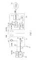
- Fig. 1is a block diagram showing a power cord and plug of a bed having a first near field communication antenna carried by a plug body of the plug, the bed having first near field communication circuitry coupled thereto, and showing a second near field communication antenna and associated second near field communication circuitry included in a module adjacent a wall outlet;
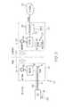
- Fig. 2is a block diagram, similar to Fig. 1 , but having both the first near field communication circuitry and first near field communication antenna carried by the plug body;
- Fig. 3is a block diagram, similar to Fig. 1 , but having an auxiliary power outlet mounted to the bed and additional near field communication antennae and circuitry provided on the bed and on a medical device that receives power from the auxiliary power outlet.
- a power plug 10 at the end of a power cord 12includes a plug body 14 as shown diagrammatically in Fig. 1 .
- Power plug 10is a standard AC power plug in some embodiments. In other embodiments, plug 10 is a DC power plug.
- cord 12extends from a patient support apparatus 16, such as a hospital bed, but the teachings of this disclosure are applicable to all devices that receive power via an AC power plug and that transmit or receive data. Such devices may include computers of all types, home appliances, industrial equipment, laboratory equipment, data acquisition equipment, monitoring equipment, musical equipment, telecommunications devices, audio equipment, and video equipment, just to name a few.
- Plug 10includes prongs 18 that are received in sockets 22 of a standard AC power outlet or receptacle. The words "outlet” and "receptacle” are used interchangeably in this disclosure.
- a first near field communication (NFC) antenna 24is carried by plug body 14 and a second NFC antenna 26 is included in a communication module 28 that is located in proximity to outlet 20.
- module 26is coupled to a computer network 30 with which bed 16 communicates.
- Network 30includes, for example, computer devices such as nurse call computers, electronic medical records (EMR) computers, admission/discharge/transfer (ADT) computers, and the like in those embodiments in which plug 10 and module 26 is used in the healthcare setting with medical devices such as bed 16.
- EMRelectronic medical records
- ADTadmission/discharge/transfer
- first NFC antenna 24is coupled to first near field communication circuitry 32 and second NFC antenna 26 is coupled to second near field communication circuitry 34.
- circuitry 32is carried by bed 16, such as by being mounted to a bed frame of bed 16, and is coupled to antenna 24 via one or more conductors 36 routed along cable 12.
- the power conductors of cable 12i.e., the conductors that couple to prongs 18
- conductors 36are contained within the same cable jacket.
- shieldingis provided so as to reduce or eliminate the AC power from interfering with the data signals transmitted over conductors 36.
- circuitry 32is carried by plug body 14' and is coupled to circuitry of bed 16 via one or more conductors 36' that are routed along cable 12.
- NFC antennae 24, 26 and associated circuitry 32, 34permits simplified transactions, data exchange, and wireless connections between two devices in close proximity to each other, usually by no more than a few centimeters.
- antennae 24, 26are spaced apart by about 1 inch (2.54 cm).
- suitable resultscan be achieved with antennae 24, 26 being spaced apart by 4 cm or less.
- a working distance of up to 20 cmmay be possible, but in the illustrative embodiments, communication over such a distance is not needed.
- NFCnear field communication
- NFCoperates at a frequency of about 13.56 megahertz (MHz) on ISO/IEC 18000-3 air interface and at data transfer rates from about 106 kilobits per second (kbits/s) to about 424 kbits/s.
- circuitry 32 and circuitry 34are both powered such that bidirectional, peer-to-peer communication is achieved.
- one of antenna 24, 26 and the associated circuitry 32, 34, respectively,serves as an initiator circuit and the other of antenna 24, 26 and associated circuitry 32, 34 serves as a passive target.
- the initiatoractively generates a radio frequency (RF) field that powers the passive target.
- the passive targetscan be fashioned as tags, stickers, fobs, or cards that do not include batteries or direct connection to external power sources.
- antenna 24is included in a label that sticks to plug body 14 (or plug body 14') in some embodiments.
- Circuitry 32 and/or circuitry 34are sometimes referred to as read/write modules according to this disclosure.
- the NFC antennae 24, 26automatically establish communications quickly in roughly one tenth of a second after plug 10 is plugged into outlet 20. Because plug 10 is configured to receive power and is configured to communicate wirelessly with module 26, only one connector (i.e., plug 10) is needed to provide both power and data to device 16 and furthermore, only this single connector needs to be unplugged if device 16 is to be moved to a new location. Due to the short reception range between antennae 24, 26, the likelihood of unwanted interference from other wireless signals is reduced.
- the labels, stickers, or tags that carry the antennae 24, 26are approximately the size of a U.S. quarter which has a diameter of 24.26 mm (0.955 in) or roughly 1 inch. Thus, in some embodiments, the labels carrying antenna 24 are simply stuck onto plug body 14, 14'.
- the antenna 24, 26can be placed up to 10 feet away from a transceiver chip of the associated circuitry 32, 34. Thus, in the Fig. 1 example, conductor 36 has a maximum length of about ten feet.
- circuitry 32, 34includes TRF7970A transceiver boards available from Texas Instruments of Dallas, Texas. By placing the circuitry 32 on bed 16 as shown in the Fig.
- plug body 14only has the added weight of antenna 24 and a small portion of the length of conductors 36.
- plug 10has less of a tendency to fall out of socket 20 which is an improvement over the embodiments shown and described in U.S. Patent No. 7,399,205 which is already incorporated herein by reference.
- Circuitry 32may be included in an electronics housing mounted on a frame of bed 16, for example. In other embodiments contemplated by this disclosure, however, circuitry 32 is carried by the plug body 14' as shown in Fig. 2 .
- module 28which carries antenna 26 and associated circuitry 34 can be fashioned in any number of ways, including the various embodiments shown in U.S. Patent No. 7,399,205 .
- module 28may be fashioned as a wall plate that carries antenna 26 and that has an opening through which the sockets 22 of AC power outlet 20 are accessible for receiving prongs 18 of plug 10.
- the wall plate carrying the antenna 26is configured to cover an existing wall plate associated with the AC power outlet 20 in some embodiments.
- Such an embodiment of a wall platemay be fashioned similarly to the embodiment of Figs. 1-4 of U.S. Patent No. 7,399,205 , for example.
- the wall plate or module 26 carrying antenna 26replaces the existing wall plate altogether.
- antenna 26is carried in a housing or plate that mounts to a wall or similar structure in close proximity to outlet 20 but without covering up any of the existing wall plate of the outlet 20.
- close proximityis intended to mean close enough that communications between antenna 26 and antenna 24 is possible when plug 10 is coupled to outlet 20.
- antennais carried in a housing of an adapter module that plugs into outlet 20.
- the adapter modulemay be fashioned similar to any of those shown in Figs. 8-12 of U.S. Patent No. 7,399,205 for example.
- circuitry 34is included in the same module 28 as antenna 26 in some embodiments.
- further processor circuitry 40is also included in module 28.
- circuitry 28 and/or circuitry 40is included in a housing that is separate from the module 28 that carries antenna 26.
- a communication cableinterconnects the module 28 carrying antenna 26 with the housing or module carrying circuitry 28 and/or circuitry 40.
- module 28is not connected to network 30 but rather simply serves to provide the circuitry of bed 16 with a location identifier (ID) that is transmitted from antenna 26 to antenna 24.
- the circuitry of bed 16transmits a bed identifier (ID) and the location identifier such as by wireless communications with a wireless access point, for example.
- the wireless access pointis coupled to the network 30.
- Remote computers of the network 30receive the bed ID and the location ID to associate bed 16 with the location in the healthcare facility at which bed 16 is located.
- bed 16transmits additional data, such as bed status information, patient physiological data, bed diagnostic data, and so forth.
- the bed ID and/or the additional datais transmitted via antenna 24 to antenna 26 and then on to network 30 via circuitry 34 and/or circuitry 40.
- the location ID of module 28is also transmitted so that the bed-to-room association can be made by remote computers in those embodiments as well.
- Bed Type 1is the TOTALCARE® bed
- Bed Type 2is the VERSACARE® bed
- Bed Type 3is the CAREASSIST® ES bed
- Bed Type 4is the ADVANTATM 2 bed
- Bed Type 5is the ADVANCE bed
- Bed Type 6is the ADVANTA bed, each of which is, or was, marketed by Hill-Rom Company, Inc.
- Beds 16 of other types which have other types of bed dataare, of course, usable.
- bed dataincludes, for example, data pertaining to one or more of the following: a position of one portion of a bed frame relative to another portion of the bed frame (e.g., Brake Status, Bed Low Position, Rail positions, Head Angle), a mattress function (e.g., Wound Surface and Pulmonary Surface information), a status of a bed exit alarm system of the hospital bed (e.g., the patient position monitoring (PPM) information), and patient physiologic data (e.g., patient weight).
- maintenance and/or service datais among the type of bed data that is transmitted from bed 16 via near field communication circuitry 32, 34 and antennae 24, 26 to network 30, for various embodiments of bed 16.
- bed 16has a mattress and/or bed frame with sensors to sense patient physiologic data (e.g., heart rate, temperature, respiration rate, blood oxygenation, blood pressure, etc.) and that such data is also among the bed data communicated from bed 16 to circuitry 32 and antenna 24 and then on to network 30 via antenna 26 and circuitry 34.
- patient physiologic datae.g., heart rate, temperature, respiration rate, blood oxygenation, blood pressure, etc.
- patient physiologic datae.g., heart rate, temperature, respiration rate, blood oxygenation, blood pressure, etc.
- bed 16includes an auxiliary power outlet 50 which has sockets 52 that receive prongs 54 of a plug 56 provided at the end of a power cord 58 extending from a medical device 60.
- Medical device 60may comprise any type of medical device used for providing care to a patient or used in monitoring a patient physiological condition, for example.
- examples of some medical devices 60include IV pumps, blood pressure monitors, electrocardiographs (EKG's), electroencephalographs (EEG's), pulse oximeters, ventilators, respiration monitors, and temperature monitors, just to name a few.
- poweris provided to auxiliary outlet 50 from power cord 12.
- isolation circuitryis included in bed 16 so as to isolate bed power from the auxiliary power.
- a separate power cord 62extends from bed 16 and has a plug 64 with prongs 66 that are received in sockets of a power outlet.
- power cord 62is shown diagrammatically via a dotted line and prongs 66 of plug 64 are shown arranged for coupling to sockets 22' of a duplex power outlet 20'.
- power cord 62 and auxiliary outlet 50are not electrically coupled in any way to the circuitry of bed 16, but rather bed 16 serves as a carrier for auxiliary outlet 50.
- Bed 16may have more than one auxiliary outlet 50.
- the discussion below of near field communication capability associated with one auxiliary outlet 50is equally applicable for each auxiliary outlet of a bed having multiple such outlets.
- bed 16has an additional near field communication antenna 124 and additional near field communication circuitry 132 in close proximity to auxiliary outlet 50 as shown diagrammatically in Fig. 3 .
- Antenna 124communicates wirelessly with a further near field communication antenna 126 provided on plug 56.
- antenna 126is included as part of a passive circuit carried by a label coupled to plug 56.
- IDmedical device identification
- bed 16transmits an appropriate alert message to network 30 and, in some embodiments, disconnects power from auxiliary outlet 50 so as to turn off medical device 60.
- bed 16includes a visual indicator of some sort, such as a message on a graphical display screen or an alert light, to indicate locally that an inappropriate device has been connected to auxiliary outlet 50.
- bed 16is configurable such that its one or more auxiliary outlets 50 are designated for specific pieces or equipment or specific types of equipment.
- the near field communication capability of bed 16 associated with the auxiliary outlet(s) 50are used to verify that the designated equipment is coupled to outlet(s) 50.
- bed 16interacts with and/or controls device 60 via data transmitted via antennae 124, 126.
- a touch screen display on bed 16is configured to accept user inputs for controlling device 60 in some embodiments.
- outlets associated with the critical power gridare typically indicated by being red or orange in color and outlets associated with non-critical power grid are typically white or off white in color.
- one or more generatorsare usually operated to provide back-up power to the critical power grid.
- near field communication components 124, 126, 132, 134are used to make sure that only medical devices 60 that are deemed critical (i.e., the appropriate or proper medical devices) are used with the one or more auxiliary outlets 50 of bed 16.
- medical devices 60include near field communication circuitry 134 which is coupled to antenna 126 via conductors 136 as indicated diagrammatically.
- Circuitry 134is used for transmitting medical device data to the circuitry of bed 16 via antennae 126, 124 and circuitry 132.
- bed datais transmitted to medical device 60 via circuitry 132, 134 and antennae 124, 126.
- device 60is an infusion pump or drug delivery pump
- bed 16may transmit patient weight data to device 60 which, in turn, may use the patient weight data to establish a rate at which a fluid or drug is administered to the associated patient.
- circuitry 134is shown as being carried by medical device 60 in Fig. 3 , however, in other embodiments, circuitry 134 is carried by plug 56.
- data communicated to bed 16 from device 60 via near field communication components 124, 126, 132, 134is subsequently transmitted to network via near filed communication components 24, 26, 32, 34.
- near filed communication components 24, 26, 32, 34are omitted and bed transmits data received from device 60 to network 30 via some other wireless communication scheme, such as Wi-Fi communication to a wireless access point, for example, or via a wired connection to network 30.
- bed 16 in each of the Fig. 1-3 examplesis shown as having optional Wi-Fi circuitry 80 and module 28 is shown as having Wi-Fi circuitry 82. Further features of Wi-Fi circuitry 80, 82 are discussed below.
- the near field communication components 24, 26, 32, 34may serve as a secondary or back-up communication channel between bed 16 and remote computer devices of network 30.
- bed 16may couple to network 30 via a separate nurse call cable, such as a 37-pin cable typically used to connect Hill-Rom beds to a nurse call system, which serves as the primary communication channel for data to and from bed 16.
- the primary nurse call channeloperates at faster data transfer rates than the data transfer rate at which near field communication components 24, 26, 32, 34 operate.
- near field communication components 24, 26, 32, 34are used for determining bed-to-room location and then bed uses another communications channel, such as a wired connection or wi-fi to wireless access point communication, as the primary communication channel.
- antenna 24is not mounted on plug 14 but instead, is coupled to some other portion of bed 16.
- antenna 24is mounted on a base frame of bed 16 in some embodiments.
- antenna 26 and its associated circuitry 34need not be placed near any wall outlet.
- the near field communication components 24, 26, 32, 34operate as a bed docking system which is used for establishing bed-to-room association.
- the near filed communication components 24, 32may be included in a module that bolts onto, or otherwise mounts, to bed 16 and then components 26, 34 are wall mounted and wired to network 30. This allows for retrofitting existing beds with near field communication components 26, 34, again, for bed-to-room association purposes.
- wall mountedis intended to encompass mounting onto a room wall or onto a portion of some other piece of architectural equipment (e.g., headwall units, columns, arms, carts, chases, bed locators) found in a patient room, as well as mounting on a floor or ceiling.
- wall outletis intended to cover power outlets mounted to room walls and power outlets mounted on other architectural equipment, a ceiling, or a floor.
- the Wi-Fi circuitry 80, 82is used to support secondary radio communications, such as voice communications or entertainment (e.g., television or radio) audio signal communications, to and from bed 16.
- Wi-Fi circuitry 80, 82operates according to the Bluetooth protocol, although any suitable wireless technology is usable.
- the Wi-Fi circuitry 80, 82uses bed ID and location ID transmitted via antennae 24, 26 to automatically pair up for the secondary radio communications. However, this need not be the case if circuitry 80, 82 is operable to perform the automatic pairing functions themselves.
- a patient on bed 16communicates with a caregiver at a remote nurse's station by pressing a nurse call button or switch as is known in the art.
- the patient's voiceis picked up by a microphone on bed 16 and transmitted to the remote nurse's station via circuitry 80, 82 and the caregiver's voice is heard by the patient through a speaker on bed 16 that receives the caregiver's voice audio via circuitry 80, 82.
- circuitry and componentssuch as network 30 and processor 40 are included in the audio data link between the bed 16 and remote nurse's station in some embodiments.
- bed 16configures itself differently based on location ID data transmitted via antenna 26 from module 28 and received by antenna 24. For example, if the location ID indicates that the bed 16 is located in a med/surg room (e.g., a typical patient room) the bed 16 configures its settings in one way and if the location ID indicates that the bed is located in the intensive care unit (ICU), the bed 16 configures its setting in another way. Some screens that are shown on the graphical user interface of bed 16 for control of various features of bed 16 may be enabled or disabled depending upon the location of bed 16. Further according to this disclosure, patient ID data is transmitted from a remote computer of network 30 to bed 16 via antennae 24, 26 and bed 16 configures itself based on patient ID.
- ICUintensive care unit
- CRTcontinuous lateral rotation therapy
- alternating pressure therapylow air loss therapy
- low air loss therapylow air loss therapy
- bed 16will enable the appropriate therapy based on the patient ID.
- the location IDis used by the bed 16 to configure room lighting or to determine the type of television in the room and so forth. It is further contemplated that in some embodiments, the location ID is used by bed 16 to enable features such as permitting a patient to order and pay for video on demand or to turn on features of a rental bed or to gain access to remote servers or websites for looking up medical information. Data communicated between antenna 24 of bed 16 and antenna 26 of module 28 is used, in some embodiments, to synchronize display of data from devices 60 on a display of bed 16, or vice versa, and even to provide display information to mobile devices carried by caregivers.
Landscapes
- Engineering & Computer Science (AREA)
- Health & Medical Sciences (AREA)
- Life Sciences & Earth Sciences (AREA)
- Computer Networks & Wireless Communication (AREA)
- Signal Processing (AREA)
- Biomedical Technology (AREA)
- Physics & Mathematics (AREA)
- Public Health (AREA)
- General Health & Medical Sciences (AREA)
- Medical Informatics (AREA)
- Surgery (AREA)
- Molecular Biology (AREA)
- Veterinary Medicine (AREA)
- Animal Behavior & Ethology (AREA)
- Biophysics (AREA)
- Pathology (AREA)
- Heart & Thoracic Surgery (AREA)
- Business, Economics & Management (AREA)
- Emergency Management (AREA)
- General Physics & Mathematics (AREA)
- Primary Health Care (AREA)
- General Business, Economics & Management (AREA)
- Epidemiology (AREA)
- Measuring And Recording Apparatus For Diagnosis (AREA)
- Accommodation For Nursing Or Treatment Tables (AREA)
Abstract
Description
- The present disclosure relates to connectors having wired and wireless couplings. The present disclosure also relates to apparatus for associating a hospital bed to a location in a healthcare facility or for transferring data between a hospital bed and a network of computer devices in a healthcare facility, but has use in other applications and in other environments as well.
- Wireless communication between patient-support devices, such as hospital beds, and a network of a healthcare facility are known. For example,
U.S. Patent No. 7,399,205 , which is hereby incorporated by reference herein, discloses the use of wireless communication circuitry in a plug body of a standard AC power plug and a module that is mounted in a room adjacent a standard AC power receptacle or outlet. Having circuitry included in the plug body increases the weight of the plug body and introduces plug retention issues. That is, the added weight of the circuitry in the plug body has a tendency to cause the plug to fall out of the receptacle. Also, in those embodiments of the '205 patent relying on the use of photodiodes for data transfer, the necessary alignment tolerance requirements present issues of their own. Accordingly, there is a need to improve upon the devices of the '205 patent. - The present invention may comprise one or more of the following features, alone or in any combination.
- An apparatus may be provided for providing data communication and power to a device located in a room having a power outlet. The apparatus may include a cable that may extend from the device and that may have at one end thereof a plug which may have a plug body. A plurality of prongs may extend from the plug body and may be configured to couple to the power outlet to receive power. The apparatus may further include a first near field communication antenna which may be carried by the plug body. A communication module may be provided and may comprise a second near field communication antenna. The communication module may be located in the room in proximity to the plug. At least one of the first near field communication antenna and the second near field communication antenna may communicate data wirelessly to the other of the first near field communication antenna and the second near field communication antenna.
- According to this disclosure, near field communication circuitry may be carried by the device and may be coupled to the first near field communication antenna via at least one conductor that may be routed along the cable. In some embodiments, near field communication circuitry may be carried by the plug body and may be coupled to the first near field communication antenna. The power outlet may comprise, for example, a standard AC power outlet. A DC power outlet is contemplated as an alternative.
- In some embodiments, the first near field communication antenna and the second near field communication antenna may be spaced apart by about four centimeters (4 cm) or less when the first near field communication antenna and the second near field communication antenna communicate wirelessly. It is possible, however, for the first and second near field communication antennae to be spaced apart by a greater distance, such as up to 3 inches (7.62 cm) apart, as long as the first and second near field communication antennae are able to successfully receive wireless signals from each other. According to this disclosure, the first near field communication antenna may optionally be included in a label that may stick to the plug body.
- In some embodiments, the first near field communication antenna may serve as a passive target and the second near field communication antenna may be coupled to initiator circuitry that may actively generate a radio frequency field via the second near field communication antenna to power up the passive target for data transfer. Alternatively or additionally, the second near field communication antenna may serve as a passive target and the first near field communication antenna may be coupled to initiator circuitry that actively generates a radio frequency field via the first near field communication antenna to power up the passive target for data transfer.
- In some embodiments, a wall plate may carry the second near field communication antenna. The wall plate may have an opening through which the power outlet may be accessible. The wall plate carrying the second near field communication antenna may be configured to cover an existing wall plate associated with the power outlet.
- According to this disclosure, first circuitry may be coupled to the first near field communication antenna and second circuitry may be coupled to the second near field communication antenna. The first and second circuitry may communicate via the first near field communication antenna and the second near field communication antenna according to a peer-to-peer protocol. In some embodiments, a read/write module may be carried by the plug body and coupled to the first near field communication antenna. Alternatively or additionally, a read/write module may be coupled to the second near field communication antenna.
- According to an aspect of this disclosure, an apparatus for coupling a patient-support device to a power outlet and to a computer network in a healthcare facility may be provided. The apparatus may comprise a cable that may extend from the patient-support device and that may have at one end thereof a plug which may comprise a plug body. A plurality of prongs may extend from the plug body and may be configured to couple to the power outlet to receive power. A first near field communication antenna may be carried by the plug body. The apparatus may also have a communication module that may include a second near field communication antenna. At least one of the first near field communication antenna and the second near field communication antenna may communicate data wirelessly to the other of the first near field communication antenna and the second near field communication antenna.
- In some embodiments, the communication module may include a housing that may be in close proximity to the power outlet. The second near field communication antenna may be situated in the housing. Optionally, the housing may have an opening through which the plug may be inserted to couple to the power outlet. According to this disclosure, the communication module may comprise a mounting plate that may mount over a cover plate associated with the power outlet. The housing may, in turn, couple to the mounting plate. In some embodiments, the communication module may comprise a Nurse Call cancel button.
- According to this disclosure, near field communication circuitry may be carried by the patient-support device and may be coupled to the first near field communication antenna via at least one conductor that may be routed along the cable. In some embodiments, the near field communication circuitry may be carried by the plug body and may be coupled to the first near field communication antenna. According to this disclosure, the first near field communication antenna optionally may be included in a label that may stick to the plug body.
- According to an aspect of this disclosure, a system may include a bed having an auxiliary power outlet and a medical device that may include a cable which may have at one end thereof a plug comprising a plug body. A plurality of prongs may extend from the plug body and may couple to the auxiliary power outlet to receive power. The system may have a first near field communication antenna carried by the plug body and a communication module which may have a second near field communication antenna. The communication module may be coupled to the bed in proximity to the auxiliary power outlet. At least one of the first near field communication antenna and the second near field communication antenna may communicate data wirelessly to the other of the first near field communication antenna and the second near field communication antenna.
- In some embodiments, the bed may receive data from the medical device via the first and second near field communication antennae. The bed may be configured to send at least some of the data received from the medical device to a unit spaced from the bed. For example, the bed may have a third near field communication antenna and the unit spaced from the bed may have a fourth near field communication antenna. The data sent by the bed may be transmitted from the third near field communication antenna to the fourth near field communication antenna.
- According to a further aspect of this disclosure, a system may include a patient support apparatus, a first near field communication module that may be coupled to the patient support apparatus, and a second near field communication module that may be spaced from the patient support apparatus. The first near field communication module may have a first near field communication antenna and the second near field communication module may have a second near field communication antenna. At least one of the first near field communication antenna and the second near field communication antenna may communicate data wirelessly to the other of the first near field communication antenna and the second near field communication antenna. In some embodiments, the first near field communication module retrofits onto the patient support apparatus and the second near field communication module attaches to a surface associated with a room in which the patient support apparatus is located.
- The invention will now be further described by way of example with reference to the accompanying drawings, in which:
Fig. 1 is a block diagram showing a power cord and plug of a bed having a first near field communication antenna carried by a plug body of the plug, the bed having first near field communication circuitry coupled thereto, and showing a second near field communication antenna and associated second near field communication circuitry included in a module adjacent a wall outlet;Fig. 2 is a block diagram, similar toFig. 1 , but having both the first near field communication circuitry and first near field communication antenna carried by the plug body; andFig. 3 is a block diagram, similar toFig. 1 , but having an auxiliary power outlet mounted to the bed and additional near field communication antennae and circuitry provided on the bed and on a medical device that receives power from the auxiliary power outlet.- A
power plug 10 at the end of apower cord 12 includes aplug body 14 as shown diagrammatically inFig. 1 .Power plug 10 is a standard AC power plug in some embodiments. In other embodiments, plug 10 is a DC power plug. In the illustrative example,cord 12 extends from apatient support apparatus 16, such as a hospital bed, but the teachings of this disclosure are applicable to all devices that receive power via an AC power plug and that transmit or receive data. Such devices may include computers of all types, home appliances, industrial equipment, laboratory equipment, data acquisition equipment, monitoring equipment, musical equipment, telecommunications devices, audio equipment, and video equipment, just to name a few.Plug 10 includesprongs 18 that are received insockets 22 of a standard AC power outlet or receptacle. The words "outlet" and "receptacle" are used interchangeably in this disclosure. - According to this disclosure, a first near field communication (NFC)
antenna 24 is carried byplug body 14 and asecond NFC antenna 26 is included in acommunication module 28 that is located in proximity tooutlet 20. In the illustrative examples ofFigs. 1 and2 ,module 26 is coupled to acomputer network 30 with whichbed 16 communicates.Network 30 includes, for example, computer devices such as nurse call computers, electronic medical records (EMR) computers, admission/discharge/transfer (ADT) computers, and the like in those embodiments in which plug 10 andmodule 26 is used in the healthcare setting with medical devices such asbed 16. Examples of the type of communication equipment included in various embodiments of a nurse call system (as well asnetwork 30, in general) can be found inU.S. Patent Nos. 7,746,218 ;7,538,659 ;7,319,386 ;7,242,308 ;6,897,780 ;6,362,725 ;6,147,592 ;5,838,223 ;5,699,038 and5,561,412 andU.S. Patent Application Publication Nos. 2009/0217080 ;2009/0214009 ;2009/0212956 ; and2009/0212925 . - In the illustrative examples of
Figs. 1 and2 ,first NFC antenna 24 is coupled to first nearfield communication circuitry 32 andsecond NFC antenna 26 is coupled to second nearfield communication circuitry 34. In theFig. 1 embodiment,circuitry 32 is carried bybed 16, such as by being mounted to a bed frame ofbed 16, and is coupled toantenna 24 via one ormore conductors 36 routed alongcable 12. In some embodiments, the power conductors of cable 12 (i.e., the conductors that couple to prongs 18) andconductors 36 are contained within the same cable jacket. Optionally, shielding is provided so as to reduce or eliminate the AC power from interfering with the data signals transmitted overconductors 36. In theFig. 2 embodiment,circuitry 32 is carried by plug body 14' and is coupled to circuitry ofbed 16 via one or more conductors 36' that are routed alongcable 12. - Use of
NFC antennae circuitry Figs. 1 and2 ,antennae antennae circuitry antennae - In the illustrative example,
circuitry 32 andcircuitry 34 are both powered such that bidirectional, peer-to-peer communication is achieved. In other embodiments, one ofantenna circuitry antenna circuitry antenna 24 is included in a label that sticks to plug body 14 (or plug body 14') in some embodiments.Circuitry 32 and/orcircuitry 34 are sometimes referred to as read/write modules according to this disclosure. - By having
NFC antenna 24 included on plug body 14 (or plug body 14') and by havingmodule 28 located in close proximity tooutlet 20, theNFC antennae plug 10 is plugged intooutlet 20. Becauseplug 10 is configured to receive power and is configured to communicate wirelessly withmodule 26, only one connector (i.e., plug 10) is needed to provide both power and data todevice 16 and furthermore, only this single connector needs to be unplugged ifdevice 16 is to be moved to a new location. Due to the short reception range betweenantennae - The labels, stickers, or tags that carry the
antennae labels carrying antenna 24 are simply stuck ontoplug body 14, 14'. Theantenna circuitry Fig. 1 example,conductor 36 has a maximum length of about ten feet. In some embodiments,circuitry circuitry 32 onbed 16 as shown in theFig. 1 embodiment, plugbody 14 only has the added weight ofantenna 24 and a small portion of the length ofconductors 36. Thus, plug 10 has less of a tendency to fall out ofsocket 20 which is an improvement over the embodiments shown and described inU.S. Patent No. 7,399,205 which is already incorporated herein by reference.Circuitry 32 may be included in an electronics housing mounted on a frame ofbed 16, for example. In other embodiments contemplated by this disclosure, however,circuitry 32 is carried by the plug body 14' as shown inFig. 2 . - The
module 28 which carriesantenna 26 and associatedcircuitry 34 can be fashioned in any number of ways, including the various embodiments shown inU.S. Patent No. 7,399,205 . For example,module 28 may be fashioned as a wall plate that carriesantenna 26 and that has an opening through which thesockets 22 ofAC power outlet 20 are accessible for receivingprongs 18 ofplug 10. The wall plate carrying theantenna 26 is configured to cover an existing wall plate associated with theAC power outlet 20 in some embodiments. Such an embodiment of a wall plate may be fashioned similarly to the embodiment ofFigs. 1-4 ofU.S. Patent No. 7,399,205 , for example. - In other embodiments, the wall plate or
module 26 carryingantenna 26 replaces the existing wall plate altogether. In further embodiments,antenna 26 is carried in a housing or plate that mounts to a wall or similar structure in close proximity tooutlet 20 but without covering up any of the existing wall plate of theoutlet 20. The term "close proximity" is intended to mean close enough that communications betweenantenna 26 andantenna 24 is possible whenplug 10 is coupled tooutlet 20. In still other embodiments, antenna is carried in a housing of an adapter module that plugs intooutlet 20. The adapter module may be fashioned similar to any of those shown in Figs. 8-12 ofU.S. Patent No. 7,399,205 for example. - As shown diagrammatically in
Figs. 1 and2 , this disclosure contemplates thatcircuitry 34 is included in thesame module 28 asantenna 26 in some embodiments. In some embodiments, such as the illustrative embodiments,further processor circuitry 40 is also included inmodule 28. In other embodiments,circuitry 28 and/orcircuitry 40 is included in a housing that is separate from themodule 28 that carriesantenna 26. In such embodiments, a communication cable interconnects themodule 28 carryingantenna 26 with the housing ormodule carrying circuitry 28 and/orcircuitry 40. - In some embodiments,
module 28 is not connected to network 30 but rather simply serves to provide the circuitry ofbed 16 with a location identifier (ID) that is transmitted fromantenna 26 toantenna 24. The circuitry ofbed 16, in turn, transmits a bed identifier (ID) and the location identifier such as by wireless communications with a wireless access point, for example. In such an embodiment, the wireless access point is coupled to thenetwork 30. Remote computers of thenetwork 30 receive the bed ID and the location ID toassociate bed 16 with the location in the healthcare facility at whichbed 16 is located. In some embodiments,bed 16 transmits additional data, such as bed status information, patient physiological data, bed diagnostic data, and so forth. In other embodiments, the bed ID and/or the additional data is transmitted viaantenna 24 toantenna 26 and then on tonetwork 30 viacircuitry 34 and/orcircuitry 40. The location ID ofmodule 28 is also transmitted so that the bed-to-room association can be made by remote computers in those embodiments as well. - Examples of the type of bed data that is transmitted from
bed 16 via nearfield communication circuitry antennae network 30, for various embodiments ofbed 16, is summarized below in Table 1 as follows:


- In the example of Table 1,
Bed Type 1 is the TOTALCARE® bed,Bed Type 2 is the VERSACARE® bed, Bed Type 3 is the CAREASSIST® ES bed, Bed Type 4 is theADVANTA™ 2 bed, Bed Type 5 is the ADVANCE bed, and Bed Type 6 is the ADVANTA bed, each of which is, or was, marketed by Hill-Rom Company, Inc.Beds 16 of other types which have other types of bed data are, of course, usable. Based on Table 1, it will be appreciated that bed data includes, for example, data pertaining to one or more of the following: a position of one portion of a bed frame relative to another portion of the bed frame (e.g., Brake Status, Bed Low Position, Rail positions, Head Angle), a mattress function (e.g., Wound Surface and Pulmonary Surface information), a status of a bed exit alarm system of the hospital bed (e.g., the patient position monitoring (PPM) information), and patient physiologic data (e.g., patient weight). It is also contemplated by this disclosure that maintenance and/or service data is among the type of bed data that is transmitted frombed 16 via nearfield communication circuitry antennae network 30, for various embodiments ofbed 16. - In some contemplated embodiments,
bed 16 has a mattress and/or bed frame with sensors to sense patient physiologic data (e.g., heart rate, temperature, respiration rate, blood oxygenation, blood pressure, etc.) and that such data is also among the bed data communicated frombed 16 tocircuitry 32 andantenna 24 and then on tonetwork 30 viaantenna 26 andcircuitry 34. An example of a mattress with physiologic sensors can be found inU.S. Patent Nos. 7,515,059 ;7,330,127 and6,721,980 . Other examples of mattresses and bed frames having physiologic sensors can be found inU.S. Patent Application Publication No. 2010/0101022 . - Referring now to
Fig. 3 , an embodiment is shown in whichbed 16 includes anauxiliary power outlet 50 which hassockets 52 that receiveprongs 54 of aplug 56 provided at the end of apower cord 58 extending from amedical device 60.Medical device 60 may comprise any type of medical device used for providing care to a patient or used in monitoring a patient physiological condition, for example. Thus, examples of somemedical devices 60 include IV pumps, blood pressure monitors, electrocardiographs (EKG's), electroencephalographs (EEG's), pulse oximeters, ventilators, respiration monitors, and temperature monitors, just to name a few. - In some embodiments, power is provided to
auxiliary outlet 50 frompower cord 12. In such embodiments, isolation circuitry is included inbed 16 so as to isolate bed power from the auxiliary power. In other embodiments, aseparate power cord 62 extends frombed 16 and has a plug 64 withprongs 66 that are received in sockets of a power outlet. In the illustrative example ofFig. 3 ,power cord 62 is shown diagrammatically via a dotted line and prongs 66 of plug 64 are shown arranged for coupling to sockets 22' of a duplex power outlet 20'. Thus, in this alternative embodiment,power cord 62 andauxiliary outlet 50 are not electrically coupled in any way to the circuitry ofbed 16, but ratherbed 16 serves as a carrier forauxiliary outlet 50.Bed 16 may have more than oneauxiliary outlet 50. Thus, the discussion below of near field communication capability associated with oneauxiliary outlet 50 is equally applicable for each auxiliary outlet of a bed having multiple such outlets. - According to this disclosure,
bed 16 has an additional nearfield communication antenna 124 and additional nearfield communication circuitry 132 in close proximity toauxiliary outlet 50 as shown diagrammatically inFig. 3 .Antenna 124 communicates wirelessly with a further nearfield communication antenna 126 provided onplug 56. In some embodiments,antenna 126 is included as part of a passive circuit carried by a label coupled to plug 56. In such embodiments, after the passive circuitry has been activated bycircuitry 132 ofbed 16 viaantenna 124, medical device identification (ID) data is transmitted viaantenna 126 toantenna 124 to confirm that a proper device has been plugged into theauxiliary outlet 50. - If it is determined by circuitry of
bed 16 that an inappropriate or wrong device has been plugged intooutlet 50, thenbed 16 transmits an appropriate alert message to network 30 and, in some embodiments, disconnects power fromauxiliary outlet 50 so as to turn offmedical device 60. In some embodiments,bed 16 includes a visual indicator of some sort, such as a message on a graphical display screen or an alert light, to indicate locally that an inappropriate device has been connected toauxiliary outlet 50. Thus, according to this disclosure,bed 16 is configurable such that its one or moreauxiliary outlets 50 are designated for specific pieces or equipment or specific types of equipment. The near field communication capability ofbed 16 associated with the auxiliary outlet(s) 50 are used to verify that the designated equipment is coupled to outlet(s) 50. In some embodiments,bed 16 interacts with and/orcontrols device 60 via data transmitted viaantennae bed 16 is configured to accept user inputs for controllingdevice 60 in some embodiments. - In many hospitals and other types of healthcare facilities, there are two separate power grids, one being a critical power grid and the other being a non-critical power grid. Outlets associated with the critical power grid are typically indicated by being red or orange in color and outlets associated with non-critical power grid are typically white or off white in color. During a power outage or other emergency in which power to a hospital or healthcare facility is lost, one or more generators are usually operated to provide back-up power to the critical power grid.
It is desirable, therefore, that only critical devices, such as ventilators, infusion pumps, and other devices that provide critical care (e.g., life sustaining care) to a patient are connected to outlets associated with the critical power grid so that noncritical devices do not need to be powered by the back-up generators during an emergency or power outage. Thus, according to this disclosure, nearfield communication components medical devices 60 that are deemed critical (i.e., the appropriate or proper medical devices) are used with the one or moreauxiliary outlets 50 ofbed 16. - In some embodiments,
medical devices 60 include nearfield communication circuitry 134 which is coupled toantenna 126 viaconductors 136 as indicated diagrammatically.Circuitry 134 is used for transmitting medical device data to the circuitry ofbed 16 viaantennae circuitry 132. Alternatively or additionally, bed data is transmitted tomedical device 60 viacircuitry antennae device 60 is an infusion pump or drug delivery pump, thenbed 16 may transmit patient weight data todevice 60 which, in turn, may use the patient weight data to establish a rate at which a fluid or drug is administered to the associated patient. As another example, ifdevice 60 senses that its fluid level is running low, then that information may be communicated tobed 16 which, in turn, transmits an alert message to a remote computer device ofnetwork 30, including transmission to a portable wireless communication device carried by a caregiver. Alternatively or additionally, a local alert regarding the alert condition ofdevice 60 is displayed locally onbed 16, such as being displayed on a display screen.Circuitry 134 is shown as being carried bymedical device 60 inFig. 3 , however, in other embodiments,circuitry 134 is carried byplug 56. - In the illustrative example of
Fig. 3 , data communicated tobed 16 fromdevice 60 via nearfield communication components communication components communication components device 60 to network 30 via some other wireless communication scheme, such as Wi-Fi communication to a wireless access point, for example, or via a wired connection tonetwork 30. Thus,bed 16 in each of theFig. 1-3 examples is shown as having optional Wi-Fi circuitry 80 andmodule 28 is shown as having Wi-Fi circuitry 82. Further features of Wi-Fi circuitry - According to one feature, the near
field communication components bed 16 and remote computer devices ofnetwork 30. Thus,bed 16 may couple to network 30 via a separate nurse call cable, such as a 37-pin cable typically used to connect Hill-Rom beds to a nurse call system, which serves as the primary communication channel for data to and frombed 16. In such embodiments, the primary nurse call channel operates at faster data transfer rates than the data transfer rate at which nearfield communication components field communication components - According to another embodiment,
antenna 24 is not mounted onplug 14 but instead, is coupled to some other portion ofbed 16. For example,antenna 24 is mounted on a base frame ofbed 16 in some embodiments. In such embodiments,antenna 26 and its associatedcircuitry 34 need not be placed near any wall outlet. In this embodiment, the nearfield communication components communication components bed 16 and thencomponents network 30. This allows for retrofitting existing beds with nearfield communication components - According to another feature, the Wi-
Fi circuitry bed 16. In some embodiments, Wi-Fi circuitry Fi circuitry antennae circuitry bed 16 communicates with a caregiver at a remote nurse's station by pressing a nurse call button or switch as is known in the art. The patient's voice is picked up by a microphone onbed 16 and transmitted to the remote nurse's station viacircuitry bed 16 that receives the caregiver's voice audio viacircuitry network 30 andprocessor 40 are included in the audio data link between thebed 16 and remote nurse's station in some embodiments. - Also according to this disclosure,
bed 16 configures itself differently based on location ID data transmitted viaantenna 26 frommodule 28 and received byantenna 24. For example, if the location ID indicates that thebed 16 is located in a med/surg room (e.g., a typical patient room) thebed 16 configures its settings in one way and if the location ID indicates that the bed is located in the intensive care unit (ICU), thebed 16 configures its setting in another way. Some screens that are shown on the graphical user interface ofbed 16 for control of various features ofbed 16 may be enabled or disabled depending upon the location ofbed 16. Further according to this disclosure, patient ID data is transmitted from a remote computer ofnetwork 30 tobed 16 viaantennae bed 16 configures itself based on patient ID. For example, certain therapies such as continuous lateral rotation therapy (CLRT), alternating pressure therapy, low air loss therapy, and the like may be indicated for the particular patient andbed 16 will enable the appropriate therapy based on the patient ID. Therapies that may be contraindicated, such as, CLRT for a spinal surgery patient, are disabled bybed 16 based on patient ID. - In some embodiments, the location ID is used by the
bed 16 to configure room lighting or to determine the type of television in the room and so forth. It is further contemplated that in some embodiments, the location ID is used bybed 16 to enable features such as permitting a patient to order and pay for video on demand or to turn on features of a rental bed or to gain access to remote servers or websites for looking up medical information. Data communicated betweenantenna 24 ofbed 16 andantenna 26 ofmodule 28 is used, in some embodiments, to synchronize display of data fromdevices 60 on a display ofbed 16, or vice versa, and even to provide display information to mobile devices carried by caregivers. - Although certain illustrative embodiments have been described in detail above, many embodiments, variations and modifications are possible.


Claims (19)
- An apparatus for providing data communication and power to a device located in a room having a power outlet, the apparatus comprising
a cable extending from the device and having at one end thereof a plug comprising a plug body, a plurality of prongs extending from the plug body and configured to couple to the power outlet to receive power,
a first near field communication antenna carried by the plug body, and
a communication module comprising a second near field communication antenna, the communication module being located in the room in proximity to the plug, at least one of the first near field communication antenna and the second near field communication antenna communicating data wirelessly to the other of the first near field communication antenna and the second near field communication antenna. - The apparatus of claim 1, further comprising a wall plate carrying the second near field communication antenna, the wall plate having an opening through which the AC power outlet is accessible and/or the wall plate being configured to cover an existing wall plate associated with the power outlet.
- An apparatus for coupling a patient-support device to a power outlet and to a computer network in a healthcare facility, the apparatus comprising
a cable extending from the patient-support device and having at one end thereof a plug comprising a plug body, a plurality of prongs extending from the plug body and configured to couple to the power outlet to receive power, and a first near field communication antenna carried by the plug body,
a communication module comprising a second near field communication antenna, at least one of the first near field communication antenna and the second near field communication antenna communicating data wirelessly to the other of the first near field communication antenna and the second near field communication antenna. - An apparatus comprising
a bed having an auxiliary power outlet,
a medical device including a cable having at one end thereof a plug comprising a plug body, a plurality of prongs extending from the plug body and configured to couple to the auxiliary power outlet to receive power,
a first near field communication antenna carried by the plug body, and
a communication module comprising a second near field communication antenna, the communication module being coupled to the bed in proximity to the auxiliary power outlet, at least one of the first near field communication antenna and the second near field communication antenna communicating data wirelessly to the other of the first near field communication antenna and the second near field communication antenna. - The apparatus of claim 4, wherein the bed receives data from the medical device via the first and second near field communication antennae.
- The apparatus of claim 5, wherein the bed is configured to send at least some of the data received from the medical device to a unit spaced from the bed.
- The apparatus of claim 6, wherein the bed has a third near field communication antenna and the unit spaced from the bed has a fourth near field communication antenna, the at least some of the data sent by the bed is transmitted from the third near field communication antenna to the fourth near field communication antenna.
- The apparatus of any preceding claim, further comprising near field communication circuitry carried by the device and coupled to the first near field communication antenna via at least one conductor routed along the cable.
- The apparatus of any preceding claim, further comprising near field communication circuitry carried by the plug body and coupled to the first near field communication antenna.
- The apparatus of any preceding claim, wherein the first near field communication antenna and the second near field communication antenna are spaced apart by about four centimeters (4 cm) or less when the first near field communication antenna and the second near field communication antenna communicate wirelessly.
- The apparatus of any preceding claim, wherein the first near field communication antenna is included in a label that sticks to the plug body.
- The apparatus of any preceding claim, wherein one of the first and second near field communication antennas serves as a passive target and the other near field communication antenna is coupled to initiator circuitry that actively generates a radio frequency field via the said one near field communication antenna to power up the passive target for data transfer.
- The apparatus of any preceding claim, further comprising first circuitry coupled to the first near field communication antenna and second circuitry coupled to the second near field communication antenna, the first and second circuitry communicating via the first near field communication antenna and the second near field communication antenna according to a peer-to-peer protocol.
- The apparatus of any preceding claim, further comprising a read/write module carried by the plug body and coupled to the first near field communication antenna.
- The apparatus of any preceding claim, further comprising a read/write module coupled to the second near field communication antenna.
- The apparatus of any preceding claim, wherein the communication module comprises a housing in close proximity to the power outlet and the second near field communication antenna is situated in the housing.
- The apparatus of claim 16, wherein the housing has an opening through which the plug is inserted to couple to the power outlet.
- The apparatus of either claim 16 or claim 17, wherein the communication module further comprises a mounting plate that mounts over a cover plate associated with the power outlet and the housing couples to the mounting plate.
- The apparatus of any preceding claim, wherein the communication module comprises a Nurse Call cancel button.
Priority Applications (1)
| Application Number | Priority Date | Filing Date | Title |
|---|---|---|---|
| EP17192060.6AEP3280004B1 (en) | 2011-11-29 | 2012-11-29 | Hospital bed having near field communication capability |
Applications Claiming Priority (1)
| Application Number | Priority Date | Filing Date | Title |
|---|---|---|---|
| US201161564466P | 2011-11-29 | 2011-11-29 |
Related Child Applications (1)
| Application Number | Title | Priority Date | Filing Date |
|---|---|---|---|
| EP17192060.6ADivisionEP3280004B1 (en) | 2011-11-29 | 2012-11-29 | Hospital bed having near field communication capability |
Publications (2)
| Publication Number | Publication Date |
|---|---|
| EP2599435A1true EP2599435A1 (en) | 2013-06-05 |
| EP2599435B1 EP2599435B1 (en) | 2017-09-27 |
Family
ID=47429561
Family Applications (2)
| Application Number | Title | Priority Date | Filing Date |
|---|---|---|---|
| EP12194875.6AActiveEP2599435B1 (en) | 2011-11-29 | 2012-11-29 | Hospital bed having near field communication capability |
| EP17192060.6AActiveEP3280004B1 (en) | 2011-11-29 | 2012-11-29 | Hospital bed having near field communication capability |
Family Applications After (1)
| Application Number | Title | Priority Date | Filing Date |
|---|---|---|---|
| EP17192060.6AActiveEP3280004B1 (en) | 2011-11-29 | 2012-11-29 | Hospital bed having near field communication capability |
Country Status (2)
| Country | Link |
|---|---|
| US (2) | US9466877B2 (en) |
| EP (2) | EP2599435B1 (en) |
Cited By (3)
| Publication number | Priority date | Publication date | Assignee | Title |
|---|---|---|---|---|
| WO2016192695A1 (en) | 2015-06-02 | 2016-12-08 | Linet Spol. S.R.O. | Device and method for detecting the presence of bed |
| US9539155B2 (en) | 2012-10-26 | 2017-01-10 | Hill-Rom Services, Inc. | Control system for patient support apparatus |
| EP3861927A1 (en)* | 2020-02-07 | 2021-08-11 | Hill-Rom Services, Inc. | Identification of device location in healthcare facility |
Families Citing this family (27)
| Publication number | Priority date | Publication date | Assignee | Title |
|---|---|---|---|---|
| US9466877B2 (en) | 2011-11-29 | 2016-10-11 | Hill-Rom Services, Inc. | Hospital bed having near field communication capability |
| US9966997B2 (en)* | 2012-09-17 | 2018-05-08 | Stryker Corporation | Communication systems for patient support apparatuses |
| US9478126B2 (en)* | 2013-01-24 | 2016-10-25 | L&P Property Management Company | Remote and controller synchronization for automated furniture controls |
| US9830424B2 (en) | 2013-09-18 | 2017-11-28 | Hill-Rom Services, Inc. | Bed/room/patient association systems and methods |
| US9558641B2 (en)* | 2013-12-18 | 2017-01-31 | J. Brasch Co. | System and method for monitoring a person |
| US20150379441A1 (en)* | 2014-06-30 | 2015-12-31 | Ebay Inc. | Shared asset management system |
| US10085905B2 (en)* | 2014-08-11 | 2018-10-02 | Stryker Corporation | Patient support apparatuses with wireless headwall communication |
| US10410742B2 (en)* | 2014-10-20 | 2019-09-10 | Rational Surgical Solutions, Llc | Method and system for informed consent |
| US9711029B2 (en) | 2014-10-31 | 2017-07-18 | Hill-Rom Services, Inc. | Equipment, dressing and garment wireless connectivity to a patient bed |
| US9999375B2 (en)* | 2015-04-09 | 2018-06-19 | Stryker Corporation | Location detection systems and methods |
| US10395769B2 (en)* | 2015-12-16 | 2019-08-27 | Hill-Rom Services, Inc. | Patient care devices with local indication of correspondence and power line interconnectivity |
| US10489661B1 (en) | 2016-03-08 | 2019-11-26 | Ocuvera LLC | Medical environment monitoring system |
| CN106025729A (en)* | 2016-08-05 | 2016-10-12 | 深圳市岸基科技有限公司 | Intelligent induction socket adopting wireless control |
| US9882610B1 (en)* | 2016-11-08 | 2018-01-30 | Welch Allyn, Inc. | Near field communication sensor system |
| US10600204B1 (en) | 2016-12-28 | 2020-03-24 | Ocuvera | Medical environment bedsore detection and prevention system |
| US10757228B1 (en) | 2017-02-28 | 2020-08-25 | Stryker Corporation | Patient care devices with on-board network communication |
| CN109309510A (en)* | 2017-07-28 | 2019-02-05 | 胜德国际研发股份有限公司 | Wireless transmission assembly and household appliance system |
| TWI652873B (en)* | 2017-07-28 | 2019-03-01 | 勝德國際研發股份有限公司 | Wireless transmission assembly and household appliance system |
| US10456309B2 (en)* | 2017-08-09 | 2019-10-29 | Stryker Corporation | Field configurable patient support apparatuses |
| CN110250774B (en)* | 2018-04-08 | 2021-03-02 | 吉林工程技术师范学院 | Intelligent university student apartment furniture system capable of realizing health data monitoring |
| US11013418B2 (en) | 2018-11-01 | 2021-05-25 | Hill-Rom Services, Inc. | Identification of device location in healthcare facility |
| US10958311B2 (en)* | 2018-11-01 | 2021-03-23 | Hill-Rom Services, Inc. | Identification of device location in healthcare facility |
| US11071454B2 (en) | 2018-12-28 | 2021-07-27 | Hill-Rom Services, Inc. | Identification of device location in healthcare facility |
| US11113935B2 (en)* | 2019-04-15 | 2021-09-07 | Stryker Corporation | Patient support apparatuses with nurse call audio management |
| US12042451B2 (en) | 2020-08-21 | 2024-07-23 | Hill-Rom Services, Inc. | Cable-free bed with wireless pillow speaker |
| US12279999B2 (en) | 2021-01-22 | 2025-04-22 | Hill-Rom Services, Inc. | Wireless configuration and authorization of a wall unit that pairs with a medical device |
| US12186241B2 (en) | 2021-01-22 | 2025-01-07 | Hill-Rom Services, Inc. | Time-based wireless pairing between a medical device and a wall unit |
Citations (11)
| Publication number | Priority date | Publication date | Assignee | Title |
|---|---|---|---|---|
| US5398149A (en)* | 1993-04-23 | 1995-03-14 | Hill-Rom Company, Inc. | Hospital bed power module |
| US5561412A (en) | 1993-07-12 | 1996-10-01 | Hill-Rom, Inc. | Patient/nurse call system |
| US5699038A (en) | 1993-07-12 | 1997-12-16 | Hill-Rom, Inc. | Bed status information system for hospital beds |
| US5838223A (en) | 1993-07-12 | 1998-11-17 | Hill-Rom, Inc. | Patient/nurse call system |
| US6721980B1 (en) | 1998-10-28 | 2004-04-20 | Hill-Fom Services, Inc. | Force optimization surface apparatus and method |
| WO2005022692A2 (en)* | 2003-08-21 | 2005-03-10 | Hill-Rom Services, Inc. | Plug and receptacle having wired and wireless coupling |
| US6897780B2 (en) | 1993-07-12 | 2005-05-24 | Hill-Rom Services, Inc. | Bed status information system for hospital beds |
| US7319386B2 (en) | 2004-08-02 | 2008-01-15 | Hill-Rom Services, Inc. | Configurable system for alerting caregivers |
| US20090214009A1 (en) | 2008-02-22 | 2009-08-27 | Schuman Sr Richard J | Indicator apparatus for healthcare communication system |
| US20100007498A1 (en)* | 2008-07-10 | 2010-01-14 | Jackson Stephen S | Rotatable Tags for Automated Location and Monitoring of Moveable Objects and Related Systems |
| US20100101022A1 (en) | 2008-10-24 | 2010-04-29 | Carl William Riley | Apparatuses for supporting and monitoring a person |
Family Cites Families (61)
| Publication number | Priority date | Publication date | Assignee | Title |
|---|---|---|---|---|
| US6735430B1 (en) | 2000-04-10 | 2004-05-11 | Motorola, Inc. | Musical telephone with near field communication capabilities |
| EP1672129A4 (en) | 2003-09-25 | 2008-05-21 | Inax Corp | Water discharger in water faucet device |
| DK1767051T3 (en) | 2004-07-09 | 2013-06-24 | Knowles Electronics Llc | Apparatus for suppressing radio frequency interference in a preamplifier microphone device |
| EP1630712A1 (en) | 2004-08-24 | 2006-03-01 | Sony Deutschland GmbH | Method for operating a near field communication system |
| US7375616B2 (en) | 2004-09-08 | 2008-05-20 | Nokia Corporation | Electronic near field communication enabled multifunctional device and method of its operation |
| KR101143785B1 (en) | 2004-09-30 | 2012-05-11 | 엔엑스피 비 브이 | Method and device for fast near-field communication |
| EP3154206A1 (en) | 2004-10-29 | 2017-04-12 | Sony Deutschland Gmbh | Method for operating a near field communication system |
| US7706778B2 (en) | 2005-04-05 | 2010-04-27 | Assa Abloy Ab | System and method for remotely assigning and revoking access credentials using a near field communication equipped mobile phone |
| US8180285B2 (en) | 2006-03-10 | 2012-05-15 | Broadcom Corporation | Millimeter wave near field communication device |
| US7929910B2 (en) | 2006-07-20 | 2011-04-19 | Mstar Semiconductor, Inc. | Portable electronic apparatus with near field communication (NFC) application and method of operating the portable electronic apparatus |
| US8280304B2 (en) | 2006-08-15 | 2012-10-02 | Nxp B.V. | Device with an EEPROM having both a near field communication interface and a second interface |
| KR100770914B1 (en) | 2006-09-11 | 2007-10-26 | 삼성전자주식회사 | Peer-to-peer communication method of contactless local area communication |
| US7907926B2 (en) | 2006-09-29 | 2011-03-15 | Broadcom Corporation | Method and system for utilizing an antenna for frequency modulation (FM) communication, near field communication (NFC) and radio frequency identification (RFID) |
| US8108684B2 (en) | 2006-10-12 | 2012-01-31 | Honeywell International Inc. | Method and system for controlling a security system using near field communication |
| US8041227B2 (en) | 2006-11-16 | 2011-10-18 | Silicon Laboratories Inc. | Apparatus and method for near-field communication |
| US7756467B2 (en) | 2006-12-01 | 2010-07-13 | Sony Ericsson Mobile Communications Ab | Multimedia distribution using a near field communication capable wireless communication device |
| US8117445B2 (en) | 2006-12-20 | 2012-02-14 | Spansion Llc | Near field communication, security and non-volatile memory integrated sub-system for embedded portable applications |
| US7751375B2 (en) | 2007-02-22 | 2010-07-06 | Rauland-Borg Corporation | Communications system and protocol for medical environment |
| US7768949B2 (en) | 2007-02-22 | 2010-08-03 | Rauland-Borg Corporation | Communications system and protocol for medical environment |
| US7737827B2 (en) | 2007-02-22 | 2010-06-15 | Rauland-Borg Corporation | Communications system and protocol for medical environment |
| US7683851B2 (en) | 2007-03-19 | 2010-03-23 | Broadcom Corporation | Method and system for using a single transformer for FM transmit and FM receive functions |
| JP4367717B2 (en) | 2007-03-26 | 2009-11-18 | ソニー・エリクソン・モバイルコミュニケーションズ株式会社 | Near field communication antenna and portable device |
| US20080238621A1 (en) | 2007-03-30 | 2008-10-02 | Broadcom Corporation | Multi-mode rfid reader architecture |
| US8013717B2 (en) | 2007-09-14 | 2011-09-06 | Motorola Mobility, Inc. | Near-field communication device with environmental sensor |
| US7652578B2 (en) | 2007-10-29 | 2010-01-26 | Motorola, Inc. | Detection apparatus and method for near field communication devices |
| TWI443987B (en) | 2007-11-26 | 2014-07-01 | Mstar Semiconductor Inc | Near field communication system and related display device |
| KR101540475B1 (en) | 2007-11-30 | 2015-07-29 | 삼성전자주식회사 | Method and system for sharing data in a local area network |
| US7912441B2 (en) | 2007-12-11 | 2011-03-22 | Motorola Mobility, Inc. | Apparatus and method for enabling near field communication equipment in a portable communications device |
| JP4462341B2 (en) | 2007-12-18 | 2010-05-12 | ソニー株式会社 | Information processing apparatus and method, and program |
| US8014720B2 (en) | 2007-12-31 | 2011-09-06 | Intel Corporation | Service provisioning utilizing near field communication |
| US8266027B2 (en) | 2008-01-30 | 2012-09-11 | Telefonaktiebolaget L M Ericsson (Publ) | Inferring environmental knowledge through near field communication and data mining |
| US8233841B2 (en) | 2008-01-30 | 2012-07-31 | Ebay Inc. | Near field communication initialization |
| EP2106107B1 (en) | 2008-03-27 | 2012-04-18 | Motorola Mobility, Inc. | Method and apparatus for automatic near field communication application selection in an electronic device |
| JP4591535B2 (en) | 2008-04-17 | 2010-12-01 | ソニー株式会社 | COMMUNICATION DEVICE, COMMUNICATION METHOD, PROGRAM, AND COMMUNICATION SYSTEM |
| EP2283691A4 (en) | 2008-06-06 | 2014-10-22 | Samsung Electronics Co Ltd | METHOD AND SYSTEM FOR MANAGING DATA IN A NEAR FIELD COMMUNICATION NETWORK |
| JP4552158B2 (en) | 2008-07-09 | 2010-09-29 | ソニー株式会社 | Communication device |
| US8116679B2 (en) | 2008-09-15 | 2012-02-14 | Sony Ericsson Mobile Communications Ab | WLAN connection facilitated via near field communication |
| US8116680B2 (en) | 2008-10-15 | 2012-02-14 | Sony Ericsson Mobile Communications Ab | Near field communication search for mobile communication devices |
| US8014721B2 (en) | 2008-10-20 | 2011-09-06 | Sony Ericsson Mobile Communications Ab | Setting mobile device operating mode using near field communication |
| JP2010153367A (en)* | 2008-11-20 | 2010-07-08 | Hitachi Engineering & Services Co Ltd | Determination device for loosening and coming off of attachment plug, its determination method, uninterruptive power unit, and respirator |
| US8175533B2 (en) | 2008-11-25 | 2012-05-08 | Schneider Electric USA, Inc. | Wireless transceiver within an electrical receptacle system |
| US20100182153A1 (en) | 2008-11-25 | 2010-07-22 | Kurt Holdgaard Jensen | Apparatus with an infrared sensor and magnetic near field communication properties for monitoring activity in a selected area |
| US8212735B2 (en) | 2009-06-05 | 2012-07-03 | Nokia Corporation | Near field communication |
| US8289716B2 (en) | 2009-06-10 | 2012-10-16 | Leviton Manufacturing Company, Inc. | Dual load control device |
| US8096813B2 (en) | 2009-07-02 | 2012-01-17 | Michael M. Biggs | Method, kit, and an associated adaptor, usable with a hospital bed |
| US8509954B2 (en) | 2009-08-21 | 2013-08-13 | Allure Energy, Inc. | Energy management system and method |
| KR100973850B1 (en)* | 2009-08-24 | 2010-08-03 | 김영수 | Sticker antenna by fpcb and a manufacturing process method |
| GB2488942B (en) | 2009-09-20 | 2014-06-04 | Awarepoint Corp | Wireless tracking system and methods utilizing near-field communication devices |
| US20110201270A1 (en) | 2010-02-17 | 2011-08-18 | Awarepoint Corporation | Wireless Tracking System And Method Utilizing Near-Field Communication Devices |
| US20110068892A1 (en) | 2009-09-20 | 2011-03-24 | Awarepoint Corporation | Wireless Tracking System And Method Utilizing Near-Field Communication Devices |
| US8224246B2 (en) | 2010-05-10 | 2012-07-17 | Nokia Corporation | Device to device connection setup using near-field communication |
| US8355670B2 (en) | 2010-06-22 | 2013-01-15 | At&T Mobility Ii Llc | Near field communication adapters |
| US8410909B2 (en)* | 2010-07-09 | 2013-04-02 | Corning Incorporated | Cables and connector assemblies employing a furcation tube(s) for radio-frequency identification (RFID)-equipped connectors, and related systems and methods |
| US8249524B2 (en) | 2010-09-10 | 2012-08-21 | Texas Instruments Incorporated | Transmit and receive performance of a near field communication device that uses a single antenna |
| US8326281B2 (en) | 2011-02-16 | 2012-12-04 | Research In Motion Limited | Mobile wireless communications device providing object reference data based upon near field communication (NFC) and related methods |
| US8671137B2 (en) | 2011-05-31 | 2014-03-11 | Google Inc. | Personalized access using near field communication |
| US8555363B2 (en) | 2011-09-16 | 2013-10-08 | Google Inc. | Authenticating a user of a system using near field communication |
| US8180289B1 (en) | 2011-09-26 | 2012-05-15 | Google Inc. | Public kiosk providing near field communication services |
| EP2581994B1 (en)* | 2011-10-13 | 2014-03-05 | Tyco Electronics Nederland B.V. | Contactless plug connector and contactless plug connector system |
| US9466877B2 (en) | 2011-11-29 | 2016-10-11 | Hill-Rom Services, Inc. | Hospital bed having near field communication capability |
| US9569591B2 (en)* | 2012-05-31 | 2017-02-14 | Hill-Rom Services, Inc. | Configurable user interface systems for hospital bed |
- 2012
- 2012-11-28USUS13/687,005patent/US9466877B2/enactiveActive
- 2012-11-29EPEP12194875.6Apatent/EP2599435B1/enactiveActive
- 2012-11-29EPEP17192060.6Apatent/EP3280004B1/enactiveActive
- 2016
- 2016-08-16USUS15/237,807patent/US10176700B2/enactiveActive
Patent Citations (22)
| Publication number | Priority date | Publication date | Assignee | Title |
|---|---|---|---|---|
| US5398149A (en)* | 1993-04-23 | 1995-03-14 | Hill-Rom Company, Inc. | Hospital bed power module |
| US7242308B2 (en) | 1993-07-12 | 2007-07-10 | Hill-Rom Services, Inc. | Bed status information system for hospital beds |
| US5699038A (en) | 1993-07-12 | 1997-12-16 | Hill-Rom, Inc. | Bed status information system for hospital beds |
| US5838223A (en) | 1993-07-12 | 1998-11-17 | Hill-Rom, Inc. | Patient/nurse call system |
| US6147592A (en) | 1993-07-12 | 2000-11-14 | Hill-Rom, Inc. | Bed status information system for hospital beds |
| US6362725B1 (en) | 1993-07-12 | 2002-03-26 | Hill-Rom Services, Inc. | Bed status information system for hospital beds |
| US6897780B2 (en) | 1993-07-12 | 2005-05-24 | Hill-Rom Services, Inc. | Bed status information system for hospital beds |
| US7538659B2 (en) | 1993-07-12 | 2009-05-26 | Hill-Rom Services, Inc. | Bed status information system for hospital beds |
| US5561412A (en) | 1993-07-12 | 1996-10-01 | Hill-Rom, Inc. | Patient/nurse call system |
| US6721980B1 (en) | 1998-10-28 | 2004-04-20 | Hill-Fom Services, Inc. | Force optimization surface apparatus and method |
| US7330127B2 (en) | 1998-10-28 | 2008-02-12 | Hill-Rom Services, Inc. | Force optimization surface apparatus and method |
| US7515059B2 (en) | 1998-10-28 | 2009-04-07 | Hill-Rom Services, Inc. | Patient support surface with physiological sensors |
| WO2005022692A2 (en)* | 2003-08-21 | 2005-03-10 | Hill-Rom Services, Inc. | Plug and receptacle having wired and wireless coupling |
| US7399205B2 (en) | 2003-08-21 | 2008-07-15 | Hill-Rom Services, Inc. | Plug and receptacle having wired and wireless coupling |
| US7319386B2 (en) | 2004-08-02 | 2008-01-15 | Hill-Rom Services, Inc. | Configurable system for alerting caregivers |
| US7746218B2 (en) | 2004-08-02 | 2010-06-29 | Hill-Rom Services, Inc. | Configurable system for alerting caregivers |
| US20090214009A1 (en) | 2008-02-22 | 2009-08-27 | Schuman Sr Richard J | Indicator apparatus for healthcare communication system |
| US20090212925A1 (en) | 2008-02-22 | 2009-08-27 | Schuman Sr Richard Joseph | User station for healthcare communication system |
| US20090212956A1 (en) | 2008-02-22 | 2009-08-27 | Schuman Richard J | Distributed healthcare communication system |
| US20090217080A1 (en) | 2008-02-22 | 2009-08-27 | Ferguson David C | Distributed fault tolerant architecture for a healthcare communication system |
| US20100007498A1 (en)* | 2008-07-10 | 2010-01-14 | Jackson Stephen S | Rotatable Tags for Automated Location and Monitoring of Moveable Objects and Related Systems |
| US20100101022A1 (en) | 2008-10-24 | 2010-04-29 | Carl William Riley | Apparatuses for supporting and monitoring a person |
Cited By (4)
| Publication number | Priority date | Publication date | Assignee | Title |
|---|---|---|---|---|
| US9539155B2 (en) | 2012-10-26 | 2017-01-10 | Hill-Rom Services, Inc. | Control system for patient support apparatus |
| US10512573B2 (en) | 2012-10-26 | 2019-12-24 | Hill-Rom Services, Inc. | Control system for patient support apparatus |
| WO2016192695A1 (en) | 2015-06-02 | 2016-12-08 | Linet Spol. S.R.O. | Device and method for detecting the presence of bed |
| EP3861927A1 (en)* | 2020-02-07 | 2021-08-11 | Hill-Rom Services, Inc. | Identification of device location in healthcare facility |
Also Published As
| Publication number | Publication date |
|---|---|
| EP3280004B1 (en) | 2025-06-11 |
| US20160358452A1 (en) | 2016-12-08 |
| US10176700B2 (en) | 2019-01-08 |
| US9466877B2 (en) | 2016-10-11 |
| EP2599435B1 (en) | 2017-09-27 |
| EP3280004A1 (en) | 2018-02-07 |
| US20130135160A1 (en) | 2013-05-30 |
Similar Documents
| Publication | Publication Date | Title |
|---|---|---|
| EP2599435B1 (en) | Hospital bed having near field communication capability | |
| US12354731B2 (en) | Bed/room/patient association systems and methods | |
| EP2575263A1 (en) | Hospital bed having powerline communication capability | |
| US9925104B2 (en) | Hospital bed and room communication modules | |
| US11013418B2 (en) | Identification of device location in healthcare facility | |
| EP3648484B1 (en) | Identification of device location in healthcare facility | |
| US9699816B2 (en) | Docking station for an enteral feeding pump | |
| EP3861927B1 (en) | Identification of device location in healthcare facility | |
| US20250064658A1 (en) | Communication system for patient support apparatuses |
Legal Events
| Date | Code | Title | Description |
|---|---|---|---|
| PUAI | Public reference made under article 153(3) epc to a published international application that has entered the european phase | Free format text:ORIGINAL CODE: 0009012 | |
| AK | Designated contracting states | Kind code of ref document:A1 Designated state(s):AL AT BE BG CH CY CZ DE DK EE ES FI FR GB GR HR HU IE IS IT LI LT LU LV MC MK MT NL NO PL PT RO RS SE SI SK SM TR | |
| AX | Request for extension of the european patent | Extension state:BA ME | |
| 17P | Request for examination filed | Effective date:20131204 | |
| RBV | Designated contracting states (corrected) | Designated state(s):AL AT BE BG CH CY CZ DE DK EE ES FI FR GB GR HR HU IE IS IT LI LT LU LV MC MK MT NL NO PL PT RO RS SE SI SK SM TR | |
| 17Q | First examination report despatched | Effective date:20160506 | |
| STAA | Information on the status of an ep patent application or granted ep patent | Free format text:STATUS: EXAMINATION IS IN PROGRESS | |
| REG | Reference to a national code | Ref country code:DE Ref legal event code:R079 Ref document number:602012037746 Country of ref document:DE Free format text:PREVIOUS MAIN CLASS: A61B0005000000 Ipc:H01Q0001000000 | |
| GRAP | Despatch of communication of intention to grant a patent | Free format text:ORIGINAL CODE: EPIDOSNIGR1 | |
| STAA | Information on the status of an ep patent application or granted ep patent | Free format text:STATUS: GRANT OF PATENT IS INTENDED | |
| RIC1 | Information provided on ipc code assigned before grant | Ipc:H01Q 1/00 20060101AFI20170324BHEP Ipc:A61B 5/00 20060101ALI20170324BHEP Ipc:H01Q 1/44 20060101ALI20170324BHEP Ipc:H04W 4/00 20090101ALI20170324BHEP | |
| INTG | Intention to grant announced | Effective date:20170413 | |
| GRAS | Grant fee paid | Free format text:ORIGINAL CODE: EPIDOSNIGR3 | |
| GRAA | (expected) grant | Free format text:ORIGINAL CODE: 0009210 | |
| STAA | Information on the status of an ep patent application or granted ep patent | Free format text:STATUS: THE PATENT HAS BEEN GRANTED | |
| AK | Designated contracting states | Kind code of ref document:B1 Designated state(s):AL AT BE BG CH CY CZ DE DK EE ES FI FR GB GR HR HU IE IS IT LI LT LU LV MC MK MT NL NO PL PT RO RS SE SI SK SM TR | |
| REG | Reference to a national code | Ref country code:GB Ref legal event code:FG4D | |
| REG | Reference to a national code | Ref country code:CH Ref legal event code:EP | |
| REG | Reference to a national code | Ref country code:AT Ref legal event code:REF Ref document number:932812 Country of ref document:AT Kind code of ref document:T Effective date:20171015 | |
| REG | Reference to a national code | Ref country code:IE Ref legal event code:FG4D | |
| REG | Reference to a national code | Ref country code:FR Ref legal event code:PLFP Year of fee payment:6 | |
| REG | Reference to a national code | Ref country code:DE Ref legal event code:R096 Ref document number:602012037746 Country of ref document:DE | |
| PG25 | Lapsed in a contracting state [announced via postgrant information from national office to epo] | Ref country code:FI Free format text:LAPSE BECAUSE OF FAILURE TO SUBMIT A TRANSLATION OF THE DESCRIPTION OR TO PAY THE FEE WITHIN THE PRESCRIBED TIME-LIMIT Effective date:20170927 Ref country code:NO Free format text:LAPSE BECAUSE OF FAILURE TO SUBMIT A TRANSLATION OF THE DESCRIPTION OR TO PAY THE FEE WITHIN THE PRESCRIBED TIME-LIMIT Effective date:20171227 Ref country code:HR Free format text:LAPSE BECAUSE OF FAILURE TO SUBMIT A TRANSLATION OF THE DESCRIPTION OR TO PAY THE FEE WITHIN THE PRESCRIBED TIME-LIMIT Effective date:20170927 Ref country code:SE Free format text:LAPSE BECAUSE OF FAILURE TO SUBMIT A TRANSLATION OF THE DESCRIPTION OR TO PAY THE FEE WITHIN THE PRESCRIBED TIME-LIMIT Effective date:20170927 Ref country code:LT Free format text:LAPSE BECAUSE OF FAILURE TO SUBMIT A TRANSLATION OF THE DESCRIPTION OR TO PAY THE FEE WITHIN THE PRESCRIBED TIME-LIMIT Effective date:20170927 | |
| REG | Reference to a national code | Ref country code:NL Ref legal event code:MP Effective date:20170927 | |
| REG | Reference to a national code | Ref country code:LT Ref legal event code:MG4D | |
| REG | Reference to a national code | Ref country code:AT Ref legal event code:MK05 Ref document number:932812 Country of ref document:AT Kind code of ref document:T Effective date:20170927 | |
| PG25 | Lapsed in a contracting state [announced via postgrant information from national office to epo] | Ref country code:GR Free format text:LAPSE BECAUSE OF FAILURE TO SUBMIT A TRANSLATION OF THE DESCRIPTION OR TO PAY THE FEE WITHIN THE PRESCRIBED TIME-LIMIT Effective date:20171228 Ref country code:RS Free format text:LAPSE BECAUSE OF FAILURE TO SUBMIT A TRANSLATION OF THE DESCRIPTION OR TO PAY THE FEE WITHIN THE PRESCRIBED TIME-LIMIT Effective date:20170927 Ref country code:LV Free format text:LAPSE BECAUSE OF FAILURE TO SUBMIT A TRANSLATION OF THE DESCRIPTION OR TO PAY THE FEE WITHIN THE PRESCRIBED TIME-LIMIT Effective date:20170927 Ref country code:BG Free format text:LAPSE BECAUSE OF FAILURE TO SUBMIT A TRANSLATION OF THE DESCRIPTION OR TO PAY THE FEE WITHIN THE PRESCRIBED TIME-LIMIT Effective date:20171227 | |
| PG25 | Lapsed in a contracting state [announced via postgrant information from national office to epo] | Ref country code:NL Free format text:LAPSE BECAUSE OF FAILURE TO SUBMIT A TRANSLATION OF THE DESCRIPTION OR TO PAY THE FEE WITHIN THE PRESCRIBED TIME-LIMIT Effective date:20170927 | |
| PG25 | Lapsed in a contracting state [announced via postgrant information from national office to epo] | Ref country code:ES Free format text:LAPSE BECAUSE OF FAILURE TO SUBMIT A TRANSLATION OF THE DESCRIPTION OR TO PAY THE FEE WITHIN THE PRESCRIBED TIME-LIMIT Effective date:20170927 Ref country code:CZ Free format text:LAPSE BECAUSE OF FAILURE TO SUBMIT A TRANSLATION OF THE DESCRIPTION OR TO PAY THE FEE WITHIN THE PRESCRIBED TIME-LIMIT Effective date:20170927 Ref country code:RO Free format text:LAPSE BECAUSE OF FAILURE TO SUBMIT A TRANSLATION OF THE DESCRIPTION OR TO PAY THE FEE WITHIN THE PRESCRIBED TIME-LIMIT Effective date:20170927 | |
| PG25 | Lapsed in a contracting state [announced via postgrant information from national office to epo] | Ref country code:EE Free format text:LAPSE BECAUSE OF FAILURE TO SUBMIT A TRANSLATION OF THE DESCRIPTION OR TO PAY THE FEE WITHIN THE PRESCRIBED TIME-LIMIT Effective date:20170927 Ref country code:SK Free format text:LAPSE BECAUSE OF FAILURE TO SUBMIT A TRANSLATION OF THE DESCRIPTION OR TO PAY THE FEE WITHIN THE PRESCRIBED TIME-LIMIT Effective date:20170927 Ref country code:IS Free format text:LAPSE BECAUSE OF FAILURE TO SUBMIT A TRANSLATION OF THE DESCRIPTION OR TO PAY THE FEE WITHIN THE PRESCRIBED TIME-LIMIT Effective date:20180127 Ref country code:SM Free format text:LAPSE BECAUSE OF FAILURE TO SUBMIT A TRANSLATION OF THE DESCRIPTION OR TO PAY THE FEE WITHIN THE PRESCRIBED TIME-LIMIT Effective date:20170927 Ref country code:AT Free format text:LAPSE BECAUSE OF FAILURE TO SUBMIT A TRANSLATION OF THE DESCRIPTION OR TO PAY THE FEE WITHIN THE PRESCRIBED TIME-LIMIT Effective date:20170927 Ref country code:IT Free format text:LAPSE BECAUSE OF FAILURE TO SUBMIT A TRANSLATION OF THE DESCRIPTION OR TO PAY THE FEE WITHIN THE PRESCRIBED TIME-LIMIT Effective date:20170927 | |
| REG | Reference to a national code | Ref country code:DE Ref legal event code:R097 Ref document number:602012037746 Country of ref document:DE | |
| PG25 | Lapsed in a contracting state [announced via postgrant information from national office to epo] | Ref country code:MC Free format text:LAPSE BECAUSE OF FAILURE TO SUBMIT A TRANSLATION OF THE DESCRIPTION OR TO PAY THE FEE WITHIN THE PRESCRIBED TIME-LIMIT Effective date:20170927 | |
| PG25 | Lapsed in a contracting state [announced via postgrant information from national office to epo] | Ref country code:LI Free format text:LAPSE BECAUSE OF NON-PAYMENT OF DUE FEES Effective date:20171130 Ref country code:CH Free format text:LAPSE BECAUSE OF NON-PAYMENT OF DUE FEES Effective date:20171130 Ref country code:DK Free format text:LAPSE BECAUSE OF FAILURE TO SUBMIT A TRANSLATION OF THE DESCRIPTION OR TO PAY THE FEE WITHIN THE PRESCRIBED TIME-LIMIT Effective date:20170927 | |
| PLBE | No opposition filed within time limit | Free format text:ORIGINAL CODE: 0009261 | |
| STAA | Information on the status of an ep patent application or granted ep patent | Free format text:STATUS: NO OPPOSITION FILED WITHIN TIME LIMIT | |
| PG25 | Lapsed in a contracting state [announced via postgrant information from national office to epo] | Ref country code:LU Free format text:LAPSE BECAUSE OF NON-PAYMENT OF DUE FEES Effective date:20171129 Ref country code:PL Free format text:LAPSE BECAUSE OF FAILURE TO SUBMIT A TRANSLATION OF THE DESCRIPTION OR TO PAY THE FEE WITHIN THE PRESCRIBED TIME-LIMIT Effective date:20170927 | |
| REG | Reference to a national code | Ref country code:BE Ref legal event code:MM Effective date:20171130 | |
| 26N | No opposition filed | Effective date:20180628 | |
| REG | Reference to a national code | Ref country code:IE Ref legal event code:MM4A | |
| PG25 | Lapsed in a contracting state [announced via postgrant information from national office to epo] | Ref country code:MT Free format text:LAPSE BECAUSE OF NON-PAYMENT OF DUE FEES Effective date:20171129 | |
| REG | Reference to a national code | Ref country code:FR Ref legal event code:PLFP Year of fee payment:7 | |
| PG25 | Lapsed in a contracting state [announced via postgrant information from national office to epo] | Ref country code:IE Free format text:LAPSE BECAUSE OF NON-PAYMENT OF DUE FEES Effective date:20171129 | |
| PG25 | Lapsed in a contracting state [announced via postgrant information from national office to epo] | Ref country code:BE Free format text:LAPSE BECAUSE OF NON-PAYMENT OF DUE FEES Effective date:20171130 Ref country code:SI Free format text:LAPSE BECAUSE OF FAILURE TO SUBMIT A TRANSLATION OF THE DESCRIPTION OR TO PAY THE FEE WITHIN THE PRESCRIBED TIME-LIMIT Effective date:20170927 | |
| PG25 | Lapsed in a contracting state [announced via postgrant information from national office to epo] | Ref country code:HU Free format text:LAPSE BECAUSE OF FAILURE TO SUBMIT A TRANSLATION OF THE DESCRIPTION OR TO PAY THE FEE WITHIN THE PRESCRIBED TIME-LIMIT; INVALID AB INITIO Effective date:20121129 | |
| PG25 | Lapsed in a contracting state [announced via postgrant information from national office to epo] | Ref country code:CY Free format text:LAPSE BECAUSE OF NON-PAYMENT OF DUE FEES Effective date:20170927 | |
| PG25 | Lapsed in a contracting state [announced via postgrant information from national office to epo] | Ref country code:MK Free format text:LAPSE BECAUSE OF FAILURE TO SUBMIT A TRANSLATION OF THE DESCRIPTION OR TO PAY THE FEE WITHIN THE PRESCRIBED TIME-LIMIT Effective date:20170927 | |
| PG25 | Lapsed in a contracting state [announced via postgrant information from national office to epo] | Ref country code:TR Free format text:LAPSE BECAUSE OF FAILURE TO SUBMIT A TRANSLATION OF THE DESCRIPTION OR TO PAY THE FEE WITHIN THE PRESCRIBED TIME-LIMIT Effective date:20170927 | |
| PG25 | Lapsed in a contracting state [announced via postgrant information from national office to epo] | Ref country code:PT Free format text:LAPSE BECAUSE OF FAILURE TO SUBMIT A TRANSLATION OF THE DESCRIPTION OR TO PAY THE FEE WITHIN THE PRESCRIBED TIME-LIMIT Effective date:20170927 | |
| PG25 | Lapsed in a contracting state [announced via postgrant information from national office to epo] | Ref country code:AL Free format text:LAPSE BECAUSE OF FAILURE TO SUBMIT A TRANSLATION OF THE DESCRIPTION OR TO PAY THE FEE WITHIN THE PRESCRIBED TIME-LIMIT Effective date:20170927 | |
| PGFP | Annual fee paid to national office [announced via postgrant information from national office to epo] | Ref country code:DE Payment date:20241022 Year of fee payment:13 | |
| PGFP | Annual fee paid to national office [announced via postgrant information from national office to epo] | Ref country code:GB Payment date:20241023 Year of fee payment:13 | |
| PGFP | Annual fee paid to national office [announced via postgrant information from national office to epo] | Ref country code:FR Payment date:20241022 Year of fee payment:13 |