EP2599190B1 - Refrigerant compressor magnetic bearing - Google Patents
Refrigerant compressor magnetic bearingDownload PDFInfo
- Publication number
- EP2599190B1 EP2599190B1EP10855430.4AEP10855430AEP2599190B1EP 2599190 B1EP2599190 B1EP 2599190B1EP 10855430 AEP10855430 AEP 10855430AEP 2599190 B1EP2599190 B1EP 2599190B1
- Authority
- EP
- European Patent Office
- Prior art keywords
- coil
- refrigerant compressor
- gap
- compressor according
- apertures
- Prior art date
- Legal status (The legal status is an assumption and is not a legal conclusion. Google has not performed a legal analysis and makes no representation as to the accuracy of the status listed.)
- Active
Links
Images

Classifications
- F—MECHANICAL ENGINEERING; LIGHTING; HEATING; WEAPONS; BLASTING
- F04—POSITIVE - DISPLACEMENT MACHINES FOR LIQUIDS; PUMPS FOR LIQUIDS OR ELASTIC FLUIDS
- F04D—NON-POSITIVE-DISPLACEMENT PUMPS
- F04D29/00—Details, component parts, or accessories
- F04D29/04—Shafts or bearings, or assemblies thereof
- F04D29/046—Bearings
- F04D29/048—Bearings magnetic; electromagnetic
- F—MECHANICAL ENGINEERING; LIGHTING; HEATING; WEAPONS; BLASTING
- F04—POSITIVE - DISPLACEMENT MACHINES FOR LIQUIDS; PUMPS FOR LIQUIDS OR ELASTIC FLUIDS
- F04D—NON-POSITIVE-DISPLACEMENT PUMPS
- F04D13/00—Pumping installations or systems
- F04D13/02—Units comprising pumps and their driving means
- F04D13/06—Units comprising pumps and their driving means the pump being electrically driven
- F04D13/0606—Canned motor pumps
- F04D13/0633—Details of the bearings
- F—MECHANICAL ENGINEERING; LIGHTING; HEATING; WEAPONS; BLASTING
- F04—POSITIVE - DISPLACEMENT MACHINES FOR LIQUIDS; PUMPS FOR LIQUIDS OR ELASTIC FLUIDS
- F04D—NON-POSITIVE-DISPLACEMENT PUMPS
- F04D25/00—Pumping installations or systems
- F04D25/02—Units comprising pumps and their driving means
- F04D25/06—Units comprising pumps and their driving means the pump being electrically driven
- F04D25/0606—Units comprising pumps and their driving means the pump being electrically driven the electric motor being specially adapted for integration in the pump
- F04D25/0613—Units comprising pumps and their driving means the pump being electrically driven the electric motor being specially adapted for integration in the pump the electric motor being of the inside-out type, i.e. the rotor is arranged radially outside a central stator
- F04D25/062—Details of the bearings
- F—MECHANICAL ENGINEERING; LIGHTING; HEATING; WEAPONS; BLASTING
- F04—POSITIVE - DISPLACEMENT MACHINES FOR LIQUIDS; PUMPS FOR LIQUIDS OR ELASTIC FLUIDS
- F04D—NON-POSITIVE-DISPLACEMENT PUMPS
- F04D29/00—Details, component parts, or accessories
- F04D29/05—Shafts or bearings, or assemblies thereof, specially adapted for elastic fluid pumps
- F04D29/056—Bearings
- F04D29/058—Bearings magnetic; electromagnetic
- F—MECHANICAL ENGINEERING; LIGHTING; HEATING; WEAPONS; BLASTING
- F16—ENGINEERING ELEMENTS AND UNITS; GENERAL MEASURES FOR PRODUCING AND MAINTAINING EFFECTIVE FUNCTIONING OF MACHINES OR INSTALLATIONS; THERMAL INSULATION IN GENERAL
- F16C—SHAFTS; FLEXIBLE SHAFTS; ELEMENTS OR CRANKSHAFT MECHANISMS; ROTARY BODIES OTHER THAN GEARING ELEMENTS; BEARINGS
- F16C32/00—Bearings not otherwise provided for
- F16C32/04—Bearings not otherwise provided for using magnetic or electric supporting means
- F16C32/0406—Magnetic bearings
- F16C32/044—Active magnetic bearings
- F16C32/0459—Details of the magnetic circuit
- F16C32/0461—Details of the magnetic circuit of stationary parts of the magnetic circuit
- F—MECHANICAL ENGINEERING; LIGHTING; HEATING; WEAPONS; BLASTING
- F16—ENGINEERING ELEMENTS AND UNITS; GENERAL MEASURES FOR PRODUCING AND MAINTAINING EFFECTIVE FUNCTIONING OF MACHINES OR INSTALLATIONS; THERMAL INSULATION IN GENERAL
- F16C—SHAFTS; FLEXIBLE SHAFTS; ELEMENTS OR CRANKSHAFT MECHANISMS; ROTARY BODIES OTHER THAN GEARING ELEMENTS; BEARINGS
- F16C32/00—Bearings not otherwise provided for
- F16C32/04—Bearings not otherwise provided for using magnetic or electric supporting means
- F16C32/0406—Magnetic bearings
- F16C32/044—Active magnetic bearings
- F16C32/0474—Active magnetic bearings for rotary movement
- F16C32/048—Active magnetic bearings for rotary movement with active support of two degrees of freedom, e.g. radial magnetic bearings
- H—ELECTRICITY
- H02—GENERATION; CONVERSION OR DISTRIBUTION OF ELECTRIC POWER
- H02K—DYNAMO-ELECTRIC MACHINES
- H02K5/00—Casings; Enclosures; Supports
- H02K5/04—Casings or enclosures characterised by the shape, form or construction thereof
- H02K5/12—Casings or enclosures characterised by the shape, form or construction thereof specially adapted for operating in liquid or gas
- H02K5/124—Sealing of shafts
- H—ELECTRICITY
- H02—GENERATION; CONVERSION OR DISTRIBUTION OF ELECTRIC POWER
- H02K—DYNAMO-ELECTRIC MACHINES
- H02K7/00—Arrangements for handling mechanical energy structurally associated with dynamo-electric machines, e.g. structural association with mechanical driving motors or auxiliary dynamo-electric machines
- H02K7/08—Structural association with bearings
- H02K7/09—Structural association with bearings with magnetic bearings
- F—MECHANICAL ENGINEERING; LIGHTING; HEATING; WEAPONS; BLASTING
- F04—POSITIVE - DISPLACEMENT MACHINES FOR LIQUIDS; PUMPS FOR LIQUIDS OR ELASTIC FLUIDS
- F04D—NON-POSITIVE-DISPLACEMENT PUMPS
- F04D29/00—Details, component parts, or accessories
- F04D29/04—Shafts or bearings, or assemblies thereof
- F04D29/046—Bearings
- F—MECHANICAL ENGINEERING; LIGHTING; HEATING; WEAPONS; BLASTING
- F16—ENGINEERING ELEMENTS AND UNITS; GENERAL MEASURES FOR PRODUCING AND MAINTAINING EFFECTIVE FUNCTIONING OF MACHINES OR INSTALLATIONS; THERMAL INSULATION IN GENERAL
- F16C—SHAFTS; FLEXIBLE SHAFTS; ELEMENTS OR CRANKSHAFT MECHANISMS; ROTARY BODIES OTHER THAN GEARING ELEMENTS; BEARINGS
- F16C2360/00—Engines or pumps
- F16C2360/44—Centrifugal pumps
- H—ELECTRICITY
- H02—GENERATION; CONVERSION OR DISTRIBUTION OF ELECTRIC POWER
- H02K—DYNAMO-ELECTRIC MACHINES
- H02K3/00—Details of windings
- H02K3/32—Windings characterised by the shape, form or construction of the insulation
- H02K3/325—Windings characterised by the shape, form or construction of the insulation for windings on salient poles, such as claw-shaped poles
- H—ELECTRICITY
- H02—GENERATION; CONVERSION OR DISTRIBUTION OF ELECTRIC POWER
- H02K—DYNAMO-ELECTRIC MACHINES
- H02K3/00—Details of windings
- H02K3/46—Fastening of windings on the stator or rotor structure
- H02K3/52—Fastening salient pole windings or connections thereto
- H02K3/521—Fastening salient pole windings or connections thereto applicable to stators only
- H02K3/522—Fastening salient pole windings or connections thereto applicable to stators only for generally annular cores with salient poles
Definitions
- This disclosurerelates to a refrigerant compressor magnetic bearing, and more particularly, to insulation for use in connection with the magnetic bearing.
- One type of refrigerant compressorincludes a magnetic bearing that rotationally supports a shaft.
- the shaftsupports an impeller that is driven by an electric motor.
- the magnetic bearing assemblyis supported in the compressor housing.
- a lamination stackincludes coils.
- a ring mounted in the housingsupports the lamination stack.
- the coilsmust be insulated from one another and the lamination stack. Typically, discrete insulation sheets, like NOMEX sheets, are cut to a desired shape and placed on either side of the laminate stack. The coils pass through coil apertures in the laminate stack. NOMEX insulating sheets are also arranged within the coil apertures and between the coils, which is labor intensive and tedious.
- US 5,924,847discloses radial magnetic bearings composed of a rotor and stator component.
- the statorconsists of a stack of laminated ferromagnetic plates slotted on the internal diameter. The slots are arranged in pairs around the circumference with each pair centered on one of two axes rotated 45 degrees from the vertical direction. Additional slots are centered on the vertical and horizontal axes of the machine. Coils wound in each pair of slots and connected in series form electromagnetic poles in each of the four quadrants of the bearing.
- the rotorconsists of a stack of laminated ferromagnetic plates mounted in a sleeve with a tapered bore that is shrink-fitted onto the compressor rotor. When electrical current flows through the stator coils, a magnetic flux circuit is formed and crosses the gap between the stator and rotor.
- a magnetic bearing assemblyincludes a lamination stack with coil apertures extending between opposing sides.
- a continuous unitary insulation layeris overmoulded onto the opposing sides and within the coil apertures providing a coil aperture lining.
- the insulation layerincludes a wall within the coil aperture adjoining coil aperture lining and bisecting the coil aperture into first and second openings.
- a coil portionis disposed in each of the first and second openings and electrically isolated from one another by the wall.
- the magnetic bearing assemblyis arranged in a refrigerant compressor that includes an electric motor rotationally configured to rotationally drive an impeller via a shaft.
- a controlleris in communication with the magnetic bearing and configured to energize the coils and provide a magnetic field rotationally supporting the shaft.
- a refrigeration system 12includes a refrigerant compressor 10 for circulating a refrigerant.
- the refrigerant compressor 10includes a housing 14 within which an electric motor 16 is arranged.
- the electric motor 16rotationally drives an impeller 18 via a shaft 20 to pump the refrigerant.
- the impeller 18includes an inlet 22 and an outlet 24 in fluid communication with a refrigerant loop 26 that circulates the refrigerant to a load, such as a chiller 28.
- the refrigerant loop 26also includes a condenser, an evaporator, and an expansion device (not shown).
- the shaft 20is rotationally supported relative to the housing 14 by a radial magnetic bearing assembly 30.
- a controller 32communicates with the magnetic bearing assembly 30 to energize the magnetic bearing assembly 30, creating a magnetic field supporting the shaft 20, and control its characteristics during operation of the refrigerant compressor 10.
- the magnetic bearing assembly 30includes an annular lamination stack 34 supported within a ring 36.
- the ring 36is mounted in the housing 14.
- Coils 38cooperate with the magnetic stack 34 to generate a magnetic field in the air gaps between the stack and the shaft 20.
- four circumferentially spaced coils 38are mounted onto the lamination stack 34. Leads 40 electrically connect the coils 38 to the controller 32, best shown in Figure 1 .
- the lamination stack 34includes coil apertures 48 that extend between opposing sides 42, 44 of the lamination stack 34 to permit the coils 38 to pass between the opposing sides 42, 44.
- the lamination stack 34is overmoulded with an insulation 52.
- the insulation 52which is adhered to the lamination stack 34 during the overmoulding process, may be constructed from polyphenolin sulfide or PEEK, for example. The insulation 52 is selected to provide good moulding and insulation characteristic as well as resistance to refrigerant.
- the lamination stack 34includes an inner diameter 50 within which the shaft 20 is arranged and an outer diameter 51 engaging the ring 36.
- the insulation 52does not necessarily need to extend about or enclose the entire exterior of the lamination stack 34. Rather, the insulation 52 is moulded about portions of the opposing sides 42, 44 near the inner diameter 50 beneath the coils 38.
- a gap 59 in the inner diameter 50interconnects with the coil apertures 48, as shown in Figures 3 and 4 .
- the insulation 52includes an outer periphery 54 that is located radially inwardly from the outer diameter 51. In one example, the outer periphery 54 extends circumferentially between cooling holes 46, which are in fluid communication with the refrigerant loop 26.
- the insulation 52extends radially inwardly from the outer periphery 54 to an inner periphery 56, which terminates slightly radially outward from the inner diameter 50.
- the insulation 52is provided in the gap 59 and extends about the coil apertures 48 to provide a coil aperture lining 58 extending between the opposing sides 42, 44, best shown in Figure 5 .
- a wall 60bisects the coil apertures 48 and interconnects opposing sides of the coil aperture lining 58 to provide first and second openings 64, 66, shown in Figures 4, 5 and 7 .
- adjoining coil portions 62 from the coils 38are provided in each of the first and second openings 64, 66.
- the wall 60insulates the coil portion 62 from one another.
- Adjoining coil portions 162 from the coils 138are provided in each of the first and second openings 164, 166 of the coil aperture 148.
- the wall 160which insulates the coil portion 162 from one another, terminated in a terminal end 70 in or in proximity to the gap 159.
- the opening provided between the terminal end 70 and the coil aperture lining 158interconnects the first and second openings 164, 166 and facilitates assembly of the coils 138 into the lamination stack 134.
Landscapes
- Engineering & Computer Science (AREA)
- General Engineering & Computer Science (AREA)
- Mechanical Engineering (AREA)
- Power Engineering (AREA)
- Physics & Mathematics (AREA)
- Electromagnetism (AREA)
- Magnetic Bearings And Hydrostatic Bearings (AREA)
- Structures Of Non-Positive Displacement Pumps (AREA)
Description
- This disclosure relates to a refrigerant compressor magnetic bearing, and more particularly, to insulation for use in connection with the magnetic bearing.
- One type of refrigerant compressor includes a magnetic bearing that rotationally supports a shaft. The shaft supports an impeller that is driven by an electric motor. The magnetic bearing assembly is supported in the compressor housing. In one type of magnetic bearing assembly, a lamination stack includes coils. A ring mounted in the housing supports the lamination stack.
- The coils must be insulated from one another and the lamination stack. Typically, discrete insulation sheets, like NOMEX sheets, are cut to a desired shape and placed on either side of the laminate stack. The coils pass through coil apertures in the laminate stack. NOMEX insulating sheets are also arranged within the coil apertures and between the coils, which is labor intensive and tedious.
US 5,924,847 (Scaringe) describes a vapor compression refrigeration system, such as a water chiller, using a centrifugal compressor with magnetic bearings and a refrigerant to minimize enthalpy rise across the compressor and/or provide compression in a single stage for low cooling capacity. Magnetic bearings eliminate the problem caused by lubricated bearings to support rotating structure during normal compressor operation.US 5,924,847 discloses radial magnetic bearings composed of a rotor and stator component. The stator consists of a stack of laminated ferromagnetic plates slotted on the internal diameter. The slots are arranged in pairs around the circumference with each pair centered on one of two axes rotated 45 degrees from the vertical direction. Additional slots are centered on the vertical and horizontal axes of the machine. Coils wound in each pair of slots and connected in series form electromagnetic poles in each of the four quadrants of the bearing. The rotor consists of a stack of laminated ferromagnetic plates mounted in a sleeve with a tapered bore that is shrink-fitted onto the compressor rotor. When electrical current flows through the stator coils, a magnetic flux circuit is formed and crosses the gap between the stator and rotor.- A magnetic bearing assembly includes a lamination stack with coil apertures extending between opposing sides. A continuous unitary insulation layer is overmoulded onto the opposing sides and within the coil apertures providing a coil aperture lining. The insulation layer includes a wall within the coil aperture adjoining coil aperture lining and bisecting the coil aperture into first and second openings. A coil portion is disposed in each of the first and second openings and electrically isolated from one another by the wall. The magnetic bearing assembly is arranged in a refrigerant compressor that includes an electric motor rotationally configured to rotationally drive an impeller via a shaft. A controller is in communication with the magnetic bearing and configured to energize the coils and provide a magnetic field rotationally supporting the shaft.
- The disclosure can be further understood by reference to the following detailed description when considered in connection with the accompanying drawings wherein:
Figure 1 is a highly schematic view of a refrigerant system having a refrigerant compressor with a magnetic bearing.Figure 2 is a perspective view of an example magnetic bearing assembly.Figure 3 is a perspective view of an insulated lamination stack supported within a ring.Figure 4 is an enlarged, partially broken view of a portion of the insulated lamination stack.Figure 5 is a cross-sectional view of the insulated lamination stack taken along line 5-5 inFigure 4 .Figure 6 is a cross-sectional view of the magnetic bearing assembly shown inFigure 2 .Figure 7 is an enlarged, cross-sectional view of the magnetic bearing assembly taken along line 7-7 inFigure 6 .Figure 8 , is an enlarged, cross-sectional view similar toFigure 7 depicting an alternate arrangement.- Referring to
Figure 1 , arefrigeration system 12 includes arefrigerant compressor 10 for circulating a refrigerant. Therefrigerant compressor 10 includes ahousing 14 within which anelectric motor 16 is arranged. Theelectric motor 16 rotationally drives animpeller 18 via ashaft 20 to pump the refrigerant. - The
impeller 18 includes aninlet 22 and anoutlet 24 in fluid communication with arefrigerant loop 26 that circulates the refrigerant to a load, such as achiller 28. Therefrigerant loop 26 also includes a condenser, an evaporator, and an expansion device (not shown). - The
shaft 20 is rotationally supported relative to thehousing 14 by a radialmagnetic bearing assembly 30. Acontroller 32 communicates with themagnetic bearing assembly 30 to energize themagnetic bearing assembly 30, creating a magnetic field supporting theshaft 20, and control its characteristics during operation of therefrigerant compressor 10. - One type of
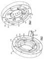
magnetic bearing assembly 30 is shown in more detail inFigures 2 and6 . Themagnetic bearing assembly 30 includes anannular lamination stack 34 supported within aring 36. Thering 36 is mounted in thehousing 14.Coils 38 cooperate with themagnetic stack 34 to generate a magnetic field in the air gaps between the stack and theshaft 20. In the example, four circumferentially spacedcoils 38 are mounted onto thelamination stack 34.Leads 40 electrically connect thecoils 38 to thecontroller 32, best shown inFigure 1 . - It is desirable to insulate the
coils 38 from one another and thelamination stack 34 to prevent electrical shorts within themagnetic bearing assembly 30. Thelamination stack 34 includescoil apertures 48 that extend betweenopposing sides lamination stack 34 to permit thecoils 38 to pass between theopposing sides coils 38 from one another and thelamination stack 34, thelamination stack 34 is overmoulded with aninsulation 52. Theinsulation 52, which is adhered to thelamination stack 34 during the overmoulding process, may be constructed from polyphenolin sulfide or PEEK, for example. Theinsulation 52 is selected to provide good moulding and insulation characteristic as well as resistance to refrigerant. - The
lamination stack 34 includes aninner diameter 50 within which theshaft 20 is arranged and anouter diameter 51 engaging thering 36. In the example shown, theinsulation 52 does not necessarily need to extend about or enclose the entire exterior of thelamination stack 34. Rather, theinsulation 52 is moulded about portions of theopposing sides inner diameter 50 beneath thecoils 38. - In one example, a
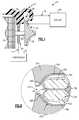
gap 59 in theinner diameter 50 interconnects with thecoil apertures 48, as shown inFigures 3 and4 . Theinsulation 52 includes anouter periphery 54 that is located radially inwardly from theouter diameter 51. In one example, theouter periphery 54 extends circumferentially betweencooling holes 46, which are in fluid communication with therefrigerant loop 26. Theinsulation 52 extends radially inwardly from theouter periphery 54 to aninner periphery 56, which terminates slightly radially outward from theinner diameter 50. Theinsulation 52 is provided in thegap 59 and extends about thecoil apertures 48 to provide acoil aperture lining 58 extending between theopposing sides Figure 5 . Awall 60 bisects thecoil apertures 48 and interconnects opposing sides of thecoil aperture lining 58 to provide first andsecond openings Figures 4, 5 and 7 . - Referring to
Figure 7 , adjoiningcoil portions 62 from thecoils 38 are provided in each of the first andsecond openings wall 60 insulates thecoil portion 62 from one another. Thecoil aperture lining 58, as well as a portion of theinsulation 52 extending between the outer andinner peripheries coils 38 from thelamination stack 34. It may be desirable to providetape 68 on the portions of thecoil portions 62 facing one another to provide further insulation between thecoil portions 62. - Another embodiment is shown if
Figure 8 . Like numerals indicate like elements. Adjoiningcoil portions 162 from thecoils 138 are provided in each of the first andsecond openings coil aperture 148. Thewall 160, which insulates thecoil portion 162 from one another, terminated in aterminal end 70 in or in proximity to thegap 159. The opening provided between theterminal end 70 and the coil aperture lining 158 interconnects the first andsecond openings coils 138 into thelamination stack 134. Thecoil aperture lining 158, as well as a portion of theinsulation 152 extending between the outer and inner peripheries 154, 156, insulates thecoils 138 from thelamination stack 134. It may be desirable to providetape 168 on the portions of thecoil portions 162 facing one another to provide further insulation between thecoil portions 162. - Although an example embodiment has been disclosed, a worker of ordinary skill in this art would recognize that certain modifications would come within the scope of the claims. For that reason, the following claims should be studied to determine their true scope and content.
Claims (18)
- A refrigerant compressor (10) comprising:an electric motor (16) configured to rotationally drive an impeller (18) via a shaft (20);a magnetic bearing assembly (30) including an inner diameter (50) within which the shaft is disposed, the magnetic bearing assembly having a lamination stack (34) with coil apertures (48) extending between opposing sides (42, 44), a continuous unitary insulation layer (52) provided within the coil apertures and the opposing sides, wherein the insulation layer provides a coil aperture lining (58) within the coil aperture (48) and includes a wall (60) within the coil aperture adjoining coil aperture lining and bisects the coil aperture into first and second openings (64, 66), and coils (38) disposed within and extending between the coil apertures; anda controller (32) in communication with the magnetic bearing and configured to energize the coils and provide a magnetic field rotationally supporting the shaft.
- The refrigerant compressor according to claim 1, comprising a housing (14) within which the electric motor (16) and impeller (18) are arranged, and a ring (36) supporting the magnetic bearing assembly (30) in the housing.
- The refrigerant compressor according to claim 2, wherein the lamination stack (34) includes an outer diameter (51) engaging the ring (36), and the insulation layer (52) includes an outer periphery (54) arranged radially inward of the outer diameter (51) and beneath the coils (38).
- The refrigerant compressor according to claim 1, wherein a coil portion (62) is disposed in each of the first and second openings (64, 66) and electrically isolated from one another by the wall (60).
- The refrigerant compressor according to claim 1, wherein the coil apertures (48) include a gap (59) facing radially inward providing a break at the inner diameter (50), and the insulation layer (52) filling the gap (59) with the coil aperture lining (58).
- The refrigerant compressor according to claim 1, comprising a refrigerant loop (26) in fluid communication with the impeller (18), and wherein the lamination stack (34) includes cooling holes (46) extending between the opposing sides (42, 44) which are in fluid communication with the refrigerant loop (26).
- The refrigerant compressor according to claim 1, wherein the continuous unitary insulation layer (52) is arranged on the opposing sides (42, 44) and within the coil apertures (48) providing the coil aperture lining (58); and
a coil portion (62) is disposed in each of the first and second openings (64, 66) and electrically isolated from one another by the wall (60). - The refrigerant compressor according to claim 7, wherein the insulation layer (52) includes an outer periphery (54) arranged radially inward of an outer diameter (51) of the lamination stack (34) and beneath the coils (38).
- The refrigerant compressor according to claim 7, wherein the coil apertures (48) include a gap (59) facing radially inward providing a break at an inner diameter (50) of the lamination stack (34), and the insulation layer (52) filling the gap with the coil aperture lining (58).
- The refrigerant compressor according to claim 9, wherein the wall (60) extends from the gap (59) radially outward to an opposite portion of the coil aperture lining (58).
- The refrigerant compressor according to claim 8, wherein cooling holes (46) are circumferentially spaced about the lamination stack (34) and extend between the opposing sides (42, 44), the insulation (52) including an outer periphery (54) that extends radially to the cooling holes.
- The refrigerant compressor according to claim 8, comprising a ring (36) engaging the outer diameter (51).
- The refrigerant compressor according to claim 8, wherein the coil apertures (148) include a gap (159) facing radially inward providing a break at an inner diameter of the lamination stack (134), and the wall (160) terminates in a terminal end (70) in proximity to the gap (159) providing an opening in the insulation interconnecting the first and second openings (164, 166).
- A bearing stack comprising:magnetic layers laminated to one another providing an annular body having opposing sides (42, 44), and including multiple coil apertures (48) circumferentially spaced about the annular body and extending between the opposing sides; anda continuous unitary insulation layer (52) arranged on the opposing sides and within the coil apertures providing a coil aperture lining (58), and including a wall (60) within the coil aperture adjoining coil aperture lining and bisecting the coil aperture into first and second openings (64, 66).
- The bearing stack according to claim 14, wherein the coil apertures (48) include a gap (59) facing radially inward providing a break at an inner diameter (50) of the annular body, and the insulation layer (52) filling the gap with the coil aperture lining (58).
- The bearing stack according to claim 15, wherein the wall (60) extends from the gap (59) radially outward to an opposite portion of the coil aperture lining (58).
- The bearing stack according to claim 14, comprising cooling holes (46) circumferentially spaced about the annular body and extending between the opposing sides (42, 44), the insulation (52) including an outer periphery (54) that extends radially to the cooling holes.
- The bearing stack according to claim 14, wherein the coil apertures (148) include a gap (159) facing radially inward providing a break at an inner diameter of the lamination stack (134), and the wall (160) terminates in a terminal end (70) in proximity to the gap providing an opening in the insulation (152) interconnecting the first and second openings (164, 166).
Applications Claiming Priority (1)
| Application Number | Priority Date | Filing Date | Title |
|---|---|---|---|
| PCT/US2010/043481WO2012015398A1 (en) | 2010-07-28 | 2010-07-28 | Refrigerant compressor magnetic bearing |
Publications (3)
| Publication Number | Publication Date |
|---|---|
| EP2599190A1 EP2599190A1 (en) | 2013-06-05 |
| EP2599190A4 EP2599190A4 (en) | 2014-12-03 |
| EP2599190B1true EP2599190B1 (en) | 2016-08-17 |
Family
ID=45530375
Family Applications (1)
| Application Number | Title | Priority Date | Filing Date |
|---|---|---|---|
| EP10855430.4AActiveEP2599190B1 (en) | 2010-07-28 | 2010-07-28 | Refrigerant compressor magnetic bearing |
Country Status (5)
| Country | Link |
|---|---|
| US (1) | US9624939B2 (en) |
| EP (1) | EP2599190B1 (en) |
| CN (1) | CN102959834B (en) |
| AU (1) | AU2010358053B2 (en) |
| WO (1) | WO2012015398A1 (en) |
Families Citing this family (5)
| Publication number | Priority date | Publication date | Assignee | Title |
|---|---|---|---|---|
| US10044240B2 (en)* | 2015-09-18 | 2018-08-07 | Mando Corporation | Three phase motor in which structure for preventing electrical short circuit is applied |
| CN110475977B (en)* | 2017-03-24 | 2022-04-26 | 江森自控科技公司 | Magnetic bearing motor compressor |
| EP3712434B1 (en) | 2019-03-20 | 2021-12-22 | Danfoss A/S | Check valve damping |
| US11698076B2 (en)* | 2021-02-15 | 2023-07-11 | Danfoss A/S | Refrigerant compressor including insulation for magnetic bearing assembly |
| CN112886731B (en)* | 2021-02-22 | 2025-04-11 | 珠海格力电器股份有限公司 | Magnetic suspension radial bearing stator, radial bearing, compressor, air conditioner |
Family Cites Families (19)
| Publication number | Priority date | Publication date | Assignee | Title |
|---|---|---|---|---|
| US3334255A (en)* | 1965-02-19 | 1967-08-01 | Robert W Peters | Electric motor |
| JP2844610B2 (en) | 1988-09-14 | 1999-01-06 | 松下電器産業株式会社 | Mold motor |
| US5095237A (en)* | 1990-03-20 | 1992-03-10 | Nova Corporation Of Alberta | Sectoral core for magnetic bearing |
| US5530307A (en) | 1994-03-28 | 1996-06-25 | Emerson Electric Co. | Flux controlled permanent magnet dynamo-electric machine |
| US5959382A (en)* | 1995-10-13 | 1999-09-28 | Milli Sensor Systems And Actuators, Inc. | Magnetic actuator and position control system |
| US5751077A (en) | 1997-03-27 | 1998-05-12 | Ford Global Technologies, Inc. | Fluid-cooled linear motor armature |
| US5924847A (en)* | 1997-08-11 | 1999-07-20 | Mainstream Engineering Corp. | Magnetic bearing centrifugal refrigeration compressor and refrigerant having minimum specific enthalpy rise |
| JPH1189130A (en) | 1997-09-08 | 1999-03-30 | Minebea Co Ltd | Motor construction |
| JP4144972B2 (en)* | 1999-05-31 | 2008-09-03 | 山洋電気株式会社 | Single bearing type permanent magnet motor and single bearing type fan motor |
| US6756713B2 (en)* | 2002-02-07 | 2004-06-29 | Ametek, Inc. | Insulated stator core with attachment features |
| US6954010B2 (en)* | 2002-05-06 | 2005-10-11 | Aerovironment, Inc. | Lamination cooling system |
| JP4122250B2 (en)* | 2003-03-31 | 2008-07-23 | 山洋電気株式会社 | Electronic component cooling system |
| DE20308665U1 (en)* | 2003-06-03 | 2004-12-30 | Minebea Co., Ltd. | Internal rotor electric motor |
| KR100529901B1 (en) | 2003-06-04 | 2005-11-22 | 엘지전자 주식회사 | The linear motor of a linear compressor |
| WO2005036727A1 (en)* | 2003-10-09 | 2005-04-21 | Matsushita Electric Industrial Co., Ltd. | Brushless dc motor coupled directly to ac source and electric apparatus using the same motor |
| US20070262668A1 (en)* | 2006-05-11 | 2007-11-15 | General Electric Company | Magnetic Bearings, Armatures for Magnetic Bearings, and Methods for Assembling the Same |
| US8156757B2 (en)* | 2006-10-06 | 2012-04-17 | Aff-Mcquay Inc. | High capacity chiller compressor |
| CN101158376B (en)* | 2007-11-15 | 2010-04-14 | 苏州大学 | Magnetic levitation motor bearing structure |
| US8310123B2 (en)* | 2008-07-28 | 2012-11-13 | Direct Drive Systems, Inc. | Wrapped rotor sleeve for an electric machine |
- 2010
- 2010-07-28EPEP10855430.4Apatent/EP2599190B1/enactiveActive
- 2010-07-28CNCN201080067397.6Apatent/CN102959834B/enactiveActive
- 2010-07-28WOPCT/US2010/043481patent/WO2012015398A1/enactiveApplication Filing
- 2010-07-28USUS13/640,771patent/US9624939B2/enactiveActive
- 2010-07-28AUAU2010358053Apatent/AU2010358053B2/ennot_activeCeased
Non-Patent Citations (1)
| Title |
|---|
| None* |
Also Published As
| Publication number | Publication date |
|---|---|
| AU2010358053B2 (en) | 2015-06-11 |
| US9624939B2 (en) | 2017-04-18 |
| AU2010358053A1 (en) | 2013-01-10 |
| EP2599190A1 (en) | 2013-06-05 |
| CN102959834A (en) | 2013-03-06 |
| EP2599190A4 (en) | 2014-12-03 |
| WO2012015398A1 (en) | 2012-02-02 |
| US20130039786A1 (en) | 2013-02-14 |
| CN102959834B (en) | 2017-10-20 |
Similar Documents
| Publication | Publication Date | Title |
|---|---|---|
| EP2599190B1 (en) | Refrigerant compressor magnetic bearing | |
| CN103282670B (en) | Pump assembly | |
| EP1246348B1 (en) | Synchronous induction motor and manufacturing method and drive unit for the same, and hermetic electric compressor | |
| EP2685611B1 (en) | Motor and electrical appliance provided with same | |
| JP6367875B2 (en) | Rotor structure of rotating electrical machine | |
| EP0967707A2 (en) | Divisible lamination brushless pump-motor having fluid cooling system | |
| US20140196277A1 (en) | Rotor Having a Squirrel Cage | |
| JP5831533B2 (en) | Compressor | |
| EP3026278B1 (en) | Magnetic bearing, rotary apparatus comprising such a magnetic bearing and method for manufacturing such a magnetic bearing | |
| KR20230112740A (en) | System and apparatus for axial field rotary energy device | |
| US11005325B2 (en) | Rotating electric machine, stator of rotating electric machine, and compressor | |
| US9866082B2 (en) | Rotor and a motor and compressor comprising the rotor | |
| US20150171673A1 (en) | System and method for retaining rotor structure in synchronous reluctance machine | |
| US6215212B1 (en) | Shaftless rotor construction | |
| US20250172322A1 (en) | Motor, compressor and air conditioner | |
| JP2015023750A (en) | Electric motor | |
| US7116024B2 (en) | Electric motor and method for its production | |
| US11949291B2 (en) | Motor having rotor with different core regions, compressor, and air conditioner having the motor | |
| JP4848665B2 (en) | Compressor | |
| WO2016177933A1 (en) | An end-shield for an electric machine | |
| JP6311471B2 (en) | Compressor | |
| US12313076B2 (en) | Multistage fluid compressor | |
| US11698076B2 (en) | Refrigerant compressor including insulation for magnetic bearing assembly | |
| JP7170855B2 (en) | Electric motor stators, electric motors, hermetic compressors and refrigeration cycle devices | |
| JP2012223068A (en) | Rotary electric machine |
Legal Events
| Date | Code | Title | Description |
|---|---|---|---|
| PUAI | Public reference made under article 153(3) epc to a published international application that has entered the european phase | Free format text:ORIGINAL CODE: 0009012 | |
| 17P | Request for examination filed | Effective date:20121030 | |
| AK | Designated contracting states | Kind code of ref document:A1 Designated state(s):AL AT BE BG CH CY CZ DE DK EE ES FI FR GB GR HR HU IE IS IT LI LT LU LV MC MK MT NL NO PL PT RO SE SI SK SM TR | |
| DAX | Request for extension of the european patent (deleted) | ||
| A4 | Supplementary search report drawn up and despatched | Effective date:20141105 | |
| RIC1 | Information provided on ipc code assigned before grant | Ipc:F16C 32/04 20060101ALI20141030BHEP Ipc:H02K 7/09 20060101AFI20141030BHEP Ipc:H02K 5/124 20060101ALI20141030BHEP Ipc:H02K 3/52 20060101ALN20141030BHEP Ipc:H02K 3/32 20060101ALN20141030BHEP Ipc:F04D 25/06 20060101ALN20141030BHEP Ipc:F04D 29/058 20060101ALI20141030BHEP | |
| RAP1 | Party data changed (applicant data changed or rights of an application transferred) | Owner name:DANFOSS A/S | |
| GRAP | Despatch of communication of intention to grant a patent | Free format text:ORIGINAL CODE: EPIDOSNIGR1 | |
| RIC1 | Information provided on ipc code assigned before grant | Ipc:F04D 29/058 20060101ALI20160121BHEP Ipc:F04D 25/06 20060101ALN20160121BHEP Ipc:H02K 7/09 20060101AFI20160121BHEP Ipc:H02K 3/52 20060101ALN20160121BHEP Ipc:H02K 5/124 20060101ALI20160121BHEP Ipc:H02K 3/32 20060101ALN20160121BHEP Ipc:F16C 32/04 20060101ALI20160121BHEP | |
| INTG | Intention to grant announced | Effective date:20160203 | |
| RIC1 | Information provided on ipc code assigned before grant | Ipc:H02K 5/124 20060101ALI20160122BHEP Ipc:H02K 3/52 20060101ALN20160122BHEP Ipc:F16C 32/04 20060101ALI20160122BHEP Ipc:H02K 3/32 20060101ALN20160122BHEP Ipc:H02K 7/09 20060101AFI20160122BHEP Ipc:F04D 25/06 20060101ALN20160122BHEP Ipc:F04D 29/058 20060101ALI20160122BHEP | |
| GRAS | Grant fee paid | Free format text:ORIGINAL CODE: EPIDOSNIGR3 | |
| GRAR | Information related to intention to grant a patent recorded | Free format text:ORIGINAL CODE: EPIDOSNIGR71 | |
| GRAA | (expected) grant | Free format text:ORIGINAL CODE: 0009210 | |
| INTG | Intention to grant announced | Effective date:20160624 | |
| AK | Designated contracting states | Kind code of ref document:B1 Designated state(s):AL AT BE BG CH CY CZ DE DK EE ES FI FR GB GR HR HU IE IS IT LI LT LU LV MC MK MT NL NO PL PT RO SE SI SK SM TR | |
| REG | Reference to a national code | Ref country code:GB Ref legal event code:FG4D | |
| REG | Reference to a national code | Ref country code:CH Ref legal event code:EP | |
| REG | Reference to a national code | Ref country code:IE Ref legal event code:FG4D | |
| REG | Reference to a national code | Ref country code:AT Ref legal event code:REF Ref document number:821897 Country of ref document:AT Kind code of ref document:T Effective date:20160915 | |
| REG | Reference to a national code | Ref country code:DE Ref legal event code:R096 Ref document number:602010035725 Country of ref document:DE | |
| REG | Reference to a national code | Ref country code:NL Ref legal event code:MP Effective date:20160817 | |
| REG | Reference to a national code | Ref country code:LT Ref legal event code:MG4D | |
| REG | Reference to a national code | Ref country code:AT Ref legal event code:MK05 Ref document number:821897 Country of ref document:AT Kind code of ref document:T Effective date:20160817 | |
| PG25 | Lapsed in a contracting state [announced via postgrant information from national office to epo] | Ref country code:LT Free format text:LAPSE BECAUSE OF FAILURE TO SUBMIT A TRANSLATION OF THE DESCRIPTION OR TO PAY THE FEE WITHIN THE PRESCRIBED TIME-LIMIT Effective date:20160817 Ref country code:IT Free format text:LAPSE BECAUSE OF FAILURE TO SUBMIT A TRANSLATION OF THE DESCRIPTION OR TO PAY THE FEE WITHIN THE PRESCRIBED TIME-LIMIT Effective date:20160817 Ref country code:NO Free format text:LAPSE BECAUSE OF FAILURE TO SUBMIT A TRANSLATION OF THE DESCRIPTION OR TO PAY THE FEE WITHIN THE PRESCRIBED TIME-LIMIT Effective date:20161117 Ref country code:FI Free format text:LAPSE BECAUSE OF FAILURE TO SUBMIT A TRANSLATION OF THE DESCRIPTION OR TO PAY THE FEE WITHIN THE PRESCRIBED TIME-LIMIT Effective date:20160817 Ref country code:HR Free format text:LAPSE BECAUSE OF FAILURE TO SUBMIT A TRANSLATION OF THE DESCRIPTION OR TO PAY THE FEE WITHIN THE PRESCRIBED TIME-LIMIT Effective date:20160817 Ref country code:NL Free format text:LAPSE BECAUSE OF FAILURE TO SUBMIT A TRANSLATION OF THE DESCRIPTION OR TO PAY THE FEE WITHIN THE PRESCRIBED TIME-LIMIT Effective date:20160817 | |
| PG25 | Lapsed in a contracting state [announced via postgrant information from national office to epo] | Ref country code:SE Free format text:LAPSE BECAUSE OF FAILURE TO SUBMIT A TRANSLATION OF THE DESCRIPTION OR TO PAY THE FEE WITHIN THE PRESCRIBED TIME-LIMIT Effective date:20160817 Ref country code:PL Free format text:LAPSE BECAUSE OF FAILURE TO SUBMIT A TRANSLATION OF THE DESCRIPTION OR TO PAY THE FEE WITHIN THE PRESCRIBED TIME-LIMIT Effective date:20160817 Ref country code:ES Free format text:LAPSE BECAUSE OF FAILURE TO SUBMIT A TRANSLATION OF THE DESCRIPTION OR TO PAY THE FEE WITHIN THE PRESCRIBED TIME-LIMIT Effective date:20160817 Ref country code:AT Free format text:LAPSE BECAUSE OF FAILURE TO SUBMIT A TRANSLATION OF THE DESCRIPTION OR TO PAY THE FEE WITHIN THE PRESCRIBED TIME-LIMIT Effective date:20160817 Ref country code:LV Free format text:LAPSE BECAUSE OF FAILURE TO SUBMIT A TRANSLATION OF THE DESCRIPTION OR TO PAY THE FEE WITHIN THE PRESCRIBED TIME-LIMIT Effective date:20160817 Ref country code:PT Free format text:LAPSE BECAUSE OF FAILURE TO SUBMIT A TRANSLATION OF THE DESCRIPTION OR TO PAY THE FEE WITHIN THE PRESCRIBED TIME-LIMIT Effective date:20161219 Ref country code:GR Free format text:LAPSE BECAUSE OF FAILURE TO SUBMIT A TRANSLATION OF THE DESCRIPTION OR TO PAY THE FEE WITHIN THE PRESCRIBED TIME-LIMIT Effective date:20161118 | |
| PG25 | Lapsed in a contracting state [announced via postgrant information from national office to epo] | Ref country code:EE Free format text:LAPSE BECAUSE OF FAILURE TO SUBMIT A TRANSLATION OF THE DESCRIPTION OR TO PAY THE FEE WITHIN THE PRESCRIBED TIME-LIMIT Effective date:20160817 Ref country code:RO Free format text:LAPSE BECAUSE OF FAILURE TO SUBMIT A TRANSLATION OF THE DESCRIPTION OR TO PAY THE FEE WITHIN THE PRESCRIBED TIME-LIMIT Effective date:20160817 | |
| REG | Reference to a national code | Ref country code:DE Ref legal event code:R097 Ref document number:602010035725 Country of ref document:DE | |
| PG25 | Lapsed in a contracting state [announced via postgrant information from national office to epo] | Ref country code:SK Free format text:LAPSE BECAUSE OF FAILURE TO SUBMIT A TRANSLATION OF THE DESCRIPTION OR TO PAY THE FEE WITHIN THE PRESCRIBED TIME-LIMIT Effective date:20160817 Ref country code:SM Free format text:LAPSE BECAUSE OF FAILURE TO SUBMIT A TRANSLATION OF THE DESCRIPTION OR TO PAY THE FEE WITHIN THE PRESCRIBED TIME-LIMIT Effective date:20160817 Ref country code:BG Free format text:LAPSE BECAUSE OF FAILURE TO SUBMIT A TRANSLATION OF THE DESCRIPTION OR TO PAY THE FEE WITHIN THE PRESCRIBED TIME-LIMIT Effective date:20161117 Ref country code:BE Free format text:LAPSE BECAUSE OF FAILURE TO SUBMIT A TRANSLATION OF THE DESCRIPTION OR TO PAY THE FEE WITHIN THE PRESCRIBED TIME-LIMIT Effective date:20160817 Ref country code:CZ Free format text:LAPSE BECAUSE OF FAILURE TO SUBMIT A TRANSLATION OF THE DESCRIPTION OR TO PAY THE FEE WITHIN THE PRESCRIBED TIME-LIMIT Effective date:20160817 Ref country code:DK Free format text:LAPSE BECAUSE OF FAILURE TO SUBMIT A TRANSLATION OF THE DESCRIPTION OR TO PAY THE FEE WITHIN THE PRESCRIBED TIME-LIMIT Effective date:20160817 | |
| PLBE | No opposition filed within time limit | Free format text:ORIGINAL CODE: 0009261 | |
| REG | Reference to a national code | Ref country code:FR Ref legal event code:PLFP Year of fee payment:8 | |
| STAA | Information on the status of an ep patent application or granted ep patent | Free format text:STATUS: NO OPPOSITION FILED WITHIN TIME LIMIT | |
| 26N | No opposition filed | Effective date:20170518 | |
| PG25 | Lapsed in a contracting state [announced via postgrant information from national office to epo] | Ref country code:SI Free format text:LAPSE BECAUSE OF FAILURE TO SUBMIT A TRANSLATION OF THE DESCRIPTION OR TO PAY THE FEE WITHIN THE PRESCRIBED TIME-LIMIT Effective date:20160817 | |
| REG | Reference to a national code | Ref country code:CH Ref legal event code:PL | |
| REG | Reference to a national code | Ref country code:IE Ref legal event code:MM4A | |
| PG25 | Lapsed in a contracting state [announced via postgrant information from national office to epo] | Ref country code:LI Free format text:LAPSE BECAUSE OF NON-PAYMENT OF DUE FEES Effective date:20170731 Ref country code:IE Free format text:LAPSE BECAUSE OF NON-PAYMENT OF DUE FEES Effective date:20170728 Ref country code:CH Free format text:LAPSE BECAUSE OF NON-PAYMENT OF DUE FEES Effective date:20170731 | |
| REG | Reference to a national code | Ref country code:FR Ref legal event code:PLFP Year of fee payment:9 | |
| PG25 | Lapsed in a contracting state [announced via postgrant information from national office to epo] | Ref country code:LU Free format text:LAPSE BECAUSE OF NON-PAYMENT OF DUE FEES Effective date:20170728 | |
| PG25 | Lapsed in a contracting state [announced via postgrant information from national office to epo] | Ref country code:MT Free format text:LAPSE BECAUSE OF NON-PAYMENT OF DUE FEES Effective date:20170728 | |
| PG25 | Lapsed in a contracting state [announced via postgrant information from national office to epo] | Ref country code:AL Free format text:LAPSE BECAUSE OF FAILURE TO SUBMIT A TRANSLATION OF THE DESCRIPTION OR TO PAY THE FEE WITHIN THE PRESCRIBED TIME-LIMIT Effective date:20160817 | |
| PG25 | Lapsed in a contracting state [announced via postgrant information from national office to epo] | Ref country code:MC Free format text:LAPSE BECAUSE OF FAILURE TO SUBMIT A TRANSLATION OF THE DESCRIPTION OR TO PAY THE FEE WITHIN THE PRESCRIBED TIME-LIMIT Effective date:20160817 Ref country code:HU Free format text:LAPSE BECAUSE OF FAILURE TO SUBMIT A TRANSLATION OF THE DESCRIPTION OR TO PAY THE FEE WITHIN THE PRESCRIBED TIME-LIMIT; INVALID AB INITIO Effective date:20100728 | |
| PG25 | Lapsed in a contracting state [announced via postgrant information from national office to epo] | Ref country code:CY Free format text:LAPSE BECAUSE OF NON-PAYMENT OF DUE FEES Effective date:20160817 | |
| PG25 | Lapsed in a contracting state [announced via postgrant information from national office to epo] | Ref country code:MK Free format text:LAPSE BECAUSE OF FAILURE TO SUBMIT A TRANSLATION OF THE DESCRIPTION OR TO PAY THE FEE WITHIN THE PRESCRIBED TIME-LIMIT Effective date:20160817 | |
| PG25 | Lapsed in a contracting state [announced via postgrant information from national office to epo] | Ref country code:TR Free format text:LAPSE BECAUSE OF FAILURE TO SUBMIT A TRANSLATION OF THE DESCRIPTION OR TO PAY THE FEE WITHIN THE PRESCRIBED TIME-LIMIT Effective date:20160817 | |
| PG25 | Lapsed in a contracting state [announced via postgrant information from national office to epo] | Ref country code:IS Free format text:LAPSE BECAUSE OF FAILURE TO SUBMIT A TRANSLATION OF THE DESCRIPTION OR TO PAY THE FEE WITHIN THE PRESCRIBED TIME-LIMIT Effective date:20161217 | |
| P01 | Opt-out of the competence of the unified patent court (upc) registered | Effective date:20230617 | |
| PGFP | Annual fee paid to national office [announced via postgrant information from national office to epo] | Ref country code:DE Payment date:20240604 Year of fee payment:15 | |
| PGFP | Annual fee paid to national office [announced via postgrant information from national office to epo] | Ref country code:GB Payment date:20250605 Year of fee payment:16 | |
| PGFP | Annual fee paid to national office [announced via postgrant information from national office to epo] | Ref country code:FR Payment date:20250623 Year of fee payment:16 |