EP2598313B1 - Method and apparatus for producing a three-dimensional component - Google Patents
Method and apparatus for producing a three-dimensional componentDownload PDFInfo
- Publication number
- EP2598313B1 EP2598313B1EP11779556.7AEP11779556AEP2598313B1EP 2598313 B1EP2598313 B1EP 2598313B1EP 11779556 AEP11779556 AEP 11779556AEP 2598313 B1EP2598313 B1EP 2598313B1
- Authority
- EP
- European Patent Office
- Prior art keywords
- component
- sensor values
- values
- building material
- sensor
- Prior art date
- Legal status (The legal status is an assumption and is not a legal conclusion. Google has not performed a legal analysis and makes no representation as to the accuracy of the status listed.)
- Revoked
Links
Images

Classifications
- B—PERFORMING OPERATIONS; TRANSPORTING
- B23—MACHINE TOOLS; METAL-WORKING NOT OTHERWISE PROVIDED FOR
- B23K—SOLDERING OR UNSOLDERING; WELDING; CLADDING OR PLATING BY SOLDERING OR WELDING; CUTTING BY APPLYING HEAT LOCALLY, e.g. FLAME CUTTING; WORKING BY LASER BEAM
- B23K31/00—Processes relevant to this subclass, specially adapted for particular articles or purposes, but not covered by only one of the preceding main groups
- B23K31/12—Processes relevant to this subclass, specially adapted for particular articles or purposes, but not covered by only one of the preceding main groups relating to investigating the properties, e.g. the weldability, of materials
- B—PERFORMING OPERATIONS; TRANSPORTING
- B22—CASTING; POWDER METALLURGY
- B22F—WORKING METALLIC POWDER; MANUFACTURE OF ARTICLES FROM METALLIC POWDER; MAKING METALLIC POWDER; APPARATUS OR DEVICES SPECIALLY ADAPTED FOR METALLIC POWDER
- B22F10/00—Additive manufacturing of workpieces or articles from metallic powder
- B22F10/20—Direct sintering or melting
- B22F10/28—Powder bed fusion, e.g. selective laser melting [SLM] or electron beam melting [EBM]
- B—PERFORMING OPERATIONS; TRANSPORTING
- B22—CASTING; POWDER METALLURGY
- B22F—WORKING METALLIC POWDER; MANUFACTURE OF ARTICLES FROM METALLIC POWDER; MAKING METALLIC POWDER; APPARATUS OR DEVICES SPECIALLY ADAPTED FOR METALLIC POWDER
- B22F10/00—Additive manufacturing of workpieces or articles from metallic powder
- B22F10/30—Process control
- B22F10/31—Calibration of process steps or apparatus settings, e.g. before or during manufacturing
- B—PERFORMING OPERATIONS; TRANSPORTING
- B22—CASTING; POWDER METALLURGY
- B22F—WORKING METALLIC POWDER; MANUFACTURE OF ARTICLES FROM METALLIC POWDER; MAKING METALLIC POWDER; APPARATUS OR DEVICES SPECIALLY ADAPTED FOR METALLIC POWDER
- B22F12/00—Apparatus or devices specially adapted for additive manufacturing; Auxiliary means for additive manufacturing; Combinations of additive manufacturing apparatus or devices with other processing apparatus or devices
- B22F12/90—Means for process control, e.g. cameras or sensors
- B—PERFORMING OPERATIONS; TRANSPORTING
- B23—MACHINE TOOLS; METAL-WORKING NOT OTHERWISE PROVIDED FOR
- B23K—SOLDERING OR UNSOLDERING; WELDING; CLADDING OR PLATING BY SOLDERING OR WELDING; CUTTING BY APPLYING HEAT LOCALLY, e.g. FLAME CUTTING; WORKING BY LASER BEAM
- B23K26/00—Working by laser beam, e.g. welding, cutting or boring
- B23K26/02—Positioning or observing the workpiece, e.g. with respect to the point of impact; Aligning, aiming or focusing the laser beam
- B23K26/06—Shaping the laser beam, e.g. by masks or multi-focusing
- B23K26/062—Shaping the laser beam, e.g. by masks or multi-focusing by direct control of the laser beam
- B23K26/0622—Shaping the laser beam, e.g. by masks or multi-focusing by direct control of the laser beam by shaping pulses
- B—PERFORMING OPERATIONS; TRANSPORTING
- B23—MACHINE TOOLS; METAL-WORKING NOT OTHERWISE PROVIDED FOR
- B23K—SOLDERING OR UNSOLDERING; WELDING; CLADDING OR PLATING BY SOLDERING OR WELDING; CUTTING BY APPLYING HEAT LOCALLY, e.g. FLAME CUTTING; WORKING BY LASER BEAM
- B23K26/00—Working by laser beam, e.g. welding, cutting or boring
- B23K26/70—Auxiliary operations or equipment
- B23K26/702—Auxiliary equipment
- B23K26/705—Beam measuring device
- B—PERFORMING OPERATIONS; TRANSPORTING
- B23—MACHINE TOOLS; METAL-WORKING NOT OTHERWISE PROVIDED FOR
- B23K—SOLDERING OR UNSOLDERING; WELDING; CLADDING OR PLATING BY SOLDERING OR WELDING; CUTTING BY APPLYING HEAT LOCALLY, e.g. FLAME CUTTING; WORKING BY LASER BEAM
- B23K31/00—Processes relevant to this subclass, specially adapted for particular articles or purposes, but not covered by only one of the preceding main groups
- B23K31/12—Processes relevant to this subclass, specially adapted for particular articles or purposes, but not covered by only one of the preceding main groups relating to investigating the properties, e.g. the weldability, of materials
- B23K31/125—Weld quality monitoring
- B—PERFORMING OPERATIONS; TRANSPORTING
- B29—WORKING OF PLASTICS; WORKING OF SUBSTANCES IN A PLASTIC STATE IN GENERAL
- B29C—SHAPING OR JOINING OF PLASTICS; SHAPING OF MATERIAL IN A PLASTIC STATE, NOT OTHERWISE PROVIDED FOR; AFTER-TREATMENT OF THE SHAPED PRODUCTS, e.g. REPAIRING
- B29C64/00—Additive manufacturing, i.e. manufacturing of three-dimensional [3D] objects by additive deposition, additive agglomeration or additive layering, e.g. by 3D printing, stereolithography or selective laser sintering
- B29C64/10—Processes of additive manufacturing
- B29C64/141—Processes of additive manufacturing using only solid materials
- B29C64/153—Processes of additive manufacturing using only solid materials using layers of powder being selectively joined, e.g. by selective laser sintering or melting
- B—PERFORMING OPERATIONS; TRANSPORTING
- B29—WORKING OF PLASTICS; WORKING OF SUBSTANCES IN A PLASTIC STATE IN GENERAL
- B29C—SHAPING OR JOINING OF PLASTICS; SHAPING OF MATERIAL IN A PLASTIC STATE, NOT OTHERWISE PROVIDED FOR; AFTER-TREATMENT OF THE SHAPED PRODUCTS, e.g. REPAIRING
- B29C64/00—Additive manufacturing, i.e. manufacturing of three-dimensional [3D] objects by additive deposition, additive agglomeration or additive layering, e.g. by 3D printing, stereolithography or selective laser sintering
- B29C64/30—Auxiliary operations or equipment
- B29C64/386—Data acquisition or data processing for additive manufacturing
- B29C64/393—Data acquisition or data processing for additive manufacturing for controlling or regulating additive manufacturing processes
- B—PERFORMING OPERATIONS; TRANSPORTING
- B33—ADDITIVE MANUFACTURING TECHNOLOGY
- B33Y—ADDITIVE MANUFACTURING, i.e. MANUFACTURING OF THREE-DIMENSIONAL [3-D] OBJECTS BY ADDITIVE DEPOSITION, ADDITIVE AGGLOMERATION OR ADDITIVE LAYERING, e.g. BY 3-D PRINTING, STEREOLITHOGRAPHY OR SELECTIVE LASER SINTERING
- B33Y10/00—Processes of additive manufacturing
- B—PERFORMING OPERATIONS; TRANSPORTING
- B33—ADDITIVE MANUFACTURING TECHNOLOGY
- B33Y—ADDITIVE MANUFACTURING, i.e. MANUFACTURING OF THREE-DIMENSIONAL [3-D] OBJECTS BY ADDITIVE DEPOSITION, ADDITIVE AGGLOMERATION OR ADDITIVE LAYERING, e.g. BY 3-D PRINTING, STEREOLITHOGRAPHY OR SELECTIVE LASER SINTERING
- B33Y30/00—Apparatus for additive manufacturing; Details thereof or accessories therefor
- B—PERFORMING OPERATIONS; TRANSPORTING
- B33—ADDITIVE MANUFACTURING TECHNOLOGY
- B33Y—ADDITIVE MANUFACTURING, i.e. MANUFACTURING OF THREE-DIMENSIONAL [3-D] OBJECTS BY ADDITIVE DEPOSITION, ADDITIVE AGGLOMERATION OR ADDITIVE LAYERING, e.g. BY 3-D PRINTING, STEREOLITHOGRAPHY OR SELECTIVE LASER SINTERING
- B33Y40/00—Auxiliary operations or equipment, e.g. for material handling
- B—PERFORMING OPERATIONS; TRANSPORTING
- B22—CASTING; POWDER METALLURGY
- B22F—WORKING METALLIC POWDER; MANUFACTURE OF ARTICLES FROM METALLIC POWDER; MAKING METALLIC POWDER; APPARATUS OR DEVICES SPECIALLY ADAPTED FOR METALLIC POWDER
- B22F10/00—Additive manufacturing of workpieces or articles from metallic powder
- B22F10/10—Formation of a green body
- B—PERFORMING OPERATIONS; TRANSPORTING
- B22—CASTING; POWDER METALLURGY
- B22F—WORKING METALLIC POWDER; MANUFACTURE OF ARTICLES FROM METALLIC POWDER; MAKING METALLIC POWDER; APPARATUS OR DEVICES SPECIALLY ADAPTED FOR METALLIC POWDER
- B22F12/00—Apparatus or devices specially adapted for additive manufacturing; Auxiliary means for additive manufacturing; Combinations of additive manufacturing apparatus or devices with other processing apparatus or devices
- B22F12/40—Radiation means
- B22F12/44—Radiation means characterised by the configuration of the radiation means
- B—PERFORMING OPERATIONS; TRANSPORTING
- B22—CASTING; POWDER METALLURGY
- B22F—WORKING METALLIC POWDER; MANUFACTURE OF ARTICLES FROM METALLIC POWDER; MAKING METALLIC POWDER; APPARATUS OR DEVICES SPECIALLY ADAPTED FOR METALLIC POWDER
- B22F12/00—Apparatus or devices specially adapted for additive manufacturing; Auxiliary means for additive manufacturing; Combinations of additive manufacturing apparatus or devices with other processing apparatus or devices
- B22F12/40—Radiation means
- B22F12/49—Scanners
- Y—GENERAL TAGGING OF NEW TECHNOLOGICAL DEVELOPMENTS; GENERAL TAGGING OF CROSS-SECTIONAL TECHNOLOGIES SPANNING OVER SEVERAL SECTIONS OF THE IPC; TECHNICAL SUBJECTS COVERED BY FORMER USPC CROSS-REFERENCE ART COLLECTIONS [XRACs] AND DIGESTS
- Y02—TECHNOLOGIES OR APPLICATIONS FOR MITIGATION OR ADAPTATION AGAINST CLIMATE CHANGE
- Y02P—CLIMATE CHANGE MITIGATION TECHNOLOGIES IN THE PRODUCTION OR PROCESSING OF GOODS
- Y02P10/00—Technologies related to metal processing
- Y02P10/25—Process efficiency
Definitions
- the inventionrelates to a method for producing a three-dimensional component by a laser melting method, in which the component takes place by sequential solidification of individual layers of building material solidifiable by the action of radiation by melting the building material, with the further features of the preamble of claim 1.
- the inventionalso relates to a device for carrying out this method and to the use of a visualization device for two- or multi-dimensional preferably 2D or 3D representation of component areas of generatively produced by radiation effect on powdered building material components in terms of component quality.
- the illustrated apparatus for selective laser powder processingcomprises a build platform with a powder bed, a powder coating system for applying a powder surface to the build platform, a laser whose focused laser beam strikes the powder surface and causes melting of the powder within a melt zone.
- the laser beamis directed with a scanner device over the powder surface.
- a detector for detecting electromagnetic radiationis provided, which is emitted or reflected from the powder surface and which cooperates with an optical system which follows the laser beam and is suitable for guiding the radiation in the direction of the detector.
- the detector of the known deviceis designed such that it can detect the electromagnetic radiation emitted or reflected by a mobile observation area on the powder surface, wherein the movable observation area is larger than the minimum laser spot of the laser beam. Thereby, the melt pool can be detected, which is generated in the powder bed.
- the size of the melting zonein particular the length and width and a length to width ratio can be determined.
- specific partscan be selected from the electromagnetic spectrum of the radiation emitted by the melt pool.
- the inventionhas the object of developing a method with the features of the preamble of claim 1 and an associated apparatus for performing the method such that the values detected with it can be evaluated more easily.
- This objectis achieved in that the sensor values recorded for evaluating the component quality are stored together with the coordinate values locating the sensor values in the component and displayed in the component by means of a visualization device in 2D or 3D representation with respect to its detection location.
- the objectis achieved in that the sensor values acquired for evaluating the component quality are stored together with the coordinate values located in the component and represented in the component by means of a visualization device in bi- and / or multidimensional representations relative to their detection location.
- the sensor devicemay preferably detect with respect to the dimension, shape and / or temperature of the detected in the melting area effects of point and / or line energy input.
- sensor values of a component planeare represented, which correspond to a layer which is solidified by a new coating with building material by the action of radiation.
- sensor values of a freely selectable component-sectional planeare represented which runs at an angle (for example at right angles or at an angle below 30 °) to a layer which is successively solidified by the action of radiation.
- the sectional planecan be freely selectable both in its angle and in its position within the notional installation space on the screen of the visualization device, in a manner similar to that customary in commercial 2D / 3D CAD computer programs
- the coordinate values localizing the sensor values in the componentcan at least partially be the component coordinates used to produce the component. It is both possible to locate or localize or associate the sensor values with a coordinate value both by using the construction coordinate values (the information underlying the construction process) and exclusively or additionally using other sensors detected during the construction process Make localization sensors.
- a coordinate assignment of the sensor valuestakes place via exposure or scanner data. Additionally or alternatively, it may also be advantageous if, during the areal acquisition of the entire construction plane or the section comprising the component cross-section, the coordinates of a radiation energy input of the component plane are detected and assigned to the sensor values and the position of the component plane (Z coordinate) is detected separately.
- Visualization devicesare now used in conjunction with x-ray and computed tomography technology and typically serve to represent sensor values which, by virtue of the above methods, are present in an existing, i. finished body can be detected metrologically.
- the inventionuses a visualization method and an associated visualization device (software) in conjunction with a generative one
- a manufacturing methodis used and is used to make it easier to represent values recorded during the construction process in the melt pool, in order to provide an operator of such a laser melting system with information immediately after completion and / or during the construction process as to whether the solidified component layers meet the requirements with regard to melting, Temperature profile, workpiece strength, etc. to meet. If a generatively produced component does not prove to be strong enough and gives rise later to a complaint by a user, then archived building history visualization information can be used to quickly check, for example, if a breakage of the tool was actually made according to the building codes or if there were deviations up or down (eg tolerance ranges).
- a two- or more-dimensional representationis used in claim 1, this means that either a two-dimensional image of the visualized sensor values is displayed, wherein the sensor values are displayed in a sectional plane, e.g. lie a component plane or a plane which is at an angle to the construction plane or in a 3D representation of the component is shown as transparent and matches the component quality based on the determined sensor values and the correlated coordinate values, e.g. Baukoordinaten 1976 is displayed.
- an optimized value in a first color, gray scale and / or surface structuringcan be represented and with respect to this optimized value deviating values upwards or downwards are displayed in color, with respect to the gray value or with respect to of the surface structure (eg the hatching type) are displayed differently. This allows a viewer of such a 2D or 3D image immediately to gain insight into whether the construction process has expired optimally or the component may have weaknesses.
- the coordinate values locating the sensor values in the componentmay be the construction coordinate values used to make the component. These are the values used to direct the laser beam above the powder surface, as well as values representing a Z coordinate with respect to the film number. However, it is also possible to recapture the coordinate values locating the sensor values in the component when acquiring the sensor values, i. to scan, with a suitable scanning method, the component surface just to be solidified and to store values corresponding to a solidification site (location of the energy input into the powder bed) in the layer. This can be done by either a surface detection of the entire construction level takes place or just a section of interest of the construction level is detected, which contains the component area.
- the sensor valuesare not detected directly at the moment of the energy input, but additionally or alternatively offset in time thereafter. If, for example, the temperature in the melt pool is recorded at a time T 0 (during energy input) and then later, for example 0.5 seconds, 1 second, 1.5 seconds or the like, conclusions about the heat flow in the sensor pool can be obtained from such sensor values to be visualized Obtain component during the construction process, for example, to avoid overheating phenomena in the case of very filigree component interior areas. Such temporally offset detection methods are addressed, for example, in microscopy as sampling microscopes.
- the device for carrying out the methodcomprises, in addition to the usual components of a laser melting system with a sensor device according to FIG WO 2007/147221 A1 additionally a memory device, in which the sensor values detected for evaluating the component quality are stored together with the sensor values locating coordinates in the component, and a visualization device connected to the memory device, by means of which the stored sensor values in For example, color or gray graduated 2D or 3D representation based on their detection value in the component can be displayed.
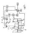
- FIG. 1shows a device according to the prior art, this device comprising a method for producing a three-dimensional component 1 by a laser melting method.
- the component 1is achieved by successive solidification of individual layers 2 (indicated as a dotted line) from building material 4 solidifiable by the action of a radiation 3 by melting the building material 4.
- the melting region 5 generated by a point or line-shaped energy inputis detected by a sensor device 6 (for example camera 11 and photodiode 12) with regard to its dimension, shape and / or temperature and the resulting sensor values are derived for the evaluation of a component quality.
- a sensor device 6for example camera 11 and photodiode 12
- the radiation 3is generated by a laser source 7 (laser). Subsequently deflected over a half-reflecting mirror 8 and directed via a scanner 9 with preferably a focusing lens targeted to the layer 2 of the building material 4 to be solidified.
- the radiation generated at the melting region 5goes this way in the opposite direction and penetrates the half-reflecting mirror 8 in a straight line, so that it reaches a beam splitter 10 and there deflected once to a first detector, preferably a camera 11 and the beam splitter 6 in a straight line penetrating to a second detector, such as a photodiode 12 is guided.
- the component 1 constructed in the construction area on a height-displaceable support 13 using a base plate 14is constructed in layers (cf., layer 2) in the powder bed of the pulverulent building material 4.
- a coater 15transports the building material 4 from a metering chamber 26 into the building area.
- the radiation 3is directed to rectilinear penetration of a one-side penetrable mirror 16 via the scanner 9 to the component 1.
- the radiation reflected by the componentis directed via the scanner 9 and the mirror 16 which is totally reflecting in this direction to a further deflection mirror 17 and finally to a detector of a sensor device 6, 11, 12, 18.
- This detectorsends a signal to a processor 19, preferably a microprocessor whose output reaches a memory 20.
- the laser 7is preferably provided with a beam manipulation device 21, which is designed, for example, in the manner of a mode diaphragm, a grating filter or other optical elements.
- This beam manipulation device 21is actuated via a controller 22 whose control data, as well as the processor data of the processor 19 stored in the memory 20, converge in a data linkage and / or data assignment unit 23.
- control data of the scanner 9 and / or control data relating to the height displacement of the carrier 13may preferably be collected via its servomotor 24 and associated with each other.
- control data of the coater of the coater 15 and / or the supply mechanism of building material to a corresponding device layer 2(this could be realized, for example, with the control data of the servo motor 25 of the metering chamber 26), the data link / data assignment unit 23 are supplied.
- a control module 27 of the scannercan also be arranged.
- the data (eg data tuples) collected in the data link / data allocation unit 23can then be assigned to one another further data processing system 28 further processed and / or visualized via a display element 29.
- a data processing system 28may also be provided an interface for a data storage.
- a display elementboth a screen, a projector or a holograph can be used.
- the sensor values detected for evaluating the component qualityare stored together with the coordinate values locating the sensor values in the component 1 and displayed by the visualization device 29 in two- and / or multi-dimensional representations relative to their detection location in the component 1.
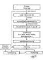
- FIG. 3an advantageous process flow of the method according to the invention is shown by way of example.
- the process controlacts on the laser 7 and / or the scanner 9 and regulates the properties of the laser beam 3 via the laser vector [n].
- the building material 4is exposed, whereby a melt or the melting region 5 is formed.
- From the melting region 5there is an emission of radiation which is detected by the sensor device 6, 11, 12, 18.
- the result of this detectionleads to an evaluation (for example of the type of length, width, area, etc.), which leads to an intermediate storage of the evaluation.
- This cached evaluationis subjected to a so-called mapping.
- This mappingis preferably based on definable / changeable mapping parameters (contrast, color, detector selection, threshold ranges, etc.).
- thisis displayed and / or stored via the visualization device 29.
- it is advantageous if the storage parameters and / or the representationare also based on the mapping parameters, ie the mapping parameters are also stored or displayed by the visualization device 29.
Landscapes
- Engineering & Computer Science (AREA)
- Chemical & Material Sciences (AREA)
- Materials Engineering (AREA)
- Physics & Mathematics (AREA)
- Optics & Photonics (AREA)
- Manufacturing & Machinery (AREA)
- Mechanical Engineering (AREA)
- Plasma & Fusion (AREA)
- Automation & Control Theory (AREA)
- Quality & Reliability (AREA)
- Analytical Chemistry (AREA)
- Length Measuring Devices By Optical Means (AREA)
- Radiation Pyrometers (AREA)
- Powder Metallurgy (AREA)
Description
Translated fromGermanDie Erfindung betrifft ein Verfahren zum Herstellen eines dreidimensionalen Bauteils durch ein Laserschmelzverfahren, bei welchem das Bauteil durch aufeinanderfolgendes Verfestigen einzelner Schichten aus durch Einwirkung einer Strahlung verfestigbarem Baumaterial durch Aufschmelzen des Baumaterials erfolgt, mit den weiteren Merkmalen des Oberbegriffes des Anspruches 1.The invention relates to a method for producing a three-dimensional component by a laser melting method, in which the component takes place by sequential solidification of individual layers of building material solidifiable by the action of radiation by melting the building material, with the further features of the preamble of claim 1.
Darüber hinaus betrifft die Erfindung noch eine Vorrichtung zur Durchführung dieses Verfahrens sowie die Verwendung einer Visualisierungseinrichtung zur zwei- oder mehrdimensionalen vorzugsweise 2D- oder 3D-Darstellung von Bauteilbereichen von generativ durch Strahlungseinwirkung auf pulverartiges Baumaterial hergestellten Bauteilen hinsichtlich ihrer Bauteilqualität.In addition, the invention also relates to a device for carrying out this method and to the use of a visualization device for two- or multi-dimensional preferably 2D or 3D representation of component areas of generatively produced by radiation effect on powdered building material components in terms of component quality.
Aus
Der Detektor der bekannten Vorrichtung ist derart ausgebildet, dass er die elektromagnetische Strahlung erfassen kann, die von einem beweglichen Beobachtungsbereich auf der Pulveroberfläche abgegeben oder reflektiert wird, wobei der bewegliche Beobachtungsbereich größer ist wie der minimale Laserfleck des Laserstrahls. Dadurch kann der Schmelzepool erfasst werden, der im Pulverbett erzeugt wird.The detector of the known device is designed such that it can detect the electromagnetic radiation emitted or reflected by a mobile observation area on the powder surface, wherein the movable observation area is larger than the minimum laser spot of the laser beam. Thereby, the melt pool can be detected, which is generated in the powder bed.
Über den Detektor kann die Größe der Schmelzzone, insbesondere die Länge und Breite und ein Längen zu Breite Verhältnis ermittelt werden. Darüber hinaus können aus dem elektromagnetischen Spektrum der vom Schmelzepool emittierten Strahlung spezifische Teile selektiert werden.About the detector, the size of the melting zone, in particular the length and width and a length to width ratio can be determined. In addition, specific parts can be selected from the electromagnetic spectrum of the radiation emitted by the melt pool.
Der Erfindung liegt die Aufgabe zugrunde, ein Verfahren mit den Merkmalen des Oberbegriffes des Anspruches 1 sowie eine zugehörige Vorrichtung zur Durchführung des Verfahrens derart weiterzubilden, dass die mit ihr erfassten Werte einfacher ausgewertet werden können. Diese Aufgabe wird dadurch gelöst, dass die zur Evaluierung der Bauteilqualität erfassten Sensorwerte zusammen mit den die Sensorwerte im Bauteil lokalisierenden Koordinatenwerte abgespeichert und mittels einer Visualisierungseinrichtung in 2D oder 3D-Darstellung bezogen auf ihren Erfassungsort im Bauteil dargestellt werden.The invention has the object of developing a method with the features of the preamble of claim 1 and an associated apparatus for performing the method such that the values detected with it can be evaluated more easily. This object is achieved in that the sensor values recorded for evaluating the component quality are stored together with the coordinate values locating the sensor values in the component and displayed in the component by means of a visualization device in 2D or 3D representation with respect to its detection location.
Mit anderen Worten wird die Aufgabe dadurch gelöst, dass die zur Evaluierung der Bauteilqualität erfassten Sensorwerte zusammen mit den die Sensorwerte im Bauteil lokalisierten Koordinatenwerten abgespeichert und mittels einer Visualisierungseinrichtung in zwei- und/oder mehrdimensionalen Darstellungen bezogen auf ihren Erfassungsort im Bauteil dargestellt werden. Die Sensorvorrichtung kann vorzugsweise hinsichtlich der Abmessung, Form und/oder Temperatur der im Schmelzbereich detektierten Auswirkungen des punkt- und/oder linienförmigen Energieeintrags erfassen.In other words, the object is achieved in that the sensor values acquired for evaluating the component quality are stored together with the coordinate values located in the component and represented in the component by means of a visualization device in bi- and / or multidimensional representations relative to their detection location. The sensor device may preferably detect with respect to the dimension, shape and / or temperature of the detected in the melting area effects of point and / or line energy input.
In einer bevorzugten Ausführungsform werden bei einer 2D-Darstellung Sensorwerte einer Bauteilebene dargestellt, die einer Schicht entsprechen, die von einer Neubeschichtung mit Baumaterial durch Strahlungseinwirkung verfestigt wird. Insbesondere ist es vorteilhaft, wenn bei einer 2D-Darstellung Sensorwerte einer frei wählbaren Bauteilschnittebene dargestellt werden, die winkelig (z.B. rechtwinklig oder einem Winkel unter 30°) zu einer durch Strahlungseinwirkung sukzessiv verfestigten Schicht verläuft. Insbesondere kann die Schnittebene sowohl in ihrem Winkel als auch in ihrer Lage innerhalb des fiktiven Bauraums auf dem Bildschirm der Visualisierungseinrichtung frei wählbar sein, ähnlich wie dies auch bei handelsüblichen 2D- /3D-CAD-Computerprogrammen üblich istIn a preferred embodiment, in a 2D representation, sensor values of a component plane are represented, which correspond to a layer which is solidified by a new coating with building material by the action of radiation. In particular, it is advantageous if, in a 2D representation, sensor values of a freely selectable component-sectional plane are represented which runs at an angle (for example at right angles or at an angle below 30 °) to a layer which is successively solidified by the action of radiation. In particular, the sectional plane can be freely selectable both in its angle and in its position within the notional installation space on the screen of the visualization device, in a manner similar to that customary in commercial 2D / 3D CAD computer programs
Ferner ist es vorteilhaft, wenn bei einer zwei- und/oder mehrdimensionalen Darstellung ausschließlich Sensorwerte visuell dargestellt und/oder hervorgehoben werden, die Bauteilbereiche repräsentieren, die gegenüber wenigstens einem einen festlegbaren (vordefinierten) Sollverfestigungsgrad oder Solltemperaturwert oder Solldichtewert einen abweichenden, insbesondere reduzierten Verfestigungsgrad oder Temperaturwert oder Dichtewert zeigen. Ebenso ist es möglich, neben dem Verfestigungsgrad, dem Temperaturwert und dem Dichtewert auch einen Sollenergieeintrag und/oder Sollschmelzpoolabmessungen für die Abweichungsdarstellung und/oder Hervorhebung zugrundezulegen.Furthermore, it is advantageous if, in a two- and / or multi-dimensional representation, only sensor values are visually displayed and / or highlighted, which represent component areas which are opposite at least one of a definable (Predefined) Sollverfestigungsgrad or setpoint temperature value or setpoint density value show a deviating, in particular reduced degree of solidification or temperature value or density value. It is likewise possible, in addition to the degree of solidification, the temperature value and the density value, to also base on a desired energy input and / or desired melt pool dimensions for the deviation representation and / or highlighting.
Die Hervorhebung in diese Bereiche kann beispielsweise durch eine gezielte Wahl unterschiedlicher Farben, Graustufen, Transparenzgrade und/oder hinsichtlich einer Flächenstrukturierung (Schraffurart wie gepunktet, in unterschiedlichen Winkeln jeweils schräg liniert, etc.) erfolgen.The highlighting in these areas, for example, by a targeted choice of different colors, gray levels, degrees of transparency and / or in terms of a surface structuring (hatching as dotted, each obliquely lined at different angles, etc.) take place.
Ferner können die die Sensorwerte im Bauteil lokalisierenden Koordinatenwerte zumindest teilweise die zur Herstellung des Bauteils verwendeten Bauteilkoordinaten sein. Es ist sowohl möglich, die Verortung bzw. die Lokalisierung oder Zuordnung der Sensorwerte zu einem Koordinatenwert sowohl mittels der Verwendung der Baukoordinatenwerte (der Informationen, die dem Bauprozess zugrunde liegen), als auch ausschließlich oder zusätzlich unter Verwendung von während des Bauprozesses mittels weiterer Sensoren detektierter Lokalisierungssensoren vorzunehmen.Furthermore, the coordinate values localizing the sensor values in the component can at least partially be the component coordinates used to produce the component. It is both possible to locate or localize or associate the sensor values with a coordinate value both by using the construction coordinate values (the information underlying the construction process) and exclusively or additionally using other sensors detected during the construction process Make localization sensors.
In einer weiteren vorteilhaften Ausführungsform erfolgt eine Koordinatenzuordnung der Sensorwerte über Belichtungs- oder Scannerdaten. Zusätzlich oder alternativ kann es auch vorteilhaft sein, wenn bei der flächigen Erfassung der gesamten Bauebene oder des den Bauteilquerschnitt umfassenden Ausschnittes die Koordinaten eines Strahlungs-Energieeintrages der Bauteilebene erfasst und den Sensorwerten zuordnet und die Lage der Bauteilebene (Z-Koordinate) gesondert erfasst wird.In a further advantageous embodiment, a coordinate assignment of the sensor values takes place via exposure or scanner data. Additionally or alternatively, it may also be advantageous if, during the areal acquisition of the entire construction plane or the section comprising the component cross-section, the coordinates of a radiation energy input of the component plane are detected and assigned to the sensor values and the position of the component plane (Z coordinate) is detected separately.
Visualisierungseinrichtungen werden heute in Verbindung mit der Röntgen- und Computertomogramm-Technologie verwendet und dienen in der Regel dazu, Sensorwerte darzustellen, die aufgrund der genannten Verfahren in einem vorhandenen, d.h. fertig vorliegenden Körper messtechnisch erfasst werden.Visualization devices are now used in conjunction with x-ray and computed tomography technology and typically serve to represent sensor values which, by virtue of the above methods, are present in an existing, i. finished body can be detected metrologically.
Die Erfindung setzt erstmalig ein Visualisierungsverfahren und eine zugehörige Visualisierungsvorrichtung (Software) in Verbindung mit einem generativen Herstellungsverfahren ein und wird dazu verwendet, beim Bauvorgang im Schmelzepool erfasste Werte griffiger darzustellen, um unmittelbar nach Fertigstellung und/oder noch während des Bauvorganges einer Bedienungsperson einer derartigen Laserschmelzanlage Aufschluss darüber zu geben, ob die verfestigten Bauteilschichten den an das Bauteil gestellten Anforderungen hinsichtlich Aufschmelzung, Temperaturverlauf, Werkstückfestigkeit etc. zu genügen. Sollte ein generativ hergestelltes Bauteil sich nicht als fest genug erweisen und irgendwann später Anlass zur Beanstandung durch einen Benutzer geben, dann können z.B. archivierte bauhistorische Visualisierungsinformationen dazu herangezogen werden, um sehr schnell zu überprüfen, ob z.B. eine Bruchstelle des Werkzeuges entsprechend den Bauvorschriften tatsächlich hergestellt wurde oder ob es Abweichungen nach oben oder unten (z.B. von Toleranzbereichen) gab. Insbesondere dann, wenn innerhalb des Bauteils filigrane Strukturen vorliegen, kann überprüft werden, ob dort der Aufschmelzungsgrad, der Temperaturverlauf nach Wärmesenken, die Bauteildichte und dergleichen so eingestellt waren, dass Bruch vermieden werden sollen. Für zukünftige Bauvorhaben können dann derartige Erkenntnisse dazu herangezogen werden, um Werkstückbruch und/oder Materialversagen zu vermeiden.For the first time, the invention uses a visualization method and an associated visualization device (software) in conjunction with a generative one A manufacturing method is used and is used to make it easier to represent values recorded during the construction process in the melt pool, in order to provide an operator of such a laser melting system with information immediately after completion and / or during the construction process as to whether the solidified component layers meet the requirements with regard to melting, Temperature profile, workpiece strength, etc. to meet. If a generatively produced component does not prove to be strong enough and gives rise later to a complaint by a user, then archived building history visualization information can be used to quickly check, for example, if a breakage of the tool was actually made according to the building codes or if there were deviations up or down (eg tolerance ranges). In particular, if there are filigree structures within the component, it can be checked whether there the degree of fusion, the temperature profile after heat sinks, the component density and the like were set so that breakage should be avoided. For future construction projects such findings can then be used to avoid workpiece fracture and / or material failure.
Wenn im Anspruch 1 von einer zwei- oder mehrdimensionalen Darstellung gesprochen wird, so bedeutet dies, dass entweder ein zweidimensionales Bild der visualisierten Sensorwerte dargestellt wird, wobei die Sensorwerte in einer Schnittebene, z.B. einer Bauteilebene liegen oder einer Ebene, die winkelig zur Bauebene verläuft oder bei einer 3D-Darstellung das Bauteil gleichsam transparent dargestellt wird und Abgleichungen der Bauteilqualität-basierend auf den ermittelten Sensorwerten und den dazu korrelierten Koordinatenwerten, z.B. Baukoordinatenwerten dargestellt wird.When a two- or more-dimensional representation is used in claim 1, this means that either a two-dimensional image of the visualized sensor values is displayed, wherein the sensor values are displayed in a sectional plane, e.g. lie a component plane or a plane which is at an angle to the construction plane or in a 3D representation of the component is shown as transparent and matches the component quality based on the determined sensor values and the correlated coordinate values, e.g. Baukoordinatenwerten is displayed.
In Weiterbildung des Verfahrens ist es möglich, bei einer 2D- oder 3D-Darstellung ausschließlich Sensorwerte visuell herauszufiltern, die Bauteilbereiche repräsentieren, die gegenüber einem festlegbaren Sollverfestigungsgrad einen abweichenden, insbesondere reduzierten Verfestigungsgrad haben. Gleiches gilt natürlich auch für Darstellungen beispielsweise der Schmelztemperatur, der Dichte und dergleichen.In a further development of the method, it is possible to visually filter out only sensor values in a 2D or 3D representation, which represent component regions which have a deviating, in particular reduced, degree of consolidation compared with a definable nominal degree of solidification. Of course, the same applies to illustrations of, for example, the melting temperature, the density and the like.
Dabei kann ein optimierter Wert in einer ersten Farbe, Graustufe und/oder Flächenstrukturierung dargestellt werden und bezogen auf diesen optimierten Wert nach unten oder oben abweichende Werte farblich, hinsichtlich des Grauwertes bzw. hinsichtlich der Flächenstruktur (z.B. der Schraffurart) unterschiedlich dargestellt werden. Dies ermöglicht es einem Betrachter eines solchen 2D- oder 3D-Bildes sofort Erkenntnisse darüber zu gewinnen, ob der Bauvorgang optimal abgelaufen ist oder das Bauteil unter Umständen Schwächen aufweist.In this case, an optimized value in a first color, gray scale and / or surface structuring can be represented and with respect to this optimized value deviating values upwards or downwards are displayed in color, with respect to the gray value or with respect to of the surface structure (eg the hatching type) are displayed differently. This allows a viewer of such a 2D or 3D image immediately to gain insight into whether the construction process has expired optimally or the component may have weaknesses.
Die die Sensorwerte im Bauteil lokalisierenden Koordinatenwerte können die zur Herstellung des Bauteils verwendeten Baukoordinatenwerte sein. Dies sind die Werte, die dazu herangezogen werden, um den Laserstrahl Ober die Pulveroberfläche zu leiten sowie Werte, die eine Z-Koordinate hinsichtlich der Schichtnummer repräsentieren. Es ist aber auch möglich, die die Sensorwerte im Bauteil lokalisierenden Koordinatenwerte bei der Erfassung der Sensorwerte neu zu gewinnen, d.h. mit einem geeigneten Abtastverfahren die gerade zur Verfestigung anstehende Bauteiloberfläche abzutasten und Werte abzuspeichern, die einen Verfestigungsort (Ort der Energieeintragung in das Pulverbett) in der Schicht entsprechen. Dies kann dadurch geschehen, dass entweder eine flächige Erfassung der gesamten Bauebene erfolgt oder eben nur ein interessierender Ausschnitt der Bauebene erfasst wird, der den Bauteilbereich enthält.The coordinate values locating the sensor values in the component may be the construction coordinate values used to make the component. These are the values used to direct the laser beam above the powder surface, as well as values representing a Z coordinate with respect to the film number. However, it is also possible to recapture the coordinate values locating the sensor values in the component when acquiring the sensor values, i. to scan, with a suitable scanning method, the component surface just to be solidified and to store values corresponding to a solidification site (location of the energy input into the powder bed) in the layer. This can be done by either a surface detection of the entire construction level takes place or just a section of interest of the construction level is detected, which contains the component area.
Im Rahmen der Erfindung ist auch vorgesehen, die Sensorwerte nicht unmittelbar im Moment des Energieeintrages zu erfassen, sondern zusätzlich oder alternativ zeitlich versetzt danach. Wird z.B. die Temperatur im Schmelzepool zu einem Zeitpunkt T0 (beim Energieeintrag) und dann zeitlich danach, z.B. 0,5 Sekunden, 1 Sekunde, 1,5 Sekunden oder dergleichen erfasst, dann lassen sich aus derartigen zu visualisierenden Sensorwerten Aufschlüsse über den Wärmefluss im Bauteil beim Bauvorgang gewinnen, um z.B. bei sehr filigranen Bauteilinnenbereichen Überhitzungserscheinungen zu vermeiden. Derartige zeitlich versetzte Erfassungsverfahren werden z.B. in der Mikroskopie als Sampling Microscope -Verfahren angesprochen.In the context of the invention, it is also provided that the sensor values are not detected directly at the moment of the energy input, but additionally or alternatively offset in time thereafter. If, for example, the temperature in the melt pool is recorded at a time T0 (during energy input) and then later, for example 0.5 seconds, 1 second, 1.5 seconds or the like, conclusions about the heat flow in the sensor pool can be obtained from such sensor values to be visualized Obtain component during the construction process, for example, to avoid overheating phenomena in the case of very filigree component interior areas. Such temporally offset detection methods are addressed, for example, in microscopy as sampling microscopes.
Die Vorrichtung zur Durchführung des Verfahrens umfasst neben den üblichen Komponenten einer Laserschmelzanlage mit einer Sensorvorrichtung gemäß
Die Erfindung ist anhand eines Ausführungsbeispiels in den Zeichnungsfiguren näher erläutert. Diese zeigen
- Fig. 1
- eine schematische Darstellung eines koaxialen Überwachungsprozesssystems unter Verwendung zweier Vektoren gemäß dem Stand der Technik;
- Fig. 2
- eine schematische Darstellung einer typischen selektiven Laserprozessmaschine mit erfindungsgemäßen Mitteln zur Erfassung und Auswertung der Sensorwerte;
- Fig. 3
- ein Flussdiagramm, das wesentliche Prozessabläufe eines bevorzugten erfindungsgemäßen Verfahrens darstellt.
- Fig. 1
- a schematic representation of a coaxial monitoring process system using two vectors according to the prior art;
- Fig. 2
- a schematic representation of a typical selective laser processing machine with inventive means for detection and evaluation of the sensor values;
- Fig. 3
- a flowchart illustrating essential processes of a preferred method according to the invention.
In Zeichnungsfigur 1 ist eine Vorrichtung gemäß dem Stand der Technik dargestellt, wobei diese Vorrichtung ein Verfahren zum Herstellen eines dreidimensionalen Bauteils 1 durch ein Laserschmelzverfahren umfasst. Das Bauteil 1 wird durch aufeinanderfolgendes Verfestigen einzelner Schichten 2 (als Strichlinie angedeutet) aus durch Einwirkung einer Strahlung 3 verfestigbaren Baumaterials 4 durch Aufschmelzen des Baumaterials 4 erreicht. Der durch einen punkt- oder linienförmigen Energieeintrag erzeugte Schmelzbereich 5 wird durch eine Sensorvorrichtung 6 (z.B. Kamera 11 und Fotodiode 12) hinsichtlich seiner Abmessung, Form und/oder Temperatur erfasst und die daraus resultierenden Sensorwerte zur Evaluierung einer Bauteilqualität hergeleitet.FIG. 1 shows a device according to the prior art, this device comprising a method for producing a three-dimensional component 1 by a laser melting method. The component 1 is achieved by successive solidification of individual layers 2 (indicated as a dotted line) from building material 4 solidifiable by the action of a
In der dargestellten Ausführung des Standes der Technik gemäß
In Zeichnungsfigur 2 ist nun die Erweiterung des aus dem Stand der Technik bekannten Systems dargestellt. Das im Baubereich auf einen höhenverlagerbaren Träger 13 unter Verwendung einer Basisplatte 14 auf diese aufgebaute Bauteil 1 wird schichtweise (vgl. Schicht 2) im Pulverbett des pulverförmigen Baumaterials 4 aufgebaut. Eine Beschichtereinrichtung 15 transportiert das Baumaterial 4 aus einer Dosierkammer 26 in den Baubereich.In drawing figure 2, the extension of the known from the prior art system is now shown. The component 1 constructed in the construction area on a height-
Ausgehend von einem Laser 7 wird die Strahlung 3 nach geradlinigem Durchdringen eines einseitig durchdringbaren Spiegel 16 über den Scanner 9 auf das Bauteil 1 gerichtet. Die vom Bauteil reflektierte Strahlung wird über den Scanner 9 und den in dieser Richtung total reflektierenden Spiegel 16 auf einen weiteren Umlenkspiegel 17 und schließlich zu einem Detektor einer Sensorvorrichtung 6, 11, 12, 18 gelenkt. Dieser Detektor gibt ein Signal an einen Prozessor 19, vorzugsweise einem Mikroprozessor weiter, dessen Output zu einem Speicher 20 gelangt.Starting from a
Der Laser 7 ist vorzugsweise mit einer Strahlmanipulationseinrichtung 21 versehen, die beispielsweise nach Art einer Modenblende, einem Gitterfilter oder anderer optischer Elemente ausgebildet ist. Diese Strahlmanipulationseinrichtung 21 wird über einen Controller 22 angesteuert, dessen Steuerdaten ebenso wie die im Speicher 20 bevorrateten Prozessordaten des Prozessors 19 in einer Datenverknüpfungs- und/oder Datenzuordnungseinheit 23 zusammenlaufen. Ebenfalls können an der Datenverknüpfungs-/Datenzuordnungseinheit 23 Steuerdaten des Scanners 9 und/oder Steuerdaten bezüglich der Höhenverlagerung des Trägers 13 vorzugsweise über seinen Stellmotor 24 gesammelt und einander zugeordnet werden. Selbstverständlich können auch Steuerdaten des Beschichters der Beschichtereinrichtung 15 und/oder des Zuführmechanismus an Baumaterial zu einer entsprechenden Bauteilschicht 2 (dies wäre beispielsweise mit den Steuerdaten des Stellmotors 25 der Dosierkammer 26 realisierbar), der Datenverknüpfungs-/Datenzuordnungseinheit 23 zugeführt werden. Zwischen dem Scanner 9 und der Datenverknüpfungs-/Datenzuordnungseinheit 23 kann auch ein Steuermodul 27 des Scanners angeordnet sein. Die in der Datenverknüpfungs-/Datenzuordnungseinheit 23 gesammelten, einander zugeordneten Daten (z.B. Datentupel) können dann in einer weiteren Datenverarbeitungsanlage 28 weiterverarbeitet und/oder über ein Darstellungselement 29 visualisiert werden. Statt einer Datenverarbeitungsanlage 28 kann auch eine Schnittstelle für einen Datenspeicher vorgesehen sein. Als Darstellungselement kann sowohl ein Bildschirm, ein Beamer oder ein Holograph verwendet werden.The
Schließlich werden die zur Evaluierung der Bauteilqualität erfassten Sensorwerte zusammen mit den die Sensorwerte im Bauteil 1 lokalisierenden Koordinatenwerten abgespeichert und mittels der Visualisierungseinrichtung 29 in zwei- und/oder mehrdimensionalen Darstellungen bezogen auf ihren Erfassungsort im Bauteil 1 dargestellt.Finally, the sensor values detected for evaluating the component quality are stored together with the coordinate values locating the sensor values in the component 1 and displayed by the
In Zeichnungsfigur 3 ist beispielhaft ein vorteilhafter Prozessablauf des erfindungsgemäßen Verfahrens dargestellt. Die Prozesssteuerung wirkt auf den Laser 7 und/oder den Scanner 9 ein und regelt über den Laservektor [n] die Eigenschaften des Laserstrahls 3. Ausgehend vom Scanner 9 wird das Baumaterial 4 belichtet, wodurch sich eine Schmelze bzw. der Schmelzbereich 5 bildet. Aus dem Schmelzbereich 5 erfolgt eine Emission an Strahlung, die durch die Sensorvorrichtung 6, 11, 12, 18 detektiert wird. Das Ergebnis dieser Detektion führt zu einer Auswertung (z.B. nach Art der Länge, Breite, Fläche etc.), die zu einer Zwischenspeicherung der Auswertung führt. Diese zwischengespeicherte Auswertung wird einem so genannten Mapping unterzogen. Diesem Mapping liegen vorzugsweise definierbare / veränderbare Mappingparameter (Kontrast, Farbe, Detektorwahl, Schwellwertbereiche, etc.) zugrunde. Nach dem Mapping wird dieses über die Visualisierungseinrichtung 29 dargestellt und/oder gespeichert. Hierbei ist es von Vorteil, wenn der Speicherung und/oder der Darstellung auch die Mappingparameter zugrunde liegen, d.h. auch die Mappingparameter gespeichert werden bzw. von der Visualisierungsvorrichtung 29 mit angezeigt werden.In drawing figure 3 an advantageous process flow of the method according to the invention is shown by way of example. The process control acts on the
- 11
- Bauteilcomponent
- 22
- Schichtlayer
- 33
- Strahlungradiation
- 44
- Baumaterialbuilding materials
- 55
- Schmelzbereichmelting range
- 66
- Sensorvorrichtungsensor device
- 77
- Laserlaser
- 88th
- halbreflektierender Spiegelsemi-reflective mirror
- 99
- Scannerscanner
- 1010
- Strahlenteilerbeamsplitter
- 1111
- Kameracamera
- 1212
- Fotodiodephotodiode
- 1313
- Trägercarrier
- 1414
- Basisplattebaseplate
- 1515
- BeschichtereinrichtungBeschichtereinrichtung
- 1616
- Spiegelmirror
- 1717
- Spiegelmirror
- 1818
- Sensorvorrichtungsensor device
- 1919
- Prozessorprocessor
- 2020
- SpeicherStorage
- 2121
- StrahlmanipulationseinrichtungBeam manipulation device
- 2222
- Controller v. 21Controller v. 21
- 2323
- Datenverknüpfungs-/DatenzuordnungseinheitDatenverknüpfungs- / data allocation unit
- 2424
- Stellmotor v. 13Actuator v. 13
- 2525
- Stellmotor v. 26Actuator v. 26
- 2626
- Dosierkammermetering
- 2727
- Steuermodulcontrol module
- 2828
- DatenverarbeitungsanlageData processing system
- 2929
- Visualisierungseinrichtungvisualiser
Claims (15)
- A method for producing a three-dimensional component (1) by a laser melting process, in which the component (1) is produced by successive solidification of individual layers of building material (4) which can be solidified by the action of radiation, by fusing the building material (4), wherein the melt region (5) created by a point-and/or line-shaped energy influx is captured by a sensor device (6, 11, 12, 18) and sensor values for evaluating component quality are derived therefrom,
characterized in that
the sensor values captured for evaluating the component quality are stored together with the coordinate values localizing the sensor values in the component (1) and are displayed by means of a visualization apparatus (29) in a two-dimensional and/or multidimensional representation in respect of the capture location thereof in the component. - The method as claimed in claim 1,
characterized in that
sensor values of a component plane are displayed in the case of a 2D representation, which sensor values correspond to a layer (2) which is solidified by the action of radiation prior to a new deposition of building material (4). - The method as claimed in claim 1,
characterized in that
sensor values of a freely selectable component sectional plane are displayed in the case of a 2D representation, which plane extends at an angle to a layer successively solidified by the action of radiation. - The method as claimed in one of claims 1-3,
characterized in that
in the case of a two-dimensional and/or multidimensional representation only sensor values are displayed visually and/or highlighted which represent component regions which, compared to at least one definable intended degree of solidification or intended temperature value or intended density value, have a deviating, more particularly reduced, degree of solidification, temperature value or density value or exhibit deviations with respect to an intended energy influx or intended melt pool dimensions. - The method as claimed in one of the preceding claims,
characterized in that
in order to display the sensor values a sensor value representing an optimized value with respect to the building material is displayed in a first color, a first grayscale value, a first degree of transparency and/or with a first areal structure and values deviating upward or downward from this optimized value are displayed differently in terms of color, grayscale value, degree of transparency and/or in respect of an areal structure. - The method as claimed in one of the preceding claims,
characterized in that
the coordinate values localizing the sensor values in the component (1) at least in part are the build coordinate values used to produce the component. - The method as claimed in one of the preceding claims,
characterized in that
the coordinate values localizing the sensor values in the component (1) at least in part are newly obtained when capturing the sensor values. - The method as claimed in claim 7,
characterized in that
the coordinate values localizing the sensor values in the component (1) are obtained by an areal capture of either the whole build plane or a section of the build plane comprising the component region. - The method as claimed in one of the preceding claims,
characterized in that
coordinates are assigned to the sensor values by means of exposure data or scanner data. - The method as claimed in one of the preceding claims,
characterized in that
the capture of at least some of the sensor values takes place with a time delay with respect to the time of the energy influx and the values displayed by the visualization exhibit a time profile of the thermal behavior of the melt region (sampling method). - The method as claimed in one of the preceding claims,
characterized in that
in respect of the energy influx a plurality of sensor values with different time lags from the energy influx are established at one and the same point in the component plane. - A device for carrying out the method as claimed in one of claims 1-11, namely a laser melting device, in which a component (1) is produced by successive solidification of individual layers (2) of building material (4) that can be solidified by the action of radiation (3), more particularly laser radiation, by fusing the building material (4), wherein the melt region (5) created by a point- and/or line-shaped energy influx can be captured by a sensor device (6, 11, 12, 18) in respect of its dimensions, shape and/or temperature and sensor values for evaluating component quality can be derived therefrom,
characterized by- a storage apparatus, in which the sensor values captured for evaluating the component quality can be stored together with the coordinate values localizing sensor values in the component (1), and- a visualization apparatus (29), which is connected to the storage medium and by means of which it is possible to display the stored sensor values in a two-dimensional or multidimensional colored representation in respect of the capture location thereof in the component (1). - The device as claimed in claim 12,
characterized in that
the visualized sensor values show the degree of fusion of the building material (4) when the latter solidifies. - The device as claimed in claim 12 or 13,
characterized in that the visualized sensor values show the temperature or a temperature profile in the melt pool of the building material (4) when the latter solidifies. - The use of a visualization apparatus for two-dimensional or multidimensional representation of component regions of components (1) produced in generative fashion by the action of radiation on powder-like building material (4), more particularly of component interior regions, in respect of the component quality thereof, which representation is established from sensor values characterizing a melt pool of the building material during the energy influx or shortly after the energy influx during the radiation-induced solidification of the powder material, wherein component coordinates are associated with the sensor values, which coordinates are based on the generative construction or are established relating to the component layer during the generative construction and wherein deviations of the component quality from a predeterminable intended value are displayed by color differences, grayscale gradations, the degree of transparency and/or differences in the areal structure.
Applications Claiming Priority (2)
| Application Number | Priority Date | Filing Date | Title |
|---|---|---|---|
| DE202010010771UDE202010010771U1 (en) | 2010-07-28 | 2010-07-28 | Laser melting apparatus for producing a three-dimensional component |
| PCT/DE2011/001088WO2012019577A2 (en) | 2010-07-28 | 2011-05-19 | Method for producing a three-dimensional component |
Publications (2)
| Publication Number | Publication Date |
|---|---|
| EP2598313A2 EP2598313A2 (en) | 2013-06-05 |
| EP2598313B1true EP2598313B1 (en) | 2015-08-12 |
Family
ID=44913133
Family Applications (1)
| Application Number | Title | Priority Date | Filing Date |
|---|---|---|---|
| EP11779556.7ARevokedEP2598313B1 (en) | 2010-07-28 | 2011-05-19 | Method and apparatus for producing a three-dimensional component |
Country Status (8)
| Country | Link |
|---|---|
| US (5) | US10759117B2 (en) |
| EP (1) | EP2598313B1 (en) |
| JP (1) | JP5946449B2 (en) |
| CN (1) | CN103025507B (en) |
| DE (1) | DE202010010771U1 (en) |
| ES (1) | ES2550670T3 (en) |
| RU (1) | RU2559717C2 (en) |
| WO (1) | WO2012019577A2 (en) |
Cited By (9)
| Publication number | Priority date | Publication date | Assignee | Title |
|---|---|---|---|---|
| DE202017005866U1 (en) | 2017-11-10 | 2018-02-21 | O.R. Lasertechnologie Gmbh | Device for the production and surface treatment of a three-dimensional object |
| DE202017005861U1 (en) | 2017-11-10 | 2018-02-21 | O.R. Lasertechnologie Gmbh | Device with a milling device for the production and surface treatment of a three-dimensional object |
| DE202017005855U1 (en) | 2017-11-10 | 2018-02-28 | O.R. Lasertechnologie Gmbh | Device having a first and a second carrier device for the production and surface treatment of a three-dimensional object |
| DE102016121803A1 (en)* | 2016-11-14 | 2018-05-17 | Cl Schutzrechtsverwaltungs Gmbh | Device for the additive production of three-dimensional objects |
| WO2019091794A1 (en) | 2017-11-10 | 2019-05-16 | O.R. Lasertechnologie Gmbh | Device for the manufacture and surface processing of a three-dimensional object |
| US10850326B2 (en) | 2013-09-23 | 2020-12-01 | Renishaw Plc | Additive manufacturing apparatus and method |
| EP4173741A1 (en) | 2021-10-28 | 2023-05-03 | Fraunhofer-Gesellschaft zur Förderung der angewandten Forschung e.V. | Method and device for monitoring a laser processing process by means of speckle photometry |
| DE102021133930B3 (en) | 2021-12-20 | 2023-06-22 | Universität Stuttgart, Körperschaft Des Öffentlichen Rechts | Method for determining a temperature distribution in and/or directly around a melt pool during laser or electron beam melting |
| DE102023206598A1 (en) | 2023-07-12 | 2025-01-16 | Robert Bosch Gesellschaft mit beschränkter Haftung | Method and device for producing a component in an additive manufacturing process and computer program product |
Families Citing this family (119)
| Publication number | Priority date | Publication date | Assignee | Title |
|---|---|---|---|---|
| GB0816308D0 (en) | 2008-09-05 | 2008-10-15 | Mtt Technologies Ltd | Optical module |
| DE202010010771U1 (en) | 2010-07-28 | 2011-11-14 | Cl Schutzrechtsverwaltungs Gmbh | Laser melting apparatus for producing a three-dimensional component |
| DE102012221218A1 (en) | 2011-11-22 | 2013-05-23 | Leibniz-Institut Für Festkörper- Und Werkstoffforschung Dresden E.V. | Device, useful for quality assurance of products manufactured by laser beam processing, includes laser beam processing apparatus, laser beam source, deflecting unit, and unit for determining and recording temperature at processing position |
| TWI448732B (en)* | 2012-05-03 | 2014-08-11 | Young Optics Inc | Three-dimensional printing apparatus |
| EP2666612B1 (en)* | 2012-05-25 | 2018-11-28 | MTU Aero Engines AG | Method and device for imaging at least one three-dimensional component |
| GB201216636D0 (en)* | 2012-09-18 | 2012-10-31 | Blueprinter Aps | Powder feed mechanism for a three-dimensional printer |
| DE102013201629A1 (en)* | 2013-01-31 | 2014-07-31 | MTU Aero Engines AG | Generative and layer-wise production of component by e.g. laser, comprises layer-by-layer melting of metal powder located in space of component by laser, where energy required for melting is regulated depending on position of component |
| DE102013003760A1 (en) | 2013-03-06 | 2014-09-11 | MTU Aero Engines AG | Method and device for quality evaluation of a component produced by means of a generative laser sintering and / or laser melting process |
| DE102013003937A1 (en) | 2013-03-08 | 2014-09-11 | Cl Schutzrechtsverwaltungs Gmbh | Method for assessing the structural quality of three-dimensional components |
| CN108829942B (en)* | 2013-06-26 | 2022-12-02 | 瑞尼斯豪公司 | Method and apparatus for generating geometric data for use in additive manufacturing |
| US10821508B2 (en)* | 2013-08-15 | 2020-11-03 | General Electric Company | System and methods for enhancing the build parameters of a component |
| DE102013217422A1 (en) | 2013-09-02 | 2015-03-05 | Carl Zeiss Industrielle Messtechnik Gmbh | Coordinate measuring machine and method for measuring and at least partially producing a workpiece |
| FR3010334B1 (en)* | 2013-09-09 | 2015-09-25 | Michelin & Cie | POWDER BED DEPOSITION DEVICE ON SURFACE PROVIDED WITH AN ELECTROMAGNETIC RESPONSE PROBE, AND CORRESPONDING METHOD |
| DE102013017792A1 (en) | 2013-10-28 | 2015-04-30 | Cl Schutzrechtsverwaltungs Gmbh | Method for producing a three-dimensional component |
| DE102013224649B4 (en)* | 2013-11-29 | 2024-05-23 | Dmg Mori Ultrasonic Lasertec Gmbh | Machine tool |
| US10889059B2 (en) | 2014-01-16 | 2021-01-12 | Hewlett-Packard Development Company, L.P. | Generating three-dimensional objects |
| US10220564B2 (en) | 2014-01-16 | 2019-03-05 | Hewlett-Packard Development Company, L.P. | Generating three-dimensional objects |
| KR101872628B1 (en) | 2014-01-16 | 2018-06-28 | 휴렛-팩커드 디벨롭먼트 컴퍼니, 엘.피. | Generating a three-dimensional object |
| US11167475B2 (en) | 2014-01-16 | 2021-11-09 | Hewlett-Packard Development Company, L.P. | Generating three-dimensional objects |
| RU2595072C2 (en)* | 2014-02-14 | 2016-08-20 | Юрий Александрович Чивель | Method of controlling process of selective laser sintering of 3d articles from powders and device therefor |
| US9486878B2 (en) | 2014-06-20 | 2016-11-08 | Velo3D, Inc. | Apparatuses, systems and methods for three-dimensional printing |
| EP3183108B1 (en) | 2014-08-20 | 2020-12-09 | Etxe-Tar, S.A. | Method and system for additive manufacturing using a light beam |
| DE102014216567A1 (en) | 2014-08-21 | 2016-02-25 | MTU Aero Engines AG | Method for determining the quality of an additively manufactured component |
| DE102015017470B4 (en)* | 2014-08-22 | 2025-07-17 | Divergent Technologies, Inc. | FAILURE DETECTION FOR ADDITIVE MANUFACTURING SYSTEMS |
| US9573224B2 (en) | 2014-09-02 | 2017-02-21 | Product Innovation & Engineering, LLC | System and method for determining beam power level along an additive deposition path |
| US9757902B2 (en) | 2014-09-02 | 2017-09-12 | Product Innovation and Engineering L.L.C. | Additive layering method using improved build description |
| US20170274599A1 (en)* | 2014-09-19 | 2017-09-28 | Kabushiki Kaisha Toshiba | Additive manufacturing apparatus and additive manufacturing method |
| US10112262B2 (en)* | 2014-10-28 | 2018-10-30 | General Electric Company | System and methods for real-time enhancement of build parameters of a component |
| CN107454868B (en)* | 2014-11-24 | 2020-01-03 | 添加剂工业有限公司 | Apparatus for producing an article by additive manufacturing and method of calibrating an apparatus |
| US10632566B2 (en) | 2014-12-02 | 2020-04-28 | Product Innovation and Engineering L.L.C. | System and method for controlling the input energy from an energy point source during metal processing |
| EP3229996A4 (en)* | 2014-12-12 | 2018-09-05 | Velo3d Inc. | Feedback control systems for three-dimensional printing |
| JP6203704B2 (en)* | 2014-12-18 | 2017-09-27 | 株式会社ソディック | Control system for additive manufacturing equipment |
| DE102015000102A1 (en) | 2015-01-14 | 2016-07-14 | Cl Schutzrechtsverwaltungs Gmbh | Device for the generative production of three-dimensional components |
| DE102015000103A1 (en) | 2015-01-14 | 2016-07-14 | Cl Schutzrechtsverwaltungs Gmbh | Method for producing three-dimensional objects |
| DE102015000100A1 (en)* | 2015-01-14 | 2016-07-14 | Cl Schutzrechtsverwaltungs Gmbh | Method for the production of three-dimensional components |
| DE102015204800B3 (en) | 2015-03-17 | 2016-12-01 | MTU Aero Engines AG | Method and device for quality evaluation of a component produced by means of an additive manufacturing method |
| CN104760297A (en)* | 2015-04-10 | 2015-07-08 | 钱波 | Nylon sintering shaping machine with auxiliary power spreading device |
| DE102015113700A1 (en)* | 2015-04-22 | 2016-10-27 | Cl Schutzrechtsverwaltungs Gmbh | Method for producing a three-dimensional component |
| PL3095591T3 (en) | 2015-05-19 | 2020-06-29 | MTU Aero Engines AG | Method and device for detecting at least sections of a contour of a layer of an object obtainable by additive processing |
| CN107848209B (en)* | 2015-06-12 | 2020-07-14 | 物化股份有限公司 | System and method for ensuring consistency in additive manufacturing using thermal imaging |
| US20170087634A1 (en) | 2015-09-30 | 2017-03-30 | General Electric Company | System and method for additive manufacturing process control |
| US10150184B2 (en)* | 2015-10-21 | 2018-12-11 | Siemens Energy, Inc. | Method of forming a cladding layer having an integral channel |
| KR101726833B1 (en) | 2015-10-28 | 2017-04-14 | 조선대학교산학협력단 | Rapid manufacturing process of ferrous and non-ferrous parts using plasma electron beam |
| EP4049772A1 (en)* | 2015-10-30 | 2022-08-31 | Seurat Technologies, Inc. | Chamber systems for additive manufacturing |
| US10500675B2 (en) | 2015-11-02 | 2019-12-10 | General Electric Company | Additive manufacturing systems including an imaging device and methods of operating such systems |
| US10065270B2 (en) | 2015-11-06 | 2018-09-04 | Velo3D, Inc. | Three-dimensional printing in real time |
| JP2018536560A (en)* | 2015-11-16 | 2018-12-13 | レニショウ パブリック リミテッド カンパニーRenishaw Public Limited Company | Machine control for additive manufacturing processes and equipment |
| EP3378039A1 (en)* | 2015-11-16 | 2018-09-26 | Materialise N.V. | Error detection in additive manufacturing processes |
| WO2018087556A1 (en)* | 2016-11-14 | 2018-05-17 | Renishaw Plc | Localising sensor data collected during additive manufacturing |
| CN108463300A (en) | 2015-11-16 | 2018-08-28 | 瑞尼斯豪公司 | Module for increasing material manufacturing device and method |
| DE102015223719A1 (en)* | 2015-11-30 | 2017-06-01 | Eos Gmbh Electro Optical Systems | Method and device for building material requirement determination |
| WO2017094072A1 (en)* | 2015-11-30 | 2017-06-08 | オリンパス株式会社 | Optical element manufacturing apparatus and optical element manufacturing method |
| US10286603B2 (en) | 2015-12-10 | 2019-05-14 | Velo3D, Inc. | Skillful three-dimensional printing |
| DE102016200043A1 (en)* | 2016-01-05 | 2017-07-06 | Eos Gmbh Electro Optical Systems | Method for calibrating a device for producing a three-dimensional object |
| DE102016200324A1 (en)* | 2016-01-14 | 2017-07-20 | MTU Aero Engines AG | Method for determining a concentration of at least one material in a powder for an additive manufacturing process |
| US20170239719A1 (en) | 2016-02-18 | 2017-08-24 | Velo3D, Inc. | Accurate three-dimensional printing |
| CN105750544B (en)* | 2016-03-03 | 2017-11-24 | 西安铂力特增材技术股份有限公司 | A kind of laser head auto-focusing positioner and its focusing localization method |
| CN108885643B (en)* | 2016-03-18 | 2023-09-29 | 惠普发展公司,有限责任合伙企业 | Modified data for additive manufacturing |
| BR112018072098B1 (en)* | 2016-05-12 | 2022-06-21 | Hewlett-Packard Development Company, L.P. | Computing apparatus, method and non-transient computer readable medium |
| EP3243583B1 (en)* | 2016-05-13 | 2019-05-08 | SLM Solutions Group AG | Apparatus and method for associating a position in a construction data set with a position in a building section of the apparatus |
| US11691343B2 (en) | 2016-06-29 | 2023-07-04 | Velo3D, Inc. | Three-dimensional printing and three-dimensional printers |
| EP3492244A1 (en) | 2016-06-29 | 2019-06-05 | VELO3D, Inc. | Three-dimensional printing system and method for three-dimensional printing |
| DE102016212063A1 (en) | 2016-07-01 | 2018-01-04 | Eos Gmbh Electro Optical Systems | Apparatus and method for irradiation control in a device for producing a three-dimensional object |
| DE102016213609A1 (en)* | 2016-07-25 | 2018-01-25 | Eos Gmbh Electro Optical Systems | Method and device for determining component quality |
| US20180029306A1 (en)* | 2016-07-26 | 2018-02-01 | General Electric Company | Methods and ghost supports for additive manufacturing |
| DE102016114053A1 (en)* | 2016-07-29 | 2018-02-01 | Cl Schutzrechtsverwaltungs Gmbh | Powder module for a device for the additive production of three-dimensional objects |
| JP7065351B2 (en)* | 2016-09-02 | 2022-05-12 | パナソニックIpマネジメント株式会社 | Manufacturing method of 3D shaped object |
| BE1024495B1 (en)* | 2016-09-27 | 2018-03-13 | Materialise N.V. | ENERGY DENSITY CLASSIFICATION IN ADDITIVE PRODUCTION ENVIRONMENTS |
| US20180093418A1 (en) | 2016-09-30 | 2018-04-05 | Velo3D, Inc. | Three-dimensional objects and their formation |
| US20180126460A1 (en) | 2016-11-07 | 2018-05-10 | Velo3D, Inc. | Gas flow in three-dimensional printing |
| CN108068314B (en)* | 2016-11-17 | 2020-05-26 | 三纬国际立体列印科技股份有限公司 | Slice printing method and color 3D printing system for color 3D objects |
| US20180186082A1 (en) | 2017-01-05 | 2018-07-05 | Velo3D, Inc. | Optics in three-dimensional printing |
| US10315252B2 (en) | 2017-03-02 | 2019-06-11 | Velo3D, Inc. | Three-dimensional printing of three-dimensional objects |
| DE102017104506A1 (en)* | 2017-03-03 | 2018-09-06 | Cl Schutzrechtsverwaltungs Gmbh | Device for the additive production of three-dimensional objects |
| JP6415004B2 (en)* | 2017-03-14 | 2018-10-31 | 株式会社ソディック | Additive manufacturing equipment |
| US20180264590A1 (en)* | 2017-03-15 | 2018-09-20 | Jentek Sensors, Inc. | In situ additive manufacturing process sensing and control including post process ndt |
| US10449696B2 (en) | 2017-03-28 | 2019-10-22 | Velo3D, Inc. | Material manipulation in three-dimensional printing |
| WO2018190807A1 (en)* | 2017-04-11 | 2018-10-18 | Hewlett-Packard Development Company, L.P. | Fusing build material |
| US20210209484A1 (en)* | 2017-04-21 | 2021-07-08 | Hewlett-Packard Development Company, L.P. | Relating print coverage matrices to object property matrice |
| DE102017108534A1 (en) | 2017-04-21 | 2018-10-25 | Eos Gmbh Electro Optical Systems | Control of an additive manufacturing process |
| EP3431210B1 (en)* | 2017-07-21 | 2024-04-17 | Concept Laser GmbH | Powder module |
| EP3446855B1 (en)* | 2017-08-25 | 2021-11-24 | CL Schutzrechtsverwaltungs GmbH | Apparatus for additively manufacturing of three-dimensional objects |
| GB201718597D0 (en)* | 2017-11-10 | 2017-12-27 | Renishaw Plc | Spatial mapping of sensor data collected during additive manufacturing |
| US10272525B1 (en) | 2017-12-27 | 2019-04-30 | Velo3D, Inc. | Three-dimensional printing systems and methods of their use |
| US10144176B1 (en) | 2018-01-15 | 2018-12-04 | Velo3D, Inc. | Three-dimensional printing systems and methods of their use |
| DE102018200566B4 (en)* | 2018-01-15 | 2021-07-15 | Fraunhofer-Gesellschaft zur Förderung der angewandten Forschung e.V. | System and method for monitoring the manufacturing accuracy in the additive manufacturing of three-dimensional components |
| WO2019206903A1 (en) | 2018-04-23 | 2019-10-31 | Carl Zeiss Industrial Metrology, Llc | Method and arrangement for producing a workpiece by using adaptive closed-loop control of additive manufacturing techniques |
| US10914677B2 (en) | 2018-04-24 | 2021-02-09 | General Electric Company | System and method for calibrating a melt pool monitoring system of an additive manufacturing machine |
| US11426818B2 (en) | 2018-08-10 | 2022-08-30 | The Research Foundation for the State University | Additive manufacturing processes and additively manufactured products |
| US11559854B2 (en)* | 2018-11-09 | 2023-01-24 | General Electric Company | Methods for detecting errors in an additive manufacturing process |
| GB201818385D0 (en) | 2018-11-12 | 2018-12-26 | Renishaw Plc | Additive manufacturing |
| US10962507B2 (en) | 2018-11-28 | 2021-03-30 | General Electric Company | System and method for calibrating an acoustic monitoring system of an additive manufacturing machine |
| US11285671B2 (en) | 2018-12-13 | 2022-03-29 | General Electric Company | Method for melt pool monitoring using Green's theorem |
| US10828836B2 (en) | 2018-12-13 | 2020-11-10 | General Electric Company | Method for melt pool monitoring |
| US10894364B2 (en) | 2018-12-13 | 2021-01-19 | General Electric Company | Method for melt pool monitoring using geometric length |
| US11020907B2 (en) | 2018-12-13 | 2021-06-01 | General Electric Company | Method for melt pool monitoring using fractal dimensions |
| US10828837B2 (en) | 2018-12-13 | 2020-11-10 | General Electric Company | Method for melt pool monitoring using algebraic connectivity |
| DE102019200795A1 (en)* | 2019-01-23 | 2020-07-23 | Robert Bosch Gmbh | Surface detection method for laser beam melting |
| EP3702158A1 (en) | 2019-02-28 | 2020-09-02 | Renishaw PLC | Improvements in or relating to on-axis melt pool sensors in an additive manufacturing apparatus |
| WO2020185169A1 (en)* | 2019-03-13 | 2020-09-17 | Nanyang Technological University | Monitoring system and method of identification of anomalies in a 3d printing process |
| WO2020190259A1 (en)* | 2019-03-15 | 2020-09-24 | Hewlett-Packard Development Company, L.P. | Coloured objects in additive manufacturing |
| WO2021001878A1 (en) | 2019-07-01 | 2021-01-07 | 株式会社ニコン | Molding device |
| WO2021003202A2 (en) | 2019-07-02 | 2021-01-07 | Nikon Corporation | Non-coaxial rotating turntables for additive manufacturing |
| CA3148849A1 (en) | 2019-07-26 | 2021-02-04 | Velo3D, Inc. | Quality assurance in formation of three-dimensional objects |
| KR102262058B1 (en)* | 2019-08-21 | 2021-06-09 | 한국조선해양 주식회사 | Method for setting of process optimazation of three-dimensional printer |
| US11685122B2 (en) | 2019-09-25 | 2023-06-27 | SLM Solutions Group AG | Technique for analyzing sensor data in powder bed additive manufacturing |
| US11878365B2 (en) | 2019-11-20 | 2024-01-23 | Concept Laser Gmbh | Focus adjustment and laser beam caustic estimation via frequency analysis of time traces and 2D raster scan data |
| KR20220138385A (en)* | 2020-02-03 | 2022-10-12 | 벨라세노 게엠베하 | A device for forming a three-dimensional structure and a method related thereto |
| EP3907021A1 (en)* | 2020-05-06 | 2021-11-10 | Trumpf Sisma S.r.l. | Calibrating multiple laser beams for additive manufacturing |
| CN111873421A (en)* | 2020-06-29 | 2020-11-03 | 北京科技大学 | Lower powder feeding type gradient powder layer laying device and powder layer laying method |
| CN111730860B (en)* | 2020-08-18 | 2022-02-18 | 连灿鑫 | Material increasing and decreasing composite machining center for composite section |
| DE102020127575A1 (en) | 2020-10-20 | 2022-04-21 | Trumpf Laser Gmbh | Laser processing machine with at least one protective device against X-ray shadowing |
| US12263636B2 (en) | 2020-11-02 | 2025-04-01 | General Electric Company | In-process optical based monitoring and control of additive manufacturing processes |
| US11839915B2 (en) | 2021-01-20 | 2023-12-12 | Product Innovation and Engineering LLC | System and method for determining beam power level along an additive deposition path |
| US12309327B2 (en)* | 2021-02-24 | 2025-05-20 | General Electric Company | Automated beam scan calibration, alignment, and adjustment |
| US11915405B2 (en) | 2021-03-16 | 2024-02-27 | Applied Optimization, Inc. | Additive manufacturing process monitoring |
| WO2022215056A1 (en) | 2021-04-09 | 2022-10-13 | Inegi - Instituto De Ciência E Inovação Em Engenharia Mecânica E Engenharia Industrial | Device and method for adaptive control of a fused deposition modeling printer using thermography |
| TWI811926B (en)* | 2021-12-28 | 2023-08-11 | 國家中山科學研究院 | Additive Manufacturing Dust Surface Monitoring System |
| JP7743321B2 (en)* | 2022-01-28 | 2025-09-24 | 三菱重工業株式会社 | System for evaluating a three-dimensional additive manufacturing device and method for evaluating a three-dimensional additive manufacturing device |
Citations (18)
| Publication number | Priority date | Publication date | Assignee | Title |
|---|---|---|---|---|
| US5382770A (en) | 1993-01-14 | 1995-01-17 | Reliant Laser Corporation | Mirror-based laser-processing system with visual tracking and position control of a moving laser spot |
| US5530221A (en) | 1993-10-20 | 1996-06-25 | United Technologies Corporation | Apparatus for temperature controlled laser sintering |
| US6122564A (en) | 1998-06-30 | 2000-09-19 | Koch; Justin | Apparatus and methods for monitoring and controlling multi-layer laser cladding |
| DE10007711C1 (en) | 2000-02-19 | 2001-08-16 | Daimler Chrysler Ag | Apparatus for sintering a powder used in rapid prototyping process comprises device for producing laser beam, device for determining powder temperature, device for regulating laser beam, and device for compensating position-dependent errors |
| WO2001081031A1 (en) | 2000-04-27 | 2001-11-01 | Arcam Ab | Device and arrangement for producing a three-dimensional object |
| DE10120251A1 (en) | 2001-04-25 | 2002-11-21 | Precitec Kg | Method and sensor device for monitoring the laser machining process to be carried out on a workpiece, and laser machining head with such a sensor device |
| US6580959B1 (en) | 1999-03-11 | 2003-06-17 | Precision Optical Manufacturing (Pom) | System and method for remote direct material deposition |
| JP2004223789A (en) | 2003-01-21 | 2004-08-12 | Seiko Instruments Inc | Micro stereolithography system with observation function |
| US20040173946A1 (en) | 2003-03-07 | 2004-09-09 | Rolf Pfeifer | Process for quality control for a powder based layer building up process |
| EP1466718A2 (en) | 2003-04-09 | 2004-10-13 | 3D Systems, Inc. | Sintering using thermal image feedback |
| US20040217095A1 (en) | 2001-11-26 | 2004-11-04 | Concept Laser Gmbh | Method for producing three-dimensional work pieces in a laser material machining unit or a stereolithography unit and unit for performing the method |
| US20040251242A1 (en) | 2001-11-17 | 2004-12-16 | Jeong-Hun Suh | Method and system for real-time monitoring and controlling height of deposit by using image photographing and image processing technology in laser cladding and laser-aided direct metal manufacturing process |
| US20060032840A1 (en) | 2002-08-28 | 2006-02-16 | Vijayavel Bagavath-Singh | Part-geometry independent real time closed loop weld pool temperature control system for multi-layer dmd process |
| US7107118B2 (en) | 2003-06-03 | 2006-09-12 | Applied Thermal Sciences, Inc. | Laser welding control system |
| WO2007147221A1 (en) | 2006-06-20 | 2007-12-27 | Katholieke Universiteit Leuven | Procedure and apparatus for in-situ monitoring and feedback control of selective laser powder processing |
| DE102007056984A1 (en) | 2007-11-27 | 2009-05-28 | Eos Gmbh Electro Optical Systems | Method for producing a three-dimensional object by means of laser sintering |
| US7705264B2 (en) | 2002-09-06 | 2010-04-27 | Alstom Technology Ltd | Method for controlling the microstructure of a laser metal formed hard layer |
| US20100133247A1 (en) | 2008-11-21 | 2010-06-03 | Jyoti Mazumder | Monitoring of a welding process |
Family Cites Families (7)
| Publication number | Priority date | Publication date | Assignee | Title |
|---|---|---|---|---|
| JP2001352562A (en)* | 2000-06-07 | 2001-12-21 | Minolta Co Ltd | 3D data processing system |
| DE10236697A1 (en) | 2002-08-09 | 2004-02-26 | Eos Gmbh Electro Optical Systems | Method and device for producing a three-dimensional object by means of sintering |
| JP2005018532A (en) | 2003-06-27 | 2005-01-20 | Maiku:Kk | Mold production method and food mold |
| DE102005025348B4 (en)* | 2005-05-31 | 2007-08-02 | Trumpf Werkzeugmaschinen Gmbh + Co. Kg | Process for producing a shaped body and sensor unit for its implementation |
| EP1886757B1 (en)* | 2006-08-07 | 2009-07-01 | LVD Company NV | Arrangement and method for the on-line monitoring of the quality of a laser process exerted on a workpiece using a heat detection camera and a tilted mirror |
| JP4916392B2 (en)* | 2007-06-26 | 2012-04-11 | パナソニック株式会社 | Manufacturing method and manufacturing apparatus for three-dimensional shaped object |
| DE202010010771U1 (en) | 2010-07-28 | 2011-11-14 | Cl Schutzrechtsverwaltungs Gmbh | Laser melting apparatus for producing a three-dimensional component |
- 2010
- 2010-07-28DEDE202010010771Upatent/DE202010010771U1/ennot_activeExpired - Lifetime
- 2011
- 2011-05-19USUS13/812,446patent/US10759117B2/enactiveActive
- 2011-05-19ESES11779556.7Tpatent/ES2550670T3/enactiveActive
- 2011-05-19CNCN201180036741.XApatent/CN103025507B/enactiveActive
- 2011-05-19JPJP2013520966Apatent/JP5946449B2/enactiveActive
- 2011-05-19RURU2013108952/08Apatent/RU2559717C2/enactive
- 2011-05-19WOPCT/DE2011/001088patent/WO2012019577A2/enactiveApplication Filing
- 2011-05-19EPEP11779556.7Apatent/EP2598313B1/ennot_activeRevoked
- 2018
- 2018-02-23USUS15/904,272patent/US10265912B2/enactiveActive
- 2019
- 2019-03-03USUS16/290,942patent/US11701740B2/enactiveActive
- 2020
- 2020-08-26USUS17/003,424patent/US11292060B2/enactiveActive
- 2022
- 2022-03-07USUS17/688,130patent/US11904413B2/enactiveActive
Patent Citations (23)
| Publication number | Priority date | Publication date | Assignee | Title |
|---|---|---|---|---|
| US5382770A (en) | 1993-01-14 | 1995-01-17 | Reliant Laser Corporation | Mirror-based laser-processing system with visual tracking and position control of a moving laser spot |
| US5530221A (en) | 1993-10-20 | 1996-06-25 | United Technologies Corporation | Apparatus for temperature controlled laser sintering |
| US6122564A (en) | 1998-06-30 | 2000-09-19 | Koch; Justin | Apparatus and methods for monitoring and controlling multi-layer laser cladding |
| US6580959B1 (en) | 1999-03-11 | 2003-06-17 | Precision Optical Manufacturing (Pom) | System and method for remote direct material deposition |
| DE10007711C1 (en) | 2000-02-19 | 2001-08-16 | Daimler Chrysler Ag | Apparatus for sintering a powder used in rapid prototyping process comprises device for producing laser beam, device for determining powder temperature, device for regulating laser beam, and device for compensating position-dependent errors |
| WO2001081031A1 (en) | 2000-04-27 | 2001-11-01 | Arcam Ab | Device and arrangement for producing a three-dimensional object |
| US20040026807A1 (en) | 2000-04-27 | 2004-02-12 | Lars-Erik Andersson | Device and arrangement for producing a three-dimensional object |
| US7537722B2 (en) | 2000-04-27 | 2009-05-26 | Arcam Ab | Device and arrangement for producing a three-dimensional object |
| DE10120251A1 (en) | 2001-04-25 | 2002-11-21 | Precitec Kg | Method and sensor device for monitoring the laser machining process to be carried out on a workpiece, and laser machining head with such a sensor device |
| US20040026389A1 (en) | 2001-04-25 | 2004-02-12 | Precitec Kg | Method and sensor device for monitoring a laser machining operation to be performed on a work piece as well as laser machining head with a sensor device of the kind |
| US20040251242A1 (en) | 2001-11-17 | 2004-12-16 | Jeong-Hun Suh | Method and system for real-time monitoring and controlling height of deposit by using image photographing and image processing technology in laser cladding and laser-aided direct metal manufacturing process |
| US20040217095A1 (en) | 2001-11-26 | 2004-11-04 | Concept Laser Gmbh | Method for producing three-dimensional work pieces in a laser material machining unit or a stereolithography unit and unit for performing the method |
| US20060032840A1 (en) | 2002-08-28 | 2006-02-16 | Vijayavel Bagavath-Singh | Part-geometry independent real time closed loop weld pool temperature control system for multi-layer dmd process |
| US7705264B2 (en) | 2002-09-06 | 2010-04-27 | Alstom Technology Ltd | Method for controlling the microstructure of a laser metal formed hard layer |
| JP2004223789A (en) | 2003-01-21 | 2004-08-12 | Seiko Instruments Inc | Micro stereolithography system with observation function |
| US20040173946A1 (en) | 2003-03-07 | 2004-09-09 | Rolf Pfeifer | Process for quality control for a powder based layer building up process |
| EP1466718A2 (en) | 2003-04-09 | 2004-10-13 | 3D Systems, Inc. | Sintering using thermal image feedback |
| US7107118B2 (en) | 2003-06-03 | 2006-09-12 | Applied Thermal Sciences, Inc. | Laser welding control system |
| WO2007147221A1 (en) | 2006-06-20 | 2007-12-27 | Katholieke Universiteit Leuven | Procedure and apparatus for in-situ monitoring and feedback control of selective laser powder processing |
| US20090206065A1 (en) | 2006-06-20 | 2009-08-20 | Jean-Pierre Kruth | Procedure and apparatus for in-situ monitoring and feedback control of selective laser powder processing |
| EP2032345B1 (en) | 2006-06-20 | 2010-05-05 | Katholieke Universiteit Leuven | Procedure and apparatus for in-situ monitoring and feedback control of selective laser powder processing |
| DE102007056984A1 (en) | 2007-11-27 | 2009-05-28 | Eos Gmbh Electro Optical Systems | Method for producing a three-dimensional object by means of laser sintering |
| US20100133247A1 (en) | 2008-11-21 | 2010-06-03 | Jyoti Mazumder | Monitoring of a welding process |
Non-Patent Citations (25)
| Title |
|---|
| A. FISCHER: "data fusion and shape retrieval methods for 3d geometric structures", TECHNION, 2008, XP055298509 |
| A. HERALIC ET AL.: "Control Design for Automation of Robotized Laser Metal-wire Deposition", THE INTERNATIONAL FEDERATION OF AUTOMATIC CONTROL, PROCEEDINGS OF THE 17TH WORLD CONGRESS, 6 July 2008 (2008-07-06), Seoul, Korea, XP055297368 |
| A. HERALIC ET AL.: "Increased stability in laser metal wire deposition through feedback from optical measurements", OPTICS AND LASERS IN ENGINEERING, vol. 48, no. Issue 4, April 2010 (2010-04-01), pages 478 - 485, XP026878977 |
| A. KAUFMANN UND K. MUELLER: "volume visualization and volume graphics", ARTIKEL VON |
| ARTIKEL DER SIEMENS AG |
| BETRIEBSANLEITUNG DER VORRICHTUNG ?SLM-REALIZER 250 |
| COMPUTERÜBERSETZUNG VON E8 (BEIM JPO VERFÜGBAR |
| D. HU ET AL.: "Modelling and measuring the thermal behaviour of the molten pool in closed-loop controlled laser -based additive manufacturing", PROCEEDINGS OF THE INSTITUTION OF MECHANICAL ENGINEERS , PART B: JOURNAL OF ENGINEERING MANUFACTURE, vol. 217, 2003, pages 441 |
| D. SALEHI ET AL.: "Melt pool temperature control using LabVIEW in Nd:YAG laser blown powder cladding process", INT J ADV MANUF TECHNOL, vol. 29, 2006, pages 273 - 278, XP019418940 |
| DOUBENSKAIA: "optical system for online monitoring and temperature control in selective laser melting technology", ARTIKEL VON M. DOUBENSKAIA ET AL., May 2010 (2010-05-01), XP055298580 |
| I. SMUROV: "laser process optical sensing and control", PROCEEDINGS OF THE FOURTH INTERNATIONAL WLT CONFERENCE ON LASERS IN MANUFACTURING, June 2007 (2007-06-01), XP055086523 |
| ITEM METADATA RECORD FOR E7 |
| J. RAMOS-GREZ: "direct metal laser fabrication of cu slabs from powder precursor: surface depth of melt and furnace temperature issues", 2002, XP055298759 |
| J. SANZ-GUERRERO UND J. RAMOS-GREZ: "copper powder densification by means of DMLF process: the effect of energy density input and oxidation", MECHANICAL AND METALLURGICAL ENGINEERING, 2008, XP055298574 |
| J.-P. KRUTH ET AL: "feedback control of selective laser melting", KATHOLIEKE UNIVERSITEIT LEUVEN, 2008, XP055297345 |
| J-P.KRUTH ET AL.: "Feedback control of Selective Laser melting", PROCEEDINGS OF THE 3RD INTERNATIONAL CONFERENCE ON ADVANCED RESEARCH IN VIRTUAL AND RAPID PROTOTYPING, September 2007 (2007-09-01), pages 521 - 527, XP055297345 |
| LIE TANG ET AL.: "Layer-to-Layer Height Control for Laser Metal Deposition Processes", SOLID FREEFORM FABRICATION SYMPOSIUM PROCEEDINGS, 4 August 2008 (2008-08-04), pages 473 - 494 |
| M. ASSELIN ET AL.: "Development of Trinocular CCD-Based Optical Detector for Real-Time Monitoring of Laser Cladding", PROCEEDINGS OF THE IEEE INTERNATIONAL CONFERENCE ON MECHATRONICS & AUTOMATION, July 2005 (2005-07-01), Niagara Falls, Canada, XP010913190 |
| M. DOUBENSKAIA ET AL.: "on line optical monitoring of Nd: YAG laser lap welding of zn coated steel sheets", PROCEEDINGS OF TH FOURTH INTERNATIONAL WLT CONFERENCE, XP055298588 |
| P.J.SACKETT ET AL.: "A review of data visualisation: opportunities in manufacturing sequence management", INTERNATIONAL JOURNAL OF COMPUTER MANUFACTURING, vol. 19, no. Issue 7, October 2006 (2006-10-01), pages 689 - 704 |
| PRÄSENTATION VON P. NIGGEMANN ZU EINER STUDIENARBEIT |
| S. AHN ET AL.: "real time measurement of temperature for control of laser surface modification process", 2002, XP055298760 |
| S. BONTHA UND N. W. KLINGBEIL: "thermal process maps for controlling microstructure in laser based solid freeform fabrication", 2002, XP055298758 |
| ÜBERSETZUNG VON ABSATZ [0008] AUS E8 |
| WIKIPEDIA ARTICLE ON HEAT MAPS |
Cited By (10)
| Publication number | Priority date | Publication date | Assignee | Title |
|---|---|---|---|---|
| US10850326B2 (en) | 2013-09-23 | 2020-12-01 | Renishaw Plc | Additive manufacturing apparatus and method |
| DE102016121803A1 (en)* | 2016-11-14 | 2018-05-17 | Cl Schutzrechtsverwaltungs Gmbh | Device for the additive production of three-dimensional objects |
| US10942062B2 (en) | 2016-11-14 | 2021-03-09 | Cl Schutzrechtsverwaltungs Gmbh | Apparatus for additively manufacturing of three-dimensional objects |
| DE202017005866U1 (en) | 2017-11-10 | 2018-02-21 | O.R. Lasertechnologie Gmbh | Device for the production and surface treatment of a three-dimensional object |
| DE202017005861U1 (en) | 2017-11-10 | 2018-02-21 | O.R. Lasertechnologie Gmbh | Device with a milling device for the production and surface treatment of a three-dimensional object |
| DE202017005855U1 (en) | 2017-11-10 | 2018-02-28 | O.R. Lasertechnologie Gmbh | Device having a first and a second carrier device for the production and surface treatment of a three-dimensional object |
| WO2019091794A1 (en) | 2017-11-10 | 2019-05-16 | O.R. Lasertechnologie Gmbh | Device for the manufacture and surface processing of a three-dimensional object |
| EP4173741A1 (en) | 2021-10-28 | 2023-05-03 | Fraunhofer-Gesellschaft zur Förderung der angewandten Forschung e.V. | Method and device for monitoring a laser processing process by means of speckle photometry |
| DE102021133930B3 (en) | 2021-12-20 | 2023-06-22 | Universität Stuttgart, Körperschaft Des Öffentlichen Rechts | Method for determining a temperature distribution in and/or directly around a melt pool during laser or electron beam melting |
| DE102023206598A1 (en) | 2023-07-12 | 2025-01-16 | Robert Bosch Gesellschaft mit beschränkter Haftung | Method and device for producing a component in an additive manufacturing process and computer program product |
Also Published As
| Publication number | Publication date |
|---|---|
| US11292060B2 (en) | 2022-04-05 |
| US10759117B2 (en) | 2020-09-01 |
| JP5946449B2 (en) | 2016-07-06 |
| US20220184705A1 (en) | 2022-06-16 |
| ES2550670T3 (en) | 2015-11-11 |
| WO2012019577A2 (en) | 2012-02-16 |
| CN103025507B (en) | 2015-11-25 |
| US20180186078A1 (en) | 2018-07-05 |
| RU2559717C2 (en) | 2015-08-10 |
| RU2013108952A (en) | 2014-09-10 |
| US11701740B2 (en) | 2023-07-18 |
| US20130168902A1 (en) | 2013-07-04 |
| US20200391291A1 (en) | 2020-12-17 |
| WO2012019577A3 (en) | 2012-05-31 |
| JP2013532592A (en) | 2013-08-19 |
| EP2598313A2 (en) | 2013-06-05 |
| CN103025507A (en) | 2013-04-03 |
| DE202010010771U1 (en) | 2011-11-14 |
| US20190202129A1 (en) | 2019-07-04 |
| US10265912B2 (en) | 2019-04-23 |
| US11904413B2 (en) | 2024-02-20 |
Similar Documents
| Publication | Publication Date | Title |
|---|---|---|
| EP2598313B1 (en) | Method and apparatus for producing a three-dimensional component | |
| EP2942130B1 (en) | Apparatus and method for additive manufacturing of a device component | |
| DE102018129441B4 (en) | System for monitoring a laser processing process, laser processing system and method for monitoring a laser processing process | |
| EP3245043B1 (en) | Device for the additive production of three-dimensional components | |
| EP3059076B1 (en) | Method and device for generating a three-dimensional object | |
| EP3612369A1 (en) | Supervision of an additive manufacturing process | |
| EP3300885A1 (en) | Method for calibrating a device for producing a three-dimensional object and device designed for carrying out the method | |
| EP2666612B1 (en) | Method and device for imaging at least one three-dimensional component | |
| EP3263317B1 (en) | Device and method for irradiation control in a device for producing a three-dimensional object | |
| DE102015223474A1 (en) | Method and device for producing a three-dimensional object | |
| EP3441163A1 (en) | Device for additive manufacturing of at least one three-dimensional object | |
| WO2018172080A1 (en) | Light exposure strategy in multiple-beam am systems | |
| EP3488305B1 (en) | Method and device for determining component quality | |
| DE102016201290A1 (en) | Method of quality assurance and device | |
| WO2022194956A1 (en) | Prevention of manufacturing defects during additive manufacturing | |
| DE102016209065B4 (en) | Method and device for process monitoring in the additive manufacturing of components | |
| DE102018204510A1 (en) | Computer-based method for providing control command data for an additive manufacturing device | |
| DE102018219301A1 (en) | Method for detecting a work area of a generative manufacturing device and manufacturing device for the generative manufacturing of components from a powder material | |
| EP3566856A1 (en) | Method and device for improving component homogeneity of objects made using an additive production method | |
| DE102020212858A1 (en) | System for monitoring a layer construction process | |
| EP3807031B1 (en) | Calculating exposure paths having low component distortion | |
| EP3335856A1 (en) | Exposure device for an apparatus for additive manufacturing of three-dimensional objects | |
| EP4566797A1 (en) | Method and control device for controlling a radiation in a production method for additive manufacturing of objects | |
| EP4474136A2 (en) | Laser machining unit, module for a laser machining unit and method for producing a workpiece | |
| DE102020202353A1 (en) | Method and device for determining the distance in an additive manufacturing device |
Legal Events
| Date | Code | Title | Description |
|---|---|---|---|
| PUAI | Public reference made under article 153(3) epc to a published international application that has entered the european phase | Free format text:ORIGINAL CODE: 0009012 | |
| 17P | Request for examination filed | Effective date:20130130 | |
| AK | Designated contracting states | Kind code of ref document:A2 Designated state(s):AL AT BE BG CH CY CZ DE DK EE ES FI FR GB GR HR HU IE IS IT LI LT LU LV MC MK MT NL NO PL PT RO RS SE SI SK SM TR | |
| DAX | Request for extension of the european patent (deleted) | ||
| REG | Reference to a national code | Ref country code:HK Ref legal event code:DE Ref document number:1184749 Country of ref document:HK | |
| GRAP | Despatch of communication of intention to grant a patent | Free format text:ORIGINAL CODE: EPIDOSNIGR1 | |
| INTG | Intention to grant announced | Effective date:20150325 | |
| GRAS | Grant fee paid | Free format text:ORIGINAL CODE: EPIDOSNIGR3 | |
| GRAA | (expected) grant | Free format text:ORIGINAL CODE: 0009210 | |
| AK | Designated contracting states | Kind code of ref document:B1 Designated state(s):AL AT BE BG CH CY CZ DE DK EE ES FI FR GB GR HR HU IE IS IT LI LT LU LV MC MK MT NL NO PL PT RO RS SE SI SK SM TR | |
| REG | Reference to a national code | Ref country code:GB Ref legal event code:FG4D Free format text:NOT ENGLISH | |
| REG | Reference to a national code | Ref country code:CH Ref legal event code:EP | |
| REG | Reference to a national code | Ref country code:AT Ref legal event code:REF Ref document number:741744 Country of ref document:AT Kind code of ref document:T Effective date:20150815 | |
| REG | Reference to a national code | Ref country code:IE Ref legal event code:FG4D Free format text:LANGUAGE OF EP DOCUMENT: GERMAN | |
| REG | Reference to a national code | Ref country code:DE Ref legal event code:R096 Ref document number:502011007593 Country of ref document:DE | |
| REG | Reference to a national code | Ref country code:ES Ref legal event code:FG2A Ref document number:2550670 Country of ref document:ES Kind code of ref document:T3 Effective date:20151111 | |
| REG | Reference to a national code | Ref country code:LT Ref legal event code:MG4D | |
| REG | Reference to a national code | Ref country code:NL Ref legal event code:FP | |
| PG25 | Lapsed in a contracting state [announced via postgrant information from national office to epo] | Ref country code:FI Free format text:LAPSE BECAUSE OF FAILURE TO SUBMIT A TRANSLATION OF THE DESCRIPTION OR TO PAY THE FEE WITHIN THE PRESCRIBED TIME-LIMIT Effective date:20150812 Ref country code:LT Free format text:LAPSE BECAUSE OF FAILURE TO SUBMIT A TRANSLATION OF THE DESCRIPTION OR TO PAY THE FEE WITHIN THE PRESCRIBED TIME-LIMIT Effective date:20150812 Ref country code:LV Free format text:LAPSE BECAUSE OF FAILURE TO SUBMIT A TRANSLATION OF THE DESCRIPTION OR TO PAY THE FEE WITHIN THE PRESCRIBED TIME-LIMIT Effective date:20150812 Ref country code:GR Free format text:LAPSE BECAUSE OF FAILURE TO SUBMIT A TRANSLATION OF THE DESCRIPTION OR TO PAY THE FEE WITHIN THE PRESCRIBED TIME-LIMIT Effective date:20151113 Ref country code:NO Free format text:LAPSE BECAUSE OF FAILURE TO SUBMIT A TRANSLATION OF THE DESCRIPTION OR TO PAY THE FEE WITHIN THE PRESCRIBED TIME-LIMIT Effective date:20151112 | |
| PG25 | Lapsed in a contracting state [announced via postgrant information from national office to epo] | Ref country code:IS Free format text:LAPSE BECAUSE OF FAILURE TO SUBMIT A TRANSLATION OF THE DESCRIPTION OR TO PAY THE FEE WITHIN THE PRESCRIBED TIME-LIMIT Effective date:20151212 Ref country code:PL Free format text:LAPSE BECAUSE OF FAILURE TO SUBMIT A TRANSLATION OF THE DESCRIPTION OR TO PAY THE FEE WITHIN THE PRESCRIBED TIME-LIMIT Effective date:20150812 Ref country code:RS Free format text:LAPSE BECAUSE OF FAILURE TO SUBMIT A TRANSLATION OF THE DESCRIPTION OR TO PAY THE FEE WITHIN THE PRESCRIBED TIME-LIMIT Effective date:20150812 Ref country code:HR Free format text:LAPSE BECAUSE OF FAILURE TO SUBMIT A TRANSLATION OF THE DESCRIPTION OR TO PAY THE FEE WITHIN THE PRESCRIBED TIME-LIMIT Effective date:20150812 Ref country code:PT Free format text:LAPSE BECAUSE OF FAILURE TO SUBMIT A TRANSLATION OF THE DESCRIPTION OR TO PAY THE FEE WITHIN THE PRESCRIBED TIME-LIMIT Effective date:20151214 Ref country code:SE Free format text:LAPSE BECAUSE OF FAILURE TO SUBMIT A TRANSLATION OF THE DESCRIPTION OR TO PAY THE FEE WITHIN THE PRESCRIBED TIME-LIMIT Effective date:20150812 | |
| PG25 | Lapsed in a contracting state [announced via postgrant information from national office to epo] | Ref country code:CZ Free format text:LAPSE BECAUSE OF FAILURE TO SUBMIT A TRANSLATION OF THE DESCRIPTION OR TO PAY THE FEE WITHIN THE PRESCRIBED TIME-LIMIT Effective date:20150812 Ref country code:EE Free format text:LAPSE BECAUSE OF FAILURE TO SUBMIT A TRANSLATION OF THE DESCRIPTION OR TO PAY THE FEE WITHIN THE PRESCRIBED TIME-LIMIT Effective date:20150812 Ref country code:DK Free format text:LAPSE BECAUSE OF FAILURE TO SUBMIT A TRANSLATION OF THE DESCRIPTION OR TO PAY THE FEE WITHIN THE PRESCRIBED TIME-LIMIT Effective date:20150812 Ref country code:SK Free format text:LAPSE BECAUSE OF FAILURE TO SUBMIT A TRANSLATION OF THE DESCRIPTION OR TO PAY THE FEE WITHIN THE PRESCRIBED TIME-LIMIT Effective date:20150812 | |
| REG | Reference to a national code | Ref country code:DE Ref legal event code:R026 Ref document number:502011007593 Country of ref document:DE | |
| PLBI | Opposition filed | Free format text:ORIGINAL CODE: 0009260 | |
| REG | Reference to a national code | Ref country code:FR Ref legal event code:PLFP Year of fee payment:6 | |
| PG25 | Lapsed in a contracting state [announced via postgrant information from national office to epo] | Ref country code:RO Free format text:LAPSE BECAUSE OF FAILURE TO SUBMIT A TRANSLATION OF THE DESCRIPTION OR TO PAY THE FEE WITHIN THE PRESCRIBED TIME-LIMIT Effective date:20150812 | |
| PLAX | Notice of opposition and request to file observation + time limit sent | Free format text:ORIGINAL CODE: EPIDOSNOBS2 | |
| 26 | Opposition filed | Opponent name:3D SYSTEMS, INC. Effective date:20160512 Opponent name:RENISHAW PLC Effective date:20160512 Opponent name:SLM SOLUTIONS GROUP AG Effective date:20160512 Opponent name:EOS GMBH ELECTRO OPTICAL SYSTEMS Effective date:20160512 | |
| PG25 | Lapsed in a contracting state [announced via postgrant information from national office to epo] | Ref country code:SI Free format text:LAPSE BECAUSE OF FAILURE TO SUBMIT A TRANSLATION OF THE DESCRIPTION OR TO PAY THE FEE WITHIN THE PRESCRIBED TIME-LIMIT Effective date:20150812 | |
| PLAF | Information modified related to communication of a notice of opposition and request to file observations + time limit | Free format text:ORIGINAL CODE: EPIDOSCOBS2 | |
| REG | Reference to a national code | Ref country code:DE Ref legal event code:R079 Ref document number:502011007593 Country of ref document:DE Free format text:PREVIOUS MAIN CLASS: B29C0067000000 Ipc:B29C0064106000 | |
| PLBB | Reply of patent proprietor to notice(s) of opposition received | Free format text:ORIGINAL CODE: EPIDOSNOBS3 | |
| PG25 | Lapsed in a contracting state [announced via postgrant information from national office to epo] | Ref country code:LU Free format text:LAPSE BECAUSE OF FAILURE TO SUBMIT A TRANSLATION OF THE DESCRIPTION OR TO PAY THE FEE WITHIN THE PRESCRIBED TIME-LIMIT Effective date:20160519 | |
| REG | Reference to a national code | Ref country code:FR Ref legal event code:PLFP Year of fee payment:7 | |
| REG | Reference to a national code | Ref country code:AT Ref legal event code:MM01 Ref document number:741744 Country of ref document:AT Kind code of ref document:T Effective date:20160519 | |
| PG25 | Lapsed in a contracting state [announced via postgrant information from national office to epo] | Ref country code:AT Free format text:LAPSE BECAUSE OF NON-PAYMENT OF DUE FEES Effective date:20160519 | |
| PLBP | Opposition withdrawn | Free format text:ORIGINAL CODE: 0009264 | |
| PLBP | Opposition withdrawn | Free format text:ORIGINAL CODE: 0009264 | |
| REG | Reference to a national code | Ref country code:FR Ref legal event code:PLFP Year of fee payment:8 | |
| PG25 | Lapsed in a contracting state [announced via postgrant information from national office to epo] | Ref country code:HU Free format text:LAPSE BECAUSE OF FAILURE TO SUBMIT A TRANSLATION OF THE DESCRIPTION OR TO PAY THE FEE WITHIN THE PRESCRIBED TIME-LIMIT; INVALID AB INITIO Effective date:20110519 Ref country code:CY Free format text:LAPSE BECAUSE OF FAILURE TO SUBMIT A TRANSLATION OF THE DESCRIPTION OR TO PAY THE FEE WITHIN THE PRESCRIBED TIME-LIMIT Effective date:20150812 Ref country code:SM Free format text:LAPSE BECAUSE OF FAILURE TO SUBMIT A TRANSLATION OF THE DESCRIPTION OR TO PAY THE FEE WITHIN THE PRESCRIBED TIME-LIMIT Effective date:20150812 | |
| PG25 | Lapsed in a contracting state [announced via postgrant information from national office to epo] | Ref country code:MK Free format text:LAPSE BECAUSE OF FAILURE TO SUBMIT A TRANSLATION OF THE DESCRIPTION OR TO PAY THE FEE WITHIN THE PRESCRIBED TIME-LIMIT Effective date:20150812 Ref country code:TR Free format text:LAPSE BECAUSE OF FAILURE TO SUBMIT A TRANSLATION OF THE DESCRIPTION OR TO PAY THE FEE WITHIN THE PRESCRIBED TIME-LIMIT Effective date:20150812 Ref country code:MC Free format text:LAPSE BECAUSE OF FAILURE TO SUBMIT A TRANSLATION OF THE DESCRIPTION OR TO PAY THE FEE WITHIN THE PRESCRIBED TIME-LIMIT Effective date:20150812 Ref country code:MT Free format text:LAPSE BECAUSE OF FAILURE TO SUBMIT A TRANSLATION OF THE DESCRIPTION OR TO PAY THE FEE WITHIN THE PRESCRIBED TIME-LIMIT Effective date:20150812 | |
| PG25 | Lapsed in a contracting state [announced via postgrant information from national office to epo] | Ref country code:BG Free format text:LAPSE BECAUSE OF FAILURE TO SUBMIT A TRANSLATION OF THE DESCRIPTION OR TO PAY THE FEE WITHIN THE PRESCRIBED TIME-LIMIT Effective date:20150812 | |
| PG25 | Lapsed in a contracting state [announced via postgrant information from national office to epo] | Ref country code:AL Free format text:LAPSE BECAUSE OF FAILURE TO SUBMIT A TRANSLATION OF THE DESCRIPTION OR TO PAY THE FEE WITHIN THE PRESCRIBED TIME-LIMIT Effective date:20150812 | |
| APBM | Appeal reference recorded | Free format text:ORIGINAL CODE: EPIDOSNREFNO | |
| APBP | Date of receipt of notice of appeal recorded | Free format text:ORIGINAL CODE: EPIDOSNNOA2O | |
| APBM | Appeal reference recorded | Free format text:ORIGINAL CODE: EPIDOSNREFNO | |
| APBP | Date of receipt of notice of appeal recorded | Free format text:ORIGINAL CODE: EPIDOSNNOA2O | |
| APBM | Appeal reference recorded | Free format text:ORIGINAL CODE: EPIDOSNREFNO | |
| APBP | Date of receipt of notice of appeal recorded | Free format text:ORIGINAL CODE: EPIDOSNNOA2O | |
| APAH | Appeal reference modified | Free format text:ORIGINAL CODE: EPIDOSCREFNO | |
| APAW | Appeal reference deleted | Free format text:ORIGINAL CODE: EPIDOSDREFNO | |
| PLAB | Opposition data, opponent's data or that of the opponent's representative modified | Free format text:ORIGINAL CODE: 0009299OPPO | |
| APBQ | Date of receipt of statement of grounds of appeal recorded | Free format text:ORIGINAL CODE: EPIDOSNNOA3O | |
| APBQ | Date of receipt of statement of grounds of appeal recorded | Free format text:ORIGINAL CODE: EPIDOSNNOA3O | |
| R26 | Opposition filed (corrected) | Opponent name:SLM SOLUTIONS GROUP AG Effective date:20160512 | |
| APBY | Invitation to file observations in appeal sent | Free format text:ORIGINAL CODE: EPIDOSNOBA2O | |
| REG | Reference to a national code | Ref country code:HK Ref legal event code:WD Ref document number:1184749 Country of ref document:HK | |
| APCA | Receipt of observations in appeal recorded | Free format text:ORIGINAL CODE: EPIDOSNOBA4O | |
| PGFP | Annual fee paid to national office [announced via postgrant information from national office to epo] | Ref country code:IT Payment date:20220421 Year of fee payment:12 Ref country code:GB Payment date:20220426 Year of fee payment:12 Ref country code:FR Payment date:20220421 Year of fee payment:12 Ref country code:ES Payment date:20220601 Year of fee payment:12 Ref country code:DE Payment date:20220420 Year of fee payment:12 | |
| PGFP | Annual fee paid to national office [announced via postgrant information from national office to epo] | Ref country code:CH Payment date:20220420 Year of fee payment:12 | |
| REG | Reference to a national code | Ref country code:DE Ref legal event code:R103 Ref document number:502011007593 Country of ref document:DE Ref country code:DE Ref legal event code:R064 Ref document number:502011007593 Country of ref document:DE | |
| APBU | Appeal procedure closed | Free format text:ORIGINAL CODE: EPIDOSNNOA9O | |
| RDAF | Communication despatched that patent is revoked | Free format text:ORIGINAL CODE: EPIDOSNREV1 | |
| STAA | Information on the status of an ep patent application or granted ep patent | Free format text:STATUS: PATENT REVOKED | |
| RDAG | Patent revoked | Free format text:ORIGINAL CODE: 0009271 | |
| REG | Reference to a national code | Ref country code:CH Ref legal event code:PL | |
| 27W | Patent revoked | Effective date:20221017 | |
| GBPR | Gb: patent revoked under art. 102 of the ep convention designating the uk as contracting state | Effective date:20221017 | |
| REG | Reference to a national code | Ref country code:AT Ref legal event code:MA03 Ref document number:741744 Country of ref document:AT Kind code of ref document:T Effective date:20221017 | |
| PGFP | Annual fee paid to national office [announced via postgrant information from national office to epo] | Ref country code:NL Payment date:20230419 Year of fee payment:13 | |
| PGFP | Annual fee paid to national office [announced via postgrant information from national office to epo] | Ref country code:IE Payment date:20230420 Year of fee payment:13 | |
| PGFP | Annual fee paid to national office [announced via postgrant information from national office to epo] | Ref country code:BE Payment date:20230419 Year of fee payment:13 |