EP2597976B1 - Smokeless flavor inhalator - Google Patents
Smokeless flavor inhalatorDownload PDFInfo
- Publication number
- EP2597976B1 EP2597976B1EP11812088.0AEP11812088AEP2597976B1EP 2597976 B1EP2597976 B1EP 2597976B1EP 11812088 AEP11812088 AEP 11812088AEP 2597976 B1EP2597976 B1EP 2597976B1
- Authority
- EP
- European Patent Office
- Prior art keywords
- flavor
- heat source
- tobacco material
- cooling element
- carbon
- Prior art date
- Legal status (The legal status is an assumption and is not a legal conclusion. Google has not performed a legal analysis and makes no representation as to the accuracy of the status listed.)
- Active
Links
- 239000000796flavoring agentSubstances0.000titleclaimsdescription123
- 235000019634flavorsNutrition0.000titleclaimsdescription123
- 229910052799carbonInorganic materials0.000claimsdescription116
- OKTJSMMVPCPJKN-UHFFFAOYSA-NCarbonChemical compound[C]OKTJSMMVPCPJKN-UHFFFAOYSA-N0.000claimsdescription115
- 238000001816coolingMethods0.000claimsdescription67
- 238000010438heat treatmentMethods0.000claimsdescription30
- 239000000443aerosolSubstances0.000claimsdescription14
- 230000035699permeabilityEffects0.000claimsdescription10
- 230000003578releasing effectEffects0.000claimsdescription4
- 241000208125NicotianaSpecies0.000description129
- 235000002637Nicotiana tabacumNutrition0.000description129
- 239000000463materialSubstances0.000description125
- 239000003570airSubstances0.000description55
- 238000012360testing methodMethods0.000description34
- 239000007789gasSubstances0.000description28
- 230000000391smoking effectEffects0.000description27
- 239000000123paperSubstances0.000description19
- 238000012986modificationMethods0.000description18
- 230000004048modificationEffects0.000description18
- 238000002485combustion reactionMethods0.000description15
- XLYOFNOQVPJJNP-UHFFFAOYSA-NwaterSubstancesOXLYOFNOQVPJJNP-UHFFFAOYSA-N0.000description15
- 239000000779smokeSubstances0.000description13
- 239000011230binding agentSubstances0.000description11
- 229910052751metalInorganic materials0.000description11
- 239000002184metalSubstances0.000description11
- 239000002245particleSubstances0.000description11
- 235000019504cigarettesNutrition0.000description10
- 239000012212insulatorSubstances0.000description10
- 230000002093peripheral effectEffects0.000description9
- VTYYLEPIZMXCLO-UHFFFAOYSA-LCalcium carbonateChemical compound[Ca+2].[O-]C([O-])=OVTYYLEPIZMXCLO-UHFFFAOYSA-L0.000description8
- 239000000654additiveSubstances0.000description7
- 239000007788liquidSubstances0.000description6
- VYPSYNLAJGMNEJ-UHFFFAOYSA-NSilicium dioxideChemical compoundO=[Si]=OVYPSYNLAJGMNEJ-UHFFFAOYSA-N0.000description5
- 230000000996additive effectEffects0.000description5
- 125000003118aryl groupChemical group0.000description5
- 229910010272inorganic materialInorganic materials0.000description5
- 239000011147inorganic materialSubstances0.000description5
- 238000000034methodMethods0.000description5
- 229910000019calcium carbonateInorganic materials0.000description4
- 239000000203mixtureSubstances0.000description4
- BWHMMNNQKKPAPP-UHFFFAOYSA-Lpotassium carbonateChemical compound[K+].[K+].[O-]C([O-])=OBWHMMNNQKKPAPP-UHFFFAOYSA-L0.000description4
- 230000008569processEffects0.000description4
- 239000007787solidSubstances0.000description4
- 229920002134Carboxymethyl cellulosePolymers0.000description3
- 239000000446fuelSubstances0.000description3
- 238000012856packingMethods0.000description3
- 239000003755preservative agentSubstances0.000description3
- 230000002335preservative effectEffects0.000description3
- 229910000838Al alloyInorganic materials0.000description2
- ODINCKMPIJJUCX-UHFFFAOYSA-NCalcium oxideChemical compound[Ca]=OODINCKMPIJJUCX-UHFFFAOYSA-N0.000description2
- UQSXHKLRYXJYBZ-UHFFFAOYSA-NIron oxideChemical compound[Fe]=OUQSXHKLRYXJYBZ-UHFFFAOYSA-N0.000description2
- GWEVSGVZZGPLCZ-UHFFFAOYSA-NTitan oxideChemical compoundO=[Ti]=OGWEVSGVZZGPLCZ-UHFFFAOYSA-N0.000description2
- MCMNRKCIXSYSNV-UHFFFAOYSA-NZirconium dioxideChemical compoundO=[Zr]=OMCMNRKCIXSYSNV-UHFFFAOYSA-N0.000description2
- 229920006221acetate fiberPolymers0.000description2
- PNEYBMLMFCGWSK-UHFFFAOYSA-Naluminium oxideInorganic materials[O-2].[O-2].[O-2].[Al+3].[Al+3]PNEYBMLMFCGWSK-UHFFFAOYSA-N0.000description2
- 150000004649carbonic acid derivativesChemical class0.000description2
- 239000003054catalystSubstances0.000description2
- 239000000919ceramicSubstances0.000description2
- 238000006243chemical reactionMethods0.000description2
- 239000004927claySubstances0.000description2
- 239000011248coating agentSubstances0.000description2
- 238000000576coating methodMethods0.000description2
- 239000000567combustion gasSubstances0.000description2
- 239000002131composite materialSubstances0.000description2
- 238000001125extrusionMethods0.000description2
- 239000011521glassSubstances0.000description2
- 239000012784inorganic fiberSubstances0.000description2
- 229910044991metal oxideInorganic materials0.000description2
- 150000004706metal oxidesChemical class0.000description2
- 150000002739metalsChemical class0.000description2
- 238000000465mouldingMethods0.000description2
- -1on the other handSubstances0.000description2
- 238000005192partitionMethods0.000description2
- 229910000027potassium carbonateInorganic materials0.000description2
- 235000019355sepioliteNutrition0.000description2
- 239000000377silicon dioxideSubstances0.000description2
- 229920003002synthetic resinPolymers0.000description2
- 239000000057synthetic resinSubstances0.000description2
- 238000012546transferMethods0.000description2
- 238000012795verificationMethods0.000description2
- SNICXCGAKADSCV-JTQLQIEISA-N(-)-NicotineChemical compoundCN1CCC[C@H]1C1=CC=CN=C1SNICXCGAKADSCV-JTQLQIEISA-N0.000description1
- QTBSBXVTEAMEQO-UHFFFAOYSA-MAcetateChemical compoundCC([O-])=OQTBSBXVTEAMEQO-UHFFFAOYSA-M0.000description1
- OYPRJOBELJOOCE-UHFFFAOYSA-NCalciumChemical compound[Ca]OYPRJOBELJOOCE-UHFFFAOYSA-N0.000description1
- DGAQECJNVWCQMB-PUAWFVPOSA-MIlexoside XXIXChemical compoundC[C@@H]1CC[C@@]2(CC[C@@]3(C(=CC[C@H]4[C@]3(CC[C@@H]5[C@@]4(CC[C@@H](C5(C)C)OS(=O)(=O)[O-])C)C)[C@@H]2[C@]1(C)O)C)C(=O)O[C@H]6[C@@H]([C@H]([C@@H]([C@H](O6)CO)O)O)O.[Na+]DGAQECJNVWCQMB-PUAWFVPOSA-M0.000description1
- FYYHWMGAXLPEAU-UHFFFAOYSA-NMagnesiumChemical compound[Mg]FYYHWMGAXLPEAU-UHFFFAOYSA-N0.000description1
- ZLMJMSJWJFRBEC-UHFFFAOYSA-NPotassiumChemical compound[K]ZLMJMSJWJFRBEC-UHFFFAOYSA-N0.000description1
- XUIMIQQOPSSXEZ-UHFFFAOYSA-NSiliconChemical compound[Si]XUIMIQQOPSSXEZ-UHFFFAOYSA-N0.000description1
- 229910021536ZeoliteInorganic materials0.000description1
- 235000010443alginic acidNutrition0.000description1
- 229920000615alginic acidPolymers0.000description1
- 229910052783alkali metalInorganic materials0.000description1
- 150000001340alkali metalsChemical class0.000description1
- 229910052784alkaline earth metalInorganic materials0.000description1
- 150000001342alkaline earth metalsChemical class0.000description1
- 239000012080ambient airSubstances0.000description1
- 239000000728ammonium alginateSubstances0.000description1
- 235000010407ammonium alginateNutrition0.000description1
- KPGABFJTMYCRHJ-YZOKENDUSA-Nammonium alginateChemical group[NH4+].[NH4+].O1[C@@H](C([O-])=O)[C@@H](OC)[C@H](O)[C@H](O)[C@@H]1O[C@@H]1[C@@H](C([O-])=O)O[C@@H](O)[C@@H](O)[C@H]1OKPGABFJTMYCRHJ-YZOKENDUSA-N0.000description1
- 239000002585baseSubstances0.000description1
- 239000000440bentoniteSubstances0.000description1
- 229910000278bentoniteInorganic materials0.000description1
- SVPXDRXYRYOSEX-UHFFFAOYSA-NbentoquatamChemical compoundO.O=[Si]=O.O=[Al]O[Al]=OSVPXDRXYRYOSEX-UHFFFAOYSA-N0.000description1
- 239000001273butaneSubstances0.000description1
- 229910052791calciumInorganic materials0.000description1
- 239000011575calciumSubstances0.000description1
- 235000011116calcium hydroxideNutrition0.000description1
- 239000000292calcium oxideSubstances0.000description1
- 235000012255calcium oxideNutrition0.000description1
- 239000000378calcium silicateSubstances0.000description1
- 229910052918calcium silicateInorganic materials0.000description1
- OYACROKNLOSFPA-UHFFFAOYSA-Ncalcium;dioxido(oxo)silaneChemical compound[Ca+2].[O-][Si]([O-])=OOYACROKNLOSFPA-UHFFFAOYSA-N0.000description1
- BVKZGUZCCUSVTD-UHFFFAOYSA-Ncarbonic acidChemical classOC(O)=OBVKZGUZCCUSVTD-UHFFFAOYSA-N0.000description1
- 239000001768carboxy methyl celluloseSubstances0.000description1
- 235000010948carboxy methyl celluloseNutrition0.000description1
- 239000008112carboxymethyl-celluloseSubstances0.000description1
- 239000001913celluloseSubstances0.000description1
- 229920002678cellulosePolymers0.000description1
- 235000019506cigarNutrition0.000description1
- 239000008119colloidal silicaSubstances0.000description1
- 239000004020conductorSubstances0.000description1
- 238000010276constructionMethods0.000description1
- 230000007423decreaseEffects0.000description1
- 230000002542deteriorative effectEffects0.000description1
- HNPSIPDUKPIQMN-UHFFFAOYSA-Ndioxosilane;oxo(oxoalumanyloxy)alumaneChemical compoundO=[Si]=O.O=[Al]O[Al]=OHNPSIPDUKPIQMN-UHFFFAOYSA-N0.000description1
- 230000009977dual effectEffects0.000description1
- 230000000694effectsEffects0.000description1
- 238000000605extractionMethods0.000description1
- 239000002657fibrous materialSubstances0.000description1
- 239000000945fillerSubstances0.000description1
- 239000008187granular materialSubstances0.000description1
- 150000004677hydratesChemical class0.000description1
- 150000004679hydroxidesChemical class0.000description1
- 239000012535impuritySubstances0.000description1
- 239000011261inert gasSubstances0.000description1
- 229910052500inorganic mineralInorganic materials0.000description1
- 229910052749magnesiumInorganic materials0.000description1
- 239000011777magnesiumSubstances0.000description1
- 238000005259measurementMethods0.000description1
- 239000012528membraneSubstances0.000description1
- 239000011707mineralSubstances0.000description1
- 235000010755mineralNutrition0.000description1
- IJDNQMDRQITEOD-UHFFFAOYSA-Nn-butaneChemical compoundCCCCIJDNQMDRQITEOD-UHFFFAOYSA-N0.000description1
- OFBQJSOFQDEBGM-UHFFFAOYSA-Nn-pentaneNatural productsCCCCCOFBQJSOFQDEBGM-UHFFFAOYSA-N0.000description1
- 229960002715nicotineDrugs0.000description1
- SNICXCGAKADSCV-UHFFFAOYSA-NnicotineNatural productsCN1CCCC1C1=CC=CN=C1SNICXCGAKADSCV-UHFFFAOYSA-N0.000description1
- 239000004745nonwoven fabricSubstances0.000description1
- 238000007254oxidation reactionMethods0.000description1
- 239000008188pelletSubstances0.000description1
- 229920001200poly(ethylene-vinyl acetate)Polymers0.000description1
- 229920000642polymerPolymers0.000description1
- 229920002689polyvinyl acetatePolymers0.000description1
- 229920002451polyvinyl alcoholPolymers0.000description1
- 229910052700potassiumInorganic materials0.000description1
- 239000011591potassiumSubstances0.000description1
- 235000019353potassium silicateNutrition0.000description1
- 230000005855radiationEffects0.000description1
- 230000009467reductionEffects0.000description1
- 239000010703siliconSubstances0.000description1
- 229910052710siliconInorganic materials0.000description1
- 229910052708sodiumInorganic materials0.000description1
- 239000011734sodiumSubstances0.000description1
- NTHWMYGWWRZVTN-UHFFFAOYSA-Nsodium silicateChemical compound[Na+].[Na+].[O-][Si]([O-])=ONTHWMYGWWRZVTN-UHFFFAOYSA-N0.000description1
- 230000000087stabilizing effectEffects0.000description1
- 238000005728strengtheningMethods0.000description1
- 239000000126substanceSubstances0.000description1
- 235000000346sugarNutrition0.000description1
- 150000008163sugarsChemical class0.000description1
- 238000011144upstream manufacturingMethods0.000description1
- 239000010457zeoliteSubstances0.000description1
Images


Classifications
- A—HUMAN NECESSITIES
- A24—TOBACCO; CIGARS; CIGARETTES; SIMULATED SMOKING DEVICES; SMOKERS' REQUISITES
- A24D—CIGARS; CIGARETTES; TOBACCO SMOKE FILTERS; MOUTHPIECES FOR CIGARS OR CIGARETTES; MANUFACTURE OF TOBACCO SMOKE FILTERS OR MOUTHPIECES
- A24D1/00—Cigars; Cigarettes
- A24D1/22—Cigarettes with integrated combustible heat sources, e.g. with carbonaceous heat sources
Definitions
- the present inventionrelates to smokeless flavor inhalators capable of releasing flavor without generating aerosol to allow users to inhale and enjoy the released flavor.
- Smoking articlessuch as cigarettes and cigars are typical flavor generation products using, as a medium, the smoke (aerosol) produced by the combustion of tobacco leaves to allow users to enjoy the flavor of tobacco through the senses of taste and smell.
- the substitutes for the smoking articlescan be roughly classified into two types, non-heating type and heating type. In either type, tobacco leaves are not burned, and thus it is possible to prevent the sidestream smoke or smell of the burned tobacco leaves from affecting the people around the user.
- the non-heating type smoking article substitute disclosed in Patent Document 1 identified belowincludes a holder provided with an air inlet opening and a mouthpiece, and an air permeable vessel accommodated in the holder.
- the air permeable vesselis filled with a tobacco material impregnated with the flavor components of tobacco.
- the userhas only to inhale, through the mouthpiece, the air that has passed through the tobacco material, without lighting the tobacco material, to enjoy the flavor of tobacco contained in the air.
- the heating-type substitutes for the smoking articlescan be classified in more detail according to the type of heat source and the method of transferring heat from the heat source to the tobacco material or the flavor generator.
- the smoking article substitutes disclosed in Patent Documents 2 to 6use a carbon heat source.
- the carbon heat sourceheats air by utilizing the heat of combustion thereof, to produce a high-temperature gas flow for heating the tobacco material or the flavor generator.
- the flavor components of tobaccoare vaporized and released invariably by heating the tobacco material or the flavor generator.
- the smoking article substitutes disclosed in Patent Documents 7 and 8also use a carbon heat source.
- heat generated by the combustion of the carbon heat sourceis transferred to the tobacco material or the flavor generator to heat same.
- the smoking article substitutes disclosed in Patent Documents 9 to 13use a liquid or gas fuel as the heat source.
- a liquid fuelis burned with the aid of a catalyst, and the tobacco material or the flavor generator is heated by a high-temperature gas flow created by the combustion heat of the liquid fuel.
- the smoking article substitute of Patent Document 10is equipped with a micro gas burner as an attachment, which is used to heat a cigarette.
- the smoking article substitute of Patent Document 13is provided with a heat sink, which stores heat therein as it is heated by the flame of a gas lighter (external heat source).
- the heat stored in the heat sinkis transferred through a heat pipe to a volatile component (flavor generator) to heat same.
- the smoking article substitutes disclosed in Patent Documents 14 to 17are provided with a heat source utilizing the heat of chemical reaction.
- the heat sourcegenerates heat by utilizing an exothermic reaction between two chemicals (e.g., quicklime and water), to heat the tobacco material or the flavor generator.
- the heat sourcegenerates heat by utilizing the heat of oxidation reaction of metal, to heat the tobacco material or the flavor generator.
- the smoking article substitutes disclosed in Patent Documents 18 to 21are all provided with a heat source utilizing electrical energy. Namely, the heat source converts electrical energy to heat energy, which is used to heat the tobacco material or the flavor generator.
- EP 1 468 618 A1discloses a smokeless flavor inhalator comprising the features of the preamble of claim 1.
- the tobacco material or the flavor generatoris heated, thus allowing a large amount of flavor components to be released from the tobacco material or the flavor generator, compared with the smoking article substitute of Patent Document 1. It is therefore thought that the user will be able to enjoy the flavor to an extent equivalent to that to which the user senses when smoking an ordinary filter cigarette. Since the heating of the tobacco material or the flavor generator is accompanied by the generation of aerosol, however, the smoking article substitutes of Patent Documents 2 to 21 are not perfectly smokeless.
- the smoking article substitute of Patent Document 22is smokeless and at the same time is capable of releasing an increased amount of flavor components.
- the smoking article substitute of Patent Document 22it is necessary that a large amount of water should be contained in the tobacco material.
- the water contentneeds to be 0.25 to 7 g, preferably, 1 to 5 g per gram of the tobacco material.
- the water content per gram of the tobacco materialis 0.1 to 0.15 g, and even in snuff having a relatively high water content such as snus, the upper-limit water content per gram of the tobacco material is 0.5 g or thereabout from the standpoint of preservative quality.
- the smoking article substitute of Patent Document 22is not suitable for commercial realization from the standpoint of the preservative quality of the tobacco material.
- the water content of the tobacco materialdecreases due to the heating of the tobacco material.
- the amount of the flavor components released from the tobacco materialvaries, which brings a feeling of strangeness to the user.
- An object of the present inventionis to provide a smokeless flavor inhalator permitting compatibility between smokelessness and strengthening of flavor and also capable of stabilizing the amount of flavor components released each time the user inhales through the flavor inhalator.
- the present inventionprovides a smokeless flavor inhalator comprising the features of claim 1.
- the heaterkeeps the heating temperature of the flavor generator at a temperature of 50 to 200deg C. Accordingly, when the user inhales through the flavor inhalator, the flavor generator releases the flavor component into the air flow guided toward the mouthpiece, without generating any aerosol (smoke).
- the flavor inhalatoris therefore not only smokeless but is capable of delivering the flavor component into the user's mouth.
- the cooling elementhas a plurality of through holes formed therethrough, and the through holes provide the cooling element with a heat exchange area of 500 mm 2 or more.
- the presence of the cooling elementserves to shorten the distance required between the carbon heat source and the flavor generator, making it possible to reduce the length of the flavor inhalator.
- the smokeless flavor inhalator of the present inventionpermits flavor components to be effectively released from the flavor generator without an aerosol being generated from the flavor generator, whereby the flavor components of the flavor generator can be adequately delivered into the user's mouth.
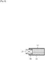
- a smokeless flavor inhalator according to a first embodiment, illustrated in FIG. 1is categorized as Carbon Combustion + High-temperature Gas Heating + Cooling type and is shaped like a rod as a whole.
- the inhalator of FIG. 1has a carbon heat source 10 at a distal end thereof.
- the carbon heat source 10will be described in detail.
- the carbon heat source 10is cylindrical in shape and is obtained by molding a mixture of high-purity carbon particles, an incombustible additive, an organic or inorganic binder, and water into shape. Specifically, the carbon heat source 10 has a carbon ratio of 10 to 99 weight % or a carbon content of 1 to 120 mg/mm.
- the high-purity carbon particlesare obtained, for example, by heating carbon at a high temperature of 750deg C or more for 5 minutes or more in an inert gas atmosphere. This heating process removes volatile components, which are impurities contained in carbon particles. As a result, odor emitted from the carbon particles is lessened.
- the incombustible additivecarbonates or oxides of sodium, potassium, calcium, magnesium and silicon may be used.
- the incombustible additiveaccounts for 40 to 89 weight % of the carbon heat source 10.
- calcium carbonateis used as the incombustible additive.
- the incombustible additiveis optional and may be omitted.
- the organic binderis one, or a mixture of two or more, of alginates, CMC, EVA, PVA, PVAC and sugars, and accounts for 1 to 10 weight % of the carbon heat source 10.
- a preferred organic binderis ammonium alginate.
- mineral-based binderssuch as refined bentonite, or silica-based binders, such as colloidal silica, water glass and calcium silicate, may be used.
- silica-based binderssuch as colloidal silica, water glass and calcium silicate.
- the inorganic binderaccounts for 5 to 20 weight % of the carbon heat source 10.
- the inorganic binderis superior to the organic binder in that the former emits no smoke when the carbon heat source 10 is burned.
- the carbon heat source 10is preferably obtained by a carbonizing-and-baking process.
- the carbonizing-and-baking processremoves the organic binder from the carbon heat source 10, and therefore, the carbon heat source 10 does not emit odor when burned.
- the carbonizing-and-baking processis described in detail in, for example, JP 3024703 B1 .
- the carbon heat source 10has at least one through hole 12 extending in an axial direction thereof.
- FIGS. 2 to 4each illustrate an exemplary concrete shape of an end face of the carbon heat source 1. As clearly shown in FIGS. 2 to 4 , adjacent ones of the through holes 12 are set apart from each other by a partition wall. In this case, the partition wall has a thickness of 0.1 to 0.5 mm.
- the carbon heat source 10is attached to a distal end of a heat source holder 14.
- the heat source holder 14will be described in detail.
- the heat source holder 14has heat resistance and is tubular in shape.
- the heat source holder 14holds the carbon heat source 10 in such a manner that a predetermined length of the carbon heat source 10 projects from the distal end of the heat source holder 14.
- the heat source holder 14has a peripheral wall with a laminated structure, for example.
- the peripheral wallis constituted by a single laminate including a metal layer and a paper layer bonded together, or by a plurality of such laminates superposed one upon the other in a radial direction of the heat source holder 14.
- An inner surface of the peripheral wallhas to be constituted by the metal layer.
- the metal layeris made of an aluminum alloy, for example, and the total thickness of the metal layers included in the peripheral wall is preferably larger than or equal to 30 µm.
- the paper layermay be obtained from wrapper paper used for cigarettes, tip paper used for filter-tipped cigarettes, or other paper material such as ordinary paper, incombustible paper and flame-resistant paper.
- the metal layerhas excellent heat conductivity. Accordingly, when the carbon heat source 10 is burned and thus the paper layer is heated by the heat from the carbon heat source 10, the metal layer keeps the heating temperature of the paper layer lower than the burning temperature of the paper layer. The emission of odor due to scorching of the paper layer can therefore be suppressed.
- the heat source holder 14may have a peripheral wall made of an incombustible material, or a composite peripheral wall including a wall section constituted by the aforementioned peripheral wall with the laminated structure and a wall section made of an incombustible material.
- the incombustible materialone of inorganic materials including ceramics, meerschaums, glass and metals or a mixture of two or more of the inorganic materials may be used.
- the heat source holder 14accommodates a cooling element 16.
- the cooling element 16has air permeability and heat resistance and is located adjacent to the carbon heat source 10. In the following, the cooling element 16 will be described in detail.
- the cooling element 16is made of an inorganic material such as ceramics, meerschaums, glass, metals and calcium carbonate, hydrates, or water absorptive polymers. Specifically, the cooling element 16 has a honeycomb structure, a foamed structure or a packing structure, the packing structure being obtained by packing pellets or a granular or fibrous material into a mold.
- the cooling element 16includes internal passages. These internal passages have a total inner surface or a heat exchange area of 500 mm 2 or more.
- the cooling element 16contains the inorganic material of 90 to 95 wt%.
- the cooling element 16may alternatively have a composite structure including two or more different structures selected from the above structures, and the different structures may be juxtaposed so as to be closely adjacent to each other or with a space therebetween in the axial direction of the heat source holder 14.
- the cooling element 16may contain water, an aromatic, an extraction liquid of tobacco components, and the like.
- a material holder 18is coupled to the proximal end of the heat source holder 14.
- the material holder 18has heat resistance and is tubular in shape.
- the material holder 18is made of paper, metal or synthetic resin, or is formed using the laminated structure of the aforementioned laminates.
- a tobacco material 20, as a flavor generator,is contained in the material holder 18.
- the tobacco material 20may be ordinary shredded tobacco used for cigarettes, granular tobacco used for snuff, rolled tobacco, or molded tobacco.
- the rolled tobaccois obtained by forming a sheet of reconstituted tobacco into a roll and has channels therein.
- the molded tobaccois obtained by molding granular tobacco into shape.
- the tobacco material 20may be admixed with a flavor-developing aid.
- the flavor-developing aidcontains at least one of carbonates, hydrogen carbonates, oxides and hydroxides of alkali metals and/or alkaline-earth metals.
- a preferred flavor-developing aidis potassium carbonate.
- the tobacco material 20may further contain a desired aromatic or aromatics.
- the tobacco material 20is 5 to 30 mm in length and has a resistance of 10 to 120 mmAq to draw. It is to be noted here that the tobacco material 20 has a water content equivalent to that of shredded tobacco used in ordinary cigarettes, that is, a water content of 10 to 20 weight %.
- the tobacco material 20is held between front and rear stoppers 22f and 22r to be kept within the material holder 18.
- Each of the stoppers 22f and 22ris shaped like a disk and has air permeability.
- the stoppers 22f and 22rare fitted into respective opposite ends of the material holder 18 and are each made of a filter material such as acetate and paper, or a membrane material such as nonwoven fabric, or formed using an inorganic molded piece having air permeability.
- a mouthpiece 24is connected to a rear end of the material holder 18.
- the mouthpiece 24includes a tubular filter holder 26.
- the filter holder 26is made of paper or a synthetic resin and has a rear end forming a mouthpiece.
- a filter 28is accommodated in the filter holder 26.
- the filter 28is in the form of a solid cylinder and is made of acetate fibers, paper or the like. Acetate fibers and paper have the property of not readily adsorbing the flavor components of the tobacco material 20.
- the filter 28may have at least one through hole axially extending therethrough. Further, the filter 28 may be a combination of different kinds of filter materials, like dual filters and the like for cigarettes.
- the userfirst lights the carbon heat source 10 of the flavor inhalator and then inhales with the mouthpiece 24 held in his/her mouth.
- the inhalationcreates a flow of air from the outside of the flavor inhalator into the user's mouth cavity through the through holes 12 of the carbon heat source 10, the cooling element 16 in the heat source holder 14, the front stopper 22f, the tobacco material 20, the rear stopper 22r, the filter 28 and the mouthpiece 24.
- the high-temperature gas flowis cooled in some degree while passing through the cooling element 16, thus turning to a heated gas flow.
- the heated gas flowheats the tobacco material 20 when passing through the tobacco material 20, but the heating of the tobacco material 20 by the heated gas flow does not lead to burning of the tobacco material 20 or generation of aerosol (smoke) from the tobacco material 20.
- the heating temperature of the tobacco material 20is kept within a temperature range of 50 to 200deg C. This temperature range is higher than an ambient temperature (concretely, 5 to 35deg C) at which the flavor inhalator is used, but is sufficiently lower than the heating temperature of the carbon heat source 10. Namely, the cooling element 16 has the function of lessening the amount of heat transferred from the carbon heat source 10 to the tobacco material 20.
- the heating temperature of the tobacco material 20is kept within the above temperature range, liquid contained in the tobacco material 20, such as water, is not aerosolized and the flavor components of the tobacco material 20 are satisfactorily released into the heated gas flow passing through the tobacco material 20.
- the aforementioned flavor-developing aidpromotes the release of the flavor components from the tobacco material 20 into the heated gas flow; on the other hand, the amount of the flavor components adsorbed by the filter 28 of the mouthpiece 24 is small.
- the flavor inhalatorallows the heated gas flow containing a large amount of the flavor components of the tobacco material 20 to be delivered into the user's mouth cavity without generating an aerosol, so that the user can fully enjoy the flavor of the tobacco material 20.
- the carbon heat source 10When the carbon heat source 10 is burned, the generation of smoke from the carbon heat source 10 is minimized as stated above, and therefore, the carbon heat source 10 also does not constitute a source of aerosol (smoke).
- smokelessused herein means that the aerosol generated from the flavor inhalator during use has a concentration of 1.0 X 10 5 particles/cc or less. Aerosol with such a concentration is substantially invisible and the concentration is virtually unmeasurable because of the influence of the background of ambient air.
- the water content of the tobacco material 20is equivalent to that of shredded tobacco contained in ordinary cigarettes. Accordingly, although the tobacco material 20 is heated to a temperature falling within the aforementioned temperature range and its water content varies as a result, the amount of the flavor components in the heated gas flow inhaled per puff of the user is almost constant. As a result, the user can enjoy the flavor of the tobacco material 20 reliably and stably even if he/she repeatedly puffs.
- the heat source holder 14, the material holder 18 and the filter holder 26constitute a casing of the flavor inhalator.
- these holders 14, 18 and 26 connected to one anotherat lease two of the holders may be formed as a one-piece body, or adjacent ones of the holders may be previously connected to each other by tip paper or the like. Further, the holders may be detachably connected to one another.
- FIG. 5illustrates modification 1(1) of the flavor inhalator of the first embodiment.
- a heat insulator 30is arranged between the carbon heat source 10 and the heat source holder 14.
- the heat insulator 30is tubular in shape and is made of an inorganic material such as inorganic fibers, or formed using an inorganic molded piece, for example.
- the heat insulator 30reduces the transfer of heat from the carbon heat source 10 to the heat source holder 14 and prevents the generation of smoke due to scorching of the heat source holder 14. Also, the heat insulator 30 may be so arranged as to surround the entire outer periphery of the carbon heat source 10. In this case, smoke, if produced in a small amount due to the combustion of the carbon heat source 10, is dispersed within the heat insulator 30 and does not become visible.
- FIG. 6illustrates modification 1(2) of the smokeless flavor inhalator of the first embodiment.
- the flavor inhalatorhas a plurality of air inlet holes 32 formed in at least one of the heat source holder 14, the material holder 18 and the filter holder 26.
- the air inlet holes 32are located downstream of the carbon heat source 10 and are arranged at intervals in the circumferential direction of the corresponding holder.
- the air inlet holes 32are formed in each of the heat source holder 14, the material holder 18 and the filter holder 26.
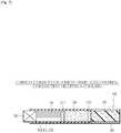
- FIG. 7illustrates a smokeless flavor inhalator according to a second embodiment.
- the flavor inhalator of FIG. 7is categorized as Carbon Combustion + High-temperature Gas/Thermal Conduction Heating + Cooling type.
- the flavor inhalator of the second embodimentis provided with a heat conduction holder 50.
- the heat conduction holder 50not only serves as both of the heat source holder 14 and the material holder 18 but has the function of transferring the heat of the carbon heat source 10 to the tobacco material 20. Accordingly, the heat conduction holder 50 is made of a highly heat-conductive material.
- the heat conduction holder 50allows heat to be transferred from the carbon heat source 10 to the tobacco material 20.
- the tobacco material 20is continuously heated to emit the flavor components having a rich taste and aroma.
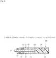
- FIG. 8illustrates a smokeless flavor inhalator according to an example, which is not part of the present invention.
- This flavor inhalatoris categorized as Carbon Combustion + Thermal Conduction Heating type.
- the flavor inhalator of the exampleis also provided with the heat conduction holder 50 but uses an incombustible element 52, in place of the cooling element 16 and the front stopper 22f.
- the incombustible element 52has air impermeability and heat resistance. Specifically, the incombustible element 52 is constituted by a filler of inorganic fibers or an inorganic molded piece and, as clearly shown in FIG. 8 , is interposed between the carbon heat source 10 and the tobacco material 20 within the heat conduction holder 50.
- the heat conduction holder 50Since the incombustible element 52 is impermeable to air, the heat conduction holder 50 has a plurality of air inlet holes 32 formed in the outer periphery thereof.
- heat generated by the combustion of the carbon heat source 10is transferred to the tobacco material 20 only through the heat conduction holder 50, and the tobacco material 20 is heated to a temperature within the aforementioned temperature range only by the thus-transferred heat. That is, the heat conduction holder 50 performs a function similar to that of the aforementioned cooling element 16. In this case, it is unlikely that the user will inhale the combustion gas produced by the combustion of the carbon heat source 10.
- the carbon heat source 10need not have air permeability.
- the incombustible element 52may have air permeability.
- either the carbon heat source 10 or the incombustible element 52has only to be impermeable to air, in order to prevent the combustion gas from flowing into the tobacco material 20.
- the carbon heat source 10preferably has a circular cross section, as illustrated in FIG. 2 or 3 .
- the carbon heat source 10 illustrated in FIG. 2 or 3has a large effective heat transfer area with respect to the inner peripheral surface of the heat conduction holder 50, compared with the carbon heat source 10 shown in FIG. 4 .
- FIG. 9illustrates modification 3(1) of the flavor inhalator of fig. 8 , which is not part of the present invention.
- the flavor inhalatoris provided with a heat conduction rod 54, in place of the heat conduction holder 50.
- the heat conduction rod 54extends through the carbon heat source 10, the incombustible element 52 and the tobacco material 20 in their center and has an outer end projecting from the carbon heat source 10 and an inner end disposed in contact with the rear stopper 22r.
- the carbon heat source 10 the incombustible element 52 and the tobacco material section 20are each tubular or annular in shape.
- the heat conduction rod 54is made of a metal having high heat conductivity, for example, an aluminum alloy, and is a solid member or a hollow member with at least one end closed. Compared with the solid heat conduction rod, the hollow heat conduction rod 54 has small heat capacity and thus is capable of satisfactorily and quickly conducting heat from the carbon heat source 10 to the tobacco material 20.
- the heat conduction rod 54may, in this case, have an outer diameter of 1 to 5 mm, and the length of the tobacco material section 20 may be 5 to 50 mm.
- FIG. 10illustrates modification 3(2) of the flavor inhalator of fig. 8 , which is not part of the present invention.
- a heat conduction pipe 56is arranged inside the hollow carbon heat source 10 coaxially therewith.
- the heat conduction pipe 56serves as both of the material holder 18 and the heat conduction rod 54.
- the heat conduction pipe 56has an air inlet opening located at a distal end face of the carbon heat source 10, and the front stopper 22f is fitted into the distal end portion of the heat conduction pipe 56.
- a gap of 5 mm or moreis provided between the front stopper 22f and the air inlet opening. The gap serves to reliably prevent the tobacco material 20 from burning when the carbon heat source 10 is lighted.
- the carbon heat source 10is surrounded by an outer heat insulator 58.
- the outer heat insulator 58is in the form of a thin pipe and has air permeability, that is, breathability.
- the outer heat insulator 58serves to reduce the radiation of heat from the carbon heat source 10, thereby making it possible to keep the amount of heat necessary for sustaining the combustion of the carbon heat source 10, and thus is very effective in securing combustion sustention of the carbon heat source 10.
- an insulator in the form of a thin pipe(not shown) is arranged between the carbon heat source 10 and the heat conduction pipe 56, and/or between the heat conduction pipe 56 and the tobacco material 20.
- the heat conduction pipe 56has an outer diameter of 3 to 8 mm and an inner diameter of 2 to 7 mm.
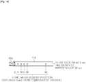
- FIG. 11illustrates a smokeless flavor inhalator according to another example, which is not part of the present invention.
- This flavor inhalatoris categorized as Carbon Combustion + Air Heating type.
- the carbon heat source 10has an air inlet hole 60 formed in the center thereof.
- the air inlet hole 60axially penetrates through the carbon heat source 10.
- the carbon heat source 10has a heat-resistant coating 62 covering the entire inner surface of the air inlet hole 60.
- the heat-resistant coating 62may be made of clay, or a metal oxide such as iron oxide, alumina, titania, silica, silica-alumina, zirconia and zeolite, or a mixture of clay and two or more of the mentioned metal oxides.
- the incombustible element 52has a through hole 64 formed in the center thereof and connected to the air inlet hole 60.
- the incombustible element 52has an extension surrounding the rear end portion of the carbon heat source 10.
- the incombustible element 52serves also as the heat source holder 14.
- the reference sign L 1represents a projection length of the carbon heat source 10 projecting from the incombustible element 52
- the reference sign L 2represents an overlap length (length of the extension) of the incombustible element 52 overlapping with the carbon heat source 10.
- the flavor inhalator of the last examplewhen the user inhales through the mouthpiece 24 after lighting the carbon heat source 10, air flows into the tobacco material 20 through the air inlet hole 60 of the carbon heat source 10 and the through hole 64 of the incombustible element 52, and the air is heated to a temperature within the aforementioned temperature range in the process of passing through the carbon heat source 10.
- the flavor inhalator of this last examplealso permits the flavor components of the tobacco material 20 to be adequately delivered into the user's mouth cavity without generating an aerosol.
- the smokeless flavor inhalator of the present inventionrequires that the tobacco material 20 be heated to a temperature of 50deg C to 200deg C while the inhalator is in use.
- a first testing device shown in FIG. 12was prepared.
- the first testing deviceis provided with a heat resistant tube 100 accommodating the tobacco material 20, and a heater 102 surrounding the tube 100 and capable of heating the tube 100, namely, the tobacco material 20, up to 22deg C or 50deg C.
- the tobacco material 20 subjected to the testcontained 230 mg of tobacco particles made from Burley tobacco leaves and 14 mg of potassium carbonate. The tobacco particles had a particle diameter of 0.5 to 1.18 mm.
- the first testing deviceis further provided with a suction source 104, which is connected to the tube 100 through an impinger 106.
- the suction source 104is configured to draw in air or a gas from the tube 100 through the impinger 106 at a flow rate of 55 ml/2 sec (corresponding to one puff).
- the suction gaswas drawn to the suction source 104 while being allowed to bubble in the impinger 106 so that a flavor component (nicotine) of the tobacco material contained in the suction gas might be collected in the impinger 106.
- a flavor component(nicotine) of the tobacco material contained in the suction gas might be collected in the impinger 106.
- the amount of the collected flavor componentwas 0.7 µg/puff.
- the flavor componentwas collected in the impinger 106 in the same manner, and it was found that the amount of the collected flavor component was 9.0 µg/puff.
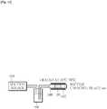
- FIG. 13illustrates a second testing device.
- the second testing deviceis provided with a heat resistant tube 108 accommodating the tobacco material 20.
- the tobacco material 20 subjected to the testcontained 35 mg of tobacco particles made from Burley tobacco leaves, and the tobacco particles had a particle diameter of 0.5 to 1.18 mm.
- the tube 108is connected through a transparent case 110 and a mass-flow controller 112 to a suction pump 114, which is capable of drawing in air from the tube 108 at a flow rate of 1,650 ml/min.
- the cooling element 16needs to have the heat exchange area of 500 mm 2 , as stated above.
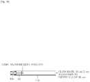
- a third testing device illustrated in FIG. 14was prepared.
- the third testing deviceis provided with a tube 116 made of heat resistant paper.
- the tube 116has a hollow cylindrical carbon heat source 10a attached to a distal end thereof.
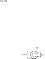
- the carbon heat source 10a subjected to the testwas obtained by extrusion molding and contained 80 weight % of active carbon, 15 weight % of calcium carbonate, and 5 weight % of carboxymethylcellulose (CMC). Specifically, as illustrated in FIGS. 15 and 16 , the carbon heat source 10a had an inner diameter of 3 mm, an outer diameter of 6.8 mm, and a length of 10 mm.
- the proximal end of the tube 116is connected to a suction source (not shown), and the suction source is configured to draw in air from the tube 116 at a flow rate of 55 ml/2 sec (corresponding to one puff) at intervals of 30 seconds.
- the tube 116has five temperature sensors (not shown) attached thereto. The temperature sensors are located at distances of 5 mm, 10 mm, 15 mm, 20 mm and 50 mm from the carbon heat source 10a, respectively, and are each capable of measuring the temperature in the tube 116.
- the temperature in the tube 116shows a tendency to lower with increasing distance from the carbon heat source 10a, and in order for the temperature in the tube 116 to drop to 200deg C or less, a distance of 50 mm or more from the carbon heat source 10a is needed.
- a distance of 50 mm or moreneeds to be secured between the carbon heat source 10a and the tobacco material 20 in order to restrict the heating temperature of the tobacco material 20 to a temperature not higher than 200deg C, at and below which generation of smoke (aerosol) from the tobacco material 20 can be avoided.
- the smokeless flavor inhalatordoes not include the cooling element 16
- a distance of 50 mm or moreneeds to be provided between the carbon heat source 10a and the tobacco material 20.
- Such a flavor inhalatoris, however, extraordinarily long and is not practical.
- FIG. 18illustrates a fourth testing device prepared for verifying the function of the cooling element 16.
- the fourth testing deviceincludes the cooling element 16 having air permeability as well as heat resistance and arranged inside the tube 116 in a position adjacent to the carbon heat source 10a.
- the temperature sensoris arranged only at the outlet end (downstream end) of the cooling element 16 to measure the temperature in the tube 116 at the outlet of the cooling element 16.
- cooling elements 16a and 16bFor use with the fourth testing device, multiple pieces of cylindrical cooling elements 16a and 16b, illustrated in FIGS. 19 and 20 , respectively, were prepared.
- the cooling elements 16a and 16bwere each obtained by extrusion molding and contained 95 weight % of calcium carbonate and 5 weight % of carboxymethylcellulose (CMC).
- the cooling elements 16a and 16bare identical in outer diameter (6.5 mm) but are different in the opening area of their internal passages. Specifically, the cooling element 16a had an opening area of 17.2 mm 2 obtained, for example, by 52 through holes each with a square (0.57 mm X 0.57 mm) cross-section. In this case, the total length of the inner perimeters of all through holes is 120 mm.
- the cooling element 16bhad an opening area of 24.1 mm 2 obtained, for example, by 21 through holes each with a square (1.23 mm X 1.23 mm) cross-section. In this case, the total length of the inner perimeters of all through holes is 90.9 mm.
- the cooling elements 16a and 16bSince the heat exchange areas of the cooling elements 16a and 16b are each given by: inner perimeter X length, the cooling elements 16a and 16b with different lengths were prepared.
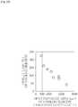
- FIGS. 21 and 22show the test results. As is clear from FIG. 21 , the greater the length, the lower the outlet temperature of the cooling element 16 becomes, regardless of whether the cooling element tested is the cooling element 16a or the cooling element 16b.
- the test resultsindicate that a heat exchange area of 500 mm 2 is needed in order to keep the outlet temperature of the cooling element 16, that is, the heating temperature of the tobacco material 20, at 200deg C or below.
- the cooling element 16a or 16bin the smokeless flavor inhalator, it is possible to significantly shorten the distance (length of the cooling element 16a or 16b) needed between the carbon heat source 10 and the tobacco material 20, so that the overall length of the smokeless flavor inhalator can be reduced to a practical level.
- the cooling element 16a or 16b located between the carbon heat source 10 and the tobacco material 20need not be disposed in direct contact with the carbon heat source 10 or the tobacco material 20.
- a predetermined spacemay be provided between the carbon heat source 10 and the cooling element 16a or 16b, or between the cooling element 16a or 16b and the tobacco material 20.
- the presence of the cooling element 16a or 16bmakes it unnecessary to introduce outside air to the upstream side of the tobacco material 20, that is, into the region between the carbon heat source 10 and the tobacco material 20, in order to keep the heating temperature of the tobacco material 20 at a temperature not higher than 200deg C, and also prevents the ignition performance of the carbon heat source 10 from being deteriorated due to the inflow of the outside air.
- the introduction of outside airleads to reduction in the amount of the outside air passing through the carbon heat source 10 when the carbon heat source 10 is lighted, deteriorating the ignition performance of the carbon heat source 10.
- the flavor generatoris not limited to the aforementioned tobacco material and may be a liquid or solid aromatic, other than the flavor components of the tobacco material, carried on a base material of cellulose or the like.
- the flavor inhalator of the present inventionmay be implemented by optionally combining the elements in the aforementioned embodiments and modifications with commonly known means without departing from the scope of the appended claims.
Landscapes
- Cigarettes, Filters, And Manufacturing Of Filters (AREA)
- Manufacture Of Tobacco Products (AREA)
Description
- The present invention relates to smokeless flavor inhalators capable of releasing flavor without generating aerosol to allow users to inhale and enjoy the released flavor.
- Smoking articles such as cigarettes and cigars are typical flavor generation products using, as a medium, the smoke (aerosol) produced by the combustion of tobacco leaves to allow users to enjoy the flavor of tobacco through the senses of taste and smell.
- Meanwhile, in recent years, there have been known a variety of substitutes for the smoking articles that allow the user to enjoy the flavor of tobacco. The substitutes for the smoking articles can be roughly classified into two types, non-heating type and heating type. In either type, tobacco leaves are not burned, and thus it is possible to prevent the sidestream smoke or smell of the burned tobacco leaves from affecting the people around the user.
- For example, the non-heating type smoking article substitute disclosed in Patent Document 1 identified below includes a holder provided with an air inlet opening and a mouthpiece, and an air permeable vessel accommodated in the holder. The air permeable vessel is filled with a tobacco material impregnated with the flavor components of tobacco.
- With the smoking article substitute of Patent Document 1, the user has only to inhale, through the mouthpiece, the air that has passed through the tobacco material, without lighting the tobacco material, to enjoy the flavor of tobacco contained in the air.
- The heating-type substitutes for the smoking articles, on the other hand, can be classified in more detail according to the type of heat source and the method of transferring heat from the heat source to the tobacco material or the flavor generator.
- Specifically, the smoking article substitutes disclosed in
Patent Documents 2 to 6 use a carbon heat source. The carbon heat source heats air by utilizing the heat of combustion thereof, to produce a high-temperature gas flow for heating the tobacco material or the flavor generator. In the heating-type smoking article substitutes, the flavor components of tobacco are vaporized and released invariably by heating the tobacco material or the flavor generator. - The smoking article substitutes disclosed in Patent Documents 7 and 8 also use a carbon heat source. In these substitutes, heat generated by the combustion of the carbon heat source is transferred to the tobacco material or the flavor generator to heat same.
- The smoking article substitutes disclosed in Patent Documents 9 to 13 use a liquid or gas fuel as the heat source.
- Specifically, in the smoking article substitute of Patent Document 9, a liquid fuel is burned with the aid of a catalyst, and the tobacco material or the flavor generator is heated by a high-temperature gas flow created by the combustion heat of the liquid fuel.
- The smoking article substitute of
Patent Document 10 is equipped with a micro gas burner as an attachment, which is used to heat a cigarette. - In the smoking article substitutes of
Patent Documents 10 to 12, butane gas is burned with the aid of a catalyst, and heat generated by the combustion of the gas is transferred to the tobacco material or the flavor generator to heat same. - The smoking article substitute of Patent Document 13 is provided with a heat sink, which stores heat therein as it is heated by the flame of a gas lighter (external heat source). The heat stored in the heat sink is transferred through a heat pipe to a volatile component (flavor generator) to heat same.
- The smoking article substitutes disclosed in
Patent Documents 14 to 17 are provided with a heat source utilizing the heat of chemical reaction. Specifically, in the smoking article substitutes ofPatent Documents Patent Documents 16 and 17, the heat source generates heat by utilizing the heat of oxidation reaction of metal, to heat the tobacco material or the flavor generator. - The smoking article substitutes disclosed in
Patent Documents 18 to 21 are all provided with a heat source utilizing electrical energy. Namely, the heat source converts electrical energy to heat energy, which is used to heat the tobacco material or the flavor generator. - With regard to the smoking article substitute disclosed in Patent Document 22, additives to be added to the tobacco material and heating conditions for heating the additives are defined with a view to heightening the flavor component releasing effect.
EP 1 468 618 A1 discloses a smokeless flavor inhalator comprising the features of the preamble of claim 1. - Patent Document 1:
JP H02-2331 A1 - Patent Document 2:
JP S63-35468 A1 - Patent Document 3:
JP H06-46818 A1 - Patent Document 4:
JP H03-45658 B1 - Patent Document 5:
JP 3012253 B1 - Patent Document 6:
JP H02-84164 A1 - Patent Document 7:
JP 3013914 B1 - Patent Document 8:
WO 2009/22232 - Patent Document 9:
WO 2008/113420 - Patent Document 10:
JP 2006-504065 A1 - Patent Document 11:
WO 2007/12007 - Patent Document 12:
WO 2009/79641 - Patent Document 13:
JP 2008-35742 A1 - Patent Document 14:
US 4892109 B1 - Patent Document 15:
JP H02-190171 A1 - Patent Document 16:
JP H06-114105 A1 - Patent Document 17:
WO 2009/92862 - Patent Document 18:
US 5144962 B1 - Patent Document 19:
US 5060671 B1 - Patent Document 20:
WO 2004/80216 - Patent Document 21:
JP 2006-525798 A1 - Patent Document 22:
JP S62-501050 A1 - In the case of the smoking article substitute of Patent Document 1, no smoke is produced from the tobacco material, but the amount of the flavor components released from the tobacco material is small, so that the user will not be completely satisfied with the flavor derived from the tobacco material.
- In this connection, in the smoking article substitutes of
Patent Documents 2 to 21, the tobacco material or the flavor generator is heated, thus allowing a large amount of flavor components to be released from the tobacco material or the flavor generator, compared with the smoking article substitute of Patent Document 1. It is therefore thought that the user will be able to enjoy the flavor to an extent equivalent to that to which the user senses when smoking an ordinary filter cigarette. Since the heating of the tobacco material or the flavor generator is accompanied by the generation of aerosol, however, the smoking article substitutes ofPatent Documents 2 to 21 are not perfectly smokeless. - On the other hand, the smoking article substitute of Patent Document 22 is smokeless and at the same time is capable of releasing an increased amount of flavor components. In the case of the smoking article substitute of Patent Document 22, however, it is necessary that a large amount of water should be contained in the tobacco material. Specifically, the water content needs to be 0.25 to 7 g, preferably, 1 to 5 g per gram of the tobacco material.
- In the case of ordinary filter cigarettes, the water content per gram of the tobacco material is 0.1 to 0.15 g, and even in snuff having a relatively high water content such as snus, the upper-limit water content per gram of the tobacco material is 0.5 g or thereabout from the standpoint of preservative quality. In view of this, the smoking article substitute of Patent Document 22 is not suitable for commercial realization from the standpoint of the preservative quality of the tobacco material.
- Aside from the preservative quality, the water content of the tobacco material decreases due to the heating of the tobacco material. Thus, as the user repeatedly inhales, the amount of the flavor components released from the tobacco material varies, which brings a feeling of strangeness to the user.
- An object of the present invention is to provide a smokeless flavor inhalator permitting compatibility between smokelessness and strengthening of flavor and also capable of stabilizing the amount of flavor components released each time the user inhales through the flavor inhalator.
- To achieve the above object, the present invention provides a smokeless flavor inhalator comprising the features of claim 1.
- In the above smokeless flavor inhalator, the heater keeps the heating temperature of the flavor generator at a temperature of 50 to 200deg C. Accordingly, when the user inhales through the flavor inhalator, the flavor generator releases the flavor component into the air flow guided toward the mouthpiece, without generating any aerosol (smoke). The flavor inhalator is therefore not only smokeless but is capable of delivering the flavor component into the user's mouth.
- The cooling element has a plurality of through holes formed therethrough, and the through holes provide the cooling element with a heat exchange area of 500 mm2 or more. The presence of the cooling element serves to shorten the distance required between the carbon heat source and the flavor generator, making it possible to reduce the length of the flavor inhalator.
- More detailed and preferred constructions of the present invention will become apparent from the following description of the embodiments and modifications taken in conjunction with the accompanying drawings.
- The smokeless flavor inhalator of the present invention permits flavor components to be effectively released from the flavor generator without an aerosol being generated from the flavor generator, whereby the flavor components of the flavor generator can be adequately delivered into the user's mouth.
- [
fig.1]FIG. 1 is a longitudinal sectional view of a smokeless flavor inhalator according to a first embodiment. - [
fig.2]FIG. 2 exemplifies an end face of a carbon heat source. - [
fig.3]FIG. 3 exemplifies another end face of the carbon heat source. - [
fig.4]FIG. 4 exemplifies still another end face of the carbon heat source. - [
fig.5]FIG. 5 is a longitudinal sectional view of a heat source holder according to modification 1(1) of the first embodiment. - [
fig.6]FIG. 6 is a longitudinal sectional view of a flavor inhalator according to modification 1(2) of the first embodiment. - [
fig.7]FIG. 7 is a longitudinal sectional view of a smokeless flavor inhalator according to a second embodiment. - [
fig.8]FIG. 8 is a longitudinal sectional view of a smokeless flavor inhalator according to an example, which is not part of the present invention. - [
fig.9]FIG. 9 is a longitudinal sectional view of a flavor inhalator according to modification 3(1) of the example offig. 8 , which is not part of the present invention. - [
fig.10]FIG. 10 is a longitudinal sectional view of a flavor inhalator according to modification 3(2) of the example offig. 8 , which is not part of the present invention. - [
fig. 11]FIG. 11 is a longitudinal sectional view of a smokeless flavor inhalator according to another example, which is not part of the present invention. - [
fig. 12] FIG. 12 schematically illustrates a first testing device. - [
fig.13]FIG. 13 schematically illustrates a second testing device. - [
fig.14]FIG. 14 schematically illustrates a third testing device. - [
fig.15]FIG. 15 is an end view of a carbon heat source used in the third testing device. - [
fig.16]FIG. 16 is a perspective view of the carbon heat source ofFIG. 15 . - [
fig.17]FIG. 17 is a graph showing test results obtained using the third testing device. - [
fig.18]FIG. 18 schematically illustrates a fourth testing device. - [
fig.19]FIG. 19 is an end view of a cooling element used in the fourth testing device. - [
fig.20]FIG. 20 is an end view of another cooling element used in the fourth testing device. - [
fig.21]FIG. 21 is a graph showing test results obtained using the fourth testing device. - [
fig.22]FIG. 22 is a graph showing the relations between heat exchange areas and outlet temperatures of the cooling element. - A smokeless flavor inhalator according to a first embodiment, illustrated in
FIG. 1 , is categorized as Carbon Combustion + High-temperature Gas Heating + Cooling type and is shaped like a rod as a whole. - The inhalator of
FIG. 1 has acarbon heat source 10 at a distal end thereof. In the following, thecarbon heat source 10 will be described in detail. - The
carbon heat source 10 is cylindrical in shape and is obtained by molding a mixture of high-purity carbon particles, an incombustible additive, an organic or inorganic binder, and water into shape. Specifically, thecarbon heat source 10 has a carbon ratio of 10 to 99 weight % or a carbon content of 1 to 120 mg/mm. - The high-purity carbon particles are obtained, for example, by heating carbon at a high temperature of 750deg C or more for 5 minutes or more in an inert gas atmosphere. This heating process removes volatile components, which are impurities contained in carbon particles. As a result, odor emitted from the carbon particles is lessened.
- For the incombustible additive, carbonates or oxides of sodium, potassium, calcium, magnesium and silicon may be used. The incombustible additive accounts for 40 to 89 weight % of the
carbon heat source 10. Preferably, calcium carbonate is used as the incombustible additive. The incombustible additive is optional and may be omitted. - The organic binder is one, or a mixture of two or more, of alginates, CMC, EVA, PVA, PVAC and sugars, and accounts for 1 to 10 weight % of the
carbon heat source 10. A preferred organic binder is ammonium alginate. - For the inorganic binder, on the other hand, mineral-based binders, such as refined bentonite, or silica-based binders, such as colloidal silica, water glass and calcium silicate, may be used. The inorganic binder accounts for 5 to 20 weight % of the
carbon heat source 10. - The inorganic binder is superior to the organic binder in that the former emits no smoke when the
carbon heat source 10 is burned. Where the organic binder is used, thecarbon heat source 10 is preferably obtained by a carbonizing-and-baking process. The carbonizing-and-baking process removes the organic binder from thecarbon heat source 10, and therefore, thecarbon heat source 10 does not emit odor when burned. The carbonizing-and-baking process is described in detail in, for example,JP 3024703 B1 - The
carbon heat source 10 has at least one throughhole 12 extending in an axial direction thereof.FIGS. 2 to 4 each illustrate an exemplary concrete shape of an end face of the carbon heat source 1. As clearly shown inFIGS. 2 to 4 , adjacent ones of the throughholes 12 are set apart from each other by a partition wall. In this case, the partition wall has a thickness of 0.1 to 0.5 mm. - The
carbon heat source 10 is attached to a distal end of aheat source holder 14. In the following, theheat source holder 14 will be described in detail. - The
heat source holder 14 has heat resistance and is tubular in shape. Preferably, theheat source holder 14 holds thecarbon heat source 10 in such a manner that a predetermined length of thecarbon heat source 10 projects from the distal end of theheat source holder 14. - The
heat source holder 14 has a peripheral wall with a laminated structure, for example. Specifically, the peripheral wall is constituted by a single laminate including a metal layer and a paper layer bonded together, or by a plurality of such laminates superposed one upon the other in a radial direction of theheat source holder 14. An inner surface of the peripheral wall has to be constituted by the metal layer. The metal layer is made of an aluminum alloy, for example, and the total thickness of the metal layers included in the peripheral wall is preferably larger than or equal to 30 µm. The paper layer may be obtained from wrapper paper used for cigarettes, tip paper used for filter-tipped cigarettes, or other paper material such as ordinary paper, incombustible paper and flame-resistant paper. - The metal layer has excellent heat conductivity. Accordingly, when the
carbon heat source 10 is burned and thus the paper layer is heated by the heat from thecarbon heat source 10, the metal layer keeps the heating temperature of the paper layer lower than the burning temperature of the paper layer. The emission of odor due to scorching of the paper layer can therefore be suppressed. - Instead of the peripheral wall with the aforementioned laminated structure, the
heat source holder 14 may have a peripheral wall made of an incombustible material, or a composite peripheral wall including a wall section constituted by the aforementioned peripheral wall with the laminated structure and a wall section made of an incombustible material. For the incombustible material, one of inorganic materials including ceramics, meerschaums, glass and metals or a mixture of two or more of the inorganic materials may be used. - The
heat source holder 14 accommodates acooling element 16. Thecooling element 16 has air permeability and heat resistance and is located adjacent to thecarbon heat source 10. In the following, thecooling element 16 will be described in detail. - The
cooling element 16 is made of an inorganic material such as ceramics, meerschaums, glass, metals and calcium carbonate, hydrates, or water absorptive polymers. Specifically, thecooling element 16 has a honeycomb structure, a foamed structure or a packing structure, the packing structure being obtained by packing pellets or a granular or fibrous material into a mold. Thecooling element 16 includes internal passages. These internal passages have a total inner surface or a heat exchange area of 500 mm2 or more. Preferably, thecooling element 16 contains the inorganic material of 90 to 95 wt%. - The
cooling element 16 may alternatively have a composite structure including two or more different structures selected from the above structures, and the different structures may be juxtaposed so as to be closely adjacent to each other or with a space therebetween in the axial direction of theheat source holder 14. Thecooling element 16 may contain water, an aromatic, an extraction liquid of tobacco components, and the like. - A
material holder 18 is coupled to the proximal end of theheat source holder 14. Thematerial holder 18 has heat resistance and is tubular in shape. Thematerial holder 18 is made of paper, metal or synthetic resin, or is formed using the laminated structure of the aforementioned laminates. - A
tobacco material 20, as a flavor generator, is contained in thematerial holder 18. Thetobacco material 20 may be ordinary shredded tobacco used for cigarettes, granular tobacco used for snuff, rolled tobacco, or molded tobacco. The rolled tobacco is obtained by forming a sheet of reconstituted tobacco into a roll and has channels therein. The molded tobacco is obtained by molding granular tobacco into shape. - The
tobacco material 20 may be admixed with a flavor-developing aid. The flavor-developing aid contains at least one of carbonates, hydrogen carbonates, oxides and hydroxides of alkali metals and/or alkaline-earth metals. A preferred flavor-developing aid is potassium carbonate. Thetobacco material 20 may further contain a desired aromatic or aromatics. - Specifically, the
tobacco material 20 is 5 to 30 mm in length and has a resistance of 10 to 120 mmAq to draw. It is to be noted here that thetobacco material 20 has a water content equivalent to that of shredded tobacco used in ordinary cigarettes, that is, a water content of 10 to 20 weight %. - In this embodiment, the
tobacco material 20 is held between front andrear stoppers material holder 18. Each of thestoppers stoppers material holder 18 and are each made of a filter material such as acetate and paper, or a membrane material such as nonwoven fabric, or formed using an inorganic molded piece having air permeability. - A
mouthpiece 24 is connected to a rear end of thematerial holder 18. Themouthpiece 24 includes atubular filter holder 26. Thefilter holder 26 is made of paper or a synthetic resin and has a rear end forming a mouthpiece. - A
filter 28 is accommodated in thefilter holder 26. Thefilter 28 is in the form of a solid cylinder and is made of acetate fibers, paper or the like. Acetate fibers and paper have the property of not readily adsorbing the flavor components of thetobacco material 20. Thefilter 28 may have at least one through hole axially extending therethrough. Further, thefilter 28 may be a combination of different kinds of filter materials, like dual filters and the like for cigarettes. - To use the flavor inhalator of the first embodiment, the user first lights the
carbon heat source 10 of the flavor inhalator and then inhales with themouthpiece 24 held in his/her mouth. The inhalation creates a flow of air from the outside of the flavor inhalator into the user's mouth cavity through the throughholes 12 of thecarbon heat source 10, thecooling element 16 in theheat source holder 14, thefront stopper 22f, thetobacco material 20, therear stopper 22r, thefilter 28 and themouthpiece 24. - While passing through the through
holes 12 in thecarbon heat source 10, the air flow is heated by the combustion heat of thecarbon heat source 10. Accordingly, the air flow just left thecarbon heat source 10 forms a high-temperature gas flow. - The high-temperature gas flow is cooled in some degree while passing through the
cooling element 16, thus turning to a heated gas flow. The heated gas flow heats thetobacco material 20 when passing through thetobacco material 20, but the heating of thetobacco material 20 by the heated gas flow does not lead to burning of thetobacco material 20 or generation of aerosol (smoke) from thetobacco material 20. - The heating temperature of the
tobacco material 20 is kept within a temperature range of 50 to 200deg C. This temperature range is higher than an ambient temperature (concretely, 5 to 35deg C) at which the flavor inhalator is used, but is sufficiently lower than the heating temperature of thecarbon heat source 10. Namely, thecooling element 16 has the function of lessening the amount of heat transferred from thecarbon heat source 10 to thetobacco material 20. - Where the heating temperature of the
tobacco material 20 is kept within the above temperature range, liquid contained in thetobacco material 20, such as water, is not aerosolized and the flavor components of thetobacco material 20 are satisfactorily released into the heated gas flow passing through thetobacco material 20. Moreover, the aforementioned flavor-developing aid promotes the release of the flavor components from thetobacco material 20 into the heated gas flow; on the other hand, the amount of the flavor components adsorbed by thefilter 28 of themouthpiece 24 is small. - Consequently, the flavor inhalator allows the heated gas flow containing a large amount of the flavor components of the
tobacco material 20 to be delivered into the user's mouth cavity without generating an aerosol, so that the user can fully enjoy the flavor of thetobacco material 20. - When the
carbon heat source 10 is burned, the generation of smoke from thecarbon heat source 10 is minimized as stated above, and therefore, thecarbon heat source 10 also does not constitute a source of aerosol (smoke). - The term "smokeless" used herein means that the aerosol generated from the flavor inhalator during use has a concentration of 1.0 X 10⁵ particles/cc or less. Aerosol with such a concentration is substantially invisible and the concentration is virtually unmeasurable because of the influence of the background of ambient air.
- The water content of the
tobacco material 20 is equivalent to that of shredded tobacco contained in ordinary cigarettes. Accordingly, although thetobacco material 20 is heated to a temperature falling within the aforementioned temperature range and its water content varies as a result, the amount of the flavor components in the heated gas flow inhaled per puff of the user is almost constant. As a result, the user can enjoy the flavor of thetobacco material 20 reliably and stably even if he/she repeatedly puffs. - Where an aromatic or aromatics different from the tobacco-specific flavor components are contained in the
tobacco material 20, the user can of course enjoy the aromatic or aromatics at the same time. - In the first embodiment described above, the
heat source holder 14, thematerial holder 18 and thefilter holder 26 constitute a casing of the flavor inhalator. Of theseholders - The present invention is not limited to the aforementioned first embodiment and may be modified in various ways, within the scope of the appended claims.
- In the following, various modifications and other embodiments will be described in order. In the following description, identical reference signs are used to denote members or sections having functions identical with those of the members or sections already explained above, and description of such members and sections is omitted for brevity's sake. The following description is focused on the differences.
FIG. 5 illustrates modification 1(1) of the flavor inhalator of the first embodiment. In modification 1(1), as is clear fromFIG. 5 , aheat insulator 30 is arranged between thecarbon heat source 10 and theheat source holder 14. Theheat insulator 30 is tubular in shape and is made of an inorganic material such as inorganic fibers, or formed using an inorganic molded piece, for example.- The
heat insulator 30 reduces the transfer of heat from thecarbon heat source 10 to theheat source holder 14 and prevents the generation of smoke due to scorching of theheat source holder 14. Also, theheat insulator 30 may be so arranged as to surround the entire outer periphery of thecarbon heat source 10. In this case, smoke, if produced in a small amount due to the combustion of thecarbon heat source 10, is dispersed within theheat insulator 30 and does not become visible. FIG. 6 illustrates modification 1(2) of the smokeless flavor inhalator of the first embodiment.- In modification 1(2), the flavor inhalator has a plurality of air inlet holes 32 formed in at least one of the
heat source holder 14, thematerial holder 18 and thefilter holder 26. The air inlet holes 32 are located downstream of thecarbon heat source 10 and are arranged at intervals in the circumferential direction of the corresponding holder. Specifically, in modification 1(2) illustrated inFIG. 6 , the air inlet holes 32 are formed in each of theheat source holder 14, thematerial holder 18 and thefilter holder 26. - When the user inhales through the
mouthpiece 24 of the flavor inhalator ofFIG. 6 , outside air flows into the corresponding holder through the air inlet holes 32. This inflow of air reduces the flow rate of the aforementioned high-temperature gas flow or heated gas flow, and the air thus introduced mixes with the high-temperature gas flow or the heated gas flow, lowering the temperature of the high-temperature gas flow or the heated gas flow. That is, the air introduced through the air inlet holes 32 adds to the cooling function of thecooling element 16 and is very effective in keeping the heating temperature of thetobacco material 20 within the aforementioned temperature range. FIG. 7 illustrates a smokeless flavor inhalator according to a second embodiment. Specifically, the flavor inhalator ofFIG. 7 is categorized as Carbon Combustion + High-temperature Gas/Thermal Conduction Heating + Cooling type.- The flavor inhalator of the second embodiment is provided with a
heat conduction holder 50. Theheat conduction holder 50 not only serves as both of theheat source holder 14 and thematerial holder 18 but has the function of transferring the heat of thecarbon heat source 10 to thetobacco material 20. Accordingly, theheat conduction holder 50 is made of a highly heat-conductive material. - In the second embodiment, even while the supply of the heated gas flow from the
carbon heat source 10 to thetobacco material 20 is stopped between a user's puff and another, theheat conduction holder 50 allows heat to be transferred from thecarbon heat source 10 to thetobacco material 20. Thus, even during the period between a user's puff and another, thetobacco material 20 is continuously heated to emit the flavor components having a rich taste and aroma. FIG. 8 illustrates a smokeless flavor inhalator according to an example, which is not part of the present invention. This flavor inhalator is categorized as Carbon Combustion + Thermal Conduction Heating type.- The flavor inhalator of the example is also provided with the
heat conduction holder 50 but uses anincombustible element 52, in place of thecooling element 16 and thefront stopper 22f. - The
incombustible element 52 has air impermeability and heat resistance. Specifically, theincombustible element 52 is constituted by a filler of inorganic fibers or an inorganic molded piece and, as clearly shown inFIG. 8 , is interposed between thecarbon heat source 10 and thetobacco material 20 within theheat conduction holder 50. - Since the
incombustible element 52 is impermeable to air, theheat conduction holder 50 has a plurality of air inlet holes 32 formed in the outer periphery thereof. - In the flavor inhalator of the example, heat generated by the combustion of the
carbon heat source 10 is transferred to thetobacco material 20 only through theheat conduction holder 50, and thetobacco material 20 is heated to a temperature within the aforementioned temperature range only by the thus-transferred heat. That is, theheat conduction holder 50 performs a function similar to that of theaforementioned cooling element 16. In this case, it is unlikely that the user will inhale the combustion gas produced by the combustion of thecarbon heat source 10. - In the example, the
carbon heat source 10 need not have air permeability. Where the carbon heat source used is impermeable to air, theincombustible element 52 may have air permeability. Thus, in the case of the example, either thecarbon heat source 10 or theincombustible element 52 has only to be impermeable to air, in order to prevent the combustion gas from flowing into thetobacco material 20. - Also, where air permeability is imparted to the
carbon heat source 10, thecarbon heat source 10 preferably has a circular cross section, as illustrated inFIG. 2 or3 . Thecarbon heat source 10 illustrated inFIG. 2 or3 has a large effective heat transfer area with respect to the inner peripheral surface of theheat conduction holder 50, compared with thecarbon heat source 10 shown inFIG. 4 . FIG. 9 illustrates modification 3(1) of the flavor inhalator offig. 8 , which is not part of the present invention. In modification 3(1), the flavor inhalator is provided with aheat conduction rod 54, in place of theheat conduction holder 50. Theheat conduction rod 54 extends through thecarbon heat source 10, theincombustible element 52 and thetobacco material 20 in their center and has an outer end projecting from thecarbon heat source 10 and an inner end disposed in contact with therear stopper 22r. In the case of modification 3(1), therefore, thecarbon heat source 10, theincombustible element 52 and thetobacco material section 20 are each tubular or annular in shape.- The
heat conduction rod 54 is made of a metal having high heat conductivity, for example, an aluminum alloy, and is a solid member or a hollow member with at least one end closed. Compared with the solid heat conduction rod, the hollowheat conduction rod 54 has small heat capacity and thus is capable of satisfactorily and quickly conducting heat from thecarbon heat source 10 to thetobacco material 20. Theheat conduction rod 54 may, in this case, have an outer diameter of 1 to 5 mm, and the length of thetobacco material section 20 may be 5 to 50 mm. FIG. 10 illustrates modification 3(2) of the flavor inhalator offig. 8 , which is not part of the present invention. In modification 3(2), a heat conduction pipe 56 is arranged inside the hollowcarbon heat source 10 coaxially therewith. The heat conduction pipe 56 serves as both of thematerial holder 18 and theheat conduction rod 54.- Specifically, the heat conduction pipe 56 has an air inlet opening located at a distal end face of the
carbon heat source 10, and thefront stopper 22f is fitted into the distal end portion of the heat conduction pipe 56. A gap of 5 mm or more is provided between thefront stopper 22f and the air inlet opening. The gap serves to reliably prevent thetobacco material 20 from burning when thecarbon heat source 10 is lighted. - The
carbon heat source 10 is surrounded by anouter heat insulator 58. Theouter heat insulator 58 is in the form of a thin pipe and has air permeability, that is, breathability. Theouter heat insulator 58 serves to reduce the radiation of heat from thecarbon heat source 10, thereby making it possible to keep the amount of heat necessary for sustaining the combustion of thecarbon heat source 10, and thus is very effective in securing combustion sustention of thecarbon heat source 10. - In cases where the heat conduction pipe 56 has such high heat conductivity that the
tobacco material 20 may possibly be heated to a temperature above the aforementioned temperature range, an insulator in the form of a thin pipe (not shown) is arranged between thecarbon heat source 10 and the heat conduction pipe 56, and/or between the heat conduction pipe 56 and thetobacco material 20. The heat conduction pipe 56 has an outer diameter of 3 to 8 mm and an inner diameter of 2 to 7 mm. FIG. 11 illustrates a smokeless flavor inhalator according to another example, which is not part of the present invention. This flavor inhalator is categorized as Carbon Combustion + Air Heating type.- In the fourth embodiment, the
carbon heat source 10 has anair inlet hole 60 formed in the center thereof. Theair inlet hole 60 axially penetrates through thecarbon heat source 10. - Further, the
carbon heat source 10 has a heat-resistant coating 62 covering the entire inner surface of theair inlet hole 60. The heat-resistant coating 62 may be made of clay, or a metal oxide such as iron oxide, alumina, titania, silica, silica-alumina, zirconia and zeolite, or a mixture of clay and two or more of the mentioned metal oxides. - Further, the
incombustible element 52 has a throughhole 64 formed in the center thereof and connected to theair inlet hole 60. As is clear fromFIG. 11 , theincombustible element 52 has an extension surrounding the rear end portion of thecarbon heat source 10. In this case, theincombustible element 52 serves also as theheat source holder 14. InFIG. 11 , the reference sign L1 represents a projection length of thecarbon heat source 10 projecting from theincombustible element 52, and the reference sign L2 represents an overlap length (length of the extension) of theincombustible element 52 overlapping with thecarbon heat source 10. - With the flavor inhalator of the last example, when the user inhales through the
mouthpiece 24 after lighting thecarbon heat source 10, air flows into thetobacco material 20 through theair inlet hole 60 of thecarbon heat source 10 and the throughhole 64 of theincombustible element 52, and the air is heated to a temperature within the aforementioned temperature range in the process of passing through thecarbon heat source 10. Thus, the flavor inhalator of this last example also permits the flavor components of thetobacco material 20 to be adequately delivered into the user's mouth cavity without generating an aerosol. - As will be clear from the above, the smokeless flavor inhalator of the present invention requires that the
tobacco material 20 be heated to a temperature of 50deg C to 200deg C while the inhalator is in use. For the purpose of verification, a first testing device shown inFIG. 12 was prepared. - The first testing device is provided with a heat
resistant tube 100 accommodating thetobacco material 20, and aheater 102 surrounding thetube 100 and capable of heating thetube 100, namely, thetobacco material 20, up to 22deg C or 50deg C. Thetobacco material 20 subjected to the test contained 230 mg of tobacco particles made from Burley tobacco leaves and 14 mg of potassium carbonate. The tobacco particles had a particle diameter of 0.5 to 1.18 mm. - The first testing device is further provided with a
suction source 104, which is connected to thetube 100 through animpinger 106. Thesuction source 104 is configured to draw in air or a gas from thetube 100 through theimpinger 106 at a flow rate of 55 ml/2 sec (corresponding to one puff). - With the
tobacco material 20 heated to 22deg C, the suction gas was drawn to thesuction source 104 while being allowed to bubble in theimpinger 106 so that a flavor component (nicotine) of the tobacco material contained in the suction gas might be collected in theimpinger 106. As a result, it was found that the amount of the collected flavor component was 0.7 µg/puff. - Further, with the
tobacco material 20 heated to 50deg C, the flavor component was collected in theimpinger 106 in the same manner, and it was found that the amount of the collected flavor component was 9.0 µg/puff. - The above two test results reveal that when the
tobacco material 20 is heated to a temperature of 50deg C, the amount of the flavor component released is more than one digit larger than when thetobacco material 20 is heated to 20deg C. This proves that thetobacco material 20 needs to be heated to 50deg C or higher in order to deliver an adequate amount of the flavor component into the user's mouth. FIG. 13 illustrates a second testing device.- The second testing device is provided with a heat
resistant tube 108 accommodating thetobacco material 20. Thetobacco material 20 subjected to the test contained 35 mg of tobacco particles made from Burley tobacco leaves, and the tobacco particles had a particle diameter of 0.5 to 1.18 mm. - The
tube 108 is connected through atransparent case 110 and a mass-flow controller 112 to asuction pump 114, which is capable of drawing in air from thetube 108 at a flow rate of 1,650 ml/min. - Suction of air by means of the
suction pump 114 at the mentioned flow rate was repeated while gradually raising the temperature of the air flowing into thetube 108, and as a result, it was confirmed that no aerosol (smoke) was observed inside thetransparent case 110 insofar as the temperature of the air, that is, the temperature of thetobacco material 20, was 200deg C or less. This guarantees that no smoke is generated from thetobacco material 20 as long as the heating temperature of thetobacco material 20 is kept at 200deg C or lower. - Further, in the smokeless flavor inhalator of the present invention, the
cooling element 16 needs to have the heat exchange area of 500 mm2, as stated above. For the purpose of verification, a third testing device illustrated inFIG. 14 was prepared. - The third testing device is provided with a
tube 116 made of heat resistant paper. Thetube 116 has a hollow cylindricalcarbon heat source 10a attached to a distal end thereof. Thecarbon heat source 10a subjected to the test was obtained by extrusion molding and contained 80 weight % of active carbon, 15 weight % of calcium carbonate, and 5 weight % of carboxymethylcellulose (CMC). Specifically, as illustrated inFIGS. 15 and16 , thecarbon heat source 10a had an inner diameter of 3 mm, an outer diameter of 6.8 mm, and a length of 10 mm. - The proximal end of the
tube 116 is connected to a suction source (not shown), and the suction source is configured to draw in air from thetube 116 at a flow rate of 55 ml/2 sec (corresponding to one puff) at intervals of 30 seconds. Further, thetube 116 has five temperature sensors (not shown) attached thereto. The temperature sensors are located at distances of 5 mm, 10 mm, 15 mm, 20 mm and 50 mm from thecarbon heat source 10a, respectively, and are each capable of measuring the temperature in thetube 116. - While the suction of air by means of the suction source was repeated with the
carbon heat source 10 lighted, the temperatures in thetube 116 were measured by the respective temperature sensors. The measurement results are shown inFIG. 17 . - As is clear from
FIG. 17 , the temperature in thetube 116 shows a tendency to lower with increasing distance from thecarbon heat source 10a, and in order for the temperature in thetube 116 to drop to 200deg C or less, a distance of 50 mm or more from thecarbon heat source 10a is needed. - In other words, in the case of the third testing device not including the
cooling element 16, a distance of 50 mm or more needs to be secured between thecarbon heat source 10a and thetobacco material 20 in order to restrict the heating temperature of thetobacco material 20 to a temperature not higher than 200deg C, at and below which generation of smoke (aerosol) from thetobacco material 20 can be avoided. - Thus, where the smokeless flavor inhalator does not include the
cooling element 16, a distance of 50 mm or more needs to be provided between thecarbon heat source 10a and thetobacco material 20. Such a flavor inhalator is, however, extraordinarily long and is not practical. FIG. 18 illustrates a fourth testing device prepared for verifying the function of thecooling element 16.- Compared with the third testing device, the fourth testing device includes the
cooling element 16 having air permeability as well as heat resistance and arranged inside thetube 116 in a position adjacent to thecarbon heat source 10a. The temperature sensor is arranged only at the outlet end (downstream end) of thecooling element 16 to measure the temperature in thetube 116 at the outlet of thecooling element 16. - For use with the fourth testing device, multiple pieces of
cylindrical cooling elements FIGS. 19 and20 , respectively, were prepared. Thecooling elements - The
cooling elements cooling element 16a had an opening area of 17.2 mm2 obtained, for example, by 52 through holes each with a square (0.57 mm X 0.57 mm) cross-section. In this case, the total length of the inner perimeters of all through holes is 120 mm. - On the other hand, the
cooling element 16b had an opening area of 24.1 mm2 obtained, for example, by 21 through holes each with a square (1.23 mm X 1.23 mm) cross-section. In this case, the total length of the inner perimeters of all through holes is 90.9 mm. - Since the heat exchange areas of the
cooling elements cooling elements - With one
cooling element 16a set in the fourth testing device, a suction test was conducted in the same manner as that performed using the third testing device, and the suction test was repeated with respect to allcooling elements 16a with different lengths. Similarly, each of thecooling elements 16b with different lengths was subjected to the suction test. FIGS. 21 and22 show the test results. As is clear fromFIG. 21 , the greater the length, the lower the outlet temperature of thecooling element 16 becomes, regardless of whether the cooling element tested is thecooling element 16a or thecooling element 16b.- With regard to the heat exchange areas of the
cooling elements cooling element 16, that is, the heating temperature of thetobacco material 20, at 200deg C or below. In the case of thecooling element 16a, a heat exchange area of 500.4 mm2 (= 120 mm X 4.17 mm) or more can be ensured if thecooling element 16a has a length of 4.17 mm or more. In the case of thecooling element 16b, on the other hand, a heat exchange area of 500.5 mm2 (= 91 mm X 5.5 mm) or more can be ensured if thecooling element 16b has a length of 5.5 mm or more. - Thus, by including the
cooling element cooling element carbon heat source 10 and thetobacco material 20, so that the overall length of the smokeless flavor inhalator can be reduced to a practical level. - The
cooling element carbon heat source 10 and thetobacco material 20 need not be disposed in direct contact with thecarbon heat source 10 or thetobacco material 20. A predetermined space may be provided between thecarbon heat source 10 and thecooling element element tobacco material 20. - The presence of the
cooling element tobacco material 20, that is, into the region between thecarbon heat source 10 and thetobacco material 20, in order to keep the heating temperature of thetobacco material 20 at a temperature not higher than 200deg C, and also prevents the ignition performance of thecarbon heat source 10 from being deteriorated due to the inflow of the outside air. Specifically, the introduction of outside air leads to reduction in the amount of the outside air passing through thecarbon heat source 10 when thecarbon heat source 10 is lighted, deteriorating the ignition performance of thecarbon heat source 10. - The present invention is not limited to the embodiments and modifications described above and may be modified in various other ways, within the scope of the appended claims.
- For example, the flavor generator is not limited to the aforementioned tobacco material and may be a liquid or solid aromatic, other than the flavor components of the tobacco material, carried on a base material of cellulose or the like. Also, the flavor inhalator of the present invention may be implemented by optionally combining the elements in the aforementioned embodiments and modifications with commonly known means without departing from the scope of the appended claims.
- 10 carbon heat source
- 12 through hole (flow path)
- 14 heat source holder (casing)
- 16 cooling element
- 18 material holder
- 20 tobacco material (flavor generator)
- 24 mouthpiece
- 28 filter
- 30 heat insulator
- 32 air inlet hole (flow path)
- 50 heat conduction holder (casing)
- 52 incombustible element
- 54 heat conduction rod
- 56 heat conduction pipe
- 60 air inlet hole (flow path)
Claims (4)
- A smokeless flavor inhalator comprising:a casing(14, 18) having a mouthpiece(24), said casing being configured to generate a flow of air guided therethrough toward the mouthpiece(24) when a user inhales through the mouthpiece(24);a flavor generator(20) arranged inside said casing(18) and capable of releasing a flavor component into the air flow; anda heater for heating the flavor generator(20), said heater including a carbon heat source(10) which has air permeability and is attached to a distal end of said casing(14) for heating the air;characterized in thatsaid heater further includes an incombustible cooling element(16) having air permeability and arranged inside said casing(18) and between the carbon heat source(10) and said flavor generator(20) for cooling the air heated by the carbon heat source(10), so that the incombustible cooling element(16) keeps said flavor generator(20) being heated at a heating temperature of 50 to 200°C, to allow the flavor component to be released while preventing generation of aerosol from said flavor generator(20), wherein said cooling element(16) has a plurality of through holes formed therethrough, the through holes providing the cooling element(16) with a heat exchange area of 500 mm2 or more.
- The smokeless flavor inhalator according to claim 1, wherein said cooling element(16) is arranged adjacent to the carbon heat source(10) in close contact therewith or with a predetermined space therebetween.
- The smokeless flavor inhalator according to claim 1, wherein said cooling element(16) contains inorganic matter.
- The smokeless flavor inhalator according to claim 3, wherein the inorganic matter accounts for 90 to 95 weight % of said cooling element(16).
Priority Applications (1)
| Application Number | Priority Date | Filing Date | Title |
|---|---|---|---|
| EP21154270.9AEP3831220B1 (en) | 2010-07-30 | 2011-07-28 | Smokeless flavor inhalator |
Applications Claiming Priority (2)
| Application Number | Priority Date | Filing Date | Title |
|---|---|---|---|
| JP2010172338 | 2010-07-30 | ||
| PCT/JP2011/004299WO2012014490A1 (en) | 2010-07-30 | 2011-07-28 | Smokeless flavor inhalator |
Related Child Applications (2)
| Application Number | Title | Priority Date | Filing Date |
|---|---|---|---|
| EP21154270.9ADivisionEP3831220B1 (en) | 2010-07-30 | 2011-07-28 | Smokeless flavor inhalator |
| EP21154270.9ADivision-IntoEP3831220B1 (en) | 2010-07-30 | 2011-07-28 | Smokeless flavor inhalator |
Publications (3)
| Publication Number | Publication Date |
|---|---|
| EP2597976A1 EP2597976A1 (en) | 2013-06-05 |
| EP2597976A4 EP2597976A4 (en) | 2017-02-22 |
| EP2597976B1true EP2597976B1 (en) | 2021-03-10 |
Family
ID=45529717
Family Applications (2)
| Application Number | Title | Priority Date | Filing Date |
|---|---|---|---|
| EP11812088.0AActiveEP2597976B1 (en) | 2010-07-30 | 2011-07-28 | Smokeless flavor inhalator |
| EP21154270.9AActiveEP3831220B1 (en) | 2010-07-30 | 2011-07-28 | Smokeless flavor inhalator |
Family Applications After (1)
| Application Number | Title | Priority Date | Filing Date |
|---|---|---|---|
| EP21154270.9AActiveEP3831220B1 (en) | 2010-07-30 | 2011-07-28 | Smokeless flavor inhalator |
Country Status (7)
| Country | Link |
|---|---|
| US (2) | US20130133675A1 (en) |
| EP (2) | EP2597976B1 (en) |
| JP (1) | JP5459813B2 (en) |
| CN (1) | CN103037718B (en) |
| RU (1) | RU2524887C1 (en) |
| TW (1) | TWI507220B (en) |
| WO (1) | WO2012014490A1 (en) |
Families Citing this family (163)
| Publication number | Priority date | Publication date | Assignee | Title |
|---|---|---|---|---|
| US20160345631A1 (en) | 2005-07-19 | 2016-12-01 | James Monsees | Portable devices for generating an inhalable vapor |
| AT509046B1 (en) | 2010-03-10 | 2011-06-15 | Helmut Dr Buchberger | FLAT EVAPORATOR |
| PL2753203T5 (en) | 2011-09-06 | 2023-05-08 | Nicoventures Trading Limited | Heating smokable material |
| US20140202476A1 (en) | 2011-09-06 | 2014-07-24 | British American Tobacco (Investments) Limited | Heating smokeable material |
| PL2797450T3 (en) | 2011-12-30 | 2018-03-30 | Philip Morris Products S.A. | Smoking article with front-plug and method |
| EP2625975A1 (en)* | 2012-02-13 | 2013-08-14 | Philip Morris Products S.A. | Aerosol-generating article having an aerosol-cooling element |
| MY170381A (en) | 2011-12-30 | 2019-07-27 | Philip Morris Products Sa | Smoking article with front-plug and aerosol-forming substrate and method |
| AR089602A1 (en) | 2011-12-30 | 2014-09-03 | Philip Morris Products Sa | AEROSOL GENERATOR ARTICLE FOR USE WITH AN AEROSOL GENERATOR DEVICE |
| TWI595840B (en) | 2012-02-13 | 2017-08-21 | 菲利浦莫里斯製品股份有限公司 | Smoking article with improved airflow |
| TWI639391B (en) | 2012-02-13 | 2018-11-01 | 菲利浦莫里斯製品股份有限公司 | Smoking article comprising an isolated combustible heat source |
| TWI590769B (en)* | 2012-02-13 | 2017-07-11 | 菲利浦莫里斯製品股份有限公司 | Smoking article comprising a dual heat conducting element and method for adjusting the amount of aerosol delivered by the smoking article |
| WO2013131763A1 (en)* | 2012-03-05 | 2013-09-12 | British American Tobacco (Investments) Limited | Heating smokable material |
| WO2013146951A2 (en) | 2012-03-30 | 2013-10-03 | 日本たばこ産業株式会社 | Carbon heat source and flavour inhalation tool |
| GB201207039D0 (en) | 2012-04-23 | 2012-06-06 | British American Tobacco Co | Heating smokeable material |
| RU2634858C1 (en) | 2012-05-31 | 2017-11-07 | Филип Моррис Продактс С.А. | Aromatized rods for use in aerosol-generating products |
| TW201402027A (en)* | 2012-06-08 | 2014-01-16 | Japan Tobacco Inc | Flavor inhaler |
| AR091509A1 (en) | 2012-06-21 | 2015-02-11 | Philip Morris Products Sa | ARTICLE TO SMOKE TO BE USED WITH AN INTERNAL HEATING ELEMENT |
| GB201216621D0 (en)* | 2012-09-18 | 2012-10-31 | British American Tobacco Co | Heading smokeable material |
| GB201217067D0 (en) | 2012-09-25 | 2012-11-07 | British American Tobacco Co | Heating smokable material |
| CN102885398B (en)* | 2012-09-26 | 2014-02-26 | 广东中烟工业有限责任公司 | Cigarette with adjustable cigarette temperature during burning and smoking |
| TWI629007B (en)* | 2012-12-21 | 2018-07-11 | Philip Morris Products S. A. | Smoking article comprising an airflow directing element |
| WO2014142079A1 (en)* | 2013-03-11 | 2014-09-18 | 日本たばこ産業株式会社 | Combustion heat source and flavour inhaler |
| CN103230097B (en)* | 2013-04-24 | 2014-04-16 | 湖北中烟工业有限责任公司 | Method for utilizing acids to prepare piece-shaped carbonaceous heat source material for cigarettes |
| LT2975955T (en)* | 2013-08-13 | 2017-11-10 | Philip Morris Products S.A. | Smoking article with dual heat-conducting elements and improved airflow |
| US9788571B2 (en) | 2013-09-25 | 2017-10-17 | R.J. Reynolds Tobacco Company | Heat generation apparatus for an aerosol-generation system of a smoking article, and associated smoking article |
| KR101888282B1 (en)* | 2013-09-30 | 2018-08-13 | 니뽄 다바코 산교 가부시키가이샤 | Flavor inhalator |
| RU2672029C2 (en)* | 2013-10-14 | 2018-11-08 | Филип Моррис Продактс С.А. | Heated aerosol-generating articles comprising improved rods |
| SG11201601985VA (en)* | 2013-10-29 | 2016-04-28 | British American Tobacco Co | Apparatus for heating smokable material |
| CN103549657A (en)* | 2013-11-12 | 2014-02-05 | 黄争鸣 | Heating type low-temperature cigarette and manufacturing method thereof |
| CN103584288B (en)* | 2013-11-26 | 2016-08-17 | 湖南中烟工业有限责任公司 | A kind of non-combustion type low-temperature cigarette |
| UA118457C2 (en) | 2013-12-05 | 2019-01-25 | Філіп Морріс Продактс С.А. | Heated aerosol generating article with air-flow barrier |
| UA119333C2 (en)* | 2013-12-05 | 2019-06-10 | Філіп Морріс Продактс С.А. | HEATING PRODUCT GENERATED BY AEROSOL WITH HEAT DISTRIBUTION WRAP |
| UA118858C2 (en)* | 2013-12-05 | 2019-03-25 | Філіп Морріс Продактс С.А. | Aerosol Generating Product with a Rigid Empty Tip |
| US10058129B2 (en) | 2013-12-23 | 2018-08-28 | Juul Labs, Inc. | Vaporization device systems and methods |
| DE202014011260U1 (en) | 2013-12-23 | 2018-11-13 | Juul Labs Uk Holdco Limited | Systems for an evaporation device |
| WO2015098447A1 (en)* | 2013-12-25 | 2015-07-02 | 日本たばこ産業株式会社 | Method for manufacturing tobacco compact |
| WO2015098445A1 (en)* | 2013-12-25 | 2015-07-02 | 日本たばこ産業株式会社 | Tobacco compact and flavor plunger |
| US12279646B2 (en) | 2014-02-06 | 2025-04-22 | Juul Labs, Inc. | Cartridge of vaporization device systems having unequal transverse cartridge dimensions |
| TWI761216B (en) | 2014-02-06 | 2022-04-11 | 美商尤爾實驗室有限公司 | A device for generating an inhalable aerosol and a separable cartridge for use therewith |
| US10094562B2 (en) | 2014-02-11 | 2018-10-09 | R.J. Reynolds Tobacco Company | Igniter apparatus for a smoking article, and associated method |
| US9833019B2 (en) | 2014-02-13 | 2017-12-05 | Rai Strategic Holdings, Inc. | Method for assembling a cartridge for a smoking article |
| US20150242883A1 (en) | 2014-02-24 | 2015-08-27 | R.J. Reynolds Tobacco Company | Electronic coupon system |
| US11080739B2 (en) | 2014-04-25 | 2021-08-03 | R.J. Reynolds Tobacco Company | Data translator |
| GB201407642D0 (en)* | 2014-04-30 | 2014-06-11 | British American Tobacco Co | Aerosol-cooling element and arrangements for apparatus for heating a smokable material |
| US20150335070A1 (en)* | 2014-05-20 | 2015-11-26 | R.J. Reynolds Tobacco Company | Electrically-powered aerosol delivery system |
| US9955726B2 (en)* | 2014-05-23 | 2018-05-01 | Rai Strategic Holdings, Inc. | Sealed cartridge for an aerosol delivery device and related assembly method |
| GB201500582D0 (en) | 2015-01-14 | 2015-02-25 | British American Tobacco Co | Apparatus for heating or cooling a material contained therein |
| RU2687758C2 (en)* | 2014-09-19 | 2019-05-16 | Филип Моррис Продактс С.А. | Method and device for manufacturing aerosol generating blank part |
| PL3000339T3 (en)* | 2014-09-23 | 2017-10-31 | Fontem Holdings 1 Bv | Electronic smoking device |
| GB201418817D0 (en) | 2014-10-22 | 2014-12-03 | British American Tobacco Co | Apparatus and method for generating an inhalable medium, and a cartridge for use therewith |
| EP3207810B1 (en)* | 2014-10-24 | 2024-09-04 | Japan Tobacco Inc. | Method for producing flavor source and package |
| MX394125B (en) | 2014-12-05 | 2025-03-24 | Juul Labs Inc | CALIBRATED DOSE CONTROL |
| KR102164760B1 (en)* | 2014-12-15 | 2020-10-14 | 필립모리스 프로덕츠 에스.에이. | Continuous mode heater assembly for aerosol-generating system |
| CN104585884B (en)* | 2015-01-20 | 2018-04-17 | 四川中烟工业有限责任公司 | A kind of charcoal heats the aspirator of not burning tobacco |
| EP3261467B1 (en) | 2015-02-27 | 2022-03-30 | Nicoventures Trading Limited | Cartridge, components and methods for generating an inhalable medium |
| GB201503411D0 (en) | 2015-02-27 | 2015-04-15 | British American Tobacco Co | Apparatus and method for generating an inhalable medium, and a cartridge for use therewith |
| TWI703936B (en)* | 2015-03-27 | 2020-09-11 | 瑞士商菲利浦莫里斯製品股份有限公司 | A paper wrapper for an electrically heated aerosol-generating article |
| KR20170133329A (en) | 2015-03-31 | 2017-12-05 | 필립모리스 프로덕츠 에스.에이. | A smoking article comprising a wrapper having a plurality of projections provided on an inner surface |
| GB201511361D0 (en) | 2015-06-29 | 2015-08-12 | Nicoventures Holdings Ltd | Electronic vapour provision system |
| GB201511349D0 (en) | 2015-06-29 | 2015-08-12 | Nicoventures Holdings Ltd | Electronic aerosol provision systems |
| US10154689B2 (en) | 2015-06-30 | 2018-12-18 | R.J. Reynolds Tobacco Company | Heat generation segment for an aerosol-generation system of a smoking article |
| WO2017013741A1 (en)* | 2015-07-21 | 2017-01-26 | 日本たばこ産業株式会社 | Package for rod-shaped tobacco articles |
| US20170055574A1 (en) | 2015-08-31 | 2017-03-02 | British American Tobacco (Investments) Limited | Cartridge for use with apparatus for heating smokable material |
| US20170055576A1 (en) | 2015-08-31 | 2017-03-02 | R. J. Reynolds Tobacco Company | Smoking article |
| US11924930B2 (en) | 2015-08-31 | 2024-03-05 | Nicoventures Trading Limited | Article for use with apparatus for heating smokable material |
| US20170055581A1 (en)* | 2015-08-31 | 2017-03-02 | British American Tobacco (Investments) Limited | Article for use with apparatus for heating smokable material |
| US20170055575A1 (en) | 2015-08-31 | 2017-03-02 | British American Tobacco (Investments) Limited | Material for use with apparatus for heating smokable material |
| US20170055584A1 (en) | 2015-08-31 | 2017-03-02 | British American Tobacco (Investments) Limited | Article for use with apparatus for heating smokable material |
| KR102710978B1 (en)* | 2015-09-08 | 2024-09-30 | 필립모리스 프로덕츠 에스.에이. | Method for producing homogenized tobacco material having high tensile strength |
| GB201517471D0 (en) | 2015-10-02 | 2015-11-18 | British American Tobacco Co | Apparatus for generating an inhalable medium |
| US20170119046A1 (en) | 2015-10-30 | 2017-05-04 | British American Tobacco (Investments) Limited | Apparatus for Heating Smokable Material |
| US20170119050A1 (en)* | 2015-10-30 | 2017-05-04 | British American Tobacco (Investments) Limited | Article for Use with Apparatus for Heating Smokable Material |
| US20170119051A1 (en)* | 2015-10-30 | 2017-05-04 | British American Tobacco (Investments) Limited | Article for Use with Apparatus for Heating Smokable Material |
| US20170119047A1 (en) | 2015-10-30 | 2017-05-04 | British American Tobacco (Investments) Limited | Article for Use with Apparatus for Heating Smokable Material |
| US20180317554A1 (en) | 2015-10-30 | 2018-11-08 | British American Tobacco (Investments) Limited | Article for use with apparatus for heating smokable material |
| CN105433440B (en)* | 2015-12-03 | 2018-12-11 | 安徽中烟工业有限责任公司 | A kind of carbon heat source that easily ignites |
| US11744296B2 (en) | 2015-12-10 | 2023-09-05 | R. J. Reynolds Tobacco Company | Smoking article |
| US10314334B2 (en) | 2015-12-10 | 2019-06-11 | R.J. Reynolds Tobacco Company | Smoking article |
| US20170215478A1 (en) | 2016-01-28 | 2017-08-03 | Stratos Product Development Llc | Vapor delivery systems and methods |
| EP3413960B1 (en) | 2016-02-11 | 2021-03-31 | Juul Labs, Inc. | Fillable vaporizer cartridge and method of filling |
| CO2018009342A2 (en) | 2016-02-11 | 2018-09-20 | Juul Labs Inc | Secure fixing cartridges for vaporizing devices |
| US11717018B2 (en) | 2016-02-24 | 2023-08-08 | R.J. Reynolds Tobacco Company | Smoking article comprising aerogel |
| UA126061C2 (en) | 2016-02-25 | 2022-08-10 | Джуул Лебз, Інк. | SYSTEMS AND METHODS OF CONTROLLING THE EVAPORATION DEVICE |
| WO2017187556A1 (en)* | 2016-04-27 | 2017-11-02 | 日本たばこ産業株式会社 | Flavor inhaler |
| WO2017187555A1 (en) | 2016-04-27 | 2017-11-02 | 日本たばこ産業株式会社 | Flavor inhaler |
| CN105707986A (en)* | 2016-05-05 | 2016-06-29 | 张志雄 | Electronic smoke atomizer based on hot airflow non-contact heating |
| GB201608928D0 (en) | 2016-05-20 | 2016-07-06 | British American Tobacco Co | Article for use in apparatus for heating smokable material |
| US10194691B2 (en) | 2016-05-25 | 2019-02-05 | R.J. Reynolds Tobacco Company | Non-combusting smoking article with thermochromatic label |
| TW201801618A (en)* | 2016-05-31 | 2018-01-16 | 菲利浦莫里斯製品股份有限公司 | Aerosol-generating article with an insulated heat source |
| MX2018014053A (en)* | 2016-05-31 | 2019-04-04 | Philip Morris Products Sa | Aerosol-generating article with an insulated heat source. |
| USD849996S1 (en) | 2016-06-16 | 2019-05-28 | Pax Labs, Inc. | Vaporizer cartridge |
| RU2020135859A (en) | 2016-06-29 | 2020-12-04 | Никовенчерс Трейдинг Лимитед | DEVICE FOR HEATING SMOKING MATERIAL |
| AU2017289114B2 (en) | 2016-06-29 | 2020-04-30 | Nicoventures Trading Limited | Apparatus for heating smokable material |
| JP6838784B2 (en) | 2016-09-20 | 2021-03-03 | ニコベンチャーズ トレーディング リミテッド | Manufacturing method of aerosol supply device and aerosol supply device |
| CN206165813U (en)* | 2016-10-10 | 2017-05-17 | 韩力 | Heat pipe type liquid cigarette |
| GB201618481D0 (en) | 2016-11-02 | 2016-12-14 | British American Tobacco Investments Ltd | Aerosol provision article |
| CN106820260B (en)* | 2016-11-25 | 2023-10-31 | 上海烟草集团有限责任公司 | Carbon heated smoking article and method of making the same |
| EP3548128B1 (en)* | 2016-11-29 | 2022-08-24 | Philip Morris Products S.A. | Aerosol-generating system with adjustable pump flow rate |
| GB201707436D0 (en)* | 2017-05-09 | 2017-06-21 | British American Tobacco Investments Ltd | Aerosol provision device and apparatus for a vessel |
| GB2562764A (en)* | 2017-05-24 | 2018-11-28 | Robert Hopps Jason | Tobacco-containing consumable for aerosol generating devices |
| ES2770032T3 (en) | 2017-09-07 | 2020-06-30 | Philip Morris Products Sa | Aerosol-generating item with an improved outer shell |
| USD887632S1 (en) | 2017-09-14 | 2020-06-16 | Pax Labs, Inc. | Vaporizer cartridge |
| MY203861A (en) | 2017-09-15 | 2024-07-22 | Nicoventures Trading Ltd | Apparatus for heating smokable material |
| US10512286B2 (en) | 2017-10-19 | 2019-12-24 | Rai Strategic Holdings, Inc. | Colorimetric aerosol and gas detection for aerosol delivery device |
| GB201719523D0 (en)* | 2017-11-24 | 2018-01-10 | British American Tobacco Investments Ltd | Smoking article |
| CN108065456B (en)* | 2017-12-22 | 2020-07-24 | 安徽中烟工业有限责任公司 | A heat-not-burn tobacco product comprising tobacco particles and preparation method |
| CN109998171A (en)* | 2018-01-05 | 2019-07-12 | 深圳御烟实业有限公司 | A kind of aerosol generates product and system |
| US20190254335A1 (en) | 2018-02-22 | 2019-08-22 | R.J. Reynolds Tobacco Company | System for debossing a heat generation member, a smoking article including the debossed heat generation member, and a related method |
| PL3777577T3 (en)* | 2018-03-26 | 2024-09-09 | Japan Tobacco Inc. | AEROSOL GENERATING DEVICE, CONTROL METHOD AND PROGRAM |
| CN108593487B (en)* | 2018-04-02 | 2020-09-15 | 云南中烟工业有限责任公司 | A Thermogravimetric Analysis Method for Identifying the Safety Temperature Window of Low-Temperature Cigarettes |
| KR102369446B1 (en)* | 2018-04-12 | 2022-03-02 | 주식회사 케이티앤지 | Aerosol-generating device |
| KR102329088B1 (en)* | 2018-05-17 | 2021-11-18 | 주식회사 케이티앤지 | Article and apparatus for for generating generating aerosols |
| WO2019223412A1 (en)* | 2018-05-21 | 2019-11-28 | 湖南中烟工业有限责任公司 | Cooling filter rod, application and cigarette |
| CN110506989A (en)* | 2018-05-21 | 2019-11-29 | 湖南中烟工业有限责任公司 | A cooling filter stick, application and cigarette |
| CN108669663B (en)* | 2018-05-31 | 2024-03-29 | 乐美星辰(深圳)生物科技有限公司 | Heating non-burning cigarette |
| US11723399B2 (en) | 2018-07-13 | 2023-08-15 | R.J. Reynolds Tobacco Company | Smoking article with detachable cartridge |
| KR102369449B1 (en)* | 2018-07-17 | 2022-03-02 | 주식회사 케이티앤지 | Articles for genarating aerosol |
| GB201812373D0 (en) | 2018-07-30 | 2018-09-12 | Nicoventures Trading Ltd | Generation of an inhalable medium |
| CN108652087A (en)* | 2018-08-02 | 2018-10-16 | 湖北中烟工业有限责任公司 | A kind of temperature self adjusting component and the carbon including the component heat tobacco suction unit |
| US20220046990A1 (en)* | 2018-10-12 | 2022-02-17 | Jt International S.A. | Aerosol Generation Device And Heating Chamber Therefor |
| GB201817548D0 (en)* | 2018-10-29 | 2018-12-12 | Nerudia Ltd | Smoking substitute consumable |
| US20200128880A1 (en)* | 2018-10-30 | 2020-04-30 | R.J. Reynolds Tobacco Company | Smoking article cartridge |
| KR102742303B1 (en)* | 2018-11-14 | 2024-12-16 | 니뽄 다바코 산교 가부시키가이샤 | Cooling segment and method of making same, non-combustion heating smoking article, and non-combustion heating smoking system |
| IL283632B2 (en) | 2018-12-06 | 2025-08-01 | Philip Morris Products Sa | Spray-forming item with laminated wrapping |
| CN109430943A (en)* | 2018-12-27 | 2019-03-08 | 云南巴菰生物科技有限公司 | It is a kind of to heat the cigarette temperature descending section and preparation method thereof that do not burn |
| WO2020157813A1 (en)* | 2019-01-29 | 2020-08-06 | 日本たばこ産業株式会社 | Flavor inhaler |
| CN109674098A (en)* | 2019-02-18 | 2019-04-26 | 上海黎邦电子科技有限公司 | A kind of electronic cigarette cartridge |
| CN111728265A (en)* | 2019-03-21 | 2020-10-02 | 云南恩典科技产业发展有限公司 | Novel heating non-combustion suction product prepared from biological matrix and preparation method and application thereof |
| US12022859B2 (en)* | 2019-07-18 | 2024-07-02 | R.J. Reynolds Tobacco Company | Thermal energy absorbers for tobacco heating products |
| US12075819B2 (en) | 2019-07-18 | 2024-09-03 | R.J. Reynolds Tobacco Company | Aerosol delivery device with consumable cartridge |
| US11330838B2 (en) | 2019-07-19 | 2022-05-17 | R. J. Reynolds Tobacco Company | Holder for aerosol delivery device with detachable cartridge |
| US12232542B2 (en) | 2019-07-19 | 2025-02-25 | R.J. Reynolds Tobacco Company | Aerosol delivery device with sliding sleeve |
| US11395510B2 (en) | 2019-07-19 | 2022-07-26 | R.J. Reynolds Tobacco Company | Aerosol delivery device with rotatable enclosure for cartridge |
| US12082607B2 (en) | 2019-07-19 | 2024-09-10 | R.J. Reynolds Tobacco Company | Aerosol delivery device with clamshell holder for cartridge |
| WO2021070330A1 (en)* | 2019-10-10 | 2021-04-15 | 日本たばこ産業株式会社 | Non-combustion heating type flavor inhaler |
| GB2588212B (en)* | 2019-10-16 | 2024-05-29 | Essentra Filter Products Dev Co Pte Ltd | A cooling element |
| EP3858174A1 (en)* | 2020-01-30 | 2021-08-04 | Nerudia Limited | Aerosol delivery system |
| US20210321655A1 (en)* | 2020-04-16 | 2021-10-21 | R.J. Reynolds Tobacco Company | Aerosol delivery device including a segregated substrate |
| US11439185B2 (en) | 2020-04-29 | 2022-09-13 | R. J. Reynolds Tobacco Company | Aerosol delivery device with sliding and transversely rotating locking mechanism |
| US11589616B2 (en) | 2020-04-29 | 2023-02-28 | R.J. Reynolds Tobacco Company | Aerosol delivery device with sliding and axially rotating locking mechanism |
| KR20230042042A (en)* | 2020-07-21 | 2023-03-27 | 제이티 인터내셔널 소시에떼 아노님 | aerosol generating device |
| TWI878582B (en)* | 2020-08-17 | 2025-04-01 | 瑞士商Jt國際公司 | Aerosol generating article, aerosol generating system using the aerosol generating article, and method for providing the aerosol generating article |
| KR102481437B1 (en)* | 2020-08-27 | 2022-12-27 | 주식회사 케이티앤지 | Aerosol generating article comprising porous tobacco solid material and method of manufacturing porous tobacco solid material |
| JPWO2022123649A1 (en)* | 2020-12-08 | 2022-06-16 | ||
| US12250969B2 (en) | 2021-04-02 | 2025-03-18 | R. J. Reynolds Tobacco Company | Aerosol delivery device with modular lighter |
| US12426634B2 (en) | 2021-04-02 | 2025-09-30 | R. J. Reynolds Tobacco Company | Aerosol delivery device with integrated lighter |
| US12426633B2 (en) | 2021-04-02 | 2025-09-30 | R. J. Reynolds Tobacco Company | Aerosol delivery device with integrated inductive heater |
| US12433340B2 (en) | 2021-04-02 | 2025-10-07 | R. J. Reynolds Tobacco Company | Aerosol delivery device consumable unit |
| US11825872B2 (en) | 2021-04-02 | 2023-11-28 | R.J. Reynolds Tobacco Company | Aerosol delivery device with protective sleeve |
| KR102639729B1 (en)* | 2021-04-30 | 2024-02-23 | 주식회사 케이티앤지 | Aerosol generating article and aerosol generating system |
| EP4338605A4 (en)* | 2021-05-13 | 2025-03-19 | Japan Tobacco Inc. | Non-combustion-heating flavor inhalation article and non-combustion-heating flavor inhalation system |
| KR102713416B1 (en)* | 2021-05-14 | 2024-10-02 | 주식회사 케이티앤지 | Aerosol generating article and aerosol generating device having the same |
| KR102715274B1 (en)* | 2021-05-14 | 2024-10-11 | 주식회사 케이티앤지 | Aerosol generating article and aerosol generating device having the same |
| KR102715275B1 (en)* | 2021-05-14 | 2024-10-11 | 주식회사 케이티앤지 | Aerosol generating article and aerosol generating device having the same |
| KR102731286B1 (en)* | 2021-05-14 | 2024-11-18 | 주식회사 케이티앤지 | Aerosol generating article and aerosol generating device having the same |
| WO2022263466A1 (en) | 2021-06-14 | 2022-12-22 | Jt International S.A. | Aerosol generating article comprising a tubular support |
| KR102734099B1 (en)* | 2021-06-21 | 2024-11-25 | 주식회사 케이티앤지 | Tobacco rod, aerosol-generating article including the same and aerosol-generating apparatus used with the same |
| US12426637B2 (en) | 2021-08-17 | 2025-09-30 | Rai Strategic Holdings, Inc. | Inductively heated aerosol delivery device consumable |
| US20240260675A1 (en)* | 2021-09-17 | 2024-08-08 | Imperial Tobacco Limited | A smoking substitute device |
| EP4507531A1 (en)* | 2022-04-11 | 2025-02-19 | JT International SA | An aerosol generating consumable |
| US12329199B2 (en) | 2022-08-30 | 2025-06-17 | R.J. Reynolds Tobaco Company | Aerosol delivery device with improved mouthpieces |
| US12357024B2 (en) | 2022-08-30 | 2025-07-15 | R. J. Reynolds Tobacco Company | Aerosol delivery device with static ignitor contacts |
| TWI838055B (en)* | 2022-12-29 | 2024-04-01 | 大量科技股份有限公司 | Pcb in-hole circuit manufacturing method |
Family Cites Families (44)
| Publication number | Priority date | Publication date | Assignee | Title |
|---|---|---|---|---|
| JPS5496539A (en) | 1978-01-17 | 1979-07-31 | Nichiban Kk | Pressure sensitive adhesive composition having weak tack and strong selffadhesivity |
| JPS5821546A (en)* | 1981-07-31 | 1983-02-08 | Dainippon Printing Co Ltd | Automatic inspecting device for surface |
| JPS6064537A (en) | 1983-09-19 | 1985-04-13 | Nissan Motor Co Ltd | Vehicle wireless transmission device using induced electromagnetic field as a medium |
| US4854331A (en)* | 1984-09-14 | 1989-08-08 | R. J. Reynolds Tobacco Company | Smoking article |
| IE79075B1 (en)* | 1984-09-14 | 1998-04-08 | Reynolds Tobacco Co R | A carbonaceous fuel element for a smoking article |
| US4793365A (en)* | 1984-09-14 | 1988-12-27 | R. J. Reynolds Tobacco Company | Smoking article |
| SE8405479D0 (en) | 1984-11-01 | 1984-11-01 | Nilsson Sven Erik | WANT TO ADMINISTER VOCABULARY, PHYSIOLOGY, ACTIVE SUBJECTS AND DEVICE FOR THIS |
| US4827950A (en) | 1986-07-28 | 1989-05-09 | R. J. Reynolds Tobacco Company | Method for modifying a substrate material for use with smoking articles and product produced thereby |
| US4924883A (en)* | 1987-03-06 | 1990-05-15 | R. J. Reynolds Tobacco Company | Smoking article |
| JPH022331A (en) | 1988-03-30 | 1990-01-08 | Kowa Display:Kk | Smokeless tobacco |
| US5076296A (en) | 1988-07-22 | 1991-12-31 | Philip Morris Incorporated | Carbon heat source |
| US4991606A (en) | 1988-07-22 | 1991-02-12 | Philip Morris Incorporated | Smoking article |
| US4966171A (en)* | 1988-07-22 | 1990-10-30 | Philip Morris Incorporated | Smoking article |
| US4981522A (en) | 1988-07-22 | 1991-01-01 | Philip Morris Incorporated | Thermally releasable flavor source for smoking articles |
| US4955399A (en) | 1988-11-30 | 1990-09-11 | R. J. Reynolds Tobacco Company | Smoking article |
| US4892109A (en) | 1989-03-08 | 1990-01-09 | Brown & Williamson Tobacco Corporation | Simulated smoking article |
| US5060671A (en)* | 1989-12-01 | 1991-10-29 | Philip Morris Incorporated | Flavor generating article |
| US5144962A (en) | 1989-12-01 | 1992-09-08 | Philip Morris Incorporated | Flavor-delivery article |
| US5099861A (en)* | 1990-02-27 | 1992-03-31 | R. J. Reynolds Tobacco Company | Aerosol delivery article |
| US5027837A (en)* | 1990-02-27 | 1991-07-02 | R. J. Reynolds Tobacco Company | Cigarette |
| US5396911A (en)* | 1990-08-15 | 1995-03-14 | R. J. Reynolds Tobacco Company | Substrate material for smoking articles |
| EP0532194A1 (en)* | 1991-09-10 | 1993-03-17 | Philip Morris Products Inc. | Thermally-regulated flavor generator |
| US5469871A (en)* | 1992-09-17 | 1995-11-28 | R. J. Reynolds Tobacco Company | Cigarette and method of making same |
| US5345955A (en)* | 1992-09-17 | 1994-09-13 | R. J. Reynolds Tobacco Company | Composite fuel element for smoking articles |
| JPH06114105A (en) | 1992-10-02 | 1994-04-26 | Masanobu Iguchi | Smokeless suction and intake implement and method for cigarette or chemical component |
| US5327915A (en) | 1992-11-13 | 1994-07-12 | Brown & Williamson Tobacco Corp. | Smoking article |
| US5845649A (en)* | 1994-01-26 | 1998-12-08 | Japan Tobacco Inc. | Flavor-tasting article |
| US6125853A (en)* | 1996-06-17 | 2000-10-03 | Japan Tobacco, Inc. | Flavor generation device |
| US6532965B1 (en)* | 2001-10-24 | 2003-03-18 | Brown & Williamson Tobacco Corporation | Smoking article using steam as an aerosol-generating source |
| US6598607B2 (en)* | 2001-10-24 | 2003-07-29 | Brown & Williamson Tobacco Corporation | Non-combustible smoking device and fuel element |
| AU2002357599A1 (en)* | 2001-12-28 | 2003-07-24 | Japan Tobacco Inc. | Smoking implement |
| US6827573B2 (en) | 2002-10-25 | 2004-12-07 | Brown & Williamson Tobacco Corporation | Gas micro burner |
| CN100381082C (en) | 2003-03-14 | 2008-04-16 | 韩力 | Non-combustible electronic atomized cigarette |
| JPWO2004089126A1 (en)* | 2003-04-01 | 2006-07-06 | 修成 高野 | Nicotine suction pipe and nicotine holder |
| DE10321379A1 (en) | 2003-05-12 | 2004-12-30 | Nicstic Ag | Smokeless Cigarette |
| US9675109B2 (en) | 2005-07-19 | 2017-06-13 | J. T. International Sa | Method and system for vaporization of a substance |
| US9220301B2 (en)* | 2006-03-16 | 2015-12-29 | R.J. Reynolds Tobacco Company | Smoking article |
| JP2008035742A (en) | 2006-08-03 | 2008-02-21 | British American Tobacco Pacific Corporation | Evaporating apparatus |
| EP1972215A1 (en) | 2007-03-20 | 2008-09-24 | Wedegree GmbH | Smoke-free cigarette substitute |
| JP5357878B2 (en)* | 2007-08-10 | 2013-12-04 | フィリップ・モーリス・プロダクツ・ソシエテ・アノニム | Distillation-based smoking articles |
| US8991402B2 (en)* | 2007-12-18 | 2015-03-31 | Pax Labs, Inc. | Aerosol devices and methods for inhaling a substance and uses thereof |
| FI121361B (en) | 2008-01-22 | 2010-10-29 | Stagemode Oy | Tobacco product and process for its manufacture |
| WO2009131009A1 (en)* | 2008-04-25 | 2009-10-29 | 日本たばこ産業株式会社 | Method of drying non-combustion type molded smoking article and apparatus therefor |
| EP2113178A1 (en)* | 2008-04-30 | 2009-11-04 | Philip Morris Products S.A. | An electrically heated smoking system having a liquid storage portion |
- 2011
- 2011-07-28EPEP11812088.0Apatent/EP2597976B1/enactiveActive
- 2011-07-28EPEP21154270.9Apatent/EP3831220B1/enactiveActive
- 2011-07-28CNCN201180037410.8Apatent/CN103037718B/ennot_activeExpired - Fee Related
- 2011-07-28WOPCT/JP2011/004299patent/WO2012014490A1/enactiveApplication Filing
- 2011-07-28JPJP2013502317Apatent/JP5459813B2/ennot_activeExpired - Fee Related
- 2011-07-28RURU2013108758/12Apatent/RU2524887C1/enactive
- 2011-07-29TWTW100126955Apatent/TWI507220B/ennot_activeIP Right Cessation
- 2012
- 2012-12-19USUS13/720,081patent/US20130133675A1/ennot_activeAbandoned
- 2018
- 2018-07-18USUS16/038,877patent/US11160304B2/enactiveActive
Non-Patent Citations (1)
| Title |
|---|
| None* |
Also Published As
| Publication number | Publication date |
|---|---|
| US11160304B2 (en) | 2021-11-02 |
| US20130133675A1 (en) | 2013-05-30 |
| WO2012014490A1 (en) | 2012-02-02 |
| JP5459813B2 (en) | 2014-04-02 |
| EP3831220B1 (en) | 2022-09-07 |
| EP2597976A4 (en) | 2017-02-22 |
| US20180317560A1 (en) | 2018-11-08 |
| TW201208725A (en) | 2012-03-01 |
| EP2597976A1 (en) | 2013-06-05 |
| TWI507220B (en) | 2015-11-11 |
| EP3831220A1 (en) | 2021-06-09 |
| JP2013532953A (en) | 2013-08-22 |
| CN103037718B (en) | 2014-05-21 |
| CN103037718A (en) | 2013-04-10 |
| RU2524887C1 (en) | 2014-08-10 |
Similar Documents
| Publication | Publication Date | Title |
|---|---|---|
| US11160304B2 (en) | Smokeless flavor inhalator | |
| JP6435021B2 (en) | Smoking article comprising two heat conducting elements | |
| JP6442289B2 (en) | Smoking articles containing isolated flammable heat sources | |
| RU2672657C2 (en) | Smoking article with airflow directing element comprising aerosol-modifying agent | |
| TWI428094B (en) | Cigarette item | |
| RU2665611C2 (en) | Smoking article with valve | |
| RU2637982C2 (en) | Smoking article containing air flow guiding element | |
| CN104080359B (en) | Smoking articles with improved air flow | |
| TWI654940B (en) | Smoke with dual thermal elements and improved airflow | |
| JP6992008B2 (en) | Aerosol-generating articles with adiabatic heat sources | |
| JP2019521658A (en) | Heated aerosol generating article comprising a liquid aerosol forming substrate and a combustible heat generating element | |
| KR20140116407A (en) | Smoking article with dual function cap | |
| JP2019531086A (en) | Aerosol generating articles with improved outermost wrapper | |
| KR102806192B1 (en) | Aerosol-generating apparatus with smokeless function and aerosol-generating article used with the same |
Legal Events
| Date | Code | Title | Description |
|---|---|---|---|
| PUAI | Public reference made under article 153(3) epc to a published international application that has entered the european phase | Free format text:ORIGINAL CODE: 0009012 | |
| 17P | Request for examination filed | Effective date:20121206 | |
| AK | Designated contracting states | Kind code of ref document:A1 Designated state(s):AL AT BE BG CH CY CZ DE DK EE ES FI FR GB GR HR HU IE IS IT LI LT LU LV MC MK MT NL NO PL PT RO RS SE SI SK SM TR | |
| DAX | Request for extension of the european patent (deleted) | ||
| RA4 | Supplementary search report drawn up and despatched (corrected) | Effective date:20170125 | |
| RIC1 | Information provided on ipc code assigned before grant | Ipc:A24D 1/04 20060101AFI20170119BHEP Ipc:A24F 47/00 20060101ALI20170119BHEP | |
| STAA | Information on the status of an ep patent application or granted ep patent | Free format text:STATUS: EXAMINATION IS IN PROGRESS | |
| 17Q | First examination report despatched | Effective date:20200114 | |
| GRAP | Despatch of communication of intention to grant a patent | Free format text:ORIGINAL CODE: EPIDOSNIGR1 | |
| STAA | Information on the status of an ep patent application or granted ep patent | Free format text:STATUS: GRANT OF PATENT IS INTENDED | |
| INTG | Intention to grant announced | Effective date:20200930 | |
| GRAS | Grant fee paid | Free format text:ORIGINAL CODE: EPIDOSNIGR3 | |
| GRAA | (expected) grant | Free format text:ORIGINAL CODE: 0009210 | |
| STAA | Information on the status of an ep patent application or granted ep patent | Free format text:STATUS: THE PATENT HAS BEEN GRANTED | |
| AK | Designated contracting states | Kind code of ref document:B1 Designated state(s):AL AT BE BG CH CY CZ DE DK EE ES FI FR GB GR HR HU IE IS IT LI LT LU LV MC MK MT NL NO PL PT RO RS SE SI SK SM TR | |
| REG | Reference to a national code | Ref country code:GB Ref legal event code:FG4D | |
| REG | Reference to a national code | Ref country code:AT Ref legal event code:REF Ref document number:1368787 Country of ref document:AT Kind code of ref document:T Effective date:20210315 Ref country code:CH Ref legal event code:EP | |
| REG | Reference to a national code | Ref country code:IE Ref legal event code:FG4D | |
| REG | Reference to a national code | Ref country code:DE Ref legal event code:R096 Ref document number:602011070367 Country of ref document:DE | |
| REG | Reference to a national code | Ref country code:LT Ref legal event code:MG9D | |
| PG25 | Lapsed in a contracting state [announced via postgrant information from national office to epo] | Ref country code:HR Free format text:LAPSE BECAUSE OF FAILURE TO SUBMIT A TRANSLATION OF THE DESCRIPTION OR TO PAY THE FEE WITHIN THE PRESCRIBED TIME-LIMIT Effective date:20210310 Ref country code:GR Free format text:LAPSE BECAUSE OF FAILURE TO SUBMIT A TRANSLATION OF THE DESCRIPTION OR TO PAY THE FEE WITHIN THE PRESCRIBED TIME-LIMIT Effective date:20210611 Ref country code:FI Free format text:LAPSE BECAUSE OF FAILURE TO SUBMIT A TRANSLATION OF THE DESCRIPTION OR TO PAY THE FEE WITHIN THE PRESCRIBED TIME-LIMIT Effective date:20210310 Ref country code:LT Free format text:LAPSE BECAUSE OF FAILURE TO SUBMIT A TRANSLATION OF THE DESCRIPTION OR TO PAY THE FEE WITHIN THE PRESCRIBED TIME-LIMIT Effective date:20210310 Ref country code:BG Free format text:LAPSE BECAUSE OF FAILURE TO SUBMIT A TRANSLATION OF THE DESCRIPTION OR TO PAY THE FEE WITHIN THE PRESCRIBED TIME-LIMIT Effective date:20210610 Ref country code:NO Free format text:LAPSE BECAUSE OF FAILURE TO SUBMIT A TRANSLATION OF THE DESCRIPTION OR TO PAY THE FEE WITHIN THE PRESCRIBED TIME-LIMIT Effective date:20210610 | |
| REG | Reference to a national code | Ref country code:AT Ref legal event code:MK05 Ref document number:1368787 Country of ref document:AT Kind code of ref document:T Effective date:20210310 | |
| REG | Reference to a national code | Ref country code:NL Ref legal event code:MP Effective date:20210310 | |
| PG25 | Lapsed in a contracting state [announced via postgrant information from national office to epo] | Ref country code:SE Free format text:LAPSE BECAUSE OF FAILURE TO SUBMIT A TRANSLATION OF THE DESCRIPTION OR TO PAY THE FEE WITHIN THE PRESCRIBED TIME-LIMIT Effective date:20210310 Ref country code:RS Free format text:LAPSE BECAUSE OF FAILURE TO SUBMIT A TRANSLATION OF THE DESCRIPTION OR TO PAY THE FEE WITHIN THE PRESCRIBED TIME-LIMIT Effective date:20210310 Ref country code:LV Free format text:LAPSE BECAUSE OF FAILURE TO SUBMIT A TRANSLATION OF THE DESCRIPTION OR TO PAY THE FEE WITHIN THE PRESCRIBED TIME-LIMIT Effective date:20210310 | |
| PG25 | Lapsed in a contracting state [announced via postgrant information from national office to epo] | Ref country code:NL Free format text:LAPSE BECAUSE OF FAILURE TO SUBMIT A TRANSLATION OF THE DESCRIPTION OR TO PAY THE FEE WITHIN THE PRESCRIBED TIME-LIMIT Effective date:20210310 | |
| PG25 | Lapsed in a contracting state [announced via postgrant information from national office to epo] | Ref country code:SM Free format text:LAPSE BECAUSE OF FAILURE TO SUBMIT A TRANSLATION OF THE DESCRIPTION OR TO PAY THE FEE WITHIN THE PRESCRIBED TIME-LIMIT Effective date:20210310 Ref country code:AT Free format text:LAPSE BECAUSE OF FAILURE TO SUBMIT A TRANSLATION OF THE DESCRIPTION OR TO PAY THE FEE WITHIN THE PRESCRIBED TIME-LIMIT Effective date:20210310 Ref country code:EE Free format text:LAPSE BECAUSE OF FAILURE TO SUBMIT A TRANSLATION OF THE DESCRIPTION OR TO PAY THE FEE WITHIN THE PRESCRIBED TIME-LIMIT Effective date:20210310 Ref country code:CZ Free format text:LAPSE BECAUSE OF FAILURE TO SUBMIT A TRANSLATION OF THE DESCRIPTION OR TO PAY THE FEE WITHIN THE PRESCRIBED TIME-LIMIT Effective date:20210310 | |
| PG25 | Lapsed in a contracting state [announced via postgrant information from national office to epo] | Ref country code:SK Free format text:LAPSE BECAUSE OF FAILURE TO SUBMIT A TRANSLATION OF THE DESCRIPTION OR TO PAY THE FEE WITHIN THE PRESCRIBED TIME-LIMIT Effective date:20210310 Ref country code:PT Free format text:LAPSE BECAUSE OF FAILURE TO SUBMIT A TRANSLATION OF THE DESCRIPTION OR TO PAY THE FEE WITHIN THE PRESCRIBED TIME-LIMIT Effective date:20210712 Ref country code:PL Free format text:LAPSE BECAUSE OF FAILURE TO SUBMIT A TRANSLATION OF THE DESCRIPTION OR TO PAY THE FEE WITHIN THE PRESCRIBED TIME-LIMIT Effective date:20210310 Ref country code:ES Free format text:LAPSE BECAUSE OF FAILURE TO SUBMIT A TRANSLATION OF THE DESCRIPTION OR TO PAY THE FEE WITHIN THE PRESCRIBED TIME-LIMIT Effective date:20210310 Ref country code:IS Free format text:LAPSE BECAUSE OF FAILURE TO SUBMIT A TRANSLATION OF THE DESCRIPTION OR TO PAY THE FEE WITHIN THE PRESCRIBED TIME-LIMIT Effective date:20210710 Ref country code:RO Free format text:LAPSE BECAUSE OF FAILURE TO SUBMIT A TRANSLATION OF THE DESCRIPTION OR TO PAY THE FEE WITHIN THE PRESCRIBED TIME-LIMIT Effective date:20210310 | |
| REG | Reference to a national code | Ref country code:DE Ref legal event code:R097 Ref document number:602011070367 Country of ref document:DE | |
| PLBE | No opposition filed within time limit | Free format text:ORIGINAL CODE: 0009261 | |
| STAA | Information on the status of an ep patent application or granted ep patent | Free format text:STATUS: NO OPPOSITION FILED WITHIN TIME LIMIT | |
| PG25 | Lapsed in a contracting state [announced via postgrant information from national office to epo] | Ref country code:DK Free format text:LAPSE BECAUSE OF FAILURE TO SUBMIT A TRANSLATION OF THE DESCRIPTION OR TO PAY THE FEE WITHIN THE PRESCRIBED TIME-LIMIT Effective date:20210310 Ref country code:AL Free format text:LAPSE BECAUSE OF FAILURE TO SUBMIT A TRANSLATION OF THE DESCRIPTION OR TO PAY THE FEE WITHIN THE PRESCRIBED TIME-LIMIT Effective date:20210310 | |
| REG | Reference to a national code | Ref country code:DE Ref legal event code:R119 Ref document number:602011070367 Country of ref document:DE | |
| 26N | No opposition filed | Effective date:20211213 | |
| PG25 | Lapsed in a contracting state [announced via postgrant information from national office to epo] | Ref country code:SI Free format text:LAPSE BECAUSE OF FAILURE TO SUBMIT A TRANSLATION OF THE DESCRIPTION OR TO PAY THE FEE WITHIN THE PRESCRIBED TIME-LIMIT Effective date:20210310 | |
| REG | Reference to a national code | Ref country code:CH Ref legal event code:PL | |
| PG25 | Lapsed in a contracting state [announced via postgrant information from national office to epo] | Ref country code:MC Free format text:LAPSE BECAUSE OF FAILURE TO SUBMIT A TRANSLATION OF THE DESCRIPTION OR TO PAY THE FEE WITHIN THE PRESCRIBED TIME-LIMIT Effective date:20210310 | |
| REG | Reference to a national code | Ref country code:BE Ref legal event code:MM Effective date:20210731 | |
| PG25 | Lapsed in a contracting state [announced via postgrant information from national office to epo] | Ref country code:LI Free format text:LAPSE BECAUSE OF NON-PAYMENT OF DUE FEES Effective date:20210731 Ref country code:IT Free format text:LAPSE BECAUSE OF FAILURE TO SUBMIT A TRANSLATION OF THE DESCRIPTION OR TO PAY THE FEE WITHIN THE PRESCRIBED TIME-LIMIT Effective date:20210310 Ref country code:DE Free format text:LAPSE BECAUSE OF NON-PAYMENT OF DUE FEES Effective date:20220201 Ref country code:CH Free format text:LAPSE BECAUSE OF NON-PAYMENT OF DUE FEES Effective date:20210731 | |
| PG25 | Lapsed in a contracting state [announced via postgrant information from national office to epo] | Ref country code:IS Free format text:LAPSE BECAUSE OF FAILURE TO SUBMIT A TRANSLATION OF THE DESCRIPTION OR TO PAY THE FEE WITHIN THE PRESCRIBED TIME-LIMIT Effective date:20210710 Ref country code:LU Free format text:LAPSE BECAUSE OF NON-PAYMENT OF DUE FEES Effective date:20210728 Ref country code:FR Free format text:LAPSE BECAUSE OF NON-PAYMENT OF DUE FEES Effective date:20210731 | |
| PG25 | Lapsed in a contracting state [announced via postgrant information from national office to epo] | Ref country code:IE Free format text:LAPSE BECAUSE OF NON-PAYMENT OF DUE FEES Effective date:20210728 Ref country code:BE Free format text:LAPSE BECAUSE OF NON-PAYMENT OF DUE FEES Effective date:20210731 | |
| PG25 | Lapsed in a contracting state [announced via postgrant information from national office to epo] | Ref country code:HU Free format text:LAPSE BECAUSE OF FAILURE TO SUBMIT A TRANSLATION OF THE DESCRIPTION OR TO PAY THE FEE WITHIN THE PRESCRIBED TIME-LIMIT; INVALID AB INITIO Effective date:20110728 Ref country code:CY Free format text:LAPSE BECAUSE OF FAILURE TO SUBMIT A TRANSLATION OF THE DESCRIPTION OR TO PAY THE FEE WITHIN THE PRESCRIBED TIME-LIMIT Effective date:20210310 | |
| P01 | Opt-out of the competence of the unified patent court (upc) registered | Effective date:20230530 | |
| PGFP | Annual fee paid to national office [announced via postgrant information from national office to epo] | Ref country code:GB Payment date:20230720 Year of fee payment:13 | |
| PG25 | Lapsed in a contracting state [announced via postgrant information from national office to epo] | Ref country code:MK Free format text:LAPSE BECAUSE OF FAILURE TO SUBMIT A TRANSLATION OF THE DESCRIPTION OR TO PAY THE FEE WITHIN THE PRESCRIBED TIME-LIMIT Effective date:20210310 | |
| PG25 | Lapsed in a contracting state [announced via postgrant information from national office to epo] | Ref country code:MT Free format text:LAPSE BECAUSE OF FAILURE TO SUBMIT A TRANSLATION OF THE DESCRIPTION OR TO PAY THE FEE WITHIN THE PRESCRIBED TIME-LIMIT Effective date:20210310 | |
| GBPC | Gb: european patent ceased through non-payment of renewal fee | Effective date:20240728 | |
| PG25 | Lapsed in a contracting state [announced via postgrant information from national office to epo] | Ref country code:GB Free format text:LAPSE BECAUSE OF NON-PAYMENT OF DUE FEES Effective date:20240728 |