EP2597036B1 - Blended flow air cycle system for environmental control - Google Patents
Blended flow air cycle system for environmental controlDownload PDFInfo
- Publication number
- EP2597036B1 EP2597036B1EP12194488.8AEP12194488AEP2597036B1EP 2597036 B1EP2597036 B1EP 2597036B1EP 12194488 AEP12194488 AEP 12194488AEP 2597036 B1EP2597036 B1EP 2597036B1
- Authority
- EP
- European Patent Office
- Prior art keywords
- air
- pressure
- compressor
- coupled
- heat exchanger
- Prior art date
- Legal status (The legal status is an assumption and is not a legal conclusion. Google has not performed a legal analysis and makes no representation as to the accuracy of the status listed.)
- Active
Links
- 230000007613environmental effectEffects0.000titledescription5
- 238000001816coolingMethods0.000claimsdescription20
- 238000000034methodMethods0.000claimsdescription8
- 239000012530fluidSubstances0.000claimsdescription4
- 238000000605extractionMethods0.000description6
- 230000003750conditioning effectEffects0.000description3
- 239000000446fuelSubstances0.000description3
- 238000010586diagramMethods0.000description2
- 239000000463materialSubstances0.000description2
- 239000002699waste materialSubstances0.000description2
- 230000004075alterationEffects0.000description1
- XAGFODPZIPBFFR-UHFFFAOYSA-NaluminiumChemical compound[Al]XAGFODPZIPBFFR-UHFFFAOYSA-N0.000description1
- 229910052782aluminiumInorganic materials0.000description1
- 230000001143conditioned effectEffects0.000description1
- 230000008030eliminationEffects0.000description1
- 238000003379elimination reactionMethods0.000description1
- 230000001105regulatory effectEffects0.000description1
- 238000001228spectrumMethods0.000description1
- 230000003068static effectEffects0.000description1
- 238000006467substitution reactionMethods0.000description1
- 238000012932thermodynamic analysisMethods0.000description1
Images

Classifications
- B—PERFORMING OPERATIONS; TRANSPORTING
- B64—AIRCRAFT; AVIATION; COSMONAUTICS
- B64D—EQUIPMENT FOR FITTING IN OR TO AIRCRAFT; FLIGHT SUITS; PARACHUTES; ARRANGEMENT OR MOUNTING OF POWER PLANTS OR PROPULSION TRANSMISSIONS IN AIRCRAFT
- B64D13/00—Arrangements or adaptations of air-treatment apparatus for aircraft crew or passengers, or freight space
- B64D13/06—Arrangements or adaptations of air-treatment apparatus for aircraft crew or passengers, or freight space the air being conditioned
- B64D13/08—Arrangements or adaptations of air-treatment apparatus for aircraft crew or passengers, or freight space the air being conditioned the air being heated or cooled
- B—PERFORMING OPERATIONS; TRANSPORTING
- B64—AIRCRAFT; AVIATION; COSMONAUTICS
- B64D—EQUIPMENT FOR FITTING IN OR TO AIRCRAFT; FLIGHT SUITS; PARACHUTES; ARRANGEMENT OR MOUNTING OF POWER PLANTS OR PROPULSION TRANSMISSIONS IN AIRCRAFT
- B64D13/00—Arrangements or adaptations of air-treatment apparatus for aircraft crew or passengers, or freight space
- B64D13/02—Arrangements or adaptations of air-treatment apparatus for aircraft crew or passengers, or freight space the air being pressurised
- F—MECHANICAL ENGINEERING; LIGHTING; HEATING; WEAPONS; BLASTING
- F25—REFRIGERATION OR COOLING; COMBINED HEATING AND REFRIGERATION SYSTEMS; HEAT PUMP SYSTEMS; MANUFACTURE OR STORAGE OF ICE; LIQUEFACTION SOLIDIFICATION OF GASES
- F25B—REFRIGERATION MACHINES, PLANTS OR SYSTEMS; COMBINED HEATING AND REFRIGERATION SYSTEMS; HEAT PUMP SYSTEMS
- F25B9/00—Compression machines, plants or systems, in which the refrigerant is air or other gas of low boiling point
- F25B9/002—Compression machines, plants or systems, in which the refrigerant is air or other gas of low boiling point characterised by the refrigerant
- F25B9/004—Compression machines, plants or systems, in which the refrigerant is air or other gas of low boiling point characterised by the refrigerant the refrigerant being air
- F—MECHANICAL ENGINEERING; LIGHTING; HEATING; WEAPONS; BLASTING
- F25—REFRIGERATION OR COOLING; COMBINED HEATING AND REFRIGERATION SYSTEMS; HEAT PUMP SYSTEMS; MANUFACTURE OR STORAGE OF ICE; LIQUEFACTION SOLIDIFICATION OF GASES
- F25B—REFRIGERATION MACHINES, PLANTS OR SYSTEMS; COMBINED HEATING AND REFRIGERATION SYSTEMS; HEAT PUMP SYSTEMS
- F25B9/00—Compression machines, plants or systems, in which the refrigerant is air or other gas of low boiling point
- F25B9/10—Compression machines, plants or systems, in which the refrigerant is air or other gas of low boiling point with several cooling stages
- B—PERFORMING OPERATIONS; TRANSPORTING
- B64—AIRCRAFT; AVIATION; COSMONAUTICS
- B64D—EQUIPMENT FOR FITTING IN OR TO AIRCRAFT; FLIGHT SUITS; PARACHUTES; ARRANGEMENT OR MOUNTING OF POWER PLANTS OR PROPULSION TRANSMISSIONS IN AIRCRAFT
- B64D13/00—Arrangements or adaptations of air-treatment apparatus for aircraft crew or passengers, or freight space
- B64D13/06—Arrangements or adaptations of air-treatment apparatus for aircraft crew or passengers, or freight space the air being conditioned
- B64D2013/0603—Environmental Control Systems
- B64D2013/0618—Environmental Control Systems with arrangements for reducing or managing bleed air, using another air source, e.g. ram air
- B—PERFORMING OPERATIONS; TRANSPORTING
- B64—AIRCRAFT; AVIATION; COSMONAUTICS
- B64D—EQUIPMENT FOR FITTING IN OR TO AIRCRAFT; FLIGHT SUITS; PARACHUTES; ARRANGEMENT OR MOUNTING OF POWER PLANTS OR PROPULSION TRANSMISSIONS IN AIRCRAFT
- B64D13/00—Arrangements or adaptations of air-treatment apparatus for aircraft crew or passengers, or freight space
- B64D13/06—Arrangements or adaptations of air-treatment apparatus for aircraft crew or passengers, or freight space the air being conditioned
- B64D2013/0603—Environmental Control Systems
- B64D2013/0648—Environmental Control Systems with energy recovery means, e.g. using turbines
- B—PERFORMING OPERATIONS; TRANSPORTING
- B64—AIRCRAFT; AVIATION; COSMONAUTICS
- B64D—EQUIPMENT FOR FITTING IN OR TO AIRCRAFT; FLIGHT SUITS; PARACHUTES; ARRANGEMENT OR MOUNTING OF POWER PLANTS OR PROPULSION TRANSMISSIONS IN AIRCRAFT
- B64D13/00—Arrangements or adaptations of air-treatment apparatus for aircraft crew or passengers, or freight space
- B64D13/06—Arrangements or adaptations of air-treatment apparatus for aircraft crew or passengers, or freight space the air being conditioned
- B64D2013/0603—Environmental Control Systems
- B64D2013/0688—Environmental Control Systems with means for recirculating cabin air
- Y—GENERAL TAGGING OF NEW TECHNOLOGICAL DEVELOPMENTS; GENERAL TAGGING OF CROSS-SECTIONAL TECHNOLOGIES SPANNING OVER SEVERAL SECTIONS OF THE IPC; TECHNICAL SUBJECTS COVERED BY FORMER USPC CROSS-REFERENCE ART COLLECTIONS [XRACs] AND DIGESTS
- Y02—TECHNOLOGIES OR APPLICATIONS FOR MITIGATION OR ADAPTATION AGAINST CLIMATE CHANGE
- Y02T—CLIMATE CHANGE MITIGATION TECHNOLOGIES RELATED TO TRANSPORTATION
- Y02T50/00—Aeronautics or air transport
- Y02T50/50—On board measures aiming to increase energy efficiency
Definitions
- the subject matter disclosed hereinrelates to environmental control systems and, in particular, to environmental control systems in an aircraft.
- Aircrafthave power systems that are comprised of several components, such as an engine, an environmental control system and a thermal management system. These systems are designed relatively independently from each other with power being transferred from one system to another.
- the environmental control systemsupplies pressurized air to the cabin and flight deck of an aircraft for both comfort and pressurization.
- the airis drawn from either or both the compressor stage of the engine (a bleed air system) or directly from exterior air (ram air system).
- bleed airis extracted from the engine core at a pre-defined stage location in the engine compressor region. Frequently, this bleed air is delivered to the aircraft at temperature and pressure states well above what can be safely accommodated by the materials of systems used to distribute the air.
- a typical ECSincludes preconditioning devices such as heat exchangers and pressure regulating valves to adjust the temperature and pressure of the bleed air to meet distribution system requirements.
- This pre-conditioning of the bleed air for the distribution systemwastes the energy provided by the engine in compressing the air for extraction at the bleed port. This waste of energy is manifested in increased fuel burn required to maintain the desired thrust while also providing the bleed air stream for ECS requirements.
- a more efficient method of utilizing more of the existing bleed air energywould result in a more efficient aircraft. While improving the energy efficiency of aircraft power systems has been attempted by employing a "more-electric" approach to engine energy extraction, these methods also have their drawbacks in terms of additional weight, cost and complexity.
- an aircraft air provision systemincludes a power turbine that receives bleed air at a first pressure and provides rotational energy to a shaft and outputs output air at an intermediate pressure.
- the systemalso includes a compressor coupled to the shaft that receives input air at a second pressure that is lower than the first pressure and outputs compressed air having a pressure equal to the intermediate pressure and a mix chamber coupled to outputs of both the power turbine and the compressor where the output air and the compressed air are mixed.
- the systemfurther includes a cooling turbine coupled to the shaft that is in fluid communication with an output of the mix chamber, wherein the bleed air is received from a bleed air supply that includes an engine having a compressor section, a precooling heat exchanger in fluid communication with an input of the power turbine and configured to cool air exiting the compressor section, wherein the preceding heat exchanger utilizes air from a fan of the engine to cool air exiting the compressor section, wherein the input air is received from an output of the precooling heat exchanger.
- a cooling turbinecoupled to the shaft that is in fluid communication with an output of the mix chamber, wherein the bleed air is received from a bleed air supply that includes an engine having a compressor section, a precooling heat exchanger in fluid communication with an input of the power turbine and configured to cool air exiting the compressor section, wherein the preceding heat exchanger utilizes air from a fan of the engine to cool air exiting the compressor section, wherein the input air is received from an output of the precooling heat exchanger.
- a method of providing air to cabin of an aircraftincludes: providing bleed air to a power turbine at a first pressure to produce rotational energy on a shaft and produce output air at an intermediate pressure; compressing air at a second pressure, in a compressor coupled to the shaft, into compressed air having a pressure equal to the intermediate pressure, wherein the second pressure is less than the first pressure; providing the output air and the compressed air having a pressure at the intermediate pressure to a mix chamber coupled to outputs of both the power turbine and the compressor; mixing the compressed air and the output air in the mix chamber to form mixed air; and providing the mixed air to a cooling turbine coupled to the shaft, wherein the bleed air is provide by a bleed air supply that includes an engine having a compressor section, cooling the bleed air in a precooling heat exchanger before providing it to the power turbine, wherein the precooling heat exchanger utilizes air from a fan of the engine to cool air exiting the compressor section; wherein input air to compress is received from an output of the precooling
- Embodiments of the present inventionmay improve the efficiency of engine bleed air extraction by utilizing more of the bleed air energy contained in the bleed air stream coming out of a compressor section of a turbine engine than in conventional systems.
- all of the cabin/flight deck airis provided by the engine bleed system.
- only a portion of the required cabin airis provided through this method.
- the remaining portion of the cabin/flight deck airis provided by either ram air extraction at prevailing static conditions of the atmosphere, or from lower pressure fan air extraction, depending upon which embodiment of the invention is employed.
- two air streams at different pressurescannot be mixed without some pressure reduction in the higher energy stream (bleed air) or pressure increase in the lower energy stream (ram air).
- excess pressure in the bleed airis used to drive a turbocompressor that pressurizes the air delivered from the ram air.
- a turbocompressorthat pressurizes the air delivered from the ram air.
- the resultis a set of two air streams at identical pressures that may be easily combined, even though they will likely be at different temperatures.
- existing excess pressure energy in the bleed airis used as opposed to being lost in a conventional system that throttles down the pressure to meet distribution system requirements.
- FIG. 1illustrates a system 100 that includes an air providing system 102 coupled to a cabin air recirculation system.
- the system 100is part of an aircraft and receives input air from outside of the aircraft and provides it to the cabin air recirculation system 104 at a predetermined temperature and a predetermined pressure.
- the predetermined temperature and pressurecan be varied in time and, as such, may respectively be referred to herein as temperature and pressure setpoints or collectively as "setpoints.”
- the cabin air recirculation system 104is formed as is known in the art.
- the cabin air recirculation system 104includes a mixing chamber 106 that mixes air received from the air providing system 102 with air re-circulated from the passenger cabin or flight deck 108 of an aircraft before it is provided to the passenger cabin or flight deck 108.
- the particulars of the cabin air recirculation system 104are known in the art and, as such, will not be discussed further herein.
- the illustrated air providing system 102includes a bleed air supply 110.
- the bleed air supply 110provides bleed air to other parts of the air providing system 102.
- the bleed air supply 110includes an engine 115 that includes at least a fan 114 and a compressor section 116. Both the fan 114 and the compressor 116 are coupled to a precooling heat exchanger 118.
- the precooling heat exchanger 118utilizes air from the fan 114 to cool air from compressor 116.
- the air from the fan 114can be dumped overboard after it cools the air from the compressor 116 as indicated by arrow 117.
- the air that exits the compressor 116 at node 120 and that is coupled to the precooling heat exchanger 118can be in the range of 900 degrees F (482 degrees C) and at a high pressure.
- This airis too hot for it to be transferred by ducting or other connecting elements of the system 100 that can be formed of aluminum, for example.
- the airis reduced to about 400 degrees F (204 degrees C) by the precooling heat exchanger 118 before being output via connection 122.
- the airremains at a high pressure at this point.
- the "high pressure"is in the range of 40 psig (276 kPa).
- Some of the cooled air in connection 122can be provided to other systems 130.
- the other systems 130can include, for example, a deicing or anti-icing system 130.
- the air providing system 102also includes an air pressure/temperature conditioning system 112.
- the air pressure/temperature conditioning system 112(or conditioner) receives bleed air from the bleed air supply 110 and provides it to the cabin air recirculation system 104 at the setpoints.
- lower temperaturerelative to the temperature of air that comes out of the compressor 116
- high pressure airis provided to a power turbine 132 of the conditioner 112.
- the power turbine 132is coupled to a shaft 134 that drives a compressor 135. It shall be understood that shaft 134 could be driven by (e.g., cooling turbine 136) or drive other elements and may be segmented or unitary.
- Some or all of the bleed airis provided to the power turbine 132 via connection 122. As discussed above, the air is at a high pressure. The air in connection 122 is going to be mixed with ram air that is at a much lower pressure. As such, the air provided to power turbine 132 is allowed to expand to reduce its pressure to an intermediate value.
- the term "intermediate" as used herein with respect to pressurerefers to a pressure that is lower than the pressure of bleed air that leaves the precooling heat exchanger 118 and greater than the pressure setpoint. The expansion of the high pressure air causes the air to slightly cool and provides rotational power to shaft 134 and, as such, can be used to drive compressor 135.
- the intermediate pressure airleaves the power turbine 132 and is provided to a mix chamber 142.
- Compressor 135receives ram air from a ram air scoop 138 via connection 140.
- the compressor 135compresses this air to the same intermediate pressure as that output by power turbine 132.
- the output of the compressor 135is also provided to the mix chamber 142.
- the cooler ram air and hotter bleed airare provided to the mix chamber at the same pressure (e.g., at the intermediate pressure).
- the amount that air is cooled in the mix chamberis based on the mass flow rates through power turbine 132 and compressor 135 as will be understood by the skilled artisan based on the teachings herein.
- the mixed air that exits the mix chamber 142 indicated at node 146is now at a lower temperature than the temperature of the air that exited the power turbine 132.
- This aircould be at or about a desired temperature for provision to cabin air recirculation system 104 or to cooling turbine 136.
- air that exits the mix chamber 142can be provided to an optional secondary heat exchanger 144 to lower the temperature to a desired level.
- the secondary heat exchanger 144is coupled to a ram fan 150 that draws cooling air from ram scoop 138 through the secondary heat exchanger 144.
- the amount of ram air required in the secondary heat exchanger 144is related to the amount of fan air used in the precooling heat exchanger 118.
- the air that exits the mix chamber 142(whether cooled in secondary heat exchanger 144 or not) is provided to cooling turbine 136.
- the cooling turbine 136is coupled to shaft 134 so the combined work generated by both the power turbine 132 and the cooling turbine 136 matches the work required by the compressor 135 and the ram fan 150 (if needed), with the exception of some lost work due to windage and bearing friction. All components directly coupled to the shaft 134 rotate at the same speed.
- the exit stream of the cooling turbine 136is at temperature and pressure set points and, as such, can be provided to the cabin air recirculation system 104.
- excess pressure in the bleed streamis extracted by power turbine 132 and used to drive a compressor 135 to pressurize the ram air from ram scoop 138.
- the resultis a set of two air streams at identical pressures that may be easily combined, even though they will likely be at different temperatures.
- excess pressure in the bleed streamis throttled and lost, existing excess pressure energy in the bleed stream is used.
- thermodynamic analysis of the arrangement of FIG. 1indicates that both bleed and ram air requirements may be reduced as compared to conventional systems. Reduction in the amount of bleed air can lead to a reduction in fuel required by engine 115.
- FIG. 2illustrates an embodiment of the present invention.
- the input to compressor 135is provided from the output of precooling heat exchanger 118 rather than from the ram air scoop 138 as in FIG. 1 .
- the combined flowrates of air from compressor 116 and fan 114are controlled to equal the desired cabin fresh air flowrate.
- ram air from ram scoop 138is used simply to precondition the blended flow stream at secondary heat exchanger 144 prior to entering the cooling turbine 136 to ensure that air exiting cooling turbine 136 meets the setpoints.
- power turbine 134compressor 135, fan 150 and cooling turbine 136 can be coupled to a single shaft 134.
- the advantagesmay include: improved utilization of high energy engine bleed air streams resulting in better fuel economy across the aircraft mission spectrum; reduced component size, particularly for the precooler and secondary heat exchangers due to better temperature management; elimination of engine bleed pressure regulation and simplification of the engine bleed shut off valve; and provision for appropriately conditioned anti-icing (or de-icing) air to satisfy existing systems.
- the intermediate pressure of the blended flow streamis allowed to "float" to minimize the high-energy bleed air extraction flowrate, without compromising the material limitations of the air distribution system.
- a control systemcan be utilized to determine the optimum intermediate pressure, air stream flowrates, and shaft 134 speed to maximize vehicle energy efficiency.
Landscapes
- Engineering & Computer Science (AREA)
- Health & Medical Sciences (AREA)
- General Health & Medical Sciences (AREA)
- Pulmonology (AREA)
- Aviation & Aerospace Engineering (AREA)
- Physics & Mathematics (AREA)
- Mechanical Engineering (AREA)
- Thermal Sciences (AREA)
- General Engineering & Computer Science (AREA)
- Structures Of Non-Positive Displacement Pumps (AREA)
Description
- The subject matter disclosed herein relates to environmental control systems and, in particular, to environmental control systems in an aircraft.
- Aircraft have power systems that are comprised of several components, such as an engine, an environmental control system and a thermal management system. These systems are designed relatively independently from each other with power being transferred from one system to another.
- The environmental control system (ECS) supplies pressurized air to the cabin and flight deck of an aircraft for both comfort and pressurization. The air is drawn from either or both the compressor stage of the engine (a bleed air system) or directly from exterior air (ram air system). In more detail, bleed air is extracted from the engine core at a pre-defined stage location in the engine compressor region. Frequently, this bleed air is delivered to the aircraft at temperature and pressure states well above what can be safely accommodated by the materials of systems used to distribute the air. Thus, a typical ECS includes preconditioning devices such as heat exchangers and pressure regulating valves to adjust the temperature and pressure of the bleed air to meet distribution system requirements. This pre-conditioning of the bleed air for the distribution system wastes the energy provided by the engine in compressing the air for extraction at the bleed port. This waste of energy is manifested in increased fuel burn required to maintain the desired thrust while also providing the bleed air stream for ECS requirements. A more efficient method of utilizing more of the existing bleed air energy would result in a more efficient aircraft. While improving the energy efficiency of aircraft power systems has been attempted by employing a "more-electric" approach to engine energy extraction, these methods also have their drawbacks in terms of additional weight, cost and complexity.
- The prior art is illustrated by document
EP-A2-0 888 966 . - According to one embodiment, an aircraft air provision system includes a power turbine that receives bleed air at a first pressure and provides rotational energy to a shaft and outputs output air at an intermediate pressure. The system also includes a compressor coupled to the shaft that receives input air at a second pressure that is lower than the first pressure and outputs compressed air having a pressure equal to the intermediate pressure and a mix chamber coupled to outputs of both the power turbine and the compressor where the output air and the compressed air are mixed. The system further includes a cooling turbine coupled to the shaft that is in fluid communication with an output of the mix chamber, wherein the bleed air is received from a bleed air supply that includes an engine having a compressor section, a precooling heat exchanger in fluid communication with an input of the power turbine and configured to cool air exiting the compressor section, wherein the preceding heat exchanger utilizes air from a fan of the engine to cool air exiting the compressor section, wherein the input air is received from an output of the precooling heat exchanger.
- According to another embodiment, a method of providing air to cabin of an aircraft is disclosed. The method includes: providing bleed air to a power turbine at a first pressure to produce rotational energy on a shaft and produce output air at an intermediate pressure; compressing air at a second pressure, in a compressor coupled to the shaft, into compressed air having a pressure equal to the intermediate pressure, wherein the second pressure is less than the first pressure; providing the output air and the compressed air having a pressure at the intermediate pressure to a mix chamber coupled to outputs of both the power turbine and the compressor; mixing the compressed air and the output air in the mix chamber to form mixed air; and providing the mixed air to a cooling turbine coupled to the shaft, wherein the bleed air is provide by a bleed air supply that includes an engine having a compressor section, cooling the bleed air in a precooling heat exchanger before providing it to the power turbine, wherein the precooling heat exchanger utilizes air from a fan of the engine to cool air exiting the compressor section; wherein input air to compress is received from an output of the precooling heat exchanger.
- The subject matter which is regarded as the invention is particularly pointed out and distinctly claimed in the claims at the conclusion of the specification. The foregoing and other features, and advantages of the invention are apparent from the following detailed description taken in conjunction with the accompanying drawings in which:
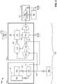
FIG. 1 is a block diagram illustrating a system that includes an ECS and components that can be used to supply air to the ECS according to an arrangement that is outside of the scope of the claims; andFIG. 2 is a block diagram illustrating a system that includes an ECS and components that can be used to supply air to the ECS according to an embodiment.- Embodiments of the present invention that are described in greater detail below may improve the efficiency of engine bleed air extraction by utilizing more of the bleed air energy contained in the bleed air stream coming out of a compressor section of a turbine engine than in conventional systems. Typically, all of the cabin/flight deck air is provided by the engine bleed system. In embodiments disclosed herein, only a portion of the required cabin air is provided through this method. The remaining portion of the cabin/flight deck air is provided by either ram air extraction at prevailing static conditions of the atmosphere, or from lower pressure fan air extraction, depending upon which embodiment of the invention is employed. However, two air streams at different pressures cannot be mixed without some pressure reduction in the higher energy stream (bleed air) or pressure increase in the lower energy stream (ram air). In embodiments disclosed herein, excess pressure in the bleed air is used to drive a turbocompressor that pressurizes the air delivered from the ram air. Through a control scheme that adjusts the flowrate from each air source, the result is a set of two air streams at identical pressures that may be easily combined, even though they will likely be at different temperatures. Advantageously, existing excess pressure energy in the bleed air is used as opposed to being lost in a conventional system that throttles down the pressure to meet distribution system requirements.
FIG. 1 illustrates asystem 100 that includes anair providing system 102 coupled to a cabin air recirculation system. Thesystem 100 is part of an aircraft and receives input air from outside of the aircraft and provides it to the cabinair recirculation system 104 at a predetermined temperature and a predetermined pressure. The predetermined temperature and pressure can be varied in time and, as such, may respectively be referred to herein as temperature and pressure setpoints or collectively as "setpoints."- The cabin
air recirculation system 104 is formed as is known in the art. The cabinair recirculation system 104 includes amixing chamber 106 that mixes air received from theair providing system 102 with air re-circulated from the passenger cabin orflight deck 108 of an aircraft before it is provided to the passenger cabin orflight deck 108. The particulars of the cabinair recirculation system 104 are known in the art and, as such, will not be discussed further herein. - The illustrated
air providing system 102 includes ableed air supply 110. Thebleed air supply 110 provides bleed air to other parts of theair providing system 102. Thebleed air supply 110 includes anengine 115 that includes at least afan 114 and acompressor section 116. Both thefan 114 and thecompressor 116 are coupled to aprecooling heat exchanger 118. Theprecooling heat exchanger 118 utilizes air from thefan 114 to cool air fromcompressor 116. The air from thefan 114 can be dumped overboard after it cools the air from thecompressor 116 as indicated byarrow 117. In particular, the air that exits thecompressor 116 atnode 120 and that is coupled to theprecooling heat exchanger 118, can be in the range of 900 degrees F (482 degrees C) and at a high pressure. This air is too hot for it to be transferred by ducting or other connecting elements of thesystem 100 that can be formed of aluminum, for example. Thus, the air is reduced to about 400 degrees F (204 degrees C) by theprecooling heat exchanger 118 before being output viaconnection 122. The air remains at a high pressure at this point. The "high pressure" is in the range of 40 psig (276 kPa). Some of the cooled air inconnection 122 can be provided toother systems 130. Theother systems 130 can include, for example, a deicing oranti-icing system 130. - The
air providing system 102 also includes an air pressure/temperature conditioning system 112. The air pressure/temperature conditioning system 112 (or conditioner) receives bleed air from thebleed air supply 110 and provides it to the cabinair recirculation system 104 at the setpoints. InFigure 1 , lower temperature (relative to the temperature of air that comes out of the compressor 116), high pressure air is provided to apower turbine 132 of theconditioner 112. Thepower turbine 132 is coupled to ashaft 134 that drives acompressor 135. It shall be understood thatshaft 134 could be driven by (e.g., cooling turbine 136) or drive other elements and may be segmented or unitary. - Some or all of the bleed air is provided to the
power turbine 132 viaconnection 122. As discussed above, the air is at a high pressure. The air inconnection 122 is going to be mixed with ram air that is at a much lower pressure. As such, the air provided topower turbine 132 is allowed to expand to reduce its pressure to an intermediate value. The term "intermediate" as used herein with respect to pressure refers to a pressure that is lower than the pressure of bleed air that leaves theprecooling heat exchanger 118 and greater than the pressure setpoint. The expansion of the high pressure air causes the air to slightly cool and provides rotational power toshaft 134 and, as such, can be used to drivecompressor 135. The intermediate pressure air leaves thepower turbine 132 and is provided to amix chamber 142. Compressor 135 receives ram air from aram air scoop 138 viaconnection 140. Thecompressor 135 compresses this air to the same intermediate pressure as that output bypower turbine 132. The output of thecompressor 135 is also provided to themix chamber 142. As such, the cooler ram air and hotter bleed air are provided to the mix chamber at the same pressure (e.g., at the intermediate pressure). The amount that air is cooled in the mix chamber is based on the mass flow rates throughpower turbine 132 andcompressor 135 as will be understood by the skilled artisan based on the teachings herein.- The mixed air that exits the
mix chamber 142 indicated atnode 146 is now at a lower temperature than the temperature of the air that exited thepower turbine 132. This air could be at or about a desired temperature for provision to cabinair recirculation system 104 or to coolingturbine 136. However, in some cases it may be desirable to further lower the temperature. In such a case, air that exits themix chamber 142 can be provided to an optionalsecondary heat exchanger 144 to lower the temperature to a desired level. Thesecondary heat exchanger 144 is coupled to aram fan 150 that draws cooling air fromram scoop 138 through thesecondary heat exchanger 144. The amount of ram air required in thesecondary heat exchanger 144 is related to the amount of fan air used in theprecooling heat exchanger 118. - The air that exits the mix chamber 142 (whether cooled in
secondary heat exchanger 144 or not) is provided to coolingturbine 136. The coolingturbine 136 is coupled toshaft 134 so the combined work generated by both thepower turbine 132 and the coolingturbine 136 matches the work required by thecompressor 135 and the ram fan 150 (if needed), with the exception of some lost work due to windage and bearing friction. All components directly coupled to theshaft 134 rotate at the same speed. The exit stream of the coolingturbine 136 is at temperature and pressure set points and, as such, can be provided to the cabinair recirculation system 104. - As described above, excess pressure in the bleed stream is extracted by
power turbine 132 and used to drive acompressor 135 to pressurize the ram air fromram scoop 138. By adjusting the flowrate from each air source, the result is a set of two air streams at identical pressures that may be easily combined, even though they will likely be at different temperatures. In contrast to the prior art where excess pressure in the bleed stream is throttled and lost, existing excess pressure energy in the bleed stream is used. Indeed, thermodynamic analysis of the arrangement ofFIG. 1 (as well as that ofFIG. 2 ) indicates that both bleed and ram air requirements may be reduced as compared to conventional systems. Reduction in the amount of bleed air can lead to a reduction in fuel required byengine 115. FIG. 2 illustrates an embodiment of the present invention. In this embodiment, the input tocompressor 135 is provided from the output ofprecooling heat exchanger 118 rather than from theram air scoop 138 as inFIG. 1 . As such, the combined flowrates of air fromcompressor 116 andfan 114 are controlled to equal the desired cabin fresh air flowrate. In this embodiment, ram air fromram scoop 138 is used simply to precondition the blended flow stream atsecondary heat exchanger 144 prior to entering the coolingturbine 136 to ensure that air exitingcooling turbine 136 meets the setpoints.- It shall be understood that one or all of the
power turbine 134,compressor 135,fan 150 and coolingturbine 136 can be coupled to asingle shaft 134. - In view of the above disclosure, it will be realized that one or more of the advantages described over the prior art described below may be realized. The advantages may include: improved utilization of high energy engine bleed air streams resulting in better fuel economy across the aircraft mission spectrum; reduced component size, particularly for the precooler and secondary heat exchangers due to better temperature management; elimination of engine bleed pressure regulation and simplification of the engine bleed shut off valve; and provision for appropriately conditioned anti-icing (or de-icing) air to satisfy existing systems.
- In the embodiment described above, the intermediate pressure of the blended flow stream is allowed to "float" to minimize the high-energy bleed air extraction flowrate, without compromising the material limitations of the air distribution system. One of ordinary skill will realize that in one embodiment, a
control system can be utilized to determine the optimum intermediate pressure, air stream flowrates, andshaft 134 speed to maximize vehicle energy efficiency. - While the invention has been described in detail in connection with only a limited number of embodiments, it should be readily understood that the invention is not limited to such disclosed embodiments. Rather, the invention can be modified to incorporate any number of variations, alterations, substitutions or equivalent arrangements not heretofore described, but which may be commensurate with the scope of the invention. Additionally, while various embodiments of the invention have been described, it is to be understood that aspects of the invention may include only some of the described embodiments. Accordingly, the invention is not to be seen as limited by the foregoing description, but is only limited by the scope of the appended claims.
Claims (7)
- An aircraft air provision system (102) comprising:a power turbine (132) that receives bleed air at a first pressure and that provides rotational energy to a shaft (134) and outputs output air at an intermediate pressure;a compressor (135) coupled to the shaft that receives input air at a second pressure that is lower than the first pressure and outputs compressed air having a pressure equal to the intermediate pressure;a mix chamber (142) coupled to outputs of both the power turbine and the compressor where the output air and the compressed air are mixed; anda cooling turbine (136) coupled to the shaft and that is in fluid communication with an output of the mix chamber;wherein the bleed air is received from a bleed air supply (110) that includes an engine (115) having a compressor section (116),wherein a precooling heat exchanger (118) is in fluid communication with an input of the power turbine (132) and configured to cool air exiting the compressor section (116), andwherein the precooling heat exchanger (118) utilizes air from a fan (114) of the engine (115) to cool air exiting the compressor section (116),characterised in thatthe input air for the compressor (135) is received from an output of the precooling heat exchanger.
- The system of claim 1, further comprising:
a heat exchanger (144) coupled between the mix chamber (142) and the cooling turbine (136) that utilizes air from a same source as the input air to cool air that exits the output of the mix chamber. - The system of claim 2, further comprising:
a fan (150) coupled to the shaft (134), wherein the fan draws air through the heat exchanger (144). - The system of any preceding claim, further comprising:
a cabin air recirculation system (104) coupled to an output of the cooling turbine (136). - A method of providing air to a cabin of an aircraft comprising:providing bleed air to a power turbine (132) at a first pressure to produce rotational energy on a shaft (134) and produce output air at an intermediate pressure;compressing air at a second pressure, in a compressor (135) coupled to the shaft, into compressed air having a pressure equal to the intermediate pressure, wherein the second pressure is less than the first pressure;providing the output air and the compressed air having a pressure at the intermediate pressure to a mix chamber (142) coupled to outputs of both the power turbine (132) and the compressor (135);mixing the compressed air and the output air in the mix chamber (142) to form mixed air;providing the mixed air to a cooling turbine (136) coupled to the shaft (134);wherein the bleed air is provided by a bleed air supply (110) that includes an engine (115) having a compressor section (116),cooling the bleed air in a precooling heat exchanger (118) before providing it to the power turbine (132);wherein the precooling heat exchanger (118) utilizes air from a fan (114) of the engine (115) to cool air exiting the compressor section (116); andwherein input air to compress in the compressor (135) is received from an output of the precooling heat exchanger (118).
- The method of claim 5, wherein input air to compress is received from a ram air scoop (138).
- The method of any of claims 5 or 6, further comprising:
cooling the mixed air before providing it to the cooling turbine (136).
Applications Claiming Priority (1)
| Application Number | Priority Date | Filing Date | Title |
|---|---|---|---|
| US13/305,205US9555893B2 (en) | 2011-11-28 | 2011-11-28 | Blended flow air cycle system for environmental control |
Publications (3)
| Publication Number | Publication Date |
|---|---|
| EP2597036A2 EP2597036A2 (en) | 2013-05-29 |
| EP2597036A3 EP2597036A3 (en) | 2017-03-29 |
| EP2597036B1true EP2597036B1 (en) | 2019-05-01 |
Family
ID=47294697
Family Applications (1)
| Application Number | Title | Priority Date | Filing Date |
|---|---|---|---|
| EP12194488.8AActiveEP2597036B1 (en) | 2011-11-28 | 2012-11-27 | Blended flow air cycle system for environmental control |
Country Status (2)
| Country | Link |
|---|---|
| US (3) | US9555893B2 (en) |
| EP (1) | EP2597036B1 (en) |
Families Citing this family (46)
| Publication number | Priority date | Publication date | Assignee | Title |
|---|---|---|---|---|
| DK2386682T3 (en) | 2010-04-27 | 2014-06-23 | Omya Int Ag | Process for preparing structured materials using nano-fibrillar cellulose gels |
| US9016078B2 (en)* | 2011-11-17 | 2015-04-28 | The Boeing Company | Fuel tank flammability reduction and inerting system and methods thereof |
| US9555893B2 (en) | 2011-11-28 | 2017-01-31 | Hamilton Sundstrand Corporation | Blended flow air cycle system for environmental control |
| EP2754611A1 (en)* | 2013-01-10 | 2014-07-16 | Airbus Operations GmbH | Aircraft air conditioning system and method of operating an aircraft air conditioning system |
| US10745136B2 (en) | 2013-08-29 | 2020-08-18 | Hamilton Sunstrand Corporation | Environmental control system including a compressing device |
| US9580180B2 (en) | 2014-03-07 | 2017-02-28 | Honeywell International Inc. | Low-pressure bleed air aircraft environmental control system |
| EP2915746A1 (en) | 2014-03-07 | 2015-09-09 | Airbus Operations GmbH | Aircraft air conditioning system and method of operating an aircraft air conditioning system |
| US9656756B2 (en)* | 2014-03-10 | 2017-05-23 | The Boeing Company | Turbo-compressor system and method for extracting energy from an aircraft engine |
| EP2998223B1 (en)* | 2014-09-19 | 2018-12-05 | Airbus Operations GmbH | Aircraft air conditioning system and method of operating an aircraft air conditioning system |
| US10549860B2 (en)* | 2014-11-25 | 2020-02-04 | Hamilton Sundstrand Corporation | Environmental control system utilizing cabin air to drive a power turbine of an air cycle machine |
| US11466904B2 (en) | 2014-11-25 | 2022-10-11 | Hamilton Sundstrand Corporation | Environmental control system utilizing cabin air to drive a power turbine of an air cycle machine and utilizing multiple mix points for recirculation air in accordance with pressure mode |
| US10934881B2 (en)* | 2015-04-24 | 2021-03-02 | Hamilton Sunstrand Corporation | Environmental control system mixing cabin discharge air with bleed air during a cycle |
| EP3303134B1 (en) | 2015-06-08 | 2024-08-07 | Hamilton Sundstrand Corporation | No primary heat exchanger and bleed air (cabin discharge air) assist |
| US10954858B2 (en)* | 2015-06-18 | 2021-03-23 | Hamilton Sunstrand Corporation | Plate fin heat exchanger |
| US10011361B2 (en)* | 2015-11-16 | 2018-07-03 | Textron Innovations Inc. | Aircraft environmental control system providing improved performance and backup temperature control |
| CN105523185B (en)* | 2015-12-21 | 2018-04-10 | 中国航空工业集团公司西安飞机设计研究所 | A kind of aircraft passenger compartment temperature control system |
| US10850853B2 (en)* | 2016-04-22 | 2020-12-01 | Hamilton Sunstrand Corporation | Environmental control system utilizing bleed pressure assist |
| EP3269645A3 (en) | 2016-05-26 | 2018-03-07 | Hamilton Sundstrand Corporation | Mixing bleed and ram air using a two turbine architecture with an outflow heat exchanger |
| US11506121B2 (en) | 2016-05-26 | 2022-11-22 | Hamilton Sundstrand Corporation | Multiple nozzle configurations for a turbine of an environmental control system |
| US11047237B2 (en)* | 2016-05-26 | 2021-06-29 | Hamilton Sunstrand Corporation | Mixing ram and bleed air in a dual entry turbine system |
| US10773807B2 (en) | 2016-05-26 | 2020-09-15 | Hamilton Sunstrand Corporation | Energy flow of an advanced environmental control system |
| EP4019403B1 (en) | 2016-05-26 | 2024-07-03 | Hamilton Sundstrand Corporation | Mixing ram and bleed air in a dual entry turbine system |
| EP3254970B1 (en) | 2016-05-26 | 2020-04-29 | Hamilton Sundstrand Corporation | An environmental control system with an outflow heat exchanger |
| US10597162B2 (en)* | 2016-05-26 | 2020-03-24 | Hamilton Sundstrand Corporation | Mixing bleed and ram air at a turbine inlet |
| US10870490B2 (en) | 2016-05-26 | 2020-12-22 | Hamilton Sunstrand Corporation | Energy flow |
| US10604263B2 (en) | 2016-05-26 | 2020-03-31 | Hamilton Sundstrand Corporation | Mixing bleed and ram air using a dual use turbine system |
| EP3248876B1 (en)* | 2016-05-26 | 2023-04-26 | Hamilton Sundstrand Corporation | Mixing bleed and ram air at a turbine inlet of a compressing device |
| US10137993B2 (en) | 2016-05-26 | 2018-11-27 | Hamilton Sundstrand Corporation | Mixing bleed and ram air using an air cycle machine with two turbines |
| US11377216B2 (en)* | 2016-08-23 | 2022-07-05 | Ge Aviation Systems Llc | Advanced method and aircraft for pre-cooling an environmental control system using a dual compressor four wheel turbo-machine |
| US10384785B2 (en) | 2017-02-17 | 2019-08-20 | Hamilton Sundstrand Corporation | Two mode system that provides bleed and outside air or just outside air |
| US11427331B2 (en)* | 2017-04-13 | 2022-08-30 | Hamilton Sundstrand Corporation | Fresh air and recirculation air mixing optimization |
| US10473037B2 (en) | 2017-05-22 | 2019-11-12 | United Technologies Corporation | Passively-driven bleed source switching |
| US10843804B2 (en)* | 2017-08-01 | 2020-11-24 | Honeywell International Inc. | Cabin outflow air energy optimized cabin pressurizing system |
| EP3672872A1 (en)* | 2017-08-23 | 2020-07-01 | Bombardier Inc. | Apparatus and methods for providing air to pneumatic loads onboard aircraft |
| US10611487B2 (en)* | 2018-01-16 | 2020-04-07 | The Boeing Company | Vehicle air conditioning pack with air cycle assembly |
| US11396378B2 (en)* | 2018-01-24 | 2022-07-26 | Hamilton Sundstrand Corporation | ECS dual entry ram inlet plenum |
| US11377217B2 (en) | 2019-06-11 | 2022-07-05 | Hamilton Sundstrand Corporation | Using bleed air to supply outside air to a cabin |
| US11332252B2 (en) | 2019-06-11 | 2022-05-17 | Hamilton Sundstrand Corporation | Using bleed air to supply outside air to a cabin |
| US11390386B2 (en) | 2019-08-27 | 2022-07-19 | Pratt & Whitney Canada Corp. | System and method for increasing bleed air flow to a heat exchanger with a fluid-driven fluid propeller |
| US11215124B2 (en) | 2019-08-27 | 2022-01-04 | Pratt & Whitney Canada Corp. | System and method for conditioning a fluid using bleed air from a bypass duct of a turbofan engine |
| US11603795B2 (en) | 2019-10-23 | 2023-03-14 | Hamilton Sundstrand Corporation | Generator with air-cycle cooling |
| US12269602B2 (en)* | 2019-12-19 | 2025-04-08 | Hamilton Sundstrand Corporation | Air cycle machines, air cycle machine systems, and methods of controlling air flow in air cycle machines |
| DE102020105132A1 (en) | 2020-02-27 | 2021-09-02 | Dr. Ing. H.C. F. Porsche Aktiengesellschaft | Cooling arrangement for cooling the charge air of a supercharged internal combustion engine |
| US12097962B2 (en) | 2020-07-30 | 2024-09-24 | Hamilton Sundstrand Corporation | Aircraft environmental control system |
| EP3945030B1 (en) | 2020-07-30 | 2025-05-14 | Hamilton Sundstrand Corporation | Aircraft environmental control system |
| US11939065B2 (en) | 2020-07-30 | 2024-03-26 | Hamilton Sundstrand Corporation | Aircraft environmental control system |
Family Cites Families (23)
| Publication number | Priority date | Publication date | Assignee | Title |
|---|---|---|---|---|
| US5086622A (en)* | 1990-08-17 | 1992-02-11 | United Technologies Corporation | Environmental control system condensing cycle |
| US5452573A (en)* | 1994-01-31 | 1995-09-26 | United Technologies Corporation | High pressure air source for aircraft and engine requirements |
| US5442905A (en)* | 1994-04-08 | 1995-08-22 | Alliedsignal Inc. | Integrated power and cooling environmental control system |
| GB9508043D0 (en)* | 1995-04-20 | 1995-06-07 | British Aerospace | Environmental control system |
| US5911388A (en)* | 1997-01-15 | 1999-06-15 | Sundstrand Corporation | Environmental control system with energy recovery and bleed air assist |
| US6182435B1 (en)* | 1997-06-05 | 2001-02-06 | Hamilton Sundstrand Corporation | Thermal and energy management method and apparatus for an aircraft |
| US5967461A (en)* | 1997-07-02 | 1999-10-19 | Mcdonnell Douglas Corp. | High efficiency environmental control systems and methods |
| US6375849B1 (en)* | 1998-04-03 | 2002-04-23 | Alliedsignal Inc. | Integrated environmental control system and humidification system |
| DE19963280C1 (en) | 1999-12-27 | 2001-08-23 | Liebherr Aerospace Gmbh | Air conditioning system for aircraft cabins |
| DE10009373C2 (en) | 2000-02-29 | 2002-03-14 | Airbus Gmbh | Air conditioning system for a commercial aircraft |
| US6427471B1 (en) | 2000-02-29 | 2002-08-06 | Shimadzu Corporation | Air cycle machine and air conditioning system using the same |
| US6457318B1 (en)* | 2000-11-07 | 2002-10-01 | Honeywell International Inc. | Recirculating regenerative air cycle |
| US6681592B1 (en)* | 2001-02-16 | 2004-01-27 | Hamilton Sundstrand Corporation | Electrically driven aircraft cabin ventilation and environmental control system |
| US6684660B1 (en)* | 2002-08-08 | 2004-02-03 | Hamilton Sundstrand | Pneumatic cabin super charger |
| US6848261B2 (en)* | 2003-04-03 | 2005-02-01 | Honeywell International Inc. | Condensing cycle with energy recovery augmentation |
| US7171819B2 (en)* | 2005-01-21 | 2007-02-06 | Honeywell International, Inc. | Indirect regenerative air cycle for integrated power and cooling machines |
| US7305842B1 (en)* | 2005-05-23 | 2007-12-11 | Peter Schiff | Environmental control system and method for an aircraft |
| US7334422B2 (en)* | 2005-11-29 | 2008-02-26 | Hamilton Sundstrand Corporation | Cabin air conditioning system with liquid cooling for power electronics |
| US7987683B2 (en)* | 2006-02-20 | 2011-08-02 | Hamilton Sundstrand Corporation | Expendable turbine driven compression cycle cooling system |
| US7673459B2 (en)* | 2006-04-05 | 2010-03-09 | General Electric Company | System and method for providing air to a compressor of an aircraft auxiliary gas turbine engine |
| US7624592B2 (en)* | 2006-05-17 | 2009-12-01 | Northrop Grumman Corporation | Flexible power and thermal architectures using a common machine |
| US7607318B2 (en)* | 2006-05-25 | 2009-10-27 | Honeywell International Inc. | Integrated environmental control and auxiliary power system for an aircraft |
| US9555893B2 (en) | 2011-11-28 | 2017-01-31 | Hamilton Sundstrand Corporation | Blended flow air cycle system for environmental control |
- 2011
- 2011-11-28USUS13/305,205patent/US9555893B2/enactiveActive
- 2012
- 2012-11-27EPEP12194488.8Apatent/EP2597036B1/enactiveActive
- 2016
- 2016-08-08USUS15/231,191patent/US10059458B2/enactiveActive
- 2018
- 2018-07-13USUS16/035,058patent/US10669032B2/enactiveActive
Non-Patent Citations (1)
| Title |
|---|
| None* |
Also Published As
| Publication number | Publication date |
|---|---|
| EP2597036A3 (en) | 2017-03-29 |
| US9555893B2 (en) | 2017-01-31 |
| US20130133348A1 (en) | 2013-05-30 |
| US20180327099A1 (en) | 2018-11-15 |
| US20160340048A1 (en) | 2016-11-24 |
| US10669032B2 (en) | 2020-06-02 |
| US10059458B2 (en) | 2018-08-28 |
| EP2597036A2 (en) | 2013-05-29 |
Similar Documents
| Publication | Publication Date | Title |
|---|---|---|
| US10669032B2 (en) | Blended flow air cycle system for environmental control | |
| EP2947012B1 (en) | Aircraft air conditioning system and method of its operation | |
| EP1295789B1 (en) | Environmental control system | |
| JP6165413B2 (en) | Environmental control system supply precooler bypass | |
| US9580179B2 (en) | Air conditioning system for an aircraft passenger compartment | |
| EP1855943B1 (en) | Air system | |
| EP2918497B1 (en) | Turbo-compressor system and method for extracting energy from an aircraft engine | |
| US8572996B2 (en) | Air conditioning system with hybrid mode bleed air operation | |
| US9169024B2 (en) | Environmental control system with closed loop pressure cycle | |
| US9254920B2 (en) | Aircraft energy management system including engine fan discharge air boosted environmental control system | |
| EP3173337B1 (en) | Aircraft air conditioning system with ambient air supply and method for operating such an aircraft air conditioning system | |
| US20130061611A1 (en) | Air conditioning system with hybrid operation for an aircraft | |
| CN109789930B (en) | Auxiliary air supply for an aircraft | |
| US11046440B2 (en) | Aircraft cabin environmental control system and method and aircraft equipped with such control system | |
| EP1491443B1 (en) | Air conditioning system | |
| EP3187418A1 (en) | Air conditioning system | |
| EP3747772B1 (en) | Aircraft environmental control system |
Legal Events
| Date | Code | Title | Description |
|---|---|---|---|
| PUAI | Public reference made under article 153(3) epc to a published international application that has entered the european phase | Free format text:ORIGINAL CODE: 0009012 | |
| AK | Designated contracting states | Kind code of ref document:A2 Designated state(s):AL AT BE BG CH CY CZ DE DK EE ES FI FR GB GR HR HU IE IS IT LI LT LU LV MC MK MT NL NO PL PT RO RS SE SI SK SM TR | |
| AX | Request for extension of the european patent | Extension state:BA ME | |
| PUAL | Search report despatched | Free format text:ORIGINAL CODE: 0009013 | |
| AK | Designated contracting states | Kind code of ref document:A3 Designated state(s):AL AT BE BG CH CY CZ DE DK EE ES FI FR GB GR HR HU IE IS IT LI LT LU LV MC MK MT NL NO PL PT RO RS SE SI SK SM TR | |
| AX | Request for extension of the european patent | Extension state:BA ME | |
| RIC1 | Information provided on ipc code assigned before grant | Ipc:B64D 13/06 20060101AFI20170223BHEP | |
| STAA | Information on the status of an ep patent application or granted ep patent | Free format text:STATUS: REQUEST FOR EXAMINATION WAS MADE | |
| 17P | Request for examination filed | Effective date:20170921 | |
| RBV | Designated contracting states (corrected) | Designated state(s):AL AT BE BG CH CY CZ DE DK EE ES FI FR GB GR HR HU IE IS IT LI LT LU LV MC MK MT NL NO PL PT RO RS SE SI SK SM TR | |
| REG | Reference to a national code | Ref country code:DE Ref legal event code:R079 Ref document number:602012059543 Country of ref document:DE Free format text:PREVIOUS MAIN CLASS: B64D0013080000 Ipc:B64D0013060000 | |
| GRAP | Despatch of communication of intention to grant a patent | Free format text:ORIGINAL CODE: EPIDOSNIGR1 | |
| RIC1 | Information provided on ipc code assigned before grant | Ipc:B64D 13/06 20060101AFI20181002BHEP | |
| STAA | Information on the status of an ep patent application or granted ep patent | Free format text:STATUS: GRANT OF PATENT IS INTENDED | |
| INTG | Intention to grant announced | Effective date:20181108 | |
| GRAS | Grant fee paid | Free format text:ORIGINAL CODE: EPIDOSNIGR3 | |
| GRAA | (expected) grant | Free format text:ORIGINAL CODE: 0009210 | |
| STAA | Information on the status of an ep patent application or granted ep patent | Free format text:STATUS: THE PATENT HAS BEEN GRANTED | |
| AK | Designated contracting states | Kind code of ref document:B1 Designated state(s):AL AT BE BG CH CY CZ DE DK EE ES FI FR GB GR HR HU IE IS IT LI LT LU LV MC MK MT NL NO PL PT RO RS SE SI SK SM TR | |
| REG | Reference to a national code | Ref country code:GB Ref legal event code:FG4D | |
| REG | Reference to a national code | Ref country code:CH Ref legal event code:EP Ref country code:AT Ref legal event code:REF Ref document number:1126600 Country of ref document:AT Kind code of ref document:T Effective date:20190515 | |
| REG | Reference to a national code | Ref country code:DE Ref legal event code:R096 Ref document number:602012059543 Country of ref document:DE | |
| REG | Reference to a national code | Ref country code:IE Ref legal event code:FG4D | |
| REG | Reference to a national code | Ref country code:NL Ref legal event code:MP Effective date:20190501 | |
| REG | Reference to a national code | Ref country code:LT Ref legal event code:MG4D | |
| PG25 | Lapsed in a contracting state [announced via postgrant information from national office to epo] | Ref country code:HR Free format text:LAPSE BECAUSE OF FAILURE TO SUBMIT A TRANSLATION OF THE DESCRIPTION OR TO PAY THE FEE WITHIN THE PRESCRIBED TIME-LIMIT Effective date:20190501 Ref country code:LT Free format text:LAPSE BECAUSE OF FAILURE TO SUBMIT A TRANSLATION OF THE DESCRIPTION OR TO PAY THE FEE WITHIN THE PRESCRIBED TIME-LIMIT Effective date:20190501 Ref country code:SE Free format text:LAPSE BECAUSE OF FAILURE TO SUBMIT A TRANSLATION OF THE DESCRIPTION OR TO PAY THE FEE WITHIN THE PRESCRIBED TIME-LIMIT Effective date:20190501 Ref country code:NL Free format text:LAPSE BECAUSE OF FAILURE TO SUBMIT A TRANSLATION OF THE DESCRIPTION OR TO PAY THE FEE WITHIN THE PRESCRIBED TIME-LIMIT Effective date:20190501 Ref country code:FI Free format text:LAPSE BECAUSE OF FAILURE TO SUBMIT A TRANSLATION OF THE DESCRIPTION OR TO PAY THE FEE WITHIN THE PRESCRIBED TIME-LIMIT Effective date:20190501 Ref country code:AL Free format text:LAPSE BECAUSE OF FAILURE TO SUBMIT A TRANSLATION OF THE DESCRIPTION OR TO PAY THE FEE WITHIN THE PRESCRIBED TIME-LIMIT Effective date:20190501 Ref country code:PT Free format text:LAPSE BECAUSE OF FAILURE TO SUBMIT A TRANSLATION OF THE DESCRIPTION OR TO PAY THE FEE WITHIN THE PRESCRIBED TIME-LIMIT Effective date:20190901 Ref country code:ES Free format text:LAPSE BECAUSE OF FAILURE TO SUBMIT A TRANSLATION OF THE DESCRIPTION OR TO PAY THE FEE WITHIN THE PRESCRIBED TIME-LIMIT Effective date:20190501 Ref country code:NO Free format text:LAPSE BECAUSE OF FAILURE TO SUBMIT A TRANSLATION OF THE DESCRIPTION OR TO PAY THE FEE WITHIN THE PRESCRIBED TIME-LIMIT Effective date:20190801 | |
| PG25 | Lapsed in a contracting state [announced via postgrant information from national office to epo] | Ref country code:BG Free format text:LAPSE BECAUSE OF FAILURE TO SUBMIT A TRANSLATION OF THE DESCRIPTION OR TO PAY THE FEE WITHIN THE PRESCRIBED TIME-LIMIT Effective date:20190801 Ref country code:GR Free format text:LAPSE BECAUSE OF FAILURE TO SUBMIT A TRANSLATION OF THE DESCRIPTION OR TO PAY THE FEE WITHIN THE PRESCRIBED TIME-LIMIT Effective date:20190802 Ref country code:LV Free format text:LAPSE BECAUSE OF FAILURE TO SUBMIT A TRANSLATION OF THE DESCRIPTION OR TO PAY THE FEE WITHIN THE PRESCRIBED TIME-LIMIT Effective date:20190501 Ref country code:RS Free format text:LAPSE BECAUSE OF FAILURE TO SUBMIT A TRANSLATION OF THE DESCRIPTION OR TO PAY THE FEE WITHIN THE PRESCRIBED TIME-LIMIT Effective date:20190501 | |
| REG | Reference to a national code | Ref country code:AT Ref legal event code:MK05 Ref document number:1126600 Country of ref document:AT Kind code of ref document:T Effective date:20190501 | |
| PG25 | Lapsed in a contracting state [announced via postgrant information from national office to epo] | Ref country code:IS Free format text:LAPSE BECAUSE OF FAILURE TO SUBMIT A TRANSLATION OF THE DESCRIPTION OR TO PAY THE FEE WITHIN THE PRESCRIBED TIME-LIMIT Effective date:20190901 | |
| PG25 | Lapsed in a contracting state [announced via postgrant information from national office to epo] | Ref country code:EE Free format text:LAPSE BECAUSE OF FAILURE TO SUBMIT A TRANSLATION OF THE DESCRIPTION OR TO PAY THE FEE WITHIN THE PRESCRIBED TIME-LIMIT Effective date:20190501 Ref country code:DK Free format text:LAPSE BECAUSE OF FAILURE TO SUBMIT A TRANSLATION OF THE DESCRIPTION OR TO PAY THE FEE WITHIN THE PRESCRIBED TIME-LIMIT Effective date:20190501 Ref country code:AT Free format text:LAPSE BECAUSE OF FAILURE TO SUBMIT A TRANSLATION OF THE DESCRIPTION OR TO PAY THE FEE WITHIN THE PRESCRIBED TIME-LIMIT Effective date:20190501 Ref country code:RO Free format text:LAPSE BECAUSE OF FAILURE TO SUBMIT A TRANSLATION OF THE DESCRIPTION OR TO PAY THE FEE WITHIN THE PRESCRIBED TIME-LIMIT Effective date:20190501 Ref country code:CZ Free format text:LAPSE BECAUSE OF FAILURE TO SUBMIT A TRANSLATION OF THE DESCRIPTION OR TO PAY THE FEE WITHIN THE PRESCRIBED TIME-LIMIT Effective date:20190501 Ref country code:SK Free format text:LAPSE BECAUSE OF FAILURE TO SUBMIT A TRANSLATION OF THE DESCRIPTION OR TO PAY THE FEE WITHIN THE PRESCRIBED TIME-LIMIT Effective date:20190501 | |
| REG | Reference to a national code | Ref country code:DE Ref legal event code:R097 Ref document number:602012059543 Country of ref document:DE | |
| PG25 | Lapsed in a contracting state [announced via postgrant information from national office to epo] | Ref country code:SM Free format text:LAPSE BECAUSE OF FAILURE TO SUBMIT A TRANSLATION OF THE DESCRIPTION OR TO PAY THE FEE WITHIN THE PRESCRIBED TIME-LIMIT Effective date:20190501 Ref country code:IT Free format text:LAPSE BECAUSE OF FAILURE TO SUBMIT A TRANSLATION OF THE DESCRIPTION OR TO PAY THE FEE WITHIN THE PRESCRIBED TIME-LIMIT Effective date:20190501 | |
| PLBE | No opposition filed within time limit | Free format text:ORIGINAL CODE: 0009261 | |
| STAA | Information on the status of an ep patent application or granted ep patent | Free format text:STATUS: NO OPPOSITION FILED WITHIN TIME LIMIT | |
| PG25 | Lapsed in a contracting state [announced via postgrant information from national office to epo] | Ref country code:TR Free format text:LAPSE BECAUSE OF FAILURE TO SUBMIT A TRANSLATION OF THE DESCRIPTION OR TO PAY THE FEE WITHIN THE PRESCRIBED TIME-LIMIT Effective date:20190501 | |
| 26N | No opposition filed | Effective date:20200204 | |
| PG25 | Lapsed in a contracting state [announced via postgrant information from national office to epo] | Ref country code:PL Free format text:LAPSE BECAUSE OF FAILURE TO SUBMIT A TRANSLATION OF THE DESCRIPTION OR TO PAY THE FEE WITHIN THE PRESCRIBED TIME-LIMIT Effective date:20190501 | |
| PG25 | Lapsed in a contracting state [announced via postgrant information from national office to epo] | Ref country code:SI Free format text:LAPSE BECAUSE OF FAILURE TO SUBMIT A TRANSLATION OF THE DESCRIPTION OR TO PAY THE FEE WITHIN THE PRESCRIBED TIME-LIMIT Effective date:20190501 | |
| REG | Reference to a national code | Ref country code:DE Ref legal event code:R119 Ref document number:602012059543 Country of ref document:DE | |
| REG | Reference to a national code | Ref country code:CH Ref legal event code:PL | |
| PG25 | Lapsed in a contracting state [announced via postgrant information from national office to epo] | Ref country code:LI Free format text:LAPSE BECAUSE OF NON-PAYMENT OF DUE FEES Effective date:20191130 Ref country code:LU Free format text:LAPSE BECAUSE OF NON-PAYMENT OF DUE FEES Effective date:20191127 Ref country code:CH Free format text:LAPSE BECAUSE OF NON-PAYMENT OF DUE FEES Effective date:20191130 Ref country code:MC Free format text:LAPSE BECAUSE OF FAILURE TO SUBMIT A TRANSLATION OF THE DESCRIPTION OR TO PAY THE FEE WITHIN THE PRESCRIBED TIME-LIMIT Effective date:20190501 | |
| REG | Reference to a national code | Ref country code:BE Ref legal event code:MM Effective date:20191130 | |
| PG25 | Lapsed in a contracting state [announced via postgrant information from national office to epo] | Ref country code:IE Free format text:LAPSE BECAUSE OF NON-PAYMENT OF DUE FEES Effective date:20191127 Ref country code:DE Free format text:LAPSE BECAUSE OF NON-PAYMENT OF DUE FEES Effective date:20200603 | |
| PG25 | Lapsed in a contracting state [announced via postgrant information from national office to epo] | Ref country code:BE Free format text:LAPSE BECAUSE OF NON-PAYMENT OF DUE FEES Effective date:20191130 | |
| PG25 | Lapsed in a contracting state [announced via postgrant information from national office to epo] | Ref country code:CY Free format text:LAPSE BECAUSE OF FAILURE TO SUBMIT A TRANSLATION OF THE DESCRIPTION OR TO PAY THE FEE WITHIN THE PRESCRIBED TIME-LIMIT Effective date:20190501 | |
| PG25 | Lapsed in a contracting state [announced via postgrant information from national office to epo] | Ref country code:HU Free format text:LAPSE BECAUSE OF FAILURE TO SUBMIT A TRANSLATION OF THE DESCRIPTION OR TO PAY THE FEE WITHIN THE PRESCRIBED TIME-LIMIT; INVALID AB INITIO Effective date:20121127 Ref country code:MT Free format text:LAPSE BECAUSE OF FAILURE TO SUBMIT A TRANSLATION OF THE DESCRIPTION OR TO PAY THE FEE WITHIN THE PRESCRIBED TIME-LIMIT Effective date:20190501 | |
| PG25 | Lapsed in a contracting state [announced via postgrant information from national office to epo] | Ref country code:MK Free format text:LAPSE BECAUSE OF FAILURE TO SUBMIT A TRANSLATION OF THE DESCRIPTION OR TO PAY THE FEE WITHIN THE PRESCRIBED TIME-LIMIT Effective date:20190501 | |
| P01 | Opt-out of the competence of the unified patent court (upc) registered | Effective date:20230522 | |
| PGFP | Annual fee paid to national office [announced via postgrant information from national office to epo] | Ref country code:GB Payment date:20241023 Year of fee payment:13 | |
| PGFP | Annual fee paid to national office [announced via postgrant information from national office to epo] | Ref country code:FR Payment date:20241022 Year of fee payment:13 |