EP2596756A1 - Implanting apparatus - Google Patents
Implanting apparatusDownload PDFInfo
- Publication number
- EP2596756A1 EP2596756A1EP20110190135EP11190135AEP2596756A1EP 2596756 A1EP2596756 A1EP 2596756A1EP 20110190135EP20110190135EP 20110190135EP 11190135 AEP11190135 AEP 11190135AEP 2596756 A1EP2596756 A1EP 2596756A1
- Authority
- EP
- European Patent Office
- Prior art keywords
- endoscope
- capsule
- implanting
- expanding sleeve
- working channel
- Prior art date
- Legal status (The legal status is an assumption and is not a legal conclusion. Google has not performed a legal analysis and makes no representation as to the accuracy of the status listed.)
- Granted
Links
- 210000000056organAnatomy0.000claimsdescription33
- 239000008280bloodSubstances0.000claimsdescription14
- 210000004369bloodAnatomy0.000claimsdescription14
- 238000001514detection methodMethods0.000claimsdescription9
- 239000000463materialSubstances0.000claimsdescription6
- 238000000465mouldingMethods0.000claimsdescription6
- 238000012806monitoring deviceMethods0.000claimsdescription3
- 238000004026adhesive bondingMethods0.000claimsdescription2
- 238000002844meltingMethods0.000claimsdescription2
- 230000008018meltingEffects0.000claimsdescription2
- 239000011347resinSubstances0.000claimsdescription2
- 229920005989resinPolymers0.000claimsdescription2
- 210000001035gastrointestinal tractAnatomy0.000description10
- 239000007943implantSubstances0.000description10
- 208000032843HemorrhageDiseases0.000description6
- 238000013461designMethods0.000description5
- 230000000740bleeding effectEffects0.000description4
- 239000002775capsuleSubstances0.000description4
- 229910000639Spring steelInorganic materials0.000description3
- 230000009471actionEffects0.000description3
- 239000012636effectorSubstances0.000description3
- 238000003780insertionMethods0.000description3
- 230000037431insertionEffects0.000description3
- 238000012544monitoring processMethods0.000description3
- 230000003287optical effectEffects0.000description3
- 238000012545processingMethods0.000description3
- 238000000862absorption spectrumMethods0.000description2
- 238000004873anchoringMethods0.000description2
- 230000000694effectsEffects0.000description2
- 238000005538encapsulationMethods0.000description2
- 238000002513implantationMethods0.000description2
- 238000001429visible spectrumMethods0.000description2
- 241000251730ChondrichthyesSpecies0.000description1
- 241001465754MetazoaSpecies0.000description1
- 230000005540biological transmissionEffects0.000description1
- 238000013016dampingMethods0.000description1
- 238000000354decomposition reactionMethods0.000description1
- 239000003814drugSubstances0.000description1
- 229940079593drugDrugs0.000description1
- 238000012377drug deliveryMethods0.000description1
- 210000001198duodenumAnatomy0.000description1
- 239000003792electrolyteSubstances0.000description1
- 238000001839endoscopyMethods0.000description1
- 238000005516engineering processMethods0.000description1
- 210000003238esophagusAnatomy0.000description1
- 238000011156evaluationMethods0.000description1
- 230000007246mechanismEffects0.000description1
- 238000000034methodMethods0.000description1
- 230000008569processEffects0.000description1
- 238000004080punchingMethods0.000description1
- 238000007493shaping processMethods0.000description1
- 230000011664signalingEffects0.000description1
- 241000894007speciesSpecies0.000description1
- 210000002784stomachAnatomy0.000description1
- 239000003826tabletSubstances0.000description1
Images


Classifications
- A—HUMAN NECESSITIES
- A61—MEDICAL OR VETERINARY SCIENCE; HYGIENE
- A61B—DIAGNOSIS; SURGERY; IDENTIFICATION
- A61B17/00—Surgical instruments, devices or methods
- A61B17/10—Surgical instruments, devices or methods for applying or removing wound clamps, e.g. containing only one clamp or staple; Wound clamp magazines
- A—HUMAN NECESSITIES
- A61—MEDICAL OR VETERINARY SCIENCE; HYGIENE
- A61B—DIAGNOSIS; SURGERY; IDENTIFICATION
- A61B17/00—Surgical instruments, devices or methods
- A61B17/12—Surgical instruments, devices or methods for ligaturing or otherwise compressing tubular parts of the body, e.g. blood vessels or umbilical cord
- A61B17/122—Clamps or clips, e.g. for the umbilical cord
- A61B17/1227—Spring clips
- A—HUMAN NECESSITIES
- A61—MEDICAL OR VETERINARY SCIENCE; HYGIENE
- A61B—DIAGNOSIS; SURGERY; IDENTIFICATION
- A61B17/00—Surgical instruments, devices or methods
- A61B17/12—Surgical instruments, devices or methods for ligaturing or otherwise compressing tubular parts of the body, e.g. blood vessels or umbilical cord
- A61B17/128—Surgical instruments, devices or methods for ligaturing or otherwise compressing tubular parts of the body, e.g. blood vessels or umbilical cord for applying or removing clamps or clips
- A61B17/1285—Surgical instruments, devices or methods for ligaturing or otherwise compressing tubular parts of the body, e.g. blood vessels or umbilical cord for applying or removing clamps or clips for minimally invasive surgery
- A—HUMAN NECESSITIES
- A61—MEDICAL OR VETERINARY SCIENCE; HYGIENE
- A61B—DIAGNOSIS; SURGERY; IDENTIFICATION
- A61B5/00—Measuring for diagnostic purposes; Identification of persons
- A61B5/0059—Measuring for diagnostic purposes; Identification of persons using light, e.g. diagnosis by transillumination, diascopy, fluorescence
- A61B5/0082—Measuring for diagnostic purposes; Identification of persons using light, e.g. diagnosis by transillumination, diascopy, fluorescence adapted for particular medical purposes
- A61B5/0084—Measuring for diagnostic purposes; Identification of persons using light, e.g. diagnosis by transillumination, diascopy, fluorescence adapted for particular medical purposes for introduction into the body, e.g. by catheters
- A—HUMAN NECESSITIES
- A61—MEDICAL OR VETERINARY SCIENCE; HYGIENE
- A61B—DIAGNOSIS; SURGERY; IDENTIFICATION
- A61B5/00—Measuring for diagnostic purposes; Identification of persons
- A61B5/02—Detecting, measuring or recording for evaluating the cardiovascular system, e.g. pulse, heart rate, blood pressure or blood flow
- A61B5/02042—Determining blood loss or bleeding, e.g. during a surgical procedure
- A—HUMAN NECESSITIES
- A61—MEDICAL OR VETERINARY SCIENCE; HYGIENE
- A61B—DIAGNOSIS; SURGERY; IDENTIFICATION
- A61B5/00—Measuring for diagnostic purposes; Identification of persons
- A61B5/68—Arrangements of detecting, measuring or recording means, e.g. sensors, in relation to patient
- A61B5/6846—Arrangements of detecting, measuring or recording means, e.g. sensors, in relation to patient specially adapted to be brought in contact with an internal body part, i.e. invasive
- A61B5/6847—Arrangements of detecting, measuring or recording means, e.g. sensors, in relation to patient specially adapted to be brought in contact with an internal body part, i.e. invasive mounted on an invasive device
- A61B5/6861—Capsules, e.g. for swallowing or implanting
- A—HUMAN NECESSITIES
- A61—MEDICAL OR VETERINARY SCIENCE; HYGIENE
- A61B—DIAGNOSIS; SURGERY; IDENTIFICATION
- A61B5/00—Measuring for diagnostic purposes; Identification of persons
- A61B5/68—Arrangements of detecting, measuring or recording means, e.g. sensors, in relation to patient
- A61B5/6846—Arrangements of detecting, measuring or recording means, e.g. sensors, in relation to patient specially adapted to be brought in contact with an internal body part, i.e. invasive
- A61B5/6879—Means for maintaining contact with the body
- A61B5/6884—Clamps or clips
- A—HUMAN NECESSITIES
- A61—MEDICAL OR VETERINARY SCIENCE; HYGIENE
- A61B—DIAGNOSIS; SURGERY; IDENTIFICATION
- A61B2560/00—Constructional details of operational features of apparatus; Accessories for medical measuring apparatus
- A61B2560/06—Accessories for medical measuring apparatus
- A61B2560/063—Devices specially adapted for delivering implantable medical measuring apparatus
- A61B2560/066—Devices specially adapted for delivering implantable medical measuring apparatus catheters therefor
- A—HUMAN NECESSITIES
- A61—MEDICAL OR VETERINARY SCIENCE; HYGIENE
- A61B—DIAGNOSIS; SURGERY; IDENTIFICATION
- A61B5/00—Measuring for diagnostic purposes; Identification of persons
- A61B5/07—Endoradiosondes
- A61B5/076—Permanent implantation
Definitions
- the present inventionrelates to an apparatus or instrument for at least temporarily implanting of capsule-like metering, diagnose and/or monitoring devices, for example blood detection devices or the like preferably in hollow organs of a human or animal body using a tissue clip.
- tissue clip of this speciesis generally known as regards its basic design. For a better comprehension, this tissue clip is described hereinafter in detail with reference to Fig. 1 .
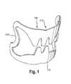
- such a clip 100consists of a mouth-type clamping means having two toothed jaws 110, 120 adapted to be opened and shut via two lateral hinges 130 or by flexible moldings.
- the hinges 130 or the flexible moldingsare preferably formed of spring-elastic straps which during opening the jaws 110, 120 store spring energy which results in a snapping of the jaws 110, 120 at a predetermined clamping force when the jaws 110, 120 are released, i.e. when the hinges 130 or the flexible moldings are actuated.
- each clip 100is punched in one piece out of a spring steel sheet by working a ring having a partially different ring width out of the spring steel sheet.
- Two diametrally opposed ring portions having a large ring widthconstitute the two jaws 110, 120, whereas the two ring portions disposed there between having a narrow ring width form the hinges 130 or the flexible moldings.
- the jaws 110, 120are formed by arching the ring portions having a large ring width in a curved shape, wherein the two ring portions having a narrow ring width are twisted about their longitudinal axis by approx. 180° in order to form the hinges.
- This special shaping of the punched out spring steel sheetcreates the shape of a type of shark mouth having two rows of teeth moving toward each other which are formed by punching out the ring portions having a large ring width.
- the endoscope not shown in detail in Fig. 1usually is equipped with an endoscope head or an endoscope cap which includes, apart from the functions generally required for an endoscope such as lighting, optical system and rinsing means, if necessary, in addition a holding and withdrawing means for the tissue clip.
- This holding and withdrawing meanssubstantially consists of an expanding sleeve as well as a slide operable manually or by remote control which is movable in the longitudinal direction of the endoscope.
- the expanding sleeveis configured such that the already opened tissue clip can be attached to the sleeve in such manner that the clip can be prevented from slipping backwards while being inserted into the hollow organ.
- the slideis positioned axially behind the clip and serves so-to-speak as an axial stop for the clip.
- the slideis moved axially forward and in so doing strips off the clip over the expanding sleeve. Accordingly, the clip is actuated, i.e. the biasing mechanism within the clip described before by way of Figure 1 is released when the latter is stripped off the expanding sleeve and the two jaws of the tissue clip snap to close while clamping the tissue provided there between.
- the reference US 2008/0097182 A1discloses a device for hemorrhage detection being adapted to ensure a continuous monitoring of bleeding within a hollow organ of a human patient which device uses a tissue clip according to the above description for fixing the device at the inner wall of the hollow organ.
- the known devicewill be described in the following text portion with reference to Fig. 9 .
- the device for hemorrhage detectionis basically composed of an intracorporeal part and an extracorporeal part.
- the intracorporeal partcomprises a fixing member 202, which is a clip or anchor in this embodiment and which is mounted to an inner wall of the hollow organ, the digestive tract in this embodiment.
- a detecting means 203is connected to the clip 202 via a connecting member 218, e.g. a cord or the like.
- the detecting means 203is composed of two light sources, one of which emits light in the UV range, and the other emits light in the red range of the visible spectrum, and a photosensitive sensor, such as a photodiode or a phototransistor.
- a photosensitive sensorsuch as a photodiode or a phototransistor.
- the light sourcesemit light into the interior of the hollow organ in which the light is absorbed and reflected, and the photosensitive sensor detects the light transmitted or reflected in the interior.
- the fixing means 202can be formed as a stent-like structure or as a clip according to the above description.
- the fixing means 202is adapted to mount/fix the detecting means 203 in a tubular hollow organ, e.g.
- the connecting member 218 for connecting the detecting means 203 to the fixing member 202may be formed as a cord, a wire or the like.
- the connecting member 218is adapted to be made of a decomposing material, e.g. a biodegradable material, which decomposes gradually.
- the decomposition timeis set such that the connecting member 218 separates the fixing member 202 from the detecting means 203 only after, preferably directly after, a reasonable observation time has elapsed. This measure permits the detecting means 203 to be excreted naturally through the digestive tract, separately from the fixing member 202.
- the detecting means 203is connected to a transmitting unit 217 by means of a data transmitting cable, so that signals are transmissible between the photosensitive sensor and the transmitting unit 217.
- the detecting meansmay be anchored in the transmitting unit 217 or may be unitarily formed therewith.
- the transmitting unit 217is basically composed of a data processing unit 204, an analog-digital converter 205, an energy source 206, e.g. a battery, and a transmitter 207.
- the data processing unit 204controls the detecting means 203, the analog-digital converter 205 and the transmitter 207, and evaluates the data received by the photosensitive sensor.
- the analog-digital converter 205converts the analog signals sent by the detecting means 203 into digital signals, and the transmitter 207 forwards the data evaluated by the data processing unit 204 to a receiving unit 209.
- the data transmitted by the transmitter 207may be e.g. measured values, status information or event signals, e.g. the event of the occurrence of a bleeding.
- the transmitting unit 217is surrounded by an encapsulation 208, in order to protect the elements of the transmitting unit 217.
- the encapsulationis formed of a body-compatible material.
- the extracorporeal partis basically composed of a receiving unit 209, an interface 210, and an evaluation unit 211.
- the receiving unit 209receives data sent by the transmitter 207 via a wireless trasmission.
- the data reveived by the receiving unit in this wayare adapted to be evaluated or respresented in an evaluating unit 211 may e.g. be an optical device or an acoustic signaling device, such as a display or a loudspeaker.
- the data received by the receiving unitare transmissible by means of the interface 210 to third parties, e.g. a doctor or an emergency hotline/center.
- third partiese.g. a doctor or an emergency hotline/center.
- the anchor 202is fixed to an inner wall of the digestive tract by means of the endoscope.
- the detecting means 203 and the transmitting unit 217are fixed in the interior of the digestive tract by the anchor 202.
- the detecting means 203detects whether there is any blood in the digestive tract, or not. This works as follows: the two light sources of the detecting means 203, which emit light at a predetermined wavelength, are controlled by the receiving unit 204 such taht each light source emits light successively, the one light source emits light in the UV range, and the other light source emits light in the red range of the visible spectrum. The light emitted by the light sources emerges into the interior of the digestive tract, and is absorbed or reflected by the contents in the interior.
- the photosensitive sensorin the form of a photodiode or phototransistor, formed in the detecting means 203, detects the light transmitted or reflected in the interior of the digestive tract, and produces a sensor signal on the basis of the detected light. Thus, one sensor signal is generated for each light source. If there is any blood in the interior of the digestive tract, the light emitted by the light sources in absorbed differently, as if there is no blood in the digestive tract, since blood has a specific characteristic absorption spectrum that iffers from the absorption spectrum of the "normal" organ contents.
- the light reflected in the interior and received by the photosensitive sensor dependence on the presence of blood in the interior of the organ and, accordingly, also the sensor signals that are sent our by the photosensitive sensorare different depending on the presence or absence of blood.
- the presence or absence of bloodmay be detected.
- the WO 2011/066431discloses a wireless capsule-like device being endoscopically anchored to the bowel wall using an endoscopic clip.
- the capsule-like deviceis designed to be integral part of the endoscopic clip with a minimum dimension on the 3 mm-scale in order to be introduced through the working channel of an endoscope into the hollow organ of the body.
- a technical drawback of this solutionis that the form factor is not compatible with currently commercially available battery technology, as the smallest button cell available has an outer diameter of 4,8 mm (e.g. Energize Type 337).
- the antenna configuration inside the capsule-like devicebenefits from being surrounded by isolating material such as a plastic mould creating a distance to electrolytes such as biological tissue.
- isolating materialsuch as a plastic mould creating a distance to electrolytes such as biological tissue.
- an implementation of the capsule-like device in which the antenna is physically close to biological tissue surrounding the capsule-like deviceleads to significant damping effects on the electromagnetic waves being emitted from the antenna.
- high output powermay be necessary, which on the other hand may lead to undesired effects on the surrounding tissue.
- capsule-like wireless devices for monitoring of parameters such as the detection of bleedingan embodiment with minimum outer dimensions in the range of at least 5 mm is technologically advantageous.
- the implantation through the working channel of an endoscopewhich is usually in the 3 mm range, is not possible.
- endoscopic delivery devicessuch as the AdvanCE delivery device by US Endoscopy, Ohio, USA, it is possible to deliver capsule-like devices with outer diameter in the range of at least 5 mm into a hollow organ of the body.
- These type of devicesdo not have the capability of anchoring the capsule-like device to the wall of the hollow organ.
- an implanting apparatus or instrumentfor at least temporarily implanting a capsule-like device using a clip as a fixing means, wherein said implanting apparatus or instrument allows a safe insertion of the capsule-like device into a hollow organ of, for example, a human patient and a smooth disconnection of the capsule-like device when the clip gets fixed at the hollow organ.
- the endoscope-like implanting instrument of the present inventionhas an endoscope cap comprising a holding and withdrawing means for a tissue clip especially in accordance with the above description being slipped onto an expanding sleeve of the endoscope cap. Furthermore, the endoscope cap has a (manual) clip actuating means for slipping the tissue clip off the expanding sleeve.
- the actuating meansmay comprise a front groove-like opening at the front edge of the expanding sleeve slitting open the cap sheath wall on both sides (or in other words, the front groove opens to both sides in circumferential direction at the outer circumference of the expanding sleeve thereby forming a tongue-like axial projection), as well as a withdrawing thread or string radially crossing the front groove-like opening at an axial front cap portion substantially in radial direction and being fixedly connected to the tongue-like projection at its one end and being movably introduced or adapted to be introduced into an endoscope channel forming a working channel or being separate to a working channel of the instrument for manually operating the same at a radial inner face of the endoscope cap.
- the thread or stringmight be connected at its distal end to a pushing ring, moveably/shiftably supported on the expanding sleeve (having no tongue-like axial projection) such that when the thread or string is manually actuated (pulled) the radial outer pushing ring is pulled along the expanding cap in direction to the distal end portion thereof, thereby slipping the clip (being in front of the pushing ring) off the expanding cap.
- a pushing bar or pushing cablewithin the working channel or a separte functional channel which is connected at its distal end with the pushing sleeve or ring to apply a pushing force thereto for shifting the clip off the expandng cap.
- the endoscope-like implanting instrumentis adapted to receive or comprises a surgical instrument being shiftable fed within the working channel of the implanting instrument, for example a tissue grasping means being moveably or shiftably inserted into the working channel for manually grasping and drawing the tissue of the hollow organ inside the endoscope cap, to bring and hold it in a position such that the tissue clip can be brought into clamping connection with the tissue when the clip is slipped off the expanding sleeve.
- a surgical instrumentbeing shiftable fed within the working channel of the implanting instrument, for example a tissue grasping means being moveably or shiftably inserted into the working channel for manually grasping and drawing the tissue of the hollow organ inside the endoscope cap, to bring and hold it in a position such that the tissue clip can be brought into clamping connection with the tissue when the clip is slipped off the expanding sleeve.
- the implanting instrumentadditionally has a holding means, especially a clamping means integrally arranged inside the endoscope cap, especially inside the expansion or expanding sleeve in an axial (distal) extension to the working channel (that means, axially in front of the working channel), such that the holding or clamping means being located axially in front of the working channel with an axial distance between the holding/clamping means and the distal opening of the working channnel.
- the holding/clamping meansholds (or is adapted to hold) a capsule-like device such as a metering (for example a drug delivery means), diagnose and/or monitoring device, for example a blood detection device according to the above description being connected with the tissue clip especially of the above-mentioned design via a thread, band or string such that the capsule-like device will be automatically detached from the clamping means directly or indirectly by the surgical instrument, for example the grasping means when being manually actuated, for example for tissue grasping.
- the surgical instrumentmay directly contact the capsule-like device or will contact a kind of a fireing means like a lever system or a spring to fire the capsule-like device.
- the holding/clamping meansis located inside the expanding sleeve, the capsule-like device attached thereto is protected by the expanding sleeve when being inserted into the hollow organ. Additionally, because according to another aspect of the invention the clamping means is located in front of the working channel with a predetermined axial distance there between the capsule-like device does not need to enter the working channel when being clamped so that the working channel is not needed to get radial enlarged. Therefore, the function of the surgical instrument, for example the grasping means can be maintained.
- the clamping meansis dimensioned such that the clamping force applied to the capsule-like device is high enough to safely hold the capsule-like device when it is (will be) inserted/shifted into the hollow organ.
- the clamping forceis weak enough to allow a disconnection of the capsule-like device from the clamping means by the surgical instrument, for example the grasping means in case the surgical instrument is shifted forward into the distal direction of the implanting instrument. Therefore, the surgical instrument, especially the grasping means generally in the form of a bit hook, needle or the like, connected to a pushing cable/rod fed inside the working channel is not needed to get additionally enforced to achieve a sufficient pushing force onto the capsule-like device for its disconnection.
- the clamping meansis designed such that its disconnection direction is axial or co-axial to the shifting direction of the surgical instrument. Therefore, in case the surgical instrument is shifted forward out of the working channel it automatically contacts the capsule-like device for pushing it out of the clamping means.
- the clamping meansis designed as a ring having a specific elasticity to get radial expanded when the capsule is inserted, thereby applying a predetermined radial clamping force onto the capsule-like device.
- the ringis not formed as a closed but as an open ring having two arc-shaped arms forming a ring gap there between.
- the implanting deviceis equipped with an optic having a lens system or a light sensitive chip at the distal end thereof inside the expanding sleeve/endoscope cap.
- the above open ringis orientated such that the ring gap is substantially in front of the optic to allow a free view to the distal direction of the instrument.
- the clamping meansis integrally connected to the endoscope cap/expanding sleeve, for example by resin molding, gluing, melting or the like, and can be made of the same or different material with respect to the expanding sleeve.
- the interconnection between the clamping means in the form of an open ring and the expanding sleeveis substantially point- or line-shaped along a predetermined distance in circumferential direction such that the elastic movement of the free two ring arms and the clamping force exclusively generated by the ring arms are not affected.
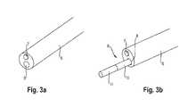
- the endoscope-like implanting instrumentcomprises an endoscope or endoscope shaft 6 having a proximal end portion (not shown) with an actuation handle and a distal end at which an optic 7 preferably comprising a lens system and/or a light sensitive chip (CMOS or CCD chip) is located.
- an optic 7preferably comprising a lens system and/or a light sensitive chip (CMOS or CCD chip) is located.
- a surgical instrumentfor example a tissue grasping means 10, 11 is supported such that is can be manually actuated at the proximal handle at least for moving/shifting along the working channel 8,
- the surgical instrumenthas a distal end effector 11, for example a hook, a needle or a forceps, which is operateably connected to an instrument shaft or cable 10 capable of transmitting actuating forces from the handle to the end effector 11.
- an adapter piece (cap fixation) 5 in the form of a bushing or sleeveis fixedly (integrally) connected or mounted with the endoscope shaft 6 wherein at the distal end of the adapter piece 5 and an expanding sleeve 4 is placed/formed.
- the expanding sleeve 4has an outer circumferencial surface adapted to spread a tissue clip 1 (as known from the prior art) when it will be slipped onto the expanding sleeve 4.
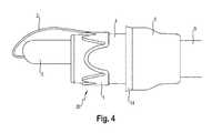
- Fig. 4the endoscope-like inserting or implanting instrument in a fully mounted state is shown. Accordingly, the tissue clip 1 is already slipped onto the expanding sleeve 4 such that it has its clip mouth elastically opened wherein a shifting ring 14 is located between the adapter piece 5 and the tissue clip 1.
- the shifting ring 14is moveably supported on the expanding sleeve 4 and is coupled with a withdrawing thread or string (not shown in the drawings but well known in the prior art) entering the expanding sleeve 4 and the working channel 8 or a specific feeding channel (not shown) parallel to the working channel 8, feeding the withdrawing thread to the proximal handle.
- the expanding sleeve 4is equipped with a clamping means 12, 13 comprising an open ring or a longitudinally slit bushing 12 which is located inside the expanding sleeve 4 axially in front of (distal to) the opening of the working channel 8.
- the open ring 12is positioned such that a predetermined axial distance between the open ring 12 and the distal end side (having the opening of the working channel 8) of the endoscope shaft 6 is maintained.
- the open ring 12is orientated such that the ring gap of the open ring 12 is positioned in front of (close to) the optic 7, such that the front view of the optic 7 will be not or only minimally affected by the open ring 12.
- the open ring 12is located substantially axial or co-axial in front of the working channel 8 wherein the ring gap is directed to the optical axis of the optic 7.
- an implant position means in the form of two radial projections 13are formed defining an axial end position for an implant when being clipped in the clamping means.
- the above implant of the present embodimentis a capsuled blood detection device 3 of a well known design having a cartridge-like casing with an outer circumferential diameter larger than the inner diameter of the open ring 12 such that when being clipped inside the ring 12 as shown in Fig. 6b the open ring 12 (or its ring arms) get elastically widened so that a predetermined clamping force is applied to the capsuled device 3.
- the capsuled device 3is connected with the tissue clip 1 by a connection thread or string 2 as shown in Fig. 4 .
- the implantis a metering capsule or just a tablet for successiveively supplying a drug to the patient's organ.
- FIG. 4shows the inventive implanting instrument in a fully mounted state.
- the tissue clip 1is slipped onto the expanding sleeve wherein the capsule-like device 3 being interconnected with the clip 1 by the connection thread 2 is clamped by the open ring (clamping means) 12.
- the implant positioning means 13provide an axial end stopper for the implant 3 such that the implant 3 is held by the open ring 12 in front of (distal) the working channel 8 without entering the working channel 8.
- the implanting instrumentis ready to get inserted into a hollow organ of a patient. Because the implant 3 is shielded by the surrounding expanding sleeve 4 the insertion movement of the implanting instrument can smoothly be done without the risk of loosing the implant 3.
- the surgical instrument 10, 11is actuated by forward shifting.
- the surgical instrument 10, 11, for example a tissue gripping meansis shifted outward of the working channel 8 it hits the capsuled device 3 being clipped in the open ring 12. Because the central axis of the ring 12 is axial or at least co-axial with the working channel 8 at its distal end portion the surgical instrument 10, 11 easily starts to shift the capsuled device 3 out of the ring 12 as it is shown in Fig. 7 .
- the withdrawing thread (not shown) for actuating the tissue clip 1is pulled at the proximal end of the endoscope shaft 6 so that the pushing ring 14 is pulled forward in the direction to the tissue clip 1.
- the tissue clip 1gets slowly moved forward until it slips off the expanding sleeve 4 to grasp tissue of the hollow organ and to fix the capsuled implant 3 at the selected position.
Landscapes
- Health & Medical Sciences (AREA)
- Life Sciences & Earth Sciences (AREA)
- Surgery (AREA)
- Molecular Biology (AREA)
- General Health & Medical Sciences (AREA)
- Veterinary Medicine (AREA)
- Engineering & Computer Science (AREA)
- Biomedical Technology (AREA)
- Heart & Thoracic Surgery (AREA)
- Medical Informatics (AREA)
- Public Health (AREA)
- Animal Behavior & Ethology (AREA)
- Physics & Mathematics (AREA)
- Biophysics (AREA)
- Pathology (AREA)
- Nuclear Medicine, Radiotherapy & Molecular Imaging (AREA)
- Reproductive Health (AREA)
- Vascular Medicine (AREA)
- Cardiology (AREA)
- Physiology (AREA)
- Surgical Instruments (AREA)
Abstract
Description
- The present invention relates to an apparatus or instrument for at least temporarily implanting of capsule-like metering, diagnose and/or monitoring devices, for example blood detection devices or the like preferably in hollow organs of a human or animal body using a tissue clip.
- From the state of the art, for instance according to
US 6,849,078 B2 , a tissue clip of this species is generally known as regards its basic design. For a better comprehension, this tissue clip is described hereinafter in detail with reference toFig. 1 . - Accordingly, such a
clip 100 consists of a mouth-type clamping means having twotoothed jaws lateral hinges 130 or by flexible moldings. Thehinges 130 or the flexible moldings are preferably formed of spring-elastic straps which during opening thejaws jaws jaws hinges 130 or the flexible moldings are actuated. - In detail, each
clip 100 is punched in one piece out of a spring steel sheet by working a ring having a partially different ring width out of the spring steel sheet. Two diametrally opposed ring portions having a large ring width constitute the twojaws hinges 130 or the flexible moldings. Thejaws - The functioning of the afore-described
medical tissue clip 100 can be described as follows: - In general, an endoscopic implantation of a medical device in total constitutes the most tolerable process for the patient. In this case the medical device must be fixed from the inside of a hollow organ to the latter. For this purpose, a number of the afore-described tissue cleats, clips or anchors are inserted into the hollow organ by means of an endoscope and are positioned at predetermined positions at the inner face of the organ. To this end, the respective clip or anchor is brought close to the organ tissue and the biasing spring is released for snapping of the clip or clamping of the anchor. The latter then clamps or holds a tissue fold between its jaws or its hooks or needles at a predetermined clamping or expanding force, wherein the teeth, hooks, needles or jags of each jaw cut into the tissue and preferably penetrate the same. In this way the clips or anchors are anchored to the inner face of the organ at predetermined spaces and thus form introducing points into the organ tissue for a tensile force.
- The endoscope not shown in detail in
Fig. 1 usually is equipped with an endoscope head or an endoscope cap which includes, apart from the functions generally required for an endoscope such as lighting, optical system and rinsing means, if necessary, in addition a holding and withdrawing means for the tissue clip. This holding and withdrawing means substantially consists of an expanding sleeve as well as a slide operable manually or by remote control which is movable in the longitudinal direction of the endoscope. The expanding sleeve is configured such that the already opened tissue clip can be attached to the sleeve in such manner that the clip can be prevented from slipping backwards while being inserted into the hollow organ. For this purpose, the slide is positioned axially behind the clip and serves so-to-speak as an axial stop for the clip. - As soon as the clip is to be positioned at a particular site, the slide is moved axially forward and in so doing strips off the clip over the expanding sleeve. Accordingly, the clip is actuated, i.e. the biasing mechanism within the clip described before by way of
Figure 1 is released when the latter is stripped off the expanding sleeve and the two jaws of the tissue clip snap to close while clamping the tissue provided there between. - Besides, for example the reference
US 2008/0097182 A1 discloses a device for hemorrhage detection being adapted to ensure a continuous monitoring of bleeding within a hollow organ of a human patient which device uses a tissue clip according to the above description for fixing the device at the inner wall of the hollow organ. The known device will be described in the following text portion with reference toFig. 9 . - As may be gathered from
Fig. 9 the device for hemorrhage detection is basically composed of an intracorporeal part and an extracorporeal part. Hereinafter, the intracorporeal part shall be described first. The intracorporeal part comprises afixing member 202, which is a clip or anchor in this embodiment and which is mounted to an inner wall of the hollow organ, the digestive tract in this embodiment. A detecting means 203 is connected to theclip 202 via a connectingmember 218, e.g. a cord or the like. In this embodiment, the detecting means 203 is composed of two light sources, one of which emits light in the UV range, and the other emits light in the red range of the visible spectrum, and a photosensitive sensor, such as a photodiode or a phototransistor. In a pulsed manner or successively, the light sources emit light into the interior of the hollow organ in which the light is absorbed and reflected, and the photosensitive sensor detects the light transmitted or reflected in the interior. The fixing means 202 can be formed as a stent-like structure or as a clip according to the above description. In this embodiment, the fixing means 202 is adapted to mount/fix the detecting means 203 in a tubular hollow organ, e.g. in the duodenum, for monitoring diffuse bleeding sources in the stomach or in the esophagus. The connectingmember 218 for connecting the detecting means 203 to thefixing member 202 may be formed as a cord, a wire or the like. In an embodiment, the connectingmember 218 is adapted to be made of a decomposing material, e.g. a biodegradable material, which decomposes gradually. Depending on the organ and the application, the decomposition time is set such that the connectingmember 218 separates thefixing member 202 from the detecting means 203 only after, preferably directly after, a reasonable observation time has elapsed. This measure permits the detecting means 203 to be excreted naturally through the digestive tract, separately from thefixing member 202. Thedetecting means 203 is connected to a transmittingunit 217 by means of a data transmitting cable, so that signals are transmissible between the photosensitive sensor and the transmittingunit 217. Alternatively, the detecting means may be anchored in the transmittingunit 217 or may be unitarily formed therewith. The transmittingunit 217 is basically composed of adata processing unit 204, an analog-digital converter 205, an energy source 206, e.g. a battery, and atransmitter 207. Thedata processing unit 204 controls the detecting means 203, the analog-digital converter 205 and thetransmitter 207, and evaluates the data received by the photosensitive sensor. The analog-digital converter 205 converts the analog signals sent by the detecting means 203 into digital signals, and thetransmitter 207 forwards the data evaluated by thedata processing unit 204 to areceiving unit 209. The data transmitted by thetransmitter 207 may be e.g. measured values, status information or event signals, e.g. the event of the occurrence of a bleeding. In this embodiment, the transmittingunit 217 is surrounded by anencapsulation 208, in order to protect the elements of the transmittingunit 217. In one example, the encapsulation is formed of a body-compatible material. The extracorporeal part is basically composed of areceiving unit 209, aninterface 210, and anevaluation unit 211. Thereceiving unit 209 receives data sent by thetransmitter 207 via a wireless trasmission. The data reveived by the receiving unit in this way are adapted to be evaluated or respresented in an evaluatingunit 211 may e.g. be an optical device or an acoustic signaling device, such as a display or a loudspeaker. Furthermore, the data received by the receiving unit are transmissible by means of theinterface 210 to third parties, e.g. a doctor or an emergency hotline/center. Hereinafter, the function of the device for hemorhage detection shall now be described. The intracorporeal part composed ofanchor 202, detecting means 203 and transmittingunit 217 is introduced into the digestive tract by means of an endoscope. There, theanchor 202 is fixed to an inner wall of the digestive tract by means of the endoscope. Thus, the detecting means 203 and the transmittingunit 217 are fixed in the interior of the digestive tract by theanchor 202. There, the detecting means 203 detects whether there is any blood in the digestive tract, or not. This works as follows: the two light sources of the detecting means 203, which emit light at a predetermined wavelength, are controlled by the receivingunit 204 such taht each light source emits light successively, the one light source emits light in the UV range, and the other light source emits light in the red range of the visible spectrum. The light emitted by the light sources emerges into the interior of the digestive tract, and is absorbed or reflected by the contents in the interior. The photosensitive sensor in the form of a photodiode or phototransistor, formed in thedetecting means 203, detects the light transmitted or reflected in the interior of the digestive tract, and produces a sensor signal on the basis of the detected light. Thus, one sensor signal is generated for each light source. If there is any blood in the interior of the digestive tract, the light emitted by the light sources in absorbed differently, as if there is no blood in the digestive tract, since blood has a specific characteristic absorption spectrum that iffers from the absorption spectrum of the "normal" organ contents. Accordingly, the light reflected in the interior and received by the photosensitive sensor dependence on the presence of blood in the interior of the organ and, accordingly, also the sensor signals that are sent our by the photosensitive sensor are different depending on the presence or absence of blood. Thus, due to the different sensor signals of the photosensitive sensor, the presence or absence of blood may be detected. - In praxis, it turned out, that especially the insertion action of a capsule-like device of this kind into the hollow organ using an endoscopic instrument creates problems in so far as, on the one hand, the capsule-like device has to be held inside the endoscopic instrument such it will not unintentionally be striped off when being inserted into the hollow organ. On the other hand, however, for a smooth positioning action at the inner wall of the hollow organ the capsule-like device has to be disconnected from the endoscopic device in a simple manner wherein the function of the above-mentioned clip and of the endoscopic device itself should not be affected.
- For example, the
WO 2011/066431 discloses a wireless capsule-like device being endoscopically anchored to the bowel wall using an endoscopic clip. In this implementation, the capsule-like device is designed to be integral part of the endoscopic clip with a minimum dimension on the 3 mm-scale in order to be introduced through the working channel of an endoscope into the hollow organ of the body. - A technical drawback of this solution is that the form factor is not compatible with currently commercially available battery technology, as the smallest button cell available has an outer diameter of 4,8 mm (e.g. Energize Type 337). Furthermore, it is known that for telemetric data transmission the antenna configuration inside the capsule-like device benefits from being surrounded by isolating material such as a plastic mould creating a distance to electrolytes such as biological tissue. In other words, an implementation of the capsule-like device in which the antenna is physically close to biological tissue surrounding the capsule-like device leads to significant damping effects on the electromagnetic waves being emitted from the antenna. Thus, for an appropriate signal strength outside the body, high output power may be necessary, which on the other hand may lead to undesired effects on the surrounding tissue.
- For this reason, capsule-like wireless devices for monitoring of parameters such as the detection of bleeding, an embodiment with minimum outer dimensions in the range of at least 5 mm is technologically advantageous. However, the implantation through the working channel of an endoscope, which is usually in the 3 mm range, is not possible. On the other hand, with endoscopic delivery devices such as the AdvanCE delivery device by US Endoscopy, Ohio, USA, it is possible to deliver capsule-like devices with outer diameter in the range of at least 5 mm into a hollow organ of the body. These type of devices, however, do not have the capability of anchoring the capsule-like device to the wall of the hollow organ.
- An integral endoscopic implanting apparatus which offers both the possibility of safe and easy introduction as well as secure anchoring of the capsule-like device of this kind is not known at present.
- For this reason, it is an object of the present invention, to provide an implanting apparatus or instrument for at least temporarily implanting a capsule-like device using a clip as a fixing means, wherein said implanting apparatus or instrument allows a safe insertion of the capsule-like device into a hollow organ of, for example, a human patient and a smooth disconnection of the capsule-like device when the clip gets fixed at the hollow organ.
- This object is solved by an implanting apparatus or instrument having the technical features according to the patent claim 1. Further advantageous configurations of the invention are the subject matter of the sub claims.
- Accordingly, the endoscope-like implanting instrument of the present invention has an endoscope cap comprising a holding and withdrawing means for a tissue clip especially in accordance with the above description being slipped onto an expanding sleeve of the endoscope cap. Furthermore, the endoscope cap has a (manual) clip actuating means for slipping the tissue clip off the expanding sleeve. The actuating means may comprise a front groove-like opening at the front edge of the expanding sleeve slitting open the cap sheath wall on both sides (or in other words, the front groove opens to both sides in circumferential direction at the outer circumference of the expanding sleeve thereby forming a tongue-like axial projection), as well as a withdrawing thread or string radially crossing the front groove-like opening at an axial front cap portion substantially in radial direction and being fixedly connected to the tongue-like projection at its one end and being movably introduced or adapted to be introduced into an endoscope channel forming a working channel or being separate to a working channel of the instrument for manually operating the same at a radial inner face of the endoscope cap.
- Therefore, in case a clip is slipped onto the expanding sleeve and enters the gap between the sleeve wall and the tongue-like projection the crossing thread or string will be pulled by the clip getting a curved elongation within the gap. If the thread or spring is now manually actuated the curved elongation within the gap gets straigthened thereby slipping the clip off the expanding sleeve.
- Alternative to the fixation of the thread or spring at the tongue-like projection, the thread or string might be connected at its distal end to a pushing ring, moveably/shiftably supported on the expanding sleeve (having no tongue-like axial projection) such that when the thread or string is manually actuated (pulled) the radial outer pushing ring is pulled along the expanding cap in direction to the distal end portion thereof, thereby slipping the clip (being in front of the pushing ring) off the expanding cap. Besides it is also possible to provide a pushing bar or pushing cable within the working channel or a separte functional channel which is connected at its distal end with the pushing sleeve or ring to apply a pushing force thereto for shifting the clip off the expandng cap.
- Finally, the endoscope-like implanting instrument is adapted to receive or comprises a surgical instrument being shiftable fed within the working channel of the implanting instrument, for example a tissue grasping means being moveably or shiftably inserted into the working channel for manually grasping and drawing the tissue of the hollow organ inside the endoscope cap, to bring and hold it in a position such that the tissue clip can be brought into clamping connection with the tissue when the clip is slipped off the expanding sleeve.
- According to the invention, the implanting instrument additionally has a holding means, especially a clamping means integrally arranged inside the endoscope cap, especially inside the expansion or expanding sleeve in an axial (distal) extension to the working channel (that means, axially in front of the working channel), such that the holding or clamping means being located axially in front of the working channel with an axial distance between the holding/clamping means and the distal opening of the working channnel. The holding/clamping means holds (or is adapted to hold) a capsule-like device such as a metering (for example a drug delivery means), diagnose and/or monitoring device, for example a blood detection device according to the above description being connected with the tissue clip especially of the above-mentioned design via a thread, band or string such that the capsule-like device will be automatically detached from the clamping means directly or indirectly by the surgical instrument, for example the grasping means when being manually actuated, for example for tissue grasping. This means, that a separate tool for detaching the capsule-like device (besides the surgical instrument) is not needed. Furthermore, directly and indirectly means that the surgical instrument may directly contact the capsule-like device or will contact a kind of a fireing means like a lever system or a spring to fire the capsule-like device.
- Because, according to one aspect of the invention, the holding/clamping means is located inside the expanding sleeve, the capsule-like device attached thereto is protected by the expanding sleeve when being inserted into the hollow organ. Additionally, because according to another aspect of the invention the clamping means is located in front of the working channel with a predetermined axial distance there between the capsule-like device does not need to enter the working channel when being clamped so that the working channel is not needed to get radial enlarged. Therefore, the function of the surgical instrument, for example the grasping means can be maintained.
- The clamping means according to a further aspect of the invention is dimensioned such that the clamping force applied to the capsule-like device is high enough to safely hold the capsule-like device when it is (will be) inserted/shifted into the hollow organ. The clamping force, however, is weak enough to allow a disconnection of the capsule-like device from the clamping means by the surgical instrument, for example the grasping means in case the surgical instrument is shifted forward into the distal direction of the implanting instrument. Therefore, the surgical instrument, especially the grasping means generally in the form of a bit hook, needle or the like, connected to a pushing cable/rod fed inside the working channel is not needed to get additionally enforced to achieve a sufficient pushing force onto the capsule-like device for its disconnection.
- In order to enhance this disconnection action, the clamping means according to another aspect of the invention is designed such that its disconnection direction is axial or co-axial to the shifting direction of the surgical instrument. Therefore, in case the surgical instrument is shifted forward out of the working channel it automatically contacts the capsule-like device for pushing it out of the clamping means.
- According to a further aspect of the invention, the clamping means is designed as a ring having a specific elasticity to get radial expanded when the capsule is inserted, thereby applying a predetermined radial clamping force onto the capsule-like device. To improve the elastic character of the clamping means the ring is not formed as a closed but as an open ring having two arc-shaped arms forming a ring gap there between. Here, it has to be pointed out, that the implanting device is equipped with an optic having a lens system or a light sensitive chip at the distal end thereof inside the expanding sleeve/endoscope cap. According to another aspect of the invention, the above open ring is orientated such that the ring gap is substantially in front of the optic to allow a free view to the distal direction of the instrument.
- According to a further aspect of the present invention the clamping means is integrally connected to the endoscope cap/expanding sleeve, for example by resin molding, gluing, melting or the like, and can be made of the same or different material with respect to the expanding sleeve. The interconnection between the clamping means in the form of an open ring and the expanding sleeve is substantially point- or line-shaped along a predetermined distance in circumferential direction such that the elastic movement of the free two ring arms and the clamping force exclusively generated by the ring arms are not affected.
- Finally, it shall be clarified that the above aspects can be claimed separately as being individual solutions of the cited object but also in combination with each other in accordance with the enclosed claim combinations.
- Hereinafter the invention is explained in detail by way of a preferred embodiment with reference to the accompanying drawings, in which
Fig. 1 shows the exemplary design of a tissue clip as it is known already from the state of the art and as it is equally employed in the present invention,Fig. 2 illustrates an exploded view of an capsule-like device (especially a blood detecting capsule) being interconnected with a tissue clip by a thread or string, an expansion cap and an connection adapter of an endoscope-like instrument,Fig. 3a and 3b show the distal end portion of the endoscope-like instrument comprising at least a working channel feeding a surgical instrument having an instrument end effector especially a grasping means for tissue grasping and an optic, like a lens-system and/or a photosensitive chip,Fig. 4 illustrates the endoscope-like implanting instrument in a fully mounted state for getting inserted into a hollow organ, comprising the endoscope and the expansion cap carrying the tissue clip and the capsule-like device,Fig. 5a and 5b show the front view of the expanding cap having the clamping means for holding the capsule-like device also in relation with the working channel and the optic of the endoscope,Fig. 6a and 6b show a perspective view of the expanding cap without and with the capsule-like device held by the clamping meansFig. 7 shows the expanding cap with the surgical instrument (grasping means) being ascended from the working channel,Fig. 8 illustrates a longitudinal cross section of the expanding cap andFig. 9 illustrates in principle a blood detection system comprising a blood detecting capsule as can be used in the present implanting instrument.- According to
Fig. 2 ,3a to 3b the endoscope-like implanting instrument according to a preferred embodiment of the invention comprises an endoscope orendoscope shaft 6 having a proximal end portion (not shown) with an actuation handle and a distal end at which anoptic 7 preferably comprising a lens system and/or a light sensitive chip (CMOS or CCD chip) is located. Inside theendoscope shaft 6 at least one working channel 8 is formed in which a surgical instrument, for example a tissue grasping means 10, 11 is supported such that is can be manually actuated at the proximal handle at least for moving/shifting along the working channel 8, The surgical instrument has adistal end effector 11, for example a hook, a needle or a forceps, which is operateably connected to an instrument shaft orcable 10 capable of transmitting actuating forces from the handle to theend effector 11. - At the distal end of the
endosope shaft 6 an adapter piece (cap fixation) 5 in the form of a bushing or sleeve is fixedly (integrally) connected or mounted with theendoscope shaft 6 wherein at the distal end of theadapter piece 5 and an expanding sleeve 4 is placed/formed. The expanding sleeve 4 has an outer circumferencial surface adapted to spread a tissue clip 1 (as known from the prior art) when it will be slipped onto the expanding sleeve 4. - For example, in
Fig. 4 the endoscope-like inserting or implanting instrument in a fully mounted state is shown. Accordingly, the tissue clip 1 is already slipped onto the expanding sleeve 4 such that it has its clip mouth elastically opened wherein a shiftingring 14 is located between theadapter piece 5 and the tissue clip 1. The shiftingring 14 is moveably supported on the expanding sleeve 4 and is coupled with a withdrawing thread or string (not shown in the drawings but well known in the prior art) entering the expanding sleeve 4 and the working channel 8 or a specific feeding channel (not shown) parallel to the working channel 8, feeding the withdrawing thread to the proximal handle. - As can be seen in the
Fig. 5a, 5b ,6a, 6b and7 the expanding sleeve 4 is equipped with a clamping means 12, 13 comprising an open ring or a longitudinally slit bushing 12 which is located inside the expanding sleeve 4 axially in front of (distal to) the opening of the working channel 8. As shown especially inFig. 6a , theopen ring 12 is positioned such that a predetermined axial distance between theopen ring 12 and the distal end side (having the opening of the working channel 8) of theendoscope shaft 6 is maintained. Furthermore, theopen ring 12 is orientated such that the ring gap of theopen ring 12 is positioned in front of (close to) theoptic 7, such that the front view of theoptic 7 will be not or only minimally affected by theopen ring 12. In other words, theopen ring 12 is located substantially axial or co-axial in front of the working channel 8 wherein the ring gap is directed to the optical axis of theoptic 7. Finally, within the axial distance between thering 12 and the distal end side of theendoscope shaft 6 an implant position means in the form of two radial projections 13 (seeFig. 6a and8 ) are formed defining an axial end position for an implant when being clipped in the clamping means. - According to
Fig. 2 the above implant of the present embodiment is a capsuled blood detection device 3 of a well known design having a cartridge-like casing with an outer circumferential diameter larger than the inner diameter of theopen ring 12 such that when being clipped inside thering 12 as shown inFig. 6b the open ring 12 (or its ring arms) get elastically widened so that a predetermined clamping force is applied to the capsuled device 3. The capsuled device 3 is connected with the tissue clip 1 by a connection thread orstring 2 as shown inFig. 4 . However it is also possible that the implant is a metering capsule or just a tablet for succesively supplying a drug to the patient's organ. - The function of the endoscope-like implanting instrument having the above basic design will be described in the following:
- As already stated above,
Fig. 4 shows the inventive implanting instrument in a fully mounted state. Here, the tissue clip 1 is slipped onto the expanding sleeve wherein the capsule-like device 3 being interconnected with the clip 1 by theconnection thread 2 is clamped by the open ring (clamping means) 12. As can be best seen inFig. 6b , the implant positioning means 13 provide an axial end stopper for the implant 3 such that the implant 3 is held by theopen ring 12 in front of (distal) the working channel 8 without entering the working channel 8. In this mounting state the implanting instrument is ready to get inserted into a hollow organ of a patient. Because the implant 3 is shielded by the surrounding expanding sleeve 4 the insertion movement of the implanting instrument can smoothly be done without the risk of loosing the implant 3. - In case the implanting instrument has reached its end position within the hollow organ the
surgical instrument surgical instrument open ring 12. Because the central axis of thering 12 is axial or at least co-axial with the working channel 8 at its distal end portion thesurgical instrument ring 12 as it is shown inFig. 7 . - Finally, the withdrawing thread (not shown) for actuating the tissue clip 1 is pulled at the proximal end of the
endoscope shaft 6 so that the pushingring 14 is pulled forward in the direction to the tissue clip 1. Thereby the tissue clip 1 gets slowly moved forward until it slips off the expanding sleeve 4 to grasp tissue of the hollow organ and to fix the capsuled implant 3 at the selected position.
Claims (11)
- An endoscope-like implanting instrument having an endoscope cap unit (20) holding and withdrawing a tissue clip (1) slipped onto an expanding sleeve (4) of the endoscope cap unit (20), said endoscope cap unit (20) comprises for this purpose a clip actuating means for slipping the tissue clip (1) off the expanding sleeve (4) said clip actuating means has a withdrawing thread or string or a pushing bar or pushing cable being movably introduced or adapted to be introduced into an endoscope channel forming a working channel (8) or being separate to the working channel (8) of the endoscope-like implanting instrument for manually operating the clip actuating means at a proximal end portion of the endoscope-like implanting instrument to slip off the tissue clip (1) from the expanding sleeve (4) wherein said endoscope-like implanting instrument is adapted to receive a surgical instrument (10, 11) preferably a tissue grasping means being shiftably inserted into the working channel (8) for axially deploying from the distal end of the working channel (8) when getting manually actuated,characterized by
a holding or clamping means (12) integrally arranged inside the endoscope cap unit (20) preferably the expanding sleeve (4) in front of, preferably in axial extension to the working channel (8), holding a capsule-like device (3) being connected with the tissue clip (1) via a connection thread, band or string (2) such that the capsule-like device (3) will be automatically detached directly or indirectly by said surgical instrument (10, 11) when being manually actuated. - An endoscope-like implanting instrument according to claim 1characterized in that said clamping means (12) is arranged inside the endoscope cap unit (20) preferably the expanding sleeve (3) such that the clamping means (12) is located axially in front of the working channel (8) or its distal opening with an axial distance there between.
- An endoscope-like implanting instrument according to one of the claims 1 and 2characterized in that said capsule-like device (3) is a metering, diagnose and/or monitoring device, especially a blood detection device.
- An endoscope-like implanting instrument according to one of the above claims,characterized in that said clamping means (12) is dimensioned such that the clamping force applied to the capsule-like device (3) is high enough to safely hold the capsule-like device when it is inserted into the hollow organ, but it is weak enough to allow a disconnection of the capsule-like device (3) from the clamping means (12) by the surgical instrument (10, 11) in case the surgical instrument (10, 11) is shifted forward into the distal direction of the endoscope-like implanting instrument.
- An endoscope-like implanting instrument according to one of the above claims,characterized in that said clamping means (12) is designed such that its disconnection direction is axial or co-axial to the shifting direction of the surgical instrument.
- An endoscope-like implanting instrument according to one of the above claims,characterized in that said clamping means (12) is designed as a ring having a specific elasticity to get radial expanded thereby applying a predetermined radial clamping force onto the capsule-like device (3).
- An endoscope-like implanting instrument according to claim 6,characterized in that said ring is formed as an open ring having two arc-shaped arms forming a ring gap there between.
- An endoscope-like implanting instrument according to claim 7,characterized in that the endoscope-like implanting device is equipped with an optic (7) having a lens system or a light sensitive chip at the distal end of the endoscope-like implanting device inside the endocope cap unit (20), preferably the expanding sleeve (4), wherein open ring is orientated such that the ring gap is substantially in front of the optic (7) to allow a free view to the distal direction of the endoscope-like implanting instrument.
- An endoscope-like implanting instrument according to one of the above claims,characterized in that said clamping means (12) is integrally connected with the endoscope cap unit (20), preferably the expanding sleeve (4) by resin molding, gluing, or melting and can be made of the same or different material with respect to the expanding sleeve (4).
- An endoscope-like implanting instrument according to one of the claims 8 and 9,characterized in that the interconnection between the clamping means (12) in the form of an open ring and the expanding sleeve (4) is substantially point- or line-shaped.
- An endoscope-like implanting instrument according to one of the above claims,characterized in that said surgical instrument (10, 11) forms an exchangeable and/or freely selectable part of the endoscope-like implanting instrument.
Priority Applications (3)
| Application Number | Priority Date | Filing Date | Title |
|---|---|---|---|
| EP20110190135EP2596756B1 (en) | 2011-11-22 | 2011-11-22 | Implanting apparatus |
| US13/682,025US9138227B2 (en) | 2011-11-22 | 2012-11-20 | Implanting apparatus |
| JP2012254377AJP5833997B2 (en) | 2011-11-22 | 2012-11-20 | Implanting device |
Applications Claiming Priority (1)
| Application Number | Priority Date | Filing Date | Title |
|---|---|---|---|
| EP20110190135EP2596756B1 (en) | 2011-11-22 | 2011-11-22 | Implanting apparatus |
Publications (2)
| Publication Number | Publication Date |
|---|---|
| EP2596756A1true EP2596756A1 (en) | 2013-05-29 |
| EP2596756B1 EP2596756B1 (en) | 2014-02-26 |
Family
ID=45023722
Family Applications (1)
| Application Number | Title | Priority Date | Filing Date |
|---|---|---|---|
| EP20110190135ActiveEP2596756B1 (en) | 2011-11-22 | 2011-11-22 | Implanting apparatus |
Country Status (3)
| Country | Link |
|---|---|
| US (1) | US9138227B2 (en) |
| EP (1) | EP2596756B1 (en) |
| JP (1) | JP5833997B2 (en) |
Cited By (31)
| Publication number | Priority date | Publication date | Assignee | Title |
|---|---|---|---|---|
| US8926502B2 (en) | 2011-03-07 | 2015-01-06 | Endochoice, Inc. | Multi camera endoscope having a side service channel |
| US9101266B2 (en) | 2011-02-07 | 2015-08-11 | Endochoice Innovation Center Ltd. | Multi-element cover for a multi-camera endoscope |
| US9101287B2 (en) | 2011-03-07 | 2015-08-11 | Endochoice Innovation Center Ltd. | Multi camera endoscope assembly having multiple working channels |
| US9101268B2 (en) | 2009-06-18 | 2015-08-11 | Endochoice Innovation Center Ltd. | Multi-camera endoscope |
| US9314147B2 (en) | 2011-12-13 | 2016-04-19 | Endochoice Innovation Center Ltd. | Rotatable connector for an endoscope |
| US9320419B2 (en) | 2010-12-09 | 2016-04-26 | Endochoice Innovation Center Ltd. | Fluid channeling component of a multi-camera endoscope |
| US9402533B2 (en) | 2011-03-07 | 2016-08-02 | Endochoice Innovation Center Ltd. | Endoscope circuit board assembly |
| US9492063B2 (en) | 2009-06-18 | 2016-11-15 | Endochoice Innovation Center Ltd. | Multi-viewing element endoscope |
| US9554692B2 (en) | 2009-06-18 | 2017-01-31 | EndoChoice Innovation Ctr. Ltd. | Multi-camera endoscope |
| US9560954B2 (en) | 2012-07-24 | 2017-02-07 | Endochoice, Inc. | Connector for use with endoscope |
| US9560953B2 (en) | 2010-09-20 | 2017-02-07 | Endochoice, Inc. | Operational interface in a multi-viewing element endoscope |
| US9642513B2 (en) | 2009-06-18 | 2017-05-09 | Endochoice Inc. | Compact multi-viewing element endoscope system |
| US9655502B2 (en) | 2011-12-13 | 2017-05-23 | EndoChoice Innovation Center, Ltd. | Removable tip endoscope |
| US9706903B2 (en) | 2009-06-18 | 2017-07-18 | Endochoice, Inc. | Multiple viewing elements endoscope system with modular imaging units |
| US9713417B2 (en) | 2009-06-18 | 2017-07-25 | Endochoice, Inc. | Image capture assembly for use in a multi-viewing elements endoscope |
| US9814374B2 (en) | 2010-12-09 | 2017-11-14 | Endochoice Innovation Center Ltd. | Flexible electronic circuit board for a multi-camera endoscope |
| US9872609B2 (en) | 2009-06-18 | 2018-01-23 | Endochoice Innovation Center Ltd. | Multi-camera endoscope |
| US9901244B2 (en) | 2009-06-18 | 2018-02-27 | Endochoice, Inc. | Circuit board assembly of a multiple viewing elements endoscope |
| US9986899B2 (en) | 2013-03-28 | 2018-06-05 | Endochoice, Inc. | Manifold for a multiple viewing elements endoscope |
| US9993142B2 (en) | 2013-03-28 | 2018-06-12 | Endochoice, Inc. | Fluid distribution device for a multiple viewing elements endoscope |
| US10080486B2 (en) | 2010-09-20 | 2018-09-25 | Endochoice Innovation Center Ltd. | Multi-camera endoscope having fluid channels |
| US10165929B2 (en) | 2009-06-18 | 2019-01-01 | Endochoice, Inc. | Compact multi-viewing element endoscope system |
| US10203493B2 (en) | 2010-10-28 | 2019-02-12 | Endochoice Innovation Center Ltd. | Optical systems for multi-sensor endoscopes |
| US10499794B2 (en) | 2013-05-09 | 2019-12-10 | Endochoice, Inc. | Operational interface in a multi-viewing element endoscope |
| US11278190B2 (en) | 2009-06-18 | 2022-03-22 | Endochoice, Inc. | Multi-viewing element endoscope |
| US11547275B2 (en) | 2009-06-18 | 2023-01-10 | Endochoice, Inc. | Compact multi-viewing element endoscope system |
| US11864734B2 (en) | 2009-06-18 | 2024-01-09 | Endochoice, Inc. | Multi-camera endoscope |
| US11889986B2 (en) | 2010-12-09 | 2024-02-06 | Endochoice, Inc. | Flexible electronic circuit board for a multi-camera endoscope |
| US12137873B2 (en) | 2009-06-18 | 2024-11-12 | Endochoice, Inc. | Compact multi-viewing element endoscope system |
| US12204087B2 (en) | 2010-10-28 | 2025-01-21 | Endochoice, Inc. | Optical systems for multi-sensor endoscopes |
| US12220105B2 (en) | 2010-06-16 | 2025-02-11 | Endochoice, Inc. | Circuit board assembly of a multiple viewing elements endoscope |
Families Citing this family (6)
| Publication number | Priority date | Publication date | Assignee | Title |
|---|---|---|---|---|
| DE102017112896A1 (en)* | 2017-06-12 | 2018-12-13 | Ovesco Endoscopy Ag | Tissue clip application Ausrüst- / retrofit kit |
| US11413050B2 (en) | 2018-01-05 | 2022-08-16 | Theragi, LLC | Surgical clip and deployment system |
| US11779344B2 (en)* | 2020-09-30 | 2023-10-10 | Boston Scientific Scimed, Inc. | Repositionable closure device |
| WO2022094620A1 (en)* | 2020-11-02 | 2022-05-05 | Boston Scientific Scimed, Inc. | Medical systems, devices, and related methods |
| CN112790805B (en)* | 2021-01-28 | 2025-03-04 | 江苏唯德康医疗科技有限公司 | Anastomotic clip removal kit |
| EP4362820A1 (en) | 2022-01-14 | 2024-05-08 | Boston Scientific Medical Device Limited | Steerable platform repositionable over the scope clip |
Citations (6)
| Publication number | Priority date | Publication date | Assignee | Title |
|---|---|---|---|---|
| US6285897B1 (en)* | 1999-04-07 | 2001-09-04 | Endonetics, Inc. | Remote physiological monitoring system |
| US6849078B2 (en) | 1999-11-18 | 2005-02-01 | Ovesco Endoscopy, Gmbh | Apparatus and method for compressing body tissue |
| EP1902660A1 (en)* | 2005-07-14 | 2008-03-26 | Olympus Corporation | In vivo imaging device, display device, image display system using the devices, and system for indwelling in subject body |
| US20080097182A1 (en) | 2006-07-03 | 2008-04-24 | Novineon Healthcare Technology Partners, Gmbh | Device for hemorrhage detection |
| EP2163206A1 (en)* | 2008-09-16 | 2010-03-17 | Scuola Superiore di Studi Universitari e di Perfezionamento Sant'Anna | Surgical clip delivering wireless capsule |
| WO2011066431A2 (en) | 2009-11-25 | 2011-06-03 | Brigham And Women's Hospital, Inc. | System and method for wireless biosensor monitoring |
Family Cites Families (23)
| Publication number | Priority date | Publication date | Assignee | Title |
|---|---|---|---|---|
| US5297536A (en)* | 1992-08-25 | 1994-03-29 | Wilk Peter J | Method for use in intra-abdominal surgery |
| US5406418A (en)* | 1993-07-15 | 1995-04-11 | Precision Optics Corporation | Mechanical coupler for eyepieces |
| US7235089B1 (en)* | 1994-12-07 | 2007-06-26 | Boston Scientific Corporation | Surgical apparatus and method |
| US6632171B2 (en)* | 1997-12-22 | 2003-10-14 | Given Imaging Ltd. | Method for in vivo delivery of autonomous capsule |
| US6352503B1 (en)* | 1998-07-17 | 2002-03-05 | Olympus Optical Co., Ltd. | Endoscopic surgery apparatus |
| WO2000059376A1 (en)* | 1999-04-07 | 2000-10-12 | Endonetics, Inc. | Implantable monitoring probe |
| US6911032B2 (en)* | 1999-11-18 | 2005-06-28 | Scimed Life Systems, Inc. | Apparatus and method for compressing body tissue |
| US7993368B2 (en)* | 2003-03-13 | 2011-08-09 | C.R. Bard, Inc. | Suture clips, delivery devices and methods |
| AU6057801A (en)* | 2000-05-23 | 2001-12-03 | Given Imaging Ltd. | Device and method for positioning an object in a body lumen |
| US6754536B2 (en)* | 2001-01-31 | 2004-06-22 | Medtronic, Inc | Implantable medical device affixed internally within the gastrointestinal tract |
| US6535764B2 (en)* | 2001-05-01 | 2003-03-18 | Intrapace, Inc. | Gastric treatment and diagnosis device and method |
| US7689284B2 (en)* | 2001-05-01 | 2010-03-30 | Intrapace, Inc. | Pseudounipolar lead for stimulating a digestive organ |
| US20080065169A1 (en)* | 2001-05-01 | 2008-03-13 | Intrapace, Inc. | Endoscopic Instrument for Engaging a Device |
| JP3993550B2 (en)* | 2003-09-30 | 2007-10-17 | オリンパス株式会社 | Gastrointestinal inspection device |
| US20050165272A1 (en)* | 2003-12-01 | 2005-07-28 | Yuta Okada | Endoscope system |
| US20050240202A1 (en)* | 2004-04-21 | 2005-10-27 | Hani Shennib | Devices and methods of repairing cardiac valves |
| CN101217908B (en)* | 2005-07-08 | 2012-10-24 | 奥林巴斯医疗株式会社 | Apparatus for placing capsule type medical device, apparatus for placing capsule endoscope in the body |
| JP4665262B2 (en)* | 2005-08-31 | 2011-04-06 | 富士フイルム株式会社 | Endoscope hood |
| US20070203395A1 (en)* | 2006-02-28 | 2007-08-30 | Takayasu Mikkaichi | Cap installable on distal end portion of endoscope |
| WO2007131112A2 (en)* | 2006-05-03 | 2007-11-15 | Indiana University Research & Technology Corporation | Methods and apparatuses for reshaping the esophagus and other body lumens |
| DE202008007774U1 (en)* | 2008-06-11 | 2008-08-14 | Ovesco Endoscopy Gmbh | endoscope cap |
| DE102009050829B4 (en)* | 2009-10-27 | 2013-01-24 | Ovesco Endoscopy Ag | resection |
| DE102009051408A1 (en)* | 2009-10-30 | 2011-05-05 | Ovesco Endoscopy Ag | Medical instrument for setting tissue clips |
- 2011
- 2011-11-22EPEP20110190135patent/EP2596756B1/enactiveActive
- 2012
- 2012-11-20USUS13/682,025patent/US9138227B2/enactiveActive
- 2012-11-20JPJP2012254377Apatent/JP5833997B2/enactiveActive
Patent Citations (6)
| Publication number | Priority date | Publication date | Assignee | Title |
|---|---|---|---|---|
| US6285897B1 (en)* | 1999-04-07 | 2001-09-04 | Endonetics, Inc. | Remote physiological monitoring system |
| US6849078B2 (en) | 1999-11-18 | 2005-02-01 | Ovesco Endoscopy, Gmbh | Apparatus and method for compressing body tissue |
| EP1902660A1 (en)* | 2005-07-14 | 2008-03-26 | Olympus Corporation | In vivo imaging device, display device, image display system using the devices, and system for indwelling in subject body |
| US20080097182A1 (en) | 2006-07-03 | 2008-04-24 | Novineon Healthcare Technology Partners, Gmbh | Device for hemorrhage detection |
| EP2163206A1 (en)* | 2008-09-16 | 2010-03-17 | Scuola Superiore di Studi Universitari e di Perfezionamento Sant'Anna | Surgical clip delivering wireless capsule |
| WO2011066431A2 (en) | 2009-11-25 | 2011-06-03 | Brigham And Women's Hospital, Inc. | System and method for wireless biosensor monitoring |
Cited By (62)
| Publication number | Priority date | Publication date | Assignee | Title |
|---|---|---|---|---|
| US11471028B2 (en) | 2009-06-18 | 2022-10-18 | Endochoice, Inc. | Circuit board assembly of a multiple viewing elements endoscope |
| US11986155B2 (en) | 2009-06-18 | 2024-05-21 | Endochoice, Inc. | Multi-viewing element endoscope |
| US12336686B2 (en) | 2009-06-18 | 2025-06-24 | Endochoice, Inc. | Multi-viewing element endoscope |
| US9101268B2 (en) | 2009-06-18 | 2015-08-11 | Endochoice Innovation Center Ltd. | Multi-camera endoscope |
| US12303106B2 (en) | 2009-06-18 | 2025-05-20 | Endochoice, Inc. | Multi-camera endoscope |
| US12137873B2 (en) | 2009-06-18 | 2024-11-12 | Endochoice, Inc. | Compact multi-viewing element endoscope system |
| US11864734B2 (en) | 2009-06-18 | 2024-01-09 | Endochoice, Inc. | Multi-camera endoscope |
| US11547275B2 (en) | 2009-06-18 | 2023-01-10 | Endochoice, Inc. | Compact multi-viewing element endoscope system |
| US9492063B2 (en) | 2009-06-18 | 2016-11-15 | Endochoice Innovation Center Ltd. | Multi-viewing element endoscope |
| US9554692B2 (en) | 2009-06-18 | 2017-01-31 | EndoChoice Innovation Ctr. Ltd. | Multi-camera endoscope |
| US11534056B2 (en) | 2009-06-18 | 2022-12-27 | Endochoice, Inc. | Multi-camera endoscope |
| US11278190B2 (en) | 2009-06-18 | 2022-03-22 | Endochoice, Inc. | Multi-viewing element endoscope |
| US9642513B2 (en) | 2009-06-18 | 2017-05-09 | Endochoice Inc. | Compact multi-viewing element endoscope system |
| US10912445B2 (en) | 2009-06-18 | 2021-02-09 | Endochoice, Inc. | Compact multi-viewing element endoscope system |
| US9706905B2 (en) | 2009-06-18 | 2017-07-18 | Endochoice Innovation Center Ltd. | Multi-camera endoscope |
| US9706903B2 (en) | 2009-06-18 | 2017-07-18 | Endochoice, Inc. | Multiple viewing elements endoscope system with modular imaging units |
| US9713417B2 (en) | 2009-06-18 | 2017-07-25 | Endochoice, Inc. | Image capture assembly for use in a multi-viewing elements endoscope |
| US10905320B2 (en) | 2009-06-18 | 2021-02-02 | Endochoice, Inc. | Multi-camera endoscope |
| US10799095B2 (en) | 2009-06-18 | 2020-10-13 | Endochoice, Inc. | Multi-viewing element endoscope |
| US10791909B2 (en) | 2009-06-18 | 2020-10-06 | Endochoice, Inc. | Image capture assembly for use in a multi-viewing elements endoscope |
| US9872609B2 (en) | 2009-06-18 | 2018-01-23 | Endochoice Innovation Center Ltd. | Multi-camera endoscope |
| US9901244B2 (en) | 2009-06-18 | 2018-02-27 | Endochoice, Inc. | Circuit board assembly of a multiple viewing elements endoscope |
| US10638922B2 (en) | 2009-06-18 | 2020-05-05 | Endochoice, Inc. | Multi-camera endoscope |
| US10791910B2 (en) | 2009-06-18 | 2020-10-06 | Endochoice, Inc. | Multiple viewing elements endoscope system with modular imaging units |
| US10165929B2 (en) | 2009-06-18 | 2019-01-01 | Endochoice, Inc. | Compact multi-viewing element endoscope system |
| US10092167B2 (en) | 2009-06-18 | 2018-10-09 | Endochoice, Inc. | Multiple viewing elements endoscope system with modular imaging units |
| US12220105B2 (en) | 2010-06-16 | 2025-02-11 | Endochoice, Inc. | Circuit board assembly of a multiple viewing elements endoscope |
| US10080486B2 (en) | 2010-09-20 | 2018-09-25 | Endochoice Innovation Center Ltd. | Multi-camera endoscope having fluid channels |
| US9560953B2 (en) | 2010-09-20 | 2017-02-07 | Endochoice, Inc. | Operational interface in a multi-viewing element endoscope |
| US9986892B2 (en) | 2010-09-20 | 2018-06-05 | Endochoice, Inc. | Operational interface in a multi-viewing element endoscope |
| US11543646B2 (en) | 2010-10-28 | 2023-01-03 | Endochoice, Inc. | Optical systems for multi-sensor endoscopes |
| US12204087B2 (en) | 2010-10-28 | 2025-01-21 | Endochoice, Inc. | Optical systems for multi-sensor endoscopes |
| US10203493B2 (en) | 2010-10-28 | 2019-02-12 | Endochoice Innovation Center Ltd. | Optical systems for multi-sensor endoscopes |
| US11889986B2 (en) | 2010-12-09 | 2024-02-06 | Endochoice, Inc. | Flexible electronic circuit board for a multi-camera endoscope |
| US9320419B2 (en) | 2010-12-09 | 2016-04-26 | Endochoice Innovation Center Ltd. | Fluid channeling component of a multi-camera endoscope |
| US10182707B2 (en) | 2010-12-09 | 2019-01-22 | Endochoice Innovation Center Ltd. | Fluid channeling component of a multi-camera endoscope |
| US9814374B2 (en) | 2010-12-09 | 2017-11-14 | Endochoice Innovation Center Ltd. | Flexible electronic circuit board for a multi-camera endoscope |
| US10898063B2 (en) | 2010-12-09 | 2021-01-26 | Endochoice, Inc. | Flexible electronic circuit board for a multi camera endoscope |
| US11497388B2 (en) | 2010-12-09 | 2022-11-15 | Endochoice, Inc. | Flexible electronic circuit board for a multi-camera endoscope |
| US9351629B2 (en) | 2011-02-07 | 2016-05-31 | Endochoice Innovation Center Ltd. | Multi-element cover for a multi-camera endoscope |
| US9101266B2 (en) | 2011-02-07 | 2015-08-11 | Endochoice Innovation Center Ltd. | Multi-element cover for a multi-camera endoscope |
| US10070774B2 (en) | 2011-02-07 | 2018-09-11 | Endochoice Innovation Center Ltd. | Multi-element cover for a multi-camera endoscope |
| US9854959B2 (en) | 2011-03-07 | 2018-01-02 | Endochoice Innovation Center Ltd. | Multi camera endoscope assembly having multiple working channels |
| US9713415B2 (en) | 2011-03-07 | 2017-07-25 | Endochoice Innovation Center Ltd. | Multi camera endoscope having a side service channel |
| US9101287B2 (en) | 2011-03-07 | 2015-08-11 | Endochoice Innovation Center Ltd. | Multi camera endoscope assembly having multiple working channels |
| US10292578B2 (en) | 2011-03-07 | 2019-05-21 | Endochoice Innovation Center Ltd. | Multi camera endoscope assembly having multiple working channels |
| US9402533B2 (en) | 2011-03-07 | 2016-08-02 | Endochoice Innovation Center Ltd. | Endoscope circuit board assembly |
| US11026566B2 (en) | 2011-03-07 | 2021-06-08 | Endochoice, Inc. | Multi camera endoscope assembly having multiple working channels |
| US8926502B2 (en) | 2011-03-07 | 2015-01-06 | Endochoice, Inc. | Multi camera endoscope having a side service channel |
| US10470649B2 (en) | 2011-12-13 | 2019-11-12 | Endochoice, Inc. | Removable tip endoscope |
| US9655502B2 (en) | 2011-12-13 | 2017-05-23 | EndoChoice Innovation Center, Ltd. | Removable tip endoscope |
| US9314147B2 (en) | 2011-12-13 | 2016-04-19 | Endochoice Innovation Center Ltd. | Rotatable connector for an endoscope |
| US12290241B2 (en) | 2011-12-13 | 2025-05-06 | Endochoice, Inc. | Removable tip endoscope |
| US9560954B2 (en) | 2012-07-24 | 2017-02-07 | Endochoice, Inc. | Connector for use with endoscope |
| US11925323B2 (en) | 2013-03-28 | 2024-03-12 | Endochoice, Inc. | Fluid distribution device for a multiple viewing elements endoscope |
| US9986899B2 (en) | 2013-03-28 | 2018-06-05 | Endochoice, Inc. | Manifold for a multiple viewing elements endoscope |
| US9993142B2 (en) | 2013-03-28 | 2018-06-12 | Endochoice, Inc. | Fluid distribution device for a multiple viewing elements endoscope |
| US12232699B2 (en) | 2013-03-28 | 2025-02-25 | Endochoice, Inc. | Manifold for a multiple viewing elements endoscope |
| US11793393B2 (en) | 2013-03-28 | 2023-10-24 | Endochoice, Inc. | Manifold for a multiple viewing elements endoscope |
| US10925471B2 (en) | 2013-03-28 | 2021-02-23 | Endochoice, Inc. | Fluid distribution device for a multiple viewing elements endoscope |
| US10905315B2 (en) | 2013-03-28 | 2021-02-02 | Endochoice, Inc. | Manifold for a multiple viewing elements endoscope |
| US10499794B2 (en) | 2013-05-09 | 2019-12-10 | Endochoice, Inc. | Operational interface in a multi-viewing element endoscope |
Also Published As
| Publication number | Publication date |
|---|---|
| EP2596756B1 (en) | 2014-02-26 |
| US20130144312A1 (en) | 2013-06-06 |
| JP2013106959A (en) | 2013-06-06 |
| US9138227B2 (en) | 2015-09-22 |
| JP5833997B2 (en) | 2015-12-16 |
Similar Documents
| Publication | Publication Date | Title |
|---|---|---|
| EP2596756B1 (en) | Implanting apparatus | |
| AU2005244142B2 (en) | Endoscopic delivery of medical devices | |
| US8491464B2 (en) | In-vivo information acquiring apparatus, in-vivo information acquiring system, and in-vivo information acquiring method | |
| US6602260B2 (en) | Powered bone screw device | |
| CN101217908B (en) | Apparatus for placing capsule type medical device, apparatus for placing capsule endoscope in the body | |
| US6632228B2 (en) | System, method, and apparatus for accurately deploying particular medical appliances at a target site | |
| US20050273139A1 (en) | Device for clamping tissue | |
| CN104382624B (en) | A kind of intestinal internal bypass device being automatically drained out | |
| TW201023812A (en) | Surgical threading device and method for using same | |
| WO2007001468A2 (en) | Methods and devices for illuminating, viewing and monitoring a body cavity | |
| CN102596061A (en) | circumcision device | |
| KR20020027543A (en) | Finger-guided surgical instrument | |
| CN108635007B (en) | Disposable repeatable opening and closing endoscope hemostatic clamp | |
| KR101667744B1 (en) | Disposable Integral Clip Treatment Device for Endoscope | |
| US12324564B2 (en) | Protective sleeve | |
| JP4734051B2 (en) | Capsule type medical device indwelling device and capsule endoscope in vivo indwelling device | |
| BR102012029573A2 (en) | SIMILAR IMPLANTATION AND ENDOSCOPY INSTRUMENT | |
| EP3117756A1 (en) | Endoscope and endoscope system | |
| JP3998981B2 (en) | Endoscopy forceps | |
| GB2361188A (en) | Insertion of sensors into soft tissue | |
| HK1113994A (en) | Device, system and method for acquiring information in living body | |
| HK1181633B (en) | Endoscopic delivery of medical devices | |
| MXPA06008681A (en) | Infection-preventing gastrostomy catheter kit for gastrostomy | |
| CZ20001618A3 (en) | Videorektoskop |
Legal Events
| Date | Code | Title | Description |
|---|---|---|---|
| PUAI | Public reference made under article 153(3) epc to a published international application that has entered the european phase | Free format text:ORIGINAL CODE: 0009012 | |
| 17P | Request for examination filed | Effective date:20120514 | |
| AK | Designated contracting states | Kind code of ref document:A1 Designated state(s):AL AT BE BG CH CY CZ DE DK EE ES FI FR GB GR HR HU IE IS IT LI LT LU LV MC MK MT NL NO PL PT RO RS SE SI SK SM TR | |
| AX | Request for extension of the european patent | Extension state:BA ME | |
| RIC1 | Information provided on ipc code assigned before grant | Ipc:A61B 17/122 20060101ALI20130625BHEP Ipc:A61B 1/04 20060101ALI20130625BHEP Ipc:A61B 17/128 20060101AFI20130625BHEP | |
| GRAP | Despatch of communication of intention to grant a patent | Free format text:ORIGINAL CODE: EPIDOSNIGR1 | |
| INTG | Intention to grant announced | Effective date:20130904 | |
| GRAS | Grant fee paid | Free format text:ORIGINAL CODE: EPIDOSNIGR3 | |
| GRAA | (expected) grant | Free format text:ORIGINAL CODE: 0009210 | |
| AK | Designated contracting states | Kind code of ref document:B1 Designated state(s):AL AT BE BG CH CY CZ DE DK EE ES FI FR GB GR HR HU IE IS IT LI LT LU LV MC MK MT NL NO PL PT RO RS SE SI SK SM TR | |
| REG | Reference to a national code | Ref country code:GB Ref legal event code:FG4D | |
| REG | Reference to a national code | Ref country code:CH Ref legal event code:EP | |
| REG | Reference to a national code | Ref country code:AT Ref legal event code:REF Ref document number:653090 Country of ref document:AT Kind code of ref document:T Effective date:20140315 | |
| REG | Reference to a national code | Ref country code:IE Ref legal event code:FG4D | |
| REG | Reference to a national code | Ref country code:DE Ref legal event code:R096 Ref document number:602011005052 Country of ref document:DE Effective date:20140410 | |
| REG | Reference to a national code | Ref country code:NL Ref legal event code:VDEP Effective date:20140226 | |
| REG | Reference to a national code | Ref country code:AT Ref legal event code:MK05 Ref document number:653090 Country of ref document:AT Kind code of ref document:T Effective date:20140226 | |
| REG | Reference to a national code | Ref country code:LT Ref legal event code:MG4D | |
| PG25 | Lapsed in a contracting state [announced via postgrant information from national office to epo] | Ref country code:IS Free format text:LAPSE BECAUSE OF FAILURE TO SUBMIT A TRANSLATION OF THE DESCRIPTION OR TO PAY THE FEE WITHIN THE PRESCRIBED TIME-LIMIT Effective date:20140626 Ref country code:LT Free format text:LAPSE BECAUSE OF FAILURE TO SUBMIT A TRANSLATION OF THE DESCRIPTION OR TO PAY THE FEE WITHIN THE PRESCRIBED TIME-LIMIT Effective date:20140226 Ref country code:NO Free format text:LAPSE BECAUSE OF FAILURE TO SUBMIT A TRANSLATION OF THE DESCRIPTION OR TO PAY THE FEE WITHIN THE PRESCRIBED TIME-LIMIT Effective date:20140526 | |
| PG25 | Lapsed in a contracting state [announced via postgrant information from national office to epo] | Ref country code:PT Free format text:LAPSE BECAUSE OF FAILURE TO SUBMIT A TRANSLATION OF THE DESCRIPTION OR TO PAY THE FEE WITHIN THE PRESCRIBED TIME-LIMIT Effective date:20140626 Ref country code:AT Free format text:LAPSE BECAUSE OF FAILURE TO SUBMIT A TRANSLATION OF THE DESCRIPTION OR TO PAY THE FEE WITHIN THE PRESCRIBED TIME-LIMIT Effective date:20140226 Ref country code:NL Free format text:LAPSE BECAUSE OF FAILURE TO SUBMIT A TRANSLATION OF THE DESCRIPTION OR TO PAY THE FEE WITHIN THE PRESCRIBED TIME-LIMIT Effective date:20140226 Ref country code:FI Free format text:LAPSE BECAUSE OF FAILURE TO SUBMIT A TRANSLATION OF THE DESCRIPTION OR TO PAY THE FEE WITHIN THE PRESCRIBED TIME-LIMIT Effective date:20140226 Ref country code:SE Free format text:LAPSE BECAUSE OF FAILURE TO SUBMIT A TRANSLATION OF THE DESCRIPTION OR TO PAY THE FEE WITHIN THE PRESCRIBED TIME-LIMIT Effective date:20140226 Ref country code:CY Free format text:LAPSE BECAUSE OF FAILURE TO SUBMIT A TRANSLATION OF THE DESCRIPTION OR TO PAY THE FEE WITHIN THE PRESCRIBED TIME-LIMIT Effective date:20140226 | |
| PG25 | Lapsed in a contracting state [announced via postgrant information from national office to epo] | Ref country code:HR Free format text:LAPSE BECAUSE OF FAILURE TO SUBMIT A TRANSLATION OF THE DESCRIPTION OR TO PAY THE FEE WITHIN THE PRESCRIBED TIME-LIMIT Effective date:20140226 Ref country code:BE Free format text:LAPSE BECAUSE OF FAILURE TO SUBMIT A TRANSLATION OF THE DESCRIPTION OR TO PAY THE FEE WITHIN THE PRESCRIBED TIME-LIMIT Effective date:20140226 Ref country code:LV Free format text:LAPSE BECAUSE OF FAILURE TO SUBMIT A TRANSLATION OF THE DESCRIPTION OR TO PAY THE FEE WITHIN THE PRESCRIBED TIME-LIMIT Effective date:20140226 | |
| PG25 | Lapsed in a contracting state [announced via postgrant information from national office to epo] | Ref country code:DK Free format text:LAPSE BECAUSE OF FAILURE TO SUBMIT A TRANSLATION OF THE DESCRIPTION OR TO PAY THE FEE WITHIN THE PRESCRIBED TIME-LIMIT Effective date:20140226 Ref country code:RO Free format text:LAPSE BECAUSE OF FAILURE TO SUBMIT A TRANSLATION OF THE DESCRIPTION OR TO PAY THE FEE WITHIN THE PRESCRIBED TIME-LIMIT Effective date:20140226 Ref country code:EE Free format text:LAPSE BECAUSE OF FAILURE TO SUBMIT A TRANSLATION OF THE DESCRIPTION OR TO PAY THE FEE WITHIN THE PRESCRIBED TIME-LIMIT Effective date:20140226 Ref country code:CZ Free format text:LAPSE BECAUSE OF FAILURE TO SUBMIT A TRANSLATION OF THE DESCRIPTION OR TO PAY THE FEE WITHIN THE PRESCRIBED TIME-LIMIT Effective date:20140226 | |
| REG | Reference to a national code | Ref country code:DE Ref legal event code:R097 Ref document number:602011005052 Country of ref document:DE | |
| PG25 | Lapsed in a contracting state [announced via postgrant information from national office to epo] | Ref country code:PL Free format text:LAPSE BECAUSE OF FAILURE TO SUBMIT A TRANSLATION OF THE DESCRIPTION OR TO PAY THE FEE WITHIN THE PRESCRIBED TIME-LIMIT Effective date:20140226 Ref country code:ES Free format text:LAPSE BECAUSE OF FAILURE TO SUBMIT A TRANSLATION OF THE DESCRIPTION OR TO PAY THE FEE WITHIN THE PRESCRIBED TIME-LIMIT Effective date:20140226 Ref country code:SK Free format text:LAPSE BECAUSE OF FAILURE TO SUBMIT A TRANSLATION OF THE DESCRIPTION OR TO PAY THE FEE WITHIN THE PRESCRIBED TIME-LIMIT Effective date:20140226 | |
| PLBE | No opposition filed within time limit | Free format text:ORIGINAL CODE: 0009261 | |
| STAA | Information on the status of an ep patent application or granted ep patent | Free format text:STATUS: NO OPPOSITION FILED WITHIN TIME LIMIT | |
| 26N | No opposition filed | Effective date:20141127 | |
| REG | Reference to a national code | Ref country code:DE Ref legal event code:R097 Ref document number:602011005052 Country of ref document:DE Effective date:20141127 | |
| PG25 | Lapsed in a contracting state [announced via postgrant information from national office to epo] | Ref country code:IT Free format text:LAPSE BECAUSE OF FAILURE TO SUBMIT A TRANSLATION OF THE DESCRIPTION OR TO PAY THE FEE WITHIN THE PRESCRIBED TIME-LIMIT Effective date:20140226 | |
| PG25 | Lapsed in a contracting state [announced via postgrant information from national office to epo] | Ref country code:SI Free format text:LAPSE BECAUSE OF FAILURE TO SUBMIT A TRANSLATION OF THE DESCRIPTION OR TO PAY THE FEE WITHIN THE PRESCRIBED TIME-LIMIT Effective date:20140226 | |
| PG25 | Lapsed in a contracting state [announced via postgrant information from national office to epo] | Ref country code:MC Free format text:LAPSE BECAUSE OF FAILURE TO SUBMIT A TRANSLATION OF THE DESCRIPTION OR TO PAY THE FEE WITHIN THE PRESCRIBED TIME-LIMIT Effective date:20140226 Ref country code:LU Free format text:LAPSE BECAUSE OF FAILURE TO SUBMIT A TRANSLATION OF THE DESCRIPTION OR TO PAY THE FEE WITHIN THE PRESCRIBED TIME-LIMIT Effective date:20141122 | |
| REG | Reference to a national code | Ref country code:CH Ref legal event code:PL | |
| PG25 | Lapsed in a contracting state [announced via postgrant information from national office to epo] | Ref country code:CH Free format text:LAPSE BECAUSE OF NON-PAYMENT OF DUE FEES Effective date:20141130 Ref country code:LI Free format text:LAPSE BECAUSE OF NON-PAYMENT OF DUE FEES Effective date:20141130 | |
| REG | Reference to a national code | Ref country code:IE Ref legal event code:MM4A | |
| PG25 | Lapsed in a contracting state [announced via postgrant information from national office to epo] | Ref country code:IE Free format text:LAPSE BECAUSE OF NON-PAYMENT OF DUE FEES Effective date:20141122 | |
| REG | Reference to a national code | Ref country code:FR Ref legal event code:PLFP Year of fee payment:5 | |
| PG25 | Lapsed in a contracting state [announced via postgrant information from national office to epo] | Ref country code:SM Free format text:LAPSE BECAUSE OF FAILURE TO SUBMIT A TRANSLATION OF THE DESCRIPTION OR TO PAY THE FEE WITHIN THE PRESCRIBED TIME-LIMIT Effective date:20140226 | |
| PG25 | Lapsed in a contracting state [announced via postgrant information from national office to epo] | Ref country code:BG Free format text:LAPSE BECAUSE OF FAILURE TO SUBMIT A TRANSLATION OF THE DESCRIPTION OR TO PAY THE FEE WITHIN THE PRESCRIBED TIME-LIMIT Effective date:20140226 Ref country code:RS Free format text:LAPSE BECAUSE OF FAILURE TO SUBMIT A TRANSLATION OF THE DESCRIPTION OR TO PAY THE FEE WITHIN THE PRESCRIBED TIME-LIMIT Effective date:20140226 Ref country code:GR Free format text:LAPSE BECAUSE OF FAILURE TO SUBMIT A TRANSLATION OF THE DESCRIPTION OR TO PAY THE FEE WITHIN THE PRESCRIBED TIME-LIMIT Effective date:20140527 | |
| PG25 | Lapsed in a contracting state [announced via postgrant information from national office to epo] | Ref country code:HU Free format text:LAPSE BECAUSE OF FAILURE TO SUBMIT A TRANSLATION OF THE DESCRIPTION OR TO PAY THE FEE WITHIN THE PRESCRIBED TIME-LIMIT; INVALID AB INITIO Effective date:20111122 Ref country code:TR Free format text:LAPSE BECAUSE OF FAILURE TO SUBMIT A TRANSLATION OF THE DESCRIPTION OR TO PAY THE FEE WITHIN THE PRESCRIBED TIME-LIMIT Effective date:20140226 Ref country code:MT Free format text:LAPSE BECAUSE OF FAILURE TO SUBMIT A TRANSLATION OF THE DESCRIPTION OR TO PAY THE FEE WITHIN THE PRESCRIBED TIME-LIMIT Effective date:20140226 | |
| REG | Reference to a national code | Ref country code:FR Ref legal event code:PLFP Year of fee payment:6 | |
| REG | Reference to a national code | Ref country code:FR Ref legal event code:PLFP Year of fee payment:7 | |
| PG25 | Lapsed in a contracting state [announced via postgrant information from national office to epo] | Ref country code:MK Free format text:LAPSE BECAUSE OF FAILURE TO SUBMIT A TRANSLATION OF THE DESCRIPTION OR TO PAY THE FEE WITHIN THE PRESCRIBED TIME-LIMIT Effective date:20140226 | |
| PG25 | Lapsed in a contracting state [announced via postgrant information from national office to epo] | Ref country code:AL Free format text:LAPSE BECAUSE OF FAILURE TO SUBMIT A TRANSLATION OF THE DESCRIPTION OR TO PAY THE FEE WITHIN THE PRESCRIBED TIME-LIMIT Effective date:20140226 | |
| P01 | Opt-out of the competence of the unified patent court (upc) registered | Effective date:20230512 | |
| PGFP | Annual fee paid to national office [announced via postgrant information from national office to epo] | Ref country code:DE Payment date:20241028 Year of fee payment:14 | |
| PGFP | Annual fee paid to national office [announced via postgrant information from national office to epo] | Ref country code:GB Payment date:20241121 Year of fee payment:14 | |
| PGFP | Annual fee paid to national office [announced via postgrant information from national office to epo] | Ref country code:FR Payment date:20241122 Year of fee payment:14 |