EP2596146B1 - Substrate transport mechanism contacting a single side of a flexible web substrate for roll-to-roll thin film deposition - Google Patents
Substrate transport mechanism contacting a single side of a flexible web substrate for roll-to-roll thin film depositionDownload PDFInfo
- Publication number
- EP2596146B1 EP2596146B1EP11810477.7AEP11810477AEP2596146B1EP 2596146 B1EP2596146 B1EP 2596146B1EP 11810477 AEP11810477 AEP 11810477AEP 2596146 B1EP2596146 B1EP 2596146B1
- Authority
- EP
- European Patent Office
- Prior art keywords
- precursor
- zone
- flexible substrate
- substrate
- zones
- Prior art date
- Legal status (The legal status is an assumption and is not a legal conclusion. Google has not performed a legal analysis and makes no representation as to the accuracy of the status listed.)
- Not-in-force
Links
- 239000000758substrateSubstances0.000titleclaimsdescription113
- 230000007723transport mechanismEffects0.000titleclaimsdescription5
- 238000000427thin-film depositionMethods0.000titledescription3
- 239000002243precursorSubstances0.000claimsdescription157
- 238000002955isolationMethods0.000claimsdescription45
- 238000000034methodMethods0.000claimsdescription27
- 239000007789gasSubstances0.000claimsdescription25
- 150000003254radicalsChemical class0.000claimsdescription24
- 239000000463materialSubstances0.000claimsdescription21
- 239000010409thin filmSubstances0.000claimsdescription20
- 239000011261inert gasSubstances0.000claimsdescription18
- 239000001301oxygenSubstances0.000claimsdescription14
- 229910052760oxygenInorganic materials0.000claimsdescription14
- 230000008569processEffects0.000claimsdescription13
- 238000000151depositionMethods0.000claimsdescription8
- 239000010408filmSubstances0.000claimsdescription8
- 230000004888barrier functionEffects0.000claimsdescription7
- QVGXLLKOCUKJST-UHFFFAOYSA-Natomic oxygenChemical compound[O]QVGXLLKOCUKJST-UHFFFAOYSA-N0.000claimsdescription6
- 230000009849deactivationEffects0.000claimsdescription4
- PXGOKWXKJXAPGV-UHFFFAOYSA-NFluorineChemical compoundFFPXGOKWXKJXAPGV-UHFFFAOYSA-N0.000claimsdescription2
- 230000015572biosynthetic processEffects0.000claimsdescription2
- 239000011737fluorineSubstances0.000claimsdescription2
- 229910052731fluorineInorganic materials0.000claimsdescription2
- 230000002209hydrophobic effectEffects0.000claimsdescription2
- 125000002887hydroxy groupChemical group[H]O*0.000claimsdescription2
- 230000006911nucleationEffects0.000claimsdescription2
- 238000010899nucleationMethods0.000claimsdescription2
- 229920001296polysiloxanePolymers0.000claimsdescription2
- XLYOFNOQVPJJNP-UHFFFAOYSA-NwaterChemical compoundOXLYOFNOQVPJJNP-UHFFFAOYSA-N0.000claimsdescription2
- 238000004804windingMethods0.000claimsdescription2
- 230000005540biological transmissionEffects0.000claims1
- 238000000231atomic layer depositionMethods0.000description31
- JLTRXTDYQLMHGR-UHFFFAOYSA-NtrimethylaluminiumChemical compoundC[Al](C)CJLTRXTDYQLMHGR-UHFFFAOYSA-N0.000description17
- 239000011248coating agentSubstances0.000description12
- 238000000576coating methodMethods0.000description12
- -1oxygen radicalsChemical class0.000description9
- 238000006243chemical reactionMethods0.000description7
- 239000012530fluidSubstances0.000description6
- 230000005012migrationEffects0.000description5
- 238000013508migrationMethods0.000description5
- 238000004806packaging method and processMethods0.000description5
- 230000008021depositionEffects0.000description4
- 238000002156mixingMethods0.000description3
- 238000010926purgeMethods0.000description3
- PNEYBMLMFCGWSK-UHFFFAOYSA-Naluminium oxideInorganic materials[O-2].[O-2].[O-2].[Al+3].[Al+3]PNEYBMLMFCGWSK-UHFFFAOYSA-N0.000description2
- 229910052593corundumInorganic materials0.000description2
- 229920005570flexible polymerPolymers0.000description2
- 239000000203mixtureSubstances0.000description2
- 239000002245particleSubstances0.000description2
- 229920000642polymerPolymers0.000description2
- 239000000376reactantSubstances0.000description2
- 229910001845yogo sapphireInorganic materials0.000description2
- IJGRMHOSHXDMSA-UHFFFAOYSA-NAtomic nitrogenChemical compoundN#NIJGRMHOSHXDMSA-UHFFFAOYSA-N0.000description1
- 239000004809TeflonSubstances0.000description1
- 229920006362Teflon®Polymers0.000description1
- 230000008901benefitEffects0.000description1
- 239000003054catalystSubstances0.000description1
- 150000001875compoundsChemical class0.000description1
- 238000007872degassingMethods0.000description1
- 238000009792diffusion processMethods0.000description1
- 238000009501film coatingMethods0.000description1
- 239000007788liquidSubstances0.000description1
- 238000011068loading methodMethods0.000description1
- 229920001343polytetrafluoroethylenePolymers0.000description1
- 239000004810polytetrafluoroethyleneSubstances0.000description1
- 238000002360preparation methodMethods0.000description1
- 238000007790scrapingMethods0.000description1
- 230000003746surface roughnessEffects0.000description1
- BFKJFAAPBSQJPD-UHFFFAOYSA-NtetrafluoroetheneChemical compoundFC(F)=C(F)FBFKJFAAPBSQJPD-UHFFFAOYSA-N0.000description1
- 238000011144upstream manufacturingMethods0.000description1
- 238000013022ventingMethods0.000description1
- 239000002699waste materialSubstances0.000description1
Images


Classifications
- C—CHEMISTRY; METALLURGY
- C23—COATING METALLIC MATERIAL; COATING MATERIAL WITH METALLIC MATERIAL; CHEMICAL SURFACE TREATMENT; DIFFUSION TREATMENT OF METALLIC MATERIAL; COATING BY VACUUM EVAPORATION, BY SPUTTERING, BY ION IMPLANTATION OR BY CHEMICAL VAPOUR DEPOSITION, IN GENERAL; INHIBITING CORROSION OF METALLIC MATERIAL OR INCRUSTATION IN GENERAL
- C23C—COATING METALLIC MATERIAL; COATING MATERIAL WITH METALLIC MATERIAL; SURFACE TREATMENT OF METALLIC MATERIAL BY DIFFUSION INTO THE SURFACE, BY CHEMICAL CONVERSION OR SUBSTITUTION; COATING BY VACUUM EVAPORATION, BY SPUTTERING, BY ION IMPLANTATION OR BY CHEMICAL VAPOUR DEPOSITION, IN GENERAL
- C23C16/00—Chemical coating by decomposition of gaseous compounds, without leaving reaction products of surface material in the coating, i.e. chemical vapour deposition [CVD] processes
- C23C16/44—Chemical coating by decomposition of gaseous compounds, without leaving reaction products of surface material in the coating, i.e. chemical vapour deposition [CVD] processes characterised by the method of coating
- C23C16/448—Chemical coating by decomposition of gaseous compounds, without leaving reaction products of surface material in the coating, i.e. chemical vapour deposition [CVD] processes characterised by the method of coating characterised by the method used for generating reactive gas streams, e.g. by evaporation or sublimation of precursor materials
- C—CHEMISTRY; METALLURGY
- C23—COATING METALLIC MATERIAL; COATING MATERIAL WITH METALLIC MATERIAL; CHEMICAL SURFACE TREATMENT; DIFFUSION TREATMENT OF METALLIC MATERIAL; COATING BY VACUUM EVAPORATION, BY SPUTTERING, BY ION IMPLANTATION OR BY CHEMICAL VAPOUR DEPOSITION, IN GENERAL; INHIBITING CORROSION OF METALLIC MATERIAL OR INCRUSTATION IN GENERAL
- C23C—COATING METALLIC MATERIAL; COATING MATERIAL WITH METALLIC MATERIAL; SURFACE TREATMENT OF METALLIC MATERIAL BY DIFFUSION INTO THE SURFACE, BY CHEMICAL CONVERSION OR SUBSTITUTION; COATING BY VACUUM EVAPORATION, BY SPUTTERING, BY ION IMPLANTATION OR BY CHEMICAL VAPOUR DEPOSITION, IN GENERAL
- C23C16/00—Chemical coating by decomposition of gaseous compounds, without leaving reaction products of surface material in the coating, i.e. chemical vapour deposition [CVD] processes
- C23C16/44—Chemical coating by decomposition of gaseous compounds, without leaving reaction products of surface material in the coating, i.e. chemical vapour deposition [CVD] processes characterised by the method of coating
- C23C16/54—Apparatus specially adapted for continuous coating
- C23C16/545—Apparatus specially adapted for continuous coating for coating elongated substrates
- C—CHEMISTRY; METALLURGY
- C23—COATING METALLIC MATERIAL; COATING MATERIAL WITH METALLIC MATERIAL; CHEMICAL SURFACE TREATMENT; DIFFUSION TREATMENT OF METALLIC MATERIAL; COATING BY VACUUM EVAPORATION, BY SPUTTERING, BY ION IMPLANTATION OR BY CHEMICAL VAPOUR DEPOSITION, IN GENERAL; INHIBITING CORROSION OF METALLIC MATERIAL OR INCRUSTATION IN GENERAL
- C23C—COATING METALLIC MATERIAL; COATING MATERIAL WITH METALLIC MATERIAL; SURFACE TREATMENT OF METALLIC MATERIAL BY DIFFUSION INTO THE SURFACE, BY CHEMICAL CONVERSION OR SUBSTITUTION; COATING BY VACUUM EVAPORATION, BY SPUTTERING, BY ION IMPLANTATION OR BY CHEMICAL VAPOUR DEPOSITION, IN GENERAL
- C23C16/00—Chemical coating by decomposition of gaseous compounds, without leaving reaction products of surface material in the coating, i.e. chemical vapour deposition [CVD] processes
- C23C16/44—Chemical coating by decomposition of gaseous compounds, without leaving reaction products of surface material in the coating, i.e. chemical vapour deposition [CVD] processes characterised by the method of coating
- C23C16/455—Chemical coating by decomposition of gaseous compounds, without leaving reaction products of surface material in the coating, i.e. chemical vapour deposition [CVD] processes characterised by the method of coating characterised by the method used for introducing gases into reaction chamber or for modifying gas flows in reaction chamber
- C23C16/45523—Pulsed gas flow or change of composition over time
- C23C16/45525—Atomic layer deposition [ALD]
- C23C16/45544—Atomic layer deposition [ALD] characterized by the apparatus
- C23C16/45548—Atomic layer deposition [ALD] characterized by the apparatus having arrangements for gas injection at different locations of the reactor for each ALD half-reaction
- C23C16/45551—Atomic layer deposition [ALD] characterized by the apparatus having arrangements for gas injection at different locations of the reactor for each ALD half-reaction for relative movement of the substrate and the gas injectors or half-reaction reactor compartments
- C—CHEMISTRY; METALLURGY
- C23—COATING METALLIC MATERIAL; COATING MATERIAL WITH METALLIC MATERIAL; CHEMICAL SURFACE TREATMENT; DIFFUSION TREATMENT OF METALLIC MATERIAL; COATING BY VACUUM EVAPORATION, BY SPUTTERING, BY ION IMPLANTATION OR BY CHEMICAL VAPOUR DEPOSITION, IN GENERAL; INHIBITING CORROSION OF METALLIC MATERIAL OR INCRUSTATION IN GENERAL
- C23C—COATING METALLIC MATERIAL; COATING MATERIAL WITH METALLIC MATERIAL; SURFACE TREATMENT OF METALLIC MATERIAL BY DIFFUSION INTO THE SURFACE, BY CHEMICAL CONVERSION OR SUBSTITUTION; COATING BY VACUUM EVAPORATION, BY SPUTTERING, BY ION IMPLANTATION OR BY CHEMICAL VAPOUR DEPOSITION, IN GENERAL
- C23C16/00—Chemical coating by decomposition of gaseous compounds, without leaving reaction products of surface material in the coating, i.e. chemical vapour deposition [CVD] processes
- C23C16/44—Chemical coating by decomposition of gaseous compounds, without leaving reaction products of surface material in the coating, i.e. chemical vapour deposition [CVD] processes characterised by the method of coating
- C23C16/455—Chemical coating by decomposition of gaseous compounds, without leaving reaction products of surface material in the coating, i.e. chemical vapour deposition [CVD] processes characterised by the method of coating characterised by the method used for introducing gases into reaction chamber or for modifying gas flows in reaction chamber
- C23C16/45523—Pulsed gas flow or change of composition over time
- C23C16/45525—Atomic layer deposition [ALD]
- C23C16/45555—Atomic layer deposition [ALD] applied in non-semiconductor technology
Definitions
- the field of the disclosurerelates to thin film deposition, including atomic layer deposition (ALD), on flexible substrates.
- ALDatomic layer deposition
- the oxygen radicalsare generated from the second precursor at a location upstream from and separated a sufficient distance from the first precursor zone such that the oxygen radicals recombine before migrating into the first precursor zone.
- the substratemay be woven along a serpentine path around rollers or other turning guides spaced apart along the first and second precursor zones, as shown in FIGS. 1 , 2 , and 4 of the '421 application.
- This serpentine path configurationresults in both sides of the substrate being contacted by the rollers as the substrate moves through the system.
- the present inventorhas recognized that such mechanical contact can interfere with the ALD process, as it may disturb the chemisorbed precursor or result in mechanical damage to the coating and/or underlying substrate. This damage is generally caused by imperfections or particles on the surface of rollers, or by surface imperfections, such as bumps; spikes, general surface roughness, or particles on the surface of the substrate. When such features contact, the thin brittle oxide film may be broken, compromising its barrier properties.
- the '421 applicationdescribes various turning guides as alternatives to rollers.
- One alternative describedinvolves sprockets that utilize perforations along the margins of the web, as in camera film reels.
- Sprockets or other similar turning guides that contact the web along its edgesmay eliminate contact to most of the web surface.
- the present inventorhas recognized that sprockets and similar turning guides may be difficult or economically impractical to implement when very thin and wide substrate web material is used, as is common in commercial food packaging applications, wherein polymer web on the order of approximately 1-4 meters wide and about 12 microns thick is common.
- Thin flexible polymer web substrate materials of the kind used for food packaginghaving a thickness of less than approximately 25 microns ( ⁇ m) and a width greater than approximately 200 mm, or thicker substrates having a thickness of approximately 25 to 200 microns and a width greater than about 300 mm, may sag, kink, crease, stretch or misfeed when not supported along substantially their entire width as they pass around the turning guides.
- the turning guidesmay comprise fluid bearings (e.g., gas bearings) that support the substrate on a dynamic cushion of fluid, such as precursor gas and/or inert gas injected through small perforations in a bearing race of the fluid bearing.
- fluid bearingsare complicated and difficult to implement in practice.
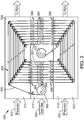
- a system 100involves transporting a flexible web substrate 106 back and forth between first and second precursor zones 110, 112 along a spiral transport path (or "spiral path").
- an isolation zone 116 interposed between precursor zones 110, 112contains an inert fluid (e.g., purge gas) to prevent precursors in precursor zones 110, 112 from mixing, as described in the '421 application.
- the inert fluidmay comprise an inert liquid, but more preferably consists essentially of an inert gas, such as nitrogen (N 2 ) or CO 2 .
- first and second precursor gasesare introduced into the respective first and second precursor zones 110, 112 from first and second precursor delivery systems 120, 122.
- Precursor delivery systems 120, 122may include precursor source containers (not shown) located outside or within precursor zones 110, 112. Additionally or alternatively, precursor delivery systems 120, 122 may include piping, pumps, valves, tanks, and other associated equipment for supplying precursor gases into precursor zones 110, 112.
- An inert gas delivery system 126is similarly included for injecting inert gas into isolation zone 116.
- delivery systems 120, 122, 126are depicted in the schematic view of FIG. 1 as establishing a lateral gas flow, in some embodiments delivery systems 120, 122, 126 may establish a cross-flow across the width of substrate 106, i.e., a flow that is normal to the FIG. 1 page.
- Precursor zones 110, 112 and isolation zone 116are defined and bordered by an outer reaction chamber housing or vessel 130.
- Vessel 130is divided by first and second dividers 134, 136 into three sub-chambers, namely, a first precursor chamber 150, a second precursor chamber 152 and an inert gas chamber 156.
- Vessel 130may comprise a pressure vessel or vacuum vessel substantially isolating the process space from the external environment. In other embodiments, vessel 130 may have entrance and exit passageways for interfacing with other process modules or equipment.
- system 100inhibits the migration of Precursor 1 from first precursor zone 110 into isolation zone 116, and inhibits the migration of Precursor 2 from second precursor zone 112 into isolation zone 116.
- a series of first passageways 160 through first divider 134are spaced apart to receive wound segments 162 of substrate 106, and a corresponding series of second passageways 164 are provided through second divider 136. Passageways 160, 164 are preferably configured to restrict the flow of gases between the zones 110, 112, 116, to avoid or limit diffusion of precursor gases into a common zone.
- passageways 160, 164preferably comprise slits having a width (exaggerated in FIG. 1 ) that is slightly greater than the thickness of substrate 106 and a length (not shown) extending into the plane of FIG. 1 ( i.e ., normal to the page) that is slightly greater than a width of substrate 106.
- Passageways 160, 164may include slits sized only slightly thicker and wider than the thickness and width of substrate 106 passing through them, leaving only a very small amount of headroom and margins to allow substrate 106 to pass therethrough without scraping against the sides of passageways 160, 164.
- headroom and marginsmay range between microns and millimeters in certain embodiments.
- Passageways 160, 164may also include elongate tunnels through which substrate 106 passes. Such slits and tunnels are sometimes referred to as slit valves, although no actual moving valve gate is utilized. Passageways 160,164 are arranged and configured for substrate 106 to be threaded therethrough back and forth between first and second precursor zones 110, 112 multiple times, and each time through isolation zone 116. Isolation zone 116 is, thus, preferably separated (albeit imperfectly) from first precursor zone 110 by first divider 134 and from second precursor zone 112 by second divider 136.
- isolation zone 116essentially consists of a series of long narrow passageways extending completely between precursor zones 110, 112.
- no common inert gas chamber 156connects the passageways, so inert gas is injected directly into the passageways medially of first and second precursor zones 110,112 to help prevent precursor migration and mixing.
- Isolation zone 116 of this embodimentwould include a manifold, or a number of manifolds, for routing inert gas lines to nozzles along the sides of the passageways.
- the manifold or manifoldswould be formed in the material of the reaction chamber bordering the passageways, and may be connected to an inert gas delivery system along the sides of the system, or at an end of the system.
- First roll 166may include a removable spool (not shown) loaded onto a payout spindle (not shown) of system 100.
- Substrate 106is wound along the spiral path defined by a progression of rollers 168 (or other turning guides) for multiple revolutions converging toward a central roll 170 or inner take-up spindle (not shown) proximal of the innermost turning guides 172.
- Central roll 170may also include a removable spool (not shown) loaded onto the inner take-up spindle, in which a mechanical drive turns the payout and/or take-up spindle to wind (or reverses direction to unwind) substrate 106 around central roll 170.
- Rollers 168may be idler rollers or mechanically driven, in which case they may be synchronously driven. Rollers 168 are positioned such that flexible substrate 106 transits back and forth through first and second precursor zones 110, 112 multiple times and each time through isolation zone 116. Accordingly, a first set of rollers 174 are diagonally located along first precursor zone 110, and a second set of rollers 176 are diagonally located in second precursor zone 112 directly opposite and mirroring first set of rollers 174. In some embodiments, first and/or second sets of rollers may be located within an isolation zone, or sets of rollers may be divided between precursor and isolation zones.
- An idler roller 179is positioned in isolation zone 116, proximal to the first roll 166 to tension substrate 106 as it is unwound from first roll 166 and wound around the spiral path onto central roll 170.
- the progression of rollers 168is arranged so that only a first side 180 of substrate 106 contacts rollers 168, and a second side or outer major surface 182 of substrate 106 opposite first side 180 is substantially free from mechanical contact with rollers 168.
- flexible substrate 106is wound at an interior of the spiral transport path to inhibit outer surface 182 from mechanically contacting the substrate transport mechanism ( i.e ., rollers 168) and damaging the thin film formed on outer major surface 182.
- a thin filmmay also be deposited on first side 180 of substrate 106, albeit of inferior quality due to the contact of first side 180 with rollers 168.
- each revolution of substrate 106 around the spiral pathit is sequentially exposed to first precursor zone 110, isolation zone 116, and second precursor zone 112, thereby completing one ALD cycle, and then again to isolation zone 116 in preparation for the next revolution and the next ALD cycle.
- the residence time in each of the precursor zones 110, 112changes on each revolution, as the distance traversed by substrate 106 between successive rollers 168 in the spiral path deceases.
- the number of ALD cyclesis determined by the number of revolutions made by substrate 106 around the spiral path, and the total number of precursor zones traversed along the spiral path, as described with respect to FIG. 2 , below.
- the spiral pathis akin to a spirangle, i.e ., a spiral made out of substantially straight line segments instead of a continuous curve.
- the rectangular spirangle of FIG. 1is formed from a set of straight web segments between successive rollers 168, with the succession of web segments arranged to converge to the central roll 170.
- the spiral pathmay be in the shape of various other polygons other than a square.
- a uniform and high quality film of consistent thicknessmay be grown, despite the fact that the residence time in each of the precursor zones 110, 112 may be significantly different for each cycle, provided that the precursor dosing and purging exposure times for the shortest residence times of the innermost revolution of substrate 106 are sufficient to provide the required dosing and purging.
- the spiral configurationalso lends itself well to the concept of a double pass process, in which the central roll 170 acts as a "temporary" core.
- the first roll 166 of a starting substrateis loaded onto a payout spindle at a location outside of the spiral transport path such as, for example, in a load lock (not shown) or adjacent an atmosphere-vacuum feedthough 408 ( FIG. 4 ).
- the load lock or atmosphere-vacuum feedthough 408may be mounted to the outside of vessel 130 for atmosphere-to-vacuum staging.
- One suitable atmosphere-vacuum feedthoughis manufactured by Energy Conversion Devices, Inc., of Auburn Hills, MI.
- a "leader" of webmay be used, which stays attached to central roll 170 and adapted in system 100 for multiple substrate coating runs.
- Each new roll of starting substrate materialis attached to the leader in the load lock, then wound into the spiral transport path and onto central roll 170, before reversing the transport direction to feed substrate 106 back out of system 100 and onto first roll 166.
- Substrate 106is then wound through the progression of rollers 168, onto central roll 170, and then the transport direction is reversed so that substrate 106 is rewound back onto first roll 166, providing two full passes through the complete system 100. Accordingly, a thin film coating is applied both as substrate 106 is rolled into system 100, as well as back out, thereby achieving the double pass process.
- some embodimentsmay wind substrate 106 without any precursor gas in precursor zones 110, 112, i.e ., with precursor delivery systems 120, 122 deactivated.
- the precursor delivery systems 120, 122are reactivated to inject Precursors 1 and 2 into precursor zones 110, 112, respectively.
- the transport directionis reversed and substrate 106 is transited back out of system 100 and onto first roll 166, thereby completing a single pass process.
- the leadermay be made of or coated with a special material that minimizes coating buildup on the leader.
- the leadermay be made of or coated with a material including fluorine, such as PTFE (TEFLON ® ), which has been shown to prevent ALD film nucleation for many process chemistries.
- PTFETEFLON ®
- Leader materials or leader coating materials containing silicone, or other hydrophobic materials, or materials which inhibit formation of hydroxyl groups or chemisorption of ALD precursorsmay also be used to minimize or prevent coating buildup on the leader.
- FIG. 2illustrates a system 200 according to another embodiment, for coating a substrate 206.
- System 200includes first and second precursor zones 210, 212, and a third precursor zone 214 located therebetween.
- system 200provides a stack arrangement of the three precursor zones 210, 212, 214 separated by isolation zones 216 and 218.
- reactive first, second, and third precursor gases(Precursor 1, Precursor 2, and Precursor 3) are introduced into the respective first, second, and third precursor zones 210, 212, 214 from corresponding first, second, and third precursor delivery systems 220, 222, 224.
- Precursors 1-3may be the same or different precursor gases, capable of producing more than one ALD cycle for each revolution on outermost substrate coils 263.
- system 200includes a first set of rollers 274 that are diagonally located along first precursor zone 210.
- a second set of rollers 276are (optionally) divided into a set of major-portion rollers 277 that are diagonally located in second precursor zone 212 and a set of minor-portion rollers 278 arranged in third precursor zone 214.
- Major-portion rollers 277form an outer major spiral portion 284 spanning from the first to the second precursor zones 210 and 212, and extending through third precursor zone 214, thereby facilitating multiple ALD cycles on each outermost segment 263 per each revolution.
- Minor-portion rollers 278form an inner minor spiral portion 286 such that innermost substrate segments 288 pass through a subset of the precursor zones, e .
- Minor spiral portion 286therefore facilitates exposure to one ALD cycle per each innermost revolution of innermost substrate segments 288.
- minor-portion rollersmay also be arranged within the second precursor zone 212, to produce multiple ALD cycles on each revolution of the substrate.
- a greater number of intermediate precursor zonesmay also be used in some embodiments.
- FIG. 3illustrates a thin film deposition system 300 in accordance with another embodiment for depositing a thin film on a substrate 306 using a plasma based process of the kind described in the '826 and '234 applications, in which oxygen radicals or other radicals are utilized as a co-reactant precursor.
- a plasma based processof the kind described in the '826 and '234 applications, in which oxygen radicals or other radicals are utilized as a co-reactant precursor.
- TMAis introduced in first and second precursor zones 310, 312, and CO 2 is injected into an isolation zone 316 at a flow rate sufficient to achieve a differential pressure slightly higher than precursor zones 310, 312 to prevent migration of TMA precursor into isolation zone 316.
- Plasma 390is generated in isolation zone 316 proximal of substrate 306.
- Plasma 390is generated by a radicals generator 394 at a location spaced a sufficient distance from first and second precursor zones 310, 312 such that the oxygen radicals recombine before they can migrate into precursor zones 310, 312.
- the outer major surface 382is exposed to gaseous radical species during each transit through one or more of the isolation and precursor zones 316, 310, and 312.
- radicalsmay also be deactivated by an active radicals deactivation device 398, such as a vapor species that facilitates the deactivation, or by the use of materials that would react with the radicals to either trap or deactivate them, for example, a getter or a catalyst.
- an active radicals deactivation device 398such as a vapor species that facilitates the deactivation, or by the use of materials that would react with the radicals to either trap or deactivate them, for example, a getter or a catalyst.
- an active radicals deactivation device 398such as a vapor species that facilitates the deactivation, or by the use of materials that would react with the radicals to either trap or deactivate them, for example, a getter or a catalyst.
- each ALD cycledeposits approximately two angstroms ( ⁇ ) of thin film onto substrate 306 so that one revolution of the substrate results in deposition of approximately 4 ⁇ of material on substrate 306.
- a configuration with eight revolutionswould result in deposition of 32 ⁇ of thin film as substrate unwinds from a payout roll onto a central roll, and another 32 ⁇ of thin film as the substrate is reversed and wound back onto the payout roll for a total of approximately 64 ⁇ of thin film, which is a sufficient thickness to provide barrier layer properties for food packaging applications.
- the thin film deposited by the roll-to-roll ALD systems and methods described hereinmay be used in commercial food packaging applications for a polymer web on the order of approximately 1-4 meters wide and approximately 12 microns thick.
- Thin flexible polymer web substrate materials of the kind used for food packaginghaving a thickness of less than about 25 microns ( ⁇ m) and a width greater than approximately 200 mm, or thicker substrates having a thickness of 25 to 200 microns and a width greater than 300 mm, may also be used.
- a thin film deposited by the roll-to-roll ALD method described herein, with roller contact on only one side of the substrate, and having a thickness of approximately 60 ⁇is expected to exhibit WVTR of better (less) than 0.5 g/m 2 /day, when measured at 38 degrees Celsius, at 90% relative humidity.
- the coating on the un-touched sideis expected to have a WVTR of less than 0.5 g/m 2 /day @ 38 °C, 90% Relative Humidity. Under ideal conditions, the WVTR may be under 0.1 g/m 2 /day. While the surface directly contacting the rollers may be coated, it would not be expected to provide a significant barrier contribution, relative to the untouched surface, due to mechanical damage.
- Example 1For the system described in paragraphs [0024] and [0026], above, a coating growth rate of 3-4 ⁇ of Al 2 O 3 per revolution is expected, resulting in approximately 6 nm total thickness using the double-pass described.
- the coating on the un-touched sideis expected to have a WVTR of less than 0.5 g/m 2 /day @ 38 °C, 90% Relative Humidity. Under ideal conditions, the WVTR may be under 0.1 g/m 2 /day. While the surface directly contacting the rollers may be coated, it would not be expected to provide a significant barrier contribution, relative to the untouched surface, due to mechanical damage.
- the coating on the un-touched sideis expected to have a WVTR of less than 0.01 g/m 2 /day @ 38 °C, 90% Relative Humidity. Under ideal conditions, the WVTR may be under 0.001 g/m 2 /day. While the surface directly contacting the rollers may be coated, it would not be expected to provide a significant barrier contribution, relative to the untouched surface, due to mechanical damage.
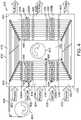
- FIG. 4illustrates a system 400 for depositing a thin film on substrate 406, in accordance with another radical-enhanced ALD embodiment.
- System 400includes the previously discussed atmosphere-vacuum feedthrough 408, as well as first, second, and third precursor zones 410, 412, 414, with a first isolation zone 416 interposed between first and third precursor zones 410 and 414, and a second isolation zone 418 interposed between second and third precursor zones 412 and 414.
- reactive first, second, and third precursor gases(Precursor 1, Precursor 2, and Precursor 3) are introduced into the respective first, second, and third precursor zones 410, 412, 414 from first, second, and third precursor delivery systems 420, 422, 424.
- Inert gasis introduced into first and second isolation zones 416 and 418 from respective inert gas delivery systems 426 and 428. As mentioned previously, gases may be injected or introduced into the various zones in a direction normal to the page, flowing across the width of the flexible substrate.
- Precursor zones 410, 412, 414 and isolation zones 416, 418are defined and bordered by an outer reaction chamber or vessel 430 and a central roll housing or central chamber 432.
- Four dividers 434, 436, 438, 440divide vessel 430 into five chambers.
- First and second precursor chambers 450, 452are each continuations chambers; however, the internal arrangement of dividers 436 and 438, in conjunction with central roll housing 432 splits a third precursor chamber into a pair of sub-chambers or portions, namely, portions 454A and 454B.
- Inert gas chambersare also similarly divided into portions 456A, 456B, and portions 458A, 458B, respectively. "A" and "B" portions may be communicatively coupled via ducting.
- Precursors 1-3may be the same or different precursor gases.
- a metal-forming precursore . g ., TMA
- an oxygen plasma 490is generated by a radicals generator 494 from an inert gas in first and second isolation zones 416, 418, each revolution of substrate 406 about the spiral path results in four ALD cycles, improving the overall processing time.
- additional zonesare possible.
Landscapes
- Chemical & Material Sciences (AREA)
- General Chemical & Material Sciences (AREA)
- Chemical Kinetics & Catalysis (AREA)
- Engineering & Computer Science (AREA)
- Materials Engineering (AREA)
- Mechanical Engineering (AREA)
- Metallurgy (AREA)
- Organic Chemistry (AREA)
- Chemical Vapour Deposition (AREA)
- Physical Vapour Deposition (AREA)
Description
- This application claims the benefit under 35 U.S.C. § 119(e) from
U.S. Provisional Patent Application No. 61/366,927, filed July 23, 2010 - The field of the disclosure relates to thin film deposition, including atomic layer deposition (ALD), on flexible substrates.
U.S. Patent Application 11/691,421, filed March 26, 2007 US 2007/0224348 A1 ("the '421 application"), which is incorporated herein by reference, describes a system and method for ALD in which a flexible substrate is transported back and forth between first and second precursor zones separated by an isolation zone into which an inert gas is injected to inhibit the migration of precursor gases out of the precursor zones.U.S. Patent Application 12/980,234, filed December 28, 2010 2011/0159204 A1 ("the '234 application") which claims priority toU.S. Provisional Patent Application No. 61/290,826, filed December 29, 2009 - In certain embodiments of the '421, '234 and '826 applications, the substrate may be woven along a serpentine path around rollers or other turning guides spaced apart along the first and second precursor zones, as shown in
FIGS. 1 ,2 , and4 of the '421 application. This serpentine path configuration results in both sides of the substrate being contacted by the rollers as the substrate moves through the system. The present inventor has recognized that such mechanical contact can interfere with the ALD process, as it may disturb the chemisorbed precursor or result in mechanical damage to the coating and/or underlying substrate. This damage is generally caused by imperfections or particles on the surface of rollers, or by surface imperfections, such as bumps; spikes, general surface roughness, or particles on the surface of the substrate. When such features contact, the thin brittle oxide film may be broken, compromising its barrier properties. - The '421 application describes various turning guides as alternatives to rollers. One alternative described involves sprockets that utilize perforations along the margins of the web, as in camera film reels. Sprockets or other similar turning guides that contact the web along its edges may eliminate contact to most of the web surface. The present inventor has recognized that sprockets and similar turning guides may be difficult or economically impractical to implement when very thin and wide substrate web material is used, as is common in commercial food packaging applications, wherein polymer web on the order of approximately 1-4 meters wide and about 12 microns thick is common. Thin flexible polymer web substrate materials of the kind used for food packaging, having a thickness of less than approximately 25 microns (µm) and a width greater than approximately 200 mm, or thicker substrates having a thickness of approximately 25 to 200 microns and a width greater than about 300 mm, may sag, kink, crease, stretch or misfeed when not supported along substantially their entire width as they pass around the turning guides.
- In another alternative described in the '421 application, the turning guides may comprise fluid bearings (e.g., gas bearings) that support the substrate on a dynamic cushion of fluid, such as precursor gas and/or inert gas injected through small perforations in a bearing race of the fluid bearing. However, fluid bearings are complicated and difficult to implement in practice.
FIG. 1 is a schematic cross-sectional view illustrating a system and method for ALD on a flexible substrate in which a substrate is moved through a reaction chamber along a spiral transport path, in accordance with a first embodiment.FIG. 2 is a schematic cross-sectional view illustrating a system and method for ALD, in accordance with a second embodiment, including an intermediate precursor zone providing a stack arrangement of three precursor zones for outermost substrate coils.FIG. 3 is a schematic cross-sectional view illustrating a system and method including a plasma based process for ALD on a flexible substrate, in accordance with a third embodiment.FIG. 4 is a schematic cross-sectional view illustrating a system and method for radical-enhanced ALD on a flexible substrate using a five zone stack configuration, in accordance with a fourth embodiment.- With reference to
FIG. 1 , asystem 100 according to the present disclosure involves transporting aflexible web substrate 106 back and forth between first andsecond precursor zones system 100 shown inFIG. 1 , anisolation zone 116 interposed betweenprecursor zones precursor zones second precursor zones precursor delivery systems Precursor delivery systems precursor zones precursor delivery systems precursor zones gas delivery system 126 is similarly included for injecting inert gas intoisolation zone 116. Althoughdelivery systems FIG. 1 as establishing a lateral gas flow, in someembodiments delivery systems substrate 106,i.e., a flow that is normal to theFIG. 1 page. Precursor zones isolation zone 116 are defined and bordered by an outer reaction chamber housing orvessel 130. Vessel 130 is divided by first andsecond dividers first precursor chamber 150, asecond precursor chamber 152 and aninert gas chamber 156.Vessel 130 may comprise a pressure vessel or vacuum vessel substantially isolating the process space from the external environment. In other embodiments,vessel 130 may have entrance and exit passageways for interfacing with other process modules or equipment.- To substantially prevent non-ALD reactions caused by mixing of non-adsorbed quantities of
Precursors 1 and Precursor 2 in one of thechambers system 100 inhibits the migration of Precursor 1 fromfirst precursor zone 110 intoisolation zone 116, and inhibits the migration of Precursor 2 fromsecond precursor zone 112 intoisolation zone 116. A series offirst passageways 160 throughfirst divider 134 are spaced apart to receivewound segments 162 ofsubstrate 106, and a corresponding series ofsecond passageways 164 are provided throughsecond divider 136.Passageways zones passageways FIG. 1 ) that is slightly greater than the thickness ofsubstrate 106 and a length (not shown) extending into the plane ofFIG. 1 (i.e., normal to the page) that is slightly greater than a width ofsubstrate 106.Passageways substrate 106 passing through them, leaving only a very small amount of headroom and margins to allowsubstrate 106 to pass therethrough without scraping against the sides ofpassageways Passageways substrate 106 passes. Such slits and tunnels are sometimes referred to as slit valves, although no actual moving valve gate is utilized. Passageways 160,164 are arranged and configured forsubstrate 106 to be threaded therethrough back and forth between first andsecond precursor zones isolation zone 116.Isolation zone 116 is, thus, preferably separated (albeit imperfectly) fromfirst precursor zone 110 byfirst divider 134 and fromsecond precursor zone 112 bysecond divider 136. - In an alternate embodiment (not shown),
inert gas chamber 156 ofisolation zone 116 anddividers isolation zone 116 essentially consists of a series of long narrow passageways extending completely betweenprecursor zones inert gas chamber 156 connects the passageways, so inert gas is injected directly into the passageways medially of first and second precursor zones 110,112 to help prevent precursor migration and mixing.Isolation zone 116 of this embodiment would include a manifold, or a number of manifolds, for routing inert gas lines to nozzles along the sides of the passageways. The manifold or manifolds would be formed in the material of the reaction chamber bordering the passageways, and may be connected to an inert gas delivery system along the sides of the system, or at an end of the system. - During ALD thin-film processing, the
substrate 106 is unwound from afirst roll 166.First roll 166 may include a removable spool (not shown) loaded onto a payout spindle (not shown) ofsystem 100.Substrate 106 is wound along the spiral path defined by a progression of rollers 168 (or other turning guides) for multiple revolutions converging toward acentral roll 170 or inner take-up spindle (not shown) proximal of theinnermost turning guides 172.Central roll 170 may also include a removable spool (not shown) loaded onto the inner take-up spindle, in which a mechanical drive turns the payout and/or take-up spindle to wind (or reverses direction to unwind)substrate 106 aroundcentral roll 170.Rollers 168 may be idler rollers or mechanically driven, in which case they may be synchronously driven.Rollers 168 are positioned such thatflexible substrate 106 transits back and forth through first andsecond precursor zones isolation zone 116. Accordingly, a first set ofrollers 174 are diagonally located alongfirst precursor zone 110, and a second set ofrollers 176 are diagonally located insecond precursor zone 112 directly opposite and mirroring first set ofrollers 174. In some embodiments, first and/or second sets of rollers may be located within an isolation zone, or sets of rollers may be divided between precursor and isolation zones. Anidler roller 179 is positioned inisolation zone 116, proximal to thefirst roll 166 totension substrate 106 as it is unwound fromfirst roll 166 and wound around the spiral path ontocentral roll 170. The progression ofrollers 168 is arranged so that only afirst side 180 ofsubstrate 106contacts rollers 168, and a second side or outermajor surface 182 ofsubstrate 106 oppositefirst side 180 is substantially free from mechanical contact withrollers 168. In other words,flexible substrate 106 is wound at an interior of the spiral transport path to inhibitouter surface 182 from mechanically contacting the substrate transport mechanism (i.e., rollers 168) and damaging the thin film formed on outermajor surface 182. A thin film may also be deposited onfirst side 180 ofsubstrate 106, albeit of inferior quality due to the contact offirst side 180 withrollers 168. - During each revolution of
substrate 106 around the spiral path, it is sequentially exposed tofirst precursor zone 110,isolation zone 116, andsecond precursor zone 112, thereby completing one ALD cycle, and then again toisolation zone 116 in preparation for the next revolution and the next ALD cycle. In the arrangement shown inFIG. 1 , the residence time in each of theprecursor zones substrate 106 betweensuccessive rollers 168 in the spiral path deceases. The number of ALD cycles is determined by the number of revolutions made bysubstrate 106 around the spiral path, and the total number of precursor zones traversed along the spiral path, as described with respect toFIG. 2 , below. - When the
system 100 and thewound substrate 106 are viewed along the rotational axes ofrollers 168, as schematically shown inFIG. 1 , the spiral path is akin to a spirangle,i.e., a spiral made out of substantially straight line segments instead of a continuous curve. The rectangular spirangle ofFIG. 1 is formed from a set of straight web segments betweensuccessive rollers 168, with the succession of web segments arranged to converge to thecentral roll 170. In other embodiments, the spiral path may be in the shape of various other polygons other than a square. In any case, because of ALD's saturation characteristics, a uniform and high quality film of consistent thickness may be grown, despite the fact that the residence time in each of theprecursor zones substrate 106 are sufficient to provide the required dosing and purging. - The spiral configuration also lends itself well to the concept of a double pass process, in which the
central roll 170 acts as a "temporary" core. In such a process, thefirst roll 166 of a starting substrate is loaded onto a payout spindle at a location outside of the spiral transport path such as, for example, in a load lock (not shown) or adjacent an atmosphere-vacuum feedthough 408 (FIG. 4 ). As an alternative to venting reaction chamber orvessel 130, the load lock or atmosphere-vacuum feedthough 408 may be mounted to the outside ofvessel 130 for atmosphere-to-vacuum staging. One suitable atmosphere-vacuum feedthough is manufactured by Energy Conversion Devices, Inc., of Auburn Hills, MI. A "leader" of web may be used, which stays attached tocentral roll 170 and adapted insystem 100 for multiple substrate coating runs. Each new roll of starting substrate material is attached to the leader in the load lock, then wound into the spiral transport path and ontocentral roll 170, before reversing the transport direction to feedsubstrate 106 back out ofsystem 100 and ontofirst roll 166.Substrate 106 is then wound through the progression ofrollers 168, ontocentral roll 170, and then the transport direction is reversed so thatsubstrate 106 is rewound back ontofirst roll 166, providing two full passes through thecomplete system 100. Accordingly, a thin film coating is applied both assubstrate 106 is rolled intosystem 100, as well as back out, thereby achieving the double pass process. By utilizing the leader web, loading a new substrate roll is simplified and all of the leading end of new substrate material is fully coated with the same number of ALD cycles, reducing waste. Of course, the trailing end of substrate offirst roll 166 would not get fully coated, as the trailing end remains connected to a reel of thefirst roll 166 and would not complete the full number of revolutions throughsystem 100 around the spiral path. - In order to degas, scrub, or remove water vapor proximal to
substrate 106 as it enters and transits around the spiral path fromfirst roll 166 tocentral roll 170, some embodiments may windsubstrate 106 without any precursor gas inprecursor zones precursor delivery systems substrate 106 ontocentral roll 170, theprecursor delivery systems Precursors precursor zones Precursors precursor zones substrate 106 is transited back out ofsystem 100 and ontofirst roll 166, thereby completing a single pass process. - The leader may be made of or coated with a special material that minimizes coating buildup on the leader. In particular, the leader may be made of or coated with a material including fluorine, such as PTFE (TEFLON®), which has been shown to prevent ALD film nucleation for many process chemistries. Leader materials or leader coating materials containing silicone, or other hydrophobic materials, or materials which inhibit formation of hydroxyl groups or chemisorption of ALD precursors may also be used to minimize or prevent coating buildup on the leader.
FIG. 2 illustrates asystem 200 according to another embodiment, for coating asubstrate 206.System 200 includes first andsecond precursor zones third precursor zone 214 located therebetween. Thus,system 200 provides a stack arrangement of the threeprecursor zones isolation zones Precursor 1,Precursor 2, and Precursor 3) are introduced into the respective first, second, andthird precursor zones precursor delivery systems system 100 ofFIG. 1 ,system 200 includes a first set ofrollers 274 that are diagonally located alongfirst precursor zone 210. A second set ofrollers 276 are (optionally) divided into a set of major-portion rollers 277 that are diagonally located insecond precursor zone 212 and a set of minor-portion rollers 278 arranged inthird precursor zone 214. Major-portion rollers 277 form an outermajor spiral portion 284 spanning from the first to thesecond precursor zones third precursor zone 214, thereby facilitating multiple ALD cycles on eachoutermost segment 263 per each revolution. Minor-portion rollers 278 form an innerminor spiral portion 286 such thatinnermost substrate segments 288 pass through a subset of the precursor zones,e.g., first andthird precursor zones 210 and 214 (but not second precursor zone 212). Minorspiral portion 286 therefore facilitates exposure to one ALD cycle per each innermost revolution ofinnermost substrate segments 288. In some embodiments (not shown) minor-portion rollers may also be arranged within thesecond precursor zone 212, to produce multiple ALD cycles on each revolution of the substrate. In addition, a greater number of intermediate precursor zones may also be used in some embodiments.FIG. 3 illustrates a thinfilm deposition system 300 in accordance with another embodiment for depositing a thin film on asubstrate 306 using a plasma based process of the kind described in the '826 and '234 applications, in which oxygen radicals or other radicals are utilized as a co-reactant precursor. In one radical-enhanced ALD configuration, TMA is introduced in first andsecond precursor zones isolation zone 316 at a flow rate sufficient to achieve a differential pressure slightly higher thanprecursor zones isolation zone 316. To generate oxygen radicals that react with TMA molecules chemisorbed at an outermajor surface 382 ofsubstrate 306, aplasma 390 is generated inisolation zone 316 proximal ofsubstrate 306.Plasma 390 is generated by aradicals generator 394 at a location spaced a sufficient distance from first andsecond precursor zones precursor zones radicals generator 394, the outermajor surface 382 is exposed to gaseous radical species during each transit through one or more of the isolation andprecursor zones radicals deactivation device 398, such as a vapor species that facilitates the deactivation, or by the use of materials that would react with the radicals to either trap or deactivate them, for example, a getter or a catalyst. In a system in which TMA is introduced into first andsecond precursor zones isolation zone 316, each revolution results in two ALD cycles. In the case of TMA and oxygen radicals (O•) generated from CO2 plasma, a thin film of Al2O3 is deposited. In other embodiments, the radicals may be introduced in any one of the precursor zones.- When a plasma-enhanced technique is used (for example, using oxygen radicals as a co-reactant in
isolation zone 316 with TMA precursor in bothprecursor zones 310, 312) each ALD cycle deposits approximately two angstroms (Å) of thin film ontosubstrate 306 so that one revolution of the substrate results in deposition of approximately 4Å of material onsubstrate 306. A configuration with eight revolutions (not shown) would result in deposition of 32Å of thin film as substrate unwinds from a payout roll onto a central roll, and another 32Å of thin film as the substrate is reversed and wound back onto the payout roll for a total of approximately 64Å of thin film, which is a sufficient thickness to provide barrier layer properties for food packaging applications. - The thin film deposited by the roll-to-roll ALD systems and methods described herein may be used in commercial food packaging applications for a polymer web on the order of approximately 1-4 meters wide and approximately 12 microns thick. Thin flexible polymer web substrate materials of the kind used for food packaging, having a thickness of less than about 25 microns (µm) and a width greater than approximately 200 mm, or thicker substrates having a thickness of 25 to 200 microns and a width greater than 300 mm, may also be used.
- A thin film deposited by the roll-to-roll ALD method described herein, with roller contact on only one side of the substrate, and having a thickness of approximately 60Å is expected to exhibit WVTR of better (less) than 0.5 g/m2/day, when measured at 38 degrees Celsius, at 90% relative humidity.
- Deposition of AL2O3 on PET substrate material:
- 1. Substrate width: approx. 3 meters.
- 2. Substrate thickness: 12 to 25 microns.
- 3. Substrate temperature: room temperature (~20 °C) to 120 °C.
- 4. First precursor zone: TMA at 0.002 to 0.050 Torr partial pressure TMA.
- 5. Second precursor zone: Oxygen-containing plasma generated from CO2 or a mixture of N2 and O2, with a total nominal pressure of 1.2 Torr.
- 6. Precursor exposure: the substrate travels between 5cm and 500 cm within each of the plasma and the TMA-containing precursor zones on each revolution.
- 7. Web speed: 0.5 to 10 m/s.
- 8. Thin film growth rate expected: 1.5 to 2.0 Å per ALD process cycle (per revolution).
- 9. Number of revolutions: 10 per pass (10 each for payout and rewind).
- 10. Total coating film thickness expected: 3-4 nm (total for double pass).
- The coating on the un-touched side is expected to have a WVTR of less than 0.5 g/m2/day @ 38 °C, 90% Relative Humidity. Under ideal conditions, the WVTR may be under 0.1 g/m2/day. While the surface directly contacting the rollers may be coated, it would not be expected to provide a significant barrier contribution, relative to the untouched surface, due to mechanical damage.
- Alternate configuration of Example 1: For the system described in paragraphs [0024] and [0026], above, a coating growth rate of 3-4 Å of Al2O3 per revolution is expected, resulting in approximately 6 nm total thickness using the double-pass described. The coating on the un-touched side is expected to have a WVTR of less than 0.5 g/m2/day @ 38 °C, 90% Relative Humidity. Under ideal conditions, the WVTR may be under 0.1 g/m2/day. While the surface directly contacting the rollers may be coated, it would not be expected to provide a significant barrier contribution, relative to the untouched surface, due to mechanical damage.
- Deposition of AL2O3 high barrier film on PEN substrate material:
- 1. Substrate width: approx. 2 meters.
- 2. Substrate thickness: 50-150 microns.
- 3. Substrate temperature: room temperature (~20 °C) to 200 °C.
- 4. First precursor zone: TMA at 0.002 to 0.050 Torr partial pressure TMA.
- 5. Second precursor zone: TMA at 0.002 to 0.050 Torr partial pressure TMA.
- 6. Isolation zone: Oxygen-containing plasma generated from CO2 or a mixture of N2 and O2, with a total nominal pressure of 1.2 Torr.
- 6. Precursor exposure: the substrate travels between 5cm and 500 cm within each of the plasma and the TMA-containing precursor zones on each revolution.
- 7. Web speed: 0.1 to 5 m/s.
- 8. Thin film growth rate expected: 1.5 to 2.0 Å per ALD process cycle (3-4 Å per revolution).
- 9. Number of revolutions: 25 per pass (25 each for payout and rewind).
- 10. Total coating film thickness expected: approx 18 nm (total for double pass).
- The coating on the un-touched side is expected to have a WVTR of less than 0.01 g/m2/day @ 38 °C, 90% Relative Humidity. Under ideal conditions, the WVTR may be under 0.001 g/m2/day. While the surface directly contacting the rollers may be coated, it would not be expected to provide a significant barrier contribution, relative to the untouched surface, due to mechanical damage.
FIG. 4 illustrates asystem 400 for depositing a thin film onsubstrate 406, in accordance with another radical-enhanced ALD embodiment.System 400 includes the previously discussed atmosphere-vacuum feedthrough 408, as well as first, second, andthird precursor zones first isolation zone 416 interposed between first andthird precursor zones second isolation zone 418 interposed between second andthird precursor zones system 400 in use, reactive first, second, and third precursor gases (Precursor 1,Precursor 2, and Precursor 3) are introduced into the respective first, second, andthird precursor zones precursor delivery systems second isolation zones gas delivery systems Precursor zones isolation zones vessel 430 and a central roll housing orcentral chamber 432. Fourdividers divide vessel 430 into five chambers. First andsecond precursor chambers dividers 436 and 438, in conjunction withcentral roll housing 432 splits a third precursor chamber into a pair of sub-chambers or portions, namely,portions 454A and 454B. Inert gas chambers are also similarly divided intoportions portions 458A, 458B, respectively. "A" and "B" portions may be communicatively coupled via ducting.- Precursors 1-3 may be the same or different precursor gases. When a metal-forming precursor (e.g., TMA) is introduced into first, second, and
third precursor zones oxygen plasma 490 is generated by aradicals generator 494 from an inert gas in first andsecond isolation zones substrate 406 about the spiral path results in four ALD cycles, improving the overall processing time. As with previously mentioned embodiments, additional zones are possible. - It will be obvious to those having skill in the art that many changes may be made to the details of the above-described embodiments without departing from the underlying principles of the invention. The scope of the present invention should, therefore, be determined only by the following claims.
Claims (15)
- A system for depositing a thin film on a flexible substrate, comprising:a first precursor zone into which a first precursor gas is introduced when the system is in use;a second precursor zone into which a second precursor gas is introduced when the system is in use;an isolation zone interposed between the first and second precursor zones and into which an inert gas is introduced when the system is in use; anda substrate transport mechanism for reciprocally transporting the flexible substrate along a spiral transport path back and forth between the first and second precursor zones multiple times and each time through the isolation zone, including:to thereby inhibit an outer surface of the flexible substrate from mechanically contacting the substrate transport mechanism and damaging the thin film formed on the outer surface of the flexible substrate.a plurality of first turning guides spaced apart along the first precursor zone,a plurality of second turning guides spaced apart along the second precursor zone, the first and second turning guides arranged for guiding the flexible substrate into a spiral configuration, anda take-up spindle proximal to innermost turning guides and positioned for winding the flexible substrate at an interior of the spiral transport path,
- The system of claim 1, further comprising a radicals generator in proximity to the spiral transport path for generating a gaseous radical species within at least one of the first precursor zone, the second precursor zone, and the isolation zone, to thereby facilitate exposure of the flexible substrate to the gaseous radical species.
- The system of claim 1, further comprising a third precursor zone into which a third precursor gas is introduced when the system is in use, the third precursor zone being interposed between the first and second precursor zones, and in which the isolation zone comprises a first isolation zone interposed between the first and third precursor zones and a second isolation zone interposed between the second and third precursor zones, and in which at least a portion of the spiral transport path extends into the third precursor zone.
- The system of claim 3, further comprising a radicals generator within each of the first and second isolation zones.
- The system of either of claims 2 or 4, wherein the radicals generator includes a plasma generator; AND/OR further comprising an active radicals deactivation device.
- The system of any of the preceding claims, further comprising a leader having a first end portion coupled to the take-up spindle, an opposing end portion configured to connect to the flexible substrate at a periphery of the spiral transport path, and a middle portion wound around the turning guides along the spiral transport path.
- The system of claim 6, in which the leader is made of or coated with a material that inhibits ALD film nucleation upon the leader or formation of hydroxyl groups or chemisorption of ALD precursors on the leader; AND/OR in which the leader is made of or coated with a material selected from the group consisting of: materials containing fluorine, materials containing silicone, hydrophobic materials, and combinations thereof.
- The system of any of the preceding claims, in which the flexible substrate has a width greater than 200 mm and a thickness less than approximately 25 microns; AND/OR in which the flexible substrate has a width of approximately 1 meter to approximately 4 meters.
- The system of any of the preceding claims, in which each of the first and second turning guides includes a roller; AND/OR in which the substrate transport mechanism further comprises a payout spindle for paying out the flexible substrate from a roll located at the periphery of the spiral transport path.
- A method for depositing a thin film on a flexible substrate, comprising:introducing a first precursor gas into a first precursor zone;introducing a second precursor gas into a second precursor zone spaced apart from the first precursor zone;introducing an inert gas into an isolation zone between the first and second precursor zones; andguiding a flexible substrate along a spiral transport path defined by a progression of turning guides that converge toward an inner take-up spindle about which the substrate is wound, the spiral transport path causing the flexible substrate to transit back and forth through the first and second precursor zones multiple times and each time through the isolation zone, while a portion of the first precursor gas adsorbs to an outer major surface of the flexible substrate during its transit through the first precursor zone, and during a subsequent transit through the second precursor zone the second precursor gas reacts with the adsorbed first precursor at the outer major surface of the flexible substrate, to thereby deposit a thin film on the outer major surface that is free from mechanical contact with the turning guides.
- The method of claim 10, further comprising introducing a third precursor gas into a third precursor zone interposed between the first and second precursor zones, and in which the isolation zone comprises a first isolation zone interposed between the first and third precursor zones and a second isolation zone interposed between the second and third precursor zones.
- The method of claim 11, wherein guiding the flexible substrate includes guiding the flexible substrate along an outer major portion of the spiral transit path spanning between the first and second precursor zones and extending through the first and second isolation zones, then along an inner minor portion of the spiral transit path within the outer major portion, the inner minor portion spanning between the first and third precursor zones and extending through the first isolation zone.
- The method of any one of claims 10 to 12, further comprising exposing the outer major surface to a gaseous radical species during each transit through one or more of the isolation and precursor zones.
- The method of claim 13, wherein the gaseous radical species comprises oxygen-containing radicals and optionally further comprising deactivating the gaseous radical species with an active radicals deactivation device.
- The method of any one of claims 10 to 14, whereby the thin film formed on the outer major surface comprises a barrier layer having a water vapor transmission rate of less than 5.0 x 10⁻¹ g/m2/day; AND/OR in which the flexible substrate has a width greater than 200 mm and a thickness less than approximately 25 microns; AND/OR further comprising unwinding the flexible substrate from a payout spindle located at the periphery of the spiral transport path; AND/OR further comprising reversing the direction of transport of the flexible substrate to achieve a double pass process; AND/OR further comprising connecting the flexible substrate to a leader having a first end portion coupled to the inner take-up spindle, an opposing end portion configured to connect to the flexible substrate at the periphery of the spiral transport path, and a middle portion threaded through the turning guides along the spiral transport path.
Applications Claiming Priority (2)
| Application Number | Priority Date | Filing Date | Title |
|---|---|---|---|
| US36692710P | 2010-07-23 | 2010-07-23 | |
| PCT/US2011/045049WO2012012744A2 (en) | 2010-07-23 | 2011-07-22 | Substrate transport mechanism contacting a single side of a flexible web substrate for roll-to-roll thin film deposition |
Publications (3)
| Publication Number | Publication Date |
|---|---|
| EP2596146A2 EP2596146A2 (en) | 2013-05-29 |
| EP2596146A4 EP2596146A4 (en) | 2016-06-22 |
| EP2596146B1true EP2596146B1 (en) | 2017-02-22 |
Family
ID=45493837
Family Applications (1)
| Application Number | Title | Priority Date | Filing Date |
|---|---|---|---|
| EP11810477.7ANot-in-forceEP2596146B1 (en) | 2010-07-23 | 2011-07-22 | Substrate transport mechanism contacting a single side of a flexible web substrate for roll-to-roll thin film deposition |
Country Status (8)
| Country | Link |
|---|---|
| US (1) | US9297076B2 (en) |
| EP (1) | EP2596146B1 (en) |
| JP (1) | JP5828895B2 (en) |
| KR (1) | KR101791033B1 (en) |
| CN (1) | CN103119198B (en) |
| BR (1) | BR112013000116A2 (en) |
| ES (1) | ES2617956T3 (en) |
| WO (1) | WO2012012744A2 (en) |
Families Citing this family (14)
| Publication number | Priority date | Publication date | Assignee | Title |
|---|---|---|---|---|
| TWI501873B (en) | 2011-12-27 | 2015-10-01 | Nitto Denko Corp | Transparent gas barrier film, transparent gas barrier film manufacturing method, organic EL element, solar cell and thin film battery |
| CN104379808A (en)* | 2012-06-15 | 2015-02-25 | 皮考逊公司 | Coating a substrate web by atomic layer deposition |
| WO2014084698A1 (en)* | 2012-11-30 | 2014-06-05 | 주식회사 엘지화학 | Film formation apparatus |
| CN103966572A (en)* | 2013-02-05 | 2014-08-06 | 王东君 | Roll-to-roll atomic layer deposition apparatus and application method thereof |
| JP2014154361A (en)* | 2013-02-08 | 2014-08-25 | Nitto Denko Corp | Manufacturing method for transparent gas barrier film, manufacturing apparatus for transparent gas barrier film, and organic electro-luminescence device |
| US9435028B2 (en)* | 2013-05-06 | 2016-09-06 | Lotus Applied Technology, Llc | Plasma generation for thin film deposition on flexible substrates |
| EP3022331A4 (en) | 2013-07-16 | 2017-01-04 | 3M Innovative Properties Company | Roll processing of film |
| US9556514B2 (en) | 2014-02-06 | 2017-01-31 | Veeco Ald Inc. | Spatial deposition of material using short-distance reciprocating motions |
| US9133546B1 (en)* | 2014-03-05 | 2015-09-15 | Lotus Applied Technology, Llc | Electrically- and chemically-active adlayers for plasma electrodes |
| CN104152844A (en)* | 2014-08-11 | 2014-11-19 | 江南石墨烯研究院 | Method for carrying substrate in vacuum |
| WO2016061468A2 (en)* | 2014-10-17 | 2016-04-21 | Lotus Applied Technology, Llc | High-speed deposition of mixed oxide barrier films |
| KR101834171B1 (en)* | 2016-08-29 | 2018-03-05 | 에스에프씨주식회사 | Apparatus for evaluation of deposition process in manufacturing of organic thin film |
| DE102019007935B4 (en)* | 2019-11-14 | 2023-06-29 | Elfolion Gmbh | Process for processing flexible substrates and vacuum processing system for implementing the process |
| CN115702258B (en)* | 2020-06-10 | 2025-05-16 | 3M创新有限公司 | Roll-to-roll vapor deposition apparatus and method |
Family Cites Families (39)
| Publication number | Priority date | Publication date | Assignee | Title |
|---|---|---|---|---|
| US1350662A (en)* | 1918-05-29 | 1920-08-24 | Firestone Tire & Rubber Co | Rack |
| SE393967B (en) | 1974-11-29 | 1977-05-31 | Sateko Oy | PROCEDURE AND PERFORMANCE OF LAYING BETWEEN THE STORAGE IN A LABOR PACKAGE |
| JPS6030124A (en) | 1983-07-28 | 1985-02-15 | Fuji Electric Corp Res & Dev Ltd | Multistage electrode type semiconductor thin-film forming device |
| JPH0734332B2 (en)* | 1986-03-12 | 1995-04-12 | 株式会社ト−ビ | Method for producing transparent conductive film |
| JP2824808B2 (en) | 1990-11-16 | 1998-11-18 | キヤノン株式会社 | Apparatus for continuously forming large-area functional deposited films by microwave plasma CVD |
| KR940000259A (en) | 1992-06-12 | 1994-01-03 | 게리 리 그리스월드 | System and Method for Making Multi-Layer Films on Tape Supports |
| JP3911780B2 (en) | 1997-08-12 | 2007-05-09 | 株式会社カツシカ | Stick-shaped cosmetic feed container |
| US6186090B1 (en)* | 1999-03-04 | 2001-02-13 | Energy Conversion Devices, Inc. | Apparatus for the simultaneous deposition by physical vapor deposition and chemical vapor deposition and method therefor |
| US6660326B2 (en) | 2000-08-04 | 2003-12-09 | Tomoegawa Paper Co. Ltd. | Production method for monolayer powder film and production apparatus therefor |
| KR100492769B1 (en) | 2001-05-17 | 2005-06-07 | 주식회사 엘지이아이 | An apparatus for continuous plasma polymerizing with a vertical chamber |
| US7081271B2 (en) | 2001-12-07 | 2006-07-25 | Applied Materials, Inc. | Cyclical deposition of refractory metal silicon nitride |
| US7250083B2 (en) | 2002-03-08 | 2007-07-31 | Sundew Technologies, Llc | ALD method and apparatus |
| EP1347077B1 (en) | 2002-03-15 | 2006-05-17 | VHF Technologies SA | Apparatus and method for the production of flexible semiconductor devices |
| US7067439B2 (en) | 2002-06-14 | 2006-06-27 | Applied Materials, Inc. | ALD metal oxide deposition process using direct oxidation |
| EP1556902A4 (en)* | 2002-09-30 | 2009-07-29 | Miasole | APPARATUS AND METHOD FOR MANUFACTURING CON CURRENT FOR LARGE SCALE PRODUCTION OF THIN FILM SOLAR CELLS |
| US6821563B2 (en) | 2002-10-02 | 2004-11-23 | Applied Materials, Inc. | Gas distribution system for cyclical layer deposition |
| RU2332523C2 (en) | 2002-12-26 | 2008-08-27 | Топпан Принтинг Ко., Лтд. | Vacuum deposition device and method of film production by vacuum deposition |
| US6878207B2 (en) | 2003-02-19 | 2005-04-12 | Energy Conversion Devices, Inc. | Gas gate for isolating regions of differing gaseous pressure |
| US7018713B2 (en) | 2003-04-02 | 2006-03-28 | 3M Innovative Properties Company | Flexible high-temperature ultrabarrier |
| US6888172B2 (en) | 2003-04-11 | 2005-05-03 | Eastman Kodak Company | Apparatus and method for encapsulating an OLED formed on a flexible substrate |
| US20050005846A1 (en)* | 2003-06-23 | 2005-01-13 | Venkat Selvamanickam | High throughput continuous pulsed laser deposition process and apparatus |
| JP4349043B2 (en)* | 2003-08-29 | 2009-10-21 | コニカミノルタオプト株式会社 | Plasma discharge treatment apparatus and plasma discharge treatment method |
| JP2005126756A (en)* | 2003-10-23 | 2005-05-19 | Matsushita Electric Ind Co Ltd | Method and apparatus for producing compound semiconductor thin film |
| US20050172897A1 (en) | 2004-02-09 | 2005-08-11 | Frank Jansen | Barrier layer process and arrangement |
| JP4601975B2 (en) | 2004-03-01 | 2010-12-22 | 東京エレクトロン株式会社 | Deposition method |
| KR100618606B1 (en) | 2004-06-02 | 2006-09-08 | 한국전기연구원 | How to manufacture a metal oxide device |
| US20060073276A1 (en) | 2004-10-04 | 2006-04-06 | Eric Antonissen | Multi-zone atomic layer deposition apparatus and method |
| GB0423685D0 (en) | 2004-10-26 | 2004-11-24 | Dow Corning Ireland Ltd | Improved method for coating a substrate |
| JPWO2006093168A1 (en)* | 2005-03-04 | 2008-08-07 | 株式会社ユーテック | CVD apparatus, multilayer film forming method using the same, and multilayer film formed thereby |
| US20070224248A1 (en)* | 2006-03-21 | 2007-09-27 | Smith Steven A | Method and compositions for treating acne |
| CN101406108B (en)* | 2006-03-26 | 2011-06-22 | 罗特斯应用技术公司 | Atomic layer deposition system and method for coating flexible substrates |
| US7456429B2 (en) | 2006-03-29 | 2008-11-25 | Eastman Kodak Company | Apparatus for atomic layer deposition |
| US20070281089A1 (en)* | 2006-06-05 | 2007-12-06 | General Electric Company | Systems and methods for roll-to-roll atomic layer deposition on continuously fed objects |
| US8187679B2 (en)* | 2006-07-29 | 2012-05-29 | Lotus Applied Technology, Llc | Radical-enhanced atomic layer deposition system and method |
| US7976899B2 (en) | 2006-10-23 | 2011-07-12 | General Electric Company | Methods for selective deposition of graded materials on continuously fed objects |
| DE102007009615A1 (en)* | 2007-02-26 | 2008-08-28 | Leybold Optics Gmbh | Vacuum coating apparatus for front surface of strip material has two process chambers containing process roller, connected by transfer chamber containing strip feed and strip winding rollers, rear surface of strip contacting all rollers |
| CN101631661B (en)* | 2007-06-25 | 2012-03-14 | 夏普株式会社 | Firing device |
| JP2010070837A (en)* | 2008-09-22 | 2010-04-02 | Fujifilm Corp | Film roll and cleaning method for film deposition system |
| CN102239278A (en)* | 2008-12-05 | 2011-11-09 | 莲花应用技术有限责任公司 | High rate deposition of thin films with improved barrier layer properties |
- 2011
- 2011-07-22EPEP11810477.7Apatent/EP2596146B1/ennot_activeNot-in-force
- 2011-07-22ESES11810477.7Tpatent/ES2617956T3/enactiveActive
- 2011-07-22BRBR112013000116Apatent/BR112013000116A2/ennot_activeIP Right Cessation
- 2011-07-22WOPCT/US2011/045049patent/WO2012012744A2/enactiveApplication Filing
- 2011-07-22CNCN201180035854.8Apatent/CN103119198B/ennot_activeExpired - Fee Related
- 2011-07-22USUS13/189,018patent/US9297076B2/enactiveActive
- 2011-07-22JPJP2013520887Apatent/JP5828895B2/ennot_activeExpired - Fee Related
- 2011-07-22KRKR1020137001703Apatent/KR101791033B1/ennot_activeExpired - Fee Related
Non-Patent Citations (1)
| Title |
|---|
| None* |
Also Published As
| Publication number | Publication date |
|---|---|
| WO2012012744A2 (en) | 2012-01-26 |
| EP2596146A4 (en) | 2016-06-22 |
| JP5828895B2 (en) | 2015-12-09 |
| EP2596146A2 (en) | 2013-05-29 |
| KR20130043163A (en) | 2013-04-29 |
| BR112013000116A2 (en) | 2016-05-24 |
| US20120021128A1 (en) | 2012-01-26 |
| CN103119198A (en) | 2013-05-22 |
| WO2012012744A3 (en) | 2012-04-12 |
| US9297076B2 (en) | 2016-03-29 |
| CN103119198B (en) | 2015-08-19 |
| ES2617956T3 (en) | 2017-06-20 |
| JP2013535575A (en) | 2013-09-12 |
| KR101791033B1 (en) | 2017-10-27 |
Similar Documents
| Publication | Publication Date | Title |
|---|---|---|
| EP2596146B1 (en) | Substrate transport mechanism contacting a single side of a flexible web substrate for roll-to-roll thin film deposition | |
| US9238868B2 (en) | Atomic layer deposition method for coating flexible substrates | |
| KR101714538B1 (en) | Inhibiting excess precursor transport between separate precursor zones in an atomic layer deposition system | |
| EP2692899B1 (en) | Roll to roll atomic layer deposition (ald) | |
| EP2519657B1 (en) | Oxygen radical generation for radical-enhanced thin film deposition | |
| JP6119745B2 (en) | Winding film forming system | |
| EP3284591B1 (en) | LAMINATE AND METHOD FOR PRODUCING SAME |
Legal Events
| Date | Code | Title | Description |
|---|---|---|---|
| PUAI | Public reference made under article 153(3) epc to a published international application that has entered the european phase | Free format text:ORIGINAL CODE: 0009012 | |
| 17P | Request for examination filed | Effective date:20130109 | |
| AK | Designated contracting states | Kind code of ref document:A2 Designated state(s):AL AT BE BG CH CY CZ DE DK EE ES FI FR GB GR HR HU IE IS IT LI LT LU LV MC MK MT NL NO PL PT RO RS SE SI SK SM TR | |
| DAX | Request for extension of the european patent (deleted) | ||
| A4 | Supplementary search report drawn up and despatched | Effective date:20160524 | |
| RIC1 | Information provided on ipc code assigned before grant | Ipc:C23C 16/448 20060101AFI20160518BHEP Ipc:C23C 16/44 20060101ALI20160518BHEP | |
| GRAP | Despatch of communication of intention to grant a patent | Free format text:ORIGINAL CODE: EPIDOSNIGR1 | |
| INTG | Intention to grant announced | Effective date:20161004 | |
| GRAS | Grant fee paid | Free format text:ORIGINAL CODE: EPIDOSNIGR3 | |
| GRAA | (expected) grant | Free format text:ORIGINAL CODE: 0009210 | |
| AK | Designated contracting states | Kind code of ref document:B1 Designated state(s):AL AT BE BG CH CY CZ DE DK EE ES FI FR GB GR HR HU IE IS IT LI LT LU LV MC MK MT NL NO PL PT RO RS SE SI SK SM TR | |
| REG | Reference to a national code | Ref country code:GB Ref legal event code:FG4D | |
| REG | Reference to a national code | Ref country code:CH Ref legal event code:EP | |
| REG | Reference to a national code | Ref country code:AT Ref legal event code:REF Ref document number:869350 Country of ref document:AT Kind code of ref document:T Effective date:20170315 | |
| REG | Reference to a national code | Ref country code:IE Ref legal event code:FG4D | |
| REG | Reference to a national code | Ref country code:DE Ref legal event code:R096 Ref document number:602011035270 Country of ref document:DE | |
| REG | Reference to a national code | Ref country code:ES Ref legal event code:FG2A Ref document number:2617956 Country of ref document:ES Kind code of ref document:T3 Effective date:20170620 | |
| REG | Reference to a national code | Ref country code:FR Ref legal event code:PLFP Year of fee payment:7 | |
| REG | Reference to a national code | Ref country code:LT Ref legal event code:MG4D | |
| REG | Reference to a national code | Ref country code:NL Ref legal event code:MP Effective date:20170222 | |
| REG | Reference to a national code | Ref country code:AT Ref legal event code:MK05 Ref document number:869350 Country of ref document:AT Kind code of ref document:T Effective date:20170222 | |
| PG25 | Lapsed in a contracting state [announced via postgrant information from national office to epo] | Ref country code:GR Free format text:LAPSE BECAUSE OF FAILURE TO SUBMIT A TRANSLATION OF THE DESCRIPTION OR TO PAY THE FEE WITHIN THE PRESCRIBED TIME-LIMIT Effective date:20170523 Ref country code:NO Free format text:LAPSE BECAUSE OF FAILURE TO SUBMIT A TRANSLATION OF THE DESCRIPTION OR TO PAY THE FEE WITHIN THE PRESCRIBED TIME-LIMIT Effective date:20170522 Ref country code:LT Free format text:LAPSE BECAUSE OF FAILURE TO SUBMIT A TRANSLATION OF THE DESCRIPTION OR TO PAY THE FEE WITHIN THE PRESCRIBED TIME-LIMIT Effective date:20170222 Ref country code:FI Free format text:LAPSE BECAUSE OF FAILURE TO SUBMIT A TRANSLATION OF THE DESCRIPTION OR TO PAY THE FEE WITHIN THE PRESCRIBED TIME-LIMIT Effective date:20170222 Ref country code:HR Free format text:LAPSE BECAUSE OF FAILURE TO SUBMIT A TRANSLATION OF THE DESCRIPTION OR TO PAY THE FEE WITHIN THE PRESCRIBED TIME-LIMIT Effective date:20170222 | |
| PG25 | Lapsed in a contracting state [announced via postgrant information from national office to epo] | Ref country code:AT Free format text:LAPSE BECAUSE OF FAILURE TO SUBMIT A TRANSLATION OF THE DESCRIPTION OR TO PAY THE FEE WITHIN THE PRESCRIBED TIME-LIMIT Effective date:20170222 Ref country code:RS Free format text:LAPSE BECAUSE OF FAILURE TO SUBMIT A TRANSLATION OF THE DESCRIPTION OR TO PAY THE FEE WITHIN THE PRESCRIBED TIME-LIMIT Effective date:20170222 Ref country code:NL Free format text:LAPSE BECAUSE OF FAILURE TO SUBMIT A TRANSLATION OF THE DESCRIPTION OR TO PAY THE FEE WITHIN THE PRESCRIBED TIME-LIMIT Effective date:20170222 Ref country code:PT Free format text:LAPSE BECAUSE OF FAILURE TO SUBMIT A TRANSLATION OF THE DESCRIPTION OR TO PAY THE FEE WITHIN THE PRESCRIBED TIME-LIMIT Effective date:20170622 Ref country code:LV Free format text:LAPSE BECAUSE OF FAILURE TO SUBMIT A TRANSLATION OF THE DESCRIPTION OR TO PAY THE FEE WITHIN THE PRESCRIBED TIME-LIMIT Effective date:20170222 Ref country code:SE Free format text:LAPSE BECAUSE OF FAILURE TO SUBMIT A TRANSLATION OF THE DESCRIPTION OR TO PAY THE FEE WITHIN THE PRESCRIBED TIME-LIMIT Effective date:20170222 Ref country code:BG Free format text:LAPSE BECAUSE OF FAILURE TO SUBMIT A TRANSLATION OF THE DESCRIPTION OR TO PAY THE FEE WITHIN THE PRESCRIBED TIME-LIMIT Effective date:20170522 | |
| PG25 | Lapsed in a contracting state [announced via postgrant information from national office to epo] | Ref country code:EE Free format text:LAPSE BECAUSE OF FAILURE TO SUBMIT A TRANSLATION OF THE DESCRIPTION OR TO PAY THE FEE WITHIN THE PRESCRIBED TIME-LIMIT Effective date:20170222 Ref country code:CZ Free format text:LAPSE BECAUSE OF FAILURE TO SUBMIT A TRANSLATION OF THE DESCRIPTION OR TO PAY THE FEE WITHIN THE PRESCRIBED TIME-LIMIT Effective date:20170222 Ref country code:RO Free format text:LAPSE BECAUSE OF FAILURE TO SUBMIT A TRANSLATION OF THE DESCRIPTION OR TO PAY THE FEE WITHIN THE PRESCRIBED TIME-LIMIT Effective date:20170222 Ref country code:SK Free format text:LAPSE BECAUSE OF FAILURE TO SUBMIT A TRANSLATION OF THE DESCRIPTION OR TO PAY THE FEE WITHIN THE PRESCRIBED TIME-LIMIT Effective date:20170222 | |
| REG | Reference to a national code | Ref country code:DE Ref legal event code:R097 Ref document number:602011035270 Country of ref document:DE | |
| PG25 | Lapsed in a contracting state [announced via postgrant information from national office to epo] | Ref country code:PL Free format text:LAPSE BECAUSE OF FAILURE TO SUBMIT A TRANSLATION OF THE DESCRIPTION OR TO PAY THE FEE WITHIN THE PRESCRIBED TIME-LIMIT Effective date:20170222 Ref country code:DK Free format text:LAPSE BECAUSE OF FAILURE TO SUBMIT A TRANSLATION OF THE DESCRIPTION OR TO PAY THE FEE WITHIN THE PRESCRIBED TIME-LIMIT Effective date:20170222 Ref country code:SM Free format text:LAPSE BECAUSE OF FAILURE TO SUBMIT A TRANSLATION OF THE DESCRIPTION OR TO PAY THE FEE WITHIN THE PRESCRIBED TIME-LIMIT Effective date:20170222 | |
| PLBE | No opposition filed within time limit | Free format text:ORIGINAL CODE: 0009261 | |
| STAA | Information on the status of an ep patent application or granted ep patent | Free format text:STATUS: NO OPPOSITION FILED WITHIN TIME LIMIT | |
| 26N | No opposition filed | Effective date:20171123 | |
| PG25 | Lapsed in a contracting state [announced via postgrant information from national office to epo] | Ref country code:SI Free format text:LAPSE BECAUSE OF FAILURE TO SUBMIT A TRANSLATION OF THE DESCRIPTION OR TO PAY THE FEE WITHIN THE PRESCRIBED TIME-LIMIT Effective date:20170222 | |
| REG | Reference to a national code | Ref country code:CH Ref legal event code:PL | |
| REG | Reference to a national code | Ref country code:IE Ref legal event code:MM4A | |
| PG25 | Lapsed in a contracting state [announced via postgrant information from national office to epo] | Ref country code:LI Free format text:LAPSE BECAUSE OF NON-PAYMENT OF DUE FEES Effective date:20170731 Ref country code:CH Free format text:LAPSE BECAUSE OF NON-PAYMENT OF DUE FEES Effective date:20170731 Ref country code:IE Free format text:LAPSE BECAUSE OF NON-PAYMENT OF DUE FEES Effective date:20170722 | |
| REG | Reference to a national code | Ref country code:BE Ref legal event code:MM Effective date:20170731 | |
| REG | Reference to a national code | Ref country code:FR Ref legal event code:PLFP Year of fee payment:8 | |
| PG25 | Lapsed in a contracting state [announced via postgrant information from national office to epo] | Ref country code:LU Free format text:LAPSE BECAUSE OF NON-PAYMENT OF DUE FEES Effective date:20170722 | |
| PG25 | Lapsed in a contracting state [announced via postgrant information from national office to epo] | Ref country code:BE Free format text:LAPSE BECAUSE OF NON-PAYMENT OF DUE FEES Effective date:20170731 | |
| PG25 | Lapsed in a contracting state [announced via postgrant information from national office to epo] | Ref country code:MT Free format text:LAPSE BECAUSE OF NON-PAYMENT OF DUE FEES Effective date:20170722 | |
| REG | Reference to a national code | Ref country code:DE Ref legal event code:R082 Ref document number:602011035270 Country of ref document:DE Representative=s name:WEIDNER STERN JESCHKE PATENTANWAELTE PARTNERSC, DE | |
| PG25 | Lapsed in a contracting state [announced via postgrant information from national office to epo] | Ref country code:MC Free format text:LAPSE BECAUSE OF FAILURE TO SUBMIT A TRANSLATION OF THE DESCRIPTION OR TO PAY THE FEE WITHIN THE PRESCRIBED TIME-LIMIT Effective date:20170222 Ref country code:HU Free format text:LAPSE BECAUSE OF FAILURE TO SUBMIT A TRANSLATION OF THE DESCRIPTION OR TO PAY THE FEE WITHIN THE PRESCRIBED TIME-LIMIT; INVALID AB INITIO Effective date:20110722 | |
| PG25 | Lapsed in a contracting state [announced via postgrant information from national office to epo] | Ref country code:CY Free format text:LAPSE BECAUSE OF NON-PAYMENT OF DUE FEES Effective date:20170222 | |
| PG25 | Lapsed in a contracting state [announced via postgrant information from national office to epo] | Ref country code:MK Free format text:LAPSE BECAUSE OF FAILURE TO SUBMIT A TRANSLATION OF THE DESCRIPTION OR TO PAY THE FEE WITHIN THE PRESCRIBED TIME-LIMIT Effective date:20170222 | |
| PG25 | Lapsed in a contracting state [announced via postgrant information from national office to epo] | Ref country code:TR Free format text:LAPSE BECAUSE OF FAILURE TO SUBMIT A TRANSLATION OF THE DESCRIPTION OR TO PAY THE FEE WITHIN THE PRESCRIBED TIME-LIMIT Effective date:20170222 | |
| PG25 | Lapsed in a contracting state [announced via postgrant information from national office to epo] | Ref country code:AL Free format text:LAPSE BECAUSE OF FAILURE TO SUBMIT A TRANSLATION OF THE DESCRIPTION OR TO PAY THE FEE WITHIN THE PRESCRIBED TIME-LIMIT Effective date:20170222 Ref country code:IS Free format text:LAPSE BECAUSE OF FAILURE TO SUBMIT A TRANSLATION OF THE DESCRIPTION OR TO PAY THE FEE WITHIN THE PRESCRIBED TIME-LIMIT Effective date:20170622 | |
| PGFP | Annual fee paid to national office [announced via postgrant information from national office to epo] | Ref country code:FR Payment date:20220616 Year of fee payment:12 | |
| PGFP | Annual fee paid to national office [announced via postgrant information from national office to epo] | Ref country code:IT Payment date:20220729 Year of fee payment:12 Ref country code:ES Payment date:20220809 Year of fee payment:12 | |
| PGFP | Annual fee paid to national office [announced via postgrant information from national office to epo] | Ref country code:GB Payment date:20230831 Year of fee payment:13 | |
| PGFP | Annual fee paid to national office [announced via postgrant information from national office to epo] | Ref country code:DE Payment date:20230614 Year of fee payment:13 | |
| PG25 | Lapsed in a contracting state [announced via postgrant information from national office to epo] | Ref country code:FR Free format text:LAPSE BECAUSE OF NON-PAYMENT OF DUE FEES Effective date:20230731 | |
| PG25 | Lapsed in a contracting state [announced via postgrant information from national office to epo] | Ref country code:IT Free format text:LAPSE BECAUSE OF NON-PAYMENT OF DUE FEES Effective date:20230722 | |
| REG | Reference to a national code | Ref country code:ES Ref legal event code:FD2A Effective date:20240830 | |
| PG25 | Lapsed in a contracting state [announced via postgrant information from national office to epo] | Ref country code:ES Free format text:LAPSE BECAUSE OF NON-PAYMENT OF DUE FEES Effective date:20230723 | |
| PG25 | Lapsed in a contracting state [announced via postgrant information from national office to epo] | Ref country code:ES Free format text:LAPSE BECAUSE OF NON-PAYMENT OF DUE FEES Effective date:20230723 | |
| REG | Reference to a national code | Ref country code:DE Ref legal event code:R119 Ref document number:602011035270 Country of ref document:DE | |
| GBPC | Gb: european patent ceased through non-payment of renewal fee | Effective date:20240722 | |
| PG25 | Lapsed in a contracting state [announced via postgrant information from national office to epo] | Ref country code:DE Free format text:LAPSE BECAUSE OF NON-PAYMENT OF DUE FEES Effective date:20250201 | |
| PG25 | Lapsed in a contracting state [announced via postgrant information from national office to epo] | Ref country code:GB Free format text:LAPSE BECAUSE OF NON-PAYMENT OF DUE FEES Effective date:20240722 |