EP2593932B1 - Methods and systems for coordinating vehicular traffic using in-vehicle virtual traffic control signals enabled by vehicle-to-vehicle communications - Google Patents
Methods and systems for coordinating vehicular traffic using in-vehicle virtual traffic control signals enabled by vehicle-to-vehicle communicationsDownload PDFInfo
- Publication number
- EP2593932B1 EP2593932B1EP11735753.3AEP11735753AEP2593932B1EP 2593932 B1EP2593932 B1EP 2593932B1EP 11735753 AEP11735753 AEP 11735753AEP 2593932 B1EP2593932 B1EP 2593932B1
- Authority
- EP
- European Patent Office
- Prior art keywords
- vehicle
- traffic control
- dynamic traffic
- travel
- vehicles
- Prior art date
- Legal status (The legal status is an assumption and is not a legal conclusion. Google has not performed a legal analysis and makes no representation as to the accuracy of the status listed.)
- Active
Links
Images


Classifications
- G—PHYSICS
- G08—SIGNALLING
- G08G—TRAFFIC CONTROL SYSTEMS
- G08G1/00—Traffic control systems for road vehicles
- G—PHYSICS
- G08—SIGNALLING
- G08G—TRAFFIC CONTROL SYSTEMS
- G08G1/00—Traffic control systems for road vehicles
- G08G1/16—Anti-collision systems
- G08G1/161—Decentralised systems, e.g. inter-vehicle communication
- G08G1/163—Decentralised systems, e.g. inter-vehicle communication involving continuous checking
- G—PHYSICS
- G08—SIGNALLING
- G08G—TRAFFIC CONTROL SYSTEMS
- G08G1/00—Traffic control systems for road vehicles
- G08G1/16—Anti-collision systems
- G08G1/164—Centralised systems, e.g. external to vehicles
Definitions
- the present inventiongenerally relates to the field of vehicular traffic control.
- the present inventionis directed to methods and systems for coordinating vehicular traffic using in-vehicle virtual traffic control signals enabled by vehicle-to-vehicle communications.
- traffic lightsalso known as stoplights, traffic lamps, traffic signals, and other related terms
- traffic lights and intersection-based signsare the predominant means of controlling traffic flow
- other methods of intersection-based traffic managementhave been the subject of some experimentation.
- US Patent Application US2002/198660discloses a method of automatic vehicular traffic flow control proximate to a control area, based on inter-vehicular communication, and comprising using a vehicle passing in the area as a temporary controller.
- the present disclosureis directed to a method of coordinating vehicular traffic proximate to a potential travel-priority conflict zone according to claim 1.
- the present disclosureis directed to a machine-readable storage medium according to claim 12.
- the present disclosureis directed to a system for coordinating vehicular traffic proximate to a potential travel-priority conflict zone according to claim 13.
- V2V communicationsenable development of a dynamic traffic control plan ("DTCP") that can resolve a travel-priority conflict in the potential-conflict zone which, if left unresolved, could result in a collision.
- DTCPdynamic traffic control plan
- a DTCPincludes a set of travel instructions that are communicated to vehicles participating in the ad-hoc network for the particular potential-conflict zone.
- these instructionscan include a sequence by which vehicles approaching from different directions may proceed through a potential-conflict zone, the speed at which vehicles approaching a conflict zone should be traveling, and so forth.
- One important aspect of a DTCPis that the instructions are tailored for the specific vehicles participating in conflict, and are also coordinated with the other vehicles participating in the conflict so as to resolve the conflict without incident. Additionally, this coordination can assist with optimizing vehicle flow through a potential-travel-priority conflict zone as a function of traffic volume, road conditions, as well as other characteristics of travel routes and participating vehicles.
- the systems and methods described hereindo not require intersection-based or road-based infrastructure to resolve such priority conflicts. Instead, the systems and methods of the present disclosure rely on adaptive and ad-hoc vehicle-based systems and methods. However, in yet other embodiments, for example embodiments designed and configured to resolve vehicle-pedestrian priority conflicts, the methods and systems of the present disclosure may benefit from intersection-based infrastructure.
- FIG. 1illustrates an exemplary method 100 of resolving a potential vehicular travel-priority conflict by communicating with approaching vehicles so as to collect data relevant to an incipient conflict, creating a DTCP to avoid or resolve the conflict, and communicating the DTCP to the vehicles participating in the potential conflict.
- Method 100can begin by, for example, at step 105 in which at least two vehicles can approach a potential vehicular travel-priority conflict zone.
- the types of vehicles contemplated in this example, and indeed in the entirety of the present disclosure,can be any propelled, or mobile, vehicle including, for example, a self-propelled, but human-controlled, vehicle having a motor or an engine such as a motorcycle, an automobile, an aircraft, a SEGWAY® personal transporter, an electric cart, a motorized wheelchair, and other similar devices.
- the vehiclecan be any self-propelled and self-controlled vehicle, such as an industrial robot, automated equipment, and other types of automated vehicles.
- the vehiclecan include a human powered vehicle such as a bicycle, a tricycle, a skate-board, and other similar vehicles.
- method 100is equally applicable to a potential vehicular travel-priority conflict involving two vehicles of different types.
- the teachings of the present disclosuremay even be applied to a pedestrian, which for convenience, is included in the term "vehicle.”
- vehiclewhich for convenience, is included in the term "vehicle.”
- a "potential-travel-priority-conflict zone”is a zone where two or more movable objects, for example, vehicles, people, etc., and any combination thereof, have the potential of being in conflict with one another in terms of travel priority. Such a conflict typically, but not necessarily, results in a collision or near-collision between movable objects involved.
- the word "potential"connotes that while an actual conflict can happen, they do not necessarily happen. In other words, while a particular zone has the potential for conflicts, actual conflicts may not happen for a variety of reasons, such as very low traffic volumes and attentive vehicle operators, among others.
- the potential-travel-priority-conflict zoneare road intersections, such as a traditional road intersection, controlled-access roadway entrance- and exit-ramps, and merging traffic lanes.
- the potential-conflict zoneneed not be at a fixed location known prior to the occurrence of a travel-priority conflict, as is presumed with the placement of a traditional traffic light.
- the potential-conflict zonecan be at any point on a travel route.
- travel routescan include, but are not limited to, a one-way street, a two-lane road with anti-parallel lanes, or even a parking lot.
- a potential-conflict zonecan occur between a pedestrian and an automobile at an intersection, or at any point not at an intersection.
- the potential-conflict zonecan occur between aircraft in the air, on a taxi-way, or in some other area.
- the conflict zonecan occur in areas not publicly accessible but still accessible by vehicular traffic, such as pedestrian zones, and warehouses that include both mobile industrial equipment and pedestrian traffic.
- the vehiclescommunicate with each other in order to establish a DTCP that utilizes an ad-hoc communication network usable to resolve travel-priority conflicts.
- the vehiclescommunicate with each other using dedicated short-range communications ("DSRC") that can use IEEE 802.11(p) communication protocol. While an example of apparatus used to facilitate DSRC is described in detail below in the context of FIG. 2 , it is sufficient for the time being to understand that DSRC employs a DSRC-capable radio to receive and transmit relevant information.
- DSRCdedicated short-range communications
- DSRC radioscan be included in virtually any type of device, whether included in a vehicle as manufactured, added to a vehicle or vehicle-based dynamic traffic control ("DTC") system using an after-market addition, or included in a mobile communication device (e.g., a cell phone or a smart phone) that is used in conjunction with a vehicle or vehicle-based DTC system.
- DTCdynamic traffic control
- mobile communication devicee.g., a cell phone or a smart phone
- the DSRC protocolis not the only means by which vehicles can communicate.
- Other examples of methods by which vehicles can communicateinclude other radio-frequency communication protocols, cellular communications (including First Generation, Second Generation (2G), Third Generation (3G), Fourth Generation (4G), etc.), Wi-Fi, Wi-Fi enabled internet, laser or other light-based communication or data transfer, and others, as well as combinations thereof.
- a variety of inputscan be used to identify anticipated priority conflicts and establish the DTCP that is subsequently communicated to the other vehicles approaching the travel-priority conflict zone.
- one type of inputincludes vehicle-specific metrics.
- the metricsinclude, but are not limited to, velocity of travel, distance from the conflict zone, vehicle weight, indicia of traffic congestion, and direction of travel.
- Other types of inputscan include travel-route features stored in a travel-route database. Examples of these types of inputs can include, but are not limited to, lane-width, road-width, changes in lane- or road-direction or elevation, obstructions to vehicle travel or visibility, construction projects affecting vehicle flow, and many other similar characteristics that can be appreciated by those skilled in the art.
- inputs that can be used to identify anticipated priority conflictsinclude indirectly acquired factors that can be based on calculations using the above mentioned direct inputs.
- One example illustrating this conceptis the calculation of the stopping distance of a vehicle based on the direct inputs of vehicle velocity, weight, and travel-route surface conditions e.g., surface type (gravel, concrete, asphalt, etc), and surface quality (e.g., dry, wet, snow-covered, ice-covered, etc.).
- surface typegravel, concrete, asphalt, etc
- surface qualitye.g., dry, wet, snow-covered, ice-covered, etc.
- indirectly acquired factorscan also include parametric factors that are based on directly acquired inputs and indirectly acquired factors, which are then analyzed using statistical and mathematical methods well known to those skilled in the art. For example, continuing with the immediately preceding example of stopping distance, a processor in communication with a system can determine whether a vehicle can stop safely before entering a conflict zone based on direct inputs of vehicle velocity and weight that are then used in connection with a statistical analysis algorithm that determines the probability of the vehicle stopping safely. Using this type of parametric analysis can further enhance the sophistication, precision, and accuracy of this aspect of the system. Furthermore, priority conflicts can be anticipated using a process known as beaconing in connection with a location database. The application of these two elements will be discussed in more detail in the context of FIG. 2 .
- vehicles approaching a potential travel-priority-conflict zonecommunicate with each other, using the methods and systems described above, to elect a vehicle that can provide a coordinated set of DTCP instructions to vehicles participating in the ad-hoc vehicle-based network established to avoid any real conflicts that could occur in the potential travel-priority conflict.
- This elected vehiclefor the purposes of the present disclosure, is known as a traffic coordinator.
- the traffic coordinatorcan be elected from among candidates in the ad-hoc vehicle-based network based on any one or more of a number of different factors, including those factors that indicate the ability to stop safely before a conflict zone, the traffic density on the various approaches to the travel-priority conflict zone, and others. For example, a subset of candidates for coordinators may be identified as those leading their respective queue of vehicles on a given approach to a priority-conflict zone (illustrated by FIG. 6 , which is described below in detail). In this example, these vehicles will be the first to arrive at the conflict zone, and are therefore more likely to be in communicative contact with vehicles approaching the conflict zone from other directions. This arrangement facilitates, but is not required for, V2V communication.
- those vehicles leading their respective queuescan prevent the vehicles trailing them from proceeding further, thereby controlling the vehicular traffic flow if so required by the DTCP.
- Other factors that can be used to elect the coordinatorinclude, for example, the ability to stop safely before entering the potential travel-priority-conflict zone, the presence of possible barriers to V2V communication, possible priority status of vehicles approaching the potential conflict zone (e.g., emergency-service vehicles), traffic planning policies favoring higher traffic flow in a given direction, and road features (e.g., blind spots, road curvature, local road topography, vehicle density generally and on specific approaches to the conflict zone, etc).
- road featurese.g., blind spots, road curvature, local road topography, vehicle density generally and on specific approaches to the conflict zone, etc.
- the traffic coordinatorcan broadcast its election as the traffic coordinator, thereby informing proximate vehicles of its identity and location. Also, once elected, the coordinator can establish a DTCP, as described above, and communicate it to the other vehicles approaching the potential-travel-priority-conflict zone. Optionally, the coordinator can periodically re-broadcast its identity as traffic coordinator and re-broadcast the DTCP to confirm control of the potential-conflict zone and inform any newly arrived vehicles.
- While the examples of the present disclosureare primarily directed to localized travel-priority-conflict zones, various teachings found herein can also be applied to ad-hoc vehicle-based networks over a larger geographic area in order to facilitate travel efficiencies on a larger scale.
- traffic coordinators at remote potential-conflict zonescan communicate.
- This communicationcan facilitate regional traffic-flow efficiency by, for example, providing DTCP instructions to clear travel zones of vehicles in preparation for an approaching emergency-service vehicle or, in another example, to coordinate the traffic flow through multiple conflict zones to increase the "green-light split" (i.e., the percentage of time vehicles on a given approach are permitted to proceed through the zone) along a desired travel-route, thereby reacting to variations in traffic density.
- DTCP instructionsto clear travel zones of vehicles in preparation for an approaching emergency-service vehicle or, in another example, to coordinate the traffic flow through multiple conflict zones to increase the "green-light split" (i.e., the percentage of time vehicles on a given approach are permitted to proceed through the zone) along a desired travel-route, thereby reacting to variations in traffic density.
- the ad-hoc systemcan be informed of local traffic planning policies through a program (described in the context of FIG. 2 ) that can affect traffic flow, thereby taking advantage of larger-scale traffic management.
- the traffic coordinatorhaving been elected and the DTCP having been created and communicated to vehicles approaching a potential-travel-priority-conflict zone in the above-described steps, the vehicles can then participate in the DTCP.
- DTCP instructionsare communicated to the vehicles participating in the ad-hoc vehicle-based network corresponding to the potential-travel-priority-conflict zone by providing each vehicle with a virtual traffic control, such as an in-vehicle traffic light.
- the term "virtual" when used in the context of a traffic control, traffic control signal, or other traffic control meansrefers to any such means that is effectively a replacement for one or more traditional infrastructure-based traffic control means, such as traffic lights, traffic signals, traffic signs, etc. as well as a human or automated traffic director that would traditionally be located at a potential travel-priority-conflict zone.
- a red, amber, or green lightis presented to the operator of a vehicle participating in the conflict.
- other types of virtual traffic controlcan be used to communicate the DTCP instructions to vehicles participating in an ad-hoc vehicle-based network for a particular potential-travel-priority-conflict zone.
- the instructionscan be provided aurally to the vehicle operator through a vehicle radio, a global-positioning system (GPS) device, a portable communications device (e.g., a mobile phone), or other similarly enabled system.
- GPSglobal-positioning system
- portable communications devicee.g., a mobile phone
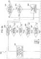
- system 200illustrates a DTC system used to implement, for example, method 100 described in the context of FIG. 1 .
- System 200includes, for example, a (V2V) communications system 204, a processor 208, DTC software 212, a physical memory 216, a user interface 220, and an optional vehicle interface 224.
- V2VV2V
- DTC software 212DTC software 212
- a physical memory 216e.g., a Wi-Fi
- user interface 220e.g., a Wi-Fi Protected Access 220
- vehicle interface 224e.g., a vehicle interface 224.
- These elementscan be used together, in whole or in part, to create a DTCP, communicate a DTCP to other vehicles, receive a DTCP from another vehicle, and execute the instructions supplied by the DTCP, depending on the configuration of DTC system 200 and the needs of the particular DTCP ad-hoc vehicle-based network under consideration.
- DTC system 200
- V2V communications system 204is designed and configured to receive signals from at least one other vehicle within the ad-hoc vehicle-based network at issue that have the same or similar V2V communications system. As described above in the context of FIG. 1 , these signals can include information characterizing the type of vehicle, its weight, its speed, relevant traffic and road conditions, and the manner of approach of a vehicle, among many others. V2V communications system 204 is also designed and configured to provide a communications link between vehicles approaching a potential travel-priority conflict zone, as described above in the context of FIG. 1 , in order to elect a traffic coordinator, collect data, and perform analyses so as to create a DTCP, as well as to communicate the DTCP to the participating vehicles.
- V2V communications system 204is designed and configured to transmit and receive signals communicating DTCP instructions using any one or more of a variety of protocols.
- V2V communications system 204may broadcast signals transmitting DTCP instructions periodically from a vehicle through a process known in the art as "beaconing."
- beaconingthe information described above is communicated at regular intervals and throughout a given geographic area surrounding the vehicle performing the beaconing.
- These beaconing signalscan be received and/or retransmitted by another DTC system similar to system 200 through V2V system 204.
- beaconing signalscan be used in cooperation with on-board location database 228. The use of this location database 228 with the periodically repeated beaconing signals can permit DTC system 200 to track the location of proximate vehicles.
- DTC system 200can anticipate travel-priority conflict zones because the system is informed of, at the minimum, the location and velocity of proximate vehicle in the context of known travel-routes. In some examples, this can permit DTC system 200 to adapt to local vehicle densities and to anticipate, and accommodate, density trends.
- V2V communications system 204may also or, alternatively, be designed and configured to transmit and receive signals using non-beaconing protocols as well, such as signals transmitted to or from another proximate vehicle directly, for example using a handshake, push, or pull protocol, among others.
- non-beaconing protocolssuch as signals transmitted to or from another proximate vehicle directly, for example using a handshake, push, or pull protocol, among others.
- the above-described signalscan be communicated between vehicles using a method known in the art as "Geocasting.” In this method, vehicles can communicate with other vehicles regionally proximate but out of DSRC range by using intervening vehicles as transponders that propagate the DSRC signal.
- Processor 208is designed and configured to receive one or more signal(s) from V2V system 204 and initiate an analysis of the information contained in the signal(s) as a precursor to developing a DTCP.
- Processor 208which can include multiple processors operating together, is linked by connections that enable operative communication between V2V communications system 204, physical memory 216, user interface 220, and vehicle interface 224.
- These communication meanscan include physical connections, such as metal conductors, Ethernet cable, optical fiber, and others well known in the art.
- non-physical connectionssuch as wireless communication over radio frequencies (e.g., BLUETOOTH® radio, WiFi, etc.), mobile communication device frequencies, or optically using visible or non-visible light.
- processor 208need not be specifically dedicated to DTC system 200. Indeed, devices that can be used to supply processor 208 are ubiquitous throughout modern society. These devices include pre-existing processors in vehicles (often referred to as electronic control units, engine control units, or "ECUs"), mobile phones, and many other devices that can be programmed to be used in conjunction with a vehicle or by an operator of a vehicle.
- ECUselectronice control units, engine control units, or "ECUs”
- mobile phonesand many other devices that can be programmed to be used in conjunction with a vehicle or by an operator of a vehicle.
- Processor 208employs DTC software 212 to analyze inputs relevant to anticipated particular potential-travel-priority-conflict zone, as described above in connection to FIG. 1 .
- DTC software 212stored in physical memory 216 and in operative communication with processor 208, can execute any of a wide variety of analytical operations upon inputs in furtherance of developing a DTCP. Examples of these analytical operations have been described previously in the context of FIG. 1 and need no further explanation for those skilled in the art to understand them.
- DTC software 212can include on-board location database 228 and/or travel-route database 232 and/or lane-level data, either or both of which can include information relevant to the creation of a DTCP by DTC system 200, and which can be updated periodically.
- DTC system 200can be used to contribute to the analysis of the anticipated travel-priority conflict depending on the specific application of DTC system 200.
- Exemplary applications of DTC system 200include creating DTCPs to avoid pedestrian-pedestrian conflicts, and pedestrian-motorized vehicle conflicts, in zones that can have unrestricted access (e.g., a public road intersection) or in zones that have restricted access (e.g., pedestrian zone, bike path, parking lot, etc.).
- these databasescan include a building floor plan, a manufacturing-facility or warehouse layout, a map of a city that also includes pedestrian walkways and bike paths (defining vehicle-free zones), and air-routes specified by altitude and geospatial coordinates.
- a building floor plana manufacturing-facility or warehouse layout
- a map of a citythat also includes pedestrian walkways and bike paths (defining vehicle-free zones)
- air-routesspecified by altitude and geospatial coordinates.
- physical memory 216stores DTC software 212 and any necessary desired database, such as on-board location database 228, and travel-route database 232, and/or other information, and is in operative communication with processor 208.
- physical memory 216can include, for example, flash memory, magnetic memory, optical memory, and other types known in the art, and any combination thereof, excluding transitory signals.
- flash memorymagnetic memory
- optical memoryand other types known in the art, and any combination thereof, excluding transitory signals.
- User interface 220is in operative communication with processor 208 and can be designed and configured, for example, to communicate traffic control instructions to an operator of a vehicle needed to comply with a DTCP, thereby obviating an anticipated travel-priority conflict.
- user interface 220is a display capable of displaying red, amber, and green lights in response to an appropriate DTC signal, thereby providing traffic control instructions to the operator of a vehicle that are analogous to instructions provided by a conventional infrastructure-based traffic light, and therefore familiar to vehicle operators.
- instructionscan also be provided by user interface 220 of a mobile communications device, a GPS unit, and can be symbolic (e.g., the in-vehicle traffic light), spoken (e.g., through the speaker unit of a mobile communications device , GPS unit, or in-vehicle sound system), graphically displayed (e.g., a dedicated in-vehicle display, a generic in-vehicle display, a heads-up display or projection, or a mobile communications device), or otherwise communicated.
- a dedicated in-vehicle displaye.g., a generic in-vehicle display, a heads-up display or projection, or a mobile communications device
- User interface 220can also be used by DTC system 200 to solicit input from an operator (or occupant) of the vehicle, such as preferences and settings for the system or to provide additional information in order to inform processor 208 of information relevant to the DTCP.
- the types of relevant informationare described elsewhere in this disclosure, and are also apparent to those skilled in the art.
- DTC system 200can also be used to implement other methods, in addition to method 100, consistent with the teaching of the present disclosure.
- DTC system 200can function equally well in the transmission of signals to other vehicles, as described in the context of FIG. 1 .
- DTC system 200upon receiving data from other vehicles used to create a DTCP, DTC system 200 can transmit the DTCP to the other vehicles using the system.
- DTC system 200may optionally include a vehicle interface 224 that can interact directly with the operative functionality of the vehicle, thereby automatically implementing the DTCP without the cooperation of the vehicle operator.
- vehicle interface 224may, through operative connections to the various vehicle systems (e.g., propulsion, steering, braking, directional signal, etc.) direct the vehicle to conform to the DTCP.
- vehicle interface 224can interact with propulsion and braking systems of the vehicle in order to conform to the instructions.
- This operative connectioncan be enabled through autonomous driving technology as illustrated, for example, in U.S. Patent Application Publication No.
- Vehicle interface 224can also provide vehicle data and information in order to better inform system 200 in the creation of the DTCP.
- vehicle interface 224can provide velocity, heading, vehicle type, acceleration (using an in-vehicle accelerometer), vehicle priority status, and other information relevant to the creation of the DTCP to processor 208. This information can then be used by processor 208 in cooperation with DTC software 212 to create a DTCP.
- this informationmay also be communicated via V2V communications system 204 to another vehicle that has been elected as a traffic coordinator and charged with creating the DTCP.
- FIG. 3illustrates an exemplary instantiation, in which a DTC system 300 is located on-board a vehicle 304, such as an automobile, truck, bus, train, aircraft, etc.
- vehicle 304such as an automobile, truck, bus, train, aircraft, etc.
- DTC system 300can be integrated into vehicle 304 in any of a variety of ways, such as being installed as an after-market device or as an original equipment system.
- DTC system 300contains some or all of the components of DTC system 200 of FIG. 2 , those components can be contained largely or entirely within a single installed device or may alternatively be spread out throughout vehicle 304.
- a mobile device 308can be placed on-board vehicle 304, for example, by the operator (not shown) of the vehicle.
- mobile devicesthat can be used for mobile device 308 include a smart phone, GPS unit, a personal multimedia device, a personal gaming device, and a tablet personal computer, among many other similar devices known to those skilled in the art. Details and examples pertinent to DTC system 300, mobile device 308, and vehicle 304, as well as the means, methods, and mechanisms by which they communicate and interact, are above or are well known in the art, and need not be explained further for those skilled in the art to be able to execute the features and aspects disclosed in FIG. 3 .
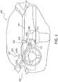
- FIG. 4shows a dashboard region 400 of an automobile 404 containing a DTC system (not shown) of the present disclosure.
- DTC systemsthat can be implemented in automobile 404 include, but are not limited to, DTC systems 200 and 300 of FIGS. 2 and 3 , respectively, each of which can be configured to execute method 100 of FIG. 1 or similar DCT method.
- FIG. 4is provided to particularly illustrate various ways of instantiating a particular type of virtual traffic control, specifically a virtual traffic signal that mimics a traditional infrastructure-type three-light traffic signal configured to implement conventional green, amber, and red phases of the control cycles.
- a three-light virtual traffic signal 408is displayed on a display 412 built into the dashboard 416 of automobile 404.
- Display 412can be, for example, an existing touchscreen-type display for displaying, and/or allowing users to interact with, other features of automobile, such as a sound system, climate-control system, backup-camera system and/or GPS, among others.
- virtual traffic signal 408has three light positions 408A to 408C, for correspondingly displaying a red light, an amber light, and a green light in accordance with the U.S. standard arrangement of colors/phases. Even more particularly, FIG.
- FIG. 4illustrates red light, i.e., position 408A, as being illuminated, indicating that the DTC system is instructing display 412 to instruct the vehicle operator that automobile 404 is subject to the red phase of the traffic control cycle, meaning that the automobile should either come to a stop or remain stopped, depending on the state of the automobile at the time of illumination of red phase.
- position 408AWhen position 408A is illuminated, positions 408B and 408C are not illuminated, signifying that the corresponding signal phases are not active.
- Automobile 404may additionally or alternatively be outfitted with a heads-up display (HUD) 420 that display another three-light virtual traffic signal 422 that can be the same as virtual traffic signal 408 displayed on built-in display 412.
- HUDheads-up display
- the vehicle operatormay have the ability to turn on and off HUD 420 as desired. If automobile 404 includes both virtual traffic signals 408, 422, turning on HUD 420 may turn off traffic signal 408, or not.
- HUD 420also includes directional signals 424L and 424R, which can be controlled by the DTC system aboard automobile 404, as described above in connection with vehicle interface 224 of DTC system 200 of FIG. 2 .
- directional signals 424L and 424Rwhich can be controlled by the DTC system aboard automobile 404, as described above in connection with vehicle interface 224 of DTC system 200 of FIG. 2 .
- another possible location for a virtual traffic signalis in the instrument panel region 428.
- a virtual traffic signal 432can be displayed on a mobile device 436, which in this example, is docked in a corresponding dock 440, which may be an aftermarket feature or an original equipment feature secured to or otherwise connected to the dashboard cover 444 of automobile 404.
- Mobile device 436can be any suitable device that a user can readily remove from dock 440 and carry away from automobile 404, such as a smart phone, personal multi-media device (e.g., an iPod® device available from Apple, Inc., Cupertino, California), personal gaming device, tablet computer, GPS unit, etc.
- mobile device 436is in operative communication with the DTC system aboard automobile 404 either wirelessly (e.g., via a BLUETOOTH® radio) or wiredly (e.g., via dock 440 having a suitable connector).
- mobile device 436itself contains the DTC system, for example in the manner of mobile device 308 of FIG. 3 .
- automobile 404need not have any components of a DTC system.
- other methods of communicating the DTCP instructions to the operator or directly to the vehicleare possible.
- FIG. 5illustrates a method 500 that is a particular embodiment of method 100 and that can resolve potential travel-priority conflicts at a particular potential-travel-priority-conflict zone 600, as depicted in FIGS. 6A - 6D .
- the steps of method 500need not necessarily be performed in the order shown to achieve an equivalent result.
- method 500 of FIG. 5begins at step 505 in which a plurality of vehicles 604A to 604D, 608A, and 608B approach potential-travel-priority-conflict zone 600.
- potential-conflict zone 600is depicted to provide a context in which method 500 can be discussed.
- potential-conflict zone 600is a traditional 4-way intersection that would, in conventional circumstances, be regulated using intersection-based infrastructural traffic signs or signals.
- FIG. 6Apotential-conflict zone 600 is a traditional 4-way intersection that would, in conventional circumstances, be regulated using intersection-based infrastructural traffic signs or signals.
- a DTC system 612is located aboard lead vehicle 604A of queue 604 and is in communication with a DTC system 616 located aboard lead vehicle 608A of queue 608 to form part of an ad-hoc vehicle-based DTC network surrounding potential-conflict zone 600.
- the two lead vehicles 604A and 608Aare geographically closest to the conflict zone. As explained above, this arrangement facilitates the communication of information relevant to resolving any potential travel-priority conflict and to electing a traffic coordinator, as described above.
- DTC systems 612 and 616 of lead vehicles 604A and 608Aeach determine whether it is receiving instructions of an existing DTCP. Assuming, for this example, that no pre-existing DTCP instructions are being received, at step 515 ( FIG. 6A ) DTCP systems 612 and 616 next determine, using techniques and methods described above, whether a potential travel-priority conflict exists in potential-conflict zone 600. If DTC systems 612 and 616 determine that there is no potential travel-priority conflict, each vehicle would be free to proceed through potential-conflict zone 600 and to repeat the above steps at the next potential-travel-priority-conflict zone it encounters. However, as is evident from the description above and as implied in FIG. 6A , if at step 515 DTC systems 612 and 616 determine that there is a potential travel-priority conflict, method 500 proceeds to step 520.
- each of DTC systems 612 and 616begins a two sub-step election process for electing a traffic coordinator, as described above.
- DTC systems 612 and 616find candidate vehicles by determining which vehicles lead their particular queues, here queues 604 and 608, of vehicles, here vehicles 604A to 604D, 608A, and 608B.
- DTC systems 612 and 616proceed to the second sub-step in the traffic coordinator election process, that is, step 525.
- DTC systems 612 and 616elect a traffic coordinator based on a number of factors discussed above, including determining which one of all of the vehicles 604A to 604D, 608A, and 608B is the closest to the intersection. Following these two steps, and as shown in FIG. 6B , DTC systems 612, 616 collaborate to elect vehicle 608A as the traffic coordinator. DTC system 616 of vehicle 608A then computes and periodically rebroadcasts a DTCP to all other proximate vehicles at steps 530 and 535. In this example, such proximate vehicles are vehicles 604A to 604D and 608B. Under the DTCP illustrated, as shown in FIG.
- vehicles 604A to 604D in queue 604are instructed to proceed through potential-conflict zone 600, while vehicles 608A and 608B in queue 608 are instructed to be stopped as vehicles 604A to 604D proceed through the potential-conflict zone.
- a system-timeout routine within DTC system 616(currently, the elected traffic coordinator) is triggered as a precursor to transitioning traffic coordination to the DTC system of another vehicle. If the pre-determined time period has not expired and a DTCP is still required, as shown at step 545, then DTC system 616 aboard vehicle 608A, depicted in FIGS. 6B and 6C , remains the traffic coordinator, and that DTC system returns to step 535 in order to rebroadcast the DTCP.
- DTC system 616determines that no DTCP is required, it ceases its traffic coordination function, and permits vehicles 608A and 608B of queue 608, to proceed through potential-conflict zone as illustrated in FIG. 6D and continue on their routes until method 500 repeats at step 505.
- DTC system 616determines whether the DTCP instructions permit vehicles 608A and 608B of queue 608 to proceed through potential-conflict zone 600. If DTC system 616 does not permit vehicle 608A to travel through potential-conflict zone 600, then steps 545 and 550 are repeated.
- step 555the system determines whether a DTCP is still needed to facilitate resolution of a potential travel-priority conflict. If no DTCP is required at step 555, vehicles 608A and 608B of queue 608 proceed until the next potential travel-priority conflict is anticipated at potential-conflict zone 600 by another ad-hoc vehicle-based network, thereby restarting the process at step 505. If a DTCP is still required at step 555, at step 560 DTC system 616 identifies another vehicle participating in the travel-priority conflict, and transfers the DTCP, and traffic coordination duties, to that vehicle. Now, as depicted in FIG. 6D , former traffic coordinator, vehicle 608A, proceeds until restarting the process at step 505.
- step 510no existing DTCP is being executed for potential-conflict zone 600 before method 500 proceeded to step 515.
- a DTC systemfor example DTC system 612
- determines at step 510 that a preexisting DTCP is resolving potential travel-priority conflicts at potential-conflict zone 600then the system proceeds to step 565, at which the preexisting DTCP is followed by DTC systems 612 and 616 in queues 604 and 608, respectively.
- step 570the preexisting traffic coordinating DTC system determines which one of queues 604 or 608 will be permitted to pass through travel-priority-conflict zone 600 first. Assuming that, as shown in FIG.
- the DTC systempermits queue 604 to pass through conflict zone 600 at step 570, the queue can proceed until restarting the process at step 505 at a different travel-priority conflict zone.
- DTC system 612may either assume the traffic coordination role, or not, at step 575. If, at step 575, DTC system 612 does not assume the traffic coordination role, then the system returns to step 565. If, at step 575, DTC system 612 does assume the traffic coordination role, then the system proceeds to step 530, and its subsequent steps and decision points, as described above.
- scenario 700illustrates a first queue 704 of vehicles, here including vehicles 704A, 704B, 704C and a DTC system 708, a second queue 712 of vehicles, here including vehicles 712A, 712B and a DTC system 716, a travel-priority conflict zone 720, an intersection-based communication device/sensor 724, and a central coordinator 728.
- queues 704 and 712can approach zone 720 and perform the previously described methods using DTC systems 708 and 716 in order to begin resolution of a travel-priority conflict by establishing a DTCP, as described above.
- intersection-based communication device/sensor 724can inform DTC systems 708 and 716 by providing traffic-related information or by providing recommended route information, as supplied by central coordinator 728. For example, either through communication methods described above (including beaconing and Geocasting, among others), or through information collected directly using techniques well known to those skilled in the art, intersection-based communication device/sensor 724 can gauge the degree of congestion proximate to zone 720.
- intersection-based communication device/sensor 724is shown mounted on a building 732, but those skilled in the art will appreciate that the sensor can be mounted on any convenient surface or structure, including on signposts, in below-street level structures, and so forth. This information can then be communicated using any communication method known to those skilled in the art, including both wired and wireless techniques, to central coordinator 728.
- Central coordinator 728having been provided with analogous information from other travel-priority conflict zones over a geographic area containing a plurality of such zones, can provide intersection-based communication device/sensor 724 with, for example, recommended directions for some or all of the DTCP. These recommendations can then be communicated from intersection-based communication device/sensor 724 to DTC systems 708 and 716 using the techniques and methods previously described. Furthermore, central coordinator 728 can use information collected not only to provide information to a DTC system to inform its decision making process, but the central coordinator can also dictate instructions to DTC systems, thereby centralizing coordination of traffic flow.
- central coordinator 728exercises over one or more DTC systems
- method described hereincan be used in conjunction with such systems as SCADA (Supervisory Control and Data Acquisition), or other such centralized decision-making systems as used in Power Grid, Smart City or Smart Grid systems.
- SCADASupervisory Control and Data Acquisition
- central coordinator 728(which can be a SCADA system or an Operating System of a central coordinator in a Smart City context) can communicate to intersection-based communication device/sensor 724 the information that for northbound vehicles, the preferred travel option is to either continue traveling northbound or turn right within a provided number of blocks (or at a specific provided street). This then centrally coordinates traffic flow based on information available to the central coordinator and not available to an individual vehicle.
Landscapes
- Physics & Mathematics (AREA)
- General Physics & Mathematics (AREA)
- Traffic Control Systems (AREA)
- Mobile Radio Communication Systems (AREA)
Description
- This application claims the benefit of priority of
U.S. Provisional Patent Application Serial No. 61/399,724, filed on July 16, 2010 - The present invention generally relates to the field of vehicular traffic control. In particular, the present invention is directed to methods and systems for coordinating vehicular traffic using in-vehicle virtual traffic control signals enabled by vehicle-to-vehicle communications.
- The use of traffic lights, (also known as stoplights, traffic lamps, traffic signals, and other related terms) to control traffic flow at intersections is a long-standing means to promote traffic safety and efficiency. While traffic lights and intersection-based signs are the predominant means of controlling traffic flow, other methods of intersection-based traffic management have been the subject of some experimentation.
- US Patent Application
US2002/198660 discloses a method of automatic vehicular traffic flow control proximate to a control area, based on inter-vehicular communication, and comprising using a vehicle passing in the area as a temporary controller. - In one implementation, the present disclosure is directed to a method of coordinating vehicular traffic proximate to a potential travel-priority conflict zone according to claim 1.
- In another implementation, the present disclosure is directed to a machine-readable storage medium according to claim 12.
- In still another implementation, the present disclosure is directed to a system for coordinating vehicular traffic proximate to a potential travel-priority conflict zone according to claim 13.
- For the purpose of illustrating the invention, the drawings show aspects of one or more embodiments of the invention.
FIG. 1 is a flow diagram illustrating an exemplary method of coordinating vehicular traffic;FIG. 2 is a high-level block diagram of a dynamic traffic control system;FIG. 3 is a high-level block diagram illustrating an exemplary embodiment of a dynamic traffic control system using a mobile communication device in connection with a vehicle to participate in the dynamic traffic control plan;FIG. 4 is an elevational view of the dashboard region of a vehicle illustrating various ways of implementing a virtual traffic signal;FIGS. 5A and5B are a flow diagram illustrating an exemplary method of resolving a potential vehicle travel-priority-conflict;FIGS. 6A - 6D are schematic diagrams of an intersection illustrating step-by-step resolution of a potential vehicular travel-priority conflict using the method ofFIG. 5 ; andFIG. 7 is a schematic diagram of an intersection illustrating a dedicated traffic control system that includes a central coordinator.- This disclosure addresses, in part, methods and systems for coordinating vehicular traffic in a region containing a potential-travel-priority-conflict zone using an ad-hoc vehicle-based network facilitated by vehicle-to-vehicle (V2V) communications. In this context, V2V communications enable development of a dynamic traffic control plan ("DTCP") that can resolve a travel-priority conflict in the potential-conflict zone which, if left unresolved, could result in a collision. Generally, a DTCP includes a set of travel instructions that are communicated to vehicles participating in the ad-hoc network for the particular potential-conflict zone. For example, these instructions can include a sequence by which vehicles approaching from different directions may proceed through a potential-conflict zone, the speed at which vehicles approaching a conflict zone should be traveling, and so forth. One important aspect of a DTCP is that the instructions are tailored for the specific vehicles participating in conflict, and are also coordinated with the other vehicles participating in the conflict so as to resolve the conflict without incident. Additionally, this coordination can assist with optimizing vehicle flow through a potential-travel-priority conflict zone as a function of traffic volume, road conditions, as well as other characteristics of travel routes and participating vehicles. The systems and methods described herein do not require intersection-based or road-based infrastructure to resolve such priority conflicts. Instead, the systems and methods of the present disclosure rely on adaptive and ad-hoc vehicle-based systems and methods. However, in yet other embodiments, for example embodiments designed and configured to resolve vehicle-pedestrian priority conflicts, the methods and systems of the present disclosure may benefit from intersection-based infrastructure.
- Several examples of systems and methods for coordinating vehicular traffic flow using a DTCP developed in an ad-hoc vehicle-based network are described below, as are some exemplary apparatuses employing elements that can be used in connection with the exemplary systems and methods. However, as those skilled in the art will appreciate from reading this entire disclosure, the exemplary systems, methods, and apparatus described are but a small selection of those that can be used to accomplish the teachings disclosed herein.
- Turning now to the drawings,
FIG. 1 illustrates anexemplary method 100 of resolving a potential vehicular travel-priority conflict by communicating with approaching vehicles so as to collect data relevant to an incipient conflict, creating a DTCP to avoid or resolve the conflict, and communicating the DTCP to the vehicles participating in the potential conflict.Method 100 can begin by, for example, atstep 105 in which at least two vehicles can approach a potential vehicular travel-priority conflict zone. The types of vehicles contemplated in this example, and indeed in the entirety of the present disclosure, can be any propelled, or mobile, vehicle including, for example, a self-propelled, but human-controlled, vehicle having a motor or an engine such as a motorcycle, an automobile, an aircraft, a SEGWAY® personal transporter, an electric cart, a motorized wheelchair, and other similar devices. In other examples, the vehicle can be any self-propelled and self-controlled vehicle, such as an industrial robot, automated equipment, and other types of automated vehicles. In yet further examples, the vehicle can include a human powered vehicle such as a bicycle, a tricycle, a skate-board, and other similar vehicles. Furthermore,method 100 is equally applicable to a potential vehicular travel-priority conflict involving two vehicles of different types. As will be further explained below, the teachings of the present disclosure may even be applied to a pedestrian, which for convenience, is included in the term "vehicle." Fundamentally, there is no limit to the types of vehicles contemplated by the present disclosure, or the types of vehicles that can participate in the conflict-resolving systems and methods described herein. - In addition to the wide variety of vehicles that can approach a potential-travel-priority-conflict zone at
step 105 ofmethod 100, the nature of such a zone can be similarly broadly defined. Generally, a "potential-travel-priority-conflict zone" is a zone where two or more movable objects, for example, vehicles, people, etc., and any combination thereof, have the potential of being in conflict with one another in terms of travel priority. Such a conflict typically, but not necessarily, results in a collision or near-collision between movable objects involved. The word "potential" connotes that while an actual conflict can happen, they do not necessarily happen. In other words, while a particular zone has the potential for conflicts, actual conflicts may not happen for a variety of reasons, such as very low traffic volumes and attentive vehicle operators, among others. - According to the invention, the potential-travel-priority-conflict zone are road intersections, such as a traditional road intersection, controlled-access roadway entrance- and exit-ramps, and merging traffic lanes. For reasons that will be explained below, because the methods and systems include utilization of ad-hoc, vehicle-based networks, the potential-conflict zone need not be at a fixed location known prior to the occurrence of a travel-priority conflict, as is presumed with the placement of a traditional traffic light. Instead, the potential-conflict zone can be at any point on a travel route. For example, such travel routes can include, but are not limited to, a one-way street, a two-lane road with anti-parallel lanes, or even a parking lot. Also, in other examples not forming part of the invention, a potential-conflict zone can occur between a pedestrian and an automobile at an intersection, or at any point not at an intersection. In yet further examples not forming part of the invention, the potential-conflict zone can occur between aircraft in the air, on a taxi-way, or in some other area. In even further examples, the conflict zone can occur in areas not publicly accessible but still accessible by vehicular traffic, such as pedestrian zones, and warehouses that include both mobile industrial equipment and pedestrian traffic.
- Having defined the vehicle types and conflict zones in the context of
step 105, atstep 110 the vehicles communicate with each other in order to establish a DTCP that utilizes an ad-hoc communication network usable to resolve travel-priority conflicts. In one example, the vehicles communicate with each other using dedicated short-range communications ("DSRC") that can use IEEE 802.11(p) communication protocol. While an example of apparatus used to facilitate DSRC is described in detail below in the context ofFIG. 2 , it is sufficient for the time being to understand that DSRC employs a DSRC-capable radio to receive and transmit relevant information. These DSRC radios can be included in virtually any type of device, whether included in a vehicle as manufactured, added to a vehicle or vehicle-based dynamic traffic control ("DTC") system using an after-market addition, or included in a mobile communication device (e.g., a cell phone or a smart phone) that is used in conjunction with a vehicle or vehicle-based DTC system. Those skilled in the art, being already familiar with DSRC technology, will appreciate that there is no limit to the manner in which a DSRC radio can be implemented in conjunction with a vehicle in order to enable the teachings of the present disclosure. - Furthermore, as those skilled in the art will appreciate, the DSRC protocol is not the only means by which vehicles can communicate. Other examples of methods by which vehicles can communicate include other radio-frequency communication protocols, cellular communications (including First Generation, Second Generation (2G), Third Generation (3G), Fourth Generation (4G), etc.), Wi-Fi, Wi-Fi enabled internet, laser or other light-based communication or data transfer, and others, as well as combinations thereof.
- Continuing with
step 110, a variety of inputs can be used to identify anticipated priority conflicts and establish the DTCP that is subsequently communicated to the other vehicles approaching the travel-priority conflict zone. For example, one type of input includes vehicle-specific metrics. The metrics include, but are not limited to, velocity of travel, distance from the conflict zone, vehicle weight, indicia of traffic congestion, and direction of travel. Other types of inputs can include travel-route features stored in a travel-route database. Examples of these types of inputs can include, but are not limited to, lane-width, road-width, changes in lane- or road-direction or elevation, obstructions to vehicle travel or visibility, construction projects affecting vehicle flow, and many other similar characteristics that can be appreciated by those skilled in the art. - Yet further examples of inputs that can be used to identify anticipated priority conflicts include indirectly acquired factors that can be based on calculations using the above mentioned direct inputs. One example illustrating this concept is the calculation of the stopping distance of a vehicle based on the direct inputs of vehicle velocity, weight, and travel-route surface conditions e.g., surface type (gravel, concrete, asphalt, etc), and surface quality (e.g., dry, wet, snow-covered, ice-covered, etc.). These indirectly acquired factors can then be compared to the directly acquired vehicle position to determine if the vehicle can stop safely before entering the conflict zone.
- Other indirectly acquired factors can also include parametric factors that are based on directly acquired inputs and indirectly acquired factors, which are then analyzed using statistical and mathematical methods well known to those skilled in the art. For example, continuing with the immediately preceding example of stopping distance, a processor in communication with a system can determine whether a vehicle can stop safely before entering a conflict zone based on direct inputs of vehicle velocity and weight that are then used in connection with a statistical analysis algorithm that determines the probability of the vehicle stopping safely. Using this type of parametric analysis can further enhance the sophistication, precision, and accuracy of this aspect of the system. Furthermore, priority conflicts can be anticipated using a process known as beaconing in connection with a location database. The application of these two elements will be discussed in more detail in the context of
FIG. 2 . - The foregoing examples are, of course, not necessary in the event that a vehicle approaches a conflict zone for which there is already an active DTCP. In this case, the approaching vehicle need only receive the existing DTCP through any of the communication methods described above and execute the instructions therein, if any. In some circumstances, a vehicle can receive an active DTCP and facilitate its transmission to the other vehicles. This receiving vehicle, known as a "traffic coordinator," is described below in the context of creating a new DTCP. It will be appreciated that, while in many situations the DTCP can be created upon approaching a potential travel-priority-conflict zone, as described immediately above, in some cases an existing DTCP is merely transferred to a new vehicle to maintain execution of an existing DTCP.
- At
step 115 ofmethod 100, vehicles approaching a potential travel-priority-conflict zone communicate with each other, using the methods and systems described above, to elect a vehicle that can provide a coordinated set of DTCP instructions to vehicles participating in the ad-hoc vehicle-based network established to avoid any real conflicts that could occur in the potential travel-priority conflict. This elected vehicle, for the purposes of the present disclosure, is known as a traffic coordinator. - The traffic coordinator can be elected from among candidates in the ad-hoc vehicle-based network based on any one or more of a number of different factors, including those factors that indicate the ability to stop safely before a conflict zone, the traffic density on the various approaches to the travel-priority conflict zone, and others. For example, a subset of candidates for coordinators may be identified as those leading their respective queue of vehicles on a given approach to a priority-conflict zone (illustrated by
FIG. 6 , which is described below in detail). In this example, these vehicles will be the first to arrive at the conflict zone, and are therefore more likely to be in communicative contact with vehicles approaching the conflict zone from other directions. This arrangement facilitates, but is not required for, V2V communication. Furthermore, those vehicles leading their respective queues can prevent the vehicles trailing them from proceeding further, thereby controlling the vehicular traffic flow if so required by the DTCP. Other factors that can be used to elect the coordinator include, for example, the ability to stop safely before entering the potential travel-priority-conflict zone, the presence of possible barriers to V2V communication, possible priority status of vehicles approaching the potential conflict zone (e.g., emergency-service vehicles), traffic planning policies favoring higher traffic flow in a given direction, and road features (e.g., blind spots, road curvature, local road topography, vehicle density generally and on specific approaches to the conflict zone, etc). Those skilled in the art will appreciate that other factors can also be used to elect a traffic coordinator. - Once elected at
step 115, the traffic coordinator can broadcast its election as the traffic coordinator, thereby informing proximate vehicles of its identity and location. Also, once elected, the coordinator can establish a DTCP, as described above, and communicate it to the other vehicles approaching the potential-travel-priority-conflict zone. Optionally, the coordinator can periodically re-broadcast its identity as traffic coordinator and re-broadcast the DTCP to confirm control of the potential-conflict zone and inform any newly arrived vehicles. - While the examples of the present disclosure are primarily directed to localized travel-priority-conflict zones, various teachings found herein can also be applied to ad-hoc vehicle-based networks over a larger geographic area in order to facilitate travel efficiencies on a larger scale. In one embodiment, using techniques described below to facilitate longer-range communication (e.g., Geocasting, as explained below), traffic coordinators at remote potential-conflict zones can communicate. This communication can facilitate regional traffic-flow efficiency by, for example, providing DTCP instructions to clear travel zones of vehicles in preparation for an approaching emergency-service vehicle or, in another example, to coordinate the traffic flow through multiple conflict zones to increase the "green-light split" (i.e., the percentage of time vehicles on a given approach are permitted to proceed through the zone) along a desired travel-route, thereby reacting to variations in traffic density. For example, the green-light split can be calculated, and implemented, by the system according to the following formula:

FIG. 2 ) that can affect traffic flow, thereby taking advantage of larger-scale traffic management. - Continuing with
method 100, atstep 120, the traffic coordinator having been elected and the DTCP having been created and communicated to vehicles approaching a potential-travel-priority-conflict zone in the above-described steps, the vehicles can then participate in the DTCP. In one example, DTCP instructions are communicated to the vehicles participating in the ad-hoc vehicle-based network corresponding to the potential-travel-priority-conflict zone by providing each vehicle with a virtual traffic control, such as an in-vehicle traffic light. As used herein and in the appended claims, the term "virtual" when used in the context of a traffic control, traffic control signal, or other traffic control means, refers to any such means that is effectively a replacement for one or more traditional infrastructure-based traffic control means, such as traffic lights, traffic signals, traffic signs, etc. as well as a human or automated traffic director that would traditionally be located at a potential travel-priority-conflict zone. - In one example, depending on the instruction(s) sent to the vehicle(s) by the coordinator, a red, amber, or green light is presented to the operator of a vehicle participating in the conflict. Additionally, other types of virtual traffic control can be used to communicate the DTCP instructions to vehicles participating in an ad-hoc vehicle-based network for a particular potential-travel-priority-conflict zone. For example, the instructions can be provided aurally to the vehicle operator through a vehicle radio, a global-positioning system (GPS) device, a portable communications device (e.g., a mobile phone), or other similarly enabled system. In other examples, in which the DTCP instructions are provided directly to a vehicular control system, the vehicle itself will be able to respond directly to the instructions from the traffic coordinator. Those skilled in the art will appreciate that there are many techniques for executing the DTCP plan such that the vehicles and/or their operators participate in the plan. Particular examples of various means that can be used to display these in-vehicle virtual traffic controls are presented in further detail below within the context of
FIGS. 3 and4 . - Referring now to
FIG. 2 ,system 200 illustrates a DTC system used to implement, for example,method 100 described in the context ofFIG. 1 .System 200 includes, for example, a (V2V)communications system 204, aprocessor 208,DTC software 212, aphysical memory 216, auser interface 220, and anoptional vehicle interface 224. These elements can be used together, in whole or in part, to create a DTCP, communicate a DTCP to other vehicles, receive a DTCP from another vehicle, and execute the instructions supplied by the DTCP, depending on the configuration ofDTC system 200 and the needs of the particular DTCP ad-hoc vehicle-based network under consideration.DTC system 200 can also optionally include an on-board location database 228 and/or a travel-route database 232. - In one embodiment of
system 200,V2V communications system 204 is designed and configured to receive signals from at least one other vehicle within the ad-hoc vehicle-based network at issue that have the same or similar V2V communications system. As described above in the context ofFIG. 1 , these signals can include information characterizing the type of vehicle, its weight, its speed, relevant traffic and road conditions, and the manner of approach of a vehicle, among many others.V2V communications system 204 is also designed and configured to provide a communications link between vehicles approaching a potential travel-priority conflict zone, as described above in the context ofFIG. 1 , in order to elect a traffic coordinator, collect data, and perform analyses so as to create a DTCP, as well as to communicate the DTCP to the participating vehicles. V2V communications system 204 is designed and configured to transmit and receive signals communicating DTCP instructions using any one or more of a variety of protocols. For example,V2V communications system 204 may broadcast signals transmitting DTCP instructions periodically from a vehicle through a process known in the art as "beaconing." As part of the beaconing process, the information described above is communicated at regular intervals and throughout a given geographic area surrounding the vehicle performing the beaconing. These beaconing signals can be received and/or retransmitted by another DTC system similar tosystem 200 throughV2V system 204. Furthermore, beaconing signals can be used in cooperation with on-board location database 228. The use of thislocation database 228 with the periodically repeated beaconing signals can permitDTC system 200 to track the location of proximate vehicles. Even further, whenlocation database 228 and beaconing signals are used with travel-route database 232,DTC system 200 can anticipate travel-priority conflict zones because the system is informed of, at the minimum, the location and velocity of proximate vehicle in the context of known travel-routes. In some examples, this can permitDTC system 200 to adapt to local vehicle densities and to anticipate, and accommodate, density trends.V2V communications system 204 may also or, alternatively, be designed and configured to transmit and receive signals using non-beaconing protocols as well, such as signals transmitted to or from another proximate vehicle directly, for example using a handshake, push, or pull protocol, among others. Or, in yet another example, the above-described signals can be communicated between vehicles using a method known in the art as "Geocasting." In this method, vehicles can communicate with other vehicles regionally proximate but out of DSRC range by using intervening vehicles as transponders that propagate the DSRC signal. Those skilled in the art will appreciate that beaconing, Geocasting, and direct transmission are but a selection of the many existing techniques that can be used in connection with the teachings of the present disclosure.Processor 208 is designed and configured to receive one or more signal(s) fromV2V system 204 and initiate an analysis of the information contained in the signal(s) as a precursor to developing a DTCP.Processor 208, which can include multiple processors operating together, is linked by connections that enable operative communication betweenV2V communications system 204,physical memory 216,user interface 220, andvehicle interface 224. These communication means can include physical connections, such as metal conductors, Ethernet cable, optical fiber, and others well known in the art. Additionally, non-physical connections, such as wireless communication over radio frequencies (e.g., BLUETOOTH® radio, WiFi, etc.), mobile communication device frequencies, or optically using visible or non-visible light. Those skilled in the art will appreciate that many other communications methods are also possible without departing from the teachings of the present disclosure. Furthermore, although it can be,processor 208 need not be specifically dedicated toDTC system 200. Indeed, devices that can be used to supplyprocessor 208 are ubiquitous throughout modern society. These devices include pre-existing processors in vehicles (often referred to as electronic control units, engine control units, or "ECUs"), mobile phones, and many other devices that can be programmed to be used in conjunction with a vehicle or by an operator of a vehicle.Processor 208 employsDTC software 212 to analyze inputs relevant to anticipated particular potential-travel-priority-conflict zone, as described above in connection toFIG. 1 .DTC software 212, stored inphysical memory 216 and in operative communication withprocessor 208, can execute any of a wide variety of analytical operations upon inputs in furtherance of developing a DTCP. Examples of these analytical operations have been described previously in the context ofFIG. 1 and need no further explanation for those skilled in the art to understand them. Furthermore, as also described previously,DTC software 212 can include on-board location database 228 and/or travel-route database 232 and/or lane-level data, either or both of which can include information relevant to the creation of a DTCP byDTC system 200, and which can be updated periodically.- It should be understood that while on-
board location database 228 and travel-route database 232 are mentioned above specifically, other databases (not shown) can be used to contribute to the analysis of the anticipated travel-priority conflict depending on the specific application ofDTC system 200. Exemplary applications ofDTC system 200 include creating DTCPs to avoid pedestrian-pedestrian conflicts, and pedestrian-motorized vehicle conflicts, in zones that can have unrestricted access (e.g., a public road intersection) or in zones that have restricted access (e.g., pedestrian zone, bike path, parking lot, etc.). For example, these databases can include a building floor plan, a manufacturing-facility or warehouse layout, a map of a city that also includes pedestrian walkways and bike paths (defining vehicle-free zones), and air-routes specified by altitude and geospatial coordinates. Those skilled in the art will appreciate that many other examples of databases can be used in connection withDTC software 212 to enhance the development of a DTCP for a variety of applications. - As mentioned above,
physical memory 216stores DTC software 212 and any necessary desired database, such as on-board location database 228, and travel-route database 232, and/or other information, and is in operative communication withprocessor 208. As is well known in the art,physical memory 216 can include, for example, flash memory, magnetic memory, optical memory, and other types known in the art, and any combination thereof, excluding transitory signals. Those skilled in the art will appreciate the wide variety of techniques that can be used to storeDTC software 212 and other information in physical memory. User interface 220 is in operative communication withprocessor 208 and can be designed and configured, for example, to communicate traffic control instructions to an operator of a vehicle needed to comply with a DTCP, thereby obviating an anticipated travel-priority conflict. In some examples,user interface 220 is a display capable of displaying red, amber, and green lights in response to an appropriate DTC signal, thereby providing traffic control instructions to the operator of a vehicle that are analogous to instructions provided by a conventional infrastructure-based traffic light, and therefore familiar to vehicle operators. As mentioned above, instructions can also be provided byuser interface 220 of a mobile communications device, a GPS unit, and can be symbolic (e.g., the in-vehicle traffic light), spoken (e.g., through the speaker unit of a mobile communications device , GPS unit, or in-vehicle sound system), graphically displayed (e.g., a dedicated in-vehicle display, a generic in-vehicle display, a heads-up display or projection, or a mobile communications device), or otherwise communicated. Those skilled in the art will appreciate the many types of devices that can function asuser interface 220, in addition to those mentioned above.User interface 220 can also be used byDTC system 200 to solicit input from an operator (or occupant) of the vehicle, such as preferences and settings for the system or to provide additional information in order to informprocessor 208 of information relevant to the DTCP. The types of relevant information are described elsewhere in this disclosure, and are also apparent to those skilled in the art.- Furthermore, as those skilled in the art will appreciate,
DTC system 200 can also be used to implement other methods, in addition tomethod 100, consistent with the teaching of the present disclosure. For example, while the foregoing discussion presents the receipt of signals from other vehicles,DTC system 200 can function equally well in thetransmission of signals to other vehicles, as described in the context ofFIG. 1 . In one example, upon receiving data from other vehicles used to create a DTCP,DTC system 200 cantransmit the DTCP to the other vehicles using the system. DTC system 200 may optionally include avehicle interface 224 that can interact directly with the operative functionality of the vehicle, thereby automatically implementing the DTCP without the cooperation of the vehicle operator. For example, upon receipt or creation of a DTCP,vehicle interface 224 may, through operative connections to the various vehicle systems (e.g., propulsion, steering, braking, directional signal, etc.) direct the vehicle to conform to the DTCP. For example, if the DTCP requires the vehicle to stop at a given coordinate for at least 30 seconds or until otherwise approved to proceed,vehicle interface 224 can interact with propulsion and braking systems of the vehicle in order to conform to the instructions. This operative connection can be enabled through autonomous driving technology as illustrated, for example, inU.S. Patent Application Publication No. 2008/0243388 to Eguchi et al. While the teachings of the present disclosure can be used in concert with this and other related technologies, to automatically conform the vehicle's conduct to the DTCP, those skilled in the art will appreciate that other methods ofplacing vehicle interface 224 in communication with relevant vehicular systems are available.Vehicle interface 224 can also provide vehicle data and information in order to better informsystem 200 in the creation of the DTCP. For example,vehicle interface 224 can provide velocity, heading, vehicle type, acceleration (using an in-vehicle accelerometer), vehicle priority status, and other information relevant to the creation of the DTCP toprocessor 208. This information can then be used byprocessor 208 in cooperation withDTC software 212 to create a DTCP. Of course, as mentioned elsewhere in this disclosure, this information may also be communicated viaV2V communications system 204 to another vehicle that has been elected as a traffic coordinator and charged with creating the DTCP.FIG. 3 illustrates an exemplary instantiation, in which aDTC system 300 is located on-board avehicle 304, such as an automobile, truck, bus, train, aircraft, etc. As described above,DTC system 300 can be integrated intovehicle 304 in any of a variety of ways, such as being installed as an after-market device or as an original equipment system. As those skilled in the art will readily be able to envision, whenDTC system 300 contains some or all of the components ofDTC system 200 ofFIG. 2 , those components can be contained largely or entirely within a single installed device or may alternatively be spread out throughoutvehicle 304. Alternatively,DTC system 300 ofFIG. 3 can optionally be integrated into amobile device 308 that can be placed on-board vehicle 304, for example, by the operator (not shown) of the vehicle. Examples of mobile devices that can be used formobile device 308 include a smart phone, GPS unit, a personal multimedia device, a personal gaming device, and a tablet personal computer, among many other similar devices known to those skilled in the art. Details and examples pertinent toDTC system 300,mobile device 308, andvehicle 304, as well as the means, methods, and mechanisms by which they communicate and interact, are above or are well known in the art, and need not be explained further for those skilled in the art to be able to execute the features and aspects disclosed inFIG. 3 .FIG. 4 shows adashboard region 400 of anautomobile 404 containing a DTC system (not shown) of the present disclosure. Examples of DTC systems that can be implemented inautomobile 404 include, but are not limited to,DTC systems FIGS. 2 and 3 , respectively, each of which can be configured to executemethod 100 ofFIG. 1 or similar DCT method.FIG. 4 is provided to particularly illustrate various ways of instantiating a particular type of virtual traffic control, specifically a virtual traffic signal that mimics a traditional infrastructure-type three-light traffic signal configured to implement conventional green, amber, and red phases of the control cycles. In one instantiation, a three-lightvirtual traffic signal 408 is displayed on adisplay 412 built into thedashboard 416 ofautomobile 404.Display 412 can be, for example, an existing touchscreen-type display for displaying, and/or allowing users to interact with, other features of automobile, such as a sound system, climate-control system, backup-camera system and/or GPS, among others. In the example shown,virtual traffic signal 408 has threelight positions 408A to 408C, for correspondingly displaying a red light, an amber light, and a green light in accordance with the U.S. standard arrangement of colors/phases. Even more particularly,FIG. 4 illustrates red light, i.e.,position 408A, as being illuminated, indicating that the DTC system is instructingdisplay 412 to instruct the vehicle operator thatautomobile 404 is subject to the red phase of the traffic control cycle, meaning that the automobile should either come to a stop or remain stopped, depending on the state of the automobile at the time of illumination of red phase. Whenposition 408A is illuminated, positions 408B and 408C are not illuminated, signifying that the corresponding signal phases are not active.Automobile 404 may additionally or alternatively be outfitted with a heads-up display (HUD) 420 that display another three-lightvirtual traffic signal 422 that can be the same asvirtual traffic signal 408 displayed on built-indisplay 412. As those skilled in the art will readily appreciate, the vehicle operator may have the ability to turn on and offHUD 420 as desired. Ifautomobile 404 includes bothvirtual traffic signals HUD 420 may turn offtraffic signal 408, or not. In this example,HUD 420 also includesdirectional signals automobile 404, as described above in connection withvehicle interface 224 ofDTC system 200 ofFIG. 2 . Although not shown, those skilled in the art will understand that another possible location for a virtual traffic signal is in theinstrument panel region 428.- As an alternative to built-in
display 412 andHUD 416, avirtual traffic signal 432 can be displayed on amobile device 436, which in this example, is docked in acorresponding dock 440, which may be an aftermarket feature or an original equipment feature secured to or otherwise connected to thedashboard cover 444 ofautomobile 404.Mobile device 436 can be any suitable device that a user can readily remove fromdock 440 and carry away fromautomobile 404, such as a smart phone, personal multi-media device (e.g., an iPod® device available from Apple, Inc., Cupertino, California), personal gaming device, tablet computer, GPS unit, etc. In one embodiment,mobile device 436 is in operative communication with the DTC system aboardautomobile 404 either wirelessly (e.g., via a BLUETOOTH® radio) or wiredly (e.g., viadock 440 having a suitable connector). In another embodiment,mobile device 436 itself contains the DTC system, for example in the manner ofmobile device 308 ofFIG. 3 . In that embodiment,automobile 404 need not have any components of a DTC system. As also explained above, other methods of communicating the DTCP instructions to the operator or directly to the vehicle are possible. - As presented above, traffic flows can be regulated using, for example,
method 100 ofFIG. 1 . As a particular example,FIG. 5 illustrates amethod 500 that is a particular embodiment ofmethod 100 and that can resolve potential travel-priority conflicts at a particular potential-travel-priority-conflict zone 600, as depicted inFIGS. 6A - 6D . As will become apparent from reading on, the steps ofmethod 500need not necessarily be performed in the order shown to achieve an equivalent result. - Referring now to
FIGS. 6A - 6D , and also toFIG. 5 ,method 500 ofFIG. 5 begins atstep 505 in which a plurality ofvehicles 604A to 604D, 608A, and 608B approach potential-travel-priority-conflict zone 600. As shown inFIG. 6A and as mentioned above, potential-conflict zone 600 is depicted to provide a context in whichmethod 500 can be discussed. In this example, potential-conflict zone 600 is a traditional 4-way intersection that would, in conventional circumstances, be regulated using intersection-based infrastructural traffic signs or signals. As is also depicted inFIG. 6A , aqueue 604 of fourvehicles 604A to 604D, traveling south, is approaching potential-conflict zone 600. The potential conflict, and therefore potential-conflict zone 600, is precipitated by another approachingqueue 608 of twovehicles - A
DTC system 612 is located aboardlead vehicle 604A ofqueue 604 and is in communication with aDTC system 616 located aboardlead vehicle 608A ofqueue 608 to form part of an ad-hoc vehicle-based DTC network surrounding potential-conflict zone 600. In this example, the twolead vehicles - At
step 510,DTC systems lead vehicles FIG. 6A )DTCP systems conflict zone 600. IfDTC systems conflict zone 600 and to repeat the above steps at the next potential-travel-priority-conflict zone it encounters. However, as is evident from the description above and as implied inFIG. 6A , if atstep 515DTC systems method 500 proceeds to step 520. - At
step 520, each ofDTC systems step 520,DTC systems queues vehicles 604A to 604D, 608A, and 608B. Upon completingstep 520,DTC systems DTC systems vehicles 604A to 604D, 608A, and 608B is the closest to the intersection. Following these two steps, and as shown inFIG. 6B ,DTC systems vehicle 608A as the traffic coordinator.DTC system 616 ofvehicle 608A then computes and periodically rebroadcasts a DTCP to all other proximate vehicles atsteps vehicles 604A to 604D and 608B. Under the DTCP illustrated, as shown inFIG. 6C ,vehicles 604A to 604D inqueue 604 are instructed to proceed through potential-conflict zone 600, whilevehicles queue 608 are instructed to be stopped asvehicles 604A to 604D proceed through the potential-conflict zone. - At
step 540, with reference toFIG. 6C , after broadcasting the DTCP for a pre-determined period of time, a system-timeout routine within DTC system 616 (currently, the elected traffic coordinator) is triggered as a precursor to transitioning traffic coordination to the DTC system of another vehicle. If the pre-determined time period has not expired and a DTCP is still required, as shown at step 545, thenDTC system 616 aboardvehicle 608A, depicted inFIGS. 6B and 6C , remains the traffic coordinator, and that DTC system returns to step 535 in order to rebroadcast the DTCP. If, however, at step 545DTC system 616 determines that no DTCP is required, it ceases its traffic coordination function, and permitsvehicles queue 608, to proceed through potential-conflict zone as illustrated inFIG. 6D and continue on their routes untilmethod 500 repeats atstep 505. - Alternatively to the immediately preceding routine, if at
step 540 the pre-determined time period for the DTCP has expired, then DTC system 616 (again, currently the traffic coordinator) proceeds to step 550. Atstep 550,DTC system 616 determines whether the DTCP instructions permitvehicles queue 608 to proceed through potential-conflict zone 600. IfDTC system 616 does not permitvehicle 608A to travel through potential-conflict zone 600, then steps 545 and 550 are repeated. - If at preceding
step 550vehicle 608A is permitted to proceed through potential-conflict zone 600, thenDTC system 616 proceeds to step 555, at which the system determines whether a DTCP is still needed to facilitate resolution of a potential travel-priority conflict. If no DTCP is required atstep 555,vehicles queue 608 proceed until the next potential travel-priority conflict is anticipated at potential-conflict zone 600 by another ad-hoc vehicle-based network, thereby restarting the process atstep 505. If a DTCP is still required atstep 555, atstep 560DTC system 616 identifies another vehicle participating in the travel-priority conflict, and transfers the DTCP, and traffic coordination duties, to that vehicle. Now, as depicted inFIG. 6D , former traffic coordinator,vehicle 608A, proceeds until restarting the process atstep 505. - The foregoing steps assume that, at
step 510, no existing DTCP is being executed for potential-conflict zone 600 beforemethod 500 proceeded to step 515. However, if a DTC system, forexample DTC system 612, determines atstep 510 that a preexisting DTCP is resolving potential travel-priority conflicts at potential-conflict zone 600, then the system proceeds to step 565, at which the preexisting DTCP is followed byDTC systems queues step 570 the preexisting traffic coordinating DTC system determines which one ofqueues conflict zone 600 first. Assuming that, as shown inFIG. 6C , the DTC system permitsqueue 604 to pass throughconflict zone 600 atstep 570, the queue can proceed until restarting the process atstep 505 at a different travel-priority conflict zone. However, if atstep 570queue 604 is not permitted to proceed through the zone,DTC system 612 may either assume the traffic coordination role, or not, atstep 575. If, atstep 575,DTC system 612 does not assume the traffic coordination role, then the system returns to step 565. If, atstep 575,DTC system 612 does assume the traffic coordination role, then the system proceeds to step 530, and its subsequent steps and decision points, as described above. - While the preceding examples describe scenarios involving only direct vehicle-to-vehicle communication, other examples can also include communication with a central planner, thereby enablingavoidance of travel-priority conflicts over a geographic area and optimization of traffic flow. In some examples, this can be applied to Smart City applications. In
FIG. 7 ,scenario 700 illustrates afirst queue 704 of vehicles, here includingvehicles 704A, 704B, 704C and aDTC system 708, asecond queue 712 of vehicles, here includingvehicles 712A, 712B and aDTC system 716, a travel-priority conflict zone 720, an intersection-based communication device/sensor 724, and acentral coordinator 728. In this example,queues zone 720 and perform the previously described methods usingDTC systems - However, in addition to the previously described examples, the present example is an extension of the above-described methods and can not only resolve priority conflicts on a conflict zone by conflict zone basis, but also optimize traffic flow over ageographic area containing many actual, anticipated, or potential travel priority conflicts. In this example, intersection-based communication device/
sensor 724 can informDTC systems central coordinator 728. For example, either through communication methods described above (including beaconing and Geocasting, among others), or through information collected directly using techniques well known to those skilled in the art, intersection-based communication device/sensor 724 can gauge the degree of congestion proximate tozone 720. In this example, intersection-based communication device/sensor 724 is shown mounted on abuilding 732, but those skilled in the art will appreciate that the sensor can be mounted on any convenient surface or structure, including on signposts, in below-street level structures, and so forth. This information can then be communicated using any communication method known to those skilled in the art, including both wired and wireless techniques, tocentral coordinator 728. Central coordinator 728, having been provided with analogous information from other travel-priority conflict zones over a geographic area containing a plurality of such zones, can provide intersection-based communication device/sensor 724 with, for example, recommended directions for some or all of the DTCP. These recommendations can then be communicated from intersection-based communication device/sensor 724 toDTC systems central coordinator 728 can use information collected not only to provide information to a DTC system to inform its decision making process, but the central coordinator can also dictate instructions to DTC systems, thereby centralizing coordination of traffic flow. Regardless of the degree of influencecentral coordinator 728 exercises over one or more DTC systems, method described herein can be used in conjunction with such systems as SCADA (Supervisory Control and Data Acquisition), or other such centralized decision-making systems as used in Power Grid, Smart City or Smart Grid systems.- In a specific embodiment of this example, central coordinator 728 (which can be a SCADA system or an Operating System of a central coordinator in a Smart City context) can communicate to intersection-based communication device/
sensor 724 the information that for northbound vehicles, the preferred travel option is to either continue traveling northbound or turn right within a provided number of blocks (or at a specific provided street). This then centrally coordinatestraffic flow based on information available to the central coordinator andnot available to an individual vehicle. - Exemplary embodiments have been disclosed above and illustrated in the accompanying drawings.

Claims (13)
- A method of coordinating vehicular traffic proximate to an intersection, a controlled-access roadway entrance, controlled-access exit ramps, or merging traffic lanes, comprising:communicating with at least one dynamic traffic control system located on-board a vehicle proximate to the intersection, the controlled-access roadway entrance, the controlled-access exit ramps, or the merging traffic lanes, so as to establish a dynamic traffic control plan for avoiding a travel-priority conflict in the intersection, the controlled-access roadway entrance, the controlled-access exit ramps, or the merging traffic lanes, where establishing the dynamic traffic control plan includes using a travel-route database to inform the dynamic traffic control plan as to route-specific conditions, the at least one dynamic traffic control system is communicating in an ad-hoc vehicle-based network to collect data and/or inputs relevant for the travel-priority conflict on which the dynamic traffic control plan is based;coordinating with the at least one dynamic traffic control system via said communicating to elect, based on any one or more of the ability to stop safely, the traffic density on various approaches, and being closest to the intersection, the controlled-access roadway entrance, the controlled-access exit ramps, or the merging traffic lanes and from among candidates consisting of the vehicles being part of the ad-hoc vehicle-based network, a dynamic traffic controller as a temporary coordinator vehicle responsible for temporarily coordinating the dynamic traffic control plan and communicating an instruction from the dynamic traffic control plan to other vehicles in the ad-hoc network; presenting in the other vehicles the instruction to an operator by means of displaying one or more of the following:a virtual traffic signal;a virtual traffic light; anda travel-directional indicator.
- A method according to claim 1, wherein said communicating includes using a vehicle-to-vehicle communication system that includes a mobile communications device that is removable from the vehicle by a user and uses a dedicated short-range communications protocol.
- A method according to claim 1 or 2, wherein said communicating includes using the at least one dynamic traffic control system as a transponder to facilitate vehicle-to-vehicle communication beyond the as-designed operating range of a vehicle-to-vehicle communication system.
- A method according to claim 1, wherein said presenting the instruction includes one or more of the following:displaying the instruction on a display built into the vehicle;displaying the instruction on a heads-up display;displaying the instruction on a mobile communications device; andpresenting the instruction as an audible instruction.
- A method according to any of claims 1 to 4, further comprising using a processor dedicated to establishing the dynamic traffic control plan and/or facilitating establishing the dynamic traffic control plan.
- A method according to any of claims 1 to 4, further comprising using an on-board processor designed and configured to establish the dynamic traffic control plan and/or facilitate establishing the dynamic traffic control plan with at least one other dynamic traffic controller, and designed and configured to perform at least one other vehicular function unrelated to establishing or facilitating establishing the dynamic traffic control plan.
- A method according to any of claims 1 to 6, wherein the method further comprises using vehicle-beaconing to anticipate a travel-priority conflict by determining a location of at least one vehicle in the context of the route-specific conditions.
- A method according to any of claims 1 to 7, further comprising using data communicated by the at least one dynamic traffic control system to facilitate establishing the dynamic traffic control plan, the data including vehicle location.
- A method according to any of claims 1 to 8, wherein said coordinating includes electing a temporary coordinator vehicle based on proximity to the intersection.
- A method according to any of claims 1 to 9, further comprising communicating with a central coordinator, the central coordinator providing traffic information to the at least one dynamic traffic control system so as to further inform the development of the dynamic traffic control plan, wherein said communicating with a central coordinator is facilitated using an intersection-based communication device/sensor and said communicating includes providing traffic information to the central coordinator.
- A method according to any of claims 1 to 10, wherein said communicating includes receiving instructions from a central coordinator, the instructions used by the temporary coordinator as at least a portion of the dynamic traffic control plan.
- A machine-readable hardware storage medium containing machine-executable instructions for executing the method of any of claims 1-11.
- A system comprising hardware that includes memory containing the machine-executable instructions of claim 12 and operatively configured to execute the machine-executable instructions and to perform the method of any of claims 1-11.
Applications Claiming Priority (2)
| Application Number | Priority Date | Filing Date | Title |
|---|---|---|---|
| US39972410P | 2010-07-16 | 2010-07-16 | |
| PCT/US2011/044157WO2012009620A1 (en) | 2010-07-16 | 2011-07-15 | Methods and systems for coordinating vehicular traffic using in-vehicle virtual traffic control signals enabled by vehicle-to-vehicle communications |
Publications (2)
| Publication Number | Publication Date |
|---|---|
| EP2593932A1 EP2593932A1 (en) | 2013-05-22 |
| EP2593932B1true EP2593932B1 (en) | 2021-08-25 |
Family
ID=44628872
Family Applications (1)
| Application Number | Title | Priority Date | Filing Date |
|---|---|---|---|
| EP11735753.3AActiveEP2593932B1 (en) | 2010-07-16 | 2011-07-15 | Methods and systems for coordinating vehicular traffic using in-vehicle virtual traffic control signals enabled by vehicle-to-vehicle communications |
Country Status (4)
| Country | Link |
|---|---|
| US (1) | US8972159B2 (en) |
| EP (1) | EP2593932B1 (en) |
| SG (2) | SG10201505499PA (en) |
| WO (1) | WO2012009620A1 (en) |
Families Citing this family (126)
| Publication number | Priority date | Publication date | Assignee | Title |
|---|---|---|---|---|
| US9378601B2 (en) | 2012-03-14 | 2016-06-28 | Autoconnect Holdings Llc | Providing home automation information via communication with a vehicle |
| US9384609B2 (en) | 2012-03-14 | 2016-07-05 | Autoconnect Holdings Llc | Vehicle to vehicle safety and traffic communications |
| US9082239B2 (en) | 2012-03-14 | 2015-07-14 | Flextronics Ap, Llc | Intelligent vehicle for assisting vehicle occupants |
| US9412273B2 (en) | 2012-03-14 | 2016-08-09 | Autoconnect Holdings Llc | Radar sensing and emergency response vehicle detection |
| US20140310075A1 (en) | 2013-04-15 | 2014-10-16 | Flextronics Ap, Llc | Automatic Payment of Fees Based on Vehicle Location and User Detection |
| US9082238B2 (en) | 2012-03-14 | 2015-07-14 | Flextronics Ap, Llc | Synchronization between vehicle and user device calendar |
| FR2997216B1 (en)* | 2012-10-22 | 2015-12-04 | Peugeot Citroen Automobiles Sa | METHOD FOR PREVENTING RISK OF COLLISION |
| US9031776B2 (en)* | 2012-11-29 | 2015-05-12 | Nissan North America, Inc. | Vehicle intersection monitoring system and method |
| US9349291B2 (en)* | 2012-11-29 | 2016-05-24 | Nissan North America, Inc. | Vehicle intersection monitoring system and method |
| US9620014B2 (en) | 2012-11-29 | 2017-04-11 | Nissan North America, Inc. | Vehicle intersection monitoring system and method |
| US8914225B2 (en)* | 2012-12-04 | 2014-12-16 | International Business Machines Corporation | Managing vehicles on a road network |
| DE102012222780A1 (en)* | 2012-12-11 | 2014-06-12 | Siemens Aktiengesellschaft | Method for communication within an ad-hoc cooperating, in particular wireless, motor vehicle communication system, installation of the traffic infrastructure and traffic participant device |
| DE102012024859B3 (en)* | 2012-12-19 | 2014-01-09 | Audi Ag | Method for providing an operating strategy for a motor vehicle |
| US9073435B2 (en) | 2012-12-21 | 2015-07-07 | Toyota Motor Engineering & Manufacturing North America, Inc. | Vehicle display systems with visual warning management |
| US9361409B2 (en)* | 2013-01-10 | 2016-06-07 | International Business Machines Corporation | Automatic driver modeling for integration of human-controlled vehicles into an autonomous vehicle network |
| US9020728B2 (en) | 2013-01-17 | 2015-04-28 | Nissan North America, Inc. | Vehicle turn monitoring system and method |
| US9092986B2 (en)* | 2013-02-04 | 2015-07-28 | Magna Electronics Inc. | Vehicular vision system |
| US9536427B2 (en) | 2013-03-15 | 2017-01-03 | Carnegie Mellon University | Methods and software for managing vehicle priority in a self-organizing traffic control system |
| KR20140121544A (en)* | 2013-04-05 | 2014-10-16 | 한국전자통신연구원 | Apparatus for providing collision information in intersection and method thereof |
| CN104321620A (en) | 2013-04-15 | 2015-01-28 | 弗莱克斯电子有限责任公司 | Altered map routes based on user profile information |
| US8990001B2 (en) | 2013-07-26 | 2015-03-24 | Nissan North America, Inc. | Vehicle collision monitoring method |
| EP2854118B1 (en) | 2013-09-25 | 2018-07-04 | Alcatel Lucent | Vehicle messaging |
| US9177478B2 (en) | 2013-11-01 | 2015-11-03 | Nissan North America, Inc. | Vehicle contact avoidance system |
| US9235989B2 (en)* | 2014-02-27 | 2016-01-12 | Siemens Industry, Inc. | Adjustment of a traffic signal control plan based on local environmental conditions |
| US9324233B2 (en) | 2014-03-04 | 2016-04-26 | Nissan North America, Inc. | Vehicle contact warning method and system |
| US9153132B2 (en) | 2014-03-04 | 2015-10-06 | Nissan North America, Inc. | On-board vehicle control system and method for determining whether a value is within an area of interest for extraneous warning suppression |
| US9031758B1 (en) | 2014-03-04 | 2015-05-12 | Nissan North America, Inc. | On-board vehicle control system and method for determining whether a vehicle is within a geographical area of interest |
| US9485247B2 (en) | 2014-03-04 | 2016-11-01 | Nissan North America, Inc. | On-board vehicle communication system and method |
| WO2015139026A2 (en) | 2014-03-14 | 2015-09-17 | Go Tenna Inc. | System and method for digital communication between computing devices |
| US9694737B2 (en) | 2014-06-16 | 2017-07-04 | Nissan North America, Inc. | Vehicle headlight control system and method |
| US9776614B2 (en) | 2014-10-03 | 2017-10-03 | Nissan North America, Inc. | Method and system of monitoring passenger buses |
| US9778349B2 (en) | 2014-10-03 | 2017-10-03 | Nissan North America, Inc. | Method and system of monitoring emergency vehicles |
| US10077287B2 (en) | 2014-11-10 | 2018-09-18 | Bristol-Myers Squibb Company | Tubulysin analogs and methods of making and use |
| KR101621877B1 (en)* | 2015-01-20 | 2016-05-31 | 현대자동차주식회사 | Method and apparatus for collecting vehicle data |
| US9713956B2 (en) | 2015-03-05 | 2017-07-25 | Honda Motor Co., Ltd. | Vehicle-to-vehicle communication system providing a spatiotemporal look ahead and method thereof |
| US9478137B1 (en) | 2015-06-17 | 2016-10-25 | Ford Global Technologies, Llc | Detecting and communicating lane splitting maneuver |
| US9776528B2 (en) | 2015-06-17 | 2017-10-03 | Nissan North America, Inc. | Electric vehicle range prediction |
| US9725037B2 (en) | 2015-07-09 | 2017-08-08 | Nissan North America, Inc. | Message occlusion detection system and method in a vehicle-to-vehicle communication network |
| US9598009B2 (en) | 2015-07-09 | 2017-03-21 | Nissan North America, Inc. | Vehicle intersection warning system and method with false alarm suppression |
| US9620015B2 (en) | 2015-07-13 | 2017-04-11 | Nissan North America, Inc. | Kinematic path prediction of vehicles on curved paths |
| US9959765B2 (en)* | 2015-07-20 | 2018-05-01 | Dura Operating Llc | System and method for providing alert to a vehicle or an advanced driver assist system based on vehicle dynamics input |
| US9830814B2 (en)* | 2015-07-20 | 2017-11-28 | Dura Operating, Llc | System and method for transmitting detected object attributes over a dedicated short range communication system |
| US9618347B2 (en) | 2015-08-03 | 2017-04-11 | Nissan North America, Inc. | Projecting vehicle transportation network information representing an intersection |
| US10088325B2 (en) | 2015-08-03 | 2018-10-02 | Nissan North America, Inc. | Projected vehicle transportation network information notification |
| US9633559B2 (en) | 2015-08-03 | 2017-04-25 | Nissan North America, Inc. | Projecting vehicle transportation network information |
| RU2704758C2 (en)* | 2015-08-26 | 2019-10-30 | ФОРД ГЛОУБАЛ ТЕКНОЛОДЖИЗ, ЭлЭлСи | Method for optimization of traffic flow and vehicle |
| US10679495B2 (en)* | 2015-10-20 | 2020-06-09 | Stc, Inc. | Systems and methods for detection of travelers at roadway intersections |
| GB2560120B (en) | 2015-10-20 | 2021-03-10 | Ford Global Tech Llc | Facilitating lane-splitting by motorcycles |
| US11295612B2 (en) | 2015-10-20 | 2022-04-05 | Stc, Inc. | Systems and methods for roadway management including feedback |
| US10049570B2 (en)* | 2015-10-21 | 2018-08-14 | Globalfoundries Inc. | Controlling right-of-way for priority vehicles |
| US10692126B2 (en) | 2015-11-17 | 2020-06-23 | Nio Usa, Inc. | Network-based system for selling and servicing cars |
| EP3179212A1 (en)* | 2015-12-11 | 2017-06-14 | C.R.F. Società Consortile Per Azioni | Motor vehicle driver assistance for negotiating a roundabout |
| US9990852B2 (en) | 2016-01-29 | 2018-06-05 | Nissan North America, Inc. | Converging path detection |
| US10062286B2 (en) | 2016-01-29 | 2018-08-28 | Nissan North America, Inc. | Converging path detection codeword generation |
| US10089874B2 (en) | 2016-01-29 | 2018-10-02 | Nissan North America, Inc. | Converging path detection stabilized codeword generation |
| US9858819B2 (en)* | 2016-02-03 | 2018-01-02 | Caterpillar Inc. | Traffic control system having deadlock avoidance functionality |
| US9778057B2 (en)* | 2016-02-08 | 2017-10-03 | Uber Technologies, Inc. | Selecting a route to a destination based on zones |
| US9776630B2 (en) | 2016-02-29 | 2017-10-03 | Nissan North America, Inc. | Vehicle operation based on converging time |
| US9836976B2 (en) | 2016-03-23 | 2017-12-05 | Nissan North America, Inc. | Passing lane collision avoidance |
| US9987984B2 (en) | 2016-03-23 | 2018-06-05 | Nissan North America, Inc. | Blind spot collision avoidance |
| US9796327B2 (en) | 2016-03-23 | 2017-10-24 | Nissan North America, Inc. | Forward collision avoidance |
| US9783145B1 (en) | 2016-03-23 | 2017-10-10 | Nissan North America, Inc. | Rear-end collision avoidance |
| US10190560B2 (en) | 2016-06-03 | 2019-01-29 | Magna Electronics Inc. | Camera based vehicle start-stop feature |
| US20180012197A1 (en) | 2016-07-07 | 2018-01-11 | NextEv USA, Inc. | Battery exchange licensing program based on state of charge of battery pack |
| US10037698B2 (en) | 2016-07-28 | 2018-07-31 | Nissan North America, Inc. | Operation of a vehicle while suppressing fluctuating warnings |
| US9928734B2 (en) | 2016-08-02 | 2018-03-27 | Nio Usa, Inc. | Vehicle-to-pedestrian communication systems |
| US9981660B2 (en) | 2016-08-30 | 2018-05-29 | Nissan North America, Inc. | Operation of a vehicle by classifying a preceding vehicle lane |
| US10635117B2 (en) | 2016-10-25 | 2020-04-28 | International Business Machines Corporation | Traffic navigation for a lead vehicle and associated following vehicles |
| US10031523B2 (en) | 2016-11-07 | 2018-07-24 | Nio Usa, Inc. | Method and system for behavioral sharing in autonomous vehicles |
| US10410064B2 (en) | 2016-11-11 | 2019-09-10 | Nio Usa, Inc. | System for tracking and identifying vehicles and pedestrians |
| US10694357B2 (en) | 2016-11-11 | 2020-06-23 | Nio Usa, Inc. | Using vehicle sensor data to monitor pedestrian health |
| US10708547B2 (en) | 2016-11-11 | 2020-07-07 | Nio Usa, Inc. | Using vehicle sensor data to monitor environmental and geologic conditions |
| US10515390B2 (en) | 2016-11-21 | 2019-12-24 | Nio Usa, Inc. | Method and system for data optimization |
| US10249104B2 (en) | 2016-12-06 | 2019-04-02 | Nio Usa, Inc. | Lease observation and event recording |
| CN110383360B (en) | 2016-12-19 | 2022-07-05 | 斯鲁格林有限责任公司 | Adaptive vehicle traffic management system with digitally prioritized connectivity |
| US10380886B2 (en) | 2017-05-17 | 2019-08-13 | Cavh Llc | Connected automated vehicle highway systems and methods |
| KR102513185B1 (en)* | 2017-01-12 | 2023-03-23 | 모빌아이 비젼 테크놀로지스 엘티디. | rules-based navigation |
| US10074223B2 (en) | 2017-01-13 | 2018-09-11 | Nio Usa, Inc. | Secured vehicle for user use only |
| US9984572B1 (en) | 2017-01-16 | 2018-05-29 | Nio Usa, Inc. | Method and system for sharing parking space availability among autonomous vehicles |
| US10471829B2 (en) | 2017-01-16 | 2019-11-12 | Nio Usa, Inc. | Self-destruct zone and autonomous vehicle navigation |
| US10031521B1 (en) | 2017-01-16 | 2018-07-24 | Nio Usa, Inc. | Method and system for using weather information in operation of autonomous vehicles |
| US10464530B2 (en) | 2017-01-17 | 2019-11-05 | Nio Usa, Inc. | Voice biometric pre-purchase enrollment for autonomous vehicles |
| US9953538B1 (en)* | 2017-01-17 | 2018-04-24 | Lyft, Inc. | Autonomous vehicle notification system |
| US10286915B2 (en) | 2017-01-17 | 2019-05-14 | Nio Usa, Inc. | Machine learning for personalized driving |
| US10897469B2 (en) | 2017-02-02 | 2021-01-19 | Nio Usa, Inc. | System and method for firewalls between vehicle networks |
| US10504367B2 (en)* | 2017-04-24 | 2019-12-10 | Ford Global Technologies, Llc | Navigation assisted collision avoidance at intersections |
| US10692365B2 (en) | 2017-06-20 | 2020-06-23 | Cavh Llc | Intelligent road infrastructure system (IRIS): systems and methods |
| US12008893B2 (en) | 2017-05-17 | 2024-06-11 | Cavh Llc | Autonomous vehicle (AV) control system with roadside unit (RSU) network |
| WO2018217784A1 (en)* | 2017-05-22 | 2018-11-29 | Chase Arnold | Bi-directional beacon information system |
| US10234302B2 (en) | 2017-06-27 | 2019-03-19 | Nio Usa, Inc. | Adaptive route and motion planning based on learned external and internal vehicle environment |
| US10710633B2 (en) | 2017-07-14 | 2020-07-14 | Nio Usa, Inc. | Control of complex parking maneuvers and autonomous fuel replenishment of driverless vehicles |
| US10369974B2 (en) | 2017-07-14 | 2019-08-06 | Nio Usa, Inc. | Control and coordination of driverless fuel replenishment for autonomous vehicles |
| WO2019018766A1 (en) | 2017-07-20 | 2019-01-24 | Carnegie Mellon University | System and method for vehicle-actuated traffic control |
| US10586447B2 (en)* | 2017-07-25 | 2020-03-10 | International Business Machines Corporation | Smart traffic signal methods and systems |
| US10837790B2 (en) | 2017-08-01 | 2020-11-17 | Nio Usa, Inc. | Productive and accident-free driving modes for a vehicle |
| TWM552452U (en)* | 2017-08-03 | 2017-12-01 | 福華電子股份有限公司 | Portable plug and play collision avoidance device |
| WO2019071065A1 (en)* | 2017-10-05 | 2019-04-11 | Carnegie Mellon University | Methods and systems for self-organized traffic management at intersections using a distributed ai approach |
| WO2019071122A2 (en)* | 2017-10-05 | 2019-04-11 | Carnegie Mellon University | Systems and methods for virtual traffic lights implemented on a mobile computing device |
| US10635109B2 (en) | 2017-10-17 | 2020-04-28 | Nio Usa, Inc. | Vehicle path-planner monitor and controller |
| US10935978B2 (en) | 2017-10-30 | 2021-03-02 | Nio Usa, Inc. | Vehicle self-localization using particle filters and visual odometry |
| US10606274B2 (en) | 2017-10-30 | 2020-03-31 | Nio Usa, Inc. | Visual place recognition based self-localization for autonomous vehicles |
| US10217357B1 (en)* | 2017-11-03 | 2019-02-26 | Mohamed Roshdy Elsheemy | Autonomous in-vehicle virtual traffic light system |
| US10717412B2 (en) | 2017-11-13 | 2020-07-21 | Nio Usa, Inc. | System and method for controlling a vehicle using secondary access methods |
| US10867512B2 (en)* | 2018-02-06 | 2020-12-15 | Cavh Llc | Intelligent road infrastructure system (IRIS): systems and methods |
| US10944669B1 (en) | 2018-02-09 | 2021-03-09 | GoTenna, Inc. | System and method for efficient network-wide broadcast in a multi-hop wireless network using packet echos |
| US20190279508A1 (en)* | 2018-03-07 | 2019-09-12 | SF Motors Inc. | Systems and methods of inter-vehicle communication |
| AU2019266266B2 (en) | 2018-05-09 | 2024-06-20 | Cavh Llc | Systems and methods for driving intelligence allocation between vehicles and highways |
| US10369966B1 (en) | 2018-05-23 | 2019-08-06 | Nio Usa, Inc. | Controlling access to a vehicle using wireless access devices |
| WO2019246246A1 (en) | 2018-06-20 | 2019-12-26 | Cavh Llc | Connected automated vehicle highway systems and methods related to heavy vehicles |
| US12057011B2 (en) | 2018-06-28 | 2024-08-06 | Cavh Llc | Cloud-based technology for connected and automated vehicle highway systems |
| US11735041B2 (en)* | 2018-07-10 | 2023-08-22 | Cavh Llc | Route-specific services for connected automated vehicle highway systems |
| US11373122B2 (en) | 2018-07-10 | 2022-06-28 | Cavh Llc | Fixed-route service system for CAVH systems |
| WO2020014128A1 (en) | 2018-07-10 | 2020-01-16 | Cavh Llc | Vehicle on-board unit for connected and automated vehicle systems |
| CA3107919A1 (en) | 2018-07-27 | 2020-01-30 | GoTenna, Inc. | Vinetm: zero-control routing using data packet inspection for wireless mesh networks |
| WO2020076280A1 (en)* | 2018-10-09 | 2020-04-16 | Elsheemy Mohamed Roshdy | Autonomous in-vehicle virtual traffic light system |
| WO2020076959A1 (en) | 2018-10-09 | 2020-04-16 | Stc, Inc. | Systems and methods for traffic priority systems |
| US12260748B2 (en) | 2019-01-04 | 2025-03-25 | Volkswagen Aktiengesellschaft | Method, system, module and software for intelligently governing a multi-way stop intersection |
| WO2020185707A1 (en) | 2019-03-08 | 2020-09-17 | goTenna Inc. | Method for utilization-based traffic throttling in a wireless mesh network |
| US10531224B1 (en)* | 2019-03-11 | 2020-01-07 | Whelen Engineering Company, Inc. | System and method for managing emergency vehicle alert geofence |
| CA3133343A1 (en) | 2019-03-13 | 2020-09-17 | Stc, Inc. | Protected right turn |
| CN110853335B (en)* | 2019-11-14 | 2020-11-27 | 东南大学 | An autonomous decision-making method for collision avoidance and risk avoidance for cooperative fleets in highway bottleneck sections |
| US11407429B2 (en)* | 2020-06-23 | 2022-08-09 | Ford Global Technologies, Llc | Road resource conflict resolution algorithm |
| CN112509328B (en)* | 2020-12-07 | 2022-06-07 | 中国市政工程华北设计研究总院有限公司 | Method for analyzing conflict behavior of intersection right-turning motor vehicle and electric bicycle |
| US11679782B2 (en) | 2021-01-26 | 2023-06-20 | Honda Research Institute Europe Gmbh | Method, system and vehicle for assisting an operator of the vehicle in assessing a traffic situation with shared traffic space |
| CN113306575B (en)* | 2021-07-06 | 2022-09-20 | 北京经纬恒润科技股份有限公司 | A vehicle driving control method and device |
| CN114067569B (en)* | 2022-01-14 | 2022-06-10 | 华砺智行(武汉)科技有限公司 | Vehicle left-turning auxiliary early warning method in V2X vehicle networking environment |
Citations (2)
| Publication number | Priority date | Publication date | Assignee | Title |
|---|---|---|---|---|
| US20020198660A1 (en)* | 2001-06-26 | 2002-12-26 | Medius, Inc. | Method and apparatus for transferring information between vehicles |
| US20100134320A1 (en)* | 2008-12-01 | 2010-06-03 | Dan Shmuel Chevion | Optimization of Vehicular Traffic Flow through a Conflict Zone |
Family Cites Families (23)
| Publication number | Priority date | Publication date | Assignee | Title |
|---|---|---|---|---|
| US20030154017A1 (en)* | 1996-09-25 | 2003-08-14 | Ellis Christ G. | Apparatus and method for vehicle counting, tracking and tagging |
| US7647180B2 (en) | 1997-10-22 | 2010-01-12 | Intelligent Technologies International, Inc. | Vehicular intersection management techniques |
| JP3653954B2 (en)* | 1997-10-23 | 2005-06-02 | トヨタ自動車株式会社 | Mobile device for mobile traffic control system, control station for mobile traffic control system, mobile traffic control system |
| FR2770321B1 (en) | 1997-10-24 | 2001-09-07 | Reydet Finance | IMPROVEMENT FOR IDENTIFICATION DEVICE |
| US6553308B1 (en)* | 1999-04-29 | 2003-04-22 | Donnelly Corporation | Vehicle-based navigation system with smart map filtering, portable unit home-base registration and multiple navigation system preferential use |
| US6246954B1 (en) | 1999-01-28 | 2001-06-12 | International Business Machines Corporation | Time multiplexed global positioning system for control of traffic lights |
| JP3477142B2 (en) | 2000-03-29 | 2003-12-10 | 三菱電機株式会社 | DSRC OBE |
| US7463890B2 (en)* | 2002-07-24 | 2008-12-09 | Herz Frederick S M | Method and apparatus for establishing ad hoc communications pathways between source and destination nodes in a communications network |
| CN1417755A (en)* | 2002-11-18 | 2003-05-14 | 冯鲁民 | Intelligent traffic system with perfect function and simple architechure |
| JP3772838B2 (en)* | 2003-02-12 | 2006-05-10 | トヨタ自動車株式会社 | VEHICLE DRIVE SUPPORT DEVICE AND VEHICLE CONTROL DEVICE |
| US7983835B2 (en)* | 2004-11-03 | 2011-07-19 | Lagassey Paul J | Modular intelligent transportation system |
| DE102004020331B3 (en) | 2004-04-26 | 2005-10-20 | Pilz Gmbh & Co Kg | Apparatus and method for capturing an image |
| US7348895B2 (en)* | 2004-11-03 | 2008-03-25 | Lagassey Paul J | Advanced automobile accident detection, data recordation and reporting system |
| US8228818B2 (en)* | 2005-06-24 | 2012-07-24 | At&T Intellectual Property Ii, Lp | Systems, methods, and devices for monitoring networks |
| US20070208498A1 (en)* | 2006-03-03 | 2007-09-06 | Inrix, Inc. | Displaying road traffic condition information and user controls |
| US7848278B2 (en) | 2006-10-23 | 2010-12-07 | Telcordia Technologies, Inc. | Roadside network unit and method of organizing, managing and maintaining local network using local peer groups as network groups |
| US20080234920A1 (en)* | 2007-03-21 | 2008-09-25 | Nokia Corporation | Remote Traffic Coordination and Control |
| JP2008242908A (en) | 2007-03-28 | 2008-10-09 | Matsushita Electric Ind Co Ltd | Autonomous traveling device and program for causing this device to function |
| US7925423B2 (en)* | 2007-08-31 | 2011-04-12 | Embarq Holdings Company, Llc | System and method for traffic condition detection |
| JP4424425B2 (en)* | 2008-02-04 | 2010-03-03 | 株式会社デンソー | Inter-vehicle communication device |
| US8885039B2 (en)* | 2008-07-25 | 2014-11-11 | Lg Electronics Inc. | Providing vehicle information |
| WO2010048146A1 (en)* | 2008-10-20 | 2010-04-29 | Carnegie Mellon University | System, method and device for predicting navigational decision-making behavior |
| US8352111B2 (en)* | 2009-04-06 | 2013-01-08 | GM Global Technology Operations LLC | Platoon vehicle management |
- 2011
- 2011-07-15EPEP11735753.3Apatent/EP2593932B1/enactiveActive
- 2011-07-15USUS13/809,925patent/US8972159B2/enactiveActive
- 2011-07-15SGSG10201505499PApatent/SG10201505499PA/enunknown
- 2011-07-15SGSG2013003215Apatent/SG187085A1/enunknown
- 2011-07-15WOPCT/US2011/044157patent/WO2012009620A1/enactiveApplication Filing
Patent Citations (2)
| Publication number | Priority date | Publication date | Assignee | Title |
|---|---|---|---|---|
| US20020198660A1 (en)* | 2001-06-26 | 2002-12-26 | Medius, Inc. | Method and apparatus for transferring information between vehicles |
| US20100134320A1 (en)* | 2008-12-01 | 2010-06-03 | Dan Shmuel Chevion | Optimization of Vehicular Traffic Flow through a Conflict Zone |
Also Published As
| Publication number | Publication date |
|---|---|
| US8972159B2 (en) | 2015-03-03 |
| EP2593932A1 (en) | 2013-05-22 |
| WO2012009620A1 (en) | 2012-01-19 |
| SG187085A1 (en) | 2013-03-28 |
| US20130116915A1 (en) | 2013-05-09 |
| SG10201505499PA (en) | 2015-08-28 |
Similar Documents
| Publication | Publication Date | Title |
|---|---|---|
| EP2593932B1 (en) | Methods and systems for coordinating vehicular traffic using in-vehicle virtual traffic control signals enabled by vehicle-to-vehicle communications | |
| US9761136B2 (en) | Methods and software for managing vehicle priority in a self-organizing traffic control system | |
| JP7137673B2 (en) | Vehicle driving support system | |
| CN110603181B (en) | Intelligent driving vehicle yielding method and device and vehicle-mounted equipment | |
| JP7676042B2 (en) | System and method for allocating driving intelligence between vehicles and highways - Patents.com | |
| US20240203248A1 (en) | Autonomous vehicle intelligent driving system with weather and special information | |
| JP7181354B2 (en) | Vehicle routing with a connected data analytics platform | |
| EP4086875B1 (en) | Self-driving method and related device | |
| US11794774B2 (en) | Real-time dynamic traffic speed control | |
| CN108062863A (en) | The planing method and unit of a kind of express lane | |
| US20130018572A1 (en) | Apparatus and method for controlling vehicle at autonomous intersection | |
| US20230168095A1 (en) | Route providing device and route providing method therefor | |
| US20120068858A1 (en) | Traffic negotiation system | |
| CN113453263B (en) | A Vehicle-Infrastructure Cooperative V2I Simulation Test System and Method | |
| JP7207670B2 (en) | Highway system for connected autonomous vehicles and methods using it | |
| CN114255606A (en) | Auxiliary driving reminding method and device, map auxiliary driving reminding method and device and map | |
| KR101243862B1 (en) | Bus signal priority system using utis communication network | |
| CN106683394B (en) | Information processing method, Internet of vehicles social platform and vehicle-mounted equipment | |
| CN110599790B (en) | Method for intelligent driving vehicle to get on and stop, vehicle-mounted equipment and storage medium | |
| CN117419735A (en) | System, method and computing device for allocating resources for vehicles | |
| CA3202420A1 (en) | Emergency heating system for electric vehicle (ev) running out of power | |
| CN111341132A (en) | Guiding apparatus, guiding device and method for vehicle, and computer program product | |
| Zhang | Future Traffic Management System Empowered by Reinforcement Learning and V2X technologies | |
| CN120735796A (en) | Data processing method, device and system for intelligent driving | |
| JP2012103898A (en) | Mobile communication device |
Legal Events
| Date | Code | Title | Description |
|---|---|---|---|
| PUAI | Public reference made under article 153(3) epc to a published international application that has entered the european phase | Free format text:ORIGINAL CODE: 0009012 | |
| 17P | Request for examination filed | Effective date:20130215 | |
| AK | Designated contracting states | Kind code of ref document:A1 Designated state(s):AL AT BE BG CH CY CZ DE DK EE ES FI FR GB GR HR HU IE IS IT LI LT LU LV MC MK MT NL NO PL PT RO RS SE SI SK SM TR | |
| DAX | Request for extension of the european patent (deleted) | ||
| STAA | Information on the status of an ep patent application or granted ep patent | Free format text:STATUS: EXAMINATION IS IN PROGRESS | |
| 17Q | First examination report despatched | Effective date:20180305 | |
| GRAP | Despatch of communication of intention to grant a patent | Free format text:ORIGINAL CODE: EPIDOSNIGR1 | |
| STAA | Information on the status of an ep patent application or granted ep patent | Free format text:STATUS: GRANT OF PATENT IS INTENDED | |
| INTG | Intention to grant announced | Effective date:20210319 | |
| GRAS | Grant fee paid | Free format text:ORIGINAL CODE: EPIDOSNIGR3 | |
| GRAA | (expected) grant | Free format text:ORIGINAL CODE: 0009210 | |
| STAA | Information on the status of an ep patent application or granted ep patent | Free format text:STATUS: THE PATENT HAS BEEN GRANTED | |
| AK | Designated contracting states | Kind code of ref document:B1 Designated state(s):AL AT BE BG CH CY CZ DE DK EE ES FI FR GB GR HR HU IE IS IT LI LT LU LV MC MK MT NL NO PL PT RO RS SE SI SK SM TR | |
| REG | Reference to a national code | Ref country code:GB Ref legal event code:FG4D | |
| REG | Reference to a national code | Ref country code:CH Ref legal event code:EP | |
| REG | Reference to a national code | Ref country code:IE Ref legal event code:FG4D Ref country code:AT Ref legal event code:REF Ref document number:1424591 Country of ref document:AT Kind code of ref document:T Effective date:20210915 | |
| REG | Reference to a national code | Ref country code:DE Ref legal event code:R096 Ref document number:602011071640 Country of ref document:DE | |
| REG | Reference to a national code | Ref country code:LT Ref legal event code:MG9D | |
| REG | Reference to a national code | Ref country code:NL Ref legal event code:MP Effective date:20210825 | |
| REG | Reference to a national code | Ref country code:AT Ref legal event code:MK05 Ref document number:1424591 Country of ref document:AT Kind code of ref document:T Effective date:20210825 | |
| PG25 | Lapsed in a contracting state [announced via postgrant information from national office to epo] | Ref country code:HR Free format text:LAPSE BECAUSE OF FAILURE TO SUBMIT A TRANSLATION OF THE DESCRIPTION OR TO PAY THE FEE WITHIN THE PRESCRIBED TIME-LIMIT Effective date:20210825 Ref country code:SE Free format text:LAPSE BECAUSE OF FAILURE TO SUBMIT A TRANSLATION OF THE DESCRIPTION OR TO PAY THE FEE WITHIN THE PRESCRIBED TIME-LIMIT Effective date:20210825 Ref country code:BG Free format text:LAPSE BECAUSE OF FAILURE TO SUBMIT A TRANSLATION OF THE DESCRIPTION OR TO PAY THE FEE WITHIN THE PRESCRIBED TIME-LIMIT Effective date:20211125 Ref country code:AT Free format text:LAPSE BECAUSE OF FAILURE TO SUBMIT A TRANSLATION OF THE DESCRIPTION OR TO PAY THE FEE WITHIN THE PRESCRIBED TIME-LIMIT Effective date:20210825 Ref country code:LT Free format text:LAPSE BECAUSE OF FAILURE TO SUBMIT A TRANSLATION OF THE DESCRIPTION OR TO PAY THE FEE WITHIN THE PRESCRIBED TIME-LIMIT Effective date:20210825 Ref country code:PT Free format text:LAPSE BECAUSE OF FAILURE TO SUBMIT A TRANSLATION OF THE DESCRIPTION OR TO PAY THE FEE WITHIN THE PRESCRIBED TIME-LIMIT Effective date:20211227 Ref country code:RS Free format text:LAPSE BECAUSE OF FAILURE TO SUBMIT A TRANSLATION OF THE DESCRIPTION OR TO PAY THE FEE WITHIN THE PRESCRIBED TIME-LIMIT Effective date:20210825 Ref country code:NO Free format text:LAPSE BECAUSE OF FAILURE TO SUBMIT A TRANSLATION OF THE DESCRIPTION OR TO PAY THE FEE WITHIN THE PRESCRIBED TIME-LIMIT Effective date:20211125 Ref country code:ES Free format text:LAPSE BECAUSE OF FAILURE TO SUBMIT A TRANSLATION OF THE DESCRIPTION OR TO PAY THE FEE WITHIN THE PRESCRIBED TIME-LIMIT Effective date:20210825 Ref country code:FI Free format text:LAPSE BECAUSE OF FAILURE TO SUBMIT A TRANSLATION OF THE DESCRIPTION OR TO PAY THE FEE WITHIN THE PRESCRIBED TIME-LIMIT Effective date:20210825 | |
| PG25 | Lapsed in a contracting state [announced via postgrant information from national office to epo] | Ref country code:PL Free format text:LAPSE BECAUSE OF FAILURE TO SUBMIT A TRANSLATION OF THE DESCRIPTION OR TO PAY THE FEE WITHIN THE PRESCRIBED TIME-LIMIT Effective date:20210825 Ref country code:LV Free format text:LAPSE BECAUSE OF FAILURE TO SUBMIT A TRANSLATION OF THE DESCRIPTION OR TO PAY THE FEE WITHIN THE PRESCRIBED TIME-LIMIT Effective date:20210825 | |
| PG25 | Lapsed in a contracting state [announced via postgrant information from national office to epo] | Ref country code:NL Free format text:LAPSE BECAUSE OF FAILURE TO SUBMIT A TRANSLATION OF THE DESCRIPTION OR TO PAY THE FEE WITHIN THE PRESCRIBED TIME-LIMIT Effective date:20210825 | |
| PG25 | Lapsed in a contracting state [announced via postgrant information from national office to epo] | Ref country code:DK Free format text:LAPSE BECAUSE OF FAILURE TO SUBMIT A TRANSLATION OF THE DESCRIPTION OR TO PAY THE FEE WITHIN THE PRESCRIBED TIME-LIMIT Effective date:20210825 | |
| REG | Reference to a national code | Ref country code:DE Ref legal event code:R097 Ref document number:602011071640 Country of ref document:DE | |
| PG25 | Lapsed in a contracting state [announced via postgrant information from national office to epo] | Ref country code:SM Free format text:LAPSE BECAUSE OF FAILURE TO SUBMIT A TRANSLATION OF THE DESCRIPTION OR TO PAY THE FEE WITHIN THE PRESCRIBED TIME-LIMIT Effective date:20210825 Ref country code:SK Free format text:LAPSE BECAUSE OF FAILURE TO SUBMIT A TRANSLATION OF THE DESCRIPTION OR TO PAY THE FEE WITHIN THE PRESCRIBED TIME-LIMIT Effective date:20210825 Ref country code:RO Free format text:LAPSE BECAUSE OF FAILURE TO SUBMIT A TRANSLATION OF THE DESCRIPTION OR TO PAY THE FEE WITHIN THE PRESCRIBED TIME-LIMIT Effective date:20210825 Ref country code:EE Free format text:LAPSE BECAUSE OF FAILURE TO SUBMIT A TRANSLATION OF THE DESCRIPTION OR TO PAY THE FEE WITHIN THE PRESCRIBED TIME-LIMIT Effective date:20210825 Ref country code:CZ Free format text:LAPSE BECAUSE OF FAILURE TO SUBMIT A TRANSLATION OF THE DESCRIPTION OR TO PAY THE FEE WITHIN THE PRESCRIBED TIME-LIMIT Effective date:20210825 Ref country code:AL Free format text:LAPSE BECAUSE OF FAILURE TO SUBMIT A TRANSLATION OF THE DESCRIPTION OR TO PAY THE FEE WITHIN THE PRESCRIBED TIME-LIMIT Effective date:20210825 | |
| PLBE | No opposition filed within time limit | Free format text:ORIGINAL CODE: 0009261 | |
| STAA | Information on the status of an ep patent application or granted ep patent | Free format text:STATUS: NO OPPOSITION FILED WITHIN TIME LIMIT | |
| PG25 | Lapsed in a contracting state [announced via postgrant information from national office to epo] | Ref country code:IT Free format text:LAPSE BECAUSE OF FAILURE TO SUBMIT A TRANSLATION OF THE DESCRIPTION OR TO PAY THE FEE WITHIN THE PRESCRIBED TIME-LIMIT Effective date:20210825 | |
| 26N | No opposition filed | Effective date:20220527 | |
| PG25 | Lapsed in a contracting state [announced via postgrant information from national office to epo] | Ref country code:SI Free format text:LAPSE BECAUSE OF FAILURE TO SUBMIT A TRANSLATION OF THE DESCRIPTION OR TO PAY THE FEE WITHIN THE PRESCRIBED TIME-LIMIT Effective date:20210825 | |
| PG25 | Lapsed in a contracting state [announced via postgrant information from national office to epo] | Ref country code:MC Free format text:LAPSE BECAUSE OF FAILURE TO SUBMIT A TRANSLATION OF THE DESCRIPTION OR TO PAY THE FEE WITHIN THE PRESCRIBED TIME-LIMIT Effective date:20210825 | |
| REG | Reference to a national code | Ref country code:CH Ref legal event code:PL | |
| REG | Reference to a national code | Ref country code:BE Ref legal event code:MM Effective date:20220731 | |
| PG25 | Lapsed in a contracting state [announced via postgrant information from national office to epo] | Ref country code:LU Free format text:LAPSE BECAUSE OF NON-PAYMENT OF DUE FEES Effective date:20220715 Ref country code:LI Free format text:LAPSE BECAUSE OF NON-PAYMENT OF DUE FEES Effective date:20220731 Ref country code:CH Free format text:LAPSE BECAUSE OF NON-PAYMENT OF DUE FEES Effective date:20220731 | |
| PG25 | Lapsed in a contracting state [announced via postgrant information from national office to epo] | Ref country code:BE Free format text:LAPSE BECAUSE OF NON-PAYMENT OF DUE FEES Effective date:20220731 | |
| P01 | Opt-out of the competence of the unified patent court (upc) registered | Effective date:20230511 | |
| PG25 | Lapsed in a contracting state [announced via postgrant information from national office to epo] | Ref country code:IE Free format text:LAPSE BECAUSE OF NON-PAYMENT OF DUE FEES Effective date:20220715 | |
| PG25 | Lapsed in a contracting state [announced via postgrant information from national office to epo] | Ref country code:HU Free format text:LAPSE BECAUSE OF FAILURE TO SUBMIT A TRANSLATION OF THE DESCRIPTION OR TO PAY THE FEE WITHIN THE PRESCRIBED TIME-LIMIT; INVALID AB INITIO Effective date:20110715 | |
| PG25 | Lapsed in a contracting state [announced via postgrant information from national office to epo] | Ref country code:MK Free format text:LAPSE BECAUSE OF FAILURE TO SUBMIT A TRANSLATION OF THE DESCRIPTION OR TO PAY THE FEE WITHIN THE PRESCRIBED TIME-LIMIT Effective date:20210825 Ref country code:CY Free format text:LAPSE BECAUSE OF FAILURE TO SUBMIT A TRANSLATION OF THE DESCRIPTION OR TO PAY THE FEE WITHIN THE PRESCRIBED TIME-LIMIT Effective date:20210825 | |
| PG25 | Lapsed in a contracting state [announced via postgrant information from national office to epo] | Ref country code:TR Free format text:LAPSE BECAUSE OF FAILURE TO SUBMIT A TRANSLATION OF THE DESCRIPTION OR TO PAY THE FEE WITHIN THE PRESCRIBED TIME-LIMIT Effective date:20210825 | |
| PG25 | Lapsed in a contracting state [announced via postgrant information from national office to epo] | Ref country code:MT Free format text:LAPSE BECAUSE OF FAILURE TO SUBMIT A TRANSLATION OF THE DESCRIPTION OR TO PAY THE FEE WITHIN THE PRESCRIBED TIME-LIMIT Effective date:20210825 | |
| PGFP | Annual fee paid to national office [announced via postgrant information from national office to epo] | Ref country code:DE Payment date:20240604 Year of fee payment:14 | |
| PG25 | Lapsed in a contracting state [announced via postgrant information from national office to epo] | Ref country code:GR Free format text:LAPSE BECAUSE OF NON-PAYMENT OF DUE FEES Effective date:20210825 | |
| PG25 | Lapsed in a contracting state [announced via postgrant information from national office to epo] | Ref country code:GR Free format text:LAPSE BECAUSE OF NON-PAYMENT OF DUE FEES Effective date:20210825 | |
| PGFP | Annual fee paid to national office [announced via postgrant information from national office to epo] | Ref country code:GB Payment date:20250529 Year of fee payment:15 | |
| PGFP | Annual fee paid to national office [announced via postgrant information from national office to epo] | Ref country code:FR Payment date:20250610 Year of fee payment:15 |