EP2593852B1 - Touch panel and method for manufacturing the same - Google Patents
Touch panel and method for manufacturing the sameDownload PDFInfo
- Publication number
- EP2593852B1 EP2593852B1EP11807044.0AEP11807044AEP2593852B1EP 2593852 B1EP2593852 B1EP 2593852B1EP 11807044 AEP11807044 AEP 11807044AEP 2593852 B1EP2593852 B1EP 2593852B1
- Authority
- EP
- European Patent Office
- Prior art keywords
- parts
- sensor
- connection
- touch panel
- connection part
- Prior art date
- Legal status (The legal status is an assumption and is not a legal conclusion. Google has not performed a legal analysis and makes no representation as to the accuracy of the status listed.)
- Active
Links
Images


Classifications
- G—PHYSICS
- G06—COMPUTING OR CALCULATING; COUNTING
- G06F—ELECTRIC DIGITAL DATA PROCESSING
- G06F3/00—Input arrangements for transferring data to be processed into a form capable of being handled by the computer; Output arrangements for transferring data from processing unit to output unit, e.g. interface arrangements
- G06F3/01—Input arrangements or combined input and output arrangements for interaction between user and computer
- G06F3/03—Arrangements for converting the position or the displacement of a member into a coded form
- G06F3/041—Digitisers, e.g. for touch screens or touch pads, characterised by the transducing means
- G06F3/044—Digitisers, e.g. for touch screens or touch pads, characterised by the transducing means by capacitive means
- G06F3/0443—Digitisers, e.g. for touch screens or touch pads, characterised by the transducing means by capacitive means using a single layer of sensing electrodes
- G—PHYSICS
- G06—COMPUTING OR CALCULATING; COUNTING
- G06F—ELECTRIC DIGITAL DATA PROCESSING
- G06F3/00—Input arrangements for transferring data to be processed into a form capable of being handled by the computer; Output arrangements for transferring data from processing unit to output unit, e.g. interface arrangements
- G06F3/01—Input arrangements or combined input and output arrangements for interaction between user and computer
- G06F3/03—Arrangements for converting the position or the displacement of a member into a coded form
- G06F3/041—Digitisers, e.g. for touch screens or touch pads, characterised by the transducing means
- G06F3/044—Digitisers, e.g. for touch screens or touch pads, characterised by the transducing means by capacitive means
- G06F3/0446—Digitisers, e.g. for touch screens or touch pads, characterised by the transducing means by capacitive means using a grid-like structure of electrodes in at least two directions, e.g. using row and column electrodes
- G—PHYSICS
- G06—COMPUTING OR CALCULATING; COUNTING
- G06F—ELECTRIC DIGITAL DATA PROCESSING
- G06F2203/00—Indexing scheme relating to G06F3/00 - G06F3/048
- G06F2203/041—Indexing scheme relating to G06F3/041 - G06F3/045
- G06F2203/04111—Cross over in capacitive digitiser, i.e. details of structures for connecting electrodes of the sensing pattern where the connections cross each other, e.g. bridge structures comprising an insulating layer, or vias through substrate
Definitions
- the disclosurerelates to a touch panel and a method for manufacturing the same.
- US 2010/156810 A1hereby discloses a touch screen assembly and method of manufacturing thereof that includes a single layer of conductive material is provided.
- the conductive materialis configured to include a horizontal pattern and a vertical pattern of electrodes, with one of the patterns having gaps between the electrodes, such that the electrodes in the horizontal pattern do not come into direct contact with electrodes in the vertical pattern.
- an insulating materialis placed onto the gaps over the uninterrupted pattern, and a printable and electrically conductive connector is positioned over the insulating material and functions to couple at least two electrodes together.
- the conductive connectorincludes carbon nanotubes.
- US 2009/160824 A1discloses a two-dimensional sensory structure for the capacitive touch panel.
- the provided two-dimensional sensory structureincludes a substrate having plural first metal structures and second metal structures on a first surface thereof, a dot-like insulating layer located on the substrate and composed of plural insulating dots, and an electrode layer located on the dot-like insulating layer and composed of plural conductive traces.
- the insulating dotsare each corresponding to the first metal structures respectively, and thereby a first portion of the conductive traces arranged along a first direction are electrically connected to each other, and the conductive traces that are arranged along a second direction are electrically insulated therefrom.
- touch panelsare employed in various electronic appliances to allow a user to input data by touching an image displayed on a display device using an input device, such as a finger or a stylus.
- Such touch panelsare mainly classified into resistive touch panels and capacitive touch panels.
- resistive touch panelan electrode is shorted as pressure is applied thereto from an input device so that a position is detected.
- capacitive touch panelcapacitance between electrodes is varied as a finger touches the touch panel and a position is detected based on the capacitance variation.
- the performance of the resistive touch panelmay be degraded if the resistive touch panel is repeatedly used for a long time, and scratch may be generated. For this reason, the capacitive touch panel has been spotlighted due to the superior durability and long life span.
- the embodimentprovides a touch panel capable of improving electric stability and touch sensitivity and a method for manufacturing the same.
- a touch panel according to the inventionis disclosed in claim 1.
- a method for manufacturing a touch panelincludes the steps of forming a plurality of first sensor parts and second sensor parts including transparent conductive materials on a substrate; forming first connection parts connecting the first sensor parts with each other by printing a transparent conductive composition on the substrate; forming an insulating layer including an insulating material on the first connection parts; and forming second connection parts connecting the second sensor parts with each other on the insulating layer by using the transparent conductive composition.
- a method for manufacturing a touch panelincludes the steps of forming a plurality of first sensor parts, a plurality of second sensor parts and first connection parts connecting the first sensor parts with each other on a substrate by using a transparent conductive material; forming an insulating layer by printing an insulating material on the first connection parts; and forming second connection parts connecting the second sensor parts with each other on the insulating layer by using a transparent conductive composition.
- resistance of the connection partis lower than resistance of the sensor part, so that resistance of the first electrode and/or the second electrode is lowered, thereby improving the electric stability and touch sensitivity.
- connection partincludes a nano wire or carbon nano tube, so superior optical and electric characteristics can be obtained.
- the transmittance and transparent degree of the touch panelcan be improved while lowering resistance.
- connection partis formed through the printing process, so that the manufacturing process can be simplified. Since the connection part of the first electrode, the insulating layer and the connection part of the second electrode are sequentially formed through the printing process, the manufacturing process can be more simplified.
- each layer shown in the drawingsmay be exaggerated, omitted or schematically drawn for the purpose of convenience or clarity.
- the size of elementsdoes not utterly reflect an actual size.
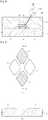
- FIG. 1is a plan view of the touch panel according to embodiment and FIG. 2 is a sectional view taken along line II-II of FIG. 1 .
- the touch panel 100includes a substrate 110, first and second electrodes 10 and 20 formed on the substrate 110, an insulating layer 30 formed at an intersection between the first and second electrodes 10 and 20 to insulate the first electrodes 10 from the second electrodes 20, and a protective member 120 for protecting the first and second electrodes 10 and 20 and the insulating layer 30.
- the first electrodes 10are drawn to the lower end of the substrate 110 by first wires 40 and the second electrodes 20 are drawn to the lower end of the substrate 110 by second wires 50.
- Terminal parts(not shown) can be formed on the first wires 40 or the second wires 50 and a flexible printed circuit board (FPCB) can be connected to the terminal parts such that the FPCB can be connected to an external circuit (not shown).
- FPCBflexible printed circuit board
- first and second electrodes 10 and 20are drawn to the lower end of the substrate 110, the embodiment is not limited thereto.
- the first electrodes 10may be drawn in opposition to the second electrodes 20. Otherwise, the first electrodes 10 may be drawn to the lower end of the substrate 110 and the second electrodes 10 may be drawn to the left and right sides of the substrate 110.
- the first and second electrodes 10 and 20may be drawn in various configurations such that the first and second electrodes 10 and 20 can be connected to the external circuit.
- the substrate 110, the first electrodes 10, the second electrodes 20, the insulating layer 30 and the first and second wires 40 and 50will be described in detail.
- the substrate 110may include various materials capable of supporting the first electrodes 10, the second electrodes 10, the insulating layer 30 and the first and second wires 40 and 50 formed on the substrate 110.
- the substrate 110may include a glass substrate.
- the first electrodes 10include a plurality of first sensor parts 12 for detecting whether an input device, such as a finger, makes contact with the first electrode 10 and first connection parts 14 for connecting the first sensor parts 12 with each other.
- the first connection parts 14connect the first sensor parts 12 in the first direction (X-axis direction in the drawing), so that the first electrodes 10 extend in the first direction.
- the second electrodes 20include a plurality of second sensor parts 22 for detecting whether an input device, such as a finger, makes contact with the second electrode 20 and second connection parts 24 for connecting the second sensor parts 22 with each other.
- the second connection parts 24connect the second sensor parts 22 in the second direction (Y-axis direction in the drawing) crossing the first direction so that the second electrodes 20 extend in the second direction.
- the first and second sensor parts 12 and 22 and the first and second connection parts 14 and 24may include transparent conductive materials such that electricity can be applied thereto without interfering with the transmission of the light.
- the transparent conductive materialsmay include various materials, such as indium tin oxide, indium zinc oxide, a carbon nano tube, a Ag nano wire and a conductive polymer.
- the first and second connection parts 14 and 24have resistance lower than that of the first and second sensor parts 12 and 22. This is because the manufacturing process and manufacturing method for the first and second connection parts 14 and 24 are different from the manufacturing process and manufacturing method for the first and second sensor parts 14 and 24.
- first and second connection parts 14 and 24may include materials having resistance lower than that of the first and second sensor parts 12 and 22 or the first and second connection parts 14 and 24 may have the thickness thicker than that of the first and second sensor parts 12 and 22 to lower the resistance of the first and second connection parts 14 and 24.
- first and second connection parts 14 and 24include materials different from materials of the first and second sensor parts 12 and 22, the first and second sensor parts 12 and 22 exclusively include transparent conductive materials and inevitable impurities.
- the first and second connection parts 14 and 24include at least one of a carbon nano tube (CNT), a nano wire and a conductive polymer as well as the transparent conductive materials.
- the first and second connection parts 14 and 24may include conductive materials including at least one of the CNT, the nano wire and the conductive polymer. The resistance of the first and second connection parts 14 and 24 may be lowered due to the CNT, the nano wire and the conductive polymer.
- the thickness of the first and second connection parts 14 and 24is different from the thickness of the first and second sensor parts 12 and 22, the thickness of the first and second connection parts 14 and 24 is thicker that the thickness of the first and second sensor parts 12 and 22, so that the resistance of the first and second connection parts 14 and 24 is lowered.
- the thickness of the first and second connection parts 14 and 24is thicker that the thickness of the first and second sensor parts 12 and 22 by 1.5 to 10 times.
- the thickness T2 of the second connection part 24 and the thickness T1 of the second sensor part 22are shown in the drawing, the first connection part 14 and the first sensor part 12 may have the above thickness.
- the thickness of the touch panel 100may be increased and the amount of materials for manufacturing the first and second connection parts 14 and 14 may be increased, so that the manufacturing cost may rise.
- the thicknessis set within the range of 1.5 to 10 times by taking the manufacturing cost into consideration.
- first and second connection parts 14 and 24have the resistance different from the resistance of the first and second sensor parts 12 and 22, the embodiment is not limited thereto. It is also possible to allow only the first connection part 14 to have the resistance lower than that of the first sensor part 12 or to allow only the second connection part 24 to have the resistance lower than that of the second sensor part 22.
- the insulation layer 30is positioned at the intersection between the first and second connection parts 14 and 24 in order to prevent the electric short between the first and second connection parts 14 and 24.
- the insulating layer 30may include a transparent insulating material capable of insulating the first connection part 14 from the second connection part 24.
- the insulating layer 30may include metal oxide, such as silicon oxide or resin, such as acryl.
- the first and second wires 40 and 50may include various materials capable of transferring electricity to the first and second electrodes 10 and 20, respectively.
- the first and second wires 40 and 50may include materials having superior electric conductivity, such as a metal.
- the protective member 120is aligned to cover the first and second electrodes 10 and 20, the insulating layer 30 and the first and second wires 40 and 50.
- the protective member 120may include various materials capable of protecting the first and second electrodes 10 and 20, and the insulating layer 30, and the embodiment is not limited thereto.
- capacitance differencemay occur at a region that comes into contact with the input device, so this region is detected as the contact position.
- the first and second connection parts 14 and 24have the relatively low resistance, so the resistance of the first and second electrodes 10 and 20 can be lowered.
- the electric stability and the touch sensitivity of the touch panel 100can be improved.
- FIG. 3is a sectional view of the touch panel according to the second embodiment.
- the touch panel 200includes a second connection part 24 having nano wires 24a.
- the nano wires 24aare connected to each other by a binder (not shown). Since the second connection part 24 includes the nano wires 24a, the second connection part 24 may have the superior optical and electric characteristics. In detail, the transparent degree and the transmission degree of the touch panel can be improved while lowering the resistance.
- the second connection part 24may include carbon nano tubes connected to each other by the binder.
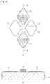
- FIG. 4is a sectional view of the touch panel according to the invention.
- the touch panel 300includes a second connection part 24.
- the second connection part 24may include at least one selected from the group consisting of a carbon nano tube, a nano wire, and a conductive polymer.
- the nano wires 24bare distributed in the conductive polymer 24c.
- the embodimentis not limited to the above.
- carbon nano tubesmay be distributed in the conductive polymer instead of the nano wires.
- FIGS. 5 to 8are plan and sectional views for explaining the method for manufacturing the touch panel according to the first embodiment.
- FIGS. 5(a) , 6(a) , 7(a) , and 8(a)are plan views showing the first electrode 10, the second electrode 20 and the insulating layer 30 formed in a region A of FIG. 1
- FIGS. 5(b) , 6(b) , 7(b) , and 8(b)are sectional views taken along line B-B shown in FIGS. 5(a) , 6(a) , 7(a) , and 8(a) .
- a plurality of first sensor parts 12 and a plurality of second sensor parts 22are formed on the substrate 110 by using the transparent conductive material.
- the transparent conductive materialmay include various materials, such as indium tin oxide or indium zinc oxide.
- the first and second sensor parts 12 and 22can be formed by depositing the transparent conductive material, for example, through a vacuum deposition process.
- the first connection part 14 connecting the first sensor parts 12 with each otheris formed by performing the printing process using a transparent conductive composition.
- the transparent conductive compositionmay include ink that contains the transparent conductive material.
- the transparent conductive compositionmay include a transparent conductive material, a binder, a dispersing agent, and an additive.
- Various materials generally known in the artmay be used as the binder, the dispersing agent and the additive.
- the first connection part 14is formed separately from the first sensor part 12, the first connection part 14 can be configured to have the resistance lower than that of the first sensor part 12.
- the first connection part 14may have a thickness thicker than that of the first sensor part 12 or a carbon nano tube, a nano wire or a conductive polymer may be added to a material (that is, the transparent conductive composition) for the first connection part 14.
- the first connection part 14is formed by patterning the transparent conductive material through the exposure/developing/etching processes, so the manufacturing process is complicated.
- the first connection part 14is formed through the printing process, so the process for manufacturing the first connection part 14 can be simplified.
- the printing processis advantageous to form a thick layer, so the printing process is suitable for forming the first connection part 14 having the thickness thicker than the first sensor part 12.
- the insulating layer 30 including the insulating materialis formed on the first connection part 14.
- the insulating layer 30can be formed through the printing process by using resin. Since the insulating layer 30 is formed through the printing process by using the resin, the insulating resistance of the insulating layer 30 can be improved, so that the reliability of the touch panel 100 can be enhanced. For instance, the insulating layer 30 may have the resistance of about 60GQ.
- the insulating layer 30may have the thickness T3 of about 0.1 ⁇ m to about 100 ⁇ m.
- the thickness T3 of the insulating layer 30may be changed by taking the printing characteristic of the second connection part 24 (see, FIG. 8 ) into consideration. If the thickness T3 of the insulating layer 30 is less than 0.1 ⁇ m, the insulating layer 30 may not sufficiently insulate the first connection part 14 from the second connection part 24. In addition, if the thickness T3 of the insulating layer 30 exceeds 100 ⁇ m, the thickness of the touch panel may be increased.
- the second connection part 24 connecting the second sensor parts 22 with each otheris formed on the insulating layer 30 by performing the printing process using the transparent conductive composition.
- the transparent conductive compositionmay include ink that contains the transparent conductive material.
- the transparent conductive compositionmay include a transparent conductive material, a binder, a dispersing agent, and an additive.
- Various materials generally known in the artmay be used as the binder, the dispersing agent and the additive.
- the transparent conductive compositionmay be ink including a nano wire, a solvent and a binder.
- inkcan be printed through the ink-jet scheme.
- the inkis sprayed from a slim nozzle. After the ink has been sprayed, the solvent is evaporated and the curing process is performed.
- the printingcan be achieved by repeating the above processes.
- the final materials constituting the second connection part 24may be the nano wire and the binder.
- the touch panel 200 shown in FIG. 3can be manufactured through the above printing process. At this time, the carbon nano tube may be used instead of the nano wire.
- the transparent conductive compositionmay be a paste including a nano wire and a conductive polymer.
- the transparent conductive compositionmay be the paste including the nano wires distributed in the conductive polymer.
- the pastecan be printed through the off-set printing scheme or the screen printing scheme.
- the off-set printing schemea paste is filled in an intaglio plate having a pattern and the primary transfer process is performed by using silicon rubber called a blanket. Then, the secondary transfer process is performed by closely attaching the blanket to the substrate formed with a conductive layer.
- the screen printing schemethe paste is formed on the screen having the pattern and then the paste is pressed by a squeeze, so that the paste is directly printed onto the substrate having the conductive layer through the screen having space sections.
- the second connection partmay include the nano wires distributed in the conductive polymer.
- the touch panel 300 shown in FIG. 4can be manufactured through the above printing process. At this time, the carbon nano tube may be used instead of the nano wire.
- the embodimentis not limited to the above, and the second connection part 24 can be formed through various printing schemes.
- the second connection part 24is formed separately from the second sensor part 22, the second connection part 24 can be configured to have the resistance lower than that of the second sensor part 22.
- the second connection part 24may have a thickness thicker than that of the second sensor part 22 or a carbon nano tube, a nano wire or a conductive polymer may be added to a material (that is, the transparent conductive composition) for the second connection part 24.
- the second connection part 24is formed by patterning the transparent conductive material, so the manufacturing process is complicated.
- the second connection part 24is formed through the printing process, so the process for manufacturing the second connection part 24 can be simplified.
- the printing processis advantageous to form a thick layer, so the printing process is suitable for forming the second connection part 24 having the thickness thicker than the second sensor part 22.
- a width W1 of the second connection part 24may be narrower than a width W2 of the insulating layer 30.
- the width W1 of the second connection part 24may be 1% to 99% based on the width W2 of the insulating layer 30.
- the protective member 120is formed, thereby manufacturing the touch panel shown in FIG. 2 .
- the first connection part 14, the insulating layer 30, and the second connection part 24can be sequentially formed through the printing process, so that the touch panel can be easily manufactured.
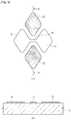
- FIGS. 9 to 11are plan and sectional views for explaining the method for manufacturing the touch panel according to the second embodiment.
- a plurality of first sensor parts 12, a first connection part 14 connecting the first sensor parts 12 with each other, and a plurality of second sensor parts 22are formed on the substrate 110. That is, the first connection part 14 is prepared as a pattern connected between the first sensor parts 12 without separately forming the first connection part 14, so that the manufacturing steps and the manufacturing time can be reduced.
- the insulating layer 30is formed on the first connection part 14.
- a second connection part 24 connecting the second sensor parts 22 with each otheris formed on the insulating layer.
Landscapes
- Engineering & Computer Science (AREA)
- General Engineering & Computer Science (AREA)
- Theoretical Computer Science (AREA)
- Human Computer Interaction (AREA)
- Physics & Mathematics (AREA)
- General Physics & Mathematics (AREA)
- Position Input By Displaying (AREA)
Description
- The disclosure relates to a touch panel and a method for manufacturing the same.
- Documents
US 2010/156810 A1 andUS 2009/160824 A1 disclose touch panels. US 2010/156810 A1 hereby discloses a touch screen assembly and method of manufacturing thereof that includes a single layer of conductive material is provided. The conductive material is configured to include a horizontal pattern and a vertical pattern of electrodes, with one of the patterns having gaps between the electrodes, such that the electrodes in the horizontal pattern do not come into direct contact with electrodes in the vertical pattern. To provide a connection between the electrodes separated by gaps in the interrupted pattern, an insulating material is placed onto the gaps over the uninterrupted pattern, and a printable and electrically conductive connector is positioned over the insulating material and functions to couple at least two electrodes together. In one embodiment, the conductive connector includes carbon nanotubes.US 2009/160824 A1 discloses a two-dimensional sensory structure for the capacitive touch panel is provided. The provided two-dimensional sensory structure includes a substrate having plural first metal structures and second metal structures on a first surface thereof, a dot-like insulating layer located on the substrate and composed of plural insulating dots, and an electrode layer located on the dot-like insulating layer and composed of plural conductive traces. The insulating dots are each corresponding to the first metal structures respectively, and thereby a first portion of the conductive traces arranged along a first direction are electrically connected to each other, and the conductive traces that are arranged along a second direction are electrically insulated therefrom.- Recently, touch panels are employed in various electronic appliances to allow a user to input data by touching an image displayed on a display device using an input device, such as a finger or a stylus.
- Such touch panels are mainly classified into resistive touch panels and capacitive touch panels. According to the resistive touch panel, an electrode is shorted as pressure is applied thereto from an input device so that a position is detected. According to the capacitive touch panel, capacitance between electrodes is varied as a finger touches the touch panel and a position is detected based on the capacitance variation.
- The performance of the resistive touch panel may be degraded if the resistive touch panel is repeatedly used for a long time, and scratch may be generated. For this reason, the capacitive touch panel has been spotlighted due to the superior durability and long life span.
- The embodiment provides a touch panel capable of improving electric stability and touch sensitivity and a method for manufacturing the same.
- A touch panel according to the invention is disclosed in claim 1.
- A method for manufacturing a touch panel according to a non-claimed embodiment includes the steps of forming a plurality of first sensor parts and second sensor parts including transparent conductive materials on a substrate; forming first connection parts connecting the first sensor parts with each other by printing a transparent conductive composition on the substrate; forming an insulating layer including an insulating material on the first connection parts; and forming second connection parts connecting the second sensor parts with each other on the insulating layer by using the transparent conductive composition.
- A method for manufacturing a touch panel according to another non-claimed embodiment includes the steps of forming a plurality of first sensor parts, a plurality of second sensor parts and first connection parts connecting the first sensor parts with each other on a substrate by using a transparent conductive material; forming an insulating layer by printing an insulating material on the first connection parts; and forming second connection parts connecting the second sensor parts with each other on the insulating layer by using a transparent conductive composition.
- According to the touch panel of the invention, resistance of the connection part is lower than resistance of the sensor part, so that resistance of the first electrode and/or the second electrode is lowered, thereby improving the electric stability and touch sensitivity.
- According to the invention, the connection part includes a nano wire or carbon nano tube, so superior optical and electric characteristics can be obtained. In detail, the transmittance and transparent degree of the touch panel can be improved while lowering resistance.
- According to the method for manufacturing the touch panel of a non-claimed embodiment, the connection part is formed through the printing process, so that the manufacturing process can be simplified. Since the connection part of the first electrode, the insulating layer and the connection part of the second electrode are sequentially formed through the printing process, the manufacturing process can be more simplified.
FIG. 1 is a plan view of a touch panel according to a non-claimed embodiment;FIG. 2 is a sectional view taken along line II-II ofFIG. 1 ;FIG. 3 is a sectional view of a touch panel according to a second non-claimed embodiment;FIG. 4 is a sectional view of a touch panel according to the invention;FIGS. 5 to 8 are plan and sectional views for explaining a method for manufacturing a touch panel according to the first non-claimed embodiment; andFIGS. 9 to 11 are plan and sectional views for explaining a method for manufacturing a touch panel according to the second non-claimed embodiment.- In the description it will be understood that, when a layer (or film), a region, a pattern, or a structure is referred to as being "on" or "under" another substrate, another layer (or film), another region, another pad, or another pattern, it can be "directly" or "indirectly" on the other substrate, layer (or film), region, pad, or pattern, or one or more intervening layers may also be present. Such a position of the layer has been described with reference to the drawings.
- The thickness and size of each layer shown in the drawings may be exaggerated, omitted or schematically drawn for the purpose of convenience or clarity. In addition, the size of elements does not utterly reflect an actual size.
- Hereinafter, the embodiments will be described in detail with reference to the accompanying drawings.
- First, a touch panel according to the embodiment will be described in detail with reference to
FIGS. 1 and 2 . FIG. 1 is a plan view of the touch panel according to embodiment andFIG. 2 is a sectional view taken along line II-II ofFIG. 1 .- Referring to
FIG. 1 , thetouch panel 100 according to the embodiment includes asubstrate 110, first andsecond electrodes substrate 110, aninsulating layer 30 formed at an intersection between the first andsecond electrodes first electrodes 10 from thesecond electrodes 20, and aprotective member 120 for protecting the first andsecond electrodes insulating layer 30. - The
first electrodes 10 are drawn to the lower end of thesubstrate 110 byfirst wires 40 and thesecond electrodes 20 are drawn to the lower end of thesubstrate 110 bysecond wires 50. Terminal parts (not shown) can be formed on thefirst wires 40 or thesecond wires 50 and a flexible printed circuit board (FPCB) can be connected to the terminal parts such that the FPCB can be connected to an external circuit (not shown). - Although it has been described and illustrated that the first and
second electrodes substrate 110, the embodiment is not limited thereto. Thefirst electrodes 10 may be drawn in opposition to thesecond electrodes 20. Otherwise, thefirst electrodes 10 may be drawn to the lower end of thesubstrate 110 and thesecond electrodes 10 may be drawn to the left and right sides of thesubstrate 110. In addition, the first andsecond electrodes second electrodes - Hereinafter, the
substrate 110, thefirst electrodes 10, thesecond electrodes 20, theinsulating layer 30 and the first andsecond wires - The
substrate 110 may include various materials capable of supporting thefirst electrodes 10, thesecond electrodes 10, theinsulating layer 30 and the first andsecond wires substrate 110. For instance, thesubstrate 110 may include a glass substrate. - The
first electrodes 10 include a plurality offirst sensor parts 12 for detecting whether an input device, such as a finger, makes contact with thefirst electrode 10 andfirst connection parts 14 for connecting thefirst sensor parts 12 with each other. Thefirst connection parts 14 connect thefirst sensor parts 12 in the first direction (X-axis direction in the drawing), so that thefirst electrodes 10 extend in the first direction. - Similarly to the
first electrodes 10, thesecond electrodes 20 include a plurality ofsecond sensor parts 22 for detecting whether an input device, such as a finger, makes contact with thesecond electrode 20 andsecond connection parts 24 for connecting thesecond sensor parts 22 with each other. Thesecond connection parts 24 connect thesecond sensor parts 22 in the second direction (Y-axis direction in the drawing) crossing the first direction so that thesecond electrodes 20 extend in the second direction. - The first and
second sensor parts second connection parts - According to the present embodiment, the first and
second connection parts second sensor parts second connection parts second sensor parts - For instance, the first and
second connection parts second sensor parts second connection parts second sensor parts second connection parts - In the case that the first and
second connection parts second sensor parts second sensor parts second connection parts second connection parts second connection parts - Referring to
FIG. 2 , in the case that the thickness of the first andsecond connection parts second sensor parts second connection parts second sensor parts second connection parts - For instance, the thickness of the first and
second connection parts second sensor parts second connection part 24 and the thickness T1 of thesecond sensor part 22 are shown in the drawing, thefirst connection part 14 and thefirst sensor part 12 may have the above thickness. - If the first and
second connection parts second sensor parts second connection parts second connection parts second sensor parts touch panel 100 may be increased and the amount of materials for manufacturing the first andsecond connection parts - Although it has been described and illustrated that the first and
second connection parts second sensor parts first connection part 14 to have the resistance lower than that of thefirst sensor part 12 or to allow only thesecond connection part 24 to have the resistance lower than that of thesecond sensor part 22. - The
insulation layer 30 is positioned at the intersection between the first andsecond connection parts second connection parts layer 30 may include a transparent insulating material capable of insulating thefirst connection part 14 from thesecond connection part 24. For instance, the insulatinglayer 30 may include metal oxide, such as silicon oxide or resin, such as acryl. - The first and
second wires second electrodes second wires - The
protective member 120 is aligned to cover the first andsecond electrodes layer 30 and the first andsecond wires protective member 120 may include various materials capable of protecting the first andsecond electrodes layer 30, and the embodiment is not limited thereto. - If the input device, such as the finger, makes contact with the
touch panel 100, capacitance difference may occur at a region that comes into contact with the input device, so this region is detected as the contact position. - In the case of the
touch panel 100 having the above structure, the first andsecond connection parts second electrodes touch panel 100 can be improved. - Hereinafter, the touch panel according to the second embodiment will be described with reference to
FIG. 3 . Description about the elements and structures that have been described in the first embodiment will be omitted in order to clarify and simplify the explanation. FIG. 3 is a sectional view of the touch panel according to the second embodiment.- Referring to
FIG. 3 , thetouch panel 200 according to the second embodiment includes asecond connection part 24 havingnano wires 24a. Thenano wires 24a are connected to each other by a binder (not shown). Since thesecond connection part 24 includes thenano wires 24a, thesecond connection part 24 may have the superior optical and electric characteristics. In detail, the transparent degree and the transmission degree of the touch panel can be improved while lowering the resistance. - However, the embodiment is not limited to the above. For instance, the
second connection part 24 may include carbon nano tubes connected to each other by the binder. - Hereinafter, the touch panel according to the invention will be described with reference to
FIG. 4 . FIG. 4 is a sectional view of the touch panel according to the invention.- Referring to
FIG. 4 , thetouch panel 300 according to the invention includes asecond connection part 24. Thesecond connection part 24 may include at least one selected from the group consisting of a carbon nano tube, a nano wire, and a conductive polymer. - In detail, in the
second connection part 24, thenano wires 24b are distributed in theconductive polymer 24c. However, the embodiment is not limited to the above. For instance, carbon nano tubes may be distributed in the conductive polymer instead of the nano wires. - Hereinafter, the method for manufacturing the touch panel according to the first embodiment will be described with reference to
FIGS. 5 to 8 . FIGS. 5 to 8 are plan and sectional views for explaining the method for manufacturing the touch panel according to the first embodiment. In detail,FIGS. 5(a) ,6(a) ,7(a) , and8(a) are plan views showing thefirst electrode 10, thesecond electrode 20 and the insulatinglayer 30 formed in a region A ofFIG. 1 , andFIGS. 5(b) ,6(b) ,7(b) , and8(b) are sectional views taken along line B-B shown inFIGS. 5(a) ,6(a) ,7(a) , and8(a) .- First, as shown in
FIG. 5 , a plurality offirst sensor parts 12 and a plurality ofsecond sensor parts 22 are formed on thesubstrate 110 by using the transparent conductive material. The transparent conductive material may include various materials, such as indium tin oxide or indium zinc oxide. The first andsecond sensor parts - Then, as shown in
FIG. 6 , thefirst connection part 14 connecting thefirst sensor parts 12 with each other is formed by performing the printing process using a transparent conductive composition. - The transparent conductive composition may include ink that contains the transparent conductive material. The transparent conductive composition may include a transparent conductive material, a binder, a dispersing agent, and an additive. Various materials generally known in the art may be used as the binder, the dispersing agent and the additive.
- Since the
first connection part 14 is formed separately from thefirst sensor part 12, thefirst connection part 14 can be configured to have the resistance lower than that of thefirst sensor part 12. To this end, thefirst connection part 14 may have a thickness thicker than that of thefirst sensor part 12 or a carbon nano tube, a nano wire or a conductive polymer may be added to a material (that is, the transparent conductive composition) for thefirst connection part 14. - According to the related art, after depositing the transparent conductive material, the
first connection part 14 is formed by patterning the transparent conductive material through the exposure/developing/etching processes, so the manufacturing process is complicated. However, according to the embodiment, thefirst connection part 14 is formed through the printing process, so the process for manufacturing thefirst connection part 14 can be simplified. In particular, the printing process is advantageous to form a thick layer, so the printing process is suitable for forming thefirst connection part 14 having the thickness thicker than thefirst sensor part 12. - After that, as shown in
FIG. 7 , the insulatinglayer 30 including the insulating material is formed on thefirst connection part 14. The insulatinglayer 30 can be formed through the printing process by using resin. Since the insulatinglayer 30 is formed through the printing process by using the resin, the insulating resistance of the insulatinglayer 30 can be improved, so that the reliability of thetouch panel 100 can be enhanced. For instance, the insulatinglayer 30 may have the resistance of about 60GQ. - The insulating
layer 30 may have the thickness T3 of about 0.1µm to about 100µm. The thickness T3 of the insulatinglayer 30 may be changed by taking the printing characteristic of the second connection part 24 (see,FIG. 8 ) into consideration. If the thickness T3 of the insulatinglayer 30 is less than 0.1µm, the insulatinglayer 30 may not sufficiently insulate thefirst connection part 14 from thesecond connection part 24. In addition, if the thickness T3 of the insulatinglayer 30 exceeds 100µm, the thickness of the touch panel may be increased. - Then, as shown in
FIG. 8 , thesecond connection part 24 connecting thesecond sensor parts 22 with each other is formed on the insulatinglayer 30 by performing the printing process using the transparent conductive composition. - The transparent conductive composition may include ink that contains the transparent conductive material. The transparent conductive composition may include a transparent conductive material, a binder, a dispersing agent, and an additive. Various materials generally known in the art may be used as the binder, the dispersing agent and the additive.
- For instance, the transparent conductive composition may be ink including a nano wire, a solvent and a binder. Such ink can be printed through the ink-jet scheme. According to the ink-jet scheme, the ink is sprayed from a slim nozzle. After the ink has been sprayed, the solvent is evaporated and the curing process is performed. The printing can be achieved by repeating the above processes.
- Thus, the final materials constituting the
second connection part 24 may be the nano wire and the binder. Thetouch panel 200 shown inFIG. 3 can be manufactured through the above printing process. At this time, the carbon nano tube may be used instead of the nano wire. - In addition, the transparent conductive composition may be a paste including a nano wire and a conductive polymer. In detail, the transparent conductive composition may be the paste including the nano wires distributed in the conductive polymer. The paste can be printed through the off-set printing scheme or the screen printing scheme. According to the off-set printing scheme, a paste is filled in an intaglio plate having a pattern and the primary transfer process is performed by using silicon rubber called a blanket. Then, the secondary transfer process is performed by closely attaching the blanket to the substrate formed with a conductive layer. According to the screen printing scheme, the paste is formed on the screen having the pattern and then the paste is pressed by a squeeze, so that the paste is directly printed onto the substrate having the conductive layer through the screen having space sections.
- Therefore, the second connection part may include the nano wires distributed in the conductive polymer. The
touch panel 300 shown inFIG. 4 can be manufactured through the above printing process. At this time, the carbon nano tube may be used instead of the nano wire. - However, the embodiment is not limited to the above, and the
second connection part 24 can be formed through various printing schemes. - Since the
second connection part 24 is formed separately from thesecond sensor part 22, thesecond connection part 24 can be configured to have the resistance lower than that of thesecond sensor part 22. To this end, thesecond connection part 24 may have a thickness thicker than that of thesecond sensor part 22 or a carbon nano tube, a nano wire or a conductive polymer may be added to a material (that is, the transparent conductive composition) for thesecond connection part 24. - According to the related art, after depositing the transparent conductive material, the
second connection part 24 is formed by patterning the transparent conductive material, so the manufacturing process is complicated. However, according to the embodiment, thesecond connection part 24 is formed through the printing process, so the process for manufacturing thesecond connection part 24 can be simplified. In particular, the printing process is advantageous to form a thick layer, so the printing process is suitable for forming thesecond connection part 24 having the thickness thicker than thesecond sensor part 22. - A width W1 of the
second connection part 24 may be narrower than a width W2 of the insulatinglayer 30. In detail, the width W1 of thesecond connection part 24 may be 1% to 99% based on the width W2 of the insulatinglayer 30. Thus, the electric short can be prevented between the first andsecond connection parts - After that, the
protective member 120 is formed, thereby manufacturing the touch panel shown inFIG. 2 . - According to the present embodiment, the
first connection part 14, the insulatinglayer 30, and thesecond connection part 24 can be sequentially formed through the printing process, so that the touch panel can be easily manufactured. - Hereinafter, the method for manufacturing the touch panel according to the second embodiment will be described with reference to
FIGS. 9 to 11 . FIGS. 9 to 11 are plan and sectional views for explaining the method for manufacturing the touch panel according to the second embodiment.- First, as shown in
FIG. 9 , a plurality offirst sensor parts 12, afirst connection part 14 connecting thefirst sensor parts 12 with each other, and a plurality ofsecond sensor parts 22 are formed on thesubstrate 110. That is, thefirst connection part 14 is prepared as a pattern connected between thefirst sensor parts 12 without separately forming thefirst connection part 14, so that the manufacturing steps and the manufacturing time can be reduced. - Then, as shown in
FIG. 10 , the insulatinglayer 30 is formed on thefirst connection part 14. - After that, as shown in
FIG. 11 , asecond connection part 24 connecting thesecond sensor parts 22 with each other is formed on the insulating layer.
Claims (1)
- A touch panel (100) comprising:a substrate (110);a first electrode (10) formed on the substrate (110) in a first direction and including a plurality of first sensor parts (12) and first connection parts (14) connecting the first sensor parts (12) with each other;an insulating layer (30) formed on the first connection parts (14) of the first electrode (10); anda second electrode (20) formed in a second direction crossing the first direction while being insulated from the first electrode (10) and including a plurality of second sensor parts (22) and second connection parts (24) connecting the sensor parts with each other,the first connection parts (14) being in direct contact with first sensor parts (12) and the second connection parts (24) being in direct contact with second sensor parts (22),the connection parts (14, 24) having resistance lower than resistance of the sensor parts (12, 22) in at least one of the first and second electrodes (10, 20),wherein the sensor parts (12, 22) and the first connection parts (14) include transparent conductive materials,wherein the transparent conductive materials include indium tin oxide or indium zinc oxide,characterized in that the second connection parts (24) include a conductive polymer, wherein either nano wires or carbon nano tubes are distributed in the conductive polymer,wherein the insulating layer (30) has a thickness in a range of 0.1 µm to 100 µm,wherein each first connection part (14) is thicker than each first sensor part (12) and each second connection part (24) is thicker than each second sensor part (22), the first connection parts (14) being thicker than the first sensor parts (12) by 1.5 to 10 times and the second connection part (24) being thicker than the second sensor parts (22) by 1.5 to 10 times, andwherein a width of the second connection parts (24) is 1% to 99% based on a width of the insulating layer (30).
Applications Claiming Priority (3)
| Application Number | Priority Date | Filing Date | Title |
|---|---|---|---|
| KR1020100067816AKR101105692B1 (en) | 2010-07-14 | 2010-07-14 | Method for manufacturing planar member for touch panel |
| KR1020100071124AKR20120009181A (en) | 2010-07-22 | 2010-07-22 | Touch panel and manufacturing method thereof |
| PCT/KR2011/005163WO2012008759A2 (en) | 2010-07-14 | 2011-07-13 | Touch panel and method for manufacturing the same |
Publications (3)
| Publication Number | Publication Date |
|---|---|
| EP2593852A2 EP2593852A2 (en) | 2013-05-22 |
| EP2593852A4 EP2593852A4 (en) | 2016-10-05 |
| EP2593852B1true EP2593852B1 (en) | 2020-12-16 |
Family
ID=45469927
Family Applications (1)
| Application Number | Title | Priority Date | Filing Date |
|---|---|---|---|
| EP11807044.0AActiveEP2593852B1 (en) | 2010-07-14 | 2011-07-13 | Touch panel and method for manufacturing the same |
Country Status (6)
| Country | Link |
|---|---|
| US (1) | US9535543B2 (en) |
| EP (1) | EP2593852B1 (en) |
| JP (2) | JP2013531317A (en) |
| CN (1) | CN103003781B (en) |
| TW (1) | TWI557606B (en) |
| WO (1) | WO2012008759A2 (en) |
Families Citing this family (17)
| Publication number | Priority date | Publication date | Assignee | Title |
|---|---|---|---|---|
| JP2014211663A (en)* | 2011-09-02 | 2014-11-13 | シャープ株式会社 | Touch panel and method of manufacturing touch panel |
| US20140000944A1 (en)* | 2012-07-02 | 2014-01-02 | Panasonic Corporation | Touch panel |
| KR101975536B1 (en)* | 2012-07-30 | 2019-05-08 | 삼성디스플레이 주식회사 | flexible touch screen panel |
| TW201514802A (en)* | 2013-07-16 | 2015-04-16 | Lg Innotek Co Ltd | Touch window and touch device including the same |
| KR20150029507A (en)* | 2013-09-10 | 2015-03-18 | 미래나노텍(주) | Touch screen sensor, Touch screen panel of electrostatic capacitive type and image display device |
| WO2015053062A1 (en)* | 2013-10-09 | 2015-04-16 | 株式会社ノリタケカンパニーリミテド | Capacitive touch switch panel |
| KR102207143B1 (en) | 2013-11-06 | 2021-01-25 | 삼성디스플레이 주식회사 | Touch panel and manufacturing method thereof |
| KR101626822B1 (en)* | 2013-11-20 | 2016-06-02 | 신화인터텍 주식회사 | Transparent electrode substrate and method of fabricating the same |
| KR101626821B1 (en)* | 2013-11-20 | 2016-06-02 | 신화인터텍 주식회사 | Transparent electrode substrate and method of fabricating the same |
| KR101577198B1 (en) | 2014-04-28 | 2015-12-14 | 신화인터텍 주식회사 | Transparent electrode substrate and method of fabricating the same |
| KR101931897B1 (en)* | 2015-01-16 | 2018-12-21 | 알프스 덴키 가부시키가이샤 | Capacitive sensor |
| KR102285456B1 (en)* | 2015-02-10 | 2021-08-03 | 동우 화인켐 주식회사 | Conductive pattern |
| CN104679340A (en)* | 2015-03-20 | 2015-06-03 | 合肥鑫晟光电科技有限公司 | Touch substrate and display device |
| CN106293250A (en)* | 2016-09-09 | 2017-01-04 | 合肥鑫晟光电科技有限公司 | Touch control unit and manufacture method, touch-control display panel |
| CN108710452B (en)* | 2018-04-27 | 2021-06-11 | 业成科技(成都)有限公司 | Touch panel and touch display device using same |
| KR102664393B1 (en)* | 2018-08-16 | 2024-05-08 | 삼성전자주식회사 | low resistance fingertip sensor and the method of making the same |
| CN116774861A (en)* | 2022-03-10 | 2023-09-19 | 京东方科技集团股份有限公司 | Touch substrate, touch display panel and display device |
Family Cites Families (35)
| Publication number | Priority date | Publication date | Assignee | Title |
|---|---|---|---|---|
| WO2003083424A1 (en)* | 2002-03-29 | 2003-10-09 | Sanyo Electric Co., Ltd. | Pressure sensor and method for fabricating the same |
| JP2004196912A (en) | 2002-12-17 | 2004-07-15 | Toyobo Co Ltd | Conductive coating |
| US8018568B2 (en)* | 2006-10-12 | 2011-09-13 | Cambrios Technologies Corporation | Nanowire-based transparent conductors and applications thereof |
| KR100907512B1 (en) | 2006-12-29 | 2009-07-14 | (주)탑나노시스 | Method of forming a touch panel and a conductive layer of the touch panel |
| TW200842681A (en) | 2007-04-27 | 2008-11-01 | Tpk Touch Solutions Inc | Touch pattern structure of a capacitive touch panel |
| JP4506785B2 (en) | 2007-06-14 | 2010-07-21 | エプソンイメージングデバイス株式会社 | Capacitive input device |
| JP5033740B2 (en)* | 2007-10-26 | 2012-09-26 | 帝人株式会社 | Transparent conductive laminate and touch panel |
| KR20090058072A (en)* | 2007-12-04 | 2009-06-09 | 주식회사 협진아이엔씨 | One layer capacitive touch screen and manufacturing method |
| TWM344544U (en) | 2007-12-25 | 2008-11-11 | Cando Corp | Sensory structure of touch panel |
| JP2009205924A (en)* | 2008-02-27 | 2009-09-10 | Kuraray Co Ltd | Transparent conductive film, transparent conductive member, silver nanowire dispersion and transparent conductive film manufacturing method |
| JP2009265748A (en) | 2008-04-22 | 2009-11-12 | Hitachi Displays Ltd | Display with touch panel |
| US20090309850A1 (en) | 2008-06-16 | 2009-12-17 | Kai-Ti Yang | Capacitive touch panel |
| JP4720857B2 (en) | 2008-06-18 | 2011-07-13 | ソニー株式会社 | Capacitance type input device and display device with input function |
| US8629842B2 (en) | 2008-07-11 | 2014-01-14 | Samsung Display Co., Ltd. | Organic light emitting display device |
| US9342176B2 (en) | 2008-07-21 | 2016-05-17 | Samsung Display Co., Ltd. | Organic light emitting display device |
| JP5178379B2 (en) | 2008-07-31 | 2013-04-10 | 株式会社ジャパンディスプレイイースト | Display device |
| CN102112950B (en) | 2008-09-12 | 2015-01-28 | 奥博特瑞克斯株式会社 | Capacitive touch panel, display device, and method for manufacturing capacitive touch panel |
| JP5189449B2 (en) | 2008-09-30 | 2013-04-24 | 富士フイルム株式会社 | Metal nanowire-containing composition and transparent conductor |
| JP5262666B2 (en)* | 2008-12-12 | 2013-08-14 | Smk株式会社 | Capacitive touch panel |
| JP2010146283A (en)* | 2008-12-18 | 2010-07-01 | Toshiba Mobile Display Co Ltd | Method of manufacturing capacitance type touch panel |
| US8274486B2 (en)* | 2008-12-22 | 2012-09-25 | Flextronics Ap, Llc | Diamond pattern on a single layer |
| JP5289033B2 (en)* | 2008-12-24 | 2013-09-11 | 三洋電機株式会社 | Solid electrolytic capacitor |
| JP2010160670A (en) | 2009-01-08 | 2010-07-22 | Seiko Epson Corp | Method for manufacturing touch panel, touch panel, display and electronic apparatus |
| TWM381834U (en) | 2009-05-19 | 2010-06-01 | Dagi Corp Co Ltd | Capacitor-type touch device |
| TWI497157B (en)* | 2009-06-19 | 2015-08-21 | Tpk Touch Solutions Inc | Touch ips liquid crystal display |
| CN201429838Y (en) | 2009-06-25 | 2010-03-24 | 深圳莱宝高科技股份有限公司 | Capacitive touch screen |
| JP2011022659A (en)* | 2009-07-13 | 2011-02-03 | Shin Etsu Polymer Co Ltd | Capacitance-type input device |
| JP5473460B2 (en)* | 2009-07-30 | 2014-04-16 | 京セラ株式会社 | Input device and display device including the input device |
| CN101989136B (en)* | 2009-08-07 | 2012-12-19 | 清华大学 | Touch screen and display device |
| JP2011039759A (en)* | 2009-08-11 | 2011-02-24 | Seiko Epson Corp | Touch panel device, method for manufacturing the same, display, and electronic equipment |
| CN201489507U (en) | 2009-08-21 | 2010-05-26 | 深圳莱宝高科技股份有限公司 | Capacitive touch screen wiring |
| JP5677028B2 (en)* | 2009-10-23 | 2015-02-25 | 京セラ株式会社 | Display device |
| TWM383779U (en) | 2009-11-02 | 2010-07-01 | Cheung Wing Technology Co Ltd | Structure of capacitive multi-touch touch panel |
| TWM378429U (en) | 2009-12-02 | 2010-04-11 | Young Fast Optoelectronics Co | Touch panel |
| JP2011180806A (en) | 2010-03-01 | 2011-09-15 | Hitachi Displays Ltd | Touch panel and display device |
- 2011
- 2011-07-13CNCN201180034679.0Apatent/CN103003781B/ennot_activeExpired - Fee Related
- 2011-07-13EPEP11807044.0Apatent/EP2593852B1/enactiveActive
- 2011-07-13JPJP2013519591Apatent/JP2013531317A/enactivePending
- 2011-07-13USUS13/810,073patent/US9535543B2/ennot_activeExpired - Fee Related
- 2011-07-13WOPCT/KR2011/005163patent/WO2012008759A2/enactiveApplication Filing
- 2011-07-14TWTW100124904Apatent/TWI557606B/ennot_activeIP Right Cessation
- 2014
- 2014-04-14JPJP2014082652Apatent/JP2014149861A/enactivePending
Non-Patent Citations (1)
| Title |
|---|
| None* |
Also Published As
| Publication number | Publication date |
|---|---|
| US9535543B2 (en) | 2017-01-03 |
| WO2012008759A3 (en) | 2012-04-05 |
| TWI557606B (en) | 2016-11-11 |
| US20130181944A1 (en) | 2013-07-18 |
| JP2013531317A (en) | 2013-08-01 |
| EP2593852A4 (en) | 2016-10-05 |
| WO2012008759A2 (en) | 2012-01-19 |
| JP2014149861A (en) | 2014-08-21 |
| CN103003781A (en) | 2013-03-27 |
| EP2593852A2 (en) | 2013-05-22 |
| TW201214228A (en) | 2012-04-01 |
| CN103003781B (en) | 2016-08-17 |
Similar Documents
| Publication | Publication Date | Title |
|---|---|---|
| EP2593852B1 (en) | Touch panel and method for manufacturing the same | |
| EP2871558B1 (en) | Touch window and touch device including the same | |
| EP2652583B1 (en) | Touch panel, method for manufacturing the same, and liquid crystal display device including the touch panel | |
| US9857923B2 (en) | Touch panel including an elastic intermediate layer | |
| US8212791B2 (en) | Protection panel with touch input function for display window of electronic device, and electronic device | |
| EP2827231B1 (en) | Touch window and display including the same | |
| US20110210935A1 (en) | Sensory structure of capacitive touch panel and capacitive touch panel having the same | |
| EP2905683A1 (en) | Capacitive touch window | |
| US20100053114A1 (en) | Touch panel apparatus and method for manufacturing the same | |
| CN101763191A (en) | Diamond pattern on a single layer | |
| CN104635983A (en) | Touch switch | |
| TW201102702A (en) | Capacitive touch panel | |
| KR20120031797A (en) | Touch screen panel and touch screen assembly including the same | |
| CN101882044A (en) | Electronic device | |
| WO2013085227A1 (en) | Electrode pattern of touch panel and method of manufacturing the same | |
| KR101765950B1 (en) | Touch panel | |
| KR20150072838A (en) | Touch panel | |
| KR101303707B1 (en) | A Cover Window-integrated Touch Screen Panel And A Method Of The Same | |
| KR20120023288A (en) | Touch panel and method for manufacturing the same | |
| EP2899616A1 (en) | Touch window | |
| KR20120009181A (en) | Touch panel and manufacturing method thereof | |
| JP2005190125A (en) | Panel type input device | |
| KR102008736B1 (en) | Touch panel and method for driving the same | |
| KR101365037B1 (en) | Electrode structure for touch panel and method for fabricating the same | |
| KR20150087548A (en) | Touch panel |
Legal Events
| Date | Code | Title | Description |
|---|---|---|---|
| PUAI | Public reference made under article 153(3) epc to a published international application that has entered the european phase | Free format text:ORIGINAL CODE: 0009012 | |
| 17P | Request for examination filed | Effective date:20130123 | |
| AK | Designated contracting states | Kind code of ref document:A2 Designated state(s):AL AT BE BG CH CY CZ DE DK EE ES FI FR GB GR HR HU IE IS IT LI LT LU LV MC MK MT NL NO PL PT RO RS SE SI SK SM TR | |
| DAX | Request for extension of the european patent (deleted) | ||
| REG | Reference to a national code | Ref country code:DE Ref legal event code:R079 Ref document number:602011069672 Country of ref document:DE Free format text:PREVIOUS MAIN CLASS: G06F0003041000 Ipc:G06F0003044000 | |
| A4 | Supplementary search report drawn up and despatched | Effective date:20160907 | |
| RIC1 | Information provided on ipc code assigned before grant | Ipc:G06F 3/044 20060101AFI20160901BHEP | |
| RAP1 | Party data changed (applicant data changed or rights of an application transferred) | Owner name:LG INNOTEK CO., LTD. | |
| STAA | Information on the status of an ep patent application or granted ep patent | Free format text:STATUS: EXAMINATION IS IN PROGRESS | |
| 17Q | First examination report despatched | Effective date:20190806 | |
| GRAP | Despatch of communication of intention to grant a patent | Free format text:ORIGINAL CODE: EPIDOSNIGR1 | |
| STAA | Information on the status of an ep patent application or granted ep patent | Free format text:STATUS: GRANT OF PATENT IS INTENDED | |
| INTG | Intention to grant announced | Effective date:20200731 | |
| GRAS | Grant fee paid | Free format text:ORIGINAL CODE: EPIDOSNIGR3 | |
| GRAA | (expected) grant | Free format text:ORIGINAL CODE: 0009210 | |
| STAA | Information on the status of an ep patent application or granted ep patent | Free format text:STATUS: THE PATENT HAS BEEN GRANTED | |
| AK | Designated contracting states | Kind code of ref document:B1 Designated state(s):AL AT BE BG CH CY CZ DE DK EE ES FI FR GB GR HR HU IE IS IT LI LT LU LV MC MK MT NL NO PL PT RO RS SE SI SK SM TR | |
| REG | Reference to a national code | Ref country code:GB Ref legal event code:FG4D | |
| REG | Reference to a national code | Ref country code:IE Ref legal event code:FG4D | |
| REG | Reference to a national code | Ref country code:DE Ref legal event code:R096 Ref document number:602011069672 Country of ref document:DE | |
| REG | Reference to a national code | Ref country code:AT Ref legal event code:REF Ref document number:1346194 Country of ref document:AT Kind code of ref document:T Effective date:20210115 | |
| PG25 | Lapsed in a contracting state [announced via postgrant information from national office to epo] | Ref country code:GR Free format text:LAPSE BECAUSE OF FAILURE TO SUBMIT A TRANSLATION OF THE DESCRIPTION OR TO PAY THE FEE WITHIN THE PRESCRIBED TIME-LIMIT Effective date:20210317 Ref country code:NO Free format text:LAPSE BECAUSE OF FAILURE TO SUBMIT A TRANSLATION OF THE DESCRIPTION OR TO PAY THE FEE WITHIN THE PRESCRIBED TIME-LIMIT Effective date:20210316 Ref country code:RS Free format text:LAPSE BECAUSE OF FAILURE TO SUBMIT A TRANSLATION OF THE DESCRIPTION OR TO PAY THE FEE WITHIN THE PRESCRIBED TIME-LIMIT Effective date:20201216 Ref country code:FI Free format text:LAPSE BECAUSE OF FAILURE TO SUBMIT A TRANSLATION OF THE DESCRIPTION OR TO PAY THE FEE WITHIN THE PRESCRIBED TIME-LIMIT Effective date:20201216 | |
| REG | Reference to a national code | Ref country code:AT Ref legal event code:MK05 Ref document number:1346194 Country of ref document:AT Kind code of ref document:T Effective date:20201216 | |
| REG | Reference to a national code | Ref country code:NL Ref legal event code:MP Effective date:20201216 | |
| PG25 | Lapsed in a contracting state [announced via postgrant information from national office to epo] | Ref country code:LV Free format text:LAPSE BECAUSE OF FAILURE TO SUBMIT A TRANSLATION OF THE DESCRIPTION OR TO PAY THE FEE WITHIN THE PRESCRIBED TIME-LIMIT Effective date:20201216 Ref country code:SE Free format text:LAPSE BECAUSE OF FAILURE TO SUBMIT A TRANSLATION OF THE DESCRIPTION OR TO PAY THE FEE WITHIN THE PRESCRIBED TIME-LIMIT Effective date:20201216 Ref country code:BG Free format text:LAPSE BECAUSE OF FAILURE TO SUBMIT A TRANSLATION OF THE DESCRIPTION OR TO PAY THE FEE WITHIN THE PRESCRIBED TIME-LIMIT Effective date:20210316 | |
| PG25 | Lapsed in a contracting state [announced via postgrant information from national office to epo] | Ref country code:NL Free format text:LAPSE BECAUSE OF FAILURE TO SUBMIT A TRANSLATION OF THE DESCRIPTION OR TO PAY THE FEE WITHIN THE PRESCRIBED TIME-LIMIT Effective date:20201216 Ref country code:HR Free format text:LAPSE BECAUSE OF FAILURE TO SUBMIT A TRANSLATION OF THE DESCRIPTION OR TO PAY THE FEE WITHIN THE PRESCRIBED TIME-LIMIT Effective date:20201216 | |
| REG | Reference to a national code | Ref country code:LT Ref legal event code:MG9D | |
| PG25 | Lapsed in a contracting state [announced via postgrant information from national office to epo] | Ref country code:SK Free format text:LAPSE BECAUSE OF FAILURE TO SUBMIT A TRANSLATION OF THE DESCRIPTION OR TO PAY THE FEE WITHIN THE PRESCRIBED TIME-LIMIT Effective date:20201216 Ref country code:PT Free format text:LAPSE BECAUSE OF FAILURE TO SUBMIT A TRANSLATION OF THE DESCRIPTION OR TO PAY THE FEE WITHIN THE PRESCRIBED TIME-LIMIT Effective date:20210416 Ref country code:RO Free format text:LAPSE BECAUSE OF FAILURE TO SUBMIT A TRANSLATION OF THE DESCRIPTION OR TO PAY THE FEE WITHIN THE PRESCRIBED TIME-LIMIT Effective date:20201216 Ref country code:LT Free format text:LAPSE BECAUSE OF FAILURE TO SUBMIT A TRANSLATION OF THE DESCRIPTION OR TO PAY THE FEE WITHIN THE PRESCRIBED TIME-LIMIT Effective date:20201216 Ref country code:SM Free format text:LAPSE BECAUSE OF FAILURE TO SUBMIT A TRANSLATION OF THE DESCRIPTION OR TO PAY THE FEE WITHIN THE PRESCRIBED TIME-LIMIT Effective date:20201216 Ref country code:CZ Free format text:LAPSE BECAUSE OF FAILURE TO SUBMIT A TRANSLATION OF THE DESCRIPTION OR TO PAY THE FEE WITHIN THE PRESCRIBED TIME-LIMIT Effective date:20201216 Ref country code:EE Free format text:LAPSE BECAUSE OF FAILURE TO SUBMIT A TRANSLATION OF THE DESCRIPTION OR TO PAY THE FEE WITHIN THE PRESCRIBED TIME-LIMIT Effective date:20201216 | |
| PG25 | Lapsed in a contracting state [announced via postgrant information from national office to epo] | Ref country code:AT Free format text:LAPSE BECAUSE OF FAILURE TO SUBMIT A TRANSLATION OF THE DESCRIPTION OR TO PAY THE FEE WITHIN THE PRESCRIBED TIME-LIMIT Effective date:20201216 Ref country code:PL Free format text:LAPSE BECAUSE OF FAILURE TO SUBMIT A TRANSLATION OF THE DESCRIPTION OR TO PAY THE FEE WITHIN THE PRESCRIBED TIME-LIMIT Effective date:20201216 | |
| REG | Reference to a national code | Ref country code:DE Ref legal event code:R097 Ref document number:602011069672 Country of ref document:DE | |
| PG25 | Lapsed in a contracting state [announced via postgrant information from national office to epo] | Ref country code:IS Free format text:LAPSE BECAUSE OF FAILURE TO SUBMIT A TRANSLATION OF THE DESCRIPTION OR TO PAY THE FEE WITHIN THE PRESCRIBED TIME-LIMIT Effective date:20210416 | |
| PLBE | No opposition filed within time limit | Free format text:ORIGINAL CODE: 0009261 | |
| STAA | Information on the status of an ep patent application or granted ep patent | Free format text:STATUS: NO OPPOSITION FILED WITHIN TIME LIMIT | |
| PG25 | Lapsed in a contracting state [announced via postgrant information from national office to epo] | Ref country code:IT Free format text:LAPSE BECAUSE OF FAILURE TO SUBMIT A TRANSLATION OF THE DESCRIPTION OR TO PAY THE FEE WITHIN THE PRESCRIBED TIME-LIMIT Effective date:20201216 Ref country code:AL Free format text:LAPSE BECAUSE OF FAILURE TO SUBMIT A TRANSLATION OF THE DESCRIPTION OR TO PAY THE FEE WITHIN THE PRESCRIBED TIME-LIMIT Effective date:20201216 | |
| 26N | No opposition filed | Effective date:20210917 | |
| PG25 | Lapsed in a contracting state [announced via postgrant information from national office to epo] | Ref country code:ES Free format text:LAPSE BECAUSE OF FAILURE TO SUBMIT A TRANSLATION OF THE DESCRIPTION OR TO PAY THE FEE WITHIN THE PRESCRIBED TIME-LIMIT Effective date:20201216 Ref country code:DK Free format text:LAPSE BECAUSE OF FAILURE TO SUBMIT A TRANSLATION OF THE DESCRIPTION OR TO PAY THE FEE WITHIN THE PRESCRIBED TIME-LIMIT Effective date:20201216 | |
| REG | Reference to a national code | Ref country code:DE Ref legal event code:R119 Ref document number:602011069672 Country of ref document:DE | |
| PG25 | Lapsed in a contracting state [announced via postgrant information from national office to epo] | Ref country code:SI Free format text:LAPSE BECAUSE OF FAILURE TO SUBMIT A TRANSLATION OF THE DESCRIPTION OR TO PAY THE FEE WITHIN THE PRESCRIBED TIME-LIMIT Effective date:20201216 | |
| REG | Reference to a national code | Ref country code:CH Ref legal event code:PL | |
| GBPC | Gb: european patent ceased through non-payment of renewal fee | Effective date:20210713 | |
| PG25 | Lapsed in a contracting state [announced via postgrant information from national office to epo] | Ref country code:MC Free format text:LAPSE BECAUSE OF FAILURE TO SUBMIT A TRANSLATION OF THE DESCRIPTION OR TO PAY THE FEE WITHIN THE PRESCRIBED TIME-LIMIT Effective date:20201216 | |
| REG | Reference to a national code | Ref country code:BE Ref legal event code:MM Effective date:20210731 | |
| PG25 | Lapsed in a contracting state [announced via postgrant information from national office to epo] | Ref country code:LI Free format text:LAPSE BECAUSE OF NON-PAYMENT OF DUE FEES Effective date:20210731 Ref country code:GB Free format text:LAPSE BECAUSE OF NON-PAYMENT OF DUE FEES Effective date:20210713 Ref country code:DE Free format text:LAPSE BECAUSE OF NON-PAYMENT OF DUE FEES Effective date:20220201 Ref country code:CH Free format text:LAPSE BECAUSE OF NON-PAYMENT OF DUE FEES Effective date:20210731 | |
| PG25 | Lapsed in a contracting state [announced via postgrant information from national office to epo] | Ref country code:IS Free format text:LAPSE BECAUSE OF FAILURE TO SUBMIT A TRANSLATION OF THE DESCRIPTION OR TO PAY THE FEE WITHIN THE PRESCRIBED TIME-LIMIT Effective date:20210416 Ref country code:LU Free format text:LAPSE BECAUSE OF NON-PAYMENT OF DUE FEES Effective date:20210713 Ref country code:FR Free format text:LAPSE BECAUSE OF NON-PAYMENT OF DUE FEES Effective date:20210731 | |
| PG25 | Lapsed in a contracting state [announced via postgrant information from national office to epo] | Ref country code:IE Free format text:LAPSE BECAUSE OF NON-PAYMENT OF DUE FEES Effective date:20210713 Ref country code:BE Free format text:LAPSE BECAUSE OF NON-PAYMENT OF DUE FEES Effective date:20210731 | |
| PG25 | Lapsed in a contracting state [announced via postgrant information from national office to epo] | Ref country code:HU Free format text:LAPSE BECAUSE OF FAILURE TO SUBMIT A TRANSLATION OF THE DESCRIPTION OR TO PAY THE FEE WITHIN THE PRESCRIBED TIME-LIMIT; INVALID AB INITIO Effective date:20110713 Ref country code:CY Free format text:LAPSE BECAUSE OF FAILURE TO SUBMIT A TRANSLATION OF THE DESCRIPTION OR TO PAY THE FEE WITHIN THE PRESCRIBED TIME-LIMIT Effective date:20201216 | |
| PG25 | Lapsed in a contracting state [announced via postgrant information from national office to epo] | Ref country code:MK Free format text:LAPSE BECAUSE OF FAILURE TO SUBMIT A TRANSLATION OF THE DESCRIPTION OR TO PAY THE FEE WITHIN THE PRESCRIBED TIME-LIMIT Effective date:20201216 | |
| PG25 | Lapsed in a contracting state [announced via postgrant information from national office to epo] | Ref country code:MT Free format text:LAPSE BECAUSE OF FAILURE TO SUBMIT A TRANSLATION OF THE DESCRIPTION OR TO PAY THE FEE WITHIN THE PRESCRIBED TIME-LIMIT Effective date:20201216 |