EP2592919B1 - Method and device for predictive control of agricultural vehicle systems - Google Patents
Method and device for predictive control of agricultural vehicle systemsDownload PDFInfo
- Publication number
- EP2592919B1 EP2592919B1EP11733676.8AEP11733676AEP2592919B1EP 2592919 B1EP2592919 B1EP 2592919B1EP 11733676 AEP11733676 AEP 11733676AEP 2592919 B1EP2592919 B1EP 2592919B1
- Authority
- EP
- European Patent Office
- Prior art keywords
- field
- model
- agricultural vehicle
- vehicle system
- values
- Prior art date
- Legal status (The legal status is an assumption and is not a legal conclusion. Google has not performed a legal analysis and makes no representation as to the accuracy of the status listed.)
- Active
Links
- 238000000034methodMethods0.000titleclaimsdescription49
- 238000005259measurementMethods0.000claimsdescription84
- 230000006870functionEffects0.000claimsdescription14
- 238000004590computer programMethods0.000claimsdescription9
- 230000003466anti-cipated effectEffects0.000claimsdescription7
- 230000004044responseEffects0.000claimsdescription3
- 239000011159matrix materialSubstances0.000description26
- 238000004364calculation methodMethods0.000description13
- 238000012545processingMethods0.000description13
- 230000008901benefitEffects0.000description11
- 238000004140cleaningMethods0.000description8
- 230000008569processEffects0.000description8
- 230000000694effectsEffects0.000description7
- 230000007423decreaseEffects0.000description6
- 230000005540biological transmissionEffects0.000description5
- 238000004422calculation algorithmMethods0.000description5
- 230000006399behaviorEffects0.000description4
- 239000003337fertilizerSubstances0.000description4
- 238000013459approachMethods0.000description3
- 230000008859changeEffects0.000description3
- 238000003306harvestingMethods0.000description3
- 239000002689soilSubstances0.000description3
- 238000003860storageMethods0.000description3
- 241001124569LycaenidaeSpecies0.000description2
- 241000209149ZeaSpecies0.000description2
- 235000005824Zea mays ssp. parviglumisNutrition0.000description2
- 235000002017Zea mays subsp maysNutrition0.000description2
- 235000005822cornNutrition0.000description2
- 230000003247decreasing effectEffects0.000description2
- 238000002474experimental methodMethods0.000description2
- 238000013213extrapolationMethods0.000description2
- 238000012360testing methodMethods0.000description2
- 101100129500Caenorhabditis elegans max-2 geneProteins0.000description1
- RYGMFSIKBFXOCR-UHFFFAOYSA-NCopperChemical compound[Cu]RYGMFSIKBFXOCR-UHFFFAOYSA-N0.000description1
- 230000009471actionEffects0.000description1
- 238000006243chemical reactionMethods0.000description1
- 238000004891communicationMethods0.000description1
- 239000012141concentrateSubstances0.000description1
- 238000012937correctionMethods0.000description1
- 238000013500data storageMethods0.000description1
- 230000001934delayEffects0.000description1
- 230000001419dependent effectEffects0.000description1
- 238000010586diagramMethods0.000description1
- 238000009826distributionMethods0.000description1
- 230000007613environmental effectEffects0.000description1
- 239000000835fiberSubstances0.000description1
- 239000004459forageSubstances0.000description1
- 238000003064k means clusteringMethods0.000description1
- 230000007246mechanismEffects0.000description1
- 230000003287optical effectEffects0.000description1
- 238000005457optimizationMethods0.000description1
- 238000011160researchMethods0.000description1
- 238000012876topographyMethods0.000description1
- 230000009466transformationEffects0.000description1
- 230000000007visual effectEffects0.000description1
- 238000005303weighingMethods0.000description1
Images


Classifications
- A—HUMAN NECESSITIES
- A01—AGRICULTURE; FORESTRY; ANIMAL HUSBANDRY; HUNTING; TRAPPING; FISHING
- A01B—SOIL WORKING IN AGRICULTURE OR FORESTRY; PARTS, DETAILS, OR ACCESSORIES OF AGRICULTURAL MACHINES OR IMPLEMENTS, IN GENERAL
- A01B69/00—Steering of agricultural machines or implements; Guiding agricultural machines or implements on a desired track
- A01B69/007—Steering or guiding of agricultural vehicles, e.g. steering of the tractor to keep the plough in the furrow
- A—HUMAN NECESSITIES
- A01—AGRICULTURE; FORESTRY; ANIMAL HUSBANDRY; HUNTING; TRAPPING; FISHING
- A01D—HARVESTING; MOWING
- A01D41/00—Combines, i.e. harvesters or mowers combined with threshing devices
- A01D41/12—Details of combines
- A01D41/127—Control or measuring arrangements specially adapted for combines
- A—HUMAN NECESSITIES
- A01—AGRICULTURE; FORESTRY; ANIMAL HUSBANDRY; HUNTING; TRAPPING; FISHING
- A01D—HARVESTING; MOWING
- A01D75/00—Accessories for harvesters or mowers
- A01D75/28—Control mechanisms for harvesters or mowers when moving on slopes; Devices preventing lateral pull
Definitions
- the present inventionrelates generally to control of agricultural vehicle systems.
- the present inventionrelates to methods and devices for, based on location coordinates and field characteristics collected from an already worked area during a previous pass, predicting which working conditions the agricultural vehicle system will encounter while working a next pass in the field.
- control systemshave been used to alleviate the task of operators of agricultural vehicle systems. Automation allows an operator to concentrate on other tasks such as coordinating transport. Moreover, such control systems guarantee constant performance throughout the day whereas an operator gets tired.
- Control systems on agricultural vehicle systemscan only take into account information collected by the agricultural vehicle system at a time t in the past. However, an experienced operator looks ahead and estimates from a previous pass what the machine behavior at a next location might be. A good control system should also anticipate on e.g. the crop condition, just like an experienced operator would. The operator may make a visual assessment of the condition in terms of, for example and amongst others, crop density in front of the machine and/or farmland slope, and acts upon it.
- US5995895describes a control system in which a predetermined geo-referencing map is stored in a memory circuit, the geo-referencing map including site-specific spatially-variable map data indicative of anticipated conditions along the course of travel which may affect the engine load.
- the control systemcalculates the anticipated condition using at least actual location signals and the stored map data, and generates a control signal based at least upon the anticipated condition. It is a disadvantage of this system that the geo-referencing data has to be available, either from a previous pass with the same vehicle over the field (geo-referencing data stored when vehicle passed over the field during a previous season for example), or from a pass with another vehicle over the same field (in which case the geo-referencing data needs to be transferred from one vehicle to another).
- DE19528663describes a method for controlling an agricultural vehicle system, which is provided with at least one measurement device for determining its position, and at least one further measurement device for determining a control value for controlling the operation of the agricultural vehicle system.
- the methodcontrols the action of the vehicle system itself, e.g. its speed, by taking into account at least one predicted process variable and/or area feature, wherein during the calculation of the at least one predicted value, use is made of at least one previously recorded measurement at a particular location.
- all measurement values of this process variable and/or area feature already obtained before within a range with predetermined radius around location Xare taken into account. Different possibilities are set out.
- the predicted valuemay be a mean value of the already measured values within the range.
- a weighted value of already measured values within the rangemay be built whereby different weights are assigned to different measured values depending on their distance from location X within the pre-determined range, taking into account the direction of the change of the measurement values.
- the predictionmay be done solely on the basis of a measurement value of a location adjacent the location of which the prediction is to be made. It is a disadvantage of the model used in DE19528663 that predictions are not accurate enough.
- US6490539describes an automatic vision guidance system for an agricultural vehicle is disclosed and described.
- the vision guidance systemuses a K-means clustering algorithm in image processing to distinguish between crop and non-crop features.
- the vision guidance systemutilizes moment algorithms to determine the location and orientation of crop rows, from which desired wheel angles are determined and steering is commanded.
- the vision guidance systemmay adjust the location and orientation of visually determined crop rows according to a predetermined distance between crop rows. Further, the vision guidance system may utilize a redundant number of regions of interest in determining crop row locations and orientations.
- the present inventionprovides a method for controlling an agricultural vehicle system when moving along a course of travel over a field.
- the methodcomprises:
- providing a field model correlating a field characteristic to a specific location in the fieldincludes assuming that the field characteristic varies in a continuous manner.
- the method according to the present inventioncomprises field model variables, assuming that the field characteristic varies in a continuous manner may comprise taking into account first and second order derivatives of the field model variables. This way, it is possible to model that in nature the curve of any object varies as little as possible and that in nature curves also vary smoothly.
- providing a field model describing a field characteristiccomprises optimizing a cost function that takes account of the difference between a model value and a measured value at a specific location, of the first derivatives in orthogonal directions of the model values and of the second derivatives in orthogonal directions of the model values.
- the method of providing the field modelmay comprise summing a factor related to the squared difference between a model value and a measured value at an element, a factor related to the squared first derivative in orthogonal directions of the model values and a factor related to the squared second derivatives in orthogonal directions of the model values.
- Providing a field modelmay comprise weighting the factors before summing. This allows to smooth the result. Weighting the factors before summing may be performed by introducing weighting parameters. Suitable weighting parameters may be determined by trial and error.
- predicting a value for the field characteristic in front of the agricultural vehicle systemmay comprise calculating field characteristic values in a region around a current location of the agricultural vehicle system determined by a span not larger than 6 , for example a span not larger than 3.
- the spanis related to computation time; a limited span means a faster calculation and less calculation power needed, and hence allows to perform the calculation on-line. This is advantageous as an agricultural vehicle system can do measurements and on-line calculations in a field it never visited before, and still anticipate very well on potential changes in field characteristic.
- predicting a value for the field characteristic in front of the agricultural vehicle systemmay comprise updating the model of the field as new measurements become available. This way, the model values, i.e. predicted values, will become more and more accurate, and hence the behavior of the agricultural vehicle system based on these predicted values will be better.
- a method according to embodiments of the present inventionmay furthermore comprise fitting a grid over the field, the grid consisting of a plurality of elements, and determining a value for the field characteristic of the elements of the grid.
- fitting a grid over the fieldmay comprise fitting a grid over the field with a resolution determined by the working width of an appliance of the agricultural vehicle system.
- the resolutionmay for example be substantially equal to the width of the appliance, or may be an integer multiple of the width of the appliance, or the width of the appliance may be an integer multiple of the resolution.
- the grid fit over the fieldmay have a resolution which is not related to the width of an appliance of the agricultural vehicle system.
- this appliancemay comprise a header, such as a grain or corn header, which cuts the crop from the field and supplies it centrally to a feeder mechanism of the harvester.
- the present inventionprovides a computer program product for executing any of the methods of embodiments of the first aspect of the present invention when executed on a computing device associated with an agricultural vehicle device. Accordingly, the present invention includes a computer program product which provides the functionality of any of the methods according to the first aspect of the present invention when executed on a computing device associated with an agricultural vehicle device.
- the present inventionalso provides a machine readable data storage (data carrier) such as a CD-ROM, a memory key or a diskette which stores the computer product in a machine readable form and which executes at least one of the methods of the invention when executed on a computing device.
- a machine readable data storagedata carrier
- a computer productsuch as a CD-ROM, a memory key or a diskette
- the present inventionincludes transmitting the agricultural vehicle system computer product according to embodiments of the present invention over a local or wide area telecommunications network.
- the computing devicemay include one of a microprocessor and an FPGA.
- One embodimentis a method for controlling an agricultural vehicle system, implemented as a computer program that runs on a computer processing system.
- the computer programmay be part of a computer software product (i.e. a carrier medium) that includes one or more code segments that cause a processor such as a CPU of the processing system to carry out the steps of the method.
- the programruns under an operating system, and may include a user interface that enables a user to interact with the program.
- the control programoperates on input data and generates predicted field characteristic values for controlling the agricultural vehicle system.
- the present inventionprovides an agricultural vehicle system adapted for being controlled by a control signal generated based on a predicted value for a field characteristic in front of the agricultural vehicle system, the predicted value being calculated from a field model correlating the field characteristic to a specific location in the field and at least one previously obtained value for the field characteristic, wherein the field model assumes that the field characteristic varies in a continuous manner in accordance with claim 9.
- An agricultural vehicle systemmay furthermore comprise a control system for controlling a vehicle system driving parameter, such as e.g. vehicle or engine speed or transmission ratio, or a vehicle system attribute parameter, such as e.g. rotor speed, sieve opening size, cleaning fan speed or fertilizer flow.
- a vehicle system driving parametersuch as e.g. vehicle or engine speed or transmission ratio
- a vehicle system attribute parametersuch as e.g. rotor speed, sieve opening size, cleaning fan speed or fertilizer flow.
- the control systemmay be adapted for generating the control signal.
- An agricultural vehicle systemmay furthermore comprise a sensor unit for measuring the field characteristic
- the sensor unitmay comprise one or more of a farmland condition sensor, e.g. a farmland slope sensor, or a crop condition sensor, e.g. a crop density or moisture content sensor. Measurement values from the sensor unit may be taken into account when predicting values for a field characteristic for generating the control signal.
- An agricultural vehicle systemmay furthermore comprise a first location specific memory for storing measurement values of one or more field characteristics.
- An agricultural vehicle system according to embodiments of the present inventionmay comprise a second location specific memory for storing model values of one or more field characteristics.
- the first and the second location specific memorymay be physically one and the same memory.
- the present inventionis for use with agricultural vehicle systems.
- Agricultural vehicle systemsare motorized vehicles designed for performing a particular agricultural task, e.g. harvesting machinery such as combine or forage harvesters, plows or fertilizer spreaders.
- Agricultural vehicle systems in embodiments of the present inventioninclude any agricultural vehicle that performs site-specific measurements relating to field characteristics, e.g. farmland conditions such as topography, farmland slope, soil moisture, soil type, or crop conditions, such as crop density, toughness of the crop, moisture content, crop height.
- farmland conditionssuch as topography, farmland slope, soil moisture, soil type, or crop conditions, such as crop density, toughness of the crop, moisture content, crop height.
- the field characteristics in accordance with embodiments of the present inventionare characteristics of the environment, external to the agricultural vehicle system, but which nevertheless affect the performance of the agricultural vehicle system.
- An agricultural vehicle systemis provided with a control system for controlling the operation thereof.
- Controlling the operation of the agricultural vehicle systemmay include controlling a vehicle system driving parameter such as vehicle travel speed, through the control of the engine speed or transmission ratio, or controlling a vehicle system attribute parameter, such as processing rotor speed, sieve opening size, cleaning fan speed, fertilizer flow.
- vehicle speedis preferably reduced as a vehicle enters areas of a field with dense crop conditions and is increased as the vehicle enters areas with sparse crop conditions.
- Maximum efficiencyis achieved by setting vehicle speed as high as possible while maintaining acceptable loss rates or threshing performance.
- the controlleranticipates on the field characteristics, and hence anticipates by decreasing or increasing the vehicle speed.
- embodiments of the present inventionfocus on adding a location specific memory to a control system of an agricultural vehicle system in accordance with embodiments of the present invention.
- Measurement values of one or more field characteristicsare stored in the location specific memory.
- the agricultural vehicle system or the control system thereofis provided with a location sensor, e.g. a GPS device. Based on the sensed locations, the corresponding measurement values of the one or more field characteristics are stored in the location specific memory.
- results of measurements of field characteristics, such as crop conditions, e.g. crop density, and/or farmland conditions, e.g. slope, performed by an agricultural vehicle system on one locationcan be used to predict the field characteristics on a neighboring location. Based on these earlier measurements the field characteristic in front of the combine harvester may be predicted.
- Location informationsuch as GPS location measurements, including latitude and longitude measurements, and GPS altitude measurements may be used. Based on these location measurements, in accordance with embodiments of the present invention, it is possible to predict field characteristics, e.g. the slope of the farmland. It is to be noted that the accuracy of any GPS system is much lower in the vertical direction than in the horizontal direction.
- the performance of the modelmay be improved by including the inclination measurements, on the agricultural vehicle system, e.g. from a longitudinally arranged sensor, and/or by including differential correction.
- FIG. 19A flow chart of a method according to embodiments of the present invention is illustrated in FIG. 19 .
- a field modelis provided, as illustrated in step 190 of FIG. 19 .
- the field modelcorrelates a field characteristic, e.g. farmland condition such as farmland slope, or crop condition such as crop density or moisture, to a specific location in the field.
- the field modelis a mathematical expression of the behavior, e.g. variation, of at least one field characteristic over the field.
- the purpose of this field modelis to predict field characteristics such as crop condition and/or farmland condition, e.g. characteristics of the crop (biological) and the farmland (topographic).
- the field characteristicsmay be predicted at least for locations in front of the agricultural vehicle system, based on earlier measurements near the current location and/or based on earlier predicted field characteristic values near the current location.
- the predicted field characteristics in front of the agricultural vehicle systemmay be used to anticipate in the control of the agricultural vehicle system, e.g. of the vehicle speed or of crop processing settings such as rotor speed, sieve openings, cleaning fan speed, etc.
- a location sensorproviding position information, e.g. GPS position information, is available such that the measurements of the field characteristics can be related to an actual location in the field.
- position informatione.g. GPS position information
- An approach taken in accordance with embodiments of the present inventionis to fit a model to the field measurements, and to update this model online. Since the shape of a field characteristic, e.g. a biological variable, across a field may be very blurred, it is advantageous to use a numerical model rather than an analytical model.
- a field characteristice.g. a biological variable
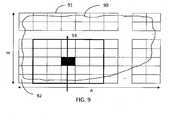
- Fitting a field model to field measurementsmay include firstly defining a grid. This is illustrated in FIG. 8 , where a field 90 is illustrated and a grid 91 overlaying the field 90.
- the gridis an array, for example a regular array, of grid elements 92 with a predetermined resolution, for instance a resolution of 1 meter, of 5 meter, or of 10 meter.
- the resolution of the elements 92 of the grid 91may depend, but does not need to depend, on the working width of the agricultural vehicle system.
- the resolution of the elements 92may correspond, but does not need to correspond, to the working width of the agricultural vehicle system.
- the operator of a combine harvestercommonly uses a working width which is slightly smaller than the width of the grain or corn header.
- the elements 92 in the grid 91are arranged along a first direction x and along a second direction y perpendicular to the first direction.
- the resolution of the elements 92 of the grid 91may be, but does not need to be, the same in both the first direction x and the second direction y.
- the grid 91may comprise e.g. n elements 92 in the first direction x and m elements 92 in the second direction y.
- the elements 92are selected such that a grid 91 at least overlaying the field 90 is obtained.
- the gridmay be rectangular, which is computationally efficient.
- the gridmay for example be hexagonal, or may have any other suitable shape.
- the gridgrows as the agricultural vehicle system moves into new locations. Nevertheless, in advantageous embodiments, the grid may, however, always stay rectangular, meaning that some of the grid elements may fall outside the field.
- the gridmay grow in steps of a predetermined number of elements at a time, e.g. when the driver starts driving along a new column, the grid may grow with m elements, or when the driver starts driving along a new row, the grid may grow with n elements.
- the gridmay be defined by the driver first driving around the field.
- the direction of the gride.g. rectangular grid, at initialization may be assumed to be along the north-south axis. After all, at the start, the main direction of the field may not be known to the system, hence any direction may be selected for the orientation of the grid.
- the selection of the grid 91leads to a matrix F, of which each element is a model value at one point, i.e. in one region 92, of the grid 91.
- the model according to embodiments of the present inventionis a very flexible model: the model can take on any shape because it is not a function, but a collection of model values with predefined relations between all these values.
- the model values of the matrix Fmay be calculated and stored in the location specific memory.
- a value for the field characteristic in front of the agricultural vehicle systemmay be predicted, e.g. calculated, as illustrated by step 191 of FIG. 19 .
- the calculation of the model values (predicted values) in accordance with embodiments of the present inventiontakes the following effects into account:
- the agricultural vehicle systemis controlled at least partly in response to the predicted field value(s) in front thereof, as illustrated by step 192 of FIG. 19 .
- a model matrixis created, containing model values or thus predicted values, the model matrix having the same size as the measurement matrix.
- the model valuesmay be obtained from an optimization problem, wherein a cost function of the model values is optimized, e.g. minimized.
- All these different termsmay be weighted, which is done by the parameters ⁇ t , ⁇ ⁇ ,i , ⁇ ⁇ ,j , ⁇ ⁇ 2 ,i and ⁇ ⁇ 2 ,j .
- the weighing factorsare taken identical for both directions ( i and j ), corresponding to the orthogonal directions x and y as illustrated in FIG. 8 .
- the number of parameters to be tunedmay be reduced to three, namely ⁇ t to weigh the measured values, ⁇ ⁇ to weigh the first order derivative and ⁇ ⁇ 2 to weigh the second order derivative.
- the initial values of the weighting parameterscan be determined based on physical knowledge of the values of these derivatives. These values may then further be improved by tuning (trial and error method around the initial values).
- equation (1)the first and second order derivatives also take into account points surrounding the measurement (or model) matrix.
- equations (4), (5), (6) and (7)the model values near the area to be optimized are also taken into account.
- special precautionsmay be taken to either:
- Equation (6)the second order derivative along the i direction of equation (6) is considered.
- equation (1)For every element of the model matrix, there is a term like equation (6) in equation (1).
- equation (8)the derivative of equation (1) needs to be calculated for each model value. If only the second derivative along the i direction is taken into account, this already leads to three components in the derivative of the model value a i,j . After all, a i,j can be the left, central or right element of equation (6).
- the major computational cost in the modelis solving the system of equations as proposed in equation (8).
- the system sizehas to be limited.
- One solution theretois to only optimize the model values over part of the field 90. In other words, model values in the neighborhood of the current position of the agricultural vehicle system are updated, and the other model values already present are kept as boundary conditions.
- FIG. 1illustrating an embodiment wherein a range of exactly two values around the current position is taken into account.
- ' ⁇ 'indicates the current position of the agricultural vehicle system
- 'x'are locations of which the measurement value is taken into account, if present
- ' ⁇ 'denotes positions of which the model value (if present) is used as boundary conditions for the first and second order derivatives
- ' ⁇ 'denotes positions of which the model value (if present) is only used as boundary conditions for the second order derivative.
- GPS data from an actual field of a little over 1 haare used.
- the field characteristic being the field profileis modeled based on the coordinates and the altitude measurement of a GPS system installed on an agricultural vehicle.
- a similar methodcan be used to model for instance crop conditions such as crop density.
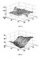
- FIG. 3is a plot of the measured points
- FIG. 4is a corresponding mesh representation.
- the measured fieldclearly has a sink in the middle.
- a gridis defined over the field.
- the gridhas a pre-determined resolution.
- the resolution of the gridis set to 5 meters. With this resolution, the measured field of the example leads to a grid matrix of about 15 by 40 elements.
- a model as expressed by Eq. (1)is used. This model is applied to elements of the grid which lie within a pre-determined span around a current location of the agricultural vehicle system working the field. As an example, for the implementation illustrated a span of 3 values is used. This means that in every time step the model values in an area of 7x7 (2x3+1) 2 elements of the grid are optimized. Experiments have shown that there is little or no benefit in using larger equation spans. This follows from the mathematical description, which defines the field behavior very locally. This local approach is necessary to obtain an accurate description of a heavily non-linear surface as for example shown in FIG. 3 .
- the second order derivative term in the description(cfr. Equation (1)) is actually the most important term for describing the field properties. It makes sure that the profile of the field model is smooth. However, the second order term also may give rise to instability. If there are two values, and one is larger than the other, the second order term will predict a (sometimes steep) slope.
- the first order derivative termguarantees stability. This is illustrated in FIG. 5 and FIG. 6 , in which the model is shown with all the field data incorporated. In FIG. 5 , a very small weight parameter for the first derivative is chosen, in FIG. 6 a 5 times larger first derivative weight is used. The model of FIG. 5 is clearly unstable, while the model of FIG. 6 predicts the field more accurately.
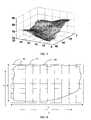
- weighting parameters yielding the best field modelare constant for most field relief, but may depend on the span of the matrix. As mentioned above, for the example illustrated, the surface still appears a bit too sharp.
- the model used for the experimentis not as smooth as it should be in the areas where measurements are present, as the parameters were not optimized. This can be improved by changing the weighting parameters ⁇ t , ⁇ ⁇ ,i , ⁇ ⁇ ,j , ⁇ ⁇ 2 ,i and ⁇ ⁇ 2 ,j of equation (1).
- FIG. 7shows the model with a reduced weight of the measurements. This clearly yields a smoother surface.
- a field 90 to be workedis provided, e.g. overlaid, with a grid 91, e.g. a grid of nxm elements with each a predetermined resolution of e.g. 5 meter by 5 meter, as illustrated in FIG. 8 .
- the elements of the grid 91are filled with values representing a field characteristic.
- the field characteristicmay for example be farmland slope, but the invention is not limited thereto.
- values for the field characteristicare determined by measurement.
- values representing the field characteristic for surrounding elements within a span around the current location of the agricultural vehicle systemare determined by calculation from the model. This is illustrated in FIG. 9 to FIG. 17 .
- the agricultural vehicle systemis provided with a sensor to measure a value for the field characteristic of the element where it passes.
- the agricultural vehicle systemmay for example be provided with a GPS system for measuring altitude of the agricultural vehicle system.
- FIG. 10illustrates the situation where only three measurements have been made in a region with span 2 around the current location of the agricultural vehicle system, this current location being indicated by the square. Based on these three measurement values, the values for the field characteristic of the remaining elements in the region are calculated, and the result is illustrated in FIG. 11 .
- the model according to embodiments of the present inventionis such that it takes into account that the field characteristic varies in a continuous manner. Hence in the travel direction of the agricultural vehicle system (y-direction), where the three measurements made indicate a decrease of the field characteristics, e.g. a downward slope, the model for calculating the non-measured values in accordance with embodiments of the present invention will predict a continuously decreasing field characteristic as illustrated in FIG. 11 . In the other direction (x-direction), perpendicular to the movement direction, where no measurement values nor earlier predicted values are present, the minimal first derivative will lead to same values of the field characteristics as the values already present in the middle column. The result is illustrated in FIG. 11 .
- FIG. 12illustrates a situation in which, during a previous pass, the measurement value indicated at the top of the region with span 2 around the current location of the agricultural vehicle system has been determined.
- the measurement values as indicated in the remainder of the region illustratedhave been determined.
- the corresponding values in the region with span 2 around the actual position of the agricultural vehicle systemare determined by calculation from the model according to embodiments of the present invention.
- the measurement values as illustrated in FIG. 12indicate that, in movement direction, there is first a decrease in the field characteristic, and then a leveling of the field characteristic.
- FIG. 13illustrates, besides the measured values (in bold) also the values as calculated from the model.
- the model according to embodiments of the present inventionis such that it takes into account that the field characteristic varies in a continuous manner. It can be seen from FIG. 13 that the calculated values, in a direction perpendicular to the movement direction, take the same values as the measured values at corresponding level.
- FIG. 14illustrates a region of which one column of values has been determined before.
- the left hand columnmay be values determined e.g. by calculation during a previous pass of the agricultural vehicle system a few columns aside.
- the middle column of valuesmay be determined by measurement by the agricultural vehicle system passing over the elements in this column.
- FIG. 15illustrates, besides the values already known earlier, also the values determined according to the field model correlating a field characteristic, e.g. farmland condition such as farmland slope, or crop condition such as crop density or moisture, to a specific location in the field.
- the field model according to embodiments of the present inventionis such that it takes into account that the field characteristic varies in a substantially constant manner.
- the field characteristic in front of the agricultural vehicle systemis predicted (calculated) to continue to decrease, but in view of the measured constant high values in the left hand column, the decrease in the middle column is reduced with respect to the decrease behind the agricultural vehicle system (derivatives between neighbouring values in the span are minimized). If not, the change in value of the field characteristic in a direction perpendicular to the direction of movement of the agricultural vehicle system would not be in a substantially constant manner.
- FIG. 16illustrates a region with span 2 in which two columns of values are known, in the embodiment illustrated the left hand and right hand columns of the region.
- the unknown values of the regionare determined, i.e. calculated by fitting the model in accordance with embodiments of the present invention to the grid. Derivatives between neighbouring values in the span are minimized in both directions. The resulting values are illustrated in FIG. 17 .
- FIG. 18shows a configuration of processing system 180 that includes at least one programmable processor 181 coupled to a memory subsystem 182 that includes at least one form of memory, e.g., RAM, ROM, and so forth.
- the processor 181 or processorsmay be a general purpose, or a special purpose processor, and may be for inclusion in a device, e.g., a chip that has other components that perform other functions.
- one or more aspects of the present inventioncan be implemented in digital electronic circuitry, or in computer hardware, firmware, software, or in combinations of them.
- the processing system 180may include a storage subsystem 183 that has at least one disk drive and/or CD-ROM drive and/or DVD drive.
- a display system, a keyboard, and a pointing devicemay be included as part of a user interface subsystem 184 to provide for a user to manually input information, such as for example grid dimensions. Ports for inputting and outputting data also may be included. More elements such as interfaces to various devices, and so forth, may be included, but are not illustrated in FIG. 18 .
- the various elements of the processing system 180may be coupled in various ways, including via a bus subsystem 185 shown in FIG. 18 for simplicity as a single bus, but will be understood to those in the art to include a system of at least one bus.
- the memory of the memory subsystem 182may at some time hold part or all (in either case shown as 186) of a set of instructions that when executed on the processing system 180 implement the steps of the method embodiments described hereinabove.
- a system that includes the instructions to implement aspects of the methods for controlling the agricultural vehicle systemis not prior art, and therefore FIG. 18 is not labelled as prior art.
- the present inventionalso includes a computer program product which provides the functionality of any of the methods according to the present invention when executed on a computing device.
- Such computer program productcan be tangibly embodied in a carrier medium carrying machine-readable code for execution by a programmable processor.
- the present inventionthus relates to a carrier medium carrying a computer program product that, when executed on computing means, provides instructions for executing any of the methods as described above.
- carrier mediumrefers to any medium that participates in providing instructions to a processor for execution.
- Such a mediummay take many forms, including but not limited to, non-volatile media, and transmission media.
- Non volatile mediainclude, for example, optical or magnetic disks, such as a storage device which is part of mass storage.
- Computer readable mediainclude, a CD-ROM, a DVD, a flexible disk or floppy disk, a memory key, a tape, a memory chip or cartridge or any other medium from which a computing device can read.
- Various forms of computer readable mediamay be involved in carrying one or more sequences of one or more instructions to a processor for execution.
- the computer program productcan also be transmitted via a carrier wave in a network, such as a LAN, a WAN or the Internet.
- Transmission mediacan take the form of acoustic or light waves, such as those generated during radio wave and infrared data communications. Transmission media include coaxial cables, copper wire and fibre optics, including the wires that comprise a bus within a computer.
Landscapes
- Life Sciences & Earth Sciences (AREA)
- Environmental Sciences (AREA)
- Engineering & Computer Science (AREA)
- Mechanical Engineering (AREA)
- Soil Sciences (AREA)
- Management, Administration, Business Operations System, And Electronic Commerce (AREA)
- Control Of Position, Course, Altitude, Or Attitude Of Moving Bodies (AREA)
Description
- The present invention relates generally to control of agricultural vehicle systems. In particular, the present invention relates to methods and devices for, based on location coordinates and field characteristics collected from an already worked area during a previous pass, predicting which working conditions the agricultural vehicle system will encounter while working a next pass in the field.
- In recent years control systems have been used to alleviate the task of operators of agricultural vehicle systems. Automation allows an operator to concentrate on other tasks such as coordinating transport. Moreover, such control systems guarantee constant performance throughout the day whereas an operator gets tired.
- Control systems on agricultural vehicle systems can only take into account information collected by the agricultural vehicle system at a timet in the past. However, an experienced operator looks ahead and estimates from a previous pass what the machine behavior at a next location might be. A good control system should also anticipate on e.g. the crop condition, just like an experienced operator would. The operator may make a visual assessment of the condition in terms of, for example and amongst others, crop density in front of the machine and/or farmland slope, and acts upon it.
- At present, automatic control systems do not have this upfront information, which makes it hard to have an automated system that is as efficient as an experienced operator. A lot of research has been performed into sensors to measure the harvest condition in front of the machine.
US5995895 describes a control system in which a predetermined geo-referencing map is stored in a memory circuit, the geo-referencing map including site-specific spatially-variable map data indicative of anticipated conditions along the course of travel which may affect the engine load. The control system calculates the anticipated condition using at least actual location signals and the stored map data, and generates a control signal based at least upon the anticipated condition. It is a disadvantage of this system that the geo-referencing data has to be available, either from a previous pass with the same vehicle over the field (geo-referencing data stored when vehicle passed over the field during a previous season for example), or from a pass with another vehicle over the same field (in which case the geo-referencing data needs to be transferred from one vehicle to another).DE19528663 describes a method for controlling an agricultural vehicle system, which is provided with at least one measurement device for determining its position, and at least one further measurement device for determining a control value for controlling the operation of the agricultural vehicle system. The method controls the action of the vehicle system itself, e.g. its speed, by taking into account at least one predicted process variable and/or area feature, wherein during the calculation of the at least one predicted value, use is made of at least one previously recorded measurement at a particular location. For the prediction of the process variable and/or area feature at a location X, all measurement values of this process variable and/or area feature already obtained before within a range with predetermined radius around location X are taken into account. Different possibilities are set out. In one embodiment, the predicted value may be a mean value of the already measured values within the range. In another embodiment, a weighted value of already measured values within the range may be built whereby different weights are assigned to different measured values depending on their distance from location X within the pre-determined range, taking into account the direction of the change of the measurement values. In yet another embodiment, the prediction may be done solely on the basis of a measurement value of a location adjacent the location of which the prediction is to be made. It is a disadvantage of the model used inDE19528663 that predictions are not accurate enough.US6490539 describes an automatic vision guidance system for an agricultural vehicle is disclosed and described. The vision guidance system uses a K-means clustering algorithm in image processing to distinguish between crop and non-crop features. The vision guidance system utilizes moment algorithms to determine the location and orientation of crop rows, from which desired wheel angles are determined and steering is commanded. The vision guidance system may adjust the location and orientation of visually determined crop rows according to a predetermined distance between crop rows. Further, the vision guidance system may utilize a redundant number of regions of interest in determining crop row locations and orientations.- There is room for improved control systems for agricultural vehicle systems.
- It is an object of embodiments of the present invention to provide a good method and device for controlling an agricultural vehicle system.
- The above objective is accomplished by a method and device according to claims 1 and 9.
- Particular and preferred aspects of the invention are set out in the accompanying dependent claims.
- In a first aspect, the present invention provides a method for controlling an agricultural vehicle system when moving along a course of travel over a field. The method comprises:
- providing a field model correlating a field characteristic, e.g. a farmland condition such as farmland slope, or a crop condition such as crop density or moisture, to a specific location in the field, for example indicated by x andy coordinates,
- from the field model and at least one previously obtained value for the field characteristic, predicting a value for the field characteristic in front of the agricultural vehicle system thus obtaining an anticipated field characteristic, and
- controlling the agricultural vehicle system at least partly in response to the anticipated field characteristic.
- In accordance with the present invention, providing a field model correlating a field characteristic to a specific location in the field includes assuming that the field characteristic varies in a continuous manner.
- It is an advantage of a method according to the present invention that a better field model and better predictions are obtained by removing effects of noise and/or disturbances. Furthermore, it is advantageous that a method according to embodiments of the present invention yields good results without it being necessary to have data from a previous pass of this or another agricultural vehicle system available.
- The method according to the present invention comprises field model variables, assuming that the field characteristic varies in a continuous manner may comprise taking into account first and second order derivatives of the field model variables. This way, it is possible to model that in nature the curve of any object varies as little as possible and that in nature curves also vary smoothly. In the present invention, providing a field model describing a field characteristic comprises optimizing a cost function that takes account of the difference between a model value and a measured value at a specific location, of the first derivatives in orthogonal directions of the model values and of the second derivatives in orthogonal directions of the model values. Advantageously, the method of providing the field model may comprise summing a factor related to the squared difference between a model value and a measured value at an element, a factor related to the squared first derivative in orthogonal directions of the model values and a factor related to the squared second derivatives in orthogonal directions of the model values. Providing a field model may comprise weighting the factors before summing. This allows to smooth the result. Weighting the factors before summing may be performed by introducing weighting parameters. Suitable weighting parameters may be determined by trial and error.
- In accordance with embodiments of the present invention, predicting a value for the field characteristic in front of the agricultural vehicle system may comprise calculating field characteristic values in a region around a current location of the agricultural vehicle system determined by a span not larger than 6 , for example a span not larger than 3. The span is related to computation time; a limited span means a faster calculation and less calculation power needed, and hence allows to perform the calculation on-line. This is advantageous as an agricultural vehicle system can do measurements and on-line calculations in a field it never visited before, and still anticipate very well on potential changes in field characteristic.
- In a method according to embodiments of the present invention, predicting a value for the field characteristic in front of the agricultural vehicle system may comprise updating the model of the field as new measurements become available. This way, the model values, i.e. predicted values, will become more and more accurate, and hence the behavior of the agricultural vehicle system based on these predicted values will be better.
- A method according to embodiments of the present invention may furthermore comprise fitting a grid over the field, the grid consisting of a plurality of elements, and determining a value for the field characteristic of the elements of the grid. This way, continuous measurements and calculations in the continuous domain may be converted into discrete measurements and calculations in the discrete domain, thus reducing the required calculation power. In particular embodiments of the present invention, fitting a grid over the field may comprise fitting a grid over the field with a resolution determined by the working width of an appliance of the agricultural vehicle system. In such embodiments, the resolution may for example be substantially equal to the width of the appliance, or may be an integer multiple of the width of the appliance, or the width of the appliance may be an integer multiple of the resolution. In alternative embodiments, the grid fit over the field may have a resolution which is not related to the width of an appliance of the agricultural vehicle system. In the case of a combine harvester this appliance may comprise a header, such as a grain or corn header, which cuts the crop from the field and supplies it centrally to a feeder mechanism of the harvester.
- In a second aspect, the present invention provides a computer program product for executing any of the methods of embodiments of the first aspect of the present invention when executed on a computing device associated with an agricultural vehicle device. Accordingly, the present invention includes a computer program product which provides the functionality of any of the methods according to the first aspect of the present invention when executed on a computing device associated with an agricultural vehicle device.
- The present invention also provides a machine readable data storage (data carrier) such as a CD-ROM, a memory key or a diskette which stores the computer product in a machine readable form and which executes at least one of the methods of the invention when executed on a computing device. Nowadays, such software is often offered on the Internet or a company Intranet for download, hence the present invention includes transmitting the agricultural vehicle system computer product according to embodiments of the present invention over a local or wide area telecommunications network. The computing device may include one of a microprocessor and an FPGA.
- One embodiment is a method for controlling an agricultural vehicle system, implemented as a computer program that runs on a computer processing system. The computer program may be part of a computer software product (i.e. a carrier medium) that includes one or more code segments that cause a processor such as a CPU of the processing system to carry out the steps of the method. The program runs under an operating system, and may include a user interface that enables a user to interact with the program. The control program operates on input data and generates predicted field characteristic values for controlling the agricultural vehicle system.
- In a further aspect, the present invention provides an agricultural vehicle system adapted for being controlled by a control signal generated based on a predicted value for a field characteristic in front of the agricultural vehicle system, the predicted value being calculated from a field model correlating the field characteristic to a specific location in the field and at least one previously obtained value for the field characteristic, wherein the field model assumes that the field characteristic varies in a continuous manner in accordance with claim 9. It is an advantage of an agricultural vehicle system according to embodiments of the present invention that, although the agricultural vehicle system does not need to rely on sensors being mounted to scan field characteristics ahead of the agricultural vehicle system when in use, that it nevertheless provides good means for controlling the agricultural vehicle system with respect to the predicted values for the field characteristic. It is an advantage of the agricultural vehicle system according to embodiments of the present invention that it guarantees constant performance throughout the field and over time.
- An agricultural vehicle system according to embodiments of the present invention may furthermore comprise a control system for controlling a vehicle system driving parameter, such as e.g. vehicle or engine speed or transmission ratio, or a vehicle system attribute parameter, such as e.g. rotor speed, sieve opening size, cleaning fan speed or fertilizer flow. The control system may be adapted for generating the control signal.
- An agricultural vehicle system according to embodiments of the present invention may furthermore comprise a sensor unit for measuring the field characteristic, for example the sensor unit may comprise one or more of a farmland condition sensor, e.g. a farmland slope sensor, or a crop condition sensor, e.g. a crop density or moisture content sensor. Measurement values from the sensor unit may be taken into account when predicting values for a field characteristic for generating the control signal.
- An agricultural vehicle system according to embodiments of the present invention may furthermore comprise a first location specific memory for storing measurement values of one or more field characteristics. An agricultural vehicle system according to embodiments of the present invention may comprise a second location specific memory for storing model values of one or more field characteristics. The first and the second location specific memory may be physically one and the same memory.
- For purposes of summarizing the invention and the advantages achieved over the prior art, certain objects and advantages of the invention have been described herein above. Of course, it is to be understood that not necessarily all such objects or advantages may be achieved in accordance with any particular embodiment of the invention. Thus, for example, those skilled in the art will recognize that the invention may be embodied or carried out in a manner that achieves or optimizes one advantage or group of advantages as taught herein without necessarily achieving other objects or advantages as may be taught or suggested herein.
FIG. 1 illustrates values around a current location of an agricultural vehicle, which values may be taken into account for determining model values in accordance with embodiments of the present invention.FIG. 2 is a graphical representation of the average execution times as presented in Table 2. A steep increase in computation time in function of the problem size is to be noted.FIG. 3 illustrates GPS height measurement of a field.FIG. 4 illustrates a mesh representation of the field of which the GPS height measurements are illustrated inFIG. 3 .FIG. 5 illustrates a first embodiment of a field model of the present invention with a small first derivative term in the objective function, i.e. in the cost function that is optimized.FIG. 6 illustrates a second embodiment of the field model of the present invention with a larger first derivative term compared to the model as illustrated inFIG. 5 . The first derivative term clearly stabilizes the model.FIG. 7 illustrates a third embodiment of the field model of the present invention with a reduced weight for the measurements, which leads to a smoother model.FIG. 8 illustrates an exemplary field to be worked, overlaid with a grid of nxm elements.FIG. 9 illustrates the field to be worked as illustrated inFIG. 8 , wherein a region with a pre-determined span around a current location of an agricultural vehicle is illustrated, which region is used for calculating field characteristic values of the elements within the region with the pre-determined span.FIG. 10 ,FIG. 12 ,FIG. 14 andFIG. 16 illustrate one region of the grid, in which previously determined values, e.g. measurement values or calculated values, are available; andFIG. 11 ,FIG. 13 ,FIG. 15 andFIG. 17 respectively illustrate on top thereof model values as determined by means of a model in accordance with embodiments of the present invention.FIG. 18 schematically illustrates a processing system including at least one programmable processor which may be programmed so as to perform a method according to embodiments of the present invention.FIG. 19 is a flow diagram schematically illustrating the basics behind a method according to embodiments of the present invention.- The drawings are only schematic and are non-limiting. In the drawings, the size of some of the elements may be exaggerated and not drawn on scale for illustrative purposes.
- In the different drawings, the same reference signs refer to the same or analogous elements.
- The present invention is for use with agricultural vehicle systems. Agricultural vehicle systems are motorized vehicles designed for performing a particular agricultural task, e.g. harvesting machinery such as combine or forage harvesters, plows or fertilizer spreaders. Agricultural vehicle systems in embodiments of the present invention include any agricultural vehicle that performs site-specific measurements relating to field characteristics, e.g. farmland conditions such as topography, farmland slope, soil moisture, soil type, or crop conditions, such as crop density, toughness of the crop, moisture content, crop height. The field characteristics in accordance with embodiments of the present invention are characteristics of the environment, external to the agricultural vehicle system, but which nevertheless affect the performance of the agricultural vehicle system.
- Examples of relevant field characteristics are given below, the list not being exhaustive:
- Farmland slope: It has been shown that, at least for some agricultural vehicle systems, agricultural vehicle capacity, e.g. the effective combine capacity, decreases uphill, because the cleaning losses increase. If the slope information is available, the agricultural vehicle system, e.g. combine, can slow down before the losses actually increase. If the agricultural vehicle system delays the slowing down till the losses are actually measured to increase, it always responds too late. Because of the delay for crop processing and cleaning it takes quite some time before the losses return to their normal levels.
- Crop density: The crop density may vary throughout the field because of environmental parameters such as e.g. varying sunlight conditions, different soil types and varying fertilizer distribution. If the crop density in front of the machine is known, the controller can anticipate on crop density variations just like an operator would based on his upfront view of the field.
- Moisture content: The moisture content of the crop has significant impact on the threshing and cleaning process. Normally the moisture content is measured in the grain elevator, after the cleaning process. This means that it is impossible to adjust the threshing and cleaning system on time. By predicting the moisture content based on earlier measurements, it is possible to timely adjust the machine settings.
- These are just a few examples of biological and farmland variables that can be predicted based on earlier measurements.
- An agricultural vehicle system according to embodiments of the present invention is provided with a control system for controlling the operation thereof. Controlling the operation of the agricultural vehicle system may include controlling a vehicle system driving parameter such as vehicle travel speed, through the control of the engine speed or transmission ratio, or controlling a vehicle system attribute parameter, such as processing rotor speed, sieve opening size, cleaning fan speed, fertilizer flow.
- To make sure that e.g. crop processors receive sufficient power from a relatively fixed power budget of an agricultural vehicle system to efficiently process crop with acceptable loss rates, it may be desirable to control vehicle speed as a function of the power demand or of the load of the crop processors. Thus, vehicle speed is preferably reduced as a vehicle enters areas of a field with dense crop conditions and is increased as the vehicle enters areas with sparse crop conditions. Maximum efficiency is achieved by setting vehicle speed as high as possible while maintaining acceptable loss rates or threshing performance. Preferably the controller anticipates on the field characteristics, and hence anticipates by decreasing or increasing the vehicle speed.
- In order to obtain this anticipation, embodiments of the present invention focus on adding a location specific memory to a control system of an agricultural vehicle system in accordance with embodiments of the present invention. Measurement values of one or more field characteristics are stored in the location specific memory. Hereto, the agricultural vehicle system or the control system thereof is provided with a location sensor, e.g. a GPS device. Based on the sensed locations, the corresponding measurement values of the one or more field characteristics are stored in the location specific memory.
- In this way the results of measurements of field characteristics, such as crop conditions, e.g. crop density, and/or farmland conditions, e.g. slope, performed by an agricultural vehicle system on one location can be used to predict the field characteristics on a neighboring location. Based on these earlier measurements the field characteristic in front of the combine harvester may be predicted.
- Location information such as GPS location measurements, including latitude and longitude measurements, and GPS altitude measurements may be used. Based on these location measurements, in accordance with embodiments of the present invention, it is possible to predict field characteristics, e.g. the slope of the farmland. It is to be noted that the accuracy of any GPS system is much lower in the vertical direction than in the horizontal direction. The performance of the model may be improved by including the inclination measurements, on the agricultural vehicle system, e.g. from a longitudinally arranged sensor, and/or by including differential correction.
- A flow chart of a method according to embodiments of the present invention is illustrated in
FIG. 19 . - In accordance with embodiments of the present invention, in order to be able to obtain the predictions, a field model is provided, as illustrated in
step 190 ofFIG. 19 . The field model correlates a field characteristic, e.g. farmland condition such as farmland slope, or crop condition such as crop density or moisture, to a specific location in the field. The field model is a mathematical expression of the behavior, e.g. variation, of at least one field characteristic over the field. The purpose of this field model is to predict field characteristics such as crop condition and/or farmland condition, e.g. characteristics of the crop (biological) and the farmland (topographic). The field characteristics, which may for example represent harvest properties, may be predicted at least for locations in front of the agricultural vehicle system, based on earlier measurements near the current location and/or based on earlier predicted field characteristic values near the current location. The predicted field characteristics in front of the agricultural vehicle system may be used to anticipate in the control of the agricultural vehicle system, e.g. of the vehicle speed or of crop processing settings such as rotor speed, sieve openings, cleaning fan speed, etc. - The field model according to embodiments of the present invention is assumed to always show the following characteristics:
- The measurement values of the field characteristics are not exact, but are corrupted by noise, including sensor noise and/or process noise.
- On locations where no measurements are performed the field characteristics to be predicted are linked to the field, and not to the state of the agricultural vehicle system. In other words, if a variable has a certain value at location A, it will have a similar value at all locations B which are in the vicinity of location A, independent of the state of the agricultural vehicle system.
- The field characteristics vary in a continuous manner; no sudden changes of the field characteristics are possible.
- The field characteristic is a measurement of some biological or topographic quantity, which implies that one can assume a smooth first derivative, implying a minimal second derivative.
- On the agricultural vehicle system a location sensor providing position information, e.g. GPS position information, is available such that the measurements of the field characteristics can be related to an actual location in the field. The above assumptions aid in selecting a suitable model structure.
- An approach taken in accordance with embodiments of the present invention is to fit a model to the field measurements, and to update this model online. Since the shape of a field characteristic, e.g. a biological variable, across a field may be very blurred, it is advantageous to use a numerical model rather than an analytical model.
- Fitting a field model to field measurements may include firstly defining a grid. This is illustrated in
FIG. 8 , where afield 90 is illustrated and agrid 91 overlaying thefield 90. The grid is an array, for example a regular array, ofgrid elements 92 with a predetermined resolution, for instance a resolution of 1 meter, of 5 meter, or of 10 meter. The resolution of theelements 92 of thegrid 91 may depend, but does not need to depend, on the working width of the agricultural vehicle system. The resolution of theelements 92 may correspond, but does not need to correspond, to the working width of the agricultural vehicle system. For example, the operator of a combine harvester commonly uses a working width which is slightly smaller than the width of the grain or corn header. Theelements 92 in thegrid 91 are arranged along a first direction x and along a second directiony perpendicular to the first direction. The resolution of theelements 92 of thegrid 91 may be, but does not need to be, the same in both the first directionx and the second direction y. Thegrid 91 may comprise e.g. nelements 92 in the first directionx and melements 92 in the second direction y. Theelements 92 are selected such that agrid 91 at least overlaying thefield 90 is obtained. In particular embodiments, the grid may be rectangular, which is computationally efficient. In alternative embodiments, the grid may for example be hexagonal, or may have any other suitable shape. - In embodiments of the present invention, the grid grows as the agricultural vehicle system moves into new locations. Nevertheless, in advantageous embodiments, the grid may, however, always stay rectangular, meaning that some of the grid elements may fall outside the field. To minimize computational overhead, the grid may grow in steps of a predetermined number of elements at a time, e.g. when the driver starts driving along a new column, the grid may grow with m elements, or when the driver starts driving along a new row, the grid may grow with n elements.
- In a particular implementation, the grid may be defined by the driver first driving around the field.
- The direction of the grid, e.g. rectangular grid, at initialization may be assumed to be along the north-south axis. After all, at the start, the main direction of the field may not be known to the system, hence any direction may be selected for the orientation of the grid.
- The selection of the
grid 91 leads to a matrixF, of which each element is a model value at one point, i.e. in oneregion 92, of thegrid 91. The model according to embodiments of the present invention is a very flexible model: the model can take on any shape because it is not a function, but a collection of model values with predefined relations between all these values. - In a next step, the model values of the matrixF may be calculated and stored in the location specific memory. In particular, from the field model and at least one previously obtained model value, a value for the field characteristic in front of the agricultural vehicle system may be predicted, e.g. calculated, as illustrated by
step 191 ofFIG. 19 . The calculation of the model values (predicted values) in accordance with embodiments of the present invention takes the following effects into account: - Measurements: Measurements which have already been made, pull model values in the direction of the measured values. Each actual measurement is attributed to one position on the grid 91 (and thus in the matrixF). Nevertheless, the field measurements are not exact and are corrupted by noise such as sensor noise and/or process noise. If the field measurements would be exact, the model would pass through all the measurements. A model according to embodiments of the present invention does not do that. There may remain a considerable difference between a model value and a corresponding field measurement.
- Minimal first derivative: In nature the curve of any object varies as little as possible. Things tend to level out. This also applies to field characteristics such as crop conditions, e.g. crop density, and farmland conditions, e.g. terrain slope. During the modeling phase the derivative between two neighboring model values is penalized. In other words, the model surface can only deviate from a plane if measurements pull sufficiently hard.
- Minimal second derivative: In nature curves also vary smoothly. So, the first derivative should not change unless it is strictly necessary. Hence, in particular embodiments, also the second derivative between two neighbouring model values may be minimized. In alternative embodiments, more than two neighbouring model values may be taken into account for minimizing the second derivative.
- Each of the above-mentioned effects has its importance, but of course, the effects need to be balanced with each other, which is a tuning exercise.
- During use, the agricultural vehicle system is controlled at least partly in response to the predicted field value(s) in front thereof, as illustrated by
step 192 ofFIG. 19 . - The above-presented approach is formalized in a mathematical description. First of all any measured values are discretized into a measurement matrix. Such transformation from geographically continuous measurement values to matrix elements may comprise the following steps:
- 1. Express GPS coordinates (latitude, longitude) in meters, e.g. by conversion of the GPS coordinates into the WGS84 Geodetic Coordinate system. In this way the position of the agricultural vehicle system may for example be expressed in meters with respect to the starting position of the agricultural vehicle system.
- 2. As the main direction of the field is not known in advance, in accordance with embodiments of the present invention, the matrix dimensions may be aligned with the North-South and East-West axis of the globe. In accordance with alternative embodiments, for example if an indication of the orientation of the field would be known in advance, any other suitable orientation may be taken as the main direction. The values of the x- and y-components of the first measurement in the field may be stored, for example as offsetx and offsety. This only happens when the first measurement value is added. At this time the offset is defined, such that all the measurements are relative to the first position in the field, as indicated under point 1 above.
- 3. The continuous coordinates are then transformed into discrete coordinates. The resolution of the measurement matrix may be set to a pre-determined resolution value. As an example, the resolution of the measurement matrix may be set to 5 meters. Of course the selection of the resolution of the measurement matrix is a trade-off between computation time and accuracy. However, most agricultural vehicle systems, such as e.g. combine harvesters, will normally not come closer than 5 meters to each other since most headers are wider than 5 meters. If several measurements relate to a same matrix element, an average measurement for that matrix element may be determined.
- 4. In embodiments of the present invention, the measurement matrix may be automatically enlarged when measurements outside the current measurement matrix are encountered.
- Besides the measurement matrix, a model matrix is created, containing model values or thus predicted values, the model matrix having the same size as the measurement matrix. The model values may be obtained from an optimization problem, wherein a cost function of the model values is optimized, e.g. minimized.
- In particular embodiments, as an example only, the cost function to be optimized sums, for each location in the grid, the weighted squared difference between the model value and a measured value at that location, the weighted squared first derivative in orthogonal directions of the model values and the weighted squared second derivatives in orthogonal directions of the model values:

with
whereai,j is the model value, or thus the predicted value, at position(i, j),ti,j the measured value at the same position andci,j indicates if a measurement is available at the position(i, j). All these different terms may be weighted, which is done by the parametersβt, βδ,i, βδ,j, βδ2 ,i andβδ2 ,j. Normally the weighing factors are taken identical for both directions (i andj), corresponding to the orthogonal directionsx andy as illustrated inFIG. 8 . Thus the number of parameters to be tuned may be reduced to three, namelyβt to weigh the measured values,βδ to weigh the first order derivative andβδ2 to weigh the second order derivative. The initial values of the weighting parameters can be determined based on physical knowledge of the values of these derivatives. These values may then further be improved by tuning (trial and error method around the initial values). - Since the number of target value terms varies, depending on the environment of the agricultural vehicle system, all terms may first be normalized with γt, γδ and γδ
2 , and then weighted with their respective factors. One could add an additional requirement to these weighting parameters without loss of generality, namely:
which reduces the number of independent parameters to be tuned to two. The first derivatives of equation (1) may be defined as:

- The second order derivatives may be defined as:


- It is to be noted that in equation (1) the first and second order derivatives also take into account points surrounding the measurement (or model) matrix. In general, from the equations defining the first and second order derivatives, i.e. equations (4), (5), (6) and (7), follows that the model values near the area to be optimized are also taken into account.
- In particular embodiments, special precautions may be taken to either:
- use the model values outside the current measurement matrix, being a subset of the measurement matrix defined by the model span for example as illustrated in
FIG. 1 ; - or, to modify the functions as defined by equation (1) such that the derivatives only take values inside the measurement matrix into account. This is the default situation if no model values outside the measurement matrix are known.
- The above and other border conditions may be taken into account, and a plurality of possible implementations exist.
- Optimizing, e.g. minimizing, the cost function shown in equation (1) comes down to solving the following system of equations:

- In other words, for each model value, a linear equation is added to the system.
- As an example the second order derivative along the i direction of equation (6) is considered. The following notational convention may be used:

whereal stands for the left element,ac the central element andar the right element. For every element of the model matrix, there is a term like equation (6) in equation (1). As shown in equation (8), the derivative of equation (1) needs to be calculated for each model value. If only the second derivative along the i direction is taken into account, this already leads to three components in the derivative of the model valueai,j. After all,ai,j can be the left, central or right element of equation (6). - First of all, the derivatives of equation (6) toal, ac andar are to be calculated; this yields, except for a constant factor which does not influence the result:

- Now, the contribution of the second derivative in the i-direction as given in equation (6), to the derivative of equation (1) toai,j is calculated, withai,j a model value in the middle of the model matrix (no boundary effects). This can be summarized in Table 1. The effect of the other terms of equation (1) is calculated analogously, but not illustrated below.
Table 1: The contribution of equation (6) to the derivative of equation (1) toai,j. ak-2,l ak-1,l ak,l ak+1,l ak+2,l al 0.5 -1 0.5 ac -1 2 -1 ar 0.5 -1 0.5 TOTAL 0.5 -2 3 -2 0.5 The contributions ofal, ac andar in equation (10) are listed separately. - It is an advantage of a model in accordance with embodiments of the present invention that it has the capability to make a smooth extrapolation of the field towards unvisited areas. Of course, the extrapolation values are only a best guess since there are no actual measurements, but they give an idea what to expect in that area. This may be very useful to optimize the operation of an agricultural vehicle system such as for example a combine harvester.
- Online application of a method according to embodiments of the present invention adds two extra requirements to the method as set out above, namely:
- The computational complexity has to be acceptable. Online application requires the algorithm to run at regular time intervals, for instance once every 10 seconds. Thus it has to be feasible to perform the complete calculation within that time frame on hardware available on the agricultural vehicle system.
- A system of updates has to be devised, to allow adding new information (measurement values) to the existing model. As new measurements become available, the model of the field is updated recursively.
- The major computational cost in the model is solving the system of equations as proposed in equation (8). In order to be able to perform the model update online within the pre-determined, limited time interval, the system size has to be limited. One solution thereto is to only optimize the model values over part of the
field 90. In other words, model values in the neighborhood of the current position of the agricultural vehicle system are updated, and the other model values already present are kept as boundary conditions. - For the second order derivative to work correctly, values for a span of at least two elements in all directions around the current position need to be taken into account. This is illustrated in
FIG. 1 , illustrating an embodiment wherein a range of exactly two values around the current position is taken into account. InFIG. 1 , '◊' indicates the current position of the agricultural vehicle system, 'x' are locations of which the measurement value is taken into account, if present, '■' denotes positions of which the model value (if present) is used as boundary conditions for the first and second order derivatives, and '□' denotes positions of which the model value (if present) is only used as boundary conditions for the second order derivative. - To have an idea of the feasibility of a model according to embodiments of the present invention in an online environment, the execution times are recorded for different ranges of the local model. These tests were performed in Matlab on a Windows XP machine (Intel 2.0Gz, 1 GB RAM). It is to be noted that no efforts were made to optimize the implementation of the algorithm. The results are shown in Table 2.
Table 2: Computation time required for one update step of the algorithm for different model spans. A model span 2 means that two measurement values in every direction around the combine position are taken into account.Model span Time (s) Mean Std Median Min Max 2 0.0108 0.0073 0.0150 0 0.0150 3 0.0230 0.0078 0.0160 0.0150 0.0320 4 0.0502 0.0068 0.0470 0.0460 0.0780 5 0.1253 0.0078 0.1250 0.1090 0.1410 6 0.2816 0.0135 0.2810 0.2500 0.3130 7 0.7439 0.0315 0.7500 0.6560 0.8130 - It is to be noted that the execution time is recorded with Matlab, which implies that very low times are not accurately measured. This is probably the reason why the standard deviation remains substantially constant for the first few model spans. The computation time is acceptable, but increases rapidly with model span increase. The average execution time doubles for each increment (with 1) of the model span. This can be expected, since the problem size (number of variables) increases quadratically with the model span, and the solution time of a system of equations is known to be O(x3) with x the number of variables. The average execution times are plotted in
FIG. 2 . The steep increase in computation time in function of the problem size is to be noted. - Tests have shown that a model span of 3 already yields quite good results (with a position resolution of 5 meter). Of course, if the resolution is increased, a larger model span will be needed to reach the same model characteristics.
- To illustrate the method according to embodiments of the present invention, GPS data from an actual field of a little over 1 ha are used. In the embodiment illustrated, the field characteristic being the field profile is modeled based on the coordinates and the altitude measurement of a GPS system installed on an agricultural vehicle. Of course, in accordance with embodiments of the present invention, a similar method can be used to model for instance crop conditions such as crop density.
- The measured altitudes of the field used in the example are shown in
FIG. 3 and FIG. 4. FIG. 3 is a plot of the measured points, andFIG. 4 is a corresponding mesh representation. The measured field clearly has a sink in the middle. - In accordance with embodiments of the present invention, a grid is defined over the field. The grid has a pre-determined resolution. In the embodiment illustrated, the resolution of the grid is set to 5 meters. With this resolution, the measured field of the example leads to a grid matrix of about 15 by 40 elements.
- A model as expressed by Eq. (1) is used. This model is applied to elements of the grid which lie within a pre-determined span around a current location of the agricultural vehicle system working the field. As an example, for the implementation illustrated a span of 3 values is used. This means that in every time step the model values in an area of 7x7 (2x3+1)2 elements of the grid are optimized. Experiments have shown that there is little or no benefit in using larger equation spans. This follows from the mathematical description, which defines the field behavior very locally. This local approach is necessary to obtain an accurate description of a heavily non-linear surface as for example shown in
FIG. 3 . - The second order derivative term in the description (cfr. Equation (1)) is actually the most important term for describing the field properties. It makes sure that the profile of the field model is smooth. However, the second order term also may give rise to instability. If there are two values, and one is larger than the other, the second order term will predict a (sometimes steep) slope. The first order derivative term guarantees stability. This is illustrated in
FIG. 5 and FIG. 6 , in which the model is shown with all the field data incorporated. InFIG. 5 , a very small weight parameter for the first derivative is chosen, inFIG. 6 a 5 times larger first derivative weight is used. The model ofFIG. 5 is clearly unstable, while the model ofFIG. 6 predicts the field more accurately. - Of course, another useful component is the relative weight of the measurements themselves (first term in Equation (1)). The weighting parameters yielding the best field model are constant for most field relief, but may depend on the span of the matrix. As mentioned above, for the example illustrated, the surface still appears a bit too sharp. The model used for the experiment is not as smooth as it should be in the areas where measurements are present, as the parameters were not optimized. This can be improved by changing the weighting parametersβt, βδ,i, βδ,j,βδ
2 ,i andβδ2 ,j of equation (1). The effect of tuning the weighting parameters is illustrated inFIG. 7 , which shows the model with a reduced weight of the measurements. This clearly yields a smoother surface. - In the following, a few schematic examples are illustrated of how a model in accordance with embodiments of the present invention may be applied to a grid overlaying a field.
- As an example, a
field 90 to be worked is provided, e.g. overlaid, with agrid 91, e.g. a grid of nxm elements with each a predetermined resolution of e.g. 5 meter by 5 meter, as illustrated inFIG. 8 . Over time, during a time period during which an agricultural vehicle system works the field, the elements of thegrid 91, in accordance with embodiments of the present invention, are filled with values representing a field characteristic. The field characteristic may for example be farmland slope, but the invention is not limited thereto. In accordance with embodiments of the present invention, when an agricultural vehicle system passes over the elements, values for the field characteristic are determined by measurement. At the same time, values representing the field characteristic for surrounding elements within a span around the current location of the agricultural vehicle system are determined by calculation from the model. This is illustrated inFIG. 9 to FIG. 17 . - When an agricultural vehicle system starts a
first pass 93 through the field 90 (FIG. 9 ), none of the elements has been accorded a value for the field characteristic yet. The agricultural vehicle system is provided with a sensor to measure a value for the field characteristic of the element where it passes. In the example illustrated, the agricultural vehicle system may for example be provided with a GPS system for measuring altitude of the agricultural vehicle system. FIG. 10 illustrates the situation where only three measurements have been made in a region withspan 2 around the current location of the agricultural vehicle system, this current location being indicated by the square. Based on these three measurement values, the values for the field characteristic of the remaining elements in the region are calculated, and the result is illustrated inFIG. 11 . The model according to embodiments of the present invention is such that it takes into account that the field characteristic varies in a continuous manner. Hence in the travel direction of the agricultural vehicle system (y-direction), where the three measurements made indicate a decrease of the field characteristics, e.g. a downward slope, the model for calculating the non-measured values in accordance with embodiments of the present invention will predict a continuously decreasing field characteristic as illustrated inFIG. 11 . In the other direction (x-direction), perpendicular to the movement direction, where no measurement values nor earlier predicted values are present, the minimal first derivative will lead to same values of the field characteristics as the values already present in the middle column. The result is illustrated inFIG. 11 .FIG. 12 illustrates a situation in which, during a previous pass, the measurement value indicated at the top of the region withspan 2 around the current location of the agricultural vehicle system has been determined. During the current pass, when the agricultural vehicle system drives through the field, measurement values as indicated in the remainder of the region illustrated have been determined. The corresponding values in the region withspan 2 around the actual position of the agricultural vehicle system (indicated by the square) are determined by calculation from the model according to embodiments of the present invention. The measurement values as illustrated inFIG. 12 indicate that, in movement direction, there is first a decrease in the field characteristic, and then a leveling of the field characteristic.FIG. 13 illustrates, besides the measured values (in bold) also the values as calculated from the model. The model according to embodiments of the present invention is such that it takes into account that the field characteristic varies in a continuous manner. It can be seen fromFIG. 13 that the calculated values, in a direction perpendicular to the movement direction, take the same values as the measured values at corresponding level.FIG. 14 illustrates a region of which one column of values has been determined before. As an example only, the left hand column may be values determined e.g. by calculation during a previous pass of the agricultural vehicle system a few columns aside. The middle column of values may be determined by measurement by the agricultural vehicle system passing over the elements in this column.FIG. 15 illustrates, besides the values already known earlier, also the values determined according to the field model correlating a field characteristic, e.g. farmland condition such as farmland slope, or crop condition such as crop density or moisture, to a specific location in the field. The field model according to embodiments of the present invention is such that it takes into account that the field characteristic varies in a substantially constant manner. The field characteristic in front of the agricultural vehicle system is predicted (calculated) to continue to decrease, but in view of the measured constant high values in the left hand column, the decrease in the middle column is reduced with respect to the decrease behind the agricultural vehicle system (derivatives between neighbouring values in the span are minimized). If not, the change in value of the field characteristic in a direction perpendicular to the direction of movement of the agricultural vehicle system would not be in a substantially constant manner.FIG. 16 illustrates a region withspan 2 in which two columns of values are known, in the embodiment illustrated the left hand and right hand columns of the region. When an agricultural vehicle system passes over the middle column of the region, and is present in the centre of the region, as indicated by the square, the unknown values of the region are determined, i.e. calculated by fitting the model in accordance with embodiments of the present invention to the grid. Derivatives between neighbouring values in the span are minimized in both directions. The resulting values are illustrated inFIG. 17 .- The above-described method embodiments of the present invention may be implemented in a processing system such as illustrated in
FIG. 18 , which shows a configuration ofprocessing system 180 that includes at least oneprogrammable processor 181 coupled to a memory subsystem 182 that includes at least one form of memory, e.g., RAM, ROM, and so forth. It is to be noted that theprocessor 181 or processors may be a general purpose, or a special purpose processor, and may be for inclusion in a device, e.g., a chip that has other components that perform other functions. Thus, one or more aspects of the present invention can be implemented in digital electronic circuitry, or in computer hardware, firmware, software, or in combinations of them. Theprocessing system 180 may include astorage subsystem 183 that has at least one disk drive and/or CD-ROM drive and/or DVD drive. In some implementations, a display system, a keyboard, and a pointing device may be included as part of auser interface subsystem 184 to provide for a user to manually input information, such as for example grid dimensions. Ports for inputting and outputting data also may be included. More elements such as interfaces to various devices, and so forth, may be included, but are not illustrated inFIG. 18 . The various elements of theprocessing system 180 may be coupled in various ways, including via abus subsystem 185 shown inFIG. 18 for simplicity as a single bus, but will be understood to those in the art to include a system of at least one bus. The memory of the memory subsystem 182 may at some time hold part or all (in either case shown as 186) of a set of instructions that when executed on theprocessing system 180 implement the steps of the method embodiments described hereinabove. Thus, while the hardware of aprocessing system 180 such as shown inFIG. 18 is prior art, a system that includes the instructions to implement aspects of the methods for controlling the agricultural vehicle system is not prior art, and thereforeFIG. 18 is not labelled as prior art. - The present invention also includes a computer program product which provides the functionality of any of the methods according to the present invention when executed on a computing device. Such computer program product can be tangibly embodied in a carrier medium carrying machine-readable code for execution by a programmable processor. The present invention thus relates to a carrier medium carrying a computer program product that, when executed on computing means, provides instructions for executing any of the methods as described above. The term "carrier medium" refers to any medium that participates in providing instructions to a processor for execution. Such a medium may take many forms, including but not limited to, non-volatile media, and transmission media. Non volatile media include, for example, optical or magnetic disks, such as a storage device which is part of mass storage. Common forms of computer readable media include, a CD-ROM, a DVD, a flexible disk or floppy disk, a memory key, a tape, a memory chip or cartridge or any other medium from which a computing device can read. Various forms of computer readable media may be involved in carrying one or more sequences of one or more instructions to a processor for execution. The computer program product can also be transmitted via a carrier wave in a network, such as a LAN, a WAN or the Internet. Transmission media can take the form of acoustic or light waves, such as those generated during radio wave and infrared data communications. Transmission media include coaxial cables, copper wire and fibre optics, including the wires that comprise a bus within a computer.
- The foregoing description details certain embodiments of the invention. It will be appreciated, however, that no matter how detailed the foregoing appears in text, the invention may be practiced in many ways. It should be noted that the use of particular terminology when describing certain features or aspects of the invention should not be taken to imply that the terminology is being re-defined herein to be restricted to include any specific characteristics of the features or aspects of the invention with which that terminology is associated.


Claims (14)
- A method for controlling an agricultural vehicle system when moving along a course of travel over a field, the method comprising:providing a field model correlating a field characteristic to a specific location in the field,from the field model and at least one previously obtained value for the field characteristic, predicting a value for the field characteristic in front of the agricultural vehicle system thus obtaining an anticipated field characteristic, andcontrolling the agricultural vehicle system at least partly in response to the anticipated field characteristic,characterized in that providing a field model correlating a field characteristic to a specific location in the field includes assuming that field characteristic varies in a continuous manner, therebytaking into account first and second order derivatives of the field model variables andoptimizing a cost function that takes account of the difference between a model value and a measured value at a specific location, of the first derivatives in orthogonal directions of the model values and of the second derivatives in orthogonal directions of the model values.
- A method according to claim 1, wherein providing a field model describing a field characteristic comprises summing a factor related to the squared difference between a model value and a measured value at a location in the field, a factor related to the squared first derivative in orthogonal directions of the model values and a factor related to the squared second derivatives in orthogonal directions of the model values.
- A method according to claim 2, wherein providing a field model comprises weighting the factors before summing.
- A method according to any of the previous claims, wherein predicting a value for the field characteristic in front of the agricultural vehicle system comprises calculating field characteristic values in a region around a current location of the agricultural vehicle system determined by a span not larger than 6.
- A method according to any of the previous claims, wherein predicting a value for the field characteristic in front of the agricultural vehicle system comprises updating the model of the field as new measurements become available.
- A method according to any of the previous claims, furthermore comprising fitting a grid over the field, the grid consisting of a plurality of elements, and determining a value for the field characteristic of the elements of the grid.
- A method according to claim 6, wherein the fitting a grid over the field comprises fitting a grid over the field with a resolution determined by the working width of an appliance of the agricultural vehicle system.
- A computer program product for executing any of the methods claimed in claims 1 to 7 when executed on a computing device associated with an agricultural vehicle system.
- An agricultural vehicle system adapted for being controlled by a control signal generated based on a predicted value for a field characteristic in front of the agricultural vehicle system, the predicted value being calculated from a field model correlating the field characteristic to a specific location in the field and at least one previously obtained value for the field characteristic,characterized in that the field model assumes that the field characteristic varies in a continuous manner and includes taking into account first and second order derivatives of the field model variables and optimizing a cost function that takes account of the difference between a model value and a measured value at a specific location, of the first derivatives in orthogonal directions of the model values and of the second derivatives in orthogonal directions of the model values.
- An agricultural vehicle system according to claim 9, furthermore comprising a control system for controlling a vehicle system driving parameter or a vehicle system attribute parameter.
- An agricultural vehicle system according to claim 10, wherein the control system is adapted for generating the control signal.
- An agricultural vehicle system according to any of claims 9 to 11, furthermore comprising a sensor unit for measuring the field characteristic.
- An agricultural vehicle system according to claim 12, wherein the sensor unit comprises one or more of a farmland condition sensor or a crop condition sensor.
- An agricultural vehicle system according to any of claims 9 to 13, furthermore comprising a location specific memory for storing measurement values of one or more field characteristics.
Applications Claiming Priority (2)
| Application Number | Priority Date | Filing Date | Title |
|---|---|---|---|
| BE2010/0435ABE1019422A3 (en) | 2010-07-14 | 2010-07-14 | METHOD AND APPARATUS FOR PREDICTIVE CONTROL OF AN AGRICULTURAL VEHICLE SYSTEM. |
| PCT/EP2011/062057WO2012007549A1 (en) | 2010-07-14 | 2011-07-14 | Method and device for predictive control of agricultural vehicle systems |
Publications (2)
| Publication Number | Publication Date |
|---|---|
| EP2592919A1 EP2592919A1 (en) | 2013-05-22 |
| EP2592919B1true EP2592919B1 (en) | 2015-09-09 |
Family
ID=43629058
Family Applications (1)
| Application Number | Title | Priority Date | Filing Date |
|---|---|---|---|
| EP11733676.8AActiveEP2592919B1 (en) | 2010-07-14 | 2011-07-14 | Method and device for predictive control of agricultural vehicle systems |
Country Status (4)
| Country | Link |
|---|---|
| US (1) | US9008918B2 (en) |
| EP (1) | EP2592919B1 (en) |
| BE (1) | BE1019422A3 (en) |
| WO (1) | WO2012007549A1 (en) |
Cited By (53)
| Publication number | Priority date | Publication date | Assignee | Title |
|---|---|---|---|---|
| US11079725B2 (en) | 2019-04-10 | 2021-08-03 | Deere & Company | Machine control using real-time model |
| US11178818B2 (en) | 2018-10-26 | 2021-11-23 | Deere & Company | Harvesting machine control system with fill level processing based on yield data |
| US11234366B2 (en) | 2019-04-10 | 2022-02-01 | Deere & Company | Image selection for machine control |
| US11240961B2 (en) | 2018-10-26 | 2022-02-08 | Deere & Company | Controlling a harvesting machine based on a geo-spatial representation indicating where the harvesting machine is likely to reach capacity |
| US11467605B2 (en) | 2019-04-10 | 2022-10-11 | Deere & Company | Zonal machine control |
| US11474523B2 (en) | 2020-10-09 | 2022-10-18 | Deere & Company | Machine control using a predictive speed map |
| US11477940B2 (en) | 2020-03-26 | 2022-10-25 | Deere & Company | Mobile work machine control based on zone parameter modification |
| US11592822B2 (en) | 2020-10-09 | 2023-02-28 | Deere & Company | Machine control using a predictive map |
| US11675354B2 (en) | 2020-10-09 | 2023-06-13 | Deere & Company | Machine control using a predictive map |
| US11672203B2 (en) | 2018-10-26 | 2023-06-13 | Deere & Company | Predictive map generation and control |
| US11711995B2 (en) | 2020-10-09 | 2023-08-01 | Deere & Company | Machine control using a predictive map |
| US11727680B2 (en) | 2020-10-09 | 2023-08-15 | Deere & Company | Predictive map generation based on seeding characteristics and control |
| US11778945B2 (en) | 2019-04-10 | 2023-10-10 | Deere & Company | Machine control using real-time model |
| US11825768B2 (en) | 2020-10-09 | 2023-11-28 | Deere & Company | Machine control using a predictive map |
| US11844311B2 (en) | 2020-10-09 | 2023-12-19 | Deere & Company | Machine control using a predictive map |
| US11845449B2 (en) | 2020-10-09 | 2023-12-19 | Deere & Company | Map generation and control system |
| US11849672B2 (en) | 2020-10-09 | 2023-12-26 | Deere & Company | Machine control using a predictive map |
| US11864483B2 (en) | 2020-10-09 | 2024-01-09 | Deere & Company | Predictive map generation and control system |
| US11871697B2 (en) | 2020-10-09 | 2024-01-16 | Deere & Company | Crop moisture map generation and control system |
| US11874669B2 (en) | 2020-10-09 | 2024-01-16 | Deere & Company | Map generation and control system |
| US11889788B2 (en) | 2020-10-09 | 2024-02-06 | Deere & Company | Predictive biomass map generation and control |
| US11889787B2 (en) | 2020-10-09 | 2024-02-06 | Deere & Company | Predictive speed map generation and control system |
| US11895948B2 (en) | 2020-10-09 | 2024-02-13 | Deere & Company | Predictive map generation and control based on soil properties |
| US11927459B2 (en) | 2020-10-09 | 2024-03-12 | Deere & Company | Machine control using a predictive map |
| US11946747B2 (en) | 2020-10-09 | 2024-04-02 | Deere & Company | Crop constituent map generation and control system |
| US11957072B2 (en) | 2020-02-06 | 2024-04-16 | Deere & Company | Pre-emergence weed detection and mitigation system |
| US11983009B2 (en) | 2020-10-09 | 2024-05-14 | Deere & Company | Map generation and control system |
| US12010947B2 (en) | 2018-10-26 | 2024-06-18 | Deere & Company | Predictive machine characteristic map generation and control system |
| US12013245B2 (en) | 2020-10-09 | 2024-06-18 | Deere & Company | Predictive map generation and control system |
| US12035648B2 (en) | 2020-02-06 | 2024-07-16 | Deere & Company | Predictive weed map generation and control system |
| US12058951B2 (en) | 2022-04-08 | 2024-08-13 | Deere & Company | Predictive nutrient map and control |
| US12069986B2 (en) | 2020-10-09 | 2024-08-27 | Deere & Company | Map generation and control system |
| US12069978B2 (en) | 2018-10-26 | 2024-08-27 | Deere & Company | Predictive environmental characteristic map generation and control system |
| US12082531B2 (en) | 2022-01-26 | 2024-09-10 | Deere & Company | Systems and methods for predicting material dynamics |
| US12127500B2 (en) | 2021-01-27 | 2024-10-29 | Deere & Company | Machine control using a map with regime zones |
| US12171153B2 (en) | 2018-10-26 | 2024-12-24 | Deere & Company | Yield map generation and control system |
| US12178158B2 (en) | 2020-10-09 | 2024-12-31 | Deere & Company | Predictive map generation and control system for an agricultural work machine |
| US12229886B2 (en) | 2021-10-01 | 2025-02-18 | Deere & Company | Historical crop state model, predictive crop state map generation and control system |
| US12225846B2 (en) | 2020-02-06 | 2025-02-18 | Deere & Company | Machine control using a predictive map |
| US12245549B2 (en) | 2022-01-11 | 2025-03-11 | Deere & Company | Predictive response map generation and control system |
| US12250905B2 (en) | 2020-10-09 | 2025-03-18 | Deere & Company | Machine control using a predictive map |
| US12284934B2 (en) | 2022-04-08 | 2025-04-29 | Deere & Company | Systems and methods for predictive tractive characteristics and control |
| US12298767B2 (en) | 2022-04-08 | 2025-05-13 | Deere & Company | Predictive material consumption map and control |
| US12295288B2 (en) | 2022-04-05 | 2025-05-13 | Deere &Company | Predictive machine setting map generation and control system |
| US12302791B2 (en) | 2021-12-20 | 2025-05-20 | Deere & Company | Crop constituents, predictive mapping, and agricultural harvester control |
| US12310286B2 (en) | 2021-12-14 | 2025-05-27 | Deere & Company | Crop constituent sensing |
| US12329148B2 (en) | 2020-02-06 | 2025-06-17 | Deere & Company | Predictive weed map and material application machine control |
| US12329065B2 (en) | 2020-10-09 | 2025-06-17 | Deere & Company | Map generation and control system |
| US12329050B2 (en) | 2020-10-09 | 2025-06-17 | Deere & Company | Machine control using a predictive map |
| US12358493B2 (en) | 2022-04-08 | 2025-07-15 | Deere & Company | Systems and methods for predictive power requirements and control |
| US12386354B2 (en) | 2020-10-09 | 2025-08-12 | Deere & Company | Predictive power map generation and control system |
| US12422847B2 (en) | 2020-10-09 | 2025-09-23 | Deere & Company | Predictive agricultural model and map generation |
| US12419220B2 (en) | 2020-10-09 | 2025-09-23 | Deere & Company | Predictive map generation and control system |
Families Citing this family (47)
| Publication number | Priority date | Publication date | Assignee | Title |
|---|---|---|---|---|
| EP3067771B1 (en) | 2006-03-17 | 2017-11-08 | iRobot Corporation | Robot confinement |
| BE1021121B1 (en) | 2013-01-03 | 2016-02-15 | Cnh Industrial Belgium Nv | A HARVESTING MACHINE CONTAINING A STRAW HOLDER CONTROL SYSTEM |
| US9282693B2 (en) | 2013-02-20 | 2016-03-15 | Deere & Company | Data encoding with planting attributes |
| EP3018987B1 (en)* | 2013-07-10 | 2020-09-02 | Agco Corporation | Automating distribution of work in a field |
| US9265187B2 (en)* | 2013-11-20 | 2016-02-23 | Rowbot Systems Llc | Robotic platform and method for performing multiple functions in agricultural systems |
| US20150305226A1 (en) | 2014-04-25 | 2015-10-29 | Cnh Industrial America Llc | System and method for sensor-based crop management |
| DE102014113335A1 (en) | 2014-09-16 | 2016-03-17 | Claas Tractor Sas | Agricultural work machine with and method for predictive control of a drive power and / or a drive train |
| US9804594B2 (en)* | 2014-11-07 | 2017-10-31 | Clearpath Robotics, Inc. | Self-calibrating sensors and actuators for unmanned vehicles |
| US9538702B2 (en)* | 2014-12-22 | 2017-01-10 | Irobot Corporation | Robotic mowing of separated lawn areas |
| ES2905883T3 (en) | 2015-01-21 | 2022-04-12 | Univ Ramot | agricultural robot |
| US9807932B2 (en) | 2015-10-02 | 2017-11-07 | Deere & Company | Probabilistic control of an agricultural machine |
| US10080325B2 (en) | 2015-10-27 | 2018-09-25 | Cnh Industrial America Llc | Predictive overlap control model |
| DE102016121523A1 (en) | 2015-11-17 | 2017-05-18 | Lacos Computerservice Gmbh | Method for predicatively generating data for controlling a route and an operating sequence for agricultural vehicles and machines |
| US9826673B1 (en) | 2016-05-27 | 2017-11-28 | Cnh Industrial America Llc | Swath acquisition system for an agricultural vehicle |
| US10251329B2 (en) | 2016-06-10 | 2019-04-09 | Cnh Industrial Canada, Ltd. | Planning and control of autonomous agricultural operations |
| US10143126B2 (en) | 2016-06-10 | 2018-12-04 | Cnh Industrial America Llc | Planning and control of autonomous agricultural operations |
| DE102016214554A1 (en) | 2016-08-05 | 2018-02-08 | Deere & Company | Method for optimizing a working parameter of a machine for applying agricultural material to a field and corresponding machine |
| IT201600109633A1 (en)* | 2016-10-31 | 2018-05-01 | Magneti Marelli Spa | Process and adaptive control system in a land vehicle for tracking a route, particularly in an autonomous driving scenario. |
| GB2556036A (en)* | 2016-11-03 | 2018-05-23 | Fleet Line Markers Ltd | Service vehicle and management system |
| EP3537863B1 (en)* | 2016-11-10 | 2024-04-03 | LACOS GmbH | Method for predictively generating data for controlling a travel path and an operating sequence for agricultural vehicles and machines |
| SE541527C2 (en)* | 2017-01-19 | 2019-10-29 | Scania Cv Ab | Method and control unit for avoiding that an autonomus vehicle get stuck in a soft soil segment |
| US11140807B2 (en) | 2017-09-07 | 2021-10-12 | Deere & Company | System for optimizing agricultural machine settings |
| US10687466B2 (en)* | 2018-01-29 | 2020-06-23 | Cnh Industrial America Llc | Predictive header height control system |
| US10827676B2 (en) | 2018-01-29 | 2020-11-10 | Deere & Company | Monitor and control system for a harvester |
| US11744180B2 (en) | 2018-01-29 | 2023-09-05 | Deere & Company | Harvester crop mapping |
| US11234357B2 (en) | 2018-08-02 | 2022-02-01 | Cnh Industrial America Llc | System and method for monitoring field conditions of an adjacent swath within a field |
| DE102018123478A1 (en) | 2018-09-24 | 2020-03-26 | Claas Tractor Sas | Agricultural work machine |
| US11641800B2 (en) | 2020-02-06 | 2023-05-09 | Deere & Company | Agricultural harvesting machine with pre-emergence weed detection and mitigation system |
| US10980166B2 (en) | 2018-11-20 | 2021-04-20 | Cnh Industrial America Llc | System and method for pre-emptively adjusting machine parameters based on predicted field conditions |
| NL2022612B1 (en)* | 2019-02-21 | 2020-08-31 | Exel Ind | Agricultural device and method for dispensing a liquid |
| US11266060B2 (en) | 2019-06-06 | 2022-03-08 | Cnh Industrial America Llc | System and method for controlling the operation of a seed-planting implement based on cover crop density |
| US12016257B2 (en) | 2020-02-19 | 2024-06-25 | Sabanto, Inc. | Methods for detecting and clearing debris from planter gauge wheels, closing wheels and seed tubes |
| US10878967B1 (en)* | 2020-02-21 | 2020-12-29 | Advanced Agrilytics Holdings, Llc | Methods and systems for environmental matching |
| DE102020117911A1 (en)* | 2020-07-07 | 2022-01-13 | Deere & Company | Method of growing plants in a regular pattern with site-adapted variation in plant density |
| US20220110236A1 (en)* | 2020-10-08 | 2022-04-14 | Deere & Company | Predictive machine characteristic map generation and control system |
| US11650587B2 (en) | 2020-10-09 | 2023-05-16 | Deere & Company | Predictive power map generation and control system |
| US11635765B2 (en) | 2020-10-09 | 2023-04-25 | Deere & Company | Crop state map generation and control system |
| US11849671B2 (en) | 2020-10-09 | 2023-12-26 | Deere & Company | Crop state map generation and control system |
| US20220217905A1 (en)* | 2021-01-12 | 2022-07-14 | Deere & Company | Processor roll gap control using crop moisture content |
| JP7651673B2 (en)* | 2021-02-16 | 2025-03-26 | 株式会社クボタ | Agricultural work support device, agricultural work support system, agricultural machinery |
| US11622495B2 (en)* | 2021-06-01 | 2023-04-11 | Gint Co., Ltd. | Method of automatically combining farm vehicle and work machine and farm vehicle |
| CN113919193B (en)* | 2021-09-01 | 2025-05-06 | 中山大学 | Blade damage identification method, device and medium based on continuous wavelet transform |
| DE102021125117A1 (en)* | 2021-09-28 | 2023-03-30 | Claas Selbstfahrende Erntemaschinen Gmbh | Driver assistance system of a harvester with a belt cutter |
| DE102021125099A1 (en)* | 2021-09-28 | 2023-03-30 | Claas Selbstfahrende Erntemaschinen Gmbh | Harvester with belt cutter |
| US12085955B2 (en) | 2021-10-19 | 2024-09-10 | Deere & Company | Methods, apparatus, and articles of manufacture to select track paths for one or more vehicles in a field |
| US20230309437A1 (en)* | 2022-04-04 | 2023-10-05 | Deere & Company | Systems and methods for predictive ground engaging machine control |
| US20250122933A1 (en)* | 2023-10-11 | 2025-04-17 | Cnh Industrial America Llc | System and method for controlling the operation of an agricultural vehicle configured to tow an agricultural implement |
Family Cites Families (41)
| Publication number | Priority date | Publication date | Assignee | Title |
|---|---|---|---|---|
| US4967362A (en)* | 1989-01-30 | 1990-10-30 | Eaton Corporation | Automatic steering apparatus for crop vehicle |
| DE19528663A1 (en) | 1995-08-04 | 1997-02-06 | Univ Hohenheim | Mobile agricultural or construction machine setting - using measured position for setting machine in dependence on calculated process parameter and/or surface characteristic data for each position |
| US5751576A (en)* | 1995-12-18 | 1998-05-12 | Ag-Chem Equipment Co., Inc. | Animated map display method for computer-controlled agricultural product application equipment |
| US6070538A (en)* | 1996-11-22 | 2000-06-06 | Case Corporation | Modular agricultural implement control system |
| US5938709A (en)* | 1996-11-22 | 1999-08-17 | Case Corporation | Panning display of GPS field maps |
| US5978723A (en)* | 1996-11-22 | 1999-11-02 | Case Corporation | Automatic identification of field boundaries in a site-specific farming system |
| EP0975209B1 (en)* | 1997-04-16 | 2003-05-21 | Carnegie Mellon University | Agricultural harvester with robotic control |
| US5995902A (en)* | 1997-05-29 | 1999-11-30 | Ag-Chem Equipment Co., Inc. | Proactive swath planning system for assisting and guiding a vehicle operator |
| US5995895A (en) | 1997-07-15 | 1999-11-30 | Case Corporation | Control of vehicular systems in response to anticipated conditions predicted using predetermined geo-referenced maps |
| US6091997A (en)* | 1997-09-23 | 2000-07-18 | Case Corporation | Enhanced statistical/status display |
| US6009354A (en)* | 1997-09-23 | 1999-12-28 | Case Corporation | Enhanced implement control |
| US6024035A (en)* | 1997-09-23 | 2000-02-15 | Case Corporation | Seed planting rate maintenance control with rate display |
| US6141614A (en)* | 1998-07-16 | 2000-10-31 | Caterpillar Inc. | Computer-aided farming system and method |
| AUPP679598A0 (en)* | 1998-10-27 | 1998-11-19 | Agsystems Pty Ltd | A vehicle navigation apparatus |
| US6236916B1 (en)* | 1999-03-29 | 2001-05-22 | Caterpillar Inc. | Autoguidance system and method for an agricultural machine |
| US6236924B1 (en)* | 1999-06-21 | 2001-05-22 | Caterpillar Inc. | System and method for planning the operations of an agricultural machine in a field |
| AU5849000A (en)* | 1999-07-08 | 2001-01-30 | Omron Corporation | Soil measuring instrument, soil measurement assisting device and method, recorded medium on which program is recorded, recorded medium on which data is recorded, application amount controller, application amount determining device, method for them, and farm working |
| US6490539B1 (en)* | 2000-02-28 | 2002-12-03 | Case Corporation | Region of interest selection for varying distances between crop rows for a vision guidance system |
| US6819780B2 (en)* | 2001-02-02 | 2004-11-16 | Cnh America Llc | Method and apparatus for automatically steering a vehicle in an agricultural field using a plurality of fuzzy logic membership functions |
| US6728607B1 (en)* | 2002-10-03 | 2004-04-27 | Deere & Company | Method and system for determining an energy-efficient path of a machine |
| DE10250694B3 (en)* | 2002-10-31 | 2004-02-12 | CNH Österreich GmbH | Agricultural vehicle control method provides automatic travel and field end management by detection, storage and controlled alteration of vehicle operating parameters |
| US7689354B2 (en)* | 2003-03-20 | 2010-03-30 | Hemisphere Gps Llc | Adaptive guidance system and method |
| US6934615B2 (en)* | 2003-03-31 | 2005-08-23 | Deere & Company | Method and system for determining an efficient vehicle path |
| US6907336B2 (en)* | 2003-03-31 | 2005-06-14 | Deere & Company | Method and system for efficiently traversing an area with a work vehicle |
| US7451030B2 (en)* | 2005-02-04 | 2008-11-11 | Novariant, Inc. | System and method for interactive selection and determination of agricultural vehicle guide paths offset from each other with varying curvature along their length |
| US20060178823A1 (en)* | 2005-02-04 | 2006-08-10 | Novariant, Inc. | System and method for propagating agricultural vehicle guidance paths that have varying curvature along their length |
| GB0507930D0 (en)* | 2005-04-20 | 2005-06-01 | Cnh Belgium Nv | Settings control of an agricultural vehicle |
| US7860628B2 (en)* | 2005-06-09 | 2010-12-28 | Trimble Navigation Limited | System for guiding a farm implement between swaths |
| CA2539354A1 (en)* | 2006-03-10 | 2007-09-10 | Straw Track Manufacturing Inc. | Guiding agricultural implements |
| DE102006019216A1 (en)* | 2006-04-21 | 2007-10-25 | Claas Selbstfahrende Erntemaschinen Gmbh | Method for controlling an agricultural machine system |
| US7715979B2 (en)* | 2006-10-27 | 2010-05-11 | Cnh America Llc | Nudge compensation for curved swath paths |
| US7689356B2 (en)* | 2006-10-27 | 2010-03-30 | Cnh America Llc | Method and apparatus for creating curved swath patterns for farm machinery |
| US7591226B2 (en)* | 2006-11-03 | 2009-09-22 | Cnh America Llc | Automatic path generation for tramlines |
| US7835832B2 (en)* | 2007-01-05 | 2010-11-16 | Hemisphere Gps Llc | Vehicle control system |
| US7706948B2 (en)* | 2007-03-02 | 2010-04-27 | Cnh America Llc | Method for creating spiral swaths for irregular field boundaries |
| US7747370B2 (en)* | 2007-04-03 | 2010-06-29 | Cnh America Llc | Method for creating end of row turns for agricultural vehicles |
| KR100877072B1 (en)* | 2007-06-28 | 2009-01-07 | 삼성전자주식회사 | Method and apparatus for simultaneously creating and cleaning maps for mobile robots |
| US8209075B2 (en)* | 2007-07-31 | 2012-06-26 | Deere & Company | Method and system for generating end turns |
| US8386129B2 (en)* | 2009-01-17 | 2013-02-26 | Hemipshere GPS, LLC | Raster-based contour swathing for guidance and variable-rate chemical application |
| US8224516B2 (en)* | 2009-12-17 | 2012-07-17 | Deere & Company | System and method for area coverage using sector decomposition |
| US20130095899A1 (en)* | 2011-10-18 | 2013-04-18 | Cnh America Llc | Wind compensation of residue spread width |
- 2010
- 2010-07-14BEBE2010/0435Apatent/BE1019422A3/enactive
- 2011
- 2011-07-14USUS13/809,813patent/US9008918B2/enactiveActive
- 2011-07-14EPEP11733676.8Apatent/EP2592919B1/enactiveActive
- 2011-07-14WOPCT/EP2011/062057patent/WO2012007549A1/enactiveApplication Filing
Cited By (60)
| Publication number | Priority date | Publication date | Assignee | Title |
|---|---|---|---|---|
| US12178156B2 (en) | 2018-10-26 | 2024-12-31 | Deere & Company | Predictive map generation and control |
| US11178818B2 (en) | 2018-10-26 | 2021-11-23 | Deere & Company | Harvesting machine control system with fill level processing based on yield data |
| US12010947B2 (en) | 2018-10-26 | 2024-06-18 | Deere & Company | Predictive machine characteristic map generation and control system |
| US11240961B2 (en) | 2018-10-26 | 2022-02-08 | Deere & Company | Controlling a harvesting machine based on a geo-spatial representation indicating where the harvesting machine is likely to reach capacity |
| US12069978B2 (en) | 2018-10-26 | 2024-08-27 | Deere & Company | Predictive environmental characteristic map generation and control system |
| US12171153B2 (en) | 2018-10-26 | 2024-12-24 | Deere & Company | Yield map generation and control system |
| US11672203B2 (en) | 2018-10-26 | 2023-06-13 | Deere & Company | Predictive map generation and control |
| US11467605B2 (en) | 2019-04-10 | 2022-10-11 | Deere & Company | Zonal machine control |
| US11778945B2 (en) | 2019-04-10 | 2023-10-10 | Deere & Company | Machine control using real-time model |
| US11829112B2 (en) | 2019-04-10 | 2023-11-28 | Deere & Company | Machine control using real-time model |
| US11079725B2 (en) | 2019-04-10 | 2021-08-03 | Deere & Company | Machine control using real-time model |
| US11234366B2 (en) | 2019-04-10 | 2022-02-01 | Deere & Company | Image selection for machine control |
| US12225846B2 (en) | 2020-02-06 | 2025-02-18 | Deere & Company | Machine control using a predictive map |
| US12329148B2 (en) | 2020-02-06 | 2025-06-17 | Deere & Company | Predictive weed map and material application machine control |
| US11957072B2 (en) | 2020-02-06 | 2024-04-16 | Deere & Company | Pre-emergence weed detection and mitigation system |
| US12035648B2 (en) | 2020-02-06 | 2024-07-16 | Deere & Company | Predictive weed map generation and control system |
| US11477940B2 (en) | 2020-03-26 | 2022-10-25 | Deere & Company | Mobile work machine control based on zone parameter modification |
| US12013245B2 (en) | 2020-10-09 | 2024-06-18 | Deere & Company | Predictive map generation and control system |
| US11711995B2 (en) | 2020-10-09 | 2023-08-01 | Deere & Company | Machine control using a predictive map |
| US11871697B2 (en) | 2020-10-09 | 2024-01-16 | Deere & Company | Crop moisture map generation and control system |
| US11874669B2 (en) | 2020-10-09 | 2024-01-16 | Deere & Company | Map generation and control system |
| US11889788B2 (en) | 2020-10-09 | 2024-02-06 | Deere & Company | Predictive biomass map generation and control |
| US11889787B2 (en) | 2020-10-09 | 2024-02-06 | Deere & Company | Predictive speed map generation and control system |
| US11895948B2 (en) | 2020-10-09 | 2024-02-13 | Deere & Company | Predictive map generation and control based on soil properties |
| US11927459B2 (en) | 2020-10-09 | 2024-03-12 | Deere & Company | Machine control using a predictive map |
| US11946747B2 (en) | 2020-10-09 | 2024-04-02 | Deere & Company | Crop constituent map generation and control system |
| US11849672B2 (en) | 2020-10-09 | 2023-12-26 | Deere & Company | Machine control using a predictive map |
| US11983009B2 (en) | 2020-10-09 | 2024-05-14 | Deere & Company | Map generation and control system |
| US11845449B2 (en) | 2020-10-09 | 2023-12-19 | Deere & Company | Map generation and control system |
| US11844311B2 (en) | 2020-10-09 | 2023-12-19 | Deere & Company | Machine control using a predictive map |
| US11825768B2 (en) | 2020-10-09 | 2023-11-28 | Deere & Company | Machine control using a predictive map |
| US12048271B2 (en) | 2020-10-09 | 2024-07-30 | Deere &Company | Crop moisture map generation and control system |
| US12419220B2 (en) | 2020-10-09 | 2025-09-23 | Deere & Company | Predictive map generation and control system |
| US12069986B2 (en) | 2020-10-09 | 2024-08-27 | Deere & Company | Map generation and control system |
| US11727680B2 (en) | 2020-10-09 | 2023-08-15 | Deere & Company | Predictive map generation based on seeding characteristics and control |
| US12080062B2 (en) | 2020-10-09 | 2024-09-03 | Deere & Company | Predictive map generation based on seeding characteristics and control |
| US12422847B2 (en) | 2020-10-09 | 2025-09-23 | Deere & Company | Predictive agricultural model and map generation |
| US12386354B2 (en) | 2020-10-09 | 2025-08-12 | Deere & Company | Predictive power map generation and control system |
| US11864483B2 (en) | 2020-10-09 | 2024-01-09 | Deere & Company | Predictive map generation and control system |
| US11675354B2 (en) | 2020-10-09 | 2023-06-13 | Deere & Company | Machine control using a predictive map |
| US12178158B2 (en) | 2020-10-09 | 2024-12-31 | Deere & Company | Predictive map generation and control system for an agricultural work machine |
| US12193350B2 (en) | 2020-10-09 | 2025-01-14 | Deere & Company | Machine control using a predictive map |
| US12216472B2 (en) | 2020-10-09 | 2025-02-04 | Deere & Company | Map generation and control system |
| US12329050B2 (en) | 2020-10-09 | 2025-06-17 | Deere & Company | Machine control using a predictive map |
| US11592822B2 (en) | 2020-10-09 | 2023-02-28 | Deere & Company | Machine control using a predictive map |
| US12329065B2 (en) | 2020-10-09 | 2025-06-17 | Deere & Company | Map generation and control system |
| US12250905B2 (en) | 2020-10-09 | 2025-03-18 | Deere & Company | Machine control using a predictive map |
| US12271196B2 (en) | 2020-10-09 | 2025-04-08 | Deere &Company | Machine control using a predictive map |
| US11474523B2 (en) | 2020-10-09 | 2022-10-18 | Deere & Company | Machine control using a predictive speed map |
| US12127500B2 (en) | 2021-01-27 | 2024-10-29 | Deere & Company | Machine control using a map with regime zones |
| US12229886B2 (en) | 2021-10-01 | 2025-02-18 | Deere & Company | Historical crop state model, predictive crop state map generation and control system |
| US12310286B2 (en) | 2021-12-14 | 2025-05-27 | Deere & Company | Crop constituent sensing |
| US12302791B2 (en) | 2021-12-20 | 2025-05-20 | Deere & Company | Crop constituents, predictive mapping, and agricultural harvester control |
| US12245549B2 (en) | 2022-01-11 | 2025-03-11 | Deere & Company | Predictive response map generation and control system |
| US12082531B2 (en) | 2022-01-26 | 2024-09-10 | Deere & Company | Systems and methods for predicting material dynamics |
| US12295288B2 (en) | 2022-04-05 | 2025-05-13 | Deere &Company | Predictive machine setting map generation and control system |
| US12298767B2 (en) | 2022-04-08 | 2025-05-13 | Deere & Company | Predictive material consumption map and control |
| US12284934B2 (en) | 2022-04-08 | 2025-04-29 | Deere & Company | Systems and methods for predictive tractive characteristics and control |
| US12358493B2 (en) | 2022-04-08 | 2025-07-15 | Deere & Company | Systems and methods for predictive power requirements and control |
| US12058951B2 (en) | 2022-04-08 | 2024-08-13 | Deere & Company | Predictive nutrient map and control |
Also Published As
| Publication number | Publication date |
|---|---|
| WO2012007549A1 (en) | 2012-01-19 |
| US20130184944A1 (en) | 2013-07-18 |
| EP2592919A1 (en) | 2013-05-22 |
| BE1019422A3 (en) | 2012-07-03 |
| US9008918B2 (en) | 2015-04-14 |
Similar Documents
| Publication | Publication Date | Title |
|---|---|---|
| EP2592919B1 (en) | Method and device for predictive control of agricultural vehicle systems | |
| CN111802060B (en) | Work machine control using real-time models | |
| EP3900512B1 (en) | Agricultural harvesting machine control using machine learning for variable delays | |
| US7317988B2 (en) | Method for automatically optimizing the legend for real-time mapping | |
| CN111837626A (en) | Information inference for agronomic data generation in sugarcane applications | |
| US12144273B2 (en) | Multi-sensor tool height control for ground engaging tools | |
| EP1524500B1 (en) | Method for planning a trajectory | |
| CN111802061A (en) | Machine control using real-time models | |
| US20170251600A1 (en) | Sensor calibration using field information | |
| BR102021016552A2 (en) | Agricultural work machine, and computer-implemented method for generating a functional predictive agricultural map | |
| CN114173551B (en) | Enhance combine harvester yield data with grain cart data | |
| US20210048825A1 (en) | Predictive and reactive field-of-view-based planning for autonomous driving | |
| KR20220058901A (en) | Data processing methods and devices | |
| US12433191B2 (en) | Agricultural harvesting machine cutter height control | |
| EP4215032A1 (en) | Agricultural vehicle and computer implemented method of controlling such | |
| US20220195693A1 (en) | Input shaping for error detection and recovery in dynamically agile grading machines | |
| De Baerdemaeker et al. | Advanced control of combine harvesters | |
| Bochtis et al. | Robotic weed monitoring | |
| EP4215031A1 (en) | Agricultural system and computer implemented method of processing such | |
| WO2021253121A1 (en) | System and method for controlling an agricultural tool towed by a pivotally attached vehicle based on future path prediction | |
| CN119065374A (en) | Robot control method, device, processor and readable storage medium | |
| BR102022024438A2 (en) | METHOD FOR CONTROLING AN AGRICULTURAL HARVESTING MACHINE, AGRICULTURAL HARVESTING MACHINE, AND CONTROL SYSTEM | |
| CN119596362A (en) | Intelligent agricultural machinery operation speed monitoring method and system based on multi-sensor information fusion | |
| CN119737969A (en) | A flying car multi-sensor fusion path planning method, system, device and storage medium | |
| HK40038862A (en) | A data processing method and device |
Legal Events
| Date | Code | Title | Description |
|---|---|---|---|
| PUAI | Public reference made under article 153(3) epc to a published international application that has entered the european phase | Free format text:ORIGINAL CODE: 0009012 | |
| 17P | Request for examination filed | Effective date:20130214 | |
| AK | Designated contracting states | Kind code of ref document:A1 Designated state(s):AL AT BE BG CH CY CZ DE DK EE ES FI FR GB GR HR HU IE IS IT LI LT LU LV MC MK MT NL NO PL PT RO RS SE SI SK SM TR | |
| DAX | Request for extension of the european patent (deleted) | ||
| RAP1 | Party data changed (applicant data changed or rights of an application transferred) | Owner name:KATHOLIEKE UNIVERSITEIT LEUVEN Owner name:CNH INDUSTRIAL BELGIUM NV | |
| 17Q | First examination report despatched | Effective date:20140404 | |
| REG | Reference to a national code | Ref country code:DE Ref legal event code:R079 Ref document number:602011019607 Country of ref document:DE Free format text:PREVIOUS MAIN CLASS: A01B0069000000 Ipc:A01D0041127000 | |
| GRAP | Despatch of communication of intention to grant a patent | Free format text:ORIGINAL CODE: EPIDOSNIGR1 | |
| RIC1 | Information provided on ipc code assigned before grant | Ipc:A01B 69/00 20060101ALI20150220BHEP Ipc:A01D 41/127 20060101AFI20150220BHEP Ipc:A01D 75/28 20060101ALI20150220BHEP | |
| INTG | Intention to grant announced | Effective date:20150317 | |
| GRAS | Grant fee paid | Free format text:ORIGINAL CODE: EPIDOSNIGR3 | |
| GRAA | (expected) grant | Free format text:ORIGINAL CODE: 0009210 | |
| AK | Designated contracting states | Kind code of ref document:B1 Designated state(s):AL AT BE BG CH CY CZ DE DK EE ES FI FR GB GR HR HU IE IS IT LI LT LU LV MC MK MT NL NO PL PT RO RS SE SI SK SM TR | |
| REG | Reference to a national code | Ref country code:GB Ref legal event code:FG4D | |
| REG | Reference to a national code | Ref country code:AT Ref legal event code:REF Ref document number:747312 Country of ref document:AT Kind code of ref document:T Effective date:20150915 Ref country code:CH Ref legal event code:EP | |
| REG | Reference to a national code | Ref country code:IE Ref legal event code:FG4D | |
| REG | Reference to a national code | Ref country code:DE Ref legal event code:R096 Ref document number:602011019607 Country of ref document:DE | |
| REG | Reference to a national code | Ref country code:NL Ref legal event code:MP Effective date:20150909 | |
| PG25 | Lapsed in a contracting state [announced via postgrant information from national office to epo] | Ref country code:GR Free format text:LAPSE BECAUSE OF FAILURE TO SUBMIT A TRANSLATION OF THE DESCRIPTION OR TO PAY THE FEE WITHIN THE PRESCRIBED TIME-LIMIT Effective date:20151210 Ref country code:LT Free format text:LAPSE BECAUSE OF FAILURE TO SUBMIT A TRANSLATION OF THE DESCRIPTION OR TO PAY THE FEE WITHIN THE PRESCRIBED TIME-LIMIT Effective date:20150909 Ref country code:FI Free format text:LAPSE BECAUSE OF FAILURE TO SUBMIT A TRANSLATION OF THE DESCRIPTION OR TO PAY THE FEE WITHIN THE PRESCRIBED TIME-LIMIT Effective date:20150909 Ref country code:LV Free format text:LAPSE BECAUSE OF FAILURE TO SUBMIT A TRANSLATION OF THE DESCRIPTION OR TO PAY THE FEE WITHIN THE PRESCRIBED TIME-LIMIT Effective date:20150909 Ref country code:NO Free format text:LAPSE BECAUSE OF FAILURE TO SUBMIT A TRANSLATION OF THE DESCRIPTION OR TO PAY THE FEE WITHIN THE PRESCRIBED TIME-LIMIT Effective date:20151209 | |
| REG | Reference to a national code | Ref country code:LT Ref legal event code:MG4D | |
| REG | Reference to a national code | Ref country code:AT Ref legal event code:MK05 Ref document number:747312 Country of ref document:AT Kind code of ref document:T Effective date:20150909 | |
| PG25 | Lapsed in a contracting state [announced via postgrant information from national office to epo] | Ref country code:ES Free format text:LAPSE BECAUSE OF FAILURE TO SUBMIT A TRANSLATION OF THE DESCRIPTION OR TO PAY THE FEE WITHIN THE PRESCRIBED TIME-LIMIT Effective date:20150909 Ref country code:SE Free format text:LAPSE BECAUSE OF FAILURE TO SUBMIT A TRANSLATION OF THE DESCRIPTION OR TO PAY THE FEE WITHIN THE PRESCRIBED TIME-LIMIT Effective date:20150909 Ref country code:AT Free format text:LAPSE BECAUSE OF FAILURE TO SUBMIT A TRANSLATION OF THE DESCRIPTION OR TO PAY THE FEE WITHIN THE PRESCRIBED TIME-LIMIT Effective date:20150909 Ref country code:HR Free format text:LAPSE BECAUSE OF FAILURE TO SUBMIT A TRANSLATION OF THE DESCRIPTION OR TO PAY THE FEE WITHIN THE PRESCRIBED TIME-LIMIT Effective date:20150909 Ref country code:RS Free format text:LAPSE BECAUSE OF FAILURE TO SUBMIT A TRANSLATION OF THE DESCRIPTION OR TO PAY THE FEE WITHIN THE PRESCRIBED TIME-LIMIT Effective date:20150909 | |
| PG25 | Lapsed in a contracting state [announced via postgrant information from national office to epo] | Ref country code:NL Free format text:LAPSE BECAUSE OF FAILURE TO SUBMIT A TRANSLATION OF THE DESCRIPTION OR TO PAY THE FEE WITHIN THE PRESCRIBED TIME-LIMIT Effective date:20150909 | |
| PG25 | Lapsed in a contracting state [announced via postgrant information from national office to epo] | Ref country code:SK Free format text:LAPSE BECAUSE OF FAILURE TO SUBMIT A TRANSLATION OF THE DESCRIPTION OR TO PAY THE FEE WITHIN THE PRESCRIBED TIME-LIMIT Effective date:20150909 Ref country code:IS Free format text:LAPSE BECAUSE OF FAILURE TO SUBMIT A TRANSLATION OF THE DESCRIPTION OR TO PAY THE FEE WITHIN THE PRESCRIBED TIME-LIMIT Effective date:20160109 Ref country code:EE Free format text:LAPSE BECAUSE OF FAILURE TO SUBMIT A TRANSLATION OF THE DESCRIPTION OR TO PAY THE FEE WITHIN THE PRESCRIBED TIME-LIMIT Effective date:20150909 Ref country code:CZ Free format text:LAPSE BECAUSE OF FAILURE TO SUBMIT A TRANSLATION OF THE DESCRIPTION OR TO PAY THE FEE WITHIN THE PRESCRIBED TIME-LIMIT Effective date:20150909 | |
| PG25 | Lapsed in a contracting state [announced via postgrant information from national office to epo] | Ref country code:PL Free format text:LAPSE BECAUSE OF FAILURE TO SUBMIT A TRANSLATION OF THE DESCRIPTION OR TO PAY THE FEE WITHIN THE PRESCRIBED TIME-LIMIT Effective date:20150909 Ref country code:PT Free format text:LAPSE BECAUSE OF FAILURE TO SUBMIT A TRANSLATION OF THE DESCRIPTION OR TO PAY THE FEE WITHIN THE PRESCRIBED TIME-LIMIT Effective date:20160111 Ref country code:RO Free format text:LAPSE BECAUSE OF FAILURE TO SUBMIT A TRANSLATION OF THE DESCRIPTION OR TO PAY THE FEE WITHIN THE PRESCRIBED TIME-LIMIT Effective date:20150909 | |
| REG | Reference to a national code | Ref country code:DE Ref legal event code:R097 Ref document number:602011019607 Country of ref document:DE | |
| REG | Reference to a national code | Ref country code:FR Ref legal event code:PLFP Year of fee payment:6 | |
| PLBE | No opposition filed within time limit | Free format text:ORIGINAL CODE: 0009261 | |
| STAA | Information on the status of an ep patent application or granted ep patent | Free format text:STATUS: NO OPPOSITION FILED WITHIN TIME LIMIT | |
| 26N | No opposition filed | Effective date:20160610 | |
| PG25 | Lapsed in a contracting state [announced via postgrant information from national office to epo] | Ref country code:DK Free format text:LAPSE BECAUSE OF FAILURE TO SUBMIT A TRANSLATION OF THE DESCRIPTION OR TO PAY THE FEE WITHIN THE PRESCRIBED TIME-LIMIT Effective date:20150909 Ref country code:SI Free format text:LAPSE BECAUSE OF FAILURE TO SUBMIT A TRANSLATION OF THE DESCRIPTION OR TO PAY THE FEE WITHIN THE PRESCRIBED TIME-LIMIT Effective date:20150909 | |
| REG | Reference to a national code | Ref country code:CH Ref legal event code:PL | |
| PG25 | Lapsed in a contracting state [announced via postgrant information from national office to epo] | Ref country code:MC Free format text:LAPSE BECAUSE OF FAILURE TO SUBMIT A TRANSLATION OF THE DESCRIPTION OR TO PAY THE FEE WITHIN THE PRESCRIBED TIME-LIMIT Effective date:20150909 | |
| PG25 | Lapsed in a contracting state [announced via postgrant information from national office to epo] | Ref country code:LI Free format text:LAPSE BECAUSE OF NON-PAYMENT OF DUE FEES Effective date:20160731 Ref country code:CH Free format text:LAPSE BECAUSE OF NON-PAYMENT OF DUE FEES Effective date:20160731 | |
| REG | Reference to a national code | Ref country code:IE Ref legal event code:MM4A | |
| REG | Reference to a national code | Ref country code:FR Ref legal event code:PLFP Year of fee payment:7 | |
| PG25 | Lapsed in a contracting state [announced via postgrant information from national office to epo] | Ref country code:IE Free format text:LAPSE BECAUSE OF NON-PAYMENT OF DUE FEES Effective date:20160714 | |
| PG25 | Lapsed in a contracting state [announced via postgrant information from national office to epo] | Ref country code:LU Free format text:LAPSE BECAUSE OF NON-PAYMENT OF DUE FEES Effective date:20160714 | |
| PG25 | Lapsed in a contracting state [announced via postgrant information from national office to epo] | Ref country code:CY Free format text:LAPSE BECAUSE OF FAILURE TO SUBMIT A TRANSLATION OF THE DESCRIPTION OR TO PAY THE FEE WITHIN THE PRESCRIBED TIME-LIMIT Effective date:20150909 Ref country code:SM Free format text:LAPSE BECAUSE OF FAILURE TO SUBMIT A TRANSLATION OF THE DESCRIPTION OR TO PAY THE FEE WITHIN THE PRESCRIBED TIME-LIMIT Effective date:20150909 Ref country code:HU Free format text:LAPSE BECAUSE OF FAILURE TO SUBMIT A TRANSLATION OF THE DESCRIPTION OR TO PAY THE FEE WITHIN THE PRESCRIBED TIME-LIMIT; INVALID AB INITIO Effective date:20110714 | |
| PG25 | Lapsed in a contracting state [announced via postgrant information from national office to epo] | Ref country code:MK Free format text:LAPSE BECAUSE OF FAILURE TO SUBMIT A TRANSLATION OF THE DESCRIPTION OR TO PAY THE FEE WITHIN THE PRESCRIBED TIME-LIMIT Effective date:20150909 Ref country code:TR Free format text:LAPSE BECAUSE OF FAILURE TO SUBMIT A TRANSLATION OF THE DESCRIPTION OR TO PAY THE FEE WITHIN THE PRESCRIBED TIME-LIMIT Effective date:20150909 Ref country code:MT Free format text:LAPSE BECAUSE OF NON-PAYMENT OF DUE FEES Effective date:20160731 | |
| REG | Reference to a national code | Ref country code:FR Ref legal event code:PLFP Year of fee payment:8 | |
| PG25 | Lapsed in a contracting state [announced via postgrant information from national office to epo] | Ref country code:BG Free format text:LAPSE BECAUSE OF FAILURE TO SUBMIT A TRANSLATION OF THE DESCRIPTION OR TO PAY THE FEE WITHIN THE PRESCRIBED TIME-LIMIT Effective date:20150909 | |
| PG25 | Lapsed in a contracting state [announced via postgrant information from national office to epo] | Ref country code:AL Free format text:LAPSE BECAUSE OF FAILURE TO SUBMIT A TRANSLATION OF THE DESCRIPTION OR TO PAY THE FEE WITHIN THE PRESCRIBED TIME-LIMIT Effective date:20150909 | |
| PGFP | Annual fee paid to national office [announced via postgrant information from national office to epo] | Ref country code:BE Payment date:20190722 Year of fee payment:9 | |
| PGFP | Annual fee paid to national office [announced via postgrant information from national office to epo] | Ref country code:GB Payment date:20190724 Year of fee payment:9 | |
| REG | Reference to a national code | Ref country code:DE Ref legal event code:R084 Ref document number:602011019607 Country of ref document:DE | |
| REG | Reference to a national code | Ref country code:DE Ref legal event code:R082 Ref document number:602011019607 Country of ref document:DE Representative=s name:MEISSNER BOLTE PATENTANWAELTE RECHTSANWAELTE P, DE | |
| GBPC | Gb: european patent ceased through non-payment of renewal fee | Effective date:20200714 | |
| REG | Reference to a national code | Ref country code:BE Ref legal event code:MM Effective date:20200731 | |
| PG25 | Lapsed in a contracting state [announced via postgrant information from national office to epo] | Ref country code:GB Free format text:LAPSE BECAUSE OF NON-PAYMENT OF DUE FEES Effective date:20200714 | |
| PG25 | Lapsed in a contracting state [announced via postgrant information from national office to epo] | Ref country code:BE Free format text:LAPSE BECAUSE OF NON-PAYMENT OF DUE FEES Effective date:20200731 | |
| PGFP | Annual fee paid to national office [announced via postgrant information from national office to epo] | Ref country code:DE Payment date:20240724 Year of fee payment:14 | |
| PGFP | Annual fee paid to national office [announced via postgrant information from national office to epo] | Ref country code:FR Payment date:20240724 Year of fee payment:14 | |
| PGFP | Annual fee paid to national office [announced via postgrant information from national office to epo] | Ref country code:IT Payment date:20240709 Year of fee payment:14 |