EP2591996B1 - Elliptical fuselage with wing to body volume integrated in pressurised cabin - Google Patents
Elliptical fuselage with wing to body volume integrated in pressurised cabinDownload PDFInfo
- Publication number
- EP2591996B1 EP2591996B1EP12192304.9AEP12192304AEP2591996B1EP 2591996 B1EP2591996 B1EP 2591996B1EP 12192304 AEP12192304 AEP 12192304AEP 2591996 B1EP2591996 B1EP 2591996B1
- Authority
- EP
- European Patent Office
- Prior art keywords
- passenger
- fuselage
- section
- cabin
- wing
- Prior art date
- Legal status (The legal status is an assumption and is not a legal conclusion. Google has not performed a legal analysis and makes no representation as to the accuracy of the status listed.)
- Not-in-force
Links
- 239000011162core materialSubstances0.000claimsdescription16
- 239000002131composite materialSubstances0.000claimsdescription12
- 238000000034methodMethods0.000claimsdescription11
- 210000000569greater omentumAnatomy0.000claimsdescription9
- 150000001875compoundsChemical class0.000claimsdescription6
- 238000004519manufacturing processMethods0.000claimsdescription6
- 230000013011matingEffects0.000claimsdescription5
- 230000009286beneficial effectEffects0.000claimsdescription4
- 239000011152fibreglassSubstances0.000claimsdescription4
- 239000000463materialSubstances0.000claimsdescription4
- 238000003801millingMethods0.000claimsdescription4
- 238000004026adhesive bondingMethods0.000claimsdescription3
- 239000004088foaming agentSubstances0.000claimsdescription3
- 239000011248coating agentSubstances0.000claimsdescription2
- 238000000576coating methodMethods0.000claimsdescription2
- 238000010438heat treatmentMethods0.000claimsdescription2
- 239000004918carbon fiber reinforced polymerSubstances0.000description6
- 238000013461designMethods0.000description5
- 230000008901benefitEffects0.000description3
- 230000010006flightEffects0.000description2
- 239000006260foamSubstances0.000description2
- 239000000446fuelSubstances0.000description2
- 238000012986modificationMethods0.000description2
- 230000004048modificationEffects0.000description2
- 238000007493shaping processMethods0.000description2
- 239000004593EpoxySubstances0.000description1
- 238000010521absorption reactionMethods0.000description1
- 239000003795chemical substances by applicationSubstances0.000description1
- 230000006835compressionEffects0.000description1
- 238000007906compressionMethods0.000description1
- 238000010276constructionMethods0.000description1
- 230000009977dual effectEffects0.000description1
- 230000000694effectsEffects0.000description1
- 238000005516engineering processMethods0.000description1
- 238000009413insulationMethods0.000description1
- 230000010354integrationEffects0.000description1
- 230000001788irregularEffects0.000description1
- 238000005304joiningMethods0.000description1
- 230000033001locomotionEffects0.000description1
- 238000012423maintenanceMethods0.000description1
- 239000012528membraneSubstances0.000description1
- 210000004379membraneAnatomy0.000description1
- 239000000203mixtureSubstances0.000description1
- 230000002787reinforcementEffects0.000description1
- 238000003860storageMethods0.000description1
- 238000006467substitution reactionMethods0.000description1
- 238000009423ventilationMethods0.000description1
- 238000012800visualizationMethods0.000description1
Images


Classifications
- B—PERFORMING OPERATIONS; TRANSPORTING
- B64—AIRCRAFT; AVIATION; COSMONAUTICS
- B64C—AEROPLANES; HELICOPTERS
- B64C1/00—Fuselages; Constructional features common to fuselages, wings, stabilising surfaces or the like
- B—PERFORMING OPERATIONS; TRANSPORTING
- B64—AIRCRAFT; AVIATION; COSMONAUTICS
- B64C—AEROPLANES; HELICOPTERS
- B64C1/00—Fuselages; Constructional features common to fuselages, wings, stabilising surfaces or the like
- B64C2001/0045—Fuselages characterised by special shapes
- B—PERFORMING OPERATIONS; TRANSPORTING
- B64—AIRCRAFT; AVIATION; COSMONAUTICS
- B64C—AEROPLANES; HELICOPTERS
- B64C39/00—Aircraft not otherwise provided for
- B64C39/10—All-wing aircraft
- B64C2039/105—All-wing aircraft of blended wing body type
Definitions
- Embodiments of the disclosurerelate generally to the field of aircraft fuselage design and more particularly to a fuselage having substantially elliptical cross section and planform integrating available volume in wing to body aerodynamic fairings for additional payload volume.
- CH700723describes an airplane comprising a fuselage area, a main wing area, and a tail wing area.
- the tail wing area and the fuselage areaforms a part of the aerodynamically carrying wing areas.
- the lower side of the fuselage area and the tail wing areaforms a part of the wing profile.
- the rear section of the trunkhas a function of the wing.
- the rear section of the trunkis made of two vertical tails.
- a passenger planeas claimed in claim 1.
- Embodiments disclosed hereinprovide an aircraft passenger cabin in a fuselage wherein an upper portion of the cabin volume is a substantially elliptical cross section and a lower portion of the cabin volume is a cross section extending laterally into a blended area of the wing and fuselage typically referred to as a wing to body fairing.
- a passenger airplaneincorporates a fuselage accommodating an interior pressurized passenger cabin containing a plurality of rows of passenger seats.
- the fuselagehas an upper cross section shape and lower cross section shape defining a fuselage structural shell.
- the upper cross section shapehas a non-circular, elliptical cross section.
- the lower cross section shapecontains a pressurized volume within the wing to body fairing that is integrated into the interior pressurized passenger cabin.
- the wingsare advantageously coupled to the lower cross section to create a substantially rectangular pressurized volume while also beneficially distributing a portion of the flight loads into the structure of the upper section.
- the disclosed embodimentis envisioned to be the basis for a person skilled in the art to derive designs of smaller and also significantly larger capacity by simultaneously modifying the major axis of the ellipse in the Y axis and also the X axis while the Z axis shape remains substantially unchanged.
- the features, functions, and advantages that have been discussedmay be combined in yet other embodiments further details of which can be seen with reference to the following description and drawings.
- the example embodimentdiscloses an aircraft of approximately 175 passengers.
- the non-circular elliptical cross sectionhas a horizontal major axis greater than two (2) times a vertical minor axis, and further comprising the main landing gear and nose landing gear, and at least two engines; wherein the main landing gear is beneficially located outside of and adjacent to the pressurized volume for beneficial main cabin use and within the minimum wetted area and profile of the aircraft; wherein a floor of the passenger cabin is between 66 to 70 inches above ground level when the main and nose landing gears are deployed; wherein the wing to body fairing further comprises an enlargement of a lower portion of the pressurized passenger cabin to provide passenger seating up to the major diameter of the elliptical cross section; wherein the enlargement of the lower portion of the pressurized passenger cabin extends beyond a major diameter of the elliptical cross section; wherein the fuselage has a substantially elliptical planform; wherein a major axis of the substantially elliptical planform is greater than two times a minor axis of the substantially elli
- the cross section of the lower volumeextends laterally beyond the width of a major axis of the substantially elliptical upper cross section.
- the aircraft passenger cabinhas a substantially flat floor extending laterally at least the width of a major axis of the substantially elliptical cross section of the upper volume; wherein a major axis of the elliptical cross section is at least two times a minor axis: and has a single main volume.
- a method for fabrication of the passenger cabin of the airplane according to the invention having laterally extended pressurized volume in a WTB fairingcomprising: fabricating the major structural components including an outer skin having a WTB fairing and an inner skin having an volume extension into the WTB fairing with multi-part mandrels on each interior concave surface, and caul plates on each outermost surface; curing the components and removing various selected mandrels and cauls from the components, allowing an inner skin IML mandrel to become a rigid datum in a post cure bonding process; exposing and preparing each mating surface for adhesive bonding; coating each mating surface with bonding compound; milling prefabricated segments of fiberglass honeycomb core coated with an unexpanded thermo-expandable material to match to match a gap between the outer skin and inner skin; aligning and locking the components such that the core material is completely enclosed; and, heating the locked components to cure the bonding compound and to expand the thermally activated foaming agent.
- the step of milling the corecomprises arranging the milled honeycomb segments on the cured inner skin surface with the longitudinal axis of the cells oriented radially from a longitudinal axis of the airplane, perpendicular to the inner skin and outer skin surfaces; wherein the step of fabricating the major structural components further includes fabricating a crown longeron, a keel longeron , an aft pressure bulkhead (APB) rib and door surrounds; wherein the step of fabricating the major structural components further includes fabricating a composite build up flight deck half, a composite build up aft galley half and a composite build up main landing gear wheel well.
- APBaft pressure bulkhead
- Embodiments disclosed hereinprovide a novel interior arrangement in a mid-sized elliptical fuselage airplane using a pressurized volume in the wing-to-body (WTB) fairing to permit a wide-body multi aisle seating arrangement in a medium sized aircraft typically used for regional routes.
- the configurationprovides reduced wetted area of the airframe while keeping the same payloads volume and a desired ground height since the fuselage shape can be made shorter and wider.
- the outboard portion of a highly elliptical fuselage cross sectionis not suitable for passenger seating.
- by incorporating a portion of the WTB fairing volume within the passenger compartmentextended space becomes available which is usable for additional seating.
- fuselage 10 of aircraft 12has a substantially elliptical cross-section and planform which is distinct from conventional circular cylindrical fuselages in present commercial aircraft.
- a wing to fuselage interface employing fairings 14blends the shape of fuselage 10 into the shape of the wings 16 extending from the fuselage in a conventional manner.
- the fairings 14extend forward of the wings in strakes 18 for aerodynamic shaping establishing a blended wing body (BWB) configuration.
- BWBblended wing body
- the shorter and wider shape of the dual elliptical fuselage formallows wetted area of the airframe to be reduced while keeping the same payloads volume and a desired lower ground height 19.
- the two main propulsion engines 20attach adjacent to the fuselage aft of the main occupied cabin 22 in order to provide improved perceived noise level and rotor-burst safety, and to allow versatility in engine choice including such designs as a 14' diameter unducted fan (UDF or Propfan) or a geared turbofan (GTF) class 10' diameter propulsion engine without requiring an increase in the ground height of the wing or fuselage.
- UDFunducted fan
- GTFgeared turbofan
- the fuselage basic shapeapproximates both a near-elliptical cross-section 24 and a near-elliptical plan-form 26 for a structural shell.
- the cross section elliptical major axis 28is more than two (2) times the minor axis 29, the major axis being horizontal and the minor axis being vertical.
- the plan-form major axis 30is more than two times the minor axis 31, the major axis being longitudinal length and the minor axis being lateral width.
- Preferred structural embodimentsemploy both sandwich structure and a primary load carrying structure employing a single crown longeron 32 and a single keel longeron 34 instead of a conventional skin-stringer structure.
- Structural joining with a longitudinal splice at the fuselage keel and crown instead of circular splices as in a conventional aircraft fuselageenhances the joint strength and also more effectively serves alternate purposes for energy absorbing deformation loads, gust loads and other structural requirements.
- the crown longeron 32 and keel longeron 34act as the webs of structural crown and keel beams 33 and 35 where the inner and outer layers of composite materials act as the load bearing flanges.
- the crown beam 33 and keel beam 35beneficially distribute loads along the main cabin in the longitudinal direction.
- fuselage half sections 36are fabricated and then bonded at the crown and keel.
- the aircraft primary structureis composed of a structural outer skin, a very thick and lightweight core, and a structural inner skin.
- the outer carbon fiber reinforced polymer (CFRP) skin 37defines the outer mold line (OML) of the aircraft and is smooth without longitudinal (X axis) manufacturing breaks and also without through fasteners to additional support frames and stringers found on currently available aircraft.
- the outer skinhas integrated inboard thickness increases where necessary for window and door cutouts, and local reinforcement for antennae and tear stops which incorporate a thickened band on the fuselage. If a tear begins, it will eventually get to one of the thickened bands and the tear will not continue to grow in length.
- a core 38 for an example embodimentis made of a strong and lightweight fiberglass honeycomb which is milled to the exact surface profile required to match the inner and outer skins. Multiple milled blocks of honeycomb are joined with septum sheets as required to contiguously fill the entire fuselage half section 36. The honeycomb interstitials are beneficially filled with foam to prevent moisture ingress.
- An inner carbon fiber reinforced polymer (CFRP) skin 39defines the inner mold line (IML) of the aircraft interior and is the smooth surface immediately adjacent to the aircraft payload.
- the door and window surrounding structureis bonded to the inner and outer skins to act similar to the webs of the longerons to bridge structural loads.
- the skin buildup and crown/keel longeronsform a structural shell having the substantially elliptical planform and cross section with an upper elliptical portion and a lower laterally extended portion in the passenger cabin adjacent the WTB fairings.
- the volume of the WTB fairing 14is integrated into the aircraft cabin for pressurized payload such that an example overall cross-section 40 of the lower portion of the passenger compartment shown in FIG. 3A extends downward in a substantially squared corner allowing the width 41 of compartment floor 42 to be approximately the same or greater than the major axis 28.
- the passenger compartment cross section in the portion of the fuselage adjacent the WTB fairingsis substantially elliptical above the major axis for an upper cross section 43 and substantially rectangular below the major axis for the lower cross section 40. This allows more passenger seats or other payloads to be arranged within the same aircraft wetted area. As seen in FIG. 3A if the elliptical section 24 limited the usable area, outboard seats 44 could not be installed.
- the outboard seats 44may be installed.
- the volumetric capacity of the fuselageis further optimized by the confluence of the position of the arcuate portion of the planform ellipse about the extent of minor axis 29 within the longitudinal length of the WTB fairings.
- a 3-5-3 seating arrangementcan be accommodated in the laterally extended portion (generally designated 48 in FIG. 5 ) of the cabin 22 adjacent the WTB fairings.
- a substantially squared corneris shown for the example embodiment.
- the highly elliptical fuselageallows a twin aisle aircraft with a main compartment floor in close proximity to the keel to provide improved ground access for payloads loading and unloading and maintenance.
- the substantially flat floor of the passenger compartmentis approximately 66 to 70 inches above ground level.
- Nose landing gear 50 and main landing gear 52may be comparable to current 100 passenger aircraft in length and may further enhance the desired low keel height by having a kneeling capability.
- the additional volume available in WTB fairings 14provides retraction volume for the main landing gear which is advantageously arranged outside of and adjacent to the pressurized expanded volume so as to avoid the common problem of a decrease in the space available for beneficial main cabin use, while allowing the minimum wetted area and profile of the aircraft.
- the kneeling main landing gearcan be beneficially arranged to allow substantially more vertical movement for absorption of landing loads than is commonly available on existing medium sized passenger aircraft and also a simple and substantially vertical retraction path.
- the cargo compartment 54is located aft of the main occupied cabin 22 similar to the arrangement used on many smaller regional aircraft.
- a further benefit of this arrangementis to locate the main propulsion engines adjacent to the section of the fuselage aft of the main occupied cabin and adjacent the cargo compartment in order to provide improved perceived noise level and rotor-burst safety, and to allow a very large diameter propulsion engine 20 (e.g. 10' dia. GTF) without requiring an increase in the height of the wing or fuselage.
- a very large diameter propulsion engine 20e.g. 10' dia. GTF
- shaping of the fuselage as describedhas significant beneficial effect in the overall usability and efficiency of the passenger cabin area.
- the structure of the crown longeron 32is highly compatible with placement and structural support of internal baggage stowage bins 56 and other aircraft systems routing such as ventilation ducting 58.
- the rectangular lower cross section 40 supported by the keel longeron 34allows the floor 42 to be substantially flat for at least the entire width of the laterally extended cabin portion 48.
- the outer skin, the thick core, and the inner skinare bonded to create a single, monolithic structure.
- An exemplary embodiment of the method described with respect to FIGs. 7 , 8 , 9A - 9H , 10A , 10B , for visualization of the components and FIG. 11 as a flowchartuses existing technology tape laying machines to compressively apply a plurality of tailored plies of high strength CFRP composite to a rigid tooling mandrel, which is then covered with a semi-flexible caul plate with release agents.
- the mandrel and caul plate tooling for the OML outer skin 37 and the IML inner skin 39have door and window cutouts beneficially arranged with rigid features for alignment of subsequent components as shown in FIGs. 7 and 8 .
- Each of the componentshas a Left Hand and Right Hand manifestation using tooling mirrored about the buttline 0 (BL0) centerline plane.
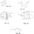
- the major structural componentsincluding OML Outer Skin 37 including WTB fairing 14, IML inner skin 39 including WTB volume extension 49 shown in FIGs. 3B , 7 and 8 , crown longeron 32, FIG. 9A , keel longeron 34, FIG. 9B , aft pressure bulkhead (APB) BL0 rib 61, FIG.
- FIG. 9Cdoor surrounds 63, 64, 65, 66, 67, FIGs. 9D and 9E , composite build up flight deck half 71 including flight deck bulkhead (FDBH) 72, FIG. 9F , composite build up aft galley half 75 including cargo region surround structure 76, FIG. 9G , and composite build up main landing gear wheel well 77 (MLGWW), FIG. 9H are fabricated with the multi-part mandrels on the interior concave surface, and the caul plates on the outermost surface, step 1102.
- FDBHflight deck bulkhead
- FIG. 9Fcomposite build up aft galley half 75 including cargo region surround structure 76
- FIG. 9Gcomposite build up main landing gear wheel well 77
- FIG. 9Hare fabricated with the multi-part mandrels on the interior concave surface, and the caul plates on the outermost surface, step 1102.
- the CFRP partsare individually cured using either normal autoclave equipment or compression heat blanket equipment. Removing the various parts from both the mandrel and caul is only partially completed, allowing the Inner Skin IML mandrel tooling to become a rigid datum for the multiple other parts to be beneficially combined in the post cure bonding process, step 1104.
- the caul platesare removed from the Inner Skin 39, FDBH 71, Aft Galley 75 and MLGWW 77.
- the mandrelsare removed from the Outer Skin 37, the Longerons 32 and 34, the APB rib 61, and Door Surrounds 63, 64, 65, 66, 67.
- each mating surfaceis exposed and prepared for adhesive bonding, step 1106, and then coated with bonding compound, typically epoxy, step 1108.
- bonding compoundtypically epoxy
- Prefabricated segments of fiberglass honeycomb core 38 coated with an unexpanded thermo-expandable materialare milled to match a 4" to 7" designed gap between the outer skin 37 and inner skin 39 and other components listed above, step 1110.
- Exemplary material for the core 38is disclosed in US 7,842,147 to Gill.
- the milled honeycomb segmentsare arranged on the cured inner skin 39 surface with the longitudinal axis of the cells oriented radially from the longitudinal axis of the airplane, perpendicular to the inner skin and outer skin surfaces, step 1112.
- the density and structural properties of each core segmentmatch the required loading or each region of the fuselage assembly.
- the componentsare rigidly and accurately aligned such that the core material is completely enclosed, step 1114.
- the locked assemblyis heated to both cure the bonding compound and also to expand the thermally activated foaming agent within the core cell interstitial spaces, step 1116.
- the resulting one-piece fuselage half section 36is then removed from the tooling, step 118.
- the fuselage half sectionhas beneficially integrated the outer aerodynamic skin 37, the intermediate core 38 providing depth of section, and a structural inner skin 39 which is the interior lining of the passenger area 22 including the volume extension 39 provided by the extension into the WTB fairing 14.
- the monocoque constructionhas inherent damage tolerance, duplicate load paths, foam filled interstitial space to prevent moisture ingress, and noise and thermal insulation, while providing the essential purpose of a structure which carries all flight loads and which simultaneously provides an irregular elliptical shaped membrane capable of holding internal pressurization without additional stiffening.
Landscapes
- Engineering & Computer Science (AREA)
- Mechanical Engineering (AREA)
- Aviation & Aerospace Engineering (AREA)
- Laminated Bodies (AREA)
Description
- Embodiments of the disclosure relate generally to the field of aircraft fuselage design and more particularly to a fuselage having substantially elliptical cross section and planform integrating available volume in wing to body aerodynamic fairings for additional payload volume.
- Use of composite structures in aircraft fuselages is allowing significant flexibility in design to accommodate alternative aerodynamic and structural configurations. Medium sized aircraft are widely used to carry at least 100 passengers and their baggage on flights usually of multiple hour duration, but are also often used for short flights between islands or congested metropolitan regions. Redesign of aircraft in this class to maximize passenger loading capability and provide desirable baggage compartment locations and accessibility while improving aerodynamic performance with reduced wetted area for fuel efficiency and cost savings is advantageous.
- It is therefore desirable to provide a structural design for a medium sized aircraft fuselage having reduced wetted area with maximum volume.
CH700723 - According to a first aspect of the present invention there is provided a passenger plane as claimed in claim 1. According to a second aspect of the invention, there is provided a method for fabrication of an aircraft passenger cabin of a passenger aircraft according to the first aspect, as claimed in claim 8.
- Embodiments disclosed herein provide an aircraft passenger cabin in a fuselage wherein an upper portion of the cabin volume is a substantially elliptical cross section and a lower portion of the cabin volume is a cross section extending laterally into a blended area of the wing and fuselage typically referred to as a wing to body fairing.
- In one example a passenger airplane incorporates a fuselage accommodating an interior pressurized passenger cabin containing a plurality of rows of passenger seats. The fuselage has an upper cross section shape and lower cross section shape defining a fuselage structural shell. The upper cross section shape has a non-circular, elliptical cross section. The lower cross section shape contains a pressurized volume within the wing to body fairing that is integrated into the interior pressurized passenger cabin. The wings are advantageously coupled to the lower cross section to create a substantially rectangular pressurized volume while also beneficially distributing a portion of the flight loads into the structure of the upper section.
- The disclosed embodiment is envisioned to be the basis for a person skilled in the art to derive designs of smaller and also significantly larger capacity by simultaneously modifying the major axis of the ellipse in the Y axis and also the X axis while the Z axis shape remains substantially unchanged. The features, functions, and advantages that have been discussed may be combined in yet other embodiments further details of which can be seen with reference to the following description and drawings. The example embodiment discloses an aircraft of approximately 175 passengers.
- Advantageously, the non-circular elliptical cross section has a horizontal major axis greater than two (2) times a vertical minor axis, and further comprising the main landing gear and nose landing gear, and at least two engines; wherein the main landing gear is beneficially located outside of and adjacent to the pressurized volume for beneficial main cabin use and within the minimum wetted area and profile of the aircraft; wherein a floor of the passenger cabin is between 66 to 70 inches above ground level when the main and nose landing gears are deployed; wherein the wing to body fairing further comprises an enlargement of a lower portion of the pressurized passenger cabin to provide passenger seating up to the major diameter of the elliptical cross section; wherein the enlargement of the lower portion of the pressurized passenger cabin extends beyond a major diameter of the elliptical cross section; wherein the fuselage has a substantially elliptical planform; wherein a major axis of the substantially elliptical planform is greater than two times a minor axis of the substantially elliptical planform; wherein a minor axis of the elliptical planform terminates adjacent the wing to body fairing; wherein the fuselage incorporates a single crown longeron; wherein the fuselage incorporates a single keel longeron; wherein a baggage compartment is aft of an occupied portion of the passenger cabin; and, wherein engines are mounted to the fuselage adjacent the baggage compartment.
- According to yet another advantageous embodiment, the cross section of the lower volume extends laterally beyond the width of a major axis of the substantially elliptical upper cross section. Further, the aircraft passenger cabin has a substantially flat floor extending laterally at least the width of a major axis of the substantially elliptical cross section of the upper volume; wherein a major axis of the elliptical cross section is at least two times a minor axis: and has a single main volume.
- In yet still another advantageous embodiment, there is provided a method for fabrication of the passenger cabin of the airplane according to the invention having laterally extended pressurized volume in a WTB fairing comprising: fabricating the major structural components including an outer skin having a WTB fairing and an inner skin having an volume extension into the WTB fairing with multi-part mandrels on each interior concave surface, and caul plates on each outermost surface; curing the components and removing various selected mandrels and cauls from the components, allowing an inner skin IML mandrel to become a rigid datum in a post cure bonding process; exposing and preparing each mating surface for adhesive bonding; coating each mating surface with bonding compound; milling prefabricated segments of fiberglass honeycomb core coated with an unexpanded thermo-expandable material to match to match a gap between the outer skin and inner skin; aligning and locking the components such that the core material is completely enclosed; and, heating the locked components to cure the bonding compound and to expand the thermally activated foaming agent.
- Further, wherein the step of milling the core comprises arranging the milled honeycomb segments on the cured inner skin surface with the longitudinal axis of the cells oriented radially from a longitudinal axis of the airplane, perpendicular to the inner skin and outer skin surfaces; wherein the step of fabricating the major structural components further includes fabricating a crown longeron, a keel longeron , an aft pressure bulkhead (APB) rib and door surrounds; wherein the step of fabricating the major structural components further includes fabricating a composite build up flight deck half, a composite build up aft galley half and a composite build up main landing gear wheel well.
- The features, functions, and advantages that have been discussed may be combined in yet other embodiments further details of which can be seen with reference to the following description and drawings.
FIG. 1 is a front view of an aircraft employing an example embodiment;FIG. 2 is a top view of the embodiment;FIG. 3A is a front section view of the embodiment at the minor planform elliptical axis;FIG. 3B is a front oblique section view of the embodiment along lineFIG.3B - FIG.3B inFIG. 2 ;FIG. 4 is a side section view of the embodiment;FIG. 5 is a top section view of the embodiment;FIG. 6 is an isometric side section view of an example fuselage half employing the described embodiment;FIG. 7 is an isometric view of an outer skin;FIG. 8 is an isometric view of an inner skin;FIGs. 9A- 9H are isometric views of major structural components for assembly with the inner and outer skin;FIGs. 10A and10B are section views of the assembled components; and,FIG. 11 is a flow chart of an exemplary fabrication method for the skins and components.- Embodiments disclosed herein provide a novel interior arrangement in a mid-sized elliptical fuselage airplane using a pressurized volume in the wing-to-body (WTB) fairing to permit a wide-body multi aisle seating arrangement in a medium sized aircraft typically used for regional routes. The configuration provides reduced wetted area of the airframe while keeping the same payloads volume and a desired ground height since the fuselage shape can be made shorter and wider. The outboard portion of a highly elliptical fuselage cross section is not suitable for passenger seating. However, by incorporating a portion of the WTB fairing volume within the passenger compartment, extended space becomes available which is usable for additional seating. This is, in effect, an integration of the several factors of elliptical fuselage cross section and plan form, extension of pressurized payload volume into WTB, blended wing with forward strake aerodynamic surfaces, and thick core sandwich primary structure to produce a uniquely successful airplane of high aerodynamic and structural efficiency and compatibility with multiple large diameter fuel efficient propulsion systems.
- As seen in
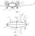
FIGs. 1 and 2 ,fuselage 10 ofaircraft 12 has a substantially elliptical cross-section and planform which is distinct from conventional circular cylindrical fuselages in present commercial aircraft. A wing to fuselageinterface employing fairings 14 blends the shape offuselage 10 into the shape of thewings 16 extending from the fuselage in a conventional manner. Thefairings 14 extend forward of the wings instrakes 18 for aerodynamic shaping establishing a blended wing body (BWB) configuration. The shorter and wider shape of the dual elliptical fuselage form allows wetted area of the airframe to be reduced while keeping the same payloads volume and a desiredlower ground height 19. For the embodiment shown, the twomain propulsion engines 20 attach adjacent to the fuselage aft of the main occupiedcabin 22 in order to provide improved perceived noise level and rotor-burst safety, and to allow versatility in engine choice including such designs as a 14' diameter unducted fan (UDF or Propfan) or a geared turbofan (GTF) class 10' diameter propulsion engine without requiring an increase in the ground height of the wing or fuselage. - As shown in
FIGs. 3A, 3B ,4 and5 , the fuselage basic shape approximates both a near-elliptical cross-section 24 and a near-elliptical plan-form 26 for a structural shell. The cross section ellipticalmajor axis 28 is more than two (2) times theminor axis 29, the major axis being horizontal and the minor axis being vertical. Similarly, the plan-formmajor axis 30 is more than two times theminor axis 31, the major axis being longitudinal length and the minor axis being lateral width. - Preferred structural embodiments employ both sandwich structure and a primary load carrying structure employing a
single crown longeron 32 and asingle keel longeron 34 instead of a conventional skin-stringer structure. Structural joining with a longitudinal splice at the fuselage keel and crown instead of circular splices as in a conventional aircraft fuselage enhances the joint strength and also more effectively serves alternate purposes for energy absorbing deformation loads, gust loads and other structural requirements. Thecrown longeron 32 andkeel longeron 34 act as the webs of structural crown andkeel beams crown beam 33 andkeel beam 35 beneficially distribute loads along the main cabin in the longitudinal direction. As shown inFIG. 6 , for an example embodimentfuselage half sections 36 are fabricated and then bonded at the crown and keel. - As will be described in greater detail subsequently, for the example embodiment the aircraft primary structure is composed of a structural outer skin, a very thick and lightweight core, and a structural inner skin. The outer carbon fiber reinforced polymer (CFRP)
skin 37 defines the outer mold line (OML) of the aircraft and is smooth without longitudinal (X axis) manufacturing breaks and also without through fasteners to additional support frames and stringers found on currently available aircraft. The outer skin has integrated inboard thickness increases where necessary for window and door cutouts, and local reinforcement for antennae and tear stops which incorporate a thickened band on the fuselage. If a tear begins, it will eventually get to one of the thickened bands and the tear will not continue to grow in length. Acore 38 for an example embodiment is made of a strong and lightweight fiberglass honeycomb which is milled to the exact surface profile required to match the inner and outer skins. Multiple milled blocks of honeycomb are joined with septum sheets as required to contiguously fill the entirefuselage half section 36. The honeycomb interstitials are beneficially filled with foam to prevent moisture ingress. An inner carbon fiber reinforced polymer (CFRP)skin 39 defines the inner mold line (IML) of the aircraft interior and is the smooth surface immediately adjacent to the aircraft payload. The door and window surrounding structure is bonded to the inner and outer skins to act similar to the webs of the longerons to bridge structural loads. The skin buildup and crown/keel longerons form a structural shell having the substantially elliptical planform and cross section with an upper elliptical portion and a lower laterally extended portion in the passenger cabin adjacent the WTB fairings. - The volume of the
WTB fairing 14 is integrated into the aircraft cabin for pressurized payload such that an exampleoverall cross-section 40 of the lower portion of the passenger compartment shown inFIG. 3A extends downward in a substantially squared corner allowing thewidth 41 ofcompartment floor 42 to be approximately the same or greater than themajor axis 28. The passenger compartment cross section in the portion of the fuselage adjacent the WTB fairings is substantially elliptical above the major axis for anupper cross section 43 and substantially rectangular below the major axis for thelower cross section 40. This allows more passenger seats or other payloads to be arranged within the same aircraft wetted area. As seen inFIG. 3A if theelliptical section 24 limited the usable area,outboard seats 44 could not be installed. By extending the interior cabin sidewall downward within the WTB fairing profile for laterally extended volume shown byprofile 46 theoutboard seats 44 may be installed. The volumetric capacity of the fuselage is further optimized by the confluence of the position of the arcuate portion of the planform ellipse about the extent ofminor axis 29 within the longitudinal length of the WTB fairings. For the embodiment as shown inFIG. 5 , a 3-5-3 seating arrangement can be accommodated in the laterally extended portion (generally designated 48 inFIG. 5 ) of thecabin 22 adjacent the WTB fairings. A substantially squared corner is shown for the example embodiment. Further lateral extension of the cabin beyond the major axis of the elliptical planform by extending the sidewall into the area of the fairing for the lower cross section shown byprofile 49 inFIG. 3B could allow additional floor mounted baggage storage compartments adjacent theoutboard seats 44 or other cabin interior space usage. - The highly elliptical fuselage allows a twin aisle aircraft with a main compartment floor in close proximity to the keel to provide improved ground access for payloads loading and unloading and maintenance. For the example embodiment of a medium sized aircraft shown in
FIGs. 3A, 3B ,4 and5 , the substantially flat floor of the passenger compartment is approximately 66 to 70 inches above ground level.Nose landing gear 50 andmain landing gear 52 may be comparable to current 100 passenger aircraft in length and may further enhance the desired low keel height by having a kneeling capability. The additional volume available inWTB fairings 14 provides retraction volume for the main landing gear which is advantageously arranged outside of and adjacent to the pressurized expanded volume so as to avoid the common problem of a decrease in the space available for beneficial main cabin use, while allowing the minimum wetted area and profile of the aircraft. The kneeling main landing gear can be beneficially arranged to allow substantially more vertical movement for absorption of landing loads than is commonly available on existing medium sized passenger aircraft and also a simple and substantially vertical retraction path. - As seen in
FIGs. 4 and5 , thecargo compartment 54 is located aft of the mainoccupied cabin 22 similar to the arrangement used on many smaller regional aircraft. A further benefit of this arrangement is to locate the main propulsion engines adjacent to the section of the fuselage aft of the main occupied cabin and adjacent the cargo compartment in order to provide improved perceived noise level and rotor-burst safety, and to allow a very large diameter propulsion engine 20 (e.g. 10' dia. GTF) without requiring an increase in the height of the wing or fuselage. - As also seen in
FIGs. 3A and 3B shaping of the fuselage as described has significant beneficial effect in the overall usability and efficiency of the passenger cabin area. The structure of thecrown longeron 32 is highly compatible with placement and structural support of internalbaggage stowage bins 56 and other aircraft systems routing such asventilation ducting 58. The rectangularlower cross section 40 supported by thekeel longeron 34 allows thefloor 42 to be substantially flat for at least the entire width of the laterally extendedcabin portion 48. - For fabrication of the major structural components of an exemplary embodiment of the aircraft fuselage having laterally extended pressurized volume in the WTB fairing as described, the outer skin, the thick core, and the inner skin are bonded to create a single, monolithic structure. An exemplary embodiment of the method described with respect to
FIGs. 7 ,8 ,9A - 9H ,10A ,10B , for visualization of the components andFIG. 11 as a flowchart uses existing technology tape laying machines to compressively apply a plurality of tailored plies of high strength CFRP composite to a rigid tooling mandrel, which is then covered with a semi-flexible caul plate with release agents. The mandrel and caul plate tooling for the OMLouter skin 37 and the IMLinner skin 39 have door and window cutouts beneficially arranged with rigid features for alignment of subsequent components as shown inFIGs. 7 and8 . Each of the components has a Left Hand and Right Hand manifestation using tooling mirrored about the buttline 0 (BL0) centerline plane. The major structural components includingOML Outer Skin 37 includingWTB fairing 14, IMLinner skin 39 includingWTB volume extension 49 shown inFIGs. 3B ,7 and8 ,crown longeron 32,FIG. 9A ,keel longeron 34,FIG. 9B , aft pressure bulkhead (APB)BL0 rib 61,FIG. 9C , door surrounds 63, 64, 65, 66, 67,FIGs. 9D and 9E , composite build upflight deck half 71 including flight deck bulkhead (FDBH) 72,FIG. 9F , composite build upaft galley half 75 including cargoregion surround structure 76,FIG. 9G , and composite build up main landing gear wheel well 77 (MLGWW),FIG. 9H are fabricated with the multi-part mandrels on the interior concave surface, and the caul plates on the outermost surface,step 1102. - The CFRP parts are individually cured using either normal autoclave equipment or compression heat blanket equipment. Removing the various parts from both the mandrel and caul is only partially completed, allowing the Inner Skin IML mandrel tooling to become a rigid datum for the multiple other parts to be beneficially combined in the post cure bonding process,
step 1104. The caul plates are removed from theInner Skin 39,FDBH 71,Aft Galley 75 andMLGWW 77. The mandrels are removed from theOuter Skin 37, theLongerons APB rib 61, and Door Surrounds 63, 64, 65, 66, 67. - Each mating surface is exposed and prepared for adhesive bonding,
step 1106, and then coated with bonding compound, typically epoxy,step 1108. Prefabricated segments offiberglass honeycomb core 38 coated with an unexpanded thermo-expandable material are milled to match a 4" to 7" designed gap between theouter skin 37 andinner skin 39 and other components listed above,step 1110. Exemplary material for thecore 38 is disclosed inUS 7,842,147 to Gill. The milled honeycomb segments are arranged on the curedinner skin 39 surface with the longitudinal axis of the cells oriented radially from the longitudinal axis of the airplane, perpendicular to the inner skin and outer skin surfaces,step 1112. The density and structural properties of each core segment match the required loading or each region of the fuselage assembly. Using existing techniques known to those familiar with the art such as use of alignment pins and manual or hydraulic overcenter clamps, the components are rigidly and accurately aligned such that the core material is completely enclosed,step 1114. The locked assembly is heated to both cure the bonding compound and also to expand the thermally activated foaming agent within the core cell interstitial spaces,step 1116. - The resulting one-piece
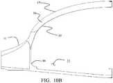
fuselage half section 36 is then removed from the tooling, step 118. As shown inFIGs. 10A and10B The fuselage half section has beneficially integrated the outeraerodynamic skin 37, theintermediate core 38 providing depth of section, and a structuralinner skin 39 which is the interior lining of thepassenger area 22 including thevolume extension 39 provided by the extension into theWTB fairing 14. The monocoque construction has inherent damage tolerance, duplicate load paths, foam filled interstitial space to prevent moisture ingress, and noise and thermal insulation, while providing the essential purpose of a structure which carries all flight loads and which simultaneously provides an irregular elliptical shaped membrane capable of holding internal pressurization without additional stiffening. - Having now described various embodiments of the disclosure in detail as required by the patent statutes, those skilled in the art will recognize modifications and substitutions to the specific embodiments disclosed herein. Such modifications are within the scope of the present disclosure as defined in the following claims.
Claims (11)
- A passenger airplane (12) comprising:a fuselage (10) accommodating an interior pressurized passenger cabin (22) containing a plurality of rows of passenger seats (44);said fuselage (10) having an upper cross section shape (24) and a lower cross section shape defining a fuselage structural shell,said upper cross section shape having a non-circular, elliptical cross section;wings (16) coupled to said lower cross section shape at a wing-to-body interface having a wing to body fairing (14);said wing to body fairing (14) containing a pressurized volume that is integrated into the lower cross section shape as part of the interior pressurized passenger cabin,wherein the wing to body fairing (14) further comprises an enlargement of a lower portion of the pressurized passenger cabin to provide passenger seating up to the horizontal major axis (28) of the elliptical cross section,characterised in that the overall cross-section (40) of the lower portion of the passenger compartment extends downward in a substantially squared corner allowing the width (41) of the compartment floor (42) to be approximately the same or greater than the major axis (28) of the non-circular elliptical cross section.
- The passenger airplane (12) of claim 1 wherein the horizontal major axis (28) of the non-circular elliptical cross section is greater than two (2) times its vertical minor axis (29).
- The passenger airplane (12) of claim 1 or 2 further comprising main landing gear (52) and nose landing gear (50), and at least two engines (20), wherein the main landing gear (52) is beneficially located outside of and adjacent to the pressurized volume for beneficial main cabin (22) use and within the minimum wetted area and profile of the aircraft (12).
- The passenger airplane (12) of any preceding claim, wherein a floor (42) of the passenger cabin (22) is between 66 to 70 inches above ground level when the main and nose landing gears (50, 52) are deployed.
- The passenger airplane (12) of any preceding claim wherein the enlargement of the lower portion of the pressurized passenger cabin (22) extends beyond the major axis (28) of the elliptical cross section.
- The passenger airplane (12) of any preceding claim wherein the fuselage (10) has a substantially elliptical planform; wherein a major axis (30) of the substantially elliptical planform is greater than two times a minor axis (31) of the substantially elliptical planform; and, wherein a minor axis (31) of the elliptical planform terminates adjacent the wing to body fairing (14).
- The passenger airplane (12) of any preceding claim wherein the fuselage (10) incorporates a single crown longeron (32); wherein the fuselage (10) incorporates a single keel longeron (34); wherein a baggage compartment is aft of an occupied portion of the passenger cabin (22); and, wherein engines (20) are mounted to the fuselage (10) adjacent the baggage compartment.
- A method of fabrication of the passenger cabin (22) of a passenger airplane (12) as claimed in any one of claims 1 to 7, the cabin having laterally extended pressurized volume in the WTB fairing (14) comprising:fabricating the major structural components including an outer skin (37) having the WTB fairing (14) and an inner skin (39) having an volume extension into the WTB fairing (14) with multi-part mandrels on each interior concave surface, and caul plates on each outermost surface ;curing the components and removing various selected mandrels and cauls from the components, allowing an inner skin IML mandrel to become a rigid datum in a post cure bonding process;exposing and preparing each mating surface for adhesive bonding;coating each mating surface with bonding compound;milling prefabricated segments of fiberglass honeycomb core coated with an unexpanded thermo-expandable material to match to match a gap between the outer skin and inner skin;aligning and locking the components such that the core material is completely enclosed; and,heating the locked components to cure the bonding compound and to expand the thermally activated foaming agent.
- The method as defined in claim 8 wherein the step of milling the core comprises arranging the milled honeycomb segments on the cured inner skin surface (39) with the longitudinal axis of the cells oriented radially from a longitudinal axis of the airplane, perpendicular to the inner skin and outer skin surfaces (37, 39).
- The method as defined in claims 8 or 9 wherein the step of fabricating the major structural components further includes fabricating a crown longeron (32), a keel longeron (34), an aft pressure bulkhead (APB) rib (61) and door surrounds (63, 64, 65, 66, 67).
- The method as defined in claims 8 to 10 wherein the step of fabricating the major structural components further includes fabricating a composite build up flight deck half (71), a composite build up aft galley half (75) and a composite build up main landing gear wheel well (77).
Applications Claiming Priority (1)
| Application Number | Priority Date | Filing Date | Title |
|---|---|---|---|
| US13/293,958US8608109B2 (en) | 2011-11-10 | 2011-11-10 | Payload use of wing to body volume in an elliptical fuselage |
Publications (2)
| Publication Number | Publication Date |
|---|---|
| EP2591996A1 EP2591996A1 (en) | 2013-05-15 |
| EP2591996B1true EP2591996B1 (en) | 2017-01-18 |
Family
ID=47226025
Family Applications (1)
| Application Number | Title | Priority Date | Filing Date |
|---|---|---|---|
| EP12192304.9ANot-in-forceEP2591996B1 (en) | 2011-11-10 | 2012-11-12 | Elliptical fuselage with wing to body volume integrated in pressurised cabin |
Country Status (2)
| Country | Link |
|---|---|
| US (1) | US8608109B2 (en) |
| EP (1) | EP2591996B1 (en) |
Families Citing this family (18)
| Publication number | Priority date | Publication date | Assignee | Title |
|---|---|---|---|---|
| FR2906523B1 (en)* | 2006-09-29 | 2009-11-27 | Airbus | AIRCRAFT COMPRISING A FUSELAGE WITH FLOOR EXTENDING IN THE LONGITUDINAL PLAN OF FUSELAGE. |
| US9650127B2 (en) | 2013-03-13 | 2017-05-16 | The United States Of America As Represented By The Administration Of The National Aeronautics And Space Administration | Stretchable mesh for cavity noise reduction |
| US10201847B2 (en)* | 2014-07-09 | 2019-02-12 | The Boeing Company | Clamping feet for an end effector |
| US10946962B2 (en) | 2015-12-09 | 2021-03-16 | Bombardier Inc. | Blended wing body aircraft |
| US11613356B2 (en) | 2015-12-09 | 2023-03-28 | Bombardier Inc. | Blended wing body aircraft |
| US11453483B2 (en)* | 2016-06-30 | 2022-09-27 | Blended Wing Aircraft, Inc. | Aircraft for commercial air travel and a method of manufacture |
| US20230278706A1 (en)* | 2016-06-30 | 2023-09-07 | Jetzero, Inc. | An aircraft with a mid-market passenger capacity and a method of manufacture |
| US10273003B2 (en)* | 2017-04-14 | 2019-04-30 | Britton COULSON | Multi-tank system for aerial firefighting aircraft |
| US11148780B2 (en)* | 2017-12-21 | 2021-10-19 | Aurora Flight Sciences Corporation | Aircraft fuselage and structural cable for aircraft fuselage |
| US12275526B2 (en)* | 2018-06-15 | 2025-04-15 | Zeva Inc. | Electric vertical take-off and landing blended wing-body aircraft |
| WO2020142337A1 (en)* | 2018-12-31 | 2020-07-09 | DZYNE Technologies Incorporated | Emergency egress in a blended wing body aircraft |
| CN109878692B (en)* | 2019-02-28 | 2022-03-04 | 西北工业大学 | A self-air-tight airbag device for non-circular section pressurized cabin sharp corners |
| AT525878B1 (en)* | 2022-03-24 | 2023-09-15 | Johannes Kepler Univ Linz | vehicle |
| US12391371B2 (en)* | 2022-10-03 | 2025-08-19 | Jetzero, Inc. | Aircraft with outboard-stowed landing gear |
| US11952097B1 (en)* | 2023-05-25 | 2024-04-09 | Jetzero, Inc. | Blended wing body aircraft |
| US20250214703A1 (en)* | 2023-12-29 | 2025-07-03 | Rtx Corporation | Blended wing body aircraft system |
| US12187425B1 (en) | 2024-01-19 | 2025-01-07 | Jetzero, Inc. | Aircraft component with structural foam |
| US20250256833A1 (en)* | 2024-02-09 | 2025-08-14 | Rtx Corporation | Aircraft vertical stabilizer with moveable propulsion system(s) |
Family Cites Families (23)
| Publication number | Priority date | Publication date | Assignee | Title |
|---|---|---|---|---|
| FR1460060A (en) | 1965-10-15 | 1966-06-17 | Nord Aviation | Large capacity fuselage and corresponding aerodyne |
| GB1397068A (en) | 1971-06-24 | 1975-06-11 | Hawker Siddeley Aviation Ltd | Aircraft |
| US3854679A (en)* | 1974-01-07 | 1974-12-17 | Lockheed Aircraft Corp | Water-based airplane especially designed for adaptation to stol |
| US4674712A (en)* | 1985-01-22 | 1987-06-23 | The Boeing Company | Double-lobe fuselage composite airplane |
| FR2649665B1 (en)* | 1989-07-12 | 1991-11-08 | Airbus Ind | LARGE CAPACITY FUSELAGE FOR AIRCRAFT |
| US6047923A (en)* | 1995-01-13 | 2000-04-11 | Trimbach Turbine, Ltd. | Aircraft having multiple fuselages |
| US5769358A (en)* | 1996-05-13 | 1998-06-23 | Redwood Aircraft Corporation | Lifting-fuselage/wing aircraft having an elliptical forebody |
| US6394392B1 (en)* | 1999-10-19 | 2002-05-28 | Trimbach Turbine, Ltd. | Aircraft having multiple fuselages |
| US6568632B2 (en)* | 2001-04-04 | 2003-05-27 | The Boeing Company | Variable size blended wing body aircraft |
| US6866225B2 (en)* | 2003-04-30 | 2005-03-15 | The Boeing Company | Method and system for presenting moving simulated images in a moving vehicle |
| US7046259B2 (en)* | 2003-04-30 | 2006-05-16 | The Boeing Company | Method and system for presenting different views to passengers in a moving vehicle |
| US7093798B2 (en)* | 2004-01-30 | 2006-08-22 | The Boeing Company | Transformable airplane |
| US7556219B2 (en)* | 2004-02-24 | 2009-07-07 | Swift Engineering, Inc. | Unmanned aerial vehicle and launch assembly |
| JP4441826B2 (en)* | 2004-03-29 | 2010-03-31 | ウィリアム・ディー・リーケン | Aircraft with ring-shaped wing structure |
| US8292226B2 (en)* | 2005-11-15 | 2012-10-23 | The Boeing Company | Weight-optimizing internally pressurized composite-body aircraft fuselages having near-elliptical cross sections |
| US7621482B2 (en)* | 2005-11-15 | 2009-11-24 | The Boeing Company | Weight optimized pressurizable aircraft fuselage structures having near elliptical cross sections |
| US7842147B2 (en) | 2007-01-31 | 2010-11-30 | M.C. Gill Corporation | Composite panel having in-situ thermoset foamed core |
| FR2915459B1 (en) | 2007-04-25 | 2009-09-25 | Airbus France Sas | LARGE FUSELAGE AIRCRAFT ARCHITECTURE |
| CH700723B1 (en) | 2007-09-11 | 2010-10-15 | Hanspeter John Mueller | Airplane, particularly air carrier, comprises fuselage area, main wing area, and tail wing area, where tail wing area and fuselage area forms part of aerodynamically carrying wing areas |
| FR2943039B1 (en)* | 2009-03-12 | 2012-09-28 | Airbus France | PLANE TANK-TAIL AND REVERSE ENGINE. |
| US8403256B1 (en)* | 2009-03-25 | 2013-03-26 | The Boeing Company | Swept-wing powered-lift aircraft |
| US8366050B2 (en)* | 2009-11-21 | 2013-02-05 | The Boeing Company | Blended wing body cargo airplane |
| GB201004803D0 (en)* | 2010-03-23 | 2010-05-05 | Deakin Nicholas J | Aerial vehicle and method of flight |
- 2011
- 2011-11-10USUS13/293,958patent/US8608109B2/ennot_activeExpired - Fee Related
- 2012
- 2012-11-12EPEP12192304.9Apatent/EP2591996B1/ennot_activeNot-in-force
Non-Patent Citations (1)
| Title |
|---|
| None* |
Also Published As
| Publication number | Publication date |
|---|---|
| US20130119198A1 (en) | 2013-05-16 |
| US8608109B2 (en) | 2013-12-17 |
| EP2591996A1 (en) | 2013-05-15 |
Similar Documents
| Publication | Publication Date | Title |
|---|---|---|
| EP2591996B1 (en) | Elliptical fuselage with wing to body volume integrated in pressurised cabin | |
| US11312472B2 (en) | Wing structure | |
| US10889363B2 (en) | Efficient sub-structures | |
| US8746616B2 (en) | Mid-wing multi-deck airplane | |
| US7735779B2 (en) | Optimized fuselage structure | |
| US9187169B2 (en) | High-wing-aircraft fuselage support structure | |
| US8899520B2 (en) | Mid-wing airplane | |
| US4674712A (en) | Double-lobe fuselage composite airplane | |
| CN103813959B (en) | helicopter | |
| US9808996B2 (en) | Stabilizer torque box assembly and method | |
| EP3031711B1 (en) | Aircraft frame for tailstrike angle enhancement | |
| EP3415414B1 (en) | Wing-to-fuselage joints and aircraft including the same | |
| EP2076431B1 (en) | Wing panel structure | |
| WO2007099297A1 (en) | Aircraft wings and their assembly | |
| Howe | Blended wing body airframe mass prediction | |
| EP3501970B1 (en) | Aircraft fuselage and structural cable for aircraft fuselage | |
| US20210031903A1 (en) | Nose structure for an aircraft and method of making an aircraft | |
| EP3549853A1 (en) | Aircraft fuselage with composite pre-form | |
| CN113955071A (en) | Aircraft fuselage, forming method thereof and aircraft | |
| US12269606B2 (en) | Aircraft | |
| US11014691B2 (en) | Nose structure for an aircraft and method of making an aircraft | |
| WO2013137915A1 (en) | Mid-wing airplane | |
| Velicki et al. | Blended wing body structural concept development | |
| EP3778378B1 (en) | Nose structure for an aircraft and method of making an aircraft | |
| Nelson | Composite wing conceptual design |
Legal Events
| Date | Code | Title | Description |
|---|---|---|---|
| PUAI | Public reference made under article 153(3) epc to a published international application that has entered the european phase | Free format text:ORIGINAL CODE: 0009012 | |
| 17P | Request for examination filed | Effective date:20121112 | |
| AK | Designated contracting states | Kind code of ref document:A1 Designated state(s):AL AT BE BG CH CY CZ DE DK EE ES FI FR GB GR HR HU IE IS IT LI LT LU LV MC MK MT NL NO PL PT RO RS SE SI SK SM TR | |
| AX | Request for extension of the european patent | Extension state:BA ME | |
| 17Q | First examination report despatched | Effective date:20151201 | |
| GRAP | Despatch of communication of intention to grant a patent | Free format text:ORIGINAL CODE: EPIDOSNIGR1 | |
| INTG | Intention to grant announced | Effective date:20160810 | |
| GRAS | Grant fee paid | Free format text:ORIGINAL CODE: EPIDOSNIGR3 | |
| GRAA | (expected) grant | Free format text:ORIGINAL CODE: 0009210 | |
| AK | Designated contracting states | Kind code of ref document:B1 Designated state(s):AL AT BE BG CH CY CZ DE DK EE ES FI FR GB GR HR HU IE IS IT LI LT LU LV MC MK MT NL NO PL PT RO RS SE SI SK SM TR | |
| REG | Reference to a national code | Ref country code:GB Ref legal event code:FG4D | |
| REG | Reference to a national code | Ref country code:CH Ref legal event code:EP | |
| REG | Reference to a national code | Ref country code:AT Ref legal event code:REF Ref document number:862736 Country of ref document:AT Kind code of ref document:T Effective date:20170215 | |
| REG | Reference to a national code | Ref country code:IE Ref legal event code:FG4D | |
| REG | Reference to a national code | Ref country code:DE Ref legal event code:R096 Ref document number:602012027934 Country of ref document:DE | |
| REG | Reference to a national code | Ref country code:NL Ref legal event code:MP Effective date:20170118 | |
| REG | Reference to a national code | Ref country code:LT Ref legal event code:MG4D | |
| REG | Reference to a national code | Ref country code:AT Ref legal event code:MK05 Ref document number:862736 Country of ref document:AT Kind code of ref document:T Effective date:20170118 | |
| PG25 | Lapsed in a contracting state [announced via postgrant information from national office to epo] | Ref country code:NL Free format text:LAPSE BECAUSE OF FAILURE TO SUBMIT A TRANSLATION OF THE DESCRIPTION OR TO PAY THE FEE WITHIN THE PRESCRIBED TIME-LIMIT Effective date:20170118 | |
| PG25 | Lapsed in a contracting state [announced via postgrant information from national office to epo] | Ref country code:LT Free format text:LAPSE BECAUSE OF FAILURE TO SUBMIT A TRANSLATION OF THE DESCRIPTION OR TO PAY THE FEE WITHIN THE PRESCRIBED TIME-LIMIT Effective date:20170118 Ref country code:FI Free format text:LAPSE BECAUSE OF FAILURE TO SUBMIT A TRANSLATION OF THE DESCRIPTION OR TO PAY THE FEE WITHIN THE PRESCRIBED TIME-LIMIT Effective date:20170118 Ref country code:HR Free format text:LAPSE BECAUSE OF FAILURE TO SUBMIT A TRANSLATION OF THE DESCRIPTION OR TO PAY THE FEE WITHIN THE PRESCRIBED TIME-LIMIT Effective date:20170118 Ref country code:NO Free format text:LAPSE BECAUSE OF FAILURE TO SUBMIT A TRANSLATION OF THE DESCRIPTION OR TO PAY THE FEE WITHIN THE PRESCRIBED TIME-LIMIT Effective date:20170418 Ref country code:IS Free format text:LAPSE BECAUSE OF FAILURE TO SUBMIT A TRANSLATION OF THE DESCRIPTION OR TO PAY THE FEE WITHIN THE PRESCRIBED TIME-LIMIT Effective date:20170518 Ref country code:GR Free format text:LAPSE BECAUSE OF FAILURE TO SUBMIT A TRANSLATION OF THE DESCRIPTION OR TO PAY THE FEE WITHIN THE PRESCRIBED TIME-LIMIT Effective date:20170419 | |
| PG25 | Lapsed in a contracting state [announced via postgrant information from national office to epo] | Ref country code:SE Free format text:LAPSE BECAUSE OF FAILURE TO SUBMIT A TRANSLATION OF THE DESCRIPTION OR TO PAY THE FEE WITHIN THE PRESCRIBED TIME-LIMIT Effective date:20170118 Ref country code:ES Free format text:LAPSE BECAUSE OF FAILURE TO SUBMIT A TRANSLATION OF THE DESCRIPTION OR TO PAY THE FEE WITHIN THE PRESCRIBED TIME-LIMIT Effective date:20170118 Ref country code:AT Free format text:LAPSE BECAUSE OF FAILURE TO SUBMIT A TRANSLATION OF THE DESCRIPTION OR TO PAY THE FEE WITHIN THE PRESCRIBED TIME-LIMIT Effective date:20170118 Ref country code:RS Free format text:LAPSE BECAUSE OF FAILURE TO SUBMIT A TRANSLATION OF THE DESCRIPTION OR TO PAY THE FEE WITHIN THE PRESCRIBED TIME-LIMIT Effective date:20170118 Ref country code:PL Free format text:LAPSE BECAUSE OF FAILURE TO SUBMIT A TRANSLATION OF THE DESCRIPTION OR TO PAY THE FEE WITHIN THE PRESCRIBED TIME-LIMIT Effective date:20170118 Ref country code:PT Free format text:LAPSE BECAUSE OF FAILURE TO SUBMIT A TRANSLATION OF THE DESCRIPTION OR TO PAY THE FEE WITHIN THE PRESCRIBED TIME-LIMIT Effective date:20170518 Ref country code:BG Free format text:LAPSE BECAUSE OF FAILURE TO SUBMIT A TRANSLATION OF THE DESCRIPTION OR TO PAY THE FEE WITHIN THE PRESCRIBED TIME-LIMIT Effective date:20170418 Ref country code:LV Free format text:LAPSE BECAUSE OF FAILURE TO SUBMIT A TRANSLATION OF THE DESCRIPTION OR TO PAY THE FEE WITHIN THE PRESCRIBED TIME-LIMIT Effective date:20170118 | |
| REG | Reference to a national code | Ref country code:DE Ref legal event code:R097 Ref document number:602012027934 Country of ref document:DE | |
| PG25 | Lapsed in a contracting state [announced via postgrant information from national office to epo] | Ref country code:IT Free format text:LAPSE BECAUSE OF FAILURE TO SUBMIT A TRANSLATION OF THE DESCRIPTION OR TO PAY THE FEE WITHIN THE PRESCRIBED TIME-LIMIT Effective date:20170118 Ref country code:SK Free format text:LAPSE BECAUSE OF FAILURE TO SUBMIT A TRANSLATION OF THE DESCRIPTION OR TO PAY THE FEE WITHIN THE PRESCRIBED TIME-LIMIT Effective date:20170118 Ref country code:CZ Free format text:LAPSE BECAUSE OF FAILURE TO SUBMIT A TRANSLATION OF THE DESCRIPTION OR TO PAY THE FEE WITHIN THE PRESCRIBED TIME-LIMIT Effective date:20170118 Ref country code:EE Free format text:LAPSE BECAUSE OF FAILURE TO SUBMIT A TRANSLATION OF THE DESCRIPTION OR TO PAY THE FEE WITHIN THE PRESCRIBED TIME-LIMIT Effective date:20170118 Ref country code:RO Free format text:LAPSE BECAUSE OF FAILURE TO SUBMIT A TRANSLATION OF THE DESCRIPTION OR TO PAY THE FEE WITHIN THE PRESCRIBED TIME-LIMIT Effective date:20170118 | |
| PLBE | No opposition filed within time limit | Free format text:ORIGINAL CODE: 0009261 | |
| STAA | Information on the status of an ep patent application or granted ep patent | Free format text:STATUS: NO OPPOSITION FILED WITHIN TIME LIMIT | |
| REG | Reference to a national code | Ref country code:FR Ref legal event code:PLFP Year of fee payment:6 | |
| PG25 | Lapsed in a contracting state [announced via postgrant information from national office to epo] | Ref country code:DK Free format text:LAPSE BECAUSE OF FAILURE TO SUBMIT A TRANSLATION OF THE DESCRIPTION OR TO PAY THE FEE WITHIN THE PRESCRIBED TIME-LIMIT Effective date:20170118 Ref country code:SM Free format text:LAPSE BECAUSE OF FAILURE TO SUBMIT A TRANSLATION OF THE DESCRIPTION OR TO PAY THE FEE WITHIN THE PRESCRIBED TIME-LIMIT Effective date:20170118 | |
| 26N | No opposition filed | Effective date:20171019 | |
| PG25 | Lapsed in a contracting state [announced via postgrant information from national office to epo] | Ref country code:SI Free format text:LAPSE BECAUSE OF FAILURE TO SUBMIT A TRANSLATION OF THE DESCRIPTION OR TO PAY THE FEE WITHIN THE PRESCRIBED TIME-LIMIT Effective date:20170118 | |
| PG25 | Lapsed in a contracting state [announced via postgrant information from national office to epo] | Ref country code:MC Free format text:LAPSE BECAUSE OF FAILURE TO SUBMIT A TRANSLATION OF THE DESCRIPTION OR TO PAY THE FEE WITHIN THE PRESCRIBED TIME-LIMIT Effective date:20170118 | |
| PG25 | Lapsed in a contracting state [announced via postgrant information from national office to epo] | Ref country code:CH Free format text:LAPSE BECAUSE OF NON-PAYMENT OF DUE FEES Effective date:20171130 Ref country code:LI Free format text:LAPSE BECAUSE OF NON-PAYMENT OF DUE FEES Effective date:20171130 | |
| PG25 | Lapsed in a contracting state [announced via postgrant information from national office to epo] | Ref country code:LU Free format text:LAPSE BECAUSE OF NON-PAYMENT OF DUE FEES Effective date:20171112 | |
| REG | Reference to a national code | Ref country code:BE Ref legal event code:MM Effective date:20171130 | |
| REG | Reference to a national code | Ref country code:IE Ref legal event code:MM4A | |
| PG25 | Lapsed in a contracting state [announced via postgrant information from national office to epo] | Ref country code:MT Free format text:LAPSE BECAUSE OF NON-PAYMENT OF DUE FEES Effective date:20171112 | |
| PG25 | Lapsed in a contracting state [announced via postgrant information from national office to epo] | Ref country code:IE Free format text:LAPSE BECAUSE OF NON-PAYMENT OF DUE FEES Effective date:20171112 | |
| PG25 | Lapsed in a contracting state [announced via postgrant information from national office to epo] | Ref country code:BE Free format text:LAPSE BECAUSE OF NON-PAYMENT OF DUE FEES Effective date:20171130 | |
| PG25 | Lapsed in a contracting state [announced via postgrant information from national office to epo] | Ref country code:HU Free format text:LAPSE BECAUSE OF FAILURE TO SUBMIT A TRANSLATION OF THE DESCRIPTION OR TO PAY THE FEE WITHIN THE PRESCRIBED TIME-LIMIT; INVALID AB INITIO Effective date:20121112 | |
| PG25 | Lapsed in a contracting state [announced via postgrant information from national office to epo] | Ref country code:CY Free format text:LAPSE BECAUSE OF NON-PAYMENT OF DUE FEES Effective date:20170118 | |
| PG25 | Lapsed in a contracting state [announced via postgrant information from national office to epo] | Ref country code:MK Free format text:LAPSE BECAUSE OF FAILURE TO SUBMIT A TRANSLATION OF THE DESCRIPTION OR TO PAY THE FEE WITHIN THE PRESCRIBED TIME-LIMIT Effective date:20170118 | |
| PGFP | Annual fee paid to national office [announced via postgrant information from national office to epo] | Ref country code:DE Payment date:20191127 Year of fee payment:8 | |
| PGFP | Annual fee paid to national office [announced via postgrant information from national office to epo] | Ref country code:FR Payment date:20191125 Year of fee payment:8 | |
| PG25 | Lapsed in a contracting state [announced via postgrant information from national office to epo] | Ref country code:TR Free format text:LAPSE BECAUSE OF FAILURE TO SUBMIT A TRANSLATION OF THE DESCRIPTION OR TO PAY THE FEE WITHIN THE PRESCRIBED TIME-LIMIT Effective date:20170118 | |
| PGFP | Annual fee paid to national office [announced via postgrant information from national office to epo] | Ref country code:GB Payment date:20191127 Year of fee payment:8 | |
| PG25 | Lapsed in a contracting state [announced via postgrant information from national office to epo] | Ref country code:AL Free format text:LAPSE BECAUSE OF FAILURE TO SUBMIT A TRANSLATION OF THE DESCRIPTION OR TO PAY THE FEE WITHIN THE PRESCRIBED TIME-LIMIT Effective date:20170118 | |
| REG | Reference to a national code | Ref country code:DE Ref legal event code:R082 Ref document number:602012027934 Country of ref document:DE Representative=s name:KILBURN & STRODE LLP, NL | |
| REG | Reference to a national code | Ref country code:DE Ref legal event code:R119 Ref document number:602012027934 Country of ref document:DE | |
| GBPC | Gb: european patent ceased through non-payment of renewal fee | Effective date:20201112 | |
| PG25 | Lapsed in a contracting state [announced via postgrant information from national office to epo] | Ref country code:FR Free format text:LAPSE BECAUSE OF NON-PAYMENT OF DUE FEES Effective date:20201130 | |
| PG25 | Lapsed in a contracting state [announced via postgrant information from national office to epo] | Ref country code:DE Free format text:LAPSE BECAUSE OF NON-PAYMENT OF DUE FEES Effective date:20210601 Ref country code:GB Free format text:LAPSE BECAUSE OF NON-PAYMENT OF DUE FEES Effective date:20201112 |