EP2591954A1 - Seat for motor vehicles - Google Patents
Seat for motor vehiclesDownload PDFInfo
- Publication number
- EP2591954A1 EP2591954A1EP12185437.6AEP12185437AEP2591954A1EP 2591954 A1EP2591954 A1EP 2591954A1EP 12185437 AEP12185437 AEP 12185437AEP 2591954 A1EP2591954 A1EP 2591954A1
- Authority
- EP
- European Patent Office
- Prior art keywords
- reinforcing material
- fixing means
- padding
- seat
- backrest
- Prior art date
- Legal status (The legal status is an assumption and is not a legal conclusion. Google has not performed a legal analysis and makes no representation as to the accuracy of the status listed.)
- Granted
Links
Images

Classifications
- B—PERFORMING OPERATIONS; TRANSPORTING
- B60—VEHICLES IN GENERAL
- B60R—VEHICLES, VEHICLE FITTINGS, OR VEHICLE PARTS, NOT OTHERWISE PROVIDED FOR
- B60R21/00—Arrangements or fittings on vehicles for protecting or preventing injuries to occupants or pedestrians in case of accidents or other traffic risks
- B60R21/02—Occupant safety arrangements or fittings, e.g. crash pads
- B60R21/16—Inflatable occupant restraints or confinements designed to inflate upon impact or impending impact, e.g. air bags
- B60R21/20—Arrangements for storing inflatable members in their non-use or deflated condition; Arrangement or mounting of air bag modules or components
- B60R21/207—Arrangements for storing inflatable members in their non-use or deflated condition; Arrangement or mounting of air bag modules or components in vehicle seats
- B—PERFORMING OPERATIONS; TRANSPORTING
- B60—VEHICLES IN GENERAL
- B60N—SEATS SPECIALLY ADAPTED FOR VEHICLES; VEHICLE PASSENGER ACCOMMODATION NOT OTHERWISE PROVIDED FOR
- B60N2/00—Seats specially adapted for vehicles; Arrangement or mounting of seats in vehicles
- B60N2/58—Seat coverings
- B60N2/5816—Seat coverings attachments thereof
- B60N2/5825—Seat coverings attachments thereof by hooks, staples, clips, snap fasteners or the like
- B—PERFORMING OPERATIONS; TRANSPORTING
- B60—VEHICLES IN GENERAL
- B60N—SEATS SPECIALLY ADAPTED FOR VEHICLES; VEHICLE PASSENGER ACCOMMODATION NOT OTHERWISE PROVIDED FOR
- B60N2/00—Seats specially adapted for vehicles; Arrangement or mounting of seats in vehicles
- B60N2/58—Seat coverings
- B60N2002/5808—Seat coverings comprising opening zones for airbags
Definitions
- the present inventionrelates to a seat for motor vehicles.
- a problem with such an embodimentis that the tearing, i. the tearing speed and also the appearance of the cover of the vehicle seat and the tear seam depends on the cover material, the suture and the type of seams.
- the opening of the tear seam and the deployment of the airbag devicemust be predictable. independence from the reference used should also be ensured.
- the seat coversare equipped with so-called unfolding / positioning aids made of a less stretchable material.
- the present inventionhas for its object to provide a seat with a arranged in a receiving space of the side region airbag device such that a simple and cost-effective production of the device and assembly of the components is possible, with a functionally reliable, predictable tearing of the tear seam is ensured at different seat cover materials ,
- the reinforcing material layersare fastened to the backrest at their edge region opposite the seam line by means of fixing means and form a side cheek cushion with airbag Closed bag-shaped fixation.
- the upholstery spanning the seat coveris pulled over fabric tabs, wire hangers or other suitable means into a number of indentations of a pad.
- Such guying devicesare known and advantageously comprise in the padded guying wires, which serves for fixing the aforementioned fabric flags, wire hanger or other fastening means.
- the reinforcing material layerscan be attached to the backrest in a simple, cost-effective and quick manner at a second edge region opposite the first edge region via a number of fixing means which are connected or connected to the upholstery. In this case, in particular serving for the loadsabwear guy wires can be used.
- eliminating the arrangement of separate fixing means for the determination of the second edge regions of the reinforcing material layercan be used.
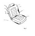
- Fig. 1shows a perspective view of a seat 1 for motor vehicles, which consists essentially of a seat structure 2 with seat cushion 3 and a movably connected thereto backrest 4 with backrest cushion 5.
- Seat cushion 3 and backrest cushion 5are covered with a cushion cover 6, which may have different materials. For example, materials from a textile structure or leather are customary, while material sections are sewn to form the covering.
- decorative seamsare provided to give the user an attractive look.
- the backrest 4 of the illustrated vehicle seat 1in this case comprises a central backrest region 7 for supporting the back of the user, as well as laterally arranged side cheek regions 8.
- the sectional view of the FIG. 5shows that the backrest cushion 5 is subdivided into a middle backrest cushion 5a, as well as the side walls surrounding poster elements 5b.
- the padding elementsare made of a foam material such as PU foam.
- Both the middle backrest region having the middle backrest pad 7, and the side cheeks 8 having the padding elements and the back 9 of the backrest 4are enveloped by a padding cover 6.
- the side cheek coveris formed from two material sections 6a, 6b, which are referred to below as the front side cheek reference section 6a, and the rear side cheek reference section 6b.
- Seamsare formed by stitching the reference portions 6a, 6b of the side cheek reference portions and stitching the front side cheek reference portion 6a to a center backrest cover portion 6c and stitching the rear side panel cover portion 6b to a rear seatback cover portion 6d.
- Airbag devices 11are well known and will not be described in detail here. Essentially, these consist of one Housing, a gas generator and a gas bag.
- the airbag housing 12comprises side walls, a rear wall and a cover 13, which has a U-shaped perforation and breaks upon deployment of the airbag and pivots about a hinge axis to the outside.
- the airbag housing 12is usually made of a plastic material.
- the backrest covercomprises a front side cheek reference section 6a and a rear side cheek reference section 6b, which are connected to each other via a vertical seam.
- the tear seam 14is formed.
- the beginning and the end of the tear seam 14are in the Fig. 4 characterized by the reference numerals A1 and A2.
- the tear seamtears open accordingly.
- a planar reinforcing material layer 15a, 15b lying between padding and reference sections 6a, 6bis attached on both sides, each with a first edge region.
- the reinforcing material layerintroduces the forces required for tearing into the tear seam 14 and forms the force lamination mentioned in the introduction to the description.
- the reinforcing material layer 15a, 15bis made of a material which has a lower elongation and a higher tensile strength than the cover.
- the reinforcing material layers 15a, 15bare fastened to the backrest via a number of fixing means 18 at their edge region 17a, 17b opposite the first edge region.
- the fixing means 18are preferably completely or partially embedded in the padding. In the illustrated embodiment of the invention, these fixation means 18 are wires embedded in the padding for tie-down (guy wires).
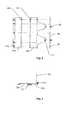
- the FIG. 2shows the reinforcing material layers 15a, 15b and the fixing means 18 in detail.
- the reinforcing material layersare shown in the unsewn state.
- the arranged at the tear seam in the sewn statefirst edge regions of the reinforcing material layers are spaced apart with their outer edges.
- the seamsare drawn in a broken line.
- the reinforcing material layer 15ais designed substantially as a rectangular piece of material.
- the first edge region opposite second edge region 17ais connected to a retaining strip (retainer).
- the reinforcing material layer 15bhas a rectangular piece of material and two tapered hanger tabs.
- the edge regions of the Ein Strukturlaschenthereby form the second edge region.
- Retaining strips (retainers) with one eyeletare also made on the edge.
- On the right side of the drawingformed as a cushion wire fixing means is shown.
- the fixing meansin this case has straight sections and intervening sections with protruding eyelets. From the illustration it can be seen that the sections with eyelets are arranged opposite the retaining strips of the tapered hanging tabs of the reinforcing material layer 15b. In the installed state, the suspension straps are connected via rigid traction means 19, for example rings with the sections with eyelets. The retaining strip of the reinforcing material layer 15a is also connected via rigid traction means 19 with the straight portions of the fixing means. This will, as you can see from the presentation of FIG. 5 can see a side bolster with built-in airbag device encompassing closed bag-shaped fixation achieved.
- Fig. 3shows the planar superimposed and stitched arrangement of the side cheek reference portions 6a, 6b with the reinforcing material layers 15a, 15b and the interface between the rear side cheek reference section with a rear seat back reference portion 6d.
- the retaining strips of the reinforcing material layersare not yet connected in the illustration with the fixing means.
Landscapes
- Engineering & Computer Science (AREA)
- Mechanical Engineering (AREA)
- Aviation & Aerospace Engineering (AREA)
- Transportation (AREA)
- Air Bags (AREA)
Abstract
Description
Translated fromGermanDie vorliegende Erfindung betrifft einen Sitz für Kraftfahrzeuge.The present invention relates to a seat for motor vehicles.
Die Anforderungen an die passive und aktive Sicherheit eines Kraftfahrzeuges steigen stetig. Es ist mittlerweile üblich eine Vielzahl von Airbageinrichtungen im Kraftfahrzeug vorzusehen. Neben den Fahrer- und Beifahrerairbags werden unter anderem auch Seitenairbags verbaut.The requirements for the passive and active safety of a motor vehicle are rising steadily. It is now common to provide a plurality of airbag devices in the motor vehicle. In addition to the driver and passenger airbags, side airbags are also installed.
Diese sollen bei einem Seitencrash den Fahrer bzw. Beifahrer zusätzlich vor größeren Verletzungen schützen und sind häufig in einem Seitenbereich eines Fahrzeugsitzes angeordnet. Ein im Fahrzeugsitz bzw. dem Seitenbereich des Fahrzeugsitzes angeordneter Airbag entfaltet sich dabei durch eine sogenannte Reißnaht die im Sitzbezug ausgeführt ist. Problematisch bei einer derartigen Ausführung ist allerdings, dass das Aufreißen d.h. die Aufreißgeschwindigkeit und auch die Optik des Bezuges des Fahrzeugsitzes und der Reißnaht abhängig vom Bezugsmaterial, des Nahtmaterials und der Art der Nähte abhängt. Wie bereits erläutert, müssen aus Sicherheitsaspekten das Öffnen der Reißnaht und das Entfalten der Airbageinrichtung vorhersehbar sein. Eine Unabhängigkeit vom verwendeten Bezug soll ebenfalls sichergestellt werden. Um dies zu erzielen werden die Sitzbezüge mit sogenannten Entfaltungs-/Positionierhilfen aus einem weniger dehnbarem Material ausgestattet.These are to protect the driver or passenger in a side crash additionally from major injuries and are often located in a side region of a vehicle seat. A arranged in the vehicle seat or the side region of the vehicle seat airbag unfolds by a so-called tear seam is executed in the seat cover. However, a problem with such an embodiment is that the tearing, i. the tearing speed and also the appearance of the cover of the vehicle seat and the tear seam depends on the cover material, the suture and the type of seams. As already explained, for safety reasons, the opening of the tear seam and the deployment of the airbag device must be predictable. Independence from the reference used should also be ensured. To achieve this, the seat covers are equipped with so-called unfolding / positioning aids made of a less stretchable material.
Der vorliegenden Erfindung liegt die Aufgabe zugrunde, einen Sitz mit einer in einem Aufnahmeraum des Seitenbereichs angeordneten Airbageinrichtung derart weiterzubilden, dass eine einfache und kostengünstige Fertigung der Vorrichtung und Montage der Bauteile möglich ist, wobei ein funktionssicheres, vorhersehbares Aufreißen der Reißnaht bei unterschiedlichen Sitzbezugsmaterialien sichergestellt ist.The present invention has for its object to provide a seat with a arranged in a receiving space of the side region airbag device such that a simple and cost-effective production of the device and assembly of the components is possible, with a functionally reliable, predictable tearing of the tear seam is ensured at different seat cover materials ,
Diese Aufgabe löst die vorliegende Erfindung durch die im Patentanspruch 1 angegebenen Merkmale.This object is achieved by the present invention by the features specified in
Durch diese erfindungsgemäße Ausgestaltung sind die Verstärkungsmateriallagen an ihrem der Nahtlinie gegenüberliegenden Randbereich über Fixierungsmittel an der Rückenlehne befestigt und bilden eine das Seitenwangenpolster mit Airbag umgreifende geschlossene sackförmige Fixierung. Durch die Verwendung der gleichen Fixierungsmittel zur Befestigung der Verstärkungsmateriallagen an den der Aufreißnaht gegenüberliegenden Randbereichen ist eine einfache und kostengünstige Fertigung der Bauteile möglich.By means of this embodiment according to the invention, the reinforcing material layers are fastened to the backrest at their edge region opposite the seam line by means of fixing means and form a side cheek cushion with airbag Closed bag-shaped fixation. By using the same fixing means for fastening the reinforcing material layers to the tear seam opposite edge regions a simple and cost-effective production of the components is possible.
Bei Kraftfahrzeugsitzen wird der das Polster überspannende Sitzbezug über Stoff-Fahnen, Drahtbügel oder andere geeignete Mittel in eine Anzahl von Vertiefungen eines Polsters gezogen. Derartige Abspannvorrichtungen sind bekannt und umfassen vorteilhafterweise im Polstereingeschäumte Abspanndrähte, die zur Festlegung der vorgenannten Stoff-Fahnen, Drahtbügel oder anderer Befestigungsmittel dient. Die Verstärkungsmateriallagen können erfindungsgemäß einfach, kostengünstig und schnell an einem dem ersten Randbereich gegenüberliegenden zweiten Randbereich über eine Anzahl von Fixierungsmitteln, die mit der Polsterung zusammenhängen oder verbunden sind, an der Rückenlehne befestigt werden. Hierbei können insbesondere die für die Bezugsabspannung dienenden Abspanndrähte genutzt werden. Somit entfällt die Anordnung von separaten Fixierungsmitteln für die Festlegung der zweiten Randbereiche der Verstärkungsmateriallage.In motor vehicle seats, the upholstery spanning the seat cover is pulled over fabric tabs, wire hangers or other suitable means into a number of indentations of a pad. Such guying devices are known and advantageously comprise in the padded guying wires, which serves for fixing the aforementioned fabric flags, wire hanger or other fastening means. According to the invention, the reinforcing material layers can be attached to the backrest in a simple, cost-effective and quick manner at a second edge region opposite the first edge region via a number of fixing means which are connected or connected to the upholstery. In this case, in particular serving for the Bezugsabspannung guy wires can be used. Thus, eliminating the arrangement of separate fixing means for the determination of the second edge regions of the reinforcing material layer.
Weitere vorteilhafte Ausgestaltungen und Weiterbildungen des erfindungsgemäßen Sitzes für Kraftfahrzeuge ergeben sich aus den jeweiligen Unteransprüchen.Further advantageous embodiments and further developments of the seat according to the invention for motor vehicles emerge from the respective subclaims.
Eine bevorzugte Ausführungsform der vorliegenden Erfindung wird nachfolgend beispielshalber beschrieben, wobei veranschaulichend auf die beigefügten Zeichnungen Bezug genommen wird.A preferred embodiment of the present invention will now be described by way of example, with reference to the accompanying drawings by way of illustrative example.
Darin zeigen:
- Fig. 1
- eine perspektivische Ansicht eines Fahrzeugsitzes,
- Fig. 2
- die Verstärkungsmateriallage mit Fixierungsmittel,
- Fig. 3
- in schematischer Ansicht die Einzelteile des Bezugs im Bereich der Gassackeinrichtung mit Verstärkungsmateriallage und die Nahtstellen,
- Fig. 4
- eine perspektivische Ansicht des Seitenbereichs eines Fahrzeugsitzes mit integrierter Gassackeinrichtung; und
- Fig. 5
- einen Schnitt durch den in
Fig. 4 dargestellten Seitenbereich.
- Fig. 1
- a perspective view of a vehicle seat,
- Fig. 2
- the reinforcement material layer with fixative,
- Fig. 3
- a schematic view of the individual parts of the cover in the region of the gas bag device with reinforcing material layer and the seams,
- Fig. 4
- a perspective view of the side portion of a vehicle seat with integrated airbag device; and
- Fig. 5
- a section through the in
Fig. 4 displayed side area.
Die Rückenlehne 4 des dargestellten Fahrzeugsitzes 1 umfasst dabei einen mittleren Rückenlehnenbereich 7 zum Stützen des Rücken des Benutzers, sowie seitlich angeordnete Seitenwangenbereiche 8 auf. Die Schnittdarstellung der
Wie es aus der Darstellung der
Wie es aus der Darstellung der
Die Verstärkungsmateriallagen 15a, 15b sind an ihrem dem ersten Randbereich gegenüberliegenden Randbereich 17a, 17b über eine Anzahl von Fixierungsmitteln 18 an der Rückenlehne befestigt. Die Fixierungsmittel 18 sind vorzugsweise ganz oder teilweise in die Polsterung eingebettet. In der dargestellten Ausführungsform der Erfindung sind diese Fixierungsmittel 18 Drähte, die zur Bezugsabspannung in der Polsterung eingebettet sind (Abspanndrähte).The reinforcing
Die
Das Fixierungsmittel weist hierbei gerade verlaufende Abschnitte sowie dazwischen liegende Abschnitte mit herausstehenden Ösen auf. Aus der Darstellung kann man ersehen, dass die Abschnitte mit Ösen den Halteleisten der spitz zulaufenden Einhängelaschen der Verstärkungsmateriallage 15b gegenüberliegend angeordnet sind. Im verbauten Zustand werden die Einhängelaschen über starre Zugmittel 19, beispielsweise Ringe mit den Abschnitten mit Ösen verbunden. Die Halteleiste der Verstärkungsmateriallage 15a wird ebenfalls über starre Zugmittel 19 mit den geraden Abschnitten des Fixierungsmittels verbunden. Hierdurch wird, wie man es aus der Darstellung der
Claims (6)
Translated fromGermanApplications Claiming Priority (1)
| Application Number | Priority Date | Filing Date | Title |
|---|---|---|---|
| DE102011117835.3ADE102011117835B4 (en) | 2011-11-08 | 2011-11-08 | Seat for a motor vehicle |
Publications (2)
| Publication Number | Publication Date |
|---|---|
| EP2591954A1true EP2591954A1 (en) | 2013-05-15 |
| EP2591954B1 EP2591954B1 (en) | 2016-01-06 |
Family
ID=46940362
Family Applications (1)
| Application Number | Title | Priority Date | Filing Date |
|---|---|---|---|
| EP12185437.6AActiveEP2591954B1 (en) | 2011-11-08 | 2012-09-21 | Seat for motor vehicles |
Country Status (2)
| Country | Link |
|---|---|
| EP (1) | EP2591954B1 (en) |
| DE (1) | DE102011117835B4 (en) |
Families Citing this family (2)
| Publication number | Priority date | Publication date | Assignee | Title |
|---|---|---|---|---|
| DE102016200998A1 (en) | 2015-01-26 | 2016-07-28 | Ford Global Technologies, Llc | Seat arrangement with side airbag |
| DE102020212172B4 (en)* | 2019-10-02 | 2025-08-14 | Magna Seating (Germany) Gmbh | Vehicle seat with side airbag, and method for mounting a vehicle seat with a side airbag |
Citations (6)
| Publication number | Priority date | Publication date | Assignee | Title |
|---|---|---|---|---|
| DE19848905A1 (en)* | 1997-10-31 | 1999-05-06 | Ts Tech Co | Car seat with side air bag on one side of back rest frame |
| US5927749A (en)* | 1996-11-12 | 1999-07-27 | Magna Lomason Corporation | Side air bag directional guide system |
| US20070145727A1 (en)* | 2005-12-28 | 2007-06-28 | Mazda Motor Corporation | Seat with airbag unit for vehicle |
| DE102007054162A1 (en)* | 2006-11-14 | 2008-07-03 | W.E.T. Automotive Systems Ag | Unbending device for filing support of interior fixture i.e. vehicle seat, into unbending ditch, has reinforcement device distributing tensile forces of tensile transfer device uniformly along support |
| US20100140905A1 (en)* | 2008-12-04 | 2010-06-10 | Hyundai Motor Company | Seat Cover for Vehicle and Seat Having the Same |
| DE102009044759A1 (en)* | 2009-05-21 | 2010-12-30 | Hyundai Motor Co. | Vehicle seat with side airbag |
Family Cites Families (3)
| Publication number | Priority date | Publication date | Assignee | Title |
|---|---|---|---|---|
| US5678853A (en)* | 1996-06-26 | 1997-10-21 | Morton International, Inc. | Airbag module with deployment chute |
| US5967603A (en)* | 1997-09-25 | 1999-10-19 | Johnson Controls Technology Company | Seat mounted airbag with deployment force concentrator |
| US5938232A (en)* | 1997-10-24 | 1999-08-17 | Breed Automotive Technology, Inc. | Force directing air bag deployment pocket |
- 2011
- 2011-11-08DEDE102011117835.3Apatent/DE102011117835B4/ennot_activeExpired - Fee Related
- 2012
- 2012-09-21EPEP12185437.6Apatent/EP2591954B1/enactiveActive
Patent Citations (6)
| Publication number | Priority date | Publication date | Assignee | Title |
|---|---|---|---|---|
| US5927749A (en)* | 1996-11-12 | 1999-07-27 | Magna Lomason Corporation | Side air bag directional guide system |
| DE19848905A1 (en)* | 1997-10-31 | 1999-05-06 | Ts Tech Co | Car seat with side air bag on one side of back rest frame |
| US20070145727A1 (en)* | 2005-12-28 | 2007-06-28 | Mazda Motor Corporation | Seat with airbag unit for vehicle |
| DE102007054162A1 (en)* | 2006-11-14 | 2008-07-03 | W.E.T. Automotive Systems Ag | Unbending device for filing support of interior fixture i.e. vehicle seat, into unbending ditch, has reinforcement device distributing tensile forces of tensile transfer device uniformly along support |
| US20100140905A1 (en)* | 2008-12-04 | 2010-06-10 | Hyundai Motor Company | Seat Cover for Vehicle and Seat Having the Same |
| DE102009044759A1 (en)* | 2009-05-21 | 2010-12-30 | Hyundai Motor Co. | Vehicle seat with side airbag |
Also Published As
| Publication number | Publication date |
|---|---|
| DE102011117835B4 (en) | 2015-10-08 |
| DE102011117835A1 (en) | 2013-05-08 |
| EP2591954B1 (en) | 2016-01-06 |
Similar Documents
| Publication | Publication Date | Title |
|---|---|---|
| DE102005002200B4 (en) | The air bag deployment arrangement | |
| DE69809194T2 (en) | SIDE AIR BAG BUILT INTO A SEAT WITH UNFOLDING FORCE CONCENTRATION DEVICE | |
| DE102013205066B4 (en) | Vehicle seat assembly with a backplane module | |
| DE69832718T2 (en) | POWERFUL AIRBAG DEFENSE BAG | |
| DE19950702B4 (en) | Automotive seat | |
| DE102005057437B4 (en) | Side airbag system in a vehicle seat | |
| DE102007030372A1 (en) | Soft-Cover side airbag module with fleece-reinforced backrest foam part | |
| DE102007011823A1 (en) | Vehicle seat assembly with power amplification device for tearing an airbag seam | |
| DE102013210069A1 (en) | VEHICLE SEAT | |
| DE102008049505B4 (en) | Airbag arrangement for a vehicle seat and vehicle seat with the airbag assembly | |
| DE102004051663B4 (en) | Foam body for producing a vehicle seat with airbag module | |
| DE112015003867T5 (en) | Folding pattern for an inflatable safety belt | |
| DE112015003910T5 (en) | Inflatable safety belt with a connected gas supply hose | |
| DE102005057497B4 (en) | Side airbag system in a vehicle seat | |
| EP2942242B1 (en) | Head airbag system for a vehicle and vehicle with a head airbag system | |
| EP2591954B1 (en) | Seat for motor vehicles | |
| DE102005057501A1 (en) | Vehicle seat assembly | |
| DE102004042039B4 (en) | Backrest for a vehicle seat | |
| WO2019228735A1 (en) | Motor vehicle | |
| DE10254723A1 (en) | Passenger protective device for a motor in form of side airbags housed in motor vehicle seats has strengthened ejection seam | |
| EP3894272B1 (en) | Vehicle seat | |
| DE102020105293B4 (en) | Impact cushion device for a motor vehicle | |
| WO2021198056A1 (en) | Airbag module, in particular side-airbag module, comprising a flexible deflection and protection belt, and arrangement of same | |
| DE102007061879A1 (en) | Seat for vehicle i.e. motor vehicle such as land vehicle with internal combustion engine, has belt connected to airbag module in area and to cover in another area, where belt is connected with cover between airbag module and opening line | |
| DE102008023931B4 (en) | vehicle seat |
Legal Events
| Date | Code | Title | Description |
|---|---|---|---|
| PUAI | Public reference made under article 153(3) epc to a published international application that has entered the european phase | Free format text:ORIGINAL CODE: 0009012 | |
| AK | Designated contracting states | Kind code of ref document:A1 Designated state(s):AL AT BE BG CH CY CZ DE DK EE ES FI FR GB GR HR HU IE IS IT LI LT LU LV MC MK MT NL NO PL PT RO RS SE SI SK SM TR | |
| AX | Request for extension of the european patent | Extension state:BA ME | |
| 17P | Request for examination filed | Effective date:20130603 | |
| RBV | Designated contracting states (corrected) | Designated state(s):AL AT BE BG CH CY CZ DE DK EE ES FI FR GB GR HR HU IE IS IT LI LT LU LV MC MK MT NL NO PL PT RO RS SE SI SK SM TR | |
| 17Q | First examination report despatched | Effective date:20141029 | |
| GRAP | Despatch of communication of intention to grant a patent | Free format text:ORIGINAL CODE: EPIDOSNIGR1 | |
| INTG | Intention to grant announced | Effective date:20150914 | |
| GRAS | Grant fee paid | Free format text:ORIGINAL CODE: EPIDOSNIGR3 | |
| GRAA | (expected) grant | Free format text:ORIGINAL CODE: 0009210 | |
| AK | Designated contracting states | Kind code of ref document:B1 Designated state(s):AL AT BE BG CH CY CZ DE DK EE ES FI FR GB GR HR HU IE IS IT LI LT LU LV MC MK MT NL NO PL PT RO RS SE SI SK SM TR | |
| REG | Reference to a national code | Ref country code:GB Ref legal event code:FG4D Free format text:NOT ENGLISH | |
| REG | Reference to a national code | Ref country code:CH Ref legal event code:EP | |
| REG | Reference to a national code | Ref country code:IE Ref legal event code:FG4D Free format text:LANGUAGE OF EP DOCUMENT: GERMAN | |
| REG | Reference to a national code | Ref country code:AT Ref legal event code:REF Ref document number:768575 Country of ref document:AT Kind code of ref document:T Effective date:20160215 | |
| REG | Reference to a national code | Ref country code:DE Ref legal event code:R096 Ref document number:502012005651 Country of ref document:DE | |
| REG | Reference to a national code | Ref country code:LT Ref legal event code:MG4D | |
| REG | Reference to a national code | Ref country code:NL Ref legal event code:MP Effective date:20160106 | |
| PG25 | Lapsed in a contracting state [announced via postgrant information from national office to epo] | Ref country code:NL Free format text:LAPSE BECAUSE OF FAILURE TO SUBMIT A TRANSLATION OF THE DESCRIPTION OR TO PAY THE FEE WITHIN THE PRESCRIBED TIME-LIMIT Effective date:20160106 | |
| PG25 | Lapsed in a contracting state [announced via postgrant information from national office to epo] | Ref country code:FI Free format text:LAPSE BECAUSE OF FAILURE TO SUBMIT A TRANSLATION OF THE DESCRIPTION OR TO PAY THE FEE WITHIN THE PRESCRIBED TIME-LIMIT Effective date:20160106 Ref country code:ES Free format text:LAPSE BECAUSE OF FAILURE TO SUBMIT A TRANSLATION OF THE DESCRIPTION OR TO PAY THE FEE WITHIN THE PRESCRIBED TIME-LIMIT Effective date:20160106 Ref country code:GR Free format text:LAPSE BECAUSE OF FAILURE TO SUBMIT A TRANSLATION OF THE DESCRIPTION OR TO PAY THE FEE WITHIN THE PRESCRIBED TIME-LIMIT Effective date:20160407 Ref country code:HR Free format text:LAPSE BECAUSE OF FAILURE TO SUBMIT A TRANSLATION OF THE DESCRIPTION OR TO PAY THE FEE WITHIN THE PRESCRIBED TIME-LIMIT Effective date:20160106 Ref country code:IT Free format text:LAPSE BECAUSE OF FAILURE TO SUBMIT A TRANSLATION OF THE DESCRIPTION OR TO PAY THE FEE WITHIN THE PRESCRIBED TIME-LIMIT Effective date:20160106 Ref country code:NO Free format text:LAPSE BECAUSE OF FAILURE TO SUBMIT A TRANSLATION OF THE DESCRIPTION OR TO PAY THE FEE WITHIN THE PRESCRIBED TIME-LIMIT Effective date:20160406 | |
| PG25 | Lapsed in a contracting state [announced via postgrant information from national office to epo] | Ref country code:PL Free format text:LAPSE BECAUSE OF FAILURE TO SUBMIT A TRANSLATION OF THE DESCRIPTION OR TO PAY THE FEE WITHIN THE PRESCRIBED TIME-LIMIT Effective date:20160106 Ref country code:IS Free format text:LAPSE BECAUSE OF FAILURE TO SUBMIT A TRANSLATION OF THE DESCRIPTION OR TO PAY THE FEE WITHIN THE PRESCRIBED TIME-LIMIT Effective date:20160506 Ref country code:SE Free format text:LAPSE BECAUSE OF FAILURE TO SUBMIT A TRANSLATION OF THE DESCRIPTION OR TO PAY THE FEE WITHIN THE PRESCRIBED TIME-LIMIT Effective date:20160106 Ref country code:RS Free format text:LAPSE BECAUSE OF FAILURE TO SUBMIT A TRANSLATION OF THE DESCRIPTION OR TO PAY THE FEE WITHIN THE PRESCRIBED TIME-LIMIT Effective date:20160106 Ref country code:PT Free format text:LAPSE BECAUSE OF FAILURE TO SUBMIT A TRANSLATION OF THE DESCRIPTION OR TO PAY THE FEE WITHIN THE PRESCRIBED TIME-LIMIT Effective date:20160506 Ref country code:LT Free format text:LAPSE BECAUSE OF FAILURE TO SUBMIT A TRANSLATION OF THE DESCRIPTION OR TO PAY THE FEE WITHIN THE PRESCRIBED TIME-LIMIT Effective date:20160106 Ref country code:LV Free format text:LAPSE BECAUSE OF FAILURE TO SUBMIT A TRANSLATION OF THE DESCRIPTION OR TO PAY THE FEE WITHIN THE PRESCRIBED TIME-LIMIT Effective date:20160106 | |
| REG | Reference to a national code | Ref country code:FR Ref legal event code:PLFP Year of fee payment:5 | |
| REG | Reference to a national code | Ref country code:DE Ref legal event code:R097 Ref document number:502012005651 Country of ref document:DE | |
| PG25 | Lapsed in a contracting state [announced via postgrant information from national office to epo] | Ref country code:DK Free format text:LAPSE BECAUSE OF FAILURE TO SUBMIT A TRANSLATION OF THE DESCRIPTION OR TO PAY THE FEE WITHIN THE PRESCRIBED TIME-LIMIT Effective date:20160106 Ref country code:EE Free format text:LAPSE BECAUSE OF FAILURE TO SUBMIT A TRANSLATION OF THE DESCRIPTION OR TO PAY THE FEE WITHIN THE PRESCRIBED TIME-LIMIT Effective date:20160106 | |
| PLBE | No opposition filed within time limit | Free format text:ORIGINAL CODE: 0009261 | |
| STAA | Information on the status of an ep patent application or granted ep patent | Free format text:STATUS: NO OPPOSITION FILED WITHIN TIME LIMIT | |
| PG25 | Lapsed in a contracting state [announced via postgrant information from national office to epo] | Ref country code:SK Free format text:LAPSE BECAUSE OF FAILURE TO SUBMIT A TRANSLATION OF THE DESCRIPTION OR TO PAY THE FEE WITHIN THE PRESCRIBED TIME-LIMIT Effective date:20160106 Ref country code:SM Free format text:LAPSE BECAUSE OF FAILURE TO SUBMIT A TRANSLATION OF THE DESCRIPTION OR TO PAY THE FEE WITHIN THE PRESCRIBED TIME-LIMIT Effective date:20160106 Ref country code:CZ Free format text:LAPSE BECAUSE OF FAILURE TO SUBMIT A TRANSLATION OF THE DESCRIPTION OR TO PAY THE FEE WITHIN THE PRESCRIBED TIME-LIMIT Effective date:20160106 Ref country code:RO Free format text:LAPSE BECAUSE OF FAILURE TO SUBMIT A TRANSLATION OF THE DESCRIPTION OR TO PAY THE FEE WITHIN THE PRESCRIBED TIME-LIMIT Effective date:20160106 | |
| 26N | No opposition filed | Effective date:20161007 | |
| PG25 | Lapsed in a contracting state [announced via postgrant information from national office to epo] | Ref country code:BG Free format text:LAPSE BECAUSE OF FAILURE TO SUBMIT A TRANSLATION OF THE DESCRIPTION OR TO PAY THE FEE WITHIN THE PRESCRIBED TIME-LIMIT Effective date:20160406 Ref country code:BE Free format text:LAPSE BECAUSE OF NON-PAYMENT OF DUE FEES Effective date:20160930 Ref country code:SI Free format text:LAPSE BECAUSE OF FAILURE TO SUBMIT A TRANSLATION OF THE DESCRIPTION OR TO PAY THE FEE WITHIN THE PRESCRIBED TIME-LIMIT Effective date:20160106 | |
| PG25 | Lapsed in a contracting state [announced via postgrant information from national office to epo] | Ref country code:MC Free format text:LAPSE BECAUSE OF FAILURE TO SUBMIT A TRANSLATION OF THE DESCRIPTION OR TO PAY THE FEE WITHIN THE PRESCRIBED TIME-LIMIT Effective date:20160106 | |
| REG | Reference to a national code | Ref country code:CH Ref legal event code:PL | |
| REG | Reference to a national code | Ref country code:IE Ref legal event code:MM4A | |
| PG25 | Lapsed in a contracting state [announced via postgrant information from national office to epo] | Ref country code:LI Free format text:LAPSE BECAUSE OF NON-PAYMENT OF DUE FEES Effective date:20160930 Ref country code:CH Free format text:LAPSE BECAUSE OF NON-PAYMENT OF DUE FEES Effective date:20160930 Ref country code:IE Free format text:LAPSE BECAUSE OF NON-PAYMENT OF DUE FEES Effective date:20160921 | |
| PG25 | Lapsed in a contracting state [announced via postgrant information from national office to epo] | Ref country code:LU Free format text:LAPSE BECAUSE OF NON-PAYMENT OF DUE FEES Effective date:20160921 | |
| REG | Reference to a national code | Ref country code:FR Ref legal event code:PLFP Year of fee payment:6 | |
| REG | Reference to a national code | Ref country code:BE Ref legal event code:MM Effective date:20160930 | |
| PG25 | Lapsed in a contracting state [announced via postgrant information from national office to epo] | Ref country code:CY Free format text:LAPSE BECAUSE OF FAILURE TO SUBMIT A TRANSLATION OF THE DESCRIPTION OR TO PAY THE FEE WITHIN THE PRESCRIBED TIME-LIMIT Effective date:20160106 Ref country code:HU Free format text:LAPSE BECAUSE OF FAILURE TO SUBMIT A TRANSLATION OF THE DESCRIPTION OR TO PAY THE FEE WITHIN THE PRESCRIBED TIME-LIMIT; INVALID AB INITIO Effective date:20120921 | |
| PG25 | Lapsed in a contracting state [announced via postgrant information from national office to epo] | Ref country code:MK Free format text:LAPSE BECAUSE OF FAILURE TO SUBMIT A TRANSLATION OF THE DESCRIPTION OR TO PAY THE FEE WITHIN THE PRESCRIBED TIME-LIMIT Effective date:20160106 Ref country code:MT Free format text:LAPSE BECAUSE OF FAILURE TO SUBMIT A TRANSLATION OF THE DESCRIPTION OR TO PAY THE FEE WITHIN THE PRESCRIBED TIME-LIMIT Effective date:20160106 | |
| REG | Reference to a national code | Ref country code:FR Ref legal event code:PLFP Year of fee payment:7 | |
| PG25 | Lapsed in a contracting state [announced via postgrant information from national office to epo] | Ref country code:AL Free format text:LAPSE BECAUSE OF FAILURE TO SUBMIT A TRANSLATION OF THE DESCRIPTION OR TO PAY THE FEE WITHIN THE PRESCRIBED TIME-LIMIT Effective date:20160106 | |
| REG | Reference to a national code | Ref country code:AT Ref legal event code:MM01 Ref document number:768575 Country of ref document:AT Kind code of ref document:T Effective date:20170921 | |
| PG25 | Lapsed in a contracting state [announced via postgrant information from national office to epo] | Ref country code:AT Free format text:LAPSE BECAUSE OF NON-PAYMENT OF DUE FEES Effective date:20170921 | |
| PGFP | Annual fee paid to national office [announced via postgrant information from national office to epo] | Ref country code:FR Payment date:20210921 Year of fee payment:10 | |
| PGFP | Annual fee paid to national office [announced via postgrant information from national office to epo] | Ref country code:GB Payment date:20210920 Year of fee payment:10 | |
| GBPC | Gb: european patent ceased through non-payment of renewal fee | Effective date:20220921 | |
| PG25 | Lapsed in a contracting state [announced via postgrant information from national office to epo] | Ref country code:FR Free format text:LAPSE BECAUSE OF NON-PAYMENT OF DUE FEES Effective date:20220930 | |
| PG25 | Lapsed in a contracting state [announced via postgrant information from national office to epo] | Ref country code:GB Free format text:LAPSE BECAUSE OF NON-PAYMENT OF DUE FEES Effective date:20220921 | |
| PGFP | Annual fee paid to national office [announced via postgrant information from national office to epo] | Ref country code:DE Payment date:20240918 Year of fee payment:13 | |
| PGFP | Annual fee paid to national office [announced via postgrant information from national office to epo] | Ref country code:TR Payment date:20240913 Year of fee payment:13 | |
| REG | Reference to a national code | Ref country code:DE Ref legal event code:R082 Ref document number:502012005651 Country of ref document:DE Representative=s name:EULER, MATTHIAS, DR., DE |