EP2591369B1 - Automated system for selectively processing a sample. - Google Patents
Automated system for selectively processing a sample.Download PDFInfo
- Publication number
- EP2591369B1 EP2591369B1EP11734187.5AEP11734187AEP2591369B1EP 2591369 B1EP2591369 B1EP 2591369B1EP 11734187 AEP11734187 AEP 11734187AEP 2591369 B1EP2591369 B1EP 2591369B1
- Authority
- EP
- European Patent Office
- Prior art keywords
- cartridge
- sample
- cartridges
- reagents
- assays
- Prior art date
- Legal status (The legal status is an assumption and is not a legal conclusion. Google has not performed a legal analysis and makes no representation as to the accuracy of the status listed.)
- Active
Links
Images


Classifications
- B—PERFORMING OPERATIONS; TRANSPORTING
- B01—PHYSICAL OR CHEMICAL PROCESSES OR APPARATUS IN GENERAL
- B01L—CHEMICAL OR PHYSICAL LABORATORY APPARATUS FOR GENERAL USE
- B01L3/00—Containers or dishes for laboratory use, e.g. laboratory glassware; Droppers
- B01L3/50—Containers for the purpose of retaining a material to be analysed, e.g. test tubes
- B01L3/505—Containers for the purpose of retaining a material to be analysed, e.g. test tubes flexible containers not provided for above
- G—PHYSICS
- G01—MEASURING; TESTING
- G01N—INVESTIGATING OR ANALYSING MATERIALS BY DETERMINING THEIR CHEMICAL OR PHYSICAL PROPERTIES
- G01N35/00—Automatic analysis not limited to methods or materials provided for in any single one of groups G01N1/00 - G01N33/00; Handling materials therefor
- G01N35/00029—Automatic analysis not limited to methods or materials provided for in any single one of groups G01N1/00 - G01N33/00; Handling materials therefor provided with flat sample substrates, e.g. slides
- G01N2035/00099—Characterised by type of test elements
- G01N2035/00148—Test cards, e.g. Biomerieux or McDonnel multiwell test cards
- G—PHYSICS
- G01—MEASURING; TESTING
- G01N—INVESTIGATING OR ANALYSING MATERIALS BY DETERMINING THEIR CHEMICAL OR PHYSICAL PROPERTIES
- G01N35/00—Automatic analysis not limited to methods or materials provided for in any single one of groups G01N1/00 - G01N33/00; Handling materials therefor
- G01N35/02—Automatic analysis not limited to methods or materials provided for in any single one of groups G01N1/00 - G01N33/00; Handling materials therefor using a plurality of sample containers moved by a conveyor system past one or more treatment or analysis stations
- G01N35/04—Details of the conveyor system
- G01N2035/0401—Sample carriers, cuvettes or reaction vessels
- G01N2035/0429—Sample carriers adapted for special purposes
- G01N2035/0436—Sample carriers adapted for special purposes with pre-packaged reagents, i.e. test-packs
- G—PHYSICS
- G01—MEASURING; TESTING
- G01N—INVESTIGATING OR ANALYSING MATERIALS BY DETERMINING THEIR CHEMICAL OR PHYSICAL PROPERTIES
- G01N21/00—Investigating or analysing materials by the use of optical means, i.e. using sub-millimetre waves, infrared, visible or ultraviolet light
- G01N21/17—Systems in which incident light is modified in accordance with the properties of the material investigated
- G01N21/55—Specular reflectivity
- G01N21/552—Attenuated total reflection
- G—PHYSICS
- G01—MEASURING; TESTING
- G01N—INVESTIGATING OR ANALYSING MATERIALS BY DETERMINING THEIR CHEMICAL OR PHYSICAL PROPERTIES
- G01N35/00—Automatic analysis not limited to methods or materials provided for in any single one of groups G01N1/00 - G01N33/00; Handling materials therefor
- G01N35/00009—Automatic analysis not limited to methods or materials provided for in any single one of groups G01N1/00 - G01N33/00; Handling materials therefor provided with a sample supporting tape, e.g. with absorbent zones
- G—PHYSICS
- G01—MEASURING; TESTING
- G01N—INVESTIGATING OR ANALYSING MATERIALS BY DETERMINING THEIR CHEMICAL OR PHYSICAL PROPERTIES
- G01N35/00—Automatic analysis not limited to methods or materials provided for in any single one of groups G01N1/00 - G01N33/00; Handling materials therefor
- G01N35/0098—Automatic analysis not limited to methods or materials provided for in any single one of groups G01N1/00 - G01N33/00; Handling materials therefor involving analyte bound to insoluble magnetic carrier, e.g. using magnetic separation
Definitions
- the inventionrelates to a system and a method for processing a sample according to a selected one of a plurality of assays, particularly for detecting selected target components in a biological sample.
- a biosensoris known in which target components labeled with magnetic beads are detected by frustrated total internal reflection (FTIR) at the sensing surface of a cartridge.
- FTIRfrustrated total internal reflection
- the described biosensoris particularly designed and suited for point-of-care applications, for example roadside drug tests.
- the WO2004/055522 A1discloses an analyzer in which a sample provided in a sample container is first transferred into a fluid cartridge and from there further into an analysis cartridge comprising reagents.
- the US2010/028985 A1discloses a reaction vessel with a substrate on which a sample is mixed with a typing reagent and then transferred to a plurality of probe arrangements.
- the US2010/159487A1discloses a cartridge with an integrated delivery pipette by which a sample may be taken up. The pipette is then attached to the cartridge and together with it, introduced in an apparatus for analysis.
- the US2009/065368A1discloses an elaborated cartridge comprising a sample inlet at which a sample can be applied. The sample is then transported through a fluidic system of the cartridge to a plurality of different components and stages, including conduits coated with dry reagents.
- the US2007/148052A1discloses a cartridge with a plurality of wells into which a sample and liquid reagent can separately be injected.
- the US 2006/120926 A1discloses a cartridge with a plurality of chambers wherein one chamber is filled with a sample before the cartridge is introduced into a measuring instrument.
- the US 2004/197233 A1discloses an analyzer in which is a sample is applied to a testing module which comprises reagents.
- the US 2009/155123 A1relates to a system for the execution of PCR on multiple samples of nucleotides.
- JP2009148735 and US2007/116600show other examples of prior art documents.
- US2009/035746shows also an example of a system for processing a sample liquid having a cartridge, using dry reagents and magnetic particles and an actuation device to actuate the magnetic particles.
- the inventionrelates to a system as defined by claim 1 for processing a sample according to a selected one of a plurality of assays, particularly immunoassays.
- the sampleis typically a biological fluid, for example saliva or blood.
- the assayscomprise the instructions how a sample at hand shall be processed in order to achieve a desired result, wherein the processing comprises any arbitrary steps, including the physical and/or chemical modification of the sample.
- the aim of the assaysis for example the detection of different target components in a sample, for example of proteins, small molecules, antibodies, DNA, or the like.
- the processing steps of the assayswill typically require the use of specific reagents.
- the systemcomprises the following components:
- the described systemhas the advantage that the cartridges comprise already reagents required for the assay to be performed and simultaneously provide the physical environment for the processing. This facilitates the demands of available space and reduces the handling steps that have to be done.
- a cartridgecomprises already all the reagents needed for a given assay, the introduction of the sample into the cartridge is the only handling step with materials the manipulator has to do.
- each cartridgecomprises, the reagents needed for one and only one assay
- at least one cartridgecontains the reagents for several assays, preferably for up to four assays.
- cartridgesare usually present in a given system in many identical copies, such that a plurality of the same or of different assays can be performed with the system.
- carrierusually represents a whole type, set, or category of components.
- the inventioncomprises a method as defined by claim 2 for processing a sample according to a selected one of a plurality of assays, said method comprising the following steps:
- the cartridgesare designed in such a way that they enable execution of a complete assay with a sample added to the cartridge without further liquid handling steps, i.e. without the addition and/or transfer of liquid materials (besides the sample itself).
- the cartridgeis designed such that a sample added to the cartridge reaches all the associated reagents without further handling steps.
- the reagents associated to the same assayare disposed in one and the same sample chamber of the cartridge.
- the systemis accommodated in a housing.
- the cartridgesare then stored inside the instrument, and it is not necessary to (manually) insert a cartridge with each test.
- the system and the methodare suited for a high-throughput environment. Preferably, they are adapted to perform more than 20 tests/hour, preferably more than 50 tests/hour, most preferably more than 150 tests/hour.
- the cartridges used in the system or methodhave preferably a foil-based design, i.e. they comprise at least one layer made from a flexible sheet (foil). Preferably, all the layers of the cartridge are made from foils.
- a waste reservoiris arranged in the reach of the manipulator. Materials can then readily be disposed of at the end of an assay. As the cartridges are typically disposable units, used cartridges can be discarded in the waste reservoir, too.
- All the reagents of all cartridgesare dry reagents. In this case the only liquid involved in an assay is the sample liquid itself; this significantly reduces the volume of (liquid) waste.
- the system or the methodcomprises a readout-device in which target components of a sample can be detected, wherein said sample is preferably provided to the readout-device in one of the cartridges.
- the detection of target componentsapplies optical, electrical, magnetic, acoustic, radioactive or any other suitable measurement principles.
- the readout-devicefor example comprises a light source for illuminating a sample in a cartridge and a light detector for measuring light emitted from the sample (particularly by an FTIR process).
- the system or the methodcomprises at least one actuation- device in which a sample comprised in a cartridge can be actuated, preferably by the action of electromagnetic fields and/or heat.
- the actuation-deviceparticularly comprises a magnetic field generator, for example a permanent magnet or an electromagnet.
- the inclusion of an actuation-deviceincreases considerably the menu of assays that can be executed. The number of possible assays can even more be increased if several different actuation-devices are comprised by the system. Moreover, it is possible to provide several identical copies of an actuation-device so that a plurality of assays can be done in parallel.
- the system or the methodcomprises at least one integrated actuation-and-readout device. This reduces the handling steps to be done by the manipulator, because a sample (in a cartridge) can be delivered in one step to both an actuation and detection process.
- the at least one of the above-mentioned readout-devices, actuation-devices, and/or actuation-and-readout devicesare optionally movable by the manipulator together with a cartridge. This allows to perform some actuation and/or detection even while a cartridge (with a sample) is transported.
- the actuation-devicecomprises a magnet
- the exertion of magnetic forces on a samplecan favorably be continued during the movement of a cartridge.
- the reagents of the cartridgescomprise for example binding sites that are specific for different target components which may be present in a sample.
- binding sitesshall denote reagents that are immobilized on a surface (of a cartridge) and that specifically bind to certain (usually labeled) target components, thus immobilizing these, too.
- the reagents of the cartridgescomprise label particles that selectively bind to one target component which may be present in a sample.
- label particleshall denote a particle (atom, molecule, complex, nanoparticle, microparticle etc.) that has some property (e.g. optical density, magnetic susceptibility, electrical charge, fluorescence, radioactivity, etc.) which can be detected, thus indirectly revealing the presence of the associated target component.
- Typical examples of label particlesare magnetic beads.
- the cartridges of the system and/or lots in which cartridges are supplied to the systemmay optionally be provided with automatically readable information carriers, comprising for example information about calibration parameters.
- automatically readable information carrierscomprising for example information about calibration parameters.
- At least one cartridgepreferably comprises a plurality of sample chambers in which different assays can be executed.
- multiple assayscan be run in parallel on the same disposable cartridge, reducing the cost per assay results.
- the cartridge that is used in the system or the method described abovepreferably has a sample chamber in which examinations can be made, particularly optical examinations.
- the whole cartridge or at least a part of the cartridgeis transparent, for example made from transparent plastic.
- the transparent part of the cartridgeis provided with suitable optical elements like prismatic or lens-like protrusions or embossings, gratings, polished surface areas etc.
- the cartridgeis adapted to allow the examination of a sample in the sample chamber by frustrated total internal reflection (FTIR) of light emitted into the cartridge.
- FTIRfrustrated total internal reflection
- a cartridgewhich may be used in the above system or method and in other applications, too.
- Such a cartridgecomprises the following components:
- the cartridgeis more readily accessible for filling it with a sample and/or with reagents, and the filling is achieved quasi instantaneously (instead of slowly as if the fluid has to move along channels).
- a lidis provided for closing the top side of the sample chamber, wherein the lid is designed such that it does not hamper the free accessibility of the sample chamber through the top side.
- the lidmay for example be removable or readily destructible if access is required.
- the lidmay optionally be attached to the cartridge, for example via a hinge, or it may be a separate (removable) component.
- a removable lidmay optionally be reused many times (particularly if has some elaborate design), even if the associated cartridges are discarded. For this reason, the scope of the present application also extends to the lid as an article of its own, independent of the cartridge it shall be used with.
- the lidmay for example comprise a magnet.
- a magnetis typically needed in assays using magnetic particles.
- Combining the functions of a lid and a magnethas the advantage that only one part is needed and that the magnet can come into close proximity to a sample in the sample chamber.
- such a lid with a magnetconstitutes a component that is reused as often as possible.
- the lidcomprises a slanted interior surface and an air vent, wherein said air vent is disposed at the highest position of the lid.
- the lidis realized by a pierceable foil.
- the foilmay for instance be applied to the sample chamber during the production of the cartridge. Piercing of the foil can for example be readily done with a pipette.
- reagentsmay optionally be attached to said lid. If the lid is separate from the cartridge, selection and addition of reagents can hence be achieved by adding the appropriate lid (with reagents) to a cartridge.
- the inventionfurther relates to the use of a system of the kind described above for molecular diagnostics, biological sample analysis, chemical sample analysis, food analysis, and/or forensic analysis, particularly in a high-throughput automated laboratory environment.
- Molecular diagnosticsmay for example be accomplished with the help of magnetic beads or fluorescent particles that are directly or indirectly attached to target molecules.
- Magnetic beadsBiosensors based on nanoparticle labels, particularly nanoparticles that can be actuated with electromagnetic fields
- the magnetic beadsare functionalized with antibodies that can bind a specific target molecule.
- the beadsare attracted to the sensor surface, where the number of bound beads is directly or inversely related to the amount of target molecules present in the sample.
- the beadscan then be detected using any technique that is more sensitive to beads that are close to the surface, e.g. frustrated total internal reflection (FTIR).
- FTIRfrustrated total internal reflection
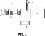
- Figure 1schematically illustrates such a laboratory system 1 for the execution of different assays with a sample 30 (typically plasma or serum).
- the systemis based on the so-called random-access concept and comprises a manipulator 40, which is controlled by a computer with appropriate software (not shown).
- the manipulator 40can take a sample to be investigated and transfer it to an open reaction vessel 10.
- the robothas access to a supply 20 of different wet reagents.
- the robotcan take the required reagents one by one from this supply 20 and add them to the reaction vessel 10.
- the reaction vessel 10is transferred to a detection- device (not shown) to quantify the outcome of the assay.
- a solution for this problemis based on the use of pre-loaded cartridges that already contain the reagents required for a specific test. When all reagents required to run an assay are contained in the disposable cartridge, many of the robotized sampling steps can be removed, thus significantly reducing the cost of the instrument. The only liquid handling step required would be to transfer the sample onto the disposable cartridge, minimizing the amount of robotics required.
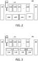
- FIG. 2illustrates a first particular embodiment of the above solution.
- This embodimentcomprises an instrument or system 100 for selectively performing one of a plurality of different possible assays.
- the systemis characterized in that it comprises a supply 110 with a plurality of (disposable) cartridges 111a, ... 111d.
- the cartridges 111a, ...can be identical or similar in design to cartridges known from for example the WO 2008/155716 A1 .
- Each of these cartridgescomprises all the reagents (label particles and binding sites) that are needed to perform a certain assay, i.e. to detect a particular target component in a sample 130.
- the assay principlecould be based on the use of magnetic particles as labels since the use of magnetic labels enables a good stringency without the need for any liquid washing steps.
- the system 100is able to work with plasma, serum, whole blood (which may require removal of blood cells).
- the system conceptis not limited to immunoassay but can also be extended to clinical chemistry applications and to other assay types as well.
- the disposable cartridgescan be stored in the system 100 in various forms:
- the reagentsdissolve and react with the sample liquid. Typically, some incubation period is required for the reagents to react. In a preferred embodiment a homogeneous assay format is used, reducing the required complexity of the cartridge. Certain assays require a two-step format, which can be accommodated by using some micro fluidic features in the cartridge.
- the outcome of the assayshould be detected.
- Different principlesis used which include, but are not limited to: optical, electrical, magnetic, acoustical detection.
- the detectionis particularly based on frustrated total internal reflection (FTIR), which is described in the WO 2008/155716 A1 .
- FTIRfrustrated total internal reflection
- the cartridge with the sampleis transferred by the manipulator 140 to a detection unit 150.
- the disposable cartridgeis transferred to a waste reservoir 160. Since the liquid waste is contained in the cartridge, deposition of the disposable can be very straightforward.
- the system 100comprises multiple (different or identical) actuation- devices 120a, ... 120c that can handle multiple disposable cartridges at the same time to increase throughput.
- the systemcould comprise a plurality of detection units (not shown).
- the actuation-devices 120a, ... 120c and the detection- device 150are separate, which is favorable since the read-out position typically requires the most expensive components and is used during a relatively short period of the entire assay.
- Figure 3shows an alternative second embodiment of a system 200 with a plurality of cartridges 211a, ... 21 Id in a supply 210 and a robot 240 for sample handling.
- the actuation and the detectionare combined in a single position, i.e. in actuation-and-readout devices 270a, ... 270d to save space.
- the actuation-devicese.g. the magnets
- the detection-devicesare fixed at a single or multiple position.
- the performance and reproducibility of an assay with magnetic beadsis highly related to the magnet positions, this has the advantages that the control over the assay is uncompromised and many assays can be run simultaneously while the number of expensive readout units is limited.
- the described systemsare optimally suited as a high-throughput centralized laboratory architecture, in which typically a rate of about 200 assays performed per hour is achieved.
- a rate of about 200 assays performed per houris achieved.
- the typical time to run an assayis about 5 - 10 minutes and typically two to four assays are combined on a single cartridge in the above system, there would be a need for about five to ten actuation positions.
- For a typical menu of 50 different supported assays on the instrument and with two to four assays on a single disposable cartridgeabout 12 to 25 different types of cartridges need to store in the system.
- Figure 4shows in a sectional side view a foil-based disposable cartridge 410 for dipping according to an example.
- Figure 5shows a top view onto the three separate layers (foils) that constitute this cartridge, i.e. a cover layer 412, a middle layer 413 comprising cavities for an inlet-channel 415 and sample chambers 417, and a bottom layer 414 with spots 416 of binding sites. Due to the several sample chambers, multiple assays can be run in parallel on the same disposable cartridge 410, reducing the cost per assay results.
- FIG. 6 and 7shows an alternative foil-based disposable cartridge 510 adapted for sample deposition according to another example.
- the cartridgecomprises an inlet 515 with an enlarged opening. At this opening, a sample can be deposited, which is then transported by capillary forces through an internal channel to the sample chambers 517.
- the form factor of the disposable cartridgeis foil-based, which has the advantage that its volume can be very small (saving space in the instrument) and it can be made at low cost.
- calibration informationis provided for each lot of disposable cartridges such that liquid calibration steps are not needed.
- calibration informationcould for example be provided in the form of an RF-ID, ROM-chip or barcode.
- the proposed solutiondiscloses a system architecture that is based on the use of disposable cartridges that have been pre-loaded with (dry) reagents.
- the main advantages of this conceptare as follows:
- the disclosed "open cartridges"can be used in any application that requires the use of a cartridge. In particular, they can be used in the systems described above, i.e. in a high throughput setting. It should be noted that the cartridges described in the following are usually assumed to comprise all reagents needed for at least one assay, though these are not always shown in the Figures.
- the cartridgesare in general characterized in that they comprise
- An "open cartridge” 310 of this kindis schematically shown in Figure 8 . It comprises a sample chamber 313 that is accessible from the top, as it is completely open to the top. On its bottom side, the cartridge 310 comprises two prismatic structures 316a, 316b through which light can be coupled in and out.
- the cartridge 310can for example be produced as one piece by injection molding.
- Figure 8ashows particularly the addition of a sample with label particles comprised in a pipette-tip 301 to the cartridge.
- Figure 8bshows the resulting thin layer of fluid in the open cartridge 310.
- Figure 8cshows the positioning of magnets (only top magnet 302 is shown) to perform a magnetic assay. A possible contamination of the top coil 302 with the sample (although small amounts of liquid are not easily displaced) could be solved by closing the cartridge with a simple foil or cap after the liquid has been added.
- FIG 9shows how the cartridge 310 can be (reversibly) closed by a first cap or lid 360.
- the lid 360consists of a carrier material 361 in which a magnet 362 is embedded. Instead of positioning a separate magnet above the open cartridge as shown in Figure 8c , the lid 360 with the integrated magnet can be put upon the sample chamber. This has the advantage that the cartridge 310 is closed to prevent evaporation during the measurement. In this configuration, the lid 360 is part of the measurement device and is reused for each measurement. O-rings 363 (e.g. rubber) can optionally be used to effectively close the cartridge to prevent evaporation.
- O-rings 363e.g. rubber
- the closing of the cartridge as described abovealso offers the possibility of adding dry reagents (e.g. magnetic beads) to the lid.
- the lidis typically a disposable. Because the dry reagents need to come in contact with the sample liquid, it is preferred that the entire sample chamber 313 is filled when applying the lid.
- FIGS 10 to 12show a corresponding example of a lid 460 with which the cartridge 310 can temporarily be closed.
- the lid 460comprises dry reagents 463 on its interior surface 462.
- an overflow chamber with air vent 461is incorporated in the lid.
- the interior surface 462 of the cap, facing the liquidis slanted.
- Figure 13shows a different approach to bring reagents 563 in contact with the liquid in the sample chamber 313 without the need to fill the entire chamber.
- a lid 560comprising a protrusion 562 that extends into the liquid and onto which the reagents 563 are applied.
- An air vent 561is provided to allow the escape of trapped gases.
- the Figureindicates a hinge 564 (for example a film hinge) with which the lid 560 is attached to the cartridge 310.
- the problem of contamination described abovecan be circumvented by closing the cartridge 310 with a foil 660 during manufacturing.
- a foil 660has the additional advantage that it protects the sample chamber 313 from any external influences (dirt, moisture, physical contact etc.) during storage.
- the fluidcan be added to the chamber 313 by pinching the foil 660 with a pipette-tip 301.
- the foilcan be pierced with the pipette-tip twice, only releasing the fluid after the second time (cf. Figures 14b, 14c).
- Figure 14dshows the positioning of magnets (only top magnet 302 is shown) to perform the magnetic assay.
Landscapes
- Health & Medical Sciences (AREA)
- Chemical & Material Sciences (AREA)
- Analytical Chemistry (AREA)
- General Health & Medical Sciences (AREA)
- Biochemistry (AREA)
- Physics & Mathematics (AREA)
- Life Sciences & Earth Sciences (AREA)
- General Physics & Mathematics (AREA)
- Immunology (AREA)
- Pathology (AREA)
- Clinical Laboratory Science (AREA)
- Chemical Kinetics & Catalysis (AREA)
- Hematology (AREA)
- Automatic Analysis And Handling Materials Therefor (AREA)
Description
- The invention relates to a system and a method for processing a sample according to a selected one of a plurality of assays, particularly for detecting selected target components in a biological sample.
- From the
WO 2008/155716 A1 a biosensor is known in which target components labeled with magnetic beads are detected by frustrated total internal reflection (FTIR) at the sensing surface of a cartridge. The described biosensor is particularly designed and suited for point-of-care applications, for example roadside drug tests. - The
WO2004/055522 A1 discloses an analyzer in which a sample provided in a sample container is first transferred into a fluid cartridge and from there further into an analysis cartridge comprising reagents. - The
US2010/028985 A1 discloses a reaction vessel with a substrate on which a sample is mixed with a typing reagent and then transferred to a plurality of probe arrangements. - The
US2010/159487A1 discloses a cartridge with an integrated delivery pipette by which a sample may be taken up. The pipette is then attached to the cartridge and together with it, introduced in an apparatus for analysis. - The
US2009/065368A1 discloses an elaborated cartridge comprising a sample inlet at which a sample can be applied. The sample is then transported through a fluidic system of the cartridge to a plurality of different components and stages, including conduits coated with dry reagents. - The
US2007/148052A1 discloses a cartridge with a plurality of wells into which a sample and liquid reagent can separately be injected.
TheUS 2006/120926 A1 discloses a cartridge with a plurality of chambers wherein one chamber is filled with a sample before the cartridge is introduced into a measuring instrument. - The
US 2004/197233 A1 discloses an analyzer in which is a sample is applied to a testing module which comprises reagents. - The
US 2009/155123 A1 relates to a system for the execution of PCR on multiple samples of nucleotides.JP2009148735 US2007/116600 show other examples of prior art documents. US2009/035746 shows also an example of a system for processing a sample liquid having a cartridge, using dry reagents and magnetic particles and an actuation device to actuate the magnetic particles.- Based on this background it was an object of the present invention to provide means that allow the processing of a sample in a stationary, high-throughput laboratory environment.
- This object is achieved by a system according to
claim 1 and a method according to claim 2. Preferred embodiments are disclosed in the dependent claims. - According to a first aspect, the invention relates to a system as defined by
claim 1 for processing a sample according to a selected one of a plurality of assays, particularly immunoassays. The sample is typically a biological fluid, for example saliva or blood. The assays comprise the instructions how a sample at hand shall be processed in order to achieve a desired result, wherein the processing comprises any arbitrary steps, including the physical and/or chemical modification of the sample. The aim of the assays is for example the detection of different target components in a sample, for example of proteins, small molecules, antibodies, DNA, or the like. The processing steps of the assays will typically require the use of specific reagents. In view of this, the system comprises the following components: - a) A plurality of cartridges in which the processing of a sample can take place and which each contain a different set of reagents required for one (preferably only one or a few) of the assays. With other words, the reagents of one cartridge are associated to one of the assays and are generally not suitable or needed for the other assays. It should be noted that a "set" of reagents in the simplest case comprises just one reagent. The term "cartridge" shall denote an exchangeable element or unit that can accommodate a sample. The cartridge will usually be a disposable component which is used only once for a single sample.
- b) A manipulator for automatically introducing a given sample into a selected one of the aforementioned cartridges. The manipulator may for instance comprise a robot arm that can transfer components from one location to another.
- c) At least one actuation-device and/or integrated actuation-and-readout device comprising a magnetic field generator.
- The described system has the advantage that the cartridges comprise already reagents required for the assay to be performed and simultaneously provide the physical environment for the processing. This facilitates the demands of available space and reduces the handling steps that have to be done. In the preferred case that a cartridge comprises already all the reagents needed for a given assay, the introduction of the sample into the cartridge is the only handling step with materials the manipulator has to do.
- While each cartridge comprises, the reagents needed for one and only one assay, it is preferred that at least one cartridge contains the reagents for several assays, preferably for up to four assays. By combining in a single cartridge reagent for assays that are typically requested in combination the price per test can be significantly reduced. It is therefore preferred that all cartridges each comprise reagents for several assays.
- It should be noted that the cartridges are usually present in a given system in many identical copies, such that a plurality of the same or of different assays can be performed with the system. In this sense, the term "cartridge" usually represents a whole type, set, or category of components.
- According to a second aspect, the invention comprises a method as defined by claim 2 for processing a sample according to a selected one of a plurality of assays, said method comprising the following steps:
- a) Provision of a plurality of different cartridges in which the processing of a sample can take place and which each contain a different set of reagents required for one of the assays.
- b) Introducing with a manipulator a sample into a selected one of the aforementioned cartridges. The method comprises in general form the steps that are executed with a system of the kind described above. Reference is therefore made to the above description for more information about the details, advantages, and modifications of the method, and
- c) transporting by the manipulator the selected one of the plurality of cartridges including the sample liquid to the readout device or to the at least one integrated actuation-and-readout device.
- In the following, various preferred embodiments of the invention will be described that relate to both the system and the method of the kind described above.
- The cartridges are designed in such a way that they enable execution of a complete assay with a sample added to the cartridge without further liquid handling steps, i.e. without the addition and/or transfer of liquid materials (besides the sample itself). In particularly, the cartridge is designed such that a sample added to the cartridge reaches all the associated reagents without further handling steps. The reagents associated to the same assay are disposed in one and the same sample chamber of the cartridge.
- Furthermore, it is preferred that the system is accommodated in a housing. The cartridges are then stored inside the instrument, and it is not necessary to (manually) insert a cartridge with each test.
- It was already said that the system and the method are suited for a high-throughput environment. Preferably, they are adapted to perform more than 20 tests/hour, preferably more than 50 tests/hour, most preferably more than 150 tests/hour.
- The cartridges used in the system or method have preferably a foil-based design, i.e. they comprise at least one layer made from a flexible sheet (foil). Preferably, all the layers of the cartridge are made from foils.
- According to another preferred embodiment, several copies of the cartridges are arranged in the reach of the manipulator. Thus, a plurality of samples can automatically be processed in series and/or in parallel.
- In another embodiment, a waste reservoir is arranged in the reach of the manipulator. Materials can then readily be disposed of at the end of an assay. As the cartridges are typically disposable units, used cartridges can be discarded in the waste reservoir, too.
- All the reagents of all cartridges are dry reagents. In this case the only liquid involved in an assay is the sample liquid itself; this significantly reduces the volume of (liquid) waste.
- The system or the method comprises a readout-device in which target components of a sample can be detected, wherein said sample is preferably provided to the readout-device in one of the cartridges. The detection of target components applies optical, electrical, magnetic, acoustic, radioactive or any other suitable measurement principles. For optical detection, the readout-device for example comprises a light source for illuminating a sample in a cartridge and a light detector for measuring light emitted from the sample (particularly by an FTIR process).
- The system or the method comprises at least one actuation- device in which a sample comprised in a cartridge can be actuated, preferably by the action of electromagnetic fields and/or heat. The actuation-device particularly comprises a magnetic field generator, for example a permanent magnet or an electromagnet. The inclusion of an actuation-device increases considerably the menu of assays that can be executed. The number of possible assays can even more be increased if several different actuation-devices are comprised by the system. Moreover, it is possible to provide several identical copies of an actuation-device so that a plurality of assays can be done in parallel.
- In another embodiment of the invention, the system or the method comprises at least one integrated actuation-and-readout device. This reduces the handling steps to be done by the manipulator, because a sample (in a cartridge) can be delivered in one step to both an actuation and detection process.
- Of course, any combination of the above embodiments can be applied, yielding a general architecture with N readout-devices, M actuation-devices, and L actuationreadout-devices (N, M, L = 0, 1, 2, ...).
- Moreover, the at least one of the above-mentioned readout-devices, actuation-devices, and/or actuation-and-readout devices are optionally movable by the manipulator together with a cartridge. This allows to perform some actuation and/or detection even while a cartridge (with a sample) is transported. For example, if the actuation-device comprises a magnet, the exertion of magnetic forces on a sample can favorably be continued during the movement of a cartridge.
- The reagents of the cartridges comprise for example binding sites that are specific for different target components which may be present in a sample. As usual, the term "binding sites" shall denote reagents that are immobilized on a surface (of a cartridge) and that specifically bind to certain (usually labeled) target components, thus immobilizing these, too. Additionally, or alternatively, the reagents of the cartridges comprise label particles that selectively bind to one target component which may be present in a sample. In general, the term "label particle" shall denote a particle (atom, molecule, complex, nanoparticle, microparticle etc.) that has some property (e.g. optical density, magnetic susceptibility, electrical charge, fluorescence, radioactivity, etc.) which can be detected, thus indirectly revealing the presence of the associated target component. Typical examples of label particles are magnetic beads.
- The cartridges of the system and/or lots in which cartridges are supplied to the system may optionally be provided with automatically readable information carriers, comprising for example information about calibration parameters. Thus, the need for additional calibration steps within the system can be avoided.
- At least one cartridge preferably comprises a plurality of sample chambers in which different assays can be executed. Thus, multiple assays can be run in parallel on the same disposable cartridge, reducing the cost per assay results.
- The cartridge that is used in the system or the method described above preferably has a sample chamber in which examinations can be made, particularly optical examinations. For the optical examinations, the whole cartridge or at least a part of the cartridge is transparent, for example made from transparent plastic. Moreover, the transparent part of the cartridge is provided with suitable optical elements like prismatic or lens-like protrusions or embossings, gratings, polished surface areas etc. Most preferably, the cartridge is adapted to allow the examination of a sample in the sample chamber by frustrated total internal reflection (FTIR) of light emitted into the cartridge.
- According to an example, a cartridge which may be used in the above system or method and in other applications, too. Such a cartridge comprises the following components:
- a) A sample chamber that is accessible from its top side for adding a sample, for example by a pipette-tip. In particular, the sample chamber may be (completely) open at its top side.
- b) Optical structures for the incoupling and outcoupling of light, wherein a sample in the sample chamber can be examined with said light. The optical structures may for example comprise prismatic or lens-like protrusions or embossings, gratings, polished surface areas etc.
- Leaving the top side of the sample chamber accessible simplifies the production of the cartridge as no components like fluidic structures are needed and as chemicals like binding sites can more readily be applied to the (bottom) surface of the sample chamber. Moreover, the cartridge is more readily accessible for filling it with a sample and/or with reagents, and the filling is achieved quasi instantaneously (instead of slowly as if the fluid has to move along channels).
- To protect the described cartridge against a possible contamination, particularly during times while it is on stock or transported, it is preferred that a lid is provided for closing the top side of the sample chamber, wherein the lid is designed such that it does not hamper the free accessibility of the sample chamber through the top side. To this end, the lid may for example be removable or readily destructible if access is required. The lid may optionally be attached to the cartridge, for example via a hinge, or it may be a separate (removable) component. A removable lid may optionally be reused many times (particularly if has some elaborate design), even if the associated cartridges are discarded. For this reason, the scope of the present application also extends to the lid as an article of its own, independent of the cartridge it shall be used with.
- The aforementioned lid can be realized in the various ways. According to an example, the lid may for example comprise a magnet. A magnet is typically needed in assays using magnetic particles. Combining the functions of a lid and a magnet has the advantage that only one part is needed and that the magnet can come into close proximity to a sample in the sample chamber. Preferably, such a lid with a magnet constitutes a component that is reused as often as possible.
- According to another example, the lid comprises a slanted interior surface and an air vent, wherein said air vent is disposed at the highest position of the lid. When such a lid is placed on a cartridge in which the sample chamber is already filled with a liquid, no gases are trapped as they can leave the sample chamber through the air vent.
- In another example, the lid is realized by a pierceable foil. The foil may for instance be applied to the sample chamber during the production of the cartridge. Piercing of the foil can for example be readily done with a pipette.
- In all the above examples of a lid, (dry) reagents may optionally be attached to said lid. If the lid is separate from the cartridge, selection and addition of reagents can hence be achieved by adding the appropriate lid (with reagents) to a cartridge.
- The invention further relates to the use of a system of the kind described above for molecular diagnostics, biological sample analysis, chemical sample analysis, food analysis, and/or forensic analysis, particularly in a high-throughput automated laboratory environment. Molecular diagnostics may for example be accomplished with the help of magnetic beads or fluorescent particles that are directly or indirectly attached to target molecules.
- These and other aspects of the invention will be apparent from and elucidated with reference to the embodiment(s) described hereinafter. These embodiments will be described by way of example with the help of the accompanying drawings in which:
Figure 1 schematically illustrates an automated system for the examination of samples according to the state of the art;Figure 2 schematically illustrates an automated system for the examination of samples using pre-filled cartridges and separate actuation and detection-devices according to a first embodiment of the invention;Figure 3 schematically illustrates an automated system for the examination of samples using pre-filled cartridges and combined actuation-and-readout devices according to a second embodiment of the invention;Figure 4 schematically shows a sectional side view of a cartridge for dipping;Figure 5 schematically shows the three foil-layers of the cartridge ofFigure 4 ;Figure 6 schematically shows a sectional side view of a cartridge for sample deposition;Figure 7 schematically shows the three foil-layers of the cartridge ofFigure 6 ;Figure 8 schematically shows the filling of a cartridge with an open top side;Figure 9 schematically shows a cartridge with an open top side and an example of a lid with an integrated magnet;Figure 10 shows a perspective view of a lid for a cartridge with an open top side;Figure 11 shows a section through the lid ofFigure 10 ;Figure 12 shows the lid ofFigure 10 on a cartridge;Figure 13 schematically shows a cartridge with an open top side and a further example of a lid;Figure 14 schematically shows a cartridge with an open top side and a foil as a lid.- Like reference numbers or numbers differing by integer multiples of 100 refer in the Figures to identical or similar components.
- Biosensors based on nanoparticle labels, particularly nanoparticles that can be actuated with electromagnetic fields ("magnetic beads"), are for example know from the
WO 2008/155716 A1 . Typically, the magnetic beads are functionalized with antibodies that can bind a specific target molecule. The beads are attracted to the sensor surface, where the number of bound beads is directly or inversely related to the amount of target molecules present in the sample. The beads can then be detected using any technique that is more sensitive to beads that are close to the surface, e.g. frustrated total internal reflection (FTIR). Using this technique, the sensitivity to the nanoparticle labels decreases exponentially with an increasing distance from the surface. The described technology has been developed for point-of-care (POC) applications. - In contrast to this, the majority of immunoassay testing is carried out in central laboratories, where large instruments are used.
Figure 1 schematically illustrates such alaboratory system 1 for the execution of different assays with a sample 30 (typically plasma or serum). The system is based on the so-called random-access concept and comprises amanipulator 40, which is controlled by a computer with appropriate software (not shown). Themanipulator 40 can take a sample to be investigated and transfer it to anopen reaction vessel 10. Moreover, the robot has access to asupply 20 of different wet reagents. Depending on the assay to be performed, the robot can take the required reagents one by one from thissupply 20 and add them to thereaction vessel 10. By various pipetting and incubation steps the complete assay is carried out. Finally, thereaction vessel 10 is transferred to a detection- device (not shown) to quantify the outcome of the assay. - The essence of such a
system 1 is that a number of robotized sample and reagent handling steps of an assay is executed in anempty reaction vessel 10 that can be for any test, where the specific reagents that determine the type of test are added later. - Although the described robotized system concept is quite flexible and can handle many samples per hour, there are some drawbacks:
- The use of robotics is an expensive solution, resulting high instrument cost.
- To accommodate all the robotized handling, the instruments are quite large, occupying expensive floor-space in the laboratory.
- The volumes of (wet) reagents used are typically quite high resulting in high waste disposal costs (both the servicing aspect of the instrument as well as the actual disposal of the biological waste). Moreover, also other waste is generated, e.g. the pipette tips used.
- It is therefore desirable to provide a system that allows a simplified yet accurate execution of a plurality of different assays with a sample.
- A solution for this problem is based on the use of pre-loaded cartridges that already contain the reagents required for a specific test. When all reagents required to run an assay are contained in the disposable cartridge, many of the robotized sampling steps can be removed, thus significantly reducing the cost of the instrument. The only liquid handling step required would be to transfer the sample onto the disposable cartridge, minimizing the amount of robotics required.
- The use of pre-loaded disposable cartridges that already contain the right amount of reagents enables using dry reagents (instead of wet reagents). When dry reagents are used the only liquid involved in an assay is the sample liquid itself; this significantly reduces the volume of (liquid) waste. Additional advantages of the use of dry reagents include:
- Sensitivity: the analyte concentration is no longer diluted by adding the wet reagents.
- Stability of the reagents: reagents in a dry form are typically more stable than wet reagents enabling better shelf life.
- Storage: Wet reagents typically have to be stored refrigerated, whereas (cartridges with) dry reagents can be stored at room temperature, thus reducing complexity and cost of the instrument.
Figure 2 illustrates a first particular embodiment of the above solution. This embodiment comprises an instrument orsystem 100 for selectively performing one of a plurality of different possible assays. The system is characterized in that it comprises asupply 110 with a plurality of (disposable)cartridges 111a, ... 111d. Thecartridges 111a, ... can be identical or similar in design to cartridges known from for example theWO 2008/155716 A1 . Each of these cartridges comprises all the reagents (label particles and binding sites) that are needed to perform a certain assay, i.e. to detect a particular target component in asample 130. In a preferred embodiment, the assay principle could be based on the use of magnetic particles as labels since the use of magnetic labels enables a good stringency without the need for any liquid washing steps. Thesystem 100 is able to work with plasma, serum, whole blood (which may require removal of blood cells). The system concept is not limited to immunoassay but can also be extended to clinical chemistry applications and to other assay types as well.- The disposable cartridges can be stored in the
system 100 in various forms: - As shown in
Figure 2 ,individual cartridges 111a, ... 111d is stored as asupply 110 from which a single cartridge is taken every time a test is executed. - The individual cartridges are also placed on a reel (not shown) that can be pulled through the instrument, or the cartridge are picked from the reel.
- The cartridges are all linked together on a larger foil (e.g. roll or sheet), which can be moved through the system or of which a single cartridge can be cut.
- After a disposable cartridge has been selected, the
sample 130 has to be transferred to it. In principle there are two different ways to achieve this: - By transferring the cartridge to the sample and contacting the sample to transfer some of the sample, e.g. by using a cartridge that has a capillary pick-up (cf.
Figures 4 and 5 ). - By a single sample transfer step in which a volume of sample is picked up and is transferred to the cartridge, e.g. by a single pipetting step (cf.
Figures 6 and 7 ). - Once the sample is added to the cartridge, the reagents dissolve and react with the sample liquid. Typically, some incubation period is required for the reagents to react. In a preferred embodiment a homogeneous assay format is used, reducing the required complexity of the cartridge. Certain assays require a two-step format, which can be accommodated by using some micro fluidic features in the cartridge.
- Many assay principles require some form of external actuation to the disposable cartridge, e.g. heating or the use of external magnetic forces. After sample application, the cartridge is therefore optionally loaded into an
actuation unit 120a, ... 120c of the instrument that enables certain forms of external actuation. - After the assay has been executed, the outcome of the assay should be detected. Different principles is used which include, but are not limited to: optical, electrical, magnetic, acoustical detection. The detection is particularly based on frustrated total internal reflection (FTIR), which is described in the
WO 2008/155716 A1 . For the detection of the target components of interest, the cartridge with the sample is transferred by themanipulator 140 to adetection unit 150. - After the result has been detected, the disposable cartridge is transferred to a
waste reservoir 160. Since the liquid waste is contained in the cartridge, deposition of the disposable can be very straightforward. - The
system 100 comprises multiple (different or identical) actuation-devices 120a, ... 120c that can handle multiple disposable cartridges at the same time to increase throughput. Similarly, the system could comprise a plurality of detection units (not shown). In thesystem 100 ofFigure 2 , the actuation-devices 120a, ... 120c and the detection-device 150 are separate, which is favorable since the read-out position typically requires the most expensive components and is used during a relatively short period of the entire assay. Figure 3 shows an alternative second embodiment of asystem 200 with a plurality ofcartridges 211a, ... 21 Id in asupply 210 and arobot 240 for sample handling. In thissystem 200, the actuation and the detection are combined in a single position, i.e. in actuation-and-readout devices 270a, ... 270d to save space.- It should be noted that the actuation-devices (e.g. the magnets) may optionally also be transported together with every disposable cartridge, while the detection-devices are fixed at a single or multiple position. As the performance and reproducibility of an assay with magnetic beads is highly related to the magnet positions, this has the advantages that the control over the assay is uncompromised and many assays can be run simultaneously while the number of expensive readout units is limited.
- The described systems are optimally suited as a high-throughput centralized laboratory architecture, in which typically a rate of about 200 assays performed per hour is achieved. When the typical time to run an assay is about 5 - 10 minutes and typically two to four assays are combined on a single cartridge in the above system, there would be a need for about five to ten actuation positions. For a typical menu of 50 different supported assays on the instrument and with two to four assays on a single disposable cartridge, about 12 to 25 different types of cartridges need to store in the system.
Figure 4 shows in a sectional side view a foil-baseddisposable cartridge 410 for dipping according to an example.Figure 5 shows a top view onto the three separate layers (foils) that constitute this cartridge, i.e. acover layer 412, amiddle layer 413 comprising cavities for an inlet-channel 415 andsample chambers 417, and abottom layer 414 withspots 416 of binding sites. Due to the several sample chambers, multiple assays can be run in parallel on the samedisposable cartridge 410, reducing the cost per assay results.Figures 6 and 7 shows an alternative foil-baseddisposable cartridge 510 adapted for sample deposition according to another example. To this end, the cartridge comprises aninlet 515 with an enlarged opening. At this opening, a sample can be deposited, which is then transported by capillary forces through an internal channel to thesample chambers 517.- In the
cartridges - Preferably, calibration information is provided for each lot of disposable cartridges such that liquid calibration steps are not needed. With each lot of disposable cartridges, calibration information could for example be provided in the form of an RF-ID, ROM-chip or barcode.
- In summary, the proposed solution discloses a system architecture that is based on the use of disposable cartridges that have been pre-loaded with (dry) reagents. The main advantages of this concept are as follows:
- instrument cost: fewer (expensive) robotics is required for all the reagent handling;
- foot-print: fewer robotics enables making a smaller instrument taking up less expensive space in the laboratory;
- dry-reagents: pre-loaded cartridge enable the use of dry reagents; waste: when no liquid reagents are added less waste is created, reducing the cost for waste handling;
- sensitivity: with dry reagents there is no dilution of the analyte improving sensitivity;
- shelf life: dry reagents are more stable and can be stored for a longer period of time.
- In the following, examples of a particular cartridge design will be described with respect to
Figures 8 to 14 . The disclosed "open cartridges" can be used in any application that requires the use of a cartridge. In particular, they can be used in the systems described above, i.e. in a high throughput setting. It should be noted that the cartridges described in the following are usually assumed to comprise all reagents needed for at least one assay, though these are not always shown in the Figures. The cartridges are in general characterized in that they comprise - a sample chamber that is accessible from the top;
- optical structures for incoupling and outcoupling of light with which a sample in the sample chamber can be examined (e.g. by FTIR).
- An "open cartridge" 310 of this kind is schematically shown in
Figure 8 . It comprises asample chamber 313 that is accessible from the top, as it is completely open to the top. On its bottom side, thecartridge 310 comprises twoprismatic structures cartridge 310 can for example be produced as one piece by injection molding. Figure 8a shows particularly the addition of a sample with label particles comprised in a pipette-tip 301 to the cartridge.Figure 8b shows the resulting thin layer of fluid in theopen cartridge 310.Figure 8c shows the positioning of magnets (onlytop magnet 302 is shown) to perform a magnetic assay. A possible contamination of thetop coil 302 with the sample (although small amounts of liquid are not easily displaced) could be solved by closing the cartridge with a simple foil or cap after the liquid has been added.- The open cartridge provides the following advantages:
- There is no need to assemble a second part of the cartridge, resulting in a simpler, cheaper cartridge. The binding spots at the bottom of the sample chamber can simply be printed on the injection molded part and can be stored in a dry condition.
- There is also no need for small and complicated fluidic structures in the cartridge that are necessary for capillary filling, anti-bubble formation, fluidic stops etc., further simplifying the cartridge.
- As there is no need for separate fluid in- and outlets, the total area of the cartridge is decreased, making it easier to perform multiple assays on a small area. The separate addition of particles and sample in two separate pipette steps is possible, which is not the case with a closed cartridge.
Figure 9 shows how thecartridge 310 can be (reversibly) closed by a first cap orlid 360. Thelid 360 consists of acarrier material 361 in which amagnet 362 is embedded. Instead of positioning a separate magnet above the open cartridge as shown inFigure 8c , thelid 360 with the integrated magnet can be put upon the sample chamber. This has the advantage that thecartridge 310 is closed to prevent evaporation during the measurement. In this configuration, thelid 360 is part of the measurement device and is reused for each measurement. O-rings 363 (e.g. rubber) can optionally be used to effectively close the cartridge to prevent evaporation.- The closing of the cartridge as described above also offers the possibility of adding dry reagents (e.g. magnetic beads) to the lid. In this case the lid is typically a disposable. Because the dry reagents need to come in contact with the sample liquid, it is preferred that the
entire sample chamber 313 is filled when applying the lid. Figures 10 to 12 show a corresponding example of alid 460 with which thecartridge 310 can temporarily be closed. Thelid 460 comprisesdry reagents 463 on itsinterior surface 462. To prevent sample leaking out of the cartridge, an overflow chamber withair vent 461 is incorporated in the lid. To prevent air bubble enclosure, it is preferred that theinterior surface 462 of the cap, facing the liquid, is slanted.Figure 13 shows a different approach to bringreagents 563 in contact with the liquid in thesample chamber 313 without the need to fill the entire chamber. This is possible with alid 560 comprising aprotrusion 562 that extends into the liquid and onto which thereagents 563 are applied. Anair vent 561 is provided to allow the escape of trapped gases. Moreover, the Figure indicates a hinge 564 (for example a film hinge) with which thelid 560 is attached to thecartridge 310.- As shown in
Figure 14 , the problem of contamination described above can be circumvented by closing thecartridge 310 with afoil 660 during manufacturing. Such afoil 660 has the additional advantage that it protects thesample chamber 313 from any external influences (dirt, moisture, physical contact etc.) during storage. The fluid can be added to thechamber 313 by pinching thefoil 660 with a pipette-tip 301. To allow the enclosed air to flow out, the foil can be pierced with the pipette-tip twice, only releasing the fluid after the second time (cf.Figures 14b, 14c). Figure 14d shows the positioning of magnets (onlytop magnet 302 is shown) to perform the magnetic assay.
Claims (12)
- A system (100, 200) for processing a sample (130, 230) according to a selected one of a plurality of assays, said system comprisinga) a plurality of cartridges (110-510) in which the processing of a sample (130, 230) can take place, which each contain a different set of reagents required for at least one of the assays and which comprise magnetic particles (MP, Ba, Bb) as label particles that selectively bind to one target component, wherein the reagents are dry reagents;b) a manipulator (140, 240) for introducing a sample liquid (130, 230) into a selected one of the cartridges;c) at least one actuation-device (120a-120c) comprising a magnetic field generator and a detection device (150) or at least one integrated actuation-and-readout device (270a-270d) comprising a magnetic field generator;characterized in that the plurality of cartridges is configured to enable execution of a complete assay with a sample liquid added to the cartridge without the addition and/or transfer of liquid materials besides the sample liquid itself, wherein the plurality of cartridges is configured such that the only liquid involved in the assay is the sample liquid itself.
- A method for processing a sample (130, 230) in a system (100, 200) according to claim 1 according to a selected one of a plurality of assays, said method comprising the following steps:a) provision of a plurality of cartridges (110-510) in which the processing of a sample liquid (130, 230) can take place and which each contain a different set of reagents required for at least one of the assays;b) introducing with a manipulator (140, 240) a sample liquid (130, 230) into a selected one of the cartridges,
wherein a complete assay is executed with a sample liquid added to the cartridge without the addition and/or transfer of liquid materials besides the sample liquid itself, wherein the only liquid involved in the assay is the sample liquid itself. - The system (100, 200) according to claim 1,
characterized in that the system is accommodated in a housing. - The system (100, 200) according to claim 1,
characterized in that the system can perform more than 20 tests/hour, preferably more than 50 tests/hour, most preferably more than 150 tests/hour. - The system (100, 200) according to claim 1,
characterized in that the cartridges (410-510) have a foil-based design. - The system (100, 200) according to claim 1,
characterized in that several copies of each cartridge (110-510) are arranged in the reach of the manipulator (140, 240). - The system (100, 200) according to claim 1,
characterized in that several copies of each cartridge (110-510) and/or a waste reservoir (160, 260) are arranged in the reach of the manipulator (140, 240). - The system (100, 200) according to claim 1,
characterized in that there is- at least one readout-device (150, 270a-270d) in which target components of a sample liquid can be detected,- at least one actuation-device (120a-120c, 270a-270d) in which a sample comprised in a cartridge (110-510) can be actuated, preferably by the action of electromagnetic fields and/or heat,- and/or at least one integrated actuation-and-readout device (270a-270d). - The system (100, 200) according to claim 8,
characterized in that at least one readout-device, actuation-device, and/or actuation-and-readout device can be moved by the manipulator (140, 240) together with a cartridge. - The system (100, 200) according to claim 1,
characterized in that the reagents of the cartridge (110-510) comprise binding sites that are specific for different target components and/or label particles, that selectively bind to one target component. - The system (100, 200) according to claim 1,
characterized in that a cartridge (110-510) and/or a lot of cartridges is provided with automatically readable information carriers. - The system (100, 200) according to claim 1,
characterized in that at least one cartridge (110-510) comprises a plurality of sample chambers (417, 517) in which different assays can be executed.
Priority Applications (1)
| Application Number | Priority Date | Filing Date | Title |
|---|---|---|---|
| EP11734187.5AEP2591369B1 (en) | 2010-07-09 | 2011-06-24 | Automated system for selectively processing a sample. |
Applications Claiming Priority (3)
| Application Number | Priority Date | Filing Date | Title |
|---|---|---|---|
| EP10169034 | 2010-07-09 | ||
| PCT/IB2011/052773WO2012004704A1 (en) | 2010-07-09 | 2011-06-24 | Automated system for selectively processing a sample. |
| EP11734187.5AEP2591369B1 (en) | 2010-07-09 | 2011-06-24 | Automated system for selectively processing a sample. |
Publications (2)
| Publication Number | Publication Date |
|---|---|
| EP2591369A1 EP2591369A1 (en) | 2013-05-15 |
| EP2591369B1true EP2591369B1 (en) | 2022-06-22 |
Family
ID=44504320
Family Applications (1)
| Application Number | Title | Priority Date | Filing Date |
|---|---|---|---|
| EP11734187.5AActiveEP2591369B1 (en) | 2010-07-09 | 2011-06-24 | Automated system for selectively processing a sample. |
Country Status (6)
| Country | Link |
|---|---|
| US (1) | US9254488B2 (en) |
| EP (1) | EP2591369B1 (en) |
| CN (1) | CN102985828B (en) |
| DK (1) | DK2591369T3 (en) |
| ES (1) | ES2926523T3 (en) |
| WO (1) | WO2012004704A1 (en) |
Families Citing this family (5)
| Publication number | Priority date | Publication date | Assignee | Title |
|---|---|---|---|---|
| EP2527814A1 (en)* | 2011-04-27 | 2012-11-28 | Koninklijke Philips Electronics N.V. | Sensor system with an exchangeable cartridge and a reader |
| US9386948B2 (en) | 2012-12-05 | 2016-07-12 | Theranos, Inc. | Systems, devices, and methods for bodily fluid sample transport |
| US10248765B1 (en) | 2012-12-05 | 2019-04-02 | Theranos Ip Company, Llc | Systems, devices, and methods for bodily fluid sample collection, transport, and handling |
| AU2014241182A1 (en)* | 2013-03-27 | 2015-09-24 | Theranos Ip Company, Llc | Biological sample processing |
| US10371606B2 (en) | 2015-07-21 | 2019-08-06 | Theraos IP Company, LLC | Bodily fluid sample collection and transport |
Citations (3)
| Publication number | Priority date | Publication date | Assignee | Title |
|---|---|---|---|---|
| US20070116600A1 (en)* | 2005-06-23 | 2007-05-24 | Kochar Manish S | Detection device and methods associated therewith |
| US20090035746A1 (en)* | 2005-06-27 | 2009-02-05 | Thomas Ehben | Device and Method for Preparing a Sample for an Analysis and Device and Method for Analyzing a Sample |
| JP2009148735A (en)* | 2007-12-21 | 2009-07-09 | Sharp Corp | Micro reaction chip and chemical reaction device using micro beads |
Family Cites Families (15)
| Publication number | Priority date | Publication date | Assignee | Title |
|---|---|---|---|---|
| US20040009614A1 (en)* | 2000-05-12 | 2004-01-15 | Ahn Chong H | Magnetic bead-based arrays |
| JP3638503B2 (en)* | 2000-06-12 | 2005-04-13 | アークレイ株式会社 | Measuring apparatus, measuring method and recording medium using cartridge type container |
| DE60227163D1 (en)* | 2001-05-09 | 2008-07-31 | Axis Shield Asa | TEST DEVICE |
| US7666363B2 (en) | 2001-09-05 | 2010-02-23 | Quest Diagnostics Investments Incorporated | Reagent cartridge |
| US7419821B2 (en)* | 2002-03-05 | 2008-09-02 | I-Stat Corporation | Apparatus and methods for analyte measurement and immunoassay |
| EP1570274B1 (en) | 2002-12-13 | 2011-05-04 | DHR Finland Oy | Analyzer and analysing method and a fluid cartridge |
| JP4474099B2 (en) | 2002-12-20 | 2010-06-02 | アークレイ株式会社 | Liquid storage container and cartridge |
| JP2004309145A (en) | 2003-04-02 | 2004-11-04 | Hitachi High-Technologies Corp | Chemical analyzer and structure for chemical analysis |
| WO2006104213A1 (en) | 2005-03-29 | 2006-10-05 | Shimadzu Corporation | Reaction vessel, reaction vessel processing apparatus and diagnostic apparatus |
| WO2008155716A1 (en) | 2007-06-21 | 2008-12-24 | Koninklijke Philips Electronics N. V. | Microelectronic sensor device for detecting label particles |
| US8287820B2 (en) | 2007-07-13 | 2012-10-16 | Handylab, Inc. | Automated pipetting apparatus having a combined liquid pump and pipette head system |
| US20090189464A1 (en) | 2008-01-25 | 2009-07-30 | Luminex Corporation | Solenoid Actuator |
| EP2331941B1 (en)* | 2008-09-25 | 2014-11-12 | Koninklijke Philips N.V. | Detection system and method |
| WO2011001337A1 (en)* | 2009-06-30 | 2011-01-06 | Koninklijke Philips Electronics N. V. | Magnetic sensor device, method of operating such a device and sample |
| CN102985827A (en)* | 2010-07-09 | 2013-03-20 | 皇家飞利浦电子股份有限公司 | System for selectively processing a sample |
- 2011
- 2011-06-24DKDK11734187.5Tpatent/DK2591369T3/enactive
- 2011-06-24CNCN201180034039.XApatent/CN102985828B/enactiveActive
- 2011-06-24EPEP11734187.5Apatent/EP2591369B1/enactiveActive
- 2011-06-24ESES11734187Tpatent/ES2926523T3/enactiveActive
- 2011-06-24WOPCT/IB2011/052773patent/WO2012004704A1/enactiveApplication Filing
- 2011-06-24USUS13/808,820patent/US9254488B2/enactiveActive
Patent Citations (3)
| Publication number | Priority date | Publication date | Assignee | Title |
|---|---|---|---|---|
| US20070116600A1 (en)* | 2005-06-23 | 2007-05-24 | Kochar Manish S | Detection device and methods associated therewith |
| US20090035746A1 (en)* | 2005-06-27 | 2009-02-05 | Thomas Ehben | Device and Method for Preparing a Sample for an Analysis and Device and Method for Analyzing a Sample |
| JP2009148735A (en)* | 2007-12-21 | 2009-07-09 | Sharp Corp | Micro reaction chip and chemical reaction device using micro beads |
Also Published As
| Publication number | Publication date |
|---|---|
| WO2012004704A1 (en) | 2012-01-12 |
| DK2591369T3 (en) | 2022-08-01 |
| CN102985828A (en) | 2013-03-20 |
| CN102985828B (en) | 2015-11-25 |
| ES2926523T3 (en) | 2022-10-26 |
| US9254488B2 (en) | 2016-02-09 |
| EP2591369A1 (en) | 2013-05-15 |
| US20130112018A1 (en) | 2013-05-09 |
Similar Documents
| Publication | Publication Date | Title |
|---|---|---|
| US20130109106A1 (en) | System for selectively proceeding a sample | |
| JP6838127B2 (en) | Test cartridge with integrated transfer module | |
| JP6790081B2 (en) | Determining the amount of sample in a blood sample | |
| KR101879526B1 (en) | Cartridge with a rotatable lid | |
| CN1849515B (en) | Detection cartridge for automatic measurement and measurement device using same | |
| JP6261736B2 (en) | Multiwell cuvette with integrated reaction and detection means | |
| KR101923278B1 (en) | Blood collector with capillary structure | |
| US20070253866A1 (en) | Multidisciplinary Automatic Analyzer for in Vitro Diagnosis | |
| EP2572785A1 (en) | Sample plate | |
| US20130156643A1 (en) | Device and method for manipulating or analysing a liquid sample | |
| CN107073470A (en) | Point-of care analysis process system | |
| US20080274451A1 (en) | Body for flow-through cells and the use thereof | |
| JP2011196849A (en) | Rotating analysis chip and measurement system using the same | |
| EP2591369B1 (en) | Automated system for selectively processing a sample. | |
| CN103480438A (en) | Lateral flow assay devices for use in clinical diagnostic apparatus and configuration of clinical diagnostic apparatus for same | |
| JP2021120675A (en) | Fluid system for performing the assay | |
| EP3324189B1 (en) | Rotatable cartridge with multiple metering chambers | |
| EP4023338B1 (en) | Cartridge and optical measurement of an analyte with said cartridge | |
| JP5994116B2 (en) | Rotary analysis chip and measurement system | |
| CN102356314B (en) | Apparatus, apparatus and methods for detecting magnetically labeled analytes | |
| JP2022523382A (en) | Matrix droplet extruder, sample holder and sample analysis system | |
| US20220241788A1 (en) | Analytical Device And Reaction Chamber | |
| WO2025155701A1 (en) | Automated clinical analyzer with alternative substrate and method of use | |
| WO2009155935A1 (en) | Cartridge and system for liquid handling automation |
Legal Events
| Date | Code | Title | Description |
|---|---|---|---|
| PUAI | Public reference made under article 153(3) epc to a published international application that has entered the european phase | Free format text:ORIGINAL CODE: 0009012 | |
| 17P | Request for examination filed | Effective date:20130211 | |
| AK | Designated contracting states | Kind code of ref document:A1 Designated state(s):AL AT BE BG CH CY CZ DE DK EE ES FI FR GB GR HR HU IE IS IT LI LT LU LV MC MK MT NL NO PL PT RO RS SE SI SK SM TR | |
| RAP1 | Party data changed (applicant data changed or rights of an application transferred) | Owner name:KONINKLIJKE PHILIPS N.V. | |
| DAX | Request for extension of the european patent (deleted) | ||
| STAA | Information on the status of an ep patent application or granted ep patent | Free format text:STATUS: EXAMINATION IS IN PROGRESS | |
| 17Q | First examination report despatched | Effective date:20161130 | |
| RAP1 | Party data changed (applicant data changed or rights of an application transferred) | Owner name:KONINKLIJKE PHILIPS N.V. | |
| RAP1 | Party data changed (applicant data changed or rights of an application transferred) | Owner name:SIEMENS HEALTHINEERS NEDERLAND B.V. | |
| GRAP | Despatch of communication of intention to grant a patent | Free format text:ORIGINAL CODE: EPIDOSNIGR1 | |
| STAA | Information on the status of an ep patent application or granted ep patent | Free format text:STATUS: GRANT OF PATENT IS INTENDED | |
| INTG | Intention to grant announced | Effective date:20220302 | |
| RIN1 | Information on inventor provided before grant (corrected) | Inventor name:EVERS, TOON Inventor name:NIEUWENHUIS, JEROEN | |
| GRAS | Grant fee paid | Free format text:ORIGINAL CODE: EPIDOSNIGR3 | |
| GRAA | (expected) grant | Free format text:ORIGINAL CODE: 0009210 | |
| STAA | Information on the status of an ep patent application or granted ep patent | Free format text:STATUS: THE PATENT HAS BEEN GRANTED | |
| AK | Designated contracting states | Kind code of ref document:B1 Designated state(s):AL AT BE BG CH CY CZ DE DK EE ES FI FR GB GR HR HU IE IS IT LI LT LU LV MC MK MT NL NO PL PT RO RS SE SI SK SM TR | |
| REG | Reference to a national code | Ref country code:GB Ref legal event code:FG4D | |
| REG | Reference to a national code | Ref country code:CH Ref legal event code:EP | |
| REG | Reference to a national code | Ref country code:DE Ref legal event code:R096 Ref document number:602011073030 Country of ref document:DE | |
| REG | Reference to a national code | Ref country code:AT Ref legal event code:REF Ref document number:1500084 Country of ref document:AT Kind code of ref document:T Effective date:20220715 | |
| REG | Reference to a national code | Ref country code:IE Ref legal event code:FG4D | |
| REG | Reference to a national code | Ref country code:DK Ref legal event code:T3 Effective date:20220726 | |
| REG | Reference to a national code | Ref country code:SE Ref legal event code:TRGR | |
| REG | Reference to a national code | Ref country code:NL Ref legal event code:FP | |
| REG | Reference to a national code | Ref country code:FI Ref legal event code:FGE | |
| REG | Reference to a national code | Ref country code:NO Ref legal event code:T2 Effective date:20220622 | |
| REG | Reference to a national code | Ref country code:LT Ref legal event code:MG9D | |
| REG | Reference to a national code | Ref country code:ES Ref legal event code:FG2A Ref document number:2926523 Country of ref document:ES Kind code of ref document:T3 Effective date:20221026 | |
| PG25 | Lapsed in a contracting state [announced via postgrant information from national office to epo] | Ref country code:LT Free format text:LAPSE BECAUSE OF FAILURE TO SUBMIT A TRANSLATION OF THE DESCRIPTION OR TO PAY THE FEE WITHIN THE PRESCRIBED TIME-LIMIT Effective date:20220622 Ref country code:HR Free format text:LAPSE BECAUSE OF FAILURE TO SUBMIT A TRANSLATION OF THE DESCRIPTION OR TO PAY THE FEE WITHIN THE PRESCRIBED TIME-LIMIT Effective date:20220622 Ref country code:GR Free format text:LAPSE BECAUSE OF FAILURE TO SUBMIT A TRANSLATION OF THE DESCRIPTION OR TO PAY THE FEE WITHIN THE PRESCRIBED TIME-LIMIT Effective date:20220923 Ref country code:BG Free format text:LAPSE BECAUSE OF FAILURE TO SUBMIT A TRANSLATION OF THE DESCRIPTION OR TO PAY THE FEE WITHIN THE PRESCRIBED TIME-LIMIT Effective date:20220922 | |
| REG | Reference to a national code | Ref country code:AT Ref legal event code:MK05 Ref document number:1500084 Country of ref document:AT Kind code of ref document:T Effective date:20220622 | |
| PG25 | Lapsed in a contracting state [announced via postgrant information from national office to epo] | Ref country code:RS Free format text:LAPSE BECAUSE OF FAILURE TO SUBMIT A TRANSLATION OF THE DESCRIPTION OR TO PAY THE FEE WITHIN THE PRESCRIBED TIME-LIMIT Effective date:20220622 Ref country code:LV Free format text:LAPSE BECAUSE OF FAILURE TO SUBMIT A TRANSLATION OF THE DESCRIPTION OR TO PAY THE FEE WITHIN THE PRESCRIBED TIME-LIMIT Effective date:20220622 | |
| PG25 | Lapsed in a contracting state [announced via postgrant information from national office to epo] | Ref country code:SM Free format text:LAPSE BECAUSE OF FAILURE TO SUBMIT A TRANSLATION OF THE DESCRIPTION OR TO PAY THE FEE WITHIN THE PRESCRIBED TIME-LIMIT Effective date:20220622 Ref country code:SK Free format text:LAPSE BECAUSE OF FAILURE TO SUBMIT A TRANSLATION OF THE DESCRIPTION OR TO PAY THE FEE WITHIN THE PRESCRIBED TIME-LIMIT Effective date:20220622 Ref country code:RO Free format text:LAPSE BECAUSE OF FAILURE TO SUBMIT A TRANSLATION OF THE DESCRIPTION OR TO PAY THE FEE WITHIN THE PRESCRIBED TIME-LIMIT Effective date:20220622 Ref country code:PT Free format text:LAPSE BECAUSE OF FAILURE TO SUBMIT A TRANSLATION OF THE DESCRIPTION OR TO PAY THE FEE WITHIN THE PRESCRIBED TIME-LIMIT Effective date:20221024 Ref country code:EE Free format text:LAPSE BECAUSE OF FAILURE TO SUBMIT A TRANSLATION OF THE DESCRIPTION OR TO PAY THE FEE WITHIN THE PRESCRIBED TIME-LIMIT Effective date:20220622 Ref country code:CZ Free format text:LAPSE BECAUSE OF FAILURE TO SUBMIT A TRANSLATION OF THE DESCRIPTION OR TO PAY THE FEE WITHIN THE PRESCRIBED TIME-LIMIT Effective date:20220622 Ref country code:AT Free format text:LAPSE BECAUSE OF FAILURE TO SUBMIT A TRANSLATION OF THE DESCRIPTION OR TO PAY THE FEE WITHIN THE PRESCRIBED TIME-LIMIT Effective date:20220622 | |
| PG25 | Lapsed in a contracting state [announced via postgrant information from national office to epo] | Ref country code:PL Free format text:LAPSE BECAUSE OF FAILURE TO SUBMIT A TRANSLATION OF THE DESCRIPTION OR TO PAY THE FEE WITHIN THE PRESCRIBED TIME-LIMIT Effective date:20220622 Ref country code:IS Free format text:LAPSE BECAUSE OF FAILURE TO SUBMIT A TRANSLATION OF THE DESCRIPTION OR TO PAY THE FEE WITHIN THE PRESCRIBED TIME-LIMIT Effective date:20221022 | |
| REG | Reference to a national code | Ref country code:DE Ref legal event code:R097 Ref document number:602011073030 Country of ref document:DE | |
| PG25 | Lapsed in a contracting state [announced via postgrant information from national office to epo] | Ref country code:MC Free format text:LAPSE BECAUSE OF FAILURE TO SUBMIT A TRANSLATION OF THE DESCRIPTION OR TO PAY THE FEE WITHIN THE PRESCRIBED TIME-LIMIT Effective date:20220622 Ref country code:AL Free format text:LAPSE BECAUSE OF FAILURE TO SUBMIT A TRANSLATION OF THE DESCRIPTION OR TO PAY THE FEE WITHIN THE PRESCRIBED TIME-LIMIT Effective date:20220622 | |
| PG25 | Lapsed in a contracting state [announced via postgrant information from national office to epo] | Ref country code:LU Free format text:LAPSE BECAUSE OF NON-PAYMENT OF DUE FEES Effective date:20220624 | |
| PLBE | No opposition filed within time limit | Free format text:ORIGINAL CODE: 0009261 | |
| STAA | Information on the status of an ep patent application or granted ep patent | Free format text:STATUS: NO OPPOSITION FILED WITHIN TIME LIMIT | |
| 26N | No opposition filed | Effective date:20230323 | |
| PGFP | Annual fee paid to national office [announced via postgrant information from national office to epo] | Ref country code:NO Payment date:20230607 Year of fee payment:13 | |
| PG25 | Lapsed in a contracting state [announced via postgrant information from national office to epo] | Ref country code:SI Free format text:LAPSE BECAUSE OF FAILURE TO SUBMIT A TRANSLATION OF THE DESCRIPTION OR TO PAY THE FEE WITHIN THE PRESCRIBED TIME-LIMIT Effective date:20220622 | |
| PGFP | Annual fee paid to national office [announced via postgrant information from national office to epo] | Ref country code:FI Payment date:20230621 Year of fee payment:13 | |
| PGFP | Annual fee paid to national office [announced via postgrant information from national office to epo] | Ref country code:BE Payment date:20230620 Year of fee payment:13 | |
| PG25 | Lapsed in a contracting state [announced via postgrant information from national office to epo] | Ref country code:HU Free format text:LAPSE BECAUSE OF FAILURE TO SUBMIT A TRANSLATION OF THE DESCRIPTION OR TO PAY THE FEE WITHIN THE PRESCRIBED TIME-LIMIT; INVALID AB INITIO Effective date:20110624 | |
| PG25 | Lapsed in a contracting state [announced via postgrant information from national office to epo] | Ref country code:MK Free format text:LAPSE BECAUSE OF FAILURE TO SUBMIT A TRANSLATION OF THE DESCRIPTION OR TO PAY THE FEE WITHIN THE PRESCRIBED TIME-LIMIT Effective date:20220622 Ref country code:CY Free format text:LAPSE BECAUSE OF FAILURE TO SUBMIT A TRANSLATION OF THE DESCRIPTION OR TO PAY THE FEE WITHIN THE PRESCRIBED TIME-LIMIT Effective date:20220622 | |
| PG25 | Lapsed in a contracting state [announced via postgrant information from national office to epo] | Ref country code:MT Free format text:LAPSE BECAUSE OF FAILURE TO SUBMIT A TRANSLATION OF THE DESCRIPTION OR TO PAY THE FEE WITHIN THE PRESCRIBED TIME-LIMIT Effective date:20220622 | |
| PGFP | Annual fee paid to national office [announced via postgrant information from national office to epo] | Ref country code:IT Payment date:20240625 Year of fee payment:14 | |
| PGFP | Annual fee paid to national office [announced via postgrant information from national office to epo] | Ref country code:DE Payment date:20240819 Year of fee payment:14 | |
| PGFP | Annual fee paid to national office [announced via postgrant information from national office to epo] | Ref country code:GB Payment date:20240704 Year of fee payment:14 | |
| PGFP | Annual fee paid to national office [announced via postgrant information from national office to epo] | Ref country code:CH Payment date:20240903 Year of fee payment:14 | |
| PG25 | Lapsed in a contracting state [announced via postgrant information from national office to epo] | Ref country code:BG Free format text:LAPSE BECAUSE OF FAILURE TO SUBMIT A TRANSLATION OF THE DESCRIPTION OR TO PAY THE FEE WITHIN THE PRESCRIBED TIME-LIMIT Effective date:20220622 | |
| PG25 | Lapsed in a contracting state [announced via postgrant information from national office to epo] | Ref country code:BG Free format text:LAPSE BECAUSE OF FAILURE TO SUBMIT A TRANSLATION OF THE DESCRIPTION OR TO PAY THE FEE WITHIN THE PRESCRIBED TIME-LIMIT Effective date:20220622 | |
| PG25 | Lapsed in a contracting state [announced via postgrant information from national office to epo] | Ref country code:FI Free format text:LAPSE BECAUSE OF NON-PAYMENT OF DUE FEES Effective date:20240624 | |
| PG25 | Lapsed in a contracting state [announced via postgrant information from national office to epo] | Ref country code:FI Free format text:LAPSE BECAUSE OF NON-PAYMENT OF DUE FEES Effective date:20240624 | |
| PG25 | Lapsed in a contracting state [announced via postgrant information from national office to epo] | Ref country code:NO Free format text:LAPSE BECAUSE OF NON-PAYMENT OF DUE FEES Effective date:20240630 | |
| PG25 | Lapsed in a contracting state [announced via postgrant information from national office to epo] | Ref country code:BE Free format text:LAPSE BECAUSE OF NON-PAYMENT OF DUE FEES Effective date:20240630 | |
| REG | Reference to a national code | Ref country code:BE Ref legal event code:MM Effective date:20240630 | |
| PGFP | Annual fee paid to national office [announced via postgrant information from national office to epo] | Ref country code:DK Payment date:20250625 Year of fee payment:15 | |
| PGFP | Annual fee paid to national office [announced via postgrant information from national office to epo] | Ref country code:NL Payment date:20250610 Year of fee payment:15 | |
| PGFP | Annual fee paid to national office [announced via postgrant information from national office to epo] | Ref country code:FR Payment date:20250613 Year of fee payment:15 | |
| PGFP | Annual fee paid to national office [announced via postgrant information from national office to epo] | Ref country code:IE Payment date:20250618 Year of fee payment:15 | |
| PGFP | Annual fee paid to national office [announced via postgrant information from national office to epo] | Ref country code:SE Payment date:20250605 Year of fee payment:15 | |
| PGFP | Annual fee paid to national office [announced via postgrant information from national office to epo] | Ref country code:ES Payment date:20250923 Year of fee payment:15 |