EP2590579B1 - Surgical device for tissue removal - Google Patents
Surgical device for tissue removalDownload PDFInfo
- Publication number
- EP2590579B1 EP2590579B1EP11749519.2AEP11749519AEP2590579B1EP 2590579 B1EP2590579 B1EP 2590579B1EP 11749519 AEP11749519 AEP 11749519AEP 2590579 B1EP2590579 B1EP 2590579B1
- Authority
- EP
- European Patent Office
- Prior art keywords
- cutting
- tissue
- probe
- cutting section
- section
- Prior art date
- Legal status (The legal status is an assumption and is not a legal conclusion. Google has not performed a legal analysis and makes no representation as to the accuracy of the status listed.)
- Active
Links
- 238000005520cutting processMethods0.000claimsdescription418
- 210000001519tissueAnatomy0.000claimsdescription146
- 230000033001locomotionEffects0.000claimsdescription36
- 238000005452bendingMethods0.000claimsdescription33
- 230000007246mechanismEffects0.000claimsdescription30
- 239000012530fluidSubstances0.000claimsdescription26
- 210000000988bone and boneAnatomy0.000claimsdescription17
- 210000000056organAnatomy0.000claimsdescription15
- 210000003041ligamentAnatomy0.000claimsdescription7
- 239000000523sampleSubstances0.000description173
- 238000000034methodMethods0.000description32
- 238000003384imaging methodMethods0.000description10
- 208000005198spinal stenosisDiseases0.000description10
- 239000010935stainless steelSubstances0.000description7
- 229910001220stainless steelInorganic materials0.000description7
- 208000031481Pathologic ConstrictionDiseases0.000description6
- 230000008901benefitEffects0.000description6
- 239000002184metalSubstances0.000description6
- 230000036262stenosisEffects0.000description6
- 208000037804stenosisDiseases0.000description6
- 238000001356surgical procedureMethods0.000description6
- 239000003814drugSubstances0.000description5
- 229940079593drugDrugs0.000description5
- 239000000463materialSubstances0.000description5
- 230000003628erosive effectEffects0.000description4
- 210000001624hipAnatomy0.000description4
- 210000000278spinal cordAnatomy0.000description4
- 239000000560biocompatible materialSubstances0.000description3
- 238000001514detection methodMethods0.000description3
- 230000006870functionEffects0.000description3
- 238000003780insertionMethods0.000description3
- 230000037431insertionEffects0.000description3
- 230000000149penetrating effectEffects0.000description3
- 238000005299abrasionMethods0.000description2
- 239000003242anti bacterial agentSubstances0.000description2
- 230000003115biocidal effectEffects0.000description2
- 230000005540biological transmissionEffects0.000description2
- 229910010293ceramic materialInorganic materials0.000description2
- 238000013461designMethods0.000description2
- 238000010586diagramMethods0.000description2
- 239000004615ingredientSubstances0.000description2
- 238000001990intravenous administrationMethods0.000description2
- 230000002262irrigationEffects0.000description2
- 238000003973irrigationMethods0.000description2
- 238000002324minimally invasive surgeryMethods0.000description2
- 238000012978minimally invasive surgical procedureMethods0.000description2
- 239000000203mixtureSubstances0.000description2
- 230000004048modificationEffects0.000description2
- 238000012986modificationMethods0.000description2
- 230000001537neural effectEffects0.000description2
- 230000035515penetrationEffects0.000description2
- 230000000007visual effectEffects0.000description2
- 229910000851Alloy steelInorganic materials0.000description1
- HGCIXCUEYOPUTN-UHFFFAOYSA-NC1CC=CCC1Chemical compoundC1CC=CCC1HGCIXCUEYOPUTN-UHFFFAOYSA-N0.000description1
- 206010061218InflammationDiseases0.000description1
- 208000008558OsteophyteDiseases0.000description1
- 210000000588acetabulumAnatomy0.000description1
- 230000003213activating effectEffects0.000description1
- 230000004913activationEffects0.000description1
- 230000004888barrier functionEffects0.000description1
- 210000000845cartilageAnatomy0.000description1
- 238000004140cleaningMethods0.000description1
- 238000010276constructionMethods0.000description1
- 230000001054cortical effectEffects0.000description1
- 230000001419dependent effectEffects0.000description1
- 238000002059diagnostic imagingMethods0.000description1
- 210000002249digestive systemAnatomy0.000description1
- 238000005553drillingMethods0.000description1
- 239000013536elastomeric materialSubstances0.000description1
- 238000002567electromyographyMethods0.000description1
- 238000000605extractionMethods0.000description1
- 238000011010flushing procedureMethods0.000description1
- 210000004394hip jointAnatomy0.000description1
- 210000002758humerusAnatomy0.000description1
- 230000004054inflammatory processEffects0.000description1
- 238000003331infrared imagingMethods0.000description1
- 238000009434installationMethods0.000description1
- 238000004519manufacturing processMethods0.000description1
- 229910001092metal group alloyInorganic materials0.000description1
- 238000012544monitoring processMethods0.000description1
- 210000003205muscleAnatomy0.000description1
- 230000003387muscularEffects0.000description1
- 210000005036nerveAnatomy0.000description1
- 230000008035nerve activityEffects0.000description1
- 210000000653nervous systemAnatomy0.000description1
- HLXZNVUGXRDIFK-UHFFFAOYSA-Nnickel titaniumChemical compound[Ti].[Ti].[Ti].[Ti].[Ti].[Ti].[Ti].[Ti].[Ti].[Ti].[Ti].[Ni].[Ni].[Ni].[Ni].[Ni].[Ni].[Ni].[Ni].[Ni].[Ni].[Ni].[Ni].[Ni].[Ni]HLXZNVUGXRDIFK-UHFFFAOYSA-N0.000description1
- 229910001000nickel titaniumInorganic materials0.000description1
- 230000003287optical effectEffects0.000description1
- 230000008816organ damageEffects0.000description1
- 230000000144pharmacologic effectEffects0.000description1
- 238000002360preparation methodMethods0.000description1
- 238000003825pressingMethods0.000description1
- 230000008569processEffects0.000description1
- 230000000541pulsatile effectEffects0.000description1
- 210000001991scapulaAnatomy0.000description1
- 230000021317sensory perceptionEffects0.000description1
- 238000007493shaping processMethods0.000description1
- 210000000323shoulder jointAnatomy0.000description1
- 239000010959steelSubstances0.000description1
- 230000001954sterilising effectEffects0.000description1
- 238000003860storageMethods0.000description1
- 239000000126substanceSubstances0.000description1
- 238000012360testing methodMethods0.000description1
- 230000008467tissue growthEffects0.000description1
- 238000002604ultrasonographyMethods0.000description1
- 210000000689upper legAnatomy0.000description1
- 230000002792vascularEffects0.000description1
- 238000004804windingMethods0.000description1
Images


Classifications
- A—HUMAN NECESSITIES
- A61—MEDICAL OR VETERINARY SCIENCE; HYGIENE
- A61B—DIAGNOSIS; SURGERY; IDENTIFICATION
- A61B17/00—Surgical instruments, devices or methods
- A61B17/32—Surgical cutting instruments
- A61B17/3205—Excision instruments
- A—HUMAN NECESSITIES
- A61—MEDICAL OR VETERINARY SCIENCE; HYGIENE
- A61B—DIAGNOSIS; SURGERY; IDENTIFICATION
- A61B17/00—Surgical instruments, devices or methods
- A61B17/00234—Surgical instruments, devices or methods for minimally invasive surgery
- A—HUMAN NECESSITIES
- A61—MEDICAL OR VETERINARY SCIENCE; HYGIENE
- A61B—DIAGNOSIS; SURGERY; IDENTIFICATION
- A61B17/00—Surgical instruments, devices or methods
- A61B17/16—Instruments for performing osteoclasis; Drills or chisels for bones; Trepans
- A61B17/1642—Instruments for performing osteoclasis; Drills or chisels for bones; Trepans for producing a curved bore
- A—HUMAN NECESSITIES
- A61—MEDICAL OR VETERINARY SCIENCE; HYGIENE
- A61B—DIAGNOSIS; SURGERY; IDENTIFICATION
- A61B17/00—Surgical instruments, devices or methods
- A61B17/16—Instruments for performing osteoclasis; Drills or chisels for bones; Trepans
- A61B17/1662—Instruments for performing osteoclasis; Drills or chisels for bones; Trepans for particular parts of the body
- A61B17/1671—Instruments for performing osteoclasis; Drills or chisels for bones; Trepans for particular parts of the body for the spine
- A—HUMAN NECESSITIES
- A61—MEDICAL OR VETERINARY SCIENCE; HYGIENE
- A61B—DIAGNOSIS; SURGERY; IDENTIFICATION
- A61B17/00—Surgical instruments, devices or methods
- A61B17/32—Surgical cutting instruments
- A61B17/320016—Endoscopic cutting instruments, e.g. arthroscopes, resectoscopes
- A61B17/32002—Endoscopic cutting instruments, e.g. arthroscopes, resectoscopes with continuously rotating, oscillating or reciprocating cutting instruments
- A—HUMAN NECESSITIES
- A61—MEDICAL OR VETERINARY SCIENCE; HYGIENE
- A61B—DIAGNOSIS; SURGERY; IDENTIFICATION
- A61B17/00—Surgical instruments, devices or methods
- A61B17/16—Instruments for performing osteoclasis; Drills or chisels for bones; Trepans
- A61B17/17—Guides or aligning means for drills, mills, pins or wires
- A61B17/1739—Guides or aligning means for drills, mills, pins or wires specially adapted for particular parts of the body
- A61B17/1757—Guides or aligning means for drills, mills, pins or wires specially adapted for particular parts of the body for the spine
- A—HUMAN NECESSITIES
- A61—MEDICAL OR VETERINARY SCIENCE; HYGIENE
- A61B—DIAGNOSIS; SURGERY; IDENTIFICATION
- A61B17/00—Surgical instruments, devices or methods
- A61B17/00234—Surgical instruments, devices or methods for minimally invasive surgery
- A61B2017/00292—Surgical instruments, devices or methods for minimally invasive surgery mounted on or guided by flexible, e.g. catheter-like, means
- A61B2017/003—Steerable
- A61B2017/00305—Constructional details of the flexible means
- A61B2017/00314—Separate linked members
- A—HUMAN NECESSITIES
- A61—MEDICAL OR VETERINARY SCIENCE; HYGIENE
- A61B—DIAGNOSIS; SURGERY; IDENTIFICATION
- A61B17/00—Surgical instruments, devices or methods
- A61B17/28—Surgical forceps
- A61B17/29—Forceps for use in minimally invasive surgery
- A61B2017/2926—Details of heads or jaws
- A61B2017/2927—Details of heads or jaws the angular position of the head being adjustable with respect to the shaft
- A—HUMAN NECESSITIES
- A61—MEDICAL OR VETERINARY SCIENCE; HYGIENE
- A61B—DIAGNOSIS; SURGERY; IDENTIFICATION
- A61B17/00—Surgical instruments, devices or methods
- A61B17/32—Surgical cutting instruments
- A61B2017/32006—Surgical cutting instruments with a cutting strip, band or chain, e.g. like a chainsaw
Definitions
- the present inventionin some embodiments thereof, relates to surgical devices for removing tissue from body organs.
- Minimally-invasive surgerygenerally involves use of endoscopic or similar devices which may be inserted through incisions in the skin, through body cavities, and/or through other anatomical openings.
- the proceduresfrequently involve remote-control manipulation of instruments for removing tissue from body organs, such as in the circulatory system, digestive system, nervous system, muscular system, skeletal system, and the other systems of the body.
- the tissuesare difficult to access or may be positioned close to organs which are delicate and relatively easily damaged. This may require that additional incisions be made in the body for accessing the area and/or for introducing additional surgical instruments and/or facilitating operation of the instruments.
- Spinal stenosisis an example of a condition where tissue removal is made relatively difficult due to the difficulty in accessing the spinal canal (neuroforamen) and the proximity to the spinal cord.
- Devices and methodshave been suggested in the art which attempt to treat conditions such as those of spinal stenosis using minimally-invasive surgery.
- U.S. Patent Publication US 2006/0200155 to Harpdescribes "a reciprocating surgical file system for precisely removing bone and/or other tissue.
- the systemallows a user to maneuver the system and navigate into hard-to-access sites under a direct vision mechanism.
- a transmission mechanismconverts rotary motion from a motor into reciprocating motion and provides it to the surgical file for precision removal of bone or other tissue.
- a pulsatile pump mechanismis operatively coupled with the transmission mechanism and provides irrigating fluid to the surgical site.”
- German Patent Publication DE 10360076 to Möbius and Ruppertdescribes a Surgical instrument used as drill for making curved bore in bone to accommodate prosthesis.
- the drill for making a curved bore in bonehas a toothed spiral spring rotating on a rigid curved and tapered core covered with a bearing sheath.
- a deviceincluding a flexible body having a cutter head with spaced cutter edges and wherein the cutter head includes a housing.
- U.S. Patent Publication US 2006/0135882 to Bleichdescribes "methods and apparatus are provided for selective surgical removal of tissue.
- tissuemay be ablated, resected, removed, or otherwise remodeled by standard small endoscopic tools delivered into the epidural space through an epidural needle.
- the sharp tip of the needle in the epidural spacecan be converted to a blunt tipped instrument for further safe advancement.
- the current inventionincludes specific tools that enable safe tissue modification in the epidural space, including a barrier that separates the area where tissue modification will take place from adjacent vulnerable neural and vascular structures.
- a nerve stimulatormay be provided to reduce a risk of inadvertent neural abrasion.”
- U.S. Patent 7189240 to Dekeldescribes "a method of treating spinal stenosis, in which a rasp is brought through a part of a spinal channel and then axially moved so that the rasp removes a stenosis in the spinal channel.
- a shieldprotects a spinal cord or other sensitive tissues in the spinal channel.
- Additional background artincludes U.S. Patent Publications 2006/0089609 , 2006/0241648 , 2008/0086034 , 2009/0036936 , 2009/0143807 , 2010/0262147 , 2008/0183175 , 2008/0183192 , 2008/0221605 , 2010/0082033 , 2010/0211076 , 2006/0200155 , 2010/0286695 , 2010/0298832 ; U.S. Patents 6558390 , 7014633 ; U.S. Design Patents D611146 , D606654 ; Foreign Patent NL1009471 .
- Implementation of the system of embodiments of the inventioncan involve performing or completing selected tasks manually, automatically, or a combination thereof. Moreover, according to actual instrumentation and equipment of embodiments of the system of the invention, several selected tasks could be implemented by hardware, by software or by firmware or by a combination thereof using an operating system.
- a data processorsuch as a computing platform for executing a plurality of instructions.
- the data processorincludes a volatile memory for storing instructions and/or data and/or a non-volatile storage, for example, a magnetic hard-disk and/or removable media, for storing instructions and/or data.
- a network connectionis provided as well.
- a display and/or a user input devicesuch as a keyboard or mouse are optionally provided as well.
- the present inventionin some embodiments thereof, relates to surgical devices and, more particularly, but not exclusively, to an apparatus for removing tissue from body organs.
- an aspect of some embodiments of the present inventionrelates to a surgical probe including a cutting section with an optional shield and having a cutting blade for laterally cutting tissue from body organs.
- the probewhich optionally includes a proximal control handle for manipulating the probe and a probe shaft including the cutting section, is adapted to be placed laterally against tissue and to selectively cut only tissue exposed to the cutting blade while shielding surrounding tissue from the blade.
- a tissue cutting rateis greater than 1 mm3 per second for cortical bone, for example, 5 mm3/sec, 10 mm3/sec, 15 mm3/sec, 25 mm3/sec, or greater or intermediate values.
- the cutting sectionis rotatable (e.g., relative to the handle) up to 360° or more (or smaller angles, such as up to 90°, up to 180° or up to 270° degrees, or intermediate angles) about its longitudinal axis for exposing the cutting blade to different tissue areas surrounding, or partially surrounding, the cutting section, as required.
- the shielding section of the cutting sectionis rotatable about the longitudinal axis for exposing different sections of the cutting blade to the surrounding tissue.
- the probeis further adapted to maneuver the cutting section including the rotary cutting blade into tissue regions inaccessible with straight instruments, for example, the neuroforamen in the spinal column; the acromium, humerus, and scapula in the shoulder; and the femur and the acetabulum in the hip.
- maneuveringincludes introducing the probe into an organ from an anterior side of the organ for reaching a posterior side of the organ, or inversely, introducing the probe from the posterior side of the organ for reaching the anterior side. Additionally, maneuvering may include bending the cutting section and/or rotating the cutting section for exposing the cutting blade to the tissue cutting area.
- the probemay be used for removing bone spurs, and for surface preparation (decortication) for reconstructing ligament-bone attachments.
- the cutting sectionmay include extendible side supports which press against the tissue surrounding the cutting area for preventing torsion of the cutting section during cutting.
- the side supportmay include a wing shape.
- the cutting sectionis replaceable with a cutting section of other degree of roughness, for example, to smooth a cut section.
- cutting in the spineincludes advancing the tip of a probe to a spinal canal and activating the forward cutter to cut into bone.
- the probemay then be bent and advanced into the cut channel, remaining between the ligament and the bone or wholly within the bone.
- the lateral cutting sectioncan be used to cut against the bone.
- the probecan then be advanced and bend again, as needed.
- this processis under control of a user who senses the resistance of the bone to cutting, for example, by an indicator (e.g., a visual or acoustic torque indicator) or based on the feel of the instrument or its sound.
- an indicatore.g., a visual or acoustic torque indicator
- the cutting sectionis flexible and bendable for reaching the otherwise inaccessible regions.
- the cutting sectionis axially bendable so that a distal tip of the cutting section forms an angle ⁇ ranging from - 270° to 270° relative to a longitudinal axis of the probe handle, for example, - 230°, - 200°, - 150°, - 90°, 0°, 90°, 150°, 200°, 230°.
- the cutting sectionis bendable in three-dimensional space (x-y-z planes). In some embodiments, the bending is controlled by a user and may be varied as the user cuts through the tissue.
- the cutting sectionis rigid and is connected in the probe by means of an articulating joint for allowing the cutting section to be positioned in three-dimensional space at an angle ⁇ ranging from is - 130° to 130°, for example, -90°, -45°, 0°, 45°, 60°, 90°.
- the cutting sectionis rigidly connected in the probe at a predetermined angle ⁇ ranging from 30° to 150° relative to the longitudinal axis of the probe handle, for example, 45°, 60°, 75°, 90°, 105°, 115°, 130°, 145° or intermediate values.
- the bendingis such that the cutting shape is concave along the longitudinal axis. In some embodiments, the bending is convex. In some embodiments, the bending is both concave and convex, e.g., at different portions. Optionally or alternatively, bending in the plane of the cutting section is provided.
- the bendingis between two cutting edges of the cutting section, for example, if the cutting section includes a flexible blade, or if multiple blades are provided and bending is between them. In an exemplary embodiment of the invention, the bending is at a distal end of the device (e.g., within 1-5 cm from its end, for example, 2 or 3 cm), but optionally not in the bending section.
- all the cutting sectionis bendable. In others, only certain parts thereof are designed to bend.
- a telescoping cutteris provided for a flexible or for a rigid cutting section.
- abrasive heads or other tissue removal meansare provided instead of or in addition to cutting edges.
- the rotary cutting bladerotates about a longitudinal axis of the probe.
- the cutting bladeis sheathed inside the cutting section which protectively shields surrounding tissue from inadvertent cutting while allowing selective and directional protruding of cutting edges for tissue cutting.
- the cutting edgesprotrude from the cutting section between 0.1 mm to 4 mm, depending on the type of tissue to be removed.
- the cutting edgemay protrude 0.3 mm, 0.6 mm, 0.9 mm, 1.2 mm, 1.8 mm, 2.3 mm, 2.9 mm, 3.3 mm, 3.5 mm, 3.8 mm.
- a blade control mechanismvaries the protrusion of the cutting edges for controlling a tissue cutting rate and/or a tissue cutting amount and/or size.
- the protrusion of the cutting edgesmay be varied along a length of the cutting blade for varying a tissue cutting rate along the cutting section and/or a tissue cutting amount and/or size in the tissue cutting area.
- the cutting sectionincludes a window through which the cutting edges protrude for cutting tissue.
- a retractable covermay be placed over the window for covering the cutting edges and preventing possible organ damage while the probe is directed to the area of tissue removal, and while removed from the area.
- the retractable covermay be positioned inside the cutting section and may be slidingly rotated about the longitudinal axis of the cutting end for covering and uncovering the window.
- the retractable window covermay be slid along the longitudinal axis of the cutting section for covering and uncovering (wholly or partially) the window.
- the retractable coveris adapted to cover part of the window for concealing a portion of the cutting edges which would otherwise protrude through the window, for reducing a size of the tissue cutting area.
- An aspect of some embodiments of the present inventionrelates to a surgical probe having a flexible cutting section with a bending point between two cutting edges, for example, between two cutting wheels and/or between a lateral cutting section and a forward cutting section.
- the rotary cutting bladeincludes a plurality of axially arranged cutting wheels having circumferentially-positioned cutting edges and adapted to rotate about the longitudinal axis of the probe; for example, 2 cutting wheels, 3 cutting wheels, 5 cutting wheels, 12 cutting wheels, or more.
- a plurality of cutting wheelsprovides for a cutting blade with greater flexibility compared with that of a single long flexible cutting blade, and at a potentially lower manufacturing cost.
- a direction of cuttingmay be better controlled using multiple cutting wheels.
- a relative position of each cutting wheel, relative to the longitudinal axis of the probe handle,varies as the cutting section is flexed through the angle ⁇ .
- the cutting wheelsmay be of a same diameter while in other embodiments one or more cutting wheels may have a diameter different than that of other cutting wheels.
- the cutting wheels along the tipmay vary in width, type of cutting blade, material, blade and groove design, for potentially better handling of different types of tissues, better disposal of the cut tissue, and the like.
- the rotary cutting bladeis a single helically shaped blade having a continuous spiraling cutting edge.
- the helical shaped cutting bladeis flexible and bends together with the cutting section through the angle ⁇ .
- the rotary cutting bladeis a single cylindrically shaped blade and has a spiraling cutting edge.
- the cylindrically shaped cutting bladeis flexible and bends together with the cutting section through the angle ⁇ .
- the spiraling cutting edge(s)may serve to transport the cut tissue in a proximal direction away from the tip.
- the continuous rotating cutting blademay include a fixed shape and/or geometry along the rotation axis.
- the blademay include a graduated variation in diameter, for example, conical-helical shape.
- the blademay include a graduated variation of pitch, for example, the distance between windings varies.
- the blademay include a graduated variation of blade geometry for handling different types of tissues
- the rotary cutting bladeis made of a hardened biocompatible material and may include a steel or metal alloy such as, for example, hardened stainless steel or other hardened metal.
- a ceramic materialmay be used for a non-bending rotary cutting blade.
- the cutting wheelsmay include the ceramic material
- a length of the rotary cutting blademay range from 1 mm to 100 mm, for example, 2 mm, 5 mm, 7 mm, 11 mm, 25 mm, 50 mm, 75 mm.
- An outer diameter of the rotary cutting blademay range from 0.5 mm to 6 mm, for example, 1 mm, 2 mm, 3 mm, 4 mm, 5 mm.
- the flexible cutting sectionincludes a flexible base with a plurality of attached supports for supporting a flexible drive shaft.
- the flexible drive shaftmay be made from material such as a twisted or wound stainless steel cable, a helical spring, or an assembly of springs and/or cables, and may include a conduit for transferring fluids through the conduit.
- a diameter of the conduit in the drive shaftmay range from 0.3 mm to 2.5 mm, for example, 0.8 mm, 1.2 mm, 1.5mm, 1.8 mm, 2.2 mm.
- the rotary cutting bladeincludes the plurality of cutting wheels which are rotatably attached to the drive shaft.
- the supportsare interconnected by flexible members, for example, springs or elastomeric material, for providing flexibility to the cutting section.
- the rotary cutting bladeincludes the flexible helical-shaped blade.
- the rotary cutting bladeincludes the flexible cylindrically shaped blade.
- the flexible cutting sectionincludes a flexible housing having grooves which provide flexibility.
- the probeincludes a movement mechanism for moving the cutting section.
- bendingmay be effected by pulling a wire which extends from the handle through the probe to the cutting section.
- the movement mechanismmoves the cutting section attached to the articulating joint.
- the movement mechanismincludes a push/pull rod which runs through the probe and is operated by a lever.
- the leveris in the handle.
- the movement mechanismrotates the probe shaft and/or cutting section about their longitudinal axis.
- the movement mechanismincludes motors for performing some or all of the moving actions (bending, rotating, articulating).
- the rotary cutting bladeis rotated by the drive shaft connected to a motor.
- a rotational speed of the cutting blademay range from 100 RPM (revolutions per minute) to 30000 RPM or more, for example, 500 RPM, 200 RPM, 8000 RPM, 15000 RPM, 25000 RPM, 35000 RPM, 50000 RPM.
- the motormay be an electrically operated motor powered by AC (alternating current) or DC (direct current), for example, with batteries.
- the motoris a pneumatically operated motor.
- the cutting bladesare hydraulically driven by a relatively high pressure fluid circulated through the probe.
- the drive shaftis flexible and bends together with the cutting section through the angle ⁇ .
- the surgical probemay be a hand-held device.
- the probe shaftis hollow and includes an internal lumen for accommodating the drive shaft.
- a cross-sectional outer diameter of the probe shaftmay range from 1 mm - 6 mm, for example, 2 mm, 3 mm, 4mm.
- An internal lumen diametermay range from 0.5 mm - 2.5 mm, for example, 1 mm, 1.5 mm, 2 mm.
- a length of the probe shaftmay range from 30 mm - 500 mm, for example, 50 mm, 80 mm, 120 mm, 150mm, 190 mm, 250 mm, 325 mm, 450 mm.
- the longer lengths of probe shaftenable tissue cutting along the length of bones.
- the probe shaftis made of a rigid biocompatible material.
- the rigid probe shaftincludes the flexible cutting section.
- the probe shaftis made of a flexible biocompatible material, for example, Nitinol, and includes the flexible cutting section.
- the probe shaftincludes a conduit for delivering a biocompatible and/or biodegradable fluid to the tissue removal area.
- the fluidincludes a medicinal fluid for administering a drug to the tissue area, for example an antibiotic.
- the fluidincludes a cleaning fluid for flushing the tissue cutting area for allowing improved imaging of the area.
- the probe shaftincludes a conduit for removing cut tissue out of the body, for example by connecting an aspiration device to the probe.
- a fluid flow rate through the conduitsmay range from between 0.1 cc/sec - 2 cc/sec, for example, 0.5 cc/sec, 1 cc/sec, 1.5 cc/sec.
- the probe shaftincludes a conduit for transporting surgical or other medical devices to the tissue cutting area.
- the internal lumenmay serve some or all the above functions of the conduits.
- a conduit in the drive shaftmay serve some or all of the above functions.
- the conduitmay have a continuous passage to the rotating blade such that the fluid flows from the probe shaft to the rotating blade and optionally, through openings in the blade to the surgical site. Additionally or alternatively, aspiration is done through the openings in the blade and through the conduit.
- the probeincludes a medical imaging device for allowing tracking of the position of the probe inside the body.
- the imaging devicemay include tracking means such as, for example, an optical system on its distal tip to allow imaging of the tip proximity, for example for video imaging or infrared imaging; a magnetic transmitter or receiver where the other of transmitter or receiver is located outside the body; a radiofrequency transmitter or receiver where the other of transmitter or receiver is located outside the body; an ultrasound transmitter or receiver where the other of transmitter or receiver is located outside the body.
- the probeis inserted into the body and approximated to the tissue cutting area through a needle.
- the probeis inserted through a cannula.
- the probeis inserted through a working channel of an endoscope.
- the probemay be directed to the tissue cutting area by means of a guidewire connecting the probe.
- an imaging devicesuch as an endoscope, or similar, is used to track the position of the probe.
- the probeautomatically regulates a rate of tissue cutting based on detection of a signal, optionally a feedback signal, associated with nerve activity or resistance of the tissue to being cut.
- the detectionis by electromyography or using other methods known in the art.
- the controllerin the probe controlling probe operation responsive to a signal received from an externally connected electromyogram.
- the controllerautomatically regulates an amount and/or size of tissue cutting based on the detected mechanical and/or physiological signal.
- the controllercontrols a cutting speed and/or a cutting torque responsive to a sensor in the probe sensing tissue information which may include a type of tissue being contacted, a length of tissue being contacted, a termination of the tissue being contacted.
- the controllernotifies the physician responsive to the detection through a visual and/or audible signal.
- An aspect of some embodiments of the present inventionrelates to a surgical probe including a frontal cutting tool for enabling the probe to frontally penetrate under tissue.
- the frontal cutting toolis included in a distal tip of the probe.
- the tipis followed by a cutting section for laterally cutting into tissue.
- the cutting sectionincludes a rotary cutting blade.
- the cutting sectionincludes a rasp (for filing the tissue).
- the frontal cutting toolis adapted to open a path under the tissue for inserting the tip followed by the cutting section.
- the frontal cutting toolis a rotary cutting blade.
- Rotary motioncauses a relative movement of the blade with the tissue to be cut, and the penetration of the blade into the outer surface of the tissue cuts small chips of tissue which are separated from the remaining of the tissue.
- penetrationis initially achieved using normal forces the blade applies on the tissue which may vary from 10 s-100s mN for eroding to 10s N in cutting.
- the frontal cutting toolincludes any other type of tissue removal tool suitable for penetrating into the tissue, for example, a burr, a drill bit, a rasp.
- the tipmay include a rotating or vibratory element having a rough surface texture (abrasive) for eroding the tissue for allowing the tip to frontally penetrate into the tissue.
- a same power sourcee.g., possibly including a shared drive shaft, is used for lateral and forward cutting sections.
- some axial motion of the drive shaftis provided to assist in the cutting.
- An aspect of some embodiments of the present inventionrelates to a surgical probe having a cutting section for lateral cutting into tissue and a frontal cutting tool for enabling the probe to frontally penetrate under the tissue.
- kitsincluding the surgical probe for use in the treatment of spinal stenosis Additionally or alternatively, the kits may be used for treating other conditions requiring tissue removal from body organs, for example, in the shoulder or the hip.
- the probeis a single-use device which is disposed of following surgical use.
- the probe shaft including the cutting section, the cutting blade, and the drive shaftare disposed of and replaced following one-time use.
- the cutting section including the cutting blade and the drive shaftare disposed of and replaced following one-time use.
- the cutting sectionincludes the frontal cutting tip.
- only the rotary cutting blade and the drive shaftare disposed of and replaced.
- the frontal cutting bladeis disposed of and replaced.
- An aspect of some embodimentsrelates to an exemplary method of forward cutting under body tissue.
- forward cutting of the body tissueis followed by removal of the tissue through lateral cutting.
- the methodincludes penetrating into an under-portion of the tissue using a frontal cutting tool and forming a cavity wherein a lateral tissue cutting tool may be accommodated.
- the lateral tissue cutting toolmay laterally cut away at the tissue in a direction towards a tissue surface (external direction).
- the lateral tissue cutting toolmay laterally cut in a direction away from the tissue surface (internal direction), deeper into the tissue.
- Lateral cuttingmay include any one or combination of cutting (with a blade), rasping, burring, and eroding.
- Forward cuttingmay include any one or combination of cutting, drilling, burring, eroding (through abrasion), and rasping.
- such cuttingmay be used with arthroscopic or endoscopic tools, for example, for cutting bone under a ligament or bone under cartilage or muscle.
- the devices disclosed hereinare technically advantageous over the prior art as they do not require insertion into natural cavities adjacent to tissue cutting areas for cutting tissue, as required by the prior art.
- prior artteaches inserting the surgical device into the neuroforamen for accessing the tissue cutting area.
- An additional advantageis that use of the devices require only one incision be made in the body, potentially simplifying the surgical procedure and resulting in faster patient post-surgical recuperation.
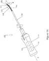
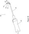
- Probe 100includes a proximal handle 102 , and a probe shaft 104 proximally connected to the handle and having a flexible cutting section 106 including a tip 108 at a cutting end.
- Cutting section 106includes a rotary cutting blade 110 for laterally cutting tissue.
- cutting section 106includes a frontal cutting blade 112 in tip 108 for forward cutting under tissue.
- probe 100is shown with cutting section 106 slightly flexed, tip 108 at a small angle ⁇ relative to a longitudinal axis "x" of handle 102 .
- Figure 1Bprobe 100 is shown with cutting section 106 flexed upwards, tip 108 at a relatively large angle ⁇ relative to a longitudinal axis "x" of handle 102.
- handle 102houses a motion controller 114 for controlling movement of components in the probe, including bending of cutting section 106 and operation of rotary cutting blade 110 and optionally frontal cutting blade 112.
- motion controller 114is adapted to rotate probe shaft 104 by up to 360°, shown by exemplary arrow A.
- motion controller 114is adapted to rotate cutting section 106 by up to 360°, shown by exemplary arrow B.
- Motion controller 114may include motorized means for controlling any one or all of bending cutting section 106 , rotating the cutting section and/or probe shaft 104 , operating rotating cutting blade 110 and frontal cutting blade 112.
- motion controller 114may include a mechanical mechanism which is manually operated by a user of probe 100 , for example by pulling a wire to cause bending of cutting section 106 or turning a knob for rotating the cutting section and/or probe shaft 104.
- motion controller 114may include an electronic controller and/or a hydraulic controller.
- motion controller 114controls movements responsive to signals received from a foot pedal operated by the physician.
- handle 102houses a controller 116 for controlling other operations not handled by motion controller 114. These operations may include, for example, imaging, aspiration, and irrigation, as well as interfacing with externally connected equipment associated with these operations.
- control circuitry 116 and motion controller 114are integrated as one unit.
- probe shaft 104is rigid along a portion of its length to flexible cutting section 106.
- probe shaft 104is flexible along its entire length.
- probe shaft 104is cylindrical in shape and includes an inner lumen 120 which extends from handle 102 to tip 108. Extending along a length of inner lumen 120 is a drive shaft 122 which is proximally connected to a motor in motion controller 114 and distally connects to rotary cutting blade 110 for imparting unidirectional rotary motion to the cutting blade.
- drive shaft 122is flexible and is adapted to bend with cutting section 106.
- delivery of fluids to the tissue cutting areais done through inner lumen 120.
- the fluidmay be supplied from a fluid source external to probe 100 , optionally connected to the probe through a connector (not shown) in proximal handle 102.
- the connectormay be adapted to connect to a syringe which may optionally form part of an intravenous (IV) fluid delivery device or other suitable fluid supply source.
- aspiration of cut tissueis done through inner lumen 120.
- an external aspiration deviceis connected to the connector in handle 102.
- aspiration and/or fluid deliverymay be done through a conduit 124 in probe shaft 122.
- rotary cutting blade 110 and drive shaft 122are removable for enabling surgical and/or other devices to be inserted through inner lumen 120 into the tissue cutting area.
- shielding between cutting edges 128 in cutting wheels 126 and tissue areas which are not to be cutis provided by the sheath-like enclosure of cutting section 106 wherein the only exposure of the cutting edges to an exterior of probe shaft 104 is through a window 118.
- Cutting section 106includes a cutting section wall 132 which partially encloses rotary cutting blade 110 and prevents cutting edges 128 from coming into contact with tissue.
- cutting edges 128 in cutting wheels 126protrude from a side of probe shaft 104 through window 118 for cutting tissue.
- a retractable cover 130may be rotatably adjusted to cover window 118 for preventing contact between tissue and rotary cutting blade 110 while probe 100 is inserted through the body into the tissue cutting area, and when removed from the tissue cutting area.
- retractable cover 130may be rotatably adjusted to partially cover window 118 for controlling an exposure area of cutting edges 128 to the tissue cutting area.
- FIGS 3A and 3Bschematically illustrate a perspective view of a section of a flexible rotary cutting blade 110 , according to an embodiment of the present invention.
- Rotary cutting blade 110is shown having rotary cutting wheels 126 connected to flexible drive shaft 122 and supported by drive shaft supports 136.
- Drive shaft supports 136are attached to a flexible base 134 adapted to bend with distal section 106 through the angle ⁇ .
- drive shaft supports 136 and flexible base 134include a hardened metal such as, for example, hardened stainless steel.
- rotary cutting blade 110is shown in a relatively straightened configuration.
- rotary cutting blade 110is shown in a flexed configuration.
- cutting section 106is a modular unit which may be modularly fitted as a single component onto probe shaft 104 .
- modular fitting of cutting section 106allows for easy installation and/or replacement of the cutting section, for example, when the blade is worn or depending on the surgical procedure to be performed (if the procedure involves the spine, the hip, the shoulder, or other organs) and the type of blade required for the procedure.
- modular fittingmay find practical application in a surgical probe kit including a disposable cutting section. An ordinary person skilled in the art may appreciate a potential advantage of having a surgical probe which may be used with different cutting sections.
- a vacuum sourcemay be attached to surgical probe 100.
- the vacuum sourceis connected through handle 102.
- a power sourcemay be connected to probe 100.
- probe 100includes an integral battery and a motor.
- FIG. 4schematically illustrates a perspective view of a cutting section 206 including a flexible housing 138 and a flexible rotary cutting blade 210 , according to some embodiments of the present invention.
- Rotary cutting blade 210is shown having rotary cutting wheels 126 connected to drive shaft 122 inside housing 138.
- Housing 138includes ribs 140 and slots 142 which allow the housing to flex together with rotary cutting blade 210 through the angle ⁇ .
- housing 138includes a hardened metal such as, for example, hardened stainless steel.
- cutting section 206is interchangeable with cutting section 106 and may be fitted onto probe shaft 104.
- FIG. 5schematically illustrates a perspective view of a cutting section 306 including a flexible rotary cutting blade 310 , according to some embodiments of the present invention.
- Rotary cutting blade 310is shown having rotary cutting wheels 126 connected to drive shaft 122 and supported by rigid drive shaft supports 140.
- Drive shaft supports 140are interconnected to one another by flexible members 142 for allowing flexing of cutting section 306 through the angle ⁇ .
- flexible members 142include tension springs.
- drive shaft supports 140 and the tension springs 142include a hardened metal such as, for example, hardened stainless steel.
- flexible members 142include elastomeric components.
- cutting section 306is interchangeable with cutting section 106 and 206 and may be fitted onto probe shaft 104.
- FIG. 6schematically illustrates a perspective view of an exemplary helically shaped rotary cutting blade 410 including a continuous spiraling cutting edge 146 , according to some embodiments of the present invention.
- Rotary blade 410is adapted to be used in cutting section 106 and is rotatable by shaft 122 relative to the longitudinal axis of probe shaft 104 for cutting tissue (with cutting edges 146A and/or 146B ).
- cutting blade 410includes right cutting edge 146A for cutting tissue when a right end 147A of the blade is rotated in a counterclockwise direction, as shown by arrow C.
- cutting blade 410includes a left cutting edge 146B for cutting tissue when a left end 147A of the blade is rotated in a counterclockwise direction, as shown by arrow D.
- cutting blade 410includes both cutting edges 146A and 146B for enabling tissue cutting independently of the direction of blade rotation.
- Rotary blade 410is further adapted to bend with cutting section 106 through the angle ⁇ .
- cutting blade 410includes a hardened metal such as, for example, hardened stainless steel.
- rotary cutting blade 410may be used with probes 100 having non-flexing cutting sections.
- rotary cutting blade 410is interchangeable with rotary cutting blades 110 - 310.
- rotary cutting blade 410removes cut tissue from the cutting area by transporting the cut tissue spirally along the blade in a proximal direction from tip 108 towards control handle 102.
- the cut tissueis aspirated through inner lumen 120 by an aspiration device (not shown) connected to probe 100.
- FIG. 7schematically illustrates an exemplary perspective view of a cylindrically shaped rotary cutting blade 510 including a continuous spiraling cutting edge 148 , according to some embodiments of the present invention.
- Rotary cutting blade 510is adapted to be used in cutting section 106 and is rotatable by shaft 122 relative to the longitudinal axis of probe shaft 104 for cutting tissue (with cutting edges 148 ).
- Rotary blade 510is further adapted to bend with cutting section 106 through the angle ⁇ .
- cutting blade 510includes a hardened metal such as, for example, hardened stainless steel.
- rotary cutting blade 510may be used with probes 100 having non-flexing cutting sections.
- rotary cutting blade 510is interchangeable with rotary cutting blades 110 - 410.
- rotary cutting blade 510includes openings 150 in cutting grooves 152 through which a fluid may be administered to the tissue cutting area.
- fluids in the tissue cutting areamay be aspirated into inner lumen 120 through openings 150.
- cut tissueis removed from the cutting area by transporting the cut tissue spirally along the blade inside cutting grooves 152 in a proximal direction from tip 108 towards control handle 102.
- Probe 600includes a probe shaft 604 to which a cutting section 606 having a window 618 and a rotary cutting blade 610 is connected through an articulating joint 601.
- rotary cutting blade 610is interchangeable with rotary cutting blades 110 - 510.
- probe shaft 604 and cutting section 606are relatively non-flexible.
- Articulating joint 601allows cutting section 606 to be displaced in three-dimensional space over angle ⁇ ranging from is - 130° to 130°, for example, -90°, -45°, 0°, 45°, 60°, 90°, relative to longitudinal axis "x" of a probe handle (not shown) for accessing concealed tissue regions not accessible using a straight instrument.
- articulating jointallows cutting section 606 to be displaced through angle ⁇ along a plane defined by an x-y axes, an x-z axes, or an y-z axes.
- articulating joint 601is adapted to allow probe shaft 604 to rotate up to 360° about longitudinal axis "x".
- cutting section 606may be rotated about its longitudinal axis for rotating window 618 to a different tissue cutting area in the vicinity of the cutting section the rotational movement shown by arrow E.
- rotating window 618prevents moving surgical probe 600 for accessing a different tissue cutting area surrounding cutting section 606 .
- Probe 700includes a probe shaft 704 to which a cutting section 706 having a rotary cutting blade 710 is rigidly connected at a predetermined angle ⁇ ranging from 30° to 150° relative to the longitudinal axis "x" of the probe handle, for example, 45°, 60°, 75°, 90°, 105°, 115°, 130°, 145°.
- probe shaft 704is rotatable clockwise and/or counterclockwise up to 360° about longitudinal axis "x”.
- Rotary cutting blade 710may be interchangeable with rotary cutting blades 110 - 610. ".
- cutting section 706may be rotated about its longitudinal axis for rotating window 718 to a different tissue cutting area in the vicinity of the cutting section, the rotational movement shown by arrow F.
- rotating window 718prevents moving surgical probe 700 for accessing a different tissue cutting area surrounding cutting section 706.
- Figure 10illustrates a flow graph of an exemplary method of performing a minimally-invasive surgical procedure for removing tissue using device 100 .
- An exemplary method for treating spinal stenosisis described further on below (see Figures 12A - 12D ).
- the physicianmakes an incision in the skin of a patient.
- the incisionis made in the vicinity of the shoulder, the hip, or the spinal column, for treating a condition in any one of these areas.
- a guiding tubesuch as a needle or an endoscopic tube is inserted through the incision and its distal end guided to the vicinity of the surgical area.
- the physicianinserts probe 100 through the guiding tube into the surgical area.
- the physicianPrior to insertion, the physician optionally activates an imaging device in probe 100 and verifies proper imaging . Additionally or alternatively, the physician may use an endoscopic device for imaging.
- the physicianmay have previously inserted a guide wire through the guiding tube for guiding surgical probe 100 to the tissue cutting area.
- the physicianguides probe 100 to the surgical area where tissue will be cut and removed.
- the physicianuses frontal cutting blades 112 for penetrating under tissue, including bone tissue, to reach the tissue cutting area.
- the physicianmanipulates control handle 102 for positioning cutting section 106 so that window 118 faces the tissue surface to be cut.
- cutting section 106is bent for reaching a tissue cutting area not in a direct line of sight.
- cutting section 106is rotated for aligning window 118 with the tissue surface.
- probe shaft 104is rotated.
- window 118faces an underportion of the tissue from inside a cavity opened by frontal cutting blade 112.
- all positioning and probe adjustmentsare made by motion controller 114 responsive to an activation signal by the physician (for example, pressing of one or more buttons on handle 102 or on a foot pedal).
- all positioning and probe adjustmentsare manually effected by the physician (for example, by pulling wires, turning knobs, and the like).
- retractable cover 130is manipulated to a desired size of window opening for exposing a portion of cutting edges 128.
- s a distance cutting edges 128 in rotary cutting wheels 126 protrude out window 118is adjusted using the blade adjustment mechanism.
- the physicianmay proceed to cut the tissue which is to be removed.
- the physicianmanually adjusts the cutting rate and the cutting amount.
- probe 100automatically adjusts cutting rate and tissue amount/size responsive to a signal received from an electromyogram or by detecting a resistance in the tissue to cutting..
- the physicianoptionally activates an aspiration mechanism externally connected to probe 100, optionally through handle 102, for removing cut tissue and fluids from the surgical area.
- the cut tissue/fluidsare aspirated through openings in cutting section 106 (for example, between cutting wheels 126 or through other openings in the cutting section, including window 118 ) into inner lumen 120 in a proximal direction towards control handle 102.
- conduit 124 in drive shaft 122is also used for aspirating the cut tissue and fluids.
- medicationsuch as an antibiotic, a sterilizing fluid, and/or a pain relieving medication is optionally delivered through probe 100 to areas where tissue was cut.
- the medicationis delivered through inner lumen 120. Additionally or alternatively, the medication is delivered through conduit 124.
- physiciancloses window 118 and prepares probe 100 for removal from body, including adjusting a position of cutting section 106 so that it does not interfere with probe 100 movement during the extraction.
- the physicianguides probe 100 out of the surgical area and through the body out the guiding tube. Following probe 100 removal, the guiding tube is removed and the incision may then be closed.
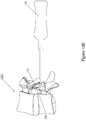
- FIG. 11illustrates a block diagram of a minimally-invasive surgical probe kit 1100 for treating spinal stenosis.
- surgical probe kit 1100may be used for treating other conditions requiring tissue removal in the spinal column, the shoulder joint, the hip joint, or other organ.
- Surgical probe kit 1100includes a surgical probe 1101 having a flexible cutting section 1106 for lateral cutting of tissue.
- flexible cutting section 1106includes a frontal cutting tool for forward cutting under tissue.
- surgical probe 1101is a single-use device which is disposed of following use in a surgical procedure.
- kit 1100may include a control handle 1102 and a probe shaft 1104 having a cutting section 1106 including a rotary cutting blade.
- probe shaft 1104is a single-use component which is disposed of and replaced following a surgical procedure.
- the cutting section 1106is detachable from probe shaft 1104 and is removed and replaced following the surgical procedure.
- replacement of cutting section 1106includes replacement of the drive shaft.
- Figures 12A - 12Dschematically illustrate an exemplary method for treating spinal stenosis in a vertebral column 1200 using surgical probe 100 .
- the stenosisis a foraminal stenosis.
- the stenosisis a central stenosis.
- a needle 1202is inserted through a cavity 1201 in vertebral column 1200 in proximity to the area of the stenosis.
- probe 100is inserted, with cutting section 106 coaxially aligned with the longitudinal axis of the probe, into needle 1202 and advanced until distal tip 108 reaches the surgical site.
- cutting blade 110is operated to start cutting tissue and the irrigation and aspiration is operated to remove the cut tissue.
- frontal cutting blade 112is operated prior to operation of cutting blade 110 , or alternatively, together with the cutting blade.
- Feedbackis constantly received by the surgeon (for example, torque resistance applied on the motor) for making a decision when to advance the probe forward.
- Other feedbackmay be received using any one or any combination of light, sound, computer generated sound, vibration, x-ray imaging, or human sensory perception by feeling resistance to moving the probe or by monitoring an amount of cut tissue being washed up.
- the surgeonupon determining that an adequate amount of tissue has been removed in front of tip 108 , the surgeon initiates bending of cutting section 106 while cutting and steering (including pushing) the device forward for advancing tip 108 into tissue areas that are not directly in front of needle 1202.
- thismay be done by using cutting, bending and advancing functions simultaneously until tip 108 is in the desired place.
- further tissuecan be removed using retraction of probe 100 with cutting section 106 bent, or rotating the device over its longitudinal axis, or a combination of both movements.
- probe 100is withdrawn from the body using bending and retraction until it is straightened and may be pulled back from the needle.
- Figure 13is schematically illustrated an exemplary surgical probe 1300 including a cutting section 1306 having a rotary cutting blade 1310 with rotary cutting wheels 1326 forming an angle ⁇ with a longitudinal axis of the probe, according to some embodiments of the present invention.
- Surgical probe 1400including a plurality of lumens (conduits) suitable for fluid conduction and/or aspiration, according to some embodiments of the present invention.
- Surgical probe 1400includes an inner lumen 1420 in probe shaft 1404 , a first lumen 1425 and second lumen 1427 inside the inner lumen, and a drive shaft conduit 1424 in drive shaft 1422.
- First and second lumens 1425 and 1427include an opening 1429 at a distal end leading into a cavity 1431 in cutting section 1406 housing rotary cutting blade 1410.
- a probemay include 1, 2, 3, 4, or a greater number of conduits.
- FIG. 15is schematically illustrated an exemplary surgical probe 1500 including a blade adjustment mechanism 1531 in a cutting section 1506 , according to some embodiments of the present invention.
- blade adjustment mechanism 1531adjusts a protrusion from cutting section 1506 of cutting edges 1528 in rotary cutting wheels 1526.
- blade adjustment mechanism 1531includes a pivotal cam mechanism 1539 adapted to act on a plurality of driving shaft supports 1536 , raising and lowering the supports.
- Driving shaft supports 1536support a flexible driving shaft 1522 which is maintained in alignment by a linear guide 1537 which aligns driving shaft supports 1536.
- FIGs 16A and 16Bare schematically illustrated an exemplary surgical probe 1600 including a distal section 1606 attached to an articulating joint 1601 (a hinge) and including frontal cutting tools 1612 and 1613 , respectively, according to some embodiments of the present invention.
- surgical probe 1600includes a rotary cutting blade 1610 for lateral cutting.
- FIG 16Asurgical probe 1600 is shown with frontal cutting tool 1612 covering a portion of a cross-section of the tip at the distal end of the probe.
- FIG 16Bsurgical probe 1600 is shown with frontal cutting tool 1612 covering the full cross-section of the tip at the distal end of the probe.
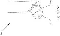
- FIGs 17A and 17Bare schematically illustrated perspective views of an exemplary probe including an articulating (hinged) telescopic tip 1708 and a frontal cutting tool 1712 , according to some embodiments of the present invention.
- tip 1708is shown in a closed retracted position, while in Figure 17B tip 1708 is shown in an open expanded position.
- frontal cutting tool 1712may be used when telescopic tip 1708 is partially opened.
- opening and closing of telescopic tip 1708is by means of a push wire (not shown).
- Movement mechanism 1803includes at least one pull wire 1801 positioned off-axis of a natural bending axis 1805 of cutting section 1806 and attached to a distal end of the cutting section. Pulling of pull wire 1801 will cause the side of cutting section 1806 where the wire is located to be shortened relative to the opposing side, bending the cutting section.
- a pull wiremay be included off-axis on each side of natural bending axis 1805 for allowing bending in opposing directions. For example, two or three or more such wires are provided.
- at least one wireis attached at a different axial location from other wires, supporting more complex bending shapes.
- a conduitis used to pass a shaping stylet.
- Movement mechanism 1903includes a push/pull rod 1905 which extends through probe shaft 1904 and connects to a hinge 1907 in cutting section 1906.
- Hinge 1907is positioned such that pushing or pulling of rod 1905 will cause cutting section 1906 to rotate about hinge 1901 such that a distal tip 1908 will move in a direction opposite to that of rod 1905.
- compositions, method or structuremay include additional ingredients, steps and/or parts, but only if the additional ingredients, steps and/or parts do not materially alter the basic and novel characteristics of the claimed composition, method or structure.
- methodrefers to manners, means, techniques and procedures for accomplishing a given task including, but not limited to, those manners, means, techniques and procedures either known to, or readily developed from known manners, means, techniques and procedures by practitioners of the chemical, pharmacological, biological, biochemical and medical arts.
Landscapes
- Health & Medical Sciences (AREA)
- Surgery (AREA)
- Life Sciences & Earth Sciences (AREA)
- Biomedical Technology (AREA)
- Medical Informatics (AREA)
- Veterinary Medicine (AREA)
- Public Health (AREA)
- Engineering & Computer Science (AREA)
- General Health & Medical Sciences (AREA)
- Heart & Thoracic Surgery (AREA)
- Nuclear Medicine, Radiotherapy & Molecular Imaging (AREA)
- Molecular Biology (AREA)
- Animal Behavior & Ethology (AREA)
- Orthopedic Medicine & Surgery (AREA)
- Dentistry (AREA)
- Oral & Maxillofacial Surgery (AREA)
- Surgical Instruments (AREA)
Description
- This application claims the benefit of United States Provisional Application No.
61/361,930 filed on 7 July 2010 - The present invention, in some embodiments thereof, relates to surgical devices for removing tissue from body organs.
- Minimally-invasive surgery generally involves use of endoscopic or similar devices which may be inserted through incisions in the skin, through body cavities, and/or through other anatomical openings. The procedures frequently involve remote-control manipulation of instruments for removing tissue from body organs, such as in the circulatory system, digestive system, nervous system, muscular system, skeletal system, and the other systems of the body. Occasionally, the tissues are difficult to access or may be positioned close to organs which are delicate and relatively easily damaged. This may require that additional incisions be made in the body for accessing the area and/or for introducing additional surgical instruments and/or facilitating operation of the instruments.
- Spinal stenosis is an example of a condition where tissue removal is made relatively difficult due to the difficulty in accessing the spinal canal (neuroforamen) and the proximity to the spinal cord. Devices and methods have been suggested in the art which attempt to treat conditions such as those of spinal stenosis using minimally-invasive surgery.
- U.S. Patent Publication
US 2006/0200155 to Harp describes "a reciprocating surgical file system for precisely removing bone and/or other tissue. The system allows a user to maneuver the system and navigate into hard-to-access sites under a direct vision mechanism. A transmission mechanism converts rotary motion from a motor into reciprocating motion and provides it to the surgical file for precision removal of bone or other tissue. A pulsatile pump mechanism is operatively coupled with the transmission mechanism and provides irrigating fluid to the surgical site." - German Patent Publication
DE 10360076 to Möbius and Ruppert describes a Surgical instrument used as drill for making curved bore in bone to accommodate prosthesis. The drill for making a curved bore in bone has a toothed spiral spring rotating on a rigid curved and tapered core covered with a bearing sheath. - U.S. Patent Publication
US 2008/0004645 to To and Danek describes devices and methods for clearing obstructions within body lumens. In one variation a device is described as including a flexible body having a cutter head with spaced cutter edges and wherein the cutter head includes a housing. - U.S. Patent Publication
US 2006/0135882 to Bleich describes "methods and apparatus are provided for selective surgical removal of tissue. In one variation, tissue may be ablated, resected, removed, or otherwise remodeled by standard small endoscopic tools delivered into the epidural space through an epidural needle. The sharp tip of the needle in the epidural space, can be converted to a blunt tipped instrument for further safe advancement. The current invention includes specific tools that enable safe tissue modification in the epidural space, including a barrier that separates the area where tissue modification will take place from adjacent vulnerable neural and vascular structures. A nerve stimulator may be provided to reduce a risk of inadvertent neural abrasion." U.S. Patent 7189240 to Dekel describes "a method of treating spinal stenosis, in which a rasp is brought through a part of a spinal channel and then axially moved so that the rasp removes a stenosis in the spinal channel. Optionally, a shield protects a spinal cord or other sensitive tissues in the spinal channel."- Additional background art includes
U.S. Patent Publications 2006/0089609 ,2006/0241648 ,2008/0086034 ,2009/0036936 ,2009/0143807 ,2010/0262147 ,2008/0183175 ,2008/0183192 ,2008/0221605 ,2010/0082033 ,2010/0211076 ,2006/0200155 ,2010/0286695 ,2010/0298832 ;U.S. Patents 6558390 ,7014633 ; U.S. Design PatentsD611146 ,D606654 ; Foreign PatentNL1009471 - The scope of the invention and its protection is defined by appended claim 1. Preferred embodiments are described in the dependent claims.
- Unless otherwise defined, all technical and/or scientific terms used herein have the same meaning as commonly understood by one of ordinary skill in the art to which the invention pertains. Although methods and materials similar or equivalent to those described herein can be used in the practice or testing of embodiments of the invention, exemplary methods and/or materials are described below. In case of conflict, the patent specification, including definitions, will control. In addition, the materials, methods, and examples are illustrative only and are not intended to be necessarily limiting.
- Implementation of the system of embodiments of the invention can involve performing or completing selected tasks manually, automatically, or a combination thereof. Moreover, according to actual instrumentation and equipment of embodiments of the system of the invention, several selected tasks could be implemented by hardware, by software or by firmware or by a combination thereof using an operating system.
- For example, hardware for performing selected tasks according to embodiments could be implemented as a chip or a circuit. As software, selected tasks according to embodiments could be implemented as a plurality of software instructions being executed by a computer using any suitable operating system. In an exemplary embodiment, one or more tasks according to exemplary embodiments of method and/or system as described herein are performed by a data processor, such as a computing platform for executing a plurality of instructions. Optionally, the data processor includes a volatile memory for storing instructions and/or data and/or a non-volatile storage, for example, a magnetic hard-disk and/or removable media, for storing instructions and/or data. Optionally, a network connection is provided as well. A display and/or a user input device such as a keyboard or mouse are optionally provided as well.
- Some embodiments of the invention and examples are herein described, by way of example only, with reference to the accompanying drawings. With specific reference now to the drawings in detail, it is stressed that the particulars shown are by way of example and for purposes of illustrative discussion of embodiments of the invention. In this regard, the description taken with the drawings makes apparent to those skilled in the art how embodiments of the invention may be practiced.
Figure 1A schematically illustrates a perspective view of an exemplary surgical probe having a slightly flexed distal end, according to an embodiment of the present invention;Figure 1B schematically illustrates a perspective view of an exemplary surgical probe having a relatively large flexed distal end, according to an embodiment of the present invention;Figure 2 schematically illustrates a perspective view of a probe shaft in a relatively non-flexed configuration and including a rotary cutting blade having rotary cutting wheels, according to an embodiment of the present invention;Figure 3A schematically illustrates a perspective view of a section of a flexible rotary cutting blade in a relatively straightened configuration, according to an embodiment of the present invention;Figure 3B schematically illustrates a perspective view of a section of a flexible rotary cutting blade in a flexed configuration, according to an embodiment of the present invention;Figure 4 schematically illustrates a perspective view of a rotary cutting blade, according to some embodiments of the present invention;Figure 5 schematically illustrates a perspective view of a rotary cutting blade, according to some embodiments of the present invention;Figure 6 schematically illustrates an exemplary perspective view of a helically shaped rotary cutting blade including a continuous spiraling cutting edge, according to some embodiments of the present invention;Figure 7 schematically illustrates an exemplary perspective view of a cylindrically shaped rotary cutting blade including a continuous spiraling cutting edge, according to some embodiments of the present invention;Figure 8 schematically illustrates a perspective view of an exemplary minimally-invasive surgical probe, according to some embodiments of the present invention;Figure 9 schematically illustrates a perspective view of an exemplary minimally-invasive surgical probe, according to some embodiments of the present invention;Figure 10 illustrates a flow graph of an exemplary method of performing a minimally-invasive surgical procedure for removing tissue using the surgical probe ofFigures 1A and1B ;Figure 11 illustrates a block diagram of a minimally-invasive surgical probe kit, according to some embodiments of the present invention;Figures 12A - 12D schematically illustrate steps in an exemplary method for treating spinal stenosis in a vertebral column using a surgical probe, according to some embodiments;Figure 13 schematically illustrates an exemplary surgical probe including a cutting section having a rotary cutting blade with rotary cutting wheels forming an angle θ with a longitudinal axis of the probe, according to some embodiments of the present invention;Figure 14 schematically illustrates an exemplary surgical probe including a plurality of lumens (conduits) suitable for fluid conduction and/or aspiration, according to some embodiments of the present invention;Figure 15 schematically illustrates an exemplary surgical probe including a blade adjustment mechanism in a cutting section, according to some embodiments of the present invention;Figures 16A and16B schematically illustrate an exemplary surgical probe including a distal section attached to an articulating joint and including frontal cutting tools, according to some embodiments of the present invention;Figures 17A and17B schematically illustrate perspective views of an exemplary probe including an articulating telescopic tip and a frontal cutting tool, according to some embodiments of the present invention;Figures 18A and18B schematically illustrate an exemplary movement mechanism for bending a flexible cutting section in a surgical probe, according to some embodiments of the present invention; andFigure 19 schematically illustrates an exemplary movement mechanism for a surgical probe having an articulation joint, according to some embodiments of the present invention.- The present invention, in some embodiments thereof, relates to surgical devices and, more particularly, but not exclusively, to an apparatus for removing tissue from body organs.
- An aspect of some embodiments of the present invention relates to a surgical probe including a cutting section with an optional shield and having a cutting blade for laterally cutting tissue from body organs. In an exemplary embodiment of the invention, the probe, which optionally includes a proximal control handle for manipulating the probe and a probe shaft including the cutting section, is adapted to be placed laterally against tissue and to selectively cut only tissue exposed to the cutting blade while shielding surrounding tissue from the blade. Optionally, a tissue cutting rate is greater than 1 mm3 per second for cortical bone, for example, 5 mm3/sec, 10 mm3/sec, 15 mm3/sec, 25 mm3/sec, or greater or intermediate values. Optionally, the cutting section is rotatable (e.g., relative to the handle) up to 360° or more (or smaller angles, such as up to 90°, up to 180° or up to 270° degrees, or intermediate angles) about its longitudinal axis for exposing the cutting blade to different tissue areas surrounding, or partially surrounding, the cutting section, as required. Additionally or alternatively, the shielding section of the cutting section is rotatable about the longitudinal axis for exposing different sections of the cutting blade to the surrounding tissue. Additionally, the probe is further adapted to maneuver the cutting section including the rotary cutting blade into tissue regions inaccessible with straight instruments, for example, the neuroforamen in the spinal column; the acromium, humerus, and scapula in the shoulder; and the femur and the acetabulum in the hip. In some embodiments, maneuvering includes introducing the probe into an organ from an anterior side of the organ for reaching a posterior side of the organ, or inversely, introducing the probe from the posterior side of the organ for reaching the anterior side. Additionally, maneuvering may include bending the cutting section and/or rotating the cutting section for exposing the cutting blade to the tissue cutting area. Optionally, the probe may be used for removing bone spurs, and for surface preparation (decortication) for reconstructing ligament-bone attachments. In some embodiments, the cutting section may include extendible side supports which press against the tissue surrounding the cutting area for preventing torsion of the cutting section during cutting. Optionally, the side support may include a wing shape.
- In an exemplary embodiment of the invention, the cutting section is replaceable with a cutting section of other degree of roughness, for example, to smooth a cut section.
- In an exemplary embodiment of the invention, cutting in the spine includes advancing the tip of a probe to a spinal canal and activating the forward cutter to cut into bone. The probe may then be bent and advanced into the cut channel, remaining between the ligament and the bone or wholly within the bone. As the probe is advanced, the lateral cutting section can be used to cut against the bone. The probe can then be advanced and bend again, as needed. Optionally, this process is under control of a user who senses the resistance of the bone to cutting, for example, by an indicator (e.g., a visual or acoustic torque indicator) or based on the feel of the instrument or its sound.
- In some exemplary embodiments, the cutting section is flexible and bendable for reaching the otherwise inaccessible regions. Optionally, the cutting section is axially bendable so that a distal tip of the cutting section forms an angle α ranging from - 270° to 270° relative to a longitudinal axis of the probe handle, for example, - 230°, - 200°, - 150°, - 90°, 0°, 90°, 150°, 200°, 230°. Optionally, the cutting section is bendable in three-dimensional space (x-y-z planes). In some embodiments, the bending is controlled by a user and may be varied as the user cuts through the tissue. Alternatively, the cutting section is rigid and is connected in the probe by means of an articulating joint for allowing the cutting section to be positioned in three-dimensional space at an angle γ ranging from is - 130° to 130°, for example, -90°, -45°, 0°, 45°, 60°, 90°. Alternatively, the cutting section is rigidly connected in the probe at a predetermined angle β ranging from 30° to 150° relative to the longitudinal axis of the probe handle, for example, 45°, 60°, 75°, 90°, 105°, 115°, 130°, 145° or intermediate values.
- In some embodiments of the invention, the bending is such that the cutting shape is concave along the longitudinal axis. In some embodiments, the bending is convex. In some embodiments, the bending is both concave and convex, e.g., at different portions. Optionally or alternatively, bending in the plane of the cutting section is provided.
- In an exemplary embodiment of the invention, the bending is between two cutting edges of the cutting section, for example, if the cutting section includes a flexible blade, or if multiple blades are provided and bending is between them. In an exemplary embodiment of the invention, the bending is at a distal end of the device (e.g., within 1-5 cm from its end, for example, 2 or 3 cm), but optionally not in the bending section.
- In some embodiments, all the cutting section is bendable. In others, only certain parts thereof are designed to bend.
- In some embodiments of the invention, for a flexible or for a rigid cutting section, a telescoping cutter is provided.
- In some embodiments, abrasive heads or other tissue removal means are provided instead of or in addition to cutting edges.
- In some exemplary embodiments, the rotary cutting blade rotates about a longitudinal axis of the probe. The cutting blade is sheathed inside the cutting section which protectively shields surrounding tissue from inadvertent cutting while allowing selective and directional protruding of cutting edges for tissue cutting. Optionally, the cutting edges protrude from the cutting section between 0.1 mm to 4 mm, depending on the type of tissue to be removed. For example, the cutting edge may protrude 0.3 mm, 0.6 mm, 0.9 mm, 1.2 mm, 1.8 mm, 2.3 mm, 2.9 mm, 3.3 mm, 3.5 mm, 3.8 mm. In some embodiments, a blade control mechanism varies the protrusion of the cutting edges for controlling a tissue cutting rate and/or a tissue cutting amount and/or size. Optionally, the protrusion of the cutting edges may be varied along a length of the cutting blade for varying a tissue cutting rate along the cutting section and/or a tissue cutting amount and/or size in the tissue cutting area.
- In some exemplary embodiments, the cutting section includes a window through which the cutting edges protrude for cutting tissue. Optionally, a retractable cover may be placed over the window for covering the cutting edges and preventing possible organ damage while the probe is directed to the area of tissue removal, and while removed from the area. The retractable cover may be positioned inside the cutting section and may be slidingly rotated about the longitudinal axis of the cutting end for covering and uncovering the window. Alternatively, the retractable window cover may be slid along the longitudinal axis of the cutting section for covering and uncovering (wholly or partially) the window. Additionally or alternatively, the retractable cover is adapted to cover part of the window for concealing a portion of the cutting edges which would otherwise protrude through the window, for reducing a size of the tissue cutting area.
- An aspect of some embodiments of the present invention relates to a surgical probe having a flexible cutting section with a bending point between two cutting edges, for example, between two cutting wheels and/or between a lateral cutting section and a forward cutting section. In some exemplary embodiments, the rotary cutting blade includes a plurality of axially arranged cutting wheels having circumferentially-positioned cutting edges and adapted to rotate about the longitudinal axis of the probe; for example, 2 cutting wheels, 3 cutting wheels, 5 cutting wheels, 12 cutting wheels, or more. Using a plurality of cutting wheels provides for a cutting blade with greater flexibility compared with that of a single long flexible cutting blade, and at a potentially lower manufacturing cost. Optionally, a direction of cutting may be better controlled using multiple cutting wheels. Optionally, a relative position of each cutting wheel, relative to the longitudinal axis of the probe handle, varies as the cutting section is flexed through the angle α. In some embodiments, the cutting wheels may be of a same diameter while in other embodiments one or more cutting wheels may have a diameter different than that of other cutting wheels. Optionally, the cutting wheels along the tip may vary in width, type of cutting blade, material, blade and groove design, for potentially better handling of different types of tissues, better disposal of the cut tissue, and the like. Alternatively, the rotary cutting blade is a single helically shaped blade having a continuous spiraling cutting edge. Optionally, the helical shaped cutting blade is flexible and bends together with the cutting section through the angle α. Alternatively, the rotary cutting blade is a single cylindrically shaped blade and has a spiraling cutting edge. Optionally, the cylindrically shaped cutting blade is flexible and bends together with the cutting section through the angle α. In some embodiments, the spiraling cutting edge(s) may serve to transport the cut tissue in a proximal direction away from the tip. In some embodiments, the continuous rotating cutting blade may include a fixed shape and/or geometry along the rotation axis. Alternatively, the blade may include a graduated variation in diameter, for example, conical-helical shape. Additionally or alternatively, the blade may include a graduated variation of pitch, for example, the distance between windings varies. Additionally or alternatively, the blade may include a graduated variation of blade geometry for handling different types of tissues
- In some exemplary embodiments, the rotary cutting blade is made of a hardened biocompatible material and may include a steel or metal alloy such as, for example, hardened stainless steel or other hardened metal. Alternatively, for a non-bending rotary cutting blade, a ceramic material may be used. Alternatively, the cutting wheels may include the ceramic material A length of the rotary cutting blade may range from 1 mm to 100 mm, for example, 2 mm, 5 mm, 7 mm, 11 mm, 25 mm, 50 mm, 75 mm. An outer diameter of the rotary cutting blade may range from 0.5 mm to 6 mm, for example, 1 mm, 2 mm, 3 mm, 4 mm, 5 mm.
- In some exemplary embodiments, the flexible cutting section includes a flexible base with a plurality of attached supports for supporting a flexible drive shaft. The flexible drive shaft may be made from material such as a twisted or wound stainless steel cable, a helical spring, or an assembly of springs and/or cables, and may include a conduit for transferring fluids through the conduit. A diameter of the conduit in the drive shaft may range from 0.3 mm to 2.5 mm, for example, 0.8 mm, 1.2 mm, 1.5mm, 1.8 mm, 2.2 mm. The rotary cutting blade includes the plurality of cutting wheels which are rotatably attached to the drive shaft. Alternatively, the supports are interconnected by flexible members, for example, springs or elastomeric material, for providing flexibility to the cutting section. Alternatively, the rotary cutting blade includes the flexible helical-shaped blade. Alternatively, the rotary cutting blade includes the flexible cylindrically shaped blade. Alternatively, the flexible cutting section includes a flexible housing having grooves which provide flexibility.
- In some exemplary embodiments, the probe includes a movement mechanism for moving the cutting section. Optionally, bending may be effected by pulling a wire which extends from the handle through the probe to the cutting section. Alternatively, the movement mechanism moves the cutting section attached to the articulating joint. Optionally, the movement mechanism includes a push/pull rod which runs through the probe and is operated by a lever. Optionally, the lever is in the handle. In some embodiments the movement mechanism rotates the probe shaft and/or cutting section about their longitudinal axis. In some embodiments, the movement mechanism includes motors for performing some or all of the moving actions (bending, rotating, articulating).
- In some exemplary embodiments, the rotary cutting blade is rotated by the drive shaft connected to a motor. A rotational speed of the cutting blade may range from 100 RPM (revolutions per minute) to 30000 RPM or more, for example, 500 RPM, 200 RPM, 8000 RPM, 15000 RPM, 25000 RPM, 35000 RPM, 50000 RPM. The motor may be an electrically operated motor powered by AC (alternating current) or DC (direct current), for example, with batteries. Alternatively, the motor is a pneumatically operated motor. Alternatively, the cutting blades are hydraulically driven by a relatively high pressure fluid circulated through the probe. Optionally, the drive shaft is flexible and bends together with the cutting section through the angle α. In some embodiments, the surgical probe may be a hand-held device.
- In some exemplary embodiments, the probe shaft is hollow and includes an internal lumen for accommodating the drive shaft. A cross-sectional outer diameter of the probe shaft may range from 1 mm - 6 mm, for example, 2 mm, 3 mm, 4mm. An internal lumen diameter may range from 0.5 mm - 2.5 mm, for example, 1 mm, 1.5 mm, 2 mm. A length of the probe shaft may range from 30 mm - 500 mm, for example, 50 mm, 80 mm, 120 mm, 150mm, 190 mm, 250 mm, 325 mm, 450 mm. Optionally, the longer lengths of probe shaft enable tissue cutting along the length of bones. In some embodiments, the probe shaft is made of a rigid biocompatible material. Optionally, the rigid probe shaft includes the flexible cutting section. Alternatively, the probe shaft is made of a flexible biocompatible material, for example, Nitinol, and includes the flexible cutting section.
- In some exemplary embodiments, the probe shaft includes a conduit for delivering a biocompatible and/or biodegradable fluid to the tissue removal area. Optionally, the fluid includes a medicinal fluid for administering a drug to the tissue area, for example an antibiotic. Additionally or alternatively, the fluid includes a cleaning fluid for flushing the tissue cutting area for allowing improved imaging of the area. Additionally or alternatively, the probe shaft includes a conduit for removing cut tissue out of the body, for example by connecting an aspiration device to the probe. A fluid flow rate through the conduits may range from between 0.1 cc/sec - 2 cc/sec, for example, 0.5 cc/sec, 1 cc/sec, 1.5 cc/sec. Additionally or alternatively, the probe shaft includes a conduit for transporting surgical or other medical devices to the tissue cutting area. Optionally, the internal lumen may serve some or all the above functions of the conduits. Additionally or alternatively, a conduit in the drive shaft may serve some or all of the above functions. In some embodiments, the conduit may have a continuous passage to the rotating blade such that the fluid flows from the probe shaft to the rotating blade and optionally, through openings in the blade to the surgical site. Additionally or alternatively, aspiration is done through the openings in the blade and through the conduit.
- In some exemplary embodiments, the probe includes a medical imaging device for allowing tracking of the position of the probe inside the body. The imaging device may include tracking means such as, for example, an optical system on its distal tip to allow imaging of the tip proximity, for example for video imaging or infrared imaging; a magnetic transmitter or receiver where the other of transmitter or receiver is located outside the body; a radiofrequency transmitter or receiver where the other of transmitter or receiver is located outside the body; an ultrasound transmitter or receiver where the other of transmitter or receiver is located outside the body.
- In some exemplary embodiments, the probe is inserted into the body and approximated to the tissue cutting area through a needle. Alternatively, the probe is inserted through a cannula. Alternatively, the probe is inserted through a working channel of an endoscope. Additionally or alternatively, the probe may be directed to the tissue cutting area by means of a guidewire connecting the probe. Optionally, an imaging device such as an endoscope, or similar, is used to track the position of the probe.
- In some exemplary embodiments, the probe automatically regulates a rate of tissue cutting based on detection of a signal, optionally a feedback signal, associated with nerve activity or resistance of the tissue to being cut. Optionally, the detection is by electromyography or using other methods known in the art., with a controller in the probe controlling probe operation responsive to a signal received from an externally connected electromyogram. Additionally or alternatively, the controller automatically regulates an amount and/or size of tissue cutting based on the detected mechanical and/or physiological signal. Additionally or alternatively, the controller controls a cutting speed and/or a cutting torque responsive to a sensor in the probe sensing tissue information which may include a type of tissue being contacted, a length of tissue being contacted, a termination of the tissue being contacted. Optionally, the controller notifies the physician responsive to the detection through a visual and/or audible signal.
- An aspect of some embodiments of the present invention relates to a surgical probe including a frontal cutting tool for enabling the probe to frontally penetrate under tissue. In some embodiments, the frontal cutting tool is included in a distal tip of the probe. Optionally, the tip is followed by a cutting section for laterally cutting into tissue. Optionally, the cutting section includes a rotary cutting blade. Alternatively, the cutting section includes a rasp (for filing the tissue). The frontal cutting tool is adapted to open a path under the tissue for inserting the tip followed by the cutting section. This feature may be particularly advantageous in applications where a natural cavity adjacent to the tissue cutting area is not available for insertion of the probe (for example, when tissue growth in the spinal cavity between the neuroforamen wall and the spinal cord completely blocks the canal so that an instrument cannot be inserted without contacting the spinal cord). Optionally, the frontal cutting tool is a rotary cutting blade. Rotary motion causes a relative movement of the blade with the tissue to be cut, and the penetration of the blade into the outer surface of the tissue cuts small chips of tissue which are separated from the remaining of the tissue. Such penetration is initially achieved using normal forces the blade applies on the tissue which may vary from 10 s-100s mN for eroding to 10s N in cutting. Alternatively, the frontal cutting tool includes any other type of tissue removal tool suitable for penetrating into the tissue, for example, a burr, a drill bit, a rasp. Additionally or alternatively, the tip may include a rotating or vibratory element having a rough surface texture (abrasive) for eroding the tissue for allowing the tip to frontally penetrate into the tissue.
- In an exemplary embodiment of the invention, a same power source, e.g., possibly including a shared drive shaft, is used for lateral and forward cutting sections. Optionally, some axial motion of the drive shaft is provided to assist in the cutting.
- An aspect of some embodiments of the present invention relates to a surgical probe having a cutting section for lateral cutting into tissue and a frontal cutting tool for enabling the probe to frontally penetrate under the tissue.
- An aspect of some embodiments of the present invention relates to a kit including the surgical probe for use in the treatment of spinal stenosis Additionally or alternatively, the kits may be used for treating other conditions requiring tissue removal from body organs, for example, in the shoulder or the hip. In some embodiments, the probe is a single-use device which is disposed of following surgical use. Alternatively, the probe shaft including the cutting section, the cutting blade, and the drive shaft are disposed of and replaced following one-time use. Alternatively, the cutting section including the cutting blade and the drive shaft are disposed of and replaced following one-time use. Optionally, the cutting section includes the frontal cutting tip. Alternatively, only the rotary cutting blade and the drive shaft are disposed of and replaced. Optionally, the frontal cutting blade is disposed of and replaced.
- An aspect of some embodiments relates to an exemplary method of forward cutting under body tissue. Optionally, forward cutting of the body tissue is followed by removal of the tissue through lateral cutting. Optionally, the method includes penetrating into an under-portion of the tissue using a frontal cutting tool and forming a cavity wherein a lateral tissue cutting tool may be accommodated. Optionally, once inside the cavity, the lateral tissue cutting tool may laterally cut away at the tissue in a direction towards a tissue surface (external direction). Additionally or alternatively, the lateral tissue cutting tool may laterally cut in a direction away from the tissue surface (internal direction), deeper into the tissue. Lateral cutting may include any one or combination of cutting (with a blade), rasping, burring, and eroding. Forward cutting may include any one or combination of cutting, drilling, burring, eroding (through abrasion), and rasping.
- For example, such cutting may be used with arthroscopic or endoscopic tools, for example, for cutting bone under a ligament or bone under cartilage or muscle.
- The devices disclosed herein, in some embodiments, are technically advantageous over the prior art as they do not require insertion into natural cavities adjacent to tissue cutting areas for cutting tissue, as required by the prior art. For example, in treating spinal stenosis prior art teaches inserting the surgical device into the neuroforamen for accessing the tissue cutting area. An additional advantage is that use of the devices require only one incision be made in the body, potentially simplifying the surgical procedure and resulting in faster patient post-surgical recuperation.
- Other potential advantages, in some exemplary embodiments, rest in the possible preventing of ligament inflammation by attempting to not cut ligaments. Although some embodiments may include ligament cutting, other embodiments may not require such cutting. Additional advantages, in some exemplary embodiments, is the that blade bends to substantially match the shape of the surface of the bone. Other advantages include, in some exemplary embodiments, urging the cutting surfaces of ligaments or other tissues against the bone surface.
- Before explaining at least one embodiment of the invention in detail, it is to be understood that the invention is not necessarily limited in its application to the details of construction and the arrangement of the components set forth in the following description and/or illustrated in the drawings and/or the Examples. The invention is capable of other embodiments or of being practiced or carried out in various ways.
- Reference is now made to
Figures 1A and1B which schematically illustrate perspective views of an exemplary minimally-invasivesurgical probe 100, according to an embodiment of the present invention.Probe 100 includes aproximal handle 102, and aprobe shaft 104 proximally connected to the handle and having aflexible cutting section 106 including atip 108 at a cutting end. Cuttingsection 106 includes arotary cutting blade 110 for laterally cutting tissue. Optionally, cuttingsection 106 includes afrontal cutting blade 112 intip 108 for forward cutting under tissue. InFigure 1A ,probe 100 is shown withcutting section 106 slightly flexed,tip 108 at a small angle α relative to a longitudinal axis "x" ofhandle 102. InFigure 1B ,probe 100 is shown withcutting section 106 flexed upwards,tip 108 at a relatively large angle α relative to a longitudinal axis "x" ofhandle 102. - In some exemplary embodiments, handle102 houses a
motion controller 114 for controlling movement of components in the probe, including bending of cuttingsection 106 and operation ofrotary cutting blade 110 and optionallyfrontal cutting blade 112. Optionally,motion controller 114 is adapted to rotateprobe shaft 104 by up to 360°, shown by exemplary arrow A. Additionally or alternatively,motion controller 114 is adapted to rotate cuttingsection 106 by up to 360°, shown by exemplary arrowB. Motion controller 114 may include motorized means for controlling any one or all of bendingcutting section 106, rotating the cutting section and/orprobe shaft 104, operating rotatingcutting blade 110 andfrontal cutting blade 112. Alternatively,motion controller 114 may include a mechanical mechanism which is manually operated by a user ofprobe 100, for example by pulling a wire to cause bending of cuttingsection 106 or turning a knob for rotating the cutting section and/orprobe shaft 104. In some embodiments,motion controller 114 may include an electronic controller and/or a hydraulic controller. In some embodiments,motion controller 114 controls movements responsive to signals received from a foot pedal operated by the physician. - In some exemplary embodiments, handle102 houses a
controller 116 for controlling other operations not handled bymotion controller 114. These operations may include, for example, imaging, aspiration, and irrigation, as well as interfacing with externally connected equipment associated with these operations.. In some embodiments,control circuitry 116 andmotion controller 114 are integrated as one unit. - Reference is now also made to
Figure 2 which schematically illustrates a perspective view ofprobe shaft 104 in a relatively non-flexed configuration and includingrotary cutting blade 110 havingrotary cutting wheels 126, according to an embodiment of the present invention. Optionally,probe shaft 104 is rigid along a portion of its length toflexible cutting section 106. Alternatively,probe shaft 104 is flexible along its entire length. - In some exemplary embodiments,
probe shaft 104 is cylindrical in shape and includes aninner lumen 120 which extends fromhandle 102 to tip108. Extending along a length ofinner lumen 120 is adrive shaft 122 which is proximally connected to a motor inmotion controller 114 and distally connects torotary cutting blade 110 for imparting unidirectional rotary motion to the cutting blade. Optionally,drive shaft 122 is flexible and is adapted to bend withcutting section 106. - In some exemplary embodiments, delivery of fluids to the tissue cutting area is done through
inner lumen 120. The fluid may be supplied from a fluid source external to probe100, optionally connected to the probe through a connector (not shown) inproximal handle 102. The connector may be adapted to connect to a syringe which may optionally form part of an intravenous (IV) fluid delivery device or other suitable fluid supply source. Additionally or alternatively, aspiration of cut tissue is done throughinner lumen 120. Optionally, an external aspiration device is connected to the connector inhandle 102. Optionally, aspiration and/or fluid delivery may be done through aconduit 124 inprobe shaft 122. In some embodiments,rotary cutting blade 110 and driveshaft 122 are removable for enabling surgical and/or other devices to be inserted throughinner lumen 120 into the tissue cutting area. - In some exemplary embodiments, shielding between cutting
edges 128 in cuttingwheels 126 and tissue areas which are not to be cut is provided by the sheath-like enclosure of cuttingsection 106 wherein the only exposure of the cutting edges to an exterior ofprobe shaft 104 is through awindow 118. Cuttingsection 106 includes a cuttingsection wall 132 which partially enclosesrotary cutting blade 110 and prevents cuttingedges 128 from coming into contact with tissue. Optionally, cuttingedges 128 in cuttingwheels 126 protrude from a side ofprobe shaft 104 throughwindow 118 for cutting tissue. Aretractable cover 130 may be rotatably adjusted to coverwindow 118 for preventing contact between tissue androtary cutting blade 110 whileprobe 100 is inserted through the body into the tissue cutting area, and when removed from the tissue cutting area. Optionally,retractable cover 130 may be rotatably adjusted to partially coverwindow 118 for controlling an exposure area of cuttingedges 128 to the tissue cutting area. - Reference is now also made to
Figures 3A and3B which schematically illustrate a perspective view of a section of a flexiblerotary cutting blade 110, according to an embodiment of the present invention.Rotary cutting blade 110 is shown havingrotary cutting wheels 126 connected toflexible drive shaft 122 and supported by drive shaft supports136. Drive shaft supports136 are attached to aflexible base 134 adapted to bend withdistal section 106 through the angle α. In some embodiments, drive shaft supports136 andflexible base 134 include a hardened metal such as, for example, hardened stainless steel. - In
Figure 3A ,rotary cutting blade 110 is shown in a relatively straightened configuration. InFigure 3B ,rotary cutting blade 110 is shown in a flexed configuration. - In some exemplary
embodiments cutting section 106 is a modular unit which may be modularly fitted as a single component ontoprobe shaft 104. Optionally, modular fitting of cuttingsection 106 allows for easy installation and/or replacement of the cutting section, for example, when the blade is worn or depending on the surgical procedure to be performed (if the procedure involves the spine, the hip, the shoulder, or other organs) and the type of blade required for the procedure. Additionally, modular fitting may find practical application in a surgical probe kit including a disposable cutting section. An ordinary person skilled in the art may appreciate a potential advantage of having a surgical probe which may be used with different cutting sections. - In some exemplary embodiments, a vacuum source may be attached to
surgical probe 100. Optionally, the vacuum source is connected throughhandle 102. Optionally, a power source may be connected to probe100. In some embodiments,probe 100 includes an integral battery and a motor. - Reference is now also made to
Figure 4 which schematically illustrates a perspective view of acutting section 206 including aflexible housing 138 and a flexiblerotary cutting blade 210, according to some embodiments of the present invention.Rotary cutting blade 210 is shown havingrotary cutting wheels 126 connected to driveshaft 122 insidehousing 138.Housing 138 includesribs 140 andslots 142 which allow the housing to flex together withrotary cutting blade 210 through the angle α. In some embodiments,housing 138 includes a hardened metal such as, for example, hardened stainless steel. Optionally, cuttingsection 206 is interchangeable withcutting section 106 and may be fitted ontoprobe shaft 104. Reference is now also made toFigure 5 which schematically illustrates a perspective view of acutting section 306 including a flexiblerotary cutting blade 310, according to some embodiments of the present invention.Rotary cutting blade 310 is shown havingrotary cutting wheels 126 connected to driveshaft 122 and supported by rigid drive shaft supports140. Drive shaft supports140 are interconnected to one another byflexible members 142 for allowing flexing of cuttingsection 306 through the angle α. Optionally,flexible members 142 include tension springs. In some embodiments, drive shaft supports140 and the tension springs142 include a hardened metal such as, for example, hardened stainless steel. Alternatively,flexible members 142 include elastomeric components. Optionally, cuttingsection 306 is interchangeable withcutting section probe shaft 104. - Reference is now also made to
Figure 6 which schematically illustrates a perspective view of an exemplary helically shapedrotary cutting blade 410 including a continuous spiraling cutting edge146, according to some embodiments of the present invention.Rotary blade 410 is adapted to be used in cuttingsection 106 and is rotatable byshaft 122 relative to the longitudinal axis ofprobe shaft 104 for cutting tissue (with cuttingedges 146A and/or146B). In some embodiments, cuttingblade 410 includesright cutting edge 146A for cutting tissue when aright end 147A of the blade is rotated in a counterclockwise direction, as shown by arrow C. Alternatively, cuttingblade 410 includes aleft cutting edge 146B for cutting tissue when aleft end 147A of the blade is rotated in a counterclockwise direction, as shown by arrow D. Alternatively, cuttingblade 410 includes both cuttingedges Rotary blade 410 is further adapted to bend withcutting section 106 through the angle α. In some embodiments, cuttingblade 410 includes a hardened metal such as, for example, hardened stainless steel. Optionally,rotary cutting blade 410 may be used withprobes 100 having non-flexing cutting sections. Optionally,rotary cutting blade 410 is interchangeable with rotary cutting blades110 -310. In some embodiments,rotary cutting blade 410 removes cut tissue from the cutting area by transporting the cut tissue spirally along the blade in a proximal direction fromtip 108 towardscontrol handle 102. Optionally, the cut tissue is aspirated throughinner lumen 120 by an aspiration device (not shown) connected to probe100. - Reference is now also made to
Figure 7 which schematically illustrates an exemplary perspective view of a cylindrically shapedrotary cutting blade 510 including a continuousspiraling cutting edge 148, according to some embodiments of the present invention.Rotary cutting blade 510 is adapted to be used in cuttingsection 106 and is rotatable byshaft 122 relative to the longitudinal axis ofprobe shaft 104 for cutting tissue (with cutting edges148).Rotary blade 510 is further adapted to bend withcutting section 106 through the angle α. In some embodiments, cuttingblade 510 includes a hardened metal such as, for example, hardened stainless steel. Optionally,rotary cutting blade 510 may be used withprobes 100 having non-flexing cutting sections. Optionally,rotary cutting blade 510 is interchangeable with rotary cutting blades110 -410. In some embodiments,rotary cutting blade 510 includesopenings 150 in cuttinggrooves 152 through which a fluid may be administered to the tissue cutting area. Optionally, fluids in the tissue cutting area may be aspirated intoinner lumen 120 throughopenings 150. In some embodiments, cut tissue is removed from the cutting area by transporting the cut tissue spirally along the blade inside cuttinggrooves 152 in a proximal direction fromtip 108 towardscontrol handle 102. - Reference is now made to
Figure 8 which schematically illustrates a perspective view of an exemplary minimally-invasivesurgical probe 600, according to some embodiments of the present invention.Probe 600 includes aprobe shaft 604 to which acutting section 606 having awindow 618 and arotary cutting blade 610 is connected through an articulating joint601. Optionally,rotary cutting blade 610 is interchangeable with rotary cutting blades110 -510. In some embodiments,probe shaft 604 andcutting section 606 are relatively non-flexible. Articulating joint601 allows cuttingsection 606 to be displaced in three-dimensional space over angle γ ranging from is - 130° to 130°, for example, -90°, -45°, 0°, 45°, 60°, 90°, relative to longitudinal axis "x" of a probe handle (not shown) for accessing concealed tissue regions not accessible using a straight instrument. Alternatively, articulating joint allows cuttingsection 606 to be displaced through angle γ along a plane defined by an x-y axes, an x-z axes, or an y-z axes. Optionally, articulating joint601 is adapted to allowprobe shaft 604 to rotate up to 360° about longitudinal axis "x". In some embodiments, cuttingsection 606may be rotated about its longitudinal axis forrotating window 618 to a different tissue cutting area in the vicinity of the cutting section the rotational movement shown by arrow E. Optionally,rotating window 618 prevents movingsurgical probe 600 for accessing a different tissue cutting area surrounding cuttingsection 606. - Reference is now made to
Figure 9 which schematically illustrates a perspective view of an exemplarysurgical probe 700, according to some embodiments of the present invention.Probe 700 includes aprobe shaft 704 to which acutting section 706 having arotary cutting blade 710 is rigidly connected at a predetermined angle β ranging from 30° to 150° relative to the longitudinal axis "x" of the probe handle, for example, 45°, 60°, 75°, 90°, 105°, 115°, 130°, 145°.. Optionally,probe shaft 704 is rotatable clockwise and/or counterclockwise up to 360° about longitudinal axis "x".Rotary cutting blade 710 may be interchangeable with rotary cutting blades110 -610. ". In some embodiments, cuttingsection 706 may be rotated about its longitudinal axis forrotating window 718 to a different tissue cutting area in the vicinity of the cutting section, the rotational movement shown by arrow F. Optionally,rotating window 718 prevents movingsurgical probe 700 for accessing a different tissue cutting area surrounding cuttingsection 706. - Reference is now made to
Figure 10 which illustrates a flow graph of an exemplary method of performing a minimally-invasive surgical procedure for removingtissue using device 100. An exemplary method for treating spinal stenosis is described further on below (seeFigures 12A - 12D ). - At1000, the physician makes an incision in the skin of a patient. Optionally, the incision is made in the vicinity of the shoulder, the hip, or the spinal column, for treating a condition in any one of these areas. A guiding tube such as a needle or an endoscopic tube is inserted through the incision and its distal end guided to the vicinity of the surgical area.
- At1001, the physician inserts
probe 100 through the guiding tube into the surgical area. Prior to insertion, the physician optionally activates an imaging device inprobe 100 and verifies proper imaging . Additionally or alternatively, the physician may use an endoscopic device for imaging. Optionally, the physician may have previously inserted a guide wire through the guiding tube for guidingsurgical probe 100 to the tissue cutting area. - At1002, the physician guides
probe 100 to the surgical area where tissue will be cut and removed. Optionally, the physician usesfrontal cutting blades 112 for penetrating under tissue, including bone tissue, to reach the tissue cutting area. - At1003, the physician manipulates control handle102 for positioning cutting
section 106 so thatwindow 118 faces the tissue surface to be cut. Optionally, cuttingsection 106 is bent for reaching a tissue cutting area not in a direct line of sight. Optionally, cuttingsection 106 is rotated for aligningwindow 118 with the tissue surface. Additionally or alternatively,probe shaft 104 is rotated. Optionally,window 118 faces an underportion of the tissue from inside a cavity opened byfrontal cutting blade 112. In some embodiments, all positioning and probe adjustments are made bymotion controller 114 responsive to an activation signal by the physician (for example, pressing of one or more buttons onhandle 102 or on a foot pedal). Alternatively, all positioning and probe adjustments are manually effected by the physician (for example, by pulling wires, turning knobs, and the like). Optionally,retractable cover 130 is manipulated to a desired size of window opening for exposing a portion of cuttingedges 128. Additionally or alternatively, s adistance cutting edges 128 inrotary cutting wheels 126 protrude outwindow 118 is adjusted using the blade adjustment mechanism. Once the amount of protruding cutting edges has been adjusted, the physician may proceed to cut the tissue which is to be removed. Optionally, the physician manually adjusts the cutting rate and the cutting amount. Alternatively, probe100 automatically adjusts cutting rate and tissue amount/size responsive to a signal received from an electromyogram or by detecting a resistance in the tissue to cutting.. - At1004, the physician optionally activates an aspiration mechanism externally connected to probe 100, optionally through
handle 102, for removing cut tissue and fluids from the surgical area. The cut tissue/fluids are aspirated through openings in cutting section106 (for example, between cuttingwheels 126 or through other openings in the cutting section, including window118) intoinner lumen 120 in a proximal direction towardscontrol handle 102. Additionally or alternatively,conduit 124 indrive shaft 122 is also used for aspirating the cut tissue and fluids. - At1005, medication such as an antibiotic, a sterilizing fluid, and/or a pain relieving medication is optionally delivered through
probe 100 to areas where tissue was cut. Optionally, the medication is delivered throughinner lumen 120. Additionally or alternatively, the medication is delivered throughconduit 124. - At1006, physician closes
window 118 and preparesprobe 100 for removal from body, including adjusting a position of cuttingsection 106 so that it does not interfere withprobe 100 movement during the extraction. The physician guidesprobe 100 out of the surgical area and through the body out the guiding tube. Followingprobe 100 removal, the guiding tube is removed and the incision may then be closed. - The above method was described for exemplary purposes. An ordinary person skilled in the art practicing the method may find that the order of the steps may be changed, or that steps may be added or removed.
- Reference is now made to
Figure 11 which illustrates a block diagram of a minimally-invasivesurgical probe kit 1100 for treating spinal stenosis. Optionally,surgical probe kit 1100 may be used for treating other conditions requiring tissue removal in the spinal column, the shoulder joint, the hip joint, or other organ.Surgical probe kit 1100 includes asurgical probe 1101 having aflexible cutting section 1106 for lateral cutting of tissue. Optionally,flexible cutting section 1106 includes a frontal cutting tool for forward cutting under tissue. Optionally,surgical probe 1101 is a single-use device which is disposed of following use in a surgical procedure. - In some exemplary embodiments,
kit 1100 may include acontrol handle 1102 and aprobe shaft 1104 having acutting section 1106 including a rotary cutting blade. Optionally,probe shaft 1104 is a single-use component which is disposed of and replaced following a surgical procedure. Alternatively, thecutting section 1106 is detachable fromprobe shaft 1104 and is removed and replaced following the surgical procedure. Optionally, replacement ofcutting section 1106 includes replacement of the drive shaft. - Reference is now made to
Figures 12A - 12D which schematically illustrate an exemplary method for treating spinal stenosis in avertebral column 1200 usingsurgical probe 100. Optionally, the stenosis is a foraminal stenosis. Additionally or alternatively, the stenosis is a central stenosis. - As shown in
Figure 12A , aneedle 1202, alternatively an endoscopic tube or a trocar, is inserted through acavity 1201 invertebral column 1200 in proximity to the area of the stenosis. - As shown in
Figure 12B ,probe 100 is inserted, with cuttingsection 106 coaxially aligned with the longitudinal axis of the probe, intoneedle 1202 and advanced untildistal tip 108 reaches the surgical site. - As shown in
Figures 12C and12D , oncedistal tip 108 reaches the surgical site, cuttingblade 110 is operated to start cutting tissue and the irrigation and aspiration is operated to remove the cut tissue. Optionally,frontal cutting blade 112 is operated prior to operation of cuttingblade 110, or alternatively, together with the cutting blade. Feedback is constantly received by the surgeon (for example, torque resistance applied on the motor) for making a decision when to advance the probe forward. Other feedback may be received using any one or any combination of light, sound, computer generated sound, vibration, x-ray imaging, or human sensory perception by feeling resistance to moving the probe or by monitoring an amount of cut tissue being washed up. Optionally, upon determining that an adequate amount of tissue has been removed in front oftip 108, the surgeon initiates bending of cuttingsection 106 while cutting and steering (including pushing) the device forward for advancingtip 108 into tissue areas that are not directly in front ofneedle 1202. Optionally, this may be done by using cutting, bending and advancing functions simultaneously untiltip 108 is in the desired place. Optionally, further tissue can be removed using retraction ofprobe 100 with cuttingsection 106 bent, or rotating the device over its longitudinal axis, or a combination of both movements. Following removal of all the tissue,probe 100 is withdrawn from the body using bending and retraction until it is straightened and may be pulled back from the needle. - In
Figure 13 is schematically illustrated an exemplarysurgical probe 1300 including acutting section 1306 having arotary cutting blade 1310 withrotary cutting wheels 1326 forming an angle θ with a longitudinal axis of the probe, according to some embodiments of the present invention. - In
Figure 14 is schematically illustrated an exemplarysurgical probe 1400 including a plurality of lumens (conduits) suitable for fluid conduction and/or aspiration, according to some embodiments of the present invention.Surgical probe 1400 includes aninner lumen 1420 inprobe shaft 1404, afirst lumen 1425 andsecond lumen 1427 inside the inner lumen, and adrive shaft conduit 1424 indrive shaft 1422. First andsecond lumens opening 1429 at a distal end leading into acavity 1431 incutting section 1406 housing rotary cutting blade1410. For example, a probe may include 1, 2, 3, 4, or a greater number of conduits. - In
Figure 15 is schematically illustrated an exemplarysurgical probe 1500 including ablade adjustment mechanism 1531 in acutting section 1506, according to some embodiments of the present invention. In an exemplary embodiment of the invention,blade adjustment mechanism 1531 adjusts a protrusion from cuttingsection 1506 of cuttingedges 1528 inrotary cutting wheels 1526. Optionally,blade adjustment mechanism 1531 includes apivotal cam mechanism 1539 adapted to act on a plurality of driving shaft supports1536, raising and lowering the supports. Driving shaft supports1536 support aflexible driving shaft 1522 which is maintained in alignment by alinear guide 1537 which aligns driving shaft supports1536. - In
Figures 16A and16B are schematically illustrated an exemplarysurgical probe 1600 including adistal section 1606 attached to an articulating joint1601 (a hinge) and includingfrontal cutting tools surgical probe 1600 includes arotary cutting blade 1610 for lateral cutting. InFigure 16A ,surgical probe 1600 is shown withfrontal cutting tool 1612 covering a portion of a cross-section of the tip at the distal end of the probe. InFigure 16B ,surgical probe 1600 is shown withfrontal cutting tool 1612 covering the full cross-section of the tip at the distal end of the probe. - In
Figures 17A and17B are schematically illustrated perspective views of an exemplary probe including an articulating (hinged)telescopic tip 1708 and afrontal cutting tool 1712, according to some embodiments of the present invention. InFigure 17A ,tip 1708 is shown in a closed retracted position, while inFigure 17B tip 1708 is shown in an open expanded position. In some embodiments,frontal cutting tool 1712 may be used whentelescopic tip 1708 is partially opened. Optionally, opening and closing oftelescopic tip 1708 is by means of a push wire (not shown). - In
Figures 18A and18B are schematically illustrated anexemplary movement mechanism 1803 for bending aflexible cutting section 1806 in asurgical probe 1800, according to some embodiments of the present invention.Movement mechanism 1803 includes at least onepull wire 1801 positioned off-axis of anatural bending axis 1805 ofcutting section 1806 and attached to a distal end of the cutting section. Pulling ofpull wire 1801 will cause the side ofcutting section 1806 where the wire is located to be shortened relative to the opposing side, bending the cutting section. Optionally, a pull wire may be included off-axis on each side ofnatural bending axis 1805 for allowing bending in opposing directions. For example, two or three or more such wires are provided. Optionally, at least one wire is attached at a different axial location from other wires, supporting more complex bending shapes. - In an exemplary embodiment of the invention, a conduit is used to pass a shaping stylet.
- In
Figure 19 is schematically illustrated an exemplary movement mechanism for asurgical probe 1900 having an articulation joint1901 (for example, a hinge), according to some embodiments of the present invention.Movement mechanism 1903 includes a push/pull rod 1905 which extends throughprobe shaft 1904 and connects to ahinge 1907 incutting section 1906.Hinge 1907 is positioned such that pushing or pulling ofrod 1905 will causecutting section 1906 to rotate abouthinge 1901 such that adistal tip 1908 will move in a direction opposite to that ofrod 1905. - Other tool bending mechanisms, for example, those known in the art of endoscopes or trocars may be used.
- The terms "comprises", "comprising", "includes", "including", "having" and their conjugates mean "including but not limited to".
- The term "consisting of means "including and limited to".
- The term "consisting essentially of' means that the composition, method or structure may include additional ingredients, steps and/or parts, but only if the additional ingredients, steps and/or parts do not materially alter the basic and novel characteristics of the claimed composition, method or structure.
- As used herein, the singular form "a", "an" and "the" include plural references unless the context clearly dictates otherwise.
- Throughout this application, various embodiments of this invention may be presented in a range format. It should be understood that the description in range format is merely for convenience and brevity and should not be construed as an inflexible limitation on the scope of the invention. The limitation on the scope of the invention is defined only by the appended claims. Accordingly, the description of a range should be considered to have specifically disclosed all the possible subranges as well as individual numerical values within that range. For example, description of a range such as from 1 to 6 should be considered to have specifically disclosed subranges such as from 1 to 3, from 1 to 4, from 1 to 5, from 2 to 4, from 2 to 6, from 3 to 6 etc., as well as individual numbers within that range, for example, 1, 2, 3, 4, 5, and 6. This applies regardless of the breadth of the range.
- Whenever a numerical range is indicated herein, it is meant to include any cited numeral (fractional or integral) within the indicated range. The phrases "ranging/ranges between" a first indicate number and a second indicate number and "ranging/ranges from" a first indicate number "to" a second indicate number are used herein interchangeably and are meant to include the first and second indicated numbers and all the fractional and integral numerals therebetween.
- As used herein the term "method" refers to manners, means, techniques and procedures for accomplishing a given task including, but not limited to, those manners, means, techniques and procedures either known to, or readily developed from known manners, means, techniques and procedures by practitioners of the chemical, pharmacological, biological, biochemical and medical arts.
- It is appreciated that certain features of the invention, which are, for clarity, described in the context of separate embodiments, may also be provided in combination in a single embodiment. Conversely, various features of the invention, which are, for brevity, described in the context of a single embodiment, may also be provided separately or in any suitable sub combination or as suitable in any other described embodiment of the invention, while keeping within the scope as defined by the appended claims. Certain features described in the context of various embodiments are not to be considered essential features of those embodiments, unless the embodiment is inoperative without those elements.
Claims (16)
- A surgical device (100) for removing tissue from a body organ comprising an elongated shaft (104) distally attached to a flexible cutting section (106), said cutting section comprising a plurality of cutting edges (128),characterised in that
the plurality of cutting edges are spaced apart along a longitudinal axis of said cutting section, wherein said flexible cutting section is configured to be bent at at least one point between two adjacent cutting edges of said plurality of cutting edges, and wherein said device comprises a controller (114) housed within a handle (102) for controlling bending of said cutting section at said at least one point. - A surgical device according to claim 1 wherein said distal section includes a shield for shielding tissue from said cutting edges.
- A surgical device according to claim 2 wherein said shield is rotatable around and/or axially movable along a longitudinal axis of said cutting section.
- A surgical device according to any of claims 1 to 3 comprising a blade adjustment mechanism (1531) for adjusting a distance at least a portion of said cutting edges (128, 1528) protrude transaxially from said cutting section.
- A surgical device according to claim 4 wherein said protruding distance varies along a length of the cutting section.
- A surgical device according to any of claims 4 or 5 wherein said blade adjustment mechanism (1531) includes a rotary cam mechanism (1539).
- A surgical device according to any of the preceding claims, wherein said cutting section is bendable during cutting.
- A surgical device according to any of claims 1 to 6 wherein said bending of said cutting section is concave and/or convex.
- A surgical device according to any of claims 1 to 8 wherein said cutting section is configured to axially bend along an angle ranging from -270 degrees to +270 degrees in three dimensional space.
- A surgical device according to any of claims 1 to 9 wherein said plurality of cutting edges are composed of a plurality of separate cutting discs.
- A surgical device according to any of claims 1 to 10 including a movement mechanism (1803) for bending said cutting section, wherein said movement mechanism includes at least one pull wire (1801).
- A surgical device according to claim 11 wherein said pull wire is positioned so that it lays off-axis relative to a natural bending axis of said cutting section.
- A surgical device according to any of claims 1 to 12 wherein said bending point is a predefined joint.
- A surgical device according to any of claims 1-13, wherein said tissue removal is between a ligament and a spinal bone.
- A surgical device according to any of claims 1-13, further including at least one cutting edge for lateral cutting (1610) and a frontal cutting (1612, 1712) edge for forward cutting.
- A device according to any of claims 1-15, wherein said device includes at least two conduits reaching to a distal side of said shaft, said at least two conduits configured to at least one of:deliver fluid to the body organ; andaspire at least one of cut tissue and fluid from the body organ.
Applications Claiming Priority (2)
| Application Number | Priority Date | Filing Date | Title |
|---|---|---|---|
| US36193010P | 2010-07-07 | 2010-07-07 | |
| PCT/IB2011/053035WO2012004766A2 (en) | 2010-07-07 | 2011-07-07 | Surgical device for tissue removal |
Publications (2)
| Publication Number | Publication Date |
|---|---|
| EP2590579A2 EP2590579A2 (en) | 2013-05-15 |
| EP2590579B1true EP2590579B1 (en) | 2019-08-28 |
Family
ID=44532969
Family Applications (1)
| Application Number | Title | Priority Date | Filing Date |
|---|---|---|---|
| EP11749519.2AActiveEP2590579B1 (en) | 2010-07-07 | 2011-07-07 | Surgical device for tissue removal |
Country Status (4)
| Country | Link |
|---|---|
| US (3) | US9204891B2 (en) |
| EP (1) | EP2590579B1 (en) |
| ES (1) | ES2758557T3 (en) |
| WO (1) | WO2012004766A2 (en) |
Cited By (4)
| Publication number | Priority date | Publication date | Assignee | Title |
|---|---|---|---|---|
| US11974759B2 (en) | 2012-11-05 | 2024-05-07 | Relievant Medsystems, Inc. | Methods of navigation and treatment within a vertebral body |
| US12039731B2 (en) | 2020-12-22 | 2024-07-16 | Relievant Medsystems, Inc. | Prediction of candidates for spinal neuromodulation |
| US12059193B2 (en) | 2011-12-30 | 2024-08-13 | Relievant Medsystems, Inc. | Methods of denervating vertebral body using external energy source |
| US12433668B1 (en) | 2021-11-08 | 2025-10-07 | Relievant Medsystems, Inc. | Impedance stoppage mitigation during radiofrequency tissue ablation procedures |
Families Citing this family (180)
| Publication number | Priority date | Publication date | Assignee | Title |
|---|---|---|---|---|
| US11229472B2 (en) | 2001-06-12 | 2022-01-25 | Cilag Gmbh International | Modular battery powered handheld surgical instrument with multiple magnetic position sensors |
| US8182501B2 (en) | 2004-02-27 | 2012-05-22 | Ethicon Endo-Surgery, Inc. | Ultrasonic surgical shears and method for sealing a blood vessel using same |
| US8236029B2 (en) | 2004-08-11 | 2012-08-07 | Nlt Spine Ltd. | Devices for introduction into a body via a substantially straight conduit to for a predefined curved configuration, and methods employing such devices |
| US20060079879A1 (en) | 2004-10-08 | 2006-04-13 | Faller Craig N | Actuation mechanism for use with an ultrasonic surgical instrument |
| US20070191713A1 (en) | 2005-10-14 | 2007-08-16 | Eichmann Stephen E | Ultrasonic device for cutting and coagulating |
| US7621930B2 (en) | 2006-01-20 | 2009-11-24 | Ethicon Endo-Surgery, Inc. | Ultrasound medical instrument having a medical ultrasonic blade |
| US8142461B2 (en) | 2007-03-22 | 2012-03-27 | Ethicon Endo-Surgery, Inc. | Surgical instruments |
| US8226675B2 (en) | 2007-03-22 | 2012-07-24 | Ethicon Endo-Surgery, Inc. | Surgical instruments |
| US8057498B2 (en) | 2007-11-30 | 2011-11-15 | Ethicon Endo-Surgery, Inc. | Ultrasonic surgical instrument blades |
| US8911460B2 (en) | 2007-03-22 | 2014-12-16 | Ethicon Endo-Surgery, Inc. | Ultrasonic surgical instruments |
| US8882791B2 (en) | 2007-07-27 | 2014-11-11 | Ethicon Endo-Surgery, Inc. | Ultrasonic surgical instruments |
| US8808319B2 (en) | 2007-07-27 | 2014-08-19 | Ethicon Endo-Surgery, Inc. | Surgical instruments |
| US8523889B2 (en) | 2007-07-27 | 2013-09-03 | Ethicon Endo-Surgery, Inc. | Ultrasonic end effectors with increased active length |
| US8512365B2 (en) | 2007-07-31 | 2013-08-20 | Ethicon Endo-Surgery, Inc. | Surgical instruments |
| US9044261B2 (en) | 2007-07-31 | 2015-06-02 | Ethicon Endo-Surgery, Inc. | Temperature controlled ultrasonic surgical instruments |
| US8430898B2 (en) | 2007-07-31 | 2013-04-30 | Ethicon Endo-Surgery, Inc. | Ultrasonic surgical instruments |
| EP2217157A2 (en) | 2007-10-05 | 2010-08-18 | Ethicon Endo-Surgery, Inc. | Ergonomic surgical instruments |
| US10010339B2 (en) | 2007-11-30 | 2018-07-03 | Ethicon Llc | Ultrasonic surgical blades |
| US9089360B2 (en) | 2008-08-06 | 2015-07-28 | Ethicon Endo-Surgery, Inc. | Devices and techniques for cutting and coagulating tissue |
| US8556911B2 (en)* | 2009-01-27 | 2013-10-15 | Vishal M. Mehta | Arthroscopic tunnel guide for rotator cuff repair |
| US9700339B2 (en) | 2009-05-20 | 2017-07-11 | Ethicon Endo-Surgery, Inc. | Coupling arrangements and methods for attaching tools to ultrasonic surgical instruments |
| US8650728B2 (en) | 2009-06-24 | 2014-02-18 | Ethicon Endo-Surgery, Inc. | Method of assembling a transducer for a surgical instrument |
| US8663220B2 (en) | 2009-07-15 | 2014-03-04 | Ethicon Endo-Surgery, Inc. | Ultrasonic surgical instruments |
| US10441345B2 (en) | 2009-10-09 | 2019-10-15 | Ethicon Llc | Surgical generator for ultrasonic and electrosurgical devices |
| USRE47996E1 (en) | 2009-10-09 | 2020-05-19 | Ethicon Llc | Surgical generator for ultrasonic and electrosurgical devices |
| US11090104B2 (en) | 2009-10-09 | 2021-08-17 | Cilag Gmbh International | Surgical generator for ultrasonic and electrosurgical devices |
| US9050093B2 (en) | 2009-10-09 | 2015-06-09 | Ethicon Endo-Surgery, Inc. | Surgical generator for ultrasonic and electrosurgical devices |
| US9168054B2 (en) | 2009-10-09 | 2015-10-27 | Ethicon Endo-Surgery, Inc. | Surgical generator for ultrasonic and electrosurgical devices |
| US8579928B2 (en) | 2010-02-11 | 2013-11-12 | Ethicon Endo-Surgery, Inc. | Outer sheath and blade arrangements for ultrasonic surgical instruments |
| US8961547B2 (en) | 2010-02-11 | 2015-02-24 | Ethicon Endo-Surgery, Inc. | Ultrasonic surgical instruments with moving cutting implement |
| US8951272B2 (en) | 2010-02-11 | 2015-02-10 | Ethicon Endo-Surgery, Inc. | Seal arrangements for ultrasonically powered surgical instruments |
| US8469981B2 (en) | 2010-02-11 | 2013-06-25 | Ethicon Endo-Surgery, Inc. | Rotatable cutting implement arrangements for ultrasonic surgical instruments |
| US8486096B2 (en) | 2010-02-11 | 2013-07-16 | Ethicon Endo-Surgery, Inc. | Dual purpose surgical instrument for cutting and coagulating tissue |
| GB2480498A (en) | 2010-05-21 | 2011-11-23 | Ethicon Endo Surgery Inc | Medical device comprising RF circuitry |
| EP2590579B1 (en) | 2010-07-07 | 2019-08-28 | Carevature Medical Ltd. | Surgical device for tissue removal |
| US8795327B2 (en) | 2010-07-22 | 2014-08-05 | Ethicon Endo-Surgery, Inc. | Electrosurgical instrument with separate closure and cutting members |
| US9192431B2 (en) | 2010-07-23 | 2015-11-24 | Ethicon Endo-Surgery, Inc. | Electrosurgical cutting and sealing instrument |
| CN103648415A (en)* | 2011-05-12 | 2014-03-19 | Nlt脊椎有限公司 | Tissue disruption device and corresponding methods |
| US9259265B2 (en) | 2011-07-22 | 2016-02-16 | Ethicon Endo-Surgery, Llc | Surgical instruments for tensioning tissue |
| JP2015511137A (en) | 2012-01-30 | 2015-04-16 | ビトロンユーエス, インコーポレイテッド | Tissue necrosis method and apparatus |
| WO2013119545A1 (en) | 2012-02-10 | 2013-08-15 | Ethicon-Endo Surgery, Inc. | Robotically controlled surgical instrument |
| US9226766B2 (en) | 2012-04-09 | 2016-01-05 | Ethicon Endo-Surgery, Inc. | Serial communication protocol for medical device |
| US9237921B2 (en) | 2012-04-09 | 2016-01-19 | Ethicon Endo-Surgery, Inc. | Devices and techniques for cutting and coagulating tissue |
| US9241731B2 (en) | 2012-04-09 | 2016-01-26 | Ethicon Endo-Surgery, Inc. | Rotatable electrical connection for ultrasonic surgical instruments |
| US9439668B2 (en) | 2012-04-09 | 2016-09-13 | Ethicon Endo-Surgery, Llc | Switch arrangements for ultrasonic surgical instruments |
| US9724118B2 (en) | 2012-04-09 | 2017-08-08 | Ethicon Endo-Surgery, Llc | Techniques for cutting and coagulating tissue for ultrasonic surgical instruments |
| US20140005705A1 (en) | 2012-06-29 | 2014-01-02 | Ethicon Endo-Surgery, Inc. | Surgical instruments with articulating shafts |
| US9351754B2 (en) | 2012-06-29 | 2016-05-31 | Ethicon Endo-Surgery, Llc | Ultrasonic surgical instruments with distally positioned jaw assemblies |
| US9198714B2 (en) | 2012-06-29 | 2015-12-01 | Ethicon Endo-Surgery, Inc. | Haptic feedback devices for surgical robot |
| US9408622B2 (en) | 2012-06-29 | 2016-08-09 | Ethicon Endo-Surgery, Llc | Surgical instruments with articulating shafts |
| US9393037B2 (en) | 2012-06-29 | 2016-07-19 | Ethicon Endo-Surgery, Llc | Surgical instruments with articulating shafts |
| US9283045B2 (en) | 2012-06-29 | 2016-03-15 | Ethicon Endo-Surgery, Llc | Surgical instruments with fluid management system |
| US9820768B2 (en) | 2012-06-29 | 2017-11-21 | Ethicon Llc | Ultrasonic surgical instruments with control mechanisms |
| US20140005702A1 (en) | 2012-06-29 | 2014-01-02 | Ethicon Endo-Surgery, Inc. | Ultrasonic surgical instruments with distally positioned transducers |
| US9226767B2 (en) | 2012-06-29 | 2016-01-05 | Ethicon Endo-Surgery, Inc. | Closed feedback control for electrosurgical device |
| US9326788B2 (en) | 2012-06-29 | 2016-05-03 | Ethicon Endo-Surgery, Llc | Lockout mechanism for use with robotic electrosurgical device |
| US9629646B2 (en) | 2012-07-11 | 2017-04-25 | Jens Kather | Curved burr surgical instrument |
| US11419613B2 (en) | 2012-09-11 | 2022-08-23 | Carevature Medical Ltd. | Tissue removal device |
| EP2900158B1 (en) | 2012-09-28 | 2020-04-15 | Ethicon LLC | Multi-function bi-polar forceps |
| US10201365B2 (en) | 2012-10-22 | 2019-02-12 | Ethicon Llc | Surgeon feedback sensing and display methods |
| US9095367B2 (en)* | 2012-10-22 | 2015-08-04 | Ethicon Endo-Surgery, Inc. | Flexible harmonic waveguides/blades for surgical instruments |
| US20140135804A1 (en) | 2012-11-15 | 2014-05-15 | Ethicon Endo-Surgery, Inc. | Ultrasonic and electrosurgical devices |
| US10226273B2 (en) | 2013-03-14 | 2019-03-12 | Ethicon Llc | Mechanical fasteners for use with surgical energy devices |
| US9241728B2 (en) | 2013-03-15 | 2016-01-26 | Ethicon Endo-Surgery, Inc. | Surgical instrument with multiple clamping mechanisms |
| CA2920576A1 (en)* | 2013-08-05 | 2015-02-12 | Scott L. Blumenthal | Vertebral endplate apparatus and method |
| US20160199072A1 (en)* | 2013-08-19 | 2016-07-14 | Smith & Nephew, Inc. | Bone removal under direct visualization |
| US9814514B2 (en) | 2013-09-13 | 2017-11-14 | Ethicon Llc | Electrosurgical (RF) medical instruments for cutting and coagulating tissue |
| US9265926B2 (en) | 2013-11-08 | 2016-02-23 | Ethicon Endo-Surgery, Llc | Electrosurgical devices |
| GB2521229A (en) | 2013-12-16 | 2015-06-17 | Ethicon Endo Surgery Inc | Medical device |
| GB2521228A (en) | 2013-12-16 | 2015-06-17 | Ethicon Endo Surgery Inc | Medical device |
| US9795436B2 (en) | 2014-01-07 | 2017-10-24 | Ethicon Llc | Harvesting energy from a surgical generator |
| US9649124B2 (en)* | 2014-01-16 | 2017-05-16 | James K Brannon | Curved blade tissue shaver |
| US9554854B2 (en) | 2014-03-18 | 2017-01-31 | Ethicon Endo-Surgery, Llc | Detecting short circuits in electrosurgical medical devices |
| US10092310B2 (en) | 2014-03-27 | 2018-10-09 | Ethicon Llc | Electrosurgical devices |
| US10463421B2 (en) | 2014-03-27 | 2019-11-05 | Ethicon Llc | Two stage trigger, clamp and cut bipolar vessel sealer |
| US9737355B2 (en) | 2014-03-31 | 2017-08-22 | Ethicon Llc | Controlling impedance rise in electrosurgical medical devices |
| US9913680B2 (en) | 2014-04-15 | 2018-03-13 | Ethicon Llc | Software algorithms for electrosurgical instruments |
| KR101586414B1 (en)* | 2014-05-19 | 2016-01-18 | (주)세원메디텍 | Tissue in body scraping device for operation |
| US10285724B2 (en) | 2014-07-31 | 2019-05-14 | Ethicon Llc | Actuation mechanisms and load adjustment assemblies for surgical instruments |
| US9936961B2 (en)* | 2014-09-26 | 2018-04-10 | DePuy Synthes Products, Inc. | Surgical tool with feedback |
| US10639092B2 (en) | 2014-12-08 | 2020-05-05 | Ethicon Llc | Electrode configurations for surgical instruments |
| US10245095B2 (en) | 2015-02-06 | 2019-04-02 | Ethicon Llc | Electrosurgical instrument with rotation and articulation mechanisms |
| US10321950B2 (en) | 2015-03-17 | 2019-06-18 | Ethicon Llc | Managing tissue treatment |
| US10342602B2 (en) | 2015-03-17 | 2019-07-09 | Ethicon Llc | Managing tissue treatment |
| US10595929B2 (en) | 2015-03-24 | 2020-03-24 | Ethicon Llc | Surgical instruments with firing system overload protection mechanisms |
| US10206706B2 (en)* | 2015-05-29 | 2019-02-19 | Medtronic Xomed, Inc. | Inner tubular member for angled rotary surgical instrument |
| US10034684B2 (en) | 2015-06-15 | 2018-07-31 | Ethicon Llc | Apparatus and method for dissecting and coagulating tissue |
| US11020140B2 (en) | 2015-06-17 | 2021-06-01 | Cilag Gmbh International | Ultrasonic surgical blade for use with ultrasonic surgical instruments |
| US10357303B2 (en) | 2015-06-30 | 2019-07-23 | Ethicon Llc | Translatable outer tube for sealing using shielded lap chole dissector |
| US10898256B2 (en) | 2015-06-30 | 2021-01-26 | Ethicon Llc | Surgical system with user adaptable techniques based on tissue impedance |
| US11051873B2 (en) | 2015-06-30 | 2021-07-06 | Cilag Gmbh International | Surgical system with user adaptable techniques employing multiple energy modalities based on tissue parameters |
| US11141213B2 (en) | 2015-06-30 | 2021-10-12 | Cilag Gmbh International | Surgical instrument with user adaptable techniques |
| US11129669B2 (en) | 2015-06-30 | 2021-09-28 | Cilag Gmbh International | Surgical system with user adaptable techniques based on tissue type |
| US10034704B2 (en) | 2015-06-30 | 2018-07-31 | Ethicon Llc | Surgical instrument with user adaptable algorithms |
| US10154852B2 (en) | 2015-07-01 | 2018-12-18 | Ethicon Llc | Ultrasonic surgical blade with improved cutting and coagulation features |
| EP3115004B1 (en) | 2015-07-09 | 2022-11-02 | Carevature Medical Ltd. | Abrasive cutting surgical instrument |
| US11439380B2 (en) | 2015-09-04 | 2022-09-13 | Medos International Sarl | Surgical instrument connectors and related methods |
| CN113143355A (en) | 2015-09-04 | 2021-07-23 | 美多斯国际有限公司 | Multi-shield spinal access system |
| US11744447B2 (en) | 2015-09-04 | 2023-09-05 | Medos International | Surgical visualization systems and related methods |
| US11672562B2 (en) | 2015-09-04 | 2023-06-13 | Medos International Sarl | Multi-shield spinal access system |
| US10987129B2 (en) | 2015-09-04 | 2021-04-27 | Medos International Sarl | Multi-shield spinal access system |
| US12150636B2 (en) | 2015-09-04 | 2024-11-26 | Medos International Sárl | Surgical instrument connectors and related methods |
| FR3040869B1 (en)* | 2015-09-16 | 2017-10-20 | Vexim | CONTROLLED ROD CONTROL MECHANISM |
| CN107106179B (en)* | 2015-09-17 | 2019-09-06 | 奥林巴斯株式会社 | Treatment instrument for endoscope |
| US10194973B2 (en) | 2015-09-30 | 2019-02-05 | Ethicon Llc | Generator for digitally generating electrical signal waveforms for electrosurgical and ultrasonic surgical instruments |
| US10595930B2 (en) | 2015-10-16 | 2020-03-24 | Ethicon Llc | Electrode wiping surgical device |
| CN105342690B (en)* | 2015-12-07 | 2017-09-26 | 付松 | A kind of unobstructed operation probe of cervical vertebral level angle |
| US10179022B2 (en) | 2015-12-30 | 2019-01-15 | Ethicon Llc | Jaw position impedance limiter for electrosurgical instrument |
| US10575892B2 (en) | 2015-12-31 | 2020-03-03 | Ethicon Llc | Adapter for electrical surgical instruments |
| US11129670B2 (en) | 2016-01-15 | 2021-09-28 | Cilag Gmbh International | Modular battery powered handheld surgical instrument with selective application of energy based on button displacement, intensity, or local tissue characterization |
| US11229471B2 (en) | 2016-01-15 | 2022-01-25 | Cilag Gmbh International | Modular battery powered handheld surgical instrument with selective application of energy based on tissue characterization |
| US11051840B2 (en) | 2016-01-15 | 2021-07-06 | Ethicon Llc | Modular battery powered handheld surgical instrument with reusable asymmetric handle housing |
| US12193698B2 (en) | 2016-01-15 | 2025-01-14 | Cilag Gmbh International | Method for self-diagnosing operation of a control switch in a surgical instrument system |
| US10716615B2 (en) | 2016-01-15 | 2020-07-21 | Ethicon Llc | Modular battery powered handheld surgical instrument with curved end effectors having asymmetric engagement between jaw and blade |
| US10555769B2 (en) | 2016-02-22 | 2020-02-11 | Ethicon Llc | Flexible circuits for electrosurgical instrument |
| US10702329B2 (en) | 2016-04-29 | 2020-07-07 | Ethicon Llc | Jaw structure with distal post for electrosurgical instruments |
| US10646269B2 (en) | 2016-04-29 | 2020-05-12 | Ethicon Llc | Non-linear jaw gap for electrosurgical instruments |
| US10485607B2 (en) | 2016-04-29 | 2019-11-26 | Ethicon Llc | Jaw structure with distal closure for electrosurgical instruments |
| US10456193B2 (en) | 2016-05-03 | 2019-10-29 | Ethicon Llc | Medical device with a bilateral jaw configuration for nerve stimulation |
| US10245064B2 (en) | 2016-07-12 | 2019-04-02 | Ethicon Llc | Ultrasonic surgical instrument with piezoelectric central lumen transducer |
| US10893883B2 (en) | 2016-07-13 | 2021-01-19 | Ethicon Llc | Ultrasonic assembly for use with ultrasonic surgical instruments |
| US10842522B2 (en) | 2016-07-15 | 2020-11-24 | Ethicon Llc | Ultrasonic surgical instruments having offset blades |
| US10376305B2 (en) | 2016-08-05 | 2019-08-13 | Ethicon Llc | Methods and systems for advanced harmonic energy |
| US10285723B2 (en) | 2016-08-09 | 2019-05-14 | Ethicon Llc | Ultrasonic surgical blade with improved heel portion |
| USD847990S1 (en) | 2016-08-16 | 2019-05-07 | Ethicon Llc | Surgical instrument |
| US10952759B2 (en) | 2016-08-25 | 2021-03-23 | Ethicon Llc | Tissue loading of a surgical instrument |
| US10736649B2 (en) | 2016-08-25 | 2020-08-11 | Ethicon Llc | Electrical and thermal connections for ultrasonic transducer |
| US10603064B2 (en) | 2016-11-28 | 2020-03-31 | Ethicon Llc | Ultrasonic transducer |
| US11266430B2 (en) | 2016-11-29 | 2022-03-08 | Cilag Gmbh International | End effector control and calibration |
| US10820920B2 (en) | 2017-07-05 | 2020-11-03 | Ethicon Llc | Reusable ultrasonic medical devices and methods of their use |
| US12042163B2 (en)* | 2018-10-05 | 2024-07-23 | Acclarent, Inc. | Hollow tube surgical instrument with single axis sensor |
| US20200129188A1 (en)* | 2018-10-25 | 2020-04-30 | Warsaw Orthopedic, Inc. | Devices and methods for the decortication of bone |
| US11083486B2 (en) | 2019-03-08 | 2021-08-10 | Arthrex, Inc. | Rotary surgical shaver |
| KR102289108B1 (en)* | 2019-04-16 | 2021-08-12 | 랩앤피플주식회사 | The foraminal stenosis therapeutic device for spinal disorder |
| JP7305788B2 (en)* | 2019-04-16 | 2023-07-10 | ラブンピープル カンパニー リミテッド | tissue removal device |
| DE202019105420U1 (en)* | 2019-10-01 | 2019-11-13 | Richard Wolf Gmbh | Endoscopic instrument |
| US11937863B2 (en) | 2019-12-30 | 2024-03-26 | Cilag Gmbh International | Deflectable electrode with variable compression bias along the length of the deflectable electrode |
| US11911063B2 (en) | 2019-12-30 | 2024-02-27 | Cilag Gmbh International | Techniques for detecting ultrasonic blade to electrode contact and reducing power to ultrasonic blade |
| US11684412B2 (en) | 2019-12-30 | 2023-06-27 | Cilag Gmbh International | Surgical instrument with rotatable and articulatable surgical end effector |
| US11812957B2 (en) | 2019-12-30 | 2023-11-14 | Cilag Gmbh International | Surgical instrument comprising a signal interference resolution system |
| US20210196357A1 (en) | 2019-12-30 | 2021-07-01 | Ethicon Llc | Electrosurgical instrument with asynchronous energizing electrodes |
| US11950797B2 (en) | 2019-12-30 | 2024-04-09 | Cilag Gmbh International | Deflectable electrode with higher distal bias relative to proximal bias |
| US11944366B2 (en) | 2019-12-30 | 2024-04-02 | Cilag Gmbh International | Asymmetric segmented ultrasonic support pad for cooperative engagement with a movable RF electrode |
| US12076006B2 (en) | 2019-12-30 | 2024-09-03 | Cilag Gmbh International | Surgical instrument comprising an orientation detection system |
| US12053224B2 (en) | 2019-12-30 | 2024-08-06 | Cilag Gmbh International | Variation in electrode parameters and deflectable electrode to modify energy density and tissue interaction |
| US11786291B2 (en) | 2019-12-30 | 2023-10-17 | Cilag Gmbh International | Deflectable support of RF energy electrode with respect to opposing ultrasonic blade |
| US12023086B2 (en) | 2019-12-30 | 2024-07-02 | Cilag Gmbh International | Electrosurgical instrument for delivering blended energy modalities to tissue |
| US12114912B2 (en) | 2019-12-30 | 2024-10-15 | Cilag Gmbh International | Non-biased deflectable electrode to minimize contact between ultrasonic blade and electrode |
| US11660089B2 (en) | 2019-12-30 | 2023-05-30 | Cilag Gmbh International | Surgical instrument comprising a sensing system |
| US11986201B2 (en) | 2019-12-30 | 2024-05-21 | Cilag Gmbh International | Method for operating a surgical instrument |
| US11937866B2 (en) | 2019-12-30 | 2024-03-26 | Cilag Gmbh International | Method for an electrosurgical procedure |
| US12082808B2 (en) | 2019-12-30 | 2024-09-10 | Cilag Gmbh International | Surgical instrument comprising a control system responsive to software configurations |
| US11696776B2 (en) | 2019-12-30 | 2023-07-11 | Cilag Gmbh International | Articulatable surgical instrument |
| US12336747B2 (en) | 2019-12-30 | 2025-06-24 | Cilag Gmbh International | Method of operating a combination ultrasonic / bipolar RF surgical device with a combination energy modality end-effector |
| US11786294B2 (en) | 2019-12-30 | 2023-10-17 | Cilag Gmbh International | Control program for modular combination energy device |
| US11452525B2 (en) | 2019-12-30 | 2022-09-27 | Cilag Gmbh International | Surgical instrument comprising an adjustment system |
| US11779387B2 (en) | 2019-12-30 | 2023-10-10 | Cilag Gmbh International | Clamp arm jaw to minimize tissue sticking and improve tissue control |
| US12343063B2 (en) | 2019-12-30 | 2025-07-01 | Cilag Gmbh International | Multi-layer clamp arm pad for enhanced versatility and performance of a surgical device |
| US12262937B2 (en) | 2019-12-30 | 2025-04-01 | Cilag Gmbh International | User interface for surgical instrument with combination energy modality end-effector |
| US11779329B2 (en) | 2019-12-30 | 2023-10-10 | Cilag Gmbh International | Surgical instrument comprising a flex circuit including a sensor system |
| US20210196362A1 (en) | 2019-12-30 | 2021-07-01 | Ethicon Llc | Electrosurgical end effectors with thermally insulative and thermally conductive portions |
| US12064109B2 (en) | 2019-12-30 | 2024-08-20 | Cilag Gmbh International | Surgical instrument comprising a feedback control circuit |
| US11737777B2 (en)* | 2020-02-05 | 2023-08-29 | Covidien Lp | Tissue resecting instruments |
| EP4167892A4 (en) | 2020-06-19 | 2024-10-30 | Remedy Robotics, Inc. | SYSTEMS AND METHODS FOR GUIDING INTRALUMINAL DEVICES WITHIN THE VASCULAR SYSTEM |
| CN113303864B (en)* | 2020-06-30 | 2023-03-14 | 重庆西山科技股份有限公司 | Elbow pipe grinding tool with angle-adjustable tool bit |
| JP7652887B2 (en)* | 2020-08-14 | 2025-03-27 | ジャイラス エーシーエムアイ インク ディー/ビー/エー オリンパス サージカル テクノロジーズ アメリカ | Interchangeable probe tips for lithotripsy |
| US12082876B1 (en) | 2020-09-28 | 2024-09-10 | Relievant Medsystems, Inc. | Introducer drill |
| US12290274B2 (en)* | 2021-05-25 | 2025-05-06 | Arthrex, Inc. | Dynamically controlling a distal window opening in a rotary surgical shaver |
| EP4364163A1 (en) | 2021-07-01 | 2024-05-08 | Remedy Robotics, Inc. | Vision-based position and orientation determination for endovascular tools |
| US12121307B2 (en) | 2021-07-01 | 2024-10-22 | Remedy Robotics, Inc. | Vision-based position and orientation determination for endovascular tools |
| US11707332B2 (en) | 2021-07-01 | 2023-07-25 | Remedy Robotics, Inc. | Image space control for endovascular tools |
| KR102305703B1 (en)* | 2021-07-13 | 2021-09-29 | 주식회사 딥큐어 | Electrode apparatus for blocking or controlling nerve inside body |
| KR102354491B1 (en)* | 2021-07-13 | 2022-01-24 | 주식회사 딥큐어 | Electrode apparatus for blocking or controlling nerve inside body |
| DE102022119979A1 (en) | 2022-08-09 | 2024-02-15 | Aesculap Ag | Medical motor handpiece for 2-in-1 operation and medical hand instrument with 2-in-1 operation |
| DE102022119982A1 (en) | 2022-08-09 | 2024-02-15 | Aesculap Ag | Motor handpiece with rotatable control element and medical hand instrument |
| DE102022119983A1 (en) | 2022-08-09 | 2024-02-15 | Aesculap Ag | Medical motor handpiece with angle adjusting ring and medical hand instrument |
| US12201309B2 (en) | 2023-02-03 | 2025-01-21 | Travis Greenhalgh | Decompression system and methods of use |
| CN116269662B (en)* | 2023-05-15 | 2023-08-04 | 杭州锐健马斯汀医疗器材有限公司 | Surgical tool |
| KR102828683B1 (en)* | 2023-06-26 | 2025-07-03 | 주식회사 프리메디텍 | medical device for tissue removal |
| CN118512233B (en)* | 2024-05-24 | 2025-03-14 | 董岩 | Adjustable acromion bone knife |
Citations (1)
| Publication number | Priority date | Publication date | Assignee | Title |
|---|---|---|---|---|
| US20080004645A1 (en)* | 2006-06-30 | 2008-01-03 | Atheromed, Inc. | Atherectomy devices and methods |
Family Cites Families (34)
| Publication number | Priority date | Publication date | Assignee | Title |
|---|---|---|---|---|
| GB8829182D0 (en)* | 1988-12-14 | 1989-01-25 | Univ Birmingham | Surgical instrument |
| US5527316A (en) | 1994-02-23 | 1996-06-18 | Stone; Kevin T. | Surgical reamer |
| US5843027A (en)* | 1996-12-04 | 1998-12-01 | Cardiovascular Dynamics, Inc. | Balloon sheath |
| NL1009471C2 (en) | 1998-06-23 | 1999-12-27 | Univ Delft Tech | Drill for forming curved channel comprises pliable shaft with rotatable drill head at distal outer end of shaft and component for guiding shaft in curved path |
| IL131197A (en) | 1999-08-01 | 2009-12-24 | Assaf Dekel | Apparatus for spinal procedures |
| US6558390B2 (en) | 2000-02-16 | 2003-05-06 | Axiamed, Inc. | Methods and apparatus for performing therapeutic procedures in the spine |
| US7014633B2 (en) | 2000-02-16 | 2006-03-21 | Trans1, Inc. | Methods of performing procedures in the spine |
| US20030191474A1 (en)* | 2000-02-16 | 2003-10-09 | Cragg Andrew H. | Apparatus for performing a discectomy through a trans-sacral axial bore within the vertebrae of the spine |
| US7344546B2 (en)* | 2000-04-05 | 2008-03-18 | Pathway Medical Technologies | Intralumenal material removal using a cutting device for differential cutting |
| WO2006047598A1 (en) | 2002-09-27 | 2006-05-04 | Surgifile, Inc. | Surgical file system |
| US7749228B2 (en)* | 2002-12-27 | 2010-07-06 | The Cleveland Clinic Foundation | Articulatable apparatus for cutting bone |
| US8221424B2 (en) | 2004-12-20 | 2012-07-17 | Spinascope, Inc. | Surgical instrument for orthopedic surgery |
| US7585300B2 (en) | 2003-12-19 | 2009-09-08 | Spinascope, Inc. | Dissecting high speed burr for spinal surgery |
| DE10360076B3 (en)* | 2003-12-20 | 2005-04-21 | Möbius & Ruppert | Tool for the curved boring of a joint bone |
| US7507242B2 (en)* | 2004-06-02 | 2009-03-24 | Facet Solutions | Surgical measurement and resection framework |
| US7887538B2 (en) | 2005-10-15 | 2011-02-15 | Baxano, Inc. | Methods and apparatus for tissue modification |
| US20100331883A1 (en)* | 2004-10-15 | 2010-12-30 | Schmitz Gregory P | Access and tissue modification systems and methods |
| US7963915B2 (en) | 2004-10-15 | 2011-06-21 | Baxano, Inc. | Devices and methods for tissue access |
| US7857813B2 (en) | 2006-08-29 | 2010-12-28 | Baxano, Inc. | Tissue access guidewire system and method |
| US8123750B2 (en)* | 2005-08-17 | 2012-02-28 | Corespine Technologies, Llc | Apparatus and methods for removal of intervertebral disc tissues |
| US7942830B2 (en) | 2006-05-09 | 2011-05-17 | Vertos Medical, Inc. | Ipsilateral approach to minimally invasive ligament decompression procedure |
| US9492192B2 (en)* | 2006-06-30 | 2016-11-15 | Atheromed, Inc. | Atherectomy devices, systems, and methods |
| USD606654S1 (en) | 2006-07-31 | 2009-12-22 | Vertos Medical, Inc. | Tissue excision device |
| US8414587B2 (en) | 2007-01-26 | 2013-04-09 | Laurimed, Llc | Styli used to position device for carrying out selective discetomy |
| US20090143807A1 (en) | 2007-12-03 | 2009-06-04 | Vertos Medical, Inc., A Delaware Corporation | Percutaneous Devices for Separating Tissue, Kits and Methods of Using the Same |
| US8394116B2 (en)* | 2008-04-15 | 2013-03-12 | The Regents Of The University Of Michigan | Surgical tools and components thereof |
| CA2731351A1 (en) | 2008-07-27 | 2010-02-04 | Nonlinear Technologies Ltd. | Tool and corresponding method for removal of material from within a body |
| JP5575777B2 (en) | 2008-09-30 | 2014-08-20 | ディファイン, インコーポレイテッド | System used to treat vertebral fractures |
| US8758349B2 (en) | 2008-10-13 | 2014-06-24 | Dfine, Inc. | Systems for treating a vertebral body |
| USD611146S1 (en) | 2008-10-23 | 2010-03-02 | Vertos Medical, Inc. | Tissue modification device |
| US8491585B2 (en) | 2009-05-06 | 2013-07-23 | Kambiz Hannani | Methods and systems for minimally invasive lateral decompression |
| US20100298832A1 (en) | 2009-05-20 | 2010-11-25 | Osseon Therapeutics, Inc. | Steerable curvable vertebroplasty drill |
| US20110238072A1 (en)* | 2010-03-26 | 2011-09-29 | Tyndall Dwight S | Minimally Invasive Surgical (MIS) Technique and System for Performing an Interbody Lumbar Fusion with a Navigatable Intervertebral Disc Removal Device and Collapsible Intervertebral Device |
| EP2590579B1 (en) | 2010-07-07 | 2019-08-28 | Carevature Medical Ltd. | Surgical device for tissue removal |
- 2011
- 2011-07-07EPEP11749519.2Apatent/EP2590579B1/enactiveActive
- 2011-07-07ESES11749519Tpatent/ES2758557T3/enactiveActive
- 2011-07-07WOPCT/IB2011/053035patent/WO2012004766A2/enactiveApplication Filing
- 2011-07-07USUS13/808,643patent/US9204891B2/enactiveActive
- 2015
- 2015-12-03USUS14/957,677patent/US10307180B2/enactiveActive
- 2019
- 2019-03-26USUS16/364,756patent/US11903607B2/enactiveActive
Patent Citations (1)
| Publication number | Priority date | Publication date | Assignee | Title |
|---|---|---|---|---|
| US20080004645A1 (en)* | 2006-06-30 | 2008-01-03 | Atheromed, Inc. | Atherectomy devices and methods |
Cited By (4)
| Publication number | Priority date | Publication date | Assignee | Title |
|---|---|---|---|---|
| US12059193B2 (en) | 2011-12-30 | 2024-08-13 | Relievant Medsystems, Inc. | Methods of denervating vertebral body using external energy source |
| US11974759B2 (en) | 2012-11-05 | 2024-05-07 | Relievant Medsystems, Inc. | Methods of navigation and treatment within a vertebral body |
| US12039731B2 (en) | 2020-12-22 | 2024-07-16 | Relievant Medsystems, Inc. | Prediction of candidates for spinal neuromodulation |
| US12433668B1 (en) | 2021-11-08 | 2025-10-07 | Relievant Medsystems, Inc. | Impedance stoppage mitigation during radiofrequency tissue ablation procedures |
Also Published As
| Publication number | Publication date |
|---|---|
| US20130110145A1 (en) | 2013-05-02 |
| US9204891B2 (en) | 2015-12-08 |
| US11903607B2 (en) | 2024-02-20 |
| WO2012004766A2 (en) | 2012-01-12 |
| WO2012004766A3 (en) | 2012-03-29 |
| ES2758557T3 (en) | 2020-05-05 |
| US20190216486A1 (en) | 2019-07-18 |
| US20160081708A1 (en) | 2016-03-24 |
| EP2590579A2 (en) | 2013-05-15 |
| US10307180B2 (en) | 2019-06-04 |
Similar Documents
| Publication | Publication Date | Title |
|---|---|---|
| US11903607B2 (en) | Flexible surgical device for tissue removal | |
| US8419653B2 (en) | Spinal access and neural localization | |
| US8936545B2 (en) | Dilator with direct visualization | |
| EP2306886B1 (en) | Paranasal ostium finder devices | |
| US8414587B2 (en) | Styli used to position device for carrying out selective discetomy | |
| JP5683568B2 (en) | Minimally invasive discectomy | |
| US20120065659A1 (en) | Helical groove dilating device and related methods | |
| US20080228104A1 (en) | Energy Assisted Medical Devices, Systems and Methods | |
| JP2014512887A (en) | Discectomy device and related method | |
| US20170252521A1 (en) | System For Positioning A Distal End Of A Surgical Device Within A Patient For Surgery And To Administer A Fluid To The Surgery Site | |
| CN102256554A (en) | Retractor cannula system and related methods for accessing and viewing the spine | |
| EP3096817B1 (en) | Percutaneous delivery device for tendon-ligament-muscle repair | |
| JP2023506435A (en) | Methods and devices for delivering liquid therapeutic agents to solid tumors | |
| AU2007272427B2 (en) | Spinal access and neural localization | |
| HK1231789B (en) | Percutaneous delivery device for tendon-ligament-muscle repair | |
| HK1231789A1 (en) | Percutaneous delivery device for tendon-ligament-muscle repair |
Legal Events
| Date | Code | Title | Description |
|---|---|---|---|
| PUAI | Public reference made under article 153(3) epc to a published international application that has entered the european phase | Free format text:ORIGINAL CODE: 0009012 | |
| 17P | Request for examination filed | Effective date:20130116 | |
| AK | Designated contracting states | Kind code of ref document:A2 Designated state(s):AL AT BE BG CH CY CZ DE DK EE ES FI FR GB GR HR HU IE IS IT LI LT LU LV MC MK MT NL NO PL PT RO RS SE SI SK SM TR | |
| DAX | Request for extension of the european patent (deleted) | ||
| STAA | Information on the status of an ep patent application or granted ep patent | Free format text:STATUS: EXAMINATION IS IN PROGRESS | |
| 17Q | First examination report despatched | Effective date:20161122 | |
| GRAP | Despatch of communication of intention to grant a patent | Free format text:ORIGINAL CODE: EPIDOSNIGR1 | |
| STAA | Information on the status of an ep patent application or granted ep patent | Free format text:STATUS: GRANT OF PATENT IS INTENDED | |
| INTG | Intention to grant announced | Effective date:20190212 | |
| GRAS | Grant fee paid | Free format text:ORIGINAL CODE: EPIDOSNIGR3 | |
| GRAA | (expected) grant | Free format text:ORIGINAL CODE: 0009210 | |
| STAA | Information on the status of an ep patent application or granted ep patent | Free format text:STATUS: THE PATENT HAS BEEN GRANTED | |
| AK | Designated contracting states | Kind code of ref document:B1 Designated state(s):AL AT BE BG CH CY CZ DE DK EE ES FI FR GB GR HR HU IE IS IT LI LT LU LV MC MK MT NL NO PL PT RO RS SE SI SK SM TR | |
| REG | Reference to a national code | Ref country code:GB Ref legal event code:FG4D | |
| REG | Reference to a national code | Ref country code:CH Ref legal event code:EP | |
| REG | Reference to a national code | Ref country code:AT Ref legal event code:REF Ref document number:1171408 Country of ref document:AT Kind code of ref document:T Effective date:20190915 | |
| REG | Reference to a national code | Ref country code:IE Ref legal event code:FG4D | |
| REG | Reference to a national code | Ref country code:DE Ref legal event code:R096 Ref document number:602011061618 Country of ref document:DE | |
| REG | Reference to a national code | Ref country code:NL Ref legal event code:MP Effective date:20190828 | |
| REG | Reference to a national code | Ref country code:LT Ref legal event code:MG4D | |
| PG25 | Lapsed in a contracting state [announced via postgrant information from national office to epo] | Ref country code:FI Free format text:LAPSE BECAUSE OF FAILURE TO SUBMIT A TRANSLATION OF THE DESCRIPTION OR TO PAY THE FEE WITHIN THE PRESCRIBED TIME-LIMIT Effective date:20190828 Ref country code:PT Free format text:LAPSE BECAUSE OF FAILURE TO SUBMIT A TRANSLATION OF THE DESCRIPTION OR TO PAY THE FEE WITHIN THE PRESCRIBED TIME-LIMIT Effective date:20191230 Ref country code:LT Free format text:LAPSE BECAUSE OF FAILURE TO SUBMIT A TRANSLATION OF THE DESCRIPTION OR TO PAY THE FEE WITHIN THE PRESCRIBED TIME-LIMIT Effective date:20190828 Ref country code:NL Free format text:LAPSE BECAUSE OF FAILURE TO SUBMIT A TRANSLATION OF THE DESCRIPTION OR TO PAY THE FEE WITHIN THE PRESCRIBED TIME-LIMIT Effective date:20190828 Ref country code:BG Free format text:LAPSE BECAUSE OF FAILURE TO SUBMIT A TRANSLATION OF THE DESCRIPTION OR TO PAY THE FEE WITHIN THE PRESCRIBED TIME-LIMIT Effective date:20191128 Ref country code:NO Free format text:LAPSE BECAUSE OF FAILURE TO SUBMIT A TRANSLATION OF THE DESCRIPTION OR TO PAY THE FEE WITHIN THE PRESCRIBED TIME-LIMIT Effective date:20191128 Ref country code:HR Free format text:LAPSE BECAUSE OF FAILURE TO SUBMIT A TRANSLATION OF THE DESCRIPTION OR TO PAY THE FEE WITHIN THE PRESCRIBED TIME-LIMIT Effective date:20190828 Ref country code:SE Free format text:LAPSE BECAUSE OF FAILURE TO SUBMIT A TRANSLATION OF THE DESCRIPTION OR TO PAY THE FEE WITHIN THE PRESCRIBED TIME-LIMIT Effective date:20190828 | |
| PG25 | Lapsed in a contracting state [announced via postgrant information from national office to epo] | Ref country code:IS Free format text:LAPSE BECAUSE OF FAILURE TO SUBMIT A TRANSLATION OF THE DESCRIPTION OR TO PAY THE FEE WITHIN THE PRESCRIBED TIME-LIMIT Effective date:20191228 Ref country code:RS Free format text:LAPSE BECAUSE OF FAILURE TO SUBMIT A TRANSLATION OF THE DESCRIPTION OR TO PAY THE FEE WITHIN THE PRESCRIBED TIME-LIMIT Effective date:20190828 Ref country code:GR Free format text:LAPSE BECAUSE OF FAILURE TO SUBMIT A TRANSLATION OF THE DESCRIPTION OR TO PAY THE FEE WITHIN THE PRESCRIBED TIME-LIMIT Effective date:20191129 Ref country code:LV Free format text:LAPSE BECAUSE OF FAILURE TO SUBMIT A TRANSLATION OF THE DESCRIPTION OR TO PAY THE FEE WITHIN THE PRESCRIBED TIME-LIMIT Effective date:20190828 Ref country code:AL Free format text:LAPSE BECAUSE OF FAILURE TO SUBMIT A TRANSLATION OF THE DESCRIPTION OR TO PAY THE FEE WITHIN THE PRESCRIBED TIME-LIMIT Effective date:20190828 | |
| REG | Reference to a national code | Ref country code:AT Ref legal event code:MK05 Ref document number:1171408 Country of ref document:AT Kind code of ref document:T Effective date:20190828 | |
| PG25 | Lapsed in a contracting state [announced via postgrant information from national office to epo] | Ref country code:TR Free format text:LAPSE BECAUSE OF FAILURE TO SUBMIT A TRANSLATION OF THE DESCRIPTION OR TO PAY THE FEE WITHIN THE PRESCRIBED TIME-LIMIT Effective date:20190828 | |
| PG25 | Lapsed in a contracting state [announced via postgrant information from national office to epo] | Ref country code:PL Free format text:LAPSE BECAUSE OF FAILURE TO SUBMIT A TRANSLATION OF THE DESCRIPTION OR TO PAY THE FEE WITHIN THE PRESCRIBED TIME-LIMIT Effective date:20190828 Ref country code:AT Free format text:LAPSE BECAUSE OF FAILURE TO SUBMIT A TRANSLATION OF THE DESCRIPTION OR TO PAY THE FEE WITHIN THE PRESCRIBED TIME-LIMIT Effective date:20190828 Ref country code:EE Free format text:LAPSE BECAUSE OF FAILURE TO SUBMIT A TRANSLATION OF THE DESCRIPTION OR TO PAY THE FEE WITHIN THE PRESCRIBED TIME-LIMIT Effective date:20190828 Ref country code:DK Free format text:LAPSE BECAUSE OF FAILURE TO SUBMIT A TRANSLATION OF THE DESCRIPTION OR TO PAY THE FEE WITHIN THE PRESCRIBED TIME-LIMIT Effective date:20190828 Ref country code:RO Free format text:LAPSE BECAUSE OF FAILURE TO SUBMIT A TRANSLATION OF THE DESCRIPTION OR TO PAY THE FEE WITHIN THE PRESCRIBED TIME-LIMIT Effective date:20190828 | |
| REG | Reference to a national code | Ref country code:ES Ref legal event code:FG2A Ref document number:2758557 Country of ref document:ES Kind code of ref document:T3 Effective date:20200505 | |
| PG25 | Lapsed in a contracting state [announced via postgrant information from national office to epo] | Ref country code:SK Free format text:LAPSE BECAUSE OF FAILURE TO SUBMIT A TRANSLATION OF THE DESCRIPTION OR TO PAY THE FEE WITHIN THE PRESCRIBED TIME-LIMIT Effective date:20190828 Ref country code:CZ Free format text:LAPSE BECAUSE OF FAILURE TO SUBMIT A TRANSLATION OF THE DESCRIPTION OR TO PAY THE FEE WITHIN THE PRESCRIBED TIME-LIMIT Effective date:20190828 Ref country code:IS Free format text:LAPSE BECAUSE OF FAILURE TO SUBMIT A TRANSLATION OF THE DESCRIPTION OR TO PAY THE FEE WITHIN THE PRESCRIBED TIME-LIMIT Effective date:20200224 Ref country code:SM Free format text:LAPSE BECAUSE OF FAILURE TO SUBMIT A TRANSLATION OF THE DESCRIPTION OR TO PAY THE FEE WITHIN THE PRESCRIBED TIME-LIMIT Effective date:20190828 | |
| REG | Reference to a national code | Ref country code:DE Ref legal event code:R097 Ref document number:602011061618 Country of ref document:DE | |
| PLBE | No opposition filed within time limit | Free format text:ORIGINAL CODE: 0009261 | |
| STAA | Information on the status of an ep patent application or granted ep patent | Free format text:STATUS: NO OPPOSITION FILED WITHIN TIME LIMIT | |
| PG2D | Information on lapse in contracting state deleted | Ref country code:IS | |
| 26N | No opposition filed | Effective date:20200603 | |
| PG25 | Lapsed in a contracting state [announced via postgrant information from national office to epo] | Ref country code:SI Free format text:LAPSE BECAUSE OF FAILURE TO SUBMIT A TRANSLATION OF THE DESCRIPTION OR TO PAY THE FEE WITHIN THE PRESCRIBED TIME-LIMIT Effective date:20190828 | |
| PG25 | Lapsed in a contracting state [announced via postgrant information from national office to epo] | Ref country code:MC Free format text:LAPSE BECAUSE OF FAILURE TO SUBMIT A TRANSLATION OF THE DESCRIPTION OR TO PAY THE FEE WITHIN THE PRESCRIBED TIME-LIMIT Effective date:20190828 | |
| REG | Reference to a national code | Ref country code:CH Ref legal event code:PL | |
| REG | Reference to a national code | Ref country code:BE Ref legal event code:MM Effective date:20200731 | |
| PG25 | Lapsed in a contracting state [announced via postgrant information from national office to epo] | Ref country code:LU Free format text:LAPSE BECAUSE OF NON-PAYMENT OF DUE FEES Effective date:20200707 Ref country code:LI Free format text:LAPSE BECAUSE OF NON-PAYMENT OF DUE FEES Effective date:20200731 Ref country code:IE Free format text:LAPSE BECAUSE OF NON-PAYMENT OF DUE FEES Effective date:20200707 Ref country code:CH Free format text:LAPSE BECAUSE OF NON-PAYMENT OF DUE FEES Effective date:20200731 | |
| PG25 | Lapsed in a contracting state [announced via postgrant information from national office to epo] | Ref country code:BE Free format text:LAPSE BECAUSE OF NON-PAYMENT OF DUE FEES Effective date:20200731 | |
| PG25 | Lapsed in a contracting state [announced via postgrant information from national office to epo] | Ref country code:MT Free format text:LAPSE BECAUSE OF FAILURE TO SUBMIT A TRANSLATION OF THE DESCRIPTION OR TO PAY THE FEE WITHIN THE PRESCRIBED TIME-LIMIT Effective date:20190828 Ref country code:CY Free format text:LAPSE BECAUSE OF FAILURE TO SUBMIT A TRANSLATION OF THE DESCRIPTION OR TO PAY THE FEE WITHIN THE PRESCRIBED TIME-LIMIT Effective date:20190828 | |
| PG25 | Lapsed in a contracting state [announced via postgrant information from national office to epo] | Ref country code:MK Free format text:LAPSE BECAUSE OF FAILURE TO SUBMIT A TRANSLATION OF THE DESCRIPTION OR TO PAY THE FEE WITHIN THE PRESCRIBED TIME-LIMIT Effective date:20190828 | |
| PGFP | Annual fee paid to national office [announced via postgrant information from national office to epo] | Ref country code:IT Payment date:20220714 Year of fee payment:12 Ref country code:ES Payment date:20220810 Year of fee payment:12 | |
| PGFP | Annual fee paid to national office [announced via postgrant information from national office to epo] | Ref country code:FR Payment date:20220721 Year of fee payment:12 | |
| P01 | Opt-out of the competence of the unified patent court (upc) registered | Effective date:20231220 | |
| PG25 | Lapsed in a contracting state [announced via postgrant information from national office to epo] | Ref country code:FR Free format text:LAPSE BECAUSE OF NON-PAYMENT OF DUE FEES Effective date:20230731 | |
| PG25 | Lapsed in a contracting state [announced via postgrant information from national office to epo] | Ref country code:IT Free format text:LAPSE BECAUSE OF NON-PAYMENT OF DUE FEES Effective date:20230707 | |
| REG | Reference to a national code | Ref country code:ES Ref legal event code:FD2A Effective date:20240828 | |
| PGFP | Annual fee paid to national office [announced via postgrant information from national office to epo] | Ref country code:DE Payment date:20240719 Year of fee payment:14 | |
| PGFP | Annual fee paid to national office [announced via postgrant information from national office to epo] | Ref country code:GB Payment date:20240723 Year of fee payment:14 | |
| PG25 | Lapsed in a contracting state [announced via postgrant information from national office to epo] | Ref country code:ES Free format text:LAPSE BECAUSE OF NON-PAYMENT OF DUE FEES Effective date:20230708 | |
| PG25 | Lapsed in a contracting state [announced via postgrant information from national office to epo] | Ref country code:ES Free format text:LAPSE BECAUSE OF NON-PAYMENT OF DUE FEES Effective date:20230708 |