EP2588177B1 - System for patient-synchronized ventilatory assist with endotracheal through-flow - Google Patents
System for patient-synchronized ventilatory assist with endotracheal through-flowDownload PDFInfo
- Publication number
- EP2588177B1 EP2588177B1EP11800020.7AEP11800020AEP2588177B1EP 2588177 B1EP2588177 B1EP 2588177B1EP 11800020 AEP11800020 AEP 11800020AEP 2588177 B1EP2588177 B1EP 2588177B1
- Authority
- EP
- European Patent Office
- Prior art keywords
- expiratory
- tube lumen
- inspiratory
- patient
- pressure
- Prior art date
- Legal status (The legal status is an assumption and is not a legal conclusion. Google has not performed a legal analysis and makes no representation as to the accuracy of the status listed.)
- Active
Links
Images


Classifications
- A—HUMAN NECESSITIES
- A61—MEDICAL OR VETERINARY SCIENCE; HYGIENE
- A61M—DEVICES FOR INTRODUCING MEDIA INTO, OR ONTO, THE BODY; DEVICES FOR TRANSDUCING BODY MEDIA OR FOR TAKING MEDIA FROM THE BODY; DEVICES FOR PRODUCING OR ENDING SLEEP OR STUPOR
- A61M16/00—Devices for influencing the respiratory system of patients by gas treatment, e.g. ventilators; Tracheal tubes
- A61M16/0003—Accessories therefor, e.g. sensors, vibrators, negative pressure
- A—HUMAN NECESSITIES
- A61—MEDICAL OR VETERINARY SCIENCE; HYGIENE
- A61B—DIAGNOSIS; SURGERY; IDENTIFICATION
- A61B5/00—Measuring for diagnostic purposes; Identification of persons
- A61B5/08—Measuring devices for evaluating the respiratory organs
- A61B5/087—Measuring breath flow
- A—HUMAN NECESSITIES
- A61—MEDICAL OR VETERINARY SCIENCE; HYGIENE
- A61B—DIAGNOSIS; SURGERY; IDENTIFICATION
- A61B5/00—Measuring for diagnostic purposes; Identification of persons
- A61B5/24—Detecting, measuring or recording bioelectric or biomagnetic signals of the body or parts thereof
- A61B5/316—Modalities, i.e. specific diagnostic methods
- A61B5/389—Electromyography [EMG]
- A—HUMAN NECESSITIES
- A61—MEDICAL OR VETERINARY SCIENCE; HYGIENE
- A61B—DIAGNOSIS; SURGERY; IDENTIFICATION
- A61B5/00—Measuring for diagnostic purposes; Identification of persons
- A61B5/48—Other medical applications
- A61B5/4836—Diagnosis combined with treatment in closed-loop systems or methods
- A—HUMAN NECESSITIES
- A61—MEDICAL OR VETERINARY SCIENCE; HYGIENE
- A61M—DEVICES FOR INTRODUCING MEDIA INTO, OR ONTO, THE BODY; DEVICES FOR TRANSDUCING BODY MEDIA OR FOR TAKING MEDIA FROM THE BODY; DEVICES FOR PRODUCING OR ENDING SLEEP OR STUPOR
- A61M16/00—Devices for influencing the respiratory system of patients by gas treatment, e.g. ventilators; Tracheal tubes
- A61M16/0003—Accessories therefor, e.g. sensors, vibrators, negative pressure
- A61M16/0009—Accessories therefor, e.g. sensors, vibrators, negative pressure with sub-atmospheric pressure, e.g. during expiration
- A61M16/0012—Accessories therefor, e.g. sensors, vibrators, negative pressure with sub-atmospheric pressure, e.g. during expiration by Venturi means
- A—HUMAN NECESSITIES
- A61—MEDICAL OR VETERINARY SCIENCE; HYGIENE
- A61M—DEVICES FOR INTRODUCING MEDIA INTO, OR ONTO, THE BODY; DEVICES FOR TRANSDUCING BODY MEDIA OR FOR TAKING MEDIA FROM THE BODY; DEVICES FOR PRODUCING OR ENDING SLEEP OR STUPOR
- A61M16/00—Devices for influencing the respiratory system of patients by gas treatment, e.g. ventilators; Tracheal tubes
- A61M16/04—Tracheal tubes
- A61M16/0402—Special features for tracheal tubes not otherwise provided for
- A61M16/042—Special features for tracheal tubes not otherwise provided for with separate conduits for in-and expiration gas, e.g. for limited dead volume
- A—HUMAN NECESSITIES
- A61—MEDICAL OR VETERINARY SCIENCE; HYGIENE
- A61M—DEVICES FOR INTRODUCING MEDIA INTO, OR ONTO, THE BODY; DEVICES FOR TRANSDUCING BODY MEDIA OR FOR TAKING MEDIA FROM THE BODY; DEVICES FOR PRODUCING OR ENDING SLEEP OR STUPOR
- A61M16/00—Devices for influencing the respiratory system of patients by gas treatment, e.g. ventilators; Tracheal tubes
- A61M16/04—Tracheal tubes
- A61M16/0486—Multi-lumen tracheal tubes
- A—HUMAN NECESSITIES
- A61—MEDICAL OR VETERINARY SCIENCE; HYGIENE
- A61M—DEVICES FOR INTRODUCING MEDIA INTO, OR ONTO, THE BODY; DEVICES FOR TRANSDUCING BODY MEDIA OR FOR TAKING MEDIA FROM THE BODY; DEVICES FOR PRODUCING OR ENDING SLEEP OR STUPOR
- A61M16/00—Devices for influencing the respiratory system of patients by gas treatment, e.g. ventilators; Tracheal tubes
- A61M16/10—Preparation of respiratory gases or vapours
- A61M16/12—Preparation of respiratory gases or vapours by mixing different gases
- A61M16/122—Preparation of respiratory gases or vapours by mixing different gases with dilution
- A61M16/125—Diluting primary gas with ambient air
- A—HUMAN NECESSITIES
- A61—MEDICAL OR VETERINARY SCIENCE; HYGIENE
- A61M—DEVICES FOR INTRODUCING MEDIA INTO, OR ONTO, THE BODY; DEVICES FOR TRANSDUCING BODY MEDIA OR FOR TAKING MEDIA FROM THE BODY; DEVICES FOR PRODUCING OR ENDING SLEEP OR STUPOR
- A61M16/00—Devices for influencing the respiratory system of patients by gas treatment, e.g. ventilators; Tracheal tubes
- A61M16/10—Preparation of respiratory gases or vapours
- A61M16/14—Preparation of respiratory gases or vapours by mixing different fluids, one of them being in a liquid phase
- A61M16/16—Devices to humidify the respiration air
- A61M16/161—Devices to humidify the respiration air with means for measuring the humidity
- A—HUMAN NECESSITIES
- A61—MEDICAL OR VETERINARY SCIENCE; HYGIENE
- A61M—DEVICES FOR INTRODUCING MEDIA INTO, OR ONTO, THE BODY; DEVICES FOR TRANSDUCING BODY MEDIA OR FOR TAKING MEDIA FROM THE BODY; DEVICES FOR PRODUCING OR ENDING SLEEP OR STUPOR
- A61M16/00—Devices for influencing the respiratory system of patients by gas treatment, e.g. ventilators; Tracheal tubes
- A61M16/20—Valves specially adapted to medical respiratory devices
- A61M16/201—Controlled valves
- A61M16/202—Controlled valves electrically actuated
- A61M16/203—Proportional
- A61M16/205—Proportional used for exhalation control
- A—HUMAN NECESSITIES
- A61—MEDICAL OR VETERINARY SCIENCE; HYGIENE
- A61M—DEVICES FOR INTRODUCING MEDIA INTO, OR ONTO, THE BODY; DEVICES FOR TRANSDUCING BODY MEDIA OR FOR TAKING MEDIA FROM THE BODY; DEVICES FOR PRODUCING OR ENDING SLEEP OR STUPOR
- A61M16/00—Devices for influencing the respiratory system of patients by gas treatment, e.g. ventilators; Tracheal tubes
- A61M16/021—Devices for influencing the respiratory system of patients by gas treatment, e.g. ventilators; Tracheal tubes operated by electrical means
- A61M16/022—Control means therefor
- A61M16/024—Control means therefor including calculation means, e.g. using a processor
- A—HUMAN NECESSITIES
- A61—MEDICAL OR VETERINARY SCIENCE; HYGIENE
- A61M—DEVICES FOR INTRODUCING MEDIA INTO, OR ONTO, THE BODY; DEVICES FOR TRANSDUCING BODY MEDIA OR FOR TAKING MEDIA FROM THE BODY; DEVICES FOR PRODUCING OR ENDING SLEEP OR STUPOR
- A61M16/00—Devices for influencing the respiratory system of patients by gas treatment, e.g. ventilators; Tracheal tubes
- A61M16/10—Preparation of respiratory gases or vapours
- A61M16/14—Preparation of respiratory gases or vapours by mixing different fluids, one of them being in a liquid phase
- A61M16/16—Devices to humidify the respiration air
- A—HUMAN NECESSITIES
- A61—MEDICAL OR VETERINARY SCIENCE; HYGIENE
- A61M—DEVICES FOR INTRODUCING MEDIA INTO, OR ONTO, THE BODY; DEVICES FOR TRANSDUCING BODY MEDIA OR FOR TAKING MEDIA FROM THE BODY; DEVICES FOR PRODUCING OR ENDING SLEEP OR STUPOR
- A61M16/00—Devices for influencing the respiratory system of patients by gas treatment, e.g. ventilators; Tracheal tubes
- A61M16/0003—Accessories therefor, e.g. sensors, vibrators, negative pressure
- A61M2016/0015—Accessories therefor, e.g. sensors, vibrators, negative pressure inhalation detectors
- A61M2016/0018—Accessories therefor, e.g. sensors, vibrators, negative pressure inhalation detectors electrical
- A61M2016/0021—Accessories therefor, e.g. sensors, vibrators, negative pressure inhalation detectors electrical with a proportional output signal, e.g. from a thermistor
- A—HUMAN NECESSITIES
- A61—MEDICAL OR VETERINARY SCIENCE; HYGIENE
- A61M—DEVICES FOR INTRODUCING MEDIA INTO, OR ONTO, THE BODY; DEVICES FOR TRANSDUCING BODY MEDIA OR FOR TAKING MEDIA FROM THE BODY; DEVICES FOR PRODUCING OR ENDING SLEEP OR STUPOR
- A61M16/00—Devices for influencing the respiratory system of patients by gas treatment, e.g. ventilators; Tracheal tubes
- A61M16/0003—Accessories therefor, e.g. sensors, vibrators, negative pressure
- A61M2016/0027—Accessories therefor, e.g. sensors, vibrators, negative pressure pressure meter
- A—HUMAN NECESSITIES
- A61—MEDICAL OR VETERINARY SCIENCE; HYGIENE
- A61M—DEVICES FOR INTRODUCING MEDIA INTO, OR ONTO, THE BODY; DEVICES FOR TRANSDUCING BODY MEDIA OR FOR TAKING MEDIA FROM THE BODY; DEVICES FOR PRODUCING OR ENDING SLEEP OR STUPOR
- A61M2202/00—Special media to be introduced, removed or treated
- A61M2202/02—Gases
- A61M2202/0208—Oxygen
- A—HUMAN NECESSITIES
- A61—MEDICAL OR VETERINARY SCIENCE; HYGIENE
- A61M—DEVICES FOR INTRODUCING MEDIA INTO, OR ONTO, THE BODY; DEVICES FOR TRANSDUCING BODY MEDIA OR FOR TAKING MEDIA FROM THE BODY; DEVICES FOR PRODUCING OR ENDING SLEEP OR STUPOR
- A61M2210/00—Anatomical parts of the body
- A61M2210/10—Trunk
- A61M2210/1014—Diaphragm
- A—HUMAN NECESSITIES
- A61—MEDICAL OR VETERINARY SCIENCE; HYGIENE
- A61M—DEVICES FOR INTRODUCING MEDIA INTO, OR ONTO, THE BODY; DEVICES FOR TRANSDUCING BODY MEDIA OR FOR TAKING MEDIA FROM THE BODY; DEVICES FOR PRODUCING OR ENDING SLEEP OR STUPOR
- A61M2230/00—Measuring parameters of the user
- A61M2230/08—Other bio-electrical signals
- A—HUMAN NECESSITIES
- A61—MEDICAL OR VETERINARY SCIENCE; HYGIENE
- A61M—DEVICES FOR INTRODUCING MEDIA INTO, OR ONTO, THE BODY; DEVICES FOR TRANSDUCING BODY MEDIA OR FOR TAKING MEDIA FROM THE BODY; DEVICES FOR PRODUCING OR ENDING SLEEP OR STUPOR
- A61M2230/00—Measuring parameters of the user
- A61M2230/60—Muscle strain, i.e. measured on the user
Definitions
- the present disclosurerelates to the field of ventilatory assist systems. More specifically, the present disclosure relates to a method and a system for patient-synchronized ventilatory assist with endotracheal throughflow.
- a recurring problem in patients with impaired function of the respiratory systemis that the volume of air-exchanging lung parenchyma is reduced. This may be due to either edema, lung collapse and/or other factors. If a volume of air-transporting parenchyma/airways, comprising for example the main bronchi, trachea, and upper airways is maintained, the volume of air-exchanging parenchyma decreases relative to that of the air-transporting parenchyma/airways.
- a ventilatory contributionmay be hampered if a dead space, or dead volume, in an air-transporting parenchyma/airways and in a respiratory circuit for a mechanical ventilator, becomes abnormally large relative to a proportion of the lungs with intact air-exchanging parenchyma. Consequently, CO 2 removal is hampered and arterial CO 2 (PaCO 2 ) may increase. This causes the tidal volume and ventilation to increase in order to maintain a tolerable level of arterial pressure (PaCO 2 ).
- Previous attempts to improve CO 2 removal from endotracheal tubesinclude multi-lumen designs aimed at introducing an air flow through a side lumen to eliminate CO 2 from a main lumen.
- An example of such designmay be found in U.S. Patent No. 5,291,882 .
- the proposed approachwhich uses parallel lumens, does not eliminate completely the volume of air re-breathed by the patient during inspiration. Thus the proposed approach reduces, but does not optimize the CO 2 removal and minimize the CO 2 rebreathing problem.
- problems of dynamic hyperinflation due to constant inspiratory flowhas also complicated this approach.
- Other approaches using tube lumens with valve functionsmay increase risk of occlusion.
- a patient-synchronized ventilatory assist systemcomprises a tube for connection to a patient's airway, an inspiratory tube lumen connected to the tube, an expiratory tube lumen connected to the tube, an inspiratory air source connected to the inspiration tube lumen, and a controller of the pressure in the expiratory tube lumen.
- the pressure controlleris responsive to a physiological breathing signal representative of patient's inspiratory effort. Based on the physiological breathing signal, the pressure controller allows an unrestricted air flow through the expiratory tube lumen during a patient's expiration phase and partially restricts the air flow through the expiratory tube lumen to a minimum air flow during a patient's inspiration phase.
- a unidirectional air flowis produced through the inspiratory tube lumen and the expiratory tube lumen to prevent air expired by the patient from being breathed again.
- a patient-synchronized ventilatory assist methodcomprises supplying an air flow in an inspiratory tube lumen of a tube connected to a patient's airway and, in response to a physiological breathing signal representative of patient's inspiratory effort, controlling an air flow in an expiratory tube lumen of the tube connected to the patient's airway. Controlling the air flow allows an unrestricted air flow through the expiratory tube lumen during a patient's expiration phase. Controlling the air flow also partially restricts the air flow through the expiratory tube lumen to a minimum air flow during a patient's inspiration phase. During both the patient's inspiration and expiration phases, a unidirectional air flow is produced through the inspiratory tube lumen and the expiratory tube lumen to prevent air expired by the patient from being breathed again.
- Various aspects of the present disclosuregenerally address one or more of the problems related to the presence of dead space induced by respiratory circuits of mechanical ventilators.
- the present disclosurealso relates to a ventilatory assist system including a feature of reduction of anatomical dead space in a patient's airways.
- Ventilatory assist systemApparatus adapted for medical use for assisting a patient in need of respiratory support.
- AirwayOf a patient, lungs, bronchi, trachea, pharynx, nose and mouth, through which air is breathed.
- AirAny gas composition suitable for use in a ventilatory assist system.
- the term "air”may refer to natural air, pure oxygen, natural air enriched with added oxygen, oxygen mixed with another gases such as water vapor, or any combination thereof. This term may also refer to air expelled from a patient's lungs, for example natural air containing additional CO 2 and humidity.
- LumenA bore of a tube, for example a respiratory tube.
- a given tubemay comprise a plurality of lumens.
- Physiological signalA measurable biometric quantity capable of being transmitted, for example as an electrical signal. such as the physiological breathing signal, generated by respiratory muscles.
- Inspiratory effortVoluntary or involuntary exertion of a breathing patient. This may be quantified as a neural measure.
- Restricted/unrestrictedIn the context of the present disclosure, an air flow present in a tube, lumen, or like conduit may be subject to a variable resistance, or restriction. It is well-known to those skilled in the art of fluid mechanics that any conduit will apply at least a minimum resistance to a flow.
- unrestricted and “restricted”should be understood as relative terms expressing, respectively, a lower and a higher resistance to an air flow.
- Minimum air flowA partially restricted, non-zero air flow.
- EndotrachealOf a tube adapted for placement into a patient's trachea. Synchrony: Time-wise correspondence between events.
- a result of the reduction and elimination of dead space induced by the respiratory circuit of a mechanical ventilatoris a reduction of respiratory drive, tidal volumes and ventilation, for example in critically ill patients.
- mechanical ventilationmay be used to efficiently unload the patient's respiratory system and respiratory muscles.
- ventilatory CO 2 removalis optimized due to the reduction of dead space, limiting CO 2 rebreathing, which in turn reduces metabolic load.
- the ventilatory assist system introduced hereinsupply ventilatory assist during inspiration via an endotracheal tube structured for delivering a separate, unidirectional inspiratory air flow into the patient's trachea via a first inspiratory tube lumen and a separate, unidirectional expiratory air flow from the patient's trachea through a second expiratory tube lumen. Also, a unidirectional flow of air is produced and maintained through the inspiratory tube lumen and the expiratory tube lumen; in this manner, ventilatory circuit dead space is eliminated, anatomical dead space is substantially reduced and washing out of CO 2 is optimized.
- mechanical ventilationmay be synchronized with patient's effort to breathe.
- a physiological breathing signalis used to regulate the ventilatory assist in synchrony with patient's neural inspiration effort, thereby unloading and compensating for weak respiratory muscles.
- Figure 1is a side cross sectional, partial view of an example of double-lumen endotracheal tube showing intratracheal pulmonary ventilation.
- a double-lumen endotracheal tube 103 shown on Figure 1forms part of a mechanical ventilator system for delivering air to the lungs 110 of a patient via the trachea 112.
- Schematically shown in Figure 1are an inspiratory flow in direction 106 toward the patient's lungs 110 and an expiratory flow in direction 107 away from the patient's lungs 110, through the double-lumen endotracheal tube 103 inserted into the trachea 112.
- Direction 106is shown as a narrow arrow while direction 107 is shown as a thick arrow; this should be understood as a schematic manner of illustrating that the inspiratory flow in direction 106 originates from a smaller-diameter inspiratory tube lumen (also shown in Figure 3 ) while the expiratory flow in direction 107 is directed through a larger-diameter expiratory tube lumen (also shown in Figure 3 ).
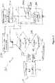
- Figure 2is block diagram of an exemplary pressure control system for use with the double-lumen endotracheal tube of Figure 1 .
- Figure 3is an example of connection of the double-lumen endotracheal tube of Figure 1 with the pressure control system of Figure 2 . Therefore, the following description will refer to Figures 2 and 3 concurrently.
- One inspiratory air source 100is connected to an inspiratory line 101 and generates an air pressure, volume or flow to produce a target air flow through the inspiratory line 101.
- the inspiratory line 101is in turn connected to an inspiratory tube lumen 102 of the double-lumen endotracheal tube 103 that is inserted into the patient's trachea 112.
- the inspiratory tube lumen 102may be a single or multiple lumen.
- a second lumen of the double-lumen endotracheal tube 103is connected to an expiratory line 105 connected to a pressure controller 200.
- the pressure controller 200may include a pressure sensor 201 and a valve 202 connected to an exhaust 204.
- a similar system for regulating air flow through the expiratory tube lumen 104 and the expiratory line 105may be used instead of the controller 200 as shown.
- the pressure controller 200may be feedback operated to produce and maintain a given pressure in the expiratory tube lumen 104 and the expiratory line 105.
- the valve 202may be controlled by a physiological breathing signal 250 for synchronizing the air flow through the expiratory tube lumen 104 and the expiratory line 105 with this physiological breathing signal 250.
- the pressure controller 200operates in such a manner that the valve 202 restricts, but does not completely occlude the expiratory line 105 such that a minimum outward air flow remains present in the expiratory tube lumen 104 and the expiratory line 105 during the patient's inspiratory phase. Modulation of the restriction of the air flow through the expiratory tube lumen 104 allows adjustment of the pressure in the respiratory circuit of the mechanical ventilator to be proportional to the physiological breathing signal 250.
- a lowest pressure limitmay be manually set to ensure sufficient positive end-expiratory pressure (PEEP) to maintain lung recruitment during neural expiration.
- PEEPpositive end-expiratory pressure
- the inspiratory air source 100generates a target air flow through the inspiratory line 101 and the inspiratory tube lumen 102.
- the pressure controller 200regulates a pressure for controlling air flow escaping the trachea 112 and the patient's lungs 110 through the expiratory tube lumen 104 and the expiratory line 105; more specifically, the pressure controller uses the valve 202 to alter a resistance to air flow of the expiratory tube lumen 104 and expiratory line 105.
- the problem of limiting air flow resistance through the expiratory tube lumen 104 and the expiratory line 105is resolved by providing the expiratory tube lumen 104 with a diameter larger than that of the inspiratory tube lumen 102.
- the larger resistance to air flow of the smaller-diameter inspiratory tube lumen 102causes a larger pressure drop.
- the effect of this larger pressure dropis compensated for by using the inspiratory air source 100 to generate a target air flow through the inspiratory tube lumen 102.
- a feedback system 300 between the pressure controller 200 and the inspiratory air source 100ensures that the target air flow through the inspiratory line 101 and inspiratory tube lumen 102 is adjusted to generate a preset target pressure in the trachea 112, the expiratory tube lumen 104 and the expiratory line 105.
- the feedback system 300comprises a first comparator 301 and an optional second comparator used as a minimum flow detector 302.
- the comparator 301may receive a target pressure signal from a target pressure adjuster 270.
- the target pressure adjuster 270is responsive to the physiological breathing signal 250 to adjust the level of a target pressure.
- the physiological breathing signal 250is a physiological signal as defined hereinabove. It may be reliably obtained as a measure of the electrical activation of the patient's diaphragm (EAdi), obtained for example using a method as described in US patents No. 5,671,752 , 5,820,560 , 6,588,423 and 6,901,286 .
- the physiological breathing signal 250may alternatively take the form of an electromyogram (EMG) signal obtained at the level of the alea of the nose (EMG-AN) of the patient, or at the thorax level (EMG-THO) of the patient.
- EMGelectromyogram
- Biometric signals from the phrenical nerve of the patient, surface EMG, or measures of chest wall movements of the patientmay also be used.
- any other suitable physiological breathing signal 250 indicative of inspiratory effort including onset detection of the inspiratory effort, before the generation of inspiratory flow occursmay be used.
- the target pressure adjuster 270may increase the level of the target pressure when the level of the physiological breathing signal 250 increases, indicating an increase of the patient's inspiratory effort.
- the adjuster 270may decrease the level of the target pressure when the level of the physiological breathing signal 250 decreases, indicating a decrease of the patient's inspiratory effort.
- the target pressuremay be adjusted by the target pressure adjuster 270 in proportion to the level of patient's inspiratory activity as indicated by the level of the physiological breathing signal 250 or in any other manner beneficial to patient's inspiratory assist.
- the target pressuremay further be set to ensure sufficient positive end-expiratory pressure (PEEP).
- PEEPpositive end-expiratory pressure
- the target pressure adjuster 270may also be set at a single level independent of the physiological breathing signal 250.
- Operation of the pressure control system 300may be synchronized using the physiological breathing signal 250. More specifically, the valve 202 of the pressure controller 200 will partially close when the physiological breathing signal 250 indicates patient's inspiratory effort to allow the target air flow from the inspiratory line 101 and the inspiratory tube lumen 102 to build up a pressure in the endotracheal tube 103, the expiratory tube lumen 104 and the expiratory line 105 in order to assist inspiration of the patient. The valve 202 is partially closed to maintain a minimum air flow through the expiratory tube lumen 104 and the expiratory line 105 to contribute to, if not completely eliminate, substantially reduce ventilatory circuit dead space and anatomical dead space, and ensure continuous washing out of CO 2 .
- the valve 202When the physiological breathing signal 250 no longer indicates inspiratory effort of the patient, the valve 202 is opened to an extent that allows the patient to expire through the double-lumen endotracheal tube 103, the expiratory tube lumen 104, the expiratory line 105, the valve 202 and the exhaust 204 while maintaining a certain level of expiratory pressure to prevent, for example, collapse of the lungs.
- a gain adjuster 260may alter the physiological breathing signal 250 to adjust the level of the pressure in the trachea 112, expiratory tube lumen 104 and expiratory line 105, and thereby adjust the level of ventilatory assistance to the patient.
- the adjustable gain 260may be manually set by the medical personnel. Automatic adjustment of the gain 260 may also be contemplated, for example to obtain a target level of ventilatory assistance or physiological breathing signal 250.
- Oxygen from an oxygen source 356may be injected in the inspiratory line 101 through a gas mixer 350 to enrich the target air flow through the inspiratory line 101 and inspiratory tube lumen 102.
- a humidity sensor (hygrometer) 352may be used to detect humidity in the expiratory line 105 and, in response to the detected humidity, control a humidifier 354 connected to the gas mixer 350 to humidify, whenever needed, the target air flow through the inspiratory line 101 and the inspiratory tube lumen 102.
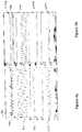
- Figure 4ais a graph of experimental recordings of physiological respiratory parameters illustrating operation of a conventional ventilator system.
- the graph of Figure 4amay be compared with the graph of Figure 4b , which is a graph of experimental recordings of physiological respiratory parameters using the double-lumen endotracheal tube and pressure control system of Figures 1 and 2 .
- Both Figures 4a and 4bshow recordings of air flow (402a, 402b), pressure (404a, 404b), and endtidal carbon dioxide (406a, 406b), measured in the expiratory line 105.
- Figures 4a and 4balso show recordings of diaphragm electrical activity (EAdi (408a, 408b)).
- the air flowis bidirectional (inspiration and expiration) during each breathing cycle. It may be observed that the flow (402a) is above a zero line (403a) during inspiration phases and below the zero line (403a) during expiration phases. This produces a dead space in a breathing tube (not shown) of the conventional ventilator system, corresponding to a volume of an expiratory line and tube lumen. Consequently, a volume of expired air from the lungs is returned to the lungs during the next inspiration.
- the graph of Figure 4billustrates recordings obtained using the double-lumen endotracheal tube 103 and pressure control system 300 of Figures 1 and 2 , wherein no air from the expiratory tube lumen 104 and the expiratory line 105 is returned to the patient's lungs 110.
- the air flow (402b)is unidirectional from the patient's lungs 110 towards the atmosphere and constantly remains below a zero line (403b). No volume of expired air from the patient's lungs 110 is returned to the lungs during the next inspiration.
- a comparison of the graphs of Figures 4a and 4bshows that the double-lumen endotracheal tube 103 and pressure control system 300 of Figures 1 and 2 may unload the patient's respiratory muscles by delivering ventilatory assist that is synchronized to the neural inspiratory effort (EAdi (408b)) both in terms of timing and pressure generation. Moreover, dead space may be minimized, and the metabolic load may be reduced (lower ETCO2, 406b) thereby further reducing respiratory drive (EAdi (408b)).
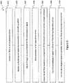
- FIG. 5is a flow chart of exemplary steps of a ventilatory assist method, capable of reducing neural inspiratory drive of a patient. Steps of a sequence 500 may be applied to a ventilatory assist system disclosed in the foregoing description given in relation to Figures 1 , 2 and 3 .
- an air flowis supplied in the inspiration tube lumen 102 of the tube 103 connected to the patient's airways.
- control of the air flow in an expiratory tube lumen 102 of the tube 103 connected to the patient's airwayis made in operation 530.
- the control made in operation 530is such that during the patient's inspiratory phase, the air flow through the expiratory tube lumen 104 connected to the patient's airways is partially restricted. In contrast, during the patient's expiratory phase, the air flow is unrestricted to allow expiratory flow from the patient's trachea 112 to evacuate through the endotracheal tube 103, the expiratory tube lumen 104, and thereby through the expiratory line 105.
- a result of the control made in operation 530is that during both the patient's inspiration and expiration phases, a unidirectional air flow is produced through the inspiratory tube lumen 102 and the expiratory tube lumen 104 to prevent air expired by the patient from being breathed again.
- Control of the air flow made in operation 530may for example be made by actuating the valve 202 of Figure 2 .
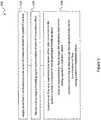
- Figure 6is a flow chart of other aspects of the ventilatory assist method of Figure 5 . It should be understood that the operations of the sequence 600 of Figure 6 may also be applied in a ventilatory assist system as described in connection with the description of Figures 1 , 2 and 3 . More specifically, the sequence 600 comprises:
- patient-synchronized ventilatory assistmay be customized to offer valuable solutions to existing needs and problems of ventilatory assist systems.
- the components, process steps, and/or signal structures described hereinmay be implemented using various types of operating systems, computing platforms, network devices, computer programs, and/or general purpose machines.
- devices of a less general purpose naturesuch as hardwired devices, field programmable gate arrays (FPGAs), application specific integrated circuits (ASICs), or the like, may also be used.
- FPGAsfield programmable gate arrays
- ASICsapplication specific integrated circuits
- Systems and modules described hereinmay comprise software, firmware, hardware, or any combination(s) of software, firmware, or hardware suitable for the purposes described herein.
- Software and other modulesmay reside on servers, workstations, personal computers, computerized tablets, personal digital assistants (PDA), and other devices suitable for the purposes described herein.
- Software and other modulesmay be accessible via local memory, via a network, via a browser or other application or via other means suitable for the purposes described herein.
- Data structures described hereinmay comprise computer files, variables, programming arrays, programming structures, or any electronic information storage schemes or not claimed methods, or any combinations thereof, suitable for the purposes described herein.
Landscapes
- Health & Medical Sciences (AREA)
- Life Sciences & Earth Sciences (AREA)
- Pulmonology (AREA)
- Veterinary Medicine (AREA)
- General Health & Medical Sciences (AREA)
- Animal Behavior & Ethology (AREA)
- Public Health (AREA)
- Engineering & Computer Science (AREA)
- Biomedical Technology (AREA)
- Heart & Thoracic Surgery (AREA)
- Anesthesiology (AREA)
- Emergency Medicine (AREA)
- Hematology (AREA)
- Biophysics (AREA)
- Surgery (AREA)
- Molecular Biology (AREA)
- Medical Informatics (AREA)
- Pathology (AREA)
- Physics & Mathematics (AREA)
- Physiology (AREA)
- Measurement Of The Respiration, Hearing Ability, Form, And Blood Characteristics Of Living Organisms (AREA)
Description
- The present disclosure relates to the field of ventilatory assist systems. More specifically, the present disclosure relates to a method and a system for patient-synchronized ventilatory assist with endotracheal throughflow.
- A recurring problem in patients with impaired function of the respiratory system is that the volume of air-exchanging lung parenchyma is reduced. This may be due to either edema, lung collapse and/or other factors. If a volume of air-transporting parenchyma/airways, comprising for example the main bronchi, trachea, and upper airways is maintained, the volume of air-exchanging parenchyma decreases relative to that of the air-transporting parenchyma/airways. In situations of increased need for CO2 removal, a ventilatory contribution may be hampered if a dead space, or dead volume, in an air-transporting parenchyma/airways and in a respiratory circuit for a mechanical ventilator, becomes abnormally large relative to a proportion of the lungs with intact air-exchanging parenchyma. Consequently, CO2 removal is hampered and arterial CO2 (PaCO2) may increase. This causes the tidal volume and ventilation to increase in order to maintain a tolerable level of arterial pressure (PaCO2).
- Until today, efforts have been made to minimize dead space, or dead volume, introduced in the respiratory circuit of mechanical ventilators. However actual tubes, for example endotracheal tubes, and other devices of conventional mechanical ventilators used to administer respiratory assist to a patient use single lumen designs and contribute to dead space ventilation. For that reason, CO2 removal cannot be optimized.
- Previous attempts to improve CO2 removal from endotracheal tubes include multi-lumen designs aimed at introducing an air flow through a side lumen to eliminate CO2 from a main lumen. An example of such design may be found in
U.S. Patent No. 5,291,882 . The proposed approach, which uses parallel lumens, does not eliminate completely the volume of air re-breathed by the patient during inspiration. Thus the proposed approach reduces, but does not optimize the CO2 removal and minimize the CO2 rebreathing problem. Moreover, problems of dynamic hyperinflation due to constant inspiratory flow has also complicated this approach. Other approaches using tube lumens with valve functions may increase risk of occlusion. - Other examples of prior art systems are disclosed in
US 2004/221854 A1 ,US 5 820 560 A andUS 5 429 123 A . - Therefore, there is a need for improvements leading to further reduction or elimination of dead space induced by the respiratory circuit of a mechanical ventilator.
- According to the present disclosure, there is provided a patient-synchronized ventilatory assist system. The ventilatory assist system comprises a tube for connection to a patient's airway, an inspiratory tube lumen connected to the tube, an expiratory tube lumen connected to the tube, an inspiratory air source connected to the inspiration tube lumen, and a controller of the pressure in the expiratory tube lumen. The pressure controller is responsive to a physiological breathing signal representative of patient's inspiratory effort. Based on the physiological breathing signal, the pressure controller allows an unrestricted air flow through the expiratory tube lumen during a patient's expiration phase and partially restricts the air flow through the expiratory tube lumen to a minimum air flow during a patient's inspiration phase. During both the patient's inspiration and expiration phases, a unidirectional air flow is produced through the inspiratory tube lumen and the expiratory tube lumen to prevent air expired by the patient from being breathed again.
- Further, there is disclosed a patient-synchronized ventilatory assist method. The method comprises supplying an air flow in an inspiratory tube lumen of a tube connected to a patient's airway and, in response to a physiological breathing signal representative of patient's inspiratory effort, controlling an air flow in an expiratory tube lumen of the tube connected to the patient's airway. Controlling the air flow allows an unrestricted air flow through the expiratory tube lumen during a patient's expiration phase. Controlling the air flow also partially restricts the air flow through the expiratory tube lumen to a minimum air flow during a patient's inspiration phase. During both the patient's inspiration and expiration phases, a unidirectional air flow is produced through the inspiratory tube lumen and the expiratory tube lumen to prevent air expired by the patient from being breathed again.
- The problem of the prior arts systems are solved with the features of claim 1.
- The foregoing and other features will become more apparent upon reading of the following non-restrictive description of illustrative embodiments thereof, given by way of example only with reference to the accompanying drawings.
- Embodiments of the disclosure will be described by way of example only with reference to the accompanying drawings, in which:
Figure 1 is a side cross sectional, partial view of an example of double-lumen endotracheal tube showing intratracheal pulmonary ventilation;Figure 2 is block diagram of an exemplary pressure control system for use with the double-lumen endotracheal tube ofFigure 1 ;Figure 3 is an example of connection of the double-lumen endotracheal tube ofFigure 1 with the pressure control system ofFigure 2 ;Figure 4a is a graph of experimental recordings of physiological respiratory parameters illustrating operation of a conventional ventilator system;Figure 4b is a graph of experimental recordings of physiological respiratory parameters using the double-lumen endotracheal tube and pressure control system ofFigures 1 and2 ;Figure 5 is a flow chart of exemplary steps of a ventilatory assist method, capable of reducing neural inspiratory drive of a patient; andFigure 6 is a flow chart of other aspects of the ventilatory assist method ofFigure 5 .- Various aspects of the present disclosure generally address one or more of the problems related to the presence of dead space induced by respiratory circuits of mechanical ventilators. The present disclosure also relates to a ventilatory assist system including a feature of reduction of anatomical dead space in a patient's airways.
- The following terminology is used throughout the present disclosure:
Ventilatory assist system: Apparatus adapted for medical use for assisting a patient in need of respiratory support. Airway: Of a patient, lungs, bronchi, trachea, pharynx, nose and mouth, through which air is breathed. Air: Any gas composition suitable for use in a ventilatory assist system. In the context of the present disclosure, the term "air" may refer to natural air, pure oxygen, natural air enriched with added oxygen, oxygen mixed with another gases such as water vapor, or any combination thereof. This term may also refer to air expelled from a patient's lungs, for example natural air containing additional CO2 and humidity. Lumen: A bore of a tube, for example a respiratory tube. A given tube may comprise a plurality of lumens. Physiological signal: A measurable biometric quantity capable of being transmitted, for example as an electrical signal. such as the physiological breathing signal, generated by respiratory muscles. Inspiratory effort: Voluntary or involuntary exertion of a breathing patient. This may be quantified as a neural measure. Restricted/unrestricted: In the context of the present disclosure, an air flow present in a tube, lumen, or like conduit may be subject to a variable resistance, or restriction. It is well-known to those skilled in the art of fluid mechanics that any conduit will apply at least a minimum resistance to a flow. The terms "unrestricted" and "restricted" should be understood as relative terms expressing, respectively, a lower and a higher resistance to an air flow. Minimum air flow: A partially restricted, non-zero air flow. Endotracheal: Of a tube adapted for placement into a patient's trachea. Synchrony: Time-wise correspondence between events. - A result of the reduction and elimination of dead space induced by the respiratory circuit of a mechanical ventilator is a reduction of respiratory drive, tidal volumes and ventilation, for example in critically ill patients. In this manner, mechanical ventilation may be used to efficiently unload the patient's respiratory system and respiratory muscles. Also, ventilatory CO2 removal is optimized due to the reduction of dead space, limiting CO2 rebreathing, which in turn reduces metabolic load.
- The ventilatory assist system introduced herein supply ventilatory assist during inspiration via an endotracheal tube structured for delivering a separate, unidirectional inspiratory air flow into the patient's trachea via a first inspiratory tube lumen and a separate, unidirectional expiratory air flow from the patient's trachea through a second expiratory tube lumen. Also, a unidirectional flow of air is produced and maintained through the inspiratory tube lumen and the expiratory tube lumen; in this manner, ventilatory circuit dead space is eliminated, anatomical dead space is substantially reduced and washing out of CO2 is optimized.
- In an aspect, mechanical ventilation may be synchronized with patient's effort to breathe. For example, a physiological breathing signal is used to regulate the ventilatory assist in synchrony with patient's neural inspiration effort, thereby unloading and compensating for weak respiratory muscles.
- Turning now to the appended drawings,
Figure 1 is a side cross sectional, partial view of an example of double-lumen endotracheal tube showing intratracheal pulmonary ventilation. A double-lumenendotracheal tube 103 shown onFigure 1 forms part of a mechanical ventilator system for delivering air to thelungs 110 of a patient via thetrachea 112. Schematically shown inFigure 1 are an inspiratory flow indirection 106 toward the patient'slungs 110 and an expiratory flow indirection 107 away from the patient'slungs 110, through the double-lumenendotracheal tube 103 inserted into thetrachea 112.Direction 106 is shown as a narrow arrow whiledirection 107 is shown as a thick arrow; this should be understood as a schematic manner of illustrating that the inspiratory flow indirection 106 originates from a smaller-diameter inspiratory tube lumen (also shown inFigure 3 ) while the expiratory flow indirection 107 is directed through a larger-diameter expiratory tube lumen (also shown inFigure 3 ). Figure 2 is block diagram of an exemplary pressure control system for use with the double-lumen endotracheal tube ofFigure 1 .Figure 3 is an example of connection of the double-lumen endotracheal tube ofFigure 1 with the pressure control system ofFigure 2 . Therefore, the following description will refer toFigures 2 and3 concurrently.- One
inspiratory air source 100 is connected to aninspiratory line 101 and generates an air pressure, volume or flow to produce a target air flow through theinspiratory line 101. Theinspiratory line 101 is in turn connected to aninspiratory tube lumen 102 of the double-lumenendotracheal tube 103 that is inserted into the patient'strachea 112. Theinspiratory tube lumen 102 may be a single or multiple lumen. - A second lumen of the double-lumen
endotracheal tube 103, hereinafter referred to as anexpiratory tube lumen 104, is connected to anexpiratory line 105 connected to apressure controller 200. Thepressure controller 200 may include apressure sensor 201 and avalve 202 connected to an exhaust 204. A similar system for regulating air flow through theexpiratory tube lumen 104 and theexpiratory line 105 may be used instead of thecontroller 200 as shown. Thepressure controller 200 may be feedback operated to produce and maintain a given pressure in theexpiratory tube lumen 104 and theexpiratory line 105. As will be described in more detail in the following description, thevalve 202 may be controlled by aphysiological breathing signal 250 for synchronizing the air flow through theexpiratory tube lumen 104 and theexpiratory line 105 with thisphysiological breathing signal 250. Thepressure controller 200 operates in such a manner that thevalve 202 restricts, but does not completely occlude theexpiratory line 105 such that a minimum outward air flow remains present in theexpiratory tube lumen 104 and theexpiratory line 105 during the patient's inspiratory phase. Modulation of the restriction of the air flow through theexpiratory tube lumen 104 allows adjustment of the pressure in the respiratory circuit of the mechanical ventilator to be proportional to thephysiological breathing signal 250. A lowest pressure limit may be manually set to ensure sufficient positive end-expiratory pressure (PEEP) to maintain lung recruitment during neural expiration. - More specifically, the
inspiratory air source 100 generates a target air flow through theinspiratory line 101 and theinspiratory tube lumen 102. In turn, thepressure controller 200 regulates a pressure for controlling air flow escaping thetrachea 112 and the patient'slungs 110 through theexpiratory tube lumen 104 and theexpiratory line 105; more specifically, the pressure controller uses thevalve 202 to alter a resistance to air flow of theexpiratory tube lumen 104 andexpiratory line 105. - The problem of limiting air flow resistance through the
expiratory tube lumen 104 and theexpiratory line 105 is resolved by providing theexpiratory tube lumen 104 with a diameter larger than that of theinspiratory tube lumen 102. The larger resistance to air flow of the smaller-diameterinspiratory tube lumen 102 causes a larger pressure drop. However, the effect of this larger pressure drop is compensated for by using theinspiratory air source 100 to generate a target air flow through theinspiratory tube lumen 102. - A
feedback system 300 between thepressure controller 200 and theinspiratory air source 100 ensures that the target air flow through theinspiratory line 101 andinspiratory tube lumen 102 is adjusted to generate a preset target pressure in thetrachea 112, theexpiratory tube lumen 104 and theexpiratory line 105. Thefeedback system 300 comprises afirst comparator 301 and an optional second comparator used as aminimum flow detector 302. Thecomparator 301 may receive a target pressure signal from atarget pressure adjuster 270. - The
target pressure adjuster 270 is responsive to thephysiological breathing signal 250 to adjust the level of a target pressure. Thephysiological breathing signal 250 is a physiological signal as defined hereinabove. It may be reliably obtained as a measure of the electrical activation of the patient's diaphragm (EAdi), obtained for example using a method as described inUS patents No. 5,671,752 ,5,820,560 ,6,588,423 and6,901,286 . Thephysiological breathing signal 250 may alternatively take the form of an electromyogram (EMG) signal obtained at the level of the alea of the nose (EMG-AN) of the patient, or at the thorax level (EMG-THO) of the patient. Biometric signals from the phrenical nerve of the patient, surface EMG, or measures of chest wall movements of the patient may also be used. Of course any other suitablephysiological breathing signal 250 indicative of inspiratory effort including onset detection of the inspiratory effort, before the generation of inspiratory flow occurs, may be used. For example, thetarget pressure adjuster 270 may increase the level of the target pressure when the level of thephysiological breathing signal 250 increases, indicating an increase of the patient's inspiratory effort. In the same manner, theadjuster 270 may decrease the level of the target pressure when the level of thephysiological breathing signal 250 decreases, indicating a decrease of the patient's inspiratory effort. In fact, the target pressure may be adjusted by thetarget pressure adjuster 270 in proportion to the level of patient's inspiratory activity as indicated by the level of thephysiological breathing signal 250 or in any other manner beneficial to patient's inspiratory assist. In an embodiment, the target pressure may further be set to ensure sufficient positive end-expiratory pressure (PEEP). Obviously, thetarget pressure adjuster 270 may also be set at a single level independent of thephysiological breathing signal 250. - Operation of the
feedback system 300 follows the following rules: - The target air flow through the
inspiratory line 101 andinspiratory tube lumen 102 is increased when thecomparator 301 detects that the pressure reading 203 from thepressure sensor 201 of thepressure controller 200, indicative of the pressure in thetrachea 112,expiratory tube lumen 104 andexpiratory line 105 during the patient's inspiration phase is lower than a target pressure, which may be set according to a target pressure signal from thetarget pressure adjuster 270. - The target air flow through the
inspiratory line 101 andinspiratory tube lumen 102 is decreased when thecomparator 301 detects that the pressure reading 203 from thepressure sensor 201 of thepressure controller 200, indicative of the pressure in thetrachea 112,expiratory tube lumen 104 andexpiratory line 105 during the patient's inspiration phase is higher than the target pressure from thetarget pressure adjuster 270, and also if it is higher than the manually set PEEP level. Before decreasing the target air flow through theinspiratory line 101 andinspiratory tube lumen 102, theminimum flow detector 302 ensures that theinspiratory air source 100 maintains a target air flow, through theinspiratory line 101 andinspiratory tube lumen 102, that is at least equal to or higher than a minimum value. If not, the target air flow through theinspiratory line 101 andinspiratory tube lumen 102 is maintained. The minimum value used in theminimum flow detector 302 for the target air flow is selected to be sufficient to ensure continuous washing out of CO2. - Operation of the
pressure control system 300 may be synchronized using thephysiological breathing signal 250. More specifically, thevalve 202 of thepressure controller 200 will partially close when thephysiological breathing signal 250 indicates patient's inspiratory effort to allow the target air flow from theinspiratory line 101 and theinspiratory tube lumen 102 to build up a pressure in theendotracheal tube 103, theexpiratory tube lumen 104 and theexpiratory line 105 in order to assist inspiration of the patient. Thevalve 202 is partially closed to maintain a minimum air flow through theexpiratory tube lumen 104 and theexpiratory line 105 to contribute to, if not completely eliminate, substantially reduce ventilatory circuit dead space and anatomical dead space, and ensure continuous washing out of CO2. When thephysiological breathing signal 250 no longer indicates inspiratory effort of the patient, thevalve 202 is opened to an extent that allows the patient to expire through the double-lumenendotracheal tube 103, theexpiratory tube lumen 104, theexpiratory line 105, thevalve 202 and the exhaust 204 while maintaining a certain level of expiratory pressure to prevent, for example, collapse of the lungs. - It should be understood that, during both the inspiration and expiration phases, a unidirectional air flow is produced through the
inspiratory line 101, theinspiratory tube lumen 102, theexpiratory tube lumen 104 and theexpiratory line 105 to prevent air expired by the patient to be breathed again. In this manner, ventilatory circuit dead space and anatomical dead space are, if not completely eliminated, substantially reduced and continuous washing out of CO2 is ensured. - In an embodiment, a
gain adjuster 260 may alter thephysiological breathing signal 250 to adjust the level of the pressure in thetrachea 112,expiratory tube lumen 104 andexpiratory line 105, and thereby adjust the level of ventilatory assistance to the patient. For example, theadjustable gain 260 may be manually set by the medical personnel. Automatic adjustment of thegain 260 may also be contemplated, for example to obtain a target level of ventilatory assistance orphysiological breathing signal 250. - Some options, amongst others, to deliver inspiratory assist to the patient are the following:
- A target pressure or volume may be supplied to the patient during inspiration.
- As explained in the foregoing description, the target pressure may be adjusted by the
target pressure adjuster 270 in proportion to the level of patient's inspiratory activity as indicated by the level of thephysiological breathing signal 250 or in any other manner beneficial to patient's inspiratory assist. - A mathematical model may be used for calculating a pressure loss within the
endotracheal tube 103 based on a known air flow resistance and the diameters of theendotracheal tube 103, theexpiratory tube lumen 104 and theexpiratory line 105, and on a measurement of the air flow through theseendotracheal tube 103, theexpiratory tube lumen 104 and theexpiratory line 105. The calculated pressure loss may then serve as the target pressure used by thecomparator 301. - Another option is to directly measure a pressure at the free, proximal end of the
endotracheal tube 103 inserted into the patient'strachea 112, near the tracheal bifurcation 150 (Figure 1 ), and use this pressure as the target pressure of thecomparator 301. - Oxygen from an
oxygen source 356 may be injected in theinspiratory line 101 through agas mixer 350 to enrich the target air flow through theinspiratory line 101 andinspiratory tube lumen 102. - To ensure adequate humidification, a humidity sensor (hygrometer) 352 may be used to detect humidity in the
expiratory line 105 and, in response to the detected humidity, control a humidifier 354 connected to thegas mixer 350 to humidify, whenever needed, the target air flow through theinspiratory line 101 and theinspiratory tube lumen 102. Figure 4a is a graph of experimental recordings of physiological respiratory parameters illustrating operation of a conventional ventilator system. The graph ofFigure 4a may be compared with the graph ofFigure 4b , which is a graph of experimental recordings of physiological respiratory parameters using the double-lumen endotracheal tube and pressure control system ofFigures 1 and2 . BothFigures 4a and 4b show recordings of air flow (402a, 402b), pressure (404a, 404b), and endtidal carbon dioxide (406a, 406b), measured in theexpiratory line 105.Figures 4a and 4b also show recordings of diaphragm electrical activity (EAdi (408a, 408b)).- In the case of
Figure 4a , the air flow is bidirectional (inspiration and expiration) during each breathing cycle. It may be observed that the flow (402a) is above a zero line (403a) during inspiration phases and below the zero line (403a) during expiration phases. This produces a dead space in a breathing tube (not shown) of the conventional ventilator system, corresponding to a volume of an expiratory line and tube lumen. Consequently, a volume of expired air from the lungs is returned to the lungs during the next inspiration. - The graph of
Figure 4b illustrates recordings obtained using the double-lumenendotracheal tube 103 andpressure control system 300 ofFigures 1 and2 , wherein no air from theexpiratory tube lumen 104 and theexpiratory line 105 is returned to the patient'slungs 110. The air flow (402b) is unidirectional from the patient'slungs 110 towards the atmosphere and constantly remains below a zero line (403b). No volume of expired air from the patient'slungs 110 is returned to the lungs during the next inspiration. - It may be observed that, in
Figure 4b , the endtidal carbon dioxide (406b) level is markedly reduced, compared to the corresponding level (406a) ofFigure 4a , during respiratory assist with the double-lumenendotracheal tube 103 andpressure control system 300 ofFigures 1 and2 . It may also be observed that the diaphragm electrical activity (408b) and delivered pressure (404b) are reduced inFigure 4b , compared to corresponding readings (408a, 404a) ofFigure 4a , although the ventilator system settings are the same. It may further be observed that generation of the pressure (404b) is synchronized with the diaphragm electrical activity (408b). - A comparison of the graphs of
Figures 4a and 4b shows that the double-lumenendotracheal tube 103 andpressure control system 300 ofFigures 1 and2 may unload the patient's respiratory muscles by delivering ventilatory assist that is synchronized to the neural inspiratory effort (EAdi (408b)) both in terms of timing and pressure generation. Moreover, dead space may be minimized, and the metabolic load may be reduced (lower ETCO2, 406b) thereby further reducing respiratory drive (EAdi (408b)). Figure 5 is a flow chart of exemplary steps of a ventilatory assist method, capable of reducing neural inspiratory drive of a patient. Steps of asequence 500 may be applied to a ventilatory assist system disclosed in the foregoing description given in relation toFigures 1 ,2 and3 . Inoperation 510, an air flow is supplied in theinspiration tube lumen 102 of thetube 103 connected to the patient's airways. In response to a physiological signal representative of the patient's inspiratory effort, received inoperation 520, control of the air flow in anexpiratory tube lumen 102 of thetube 103 connected to the patient's airway is made inoperation 530. The control made inoperation 530 is such that during the patient's inspiratory phase, the air flow through theexpiratory tube lumen 104 connected to the patient's airways is partially restricted. In contrast, during the patient's expiratory phase, the air flow is unrestricted to allow expiratory flow from the patient'strachea 112 to evacuate through theendotracheal tube 103, theexpiratory tube lumen 104, and thereby through theexpiratory line 105.- A result of the control made in
operation 530 is that during both the patient's inspiration and expiration phases, a unidirectional air flow is produced through theinspiratory tube lumen 102 and theexpiratory tube lumen 104 to prevent air expired by the patient from being breathed again. - Control of the air flow made in
operation 530 may for example be made by actuating thevalve 202 ofFigure 2 . Figure 6 is a flow chart of other aspects of the ventilatory assist method ofFigure 5 . It should be understood that the operations of thesequence 600 ofFigure 6 may also be applied in a ventilatory assist system as described in connection with the description ofFigures 1 ,2 and3 . More specifically, thesequence 600 comprises:- Operation 610: A target air flow is produced by the
inspiratory air source 100 through theinspiratory tube lumen 101 and theinspiratory line 102. - Operation 620: The
physiological breathing signal 250 representative of inspiratory effort of the patient is received by thepressure control system 300. - Operation 630: The
target pressure adjuster 270 adjusts a target pressure in response to thephysiological breathing signal 250. - Operation 640: Pressure in the
endotracheal tube 103, theexpiratory tube lumen 104 and theexpiratory line 105 is sensed, or detected, throughpressure sensor 201. - Operation 650: The target air flow produced by the
inspiratory air source 100 in theinspiratory line 101 and theinspiratory tube lumen 102 is adjusted, or controlled, as a function of a comparison by thecomparator 301 between the pressure detected in theendotracheal tube 103, theexpiratory tube lumen 104 and theexpiratory line 105 and the target pressure from theadjuster 270. - Operation 660: The
physiological breathing signal 250 is used to control air flow through theexpiratory tube lumen 104 and theexpiratory line 105 by controlling opening of thevalve 202, thereby altering a pressure in the double-lumenendotracheal tube 103, theexpiratory tube lumen 104 and theexpiratory line 105 in synchrony with the patient's inspiratory effort as indicated by thephysiological breathing signal 250. Inoperation 660, when thephysiological breathing signal 250 indicates an expiratory phase, thevalve 202 is opened to an extent to allow the patient to expire through the double-lumenendotracheal tube 103, theexpiratory tube lumen 104, theexpiratory line 105, thevalve 202 and the exhaust 204 while maintaining a certain level of expiratory pressure to prevent, for example, collapse of the lungs during that expiratory phase. - Operation 670: When the
physiological breathing signal 250 indicates an inspiratory phase, thevalve 202 will partially close to increase resistance to air flow through theexpiratory tube lumen 104 and theexpiratory line 105 to allow the target air flow from theinspiratory line 101 and theinspiratory tube lumen 102 to build up a pressure in theendotracheal tube 103, theexpiratory tube lumen 104 and theexpiratory line 105 in order to assist inspiration of the patient. Thevalve 202 is partially closed to maintain a minimum air flow through theendotracheal tube 103, theexpiratory tube lumen 104 and theexpiratory line 105 to contribute to eliminate ventilatory circuit dead space and substantially reduce anatomical dead space, and ensure continuous washing out of CO2. - Those of ordinary skill in the art will realize that the description of the devices and not claimed methods for patient-synchronized ventilatory assist are illustrative only and are not intended to be in any way limiting. Other embodiments will readily suggest themselves to such persons with ordinary skill in the art having the benefit of the present disclosure. Furthermore, the disclosed patient-synchronized ventilatory assist may be customized to offer valuable solutions to existing needs and problems of ventilatory assist systems.
- In the interest of clarity, not all of the routine features of the implementations of patient-synchronized ventilatory assist systems and not claimed methods are shown and described. It will, of course, be appreciated that in the development of any such actual implementation of the patient-synchronized ventilatory assist systems and methods, numerous implementation-specific decisions may need to be made in order to achieve the developer's specific goals, such as compliance with application-, system- and business-related constraints, and that these specific goals will vary from one implementation to another and from one developer to another. Moreover, it will be appreciated that a development effort might be complex and time-consuming, but would nevertheless be a routine undertaking of engineering for those of ordinary skill in the field of ventilatory assist systems having the benefit of the present disclosure.
- In accordance with the present disclosure, the components, process steps, and/or signal structures described herein may be implemented using various types of operating systems, computing platforms, network devices, computer programs, and/or general purpose machines. In addition, those of ordinary skill in the art will recognize that devices of a less general purpose nature, such as hardwired devices, field programmable gate arrays (FPGAs), application specific integrated circuits (ASICs), or the like, may also be used. Where a not claimed method comprising a series of process steps is implemented by a computer or a machine and those process steps may be stored as a series of instructions readable by the machine, they may be stored on a tangible medium.
- Systems and modules described herein may comprise software, firmware, hardware, or any combination(s) of software, firmware, or hardware suitable for the purposes described herein. Software and other modules may reside on servers, workstations, personal computers, computerized tablets, personal digital assistants (PDA), and other devices suitable for the purposes described herein. Software and other modules may be accessible via local memory, via a network, via a browser or other application or via other means suitable for the purposes described herein. Data structures described herein may comprise computer files, variables, programming arrays, programming structures, or any electronic information storage schemes or not claimed methods, or any combinations thereof, suitable for the purposes described herein.
- Although the present disclosure has been described hereinabove by way of non-restrictive, illustrative embodiments thereof, these embodiments may be modified at will within the scope of the appended claims without departing from the nature of the present disclosure.
Claims (16)
- A ventilatory assist system, comprising:a tube (103) for connection to an airway (112) of a patient;an inspiratory tube lumen (102) connected to the tube (103);an expiratory tube lumen (104) connected to the tube (103);one inspiratory air source (100) connected to the inspiratory tube lumen (102) and adapted to generate a target air flow through the inspiratory tube lumen (102); anda pressure controller (200) adapted to regulate a pressure in the expiratory tube lumen (104),characterized in that:the pressure controller (200) is responsive to a physiological breathing signal (250) representative of an inspiratory effort of the patient for allowing an expiratory air flow to pass without restriction through the expiratory tube lumen (104) during an expiration phase of the patient and for partially restricting the expiratory air flow through the expiratory tube lumen (104) to maintain a minimum of the expiratory air flow through the expiratory tube lumen (104) during an inspiration phase of the patient;wherein, during both the inspiration and expiration phases of the patient, a unidirectional flow of air is produced and maintained by the inspiratory air source (100) through the inspiratory tube lumen (102) and the expiratory tube lumen (104) to prevent air expired by the patient from being breathed again.
- The ventilatory assist system of claim 1, wherein the pressure controller (200) comprises a valve (202) controlled and synchronized using the physiological breathing signal (250).
- The ventilatory assist system of claim 2, wherein the valve (202) is for partially restricting the expiratory air flow through the expiratory tube lumen (104).
- The ventilatory assist system of claim 1, wherein the physiological breathing signal (250) is a measure of electrical activation of a diaphragm (EAdi) of the patient.
- The ventilatory assist system of claim 1, further comprising:a pressure sensor (201) for sensing a pressure in the expiratory tube lumen (104); anda feedback system (300) interposed between the pressure sensor (201) and the inspiratory air source (100).
- The ventilatory assist system of claim 5, wherein the feedback system (300) comprises a comparator (301) of the pressure sensed by the pressure sensor in the expiratory tube lumen (104) to a target pressure.
- The ventilatory assist system of claim 6, further comprising a target pressure adjuster (270) for setting the target pressure.
- The ventilatory assist system of claim 6, wherein the inspiratory air source (100) is for increasing the target air flow through the inspiratory tube lumen (102) based on a low pressure detection from the comparator (301).
- The ventilatory assist system of claim 5, wherein the feedback system (300) comprises a minimum flow detector (302) for maintaining at least the minimum of the expiratory air flow through the expiratory tube lumen (104).
- The ventilatory assist system of claim 9, wherein the inspiratory air source (100) is for maintaining at least the minimum of the expiratory air flow through the expiratory tube lumen (104) based on a signal from the minimum flow detector (302).
- The ventilatory assist system of claim 1, wherein the tube (103) is an endotracheal tube.
- The ventilatory assist system of claim 1, wherein the inspiratory tube lumen (102) is a smaller-diameter tube lumen and the expiratory tube lumen (104) is a larger-diameter tube lumen.
- The ventilatory assist system of claim 1, further comprising a gas mixer (350) connected to the inspiration tube lumen (102).
- The ventilatory assist system of claim 13, further comprising an oxygen source (356) connected to the gas mixer (350).
- The ventilatory assist system of claim 13, further comprising:a hygrometer (352) connected to the expiratory tube lumen (104); anda humidifier (354) controlled by the hygrometer (352) and connected to the gas mixer (350).
- The ventilatory assist system of claim 1, further comprising a gain adjuster (260) interposed between a source of the physiological breathing signal (250) and the pressure controller (200) for adjusting a level of ventilatory assistance to the patient.
Applications Claiming Priority (2)
| Application Number | Priority Date | Filing Date | Title |
|---|---|---|---|
| US35995110P | 2010-06-30 | 2010-06-30 | |
| PCT/CA2011/000765WO2012000096A1 (en) | 2010-06-30 | 2011-06-29 | Method and system for patient-synchronized ventilatory assist with endotracheal through-flow |
Publications (3)
| Publication Number | Publication Date |
|---|---|
| EP2588177A1 EP2588177A1 (en) | 2013-05-08 |
| EP2588177A4 EP2588177A4 (en) | 2016-11-30 |
| EP2588177B1true EP2588177B1 (en) | 2020-01-01 |
Family
ID=45401260
Family Applications (1)
| Application Number | Title | Priority Date | Filing Date |
|---|---|---|---|
| EP11800020.7AActiveEP2588177B1 (en) | 2010-06-30 | 2011-06-29 | System for patient-synchronized ventilatory assist with endotracheal through-flow |
Country Status (4)
| Country | Link |
|---|---|
| US (1) | US9968750B2 (en) |
| EP (1) | EP2588177B1 (en) |
| CN (1) | CN103079621B (en) |
| WO (1) | WO2012000096A1 (en) |
Families Citing this family (12)
| Publication number | Priority date | Publication date | Assignee | Title |
|---|---|---|---|---|
| EP3086831B1 (en) | 2013-12-27 | 2020-09-23 | St. Michael's Hospital | System for providing ventilatory assist to a patient |
| US9950129B2 (en) | 2014-10-27 | 2018-04-24 | Covidien Lp | Ventilation triggering using change-point detection |
| US10799658B2 (en)* | 2015-03-26 | 2020-10-13 | Maquet Critical Care Ab | Control of mechanical ventilation based on laryngopharyngeal muscle activity |
| CN105225590B (en)* | 2015-09-01 | 2018-06-08 | 天津市海河医院 | Air source pumping device for establishing respiratory failure animal model and implementation method thereof |
| DE102016112822A1 (en)* | 2016-07-13 | 2018-01-18 | Fraunhofer-Gesellschaft zur Förderung der angewandten Forschung e.V. | Breath-controlled application of powdered aerosol during ventilation or respiratory support of a patient |
| WO2019222258A1 (en) | 2018-05-14 | 2019-11-21 | Covidien Lp | Systems and methods for respiratory effort detection utilizing signal distortion |
| US20210308401A1 (en)* | 2018-08-24 | 2021-10-07 | Imtmedical Ag | Method for operating an actuator in a medical apparatus, and device therefor |
| WO2020064784A1 (en)* | 2018-09-28 | 2020-04-02 | Koninklijke Philips N.V. | Humidifier with ingress protection for use in cpap therapy |
| US11752287B2 (en) | 2018-10-03 | 2023-09-12 | Covidien Lp | Systems and methods for automatic cycling or cycling detection |
| CN110237394A (en)* | 2019-06-17 | 2019-09-17 | 吉林大学第一医院 | Synchronous valve device for ventilator |
| US11826507B2 (en) | 2019-08-06 | 2023-11-28 | SharpMed, LLC. | Endotracheal tube cap with pressure relief valve |
| US11285286B1 (en)* | 2020-09-08 | 2022-03-29 | Lukasz R. Kiljanek | Ventilator system with multiple airflow control lumens |
Family Cites Families (47)
| Publication number | Priority date | Publication date | Assignee | Title |
|---|---|---|---|---|
| US4245633A (en)* | 1979-01-31 | 1981-01-20 | Erceg Graham W | PEEP providing circuit for anesthesia systems |
| US5161525A (en)* | 1990-05-11 | 1992-11-10 | Puritan-Bennett Corporation | System and method for flow triggering of pressure supported ventilation |
| US5291882A (en) | 1992-05-11 | 1994-03-08 | Makhoul Imad R | Multi-lumen ITPV endotracheal tube |
| US5429123A (en) | 1993-12-15 | 1995-07-04 | Temple University - Of The Commonwealth System Of Higher Education | Process control and apparatus for ventilation procedures with helium and oxygen mixtures |
| US5823184A (en)* | 1994-04-18 | 1998-10-20 | Tyco International (Us) Inc. | Breathing circuit |
| US5540220A (en)* | 1994-12-08 | 1996-07-30 | Bear Medical Systems, Inc. | Pressure-limited, time-cycled pulmonary ventilation with volume-cycle override |
| US5820560A (en)* | 1995-03-31 | 1998-10-13 | Universite De Montreal | Inspiratory proportional pressure assist ventilation controlled by a diaphragm electromyographic signal |
| US5671752A (en)* | 1995-03-31 | 1997-09-30 | Universite De Montreal/The Royal Insitution For The Advancement Of Learning (Mcgill University) | Diaphragm electromyography analysis method and system |
| DE19516536C2 (en)* | 1995-05-05 | 1998-02-12 | Draegerwerk Ag | Ventilator |
| US5823186A (en)* | 1996-06-20 | 1998-10-20 | Dragerwerk Ag | Respirator |
| FI105162B (en)* | 1997-02-06 | 2000-06-30 | Instrumentarium Oy | Breathing intensifier and valve coupled to a channel of a breathing intensifier |
| CA2443306C (en)* | 1997-06-17 | 2005-11-22 | Fisher & Paykel Limited | Respiratory humidification system |
| US6588423B1 (en)* | 1998-02-27 | 2003-07-08 | Universite De Montreal | Method and device responsive to myoelectrical activity for triggering ventilatory support |
| US6102042A (en) | 1998-12-22 | 2000-08-15 | Respironics, Inc. | Insufflation system, attachment and method |
| US7431031B2 (en)* | 1998-12-22 | 2008-10-07 | Ric Investments, Llc | Insufflation system and method |
| CA2276962A1 (en)* | 1999-07-07 | 2001-01-07 | Universite De Montreal | Electromyogram signal analysis method and system for use with electrode array |
| SE0002449D0 (en)* | 2000-06-29 | 2000-06-29 | Siemens Elema Ab | Method and arrangement for evaluating effective flow resistance of a patient breathing circuit |
| US6349724B1 (en) | 2000-07-05 | 2002-02-26 | Compumedics Sleep Pty. Ltd. | Dual-pressure blower for positive air pressure device |
| US6626175B2 (en)* | 2000-10-06 | 2003-09-30 | Respironics, Inc. | Medical ventilator triggering and cycling method and mechanism |
| US6622726B1 (en)* | 2000-10-17 | 2003-09-23 | Newport Medical Instruments, Inc. | Breathing apparatus and method |
| DE10118605C1 (en)* | 2001-04-12 | 2002-06-13 | Ruesch Willy Gmbh | Breathing tube, for selective endotracheal/esophagus-blocked breathing, where the axial opening of a first lumen is located directly after a second inflatable balloon, so in the vicinity the first balloon, the tube has a single lumen |
| DE10123278C1 (en)* | 2001-05-10 | 2002-06-13 | Univ Hamburg | Breathing device used in intensive care or during anesthesia comprises a respirator, an outlet, an inhalation tube, a twin-channel endotracheal tube, flow meters, pressure meters, and an evaluation device |
| WO2003026721A2 (en)* | 2001-09-24 | 2003-04-03 | Fukunaga Atsuo F | Breathing circuits having unconventional respiratory conduits and systems and methods for optimising utilisation of fresh gases |
| US7478634B2 (en)* | 2002-09-17 | 2009-01-20 | Jam Mohammad R | Respiratory booster machine and method for enhancing ventilation |
| JP2006518617A (en)* | 2003-02-18 | 2006-08-17 | フィッシャー,ジョセフ | Breathing circuit for easier measurement of cardiac output during controlled and spontaneous ventilation |
| WO2004073482A2 (en)* | 2003-02-19 | 2004-09-02 | Joseph Fisher | Method of measuring cardiac related parameters non-invasively via the lung during spontaneous and controlled ventilation |
| DE10319384A1 (en)* | 2003-04-30 | 2004-11-18 | Universität Hamburg | Ventilation device with a double-lumen endotracheal tube |
| US7007691B2 (en)* | 2003-05-13 | 2006-03-07 | Roger Daugherty | Apparatus and method for humidification of inspired gases |
| US8118024B2 (en)* | 2003-08-04 | 2012-02-21 | Carefusion 203, Inc. | Mechanical ventilation system utilizing bias valve |
| US7178521B2 (en)* | 2004-01-09 | 2007-02-20 | King Systems Corporation | Adjustable length breathing circuit |
| EP1715787A4 (en)* | 2004-02-18 | 2009-04-08 | Maquet Critical Care Ab | Method and device using myoelectrical activity for optimizing a patient's ventilatory assist |
| US20070068530A1 (en) | 2004-11-19 | 2007-03-29 | Pacey John A | Secretion clearing ventilation catheter and airway management system |
| CN101203260B (en)* | 2005-06-09 | 2010-12-22 | 马奎特紧急护理公司 | a ventilator |
| US7422015B2 (en)* | 2005-11-22 | 2008-09-09 | The General Electric Company | Arrangement and method for detecting spontaneous respiratory effort of a patient |
| US7617824B2 (en)* | 2005-12-08 | 2009-11-17 | Ric Investments, Llc | Ventilator adaptable for use with either a dual-limb circuit or a single-limb circuit |
| US8459262B2 (en)* | 2005-12-21 | 2013-06-11 | Maquet Critical Care Ab | Manual ventilation with electronically controlled APL valve |
| US20070295402A1 (en)* | 2006-06-21 | 2007-12-27 | General Electric Company | Pressurized gas supply and control system for actuation of active seals in turbomachinery |
| US7997272B2 (en)* | 2006-09-11 | 2011-08-16 | Ric Investments, Llc. | Ventilating apparatus and method enabling a patient to talk with or without a trachostomy tube check valve |
| US20100095961A1 (en)* | 2007-03-19 | 2010-04-22 | Carl Magnus Tornesel | Method and device for manual input and haptic output of patient critical operating parameters in a breathing apparatus |
| US8316849B2 (en)* | 2007-04-26 | 2012-11-27 | Buxco Electronics, Inc. | Integrated ventilator with calibration |
| CN101337101B (en) | 2007-07-06 | 2011-04-20 | 深圳迈瑞生物医疗电子股份有限公司 | Aerating system of anesthesia apparatus and respirator and pressure monitoring method |
| FR2921245B1 (en) | 2007-09-25 | 2009-12-04 | Univ Joseph Fourier | RESPIRATORY DIAGNOSTIC DEVICE |
| DE102007062214C5 (en) | 2007-12-21 | 2017-12-21 | Drägerwerk AG & Co. KGaA | Method for automatically controlling a respiratory system and associated ventilator |
| US8720441B2 (en)* | 2008-08-28 | 2014-05-13 | St. Michael's Hospital | Determining patient-ventilator breath contribution index in spontaneously breathing, mechanically ventilated patients |
| US8302602B2 (en)* | 2008-09-30 | 2012-11-06 | Nellcor Puritan Bennett Llc | Breathing assistance system with multiple pressure sensors |
| US8439036B2 (en)* | 2009-12-01 | 2013-05-14 | Covidien Lp | Exhalation valve assembly with integral flow sensor |
| EP3086831B1 (en)* | 2013-12-27 | 2020-09-23 | St. Michael's Hospital | System for providing ventilatory assist to a patient |
- 2011
- 2011-06-29EPEP11800020.7Apatent/EP2588177B1/enactiveActive
- 2011-06-29CNCN201180041915.1Apatent/CN103079621B/enactiveActive
- 2011-06-29WOPCT/CA2011/000765patent/WO2012000096A1/enactiveApplication Filing
- 2011-06-29USUS13/806,816patent/US9968750B2/enactiveActive
Non-Patent Citations (1)
| Title |
|---|
| None* |
Also Published As
| Publication number | Publication date |
|---|---|
| US9968750B2 (en) | 2018-05-15 |
| EP2588177A1 (en) | 2013-05-08 |
| US20140305434A1 (en) | 2014-10-16 |
| WO2012000096A1 (en) | 2012-01-05 |
| EP2588177A4 (en) | 2016-11-30 |
| CN103079621B (en) | 2015-09-16 |
| CN103079621A (en) | 2013-05-01 |
Similar Documents
| Publication | Publication Date | Title |
|---|---|---|
| EP2588177B1 (en) | System for patient-synchronized ventilatory assist with endotracheal through-flow | |
| US9022031B2 (en) | Using estimated carinal pressure for feedback control of carinal pressure during ventilation | |
| US9144658B2 (en) | Minimizing imposed expiratory resistance of mechanical ventilator by optimizing exhalation valve control | |
| US8776792B2 (en) | Methods and systems for volume-targeted minimum pressure-control ventilation | |
| US8408203B2 (en) | System and methods for ventilating a patient | |
| CN102369036B (en) | PEEP regulation of breathing equipment | |
| CN101448539B (en) | Ventilatory control system | |
| JP5507379B2 (en) | A device that achieves equilibrium against the inherent positive end expiratory pressure | |
| CN1886169B (en) | Method and device for system control of ventilation support in case of hypopnea | |
| US11116925B2 (en) | Device, method and system for providing ventilatory assist to a patient | |
| US20120298108A1 (en) | Automatically controlled ventilation system | |
| US20140261424A1 (en) | Methods and systems for phase shifted pressure ventilation | |
| US20100071697A1 (en) | Inversion-based feed-forward compensation of inspiratory trigger dynamics in medical ventilators | |
| US20100228142A1 (en) | Method and System for Determining Dynamically Respiratory Features in Spontaneoulsy Breathing Patients Receiving Mechanical Ventilatory Assist | |
| US20120325212A1 (en) | Method And Apparatus For Providing Positive Airway Pressure To A Patient | |
| JPH10505765A (en) | Pressure controlled breathing assist device | |
| AU2866500A (en) | Method and apparatus for controlling a medical ventilator | |
| EP2376158B1 (en) | Airway pressure release ventilation | |
| CN215961621U (en) | A tidal volume detection device for a bi-level ventilator | |
| US20200197642A1 (en) | Pressure support system and method of providing pressure support therapy to a patient | |
| CN110892486B (en) | Ventilator gas delivery inhalation via virtual pressure trigger mechanism | |
| Uchiyama et al. | A new expiratory support system for resolving air trapping in lungs during mechanical ventilation: a lung model study | |
| Shaikh et al. | Non-traditional Modes of Ventilation | |
| CN118488861A (en) | Ventilation device and ventilation control method and storage medium thereof |
Legal Events
| Date | Code | Title | Description |
|---|---|---|---|
| PUAI | Public reference made under article 153(3) epc to a published international application that has entered the european phase | Free format text:ORIGINAL CODE: 0009012 | |
| 17P | Request for examination filed | Effective date:20130117 | |
| AK | Designated contracting states | Kind code of ref document:A1 Designated state(s):AL AT BE BG CH CY CZ DE DK EE ES FI FR GB GR HR HU IE IS IT LI LT LU LV MC MK MT NL NO PL PT RO RS SE SI SK SM TR | |
| DAX | Request for extension of the european patent (deleted) | ||
| RA4 | Supplementary search report drawn up and despatched (corrected) | Effective date:20161027 | |
| RIC1 | Information provided on ipc code assigned before grant | Ipc:A61M 16/00 20060101AFI20161021BHEP Ipc:A61M 16/12 20060101ALI20161021BHEP Ipc:A61B 5/0488 20060101ALI20161021BHEP Ipc:A61M 16/16 20060101ALN20161021BHEP Ipc:A61M 16/04 20060101ALI20161021BHEP Ipc:A61M 16/20 20060101ALI20161021BHEP | |
| STAA | Information on the status of an ep patent application or granted ep patent | Free format text:STATUS: EXAMINATION IS IN PROGRESS | |
| 17Q | First examination report despatched | Effective date:20171222 | |
| RIC1 | Information provided on ipc code assigned before grant | Ipc:A61M 16/16 20060101ALN20190523BHEP Ipc:A61M 16/20 20060101ALI20190523BHEP Ipc:A61B 5/0488 20060101ALI20190523BHEP Ipc:A61M 16/12 20060101ALI20190523BHEP Ipc:A61B 5/00 20060101ALN20190523BHEP Ipc:A61M 16/00 20060101AFI20190523BHEP Ipc:A61M 16/04 20060101ALI20190523BHEP Ipc:A61B 5/087 20060101ALN20190523BHEP | |
| GRAP | Despatch of communication of intention to grant a patent | Free format text:ORIGINAL CODE: EPIDOSNIGR1 | |
| STAA | Information on the status of an ep patent application or granted ep patent | Free format text:STATUS: GRANT OF PATENT IS INTENDED | |
| INTG | Intention to grant announced | Effective date:20190729 | |
| GRAS | Grant fee paid | Free format text:ORIGINAL CODE: EPIDOSNIGR3 | |
| GRAA | (expected) grant | Free format text:ORIGINAL CODE: 0009210 | |
| STAA | Information on the status of an ep patent application or granted ep patent | Free format text:STATUS: THE PATENT HAS BEEN GRANTED | |
| AK | Designated contracting states | Kind code of ref document:B1 Designated state(s):AL AT BE BG CH CY CZ DE DK EE ES FI FR GB GR HR HU IE IS IT LI LT LU LV MC MK MT NL NO PL PT RO RS SE SI SK SM TR | |
| REG | Reference to a national code | Ref country code:GB Ref legal event code:FG4D | |
| REG | Reference to a national code | Ref country code:CH Ref legal event code:EP Ref country code:AT Ref legal event code:REF Ref document number:1218999 Country of ref document:AT Kind code of ref document:T Effective date:20200115 | |
| REG | Reference to a national code | Ref country code:DE Ref legal event code:R096 Ref document number:602011064384 Country of ref document:DE | |
| REG | Reference to a national code | Ref country code:IE Ref legal event code:FG4D | |
| REG | Reference to a national code | Ref country code:NL Ref legal event code:MP Effective date:20200101 | |
| REG | Reference to a national code | Ref country code:LT Ref legal event code:MG4D | |
| PG25 | Lapsed in a contracting state [announced via postgrant information from national office to epo] | Ref country code:RS Free format text:LAPSE BECAUSE OF FAILURE TO SUBMIT A TRANSLATION OF THE DESCRIPTION OR TO PAY THE FEE WITHIN THE PRESCRIBED TIME-LIMIT Effective date:20200101 Ref country code:NL Free format text:LAPSE BECAUSE OF FAILURE TO SUBMIT A TRANSLATION OF THE DESCRIPTION OR TO PAY THE FEE WITHIN THE PRESCRIBED TIME-LIMIT Effective date:20200101 Ref country code:LT Free format text:LAPSE BECAUSE OF FAILURE TO SUBMIT A TRANSLATION OF THE DESCRIPTION OR TO PAY THE FEE WITHIN THE PRESCRIBED TIME-LIMIT Effective date:20200101 Ref country code:NO Free format text:LAPSE BECAUSE OF FAILURE TO SUBMIT A TRANSLATION OF THE DESCRIPTION OR TO PAY THE FEE WITHIN THE PRESCRIBED TIME-LIMIT Effective date:20200401 Ref country code:FI Free format text:LAPSE BECAUSE OF FAILURE TO SUBMIT A TRANSLATION OF THE DESCRIPTION OR TO PAY THE FEE WITHIN THE PRESCRIBED TIME-LIMIT Effective date:20200101 Ref country code:CZ Free format text:LAPSE BECAUSE OF FAILURE TO SUBMIT A TRANSLATION OF THE DESCRIPTION OR TO PAY THE FEE WITHIN THE PRESCRIBED TIME-LIMIT Effective date:20200101 Ref country code:PT Free format text:LAPSE BECAUSE OF FAILURE TO SUBMIT A TRANSLATION OF THE DESCRIPTION OR TO PAY THE FEE WITHIN THE PRESCRIBED TIME-LIMIT Effective date:20200527 | |
| PG25 | Lapsed in a contracting state [announced via postgrant information from national office to epo] | Ref country code:SE Free format text:LAPSE BECAUSE OF FAILURE TO SUBMIT A TRANSLATION OF THE DESCRIPTION OR TO PAY THE FEE WITHIN THE PRESCRIBED TIME-LIMIT Effective date:20200101 Ref country code:HR Free format text:LAPSE BECAUSE OF FAILURE TO SUBMIT A TRANSLATION OF THE DESCRIPTION OR TO PAY THE FEE WITHIN THE PRESCRIBED TIME-LIMIT Effective date:20200101 Ref country code:GR Free format text:LAPSE BECAUSE OF FAILURE TO SUBMIT A TRANSLATION OF THE DESCRIPTION OR TO PAY THE FEE WITHIN THE PRESCRIBED TIME-LIMIT Effective date:20200402 Ref country code:IS Free format text:LAPSE BECAUSE OF FAILURE TO SUBMIT A TRANSLATION OF THE DESCRIPTION OR TO PAY THE FEE WITHIN THE PRESCRIBED TIME-LIMIT Effective date:20200501 Ref country code:LV Free format text:LAPSE BECAUSE OF FAILURE TO SUBMIT A TRANSLATION OF THE DESCRIPTION OR TO PAY THE FEE WITHIN THE PRESCRIBED TIME-LIMIT Effective date:20200101 Ref country code:BG Free format text:LAPSE BECAUSE OF FAILURE TO SUBMIT A TRANSLATION OF THE DESCRIPTION OR TO PAY THE FEE WITHIN THE PRESCRIBED TIME-LIMIT Effective date:20200401 | |
| REG | Reference to a national code | Ref country code:DE Ref legal event code:R097 Ref document number:602011064384 Country of ref document:DE | |
| PG25 | Lapsed in a contracting state [announced via postgrant information from national office to epo] | Ref country code:SK Free format text:LAPSE BECAUSE OF FAILURE TO SUBMIT A TRANSLATION OF THE DESCRIPTION OR TO PAY THE FEE WITHIN THE PRESCRIBED TIME-LIMIT Effective date:20200101 Ref country code:RO Free format text:LAPSE BECAUSE OF FAILURE TO SUBMIT A TRANSLATION OF THE DESCRIPTION OR TO PAY THE FEE WITHIN THE PRESCRIBED TIME-LIMIT Effective date:20200101 Ref country code:ES Free format text:LAPSE BECAUSE OF FAILURE TO SUBMIT A TRANSLATION OF THE DESCRIPTION OR TO PAY THE FEE WITHIN THE PRESCRIBED TIME-LIMIT Effective date:20200101 Ref country code:EE Free format text:LAPSE BECAUSE OF FAILURE TO SUBMIT A TRANSLATION OF THE DESCRIPTION OR TO PAY THE FEE WITHIN THE PRESCRIBED TIME-LIMIT Effective date:20200101 Ref country code:DK Free format text:LAPSE BECAUSE OF FAILURE TO SUBMIT A TRANSLATION OF THE DESCRIPTION OR TO PAY THE FEE WITHIN THE PRESCRIBED TIME-LIMIT Effective date:20200101 Ref country code:SM Free format text:LAPSE BECAUSE OF FAILURE TO SUBMIT A TRANSLATION OF THE DESCRIPTION OR TO PAY THE FEE WITHIN THE PRESCRIBED TIME-LIMIT Effective date:20200101 | |
| PLBE | No opposition filed within time limit | Free format text:ORIGINAL CODE: 0009261 | |
| STAA | Information on the status of an ep patent application or granted ep patent | Free format text:STATUS: NO OPPOSITION FILED WITHIN TIME LIMIT | |
| REG | Reference to a national code | Ref country code:AT Ref legal event code:MK05 Ref document number:1218999 Country of ref document:AT Kind code of ref document:T Effective date:20200101 | |
| 26N | No opposition filed | Effective date:20201002 | |
| PG25 | Lapsed in a contracting state [announced via postgrant information from national office to epo] | Ref country code:MC Free format text:LAPSE BECAUSE OF FAILURE TO SUBMIT A TRANSLATION OF THE DESCRIPTION OR TO PAY THE FEE WITHIN THE PRESCRIBED TIME-LIMIT Effective date:20200101 Ref country code:IT Free format text:LAPSE BECAUSE OF FAILURE TO SUBMIT A TRANSLATION OF THE DESCRIPTION OR TO PAY THE FEE WITHIN THE PRESCRIBED TIME-LIMIT Effective date:20200101 Ref country code:AT Free format text:LAPSE BECAUSE OF FAILURE TO SUBMIT A TRANSLATION OF THE DESCRIPTION OR TO PAY THE FEE WITHIN THE PRESCRIBED TIME-LIMIT Effective date:20200101 | |
| REG | Reference to a national code | Ref country code:CH Ref legal event code:PL | |
| PG25 | Lapsed in a contracting state [announced via postgrant information from national office to epo] | Ref country code:SI Free format text:LAPSE BECAUSE OF FAILURE TO SUBMIT A TRANSLATION OF THE DESCRIPTION OR TO PAY THE FEE WITHIN THE PRESCRIBED TIME-LIMIT Effective date:20200101 Ref country code:PL Free format text:LAPSE BECAUSE OF FAILURE TO SUBMIT A TRANSLATION OF THE DESCRIPTION OR TO PAY THE FEE WITHIN THE PRESCRIBED TIME-LIMIT Effective date:20200101 | |
| GBPC | Gb: european patent ceased through non-payment of renewal fee | Effective date:20200629 | |
| PG25 | Lapsed in a contracting state [announced via postgrant information from national office to epo] | Ref country code:LU Free format text:LAPSE BECAUSE OF NON-PAYMENT OF DUE FEES Effective date:20200629 | |
| REG | Reference to a national code | Ref country code:BE Ref legal event code:MM Effective date:20200630 | |
| PG25 | Lapsed in a contracting state [announced via postgrant information from national office to epo] | Ref country code:GB Free format text:LAPSE BECAUSE OF NON-PAYMENT OF DUE FEES Effective date:20200629 Ref country code:IE Free format text:LAPSE BECAUSE OF NON-PAYMENT OF DUE FEES Effective date:20200629 Ref country code:LI Free format text:LAPSE BECAUSE OF NON-PAYMENT OF DUE FEES Effective date:20200630 Ref country code:CH Free format text:LAPSE BECAUSE OF NON-PAYMENT OF DUE FEES Effective date:20200630 | |
| PG25 | Lapsed in a contracting state [announced via postgrant information from national office to epo] | Ref country code:BE Free format text:LAPSE BECAUSE OF NON-PAYMENT OF DUE FEES Effective date:20200630 | |
| PG25 | Lapsed in a contracting state [announced via postgrant information from national office to epo] | Ref country code:TR Free format text:LAPSE BECAUSE OF FAILURE TO SUBMIT A TRANSLATION OF THE DESCRIPTION OR TO PAY THE FEE WITHIN THE PRESCRIBED TIME-LIMIT Effective date:20200101 Ref country code:MT Free format text:LAPSE BECAUSE OF FAILURE TO SUBMIT A TRANSLATION OF THE DESCRIPTION OR TO PAY THE FEE WITHIN THE PRESCRIBED TIME-LIMIT Effective date:20200101 Ref country code:CY Free format text:LAPSE BECAUSE OF FAILURE TO SUBMIT A TRANSLATION OF THE DESCRIPTION OR TO PAY THE FEE WITHIN THE PRESCRIBED TIME-LIMIT Effective date:20200101 | |
| PG25 | Lapsed in a contracting state [announced via postgrant information from national office to epo] | Ref country code:MK Free format text:LAPSE BECAUSE OF FAILURE TO SUBMIT A TRANSLATION OF THE DESCRIPTION OR TO PAY THE FEE WITHIN THE PRESCRIBED TIME-LIMIT Effective date:20200101 Ref country code:AL Free format text:LAPSE BECAUSE OF FAILURE TO SUBMIT A TRANSLATION OF THE DESCRIPTION OR TO PAY THE FEE WITHIN THE PRESCRIBED TIME-LIMIT Effective date:20200101 | |
| P01 | Opt-out of the competence of the unified patent court (upc) registered | Effective date:20230524 | |
| PGFP | Annual fee paid to national office [announced via postgrant information from national office to epo] | Ref country code:DE Payment date:20250520 Year of fee payment:15 | |
| PGFP | Annual fee paid to national office [announced via postgrant information from national office to epo] | Ref country code:FR Payment date:20250521 Year of fee payment:15 |