EP2586489B1 - Improved functional electrical stimulation systems - Google Patents
Improved functional electrical stimulation systemsDownload PDFInfo
- Publication number
- EP2586489B1 EP2586489B1EP12197261.6AEP12197261AEP2586489B1EP 2586489 B1EP2586489 B1EP 2586489B1EP 12197261 AEP12197261 AEP 12197261AEP 2586489 B1EP2586489 B1EP 2586489B1
- Authority
- EP
- European Patent Office
- Prior art keywords
- microprocessor
- signal
- gait
- sensor
- time
- Prior art date
- Legal status (The legal status is an assumption and is not a legal conclusion. Google has not performed a legal analysis and makes no representation as to the accuracy of the status listed.)
- Active
Links
Images


Classifications
- A—HUMAN NECESSITIES
- A61—MEDICAL OR VETERINARY SCIENCE; HYGIENE
- A61N—ELECTROTHERAPY; MAGNETOTHERAPY; RADIATION THERAPY; ULTRASOUND THERAPY
- A61N1/00—Electrotherapy; Circuits therefor
- A61N1/18—Applying electric currents by contact electrodes
- A61N1/32—Applying electric currents by contact electrodes alternating or intermittent currents
- A61N1/36—Applying electric currents by contact electrodes alternating or intermittent currents for stimulation
- A61N1/36003—Applying electric currents by contact electrodes alternating or intermittent currents for stimulation of motor muscles, e.g. for walking assistance
- A—HUMAN NECESSITIES
- A61—MEDICAL OR VETERINARY SCIENCE; HYGIENE
- A61B—DIAGNOSIS; SURGERY; IDENTIFICATION
- A61B5/00—Measuring for diagnostic purposes; Identification of persons
- A61B5/103—Measuring devices for testing the shape, pattern, colour, size or movement of the body or parts thereof, for diagnostic purposes
- A61B5/1036—Measuring load distribution, e.g. podologic studies
- A61B5/1038—Measuring plantar pressure during gait
- A—HUMAN NECESSITIES
- A61—MEDICAL OR VETERINARY SCIENCE; HYGIENE
- A61H—PHYSICAL THERAPY APPARATUS, e.g. DEVICES FOR LOCATING OR STIMULATING REFLEX POINTS IN THE BODY; ARTIFICIAL RESPIRATION; MASSAGE; BATHING DEVICES FOR SPECIAL THERAPEUTIC OR HYGIENIC PURPOSES OR SPECIFIC PARTS OF THE BODY
- A61H3/00—Appliances for aiding patients or disabled persons to walk about
- A—HUMAN NECESSITIES
- A61—MEDICAL OR VETERINARY SCIENCE; HYGIENE
- A61N—ELECTROTHERAPY; MAGNETOTHERAPY; RADIATION THERAPY; ULTRASOUND THERAPY
- A61N1/00—Electrotherapy; Circuits therefor
- A61N1/02—Details
- A61N1/04—Electrodes
- A61N1/0404—Electrodes for external use
- A61N1/0408—Use-related aspects
- A61N1/0452—Specially adapted for transcutaneous muscle stimulation [TMS]
- A—HUMAN NECESSITIES
- A61—MEDICAL OR VETERINARY SCIENCE; HYGIENE
- A61N—ELECTROTHERAPY; MAGNETOTHERAPY; RADIATION THERAPY; ULTRASOUND THERAPY
- A61N1/00—Electrotherapy; Circuits therefor
- A61N1/02—Details
- A61N1/04—Electrodes
- A61N1/0404—Electrodes for external use
- A61N1/0472—Structure-related aspects
- A61N1/0484—Garment electrodes worn by the patient
- A—HUMAN NECESSITIES
- A61—MEDICAL OR VETERINARY SCIENCE; HYGIENE
- A61N—ELECTROTHERAPY; MAGNETOTHERAPY; RADIATION THERAPY; ULTRASOUND THERAPY
- A61N1/00—Electrotherapy; Circuits therefor
- A61N1/18—Applying electric currents by contact electrodes
- A61N1/32—Applying electric currents by contact electrodes alternating or intermittent currents
- A61N1/36—Applying electric currents by contact electrodes alternating or intermittent currents for stimulation
- A61N1/36014—External stimulators, e.g. with patch electrodes
- A61N1/3603—Control systems
- A61N1/36031—Control systems using physiological parameters for adjustment
- G—PHYSICS
- G01—MEASURING; TESTING
- G01L—MEASURING FORCE, STRESS, TORQUE, WORK, MECHANICAL POWER, MECHANICAL EFFICIENCY, OR FLUID PRESSURE
- G01L1/00—Measuring force or stress, in general
- G01L1/20—Measuring force or stress, in general by measuring variations in ohmic resistance of solid materials or of electrically-conductive fluids; by making use of electrokinetic cells, i.e. liquid-containing cells wherein an electrical potential is produced or varied upon the application of stress
- H—ELECTRICITY
- H03—ELECTRONIC CIRCUITRY
- H03K—PULSE TECHNIQUE
- H03K17/00—Electronic switching or gating, i.e. not by contact-making and –breaking
- H03K17/94—Electronic switching or gating, i.e. not by contact-making and –breaking characterised by the way in which the control signals are generated
- H03K17/96—Touch switches
- H03K17/9625—Touch switches using a force resistance transducer
- H—ELECTRICITY
- H01—ELECTRIC ELEMENTS
- H01H—ELECTRIC SWITCHES; RELAYS; SELECTORS; EMERGENCY PROTECTIVE DEVICES
- H01H3/00—Mechanisms for operating contacts
- H01H3/02—Operating parts, i.e. for operating driving mechanism by a mechanical force external to the switch
- H01H3/14—Operating parts, i.e. for operating driving mechanism by a mechanical force external to the switch adapted for operation by a part of the human body other than the hand, e.g. by foot
Definitions
- the present disclosurerelates to functional electrical stimulation (FES) devices and systems and, more particularly, to an improved envelope for force-sensitive resistors of such devices, and to FES devices and systems having improved monitoring, analysis, control, safety, energy conservation, and communication features.
- FESfunctional electrical stimulation
- Drop footdescribes the gait attributable to weak or uncoordinated activation of the ankle dorsi-flexors due to disease or trauma to the central nervous system.
- a patient suffering from drop foottends to drag the foot during the swing phase of walking and usually try to compensate for this dragging by hiking the hip or swinging the affected leg in a circular motion.
- These patientstend to have impaired stability, are prone to frequent falls, and have walking movements that are unaesthetic and energy consuming.
- FESfunctional electrical stimulation
- Precisely timed bursts of short electrical pulsesare applied to motor nerves to generate muscle contractions, which are synchronized with the gait of the patient, so as to improve the leg function and enhance the gait.
- the timing of these pulsesis critical, and must be synchronized with the gait. This is advantageously achieved by sensing gait events such as a foot-floor force reaction, using a force-sensitive resistor (FSR) disposed beneath the heel region of the patient, and transmitting the information to the stimulator unit.
- FSRforce-sensitive resistor
- the FSR sensormust be protected against water, humidity, dirt, and mechanical stress by means of a casing or envelope.
- U.S. Patent 6,507,757 to Swain, et al.discloses one typical foot sensor device of the prior art, in which a foot pressure switch, or sensor, is permanently disposed in the shoe of the affected leg.
- An electrical circuitis interrupted during the stance phase, when a significant weight is placed on the heel, and reconnects when the heel is lifted during the swing phase.
- Wires disposed under the clothingconnect the sensor with an external stimulator unit that can be attached to the belt or kept in a pocket of the user.
- the stimulator unitis connected to the electrodes by additional electrical wires.
- the cumbersome wiresmay be obviated by using a radio frequency (RF) system in which the foot sensor device and other components of the FES orthotic system communicate in a wireless fashion.
- RFradio frequency
- the use of such an RF systemnecessitates integrating an RF transmitting unit, or head, within the foot sensor device.
- the RF communication with other components of the FES orthotic systemmust be robust and reliable, even in areas in which various types of wireless signals are prevalent, such as local area networks (LANs).
- LANslocal area networks
- the FES orthotic systemmust also be robust and reliable in areas in FES clinics and the like, in which one or more additional wireless FES systems may be operating simultaneously.
- a gait modulation systemutilizing functional electrical stimulation for improving lower-limb function of a patient having neuromuscular impairment of a lower limb
- the gait modulation systemcomprising: (a) at least one sensor adapted for associating with at least one lower limb of the patient, said sensor for transducing at least one parameter related to a gait of the patient, so as to obtain gait data related to said gait; (b) a muscle stimulator including: (i) an electrical stimulation circuit, said circuit adapted to supply an electrical stimulation output to an electrode array for performing functional electrical stimulation of at least one muscle of the lower limb, and (c) a microprocessor, operatively connected to said at least one sensor, said microprocessor adapted for: receiving a signal containing gait information based on said gait data; processing said signal, and controlling said stimulation output based on said processing of said signal, wherein said processing said signal includes: (i) calculating a dynamic range between maximal parameter values, and minimal parameter values on said
- the senoris a pressure sensor, wherein said processing the signal includes: (i) calculating a dynamic range between maximal pressure values, and minimal pressure values on the pressure sensor, and (ii) calculating a high threshold and a low threshold based on the dynamic range, the low threshold for triggering on the electrical stimulation output, the high threshold for triggering off the electrical stimulation output.
- the microprocessoris further adapted to detect a deviation from an ambulating mode.
- the ambulating modeis a SWING state.
- the ambulating modeis a STANCE state.
- the microprocessoris further adapted to identify invalid peaks or valleys.
- the microprocessoris further adapted to determine whether the patient is in a SWING, STANCE, SITTING, or STANDING state.
- the microprocessoris further adapted to make a determination of an ambulating state of the patient, and to identify invalid peaks or valleys based on the determination.
- the microprocessoris further adapted to utilize the dynamic range in identifying the invalid peaks or valleys.
- the microprocessorhas a plurality of different thresholds for determining peak validity or valley validity, the plurality of different thresholds based, at least in part, on an ambulating state of the patient.
- the envelopeis preferably made of acetal [also known as polyacetal, polyoxymethylene (POM), or polyformaldehyde] or polypropylene, but other materials may be engineered to provide the requisite physical and mechanical properties, e.g., polyethylene terephthalate (PET).
- acetalalso known as polyacetal, polyoxymethylene (POM), or polyformaldehyde
- PETpolyethylene terephthalate
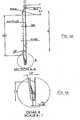
- FIG. 2is a schematic, exploded view of sensor assembly 25, including an envelope 5 having an envelope cover 10 and an envelope base 20; a force-sensitive resistor (FSR) sensor 30; an electrical connection unit 40; and an absorbent protective layer 50 for disposing on FSR sensor 30.
- FSRforce-sensitive resistor
- Figure 3Ais a cross-sectional view of envelope cover 10
- Figure 3Bis a magnified view of a portion of envelope cover 10 shown in Figure 3A
- Figure 3Cis a cross-sectional view of sensor assembly 25 showing the relative disposition of envelope cover 10, envelope base 20, FSR sensor 30, and absorbent layer 50.
- the rims of cover 10 and base 20are preferably contoured in complementary fashion.
- the closure of these rimsis preferably made by ultrasonic welding.
- the bonding of the rims, coupled with the curved structure near the perimeter and the elevated rim thereunder,provide the requisite rigidity to the envelope. Consequently, routine forces exerted by the foot on the sensor will not collapse cover 10 near the envelope perimeter, and the collapsing is confined within the center area of the cover.
- the bonding of the rimsactually generates a surface tension that allows the cover to collapse solely within that center area. This also eliminates distortion of the rims.
- the above-described features of the envelope and closure thereofallow more accurate, repeatable and reproducible collapse of cover 10 upon sensor 30 . This permits repeatable readings of the sensor for a specific pressure (force). Perhaps more importantly, the above-described shape and structure eliminate or drastically reduce shear forces on sensor 30 , and greatly contribute to the longevity of FSR sensor 30 . The structure of the rims also improves the structural stability and durability of the envelope.
- the sensoris anchored to the base of the envelope within a specific socket structure in base 20 .
- the wiresare tightened by a metal crimp, which is positionally locked into the socket, thereby inhibiting movement of the sensor, as well as undesirable tension in the area of the wires (and especially to the welding points thereof) of electrical connection unit 40 as result of accidental pulling of the external wire.
- the senoris attached to the shoe inner surface by loop and hook fasteners such as Velcro ® .
- One fastening elementis attached to the bottom of sensor base cover, and the complementary fastening element is attached to the shoe insole.
- a graphical symbol of a footis preferably provided on cover 10 , so as to direct the user to properly align the FSR sensor device within the shoe.
- the envelopeis easy and inexpensive to manufacture, and enables facile and reproducible assembly of the FSR sensor device.
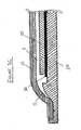
- Figure 3Dschematically illustrates a mechanism for advantageously securing FSR sensor 30 to external wires 58 .
- Wires 58typically connect FSR sensor 30 with the head of the sensor device containing, inter alia, the microprocessor and radio frequency (RF) transceiver.
- RFradio frequency
- External wires 58are anchored around protrusions such as protrusion 56 , which juts out of a base 54 of FSR sensor 30 . External wires 58 are wrapped around these protrusions in such a way that undesirable tension in the area of the wires (especially at the welding points 59 ) of the electrical connection is avoided.
- This anchoring mechanismenables the user to pull the envelope out of the shoe without inadvertently causing damage to the welding points in the area of the electrical connection.
- siliconis poured over the ends of wires 58 after wires 58 have been positioned, so as to maintain the positioning of the wires during assembly, as well as to further protect the welding area and to seal out water and dirt from the opening around the wire.
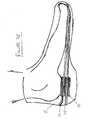
- Figure 3Eis a schematic illustration of the sensor assembly 25 disposed within a conventional shoe or footwear 15.
- Sensor assembly 25can be situated in various positions, e.g., under the foot/above the insole, between the insole and sole, and within the sole.
- footwearrefers to any kind of foot covering that a foot being covered presses down upon during gait, including, but not limited to, shoes, boots, sandals, socks, and stockings.
- Figure 4is a schematic electronic diagram of a foot sensor device 100.
- Sensor element 16is connected to, and preferably powered by, electronics or communication unit 31 by means of wiring 21.
- Communication unit 31includes a digital circuit and microcontroller unit 80, a radio frequency (RF) transceiver 82, and an antenna unit 83 having a matching network for converting the signal from the wired medium to a wireless medium, and from the wireless medium to the wired medium.
- RFradio frequency
- Foot sensor device 100may be equipped with a voltage divider consisting of sensor element 16 and a bias resistor 81 (preferably disposed in unit 30 ), in order to measure the resistance of sensor element 16 .
- a voltageis applied to the voltage divider, the voltage is divided according to the resistance ratio between sensor element 16 and bias resistor 81 . This voltage is measured in order to assess the resistance of sensor element 16.
- Communication unit 31is also equipped with a small coin battery 84 that provides power to microcontroller unit 80 , RF transceiver 82 , and sensor element 16 .
- Digital circuit and microcontroller unit 80controls and monitors the operation of foot sensor device 100 and executes the various algorithms (e.g., gait detection, RF control, and power management algorithms) thereof.
- microcontroller unit 80communicates with RF transceiver 82 via a Serial Peripheral Interface (SPI).
- SPISerial Peripheral Interface
- FIG. 5is a schematic electronic diagram of an example of the functional electrical stimulation (FES) system 500, showing the internal workings of foot sensor device 100, stimulator unit 150, and control unit 250, and the communication therebetween.
- FESfunctional electrical stimulation
- foot sensor device 100includes small coin battery 84 that provides power to microcontroller unit 80, RF transceiver 82, and sensor element 16 .
- Coin battery 84may also power an analog circuit 78 having sensor signal conditioning (such as amplification, filtering, and division) and an analog-to-digital signal converter.
- Stimulator unit 150typically includes an RF transceiver 182 having an antenna 183 having a matching network, a digital circuit and microcontroller unit 180, and a stimulation circuit 195, all powered by a power supply 184b.
- Stimulation circuit 195typically receives power from power supply 184b via high voltage circuit 190.
- Power supply 184bmay be powered by a battery such as rechargeable battery 184a.
- a charging and battery monitor 184cis advantageously associated with rechargeable battery 184a, and interfaces with an external power supply, such as a regulated, preferably medical-grade, wall adapter.
- RF transceiver 82communicates with RF transceiver 182 of stimulator unit 150.
- RF transceiver 182transmits digital information to and receives digital information from digital circuit and microcontroller unit 180.
- microcontroller unit 180 and stimulation circuit 195exchange digital information.
- Stimulation circuit 195based on digital information from microcontroller unit 180, and powered by high voltage circuit 190, is configured to deliver electrical stimulation pulses to the patient by means of electrodes 196a, 196b disposed in the orthosis unit.
- Control unit 250typically includes an RF transceiver 282 having an antenna 283 having a matching network, a digital circuit and microcontroller unit 280, and a user interface circuit 192, all powered by a power supply 284b.
- Power supply 284bmay be powered by a battery such as rechargeable battery 284a.
- a charging and battery monitor 284cis advantageously associated with rechargeable battery 284a, and interfaces with an external power supply, such as a regulated, preferably medical-grade, wall adapter.
- RF transceiver 182communicates with RF transceiver 282 of control unit 250.
- RF transceiver 282transmits digital information to and receives digital information from digital circuit and microcontroller unit 280.
- microcontroller unit 280 and user interface circuit 192exchange digital information.
- user preferences for various operating parameterscan be communicated from user interface circuit 192 to microcontroller unit 280.
- Microcontroller unit 280may be adapted to provide user interface circuit 192 with display information, including pertaining to stimulation parameters.
- PDAssuch as PDA 450 are small, hand-held portable computers having a Central Processing Unit (CPU) and electronic memory, and are generally used for storing and organizing information and for providing tools for everyday tasks.
- the PDAmay advantageously be operated by the Windows Mobile 5 software of Microsoft®.
- PDA 450preferably has a database containing a gait log and various personal parameters of the patient, and is programmed to configure the stimulation parameters of the electrical stimulation system.
- PDA 450 and control unit 250are preferably in digital and electrical communication, such that the orthosis system can be configured on-line by the clinician during actual usage of the orthosis by the patient.
- control unit 250actually serves as the transmitter of PDA 450, enabling PDA 450, via control unit 250, to communicate with and command the other components of the electrical stimulation system.
- a microprocessor within the systemby means of the RF protocol software, implements a method for a Fast wireless Link Failure Identification (FLFI). If failure is identified, the system provides a fail-safe stimulation to promote gait stability.
- FLFIFast wireless Link Failure Identification
- the term "stance time”refers to the time differential between a heel-off event and the previous heel-contact event.
- wing timerefers to the time differential between a heel-contact event and the previous heel-off event.
- the systeme.g., microcontroller unit 80 of foot sensor device 100 or in other possible embodiments, microcontroller unit 180 of stimulator unit 150 ) frequently or substantially constantly calculates, and/or monitors, the last or average stance time of the patient. From the average stance time, microcontroller unit 80 calculates a 'keep-alive' duration, which is longer than the stance time.
- the 'keep-alive' durationis at least one hundredth of a second, more preferably, at least one tenth of a second, most preferably, at least 0.8 seconds.
- the 'keep-alive' durationis at least 0.01 times the stance time, preferably, at least 0.1 times the stance time, and most preferably, at least slightly longer than the stance time.
- Microcontroller unit 80transmits this 'keep-alive' duration along with any heel event, to stimulator unit 150.
- microcontroller unit 180recognizes that the link with foot sensor device 100 is not functional (no event message, nor 'keep-alive' message), and in the absence of gait event information, commands stimulation circuit 195 to apply a fail-safe stimulation for a pre-defined period of time.
- the fail-safe stimulationis delivered to the tissue slightly after the heel-off event should have been received, had no RF blocking occurred, since the 'keep-alive' duration is calculated based on the stance duration. This fail-safe stimulation helps the patient with dorsiflexion and reduces the risk of falling by substantially imitating the function of a mechanical orthosis (ankle-foot orthosis).
- FES system 500employs a registration mechanism that enables several such systems to simultaneously operate in the same frequency channel.
- the registrationis based on a unique identifier, preferably incorporated into the hardware of control unit 250, which serves as a digital 'family name' for all of the components of FES system 500 : foot sensor device 100 , stimulator unit 150, and control unit 250.
- Each transmission of each system component 100, 150, 250preferably carries this identifier as a part of the payload.
- the transceiverfirst verifies that the transmitter belongs (is registered) to the same family, and only after verification proceeds to handle the transmitted data.
- the registration processalso defines how the new component is introduced into an existing system, for example, as a replacement part.
- the end usermoves the system to 'registration mode' by pressing a pre-defined key sequence on control unit 250.
- this key sequenceis the same, regardless of the new component that is being introduced (registered) to FES system 500.
- a microcontroller unit such as microcontroller unit 80 of foot sensor device 100(or another microcontroller unit within the system, such as microcontroller unit 180 of stimulator unit 150) is preferably configured to implement a 'Dynamic Gait Tracking' algorithm. This algorithm is designed to handle variable sensor response arising from various sources, including:
- Figure 6is an exemplary block diagram showing the logical sequence of analysis and control performed by microcontroller unit 80 of foot sensor device 100 , based on data received from pressure transducer 16 .
- step 7the signal sampled in step 1 is compared with high threshold 404 and low threshold 406 (step 7), and microcontroller unit 80 determines (using signal data from at least one previous sampling) whether high threshold 404 or low threshold 406 has been crossed (step 8). If either threshold has been crossed, microcontroller unit 80 effects a change in the state of the system (step 9), from a STANCE state to a SWING state, triggering electrical stimulation, or from a SWING state to a STANCE state, triggering a cutting off of the stimulation.
- step 9The logical sequence of analysis and control returns to step 1, in which microcontroller unit 80 again samples the signal of pressure transducer 16 .
- microcontroller unit 80determines, in step 8, that high threshold 404 or low threshold 406 has not been crossed, the time elapsed within the current system state (STANCE or SWING) is evaluated (step 10). If the time elapsed exceeds a particular value, e.g., a calculated value based on the average stance/swing period, microcontroller unit 80 determines (step 11) that the user of the FES system is now in a STANDING state or in a SITTING state.
- STANCE or SWINGthe time elapsed within the current system state
- each of points 407represents a crossing of high threshold 404; each of points 409 represents a crossing of low threshold 406.
- microcontroller unit 80After determining that high threshold 404 has been crossed, microcontroller unit 80 effects a change in the state of the system from a SWING state 416 to a STANCE state 418. Similarly, upon determining that low threshold 406 has been crossed, microcontroller unit 80 effects a change in the state of the system from a STANCE state to a SWING state.
- stimulation circuit 195is commanded to provide stimulation current during the course of SWING state 416 .
- microcontroller unit 80determines that the state of the user has changed from a SWING state to a SITTING state.
- microcontroller unit 80determines whether a peak or valley is valid or invalid.
- Peak 414is an example of a valid peak
- valley 416is an example of a valid valley.
- An invalid peaksuch as invalid peak 420
- a peakmay be considered invalid if the peak amplitude is less than a pre-determined percentage of the dynamic range.
- a valleymay be an invalid valley such as invalid valley 420 , if the amplitude of the valley (i.e., the drop in pressure from the previous peak to the valley is less than a pre-determined percentage of the dynamic range.
- Figure 8is a schematic, simplified plot showing the pressure exerted on the pressure transducer as a function of time, during gait assisted by a system of the present invention.
- the time elapsed for valley 442greatly exceeds the time elapsed for typical valleys such as valleys 444 .
- microcontroller unit 80determines that the state of the user has changed from a SWING state to a SITTING state.
- microcontroller unit 80determines that the state of the user has changed from STANCE to STANDING.
- Each gait statepreferably has an individual, dynamic threshold -- typically a percentage or other function of the dynamic range -- for determining peak and valley validity. This threshold should not to be confused with the heel-off and heel-contact thresholds described hereinabove.
- a relatively high thresholdreduces the occurrence of false stimulation.
- the systemis largely impervious to the effects of weight shifting while sitting, because the relatively low peaks generated by such weight shifting are considered invalid, and are not 'entered' into the trendline calculation. Consequently, these false gait peaks do not "pull" downward the peak trendline, do not decrease the dynamic range, and do not falsely sensitize the stimulation threshold (low threshold).
- the userenjoys a more quiet sitting, in which false stimulation while sitting is appreciably reduced.
- STANCE statevalid peak amplitude ⁇ 25% ⁇ dynamic range
- STANDING statevalid peak amplitude ⁇ 62.5% ⁇ dynamic range
- SWING statevalid valley amplitude ⁇ 25% ⁇ dynamic range
- SITTING statevalid valley amplitude ⁇ 50% ⁇ dynamic range
- Peak 446 and peak 448are of substantially equal amplitude, peak 446 is considered to be a valid peak, while peak 448 is considered to be an invalid peak. Peak 446 belongs to the SWING state, whereas peak 448 belongs to the SITTING state.
- the softwarepreferably samples the signals before and during each of the stimulation pulses.
- the monitored parameters and conditionsmay include:
- FIG 9is a schematic plot of current as a function of time, for a bipolar stimulation pulse 450 of the prior art.
- Stimulation pulse 450is substantially a square wave having a positive current phase 452 and a negative current phase 454 .
- the voltage applied to the human bodygenerally cannot be raised above a certain level, e.g., 120 Volts, consequently, as the impedance builds up, the current delivered may be limited - even severely limited - by the ceiling voltage.
- stimulator devices of the prior artare often constant voltage devices.
- positive current phase 452is substantially a square wave.
- point Bthe impedance of the tissue has increased, but the source voltage still exceeds the multiplication product I ⁇ Z.
- the impedance of the tissuehas increased to the point that the source voltage exactly equals the multiplication product I ⁇ Z.
- point Ea further build-up in the impedance of the tissue forces the current delivered to drop (point D ), monotonically, until positive current phase 452 is completed (point E ).
- Positive current phase 452is not, therefore, a perfect square wave, and the total charge delivered is substantially less than the calculated total current based on the square wave model. Consequently, the total charge delivered in negative current phase 454 tends to exceed the total charge delivered in positive current phase 452, which often results in skin irritation in the area through which the current is passed.
- Such stimulator devices of the prior artare of further disadvantage in that the use of constant voltage near the beginning of positive current phase 452 can be wasteful from an energy standpoint.
- FIG. 11is a block diagram showing an exemplary logical sequence of sampling, analysis and control performed by a microcontroller unit of the present disclosure. The sequence is designed to adjust or balance a bipolar digital stimulation current pulse 550 delivered by stimulation circuit 195 .
- a positive current phase 552a of bipolar current pulse 550is sampled/monitored over n preferably evenly-spaced sample points.
- the voltageis also sampled/monitored, and the impedance is calculated.
- the sampling/monitoringis preferably conducted at least 3 times, and more preferably, at least 5 times, over the duration of positive current phase 552a. In terms of timing, sampling is preferably conducted at least once every 10 microseconds over the duration of positive current phase 552a.
- a negative current phase 554a of bipolar current pulse 550is sampled/monitored over m preferably evenly-spaced sample points.
- the voltageis also sampled/monitored.
- pulse balancingis performed (step 6), preferably on at least one of positive current phase 552b and negative current phase 554b of the next current pulse.
- the pulse balancingis performed by controlling at least one pulse parameter so as to improve charge balance between positive current phase 552a and a negative current phase such as negative current phase 554b .
- Various pulse parametersmay be controlled to improve the charge balancing, including at least one of the following: current (positive phase or negative phase), positive current phase width, and negative current phase width.
- charge balancingis performed by controlling a pulse parameter of the negative phase.
- Figure 12reduced phase amplitude of a negative current phase
- Figure 13reduced phase width (duration) of a negative current phase
- Figure 14increased current to a greater than nominal level, at least during a portion of the positive current phase.
- the voltageis adjusted to achieve substantially the minimum voltage satisfying Ohm's Law, so as to conserve energy/battery power.
Landscapes
- Health & Medical Sciences (AREA)
- Life Sciences & Earth Sciences (AREA)
- Veterinary Medicine (AREA)
- Public Health (AREA)
- General Health & Medical Sciences (AREA)
- Animal Behavior & Ethology (AREA)
- Biomedical Technology (AREA)
- Engineering & Computer Science (AREA)
- Radiology & Medical Imaging (AREA)
- Nuclear Medicine, Radiotherapy & Molecular Imaging (AREA)
- Biophysics (AREA)
- Heart & Thoracic Surgery (AREA)
- Physics & Mathematics (AREA)
- Physical Education & Sports Medicine (AREA)
- Oral & Maxillofacial Surgery (AREA)
- Dentistry (AREA)
- Pathology (AREA)
- Medical Informatics (AREA)
- Molecular Biology (AREA)
- Surgery (AREA)
- General Physics & Mathematics (AREA)
- Physiology (AREA)
- Epidemiology (AREA)
- Pain & Pain Management (AREA)
- Rehabilitation Therapy (AREA)
- Measurement Of The Respiration, Hearing Ability, Form, And Blood Characteristics Of Living Organisms (AREA)
- Electrotherapy Devices (AREA)
Description
- The present disclosure relates to functional electrical stimulation (FES) devices and systems and, more particularly, to an improved envelope for force-sensitive resistors of such devices, and to FES devices and systems having improved monitoring, analysis, control, safety, energy conservation, and communication features.
- It is known that various pathologies of the neuromuscular system due to disease or trauma to the central nervous system, such as stroke, spinal cord injury, head injury, cerebral palsy and multiple sclerosis, can impede proper limb functioning of the legs. Gait, the biomechanical description of walking, can suffer static and dynamic parameter variations due to neuromuscular impairments that cause non-symmetrical walking and reduced walking speed and stability, and often require increased energy consumption.
- Drop foot describes the gait attributable to weak or uncoordinated activation of the ankle dorsi-flexors due to disease or trauma to the central nervous system. A patient suffering from drop foot tends to drag the foot during the swing phase of walking and usually try to compensate for this dragging by hiking the hip or swinging the affected leg in a circular motion. These patients tend to have impaired stability, are prone to frequent falls, and have walking movements that are unaesthetic and energy consuming.
- It is known, however, that functional electrical stimulation (FES) can generally be used to activate the leg muscles of such patients. Precisely timed bursts of short electrical pulses are applied to motor nerves to generate muscle contractions, which are synchronized with the gait of the patient, so as to improve the leg function and enhance the gait. The timing of these pulses is critical, and must be synchronized with the gait. This is advantageously achieved by sensing gait events such as a foot-floor force reaction, using a force-sensitive resistor (FSR) disposed beneath the heel region of the patient, and transmitting the information to the stimulator unit.
- The FSR sensor must be protected against water, humidity, dirt, and mechanical stress by means of a casing or envelope.
U.S. Patent 6,507,757 to Swain, et al. , discloses one typical foot sensor device of the prior art, in which a foot pressure switch, or sensor, is permanently disposed in the shoe of the affected leg. An electrical circuit is interrupted during the stance phase, when a significant weight is placed on the heel, and reconnects when the heel is lifted during the swing phase. Wires disposed under the clothing connect the sensor with an external stimulator unit that can be attached to the belt or kept in a pocket of the user. The stimulator unit is connected to the electrodes by additional electrical wires.- The cumbersome wires may be obviated by using a radio frequency (RF) system in which the foot sensor device and other components of the FES orthotic system communicate in a wireless fashion. However, the use of such an RF system necessitates integrating an RF transmitting unit, or head, within the foot sensor device. The RF communication with other components of the FES orthotic system must be robust and reliable, even in areas in which various types of wireless signals are prevalent, such as local area networks (LANs). The FES orthotic system must also be robust and reliable in areas in FES clinics and the like, in which one or more additional wireless FES systems may be operating simultaneously.
- There is therefore a recognized need for, and it would be highly advantageous to have, an FES orthotic system for neuroprosthetic gait enhancement that overcomes the various deficiencies of the known systems. It would be of particular advantage for such a system that is robust and reliable, avoids the discomfort associated with various prior art stimulation devices, and is secured so as to operate in a safe and robust fashion.
- Relevant prior art is disclosed by
US 2004/122483 A1 andUS 2006/020421 A1 . - According to the present invention, which is defined by
claim 1, there is provided a gait modulation system utilizing functional electrical stimulation for improving lower-limb function of a patient having neuromuscular impairment of a lower limb, the gait modulation system comprising: (a) at least one sensor adapted for associating with at least one lower limb of the patient, said sensor for transducing at least one parameter related to a gait of the patient, so as to obtain gait data related to said gait; (b) a muscle stimulator including: (i) an electrical stimulation circuit, said circuit adapted to supply an electrical stimulation output to an electrode array for performing functional electrical stimulation of at least one muscle of the lower limb, and (c) a microprocessor, operatively connected to said at least one sensor, said microprocessor adapted for: receiving a signal containing gait information based on said gait data; processing said signal, and controlling said stimulation output based on said processing of said signal, wherein said processing said signal includes: (i) calculating a dynamic range between maximal parameter values, and minimal parameter values on said sensor, and (ii) calculating a high threshold and a low threshold based on said dynamic range, said low threshold for triggering on said electrical stimulation output, said high threshold for triggering off said electrical stimulation output. - Preferably, the sensor is a pressure sensor, wherein said processing the signal includes: (i) calculating a dynamic range between maximal pressure values, and minimal pressure values on the pressure sensor, and (ii) calculating a high threshold and a low threshold based on the dynamic range, the low threshold for triggering on the electrical stimulation output, the high threshold for triggering off the electrical stimulation output.
- According to still further features in the described preferred embodiments, the microprocessor is further adapted to detect a deviation from an ambulating mode.
- According to still further features in the described preferred embodiments, the ambulating mode is a SWING state.
- According to still further features in the described preferred embodiments, the ambulating mode is a STANCE state.
- According to still further features in the described preferred embodiments, the microprocessor is further adapted to identify invalid peaks or valleys.
- According to still further features in the described preferred embodiments, the microprocessor is further adapted to determine whether the patient is in a SWING, STANCE, SITTING, or STANDING state.
- According to still further features in the described preferred embodiments, the microprocessor is further adapted to make a determination of an ambulating state of the patient, and to identify invalid peaks or valleys based on the determination.
- According to still further features in the described preferred embodiments, the microprocessor is further adapted to utilize the dynamic range in identifying the invalid peaks or valleys.
- According to still further features in the described preferred embodiments, the microprocessor has a plurality of different thresholds for determining peak validity or valley validity, the plurality of different thresholds based, at least in part, on an ambulating state of the patient.
- The invention is herein described, by way of example only, with reference to the accompanying drawings. With specific reference now to the drawings in detail, it is stressed that the particulars shown are by way of example and for purposes of illustrative discussion of the preferred embodiments of the present invention only, and are presented in the cause of providing what is believed to be the most useful and readily understood description of the principles and conceptual aspects of the invention. In this regard, no attempt is made to show structural details of the invention in more detail than is necessary for a fundamental understanding of the invention, the description taken with the drawings making apparent to those skilled in the art how the several forms of the invention may be embodied in practice. Throughout the drawings, like-referenced characters are used to designate like elements.
- In the drawings:
Figure 1 is a perspective view of a sensor assembly;Figure 2 is a schematic, exploded view of the sensor assembly, including an envelope cover, an envelope base, an FSR sensor, an electrical connection unit, and an absorbent protective layer for disposing on the FSR sensor;Figure 3A is a cross-sectional view of the envelope cover;Figure 3B is a magnified view of a portion ofFigure 3A ;Figure 3C is a cross-sectional view of the envelope showing the relative disposition of the envelope cover, envelope base, FSR sensor, and absorbent layer;Figure 3D is a schematic illustration of an example of the envelope in which the envelope has a mechanism for advantageously securing FSR sensor to external wires;Figure 3E is a schematic illustration of the sensor assembly disposed within a conventional shoe;Figure 4 is a schematic electronic diagram of the foot sensor device;Figure 5 is a schematic electronic diagram of a functional electrical stimulation (FES) system, showing the internal workings of the foot sensor device, stimulator unit, and control unit, along with the communication between the components;Figure 6 is a schematic plot showing the pressure exerted on a pressure transducer as a function of time, during gait assisted by the system of the present invention;Figure 7 is an exemplary block diagram showing the logical sequence of analysis and control performed by a microcontroller unit of the present invention, based on data received from the pressure transducer;Figure 8 is a schematic, simplified plot showing the pressure exerted on the pressure sensor as a function of time, during gait assisted by a system of the present invention;Figure 9 is a schematic plot of current as a function of time for a bipolar stimulation pulse of the prior art;Figure 10 is a schematic plot of current as a function of time for successive bipolar stimulation pulses, showing exemplary sampling points;Figure 11 is a block diagram showing an exemple of a logical sequence of sampling, analysis and control performed by a microcontroller unit of the present disclosure;Figure 12 is a schematic plot showing one example of charge balancingreduced phase amplitude of a negative current phase;Figure 13 is a schematic plot showing another example of charge balancing -- reduced phase width (duration) of a negative current phase, andFigure 14 is a schematic plot showing yet another example of charge balancing -- increased current to a greater than nominal level during a low-impedance section of the positive current phase.- The principles and operation of the present invention may be better understood with reference to the drawings and the accompanying description.
- Before explaining at least one embodiment of the invention in detail, it is to be understood that the invention is not limited in its application to the details of construction and the arrangement of the components set forth in the following description or illustrated in the drawings. The invention is capable of other embodiments or of being practiced or carried out in various ways. Also, it is to be understood that the phraseology and terminology employed herein is for the purpose of description and should not be regarded as limiting.
- Various prior art sensor envelopes have appreciable deficiencies. One particular disadvantage is the lack of sufficient protection of the sensor by the sensor envelope. This lack of protection may cause an uncontrolled or uneven force distribution over the surface of the sensor, resulting in a relatively short life span for the sensor.
- The FSR sensor assembly and envelope of the present disclosure is designed, preferably, for inserting under the inner sole (insole) of the shoe, typically beneath the heel. The protective casing is made of a cover and a base, with the sensor fitting therebetween. An additional piece of absorbent material is disposed between the cover and the FSR sensor. Typically, the absorbent material is adhered to the cover. The cover and base of the sensor casing can be connected to each other by ultrasonic welding, gluing, heat welding, RF welding or by pins. Various commercially-available force-sensitive resistor (FSR) sensors are suitable for use in conjunction with the casing, including some FSRs manufactured by Interlink®, CUI®, Tekscan®, and Peratech®. The casing can also be used with other types of sensors such as membrane switches, capacitance-based sensors and piezo-electric foils.
- The envelope is preferably made of acetal [also known as polyacetal, polyoxymethylene (POM), or polyformaldehyde] or polypropylene, but other materials may be engineered to provide the requisite physical and mechanical properties, e.g., polyethylene terephthalate (PET).
Figure 1 is a perspective view of asensor assembly 25.Figure 2 is a schematic, exploded view ofsensor assembly 25, including anenvelope 5 having anenvelope cover 10 and anenvelope base 20; a force-sensitive resistor (FSR)sensor 30; anelectrical connection unit 40; and an absorbentprotective layer 50 for disposing onFSR sensor 30.Base 20 forms sockets forFSR sensor 30 and forelectrical connection unit 40. The sockets are preferably contoured to match the topographical features of the underside of the sensor and electrical connection unit.Base 20 has a circumferential rim for closely boundingFSR sensor 30, thereby determining the position of the sensor. Thus, the sockets enable precise, repeatable location of the sensor on the base.- Preferably,
envelope base 20 is harder/less flexible thancover 10. This mechanical property reinforces the FSR sensor against bending forces, which can cause deviations in the sensor readings and can also cause excessive wear and damage to the sensor. Figure 3A is a cross-sectional view ofenvelope cover 10;Figure 3B is a magnified view of a portion of envelope cover10 shown inFigure 3A ;Figure 3C is a cross-sectional view ofsensor assembly 25 showing the relative disposition ofenvelope cover 10,envelope base 20,FSR sensor 30, andabsorbent layer 50.- It is evident from
Figures 3A-3C that envelope cover10 is supported around the circumference and largely unsupported towards the center. It is further evident fromFigure 3C thatenvelope cover 10,envelope base 20, andabsorbent layer 50 are disposed such that a firstvoid space 11 is situated betweenenvelope cover 10 andabsorbent layer 50, and such that a secondvoid space 13 is situated betweenenvelope cover 10 andenvelope base 20. The flexibility ofcover 10, along with the maneuverability provided byvoid spaces FSR sensor 30, and transmits the pressure (force), via absorbentprotective layer 50, thereto. - Preferably, the radius of
cover 10 near the perimeter thereof is about 2-5mm and more preferably, 3-4mm. - The rims of
cover 10 andbase 20 are preferably contoured in complementary fashion. The closure of these rims is preferably made by ultrasonic welding. The bonding of the rims, coupled with the curved structure near the perimeter and the elevated rim thereunder, provide the requisite rigidity to the envelope. Consequently, routine forces exerted by the foot on the sensor will not collapsecover 10 near the envelope perimeter, and the collapsing is confined within the center area of the cover. The bonding of the rims actually generates a surface tension that allows the cover to collapse solely within that center area. This also eliminates distortion of the rims. - Absorbent
protective layer 50, for disposing onFSR sensor 30, is preferably made of Poron®, or another flexible, high density, microcellular material that exhibits, over long-term use, good resistance to compression set (collapse), high resiliency, and good impact absorption. - The above-described features of the envelope and closure thereof allow more accurate, repeatable and reproducible collapse of
cover 10 uponsensor 30. This permits repeatable readings of the sensor for a specific pressure (force). Perhaps more importantly, the above-described shape and structure eliminate or drastically reduce shear forces onsensor 30, and greatly contribute to the longevity ofFSR sensor 30. The structure of the rims also improves the structural stability and durability of the envelope. - The sensor is anchored to the base of the envelope within a specific socket structure in
base 20. In one example, the wires are tightened by a metal crimp, which is positionally locked into the socket, thereby inhibiting movement of the sensor, as well as undesirable tension in the area of the wires (and especially to the welding points thereof) ofelectrical connection unit 40 as result of accidental pulling of the external wire. - Preferably, the sensor is attached to the shoe inner surface by loop and hook fasteners such as Velcro®. One fastening element is attached to the bottom of sensor base cover, and the complementary fastening element is attached to the shoe insole.
- A graphical symbol of a foot is preferably provided on
cover 10, so as to direct the user to properly align the FSR sensor device within the shoe. - The envelope is easy and inexpensive to manufacture, and enables facile and reproducible assembly of the FSR sensor device.
Figure 3D schematically illustrates a mechanism for advantageously securingFSR sensor 30 toexternal wires 58.Wires 58 typically connectFSR sensor 30 with the head of the sensor device containing, inter alia, the microprocessor and radio frequency (RF) transceiver.External wires 58 are anchored around protrusions such asprotrusion 56, which juts out of abase 54 ofFSR sensor 30.External wires 58 are wrapped around these protrusions in such a way that undesirable tension in the area of the wires (especially at the welding points59) of the electrical connection is avoided. This anchoring mechanism enables the user to pull the envelope out of the shoe without inadvertently causing damage to the welding points in the area of the electrical connection.- Preferably, silicon is poured over the ends of
wires 58 afterwires 58 have been positioned, so as to maintain the positioning of the wires during assembly, as well as to further protect the welding area and to seal out water and dirt from the opening around the wire. Figure 3E is a schematic illustration of thesensor assembly 25 disposed within a conventional shoe orfootwear 15.Sensor assembly 25 can be situated in various positions, e.g., under the foot/above the insole, between the insole and sole, and within the sole.- As used herein, the term "footwear" refers to any kind of foot covering that a foot being covered presses down upon during gait, including, but not limited to, shoes, boots, sandals, socks, and stockings.
Figure 4 is a schematic electronic diagram of afoot sensor device 100.Sensor element 16 is connected to, and preferably powered by, electronics orcommunication unit 31 by means ofwiring 21.Communication unit 31 includes a digital circuit andmicrocontroller unit 80, a radio frequency (RF)transceiver 82, and anantenna unit 83 having a matching network for converting the signal from the wired medium to a wireless medium, and from the wireless medium to the wired medium.- The resistance of
sensor element 16 changes with the force applied thereon.Foot sensor device 100 may be equipped with a voltage divider consisting ofsensor element 16 and a bias resistor81 (preferably disposed in unit30), in order to measure the resistance ofsensor element 16. When a voltage is applied to the voltage divider, the voltage is divided according to the resistance ratio betweensensor element 16 andbias resistor 81. This voltage is measured in order to assess the resistance ofsensor element 16. - One skilled in the art will appreciate that there are numerous ways of measuring the resistance of
sensor element 16. Communication unit 31 is also equipped with asmall coin battery 84 that provides power tomicrocontroller unit 80,RF transceiver 82, andsensor element 16.- Digital circuit and
microcontroller unit 80 controls and monitors the operation offoot sensor device 100 and executes the various algorithms (e.g., gait detection, RF control, and power management algorithms) thereof. Preferably,microcontroller unit 80 communicates withRF transceiver 82 via a Serial Peripheral Interface (SPI). Figure 5 is a schematic electronic diagram of an example of the functional electrical stimulation (FES)system 500, showing the internal workings offoot sensor device 100,stimulator unit 150, andcontrol unit 250, and the communication therebetween.- As above,
foot sensor device 100 includessmall coin battery 84 that provides power tomicrocontroller unit 80,RF transceiver 82, andsensor element 16.Coin battery 84 may also power ananalog circuit 78 having sensor signal conditioning (such as amplification, filtering, and division) and an analog-to-digital signal converter. Stimulator unit 150 typically includes anRF transceiver 182 having anantenna 183 having a matching network, a digital circuit andmicrocontroller unit 180, and astimulation circuit 195, all powered by a power supply184b.Stimulation circuit 195 typically receives power from power supply184b viahigh voltage circuit 190.- Power supply184b may be powered by a battery such as
rechargeable battery 184a. A charging and battery monitor184c is advantageously associated withrechargeable battery 184a, and interfaces with an external power supply, such as a regulated, preferably medical-grade, wall adapter. - By means of
antenna 83 offoot sensor device 100 andantenna 183 ofstimulator unit 150,RF transceiver 82 communicates withRF transceiver 182 ofstimulator unit 150.RF transceiver 182 transmits digital information to and receives digital information from digital circuit andmicrocontroller unit 180. Similarly,microcontroller unit 180 andstimulation circuit 195 exchange digital information.Stimulation circuit 195, based on digital information frommicrocontroller unit 180, and powered byhigh voltage circuit 190, is configured to deliver electrical stimulation pulses to the patient by means of electrodes196a, 196b disposed in the orthosis unit. Control unit 250 typically includes anRF transceiver 282 having anantenna 283 having a matching network, a digital circuit andmicrocontroller unit 280, and a user interface circuit192, all powered by apower supply 284b.Power supply 284b may be powered by a battery such as rechargeable battery284a. A charging and battery monitor284c is advantageously associated with rechargeable battery284a, and interfaces with an external power supply, such as a regulated, preferably medical-grade, wall adapter.- By means of
antenna 183 ofstimulator unit 150 andantenna 283 ofcontrol unit 250,RF transceiver 182 communicates withRF transceiver 282 ofcontrol unit 250.RF transceiver 282 transmits digital information to and receives digital information from digital circuit andmicrocontroller unit 280. Similarly,microcontroller unit 280 and user interface circuit192 exchange digital information. For example, user preferences for various operating parameters can be communicated from user interface circuit192 tomicrocontroller unit 280.Microcontroller unit 280 may be adapted to provide user interface circuit192 with display information, including pertaining to stimulation parameters. - As is known in the art, PDAs such as
PDA 450 are small, hand-held portable computers having a Central Processing Unit (CPU) and electronic memory, and are generally used for storing and organizing information and for providing tools for everyday tasks. The PDA may advantageously be operated by theWindows Mobile 5 software of Microsoft®.PDA 450 preferably has a database containing a gait log and various personal parameters of the patient, and is programmed to configure the stimulation parameters of the electrical stimulation system. PDA 450 andcontrol unit 250 are preferably in digital and electrical communication, such that the orthosis system can be configured on-line by the clinician during actual usage of the orthosis by the patient. In this arrangement,control unit 250 actually serves as the transmitter ofPDA 450, enablingPDA 450, viacontrol unit 250, to communicate with and command the other components of the electrical stimulation system.- A microprocessor within the system, by means of the RF protocol software, implements a method for a Fast wireless Link Failure Identification (FLFI). If failure is identified, the system provides a fail-safe stimulation to promote gait stability.
- As used herein in the specification and in the claims section that follows, the term "stance time" refers to the time differential between a heel-off event and the previous heel-contact event.
- As used herein in the specification and in the claims section that follows, the term "swing time" refers to the time differential between a heel-contact event and the previous heel-off event.
- When, for whatever reason, a 'heel-off' event is not identified immediately after receiving or identifying a 'heel-contact' event, the situation of the user may be precarious: the stimulator resumes its 'heel-contact' activity and does not deliver stimulation, which may cause the patient to lose balance, to stumble, or even to fall.
- In order to reduce this risk, the system (e.g.,
microcontroller unit 80 offoot sensor device 100 or in other possible embodiments,microcontroller unit 180 of stimulator unit150) frequently or substantially constantly calculates, and/or monitors, the last or average stance time of the patient. From the average stance time,microcontroller unit 80 calculates a 'keep-alive' duration, which is longer than the stance time. Preferably, the 'keep-alive' duration is at least one hundredth of a second, more preferably, at least one tenth of a second, most preferably, at least 0.8 seconds. As a function of stance time, preferably, the 'keep-alive' duration is at least 0.01 times the stance time, preferably, at least 0.1 times the stance time, and most preferably, at least slightly longer than the stance time. Microcontroller unit 80 transmits this 'keep-alive' duration along with any heel event, tostimulator unit 150.- If, after detecting a heel-contact event,
microcontroller unit 80 does not detect a heel-off condition,microcontroller unit 80 transmits a 'keep-alive' message after the 'keep-alive' duration, so thatstimulator unit 150 is aware that the link withfoot sensor device 100 is functional, but that there are no events to report. - If, on the other hand, the RF link is blocked right after transmitting the last heel-contact event (and the 'keep-alive' duration thereof),
microcontroller unit 180 recognizes that the link withfoot sensor device 100 is not functional (no event message, nor 'keep-alive' message), and in the absence of gait event information, commandsstimulation circuit 195 to apply a fail-safe stimulation for a pre-defined period of time. The fail-safe stimulation is delivered to the tissue slightly after the heel-off event should have been received, had no RF blocking occurred, since the 'keep-alive' duration is calculated based on the stance duration. This fail-safe stimulation helps the patient with dorsiflexion and reduces the risk of falling by substantially imitating the function of a mechanical orthosis (ankle-foot orthosis). - Referring again to
Figure 5 ,FES system 500 employs a registration mechanism that enables several such systems to simultaneously operate in the same frequency channel. The registration is based on a unique identifier, preferably incorporated into the hardware ofcontrol unit 250, which serves as a digital 'family name' for all of the components of FES system500:foot sensor device 100,stimulator unit 150, andcontrol unit 250. - Each transmission of each
system component transceivers - The registration process also defines how the new component is introduced into an existing system, for example, as a replacement part. In this case, the end user moves the system to 'registration mode' by pressing a pre-defined key sequence on
control unit 250. Preferably, this key sequence is the same, regardless of the new component that is being introduced (registered) toFES system 500. - A microcontroller unit such as
microcontroller unit 80 of foot sensor device100 (or another microcontroller unit within the system, such asmicrocontroller unit 180 of stimulator unit150) is preferably configured to implement a 'Dynamic Gait Tracking' algorithm. This algorithm is designed to handle variable sensor response arising from various sources, including: - variations between sensors;
- variations in signal level and pattern due to variable patient weight;
- variations in signal level and pattern due to differences in weight bearing form over the sensor;
- variations in signal level and pattern due to changes in sensor characteristics caused by the operation environment (sensor heats up within a shoe);
- variations in signal level and pattern due to changes in sensor characteristics caused by prolonged use;
- variations of forces over the sensor due to differences between individual shoes and differences between individual insoles.
Figure 6 is aschematic plot 400 showing, on the Y-axis, a magnitude or amplitude of pressure (or force) exerted on a pressure transducer (such aspressure transducer 16 shown inFigure 5 ) as a function of time, during gait assisted by an FES system of the present invention. The plot has a calculateddynamic range 402, which is a smoothed and or averaged differential between maximal or peak pressure values, and adjacent minimal or valley pressure values onpressure transducer 16. From the dynamic range are calculated ahigh threshold 404 and alow threshold 406, which serve as references for determining heel-contact events and heel-off events, respectively.Figure 6 will be more readily understood after describingFigure 7 , which is an exemplary block diagram showing the logical sequence of analysis and control performed bymicrocontroller unit 80 offoot sensor device 100, based on data received frompressure transducer 16.- In
step 1,microcontroller unit 80 samples the signal ofpressure transducer 16. If a peak or valley is detected (step 2),microcontroller unit 80 determines whether the peak or valley is a valid peak or valley, or an invalid peak or valley (step 3). If the peak or valley is found to be valid, the relevant trendline is updated (step 4), and the new dynamic range is calculated (step 5). As described hereinabove,high threshold 404 andlow threshold 406 are recalculated based on the new dynamic range (step 6). - Next, the signal sampled in
step 1 is compared withhigh threshold 404 and low threshold406 (step 7), andmicrocontroller unit 80 determines (using signal data from at least one previous sampling) whetherhigh threshold 404 orlow threshold 406 has been crossed (step 8). If either threshold has been crossed,microcontroller unit 80 effects a change in the state of the system (step 9), from a STANCE state to a SWING state, triggering electrical stimulation, or from a SWING state to a STANCE state, triggering a cutting off of the stimulation. The logical sequence of analysis and control returns to step 1, in whichmicrocontroller unit 80 again samples the signal ofpressure transducer 16. - In the routine event that a peak or valley is not detected (step 2), or that the peak or valley detected is not valid (step 3), the logical sequence preferably proceeds directly to step 7, in which the sampled signal is compared with
high threshold 404 andlow threshold 406. - If
microcontroller unit 80 determines, instep 8, thathigh threshold 404 orlow threshold 406 has not been crossed, the time elapsed within the current system state (STANCE or SWING) is evaluated (step 10). If the time elapsed exceeds a particular value, e.g., a calculated value based on the average stance/swing period,microcontroller unit 80 determines (step 11) that the user of the FES system is now in a STANDING state or in a SITTING state. The particular value may be an absolute value, a calculated value based on the average stance/swing period, or based on a previous stance/swing period or periods, a function of the elapsed time of the previous peak or peaks, and/or a function of another gait parameter. - The logical sequence of analysis and control returns to step 1, in which
microcontroller unit 80 again samples the signal ofpressure transducer 16. - Referring back to
Figure 6 , each ofpoints 407 represents a crossing ofhigh threshold 404; each ofpoints 409 represents a crossing oflow threshold 406. After determining thathigh threshold 404 has been crossed,microcontroller unit 80 effects a change in the state of the system from aSWING state 416 to aSTANCE state 418. Similarly, upon determining thatlow threshold 406 has been crossed,microcontroller unit 80 effects a change in the state of the system from a STANCE state to a SWING state. Typically,stimulation circuit 195 is commanded to provide stimulation current during the course ofSWING state 416. Peak 430 is characteristically long with respect to typical STANCE peaks during gait. If the time elapsed since crossing ahigh threshold point 429 exceeds a particular value (without crossing low threshold406),microcontroller unit 80 determines that the state of the user of the FES system has changed from a STANCE state to a STANDING state. As in the parallel case described hereinabove, the particular value may be an absolute value, a calculated value based on the average stance/swing period or based on a previous stance/swing period or periods, a function of the elapsed time of the previous peak or peaks, and/or a function of another gait parameter.- Similarly, if the time elapsed for a particular valley exceeds a pre-determined value,
microcontroller unit 80 determines that the state of the user has changed from a SWING state to a SITTING state. - As described briefly hereinabove,
microcontroller unit 80 determines whether a peak or valley is valid or invalid.Peak 414 is an example of a valid peak;valley 416 is an example of a valid valley. - An invalid peak, such as
invalid peak 420, has an amplitude that is less than a particular level. This pre-determined level is, at least in part, a function of the dynamic range. Thus, by way of example, a peak may be considered invalid if the peak amplitude is less than a pre-determined percentage of the dynamic range. Similarly, a valley may be an invalid valley such asinvalid valley 420, if the amplitude of the valley (i.e., the drop in pressure from the previous peak to the valley is less than a pre-determined percentage of the dynamic range. - Since invalid peaks and valleys are not entered into the calculation of the trendlines, the dynamic range remains substantially unchanged. Consequently, these invalid peaks and valleys do not influence the determination of
high threshold 404 andlow threshold 406. - With reference now to
Figure 8, Figure 8 is a schematic, simplified plot showing the pressure exerted on the pressure transducer as a function of time, during gait assisted by a system of the present invention. The time elapsed forvalley 442 greatly exceeds the time elapsed for typical valleys such asvalleys 444. Accordingly,microcontroller unit 80 determines that the state of the user has changed from a SWING state to a SITTING state. - Similarly, if the time elapsed from the start of a peak exceeds the time elapsed for typical peaks (such as
peak 430 inFigure 6 ) by a pre-calculated or predicted value,microcontroller unit 80 determines that the state of the user has changed from STANCE to STANDING. - The determination of peak and valley validity is additionally and preferably dependent on the gait state. Each gait state preferably has an individual, dynamic threshold -- typically a percentage or other function of the dynamic range -- for determining peak and valley validity. This threshold should not to be confused with the heel-off and heel-contact thresholds described hereinabove.
- By way of example, the inventors have discovered that while in a SITTING state, a relatively high threshold reduces the occurrence of false stimulation. By means of such a high threshold, the system is largely impervious to the effects of weight shifting while sitting, because the relatively low peaks generated by such weight shifting are considered invalid, and are not 'entered' into the trendline calculation. Consequently, these false gait peaks do not "pull" downward the peak trendline, do not decrease the dynamic range, and do not falsely sensitize the stimulation threshold (low threshold). As a result, the user enjoys a more quiet sitting, in which false stimulation while sitting is appreciably reduced.
- Similarly, during standing, the system is largely impervious to the effects of weight shifting, because the relatively low amplitude of the valleys generated by such weight shifting are considered invalid, and are not 'entered' into the trendline calculation. Consequently, these false gait valleys do not "pull" upward the valley trendline, do not decrease the dynamic range, and do not falsely sensitize the stimulation threshold (low threshold). As a result, a standing user who shifts his weight from time to time is less inconvenienced by false stimulation, which can be appreciably reduced.
- Typical validity conditions for each of the four states -- STANCE; STANDING; SWING, and SITTING - are provided below:
STANCE state: valid peak amplitude ≥ 25%·dynamic range STANDING state: valid peak amplitude ≥ 62.5%·dynamic range SWING state: valid valley amplitude ≥ 25%·dynamic range SITTING state: valid valley amplitude ≥ 50%·dynamic range - Thus, it is observed in
Figure 8 that whilepeak 446 and peak448 are of substantially equal amplitude,peak 446 is considered to be a valid peak, whilepeak 448 is considered to be an invalid peak.Peak 446 belongs to the SWING state, whereaspeak 448 belongs to the SITTING state. - The software preferably samples the signals before and during each of the stimulation pulses. The monitored parameters and conditions may include:
- Body leakage current (hazard)
- Pulse balance monitoring and correction (hazard)
- Tissue impedance estimation and electrode disconnection identification
- Pulse over current (hazard)
- Pulse over duration (hazard)
- With reference now to
Figure 9, Figure 9 is a schematic plot of current as a function of time, for abipolar stimulation pulse 450 of the prior art.Stimulation pulse 450 is substantially a square wave having a positivecurrent phase 452 and a negativecurrent phase 454. - It is known that over the course of applying a large plurality of stimulation signals to the tissue of the user, an imbalance between the charge delivered in the positive current phases and the charge delivered in the negative current phases can cause irritation to the tissue and discomfort to the user. It is also known that delivering current to the tissue so as to effectively cause FES typically leads to such a disadvantageous imbalance.
- Without wishing to be limited by theory, the inventors believe that this phenomenon is related to the dynamic impedance behavior of the tissue. Initially, the impedance of the tissue is relatively low, such that the requisite current can be delivered at an acceptably low voltage. With time, however, the impedance of the tissue may increase substantially, and to deliver constant current (so as to obtain a square wave), the voltage must be increased. According to Ohm's Law:

whereV is the potential difference between two points in the tissue that include an impedanceZ, andI is the current flowing through the impedance. Thus, the voltage is increased substantially proportionally to the impedance or resistance. - However, the voltage applied to the human body generally cannot be raised above a certain level, e.g., 120 Volts, consequently, as the impedance builds up, the current delivered may be limited - even severely limited - by the ceiling voltage.
- Referring again to
Figure 9 , stimulator devices of the prior art are often constant voltage devices. Thus, at the beginning of the signal (pointA), when the impedance of the tissue is relatively low, positivecurrent phase 452 is substantially a square wave. At pointB, the impedance of the tissue has increased, but the source voltage still exceeds the multiplication productI · Z. At pointC, however, the impedance of the tissue has increased to the point that the source voltage exactly equals the multiplication productI · Z. Thus, a further build-up in the impedance of the tissue forces the current delivered to drop (pointD), monotonically, until positivecurrent phase 452 is completed (pointE). - Positive
current phase 452 is not, therefore, a perfect square wave, and the total charge delivered is substantially less than the calculated total current based on the square wave model. Consequently, the total charge delivered in negativecurrent phase 454 tends to exceed the total charge delivered in positivecurrent phase 452, which often results in skin irritation in the area through which the current is passed. - Such stimulator devices of the prior art are of further disadvantage in that the use of constant voltage near the beginning of positive
current phase 452 can be wasteful from an energy standpoint. - The system of the present disclosure performs digital pulse balancing, in real time, on the bipolar stimulation signal, so as to greatly improve current balance. Referring collectively to
Figures 5 and10 along withFigure 11, Figure 11 is a block diagram showing an exemplary logical sequence of sampling, analysis and control performed by a microcontroller unit of the present disclosure. The sequence is designed to adjust or balance a bipolar digital stimulationcurrent pulse 550 delivered bystimulation circuit 195. - In
step 1, a positive current phase552a of bipolarcurrent pulse 550 is sampled/monitored over n preferably evenly-spaced sample points. Preferably, the voltage is also sampled/monitored, and the impedance is calculated. The sampling/monitoring is preferably conducted at least 3 times, and more preferably, at least 5 times, over the duration of positive current phase552a. In terms of timing, sampling is preferably conducted at least once every 10 microseconds over the duration of positive current phase552a. - In
step 2, a negative current phase554a of bipolarcurrent pulse 550 is sampled/monitored over m preferably evenly-spaced sample points. Preferably, the voltage is also sampled/monitored. - The charge in positive phase552a and the charge in negative phase554a are calculated based on the sampling points, and in some cases, the sampling times (
steps 3 and 4), and these charges are then compared (step 5) to see if they are substantially equal, or that the charge differential is relatively small. If so, no balancing action is required, and the system waits for the next stimulation pulse. - If the charge differential is significant, pulse balancing is performed (step 6), preferably on at least one of positive
current phase 552b and negative current phase554b of the next current pulse. The pulse balancing is performed by controlling at least one pulse parameter so as to improve charge balance between positive current phase552a and a negative current phase such as negative current phase554b. - Various pulse parameters may be controlled to improve the charge balancing, including at least one of the following: current (positive phase or negative phase), positive current phase width, and negative current phase width. Preferably, charge balancing is performed by controlling a pulse parameter of the negative phase.
- Some examples of the charge balancing are provided in
Figure 12 -- reduced phase amplitude of a negative current phase;Figure 13 -- reduced phase width (duration) of a negative current phase; andFigure 14 : increased current to a greater than nominal level, at least during a portion of the positive current phase. - Preferably, at low impedance levels, the voltage is adjusted to achieve substantially the minimum voltage satisfying Ohm's Law, so as to conserve energy/battery power.

Claims (13)
- An apparatus, comprising:a sensor (16; 30) configured to produce a gait (400) signal as a function of time, the gait signal associated with a force exerted by a lower limb of a patient; anda microprocessor (80) configured to calculate a high threshold (404) and a low threshold (406), both thresholds calculated based on a dynamic range (402) of the gait signal, the high threshold associated with a heel-contact event, the low threshold associated with a heel-off event,the microprocessor configured to send a first signal to a stimulation system when the gait signal crosses the low threshold at a first time, the microprocessor configured to send a second signal to the stimulation system (150) either when the gait signal crosses the high threshold, or at a second time, the second time occurring a predetermined time period after the first time, wherein the first signal is configured to cause the stimulation system to initiate electrical stimulation output, and wherein the second signal is configured to cause the stimulation system to terminate the electrical stimulation output.
- The apparatus of claim 1, wherein the microprocessor (80) is configured to calculate the predetermined time period based on the gait signal (400).
- The apparatus of claim 1, wherein the microprocessor (80) is configured to produce the second signal at the second time when the gait signal (400) fails to cross the high threshold (404) within the predetermined time period after the first time.
- The apparatus of claim 1, wherein the microprocessor (80) is configured to calculate the predetermined time period based on a time between the heel-contact event and the heel-off event.
- The apparatus of claim 2, wherein the predetermined time is based on at least one of an absolute value, a calculated value based on an average stance/swing period, a calculated value based on a previous stance/swing period, a function of an elapsed time of a previous maximum value included in the gait signal (400), or a function of another gait parameter.
- The apparatus of claim 1, wherein the microprocessor (80) is configured to determine based on the gait signal (400) whether the patient is walking, standing or sitting.
- The apparatus of claim 1, wherein:the gait signal (400) includes a plurality of maximums (414, 418, 420, 430, 446, 448) and a plurality of minimums (416, 442, 444); and eitherthe microprocessor (80) is configured to identify a first maximum (420, 430, 448) from the plurality of maximums as being unrelated to ambulatory movement of the patient, the microprocessor configured to calculate the dynamic range based on the plurality of maximums and the plurality of minimums, exclusive of the first maximum; orthe microprocessor is configured to identify a first minimum (422, 442) from the plurality of minimums as being unrelated to ambulatory movement of the patient, the microprocessor configured to calculate the dynamic range based on the plurality of maximums and the plurality of minimums, exclusive of the first minimum.
- The apparatus of claim 7, wherein the first maximum (430) occurs within a time period during which the patient is standing.
- The apparatus of claim 7, wherein the first minimum (442) occurs within a time period during which the patient is sitting.
- The apparatus of claim 1, wherein:after determining that the high threshold (404) has been crossed, the microprocessor (80) is configured to effect a change in the state of the apparatus from a SWING state (416) to a STANCE state (418); and after determining that the low threshold (406) has been crossed, the microprocessor is configured to effect a change in the state of the apparatus from a STANCE state (418) to a SWING state (416).
- The apparatus of claim 1, further comprising:a wireless transmitter (82) configured to transmit at least one of the first signal or the second signal to the stimulation system (150).
- The apparatus of claim 11, further comprising:a housing unit (10, 20) configured to contain the microprocessor (80) and the wireless transmitter (82).
- The apparatus of claim 1, wherein the microprocessor (80) is configured to identify as invalid at least one of a maximum (420, 430, 448) from a plurality of maximums (414, 418, 420, 430, 446, 448) in the gait signal (400) or a minimum (422, 442) from a plurality of minimums (416, 442, 444) in the gait signal.
Applications Claiming Priority (4)
| Application Number | Priority Date | Filing Date | Title |
|---|---|---|---|
| US74606006P | 2006-05-01 | 2006-05-01 | |
| US80535906P | 2006-06-21 | 2006-06-21 | |
| PCT/IL2006/001326WO2007057899A2 (en) | 2005-11-16 | 2006-11-16 | Gait modulation system and method |
| EP07736271AEP2012669B1 (en) | 2006-05-01 | 2007-05-01 | Improved functional electrical stimulation systems |
Related Parent Applications (2)
| Application Number | Title | Priority Date | Filing Date |
|---|---|---|---|
| EP07736271.3Division | 2007-05-01 | ||
| EP07736271ADivisionEP2012669B1 (en) | 2006-05-01 | 2007-05-01 | Improved functional electrical stimulation systems |
Publications (2)
| Publication Number | Publication Date |
|---|---|
| EP2586489A1 EP2586489A1 (en) | 2013-05-01 |
| EP2586489B1true EP2586489B1 (en) | 2014-12-24 |
Family
ID=40097453
Family Applications (2)
| Application Number | Title | Priority Date | Filing Date |
|---|---|---|---|
| EP12197261.6AActiveEP2586489B1 (en) | 2006-05-01 | 2007-05-01 | Improved functional electrical stimulation systems |
| EP07736271AActiveEP2012669B1 (en) | 2006-05-01 | 2007-05-01 | Improved functional electrical stimulation systems |
Family Applications After (1)
| Application Number | Title | Priority Date | Filing Date |
|---|---|---|---|
| EP07736271AActiveEP2012669B1 (en) | 2006-05-01 | 2007-05-01 | Improved functional electrical stimulation systems |
Country Status (7)
| Country | Link |
|---|---|
| US (5) | US8788049B2 (en) |
| EP (2) | EP2586489B1 (en) |
| JP (1) | JP5324438B2 (en) |
| AU (1) | AU2007245258B2 (en) |
| CA (2) | CA2956427C (en) |
| MX (1) | MX2008013895A (en) |
| WO (1) | WO2007125534A2 (en) |
Cited By (2)
| Publication number | Priority date | Publication date | Assignee | Title |
|---|---|---|---|---|
| US10744324B2 (en) | 2015-04-17 | 2020-08-18 | National University Of Ireland, Galway | Apparatus for management of a Parkinson's disease patient's gait |
| US12214197B2 (en) | 2015-04-17 | 2025-02-04 | National University Of Ireland, Galway | Apparatus for management of a Parkinson's disease patient's gait |
Families Citing this family (86)
| Publication number | Priority date | Publication date | Assignee | Title |
|---|---|---|---|---|
| US8209022B2 (en)* | 2005-11-16 | 2012-06-26 | Bioness Neuromodulation Ltd. | Gait modulation system and method |
| US8972017B2 (en) | 2005-11-16 | 2015-03-03 | Bioness Neuromodulation Ltd. | Gait modulation system and method |
| US7632239B2 (en) | 2005-11-16 | 2009-12-15 | Bioness Neuromodulation Ltd. | Sensor device for gait enhancement |
| US7899556B2 (en) | 2005-11-16 | 2011-03-01 | Bioness Neuromodulation Ltd. | Orthosis for a gait modulation system |
| EP2586489B1 (en)* | 2006-05-01 | 2014-12-24 | Bioness Neuromodulation Ltd | Improved functional electrical stimulation systems |
| ITPD20090058A1 (en)* | 2009-03-24 | 2010-09-25 | Roberto Gabriotti | POSTURAL MONITORING SYSTEM FOR THE APPLICATION OF BIOFEEDBACK TECHNIQUES (RETRO BIOLOGICAL ACTION). |
| GB2474239B (en)* | 2009-10-06 | 2011-10-19 | Salisbury Nhs Foundation Trust | Apparatus for electrical stimulation of the body |
| US8660656B2 (en)* | 2009-10-16 | 2014-02-25 | Hanger, Inc. | Cuff assembly |
| US20110137375A1 (en)* | 2009-12-03 | 2011-06-09 | Mcbride Keith | System and method for detection of inversion and eversion of the foot using a multi-chamber insole |
| US20130204545A1 (en)* | 2009-12-17 | 2013-08-08 | James C. Solinsky | Systems and methods for sensing balanced-action for improving mammal work-track efficiency |
| RU2423914C1 (en)* | 2009-12-24 | 2011-07-20 | Александр Владимирович Ляпин | Method of estimating walking parameters in patients with syndrome of cerebellar ataxia |
| US9470763B2 (en) | 2010-02-25 | 2016-10-18 | James C. Solinsky | Systems and methods for sensing balanced-action for improving mammal work-track efficiency |
| WO2012003840A1 (en)* | 2010-07-09 | 2012-01-12 | Neurodan A/S | A system for stimulation of nerves |
| JP5393634B2 (en)* | 2010-10-13 | 2014-01-22 | 本田技研工業株式会社 | Walking assist device |
| JP6004444B2 (en) | 2010-10-29 | 2016-10-05 | オーピクス メディカル テクノロジーズ インコーポレイテッドOrpyx Medical Technologies Inc. | Peripheral sensory and supersensory substitution system |
| KR101119904B1 (en)* | 2010-11-02 | 2012-02-29 | 이진욱 | Insole sheet for walk diagnosis, shoes system for walk diagnosis using thereof, and diagnosis service system for walk posture |
| US9453772B2 (en)* | 2011-03-24 | 2016-09-27 | MedHab, LLC | Method of manufacturing a sensor insole |
| WO2013025481A1 (en)* | 2011-08-12 | 2013-02-21 | Avex, Llc | Foot compression and electrical stimulation system |
| GB2495967B (en)* | 2011-10-27 | 2018-03-21 | Salisbury Nhs Found Trust | Wireless footswitch and functional electrical stimulation apparatus |
| HK1202033A1 (en) | 2011-12-02 | 2015-09-18 | Avex, Llc | Spring-driven foot compression system |
| WO2013111137A2 (en) | 2012-01-26 | 2013-08-01 | Rainbow Medical Ltd. | Wireless neurqstimulatqrs |
| US20150125839A1 (en)* | 2012-07-27 | 2015-05-07 | Tillges Technologies Llc | Wireless communication for pressure sensor readings |
| US9524529B2 (en) | 2012-11-07 | 2016-12-20 | Cenergistic Llc | Interval analysis tool for energy consumption |
| WO2014087337A1 (en) | 2012-12-06 | 2014-06-12 | Bluewind Medical Ltd. | Delivery of implantable neurostimulators |
| BR112015017042B1 (en) | 2013-01-21 | 2022-03-03 | Cala Health, Inc | Device to treat tremor |
| US9592380B2 (en)* | 2013-03-15 | 2017-03-14 | Myndtec Inc. | Electrical stimulation system with pulse control |
| WO2014144785A1 (en) | 2013-03-15 | 2014-09-18 | The Regents Of The University Of California | Multi-site transcutaneous electrical stimulation of the spinal cord for facilitation of locomotion |
| US9504407B2 (en)* | 2013-05-21 | 2016-11-29 | Chin Keong Lam | Method and system for processing runner data |
| MX2015015896A (en)* | 2013-05-21 | 2016-06-29 | Orpyx Medical Technologies Inc | Pressure data acquisition assembly. |
| US10137299B2 (en) | 2013-09-27 | 2018-11-27 | The Regents Of The University Of California | Engaging the cervical spinal cord circuitry to re-enable volitional control of hand function in tetraplegic subjects |
| CA2866027A1 (en) | 2013-10-03 | 2015-04-03 | Farsad Kiani | Controller unit for a functional electrical stimulation (fes) orthotic system |
| US9333345B2 (en) | 2013-10-03 | 2016-05-10 | Ensilver Canada | Electrical stimulation for a functional electrical stimulation system |
| US9375570B2 (en) | 2013-10-03 | 2016-06-28 | Ensilver Canada | Sensor unit for a functional electrical stimulation (FES) orthotic system |
| US9867985B2 (en) | 2014-03-24 | 2018-01-16 | Bioness Inc. | Systems and apparatus for gait modulation and methods of use |
| US10241498B1 (en) | 2014-05-15 | 2019-03-26 | Feetz, Inc. | Customized, additive-manufactured outerwear and methods for manufacturing thereof |
| US10016941B1 (en) | 2014-05-15 | 2018-07-10 | Feetz, Inc. | Systems and methods for measuring body parts for designing customized outerwear |
| US10638927B1 (en)* | 2014-05-15 | 2020-05-05 | Casca Designs Inc. | Intelligent, additively-manufactured outerwear and methods of manufacturing thereof |
| CA2949843A1 (en) | 2014-06-02 | 2015-12-10 | Cala Health, Inc. | Systems and methods for peripheral nerve stimulation to treat tremor |
| US11724101B2 (en)* | 2014-07-10 | 2023-08-15 | Hi-Dow Iphc, Inc. | Wireless electrical stimulation system |
| US9364657B2 (en) | 2014-10-31 | 2016-06-14 | Ensilver Canada | Cuff unit for a functional electrical stimulation system |
| US9764146B2 (en) | 2015-01-21 | 2017-09-19 | Bluewind Medical Ltd. | Extracorporeal implant controllers |
| US10004896B2 (en) | 2015-01-21 | 2018-06-26 | Bluewind Medical Ltd. | Anchors and implant devices |
| US10052062B2 (en)* | 2015-02-12 | 2018-08-21 | Hrl Laboratories, Llc | System and method for assistive gait intervention and fall prevention |
| US10369075B2 (en) | 2015-03-03 | 2019-08-06 | Avex, Llc | Insole foot compression system and methods |
| EP4342516A3 (en) | 2015-06-10 | 2024-07-10 | Cala Health, Inc. | Systems and methods for peripheral nerve stimulation to treat tremor with detachable therapy and monitoring units |
| US9782589B2 (en) | 2015-06-10 | 2017-10-10 | Bluewind Medical Ltd. | Implantable electrostimulator for improving blood flow |
| US20200093400A1 (en)* | 2015-07-31 | 2020-03-26 | Cala Health, Inc. | Systems, devices, and method for the treatment of osteoarthritis |
| WO2017053847A1 (en) | 2015-09-23 | 2017-03-30 | Cala Health, Inc. | Systems and methods for peripheral nerve stimulation in the finger or hand to treat hand tremors |
| US10105540B2 (en) | 2015-11-09 | 2018-10-23 | Bluewind Medical Ltd. | Optimization of application of current |
| US9713707B2 (en) | 2015-11-12 | 2017-07-25 | Bluewind Medical Ltd. | Inhibition of implant migration |
| DK3399911T3 (en)* | 2016-01-08 | 2020-06-02 | Nordic Neurostim Aps | Method and apparatus for detecting gait |
| WO2017123608A1 (en) | 2016-01-11 | 2017-07-20 | Bioness Inc. | Systems and apparatus for gait modulation and methods of use |
| CA3011993C (en) | 2016-01-21 | 2024-05-14 | Cala Health, Inc. | Systems, methods and devices for peripheral neuromodulation for treating diseases related to overactive bladder |
| USD795714S1 (en)* | 2016-04-25 | 2017-08-29 | VivaLnk, Inc. | Wearable thermometer having three electric pads |
| USD795713S1 (en)* | 2016-04-25 | 2017-08-29 | VivaLnk, Inc. | Wearable thermometer having three electric pads |
| WO2018009680A1 (en) | 2016-07-08 | 2018-01-11 | Cala Health, Inc. | Systems and methods for stimulating n nerves with exactly n electrodes and improved dry electrodes |
| CA3033662A1 (en) | 2016-08-25 | 2018-03-01 | Cala Health, Inc. | Systems and methods for treating cardiac dysfunction through peripheral nerve stimulation |
| CN106345055A (en)* | 2016-09-19 | 2017-01-25 | 天津大学 | Gait recognition-based functional electrical muscular stimulation walking aid |
| CN106377837A (en)* | 2016-09-19 | 2017-02-08 | 天津大学 | Functional muscle electrical stimulation walk-assisting device based on gait recognition and control method |
| RU2021133948A (en)* | 2016-11-04 | 2021-12-02 | Ресторэйтив Терапиз | ERGOMETER FOR FUNCTIONAL ELECTRIC STIMULATION INCLUDING AUTOMATIC SPASM CONTROL |
| US10124178B2 (en) | 2016-11-23 | 2018-11-13 | Bluewind Medical Ltd. | Implant and delivery tool therefor |
| EP3606604A4 (en) | 2017-04-03 | 2020-12-16 | Cala Health, Inc. | SYSTEMS, METHODS AND DEVICES FOR PERIPHERAL NEUROMODULATION FOR THE TREATMENT OF DISEASES RELATED TO OVERACTIVE BLADDER |
| WO2018217791A1 (en) | 2017-05-23 | 2018-11-29 | The Regents Of The University Of California | Accessing spinal networks to address sexual dysfunction |
| US20180353764A1 (en) | 2017-06-13 | 2018-12-13 | Bluewind Medical Ltd. | Antenna configuration |
| US12357828B2 (en) | 2017-12-05 | 2025-07-15 | Ecole Polytechnique Federale De Lausanne (Epfl) | System for planning and/or providing neuromodulation |
| EP3723692A4 (en) | 2017-12-15 | 2022-04-20 | Enlighten Mobility LLC | MEDICAL ASSISTANT |
| KR102546547B1 (en) | 2018-01-11 | 2023-06-22 | 삼성전자주식회사 | Method and apparatus for assisting walking |
| EP3740274A4 (en) | 2018-01-17 | 2021-10-27 | Cala Health, Inc. | Systems and methods for treating inflammatory bowel disease through peripheral nerve stimulation |
| JP7092336B2 (en)* | 2018-04-16 | 2022-06-28 | アニマ株式会社 | Load measurement shoes |
| US11090801B2 (en)* | 2018-05-11 | 2021-08-17 | Arizona Board Of Regents On Behalf Of Northern Arizona University | Exoskeleton device |
| KR102614779B1 (en) | 2018-09-14 | 2023-12-15 | 삼성전자주식회사 | Method and apparatus for assisting walking |
| EP3700490A4 (en)* | 2018-10-28 | 2021-07-07 | Medical Feedback Technology Ltd | CPR FEEDBACK DEVICE |
| EP3653260A1 (en)* | 2018-11-13 | 2020-05-20 | GTX medical B.V. | Sensor in clothing of limbs or footwear |
| US11484710B2 (en) | 2019-01-07 | 2022-11-01 | Evolution Devices, Inc. | Device and system for real-time gait modulation and methods of operation thereof |
| CN109998551B (en)* | 2019-04-11 | 2020-09-11 | 北京航空航天大学 | A Gait Phase Analysis Method for Segmented Local Peak Detection |
| RU2725090C1 (en)* | 2019-05-20 | 2020-06-29 | Общество с ограниченной ответственностью «Косима» (ООО «Косима») | Method for regulation and recovery of independent walking in patients with motor pathology of various geneses |
| DE102019118402B4 (en)* | 2019-07-08 | 2024-08-22 | Markus Bresser | Targeted electromyostimulation |
| US12251560B1 (en) | 2019-08-13 | 2025-03-18 | Cala Health, Inc. | Connection quality determination for wearable neurostimulation systems |
| US11890468B1 (en) | 2019-10-03 | 2024-02-06 | Cala Health, Inc. | Neurostimulation systems with event pattern detection and classification |
| US12318610B1 (en) | 2019-10-18 | 2025-06-03 | Enlighten Mobility Llc | Gait trainer with neuromodulation integration |
| US11596828B1 (en) | 2019-10-18 | 2023-03-07 | Enlighten Mobility, LLC | Gait trainer attachment |
| AT523133A1 (en)* | 2019-11-05 | 2021-05-15 | Andreas Muellner | Stimulation device |
| EP3827875B1 (en) | 2019-11-27 | 2023-07-05 | ONWARD Medical N.V. | Neuromodulation system |
| USD1001749S1 (en)* | 2020-05-13 | 2023-10-17 | University Of South Florida | Base plate for a foot pedal |
| TWI767528B (en) | 2021-01-22 | 2022-06-11 | 財團法人工業技術研究院 | Non-contact muscle signal detection and assistive device and method |
| US11400299B1 (en) | 2021-09-14 | 2022-08-02 | Rainbow Medical Ltd. | Flexible antenna for stimulator |
Family Cites Families (151)
| Publication number | Priority date | Publication date | Assignee | Title |
|---|---|---|---|---|
| US494273A (en) | 1893-03-28 | Rudolph fuchs | ||
| US3204637A (en)* | 1963-02-07 | 1965-09-07 | Erich J Frank | Stimulating apparatus |
| US3344792A (en)* | 1965-01-13 | 1967-10-03 | Franklin F Offner | Method of muscular stimulation in human beings to aid in walking |
| US3426748A (en)* | 1965-11-23 | 1969-02-11 | Gen Electric | Stimulator analyzer and locater |
| US3881496A (en)* | 1967-12-22 | 1975-05-06 | Philips Corp | Apparatus and method for electrically stimulating leg muscles |
| NL7102659A (en)* | 1971-02-27 | 1972-08-29 | ||
| US4381012A (en)* | 1980-09-24 | 1983-04-26 | Wallant International Trade, Inc. | Electrode placement device |
| US4432368A (en)* | 1980-09-24 | 1984-02-21 | Wallant International Trade, Inc. | Automatic electrode placement device |
| US4528984A (en)* | 1983-04-25 | 1985-07-16 | Empi, Inc. | Autoprogrammable functional electrical stimulation apparatus and method |
| US4569352A (en)* | 1983-05-13 | 1986-02-11 | Wright State University | Feedback control system for walking |
| JPS60119949A (en)* | 1983-12-02 | 1985-06-27 | 三輪精機株式会社 | Walking aid apparatus by electric stimulation |
| US4580569A (en)* | 1983-12-15 | 1986-04-08 | Wright State University | Apparatus and method for muscle stimulation |
| US4558704A (en) | 1983-12-15 | 1985-12-17 | Wright State University | Hand control system |
| US4586495A (en)* | 1984-07-02 | 1986-05-06 | Wright State University | Therapy system for acute patient care |
| US4647918A (en)* | 1985-01-16 | 1987-03-03 | Goforth William P | Multi-event notification system for monitoring critical pressure points on persons with diminished sensation of the feet |
| GB8510832D0 (en)* | 1985-04-29 | 1985-06-05 | Bio Medical Res Ltd | Electrical stimulation of muscle |
| US4697808A (en)* | 1985-05-16 | 1987-10-06 | Wright State University | Walking assistance system |
| GB2186191B (en)* | 1985-11-06 | 1990-01-10 | Univ Strathclyde | Hybrid orthosis |
| NZ218499A (en)* | 1985-12-10 | 1990-04-26 | Genetic Systems Corp | Monoclonal antibodies against pseudomonas aeruginosa, pharmaceutical compositions and detection methods |
| US5167229A (en) | 1986-03-24 | 1992-12-01 | Case Western Reserve University | Functional neuromuscular stimulation system |
| US4745930A (en)* | 1986-10-16 | 1988-05-24 | Chattanooga Corporation | Force sensing insole for electro-goniometer |
| US5016635A (en)* | 1988-11-29 | 1991-05-21 | Sigmedics, Inc. Of Delaware | Control of FNS via pattern variations of response EMG |
| US5081989A (en)* | 1989-04-07 | 1992-01-21 | Sigmedics, Inc. | Microprocessor-controlled enhanced multiplexed functional electrical stimulator for surface stimulation in paralyzed patients |
| US5014705A (en)* | 1989-04-07 | 1991-05-14 | Sigmedics, Inc. Of Delaware | Microprocessor-controlled multiplexed functional electrical stimulator for surface stimulation in paralyzed patients |
| US4996987A (en)* | 1989-05-10 | 1991-03-05 | Therapeutic Technologies Inc. | Power muscle stimulator |
| US4976264A (en) | 1989-05-10 | 1990-12-11 | Therapeutic Technologies Inc. | Power muscle stimulator |
| IT1240362B (en)* | 1990-03-30 | 1993-12-10 | Medisan S.L.R. | PROCEDURE FOR THE ELECTROSTIMULATION OF A MUSCLE MASS IN ORDER TO IMPROVE THE AESTHETIC ASPECT, AND APPARATUS FOR IMPLEMENTING THE PROCEDURE |
| EP0459945B1 (en)* | 1990-05-26 | 1997-11-19 | MED-EL Medical Electronics Elektro-medizinische Geräte GmbH | Neuromuscular electrical stimulation device |
| IL97701A (en)* | 1991-03-28 | 1995-06-29 | Univ Ben Gurion | Device for generating hand function |
| US5112296A (en)* | 1991-04-30 | 1992-05-12 | The Board Of Supervisors Of Louisiana State University | Biofeedback activated orthosis for foot-drop rehabilitation |
| US5350414A (en)* | 1991-12-10 | 1994-09-27 | Electro Science Technologies, Inc. | Local application microprocessor based nerve and muscle stimulator |
| JPH05293188A (en) | 1992-04-21 | 1993-11-09 | Nec San-Ei Instr Co Ltd | Living body function reformation system by electric stimulating device |
| US5357696A (en)* | 1992-05-01 | 1994-10-25 | Gray Frank B | Device for measuring force applied to a wearer's foot |
| US5300096A (en) | 1992-06-03 | 1994-04-05 | Hall H Eugene | Electromyographic treatment device |
| US5449002A (en)* | 1992-07-01 | 1995-09-12 | Goldman; Robert J. | Capacitive biofeedback sensor with resilient polyurethane dielectric for rehabilitation |
| US5318597A (en) | 1993-03-15 | 1994-06-07 | Cardiac Pacemakers, Inc. | Rate adaptive cardiac rhythm management device control algorithm using trans-thoracic ventilation |
| US5487759A (en)* | 1993-06-14 | 1996-01-30 | Bastyr; Charles A. | Nerve stimulating device and associated support device |
| US5476441A (en)* | 1993-09-30 | 1995-12-19 | Massachusetts Institute Of Technology | Controlled-brake orthosis |
| GB9321086D0 (en)* | 1993-10-13 | 1993-12-01 | Univ Alberta | Hand stimulator |
| US5664346A (en)* | 1994-05-04 | 1997-09-09 | Barker; Dale E. | Portable footwear illuminated |
| US5408873A (en)* | 1994-07-25 | 1995-04-25 | Cleveland Medical Devices, Inc. | Foot force sensor |
| US5540735A (en)* | 1994-12-12 | 1996-07-30 | Rehabilicare, Inc. | Apparatus for electro-stimulation of flexing body portions |
| US5628722A (en) | 1995-03-03 | 1997-05-13 | Solomonow; Moshe | Method for maintaining knee stability of a user suffering from damage of a knee ligament |
| US5566479A (en)* | 1995-03-21 | 1996-10-22 | Gray; Frank B. | Shoe contruction for use by diabetic persons |
| EP0874583B1 (en)* | 1995-07-28 | 2004-04-14 | Cardiotronics International, Inc. | Disposable electro-dermal device |
| US5748845A (en)* | 1995-07-31 | 1998-05-05 | Motorola, Inc. | FES method and system for controlling the movement of a limb |
| US5643332A (en)* | 1995-09-20 | 1997-07-01 | Neuromotion Inc. | Assembly for functional electrical stimulation during movement |
| DE69729452T2 (en) | 1996-06-13 | 2005-06-30 | The Victoria University Of Manchester | MUSCLE IRRITATION |
| US6174294B1 (en)* | 1996-08-02 | 2001-01-16 | Orbital Technologies, Inc. | Limb load monitor |
| IT1286236B1 (en) | 1996-09-24 | 1998-07-08 | Galaxy Top International Spa | PROCEDURE FOR THE CONTROLLED STIMULATION OF DEFAULT REGIONS OF THE HUMAN BODY THROUGH THE APPLICATION OF VARIABLE ELECTRICAL SIGNALS |
| US5951598A (en)* | 1997-01-14 | 1999-09-14 | Heartstream, Inc. | Electrode system |
| US6164284A (en)* | 1997-02-26 | 2000-12-26 | Schulman; Joseph H. | System of implantable devices for monitoring and/or affecting body parameters |
| US5843142A (en)* | 1997-03-27 | 1998-12-01 | Sultan; Hashem | Voice activated loco motor device and method of use for spinal cord injuries |
| US6064912A (en)* | 1997-03-28 | 2000-05-16 | Kenney; John P. | Orthotic/electrotherapy for treating contractures due to immobility |
| US6050962A (en)* | 1997-04-21 | 2000-04-18 | Virtual Technologies, Inc. | Goniometer-based body-tracking device and method |
| US5861017A (en)* | 1997-06-06 | 1999-01-19 | Shriners Hospitals For Children | Portable functional electrical stimulation (FES) system for upper or lower extremity applications |
| US5851191A (en) | 1997-07-01 | 1998-12-22 | Neurometrix, Inc. | Apparatus and methods for assessment of neuromuscular function |
| US6132386A (en) | 1997-07-01 | 2000-10-17 | Neurometrix, Inc. | Methods for the assessment of neuromuscular function by F-wave latency |
| US6876947B1 (en)* | 1997-10-02 | 2005-04-05 | Fitsense Technology, Inc. | Monitoring activity of a user in locomotion on foot |
| DE19752939C1 (en)* | 1997-11-28 | 1999-08-26 | Kampel | Spill detector |
| US5980472A (en) | 1998-02-20 | 1999-11-09 | Seyl; V. Craig | Joint movement monitoring system |
| US6002965A (en) | 1998-06-10 | 1999-12-14 | Katz; Amiram | Self applied device and method for prevention of deep vein thrombosis |
| DE19830359A1 (en) | 1998-07-07 | 2000-01-20 | Helge Zwosta | Spatial position and movement determination of body and body parts for remote control of machine and instruments |
| US6126355A (en) | 1998-08-31 | 2000-10-03 | Otto Bock, U.S., Inc. | Fastener for adjustable support device |
| US7410471B1 (en)* | 1998-09-18 | 2008-08-12 | Becker Orthopedic Appliance Company | Orthosis knee joint and sensor |
| WO2000038571A1 (en) | 1998-12-31 | 2000-07-06 | Ball Semiconductor, Inc. | Position sensing system |
| JP3026007B1 (en)* | 1999-03-29 | 2000-03-27 | 学校法人 久留米大学 | Muscle strengthener |
| US6195921B1 (en)* | 1999-09-28 | 2001-03-06 | Vinncente Hoa Gia Truong | Virtual intelligence shoe with a podiatric analysis system |
| US6308102B1 (en) | 1999-09-29 | 2001-10-23 | Stimsoft, Inc. | Patient interactive neurostimulation system and method |
| US6438428B1 (en)* | 1999-10-27 | 2002-08-20 | Axelgaard Manufacturing Co., Ltd. | Electrical stimulation compress |
| US7403821B2 (en)* | 2000-02-17 | 2008-07-22 | Neurodan A/S | Method and implantable systems for neural sensing and nerve stimulation |
| IL135175A0 (en) | 2000-03-20 | 2001-05-20 | Ness Neuromuscular Electrical Stimulation Systems Ltd | Electrode for muscle stimulation |
| IL135585A (en) | 2000-04-11 | 2006-10-31 | Ness Neuromuscular Electrical Stimulation Systems Ltd | Electrode positioner for a splint to be used for muscle stimulation |
| JP2001297318A (en)* | 2000-04-14 | 2001-10-26 | Omron Corp | Pedometer |
| US6441747B1 (en)* | 2000-04-18 | 2002-08-27 | Motorola, Inc. | Wireless system protocol for telemetry monitoring |
| US6393328B1 (en)* | 2000-05-08 | 2002-05-21 | International Rehabilitative Sciences, Inc. | Multi-functional portable electro-medical device |
| JP3484398B2 (en)* | 2000-06-07 | 2004-01-06 | 株式会社第一クリエイト | Plastic jaws |
| US7285090B2 (en)* | 2000-06-16 | 2007-10-23 | Bodymedia, Inc. | Apparatus for detecting, receiving, deriving and displaying human physiological and contextual information |
| GB2368017B (en)* | 2000-06-20 | 2004-05-12 | Bournemouth University Higher | Apparatus for electrical stimulation of the leg |
| JP2004505709A (en)* | 2000-08-14 | 2004-02-26 | ネオプラクシス プロプライエタリイ リミテッド | Muscle fatigue meter |
| US6836744B1 (en) | 2000-08-18 | 2004-12-28 | Fareid A. Asphahani | Portable system for analyzing human gait |
| JP3543778B2 (en)* | 2000-10-16 | 2004-07-21 | オムロンヘルスケア株式会社 | Pedometer |
| US6862481B1 (en) | 2000-11-20 | 2005-03-01 | Bassem M. Demian | Bunion treating device |
| US6564103B2 (en)* | 2000-12-01 | 2003-05-13 | Visionquest Industries, Inc. | Electrical stimulator and method of use |
| US20020077688A1 (en)* | 2000-12-15 | 2002-06-20 | Kirkland Thomas C. | Electrode-positioning body garment |
| US6571115B2 (en)* | 2000-12-26 | 2003-05-27 | Axelgaard Manufacturing Company, Ltd. | Compress garment facilitating the use of medical electrodes |
| JP2002200104A (en) | 2000-12-28 | 2002-07-16 | Japan Science & Technology Corp | Hybrid FES device with short leg orthosis |
| EP2263743A1 (en)* | 2001-01-16 | 2010-12-22 | BMR Research & Development Limited | Apparatus for stimulating a muscle of a subject |
| US6587728B2 (en)* | 2001-03-30 | 2003-07-01 | Neurocontrol Corporation | Systems and methods for performing prosthetic or therapeutic neuromuscular stimulation using an external, battery powered controller with power conservation features |
| EP1381425A1 (en)* | 2001-04-24 | 2004-01-21 | Neurodan A/S | Functional electrical therapy system (fets) |
| DE60207069T2 (en)* | 2001-05-16 | 2006-07-27 | Fondation Suisse Pour Les Cybertheses | THERAPEUTIC AND / OR EXERCISE DEVICE FOR THE LOWER LIMB OF A PERSON |
| JP4611580B2 (en)* | 2001-06-27 | 2011-01-12 | 本田技研工業株式会社 | Torque application system |
| JP3833921B2 (en)* | 2001-10-18 | 2006-10-18 | 本田技研工業株式会社 | Walking state determination apparatus and method |
| WO2003032887A1 (en)* | 2001-10-19 | 2003-04-24 | The University Of Sydney | Improvements relating to muscle stimulation systems |
| US6829510B2 (en)* | 2001-12-18 | 2004-12-07 | Ness Neuromuscular Electrical Stimulation Systems Ltd. | Surface neuroprosthetic device having an internal cushion interface system |
| US6651352B2 (en) | 2002-01-04 | 2003-11-25 | Liberty Mutual | Wrist motion measurement device |
| US6980112B2 (en)* | 2002-01-08 | 2005-12-27 | International Business Machines Corporation | Emergency call patient locating system for implanted automatic defibrillators |
| US20030171706A1 (en) | 2002-03-11 | 2003-09-11 | Nelson Ronald E. | Adjustable size ankle brace |
| AU2003224948A1 (en)* | 2002-04-12 | 2003-10-27 | Trustees Of Boston University | Sensory prosthetic for improved balance control |
| IL166237A0 (en) | 2002-07-11 | 2006-01-15 | Andante Medical Devices Ltd | A force sensor system for use in monitoring weightbearing |
| USD494273S1 (en)* | 2002-09-19 | 2004-08-10 | Neurodan A/S (A Danish Company) | Pressure sensor |
| US20070179560A1 (en)* | 2002-10-23 | 2007-08-02 | Kai-Yu Tong | Functional electrical stimulation system |
| US7162305B2 (en)* | 2002-10-23 | 2007-01-09 | The Hong Kong Polytechnic University | Functional electrical stimulation system |
| US6966882B2 (en)* | 2002-11-25 | 2005-11-22 | Tibion Corporation | Active muscle assistance device and method |
| JP2004215735A (en)* | 2003-01-10 | 2004-08-05 | Kyushu Hitachi Maxell Ltd | Low frequency treatment device |
| KR20050122205A (en)* | 2003-03-06 | 2005-12-28 | 애퍼런트 코퍼레이션 | Method and apparatus for improving human balance and gait and preventing foot injury |
| US20050043660A1 (en)* | 2003-03-31 | 2005-02-24 | Izex Technologies, Inc. | Orthoses |
| WO2004087256A1 (en) | 2003-04-02 | 2004-10-14 | Neurostream Technologies Inc. | Implantable nerve signal sensing and stimulation device for treating foot drop and other neurological disorders |
| JP2004313555A (en)* | 2003-04-18 | 2004-11-11 | Roudou Fukushi Jigyodan | Functional electrostimulation walking assisting device |
| JP4178186B2 (en)* | 2003-08-21 | 2008-11-12 | 国立大学法人 筑波大学 | Wearable motion assist device, control method for wearable motion assist device, and control program |
| EP1508302A3 (en) | 2003-08-22 | 2005-04-20 | Alfred E. Mann Foundation for Scientific Research | A system for determining relative distance(s) and/or angle(s) between at least two points |
| US20050049652A1 (en)* | 2003-08-25 | 2005-03-03 | Kai-Yu Tong | Functional electrical stimulation system |
| JP4353409B2 (en) | 2003-10-10 | 2009-10-28 | ナブテスコ株式会社 | Prosthetic leg adjustment system |
| US6978684B2 (en)* | 2003-11-10 | 2005-12-27 | Nike, Inc. | Apparel that dynamically, consciously, and/or reflexively affects subject performance |
| US20050192645A1 (en)* | 2004-01-28 | 2005-09-01 | Stein Richard B. | Method to produce a balanced dorsiflexion during the gait of patients with foot drop |
| US8070703B2 (en) | 2004-03-10 | 2011-12-06 | Vision Quest Industries Incorporated | Electrically stimulating orthotic device and segmented liner |
| US7395113B2 (en)* | 2004-03-16 | 2008-07-01 | Medtronic, Inc. | Collecting activity information to evaluate therapy |
| US7359751B1 (en)* | 2004-05-05 | 2008-04-15 | Advanced Neuromodulation Systems, Inc. | Clinician programmer for use with trial stimulator |
| US7758523B2 (en) | 2004-05-24 | 2010-07-20 | Kineteks Corporation | Remote sensing shoe insert apparatus, method and system |
| US7398255B2 (en)* | 2004-07-14 | 2008-07-08 | Shriners Hospitals For Children | Neural prosthesis with fuzzy logic control system |
| JP2006166244A (en) | 2004-12-09 | 2006-06-22 | Toshiba Corp | Network telephone system and main device of the network telephone system |
| CA2863933C (en)* | 2004-12-22 | 2018-08-07 | Ossur Hf | Systems and methods for processing limb motion |
| KR100601981B1 (en) | 2005-01-14 | 2006-07-18 | 삼성전자주식회사 | Activity pattern monitoring method and device |
| WO2006113654A1 (en) | 2005-04-18 | 2006-10-26 | Bioness Development, Llc | System and related method for determining a measurement between locations on a body |
| US7878055B2 (en) | 2005-05-23 | 2011-02-01 | Alfiero Balzano | Sensor and analyzer for determining physiological limitations |
| US20060276704A1 (en) | 2005-06-03 | 2006-12-07 | Mcginnis William J | Neurophysiological electrode placement apparel |
| US9179862B2 (en)* | 2005-07-19 | 2015-11-10 | Board Of Regents Of The University Of Nebraska | Method and system for assessing locomotive bio-rhythms |
| US20070173903A1 (en)* | 2005-08-30 | 2007-07-26 | Bioq, Inc. | Medical device for restoration of neurological function impaired by peripheral neuropathy |
| JP2007105316A (en)* | 2005-10-14 | 2007-04-26 | Konica Minolta Sensing Inc | Bioinformation measuring instrument |
| US8972017B2 (en) | 2005-11-16 | 2015-03-03 | Bioness Neuromodulation Ltd. | Gait modulation system and method |
| US7899556B2 (en) | 2005-11-16 | 2011-03-01 | Bioness Neuromodulation Ltd. | Orthosis for a gait modulation system |
| US8209022B2 (en)* | 2005-11-16 | 2012-06-26 | Bioness Neuromodulation Ltd. | Gait modulation system and method |
| US7632239B2 (en)* | 2005-11-16 | 2009-12-15 | Bioness Neuromodulation Ltd. | Sensor device for gait enhancement |
| US7756585B2 (en)* | 2006-01-31 | 2010-07-13 | Good Samaritan Children's Therapy Unit | Muscle stimulation method and system to improve walking |
| EP1986580A1 (en)* | 2006-02-17 | 2008-11-05 | Koninklijke Philips Electronics N.V. | Orthosis and treatment method |
| JP2009530064A (en) | 2006-03-22 | 2009-08-27 | エモーティブ システムズ ピーティーワイ リミテッド | Electrode and electrode headset |
| EP2586489B1 (en) | 2006-05-01 | 2014-12-24 | Bioness Neuromodulation Ltd | Improved functional electrical stimulation systems |
| US8500668B2 (en) | 2006-06-30 | 2013-08-06 | Drexel University | Orthosis and method of use for treatment and rehabilitation of dropfoot |
| US7593776B2 (en)* | 2006-07-05 | 2009-09-22 | University Of Southern California | Flexible communication and control protocol for a wireless sensor and microstimulator network |
| US8419713B1 (en)* | 2012-08-01 | 2013-04-16 | The University Of Utah Research Foundation | Carrier assembly with caps for medical connectors |
| US20090043357A1 (en)* | 2007-08-07 | 2009-02-12 | The Hong Kong Polytechnic University | Wireless real-time feedback control functional electrical stimulation system |
| US20110137375A1 (en)* | 2009-12-03 | 2011-06-09 | Mcbride Keith | System and method for detection of inversion and eversion of the foot using a multi-chamber insole |
| US8452410B2 (en) | 2010-09-07 | 2013-05-28 | Aalborg Universitet | Method and device for reflex-based functional gait training |
| US9095417B2 (en)* | 2011-02-07 | 2015-08-04 | Bioness Neuromodulation Ltd. | Adjustable orthosis for electrical stimulation of a limb |
| EP2688642B1 (en) | 2011-03-24 | 2022-05-11 | California Institute of Technology | Neurostimulator |
| US8868217B2 (en) | 2011-06-27 | 2014-10-21 | Bioness Neuromodulation Ltd. | Electrode for muscle stimulation |
| US20130131555A1 (en) | 2011-11-17 | 2013-05-23 | William R. Hook | Gait analysis using angular rate reversal |
| JP6168488B2 (en) | 2012-08-24 | 2017-07-26 | パナソニックIpマネジメント株式会社 | Body motion detection device and electrical stimulation device including the same |
| BR112015017042B1 (en) | 2013-01-21 | 2022-03-03 | Cala Health, Inc | Device to treat tremor |
| US9867985B2 (en) | 2014-03-24 | 2018-01-16 | Bioness Inc. | Systems and apparatus for gait modulation and methods of use |
| WO2017123608A1 (en) | 2016-01-11 | 2017-07-20 | Bioness Inc. | Systems and apparatus for gait modulation and methods of use |
- 2007
- 2007-05-01EPEP12197261.6Apatent/EP2586489B1/enactiveActive
- 2007-05-01CACA2956427Apatent/CA2956427C/enactiveActive
- 2007-05-01MXMX2008013895Apatent/MX2008013895A/enunknown
- 2007-05-01CACA2649663Apatent/CA2649663C/enactiveActive
- 2007-05-01AUAU2007245258Apatent/AU2007245258B2/enactiveActive
- 2007-05-01WOPCT/IL2007/000531patent/WO2007125534A2/enactiveApplication Filing
- 2007-05-01USUS12/299,043patent/US8788049B2/enactiveActive
- 2007-05-01EPEP07736271Apatent/EP2012669B1/enactiveActive
- 2007-05-01JPJP2009517597Apatent/JP5324438B2/enactiveActive
- 2014
- 2014-07-16USUS14/333,184patent/US9415205B2/enactiveActive
- 2016
- 2016-08-15USUS15/237,208patent/US10016598B2/enactiveActive
- 2018
- 2018-07-09USUS16/030,065patent/US10543365B2/enactiveActive
- 2020
- 2020-01-27USUS16/773,610patent/US11247048B2/enactiveActive
Cited By (4)
| Publication number | Priority date | Publication date | Assignee | Title |
|---|---|---|---|---|
| US10744324B2 (en) | 2015-04-17 | 2020-08-18 | National University Of Ireland, Galway | Apparatus for management of a Parkinson's disease patient's gait |
| US11672984B2 (en) | 2015-04-17 | 2023-06-13 | National University Of Ireland, Galway | Apparatus for management of a Parkinson's disease patient's gait |
| US12017072B2 (en) | 2015-04-17 | 2024-06-25 | National University Of Ireland, Galway | Apparatus for management of a Parkinson's disease patient's gait |
| US12214197B2 (en) | 2015-04-17 | 2025-02-04 | National University Of Ireland, Galway | Apparatus for management of a Parkinson's disease patient's gait |
Also Published As
| Publication number | Publication date |
|---|---|
| US11247048B2 (en) | 2022-02-15 |
| CA2956427A1 (en) | 2007-11-08 |
| CA2649663A1 (en) | 2007-11-08 |
| EP2586489A1 (en) | 2013-05-01 |
| AU2007245258B2 (en) | 2013-09-19 |
| WO2007125534A2 (en) | 2007-11-08 |
| US10016598B2 (en) | 2018-07-10 |
| US8788049B2 (en) | 2014-07-22 |
| US20200155842A1 (en) | 2020-05-21 |
| EP2012669A4 (en) | 2010-04-21 |
| JP5324438B2 (en) | 2013-10-23 |
| US9415205B2 (en) | 2016-08-16 |
| AU2007245258A1 (en) | 2007-11-08 |
| EP2012669A2 (en) | 2009-01-14 |
| MX2008013895A (en) | 2009-01-29 |
| US10543365B2 (en) | 2020-01-28 |
| WO2007125534A3 (en) | 2009-04-16 |
| US20170065815A1 (en) | 2017-03-09 |
| CA2649663C (en) | 2017-03-14 |
| US20090069865A1 (en) | 2009-03-12 |
| EP2012669B1 (en) | 2013-03-13 |
| CA2956427C (en) | 2021-08-17 |
| US20150080979A1 (en) | 2015-03-19 |
| US20190009086A1 (en) | 2019-01-10 |
| JP2010509940A (en) | 2010-04-02 |
Similar Documents
| Publication | Publication Date | Title |
|---|---|---|
| US11247048B2 (en) | Functional electrical stimulation systems | |
| JP5739944B2 (en) | Improved functional electrical stimulation system | |
| US8382688B2 (en) | Sensor device for gait enhancement | |
| US10076656B2 (en) | Gait modulation system and method | |
| US8209022B2 (en) | Gait modulation system and method | |
| GB2435834A (en) | Neuromodulation device for pelvic dysfunction | |
| CN111542369A (en) | Nocturia reduction system | |
| AU2019200793B2 (en) | Improved functional electrical stimulation systems | |
| AU2013273609B2 (en) | Improved Functional Electrical Stimulation Systems | |
| AU2019202303A1 (en) | Gait modulation system and method |
Legal Events
| Date | Code | Title | Description |
|---|---|---|---|
| PUAI | Public reference made under article 153(3) epc to a published international application that has entered the european phase | Free format text:ORIGINAL CODE: 0009012 | |
| AC | Divisional application: reference to earlier application | Ref document number:2012669 Country of ref document:EP Kind code of ref document:P | |
| AK | Designated contracting states | Kind code of ref document:A1 Designated state(s):AT BE BG CH CY CZ DE DK EE ES FI FR GB GR HU IE IS IT LI LT LU LV MC MT NL PL PT RO SE SI SK TR | |
| 17P | Request for examination filed | Effective date:20130531 | |
| RBV | Designated contracting states (corrected) | Designated state(s):AT BE BG CH CY CZ DE DK EE ES FI FR GB GR HU IE IS IT LI LT LU LV MC MT NL PL PT RO SE SI SK TR | |
| REG | Reference to a national code | Ref country code:DE Ref legal event code:R079 Ref document number:602007039830 Country of ref document:DE Free format text:PREVIOUS MAIN CLASS: A61N0001080000 Ipc:A61N0001040000 | |
| GRAP | Despatch of communication of intention to grant a patent | Free format text:ORIGINAL CODE: EPIDOSNIGR1 | |
| RIC1 | Information provided on ipc code assigned before grant | Ipc:A61N 1/36 20060101ALI20140203BHEP Ipc:A61N 1/04 20060101AFI20140203BHEP | |
| INTG | Intention to grant announced | Effective date:20140220 | |
| GRAP | Despatch of communication of intention to grant a patent | Free format text:ORIGINAL CODE: EPIDOSNIGR1 | |
| INTG | Intention to grant announced | Effective date:20140721 | |
| GRAS | Grant fee paid | Free format text:ORIGINAL CODE: EPIDOSNIGR3 | |
| GRAA | (expected) grant | Free format text:ORIGINAL CODE: 0009210 | |
| AC | Divisional application: reference to earlier application | Ref document number:2012669 Country of ref document:EP Kind code of ref document:P | |
| AK | Designated contracting states | Kind code of ref document:B1 Designated state(s):AT BE BG CH CY CZ DE DK EE ES FI FR GB GR HU IE IS IT LI LT LU LV MC MT NL PL PT RO SE SI SK TR | |
| REG | Reference to a national code | Ref country code:GB Ref legal event code:FG4D | |
| REG | Reference to a national code | Ref country code:CH Ref legal event code:EP | |
| REG | Reference to a national code | Ref country code:IE Ref legal event code:FG4D | |
| REG | Reference to a national code | Ref country code:AT Ref legal event code:REF Ref document number:702819 Country of ref document:AT Kind code of ref document:T Effective date:20150115 | |
| REG | Reference to a national code | Ref country code:DE Ref legal event code:R096 Ref document number:602007039830 Country of ref document:DE Effective date:20150219 | |
| REG | Reference to a national code | Ref country code:NL Ref legal event code:VDEP Effective date:20141224 | |
| PG25 | Lapsed in a contracting state [announced via postgrant information from national office to epo] | Ref country code:LT Free format text:LAPSE BECAUSE OF FAILURE TO SUBMIT A TRANSLATION OF THE DESCRIPTION OR TO PAY THE FEE WITHIN THE PRESCRIBED TIME-LIMIT Effective date:20141224 Ref country code:FI Free format text:LAPSE BECAUSE OF FAILURE TO SUBMIT A TRANSLATION OF THE DESCRIPTION OR TO PAY THE FEE WITHIN THE PRESCRIBED TIME-LIMIT Effective date:20141224 | |
| REG | Reference to a national code | Ref country code:FR Ref legal event code:PLFP Year of fee payment:9 | |
| REG | Reference to a national code | Ref country code:LT Ref legal event code:MG4D | |
| PG25 | Lapsed in a contracting state [announced via postgrant information from national office to epo] | Ref country code:LV Free format text:LAPSE BECAUSE OF FAILURE TO SUBMIT A TRANSLATION OF THE DESCRIPTION OR TO PAY THE FEE WITHIN THE PRESCRIBED TIME-LIMIT Effective date:20141224 Ref country code:SE Free format text:LAPSE BECAUSE OF FAILURE TO SUBMIT A TRANSLATION OF THE DESCRIPTION OR TO PAY THE FEE WITHIN THE PRESCRIBED TIME-LIMIT Effective date:20141224 Ref country code:GR Free format text:LAPSE BECAUSE OF FAILURE TO SUBMIT A TRANSLATION OF THE DESCRIPTION OR TO PAY THE FEE WITHIN THE PRESCRIBED TIME-LIMIT Effective date:20150325 | |
| REG | Reference to a national code | Ref country code:AT Ref legal event code:MK05 Ref document number:702819 Country of ref document:AT Kind code of ref document:T Effective date:20141224 | |
| PG25 | Lapsed in a contracting state [announced via postgrant information from national office to epo] | Ref country code:NL Free format text:LAPSE BECAUSE OF FAILURE TO SUBMIT A TRANSLATION OF THE DESCRIPTION OR TO PAY THE FEE WITHIN THE PRESCRIBED TIME-LIMIT Effective date:20141224 | |
| PG25 | Lapsed in a contracting state [announced via postgrant information from national office to epo] | Ref country code:RO Free format text:LAPSE BECAUSE OF FAILURE TO SUBMIT A TRANSLATION OF THE DESCRIPTION OR TO PAY THE FEE WITHIN THE PRESCRIBED TIME-LIMIT Effective date:20141224 Ref country code:CZ Free format text:LAPSE BECAUSE OF FAILURE TO SUBMIT A TRANSLATION OF THE DESCRIPTION OR TO PAY THE FEE WITHIN THE PRESCRIBED TIME-LIMIT Effective date:20141224 Ref country code:ES Free format text:LAPSE BECAUSE OF FAILURE TO SUBMIT A TRANSLATION OF THE DESCRIPTION OR TO PAY THE FEE WITHIN THE PRESCRIBED TIME-LIMIT Effective date:20141224 Ref country code:SK Free format text:LAPSE BECAUSE OF FAILURE TO SUBMIT A TRANSLATION OF THE DESCRIPTION OR TO PAY THE FEE WITHIN THE PRESCRIBED TIME-LIMIT Effective date:20141224 Ref country code:EE Free format text:LAPSE BECAUSE OF FAILURE TO SUBMIT A TRANSLATION OF THE DESCRIPTION OR TO PAY THE FEE WITHIN THE PRESCRIBED TIME-LIMIT Effective date:20141224 | |
| PG25 | Lapsed in a contracting state [announced via postgrant information from national office to epo] | Ref country code:IS Free format text:LAPSE BECAUSE OF FAILURE TO SUBMIT A TRANSLATION OF THE DESCRIPTION OR TO PAY THE FEE WITHIN THE PRESCRIBED TIME-LIMIT Effective date:20150424 Ref country code:PL Free format text:LAPSE BECAUSE OF FAILURE TO SUBMIT A TRANSLATION OF THE DESCRIPTION OR TO PAY THE FEE WITHIN THE PRESCRIBED TIME-LIMIT Effective date:20141224 Ref country code:AT Free format text:LAPSE BECAUSE OF FAILURE TO SUBMIT A TRANSLATION OF THE DESCRIPTION OR TO PAY THE FEE WITHIN THE PRESCRIBED TIME-LIMIT Effective date:20141224 | |
| REG | Reference to a national code | Ref country code:DE Ref legal event code:R097 Ref document number:602007039830 Country of ref document:DE | |
| PG25 | Lapsed in a contracting state [announced via postgrant information from national office to epo] | Ref country code:DK Free format text:LAPSE BECAUSE OF FAILURE TO SUBMIT A TRANSLATION OF THE DESCRIPTION OR TO PAY THE FEE WITHIN THE PRESCRIBED TIME-LIMIT Effective date:20141224 | |
| PLBE | No opposition filed within time limit | Free format text:ORIGINAL CODE: 0009261 | |
| STAA | Information on the status of an ep patent application or granted ep patent | Free format text:STATUS: NO OPPOSITION FILED WITHIN TIME LIMIT | |
| 26N | No opposition filed | Effective date:20150925 | |
| PG25 | Lapsed in a contracting state [announced via postgrant information from national office to epo] | Ref country code:IT Free format text:LAPSE BECAUSE OF FAILURE TO SUBMIT A TRANSLATION OF THE DESCRIPTION OR TO PAY THE FEE WITHIN THE PRESCRIBED TIME-LIMIT Effective date:20141224 | |
| REG | Reference to a national code | Ref country code:CH Ref legal event code:PL | |
| PG25 | Lapsed in a contracting state [announced via postgrant information from national office to epo] | Ref country code:CH Free format text:LAPSE BECAUSE OF NON-PAYMENT OF DUE FEES Effective date:20150531 Ref country code:MC Free format text:LAPSE BECAUSE OF FAILURE TO SUBMIT A TRANSLATION OF THE DESCRIPTION OR TO PAY THE FEE WITHIN THE PRESCRIBED TIME-LIMIT Effective date:20141224 Ref country code:LU Free format text:LAPSE BECAUSE OF FAILURE TO SUBMIT A TRANSLATION OF THE DESCRIPTION OR TO PAY THE FEE WITHIN THE PRESCRIBED TIME-LIMIT Effective date:20150501 Ref country code:LI Free format text:LAPSE BECAUSE OF NON-PAYMENT OF DUE FEES Effective date:20150531 | |
| REG | Reference to a national code | Ref country code:IE Ref legal event code:MM4A | |
| PG25 | Lapsed in a contracting state [announced via postgrant information from national office to epo] | Ref country code:SI Free format text:LAPSE BECAUSE OF FAILURE TO SUBMIT A TRANSLATION OF THE DESCRIPTION OR TO PAY THE FEE WITHIN THE PRESCRIBED TIME-LIMIT Effective date:20141224 | |
| REG | Reference to a national code | Ref country code:FR Ref legal event code:PLFP Year of fee payment:10 | |
| PG25 | Lapsed in a contracting state [announced via postgrant information from national office to epo] | Ref country code:IE Free format text:LAPSE BECAUSE OF NON-PAYMENT OF DUE FEES Effective date:20150501 | |
| PG25 | Lapsed in a contracting state [announced via postgrant information from national office to epo] | Ref country code:BE Free format text:LAPSE BECAUSE OF FAILURE TO SUBMIT A TRANSLATION OF THE DESCRIPTION OR TO PAY THE FEE WITHIN THE PRESCRIBED TIME-LIMIT Effective date:20141224 | |
| PG25 | Lapsed in a contracting state [announced via postgrant information from national office to epo] | Ref country code:MT Free format text:LAPSE BECAUSE OF FAILURE TO SUBMIT A TRANSLATION OF THE DESCRIPTION OR TO PAY THE FEE WITHIN THE PRESCRIBED TIME-LIMIT Effective date:20141224 | |
| REG | Reference to a national code | Ref country code:FR Ref legal event code:PLFP Year of fee payment:11 | |
| PG25 | Lapsed in a contracting state [announced via postgrant information from national office to epo] | Ref country code:BG Free format text:LAPSE BECAUSE OF FAILURE TO SUBMIT A TRANSLATION OF THE DESCRIPTION OR TO PAY THE FEE WITHIN THE PRESCRIBED TIME-LIMIT Effective date:20141224 Ref country code:HU Free format text:LAPSE BECAUSE OF FAILURE TO SUBMIT A TRANSLATION OF THE DESCRIPTION OR TO PAY THE FEE WITHIN THE PRESCRIBED TIME-LIMIT; INVALID AB INITIO Effective date:20070501 | |
| PG25 | Lapsed in a contracting state [announced via postgrant information from national office to epo] | Ref country code:CY Free format text:LAPSE BECAUSE OF FAILURE TO SUBMIT A TRANSLATION OF THE DESCRIPTION OR TO PAY THE FEE WITHIN THE PRESCRIBED TIME-LIMIT Effective date:20141224 | |
| PG25 | Lapsed in a contracting state [announced via postgrant information from national office to epo] | Ref country code:PT Free format text:LAPSE BECAUSE OF FAILURE TO SUBMIT A TRANSLATION OF THE DESCRIPTION OR TO PAY THE FEE WITHIN THE PRESCRIBED TIME-LIMIT Effective date:20150424 | |
| PG25 | Lapsed in a contracting state [announced via postgrant information from national office to epo] | Ref country code:TR Free format text:LAPSE BECAUSE OF FAILURE TO SUBMIT A TRANSLATION OF THE DESCRIPTION OR TO PAY THE FEE WITHIN THE PRESCRIBED TIME-LIMIT Effective date:20141224 | |
| REG | Reference to a national code | Ref country code:FR Ref legal event code:PLFP Year of fee payment:12 | |
| P01 | Opt-out of the competence of the unified patent court (upc) registered | Effective date:20230518 | |
| PGFP | Annual fee paid to national office [announced via postgrant information from national office to epo] | Ref country code:DE Payment date:20250529 Year of fee payment:19 | |
| PGFP | Annual fee paid to national office [announced via postgrant information from national office to epo] | Ref country code:GB Payment date:20250527 Year of fee payment:19 | |
| PGFP | Annual fee paid to national office [announced via postgrant information from national office to epo] | Ref country code:FR Payment date:20250526 Year of fee payment:19 |