EP2584651B1 - Method for beamforming and device using the same - Google Patents
Method for beamforming and device using the sameDownload PDFInfo
- Publication number
- EP2584651B1 EP2584651B1EP12188608.9AEP12188608AEP2584651B1EP 2584651 B1EP2584651 B1EP 2584651B1EP 12188608 AEP12188608 AEP 12188608AEP 2584651 B1EP2584651 B1EP 2584651B1
- Authority
- EP
- European Patent Office
- Prior art keywords
- phase shifting
- phase
- signal
- local oscillator
- range
- Prior art date
- Legal status (The legal status is an assumption and is not a legal conclusion. Google has not performed a legal analysis and makes no representation as to the accuracy of the status listed.)
- Active
Links
- 238000000034methodMethods0.000titleclaimsdescription23
- 230000010363phase shiftEffects0.000claimsdescription64
- 230000001131transforming effectEffects0.000claimsdescription2
- 238000006243chemical reactionMethods0.000description13
- 238000004891communicationMethods0.000description12
- 238000013459approachMethods0.000description10
- 230000005540biological transmissionEffects0.000description7
- 230000015556catabolic processEffects0.000description7
- 238000006731degradation reactionMethods0.000description7
- 238000005516engineering processMethods0.000description6
- 238000002347injectionMethods0.000description6
- 239000007924injectionSubstances0.000description6
- 230000001934delayEffects0.000description5
- 238000012545processingMethods0.000description5
- 239000000243solutionSubstances0.000description5
- 230000006872improvementEffects0.000description3
- 239000011159matrix materialSubstances0.000description3
- 239000004065semiconductorSubstances0.000description3
- 230000003321amplificationEffects0.000description2
- 230000008901benefitEffects0.000description2
- 238000012937correctionMethods0.000description2
- 230000003111delayed effectEffects0.000description2
- 230000001419dependent effectEffects0.000description2
- 238000003199nucleic acid amplification methodMethods0.000description2
- 229910001218Gallium arsenideInorganic materials0.000description1
- 230000009471actionEffects0.000description1
- 230000003044adaptive effectEffects0.000description1
- 230000015572biosynthetic processEffects0.000description1
- 239000000872bufferSubstances0.000description1
- 230000000694effectsEffects0.000description1
- 230000007246mechanismEffects0.000description1
- 230000003071parasitic effectEffects0.000description1
- 230000000750progressive effectEffects0.000description1
- 230000009467reductionEffects0.000description1
- 230000008054signal transmissionEffects0.000description1
- 230000011664signalingEffects0.000description1
- 238000003786synthesis reactionMethods0.000description1
- 238000013519translationMethods0.000description1
- 238000005303weighingMethods0.000description1
Images


Classifications
- H—ELECTRICITY
- H01—ELECTRIC ELEMENTS
- H01Q—ANTENNAS, i.e. RADIO AERIALS
- H01Q3/00—Arrangements for changing or varying the orientation or the shape of the directional pattern of the waves radiated from an antenna or antenna system
- H01Q3/26—Arrangements for changing or varying the orientation or the shape of the directional pattern of the waves radiated from an antenna or antenna system varying the relative phase or relative amplitude of energisation between two or more active radiating elements; varying the distribution of energy across a radiating aperture
- H01Q3/30—Arrangements for changing or varying the orientation or the shape of the directional pattern of the waves radiated from an antenna or antenna system varying the relative phase or relative amplitude of energisation between two or more active radiating elements; varying the distribution of energy across a radiating aperture varying the relative phase between the radiating elements of an array
- H01Q3/34—Arrangements for changing or varying the orientation or the shape of the directional pattern of the waves radiated from an antenna or antenna system varying the relative phase or relative amplitude of energisation between two or more active radiating elements; varying the distribution of energy across a radiating aperture varying the relative phase between the radiating elements of an array by electrical means
- H01Q3/42—Arrangements for changing or varying the orientation or the shape of the directional pattern of the waves radiated from an antenna or antenna system varying the relative phase or relative amplitude of energisation between two or more active radiating elements; varying the distribution of energy across a radiating aperture varying the relative phase between the radiating elements of an array by electrical means using frequency-mixing
- H—ELECTRICITY
- H01—ELECTRIC ELEMENTS
- H01Q—ANTENNAS, i.e. RADIO AERIALS
- H01Q3/00—Arrangements for changing or varying the orientation or the shape of the directional pattern of the waves radiated from an antenna or antenna system
- H01Q3/26—Arrangements for changing or varying the orientation or the shape of the directional pattern of the waves radiated from an antenna or antenna system varying the relative phase or relative amplitude of energisation between two or more active radiating elements; varying the distribution of energy across a radiating aperture
- H01Q3/30—Arrangements for changing or varying the orientation or the shape of the directional pattern of the waves radiated from an antenna or antenna system varying the relative phase or relative amplitude of energisation between two or more active radiating elements; varying the distribution of energy across a radiating aperture varying the relative phase between the radiating elements of an array
Definitions
- the present inventionis generally related to the field of wireless communication. More particularly, it relates to wireless communication schemes wherein beamforming is employed.
- beamforminginvolves the use of multiple antennas (as in a phased array). In a transmitter the signal is first distributed over the antennas and then delayed (or phase shifted), where the delay defines the direction of signal transmission, while in the receiver the signal in each antenna path is first delayed, where the delay depends on the direction of reception, and then combined. It is the task of the beamformer to create these delays and add them to the signals of the respective antenna paths.
- phase shiftersIn the case of narrowband radio communication the delays can be approximated by phase shifts.
- circuits called phase shiftersare implemented, operating in one of the major domains of a radio device as shown in Fig.2 . That is, in the radio frequency (RF) domain, in the local oscillator (LO) domain, in the intermediate frequency (IF) domain (not shown in the figure) or in the baseband (BB) domain.
- the IF domaindoes not exist; phase shifters are then provided in at least two of the other domains.
- the antenna-referred phase shifthas to have a range of 360 degrees, to be able to realize any direction of transmission.
- Beamforming (BF) applied directly at the radio frequency (RF)offers the benefit that the duplication of the different signal operations in a transceiver is kept to a minimum.
- RFradio frequency
- beamforming at radio frequenciesyields high losses which, in addition, depend on the required phase shift.
- this approachis sensitive to small layout parasitics.
- phase shiftingIn LO phase shifting ( Fig. 2b ) the phase shift is applied to the LO signal and not in the signal path.
- the high-frequency signalIn a receiver the high-frequency signal is down-converted with a LO signal that is phase shifted with respect to the LO signals for the other antenna paths. Therefore, multiplication of the LO paths is required, as every mixer in each antenna path needs to be steered by a phase shifted version of the LO signal.
- the signals of the different antenna pathsare in phase and they can be combined, yielding a signal quality improvement.
- the implementation in the transmitterrequires a split of the signals over the different antenna paths before up-conversion.
- each antenna pathan up-conversion is performed with a LO signal that is phase shifted with respect to the LO signals in the other antenna paths.
- beamforming in the LO pathimplies a duplication of the down-conversion or up-conversion mixers and routing of the LO signal to the different phase shifters.
- RF beamforminghigh-frequency power hungry phase shifters are needed, but the noise and gain requirements are alleviated.
- this LO beamforming techniqueis not suitable for low noise and ultra-low power radio application.
- the beamforming in the baseband (BB) pathcan be implemented in analog or digital domain.
- analog baseband beamforming (Fig. 2c ) in systems featuring in-phase and quadrature signallingthe phase-shift adjustment is performed by implementing the operation of matrix rotation of the constellation on a complex plane.
- the rotation of constellationis equivalent to phase shift when the signal is translated to RF domain (up/down-converted).
- This operationcan be implemented with a set of variable-gain amplifiers, where the rotation of the complex constellation plane is controlled by varying the gain factors of the amplifiers.
- the beamforming in the digital baseband path(not shown in the figure) can be implemented following the same principle.
- Transceivers for such communicationcan advantageously be implemented using highly downscaled CMOS.
- the BB beamformingis the most suitable for CMOS implementations, as it offers improved flexibility, reduced power consumption and area.
- the BB beamforming scenariois not suitable for simple transmission schemes, for example binary phase shift keying (BPSK) and on-off keying (OOK) schemes, where only in-phase signals are used, because it is specifically suited for operation with a quadrature signal, i.e. a signal with in-band (I) and quadrature (Q) components.
- BPSKbinary phase shift keying
- OLKon-off keying
- Iin-band
- Qquadrature
- the introduction of variable-gain amplifiers and signal combiners into the baseband pathinevitably reduces the signal quality.
- CMOS phase-shifting circuits for wireless beamforming transmittersAnalog Integrated Circuits and Signal Processing, 2008, Vol. 54 (1), pp. 45-54 .
- the proposed hybrid beamforming schemestill suffers from high power consumption, high complexity of the circuit, which in turn brings high influence on the quality of the processed signal, and therefore high signal distortion.
- Application WO2010/085854discloses a hybrid adaptive antenna array comprising a number of digital branches that each include an analogue beamforming sub-array.
- Each sub-arraycontains a phase shifter adapted to apply a phase shift to the signal from each antenna element.
- the applied phase shiftcan take any value in the range from 0° to 360°.
- a combinerthen combines the phase-shifted signals.
- Each digital branchalso includes a signal chain adapted to convert the output of the sub-array to baseband.
- a digital processing moduleis available to estimate phase angles of each chain and produce correction coefficients for the abovementioned phase shifters.
- the digital processing modulecombines the signals from multiple chains.
- the resulting signalsare next combined according to a complex digital algorithm to generate an in-phase and quadrature output.
- this approachrequires a multitude of mixers loading the RF chain, with the number of mixers dependent on the required phase resolution. In RF or mm-wave applications it is generally profitable to reduce the number of mixers to minimum.
- the complexity (and hence power consumption) of the multiphase generatoralso depends on the required phase resolution.
- the output signal amplitudeis heavily variable, with the variations being dependent on the available phase resolution. This output signal amplitude variation means that only a few vector combinations are useful for practical application.
- Application EP0646982discloses a phased array system that combines in each antenna branch phase shifting in baseband and LO domains.
- the objectiveis to allow the use of true time delay signals at different frequencies, and for this the two phase shifters have a full phase shifting range and maximum resolution. There is no hint towards using limited-phase range or low-resolution phase shifting in any of said two domains.
- the improvementcan be realised in one or more of the following ways : a reduction of power consumption, signal degradation and/or area cost.
- the improvementcan be realised with respect to yet other performance measures.
- the presented hybrid beamforming approachis also suitable for communication devices implemented using, but not limited to, CMOS technologies and/or technologies which require high scalability.
- the inventiondiscloses a method for performing hybrid beamforming in a wireless communication device or any device that uses signal phase shifting for transmission/reception.
- the methodcomprises performing phase shifting in at least two different domains (or paths), each characterized by an operational frequency, in the communication device. More in particular, the invention relates in a first aspect to a method for performing at a receiver beamforming on a beam of incoming signals received via plurality of antenna paths according to claim 1 or 2.
- the inventiondiscloses a method for performing hybrid beamforming at a transmitter device, wherein also phase shifting in at least two different domains is performed. More in particular, the invention also relates to a method for performing at a transmitter device beamforming on a beam of outgoing signals via a plurality of antenna paths according to claim 3 or 4.
- the inventionproposes performing beamforming in at least two different domains, therefore it is called hybrid beamforming.
- the baseband signal phase shifting stepis performed on an analog signal. Alternatively, it can be performed on a digital signal.
- the methodfurther comprises an intermediate step of mixing with a further local oscillator signal, thereby obtaining a signal at intermediate frequency.
- the mixingoccurs with a phase shifted baseband signal or with a signal at a radio frequency that possibly has already undergone a phase shift.
- phase shiftingis performed with a reduced resolution (i.e. performing phase adjustment with coarse steps) within a complete phase-shifting range or with high resolution within a limited phase-shifting range (i.e. performing phase adjustments with fine steps).
- a reduced resolutioni.e. performing phase adjustment with coarse steps
- a limited phase-shifting rangei.e. performing phase adjustments with fine steps.
- aspects of the present inventionrelate to communication devices employing hybrid beamforming.
- the inventionrelates to a receiver structure for receiving a beam of incoming signals according to claim 10 or 11.
- the inventionin a fourth aspect relates to a structure for transmitting a beam of outgoing signals via a plurality of antenna paths according to claim 12 or 13.
- the transmitter or receiver structurecomprises in a preferred embodiment further mixing means arranged for mixing with a further local oscillator signal to produce a signal at intermediate frequency.
- further phase shifting meanscan be provided.
- the receiver or transmitter structure as describedcomprises a multiplication means for transforming a signal with given frequency into a signal at a multiple of the given frequency.
- the phase shifting meanscan be positioned either before or after the multiplication means, i.e. phase shifting can be performed on the local oscillator signal before or after multiplication.
- a hybrid beamforming schemeis proposed, wherein the beamforming is performed in at least the baseband path and in another domain in the communication device (see Fig.3 ).
- the central component of a system as in Fig.3is a mixer.
- the mixerthree subsystems meet (electrically, but in fact also physically) : the RF path (between the antenna and the mixer), the LO path (between the phase-locked loop and the mixer) and the baseband (BB) path (between the mixer and the rest of baseband processing chain).
- the figureillustrates three possible locations for implementing a phase shift, each related to the position with respect to the mixer, i.e. in the signal path at radio frequency (RF), in the local oscillator (LO) path and in the baseband (BB) path.
- RFradio frequency
- LOlocal oscillator
- BBbaseband
- a further optionis to use indirect conversion to an IF frequency with phase shifting performed in the IF path.
- Splitting the phase-shifting in the baseband domain and at least one other domainprovides a simpler circuit implementation, leading to lower power consumption, reduced area and improved signal fidelity (i.e. signal to noise and distortion ratio - SNDR).
- the phase shiftis realized in two stages, i.e.
- phase shiftersuses quadrature switching with full phase-shifting range and 90 degrees step, then the range of the fine-grain phase shifter is reduced to less than 90 degrees. That is, if the signal is to be phase-shifted with Z degrees (e.g. 225°), it is first fine-grain shifted by X degrees (45°) and then coarse-grain shifted by Z-X degrees (i.e. 180°).
- Z degreese.g. 225°
- coarse-grain shifted by Z-X degreesi.e. 180°.
- the proposed hybrid beamforming approachmay combine phase-shifting performed in the signal path at radio frequency, i.e. at the RF or LO domain, and in the signal path of baseband frequency, i.e. at the baseband path, i.e. in the receiver, after the down-conversion of the RF signal to BB signal, and in the transmitter before the up-conversion of the BB signal to RF signal.
- Fig.4shows a scheme illustrating an approach according to the present invention.
- Fig.4Ais for the transmitter side and Fig.4B for the receiver side.
- One phase shifting operation(the coarse phase shift) is performed in the baseband domain, while at least a second operation to implement a fine phase shift is performed either in the local oscillator path or in the RF domain.
- the hybrid beamforming approachalleviates the disadvantages of both phase-shifting at radio frequency and at baseband frequency when implemented alone.
- the phase-shifter in the radio frequency signal path or the local oscillator signal pathmay perform a fine-grain phase-shifting, i.e. that is adjusting the phase with fine steps of, for example, 5 degrees.
- the phase-shifting at the radio frequency signal path or the local oscillator signal pathmay be performed within a limited range, i.e. it may operate only in one quadrant, for example, 0-90 degrees.
- the BB phase shiftermay perform a coarse-grain phase adjustment with, for example, a step of 90 degrees (as for example in a quadrature switching implementation), and further, it may operate in a complete phase-shifting range, i.e. 0-360 degrees.
- the proposed hybrid beamforming schemeis a combination of a local oscillator phase-shifting and a baseband beamforming.
- both schemesare appealing to be implemented in semiconductor technologies, as explained in the background section.
- the LO phase shiftingfor example, is very power hungry as it operates at radio frequency (the same applies for the RF beamforming), i.e. 60 GHz, and the baseband phase shifting suffers from reduced dynamic range since the signal path is extended with additional functional blocks.
- the hybrid beamformingis implemented as a combination an RF and a BB beamforming.
- the baseband beamformingcan be implemented in the analog or digital domain.
- the analog baseband phase shiftingoperates directly on the signals forming the data constellation.
- the phase shiftis analogous to constellation rotation. Therefore, the analog BB beamforming implements a way of rotating the constellation in opposite direction. This can be seen as implementing a rotation matrix as shown below.
- phase shiftsmay be realized by simple switching of the signal lines.
- either the polarity of the signalsis inverted (resulting in 180° of phase shift), which is achieved by simply swapping the differential lines (I + with I - or Q + with Q - ), or the I and Q components are swapped, resulting in 90° of phase shift.
- Fig.5shows conceptually an example of the signal swapping action.
- the swapping operationmay be performed by a series of switches which may be operated, for example, by digital gates. Because, the behaviour of this BB phase shifter is purely digital there is no calibration required, as in the case when VGAs are used. Further, such implementation based entirely on switches, the power consumption is practically zero and the signal path is shorter (no VGAs, no buffers), which reduces the signal degradation.
- phase shiftis compensated e.g. by introducing a variable delay in the path by means of switchable transmission lines, each with a different length.
- This approachimplements a true time delay, meaning that the phase shift is progressive with frequency, which is important for a system utilizing very wide signal bandwidth, as the beamformed signal is free of phase distortion.
- the total length of the transmission lineshas to be equal to the wavelength, the system occupies a large area. Further, introducing longer lines into the signal path introduces signal losses which reduce the signal fidelity and also require compensation by means of additional amplification stages.
- the circuitry implementation of a RF phase-shifteris greatly simplified, as it requires circuitry implementation only for a limited phase-shifting range (see Fig.6 ).
- a limited phase-shifting rangesee Fig.6 .
- only two different transmission lines with length of, e.g. ⁇ /8 and ⁇ /16are required, which allows for adjusting the phase shift with fine steps of ⁇ /16 within a limited range, e.g. 0-90 degrees.
- Such implementationimproves the power consumption and reduces the area cost significantly.
- the path losses, hence the signal degradationare minimized as the number of switches operating at radio frequency is minimized as well.
- various other solutionsare available in the art to realise phase shifting in the RF path, which can readily be applied in the proposed approach.
- the phase shifts in the LO pathcan be implemented by introducing small delays on the LO signal, which may be generated by any conventional voltage-controlled oscillator (VCO), an injection locked VCO or by a sub-harmonic injection locked VCO.
- VCOvoltage-controlled oscillator
- Fig. 7asmall delays are introduced directly in the radio-frequency signal (i.e. 60 GHz)
- Fig. 7bsmall delays are introduced in the intermediate frequency (IF) signal (e.g. 12 GHz) used for the sub-harmonic locking of the VCO, i.e. the beamformer block ( ⁇ / ⁇ ) is placed before the IF signal upscaling to RF.
- IFintermediate frequency
- the RF signalcomprises I and Q components a quadrature VCO or a quadrature sub-harmonic injection locked VCO may be used instead.
- phase shifting at radio-frequency (RF, LO) and baseband phase shiftingform a hybrid phase shifting delivering the same phase shifting performance at lower power consumption and area costs, simplified circuitry implementation and lower signal degradation.
- Fig.8shows a possible system implementation of the proposed hybrid beamforming in a wireless receiver.
- the systemcomprises four identical front-end blocks, wherein hybrid beamforming is realised at the LO path ( ⁇ LO ) and at the BB path ( ⁇ BB ) in accordance with embodiments of the present invention.
- the systemimplements a sub-harmonic injection locked VCO (LO) operating at 12GHz, wherein fine phase tuning is introduced directly in the sub-harmonic signal which is then scaled up to radio frequency by the multiplication block (xN), producing a fine phase shifted LO signal.
- the fine phase shifted LO signalwhich may be buffered in the signal replicator (SR), is then mixed with the signal from the antenna, producing a fine phase shifted BB signal.
- SRsignal replicator
- the proposed systemis also scalable - it is constructed in a way that allows further scaling of the number of antenna paths.
- the main scalability featureis the creation of an almost standalone 60GHz down-conversion subsystem for each antenna path. Adding additional antenna paths simply requires a repetition of the front-end subsystem.
- the total power consumption of the proposed hybrid LO and BB beamforming implementation of this four-path phased array wireless receiver, realized in 90nm GP CMOS technology,is 22mW (4x12GHz LO phase shifter) + 16mW (BB beamformer with signal combiners).
- a similar, however less optimal, power consumptioncan be achieved when hybrid RF and BB beamforming is used instead.
- the proposed hybrid beamforming schemesmay be implemented, for example, in various semiconductor technologies, such as CMOS, BiCMOS, GaAs and others.
- Fig.9graphically explains the effects of phase shifting in the signal path at radio-frequency (RF, LO) and in the signal path at baseband frequency (BB).
- Fig.9Ashows the fine-grain phase shifting, that may be performed by the proposed RF or LO beamformer. More specifically, Fig. 9a illustrates the specifics of a fine phase tuning in LO path when a sub-harmonic injection locked VCO is used.
- the phase-shiftingis implemented by weighing the I and Q components with different coefficients, both in the range from 0 to 1, such that, when combined, a phase-shift of for example 5 degrees, is achieved.
- a phase-shift of A degreese.g.
- a Iphase-shift translation
- Fig. 9bshows how this induced phase shift (A I ) can be further translated to cover all four quadrants (A II -A IV ) by application of baseband quadrature switching, i.e. by simple negation of either I or Q.
- the proposed hybrid phase shiftingadvantageously leads, among others, to a shorter signal path, and / or lower circuitry complexity, and / or lower power consumption and / or area. It is, therefore suited for a low power phased array.
Landscapes
- Variable-Direction Aerials And Aerial Arrays (AREA)
- Radio Transmission System (AREA)
Description
- The present invention is generally related to the field of wireless communication. More particularly, it relates to wireless communication schemes wherein beamforming is employed.
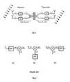
- It is known that the link's power budget of a radio communication device is greatly enhanced when beamforming is used. As shown in
Fig.1 , beamforming involves the use of multiple antennas (as in a phased array). In a transmitter the signal is first distributed over the antennas and then delayed (or phase shifted), where the delay defines the direction of signal transmission, while in the receiver the signal in each antenna path is first delayed, where the delay depends on the direction of reception, and then combined. It is the task of the beamformer to create these delays and add them to the signals of the respective antenna paths. - In the case of narrowband radio communication the delays can be approximated by phase shifts. To realize these phase shifts, circuits called phase shifters (or beamformers) are implemented, operating in one of the major domains of a radio device as shown in
Fig.2 . That is, in the radio frequency (RF) domain, in the local oscillator (LO) domain, in the intermediate frequency (IF) domain (not shown in the figure) or in the baseband (BB) domain. In case of a direct-conversion system, the IF domain does not exist; phase shifters are then provided in at least two of the other domains. In any case, the antenna-referred phase shift has to have a range of 360 degrees, to be able to realize any direction of transmission. - Beamforming (BF) applied directly at the radio frequency (RF) (
Fig. 2a ) offers the benefit that the duplication of the different signal operations in a transceiver is kept to a minimum. However, in semiconductor technologies, e.g. in digital CMOS, beamforming at radio frequencies yields high losses which, in addition, depend on the required phase shift. Moreover, this approach is sensitive to small layout parasitics. These disadvantages render the current RF beamforming techniques not suitable for low noise and ultra-low power radios. - In LO phase shifting (
Fig. 2b ) the phase shift is applied to the LO signal and not in the signal path. In a receiver the high-frequency signal is down-converted with a LO signal that is phase shifted with respect to the LO signals for the other antenna paths. Therefore, multiplication of the LO paths is required, as every mixer in each antenna path needs to be steered by a phase shifted version of the LO signal. After down-conversion, the signals of the different antenna paths are in phase and they can be combined, yielding a signal quality improvement. The implementation in the transmitter requires a split of the signals over the different antenna paths before up-conversion. Then, in each antenna path an up-conversion is performed with a LO signal that is phase shifted with respect to the LO signals in the other antenna paths. Compared to beamforming at radio frequencies (RF), beamforming in the LO path implies a duplication of the down-conversion or up-conversion mixers and routing of the LO signal to the different phase shifters. Just as with RF beamforming, high-frequency power hungry phase shifters are needed, but the noise and gain requirements are alleviated. Again, due to the elevated power consumption, this LO beamforming technique is not suitable for low noise and ultra-low power radio application. - In baseband beamforming the beamforming in the baseband (BB) path can be implemented in analog or digital domain. In analog baseband beamforming (
Fig. 2c ) in systems featuring in-phase and quadrature signalling, the phase-shift adjustment is performed by implementing the operation of matrix rotation of the constellation on a complex plane. The rotation of constellation is equivalent to phase shift when the signal is translated to RF domain (up/down-converted). This operation can be implemented with a set of variable-gain amplifiers, where the rotation of the complex constellation plane is controlled by varying the gain factors of the amplifiers. The beamforming in the digital baseband path (not shown in the figure) can be implemented following the same principle. However, this requires duplication of the complete analog functionality of a radio (filters, variable-gain amplifiers, ADCs) over all antenna paths, as for every antenna path a dedicated digital path is necessary together with a dedicated digital/analog converter. This in turn leads to excessive power consumption. - For wireless communication at high data rates the 57-66 GHz frequency band is allocated. Transceivers for such communication can advantageously be implemented using highly downscaled CMOS.
- In comparison to the RF and LO beamforming implementations, the BB beamforming is the most suitable for CMOS implementations, as it offers improved flexibility, reduced power consumption and area. However, the BB beamforming scenario is not suitable for simple transmission schemes, for example binary phase shift keying (BPSK) and on-off keying (OOK) schemes, where only in-phase signals are used, because it is specifically suited for operation with a quadrature signal, i.e. a signal with in-band (I) and quadrature (Q) components. Moreover, the introduction of variable-gain amplifiers and signal combiners into the baseband path inevitably reduces the signal quality.
- To combat the issues of implementing a full-range phase shifter, a combination of a quadrant selection (coarse phase tuning) using phase-shift local oscillator and fine phase-shifting using RF phase shifters technique has been proposed by Chu et al. ("CMOS phase-shifting circuits for wireless beamforming transmitters", Analog Integrated Circuits and Signal Processing, 2008, Vol. 54 (1), pp. 45-54). However, the proposed hybrid beamforming scheme still suffers from high power consumption, high complexity of the circuit, which in turn brings high influence on the quality of the processed signal, and therefore high signal distortion.
- Application
WO2010/085854 discloses a hybrid adaptive antenna array comprising a number of digital branches that each include an analogue beamforming sub-array. Each sub-array contains a phase shifter adapted to apply a phase shift to the signal from each antenna element. The applied phase shift can take any value in the range from 0° to 360°. A combiner then combines the phase-shifted signals. Each digital branch also includes a signal chain adapted to convert the output of the sub-array to baseband. Finally, a digital processing module is available to estimate phase angles of each chain and produce correction coefficients for the abovementioned phase shifters. Moreover, the digital processing module combines the signals from multiple chains. However, the proposed solution requires complete functionality of phase shifters before the signal is downconverted, therefore suffering from large power consumption, signal degradation, and all drawbacks of a traditional RF phase shifting system. This combination of conventional RF phase shifting and signal combination in digital processing module, however, can easily lead to excessive power consumption. - In the paper"A Four-Channel Beamforming Down-Converter in. 90-nm CMOS Utilizing Phase-Oversampling" (R. Tseng et al., IEEE Journal of Solid-State Circuits, Vol.45, No.11, pp.2262-2272 November 2010) a direct conversion down-converting scheme is presented. Vector-modulators in each channel multiply the inputs with complex beamforming weights before summing contributions from the various channels. The vector modulators are based on a phase-oversampling technique that allows synthesis of linear, high-resolution complex gains without complex variable gain amplifiers. A bank of passive mixers driven by a multiphase local oscillator in each modulator performs phase shifting with a selected value from a set of given phase shifting values. The resulting signals are next combined according to a complex digital algorithm to generate an in-phase and quadrature output. However, this approach requires a multitude of mixers loading the RF chain, with the number of mixers dependent on the required phase resolution. In RF or mm-wave applications it is generally profitable to reduce the number of mixers to minimum. Moreover, the complexity (and hence power consumption) of the multiphase generator also depends on the required phase resolution. Finally, because of the principle of vector combination of signals with fixed phase differences, the output signal amplitude is heavily variable, with the variations being dependent on the available phase resolution. This output signal amplitude variation means that only a few vector combinations are useful for practical application.
- Application
EP0646982 discloses a phased array system that combines in each antenna branch phase shifting in baseband and LO domains. The objective is to allow the use of true time delay signals at different frequencies, and for this the two phase shifters have a full phase shifting range and maximum resolution. There is no hint towards using limited-phase range or low-resolution phase shifting in any of said two domains. - It is apparent from the above, that conventional beamforming techniques suffer from high complexity, high power consumption and usually high signal quality degradation. This is mostly because a complex circuit is inserted in the path of the signal. Often, such circuit is implemented so that it introduces losses to the path, inevitably increasing noise and requiring additional amplification. Even if the phase shifting circuitry is not placed in the signal path, but in the path of the local oscillator, the requirement of full phase shifting range brings higher power consumption, area consumption and complexity.
- Hence, there is a need for solutions for performing beamforming wherein these problems are overcome.
- It is an object of embodiments of the present invention to provide for a hybrid beamforming for a communication device with improved performance. The improvement can be realised in one or more of the following ways : a reduction of power consumption, signal degradation and/or area cost. However, in alternative embodiments the improvement can be realised with respect to yet other performance measures. The presented hybrid beamforming approach is also suitable for communication devices implemented using, but not limited to, CMOS technologies and/or technologies which require high scalability.
- The above objective is accomplished by the solution according to the present invention.
- The invention discloses a method for performing hybrid beamforming in a wireless communication device or any device that uses signal phase shifting for transmission/reception. The method comprises performing phase shifting in at least two different domains (or paths), each characterized by an operational frequency, in the communication device. More in particular, the invention relates in a first aspect to a method for performing at a receiver beamforming on a beam of incoming signals received via plurality of antenna paths according to
claim 1 or 2. - In a second aspect the invention discloses a method for performing hybrid beamforming at a transmitter device, wherein also phase shifting in at least two different domains is performed. More in particular, the invention also relates to a method for performing at a transmitter device beamforming on a beam of outgoing signals via a plurality of antenna paths according to claim 3 or 4.
- The invention proposes performing beamforming in at least two different domains, therefore it is called hybrid beamforming.
- In a preferred embodiment the baseband signal phase shifting step is performed on an analog signal. Alternatively, it can be performed on a digital signal.
- In an advantageous embodiment the method further comprises an intermediate step of mixing with a further local oscillator signal, thereby obtaining a signal at intermediate frequency. Depending on whether the step is performed at the transmitter or receiver side the mixing occurs with a phase shifted baseband signal or with a signal at a radio frequency that possibly has already undergone a phase shift.
- Optionally, in that intermediate step also an additional phase shift operation is performed.
- In the preferred embodiment phase shifting is performed with a reduced resolution (i.e. performing phase adjustment with coarse steps) within a complete phase-shifting range or with high resolution within a limited phase-shifting range (i.e. performing phase adjustments with fine steps). This results in performing the phase correction in multiple beamforming stages, wherein at the first stage the phase is shifted with a fine precision within a limited range, and in the second stage the phase is fully adjusted with a coarse precision in the complete phase-shifting range, or vice versa. Combined, the multiple phase shifting adjustments form a hybrid phase shifting, delivering the same phase shifting performance at lower power consumption, lower implementation complexity of the phase shifters and lower signal degradation.
- Other aspects of the present invention relate to communication devices employing hybrid beamforming. To be more precise, in a third aspect the invention relates to a receiver structure for receiving a beam of incoming signals according to claim 10 or 11.
- In a fourth aspect the invention relates to a structure for transmitting a beam of outgoing signals via a plurality of antenna paths according to claim 12 or 13.
- The transmitter or receiver structure comprises in a preferred embodiment further mixing means arranged for mixing with a further local oscillator signal to produce a signal at intermediate frequency. Optionally further phase shifting means can be provided.
- In another embodiment the receiver or transmitter structure as described comprises a multiplication means for transforming a signal with given frequency into a signal at a multiple of the given frequency. In case phase shifting is applied in the local oscillator path, the phase shifting means can be positioned either before or after the multiplication means, i.e. phase shifting can be performed on the local oscillator signal before or after multiplication.
- The above and other aspects of the invention will be apparent from and elucidated with reference to the embodiment(s) described hereinafter.
- The invention will now be described further, by way of example, with reference to the accompanying drawings, wherein like reference numerals refer to like elements in the various figures.
Fig.1 illustrates the conventional concept of beamforming.Fig.2(a), (b) and(c) illustrate wireless receiver structures using conventional beamforming techniques.Fig.3 illustrates one example of a wireless receiver in accordance with an embodiment of the present invention.Fig.4 illustrates an approach according to the present invention.Fig.4A is for the transmitter side andFig.4B for the receiver side.Fig.5 illustrates a possible implementation of a baseband beamformer in accordance with an embodiment of the present invention.Fig.6 represents one possible implementation of a radio frequency beamformer in accordance with an embodiment of the present invention.Fig.7(a) illustrates an implementation of a local oscillator beamformer in accordance with an embodiment of the invention.Fig.7(b) illustrates an implementation of a local oscillator beamformer in accordance with another embodiment.Fig.8 illustrates a possible system configuration for implementing hybrid beamforming in a wireless receiver.Fig.9(a) illustrates a concept of fine-grain phase-shifting in accordance with an embodiment of the invention, whileFig.9(b) illustrates a concept of coarse-grain phase-shifting.- The present invention will be described with respect to particular embodiments and with reference to certain drawings but the invention is not limited thereto but only by the claims.
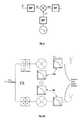
- In embodiments of the present invention a hybrid beamforming scheme is proposed, wherein the beamforming is performed in at least the baseband path and in another domain in the communication device (see
Fig.3 ). For simplicity the figure only a shows schematic system view of a receiver device, and it shall be understood that a transmitter has just an inverse data signal flow. The central component of a system as inFig.3 is a mixer. In the mixer three subsystems meet (electrically, but in fact also physically) : the RF path (between the antenna and the mixer), the LO path (between the phase-locked loop and the mixer) and the baseband (BB) path (between the mixer and the rest of baseband processing chain). The figure illustrates three possible locations for implementing a phase shift, each related to the position with respect to the mixer, i.e. in the signal path at radio frequency (RF), in the local oscillator (LO) path and in the baseband (BB) path. Apart from solutions with direct conversion from RF to baseband, a further option is to use indirect conversion to an IF frequency with phase shifting performed in the IF path. Splitting the phase-shifting in the baseband domain and at least one other domain, provides a simpler circuit implementation, leading to lower power consumption, reduced area and improved signal fidelity (i.e. signal to noise and distortion ratio - SNDR). In preferred embodiments the phase shift is realized in two stages, i.e. with fine-grain phase shifting steps and with coarse-grain phase shifting steps (e.g. by quadrature switching). For example, if one of the phase shifters uses quadrature switching with full phase-shifting range and 90 degrees step, then the range of the fine-grain phase shifter is reduced to less than 90 degrees. That is, if the signal is to be phase-shifted with Z degrees (e.g. 225°), it is first fine-grain shifted by X degrees (45°) and then coarse-grain shifted by Z-X degrees (i.e. 180°). - The proposed hybrid beamforming approach may combine phase-shifting performed in the signal path at radio frequency, i.e. at the RF or LO domain, and in the signal path of baseband frequency, i.e. at the baseband path, i.e. in the receiver, after the down-conversion of the RF signal to BB signal, and in the transmitter before the up-conversion of the BB signal to RF signal.
Fig.4 shows a scheme illustrating an approach according to the present invention.Fig.4A is for the transmitter side andFig.4B for the receiver side. One phase shifting operation (the coarse phase shift) is performed in the baseband domain, while at least a second operation to implement a fine phase shift is performed either in the local oscillator path or in the RF domain. - By splitting the beamforming into multiple stages, i.e. into a coarse-grain (e.g. quadrature switching), and a fine-grain phase-shifting, the hybrid beamforming approach alleviates the disadvantages of both phase-shifting at radio frequency and at baseband frequency when implemented alone.
- In one embodiment, in a hybrid scenario, the phase-shifter in the radio frequency signal path or the local oscillator signal path may perform a fine-grain phase-shifting, i.e. that is adjusting the phase with fine steps of, for example, 5 degrees. Further, the phase-shifting at the radio frequency signal path or the local oscillator signal path may be performed within a limited range, i.e. it may operate only in one quadrant, for example, 0-90 degrees.
- The BB phase shifter may perform a coarse-grain phase adjustment with, for example, a step of 90 degrees (as for example in a quadrature switching implementation), and further, it may operate in a complete phase-shifting range, i.e. 0-360 degrees.
- In certain embodiments the proposed hybrid beamforming scheme is a combination of a local oscillator phase-shifting and a baseband beamforming. When taken alone, both schemes are appealing to be implemented in semiconductor technologies, as explained in the background section. However they have their drawbacks. The LO phase shifting, for example, is very power hungry as it operates at radio frequency (the same applies for the RF beamforming), i.e. 60 GHz, and the baseband phase shifting suffers from reduced dynamic range since the signal path is extended with additional functional blocks. By applying phase shifting in (at least) two domains as in the present disclosure, the benefits that each phase shifting approach offers when implemented alone can be combined, while their disadvantages can be minimized or avoided.
- In other preferred embodiments the hybrid beamforming is implemented as a combination an RF and a BB beamforming.
- The implementation of each of the beamforming techniques in a hybrid beamforming scenario is discussed below, starting with baseband beamforming, which is present in any embodiment of the invention.
- The baseband beamforming can be implemented in the analog or digital domain. The analog baseband phase shifting operates directly on the signals forming the data constellation. In this case, the phase shift is analogous to constellation rotation. Therefore, the analog BB beamforming implements a way of rotating the constellation in opposite direction. This can be seen as implementing a rotation matrix as shown below.

- Conventional implementation of BB beamforming is entirely based on variable gain amplifiers generating the necessary components of the rotation matrix. The main issues with such implementation are:
- (1) the signal path is extended with variable gain amplifiers (VGAs) and signal combiners, yielding reduced signal quality, and
- (2) extensive care has to be taken to make sure that the amplitudes of the output signals are not altered, i.e. the equality

- In the proposed hybrid scenario, only coarse-grain phase shifting, e.g. by means of quadrature switching, at the baseband path needs to be realized. Fine phase tuning is introduced in one of the other signal paths, i.e. RF or LO path. This greatly simplifies the coarse phase shifter implementation. In this case, the phase shifts may be realized by simple switching of the signal lines. In that case, either the polarity of the signals is inverted (resulting in 180° of phase shift), which is achieved by simply swapping the differential lines (I+ with I- or Q+ with Q-), or the I and Q components are swapped, resulting in 90° of phase shift.
Fig.5 shows conceptually an example of the signal swapping action. Here, the swapping operation may be performed by a series of switches which may be operated, for example, by digital gates. Because, the behaviour of this BB phase shifter is purely digital there is no calibration required, as in the case when VGAs are used. Further, such implementation based entirely on switches, the power consumption is practically zero and the signal path is shorter (no VGAs, no buffers), which reduces the signal degradation. - In RF beamforming a phase shift is compensated e.g. by introducing a variable delay in the path by means of switchable transmission lines, each with a different length. This approach implements a true time delay, meaning that the phase shift is progressive with frequency, which is important for a system utilizing very wide signal bandwidth, as the beamformed signal is free of phase distortion. As the total length of the transmission lines has to be equal to the wavelength, the system occupies a large area. Further, introducing longer lines into the signal path introduces signal losses which reduce the signal fidelity and also require compensation by means of additional amplification stages.
- In the proposed hybrid beamforming scenario, the circuitry implementation of a RF phase-shifter is greatly simplified, as it requires circuitry implementation only for a limited phase-shifting range (see
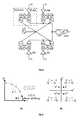
Fig.6 ). As shown in the figure, only two different transmission lines with length of, e.g. λ/8 and λ/16 are required, which allows for adjusting the phase shift with fine steps of λ/16 within a limited range, e.g. 0-90 degrees. Such implementation improves the power consumption and reduces the area cost significantly. Further, the path losses, hence the signal degradation, are minimized as the number of switches operating at radio frequency is minimized as well. Instead of adapting the transmission line lengths various other solutions are available in the art to realise phase shifting in the RF path, which can readily be applied in the proposed approach. - The phase shifts in the LO path can be implemented by introducing small delays on the LO signal, which may be generated by any conventional voltage-controlled oscillator (VCO), an injection locked VCO or by a sub-harmonic injection locked VCO. In the case of a conventional VCO (
Fig. 7a ), small delays are introduced directly in the radio-frequency signal (i.e. 60 GHz), while for the sub-harmonic injection locked VCO (Fig. 7b ), small delays are introduced in the intermediate frequency (IF) signal (e.g. 12 GHz) used for the sub-harmonic locking of the VCO, i.e. the beamformer block (ϕ/τ) is placed before the IF signal upscaling to RF. In case the RF signal comprises I and Q components a quadrature VCO or a quadrature sub-harmonic injection locked VCO may be used instead. - In the proposed hybrid beamforming scenario, this implies the LO phase shifter may cover only one quadrant of the phase shifting circle (e.g. 0-90 degrees). This means, a fine phase tuning is implemented without extending the signal path while amplitude variations between the phase shifting steps can be neglected. If a quadrature VCO is used, this allows for direct access to the I/Q components of the LO signal. Further, if the LO distribution network is built with a sub-harmonically locked mechanism, the phase shift may be imposed directly on the intermediate frequency signal (
Fig. 7b ), e.g. at 12GHz, that is then multiplied to 60GHz. Hence, the total range of the phase shifts (ϕ/τ) introduced in the intermediate frequency signal is only (12GHz/60GHz) = 18°. This greatly reduces the phase-shifting range, resulting in power savings. - Combined, the phase shifting at radio-frequency (RF, LO) and baseband phase shifting form a hybrid phase shifting delivering the same phase shifting performance at lower power consumption and area costs, simplified circuitry implementation and lower signal degradation.
Fig.8 shows a possible system implementation of the proposed hybrid beamforming in a wireless receiver. The system comprises four identical front-end blocks, wherein hybrid beamforming is realised at the LO path (ϕLO) and at the BB path (ϕBB) in accordance with embodiments of the present invention. The system implements a sub-harmonic injection locked VCO (LO) operating at 12GHz, wherein fine phase tuning is introduced directly in the sub-harmonic signal which is then scaled up to radio frequency by the multiplication block (xN), producing a fine phase shifted LO signal. The fine phase shifted LO signal, which may be buffered in the signal replicator (SR), is then mixed with the signal from the antenna, producing a fine phase shifted BB signal. This BB signal is further coarse phase shifted in the ϕBB. Then, the signals from the different antenna paths are combined. Optionally, the baseband signal may be further low-pass filtered (LPF) and amplified (VGA). Advantageously, the proposed system is also scalable - it is constructed in a way that allows further scaling of the number of antenna paths. Here, the main scalability feature is the creation of an almost standalone 60GHz down-conversion subsystem for each antenna path. Adding additional antenna paths simply requires a repetition of the front-end subsystem.- The total power consumption of the proposed hybrid LO and BB beamforming implementation of this four-path phased array wireless receiver, realized in 90nm GP CMOS technology, is 22mW (4x12GHz LO phase shifter) + 16mW (BB beamformer with signal combiners). A similar, however less optimal, power consumption can be achieved when hybrid RF and BB beamforming is used instead.
- The proposed hybrid beamforming schemes may be implemented, for example, in various semiconductor technologies, such as CMOS, BiCMOS, GaAs and others.
Fig.9 graphically explains the effects of phase shifting in the signal path at radio-frequency (RF, LO) and in the signal path at baseband frequency (BB).Fig.9A shows the fine-grain phase shifting, that may be performed by the proposed RF or LO beamformer. More specifically,Fig. 9a illustrates the specifics of a fine phase tuning in LO path when a sub-harmonic injection locked VCO is used. The phase-shifting is implemented by weighing the I and Q components with different coefficients, both in the range from 0 to 1, such that, when combined, a phase-shift of for example 5 degrees, is achieved. A phase-shift of A degrees (e.g. 15°) is initially introduced in the sub-harmonic signal, which after its conversion to 60GHz, results in phase-shift translation (AI, i.e. 15°x5=75°). This projection comes from the fact that a same delay corresponds to different phase shifts at different frequencies. That is, the scale of projection is proportional to the ratio between the introduced phase shifts at different frequencies. Therefore, the phase shifting range is greatly reduced.Fig. 9b shows how this induced phase shift (AI) can be further translated to cover all four quadrants (AII-AIV) by application of baseband quadrature switching, i.e. by simple negation of either I or Q.- The proposed hybrid phase shifting advantageously leads, among others, to a shorter signal path, and / or lower circuitry complexity, and / or lower power consumption and / or area. It is, therefore suited for a low power phased array.


Claims (16)
- Method for performing beamforming on a beam of incoming signals received via a plurality of antenna paths, comprising the steps of:- generating a local oscillator signal;- performing in each antenna path the steps of:performing a first phase shifting operation with an adjustable phase shift on the respective incoming signal,mixing the output of said first phase shifting operation with said local oscillator signal, thereby obtaining a baseband signal,performing a second phase shifting operation on said baseband signal,whereby said second phase shifting operation has a lower resolution than said first phase shifting operation and whereby said first phase shifting operation is performed with a fine step in a first phase shifting range and said second phase shifting operation is performed with a coarse step in a second phase shifting range larger than said first phase shifting range,said coarse step being substantially equal to the size of said first phase shifting range;- combining the outputs of the second phase shifting operations from the plurality of antenna paths.
- Method for performing beamforming on a beam of incoming signals received via a plurality of antenna paths, comprising the steps of:- generating a local oscillator signal;- performing in each antenna path the steps of:performing a first phase shifting operation with an adjustable phase shift on said local oscillator signal,mixing the respective incoming signal with the output of said first phase shifting operation, thereby obtaining a baseband signal,performing a second phase shifting operation on said baseband signal,whereby said second phase shifting operation has a lower resolution than said first phase shifting operation and whereby said first phase shifting operation is performed with a fine step in a first phase shifting range and said second phase shifting operation is performed with a coarse step in a second phase shifting range larger than said first phase shifting range,said coarse step being substantially equal to the size of said first phase shifting range;- combining the outputs of the second phase shifting operations from the plurality of antenna paths.
- Method for performing beamforming on a beam of outgoing signals via a plurality of antenna paths, comprising the steps of:- distributing a signal to be transmitted into a plurality of baseband signals, each baseband signal further handled in a respective one of said plurality of antenna paths;- generating a local oscillator signal;- performing in each antenna path the steps of:performing a first phase shifting operation on the respective baseband signal,mixing the output of said first phase shifting operation with said local oscillator signal,performing a second phase shifting operation with an adjustable phase shift on the signal resulting from said mixing, thereby obtaining the respective outgoing signal,whereby said second phase shifting operation has a higher resolution than said first phase shifting operation and whereby said first phase shifting operation is performed with a coarse step in a first phase shifting range and said second phase shifting operation is performed with a fine step in a second phase shifting range smaller than said first phase shifting range,said coarse step being substantially equal to the size of said second phase shifting range.
- Method for performing beamforming on a beam of outgoing signals via a plurality of antenna paths, comprising the steps of:- distributing a signal to be transmitted into a plurality of baseband signals, each baseband signal further handled in a respective one of said antenna paths;- generating a local oscillator signal;- performing in each antenna path the steps of:performing a first phase shifting operation on the respective baseband signal,performing a second phase shifting operation with an adjustable phase shift on said local oscillator signal,mixing the output of said first phase shifting operation with the output of said second phase shifting operation, thereby obtaining the respective outgoing signal,whereby said second phase shifting operation has a higher resolution than said first phase shifting operation and whereby said first phase shifting operation is performed with a coarse step in a first phase shifting range and said second phase shifting operation is performed with a fine step in a second phase shifting range smaller than said first phase shifting range, said coarse step being substantially equal to the size of said second phase shifting range.
- Method for performing beamforming as in any of the claims 1-4, wherein the signal for baseband signal phase shifting is analog.
- Method for performing beamforming as in any of the claims 1-4, wherein the signal for baseband signal phase shifting is digital.
- Method for performing beamforming as in any of the previous claims, further comprising an intermediate step of mixing with a further local oscillator signal, thereby obtaining a signal at intermediate frequency.
- Method for performing beamforming as in claim 7, whereby in said intermediate step also a phase shifting operation is performed.
- Method for performing beamforming as in claim any of the previous claims, wherein only the range from 0 to 90 degrees is covered in the one of the first and second phase shifting operations with higher resolution.
- Receiver structure for receiving a beam of incoming signals, said receiver structure comprising:- a local oscillator for generating a local oscillator signal;- a plurality of antenna paths, each antenna path arranged for handling one of the incoming signals and each antenna path comprising:first phase shifting means arranged for performing an adjustable first phase shift on the respective incoming signal, mixing means arranged for mixing the output of said first phase shift of said first phase shifting means with said local oscillator signal, thereby obtaining a baseband signal,second phase shifting means connected to said mixing means and arranged for performing a second phase shift on said baseband signal with a resolution lower than that of said first phase shift of said first phase shifting means, whereby said first phase shift is configured to have a fine step in a first phase shifting range and said second phase shift is configured to have a coarse step in a second phase shifting range larger than said first phase shifting range,
said coarse step being substantially equal to the size of said first
phase shifting range;- said receiver structure further comprising signal combination means in connection with said antenna paths and arranged for combining the outputs of said second phase shifts of said second phase shifting means. - Receiver structure for receiving a beam of incoming signals, said receiver structure comprising:- a local oscillator for generating a local oscillator signal;- a plurality of antenna paths, each antenna path arranged for handling one of the incoming signals and each antenna path comprising:first phase shifting means arranged for performing an adjustable first phase shift on said local oscillator signal,mixing means arranged for mixing the respective incoming signal with the output of said first phase shift of said first phase shifting means, thereby obtaining a baseband signal,second phase shifting means connected to said mixing means and arranged for performing a second phase shift on said baseband signalwith a resolution lower than that of said first phase shift of said first phase shifting means,whereby said first phase shift is configured to have a fine step in a first phase shifting range and said second phase shift is configured to have a coarse step in a second phase shifting range larger than said first phase shifting range,said coarse step being substantially equal to the size of said first phase shifting range;- said receiver structure further comprising signal combination means in connection with said antenna paths and arranged for combining the outputs of said second phase shifts of said second phase shifting means.
- Transmitter structure for transmitting a beam of outgoing signals via a plurality of antenna paths, said transmitter structure comprising:- a local oscillator for generating a local oscillator signal;- distributing means arranged for splitting a signal to be transmitted into a plurality of baseband signals;- each antenna path arranged for handling one of said baseband signals and comprising:first phase shifting means arranged for performing a first phase shift on the respective baseband signal,mixing means arranged for mixing the output of said first phase shift of said first phase shifting means with said local oscillator signal,second phase shifting means arranged for performing an adjustable second phase shift on the signal output by said mixing meanswith a resolution higher than that of said first phase shift of said first phase shifting means, thereby obtaining the respective outgoing signal,whereby said first phase shift is configured to have a coarse step in a first phase shifting range and said second phase shift is configured to have a fine step in a second phase shifting range smaller than said first phase shifting range,said coarse step being substantially equal to the size of said second phase shifting range.
- Transmitter structure for transmitting a beam of outgoing signals via a plurality of antenna paths, said transmitter structure comprising:- a local oscillator for generating a local oscillator signal;- distributing means arranged for splitting a signal to be transmitted into a plurality of baseband signals;- each antenna path arranged for handling one of said baseband signals and comprising:with a resolution higher than that of said first phase shift of said first phase shifting means, thereby obtaining the respective outgoing signal,first phase shifting means arranged for performing a first phase shift on the respective baseband signal,second phase shifting means arranged for performing an adjustable second phase shift on said local oscillator signal,mixing means arranged for mixing the output of said first phase shift of said first phase shifting means with the output of said second phase shift of said second phase shifting means,
whereby said first phase shift is configured to have a coarse step in a first phase shifting range and said second phase shift is configured to have a fine step in a second phase shifting range smaller than said first phase shifting range, said coarse step being substantially equal to the size of said second phase shifting range. - Receiver structure as in claim 10 or 11 or transmitter structure as in claim 12 or 13, comprising multiplication means for transforming said local oscillator signal with a given frequency into a local oscillator signal at a multiple of said given frequency.
- Receiver structure as in claim 10 or 11 or transmitter structure as in claim 12 or 13, comprising further mixing means arranged for mixing with a further local oscillator signal to produce a signal at intermediate frequency.
- Receiver structure or transmitter structure as in claim 15 comprising further phase shifting means.
Applications Claiming Priority (1)
| Application Number | Priority Date | Filing Date | Title |
|---|---|---|---|
| US201161548405P | 2011-10-18 | 2011-10-18 |
Publications (2)
| Publication Number | Publication Date |
|---|---|
| EP2584651A1 EP2584651A1 (en) | 2013-04-24 |
| EP2584651B1true EP2584651B1 (en) | 2015-07-01 |
Family
ID=47471461
Family Applications (1)
| Application Number | Title | Priority Date | Filing Date |
|---|---|---|---|
| EP12188608.9AActiveEP2584651B1 (en) | 2011-10-18 | 2012-10-16 | Method for beamforming and device using the same |
Country Status (3)
| Country | Link |
|---|---|
| US (1) | US9184499B2 (en) |
| EP (1) | EP2584651B1 (en) |
| JP (1) | JP6166524B2 (en) |
Families Citing this family (24)
| Publication number | Priority date | Publication date | Assignee | Title |
|---|---|---|---|---|
| US9041602B2 (en)* | 2011-11-14 | 2015-05-26 | Earl W. McCune, Jr. | Phased array transmission methods and apparatus |
| US9130277B2 (en) | 2012-02-27 | 2015-09-08 | Qualcomm Incorporated | RF baseband beamforming |
| US8942299B2 (en)* | 2012-02-27 | 2015-01-27 | Qualcomm Incorporated | Baseband beamforming |
| US9008222B2 (en)* | 2012-08-14 | 2015-04-14 | Samsung Electronics Co., Ltd. | Multi-user and single user MIMO for communication systems using hybrid beam forming |
| US9666942B2 (en)* | 2013-03-15 | 2017-05-30 | Gigpeak, Inc. | Adaptive transmit array for beam-steering |
| US20140334564A1 (en)* | 2013-05-09 | 2014-11-13 | Samsung Electronics Co., Ltd | Method and system for providing low-complexity hybrid precoding in wireless communication systems |
| KR102130294B1 (en) | 2014-04-02 | 2020-07-08 | 삼성전자주식회사 | Method and apparatus for single stream multi-beam transmission and reception in wireless communication system |
| US10027389B2 (en)* | 2015-07-13 | 2018-07-17 | Samsung Electronics Co., Ltd. | Hybrid precoding design for multiple input multiple output system with few-bit analog to digital converters |
| JP6466275B2 (en)* | 2015-07-22 | 2019-02-06 | 株式会社Nttドコモ | Phased array antenna |
| US10756798B2 (en) | 2016-08-04 | 2020-08-25 | Telefonaktiebolaget Lm Ericsson (Publ) | Method and transmitter for transmit beamforming in a wireless communication system |
| US10469091B2 (en)* | 2017-09-21 | 2019-11-05 | Qualcomm Incorporated | Variable delay |
| US20200266879A1 (en) | 2017-09-22 | 2020-08-20 | Kathrein Se | Repeater for Relaying Telecommunications Signals |
| EP3794738A1 (en)* | 2018-05-16 | 2021-03-24 | Telefonaktiebolaget LM Ericsson (publ) | Configuring a beam direction of a set of antennas |
| KR102019082B1 (en)* | 2018-10-08 | 2019-09-06 | (주)엑스엠더블유 | Four Channel Precise Phase Control Apparatus for mmWave Beamforming |
| WO2020132611A1 (en)* | 2018-12-20 | 2020-06-25 | California Institute Of Technology | Spatial redistributors and methods of redistributing mm-wave signals |
| JP7404680B2 (en) | 2019-07-11 | 2023-12-26 | 富士通株式会社 | Beamforming device and beamforming method |
| KR102775992B1 (en)* | 2019-10-14 | 2025-03-10 | 삼성전자주식회사 | Mixer having a phase shift function and a communication device including the same |
| WO2021201735A1 (en)* | 2020-04-02 | 2021-10-07 | Telefonaktiebolaget Lm Ericsson (Publ) | Method and transmitter for analog beam steering |
| CN116075978A (en) | 2020-07-17 | 2023-05-05 | 加州理工学院 | Optical Synchronized Phased Array |
| KR102535454B1 (en)* | 2020-12-29 | 2023-05-26 | 포항공과대학교 산학협력단 | Phase shift method using phase shifter and frequency multiplier and apparatus for performing the same |
| WO2022146037A1 (en) | 2020-12-29 | 2022-07-07 | 포항공과대학교 산학협력단 | Phase shift method using phase shifter and frequency quadrupler, and device performing same |
| US12289147B2 (en) | 2021-11-18 | 2025-04-29 | California Institute Of Technology | Array shape reconstruction for distributed systems |
| US20230170959A1 (en)* | 2021-12-01 | 2023-06-01 | Mediatek Inc. | Method and apparatus for hybrid beamforming with autonomous beamformers in mobile communications |
| EP4246816B1 (en) | 2022-03-18 | 2025-08-20 | Imec VZW | Phased array transceiver element |
Citations (1)
| Publication number | Priority date | Publication date | Assignee | Title |
|---|---|---|---|---|
| EP0646982A1 (en)* | 1993-09-30 | 1995-04-05 | Hughes Aircraft Company | Frequency translation of true time delay signals |
Family Cites Families (8)
| Publication number | Priority date | Publication date | Assignee | Title |
|---|---|---|---|---|
| JPH0290804A (en)* | 1988-09-28 | 1990-03-30 | Mitsubishi Electric Corp | antenna device |
| FR2651609B1 (en)* | 1989-09-01 | 1992-01-03 | Thomson Csf | POINT CONTROL FOR AN ELECTRONIC SCANNING ANTENNA SYSTEM AND BEAM FORMATION THROUGH THE CALCULATION. |
| JPH10178313A (en)* | 1996-12-19 | 1998-06-30 | Mitsubishi Electric Corp | Antenna device |
| US6745020B2 (en) | 2002-08-29 | 2004-06-01 | Eugene Rzyski | Direct downconversion receiver |
| US7904117B2 (en) | 2005-08-12 | 2011-03-08 | Sibeam | Wireless communication device using adaptive beamforming |
| US8195118B2 (en) | 2008-07-15 | 2012-06-05 | Linear Signal, Inc. | Apparatus, system, and method for integrated phase shifting and amplitude control of phased array signals |
| EP2392048B1 (en)* | 2009-02-02 | 2018-10-31 | Commonwealth Scientific and Industrial Research Organisation | Hybrid adaptive antenna array |
| EP2267919B1 (en) | 2009-06-23 | 2012-11-07 | Imec | EHF wireless communication receiver using beamforming with scalable number of antenna paths |
- 2012
- 2012-10-16EPEP12188608.9Apatent/EP2584651B1/enactiveActive
- 2012-10-17USUS13/654,090patent/US9184499B2/enactiveActive
- 2012-10-18JPJP2012230692Apatent/JP6166524B2/enactiveActive
Patent Citations (1)
| Publication number | Priority date | Publication date | Assignee | Title |
|---|---|---|---|---|
| EP0646982A1 (en)* | 1993-09-30 | 1995-04-05 | Hughes Aircraft Company | Frequency translation of true time delay signals |
Also Published As
| Publication number | Publication date |
|---|---|
| EP2584651A1 (en) | 2013-04-24 |
| US9184499B2 (en) | 2015-11-10 |
| JP2013118620A (en) | 2013-06-13 |
| JP6166524B2 (en) | 2017-07-19 |
| US20130093624A1 (en) | 2013-04-18 |
Similar Documents
| Publication | Publication Date | Title |
|---|---|---|
| EP2584651B1 (en) | Method for beamforming and device using the same | |
| CN103716080B (en) | Phased array emitter, receiver and its method | |
| US11621757B2 (en) | System and method for a multi-beam beamforming front-end architecture for wireless transceivers | |
| US11601183B2 (en) | Spatial redistributors and methods of redistributing mm-wave signals | |
| US7502631B2 (en) | Monolithic silicon-based phased arrays for communications and radars | |
| US7493144B2 (en) | Multi-element phased array transmitter with LO phase shifting and integrated power amplifier | |
| US8195118B2 (en) | Apparatus, system, and method for integrated phase shifting and amplitude control of phased array signals | |
| JP5677697B2 (en) | Active phased array architecture | |
| US10862459B2 (en) | Low-loss vector modulator based phase shifter | |
| US10374308B2 (en) | Signal distribution network | |
| US10763940B2 (en) | Digital port expansion for hybrid massive MIMO systems | |
| US10665958B2 (en) | Beamforming receiver | |
| US9425505B2 (en) | Integrated phase-shifting-and-combining circuitry to support multiple antennas | |
| US10411875B2 (en) | Hybrid type transceiver for broadband large area beamforming | |
| EP4246816B1 (en) | Phased array transceiver element | |
| US12381316B2 (en) | Frequency tunable bi-directional active phased-array processing | |
| Gueorguiev et al. | A 5.2 GHz CMOS I/Q modulator with integrated phase shifter for beamforming | |
| US12445226B2 (en) | Scalable decentralized redistributor and method of redistributing signals | |
| Krishnaswamy et al. | Integrated beamforming arrays | |
| US20210105092A1 (en) | Scalable Decentralized Redistributor and Method of Redistributing Signals | |
| Shalu et al. | CMOS Scaled Architecture and Circuit Choices for 5G | |
| Yang et al. | Variable periphery amplifier with built-in phase shifting capability for ultra compact transceiver module | |
| JPH07162223A (en) | Antenna circuit |
Legal Events
| Date | Code | Title | Description |
|---|---|---|---|
| PUAI | Public reference made under article 153(3) epc to a published international application that has entered the european phase | Free format text:ORIGINAL CODE: 0009012 | |
| AK | Designated contracting states | Kind code of ref document:A1 Designated state(s):AL AT BE BG CH CY CZ DE DK EE ES FI FR GB GR HR HU IE IS IT LI LT LU LV MC MK MT NL NO PL PT RO RS SE SI SK SM TR | |
| AX | Request for extension of the european patent | Extension state:BA ME | |
| 17P | Request for examination filed | Effective date:20130806 | |
| RBV | Designated contracting states (corrected) | Designated state(s):AL AT BE BG CH CY CZ DE DK EE ES FI FR GB GR HR HU IE IS IT LI LT LU LV MC MK MT NL NO PL PT RO RS SE SI SK SM TR | |
| 17Q | First examination report despatched | Effective date:20140116 | |
| GRAP | Despatch of communication of intention to grant a patent | Free format text:ORIGINAL CODE: EPIDOSNIGR1 | |
| INTG | Intention to grant announced | Effective date:20150126 | |
| GRAS | Grant fee paid | Free format text:ORIGINAL CODE: EPIDOSNIGR3 | |
| GRAA | (expected) grant | Free format text:ORIGINAL CODE: 0009210 | |
| RIN1 | Information on inventor provided before grant (corrected) | Inventor name:RACZKOWSKI, JAKUB Inventor name:WAMBACQ, PIET | |
| AK | Designated contracting states | Kind code of ref document:B1 Designated state(s):AL AT BE BG CH CY CZ DE DK EE ES FI FR GB GR HR HU IE IS IT LI LT LU LV MC MK MT NL NO PL PT RO RS SE SI SK SM TR | |
| REG | Reference to a national code | Ref country code:GB Ref legal event code:FG4D | |
| REG | Reference to a national code | Ref country code:AT Ref legal event code:REF Ref document number:734450 Country of ref document:AT Kind code of ref document:T Effective date:20150715 Ref country code:CH Ref legal event code:EP | |
| REG | Reference to a national code | Ref country code:IE Ref legal event code:FG4D | |
| REG | Reference to a national code | Ref country code:DE Ref legal event code:R096 Ref document number:602012008342 Country of ref document:DE | |
| REG | Reference to a national code | Ref country code:FR Ref legal event code:PLFP Year of fee payment:4 | |
| REG | Reference to a national code | Ref country code:AT Ref legal event code:MK05 Ref document number:734450 Country of ref document:AT Kind code of ref document:T Effective date:20150701 | |
| REG | Reference to a national code | Ref country code:NL Ref legal event code:MP Effective date:20150701 | |
| REG | Reference to a national code | Ref country code:LT Ref legal event code:MG4D | |
| PG25 | Lapsed in a contracting state [announced via postgrant information from national office to epo] | Ref country code:NO Free format text:LAPSE BECAUSE OF FAILURE TO SUBMIT A TRANSLATION OF THE DESCRIPTION OR TO PAY THE FEE WITHIN THE PRESCRIBED TIME-LIMIT Effective date:20151001 Ref country code:GR Free format text:LAPSE BECAUSE OF FAILURE TO SUBMIT A TRANSLATION OF THE DESCRIPTION OR TO PAY THE FEE WITHIN THE PRESCRIBED TIME-LIMIT Effective date:20151002 Ref country code:LV Free format text:LAPSE BECAUSE OF FAILURE TO SUBMIT A TRANSLATION OF THE DESCRIPTION OR TO PAY THE FEE WITHIN THE PRESCRIBED TIME-LIMIT Effective date:20150701 Ref country code:FI Free format text:LAPSE BECAUSE OF FAILURE TO SUBMIT A TRANSLATION OF THE DESCRIPTION OR TO PAY THE FEE WITHIN THE PRESCRIBED TIME-LIMIT Effective date:20150701 Ref country code:LT Free format text:LAPSE BECAUSE OF FAILURE TO SUBMIT A TRANSLATION OF THE DESCRIPTION OR TO PAY THE FEE WITHIN THE PRESCRIBED TIME-LIMIT Effective date:20150701 | |
| PG25 | Lapsed in a contracting state [announced via postgrant information from national office to epo] | Ref country code:ES Free format text:LAPSE BECAUSE OF FAILURE TO SUBMIT A TRANSLATION OF THE DESCRIPTION OR TO PAY THE FEE WITHIN THE PRESCRIBED TIME-LIMIT Effective date:20150701 Ref country code:HR Free format text:LAPSE BECAUSE OF FAILURE TO SUBMIT A TRANSLATION OF THE DESCRIPTION OR TO PAY THE FEE WITHIN THE PRESCRIBED TIME-LIMIT Effective date:20150701 Ref country code:IS Free format text:LAPSE BECAUSE OF FAILURE TO SUBMIT A TRANSLATION OF THE DESCRIPTION OR TO PAY THE FEE WITHIN THE PRESCRIBED TIME-LIMIT Effective date:20151101 Ref country code:PT Free format text:LAPSE BECAUSE OF FAILURE TO SUBMIT A TRANSLATION OF THE DESCRIPTION OR TO PAY THE FEE WITHIN THE PRESCRIBED TIME-LIMIT Effective date:20151102 Ref country code:AT Free format text:LAPSE BECAUSE OF FAILURE TO SUBMIT A TRANSLATION OF THE DESCRIPTION OR TO PAY THE FEE WITHIN THE PRESCRIBED TIME-LIMIT Effective date:20150701 Ref country code:SE Free format text:LAPSE BECAUSE OF FAILURE TO SUBMIT A TRANSLATION OF THE DESCRIPTION OR TO PAY THE FEE WITHIN THE PRESCRIBED TIME-LIMIT Effective date:20150701 Ref country code:PL Free format text:LAPSE BECAUSE OF FAILURE TO SUBMIT A TRANSLATION OF THE DESCRIPTION OR TO PAY THE FEE WITHIN THE PRESCRIBED TIME-LIMIT Effective date:20150701 Ref country code:RS Free format text:LAPSE BECAUSE OF FAILURE TO SUBMIT A TRANSLATION OF THE DESCRIPTION OR TO PAY THE FEE WITHIN THE PRESCRIBED TIME-LIMIT Effective date:20150701 | |
| REG | Reference to a national code | Ref country code:DE Ref legal event code:R097 Ref document number:602012008342 Country of ref document:DE | |
| PG25 | Lapsed in a contracting state [announced via postgrant information from national office to epo] | Ref country code:IT Free format text:LAPSE BECAUSE OF FAILURE TO SUBMIT A TRANSLATION OF THE DESCRIPTION OR TO PAY THE FEE WITHIN THE PRESCRIBED TIME-LIMIT Effective date:20150701 Ref country code:EE Free format text:LAPSE BECAUSE OF FAILURE TO SUBMIT A TRANSLATION OF THE DESCRIPTION OR TO PAY THE FEE WITHIN THE PRESCRIBED TIME-LIMIT Effective date:20150701 Ref country code:SK Free format text:LAPSE BECAUSE OF FAILURE TO SUBMIT A TRANSLATION OF THE DESCRIPTION OR TO PAY THE FEE WITHIN THE PRESCRIBED TIME-LIMIT Effective date:20150701 Ref country code:DK Free format text:LAPSE BECAUSE OF FAILURE TO SUBMIT A TRANSLATION OF THE DESCRIPTION OR TO PAY THE FEE WITHIN THE PRESCRIBED TIME-LIMIT Effective date:20150701 Ref country code:CZ Free format text:LAPSE BECAUSE OF FAILURE TO SUBMIT A TRANSLATION OF THE DESCRIPTION OR TO PAY THE FEE WITHIN THE PRESCRIBED TIME-LIMIT Effective date:20150701 | |
| PLBE | No opposition filed within time limit | Free format text:ORIGINAL CODE: 0009261 | |
| STAA | Information on the status of an ep patent application or granted ep patent | Free format text:STATUS: NO OPPOSITION FILED WITHIN TIME LIMIT | |
| PG25 | Lapsed in a contracting state [announced via postgrant information from national office to epo] | Ref country code:LU Free format text:LAPSE BECAUSE OF FAILURE TO SUBMIT A TRANSLATION OF THE DESCRIPTION OR TO PAY THE FEE WITHIN THE PRESCRIBED TIME-LIMIT Effective date:20151016 Ref country code:RO Free format text:LAPSE BECAUSE OF FAILURE TO SUBMIT A TRANSLATION OF THE DESCRIPTION OR TO PAY THE FEE WITHIN THE PRESCRIBED TIME-LIMIT Effective date:20150701 | |
| REG | Reference to a national code | Ref country code:CH Ref legal event code:PL | |
| 26N | No opposition filed | Effective date:20160404 | |
| PG25 | Lapsed in a contracting state [announced via postgrant information from national office to epo] | Ref country code:MC Free format text:LAPSE BECAUSE OF FAILURE TO SUBMIT A TRANSLATION OF THE DESCRIPTION OR TO PAY THE FEE WITHIN THE PRESCRIBED TIME-LIMIT Effective date:20150701 | |
| REG | Reference to a national code | Ref country code:IE Ref legal event code:MM4A | |
| PG25 | Lapsed in a contracting state [announced via postgrant information from national office to epo] | Ref country code:CH Free format text:LAPSE BECAUSE OF NON-PAYMENT OF DUE FEES Effective date:20151031 Ref country code:LI Free format text:LAPSE BECAUSE OF NON-PAYMENT OF DUE FEES Effective date:20151031 | |
| PG25 | Lapsed in a contracting state [announced via postgrant information from national office to epo] | Ref country code:SI Free format text:LAPSE BECAUSE OF FAILURE TO SUBMIT A TRANSLATION OF THE DESCRIPTION OR TO PAY THE FEE WITHIN THE PRESCRIBED TIME-LIMIT Effective date:20150701 | |
| REG | Reference to a national code | Ref country code:FR Ref legal event code:PLFP Year of fee payment:5 | |
| PG25 | Lapsed in a contracting state [announced via postgrant information from national office to epo] | Ref country code:IE Free format text:LAPSE BECAUSE OF NON-PAYMENT OF DUE FEES Effective date:20151016 | |
| PG25 | Lapsed in a contracting state [announced via postgrant information from national office to epo] | Ref country code:BE Free format text:LAPSE BECAUSE OF FAILURE TO SUBMIT A TRANSLATION OF THE DESCRIPTION OR TO PAY THE FEE WITHIN THE PRESCRIBED TIME-LIMIT Effective date:20150701 | |
| PG25 | Lapsed in a contracting state [announced via postgrant information from national office to epo] | Ref country code:HU Free format text:LAPSE BECAUSE OF FAILURE TO SUBMIT A TRANSLATION OF THE DESCRIPTION OR TO PAY THE FEE WITHIN THE PRESCRIBED TIME-LIMIT; INVALID AB INITIO Effective date:20121016 Ref country code:BG Free format text:LAPSE BECAUSE OF FAILURE TO SUBMIT A TRANSLATION OF THE DESCRIPTION OR TO PAY THE FEE WITHIN THE PRESCRIBED TIME-LIMIT Effective date:20150701 Ref country code:SM Free format text:LAPSE BECAUSE OF FAILURE TO SUBMIT A TRANSLATION OF THE DESCRIPTION OR TO PAY THE FEE WITHIN THE PRESCRIBED TIME-LIMIT Effective date:20150701 | |
| PG25 | Lapsed in a contracting state [announced via postgrant information from national office to epo] | Ref country code:NL Free format text:LAPSE BECAUSE OF FAILURE TO SUBMIT A TRANSLATION OF THE DESCRIPTION OR TO PAY THE FEE WITHIN THE PRESCRIBED TIME-LIMIT Effective date:20150701 Ref country code:CY Free format text:LAPSE BECAUSE OF FAILURE TO SUBMIT A TRANSLATION OF THE DESCRIPTION OR TO PAY THE FEE WITHIN THE PRESCRIBED TIME-LIMIT Effective date:20150701 | |
| PG25 | Lapsed in a contracting state [announced via postgrant information from national office to epo] | Ref country code:MT Free format text:LAPSE BECAUSE OF FAILURE TO SUBMIT A TRANSLATION OF THE DESCRIPTION OR TO PAY THE FEE WITHIN THE PRESCRIBED TIME-LIMIT Effective date:20150701 | |
| REG | Reference to a national code | Ref country code:FR Ref legal event code:PLFP Year of fee payment:6 | |
| PG25 | Lapsed in a contracting state [announced via postgrant information from national office to epo] | Ref country code:MK Free format text:LAPSE BECAUSE OF FAILURE TO SUBMIT A TRANSLATION OF THE DESCRIPTION OR TO PAY THE FEE WITHIN THE PRESCRIBED TIME-LIMIT Effective date:20150701 Ref country code:TR Free format text:LAPSE BECAUSE OF FAILURE TO SUBMIT A TRANSLATION OF THE DESCRIPTION OR TO PAY THE FEE WITHIN THE PRESCRIBED TIME-LIMIT Effective date:20150701 | |
| REG | Reference to a national code | Ref country code:FR Ref legal event code:PLFP Year of fee payment:7 | |
| PG25 | Lapsed in a contracting state [announced via postgrant information from national office to epo] | Ref country code:AL Free format text:LAPSE BECAUSE OF FAILURE TO SUBMIT A TRANSLATION OF THE DESCRIPTION OR TO PAY THE FEE WITHIN THE PRESCRIBED TIME-LIMIT Effective date:20150701 | |
| P01 | Opt-out of the competence of the unified patent court (upc) registered | Effective date:20230513 | |
| PGFP | Annual fee paid to national office [announced via postgrant information from national office to epo] | Ref country code:GB Payment date:20240919 Year of fee payment:13 | |
| PGFP | Annual fee paid to national office [announced via postgrant information from national office to epo] | Ref country code:FR Payment date:20240919 Year of fee payment:13 | |
| PGFP | Annual fee paid to national office [announced via postgrant information from national office to epo] | Ref country code:DE Payment date:20240919 Year of fee payment:13 |