EP2584044B1 - Electrochemical analyte detections apparatus and method - Google Patents
Electrochemical analyte detections apparatus and methodDownload PDFInfo
- Publication number
- EP2584044B1 EP2584044B1EP12199820.7AEP12199820AEP2584044B1EP 2584044 B1EP2584044 B1EP 2584044B1EP 12199820 AEP12199820 AEP 12199820AEP 2584044 B1EP2584044 B1EP 2584044B1
- Authority
- EP
- European Patent Office
- Prior art keywords
- analyte
- sample
- electrodes
- electrode
- test
- Prior art date
- Legal status (The legal status is an assumption and is not a legal conclusion. Google has not performed a legal analysis and makes no representation as to the accuracy of the status listed.)
- Active
Links
- 239000012491analyteSubstances0.000titleclaimsdescription117
- 238000000034methodMethods0.000titleclaimsdescription13
- 238000001514detection methodMethods0.000titleclaimsdescription8
- 102000004190EnzymesHuman genes0.000claimsdescription123
- 108090000790EnzymesProteins0.000claimsdescription123
- 238000012360testing methodMethods0.000claimsdescription92
- 239000003153chemical reaction reagentSubstances0.000claimsdescription67
- 238000009826distributionMethods0.000claimsdescription45
- 230000027455bindingEffects0.000claimsdescription30
- 239000000126substanceSubstances0.000claimsdescription30
- 239000000758substrateSubstances0.000claimsdescription21
- 238000006073displacement reactionMethods0.000claimsdescription9
- 230000015572biosynthetic processEffects0.000claimsdescription6
- 238000004519manufacturing processMethods0.000claimsdescription6
- 239000003795chemical substances by applicationSubstances0.000claimsdescription5
- 238000011065in-situ storageMethods0.000claimsdescription3
- 229940088598enzymeDrugs0.000description115
- 230000000694effectsEffects0.000description23
- 238000005259measurementMethods0.000description15
- 238000003556assayMethods0.000description14
- 108020003175receptorsProteins0.000description10
- 102000005962receptorsHuman genes0.000description10
- 239000000243solutionSubstances0.000description10
- 108010015776Glucose oxidaseProteins0.000description8
- 239000004366Glucose oxidaseSubstances0.000description8
- WQZGKKKJIJFFOK-VFUOTHLCSA-Nbeta-D-glucoseChemical compoundOC[C@H]1O[C@@H](O)[C@H](O)[C@@H](O)[C@@H]1OWQZGKKKJIJFFOK-VFUOTHLCSA-N0.000description8
- 229940116332glucose oxidaseDrugs0.000description8
- 235000019420glucose oxidaseNutrition0.000description8
- 239000000575pesticideSubstances0.000description8
- WQZGKKKJIJFFOK-GASJEMHNSA-NGlucoseNatural productsOC[C@H]1OC(O)[C@H](O)[C@@H](O)[C@@H]1OWQZGKKKJIJFFOK-GASJEMHNSA-N0.000description7
- 239000008103glucoseSubstances0.000description7
- 239000010410layerSubstances0.000description7
- 108091023037AptamerProteins0.000description6
- 238000006243chemical reactionMethods0.000description6
- 238000003018immunoassayMethods0.000description6
- 150000001875compoundsChemical class0.000description5
- 238000010276constructionMethods0.000description5
- 108091008039hormone receptorsProteins0.000description5
- 239000000463materialSubstances0.000description5
- XLYOFNOQVPJJNP-UHFFFAOYSA-NwaterSubstancesOXLYOFNOQVPJJNP-UHFFFAOYSA-N0.000description5
- 230000001419dependent effectEffects0.000description4
- 230000003993interactionEffects0.000description4
- 150000007523nucleic acidsChemical class0.000description4
- 241000894007speciesSpecies0.000description4
- 230000009870specific bindingEffects0.000description4
- 238000004458analytical methodMethods0.000description3
- 239000000872bufferSubstances0.000description3
- 238000004891communicationMethods0.000description3
- 230000000295complement effectEffects0.000description3
- 230000002596correlated effectEffects0.000description3
- 201000010099diseaseDiseases0.000description3
- 208000037265diseases, disorders, signs and symptomsDiseases0.000description3
- 229940079593drugDrugs0.000description3
- 239000003814drugSubstances0.000description3
- 238000000835electrochemical detectionMethods0.000description3
- NLJMYIDDQXHKNR-UHFFFAOYSA-Ksodium citrateChemical compoundO.O.[Na+].[Na+].[Na+].[O-]C(=O)CC(O)(CC([O-])=O)C([O-])=ONLJMYIDDQXHKNR-UHFFFAOYSA-K0.000description3
- 239000001509sodium citrateSubstances0.000description3
- 102000014914Carrier ProteinsHuman genes0.000description2
- PHOQVHQSTUBQQK-SQOUGZDYSA-ND-glucono-1,5-lactoneChemical compoundOC[C@H]1OC(=O)[C@H](O)[C@@H](O)[C@@H]1OPHOQVHQSTUBQQK-SQOUGZDYSA-N0.000description2
- 108010065556Drug ReceptorsProteins0.000description2
- 238000002965ELISAMethods0.000description2
- 108091028043Nucleic acid sequenceProteins0.000description2
- 108090000854OxidoreductasesProteins0.000description2
- 102000004316OxidoreductasesHuman genes0.000description2
- 108700020962PeroxidaseProteins0.000description2
- 102000003992PeroxidasesHuman genes0.000description2
- 238000004082amperometric methodMethods0.000description2
- 239000000427antigenSubstances0.000description2
- 238000002820assay formatMethods0.000description2
- 108091008324binding proteinsProteins0.000description2
- 210000004369bloodAnatomy0.000description2
- 239000008280bloodSubstances0.000description2
- 230000003197catalytic effectEffects0.000description2
- ZPUCINDJVBIVPJ-LJISPDSOSA-NcocaineChemical compoundO([C@H]1C[C@@H]2CC[C@@H](N2C)[C@H]1C(=O)OC)C(=O)C1=CC=CC=C1ZPUCINDJVBIVPJ-LJISPDSOSA-N0.000description2
- 238000013461designMethods0.000description2
- 235000012209glucono delta-lactoneNutrition0.000description2
- 229960003681gluconolactoneDrugs0.000description2
- 229940088597hormoneDrugs0.000description2
- 239000005556hormoneSubstances0.000description2
- 206010022000influenzaDiseases0.000description2
- 239000000203mixtureSubstances0.000description2
- 108020004707nucleic acidsProteins0.000description2
- 102000039446nucleic acidsHuman genes0.000description2
- -1potassium ferricyanideChemical compound0.000description2
- 238000004313potentiometryMethods0.000description2
- 230000008569processEffects0.000description2
- 108090000765processed proteins & peptidesProteins0.000description2
- 230000001052transient effectEffects0.000description2
- 238000005406washingMethods0.000description2
- 108020005199DehydrogenasesProteins0.000description1
- 102000013138Drug ReceptorsHuman genes0.000description1
- 108010093096Immobilized EnzymesProteins0.000description1
- 108060003951ImmunoglobulinProteins0.000description1
- 108091007187ReductasesProteins0.000description1
- 108090000190ThrombinProteins0.000description1
- 239000012790adhesive layerSubstances0.000description1
- 229940125644antibody drugDrugs0.000description1
- 102000036639antigensHuman genes0.000description1
- 108091007433antigensProteins0.000description1
- 239000011324beadSubstances0.000description1
- 238000009534blood testMethods0.000description1
- 230000008859changeEffects0.000description1
- 229960003920cocaineDrugs0.000description1
- 230000009918complex formationEffects0.000description1
- 230000008878couplingEffects0.000description1
- 238000010168coupling processMethods0.000description1
- 238000005859coupling reactionMethods0.000description1
- 239000007857degradation productSubstances0.000description1
- 238000009792diffusion processMethods0.000description1
- 238000007812electrochemical assayMethods0.000description1
- 238000002848electrochemical methodMethods0.000description1
- 238000001962electrophoresisMethods0.000description1
- 238000011156evaluationMethods0.000description1
- YAGKRVSRTSUGEY-UHFFFAOYSA-NferricyanideChemical compound[Fe+3].N#[C-].N#[C-].N#[C-].N#[C-].N#[C-].N#[C-]YAGKRVSRTSUGEY-UHFFFAOYSA-N0.000description1
- 230000005669field effectEffects0.000description1
- 238000007667floatingMethods0.000description1
- 230000004907fluxEffects0.000description1
- PCHJSUWPFVWCPO-UHFFFAOYSA-NgoldChemical compound[Au]PCHJSUWPFVWCPO-UHFFFAOYSA-N0.000description1
- 239000010931goldSubstances0.000description1
- 229910052737goldInorganic materials0.000description1
- 238000009396hybridizationMethods0.000description1
- 102000018358immunoglobulinHuman genes0.000description1
- 238000003780insertionMethods0.000description1
- 230000037431insertionEffects0.000description1
- 239000004816latexSubstances0.000description1
- 229920000126latexPolymers0.000description1
- 239000003446ligandSubstances0.000description1
- 239000012035limiting reagentSubstances0.000description1
- 239000012528membraneSubstances0.000description1
- 244000005700microbiomeSpecies0.000description1
- 230000003287optical effectEffects0.000description1
- 238000002360preparation methodMethods0.000description1
- 102000004196processed proteins & peptidesHuman genes0.000description1
- 238000000159protein binding assayMethods0.000description1
- 102000004169proteins and genesHuman genes0.000description1
- 108090000623proteins and genesProteins0.000description1
- 238000011158quantitative evaluationMethods0.000description1
- 230000009467reductionEffects0.000description1
- 238000011160researchMethods0.000description1
- 230000027756respiratory electron transport chainEffects0.000description1
- 230000004044responseEffects0.000description1
- 210000003296salivaAnatomy0.000description1
- 229930000044secondary metaboliteNatural products0.000description1
- 230000035945sensitivityEffects0.000description1
- 125000006850spacer groupChemical group0.000description1
- 210000004243sweatAnatomy0.000description1
- 210000001138tearAnatomy0.000description1
- 239000012085test solutionSubstances0.000description1
- 229960004072thrombinDrugs0.000description1
- 238000012546transferMethods0.000description1
Images


Classifications
- G—PHYSICS
- G01—MEASURING; TESTING
- G01N—INVESTIGATING OR ANALYSING MATERIALS BY DETERMINING THEIR CHEMICAL OR PHYSICAL PROPERTIES
- G01N33/00—Investigating or analysing materials by specific methods not covered by groups G01N1/00 - G01N31/00
- G01N33/48—Biological material, e.g. blood, urine; Haemocytometers
- G01N33/50—Chemical analysis of biological material, e.g. blood, urine; Testing involving biospecific ligand binding methods; Immunological testing
- G01N33/53—Immunoassay; Biospecific binding assay; Materials therefor
- G01N33/573—Immunoassay; Biospecific binding assay; Materials therefor for enzymes or isoenzymes
- G—PHYSICS
- G01—MEASURING; TESTING
- G01N—INVESTIGATING OR ANALYSING MATERIALS BY DETERMINING THEIR CHEMICAL OR PHYSICAL PROPERTIES
- G01N33/00—Investigating or analysing materials by specific methods not covered by groups G01N1/00 - G01N31/00
- G01N33/48—Biological material, e.g. blood, urine; Haemocytometers
- G01N33/50—Chemical analysis of biological material, e.g. blood, urine; Testing involving biospecific ligand binding methods; Immunological testing
- G01N33/53—Immunoassay; Biospecific binding assay; Materials therefor
- G01N33/5308—Immunoassay; Biospecific binding assay; Materials therefor for analytes not provided for elsewhere, e.g. nucleic acids, uric acid, worms, mites
- C—CHEMISTRY; METALLURGY
- C12—BIOCHEMISTRY; BEER; SPIRITS; WINE; VINEGAR; MICROBIOLOGY; ENZYMOLOGY; MUTATION OR GENETIC ENGINEERING
- C12Q—MEASURING OR TESTING PROCESSES INVOLVING ENZYMES, NUCLEIC ACIDS OR MICROORGANISMS; COMPOSITIONS OR TEST PAPERS THEREFOR; PROCESSES OF PREPARING SUCH COMPOSITIONS; CONDITION-RESPONSIVE CONTROL IN MICROBIOLOGICAL OR ENZYMOLOGICAL PROCESSES
- C12Q1/00—Measuring or testing processes involving enzymes, nucleic acids or microorganisms; Compositions therefor; Processes of preparing such compositions
- C12Q1/001—Enzyme electrodes
- C—CHEMISTRY; METALLURGY
- C12—BIOCHEMISTRY; BEER; SPIRITS; WINE; VINEGAR; MICROBIOLOGY; ENZYMOLOGY; MUTATION OR GENETIC ENGINEERING
- C12Q—MEASURING OR TESTING PROCESSES INVOLVING ENZYMES, NUCLEIC ACIDS OR MICROORGANISMS; COMPOSITIONS OR TEST PAPERS THEREFOR; PROCESSES OF PREPARING SUCH COMPOSITIONS; CONDITION-RESPONSIVE CONTROL IN MICROBIOLOGICAL OR ENZYMOLOGICAL PROCESSES
- C12Q1/00—Measuring or testing processes involving enzymes, nucleic acids or microorganisms; Compositions therefor; Processes of preparing such compositions
- C12Q1/02—Measuring or testing processes involving enzymes, nucleic acids or microorganisms; Compositions therefor; Processes of preparing such compositions involving viable microorganisms
- C12Q1/04—Determining presence or kind of microorganism; Use of selective media for testing antibiotics or bacteriocides; Compositions containing a chemical indicator therefor
- G—PHYSICS
- G01—MEASURING; TESTING
- G01N—INVESTIGATING OR ANALYSING MATERIALS BY DETERMINING THEIR CHEMICAL OR PHYSICAL PROPERTIES
- G01N27/00—Investigating or analysing materials by the use of electric, electrochemical, or magnetic means
- G01N27/26—Investigating or analysing materials by the use of electric, electrochemical, or magnetic means by investigating electrochemical variables; by using electrolysis or electrophoresis
- G01N27/416—Systems
- G01N27/4166—Systems measuring a particular property of an electrolyte
- G—PHYSICS
- G01—MEASURING; TESTING
- G01N—INVESTIGATING OR ANALYSING MATERIALS BY DETERMINING THEIR CHEMICAL OR PHYSICAL PROPERTIES
- G01N33/00—Investigating or analysing materials by specific methods not covered by groups G01N1/00 - G01N31/00
- G01N33/48—Biological material, e.g. blood, urine; Haemocytometers
- G01N33/50—Chemical analysis of biological material, e.g. blood, urine; Testing involving biospecific ligand binding methods; Immunological testing
- G01N33/53—Immunoassay; Biospecific binding assay; Materials therefor
- G01N33/543—Immunoassay; Biospecific binding assay; Materials therefor with an insoluble carrier for immobilising immunochemicals
- G01N33/54366—Apparatus specially adapted for solid-phase testing
- G01N33/54373—Apparatus specially adapted for solid-phase testing involving physiochemical end-point determination, e.g. wave-guides, FETS, gratings
- G01N33/5438—Electrodes
- G—PHYSICS
- G01—MEASURING; TESTING
- G01N—INVESTIGATING OR ANALYSING MATERIALS BY DETERMINING THEIR CHEMICAL OR PHYSICAL PROPERTIES
- G01N2333/00—Assays involving biological materials from specific organisms or of a specific nature
- G01N2333/90—Enzymes; Proenzymes
- G—PHYSICS
- G01—MEASURING; TESTING
- G01N—INVESTIGATING OR ANALYSING MATERIALS BY DETERMINING THEIR CHEMICAL OR PHYSICAL PROPERTIES
- G01N2333/00—Assays involving biological materials from specific organisms or of a specific nature
- G01N2333/90—Enzymes; Proenzymes
- G01N2333/902—Oxidoreductases (1.)
Definitions
- This applicationrelates to an apparatus and method for electrochemical detection of an analyte in a sample.
- the inventionutilizes a specific binding relationship between the analyte and at least one reagent provided in the apparatus as a means for detecting the analyte.
- an apparatus for determining an analyte in a samplecomprising
- the present inventionprovides a method for determining an analyte in a sample, comprising the steps of:
- the present inventionprovides a new method and apparatus for electrochemical detection of analyte in a sample that makes use of a binding interaction.
- the inventionrelies on the discovery that asymmetric distribution of a redox enzyme between two electrodes that occurs when a redox enzyme-containing reagent is immobilized at the surface of one electrode can be detected as a chemical potential gradient arising from an asymmetry in the distribution of oxidized or reduced redox substrate.
- This chemical potential gradientcan be detected potentiometrically by observing the potential difference between the electrodes in an open circuit, or amperometrically by observing the current flow between the electrodes when the circuit is closed. In both cases, the observation of asymmetry can be done without the application of an external potential or current to the electrodes.
- a sandwich type assayis utilized.
- a sample to be tested for analyteis introduced to a test cell in the presence of a mobile test reagent.
- the test cellcomprises a first and a second electrode.
- the first electrodehas immobilized on the surface thereof an immobilized test reagent.
- the mobile test reagentcomprises an analyte-binding portion and a redox enzyme portion, and the immobilized test reagent comprises an analyte binding portion.
- analyteis present in the sample in the test cell, at least a portion of the mobile test reagent becomes immobilized on the first electrode thereby creating an asymmetry in redox enzyme concentration between the first and second electrodes when analyte is present.
- a redox substrate for the redox enzyme in the test cellis also supplied. The redox substrate is acted upon (oxidized or reduced) by the redox enzyme. If there is an asymmetry in redox enzyme concentration between the first and second electrodes (i.e. when analyte is present in the sample), this results in a chemical potential gradient between the first and second electrodes. This chemical potential gradient is detected to determine analyte in the sample. In this embodiment, the greater the asymmetry and the resulting potential gradient, the greater the amount of analyte in the sample.
- a competition or displacement type of assayis utilized.
- the redox enzymeis coupled to analyte or an analog of the analyte that can bind to a common immobilized test reagent.
- the redox enzymeis provided already bound to the electrode via the immobilized test reagent.
- analyte present in the samplewill compete with the redox enzyme for the binding sites provided by the immobilized test reagent resulting in a reduction in the amount of asymmetry that would occur is all of the binding sites were occupied by redox enzyme.
- Oxidized mediatorfor example ferricyanide
- Oxidized mediatorreacts with the reduced enzyme to regenerate the oxidized form of the enzyme, and produce reduced mediator. This process continues until either glucose or oxidized mediator is exhausted. If the enzyme is distributed asymmetrically within the sample cell, then the production of reduced mediator is also asymmetric, and the resulting asymmetry in the distribution of reduced mediator persists for a period of time (determined by diffusion parameters) even after exhaustion of the limiting reagent.
- ERT F ⁇ X log med red electrode ⁇ 1 med ox electrode ⁇ 1 ⁇ X ⁇ med ox electrode ⁇ 2 med red electrode ⁇ 2
- Ethe potential difference between electrodes 1 and 2
- Rthe gas constant
- Tthe absolute temperature
- Fthe Faraday constant
- Figs. 1A and Bshow schematic representations of reduced mediator distribution between two electrodes (1, 2) when redox enzyme distribution is symmetric ( Fig. 1 A) or asymmetric ( Fig. 1B ).
- the equations abovecan be used to quantitate the ratio of concentrations of enzyme at two electrodes 1 and 2 using potentiometry.
- the two electrodesare connected in open circuit, and the potential difference between them is measured. If enzyme 3 is more active or concentrated at one electrode than the other (i.e., it has an asymmetric distribution as shown in Fig. 1A ), the concentration of reduced mediator will be higher at that electrode than the other, giving rise to a electrical potential difference between the electrodes.
- the asymmetric distribution of enzyme activitywill result in an asymmetric distribution of reduced mediator, that can be observed by following current when the potential difference between the electrodes is forced to zero by closing the circuit between them. If reduced mediator is generated by enzyme activity and diffuses to an electrode, current will flow and sufficient mediator will be reoxidized, such that the reduced mediator concentration is equal at both electrodes. The current flow will be proportional to the difference in flux of reduced mediator to the two electrodes.
- Figs. 2A and Billustrate the use of these principles to quantify the ratio of concentrations of enzyme at two electrodes, using amperometry.
- the two electrodesare connected in short circuit, and the current flowing between them is measured.
- mediatorwill be reduced or oxidized at the electrodes when necessary to maintain an equal chemical potential at each electrode.
- reduced mediatoris oxidized at one electrode, current will flow and an equivalent quantity of oxidized mediator will be reduced at the other electrode. If the enzyme activity at each electrode is equal, no electron transfer will be necessary to keep the chemical potentials balanced, so no current will flow. If more enzyme activity is present at one electrode than the other, reduced mediator will be consumed at that electrode and produced at the other electrode to maintain a balanced chemical potential, and current will flow.
- the theory of the present inventionis applicable to the practical application of determining analytes in a sample. This can be done in various binding format.
- two analyte-specific chemical componentsare utilized, and these are selected in to correspond to the analyte to be determined.
- Table 1Various non-limiting combinations are set forth in Table 1.
- Analyte Analyte receptor binding component of Analyte-specific enzyme disease-specific antibodyfor example an antibody to influenza, disease causing organism disease associated-antigen, such as peptide epitope found on an influenza of interest, aptamers antibody that recognizes human antibodies, aptamers amplified nucleic acid sequence including a suspected target and a known primer nucleic acid complementary to the suspected target nucleic acid sequence complementary to the known primer hormone hormone receptor, apatamer or antibody hormone receptor, apatamer or antibody drug drug receptor, aptamer or antibody hormone receptor, apatamer or antibody pesticides pesticide binding proteins, aptamers, antibodies to pesticides pesticide binding proteins, apatmers antibodies that recognize the antibodies to pesticides
- the "antibody” incorporated in the devicecan be a complete antibody such as an immunoglobulin, or it may be a engineered binding portion of an antibody such as a single-chain antibody (scFv) or Domain Antibodies (dAb) as described at www.domantis.com.
- Immunoassays for drugsare described in US Patents Nos. 7,220,842 , 5,677,132 and 5,618,926 .
- Immunoassays for pesticides and pesticide degradation productsare described in US Patent No. 6,635,434 .
- Drug and hormone receptorsmay be native hormone receptors, or they may be engineered species with similar binding properties as are known in the art. (See US Patents Nos.
- US Patent Publication 20050130208discloses a cocaine-specific aptamer that could be used as a binding portion of an analyte-specific enzyme component or as an immobilized test reagent.
- Other aptmersare listed on the database of the Ellington research group at http://aptamer.icmb.utexas.edu/. Enzyme-aptamer coupling has been described by Mir et al. "Different Strategies To Develop an Electrochemical Thrombin Aptasensor.” Electrochemical Communication 8 (2006): 505-511 .
- the components of the reactionare combined in such a way that they result in a difference in distribution symmetry of the redox enzyme that is dependent on the presence or absence of analyte in a sample.
- Various device formatscan achieve this result.
- Electrode 31has analyte-specific receptors 33 immobilized on the interior surface thereof.
- Analyte 34associates with the analyte specific receptors 33.
- an analyte-specific enzyme reagent 35which associates with analyte in such as way that the activity of the enzyme is maintained in the bound and the unbound state, and a redox substrate 36, 36'. Capture of the analyte-specitic enzyme reagent 35 occurs at the surface of electrode 31 when analyte 34 is present because of the formation of receptor 33-analyte 34-analyte-specific enzyme species 35 sandwich.
- the activity of the enzymeresults in an increased concentration of one form of the redox substrate (in the case of Fig. 3 , of form 36) near electrode 31, and hence a detectable chemical potential gradient whose magnitude is related to the amount of analyte develops.
- the sandwichdoes not form and thus no detectable chemical potential gradient is produced.
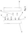
- Figs 4 and 5show a competition format for an assay device in accordance with the invention.
- the sample cellis defined by two electrodes 41, 42.
- Electrode 41has analyte-receptors 43 disposed thereon.
- the redox enzyme 45comprises the enzyme coupled to an analyte or an analyte mimetic. In the absence of analyte, as shown in Fig. 4 , redox enzyme 45 is coupled to analyse receptor 43, resulting in an asymmetry in the distribution of the redox enzyme. Additional redox enzyme 45' may be present in the bulk of the sample depending on the amount of redox enzyme, analyte receptors and the affinity of the analyte receptors for the redox enzyme. As shown in Fig.
- analyte 44when analyte 44 is present, it competes with redox enzyme 45 for the analyte receptor 43, resulting in the displacement of at least some of the redox enzyme 45 from the analyte receptors 43, creating a less asymmetric distribution of the redox enzyme and thus the ability to determine analyte in a sample.
- Figs. 6A-Cshow a sample cell for a device in accordance with the invention, constructed using facing electrodes.
- the deviceis formed from a top layer 61 and bottom layer 62 , each having a conductive surface (61', 62') facing the interior of the device, and an insulating spacer layer 63.
- Contacts 64 and 65extend from the top layer 61 and bottom layer 62 to allow contact with the conductive surfaces for either potentiometric or amperometric measurements.
- the conductive layer 63has an opening therein that together with the facing conductive surfaces 61' and 62' defines a sample cell. This sample cell is open to the exterior for introduction of sample, for example through an opening 66 at the end device as shown in Fig.
- one of the conductive surfaces(61' or 62') has the analyte receptor (immobilized test reagent) disposed thereon.
- the remainder of the reagents for determination of analytemay be disposed within the sample cell as a dried reagent layer 67, or may be added to the sample prior to introduction to the sample cell.
- the sample cell portion as shown in Figs 6A-Cis generally constructed as a single use, disposable component.
- the first and electrodesmay be disposed on the same surface within the sample cell.
- This configurationis referred to herein as side-by-side electrodes.
- Figs. 7A-Cshow non-limiting examples of configurations that can be used for side-by-side configurations, including parallel strips ( Fig. 7A ), interdigitated strips (7B) and concentric rings ( Fig. 7C ).
- asymmetry in redox enzyme distribution between one electrode 71 and the other electrode 72results in a measurable chemical potential gradient between the two electrodes.
- sample cell portions as shown in Figs 7A-Care generally constructed as a single use, disposable component.
- the device of the inventionhas a means for communicating the observed potential or current to a user in a meaningful way indicative of the determination of analyte. This can range from a simple qualitative result (analyte present or not present), or to a specific numerical value for the amount of analyte. The sophistication of the communication means varies accordingly.
- the devicemay have at a visible location a spot of a material that changes color in response to the passage of current or the application of the potential difference created by an asymmetry above a threshold level.
- the devicedoes not need a separate meter portion, and may be simply a disposable test strip with an indicator spot on the outside.
- the sample cellwill be contained within a disposable test strip that is inserted into a reusable meter.
- the meterwill contain the electronics for measuring the potential difference or current at a defined period of time after introduction of a sample or test strip, and for conversion of the measured value to a displayed value. This conversion may make use of a look-up table that converts specific value of current or potential to values of analyte depending on the calibration values for the specific device geometry and analyte.
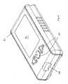
- Fig. 8shows an external view of a meter in accordance with the invention.
- the meterhas a housing 81 having a display 82 and one or more control interfaces 83 (for example power buttons, or scroll wheels etc).
- the housinghas a slot 84 for receiving a test device.
- circuitryInternal to the housing 81 is circuitry for applying a potential or current to the electrodes of the test device when a sample is applied. This may be done following an initialization signal from a user, or following an automated detection of test device insertion and sample application.
- Suitable circuits usable in the meter of the inventionare known in the art, for example from US Patent Publication No. US 2005-0265094 A1 .
- One such circuitis shown in Fig. 9 .
- an ideal voltmeter 942is provided which can measure the potential across the electrodes 941, 938.
- Switch 944is provided which is opened when the potential is to be measured or closed for measurement of current.
- the cell 939is "floating" as to at least one of its electrodes, permitting a voltage measurement that is unaffected by signals at the amplifier 935.
- the switch 944may be a mechanical switch (e.g. a relay) or an FET (field-effect transistor) switch, or a solid-state switch. In a simple case the switch opens to an open circuit; more generally it could open to a very high resistance.
- This circuitcan be used to measure either a potential difference or a current difference.
- other circuitsincluding much simpler and more complicated circuits can be used to achieve application of either or both of a potential difference or a current.
- the circuit of Fig. 9can also be used to apply a potential difference to the test device of the invention. While, as discussed above, such application of potential is not required to perform the measurement of the invention, application of potential prior to the measurement (particularly in a test device with facing electrode construction) can result in a more rapid measurement time by effectively driving analyte and/or analyte-binding enzyme component towards the electrode with the immobilized reagent using what is in essence electrophoresis, provided that the analyte or analyte-binding enzyme component is charged under the conditions (particularly pH) found within the test device. A step function or a sine wave passing from negative to positive potential differences could also effect something similar to washing in situ within the test device.
- the present inventionprovides the ability to perform binding assays for the detection of analyte with electrochemical detection, without the need to apply an external potential or current, and without the need for washing steps commonly employed in sandwich immunoassay procedures. Because of this, the apparatus used to perform the assay can be much simpler, easy to use, and less expensive. In addition, the device components in an electrochemical assay are more robust than those used for example in optical measurements, facilitating the manufacture of the low cost reusable meter for use with disposable test devices.
- the present inventioncan make use of small samples of blood, tears, saliva, or sweat, with minimal invasiveness to the subject. (samples of less than 10 ul, preferably less than 1 ul are particularly desirable for blood tests). Further, the present invention can provide for very rapid test times. Common immunoassay procedures take up to an hour or more.
- the small volume of the test devices of the invention and the sensitivity of the test to small differences in the distribution of the enzymemeans that shorter times (for example less the 30 minutes, more preferably less than 10 minutes, and most preferably less than 1 minute) are accessible depending on the concentration of analyte to be measured and the binding kinetics of the analyte with the binding elements of the mobile and immobilized reagents.
- endogenous glucosecan be used as a component of the redox substrate in a glucose oxidase-based system when the sample is a blood sample.
- An electrochemical cell test stripcomprising two gold electrodes separated by a double-sided adhesive layer was constructed using the method described in US Patent Publication No. US-2005-0258035-A1 .
- An total of 100 nL enzyme solution(27 mg/mL glucose oxidase in 100 mM sodium citrate buffer pH 4.1) was dispensed onto the two electrodes and allowed to dry.
- Test stripswere made with different ratios of electrode enzyme activity by apportioning the 100 nL enzyme solution between the two electrodes, with the balance made up with water.
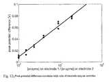
- Fig. 12shows that peak potential difference attained correlated with the ratio of enzyme activity dispensed on each electrode.
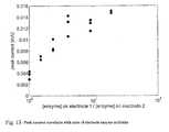
- Fig. 13shows that peak current attained correlated with the ratio of enzyme activity dispensed on each electrode.
- the amount of enzyme (E1) present at one electrodecan be determined independent of the amount (E2) present at the other electrode.
- Test strips containing a range of 0.25 microgram to 1 microgram of glucose oxidasewere made, with the enzyme distributed between the two electrodes such that R was between 1.5 and 19. These strips were made by dispensing a solution of 0.25 microgram to 1 microgram glucose oxidase in 100 nL of 100 mM sodium citrate buffer pH 4.1 onto electrode 1, and a solution of 0 to 0.4 microgram glucose oxidase in 100 nL of 100 mM sodium citrate buffer pH 4.1 onto electrode 2, then allowing the dispensed solutions to dry.
- Fig. 14shows a schematic of known total enzyme E t on the x-axis and measured I 300 on the y-axis.
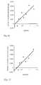
- the parameters a and bcan be calculated from the plots in Fig. 16 and the parameters c and d from Fig. 17 . Once the parameters a, b, c, d, m and n have been determined. E1 can be calculated as follows:
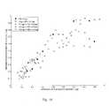
- Fig. 18shows calculated values of E 1 versus actual values of E 1 , for strips with varying amounts of enzyme on the two electrodes.
- Fig. 18indicates that our estimated values for the enzyme dispensed on one electrode correlated well with the actual amount that was dispensed, and were independent of the amount of enzyme dispensed on the other electrode.
Landscapes
- Health & Medical Sciences (AREA)
- Life Sciences & Earth Sciences (AREA)
- Chemical & Material Sciences (AREA)
- Immunology (AREA)
- Engineering & Computer Science (AREA)
- Molecular Biology (AREA)
- Organic Chemistry (AREA)
- Urology & Nephrology (AREA)
- Hematology (AREA)
- Analytical Chemistry (AREA)
- Physics & Mathematics (AREA)
- Biochemistry (AREA)
- Biomedical Technology (AREA)
- General Health & Medical Sciences (AREA)
- Biotechnology (AREA)
- Microbiology (AREA)
- Wood Science & Technology (AREA)
- Zoology (AREA)
- Proteomics, Peptides & Aminoacids (AREA)
- General Physics & Mathematics (AREA)
- Pathology (AREA)
- Food Science & Technology (AREA)
- Medicinal Chemistry (AREA)
- Cell Biology (AREA)
- General Engineering & Computer Science (AREA)
- Genetics & Genomics (AREA)
- Bioinformatics & Cheminformatics (AREA)
- Biophysics (AREA)
- Chemical Kinetics & Catalysis (AREA)
- Electrochemistry (AREA)
- Tropical Medicine & Parasitology (AREA)
- Toxicology (AREA)
- Apparatus Associated With Microorganisms And Enzymes (AREA)
- Measuring Or Testing Involving Enzymes Or Micro-Organisms (AREA)
- Investigating Or Analysing Biological Materials (AREA)
Description
- This application relates to an apparatus and method for electrochemical detection of an analyte in a sample. The invention utilizes a specific binding relationship between the analyte and at least one reagent provided in the apparatus as a means for detecting the analyte.
- Analysis methods in which specific binding between an analyte and a reagent forms the basis for the assay are known. For example, in enzyme-linked immunoassay (EIA or ELISA) procedures, a sandwich is formed between an immobilized antibody and a mobile enzyme-antibody reagent when analyte is present through the interaction of the analyte with the antibody components. This results in the immobilization of the enzyme. The subsequent detection of immobilized enzyme is therefore indicative the presence of analyte in a test solution. (See
US Patents Nos. 3,654,090 ,4,169,012 , and4,642,285 ) Similar sandwich assays are used in chromatographic immunoassays where a colored tag (for example a colored latex bead) on the mobile reagent becomes trapped on a substrate at a defined location to produce a pattern that indicates the presence of analyte in a sample. (SeeUS Patents Nos. 4,943,522 ,5,656,503 ,5,712,172 and5,766,961 ) Analysis methods that depend on specific binding between an analyte and a reagent may also take the form of competition assays, in which the formation of a complex involving a labeled reagent is inhibited in the presence of analyte in an analyte-concentration dependent manner (SeeUS Patents Nos. 4,868,131 ,5,981,298 and5,989,921 ), or displacement assays in which a pre-existing complex involving a labeled reagent is disrupted in the presence of analyte in an analyte-concentration dependent manner. (SeeUS Patents Nos. 4,746,631 and6,020,209 ). - Immunoassays in which detection of the analyte depends on an electrochemical measurement are also known.
US Patent No. 5,149,630 discloses an assay in which the extent to which the transfer of electrons between an enzyme substrate and an electrode, associated with the substrate reaction, is perturbed by complex formation or by displacement of any ligand complex relative to unbound enzyme-labelled component. This determination is made in the presence of an applied potential. An applied potential is also used to measure current in the assay device disclosed inUS Patents Nos. 5,198,367 ,5,427,912 .US Patent No. 5,494,831 discloses the application of a current and the measurement of changes in impedance that result in binding. - According to one aspect of the present invention there is provided an apparatus for determining an analyte in a sample comprising
- (a) a test strip comprising
- (i) first and second electrodes disposed to contact a test cell for receiving sample, wherein an immobilizable test reagent comprising an analyte binding portion is disposed in the test cell, said immobilizable test reagent being immobilizable on the first electrode via a non-analyte specific linking agent, wherein said immobilizable test reagent is immobilized before or after addition of sample to the test strip; and
- (ii) a mobile test reagent comprising a redox enzyme portion and an analyte binding portion, such that the mobile test reagent has a first distribution relative to the electrodes when analyte is present in the sample and a second distribution relative to the electrodes when analyte is not present in the sample, one of said first and second distributions being asymmetric between the electrode, and the other of the first and second distributions being symmetric or less symmetric between the electrodes; and
- (b) a circuit for detecting the symmetric, less asymmetric, or asymmetric distribution of the mobile test reagent in the test cell in the absence of an applied external potential or current; and
- (c) means for communicating the detected distribution to a user.
- In a further aspect, the present invention provides a method for determining an analyte in a sample, comprising the steps of:
- (a) introducing the sample to a test cell comprising
- (i) first and second electrodes, wherein an immobilizable test reagent comprising an analyte binding portion is disposed in the test cell, said immobilizable test reagent being immobilizable on the first electrode via a non-analyte specific linking agent, wherein said immobilizable test reagent is immobilized before or after addition of sample to the test cell; and
- (ii) a mobile test reagent comprising a redox enzyme portion and an analyte binding portion;
- (b) supplying a redox substrate for the redox enzyme in the test cell, said redox substrate being acted upon by the redox enzyme to produce a chemical potential gradient between the first and second electrodes, wherein the magnitude of the chemical potential gradient is determined by the distribution of the mobile test reagent and thus on the presence of analyte, and
- (c) detecting the chemical potential gradient between the first and second electrodes by observing the potential difference between the electrodes or by observing the current flow between the electrodes to determine analyte in the sample, wherein the formation and detection of the chemical potential gradient are performed without the need to apply an external potential or current.
- The present invention provides a new method and apparatus for electrochemical detection of analyte in a sample that makes use of a binding interaction. The invention relies on the discovery that asymmetric distribution of a redox enzyme between two electrodes that occurs when a redox enzyme-containing reagent is immobilized at the surface of one electrode can be detected as a chemical potential gradient arising from an asymmetry in the distribution of oxidized or reduced redox substrate. This chemical potential gradient can be detected potentiometrically by observing the potential difference between the electrodes in an open circuit, or amperometrically by observing the current flow between the electrodes when the circuit is closed. In both cases, the observation of asymmetry can be done without the application of an external potential or current to the electrodes.
- In a first embodiment of the present disclosure, a sandwich type assay is utilized. In this embodiment, a sample to be tested for analyte is introduced to a test cell in the presence of a mobile test reagent. The test cell comprises a first and a second electrode. The first electrode has immobilized on the surface thereof an immobilized test reagent. The mobile test reagent comprises an analyte-binding portion and a redox enzyme portion, and the immobilized test reagent comprises an analyte binding portion. If analyte is present in the sample in the test cell, at least a portion of the mobile test reagent becomes immobilized on the first electrode thereby creating an asymmetry in redox enzyme concentration between the first and second electrodes when analyte is present. A redox substrate for the redox enzyme in the test cell is also supplied. The redox substrate is acted upon (oxidized or reduced) by the redox enzyme. If there is an asymmetry in redox enzyme concentration between the first and second electrodes (i.e. when analyte is present in the sample), this results in a chemical potential gradient between the first and second electrodes. This chemical potential gradient is detected to determine analyte in the sample. In this embodiment, the greater the asymmetry and the resulting potential gradient, the greater the amount of analyte in the sample.
- In a second embodiment of the present disclosure, a competition or displacement type of assay is utilized. In this assay, the redox enzyme is coupled to analyte or an analog of the analyte that can bind to a common immobilized test reagent. Optionally, the redox enzyme is provided already bound to the electrode via the immobilized test reagent. When sample is added, analyte present in the sample will compete with the redox enzyme for the binding sites provided by the immobilized test reagent resulting in a reduction in the amount of asymmetry that would occur is all of the binding sites were occupied by redox enzyme.
- Figs. IA and B show schematic representations of reduced mediator distribution between two electrodes when redox enzyme distribution is asymmetric (
Fig. 1 A) or symmetric (Fig. 1B ).Figs. 2A and B illustrate the determination of asymmetric enzyme distribution at two electrodes using amperometry. Fig. 3 shows a sandwich assay format useful in the present invention.Figs. 4 and5 shows competitionidisplacement assay format useful in the present invention.Figs. 6A-C shows construction of a test cell with facing electrodes.Figs. 7A-C show examples of side-by-side electrode configurations.Fig. 8 shows an external view of a meter in accordance with the invention.Fig. 9 shows a circuit usable in the meter of the invention.Fig. 10 shows potential difference in open circuit as a function of time for different levels of asymmetry in enzyme distribution between two electrodes.Fig. 11 shows current in short circuit as a function of time for different levels of asymmetry in enzyme distribution between two electrodes.Fig. 12 shows the correlation of peak potential difference with ratio of electrode enzyme activitiesFig. 13 shows the correlation of peak current with ratio of electrode enzyme activitiesFig. 14 shows a schematic plot of a known total enzyme E, on x-axis and measured I300 on the y-axis.Fig. 15 shows a schematic plot of a known E, on x-axis and measured l0 on the y-axis.Fig. 16 shows a plot of how log (R) affects the slope of I0 versus Et which is used to derive paramers a and b.Fig. 17 shows a plot of log (R) affects the intercept of I0 versus Et which is used to derive parameters c and d.Fig. 18 shows the correlation between the actual amount of an enzyme and the estimated amount of enzyme as determined in accordance with the invention.- As used in the specification and claims of this application, the following definitions should be applied:
- (a) "analyte" refers to a material of interest that may be present in a sample. Analytes that are detectable in the present invention are those that can be associated in a specific-binding interaction with at least one other reagent to that they can participate in a sandwich, competition or displacement assay configuration as described herein. Examples of analytes include antigens or haptens such as peptides (for example hormones), proteins (for example, enzymes), drugs, pesticides, microorganisms, antibodies, and nucleic acids that can participate in sequence specific hybridization reactions with a complementary sequence,.
- (b) "analyte-specific enzyme component" or reagent refers to a reagent that includes both an analyte-binding portion and a redox enzyme portion. An analyte-specific enzyme component is suitably used as a mobile reagent.
- (c) "determination of an analyte" refers to qualitative, semi-quantitative and quantitative processes for evaluating a sample. In a qualitative evaluation, a result indicates whether or not analyte was detected in the sample. In a semi-quantitative revaluation, the result indicates whether or not analyte is present above some pre-defined threshold. In a quantitative evaluation, the result is a numerical indication of the amount of analyte present.
- (d) the term "redox enzyme" refers to an enzyme that oxidizes or reduces a substrate. Such enzymes may generally be known as oxidases, peroxidases, reductases, or dehydrogenases. Enzymes such as glucose oxidase, and various peroxidases are commonly used in the analytical devices, and therefore the preparation of these enzymes in stable form is well known.
- (e) the term "redox substrate" refers to a compound or combination of compounds that interact with the redox enzyme to produce a chemical potential gradient. In some cases, the enzyme substrate may directly produce a redox active species sufficient to create the chemical potential gradient. In others, a secondary compound may be needed. For example, in the case of glucose oxidase, the interaction with glucose to produce gluconolactone and reduced enzyme produces the chemical potential gradient when the reduced enzyme is oxidized by a mediator compound, which is the actual redox active species in the chemical potential gradient. Thus, in this case the "redox substrate" is the combination of the substrate compound glucose and the mediator compound.
- (f) the term "chemical potential gradient" refers to a concentration gradient of a redox active species. It will be appreciated that more rigorously, the potential gradient arises from a gradient in the ratio of reduced to oxidized species between the electrodes, however, the idea of a concentration gradient of one species is more easily visualized and is therefore used here. When such a gradient is present between two electrodes, a potential difference is detectable if the circuit is opened, and a current will flow until the gradient dissipates when the circuit is closed. It will be appreciated that the chemical potential gradient is transient in the devices of the invention, and that the distribution of the redox active species will even out over time, when new redox active species stops being created. The term "chemical potential gradient" as used herein refers only to this transient gradient that arises from the asymmetry of the distribution of redox enzyme and not to any potential gradient that arises from the application of a potential difference or current flow between the electrodes.
- (g) the phrase "detecting the chemical potential gradient between the first and second electrodes" refers to the detection of the chemical potential gradient in either an open or a closed circuit, using either potentiometric or amperometric measurements.
- (h) the terms "enzyme activity" and "enzyme concentration" are used as equivalent terms herein, although it will be appreciated that in ordinary usage they may have different meanings. Activity of an enzyme provides a quantitative measure of the catalytic capability of an enzyme. This depends not only on the physical amount of the enzyme present in the volume (i.e. the concentration), but also on the conditions which affect the catalytic efficiency of the enzyme. The present invention actually measures asymmetry in enzyme activity, since the presence of inactive enzyme will not produce an asymmetry in redox substrate. However, since it is desirable to control the quality of the enzyme and the conditions, this is in effect also a measurement of asymmetry in enzyme concentration.
- (i) the term "immobilized on the first electrode" refers to immobilization directly or indirectly on the surface of the electrode, provided that the material immobilized becomes immobilized in volume associated with the first electrode and closer to the first electrode than the second electrode. For example, in the case of the formation of an electrode-antibody-analyte-antibody-enzyme sandwich, the enzyme is considered to be "immobilized on" the electrode even though there are several intervening moieties in the sandwich.
- (j) the term "immobilized test reagent" refers to the component of a sandwich or competition/displacement reaction that is associated with an electrode when performing the assay of the invention. Immobilization may be through the formation of a chemical bond (covalent or non-covalent) between the immobilized test reagent and the surface of the electrode, or it may be a physical association as through the placement of the immobilized test reagent within a gel or membrane disposed on the surface of the electrode. The immobilized test reagent comprises a binding moiety which interacts with analyte to produce a change in the distribution of the redox enzyme (as part of the analyte-binding enzyme component) when analyte is present in a sample. In some embodiments, the immobilized reagent will be immobilized during initial manufacture of the test apparatus. In other embodiments, immobilization will occur in situ after addition of the sample. Thus, the term immobilized test reagent refers to any circumstance in which the structure:
- electrode-(link)n-reagent with binding site for analyte
- For convenience, the theoretical basis for the invention will be discussed in the context of glucose oxidase as the redox enzyme and a combination of glucose and a mediator as the redox substrate. Nothing in this discussion should be taken as an indication, however, that the invention is limited to use with these materials.
- In common glucose measurement systems, enzyme present in the sample cell oxidizes glucose to gluconolactone, and the enzyme is reduced. Oxidized mediator (for example ferricyanide) reacts with the reduced enzyme to regenerate the oxidized form of the enzyme, and produce reduced mediator. This process continues until either glucose or oxidized mediator is exhausted. If the enzyme is distributed asymmetrically within the sample cell, then the production of reduced mediator is also asymmetric, and the resulting asymmetry in the distribution of reduced mediator persists for a period of time (determined by diffusion parameters) even after exhaustion of the limiting reagent.
- When reduced mediator is present in a solution between two electrodes, the potential difference between the two electrodes is given by the Nernst equation

where E is the potential difference betweenelectrodes 
Figs. 1A and B show schematic representations of reduced mediator distribution between two electrodes (1, 2) when redox enzyme distribution is symmetric (Fig. 1 A) or asymmetric (Fig. 1B ). The equations above can be used to quantitate the ratio of concentrations of enzyme at twoelectrodes enzyme 3 is more active or concentrated at one electrode than the other (i.e., it has an asymmetric distribution as shown inFig. 1A ), the concentration of reduced mediator will be higher at that electrode than the other, giving rise to a electrical potential difference between the electrodes. If equal activity or concentrations of enzyme are present at both electrodes (i.e., it has a symmetric distribution as shown inFig. 1B ), the concentration of reduced mediator at each electrode will be equal, and the electrodes will be at equal electrical potential and the measured potential difference will be 0.- If, instead of potentiometry, the electrodes are connected in short-circuit, the asymmetric distribution of enzyme activity will result in an asymmetric distribution of reduced mediator, that can be observed by following current when the potential difference between the electrodes is forced to zero by closing the circuit between them. If reduced mediator is generated by enzyme activity and diffuses to an electrode, current will flow and sufficient mediator will be reoxidized, such that the reduced mediator concentration is equal at both electrodes. The current flow will be proportional to the difference in flux of reduced mediator to the two electrodes.
Figs. 2A and B illustrate the use of these principles to quantify the ratio of concentrations of enzyme at two electrodes, using amperometry. The two electrodes are connected in short circuit, and the current flowing between them is measured. As electrical potential difference between the electrodes is constrained to zero, mediator will be reduced or oxidized at the electrodes when necessary to maintain an equal chemical potential at each electrode. As reduced mediator is oxidized at one electrode, current will flow and an equivalent quantity of oxidized mediator will be reduced at the other electrode. If the enzyme activity at each electrode is equal, no electron transfer will be necessary to keep the chemical potentials balanced, so no current will flow. If more enzyme activity is present at one electrode than the other, reduced mediator will be consumed at that electrode and produced at the other electrode to maintain a balanced chemical potential, and current will flow.- The theory of the present invention is applicable to the practical application of determining analytes in a sample. This can be done in various binding format. In general, two analyte-specific chemical components are utilized, and these are selected in to correspond to the analyte to be determined. In general, it is desired to have at least one of the components (generally the analyte-receptor) be highly specific for the analyte while the other component can be less specific in its binding. Various non-limiting combinations are set forth in Table 1.
Analyte Analyte receptor binding component of Analyte-specific enzyme disease-specific antibody, for example an antibody to influenza, disease causing organism disease associated-antigen, such as peptide epitope found on an influenza of interest, aptamers antibody that recognizes human antibodies, aptamers amplified nucleic acid sequence including a suspected target and a known primer nucleic acid complementary to the suspected target nucleic acid sequence complementary to the known primer hormone hormone receptor, apatamer or antibody hormone receptor, apatamer or antibody drug drug receptor, aptamer or antibody hormone receptor, apatamer or antibody pesticides pesticide binding proteins, aptamers, antibodies to pesticides pesticide binding proteins, apatmers antibodies that recognize the antibodies to pesticides - As will be understood in the art, the "antibody" incorporated in the device can be a complete antibody such as an immunoglobulin, or it may be a engineered binding portion of an antibody such as a single-chain antibody (scFv) or Domain Antibodies (dAb) as described at www.domantis.com. Immunoassays for drugs are described in
US Patents Nos. 7,220,842 ,5,677,132 and5,618,926 . Immunoassays for pesticides and pesticide degradation products are described inUS Patent No. 6,635,434 . Drug and hormone receptors may be native hormone receptors, or they may be engineered species with similar binding properties as are known in the art. (SeeUS Patents Nos. 7,214,511 , and6,806,359 , Rasmussen et al, J. Biol. Chem., Vol. 276, Issue 7, 4717-4723, February 16, 2001).US Patent Publication 20050130208 discloses a cocaine-specific aptamer that could be used as a binding portion of an analyte-specific enzyme component or as an immobilized test reagent. Other aptmers are listed on the database of the Ellington research group at http://aptamer.icmb.utexas.edu/. Enzyme-aptamer coupling has been described byMir et al. "Different Strategies To Develop an Electrochemical Thrombin Aptasensor." Electrochemical Communication 8 (2006): 505-511. - The components of the reaction are combined in such a way that they result in a difference in distribution symmetry of the redox enzyme that is dependent on the presence or absence of analyte in a sample. Various device formats can achieve this result.
Fig. 3 shows twoelectrodes Electrode 31 has analyte-specific receptors 33 immobilized on the interior surface thereof.Analyte 34 associates with the analytespecific receptors 33. Also present is an analyte-specific enzyme reagent 35 which associates with analyte in such as way that the activity of the enzyme is maintained in the bound and the unbound state, and aredox substrate 36, 36'. Capture of the analyte-specitic enzyme reagent 35 occurs at the surface ofelectrode 31 whenanalyte 34 is present because of the formation of receptor 33-analyte 34-analyte-specific enzyme species 35 sandwich. The activity of the enzyme results in an increased concentration of one form of the redox substrate (in the case ofFig. 3 , of form 36) nearelectrode 31, and hence a detectable chemical potential gradient whose magnitude is related to the amount of analyte develops. When the analyte is not present, the sandwich does not form and thus no detectable chemical potential gradient is produced.Figs 4 and5 show a competition format for an assay device in accordance with the invention. The sample cell is defined by twoelectrodes Electrode 41 has analyte-receptors 43 disposed thereon. Theredox enzyme 45 comprises the enzyme coupled to an analyte or an analyte mimetic. In the absence of analyte, as shown inFig. 4 ,redox enzyme 45 is coupled to analysereceptor 43, resulting in an asymmetry in the distribution of the redox enzyme. Additional redox enzyme 45' may be present in the bulk of the sample depending on the amount of redox enzyme, analyte receptors and the affinity of the analyte receptors for the redox enzyme. As shown inFig. 5 , whenanalyte 44 is present, it competes withredox enzyme 45 for theanalyte receptor 43, resulting in the displacement of at least some of theredox enzyme 45 from theanalyte receptors 43, creating a less asymmetric distribution of the redox enzyme and thus the ability to determine analyte in a sample.Figs. 6A-C show a sample cell for a device in accordance with the invention, constructed using facing electrodes. The device is formed from atop layer 61 andbottom layer 62 , each having a conductive surface (61', 62') facing the interior of the device, and an insulatingspacer layer 63.Contacts top layer 61 andbottom layer 62 to allow contact with the conductive surfaces for either potentiometric or amperometric measurements. As shown inFig. 6B , theconductive layer 63 has an opening therein that together with the facing conductive surfaces 61' and 62' defines a sample cell. This sample cell is open to the exterior for introduction of sample, for example through anopening 66 at the end device as shown inFig. 6C . Various structures for forming cells of this type, with multiple openings and/or vent holes are known in the art for example as the particular design of the cell is not critical to the practicing of the present invention. Similarly, other designs for connectors are known, and this also is not critical to the practicing of the present invention.- In an embodiment of the device of the invention, one of the conductive surfaces (61' or 62') has the analyte receptor (immobilized test reagent) disposed thereon. The remainder of the reagents for determination of analyte may be disposed within the sample cell as a dried
reagent layer 67, or may be added to the sample prior to introduction to the sample cell. - The sample cell portion as shown in
Figs 6A-C is generally constructed as a single use, disposable component. - In addition to facing electrodes as discussed above, the first and electrodes may be disposed on the same surface within the sample cell. This configuration is referred to herein as side-by-side electrodes.
Figs. 7A-C show non-limiting examples of configurations that can be used for side-by-side configurations, including parallel strips (Fig. 7A ), interdigitated strips (7B) and concentric rings (Fig. 7C ). In each case, asymmetry in redox enzyme distribution between oneelectrode 71 and theother electrode 72 results in a measurable chemical potential gradient between the two electrodes. - The sample cell portions as shown in
Figs 7A-C are generally constructed as a single use, disposable component. - In addition to the sample cell, the device of the invention has a means for communicating the observed potential or current to a user in a meaningful way indicative of the determination of analyte. This can range from a simple qualitative result (analyte present or not present), or to a specific numerical value for the amount of analyte. The sophistication of the communication means varies accordingly.
- In one embodiment of the invention, to provide a qualitative result, the device may have at a visible location a spot of a material that changes color in response to the passage of current or the application of the potential difference created by an asymmetry above a threshold level. In this case, the device does not need a separate meter portion, and may be simply a disposable test strip with an indicator spot on the outside.
- More commonly, the sample cell will be contained within a disposable test strip that is inserted into a reusable meter. The meter will contain the electronics for measuring the potential difference or current at a defined period of time after introduction of a sample or test strip, and for conversion of the measured value to a displayed value. This conversion may make use of a look-up table that converts specific value of current or potential to values of analyte depending on the calibration values for the specific device geometry and analyte.
Fig. 8 shows an external view of a meter in accordance with the invention. As shown, the meter has ahousing 81 having adisplay 82 and one or more control interfaces 83 (for example power buttons, or scroll wheels etc). The housing has aslot 84 for receiving a test device. Internal to thehousing 81 is circuitry for applying a potential or current to the electrodes of the test device when a sample is applied. This may be done following an initialization signal from a user, or following an automated detection of test device insertion and sample application.- Suitable circuits usable in the meter of the invention are known in the art, for example from US Patent Publication No.
US 2005-0265094 A1 . One such circuit is shown inFig. 9 . InFig. 9 , anideal voltmeter 942 is provided which can measure the potential across theelectrodes Switch 944 is provided which is opened when the potential is to be measured or closed for measurement of current. When ope, thecell 939 is "floating" as to at least one of its electrodes, permitting a voltage measurement that is unaffected by signals at theamplifier 935. Theswitch 944 may be a mechanical switch (e.g. a relay) or an FET (field-effect transistor) switch, or a solid-state switch. In a simple case the switch opens to an open circuit; more generally it could open to a very high resistance. - This circuit can be used to measure either a potential difference or a current difference. As will be appreciated by persons skilled in the art, other circuits, including much simpler and more complicated circuits can be used to achieve application of either or both of a potential difference or a current.
- The circuit of
Fig. 9 can also be used to apply a potential difference to the test device of the invention. While, as discussed above, such application of potential is not required to perform the measurement of the invention, application of potential prior to the measurement (particularly in a test device with facing electrode construction) can result in a more rapid measurement time by effectively driving analyte and/or analyte-binding enzyme component towards the electrode with the immobilized reagent using what is in essence electrophoresis, provided that the analyte or analyte-binding enzyme component is charged under the conditions (particularly pH) found within the test device. A step function or a sine wave passing from negative to positive potential differences could also effect something similar to washing in situ within the test device. - The present invention provides the ability to perform binding assays for the detection of analyte with electrochemical detection, without the need to apply an external potential or current, and without the need for washing steps commonly employed in sandwich immunoassay procedures. Because of this, the apparatus used to perform the assay can be much simpler, easy to use, and less expensive. In addition, the device components in an electrochemical assay are more robust than those used for example in optical measurements, facilitating the manufacture of the low cost reusable meter for use with disposable test devices.
- The present invention can make use of small samples of blood, tears, saliva, or sweat, with minimal invasiveness to the subject. (samples of less than 10 ul, preferably less than 1 ul are particularly desirable for blood tests). Further, the present invention can provide for very rapid test times. Common immunoassay procedures take up to an hour or more. The small volume of the test devices of the invention and the sensitivity of the test to small differences in the distribution of the enzyme means that shorter times (for example less the 30 minutes, more preferably less than 10 minutes, and most preferably less than 1 minute) are accessible depending on the concentration of analyte to be measured and the binding kinetics of the analyte with the binding elements of the mobile and immobilized reagents.
- Depending on the nature of the sample and the redox substrate, it may be possible to use materials from the sample as part of the reaction system. For example, endogenous glucose can be used as a component of the redox substrate in a glucose oxidase-based system when the sample is a blood sample.
- In the following examples, the utility and operability of the invention are demonstrated using a model system in which enzyme is coated onto the surface of one of two electrodes in an electrode pair. This model does not require the capture of the enzyme, and therefore is useful for modeling the after-capture behavior with a limited number of variables, although it does not provide a full picture of the binding kinetics of an actual test system. Capture of enzyme using reagents in other enzyme sandwich, competition and displacement assays and the like is well known.
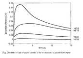
- An electrochemical cell test strip comprising two gold electrodes separated by a double-sided adhesive layer was constructed using the method described in US Patent Publication No.
US-2005-0258035-A1 . An total of 100 nL enzyme solution (27 mg/mL glucose oxidase in 100 mM sodium citrate buffer pH 4.1) was dispensed onto the two electrodes and allowed to dry. Test strips were made with different ratios of electrode enzyme activity by apportioning the 100 nL enzyme solution between the two electrodes, with the balance made up with water. For example to make strips with 75% enzyme activity onelectrode 1 and 25% enzyme activity onelectrode electrode electrode 2. A solution of 100 mM -beta-D-glucose and 100 mM potassium ferricyanide in water was added to the electrochemical cell. The potential difference in open circuit (Fig. 10 ), or current in short circuit (Fig.11 ), was recorded. It is noted that the period of time required to achieve clear differences in the signal at the different levels of asymmetry is short (less than 15 seconds) thus making the invention suitable for rapid measurement. Fig. 12 shows that peak potential difference attained correlated with the ratio of enzyme activity dispensed on each electrode.Fig. 13 shows that peak current attained correlated with the ratio of enzyme activity dispensed on each electrode.- By combining the detennination of the ratio of enzyme activity dispensed on each electrode (as in Example 1) with a determination of total enzyme activity, the amount of enzyme (E1) present at one electrode can be determined independent of the amount (E2) present at the other electrode.
- Varying amounts of enzyme were dispensed on 2 surfaces that served as electrodes in a sandwich configuration as described in Example 1. Ratio of enzyme activity present at the two electrodes (R=E1/E2) was determined by measurement of the current flowing in a short circuit configuration. Then the total enzyme activity (Et=E1+E2) was determined by measuring the current flowing with an applied potential difference. E1 and E2 were then calculated from the determined values of R and Et.
- Test strips containing a range of 0.25 microgram to 1 microgram of glucose oxidase were made, with the enzyme distributed between the two electrodes such that R was between 1.5 and 19. These strips were made by dispensing a solution of 0.25 microgram to 1 microgram glucose oxidase in 100 nL of 100 mM sodium citrate buffer pH 4.1 onto
electrode 1, and a solution of 0 to 0.4 microgram glucose oxidase in 100 nL of 100 mM sodium citrate buffer pH 4.1 ontoelectrode 2, then allowing the dispensed solutions to dry. - A solution of 100 mM beta-D-glucose and 100 mM potassium ferricyanide in water was added to the electrochemical cell and current in short circuit was recorded for 5 seconds. Follcowing this, 300mV was applied for 10s. The current immediately prior to 5s was averaged to give I0 and the current immediately prior to 15s was averaged to give I300 (i.e. the measured I at 5s is I0 and measured I at 15s was designated as I300).
- Measured I (both I0 and I300) for increasing amounts of Et each with a variable ratio R, was recorded and plotted.
Fig. 14 shows a schematic of known total enzyme Et on the x-axis and measured I300 on the y-axis. The relationship between Et and I300 can be established from this plot, for example the data can be represented by the equation
where m and n are the slope and intercept of the line.Fig. 15 shows a schematic plot of a known Et on x-axis and measured I0 on the y-axis. As shown, a family of lines is generated, one for each value of the ratio R. FromFig. 15 , the linear relationship of the I0 current vs Et is dependent on R, ie
- To further establish this function, we plotted known log (R) vs slope (
Fig. 16 ) for each line shown inFig. 15 . In addition, as shown inFig. 17 we plotted known log (R) and intercept for each line inFig. 15 .
Thus the function f can further be defined as the relationship
- The parameters a and b can be calculated from the plots in
Fig. 16 and the parameters c and d fromFig. 17 . Once the parameters a, b, c, d, m and n have been determined. E1 can be calculated as follows: - 1. Calculate Et from I300

- 2. Calculate R from I0 and Et


- 3. Calculate E1 from Et and R

Fig. 18 shows calculated values of E1 versus actual values of E1, for strips with varying amounts of enzyme on the two electrodes.Fig. 18 indicates that our estimated values for the enzyme dispensed on one electrode correlated well with the actual amount that was dispensed, and were independent of the amount of enzyme dispensed on the other electrode.


Claims (10)
- An apparatus for determining an analyte in a sample comprising(a) a test strip comprising(i) first and second electrodes disposed to contact a test cell for receiving sample, wherein an immobilizable test reagent comprising an analyte binding portion is disposed in the test cell, said immobilizable test reagent being immobilizable on the first electrode via a non-analyte specific linking agent, wherein said immobilizable test reagent is immobilized before or after addition of sample to the test strip; and(ii) a mobile test reagent comprising a redox enzyme portion and an analyte binding portion, such that the mobile test reagent has a first distribution relative to the electrodes when analyte is present in the sample and a second distribution relative to the electrodes when analyte is not present in the sample, one of said first and second distributions being asymmetric between the electrode, and the other of the first and second distributions being symmetric or less symmetric between the electrodes; and(b) a circuit for detecting the symmetric, less asymmetric, or asymmetric distribution of the mobile test reagent in the test cell in the absence of an applied external potential or current; and(c) means for communicating the detected distribution to a user.
- The apparatus of claim 1, wherein the immobilizable test reagent is immobilized on the surface of the first electrode during initial manufacture of the test strip.
- The apparatus of claim 1, wherein the immobilizable test reagent is immobilized on the surface of the first electrodein situ after addition of sample.
- The apparatus of any of claims 1 to 3, wherein the circuit detects the potential difference between the first electrode and the second electrode.
- The apparatus of any of claims 1 to 3, wherein the circuit detects current flow in a circuit comprising the electrodes.
- The apparatus of any of claims 1 to 5, wherein the first electrode and the second electrode are in a facing configuration.
- The apparatus of any of claims 1 to 5, wherein the first electrode and the second electrode are in a side-by-side configuration.
- A method for determining an analyte in a sample, comprising the steps of:(a) introducing the sample to a test cell comprising(i) first and second electrodes, wherein an immobilizable test reagent comprising an analyte binding portion is disposed in the test cell, said immobilizable test reagent being immobilizable on the first electrode via a non-analyte specific linking agent, wherein said immobilizable test reagent is immobilized before or after addition of sample to the test cell; and(ii) a mobile test reagent comprising a redox enzyme portion and an analyte binding portion;
such that the mobile test reagent has a first distribution relative to the electrodes when analyte is present in the sample and a second distribution relative to the electrodes when analyte is not present in the sample, one of said first and second distributions being asymmetric between the electrodes, and the other of the first and second distributions being symmetric or less asymmetric between the electrode;(b) supplying a redox substrate for the redox enzyme in the test cell, said redox substrate being acted upon by the redox enzyme to produce a chemical potential gradient between the first and second electrodes, wherein the magnitude of the chemical potential gradient is determined by the distribution of the mobile test reagent and thus on the presence of analyte, and(c) detecting the chemical potential gradient between the first and second electrodes by observing the potential difference between the electrodes or by observing the current flow between the electrodes to determine analyte in the sample, wherein the formation and detection of the chemical potential gradient are performed without the need to apply an external potential or current. - The method of claim 8, wherein
if analyte is present in the sample in the test cell, at least a portion of the mobile test reagent becomes immobilized on the first electrode thereby creating an asymmetric distribution of redox enzyme concentration between the first and second electrodes, and wherein the greater the amount of analyte in the sample, the greater the asymmetry and the greater the resulting potential. - The method of claim 8, wherein
the redox enzyme is coupled to analyte or an analog of the analyte, both the analyte and the analog of the analyte being able to bind to the immobilized test reagent, and wherein if a sample is added to the test cell any analyte present in the sample will compete with the redox enzyme for binding sites provided by the immobilized test reagent resulting in the displacement of at least some of the redox enzyme thereby reducing the asymmetry in the redox enzyme concentration, and
wherein the greater the amount of analyte in the sample the lower the asymmetry and the lower the resulting potential gradient.
Applications Claiming Priority (2)
| Application Number | Priority Date | Filing Date | Title |
|---|---|---|---|
| US95209907P | 2007-07-26 | 2007-07-26 | |
| EP08782340AEP2174135B1 (en) | 2007-07-26 | 2008-07-24 | Electrochemical analyte detection apparatus and method |
Related Parent Applications (2)
| Application Number | Title | Priority Date | Filing Date |
|---|---|---|---|
| EP08782340ADivisionEP2174135B1 (en) | 2007-07-26 | 2008-07-24 | Electrochemical analyte detection apparatus and method |
| EP08782340.7Division | 2008-07-24 |
Publications (3)
| Publication Number | Publication Date |
|---|---|
| EP2584044A2 EP2584044A2 (en) | 2013-04-24 |
| EP2584044A3 EP2584044A3 (en) | 2013-11-27 |
| EP2584044B1true EP2584044B1 (en) | 2015-04-22 |
Family
ID=40281828
Family Applications (2)
| Application Number | Title | Priority Date | Filing Date |
|---|---|---|---|
| EP12199820.7AActiveEP2584044B1 (en) | 2007-07-26 | 2008-07-24 | Electrochemical analyte detections apparatus and method |
| EP08782340AActiveEP2174135B1 (en) | 2007-07-26 | 2008-07-24 | Electrochemical analyte detection apparatus and method |
Family Applications After (1)
| Application Number | Title | Priority Date | Filing Date |
|---|---|---|---|
| EP08782340AActiveEP2174135B1 (en) | 2007-07-26 | 2008-07-24 | Electrochemical analyte detection apparatus and method |
Country Status (7)
| Country | Link |
|---|---|
| US (3) | US20090026075A1 (en) |
| EP (2) | EP2584044B1 (en) |
| KR (1) | KR101532064B1 (en) |
| CN (2) | CN101802612B (en) |
| AU (1) | AU2008279042B2 (en) |
| CA (1) | CA2694045C (en) |
| WO (1) | WO2009015291A1 (en) |
Families Citing this family (52)
| Publication number | Priority date | Publication date | Assignee | Title |
|---|---|---|---|---|
| US6391005B1 (en) | 1998-03-30 | 2002-05-21 | Agilent Technologies, Inc. | Apparatus and method for penetration with shaft having a sensor for sensing penetration depth |
| US8641644B2 (en) | 2000-11-21 | 2014-02-04 | Sanofi-Aventis Deutschland Gmbh | Blood testing apparatus having a rotatable cartridge with multiple lancing elements and testing means |
| US9427532B2 (en) | 2001-06-12 | 2016-08-30 | Sanofi-Aventis Deutschland Gmbh | Tissue penetration device |
| US7981056B2 (en) | 2002-04-19 | 2011-07-19 | Pelikan Technologies, Inc. | Methods and apparatus for lancet actuation |
| US9226699B2 (en) | 2002-04-19 | 2016-01-05 | Sanofi-Aventis Deutschland Gmbh | Body fluid sampling module with a continuous compression tissue interface surface |
| US7344507B2 (en) | 2002-04-19 | 2008-03-18 | Pelikan Technologies, Inc. | Method and apparatus for lancet actuation |
| US8337419B2 (en) | 2002-04-19 | 2012-12-25 | Sanofi-Aventis Deutschland Gmbh | Tissue penetration device |
| US9795747B2 (en) | 2010-06-02 | 2017-10-24 | Sanofi-Aventis Deutschland Gmbh | Methods and apparatus for lancet actuation |
| US7041068B2 (en) | 2001-06-12 | 2006-05-09 | Pelikan Technologies, Inc. | Sampling module device and method |
| EP1395185B1 (en) | 2001-06-12 | 2010-10-27 | Pelikan Technologies Inc. | Electric lancet actuator |
| JP4209767B2 (en) | 2001-06-12 | 2009-01-14 | ペリカン テクノロジーズ インコーポレイテッド | Self-optimized cutting instrument with adaptive means for temporary changes in skin properties |
| US7749174B2 (en) | 2001-06-12 | 2010-07-06 | Pelikan Technologies, Inc. | Method and apparatus for lancet launching device intergrated onto a blood-sampling cartridge |
| US7232451B2 (en) | 2002-04-19 | 2007-06-19 | Pelikan Technologies, Inc. | Method and apparatus for penetrating tissue |
| US7976476B2 (en) | 2002-04-19 | 2011-07-12 | Pelikan Technologies, Inc. | Device and method for variable speed lancet |
| US8267870B2 (en) | 2002-04-19 | 2012-09-18 | Sanofi-Aventis Deutschland Gmbh | Method and apparatus for body fluid sampling with hybrid actuation |
| US9795334B2 (en) | 2002-04-19 | 2017-10-24 | Sanofi-Aventis Deutschland Gmbh | Method and apparatus for penetrating tissue |
| US7229458B2 (en) | 2002-04-19 | 2007-06-12 | Pelikan Technologies, Inc. | Method and apparatus for penetrating tissue |
| US8360992B2 (en) | 2002-04-19 | 2013-01-29 | Sanofi-Aventis Deutschland Gmbh | Method and apparatus for penetrating tissue |
| US7491178B2 (en) | 2002-04-19 | 2009-02-17 | Pelikan Technologies, Inc. | Method and apparatus for penetrating tissue |
| US8221334B2 (en) | 2002-04-19 | 2012-07-17 | Sanofi-Aventis Deutschland Gmbh | Method and apparatus for penetrating tissue |
| US7892183B2 (en) | 2002-04-19 | 2011-02-22 | Pelikan Technologies, Inc. | Method and apparatus for body fluid sampling and analyte sensing |
| US7708701B2 (en) | 2002-04-19 | 2010-05-04 | Pelikan Technologies, Inc. | Method and apparatus for a multi-use body fluid sampling device |
| US7909778B2 (en) | 2002-04-19 | 2011-03-22 | Pelikan Technologies, Inc. | Method and apparatus for penetrating tissue |
| US8702624B2 (en) | 2006-09-29 | 2014-04-22 | Sanofi-Aventis Deutschland Gmbh | Analyte measurement device with a single shot actuator |
| US9248267B2 (en) | 2002-04-19 | 2016-02-02 | Sanofi-Aventis Deustchland Gmbh | Tissue penetration device |
| US7674232B2 (en) | 2002-04-19 | 2010-03-09 | Pelikan Technologies, Inc. | Method and apparatus for penetrating tissue |
| US7331931B2 (en) | 2002-04-19 | 2008-02-19 | Pelikan Technologies, Inc. | Method and apparatus for penetrating tissue |
| US7901362B2 (en) | 2002-04-19 | 2011-03-08 | Pelikan Technologies, Inc. | Method and apparatus for penetrating tissue |
| US7297122B2 (en) | 2002-04-19 | 2007-11-20 | Pelikan Technologies, Inc. | Method and apparatus for penetrating tissue |
| US7547287B2 (en) | 2002-04-19 | 2009-06-16 | Pelikan Technologies, Inc. | Method and apparatus for penetrating tissue |
| US8372016B2 (en) | 2002-04-19 | 2013-02-12 | Sanofi-Aventis Deutschland Gmbh | Method and apparatus for body fluid sampling and analyte sensing |
| US9314194B2 (en) | 2002-04-19 | 2016-04-19 | Sanofi-Aventis Deutschland Gmbh | Tissue penetration device |
| US8579831B2 (en) | 2002-04-19 | 2013-11-12 | Sanofi-Aventis Deutschland Gmbh | Method and apparatus for penetrating tissue |
| US8784335B2 (en) | 2002-04-19 | 2014-07-22 | Sanofi-Aventis Deutschland Gmbh | Body fluid sampling device with a capacitive sensor |
| US8574895B2 (en) | 2002-12-30 | 2013-11-05 | Sanofi-Aventis Deutschland Gmbh | Method and apparatus using optical techniques to measure analyte levels |
| DE602004028463D1 (en) | 2003-05-30 | 2010-09-16 | Pelikan Technologies Inc | METHOD AND DEVICE FOR INJECTING LIQUID |
| US7850621B2 (en) | 2003-06-06 | 2010-12-14 | Pelikan Technologies, Inc. | Method and apparatus for body fluid sampling and analyte sensing |
| WO2006001797A1 (en) | 2004-06-14 | 2006-01-05 | Pelikan Technologies, Inc. | Low pain penetrating |
| US8282576B2 (en) | 2003-09-29 | 2012-10-09 | Sanofi-Aventis Deutschland Gmbh | Method and apparatus for an improved sample capture device |
| EP1680014A4 (en) | 2003-10-14 | 2009-01-21 | Pelikan Technologies Inc | METHOD AND DEVICE FOR A VARIABLE USER INTERFACE |
| US8668656B2 (en) | 2003-12-31 | 2014-03-11 | Sanofi-Aventis Deutschland Gmbh | Method and apparatus for improving fluidic flow and sample capture |
| US7822454B1 (en) | 2005-01-03 | 2010-10-26 | Pelikan Technologies, Inc. | Fluid sampling device with improved analyte detecting member configuration |
| WO2006011062A2 (en) | 2004-05-20 | 2006-02-02 | Albatros Technologies Gmbh & Co. Kg | Printable hydrogel for biosensors |
| WO2005120365A1 (en) | 2004-06-03 | 2005-12-22 | Pelikan Technologies, Inc. | Method and apparatus for a fluid sampling device |
| US9775553B2 (en) | 2004-06-03 | 2017-10-03 | Sanofi-Aventis Deutschland Gmbh | Method and apparatus for a fluid sampling device |
| US8652831B2 (en) | 2004-12-30 | 2014-02-18 | Sanofi-Aventis Deutschland Gmbh | Method and apparatus for analyte measurement test time |
| EP2265324B1 (en) | 2008-04-11 | 2015-01-28 | Sanofi-Aventis Deutschland GmbH | Integrated analyte measurement system |
| US9375169B2 (en) | 2009-01-30 | 2016-06-28 | Sanofi-Aventis Deutschland Gmbh | Cam drive for managing disposable penetrating member actions with a single motor and motor and control system |
| US8965476B2 (en) | 2010-04-16 | 2015-02-24 | Sanofi-Aventis Deutschland Gmbh | Tissue penetration device |
| CN102409359A (en)* | 2011-11-22 | 2012-04-11 | 中国铝业股份有限公司 | Online measuring device and method for alumina concentration in aluminum electrolytic cell |
| EP2657347A1 (en) | 2012-04-26 | 2013-10-30 | Université Paris Diderot - Paris 7 | Electrochemical competitive assay and use thereof |
| CN110609139B (en)* | 2018-06-14 | 2023-06-30 | 深圳市理邦精密仪器股份有限公司 | Antigen concentration excess detection method, device and storage medium |
Family Cites Families (38)
| Publication number | Priority date | Publication date | Assignee | Title |
|---|---|---|---|---|
| US5622871A (en)* | 1987-04-27 | 1997-04-22 | Unilever Patent Holdings B.V. | Capillary immunoassay and device therefor comprising mobilizable particulate labelled reagents |
| US3654090A (en)* | 1968-09-24 | 1972-04-04 | Organon | Method for the determination of antigens and antibodies |
| US5677132A (en)* | 1971-05-20 | 1997-10-14 | Strahilevitz; Meir | Immunological assay reagent package |
| US4642285A (en) | 1975-09-29 | 1987-02-10 | Diamedix Corporation | Sandwich EIA for antigen |
| NL7610608A (en) | 1976-09-24 | 1978-03-29 | Akzo Nv | PROCESS FOR STABILIZING PEROXIDASE-CONTAINING COMPOSITIONS. |
| GB8402058D0 (en)* | 1984-01-26 | 1984-02-29 | Serono Diagnostics Ltd | Methods of assay |
| US4746631A (en)* | 1985-05-09 | 1988-05-24 | Ultra Diagnostics Corporation | Immunoassay method, device, and test kit |
| JPS6319559A (en) | 1986-07-11 | 1988-01-27 | Fuji Photo Film Co Ltd | Immune analysis method |
| US6794160B1 (en)* | 1986-10-24 | 2004-09-21 | Salk Inst For Biological Studi | Hormone receptor compositions and methods |
| US4943522A (en)* | 1987-06-01 | 1990-07-24 | Quidel | Lateral flow, non-bibulous membrane assay protocols |
| AU2684488A (en) | 1988-06-27 | 1990-01-04 | Carter-Wallace, Inc. | Test device and method for colored particle immunoassay |
| US6306594B1 (en)* | 1988-11-14 | 2001-10-23 | I-Stat Corporation | Methods for microdispensing patterened layers |
| DE69030829T2 (en)* | 1989-03-10 | 1998-01-15 | Hoffmann La Roche | Drugs for the detection of drugs |
| US5198367A (en)* | 1989-06-09 | 1993-03-30 | Masuo Aizawa | Homogeneous amperometric immunoassay |
| DE4003194A1 (en)* | 1990-02-03 | 1991-08-08 | Boehringer Mannheim Gmbh | METHOD AND SENSOR ELECTRODE SYSTEM FOR THE ELECTROCHEMICAL DETERMINATION OF AN ANALYT, OR AN OXIDOR REDUCTASE, AND USE OF SUITABLE COMPOUNDS THEREFOR |
| WO1992012428A1 (en) | 1991-01-11 | 1992-07-23 | Quidel Corporation | A one-step lateral flow nonbibulous assay |
| US5413690A (en)* | 1993-07-23 | 1995-05-09 | Boehringer Mannheim Corporation | Potentiometric biosensor and the method of its use |
| US5427912A (en)* | 1993-08-27 | 1995-06-27 | Boehringer Mannheim Corporation | Electrochemical enzymatic complementation immunoassay |
| US5494831A (en)* | 1993-08-30 | 1996-02-27 | Hughes Aircraft Company | Electrochemical immunosensor system and methods |
| IL108726A (en)* | 1994-02-22 | 1999-12-31 | Yissum Res Dev Co | Electrobiochemical method and system for the determination of an analyte which is a member of a recognition pair in a liquid medium and electrodes therefor |
| US5712172A (en)* | 1995-05-18 | 1998-01-27 | Wyntek Diagnostics, Inc. | One step immunochromatographic device and method of use |
| US5981298A (en)* | 1995-12-13 | 1999-11-09 | Surmodics, Inc. | Immunoassay device and method |
| US5708247A (en)* | 1996-02-14 | 1998-01-13 | Selfcare, Inc. | Disposable glucose test strips, and methods and compositions for making same |
| US6020209A (en)* | 1997-04-28 | 2000-02-01 | The United States Of America As Represented By The Secretary Of The Navy | Microcapillary-based flow-through immunosensor and displacement immunoassay using the same |
| US6635434B1 (en)* | 1999-09-17 | 2003-10-21 | Exiqon A/S | Immunoassay for pesticides and their degradation products |
| KR100348351B1 (en)* | 2000-05-24 | 2002-08-09 | 주식회사 바이오디지트 | Electrochemical membrane strip biosensor |
| CN1204398C (en)* | 2001-05-15 | 2005-06-01 | 松下电器产业株式会社 | Biosensor and method for measuring the same |
| WO2002103343A1 (en) | 2001-06-14 | 2002-12-27 | Matsushita Electric Industrial Co., Ltd. | Biosensor |
| IL145182A (en)* | 2001-08-29 | 2005-11-20 | Yissum Res Dev Co | Self-powered biosensor |
| EP1466015B1 (en)* | 2001-11-09 | 2008-08-06 | Nanosphere, Inc. | Bioconjugate-nanoparticle probes |
| US20030175828A1 (en) | 2002-03-15 | 2003-09-18 | Lazar James G. | Signal amplification by Hybrid Capture |
| US20030198966A1 (en)* | 2002-04-19 | 2003-10-23 | Stojanovic Milan N. | Displacement assay for detection of small molecules |
| CN1447114A (en)* | 2003-02-14 | 2003-10-08 | 李伟 | Method for testing bioactive substance by using electrochemistry process with oxido-reductase marked and its device |
| ES2709991T3 (en)* | 2003-08-21 | 2019-04-22 | Agamatrix Inc | Method and apparatus for the analysis of electrochemical properties |
| US7220842B2 (en)* | 2004-04-05 | 2007-05-22 | Dade Behring Inc. | Immunoassays for buprenorphine and norbuprenorphine |
| JP5215661B2 (en) | 2004-05-21 | 2013-06-19 | アガマトリックス インコーポレーテッド | Electrochemical cell and method for making an electrochemical cell |
| US7964146B2 (en) | 2004-05-30 | 2011-06-21 | Agamatrix, Inc. | Measuring device and methods for use therewith |
| US20060160100A1 (en)* | 2005-01-19 | 2006-07-20 | Agency For Science, Technology And Research | Enzymatic electrochemical detection assay using protective monolayer and device therefor |
- 2008
- 2008-07-24EPEP12199820.7Apatent/EP2584044B1/enactiveActive
- 2008-07-24CACA2694045Apatent/CA2694045C/enactiveActive
- 2008-07-24CNCN200880108191.6Apatent/CN101802612B/enactiveActive
- 2008-07-24EPEP08782340Apatent/EP2174135B1/enactiveActive
- 2008-07-24CNCN201610575436.2Apatent/CN106442961B/enactiveActive
- 2008-07-24AUAU2008279042Apatent/AU2008279042B2/enactiveActive
- 2008-07-24KRKR1020107004269Apatent/KR101532064B1/enactiveActive
- 2008-07-24WOPCT/US2008/071073patent/WO2009015291A1/enactiveApplication Filing
- 2008-07-24USUS12/179,446patent/US20090026075A1/ennot_activeAbandoned
- 2016
- 2016-02-08USUS15/017,787patent/US9939440B2/enactiveActive
- 2018
- 2018-04-03USUS15/944,148patent/US20180231552A1/ennot_activeAbandoned
Also Published As
| Publication number | Publication date |
|---|---|
| KR20100065298A (en) | 2010-06-16 |
| EP2584044A2 (en) | 2013-04-24 |
| CN101802612B (en) | 2016-08-10 |
| CN106442961A (en) | 2017-02-22 |
| CA2694045C (en) | 2016-06-21 |
| US9939440B2 (en) | 2018-04-10 |
| HK1184196A1 (en) | 2014-01-17 |
| AU2008279042A1 (en) | 2009-01-29 |
| CN106442961B (en) | 2018-08-14 |
| CA2694045A1 (en) | 2009-01-29 |
| CN101802612A (en) | 2010-08-11 |
| EP2174135A1 (en) | 2010-04-14 |
| AU2008279042B2 (en) | 2014-03-13 |
| US20180231552A1 (en) | 2018-08-16 |
| WO2009015291A1 (en) | 2009-01-29 |
| EP2584044A3 (en) | 2013-11-27 |
| KR101532064B1 (en) | 2015-06-26 |
| EP2174135B1 (en) | 2013-01-02 |
| US20090026075A1 (en) | 2009-01-29 |
| US20160231321A1 (en) | 2016-08-11 |
| EP2174135A4 (en) | 2010-08-25 |
Similar Documents
| Publication | Publication Date | Title |
|---|---|---|
| EP2584044B1 (en) | Electrochemical analyte detections apparatus and method | |
| Noiphung et al. | Electrochemical detection of glucose from whole blood using paper-based microfluidic devices | |
| US9863942B2 (en) | Biosensor apparatus and methods of use | |
| US20110008813A1 (en) | Assay device and method | |
| Kergaravat et al. | Electrochemical magneto immunosensor for the detection of anti-TG2 antibody in celiac disease | |
| JP5781603B2 (en) | Electrochemical detection method for binding reaction | |
| CN102116753A (en) | Systems, devices, and methods for measuring whole blood hematocrit based on initial fill velocity | |
| US20150226735A1 (en) | Systems and methods for enzyme detection | |
| WO2013039455A1 (en) | Amperometric sensor | |
| AU2013204779B2 (en) | Electrochemical analyte detection apparatus and method | |
| HK1184196B (en) | Electrochemical analyte detections apparatus and method | |
| KR20220135432A (en) | Sandwich ELISA-Based Electrochemical Biosensor for leptin and leptin detecting method using the same | |
| HK1101765B (en) | Biosensor apparatus and methods of use | |
| HK1151589A (en) | Biosensor apparatus and methods of use |
Legal Events
| Date | Code | Title | Description |
|---|---|---|---|
| PUAI | Public reference made under article 153(3) epc to a published international application that has entered the european phase | Free format text:ORIGINAL CODE: 0009012 | |
| AC | Divisional application: reference to earlier application | Ref document number:2174135 Country of ref document:EP Kind code of ref document:P | |
| AK | Designated contracting states | Kind code of ref document:A2 Designated state(s):AT BE BG CH CY CZ DE DK EE ES FI FR GB GR HR HU IE IS IT LI LT LU LV MC MT NL NO PL PT RO SE SI SK TR | |
| PUAL | Search report despatched | Free format text:ORIGINAL CODE: 0009013 | |
| AK | Designated contracting states | Kind code of ref document:A3 Designated state(s):AT BE BG CH CY CZ DE DK EE ES FI FR GB GR HR HU IE IS IT LI LT LU LV MC MT NL NO PL PT RO SE SI SK TR | |
| RIC1 | Information provided on ipc code assigned before grant | Ipc:G01N 33/543 20060101ALI20131021BHEP Ipc:C12Q 1/00 20060101AFI20131021BHEP | |
| REG | Reference to a national code | Ref country code:HK Ref legal event code:DE Ref document number:1184196 Country of ref document:HK | |
| 17P | Request for examination filed | Effective date:20140520 | |
| RBV | Designated contracting states (corrected) | Designated state(s):AT BE BG CH CY CZ DE DK EE ES FI FR GB GR HR HU IE IS IT LI LT LU LV MC MT NL NO PL PT RO SE SI SK TR | |
| GRAP | Despatch of communication of intention to grant a patent | Free format text:ORIGINAL CODE: EPIDOSNIGR1 | |
| INTG | Intention to grant announced | Effective date:20140917 | |
| GRAS | Grant fee paid | Free format text:ORIGINAL CODE: EPIDOSNIGR3 | |
| GRAP | Despatch of communication of intention to grant a patent | Free format text:ORIGINAL CODE: EPIDOSNIGR1 | |
| GRAA | (expected) grant | Free format text:ORIGINAL CODE: 0009210 | |
| INTG | Intention to grant announced | Effective date:20150309 | |
| AC | Divisional application: reference to earlier application | Ref document number:2174135 Country of ref document:EP Kind code of ref document:P | |
| AK | Designated contracting states | Kind code of ref document:B1 Designated state(s):AT BE BG CH CY CZ DE DK EE ES FI FR GB GR HR HU IE IS IT LI LT LU LV MC MT NL NO PL PT RO SE SI SK TR | |
| REG | Reference to a national code | Ref country code:GB Ref legal event code:FG4D | |
| REG | Reference to a national code | Ref country code:CH Ref legal event code:EP | |
| REG | Reference to a national code | Ref country code:AT Ref legal event code:REF Ref document number:723278 Country of ref document:AT Kind code of ref document:T Effective date:20150515 | |
| REG | Reference to a national code | Ref country code:IE Ref legal event code:FG4D | |
| REG | Reference to a national code | Ref country code:DE Ref legal event code:R096 Ref document number:602008037881 Country of ref document:DE Effective date:20150603 | |
| REG | Reference to a national code | Ref country code:NL Ref legal event code:VDEP Effective date:20150422 | |
| REG | Reference to a national code | Ref country code:AT Ref legal event code:MK05 Ref document number:723278 Country of ref document:AT Kind code of ref document:T Effective date:20150422 | |
| REG | Reference to a national code | Ref country code:LT Ref legal event code:MG4D | |
| PG25 | Lapsed in a contracting state [announced via postgrant information from national office to epo] | Ref country code:NL Free format text:LAPSE BECAUSE OF FAILURE TO SUBMIT A TRANSLATION OF THE DESCRIPTION OR TO PAY THE FEE WITHIN THE PRESCRIBED TIME-LIMIT Effective date:20150422 | |
| PG25 | Lapsed in a contracting state [announced via postgrant information from national office to epo] | Ref country code:NO Free format text:LAPSE BECAUSE OF FAILURE TO SUBMIT A TRANSLATION OF THE DESCRIPTION OR TO PAY THE FEE WITHIN THE PRESCRIBED TIME-LIMIT Effective date:20150722 Ref country code:HR Free format text:LAPSE BECAUSE OF FAILURE TO SUBMIT A TRANSLATION OF THE DESCRIPTION OR TO PAY THE FEE WITHIN THE PRESCRIBED TIME-LIMIT Effective date:20150422 Ref country code:ES Free format text:LAPSE BECAUSE OF FAILURE TO SUBMIT A TRANSLATION OF THE DESCRIPTION OR TO PAY THE FEE WITHIN THE PRESCRIBED TIME-LIMIT Effective date:20150422 Ref country code:FI Free format text:LAPSE BECAUSE OF FAILURE TO SUBMIT A TRANSLATION OF THE DESCRIPTION OR TO PAY THE FEE WITHIN THE PRESCRIBED TIME-LIMIT Effective date:20150422 Ref country code:PT Free format text:LAPSE BECAUSE OF FAILURE TO SUBMIT A TRANSLATION OF THE DESCRIPTION OR TO PAY THE FEE WITHIN THE PRESCRIBED TIME-LIMIT Effective date:20150824 Ref country code:LT Free format text:LAPSE BECAUSE OF FAILURE TO SUBMIT A TRANSLATION OF THE DESCRIPTION OR TO PAY THE FEE WITHIN THE PRESCRIBED TIME-LIMIT Effective date:20150422 | |
| PG25 | Lapsed in a contracting state [announced via postgrant information from national office to epo] | Ref country code:LV Free format text:LAPSE BECAUSE OF FAILURE TO SUBMIT A TRANSLATION OF THE DESCRIPTION OR TO PAY THE FEE WITHIN THE PRESCRIBED TIME-LIMIT Effective date:20150422 Ref country code:GR Free format text:LAPSE BECAUSE OF FAILURE TO SUBMIT A TRANSLATION OF THE DESCRIPTION OR TO PAY THE FEE WITHIN THE PRESCRIBED TIME-LIMIT Effective date:20150723 Ref country code:AT Free format text:LAPSE BECAUSE OF FAILURE TO SUBMIT A TRANSLATION OF THE DESCRIPTION OR TO PAY THE FEE WITHIN THE PRESCRIBED TIME-LIMIT Effective date:20150422 Ref country code:IS Free format text:LAPSE BECAUSE OF FAILURE TO SUBMIT A TRANSLATION OF THE DESCRIPTION OR TO PAY THE FEE WITHIN THE PRESCRIBED TIME-LIMIT Effective date:20150822 | |
| REG | Reference to a national code | Ref country code:HK Ref legal event code:GR Ref document number:1184196 Country of ref document:HK | |
| REG | Reference to a national code | Ref country code:DE Ref legal event code:R097 Ref document number:602008037881 Country of ref document:DE | |
| PG25 | Lapsed in a contracting state [announced via postgrant information from national office to epo] | Ref country code:DK Free format text:LAPSE BECAUSE OF FAILURE TO SUBMIT A TRANSLATION OF THE DESCRIPTION OR TO PAY THE FEE WITHIN THE PRESCRIBED TIME-LIMIT Effective date:20150422 Ref country code:EE Free format text:LAPSE BECAUSE OF FAILURE TO SUBMIT A TRANSLATION OF THE DESCRIPTION OR TO PAY THE FEE WITHIN THE PRESCRIBED TIME-LIMIT Effective date:20150422 | |
| PLBE | No opposition filed within time limit | Free format text:ORIGINAL CODE: 0009261 | |
| STAA | Information on the status of an ep patent application or granted ep patent | Free format text:STATUS: NO OPPOSITION FILED WITHIN TIME LIMIT | |
| PG25 | Lapsed in a contracting state [announced via postgrant information from national office to epo] | Ref country code:PL Free format text:LAPSE BECAUSE OF FAILURE TO SUBMIT A TRANSLATION OF THE DESCRIPTION OR TO PAY THE FEE WITHIN THE PRESCRIBED TIME-LIMIT Effective date:20150422 Ref country code:SK Free format text:LAPSE BECAUSE OF FAILURE TO SUBMIT A TRANSLATION OF THE DESCRIPTION OR TO PAY THE FEE WITHIN THE PRESCRIBED TIME-LIMIT Effective date:20150422 Ref country code:CZ Free format text:LAPSE BECAUSE OF FAILURE TO SUBMIT A TRANSLATION OF THE DESCRIPTION OR TO PAY THE FEE WITHIN THE PRESCRIBED TIME-LIMIT Effective date:20150422 Ref country code:MC Free format text:LAPSE BECAUSE OF FAILURE TO SUBMIT A TRANSLATION OF THE DESCRIPTION OR TO PAY THE FEE WITHIN THE PRESCRIBED TIME-LIMIT Effective date:20150422 Ref country code:RO Free format text:LAPSE BECAUSE OF NON-PAYMENT OF DUE FEES Effective date:20150422 | |
| REG | Reference to a national code | Ref country code:CH Ref legal event code:PL | |
| 26N | No opposition filed | Effective date:20160125 | |
| PG25 | Lapsed in a contracting state [announced via postgrant information from national office to epo] | Ref country code:LU Free format text:LAPSE BECAUSE OF FAILURE TO SUBMIT A TRANSLATION OF THE DESCRIPTION OR TO PAY THE FEE WITHIN THE PRESCRIBED TIME-LIMIT Effective date:20150724 | |
| PG25 | Lapsed in a contracting state [announced via postgrant information from national office to epo] | Ref country code:LI Free format text:LAPSE BECAUSE OF NON-PAYMENT OF DUE FEES Effective date:20150731 Ref country code:IT Free format text:LAPSE BECAUSE OF FAILURE TO SUBMIT A TRANSLATION OF THE DESCRIPTION OR TO PAY THE FEE WITHIN THE PRESCRIBED TIME-LIMIT Effective date:20150422 Ref country code:CH Free format text:LAPSE BECAUSE OF NON-PAYMENT OF DUE FEES Effective date:20150731 | |
| REG | Reference to a national code | Ref country code:FR Ref legal event code:ST Effective date:20160331 | |
| PG25 | Lapsed in a contracting state [announced via postgrant information from national office to epo] | Ref country code:SI Free format text:LAPSE BECAUSE OF FAILURE TO SUBMIT A TRANSLATION OF THE DESCRIPTION OR TO PAY THE FEE WITHIN THE PRESCRIBED TIME-LIMIT Effective date:20150422 Ref country code:FR Free format text:LAPSE BECAUSE OF NON-PAYMENT OF DUE FEES Effective date:20150731 | |
| PG25 | Lapsed in a contracting state [announced via postgrant information from national office to epo] | Ref country code:BE Free format text:LAPSE BECAUSE OF FAILURE TO SUBMIT A TRANSLATION OF THE DESCRIPTION OR TO PAY THE FEE WITHIN THE PRESCRIBED TIME-LIMIT Effective date:20150422 | |
| PG25 | Lapsed in a contracting state [announced via postgrant information from national office to epo] | Ref country code:MT Free format text:LAPSE BECAUSE OF FAILURE TO SUBMIT A TRANSLATION OF THE DESCRIPTION OR TO PAY THE FEE WITHIN THE PRESCRIBED TIME-LIMIT Effective date:20150422 | |
| PG25 | Lapsed in a contracting state [announced via postgrant information from national office to epo] | Ref country code:HU Free format text:LAPSE BECAUSE OF FAILURE TO SUBMIT A TRANSLATION OF THE DESCRIPTION OR TO PAY THE FEE WITHIN THE PRESCRIBED TIME-LIMIT; INVALID AB INITIO Effective date:20080724 Ref country code:BG Free format text:LAPSE BECAUSE OF FAILURE TO SUBMIT A TRANSLATION OF THE DESCRIPTION OR TO PAY THE FEE WITHIN THE PRESCRIBED TIME-LIMIT Effective date:20150422 | |
| PG25 | Lapsed in a contracting state [announced via postgrant information from national office to epo] | Ref country code:CY Free format text:LAPSE BECAUSE OF FAILURE TO SUBMIT A TRANSLATION OF THE DESCRIPTION OR TO PAY THE FEE WITHIN THE PRESCRIBED TIME-LIMIT Effective date:20150422 Ref country code:SE Free format text:LAPSE BECAUSE OF FAILURE TO SUBMIT A TRANSLATION OF THE DESCRIPTION OR TO PAY THE FEE WITHIN THE PRESCRIBED TIME-LIMIT Effective date:20150422 | |
| PG25 | Lapsed in a contracting state [announced via postgrant information from national office to epo] | Ref country code:TR Free format text:LAPSE BECAUSE OF FAILURE TO SUBMIT A TRANSLATION OF THE DESCRIPTION OR TO PAY THE FEE WITHIN THE PRESCRIBED TIME-LIMIT Effective date:20150422 | |
| PGFP | Annual fee paid to national office [announced via postgrant information from national office to epo] | Ref country code:DE Payment date:20240729 Year of fee payment:17 Ref country code:IE Payment date:20240729 Year of fee payment:17 | |
| PGFP | Annual fee paid to national office [announced via postgrant information from national office to epo] | Ref country code:GB Payment date:20240729 Year of fee payment:17 |