EP2582468B1 - Inhaler - Google Patents
InhalerDownload PDFInfo
- Publication number
- EP2582468B1 EP2582468B1EP11723062.3AEP11723062AEP2582468B1EP 2582468 B1EP2582468 B1EP 2582468B1EP 11723062 AEP11723062 AEP 11723062AEP 2582468 B1EP2582468 B1EP 2582468B1
- Authority
- EP
- European Patent Office
- Prior art keywords
- inhaler
- monitoring device
- sensor
- pressure
- container
- Prior art date
- Legal status (The legal status is an assumption and is not a legal conclusion. Google has not performed a legal analysis and makes no representation as to the accuracy of the status listed.)
- Active
Links
Images


Classifications
- A—HUMAN NECESSITIES
- A61—MEDICAL OR VETERINARY SCIENCE; HYGIENE
- A61M—DEVICES FOR INTRODUCING MEDIA INTO, OR ONTO, THE BODY; DEVICES FOR TRANSDUCING BODY MEDIA OR FOR TAKING MEDIA FROM THE BODY; DEVICES FOR PRODUCING OR ENDING SLEEP OR STUPOR
- A61M15/00—Inhalators
- A61M15/0091—Inhalators mechanically breath-triggered
- A—HUMAN NECESSITIES
- A61—MEDICAL OR VETERINARY SCIENCE; HYGIENE
- A61M—DEVICES FOR INTRODUCING MEDIA INTO, OR ONTO, THE BODY; DEVICES FOR TRANSDUCING BODY MEDIA OR FOR TAKING MEDIA FROM THE BODY; DEVICES FOR PRODUCING OR ENDING SLEEP OR STUPOR
- A61M11/00—Sprayers or atomisers specially adapted for therapeutic purposes
- A61M11/006—Sprayers or atomisers specially adapted for therapeutic purposes operated by applying mechanical pressure to the liquid to be sprayed or atomised
- A61M11/007—Syringe-type or piston-type sprayers or atomisers
- A—HUMAN NECESSITIES
- A61—MEDICAL OR VETERINARY SCIENCE; HYGIENE
- A61M—DEVICES FOR INTRODUCING MEDIA INTO, OR ONTO, THE BODY; DEVICES FOR TRANSDUCING BODY MEDIA OR FOR TAKING MEDIA FROM THE BODY; DEVICES FOR PRODUCING OR ENDING SLEEP OR STUPOR
- A61M11/00—Sprayers or atomisers specially adapted for therapeutic purposes
- A61M11/02—Sprayers or atomisers specially adapted for therapeutic purposes operated by air or other gas pressure applied to the liquid or other product to be sprayed or atomised
- A—HUMAN NECESSITIES
- A61—MEDICAL OR VETERINARY SCIENCE; HYGIENE
- A61M—DEVICES FOR INTRODUCING MEDIA INTO, OR ONTO, THE BODY; DEVICES FOR TRANSDUCING BODY MEDIA OR FOR TAKING MEDIA FROM THE BODY; DEVICES FOR PRODUCING OR ENDING SLEEP OR STUPOR
- A61M15/00—Inhalators
- A61M15/0065—Inhalators with dosage or measuring devices
- A61M15/0068—Indicating or counting the number of dispensed doses or of remaining doses
- A61M15/008—Electronic counters
- A—HUMAN NECESSITIES
- A61—MEDICAL OR VETERINARY SCIENCE; HYGIENE
- A61M—DEVICES FOR INTRODUCING MEDIA INTO, OR ONTO, THE BODY; DEVICES FOR TRANSDUCING BODY MEDIA OR FOR TAKING MEDIA FROM THE BODY; DEVICES FOR PRODUCING OR ENDING SLEEP OR STUPOR
- A61M15/00—Inhalators
- A61M15/0065—Inhalators with dosage or measuring devices
- A61M15/0068—Indicating or counting the number of dispensed doses or of remaining doses
- A61M15/0083—Timers
- B—PERFORMING OPERATIONS; TRANSPORTING
- B05—SPRAYING OR ATOMISING IN GENERAL; APPLYING FLUENT MATERIALS TO SURFACES, IN GENERAL
- B05B—SPRAYING APPARATUS; ATOMISING APPARATUS; NOZZLES
- B05B11/00—Single-unit hand-held apparatus in which flow of contents is produced by the muscular force of the operator at the moment of use
- B05B11/0005—Components or details
- B05B11/0037—Containers
- B05B11/0039—Containers associated with means for compensating the pressure difference between the ambient pressure and the pressure inside the container, e.g. pressure relief means
- B05B11/0044—Containers associated with means for compensating the pressure difference between the ambient pressure and the pressure inside the container, e.g. pressure relief means compensating underpressure by ingress of atmospheric air into the container, i.e. with venting means
- B05B11/00446—Containers associated with means for compensating the pressure difference between the ambient pressure and the pressure inside the container, e.g. pressure relief means compensating underpressure by ingress of atmospheric air into the container, i.e. with venting means the means being located at the bottom of the container or of an enclosure surrounding the container
- B—PERFORMING OPERATIONS; TRANSPORTING
- B05—SPRAYING OR ATOMISING IN GENERAL; APPLYING FLUENT MATERIALS TO SURFACES, IN GENERAL
- B05B—SPRAYING APPARATUS; ATOMISING APPARATUS; NOZZLES
- B05B11/00—Single-unit hand-held apparatus in which flow of contents is produced by the muscular force of the operator at the moment of use
- B05B11/01—Single-unit hand-held apparatus in which flow of contents is produced by the muscular force of the operator at the moment of use characterised by the means producing the flow
- B05B11/10—Pump arrangements for transferring the contents from the container to a pump chamber by a sucking effect and forcing the contents out through the dispensing nozzle
- B05B11/1042—Components or details
- B05B11/108—Means for counting the number of dispensing strokes
- A—HUMAN NECESSITIES
- A61—MEDICAL OR VETERINARY SCIENCE; HYGIENE
- A61M—DEVICES FOR INTRODUCING MEDIA INTO, OR ONTO, THE BODY; DEVICES FOR TRANSDUCING BODY MEDIA OR FOR TAKING MEDIA FROM THE BODY; DEVICES FOR PRODUCING OR ENDING SLEEP OR STUPOR
- A61M16/00—Devices for influencing the respiratory system of patients by gas treatment, e.g. ventilators; Tracheal tubes
- A61M16/0003—Accessories therefor, e.g. sensors, vibrators, negative pressure
- A61M2016/0015—Accessories therefor, e.g. sensors, vibrators, negative pressure inhalation detectors
- A61M2016/0018—Accessories therefor, e.g. sensors, vibrators, negative pressure inhalation detectors electrical
- A61M2016/0021—Accessories therefor, e.g. sensors, vibrators, negative pressure inhalation detectors electrical with a proportional output signal, e.g. from a thermistor
- A—HUMAN NECESSITIES
- A61—MEDICAL OR VETERINARY SCIENCE; HYGIENE
- A61M—DEVICES FOR INTRODUCING MEDIA INTO, OR ONTO, THE BODY; DEVICES FOR TRANSDUCING BODY MEDIA OR FOR TAKING MEDIA FROM THE BODY; DEVICES FOR PRODUCING OR ENDING SLEEP OR STUPOR
- A61M16/00—Devices for influencing the respiratory system of patients by gas treatment, e.g. ventilators; Tracheal tubes
- A61M16/0003—Accessories therefor, e.g. sensors, vibrators, negative pressure
- A61M2016/0027—Accessories therefor, e.g. sensors, vibrators, negative pressure pressure meter
- A—HUMAN NECESSITIES
- A61—MEDICAL OR VETERINARY SCIENCE; HYGIENE
- A61M—DEVICES FOR INTRODUCING MEDIA INTO, OR ONTO, THE BODY; DEVICES FOR TRANSDUCING BODY MEDIA OR FOR TAKING MEDIA FROM THE BODY; DEVICES FOR PRODUCING OR ENDING SLEEP OR STUPOR
- A61M2205/00—General characteristics of the apparatus
- A61M2205/33—Controlling, regulating or measuring
- A61M2205/332—Force measuring means
- A—HUMAN NECESSITIES
- A61—MEDICAL OR VETERINARY SCIENCE; HYGIENE
- A61M—DEVICES FOR INTRODUCING MEDIA INTO, OR ONTO, THE BODY; DEVICES FOR TRANSDUCING BODY MEDIA OR FOR TAKING MEDIA FROM THE BODY; DEVICES FOR PRODUCING OR ENDING SLEEP OR STUPOR
- A61M2205/00—General characteristics of the apparatus
- A61M2205/35—Communication
- A61M2205/3546—Range
- A61M2205/3553—Range remote, e.g. between patient's home and doctor's office
- A—HUMAN NECESSITIES
- A61—MEDICAL OR VETERINARY SCIENCE; HYGIENE
- A61M—DEVICES FOR INTRODUCING MEDIA INTO, OR ONTO, THE BODY; DEVICES FOR TRANSDUCING BODY MEDIA OR FOR TAKING MEDIA FROM THE BODY; DEVICES FOR PRODUCING OR ENDING SLEEP OR STUPOR
- A61M2205/00—General characteristics of the apparatus
- A61M2205/82—Internal energy supply devices
- A61M2205/8293—Solar
- B—PERFORMING OPERATIONS; TRANSPORTING
- B05—SPRAYING OR ATOMISING IN GENERAL; APPLYING FLUENT MATERIALS TO SURFACES, IN GENERAL
- B05B—SPRAYING APPARATUS; ATOMISING APPARATUS; NOZZLES
- B05B11/00—Single-unit hand-held apparatus in which flow of contents is produced by the muscular force of the operator at the moment of use
- B05B11/0005—Components or details
- B05B11/0037—Containers
- B05B11/0038—Inner container disposed in an outer shell or outer casing
- B—PERFORMING OPERATIONS; TRANSPORTING
- B05—SPRAYING OR ATOMISING IN GENERAL; APPLYING FLUENT MATERIALS TO SURFACES, IN GENERAL
- B05B—SPRAYING APPARATUS; ATOMISING APPARATUS; NOZZLES
- B05B11/00—Single-unit hand-held apparatus in which flow of contents is produced by the muscular force of the operator at the moment of use
- B05B11/01—Single-unit hand-held apparatus in which flow of contents is produced by the muscular force of the operator at the moment of use characterised by the means producing the flow
- B05B11/02—Membranes or pistons acting on the contents inside the container, e.g. follower pistons
- B05B11/026—Membranes separating the content remaining in the container from the atmospheric air to compensate underpressure inside the container
- B—PERFORMING OPERATIONS; TRANSPORTING
- B05—SPRAYING OR ATOMISING IN GENERAL; APPLYING FLUENT MATERIALS TO SURFACES, IN GENERAL
- B05B—SPRAYING APPARATUS; ATOMISING APPARATUS; NOZZLES
- B05B11/00—Single-unit hand-held apparatus in which flow of contents is produced by the muscular force of the operator at the moment of use
- B05B11/01—Single-unit hand-held apparatus in which flow of contents is produced by the muscular force of the operator at the moment of use characterised by the means producing the flow
- B05B11/10—Pump arrangements for transferring the contents from the container to a pump chamber by a sucking effect and forcing the contents out through the dispensing nozzle
- B05B11/109—Pump arrangements for transferring the contents from the container to a pump chamber by a sucking effect and forcing the contents out through the dispensing nozzle the dispensing stroke being affected by the stored energy of a spring
- B05B11/1091—Pump arrangements for transferring the contents from the container to a pump chamber by a sucking effect and forcing the contents out through the dispensing nozzle the dispensing stroke being affected by the stored energy of a spring being first hold in a loaded state by locking means or the like, then released
- B—PERFORMING OPERATIONS; TRANSPORTING
- B05—SPRAYING OR ATOMISING IN GENERAL; APPLYING FLUENT MATERIALS TO SURFACES, IN GENERAL
- B05B—SPRAYING APPARATUS; ATOMISING APPARATUS; NOZZLES
- B05B12/00—Arrangements for controlling delivery; Arrangements for controlling the spray area
- B05B12/004—Arrangements for controlling delivery; Arrangements for controlling the spray area comprising sensors for monitoring the delivery, e.g. by displaying the sensed value or generating an alarm
- B05B12/006—Pressure or flow rate sensors
- B05B12/008—Pressure or flow rate sensors integrated in or attached to a discharge apparatus, e.g. a spray gun
- B—PERFORMING OPERATIONS; TRANSPORTING
- B05—SPRAYING OR ATOMISING IN GENERAL; APPLYING FLUENT MATERIALS TO SURFACES, IN GENERAL
- B05B—SPRAYING APPARATUS; ATOMISING APPARATUS; NOZZLES
- B05B12/00—Arrangements for controlling delivery; Arrangements for controlling the spray area
- B05B12/02—Arrangements for controlling delivery; Arrangements for controlling the spray area for controlling time, or sequence, of delivery
- B—PERFORMING OPERATIONS; TRANSPORTING
- B05—SPRAYING OR ATOMISING IN GENERAL; APPLYING FLUENT MATERIALS TO SURFACES, IN GENERAL
- B05B—SPRAYING APPARATUS; ATOMISING APPARATUS; NOZZLES
- B05B12/00—Arrangements for controlling delivery; Arrangements for controlling the spray area
- B05B12/08—Arrangements for controlling delivery; Arrangements for controlling the spray area responsive to condition of liquid or other fluent material to be discharged, of ambient medium or of target ; responsive to condition of spray devices or of supply means, e.g. pipes, pumps or their drive means
- B05B12/12—Arrangements for controlling delivery; Arrangements for controlling the spray area responsive to condition of liquid or other fluent material to be discharged, of ambient medium or of target ; responsive to condition of spray devices or of supply means, e.g. pipes, pumps or their drive means responsive to conditions of ambient medium or target, e.g. humidity, temperature position or movement of the target relative to the spray apparatus
Definitions
- the present inventionrelates to an inhaler according to the preamble of claim 1.
- WO 2005/080001 A1discloses an inhaler having a monitoring device for detecting actuations.
- the known inhalercomprises, as a reservoir for a medicament preparation that is to be nebulised, a rigid insertable container having an inner bag containing the medicament preparation and a pressure generator having a drive spring for conveying and nebulising the medicament preparation. Nebulisation is carried out without the use of a propellant gas, namely by.the force of the drive spring.
- the drive springcan be tensioned by rotating an actuating member in the form of a lower housing part of the inhaler and the medicament preparation can be sucked into a pressure chamber of the pressure generator.
- the medicament preparation in the pressure chamberis put under pressure by the drive spring and atomised, i.e. expelled, forming an aerosol.
- the containerperforms a lifting movement each time.
- the monitoring deviceis installed in the lower housing part and may comprise a flow sensor in a mouthpiece of the inhaler for detecting a stream of supply air and hence an inhalation.
- WO 2005/080001 A1relates to an inhaler.
- the inhalercomprises an insertable container and a monitoring device for counting actuations.
- the inhalerhas a sensor for waking up and switching on the monitoring device.
- WO 97/48431relates to a dispensing system having an inhaler for small quantities of medicament in aerosol form.
- the inhalercomprises an insertable container and a monitoring device.
- the monitoring devicehas a pressure sensor for measuring an air pressure in the inhaler.
- US 5,363,842 Adiscloses an inhaler providing feedback to a patient and a medical professional.
- the inhalercomprises an insertable container containing a fluid and a monitoring device.
- the monitoring devicehas a pressure sensor and a motion sensor. Properly shaking of the inhaler is monitored by the motion sensor.
- WO 2008/142015 A2relates to a dispenser and a method for operating a dispenser.
- the dispenserdiscloses different sensor types for detecting a movement.
- the motion sensorcan be formed as a GPS-sensor.
- the sensorsare adapted to detect shaking and/or mixing. Further, the sensors can detect the physical activity of a user.
- US 2009/0156952 A1relates to a respiratory condition device including a tube that defines a flow path for medicine that is to be delivered to a user respiratory system, a pressure sensor configured to detect pressure changes within the tube, and a medicine delivery device configured to eject medicine into the tube when a pressure drop is detected by the pressure sensor.
- the aim of the present inventionis to provide an inhaler having an improved and/or simplified monitoring device, particularly allowing improved reliability in use and/or more information as to the user and/or improved monitoring of the user.
- the monitoring devicecomprises a pressure sensor for measuring the air pressure in a housing of the inhaler or the monitoring device, particularly in a mouthpiece of the inhaler, for detecting inhalation.
- a pressure sensor of very simple constructioncan be used instead of a flow sensor.
- the pressure sensorcan be arranged separately from the mouthpiece, in particular outside the mouthpiece, but preferably within the inhaler in another region, most preferably in the lower actuating or housing part. This preferred arrangement of the pressure sensor outside a path for supply air allows a particularly simple construction.
- the monitoring devicecomprises at least one position sensor for detecting a position, orientation and/or acceleration of the inhaler. This allows improved monitoring of actual use. In particular it makes it possible to determine a path of movement of the inhaler.
- the monitoring devicecomprises a sensor or switch for waking up, activating or switching on the monitoring device particularly during tensioning of a drive spring of the inhaler or when a particular container position is reached or during other activation of the inhaler for use, for example when opening a mouthpiece cover.
- a sensor or switchfor waking up, activating or switching on the monitoring device particularly during tensioning of a drive spring of the inhaler or when a particular container position is reached or during other activation of the inhaler for use, for example when opening a mouthpiece cover.
- the monitoring deviceis at least substantially switched on or woken up or activated only when the inhaler is actually about to be used or being used. Accordingly it is readily possible to achieve increased security of use or increased security in user monitoring.
- the inhaler or the monitoring deviceis designed so that after use has ended or a use has been detected, particularly after an inhalation, and optionally also after a predetermined length of time, the monitoring device is switched off or deactivated or switched to standby mode, particularly automatically.
- the monitoring deviceis designed to cover one or more supply air openings in the inhaler, particularly supply air openings in a mouthpiece of the inhaler, and/or to form a supply air pathway, particularly preferably the only supply air pathway of the inhaler.
- a supply air pathwayparticularly preferably the only supply air pathway of the inhaler.
- the monitoring devicecan be placed or fitted onto the mouthplece.
- the monitoring devicecomprises a separate housing that is detached from or detachable from the inhaler. This allows easy modification of existing inhaler constructions and/or easy separation of the monitoring device, for example in order to read out data from the monitoring device.
- the monitoring deviceis mounted on a detachable housing part of the inhaler, particularly firmly connected thereto, preferably installed therein, for example cast therein.
- Thispermits easy release of the monitoring device together with the housing part from the inhaler, so that the monitoring device can very easily be switched on, programmed, reset and/or read out - separately from or independently of the inhaler - and/or so that it is very easy to carry out total replacement of the monitoring device together with the housing part or retrofitting of an inhaler with a monitoring device, provided that the housing part is compatible.
- the monitoring device or the inhalermay comprise an actuator in order to initiate the nebulisation of fluid automatically when an inhalation is determined or detected, i.e. to carry out breath-controlled nebulisation, and/or temporarily block actuation of the inhaler or nebulisation, for example in order to adhere to a waiting time or avoid overdosing.
- the present inventionrelates in particular to a so-called soft-mist-inhaler (SMI), i.e. an inhaler which produces a spray mist (aerosol) that spreads out relatively slowly.
- SMSsoft-mist-inhaler
- Inhalers of this kind for the purposes of the present inventionare, in particular, inhalers in which an aerosol is delivered at a speed of less than 2 m/s, preferably about 1.6 m/s or less and most particularly preferably less than 1 m/s, (measured in each case at a spacing of 10 cm from a delivery nozzle) and/or wherein the delivery or nebulisation of a dose - of preferably 10 to 50 ⁇ l of a medicament preparation - lasts longer than 0.7 s, more particularly about 1 s or longer.
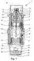
- Figs. 1 and 2show a proposed inhaler 1 for nebulising a fluid 2, particularly a medicament preparation, a highly potent drug or the like, in a schematic representation in the untensioned state ( Fig. 1 ) and in the tensioned state ( Fig. 2 ).
- the inhaler 1is constructed in particular as a portable inhaler and/or preferably operates without propellant gas.
- a respirable aerosol 14( Fig. 1 ) is formed which can be breathed in or inhaled by a user or patient (not shown). Normally, inhalation takes place at least once a day, but particularly several times a day, preferably at specified intervals of time, more particularly depending on the complaint.
- the inhaler 1is constructed in particular as a soft mist inhaler as described hereinbefore.
- the inhaler 1comprises a preferably insertable and optionally exchangeable container 3 holding the fluid 2.
- the container 3thus forms a reservoir for the fluid 2.
- the container 3contains a sufficient quantity of fluid 2 for multiple application or several doses of the fluid 2, particularly for a predetermined period of administration, such as a month, or for at least 50, preferably at least 100, doses or nebulisations.
- the container 3is preferably substantially cylindrical or cartridge-shaped and/or may be inserted in the inhaler 1 from below, for example, after the inhaler has been opened, and may optionally be replaceable. It is preferably of rigid construction, the medicament preparation 2 being held in a collapsible bag 4 in the container 3.
- a typical container 3 as disclosed in WO 96/06011 A1holds a volume of about 2 to 10 ml. With regard to the preferred construction of the container 3 reference is additionally made to WO 00/49988 A2 .
- the inhaler 1preferably has a conveying device or a pressure generator 5, for conveying and atomising the fluid 2, particularly in a predetermined, optionally adjustable metering quantity, i.e. for metered nebulisation or nebulisation in a plurality of defined doses.
- a conveying device or a pressure generator 5for conveying and atomising the fluid 2, particularly in a predetermined, optionally adjustable metering quantity, i.e. for metered nebulisation or nebulisation in a plurality of defined doses.
- a conveying device or a pressure generator 5for conveying and atomising the fluid 2, particularly in a predetermined, optionally adjustable metering quantity, i.e. for metered nebulisation or nebulisation in a plurality of defined doses.
- One doseis delivered on each actuation of the inhaler 1.
- the inhaler 1 or pressure generator 5is particularly designed so that the conveying, pressure generation and/or nebulisation take place without the use of propellants, mechanically and/or by the energy or force of an energy store, particularly a spring store, most preferably by the spring force of a drive spring 7, in the embodiment shown.
- an energy storeparticularly a spring store, most preferably by the spring force of a drive spring 7, in the embodiment shown.
- other design solutionsare also possible.
- the inhaler 1 or pressure generator 5comprises in particular a holder 6 for the container 3, the associated drive spring 7, which is only partly shown, preferably having an associated trigger element 8 which is manually operable to release it, a conveying element, preferably a conveying tube 9 in the form of a capillary, with an optional valve, particularly a non-return valve 10, a pressure chamber 11 and/or an expulsion nozzle 12, particularly in the region of an outlet or mouthpiece 13.
- the container 3is fixed in the inhaler 1 by means of the holder 6, particularly by a clamping or latching action, such that the conveying tube 9 protrudes into the container 3.
- the holder 6may be constructed such that the container 3 can be exchanged.
- the inhaler or pressure generator 5preferably comprises a tensioning device.
- the drive spring 7When the drive spring 7 is axially tensioned, the holder 6 with the container 3 and the conveying tube 9 is moved downwards in the figures and the fluid 2 - or more precisely the next dose - is sucked out of the container 3 into the pressure chamber. 11 of the pressure generator 5 through the non-return valve 10.
- the medicament preparation 2 in the pressure chamber 11is placed under pressure by moving the conveying element or conveying tube 9 back up, with the non-return valve 10 now closed, by releasing the tension on the drive spring 7, so that this conveying tube 9 now acts as a pressure ram.
- This pressureexpels the fluid 2 through the expulsion nozzle 12, where it is nebulised into the preferably respirable aerosol 14, as shown in Fig. 1 .
- the user or patientcan inhale the aerosol 14, while preferably supply air can be sucked into the mouthpiece 13 through at least one supply air opening 15, as indicated by dotted arrows 44 in Fig. 1 .
- the container 3is moved back into its original position by the drive spring 7.
- the container 3thus performs a lifting movement during the tensioning process and during the nebulisation process.
- the inhaler 1comprises in particular a first housing part (upper part) 16 and an inner part 17 which is rotatable relative thereto ( Fig. 2 ) having an upper part 17a and a lower part 17b ( Fig. 1 ), while a second housing part (lower part) 18, which is in particular manually operable or rotatable, is releasably attached, in particular pushed onto the inner part 17, preferably by means of a safety closure or retaining element 19.
- the safety closure or retaining element 19is constructed such that accidental opening of the inhaler 1 or removal of the second housing part 18 is prevented.
- the retaining element 19has to be pressed in against a spring force.
- the second housing part 18can be detached from the inhaler 1.
- the second housing part 18preferably forms a cap-like lower housing part and/or engages around or over a lower free end portion of the container 3.
- the drive spring 7, which is only partly shown,is held in the rotatable inner part 17 preferably by means of a ring 7a and/or acts axially preferably between the inner part 17 or ring 7a on the one hand and the axially movable holder 6 on the other hand.
- the second housing part 18can be rotated relative to the first housing part 16, whereby the inner part 17 is also rotated.
- the drive spring 7is tensioned in the axial direction by means of a gear (not shown in detail) acting on the holder 6, which acts in particular via a screw thread on the holder 6 or indirectly or directly.
- a gearnot shown in detail
- the container 3is moved axially downwards or with its end portion (further) into the second housing part 18 or towards the end face thereof, until the container 3 assumes an end position shown in Fig. 2 . In this state the drive spring 7 or inhaler 1 is clamped and locked.
- the tensioning device for tensioning the drive spring 7 or other energy or spring storecomprises, in particular, at least one rotatable part (actuating part), such as the second housing part 18 and/or inner part 17 and in this case preferably also the gear for converting the rotary movement into the linear, in this case axial, tensioning movement.
- the rotary movementis always continued in the same direction of rotation during tensioning; therefore, reverse rotation is not required.
- other design solutionsare also possible.
- the two housing parts 16 and 18preferably together form the housing or an outer housing of the inhaler 3.
- the mouthpiece 13is formed on the upper housing part 16 or is formed thereby.
- the lower housing part 18is preferably arranged on the end of the inhaler 1 opposite the delivery end or the mouthpiece 13. At this opposite end the inhaler 1 or its housing may also be capable of being opened, particularly for the insertion of the container 3.
- the actuating member for tensioning the inhaler 1 or the drive spring 7is preferably also located at this opposite end. This actuating member is formed by the housing part 18 in this case, as explained hereinbefore.
- the inhaler 1preferably has a device for forcibly ventilating the container 3.
- the container 3is preferably pierced or opened in its base.
- an axially acting spring 20 arranged in.the housing part 18comes to abut on the container base 21 and, with a piercing element 22, pierces the container 3 or an in particular gastight seal provided in the base for ventilation purposes when contact is first made.
- the device for forcible ventilationis thus formed in this case by the piercing element 22, which is held or formed by the spring 20.
- the piercing element 22which is held or formed by the spring 20.
- other design solutionsare also possible.
- the container 3In order to use the inhaler 1, first of all the container 3 has to be inserted. This is preferably done by removing or pulling out the second housing part 18. The container 3 is then axially inserted or pushed into the inner part 17. At the same time the container 3 is opened at the head end or attached. This is done by means of the conveying element, i.e. the conveying tube 9, which pierces a seal preferably provided at the head end of the container 3 and is then inserted through a septum at the head end of the container 3 into the interior of the bag 4.
- the conveying elementi.e. the conveying tube 9
- the conveying tube 9which pierces a seal preferably provided at the head end of the container 3 and is then inserted through a septum at the head end of the container 3 into the interior of the bag 4.
- the second housing part 18is pushed on again.
- the inhaler 1can now be tensioned for the first time.
- the container 3is then pierced at its base by the piercing element 22, i.e. forcibly ventilated, as explained previously.
- the inhaler 1is preferably tensioned and triggered several times. As a result of this so-called priming any air present in the conveying tube 9 and in the pressure generator 5 is displaced by the fluid 2 to the expulsion nozzle 12. The inhaler 1 is then ready for inhalation.
- the quantity of fluid 2 delivered per spray or nebulisation processis preferably about 10 ⁇ l to 50 ⁇ l, more particularly about 10 ⁇ l to 20 ⁇ l, most preferably about 15 ⁇ l.
- the drive spring 7is preferably installed in a biased state in order to achieve a high spring pressure.
- the pressurisation and conveying of the fluid 2 during the nebulisation processtakes place preferably only by spring force, and more particularly only by the force of the drive spring 7.
- the inhaler 1is preferably constructed such that the fluid 2 in the pressure generator 5 or in the pressure chamber 11 reaches a pressure of 5 MPa to 60 MPa, particularly about 10 MPa to 50 MPa during delivery. Particularly preferably, during the delivery or nebulisation, a pressure of about 5 MPa to 60 MPa, more particularly about 10 to 30 MPa, is reached at the expulsion nozzle 12 or at the nozzle openings thereof.
- the fluid 2is then converted into the aerosol 14, the droplets of which have an aerodynamic diameter of up to 20 ⁇ m, preferably about 3 ⁇ m to 10 ⁇ m.
- the nebulising activity or nebulising effectis achieved or further assisted by preferably intercepting jets delivered by the expulsion nozzle 12.
- the inhaler 1is preferably constructed such that the aerosol 14 is delivered at low speed, particularly at a speed of less than 2 m/s, most preferably about 1.6 m/s or less (in each case measured at a distance of 10 cm from the expulsion nozzle 12).
- the inhaler 1is thus preferably in the form of an SMI.
- the low dispensing speedcan be obtained or assisted by intercepting jets of the fluid 2, which are delivered by the expulsion nozzle 12 and/or by a suitable choice of spring force.
- the construction of the inhaler 1is such that the aerosol generation lasts for more than 0.7 s, preferably substantially 1 s or longer, in particular for more than 1.5 s.
- the time taken to nebulise a dose or to actuate the inhaler 1is thus preferably more than 0.75, more particularly about 1 s or more.
- the inhaler 1preferably comprises a counter 23 as schematically shown in Fig. 1 .
- the counter 23preferably operates purely mechanically and/or counts the tensioning of the inhaler 1 or the drive spring 7.
- the counter 23comprises a threaded spindle with an associated slider, the threaded spindle preferably being drivable by the rotation of the inner part 17 relative to the upper housing part 16.
- other design solutionsare also possible.
- the inhaler 1preferably comprises a monitoring device 24 for detecting uses of the inhaler 1.
- the monitoring device 24 in the first embodiment shownis preferably installed in the inhaler 1 or its housing, particularly preferably in the actuating member or housing part 18, as indicated in Figs. 1 and 2 .
- the monitoring device 24is preferably fixedly installed and/or cast, glued or clipped into the housing part 18.
- other design solutionsare also possible.
- the monitoring device 24preferably forms a module or unit.
- the monitoring device 24preferably comprises, in the embodiment shown, a printed circuit board 25 with components mounted thereon.
- the monitoring device 24preferably operates electronically.
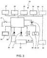
- the monitoring device 24preferably comprises a processor or microcontroller 26 for controlling the monitoring device 24, a time base or clock 27 (which may also be a timer or the like), a memory 28, a sensor 29 for measuring measured values corresponding to the current of supply air or dependent thereon, particularly pressure values (in the form of a pressure sensor in the embodiment shown), and/or at least one position sensor.
- a processor or microcontroller 26for controlling the monitoring device 24, a time base or clock 27 (which may also be a timer or the like), a memory 28, a sensor 29 for measuring measured values corresponding to the current of supply air or dependent thereon, particularly pressure values (in the form of a pressure sensor in the embodiment shown), and/or at least one position sensor.
- the monitoring device 24preferably has at least one position sensor, in this embodiment two position sensors, namely an acceleration sensor 30 and/or a GPS sensor 31, in particular.
- the memory 28is preferably non-volatile and/or rewritable.
- the acceleration sensor 30is, for example, a preferably three dimensionally measuring so-called MEMS-gyro-sensor.
- a sensor of this kindis able to detect the acceleration of the earth, for example, and thereby make it possible to detect the orientation of the inhaler 1.
- accelerationscan be measured or detected in every three dimensional direction using a sensor of this kind.
- a path of movement of the inhaler 1can be determined from these acceleration values taking account of the respective times. This determination may take place, as desired, in the monitoring device 24 or subsequently, by means of the corresponding data and information outside the monitoring device 24 or outside the inhaler 1.
- Acceleration sensors of this kindare used for example in cars, particularly for activating airbags in the case of accidents, and are therefore available at low cost.
- the GPS sensor 31makes it possible to detect the position of the inhaler 1 on Earth.
- the sensor 31makes use of the so-called Global Positioning System. However, position can be determined by any other suitable method.
- the charging of an accumulatorpreferably takes place by induction.
- the temperature measurement or detectionis carried out directly by means of the pressure sensor 29.
- Combined sensors of this kindare available at low cost.
- other solutions or constructionsare possible.
- the monitoring device 24preferably also comprises a temperature sensor, a moisture sensor 32 and/or an actuator 33.
- the monitoring device 24preferably also comprises an energy or current supply 34, particularly in the form of an accumulator or a battery, preferably a button-cell and/or comprising a photo-electric cell or solar cell or the like.
- the monitoring device 24 or inhaler 1preferably comprises at least one display device particularly an optical display device, particularly preferably a digital or other display such as a monitor screen or a display (display field) 35, preferably in the form of an LCD display, and/or at least one light-emitting diode, or a plurality of light emitting diodes 36 and 37 with different colours, as required, and/or an acoustic indicating means such as a loud speaker, buzzer 38 or the like.
- an optical display deviceparticularly a digital or other display such as a monitor screen or a display (display field) 35, preferably in the form of an LCD display, and/or at least one light-emitting diode, or a plurality of light emitting diodes 36 and 37 with different colours, as required, and/or an acoustic indicating means such as a loud speaker, buzzer 38 or the like.
- the monitoring device 24 or the optical display 35may if necessary also act as a dosage counter, particularly to indicate the number of doses of fluid 2 that have already been dispensed or are still to be dispensed.
- the flow rate of the breathingi.e., the flow speed when breathing in or the volume flow during breathing in can be determined from the pressure measurement.
- the monitoring device 24preferably comprises an interface 39 for the transmission of data, particularly for inputting or outputting data, particularly for outputting data relating to the use of the inhaler 1.
- the interface 39preferably operates optically or in the infrared range. This is particularly secure against unwanted listening-in or eavesdropping.
- the data transmissionmay also be effected by any other method, for example by radio or electrical contact of the transmission device 24 or printed circuit board 25 or via another electrical connection such as a plug or the like.
- For the issuing or transmission of datait is also possible to use generally known or special protocols or interfaces such as Bluetooth, USB, SATA or the like. Alternatively or additionally, the inductive transmission of data is also possible.
- the components and parts of the monitoring device 24are arranged on the printed circuit board 25 or connected thereto.
- individual components or partsmay also be arranged separately from it, particularly an optical display device such as the display 35 and/or the actuator 33 or the like. These parts or components are then preferably electrically connected to the transmission device 24 or printed circuit board 25 and/or are actuated accordingly by the transmission device 24.
- the monitoring device 24Individual components of the monitoring device 24, for example the clock 27, the memory 28, the pressure sensor 29, the position sensors and/or the moisture sensor 32, are preferably connected to the micro-controller 26 via a bus 40. However, connection may be made by some other means.
- the inhaler 1 or monitoring device 24preferably comprises a sensor or switch 41 for switching on, waking up and/or activating the monitoring device 24.
- the monitoring device 24is woken up, switched on or activated when the drive spring 7 of the inhaler 1 is tensioned and/or when a certain position of the container is reached, more particularly the bottom end position of the container or the position that the container 3 occupies when the inhaler 1 is tensioned (as shown in Fig. 2 ).
- Thisis carried out, particularly preferably, by the switch 41 being actuated and/or formed by the container 3 or the spring 20 associated with the container 3.
- the spring 20may form or comprise an electrical contact which opens and closes depending on the position of the container or the position of the spring 20.
- the switch 41co-operates with the container 3 or spring 20 or can be actuated thereby, for example via a contact or switching pin 42.
- the switch 41is in the form of a microswitch.
- any other suitable contact, switch or the likemay be used here.
- the switch 41may also be formed by a different sensor or the like.
- the switch 41 in the sense of the present inventionforms a sensor for waking up or switching on the monitoring device 24 when the drive spring 7 is tensioned or when a certain container position is reached, in this case the end position of the container when the inhaler 1 is tensioned.
- the spring 20may, if required, also form a unit with the monitoring device 24 and/or may be mechanically connected to the printed circuit board 25 or may be supported by or mounted on the latter.
- the monitoring device 24preferably comprises the pressure sensor 29 for measuring the air pressure in the housing of the inhaler 1, particularly reduced pressure or a pressure drop as the user (not shown) of the inhaler 1 breaths in or inhales.
- the pressure sensor 29serves to detect a current of supply air and hence an inhalation and thereby detect use of the inhaler 1.
- any other sensor 29may also be used, particularly a flow sensor or the like.
- a flow sensormay be incorporated as a sensor 29 of the monitoring device 24 for detecting the flow of supply air into the mouthpiece 13, as disclosed in WO 2005/080001 A1 , in particular.
- This sensor 29can then be connected to the monitoring device 24 for example via corresponding connections or a cable and/or it may transmit measured values by wireless operation.
- the monitoring device 24may also be inserted or incorporated directly in the mouthpiece 13 together with the sensor 29, particularly if it is suitably miniaturised.
- the sensor 29 usedis not a flow sensor but a pressure sensor. Tests have shown that sensors of this kind also make it possible to determine the flow of supply air and thereby detect breathing in or inhalation by a user in a surprisingly effective manner. As pressure sensors are available more cheaply than flow sensors, this results in a simpler and cheaper construction.
- the pressure sensor 29is mounted not in the mouthpiece 13 but outside the mouthpiece 13.
- the pressure sensor 29is arranged in the inhaler 1 or its housing separately from the mouthpiece 29, particularly in a separate spatial region which is fluidically connected to the mouthpiece 13 or a supply air pathway of the inhaler 1.
- the pressure sensor 29is arranged in the actuating part or housing part 18. In the embodiment shown, this space is fluidically connected, for example, via a bore or opening 43 in the upper housing part 16 to the mouthpiece 13 or supply air pathway 44 indicated by dotted lines in Fig. 1 .
- fluid connectionin the present invention is to be understood as meaning that a gaseous connection is provided which allows a sufficiently good equalisation of pressure and hence pressure measurement.
- the pressure sensor 29preferably provides a measurement or detection of a reduced pressure in the inhaler 1 or mouthpiece 13 which occurs during inhalation or breathing in by user (not shown) as a result of a throttle effect on the supply air opening or openings 15 for the current of supply air 44.
- the spatial separation of the pressure sensor 29 or other sensor from the mouthpiece 13 or delivering region of the inhaler 1gives rise to a number of advantages. Unwanted soiling of the sensor 29 can be avoided. Retrofitting of existing inhaler constructions is often easier.
- the monitoring device 24may form a module with the sensor 29. This in turn makes construction easier and particularly retrofitting.
- the monitoring device 24is preferably switched off, deactivated or in stand-by mode. It is switched on or activated or woken up, for example, by the switching on of the power supply 34. Preferably, the monitoring device 24 is automatically switched on, woken up or activated when the inhaler 1 is used, particularly when a mouthpiece cover (not shown) is opened or when the inhaler 1 or the drive spring 7 is tensioned, most preferably when a predetermined position of the container is reached, particularly the end position or tensioned position of the container 3 shown in Fig. 2 , with the inhaler 1 tensioned.
- Detecting the tensioning of the inhaler 1 or the reaching of a certain position of the container, such as the above-mentioned end position,is preferably done by the means of the sensor or switch 41. If in the embodiment shown the inhaler 1 is brought or transferred from the untensioned state shown in Fig. 1 into the tensioned state shown in Fig. 2 , the container 3 or the spring 20 operates the switch 41, particularly by means of the switching pin 42, thereby switching on or waking up or activating the monitoring device 24.
- the switch 41particularly by means of the switching pin 42, thereby switching on or waking up or activating the monitoring device 24.
- other design or method solutionsare also possible.
- the monitoring device 24After being switched on or activated or woken up, the monitoring device 24 measures the pressure (air pressure) preferably continuously or at short intervals, over and over again, by means of the pressure sensor 29.
- the monitoring device 24is thus designed particularly for determining a pressure pattern.
- the pressureis measured before the nebulisation of the fluid and then again during the fluid nebulisation.
- the pressure measurementmay optionally also take place before the breathing in or inhaling, e.g. sporadically at certain times or when the inhaler 1 is moved.
- the monitoring device 24is thus designed in particular to detect a pressure pattern beginning before inhalation and during inhalation and/or nebulisation and/or nebulisation.
- the detection of the nebulisationmay, however, take place in some other suitable manner, alternatively or additionally.
- a proximity sensormay be used, for example.
- an (additional) switchto be associated with the initiating element 8 or other suitable element of the inhaler 1 in order to detect the start of the nebulisation of fluid 2 or the actual nebulisation of fluid 2 or the triggering of the inhaler 1.
- a spray sensor or moisture sensor or the like in the mouthpiece 13for example, in order to be able to detect the actual production of the aerosol 14.
- the inhaler 1 and/or the start of nebulisationAfter the triggering of the inhaler 1 and/or the start of nebulisation has been detected, preferably measurement of the time of breathing in or inhaling is started. It is thus possible, for example, to detect and/or indicate, by means of the monitoring device 24, whether inhalation has continued for a sufficiently long time.
- the monitoring device 24can also evaluate and optionally indicate whether and to what extent there has been correct or adequate or proper co-ordination of the actuation of the inhaler 1 or nebulisation on the one hand and the breathing in or inhalation on the other hand.
- the pressure dataAfter the start of the nebulisation or after detecting the initiation of the inhaler 1, the pressure data go on being recorded and stored for a further period, for example, and/or until a certain threshold or a certain proportion of memory values in the cyclical buffer or cyclical memory (which may also be a predetermined memory region within the memory 29) of current memory values has been exceeded after the initiation of the inhaler 1 or the start of nebulisation.
- a certain threshold or a certain proportion of memory values in the cyclical buffer or cyclical memorywhich may also be a predetermined memory region within the memory 29
- an absolute number of memory values or a percentage number of memory valuescan be provided as a limit. In this way, it is possible to ensure that even before atomisation starts, pressure values measured continue to be stored, i.e. are not overwritten to more recent pressure values.
- other technical or procedural solutions or software solutionsare possible here as well.
- the pressure data and/or flow data or the like formed from themare stored by the monitoring device 24 and/or issued particularly through the interface 39.
- other data or parametersare detected, stored, indicated and/or issued, in particular the present time of day, date, duration of breathing in or inhalation or the like.
- These further datamay alternatively or additionally also include statistical data or evaluations, for example a lung volume calculated or estimated from the data, the dosage presumably taken by the user, or the like.
- the additional datamay also include the time delay between the start of breathing in or inhaling on the one hand and the start of the nebulisation or initiation of the inhaler 1, on the other hand, or other information or sensor values of measured values, particularly of the other sensors of the monitoring device 24.
- the further data or informationmay include in particular relative or absolute times and/or durations between different events such as different uses of the inhaler 1.
- the further data and informationmay also relate to the position, orientation and/or acceleration of the inhaler 1 or a path of movement of the inhaler 1.
- the monitoring device 24can detect and correspondingly store and/or indicate an absolute position and/or orientation of the inhaler 1 in space and/or alterations or accelerations or the like relating to it.
- a path of movement of the inhaler 1can also be determined from acceleration values or data, taking account of the time of the actual detection or measurement. This provides useful information, for example, with regard to correct handling of the inhaler 1.
- the expression "detecting uses of the inhaler 1"refers to the measuring, detection, storage, output and/or evaluation of one or more of the above-mentioned data and/or items of information. Particularly preferably, it includes, at least, detecting the breathing in or inhaling and/or detecting actuations of the inhaler 1 or movements of the container 3.
- the various data and informationare displayed, stored and/or given out.
- theymay be provided through the interface 39 and/or by any other suitable method.
- the output or transmission of datamay take place after every use of the inhaler 1 or at any other desired time or event, for example after the emptying of the container 3.
- the transmission device 24may communicate with or be coupled to a corresponding communications or reading device (not shown), particularly via the interface 39.
- a corresponding communications or reading devicenot shown
- the monitoring device 24 or the housing part 18may be separated from the inhaler 1 as required.
- the monitoring device 24may also be designed for user information or user guidance.
- user guidancemay take the form of an acoustic and/or optical display or the issuing of corresponding data, information and/or instructions.
- a status or an error or a possibility of improvementcan be indicated using the display 35 or some other method.
- the respective status of the monitoring device 24can be indicated for example by means of the light emitting diodes 36 and 37 or in some other way.
- the monitoring device 24can also indicate to the user optically and/or acoustically, for example, how long and/or how powerfully he has to breath in and/or inhale and/or when the end of the (required) inhalation is reached.
- the housing part 18is preferably at least partly transparent in construction. Accordingly, an optical display through the housing part 18 may be provided as necessary. Corresponding components such as the display 35 and/or the light emitting diodes 36 and 37 may therefore be arranged directly on the printed circuit board 25.
- the initiation of the inhaler 1 or drive spring 7 or the start of the nebulisationmay also take place automatically, if necessary, in the embodiment shown, particularly if the monitoring device 24 detects (sufficiently strong) breathing in or inhalation by the user.
- the monitoring device 24 or the micro-controller 26may initiate the nebulisation of fluid 2 via the optional actuator 33, for example.
- the actuator 33may release the tension on the drive spring 7 or actuate the initiating element 8 accordingly. In this way, breath-controlled nebulisation can be achieved.
- the actuator 33 and/or another optional actuatormay also be used to prevent further actuation or triggering of the inhaler 1, for example at the end of a specified period of use or after a certain predetermined number of doses has been given, and the inhaler 1 is then controlled accordingly by the monitoring device 24.
- Blockingmay alternatively or additionally be provided, for example, as a temporary measure to prevent overdosing, particularly when active substances with an addictive potential are being administered.
- the housing of the inhaler 1 or the lower housing part 18is preferably sealed off from the housing part 16 by means of corresponding seals or the like (not shown), particularly relative to the housing part 16, such that the pressure that can be measured by the pressure sensor 29 at least substantially corresponds to the pressure in the mouthpiece 13 or supply air pathway 44. Besides a "sufficient" seal this may also be achieved or at least assisted by correspondingly large connecting cross-sections, particularly between the mouthpiece 13 and the spatial region in which the pressure sensor 29 is located, and, in the embodiment shown, particularly by a sufficiently large opening 43.
- the monitoring device 24is constructed so that it automatically switches off or is deactivated or goes into standby mode after a certain (first) period of time, starting from the nebulisation or triggering of the inhaler 1. If after the tensioning of the inhaler 1 there is no nebulisation or triggering, automatic switching off, deactivation or switching to standby mode preferably also takes place after a (second) period of time has expired after the waking up or activation of the monitoring device 24, i.e., after the detection of the tensioning of the inhaler 1 or the predetermined container position. If then the inhaler 1 or fluid nebulisation is still initiated, the monitoring device 24 may optionally be switched on or activated or woken up again.
- the monitoring device 24may be activated or woken up or the power supply 34 may be switched on by the detection of movement of the inhaler 1 (particularly if a change in the position and/or orientation of the inhaler 1 is detected), particularly by means of the acceleration sensor 30 or by means of another jolt or shake sensor.
- the temperature and/or moisture values which are optionally additionally measuredare used as correction values, particularly for correcting when determining the current of supply air and/or when determining the dose of fluid or active substance taken by the user (so called lung dose).
- these valuesmay also be used to provide information as to the actual use or ambient conditions under which the inhaler 1 is used.
- the inhaler 1 or monitoring device 24is preferably also designed to measure, detect, store, determine, evaluate, indicate and/or issue the data, information, numerical values and the like, as described in WO 2005/080001 A1 .
- the fluid 2may be an aqueous or non-aqueous solution, mixture, formulation with or without solvents, such as ethanol or the like.
- the fluid 2may be an aqueous or non-aqueous solution, mixture, formulation with or without solvents, such as ethanol or the like.
Landscapes
- Health & Medical Sciences (AREA)
- Engineering & Computer Science (AREA)
- Life Sciences & Earth Sciences (AREA)
- General Health & Medical Sciences (AREA)
- Veterinary Medicine (AREA)
- Hematology (AREA)
- Biomedical Technology (AREA)
- Animal Behavior & Ethology (AREA)
- Anesthesiology (AREA)
- Public Health (AREA)
- Heart & Thoracic Surgery (AREA)
- Bioinformatics & Cheminformatics (AREA)
- Pulmonology (AREA)
- Biophysics (AREA)
- Mechanical Engineering (AREA)
- Medicinal Preparation (AREA)
- Containers And Packaging Bodies Having A Special Means To Remove Contents (AREA)
Description
- The present invention relates to an inhaler according to the preamble of
claim 1. WO 2005/080001 A1 discloses an inhaler having a monitoring device for detecting actuations. The known inhaler comprises, as a reservoir for a medicament preparation that is to be nebulised, a rigid insertable container having an inner bag containing the medicament preparation and a pressure generator having a drive spring for conveying and nebulising the medicament preparation. Nebulisation is carried out without the use of a propellant gas, namely by.the force of the drive spring. The drive spring can be tensioned by rotating an actuating member in the form of a lower housing part of the inhaler and the medicament preparation can be sucked into a pressure chamber of the pressure generator. After manual operation of a blocking element, the medicament preparation in the pressure chamber is put under pressure by the drive spring and atomised, i.e. expelled, forming an aerosol. During the tensioning, on the one hand, and the subsequent nebulisation, on the other hand, the container performs a lifting movement each time. The monitoring device is installed in the lower housing part and may comprise a flow sensor in a mouthpiece of the inhaler for detecting a stream of supply air and hence an inhalation.WO 2005/080001 A1 relates to an inhaler. The inhaler comprises an insertable container and a monitoring device for counting actuations. The inhaler has a sensor for waking up and switching on the monitoring device.WO 97/48431 US 5,363,842 A discloses an inhaler providing feedback to a patient and a medical professional. The inhaler comprises an insertable container containing a fluid and a monitoring device. The monitoring device has a pressure sensor and a motion sensor. Properly shaking of the inhaler is monitored by the motion sensor.WO 2008/142015 A2 relates to a dispenser and a method for operating a dispenser. The dispenser discloses different sensor types for detecting a movement. The motion sensor can be formed as a GPS-sensor. The sensors are adapted to detect shaking and/or mixing. Further, the sensors can detect the physical activity of a user.US 2009/0156952 A1 relates to a respiratory condition device including a tube that defines a flow path for medicine that is to be delivered to a user respiratory system, a pressure sensor configured to detect pressure changes within the tube, and a medicine delivery device configured to eject medicine into the tube when a pressure drop is detected by the pressure sensor.- The aim of the present invention is to provide an inhaler having an improved and/or simplified monitoring device, particularly allowing improved reliability in use and/or more information as to the user and/or improved monitoring of the user.
- The above aim is achieved by an inhaler according to
claim 1. Advantageous further features are the subject of the subsidiary claims. - According to one aspect, the monitoring device comprises a pressure sensor for measuring the air pressure in a housing of the inhaler or the monitoring device, particularly in a mouthpiece of the inhaler, for detecting inhalation. This results in a very simple design that is cheap to produce. In particular, a pressure sensor of very simple construction can be used instead of a flow sensor. Moreover, the pressure sensor can be arranged separately from the
mouthpiece, in particular outside the mouthpiece, but preferably within the inhaler in another region, most preferably in the lower actuating or housing part. This preferred arrangement of the pressure sensor outside a path for supply air allows a particularly simple construction. - According to another aspect of the present invention, the monitoring device comprises at least one position sensor for detecting a position, orientation and/or acceleration of the inhaler. This allows improved monitoring of actual use. In particular it makes it possible to determine a path of movement of the inhaler.
- According to another aspect, the monitoring device comprises a sensor or switch for waking up, activating or switching on the monitoring device particularly during tensioning of a drive spring of the inhaler or when a particular container position is reached or during other activation of the inhaler for use, for example when opening a mouthpiece cover. This results in a particularly low-energy or low-powered mode of operation. In particular, the monitoring device is at least substantially switched on or woken up or activated only when the inhaler is actually about to be used or being used. Accordingly it is readily possible to achieve increased security of use or increased security in user monitoring.
- Preferably, the inhaler or the monitoring device is designed so that after use has ended or a use has been detected, particularly after an inhalation, and optionally also after a predetermined length of time, the monitoring device is switched off or deactivated or switched to standby mode, particularly automatically.
- According to another aspect, the monitoring device is designed to cover one or more supply air openings in the inhaler, particularly supply air openings in a mouthpiece of the inhaler, and/or to form a supply air pathway, particularly preferably the only supply air pathway of the inhaler. This makes it possible in particular to fit the monitoring device to existing inhaler constructions. Thus, a stream of supply air during inhalation can be very easily measured or detected outside a mouthpiece or inhaler and in this way use of the inhaler can be detected or determined.
- According to another aspect, the monitoring device can be placed or fitted onto the mouthplece. According to the invention the monitoring device comprises a separate housing that is detached from or detachable from the inhaler. This allows easy modification of existing inhaler constructions and/or easy separation of the monitoring device, for example in order to read out data from the monitoring device.
- According to an alternative aspect, the monitoring device is mounted on a detachable housing part of the inhaler, particularly firmly connected thereto, preferably installed therein, for example cast therein. This permits easy release of the monitoring device together with the housing part from the inhaler, so that the monitoring device can very easily be switched on, programmed, reset and/or read out - separately from or independently of the inhaler - and/or so that it is very easy to carry out total replacement of the monitoring device together with the housing part or retrofitting of an inhaler with a monitoring device, provided that the housing part is compatible.
- The monitoring device or the inhaler may comprise an actuator in order to initiate the nebulisation of fluid automatically when an inhalation is determined or detected, i.e. to carry out breath-controlled nebulisation, and/or temporarily block actuation of the inhaler or nebulisation, for example in order to adhere to a waiting time or avoid overdosing.
- The above-mentioned aspects of the present invention and the further aspects of the present invention that will become apparent from the following description may be implemented independently of one another, but also in any desired combination.
- The present invention relates in particular to a so-called soft-mist-inhaler (SMI), i.e. an inhaler which produces a spray mist (aerosol) that spreads out relatively slowly. Inhalers of this kind for the purposes of the present invention are, in particular, inhalers in which an aerosol is delivered at a speed of less than 2 m/s, preferably about 1.6 m/s or less and most particularly preferably less than 1 m/s, (measured in each case at a spacing of 10 cm from a delivery nozzle) and/or wherein the delivery or nebulisation of a dose - of preferably 10 to 50 µl of a medicament preparation - lasts longer than 0.7 s, more particularly about 1 s or longer.
- Further advantages, features, properties and aspects of the inhaler arise from the following description of preferred embodiments with reference to the drawings, wherein:
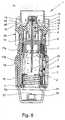
Fig. 1 is a schematic section through a proposed inhaler according to a first embodiment in the untensioned state;Fig. 2 is a schematic section, rotated through 90° compared withFig. 1 , through the inhaler in the tensioned state;Fig. 3 is a block circuit diagram of a monitoring device of the inhaler;Fig. 4 is a perspective front view of a proposed inhaler with a coupled or added monitoring device according to a second embodiment and according to the invention;Fig. 5 is a perspective rear view of the inhaler according toFig. 4 ;Fig. 6 is a schematic section through the inhaler according toFig. 4 in a section plane corresponding toFig. 1 ; andFig. 7 is a schematic section through the inhaler according toFig. 4 in a section plane corresponding toFig. 2 .- In the figures, the same reference numerals have been used for identical or similar components, where corresponding or comparable properties and advantages are obtained even though the associated description is not repeated.
Figs. 1 and2 show a proposedinhaler 1 for nebulising afluid 2, particularly a medicament preparation, a highly potent drug or the like, in a schematic representation in the untensioned state (Fig. 1 ) and in the tensioned state (Fig. 2 ). Theinhaler 1 is constructed in particular as a portable inhaler and/or preferably operates without propellant gas.- During the nebulisation of the
fluid 2, preferably a liquid, a respirable aerosol 14 (Fig. 1 ) is formed which can be breathed in or inhaled by a user or patient (not shown). Normally, inhalation takes place at least once a day, but particularly several times a day, preferably at specified intervals of time, more particularly depending on the complaint. - The
inhaler 1 is constructed in particular as a soft mist inhaler as described hereinbefore. - The
inhaler 1 comprises a preferably insertable and optionallyexchangeable container 3 holding thefluid 2. Thecontainer 3 thus forms a reservoir for thefluid 2. Preferably, thecontainer 3 contains a sufficient quantity offluid 2 for multiple application or several doses of thefluid 2, particularly for a predetermined period of administration, such as a month, or for at least 50, preferably at least 100, doses or nebulisations. - The
container 3 is preferably substantially cylindrical or cartridge-shaped and/or may be inserted in theinhaler 1 from below, for example, after the inhaler has been opened, and may optionally be replaceable. It is preferably of rigid construction, themedicament preparation 2 being held in acollapsible bag 4 in thecontainer 3. Atypical container 3 as disclosed inWO 96/06011 A1 container 3 reference is additionally made toWO 00/49988 A2 - The
inhaler 1 preferably has a conveying device or apressure generator 5, for conveying and atomising thefluid 2, particularly in a predetermined, optionally adjustable metering quantity, i.e. for metered nebulisation or nebulisation in a plurality of defined doses. One dose is delivered on each actuation of theinhaler 1. - The
inhaler 1 orpressure generator 5 is particularly designed so that the conveying, pressure generation and/or nebulisation take place without the use of propellants, mechanically and/or by the energy or force of an energy store, particularly a spring store, most preferably by the spring force of adrive spring 7, in the embodiment shown. However, other design solutions are also possible. - The
inhaler 1 orpressure generator 5 comprises in particular aholder 6 for thecontainer 3, the associateddrive spring 7, which is only partly shown, preferably having an associatedtrigger element 8 which is manually operable to release it, a conveying element, preferably a conveyingtube 9 in the form of a capillary, with an optional valve, particularly anon-return valve 10, apressure chamber 11 and/or anexpulsion nozzle 12, particularly in the region of an outlet ormouthpiece 13. - The
container 3 is fixed in theinhaler 1 by means of theholder 6, particularly by a clamping or latching action, such that the conveyingtube 9 protrudes into thecontainer 3. Theholder 6 may be constructed such that thecontainer 3 can be exchanged. - For tensioning the
drive spring 7 the inhaler orpressure generator 5 preferably comprises a tensioning device. When thedrive spring 7 is axially tensioned, theholder 6 with thecontainer 3 and the conveyingtube 9 is moved downwards in the figures and the fluid 2 - or more precisely the next dose - is sucked out of thecontainer 3 into the pressure chamber. 11 of thepressure generator 5 through thenon-return valve 10. - During the subsequent relaxation of the
drive spring 7 after operation of thetrigger element 8, themedicament preparation 2 in thepressure chamber 11 is placed under pressure by moving the conveying element or conveyingtube 9 back up, with thenon-return valve 10 now closed, by releasing the tension on thedrive spring 7, so that this conveyingtube 9 now acts as a pressure ram. This pressure expels thefluid 2 through theexpulsion nozzle 12, where it is nebulised into the preferablyrespirable aerosol 14, as shown inFig. 1 . - The user or patient (not shown) can inhale the
aerosol 14, while preferably supply air can be sucked into themouthpiece 13 through at least onesupply air opening 15, as indicated by dottedarrows 44 inFig. 1 . - During the nebulisation process, which is independent of the inhalation or respiration by the user, the
container 3 is moved back into its original position by thedrive spring 7. Thecontainer 3 thus performs a lifting movement during the tensioning process and during the nebulisation process. - The
inhaler 1 comprises in particular a first housing part (upper part) 16 and aninner part 17 which is rotatable relative thereto (Fig. 2 ) having anupper part 17a and alower part 17b (Fig. 1 ), while a second housing part (lower part) 18, which is in particular manually operable or rotatable, is releasably attached, in particular pushed onto theinner part 17, preferably by means of a safety closure or retainingelement 19. In particular, the safety closure or retainingelement 19 is constructed such that accidental opening of theinhaler 1 or removal of thesecond housing part 18 is prevented. In particular, in order to release thesecond housing part 18, the retainingelement 19 has to be pressed in against a spring force. In order to insert and/or replace thecontainer 3, thesecond housing part 18 can be detached from theinhaler 1. Thesecond housing part 18 preferably forms a cap-like lower housing part and/or engages around or over a lower free end portion of thecontainer 3. - The
drive spring 7, which is only partly shown, is held in the rotatableinner part 17 preferably by means of aring 7a and/or acts axially preferably between theinner part 17 orring 7a on the one hand and the axiallymovable holder 6 on the other hand. - The
second housing part 18 can be rotated relative to thefirst housing part 16, whereby theinner part 17 is also rotated. In this way thedrive spring 7 is tensioned in the axial direction by means of a gear (not shown in detail) acting on theholder 6, which acts in particular via a screw thread on theholder 6 or indirectly or directly. During tensioning thecontainer 3 is moved axially downwards or with its end portion (further) into thesecond housing part 18 or towards the end face thereof, until thecontainer 3 assumes an end position shown inFig. 2 . In this state thedrive spring 7 orinhaler 1 is clamped and locked. - In the embodiment shown, the tensioning device for tensioning the
drive spring 7 or other energy or spring store comprises, in particular, at least one rotatable part (actuating part), such as thesecond housing part 18 and/orinner part 17 and in this case preferably also the gear for converting the rotary movement into the linear, in this case axial, tensioning movement. Preferably, the rotary movement is always continued in the same direction of rotation during tensioning; therefore, reverse rotation is not required. However, other design solutions are also possible. - The two
housing parts inhaler 3. Preferably, themouthpiece 13 is formed on theupper housing part 16 or is formed thereby. Thelower housing part 18 is preferably arranged on the end of theinhaler 1 opposite the delivery end or themouthpiece 13. At this opposite end theinhaler 1 or its housing may also be capable of being opened, particularly for the insertion of thecontainer 3. The actuating member for tensioning theinhaler 1 or thedrive spring 7 is preferably also located at this opposite end. This actuating member is formed by thehousing part 18 in this case, as explained hereinbefore. - The
inhaler 1 preferably has a device for forcibly ventilating thecontainer 3. When tensioning first takes place, thecontainer 3 is preferably pierced or opened in its base. In particular, anaxially acting spring 20 arranged in.thehousing part 18 comes to abut on thecontainer base 21 and, with a piercingelement 22, pierces thecontainer 3 or an in particular gastight seal provided in the base for ventilation purposes when contact is first made. - The device for forcible ventilation is thus formed in this case by the piercing
element 22, which is held or formed by thespring 20. However, other design solutions are also possible. - It should be noted that during the piercing for ventilation purposes only the preferably rigid
outer shell 3a of thecontainer 3 or a related seal or the like is opened. Thebag 4 containing thefluid 2 remains undamaged. As thefluid 2 is removed from thebag 4 through the conveyingtube 9 theflexible bag 4 collapses. For pressure equalisation, ambient air can flow into thecontainer 3 through the ventilation or piercing opening. - In order to use the
inhaler 1, first of all thecontainer 3 has to be inserted. This is preferably done by removing or pulling out thesecond housing part 18. Thecontainer 3 is then axially inserted or pushed into theinner part 17. At the same time thecontainer 3 is opened at the head end or attached. This is done by means of the conveying element, i.e. the conveyingtube 9, which pierces a seal preferably provided at the head end of thecontainer 3 and is then inserted through a septum at the head end of thecontainer 3 into the interior of thebag 4. Thus the fluidic connection between thecontainer 3, or more accurately between thebag 4 in thecontainer 3, via the conveyingtube 9 to thepressure generator 5 orpressure chamber 11 is produced. - Then the
second housing part 18 is pushed on again. Theinhaler 1 can now be tensioned for the first time. At this stage thecontainer 3 is then pierced at its base by the piercingelement 22, i.e. forcibly ventilated, as explained previously. - After the
container 3 has been inserted and fluidically connected and before it is used for the first time, theinhaler 1 is preferably tensioned and triggered several times. As a result of this so-called priming any air present in the conveyingtube 9 and in thepressure generator 5 is displaced by thefluid 2 to theexpulsion nozzle 12. Theinhaler 1 is then ready for inhalation. - The quantity of
fluid 2 delivered per spray or nebulisation process is preferably about 10 µl to 50 µl, more particularly about 10 µl to 20 µl, most preferably about 15 µl. - The
drive spring 7 is preferably installed in a biased state in order to achieve a high spring pressure. In fact, in the proposedinhaler 1 the pressurisation and conveying of thefluid 2 during the nebulisation process takes place preferably only by spring force, and more particularly only by the force of thedrive spring 7. - The
inhaler 1 is preferably constructed such that thefluid 2 in thepressure generator 5 or in thepressure chamber 11 reaches a pressure of 5 MPa to 60 MPa, particularly about 10 MPa to 50 MPa during delivery. Particularly preferably, during the delivery or nebulisation, a pressure of about 5 MPa to 60 MPa, more particularly about 10 to 30 MPa, is reached at theexpulsion nozzle 12 or at the nozzle openings thereof. Thefluid 2 is then converted into theaerosol 14, the droplets of which have an aerodynamic diameter of up to 20 µm, preferably about 3 µm to 10 µm. The nebulising activity or nebulising effect is achieved or further assisted by preferably intercepting jets delivered by theexpulsion nozzle 12. - The
inhaler 1 is preferably constructed such that theaerosol 14 is delivered at low speed, particularly at a speed of less than 2 m/s, most preferably about 1.6 m/s or less (in each case measured at a distance of 10 cm from the expulsion nozzle 12). Theinhaler 1 is thus preferably in the form of an SMI. The low dispensing speed can be obtained or assisted by intercepting jets of thefluid 2, which are delivered by theexpulsion nozzle 12 and/or by a suitable choice of spring force. - Particularly preferably, the construction of the
inhaler 1 is such that the aerosol generation lasts for more than 0.7 s, preferably substantially 1 s or longer, in particular for more than 1.5 s. The time taken to nebulise a dose or to actuate theinhaler 1 is thus preferably more than 0.75, more particularly about 1 s or more. - The
inhaler 1 preferably comprises acounter 23 as schematically shown inFig. 1 . Thecounter 23 preferably operates purely mechanically and/or counts the tensioning of theinhaler 1 or thedrive spring 7. For example thecounter 23 comprises a threaded spindle with an associated slider, the threaded spindle preferably being drivable by the rotation of theinner part 17 relative to theupper housing part 16. However, other design solutions are also possible. - The
inhaler 1 preferably comprises amonitoring device 24 for detecting uses of theinhaler 1. Themonitoring device 24 in the first embodiment shown is preferably installed in theinhaler 1 or its housing, particularly preferably in the actuating member orhousing part 18, as indicated inFigs. 1 and2 . - The
monitoring device 24 is preferably fixedly installed and/or cast, glued or clipped into thehousing part 18. However, other design solutions are also possible. - The
monitoring device 24 preferably forms a module or unit. - The
monitoring device 24 preferably comprises, in the embodiment shown, a printedcircuit board 25 with components mounted thereon. - The
monitoring device 24 preferably operates electronically. - A preferred construction of the
monitoring device 24 is described in more detail hereinafter with reference to the schematic block circuit diagram shown inFig. 3 . Themonitoring device 24 preferably comprises a processor ormicrocontroller 26 for controlling themonitoring device 24, a time base or clock 27 (which may also be a timer or the like), amemory 28, asensor 29 for measuring measured values corresponding to the current of supply air or dependent thereon, particularly pressure values (in the form of a pressure sensor in the embodiment shown), and/or at least one position sensor. - The
monitoring device 24 preferably has at least one position sensor, in this embodiment two position sensors, namely anacceleration sensor 30 and/or aGPS sensor 31, in particular. - The
memory 28 is preferably non-volatile and/or rewritable. - The
acceleration sensor 30 is, for example, a preferably three dimensionally measuring so-called MEMS-gyro-sensor. A sensor of this kind is able to detect the acceleration of the earth, for example, and thereby make it possible to detect the orientation of theinhaler 1. Moreover, accelerations can be measured or detected in every three dimensional direction using a sensor of this kind. A path of movement of theinhaler 1 can be determined from these acceleration values taking account of the respective times. This determination may take place, as desired, in themonitoring device 24 or subsequently, by means of the corresponding data and information outside themonitoring device 24 or outside theinhaler 1. - Acceleration sensors of this kind are used for example in cars, particularly for activating airbags in the case of accidents, and are therefore available at low cost. The
GPS sensor 31 makes it possible to detect the position of theinhaler 1 on Earth. Thesensor 31 makes use of the so-called Global Positioning System. However, position can be determined by any other suitable method. - The charging of an accumulator preferably takes place by induction.
- Particularly preferably the temperature measurement or detection is carried out directly by means of the
pressure sensor 29. Combined sensors of this kind are available at low cost. However, once again other solutions or constructions are possible. - The
monitoring device 24 preferably also comprises a temperature sensor, amoisture sensor 32 and/or anactuator 33. - The
monitoring device 24 preferably also comprises an energy orcurrent supply 34, particularly in the form of an accumulator or a battery, preferably a button-cell and/or comprising a photo-electric cell or solar cell or the like. - The
monitoring device 24 orinhaler 1 preferably comprises at least one display device particularly an optical display device, particularly preferably a digital or other display such as a monitor screen or a display (display field) 35, preferably in the form of an LCD display, and/or at least one light-emitting diode, or a plurality oflight emitting diodes buzzer 38 or the like. - The
monitoring device 24 or theoptical display 35 may if necessary also act as a dosage counter, particularly to indicate the number of doses offluid 2 that have already been dispensed or are still to be dispensed. - When the flow resistance is known, the flow rate of the breathing, i.e., the flow speed when breathing in or the volume flow during breathing in can be determined from the pressure measurement.
- The
monitoring device 24 preferably comprises aninterface 39 for the transmission of data, particularly for inputting or outputting data, particularly for outputting data relating to the use of theinhaler 1. Theinterface 39 preferably operates optically or in the infrared range. This is particularly secure against unwanted listening-in or eavesdropping. However, the data transmission may also be effected by any other method, for example by radio or electrical contact of thetransmission device 24 or printedcircuit board 25 or via another electrical connection such as a plug or the like. For the issuing or transmission of data it is also possible to use generally known or special protocols or interfaces such as Bluetooth, USB, SATA or the like. Alternatively or additionally, the inductive transmission of data is also possible. - Preferably, most or all of the components and parts of the
monitoring device 24 are arranged on the printedcircuit board 25 or connected thereto. However, individual components or parts may also be arranged separately from it, particularly an optical display device such as thedisplay 35 and/or theactuator 33 or the like. These parts or components are then preferably electrically connected to thetransmission device 24 or printedcircuit board 25 and/or are actuated accordingly by thetransmission device 24. - Individual components of the
monitoring device 24, for example theclock 27, thememory 28, thepressure sensor 29, the position sensors and/or themoisture sensor 32, are preferably connected to themicro-controller 26 via abus 40. However, connection may be made by some other means. - The
inhaler 1 ormonitoring device 24 preferably comprises a sensor or switch 41 for switching on, waking up and/or activating themonitoring device 24. - Particularly preferably, the
monitoring device 24 is woken up, switched on or activated when thedrive spring 7 of theinhaler 1 is tensioned and/or when a certain position of the container is reached, more particularly the bottom end position of the container or the position that thecontainer 3 occupies when theinhaler 1 is tensioned (as shown inFig. 2 ). This is carried out, particularly preferably, by theswitch 41 being actuated and/or formed by thecontainer 3 or thespring 20 associated with thecontainer 3. For example, thespring 20 may form or comprise an electrical contact which opens and closes depending on the position of the container or the position of thespring 20.Fig. 2 schematically shows how theswitch 41 co-operates with thecontainer 3 orspring 20 or can be actuated thereby, for example via a contact or switchingpin 42. In particular, theswitch 41 is in the form of a microswitch. However, any other suitable contact, switch or the like may be used here. Furthermore, theswitch 41 may also be formed by a different sensor or the like. In particular, theswitch 41 in the sense of the present invention forms a sensor for waking up or switching on themonitoring device 24 when thedrive spring 7 is tensioned or when a certain container position is reached, in this case the end position of the container when theinhaler 1 is tensioned. - The
spring 20 may, if required, also form a unit with themonitoring device 24 and/or may be mechanically connected to the printedcircuit board 25 or may be supported by or mounted on the latter. - The
monitoring device 24 preferably comprises thepressure sensor 29 for measuring the air pressure in the housing of theinhaler 1, particularly reduced pressure or a pressure drop as the user (not shown) of theinhaler 1 breaths in or inhales. Thepressure sensor 29 serves to detect a current of supply air and hence an inhalation and thereby detect use of theinhaler 1. - Instead of the
pressure sensor 29, however, anyother sensor 29 may also be used, particularly a flow sensor or the like. For example, a flow sensor may be incorporated as asensor 29 of themonitoring device 24 for detecting the flow of supply air into themouthpiece 13, as disclosed inWO 2005/080001 A1 , in particular. Thissensor 29 can then be connected to themonitoring device 24 for example via corresponding connections or a cable and/or it may transmit measured values by wireless operation. Alternatively, themonitoring device 24 may also be inserted or incorporated directly in themouthpiece 13 together with thesensor 29, particularly if it is suitably miniaturised. - In the embodiment shown, however, the
sensor 29 used is not a flow sensor but a pressure sensor. Tests have shown that sensors of this kind also make it possible to determine the flow of supply air and thereby detect breathing in or inhalation by a user in a surprisingly effective manner. As pressure sensors are available more cheaply than flow sensors, this results in a simpler and cheaper construction. - Particularly preferably, the
pressure sensor 29 is mounted not in themouthpiece 13 but outside themouthpiece 13. Particularly preferably, thepressure sensor 29 is arranged in theinhaler 1 or its housing separately from themouthpiece 29, particularly in a separate spatial region which is fluidically connected to themouthpiece 13 or a supply air pathway of theinhaler 1. In the embodiment shown, thepressure sensor 29 is arranged in the actuating part orhousing part 18. In the embodiment shown, this space is fluidically connected, for example, via a bore or opening 43 in theupper housing part 16 to themouthpiece 13 orsupply air pathway 44 indicated by dotted lines inFig. 1 . The expression "fluidic connection" in the present invention is to be understood as meaning that a gaseous connection is provided which allows a sufficiently good equalisation of pressure and hence pressure measurement. Thus, thepressure sensor 29 preferably provides a measurement or detection of a reduced pressure in theinhaler 1 ormouthpiece 13 which occurs during inhalation or breathing in by user (not shown) as a result of a throttle effect on the supply air opening oropenings 15 for the current ofsupply air 44. - The spatial separation of the
pressure sensor 29 or other sensor from themouthpiece 13 or delivering region of theinhaler 1 gives rise to a number of advantages. Unwanted soiling of thesensor 29 can be avoided. Retrofitting of existing inhaler constructions is often easier. Themonitoring device 24 may form a module with thesensor 29. This in turn makes construction easier and particularly retrofitting. - If the
inhaler 6 is not in use, themonitoring device 24 is preferably switched off, deactivated or in stand-by mode. It is switched on or activated or woken up, for example, by the switching on of thepower supply 34. Preferably, themonitoring device 24 is automatically switched on, woken up or activated when theinhaler 1 is used, particularly when a mouthpiece cover (not shown) is opened or when theinhaler 1 or thedrive spring 7 is tensioned, most preferably when a predetermined position of the container is reached, particularly the end position or tensioned position of thecontainer 3 shown inFig. 2 , with theinhaler 1 tensioned. Detecting the tensioning of theinhaler 1 or the reaching of a certain position of the container, such as the above-mentioned end position, is preferably done by the means of the sensor orswitch 41. If in the embodiment shown theinhaler 1 is brought or transferred from the untensioned state shown inFig. 1 into the tensioned state shown inFig. 2 , thecontainer 3 or thespring 20 operates theswitch 41, particularly by means of the switchingpin 42, thereby switching on or waking up or activating themonitoring device 24. However, other design or method solutions are also possible. - After being switched on or activated or woken up, the
monitoring device 24 measures the pressure (air pressure) preferably continuously or at short intervals, over and over again, by means of thepressure sensor 29. Themonitoring device 24 is thus designed particularly for determining a pressure pattern. - If, after the tensioning of the
inhaler 1 or after themonitoring device 24 has been switched on or activated, a user breaths in or inhales through themouthpiece 13 or other delivery section of theinhaler 1, air is sucked in through thesupply air pathway 44. A reduced pressure is thereby produced in theinhaler 1 ormouthpiece 13. This reduced pressure is measured or detected or determined by thepressure sensor 29 which is fluidically or pressure-connected to thesupply air pathway 44 ormouthpiece 13 and hence by themonitoring device 24. By suitable calibration it is possible to determine the corresponding flow volume or current of supply air from the pressure pattern or from the reduced pressure that occurs during breathing in or inhaling. Accordingly it is possible to tell whether, how powerfully and/or how long the user breaths in or inhales. - Preferably, the pressure is measured before the nebulisation of the fluid and then again during the fluid nebulisation. The pressure measurement may optionally also take place before the breathing in or inhaling, e.g. sporadically at certain times or when the
inhaler 1 is moved. Themonitoring device 24 is thus designed in particular to detect a pressure pattern beginning before inhalation and during inhalation and/or nebulisation and/or nebulisation. This is preferably achieved in terms of construction or process by the fact that the pressure values measured by thepressure sensor 29 after the switching on or activation and after optional resetting or calibration of themonitoring device 24 are continuously written or stored in thememory 29 and after a certain capacity or quantity of data has been reached, older memory values can be overwritten again by the most recently measured or detected memory values. This is also known as so-called cyclical storage and can be achieved by using a so-called cyclical buffer or cyclical memory as thememory 28. However, other design solutions or software solutions are also possible. - In the embodiment shown, for example, after the tensioning of the
inhaler 1 or after themonitoring device 24 has been switched on or activated, there is a continuous storing of pressure data in thememory 28 operating or formed as a cyclic buffer or cyclic memory. At the same time there is continuous monitoring or checking as to whether theinhaler 1 has been initiated, i.e. whether any nebulisation offluid 2 is occurring. This is ascertained or detected preferably by means of the sensor or switch 41 in the embodiment shown. After the initiation (by pressing the initiating element 8) the nebulisation stroke is carried out, in the course of which thecontainer 3 moves away from its end position or tensioning position as shown inFig. 2 . This is detected by theswitch 41. - The detection of the nebulisation may, however, take place in some other suitable manner, alternatively or additionally. Instead of the
switch 41, a proximity sensor may be used, for example. However, it is also possible, for example, for an (additional) switch to be associated with the initiatingelement 8 or other suitable element of theinhaler 1 in order to detect the start of the nebulisation offluid 2 or the actual nebulisation offluid 2 or the triggering of theinhaler 1. It is also possible to provide a spray sensor or moisture sensor or the like in themouthpiece 13, for example, in order to be able to detect the actual production of theaerosol 14. - After the triggering of the
inhaler 1 and/or the start of nebulisation has been detected, preferably measurement of the time of breathing in or inhaling is started. It is thus possible, for example, to detect and/or indicate, by means of themonitoring device 24, whether inhalation has continued for a sufficiently long time. - Alternatively or additionally, the
monitoring device 24 can also evaluate and optionally indicate whether and to what extent there has been correct or adequate or proper co-ordination of the actuation of theinhaler 1 or nebulisation on the one hand and the breathing in or inhalation on the other hand. - After the start of the nebulisation or after detecting the initiation of the
inhaler 1, the pressure data go on being recorded and stored for a further period, for example, and/or until a certain threshold or a certain proportion of memory values in the cyclical buffer or cyclical memory (which may also be a predetermined memory region within the memory 29) of current memory values has been exceeded after the initiation of theinhaler 1 or the start of nebulisation. For example, an absolute number of memory values or a percentage number of memory values can be provided as a limit. In this way, it is possible to ensure that even before atomisation starts, pressure values measured continue to be stored, i.e. are not overwritten to more recent pressure values. However, other technical or procedural solutions or software solutions are possible here as well. - Preferably, the pressure data and/or flow data or the like formed from them are stored by the
monitoring device 24 and/or issued particularly through theinterface 39. - In supplementary manner, preferably other data or parameters are detected, stored, indicated and/or issued, in particular the present time of day, date, duration of breathing in or inhalation or the like. These further data may alternatively or additionally also include statistical data or evaluations, for example a lung volume calculated or estimated from the data, the dosage presumably taken by the user, or the like. Moreover, the additional data may also include the time delay between the start of breathing in or inhaling on the one hand and the start of the nebulisation or initiation of the
inhaler 1, on the other hand, or other information or sensor values of measured values, particularly of the other sensors of themonitoring device 24. - The further data or information may include in particular relative or absolute times and/or durations between different events such as different uses of the
inhaler 1. - Alternatively or additionally, the further data and information may also relate to the position, orientation and/or acceleration of the
inhaler 1 or a path of movement of theinhaler 1. Using the position sensor or sensors themonitoring device 24 can detect and correspondingly store and/or indicate an absolute position and/or orientation of theinhaler 1 in space and/or alterations or accelerations or the like relating to it. For example, a path of movement of theinhaler 1 can also be determined from acceleration values or data, taking account of the time of the actual detection or measurement. This provides useful information, for example, with regard to correct handling of theinhaler 1. - Preferably, in the present invention, the expression "detecting uses of the
inhaler 1" refers to the measuring, detection, storage, output and/or evaluation of one or more of the above-mentioned data and/or items of information. Particularly preferably, it includes, at least, detecting the breathing in or inhaling and/or detecting actuations of theinhaler 1 or movements of thecontainer 3. - As already mentioned, the various data and information are displayed, stored and/or given out. In particular, they may be provided through the
interface 39 and/or by any other suitable method. The output or transmission of data may take place after every use of theinhaler 1 or at any other desired time or event, for example after the emptying of thecontainer 3. - For reading out the data or information, the
transmission device 24 may communicate with or be coupled to a corresponding communications or reading device (not shown), particularly via theinterface 39. For this purpose themonitoring device 24 or thehousing part 18 may be separated from theinhaler 1 as required. - The
monitoring device 24 may also be designed for user information or user guidance. In particular, user guidance may take the form of an acoustic and/or optical display or the issuing of corresponding data, information and/or instructions. For example, a status or an error or a possibility of improvement can be indicated using thedisplay 35 or some other method. Moreover, the respective status of themonitoring device 24 can be indicated for example by means of thelight emitting diodes monitoring device 24 can also indicate to the user optically and/or acoustically, for example, how long and/or how powerfully he has to breath in and/or inhale and/or when the end of the (required) inhalation is reached. - In the embodiment shown the
housing part 18 is preferably at least partly transparent in construction. Accordingly, an optical display through thehousing part 18 may be provided as necessary. Corresponding components such as thedisplay 35 and/or thelight emitting diodes circuit board 25. - The initiation of the
inhaler 1 or drivespring 7 or the start of the nebulisation may also take place automatically, if necessary, in the embodiment shown, particularly if themonitoring device 24 detects (sufficiently strong) breathing in or inhalation by the user. In this themonitoring device 24 or themicro-controller 26 may initiate the nebulisation offluid 2 via theoptional actuator 33, for example. For this purpose theactuator 33 may release the tension on thedrive spring 7 or actuate the initiatingelement 8 accordingly. In this way, breath-controlled nebulisation can be achieved. Alternatively or additionally, theactuator 33 and/or another optional actuator may also be used to prevent further actuation or triggering of theinhaler 1, for example at the end of a specified period of use or after a certain predetermined number of doses has been given, and theinhaler 1 is then controlled accordingly by themonitoring device 24. Blocking may alternatively or additionally be provided, for example, as a temporary measure to prevent overdosing, particularly when active substances with an addictive potential are being administered. - The housing of the
inhaler 1 or thelower housing part 18 is preferably sealed off from thehousing part 16 by means of corresponding seals or the like (not shown), particularly relative to thehousing part 16, such that the pressure that can be measured by thepressure sensor 29 at least substantially corresponds to the pressure in themouthpiece 13 orsupply air pathway 44. Besides a "sufficient" seal this may also be achieved or at least assisted by correspondingly large connecting cross-sections, particularly between themouthpiece 13 and the spatial region in which thepressure sensor 29 is located, and, in the embodiment shown, particularly by a sufficientlylarge opening 43. - Preferably the
monitoring device 24 is constructed so that it automatically switches off or is deactivated or goes into standby mode after a certain (first) period of time, starting from the nebulisation or triggering of theinhaler 1. If after the tensioning of theinhaler 1 there is no nebulisation or triggering, automatic switching off, deactivation or switching to standby mode preferably also takes place after a (second) period of time has expired after the waking up or activation of themonitoring device 24, i.e., after the detection of the tensioning of theinhaler 1 or the predetermined container position. If then theinhaler 1 or fluid nebulisation is still initiated, themonitoring device 24 may optionally be switched on or activated or woken up again. - Alternatively or additionally, the
monitoring device 24 may be activated or woken up or thepower supply 34 may be switched on by the detection of movement of the inhaler 1 (particularly if a change in the position and/or orientation of theinhaler 1 is detected), particularly by means of theacceleration sensor 30 or by means of another jolt or shake sensor. - Preferably, the temperature and/or moisture values which are optionally additionally measured are used as correction values, particularly for correcting when determining the current of supply air and/or when determining the dose of fluid or active substance taken by the user (so called lung dose). Alternatively or additionally, these values may also be used to provide information as to the actual use or ambient conditions under which the
inhaler 1 is used. - The
inhaler 1 ormonitoring device 24 is preferably also designed to measure, detect, store, determine, evaluate, indicate and/or issue the data, information, numerical values and the like, as described inWO 2005/080001 A1 . - Preferred ingredients of the preferably
medicinal fluid 2 are listed in particular inWO 2009/047173 A2 . In particular, thefluid 2 may be an aqueous or non-aqueous solution, mixture, formulation with or without solvents, such as ethanol or the like.LIST OF REFERENCE NUMERALS 1 Inhaler 23 Counter 2 Fluid 24 Monitoring device 3 Container 25 Printed circuit board 3a Outer shell 26 Microcontroller 4 Bag 27 Clock 5 Pressure producer 28 Memory 6 Holder 29 Pressure sensor 7 Drive spring 30 Acceleration sensor 7a Ring 31 GPS sensor 8 Outlet element 32 Moisture sensor 9 Conveying tube 33 Actuator 10 Non-return valve 34 Current supply 11 Pressure chamber 35 Display 12 Expulsion nozzle 36 Light emitting diode 13 Mouthpiece 37 Light emitting diode 14 Aerosol 38 Buzzer 15 Supply air opening 39 Interface 16 Upper housing part 40 Bus 17 Inner part 41 Switch 17a Upper part 42 Switching pin 17b Lower part 43 Opening 18 Lower housing part 44 Supply air pathway 19 Retaining element 45 Housing 20 Spring 46 Recess 21 Container base 47 Inlet 22 Piercing element 48 Operating element
Claims (15)
- Portable inhaler (1) for a fluid (2) having a preferably insertable container (3) containing the fluid (2) and having a monitoring device (24) for detecting use of the inhaler (1), wherein the monitoring device (24) has a pressure sensor (29) for measuring the air pressure in the inhaler (1) or the monitoring device (24) for detecting breathing in or inhaling, wherein the monitoring device (24) has a position sensor for detecting a position, orientation and/or acceleration of the inhaler (1), the data relating to the position of the inhaler (1) and to the breathing in or inhaling are stored and/or given out,
characterised in
that the monitoring device (24) comprises a separate housing (45) that is detachable from the inhaler (1). - Inhaler according to claim 1,characterised in that the pressure sensor (29) is arranged outside a supply air pathway (44) and/or mouthpiece (13) of the inhaler (1).
- Inhaler according to claim 1 or 2,characterised in that the pressure sensor (29) is arranged in an actuating or housing part (18) of the inhaler (1) which is fluidically connected to a mouthpiece (13) of the inhaler (1).
- Inhaler according to any one of claims 1 to 3,characterised in that the monitoring device (24) or the pressure sensor (29) is designed to measure or detect reduced pressure in the inhaler (1) during inhalation.
- Inhaler according to one of the claims 1 to 4,characterised in that the monitoring device (24) is designed to detect a pressure pattern beginning before a nebulisation and/or inhalation.
- Inhaler according to one of the preceding claims,characterised in that the position sensor is a GPS sensor (31).
- Inhaler according to one of the preceding claims,characterised in that the monitoring device (24) comprises a sensor for waking up or switching on the monitoring device (24) in the event of tensioning of a drive spring (7) of the inhaler (1) or when a certain container position is reached, in particular, wherein the sensor is a switch (41).
- Inhaler according to claim 7,characterised in that the switch (41) can be actuated by or is formed by a spring (20) associated with the container (3), particularly for piercing the base of the container (3).
- Inhaler according to one of the preceding claims,characterised in that the inhaler (1) comprises a mouthpiece (13) for delivering nebulised fluid (2), the mouthpiece (13) comprising at least one supply air opening (15).
- Inhaler according to claim 9characterised in that the monitoring device (24) is constructed so as to cover the at least one supply air opening (15) and/or to form a supply air pathway (44) and/or can be placed or fitted onto the mouthpiece (13).
- Inhaler according to claim 10,characterised in that the monitoring device (24) covers all the supply air openings (15) of the inhaler (1) or mouthpiece (13).
- Inhaler according to one of the preceding claims,characterised in that the inhaler (1) has a pressure generator (5) constructed in particular as a pump or operating purely mechanically, for conveying and/or nebulising the fluid (2) independently of any inhalation and/or while simultaneously moving the container (3).
- Inhaler according to one of the preceding claims,characterised in that the monitoring device (24) comprises or actuates an actuator (33) for triggering a nebulisation of fluid (2) when an inhalation or an intake of breath is detected.
- Inhaler according to one of the preceding claims,characterised in that the monitoring device (24) has a memory (28), particularly a cyclical memory, for continuously storing pressure or flow data relating to the inhalation before and during an inhalation or nebulisation.
- Inhaler according to one of the preceding claims,characterized in that the monitoring device is adapted to evaluate whether and to what extend there has been correct or adequate or proper co-ordination of the actuation of the inhaler or nebulization on one hand and the breathing in or inhalation on the other hand.
Priority Applications (4)
| Application Number | Priority Date | Filing Date | Title |
|---|---|---|---|
| EP11723062.3AEP2582468B1 (en) | 2010-06-18 | 2011-06-01 | Inhaler |
| PL16020261TPL3108966T3 (en) | 2010-06-18 | 2011-06-01 | Inhaler |
| EP16020261.0AEP3108966B1 (en) | 2010-06-18 | 2011-06-01 | Inhaler |
| DK16020261.0TDK3108966T3 (en) | 2010-06-18 | 2011-06-01 | INHALER |
Applications Claiming Priority (3)
| Application Number | Priority Date | Filing Date | Title |
|---|---|---|---|
| EP10006334 | 2010-06-18 | ||
| EP11723062.3AEP2582468B1 (en) | 2010-06-18 | 2011-06-01 | Inhaler |
| PCT/EP2011/059091WO2011157561A1 (en) | 2010-06-18 | 2011-06-01 | Inhaler |
Related Child Applications (2)
| Application Number | Title | Priority Date | Filing Date |
|---|---|---|---|
| EP16020261.0ADivision-IntoEP3108966B1 (en) | 2010-06-18 | 2011-06-01 | Inhaler |
| EP16020261.0ADivisionEP3108966B1 (en) | 2010-06-18 | 2011-06-01 | Inhaler |
Publications (2)
| Publication Number | Publication Date |
|---|---|
| EP2582468A1 EP2582468A1 (en) | 2013-04-24 |
| EP2582468B1true EP2582468B1 (en) | 2016-10-19 |
Family
ID=43382538
Family Applications (2)
| Application Number | Title | Priority Date | Filing Date |
|---|---|---|---|
| EP11723062.3AActiveEP2582468B1 (en) | 2010-06-18 | 2011-06-01 | Inhaler |
| EP16020261.0AActiveEP3108966B1 (en) | 2010-06-18 | 2011-06-01 | Inhaler |
Family Applications After (1)
| Application Number | Title | Priority Date | Filing Date |
|---|---|---|---|
| EP16020261.0AActiveEP3108966B1 (en) | 2010-06-18 | 2011-06-01 | Inhaler |
Country Status (8)
| Country | Link |
|---|---|
| US (1) | US10155094B2 (en) |
| EP (2) | EP2582468B1 (en) |
| JP (2) | JP6067554B2 (en) |
| DK (1) | DK3108966T3 (en) |
| ES (2) | ES2604482T3 (en) |
| HU (1) | HUE051560T2 (en) |
| PL (1) | PL3108966T3 (en) |
| WO (1) | WO2011157561A1 (en) |
Families Citing this family (65)
| Publication number | Priority date | Publication date | Assignee | Title |
|---|---|---|---|---|
| EP2582468B1 (en) | 2010-06-18 | 2016-10-19 | Boehringer Ingelheim International GmbH | Inhaler |
| GB2502055A (en) | 2012-05-14 | 2013-11-20 | Nicoventures Holdings Ltd | Modular electronic smoking device |
| GB2502053B (en) | 2012-05-14 | 2014-09-24 | Nicoventures Holdings Ltd | Electronic smoking device |
| ES2988402T3 (en) | 2012-06-25 | 2024-11-20 | Gecko Health Innovations Inc | Devices, systems and methods for monitoring therapeutic compliance and patient interaction |
| GB2507103A (en) | 2012-10-19 | 2014-04-23 | Nicoventures Holdings Ltd | Electronic inhalation device |
| GB2507104A (en) | 2012-10-19 | 2014-04-23 | Nicoventures Holdings Ltd | Electronic inhalation device |
| NL2010405C2 (en)* | 2013-03-07 | 2014-09-10 | Medspray Xmems Bv | Aerosol generator for generating an inhalation aerosol. |
| WO2014204511A2 (en)* | 2013-06-18 | 2014-12-24 | Isonea Limited | Compliance monitoring for asthma inhalers |
| MX358899B (en) | 2013-08-28 | 2018-09-07 | Gecko Health Innovations Inc | DEVICES, SYSTEMS AND METHODS FOR MONITORING ADHERENCE AND DEVICES, SYSTEMS AND METHODS TO MONITOR THE USE OF CONSUMABLES DISPENSERS. |
| US10828434B2 (en)* | 2013-08-30 | 2020-11-10 | Adherium (Nz) Limited | Compliance monitor for a medicament inhaler |
| SE538264C2 (en)* | 2013-09-17 | 2016-04-19 | Anders Blomberg | Injection device for medical purposes |
| GB2519101A (en) | 2013-10-09 | 2015-04-15 | Nicoventures Holdings Ltd | Electronic vapour provision system |
| CN103566444B (en)* | 2013-11-12 | 2015-04-15 | 江苏大学 | Medical salt mist measuring and control instrument and salt mist concentration quantitative control method |
| DE102014204939B3 (en)* | 2014-03-17 | 2014-12-24 | Aptar Radolfzell Gmbh | Dispenser with an electronic actuation recognition |
| IL316543A (en)* | 2014-08-28 | 2024-12-01 | Norton Waterford Ltd | Compliance Monitoring Unit for Inhaler |
| CN106714880B (en) | 2014-08-28 | 2021-12-03 | 诺顿(沃特福特)有限公司 | Compliance monitoring module for breath-actuated inhaler |
| CA2958891A1 (en) | 2014-08-28 | 2016-03-03 | Microdose Therapeutx, Inc. | Tidal dry powder inhaler with miniature pressure sensor activation |
| US11033694B2 (en)* | 2014-09-22 | 2021-06-15 | Koninklijke Philips N.V. | Inhaler with orientation sensor |
| GB201420039D0 (en) | 2014-11-11 | 2014-12-24 | Teva Uk Ltd | System for training a user in administering a medicament |
| EP3220986B1 (en)* | 2014-11-20 | 2022-11-09 | Cognita Labs, LLC | Apparatus to measure, aid and correct the use of inhalers |
| US10058661B2 (en) | 2014-12-04 | 2018-08-28 | Norton (Waterford) Limited | Inhalation monitoring system and method |
| EP3037120A1 (en)* | 2014-12-23 | 2016-06-29 | PARI Pharma GmbH | Aerosol delivery device and operating method for the aerosol delivery device |
| DE102015004073B3 (en)* | 2015-03-30 | 2016-07-07 | Meda Ab | Pump cap for a pharmaceutical container, insert for a pump cap for a pharmaceutical container, pharmaceutical container with the pump cap, and computer program product |
| GB2540135B (en) | 2015-07-01 | 2021-03-03 | Nicoventures Holdings Ltd | Electronic aerosol provision system |
| RU2738578C2 (en) | 2015-07-20 | 2020-12-14 | Перл Терапьютикс, Инк. | Aerosol delivery systems and corresponding methods |
| US10342166B2 (en) | 2015-10-21 | 2019-07-02 | Vertiv Corporation | Cooling systems for small equipment rooms and methods of cooling small equipment rooms |
| US10434525B1 (en)* | 2016-02-09 | 2019-10-08 | Steven C. Cooper | Electrostatic liquid sprayer usage tracking and certification status control system |
| GB2547279A (en)* | 2016-02-15 | 2017-08-16 | Univ Of Wales Trinity Saint David | Inhaler device |
| EP3416711B1 (en)* | 2016-02-17 | 2022-04-06 | Adherium (NZ) Limited | Adherence monitor for a medicament inhaler with tethered cap |
| US11590300B2 (en)* | 2016-04-12 | 2023-02-28 | Biocorp Production S.A | Metered dose inhaler add-on device, observance improvement system and method for improving observance of use in metered dose inhalers |
| FR3050116B1 (en)* | 2016-04-15 | 2020-05-15 | Aptar France Sas | DEVICE FOR DISPENSING SYNCHRONIZED FLUID PRODUCT WITH INHALATION |
| WO2017205824A1 (en) | 2016-05-27 | 2017-11-30 | Proveris Scientific Corporation | Devices and methods for using medicament devices |
| US20180085540A1 (en)* | 2016-09-28 | 2018-03-29 | Qualcomm Incorporated | Inhaler with one or more visual sensors |
| JP7014791B2 (en) | 2016-11-18 | 2022-02-01 | ノートン (ウォーターフォード) リミテッド | Inhaler |
| CN114177442A (en) | 2016-11-18 | 2022-03-15 | 诺顿(沃特福特)有限公司 | Drug delivery device with electronics |
| KR102534558B1 (en) | 2016-12-06 | 2023-05-19 | 노턴 (워터포드) 리미티드 | Suction device with integrated electronics module |
| CN117959538A (en) | 2017-04-28 | 2024-05-03 | 索芙特海尔公司 | Inhalation device and method |
| FR3068894B1 (en)* | 2017-07-11 | 2019-08-09 | Aptar France Sas | DEVICE FOR DISPENSING FLUID PRODUCT. |
| IT201700086905A1 (en) | 2017-07-28 | 2019-01-28 | Amiko S R L | Accessory for inhaler, inhaler and method for detecting a drug administration process |
| FR3069762B1 (en)* | 2017-08-03 | 2021-07-09 | Aptar France Sas | FLUID PRODUCT DISTRIBUTION DEVICE. |
| US10786633B2 (en)* | 2017-09-08 | 2020-09-29 | Hcmed Innovations Co., Ltd. | Nebulizer and nozzle assembly thereof |
| ES2875352T3 (en) | 2017-11-20 | 2021-11-10 | Presspart Gmbh & Co Kg | Inhalation system |
| WO2019121386A1 (en) | 2017-12-18 | 2019-06-27 | Boehringer Ingelheim International Gmbh | Device for putting an inhaler into a triggering-ready state |
| EP3498326B1 (en)* | 2017-12-18 | 2023-11-29 | Boehringer Ingelheim International GmbH | Part counter for a nebuliser, nebuliser with such a part counter, and system with such a nebuliser and a docking station |
| FR3077496B1 (en)* | 2018-02-06 | 2024-03-15 | Nemera La Verpilliere | ASSISTANCE DEVICE FOR THE USE OF AN AXIAL ACTIVATED DISTRIBUTION DEVICE |
| EP4166241A1 (en)* | 2018-10-08 | 2023-04-19 | Aptar Radolfzell GmbH | Set consisting of a pump dispenser and an evaluation unit |
| EP3653247B1 (en)* | 2018-11-19 | 2021-03-31 | Sensirion AG | Determination of air flow rate through an inhaler |
| GB201821331D0 (en)* | 2018-12-31 | 2019-02-13 | 3M Innovative Properties Co | Inhaler detection |
| AU2020264799A1 (en) | 2019-04-30 | 2021-11-25 | Norton (Waterford) Limited | Inhaler system |
| US11419995B2 (en) | 2019-04-30 | 2022-08-23 | Norton (Waterford) Limited | Inhaler system |
| CA3140949A1 (en) | 2019-05-17 | 2020-11-26 | Norton (Waterford) Limited | Drug delivery device with electronics |
| ES2807698B2 (en)* | 2019-08-23 | 2022-01-03 | Igncyerto S L | DEVICE AND METHOD OF DOSE MEASUREMENT IN DRY POWDER INHALER |
| MX2022007103A (en) | 2019-12-10 | 2022-09-02 | Trudell Medical Int | Integrated dose counter. |
| DE102020110867A1 (en)* | 2020-04-22 | 2021-10-28 | Aesculap Ag | Intelligent oil spray adapter |
| WO2021231361A1 (en)* | 2020-05-11 | 2021-11-18 | Anovent Pharmaceutical (U.S.), Llc | Pharmaceutical formulation containing active metabolites of remdesivir for inhalation |
| US11464923B2 (en) | 2020-06-19 | 2022-10-11 | Norton (Waterford) Limited | Inhaler system |
| US12233201B2 (en) | 2020-06-19 | 2025-02-25 | Norton (Waterford) Limited | Inhaler system |
| KR102495311B1 (en)* | 2020-12-29 | 2023-02-06 | 홍익대학교 산학협력단 | correction apparatus for using method of inhaler |
| KR102662560B1 (en)* | 2021-01-28 | 2024-05-02 | (주)인트인 | Guidance method and user terminal for usage of health care device |
| CN114496152A (en)* | 2022-02-17 | 2022-05-13 | 新拓尼克科技(成都)有限公司 | An intelligent recording system for the treatment data of inhaled medicaments |
| KR102721384B1 (en)* | 2022-06-21 | 2024-10-23 | 강승완 | Cartridge-based drug delivery system |
| TWI840878B (en)* | 2022-07-12 | 2024-05-01 | 國立陽明交通大學 | Inhaler usage improvement system, mouthpiece, and method thereof |
| EP4342511A1 (en)* | 2022-09-23 | 2024-03-27 | Aptar Radolfzell GmbH | Inhaler set |
| AU2023316918B2 (en)* | 2022-09-29 | 2024-06-13 | Octet Medical, Inc. | Disposable cartridges for electrostatic applicator, systems, and methods thereof |
| CN117547694B (en)* | 2024-01-12 | 2024-08-23 | 橙心数字疗法(天津)有限公司 | Intelligent device for soft aerosol inhalation administration |
Citations (1)
| Publication number | Priority date | Publication date | Assignee | Title |
|---|---|---|---|---|
| US20090156952A1 (en)* | 2007-12-13 | 2009-06-18 | Hunter C Eric | Apparatuses and Methods for Diagnosing and Treating Respiratory Conditions |
Family Cites Families (21)
| Publication number | Priority date | Publication date | Assignee | Title |
|---|---|---|---|---|
| US5363842A (en)* | 1991-12-20 | 1994-11-15 | Circadian, Inc. | Intelligent inhaler providing feedback to both patient and medical professional |
| DE4428434A1 (en) | 1994-08-11 | 1996-02-15 | Boehringer Ingelheim Kg | Sealing cap and method for filling gas-free containers |
| GB2316323B (en) | 1996-06-20 | 1999-09-22 | Aid Medic Ltd | Dispensing system |
| DE19940713A1 (en) | 1999-02-23 | 2001-03-01 | Boehringer Ingelheim Int | Diffusion resistant cartridge for storing and dosing liquids, especially for producing drug-containing inhalable aerosols, has three-shell structure with collapsible bag, container and rigid housing |
| JP4712193B2 (en) | 1999-03-06 | 2011-06-29 | グラクソ グループ リミテッド | Drug delivery system |
| US6651658B1 (en)* | 2000-08-03 | 2003-11-25 | Sequal Technologies, Inc. | Portable oxygen concentration system and method of using the same |
| US6723077B2 (en) | 2001-09-28 | 2004-04-20 | Hewlett-Packard Development Company, L.P. | Cutaneous administration system |
| AU2002340083A1 (en) | 2001-09-28 | 2003-04-07 | Kurve Technology, Inc | Nasal nebulizer |
| GB0125134D0 (en) | 2001-10-19 | 2001-12-12 | Glaxo Group Ltd | Medicament dispenser |
| MXPA04012753A (en) | 2002-06-21 | 2005-08-15 | Glaxo Group Ltd | Actuation indicator for a dispensing device. |
| DE102004009435A1 (en) | 2004-02-24 | 2005-12-08 | Boehringer Ingelheim International Gmbh | atomizer |
| JP2007522902A (en)* | 2004-02-24 | 2007-08-16 | ベーリンガー インゲルハイム インターナショナル ゲゼルシャフト ミット ベシュレンクテル ハフツング | Nebulizer |
| US20090209938A1 (en) | 2006-05-29 | 2009-08-20 | Wristop Technologies Oy | Apparatus and method for dosing drug and wireless remote control of a drug pump |
| US8616199B2 (en) | 2007-03-16 | 2013-12-31 | Canon Kabushiki Kaisha | Inhaler and ejection head unit attachable to the inhaler |
| JP5247165B2 (en) | 2007-03-16 | 2013-07-24 | キヤノン株式会社 | Discharge head unit |
| WO2008142015A2 (en) | 2007-05-18 | 2008-11-27 | Bang & Olufsen Medicom A/S | A dispenser and a method for operating a dispenser |
| EP2044967A1 (en) | 2007-10-01 | 2009-04-08 | Boehringer Ingelheim Pharma GmbH & Co. KG | Atomiser |
| KR101628410B1 (en)* | 2008-06-20 | 2016-06-08 | 맨카인드 코포레이션 | An interactive apparatus and method for real-time profiling of inhalation efforts |
| AT507187B1 (en) | 2008-10-23 | 2010-03-15 | Helmut Dr Buchberger | INHALER |
| EP2376156B1 (en) | 2008-12-11 | 2014-01-08 | Koninklijke Philips N.V. | System and method for monitoring a metered dose inhaler |
| EP2582468B1 (en) | 2010-06-18 | 2016-10-19 | Boehringer Ingelheim International GmbH | Inhaler |
- 2011
- 2011-06-01EPEP11723062.3Apatent/EP2582468B1/enactiveActive
- 2011-06-01WOPCT/EP2011/059091patent/WO2011157561A1/enactiveApplication Filing
- 2011-06-01PLPL16020261Tpatent/PL3108966T3/enunknown
- 2011-06-01EPEP16020261.0Apatent/EP3108966B1/enactiveActive
- 2011-06-01ESES11723062.3Tpatent/ES2604482T3/enactiveActive
- 2011-06-01HUHUE16020261Apatent/HUE051560T2/enunknown
- 2011-06-01ESES16020261Tpatent/ES2758976T3/enactiveActive
- 2011-06-01DKDK16020261.0Tpatent/DK3108966T3/enactive
- 2011-06-01JPJP2013514626Apatent/JP6067554B2/enactiveActive
- 2011-06-01USUS13/703,998patent/US10155094B2/enactiveActive
- 2016
- 2016-12-21JPJP2016247453Apatent/JP6543240B2/enactiveActive
Patent Citations (1)
| Publication number | Priority date | Publication date | Assignee | Title |
|---|---|---|---|---|
| US20090156952A1 (en)* | 2007-12-13 | 2009-06-18 | Hunter C Eric | Apparatuses and Methods for Diagnosing and Treating Respiratory Conditions |
Also Published As
| Publication number | Publication date |
|---|---|
| HUE051560T2 (en) | 2021-03-01 |
| JP2017051786A (en) | 2017-03-16 |
| EP2582468A1 (en) | 2013-04-24 |
| JP2013532019A (en) | 2013-08-15 |
| PL3108966T3 (en) | 2020-04-30 |
| US10155094B2 (en) | 2018-12-18 |
| DK3108966T3 (en) | 2020-01-02 |
| ES2758976T3 (en) | 2020-05-07 |
| JP6067554B2 (en) | 2017-01-25 |
| ES2604482T3 (en) | 2017-03-07 |
| WO2011157561A1 (en) | 2011-12-22 |
| US20130269685A1 (en) | 2013-10-17 |
| EP3108966B1 (en) | 2019-10-09 |
| EP3108966A1 (en) | 2016-12-28 |
| JP6543240B2 (en) | 2019-07-10 |
Similar Documents
| Publication | Publication Date | Title |
|---|---|---|
| EP2582468B1 (en) | Inhaler | |
| US8997735B2 (en) | Nebulizer | |
| EP0706352B1 (en) | Dispenser | |
| EP1154815B1 (en) | Piezo inhaler | |
| US10080853B2 (en) | Nebulizer | |
| US6854461B2 (en) | Aerosol generator for drug formulation and methods of generating aerosol | |
| JP2008538987A (en) | Inhaler operated by breathing | |
| JP5681622B2 (en) | Dose counter and lockout mechanism | |
| CN101252964A (en) | Dose counter for metered dose inhaler | |
| US8616199B2 (en) | Inhaler and ejection head unit attachable to the inhaler | |
| CN113382760A (en) | Device for dispensing a fluid product in synchronism with inhalation | |
| ES2910421T3 (en) | An inhaler assembly comprising a removable flow sensor | |
| AU7063294A (en) | Dispenser |
Legal Events
| Date | Code | Title | Description |
|---|---|---|---|
| PUAI | Public reference made under article 153(3) epc to a published international application that has entered the european phase | Free format text:ORIGINAL CODE: 0009012 | |
| 17P | Request for examination filed | Effective date:20130118 | |
| AK | Designated contracting states | Kind code of ref document:A1 Designated state(s):AL AT BE BG CH CY CZ DE DK EE ES FI FR GB GR HR HU IE IS IT LI LT LU LV MC MK MT NL NO PL PT RO RS SE SI SK SM TR | |
| DAX | Request for extension of the european patent (deleted) | ||
| 17Q | First examination report despatched | Effective date:20131014 | |
| RIC1 | Information provided on ipc code assigned before grant | Ipc:B05B 12/12 20060101ALN20160107BHEP Ipc:A61M 16/00 20060101ALI20160107BHEP Ipc:B05B 11/00 20060101AFI20160107BHEP Ipc:B05B 12/02 20060101ALN20160107BHEP Ipc:A61M 15/00 20060101ALI20160107BHEP Ipc:B05B 12/00 20060101ALN20160107BHEP | |
| GRAP | Despatch of communication of intention to grant a patent | Free format text:ORIGINAL CODE: EPIDOSNIGR1 | |
| INTG | Intention to grant announced | Effective date:20160218 | |
| RIC1 | Information provided on ipc code assigned before grant | Ipc:B05B 12/00 20060101ALN20160208BHEP Ipc:B05B 11/00 20060101AFI20160208BHEP Ipc:B05B 12/12 20060101ALN20160208BHEP Ipc:A61M 15/00 20060101ALI20160208BHEP Ipc:A61M 16/00 20060101ALI20160208BHEP Ipc:B05B 12/02 20060101ALN20160208BHEP | |
| GRAJ | Information related to disapproval of communication of intention to grant by the applicant or resumption of examination proceedings by the epo deleted | Free format text:ORIGINAL CODE: EPIDOSDIGR1 | |
| GRAP | Despatch of communication of intention to grant a patent | Free format text:ORIGINAL CODE: EPIDOSNIGR1 | |
| INTG | Intention to grant announced | Effective date:20160509 | |
| RIC1 | Information provided on ipc code assigned before grant | Ipc:A61M 15/00 20060101ALI20160428BHEP Ipc:B05B 12/12 20060101ALN20160428BHEP Ipc:B05B 12/02 20060101ALN20160428BHEP Ipc:B05B 11/00 20060101AFI20160428BHEP Ipc:A61M 16/00 20060101ALI20160428BHEP Ipc:B05B 12/00 20060101ALN20160428BHEP | |
| GRAS | Grant fee paid | Free format text:ORIGINAL CODE: EPIDOSNIGR3 | |
| GRAA | (expected) grant | Free format text:ORIGINAL CODE: 0009210 | |
| AK | Designated contracting states | Kind code of ref document:B1 Designated state(s):AL AT BE BG CH CY CZ DE DK EE ES FI FR GB GR HR HU IE IS IT LI LT LU LV MC MK MT NL NO PL PT RO RS SE SI SK SM TR | |
| REG | Reference to a national code | Ref country code:GB Ref legal event code:FG4D | |
| REG | Reference to a national code | Ref country code:CH Ref legal event code:EP | |
| REG | Reference to a national code | Ref country code:AT Ref legal event code:REF Ref document number:837879 Country of ref document:AT Kind code of ref document:T Effective date:20161115 | |
| REG | Reference to a national code | Ref country code:IE Ref legal event code:FG4D | |
| REG | Reference to a national code | Ref country code:DE Ref legal event code:R096 Ref document number:602011031446 Country of ref document:DE | |
| REG | Reference to a national code | Ref country code:NL Ref legal event code:MP Effective date:20161019 | |
| REG | Reference to a national code | Ref country code:LT Ref legal event code:MG4D | |
| PG25 | Lapsed in a contracting state [announced via postgrant information from national office to epo] | Ref country code:LV Free format text:LAPSE BECAUSE OF FAILURE TO SUBMIT A TRANSLATION OF THE DESCRIPTION OR TO PAY THE FEE WITHIN THE PRESCRIBED TIME-LIMIT Effective date:20161019 | |
| REG | Reference to a national code | Ref country code:ES Ref legal event code:FG2A Ref document number:2604482 Country of ref document:ES Kind code of ref document:T3 Effective date:20170307 | |
| REG | Reference to a national code | Ref country code:AT Ref legal event code:MK05 Ref document number:837879 Country of ref document:AT Kind code of ref document:T Effective date:20161019 | |
| PG25 | Lapsed in a contracting state [announced via postgrant information from national office to epo] | Ref country code:NO Free format text:LAPSE BECAUSE OF FAILURE TO SUBMIT A TRANSLATION OF THE DESCRIPTION OR TO PAY THE FEE WITHIN THE PRESCRIBED TIME-LIMIT Effective date:20170119 Ref country code:LT Free format text:LAPSE BECAUSE OF FAILURE TO SUBMIT A TRANSLATION OF THE DESCRIPTION OR TO PAY THE FEE WITHIN THE PRESCRIBED TIME-LIMIT Effective date:20161019 Ref country code:SE Free format text:LAPSE BECAUSE OF FAILURE TO SUBMIT A TRANSLATION OF THE DESCRIPTION OR TO PAY THE FEE WITHIN THE PRESCRIBED TIME-LIMIT Effective date:20161019 Ref country code:GR Free format text:LAPSE BECAUSE OF FAILURE TO SUBMIT A TRANSLATION OF THE DESCRIPTION OR TO PAY THE FEE WITHIN THE PRESCRIBED TIME-LIMIT Effective date:20170120 | |
| PG25 | Lapsed in a contracting state [announced via postgrant information from national office to epo] | Ref country code:NL Free format text:LAPSE BECAUSE OF FAILURE TO SUBMIT A TRANSLATION OF THE DESCRIPTION OR TO PAY THE FEE WITHIN THE PRESCRIBED TIME-LIMIT Effective date:20161019 Ref country code:BE Free format text:LAPSE BECAUSE OF FAILURE TO SUBMIT A TRANSLATION OF THE DESCRIPTION OR TO PAY THE FEE WITHIN THE PRESCRIBED TIME-LIMIT Effective date:20161019 Ref country code:IS Free format text:LAPSE BECAUSE OF FAILURE TO SUBMIT A TRANSLATION OF THE DESCRIPTION OR TO PAY THE FEE WITHIN THE PRESCRIBED TIME-LIMIT Effective date:20170219 Ref country code:RS Free format text:LAPSE BECAUSE OF FAILURE TO SUBMIT A TRANSLATION OF THE DESCRIPTION OR TO PAY THE FEE WITHIN THE PRESCRIBED TIME-LIMIT Effective date:20161019 Ref country code:HR Free format text:LAPSE BECAUSE OF FAILURE TO SUBMIT A TRANSLATION OF THE DESCRIPTION OR TO PAY THE FEE WITHIN THE PRESCRIBED TIME-LIMIT Effective date:20161019 Ref country code:PL Free format text:LAPSE BECAUSE OF FAILURE TO SUBMIT A TRANSLATION OF THE DESCRIPTION OR TO PAY THE FEE WITHIN THE PRESCRIBED TIME-LIMIT Effective date:20161019 Ref country code:FI Free format text:LAPSE BECAUSE OF FAILURE TO SUBMIT A TRANSLATION OF THE DESCRIPTION OR TO PAY THE FEE WITHIN THE PRESCRIBED TIME-LIMIT Effective date:20161019 Ref country code:PT Free format text:LAPSE BECAUSE OF FAILURE TO SUBMIT A TRANSLATION OF THE DESCRIPTION OR TO PAY THE FEE WITHIN THE PRESCRIBED TIME-LIMIT Effective date:20170220 Ref country code:AT Free format text:LAPSE BECAUSE OF FAILURE TO SUBMIT A TRANSLATION OF THE DESCRIPTION OR TO PAY THE FEE WITHIN THE PRESCRIBED TIME-LIMIT Effective date:20161019 | |
| REG | Reference to a national code | Ref country code:FR Ref legal event code:PLFP Year of fee payment:7 | |
| REG | Reference to a national code | Ref country code:DE Ref legal event code:R097 Ref document number:602011031446 Country of ref document:DE | |
| PG25 | Lapsed in a contracting state [announced via postgrant information from national office to epo] | Ref country code:RO Free format text:LAPSE BECAUSE OF FAILURE TO SUBMIT A TRANSLATION OF THE DESCRIPTION OR TO PAY THE FEE WITHIN THE PRESCRIBED TIME-LIMIT Effective date:20161019 Ref country code:EE Free format text:LAPSE BECAUSE OF FAILURE TO SUBMIT A TRANSLATION OF THE DESCRIPTION OR TO PAY THE FEE WITHIN THE PRESCRIBED TIME-LIMIT Effective date:20161019 Ref country code:CZ Free format text:LAPSE BECAUSE OF FAILURE TO SUBMIT A TRANSLATION OF THE DESCRIPTION OR TO PAY THE FEE WITHIN THE PRESCRIBED TIME-LIMIT Effective date:20161019 Ref country code:SK Free format text:LAPSE BECAUSE OF FAILURE TO SUBMIT A TRANSLATION OF THE DESCRIPTION OR TO PAY THE FEE WITHIN THE PRESCRIBED TIME-LIMIT Effective date:20161019 Ref country code:DK Free format text:LAPSE BECAUSE OF FAILURE TO SUBMIT A TRANSLATION OF THE DESCRIPTION OR TO PAY THE FEE WITHIN THE PRESCRIBED TIME-LIMIT Effective date:20161019 | |
| PLBE | No opposition filed within time limit | Free format text:ORIGINAL CODE: 0009261 | |
| STAA | Information on the status of an ep patent application or granted ep patent | Free format text:STATUS: NO OPPOSITION FILED WITHIN TIME LIMIT | |
| PG25 | Lapsed in a contracting state [announced via postgrant information from national office to epo] | Ref country code:BG Free format text:LAPSE BECAUSE OF FAILURE TO SUBMIT A TRANSLATION OF THE DESCRIPTION OR TO PAY THE FEE WITHIN THE PRESCRIBED TIME-LIMIT Effective date:20170119 Ref country code:SM Free format text:LAPSE BECAUSE OF FAILURE TO SUBMIT A TRANSLATION OF THE DESCRIPTION OR TO PAY THE FEE WITHIN THE PRESCRIBED TIME-LIMIT Effective date:20161019 | |
| 26N | No opposition filed | Effective date:20170720 | |
| PG25 | Lapsed in a contracting state [announced via postgrant information from national office to epo] | Ref country code:SI Free format text:LAPSE BECAUSE OF FAILURE TO SUBMIT A TRANSLATION OF THE DESCRIPTION OR TO PAY THE FEE WITHIN THE PRESCRIBED TIME-LIMIT Effective date:20161019 | |
| PG25 | Lapsed in a contracting state [announced via postgrant information from national office to epo] | Ref country code:MC Free format text:LAPSE BECAUSE OF FAILURE TO SUBMIT A TRANSLATION OF THE DESCRIPTION OR TO PAY THE FEE WITHIN THE PRESCRIBED TIME-LIMIT Effective date:20161019 | |
| REG | Reference to a national code | Ref country code:CH Ref legal event code:PL | |
| REG | Reference to a national code | Ref country code:IE Ref legal event code:MM4A | |
| PG25 | Lapsed in a contracting state [announced via postgrant information from national office to epo] | Ref country code:LI Free format text:LAPSE BECAUSE OF NON-PAYMENT OF DUE FEES Effective date:20170630 Ref country code:LU Free format text:LAPSE BECAUSE OF NON-PAYMENT OF DUE FEES Effective date:20170601 Ref country code:CH Free format text:LAPSE BECAUSE OF NON-PAYMENT OF DUE FEES Effective date:20170630 Ref country code:IE Free format text:LAPSE BECAUSE OF NON-PAYMENT OF DUE FEES Effective date:20170601 | |
| REG | Reference to a national code | Ref country code:FR Ref legal event code:PLFP Year of fee payment:8 | |
| PG25 | Lapsed in a contracting state [announced via postgrant information from national office to epo] | Ref country code:MT Free format text:LAPSE BECAUSE OF NON-PAYMENT OF DUE FEES Effective date:20170601 | |
| PG25 | Lapsed in a contracting state [announced via postgrant information from national office to epo] | Ref country code:HU Free format text:LAPSE BECAUSE OF FAILURE TO SUBMIT A TRANSLATION OF THE DESCRIPTION OR TO PAY THE FEE WITHIN THE PRESCRIBED TIME-LIMIT; INVALID AB INITIO Effective date:20110601 | |
| PG25 | Lapsed in a contracting state [announced via postgrant information from national office to epo] | Ref country code:CY Free format text:LAPSE BECAUSE OF NON-PAYMENT OF DUE FEES Effective date:20161019 | |
| PG25 | Lapsed in a contracting state [announced via postgrant information from national office to epo] | Ref country code:MK Free format text:LAPSE BECAUSE OF FAILURE TO SUBMIT A TRANSLATION OF THE DESCRIPTION OR TO PAY THE FEE WITHIN THE PRESCRIBED TIME-LIMIT Effective date:20161019 | |
| PG25 | Lapsed in a contracting state [announced via postgrant information from national office to epo] | Ref country code:TR Free format text:LAPSE BECAUSE OF FAILURE TO SUBMIT A TRANSLATION OF THE DESCRIPTION OR TO PAY THE FEE WITHIN THE PRESCRIBED TIME-LIMIT Effective date:20161019 | |
| PG25 | Lapsed in a contracting state [announced via postgrant information from national office to epo] | Ref country code:AL Free format text:LAPSE BECAUSE OF FAILURE TO SUBMIT A TRANSLATION OF THE DESCRIPTION OR TO PAY THE FEE WITHIN THE PRESCRIBED TIME-LIMIT Effective date:20161019 | |
| P01 | Opt-out of the competence of the unified patent court (upc) registered | Effective date:20230509 | |
| PGFP | Annual fee paid to national office [announced via postgrant information from national office to epo] | Ref country code:IT Payment date:20240625 Year of fee payment:14 | |
| PGFP | Annual fee paid to national office [announced via postgrant information from national office to epo] | Ref country code:DE Payment date:20250618 Year of fee payment:15 | |
| PGFP | Annual fee paid to national office [announced via postgrant information from national office to epo] | Ref country code:GB Payment date:20250618 Year of fee payment:15 | |
| PGFP | Annual fee paid to national office [announced via postgrant information from national office to epo] | Ref country code:FR Payment date:20250624 Year of fee payment:15 | |
| PGFP | Annual fee paid to national office [announced via postgrant information from national office to epo] | Ref country code:ES Payment date:20250728 Year of fee payment:15 |