EP2582312B1 - Device for selective biological synthesis of a bone tissue - Google Patents
Device for selective biological synthesis of a bone tissueDownload PDFInfo
- Publication number
- EP2582312B1 EP2582312B1EP11738294.5AEP11738294AEP2582312B1EP 2582312 B1EP2582312 B1EP 2582312B1EP 11738294 AEP11738294 AEP 11738294AEP 2582312 B1EP2582312 B1EP 2582312B1
- Authority
- EP
- European Patent Office
- Prior art keywords
- screw
- pin
- injector
- holes
- longitudinal channel
- Prior art date
- Legal status (The legal status is an assumption and is not a legal conclusion. Google has not performed a legal analysis and makes no representation as to the accuracy of the status listed.)
- Not-in-force
Links
- 210000000988bone and boneAnatomy0.000titleclaimsdescription39
- 230000015572biosynthetic processEffects0.000titleclaimsdescription19
- 238000003786synthesis reactionMethods0.000titleclaimsdescription18
- 239000000126substanceSubstances0.000claimsdescription35
- 238000002347injectionMethods0.000claimsdescription30
- 239000007924injectionSubstances0.000claimsdescription30
- 238000003780insertionMethods0.000claimsdescription29
- 230000037431insertionEffects0.000claimsdescription29
- 239000002639bone cementSubstances0.000claimsdescription18
- 230000008878couplingEffects0.000claimsdescription11
- 238000010168coupling processMethods0.000claimsdescription11
- 238000005859coupling reactionMethods0.000claimsdescription11
- 230000001172regenerating effectEffects0.000claimsdescription8
- 230000006641stabilisationEffects0.000claimsdescription8
- 230000003115biocidal effectEffects0.000claimsdescription5
- 239000003102growth factorSubstances0.000claimsdescription5
- 210000000130stem cellAnatomy0.000claimsdescription5
- 230000001009osteoporotic effectEffects0.000claimsdescription4
- 230000010412perfusionEffects0.000claimsdescription3
- 230000003014reinforcing effectEffects0.000claimsdescription3
- RTAQQCXQSZGOHL-UHFFFAOYSA-NTitaniumChemical compound[Ti]RTAQQCXQSZGOHL-UHFFFAOYSA-N0.000claimsdescription2
- 239000000956alloySubstances0.000claimsdescription2
- 229910045601alloyInorganic materials0.000claimsdescription2
- 230000002441reversible effectEffects0.000claimsdescription2
- 229910052719titaniumInorganic materials0.000claimsdescription2
- 239000010936titaniumSubstances0.000claimsdescription2
- 230000000151anti-reflux effectEffects0.000claims1
- 208000010392Bone FracturesDiseases0.000description10
- 239000012530fluidSubstances0.000description6
- 238000000034methodMethods0.000description6
- 239000007943implantSubstances0.000description4
- 238000004891communicationMethods0.000description3
- 238000011161developmentMethods0.000description3
- 230000018109developmental processEffects0.000description3
- 239000000203mixtureSubstances0.000description3
- 229920003229poly(methyl methacrylate)Polymers0.000description3
- 239000004926polymethyl methacrylateSubstances0.000description3
- 230000008929regenerationEffects0.000description3
- 238000011069regeneration methodMethods0.000description3
- 210000001519tissueAnatomy0.000description3
- 239000013060biological fluidSubstances0.000description2
- 238000007596consolidation processMethods0.000description2
- 208000014674injuryDiseases0.000description2
- 239000000463materialSubstances0.000description2
- 210000004872soft tissueAnatomy0.000description2
- 230000001225therapeutic effectEffects0.000description2
- 230000008733traumaEffects0.000description2
- 206010020649HyperkeratosisDiseases0.000description1
- 239000013543active substanceSubstances0.000description1
- 239000000853adhesiveSubstances0.000description1
- 230000001070adhesive effectEffects0.000description1
- 238000004873anchoringMethods0.000description1
- 238000013459approachMethods0.000description1
- 238000005452bendingMethods0.000description1
- 230000010478bone regenerationEffects0.000description1
- 239000004568cementSubstances0.000description1
- 230000000295complement effectEffects0.000description1
- 230000001054cortical effectEffects0.000description1
- 238000009792diffusion processMethods0.000description1
- 238000009826distributionMethods0.000description1
- 230000000694effectsEffects0.000description1
- 238000011049fillingMethods0.000description1
- 238000002513implantationMethods0.000description1
- 238000005259measurementMethods0.000description1
- 238000012986modificationMethods0.000description1
- 230000004048modificationEffects0.000description1
- 238000013486operation strategyMethods0.000description1
- 238000005293physical lawMethods0.000description1
- 238000002360preparation methodMethods0.000description1
- 230000001737promoting effectEffects0.000description1
- 238000010992refluxMethods0.000description1
- 239000007787solidSubstances0.000description1
- 238000003892spreadingMethods0.000description1
- 230000003019stabilising effectEffects0.000description1
- 230000000087stabilizing effectEffects0.000description1
- 238000002560therapeutic procedureMethods0.000description1
- 230000001131transforming effectEffects0.000description1
- 230000000472traumatic effectEffects0.000description1
- 210000000689upper legAnatomy0.000description1
- 230000003313weakening effectEffects0.000description1
Images

Classifications
- A—HUMAN NECESSITIES
- A61—MEDICAL OR VETERINARY SCIENCE; HYGIENE
- A61B—DIAGNOSIS; SURGERY; IDENTIFICATION
- A61B17/00—Surgical instruments, devices or methods
- A61B17/56—Surgical instruments or methods for treatment of bones or joints; Devices specially adapted therefor
- A61B17/58—Surgical instruments or methods for treatment of bones or joints; Devices specially adapted therefor for osteosynthesis, e.g. bone plates, screws or setting implements
- A61B17/68—Internal fixation devices, including fasteners and spinal fixators, even if a part thereof projects from the skin
- A61B17/84—Fasteners therefor or fasteners being internal fixation devices
- A61B17/86—Pins or screws or threaded wires; nuts therefor
- A61B17/864—Pins or screws or threaded wires; nuts therefor hollow, e.g. with socket or cannulated
- A—HUMAN NECESSITIES
- A61—MEDICAL OR VETERINARY SCIENCE; HYGIENE
- A61B—DIAGNOSIS; SURGERY; IDENTIFICATION
- A61B17/00—Surgical instruments, devices or methods
- A61B17/56—Surgical instruments or methods for treatment of bones or joints; Devices specially adapted therefor
- A61B17/58—Surgical instruments or methods for treatment of bones or joints; Devices specially adapted therefor for osteosynthesis, e.g. bone plates, screws or setting implements
- A61B17/68—Internal fixation devices, including fasteners and spinal fixators, even if a part thereof projects from the skin
- A61B17/70—Spinal positioners or stabilisers, e.g. stabilisers comprising fluid filler in an implant
- A61B17/7097—Stabilisers comprising fluid filler in an implant, e.g. balloon; devices for inserting or filling such implants
- A61B17/7098—Stabilisers comprising fluid filler in an implant, e.g. balloon; devices for inserting or filling such implants wherein the implant is permeable or has openings, e.g. fenestrated screw
- A—HUMAN NECESSITIES
- A61—MEDICAL OR VETERINARY SCIENCE; HYGIENE
- A61B—DIAGNOSIS; SURGERY; IDENTIFICATION
- A61B17/00—Surgical instruments, devices or methods
- A61B17/56—Surgical instruments or methods for treatment of bones or joints; Devices specially adapted therefor
- A61B17/58—Surgical instruments or methods for treatment of bones or joints; Devices specially adapted therefor for osteosynthesis, e.g. bone plates, screws or setting implements
- A61B17/68—Internal fixation devices, including fasteners and spinal fixators, even if a part thereof projects from the skin
- A61B17/74—Devices for the head or neck or trochanter of the femur
- A61B17/742—Devices for the head or neck or trochanter of the femur having one or more longitudinal elements oriented along or parallel to the axis of the neck
- A—HUMAN NECESSITIES
- A61—MEDICAL OR VETERINARY SCIENCE; HYGIENE
- A61B—DIAGNOSIS; SURGERY; IDENTIFICATION
- A61B17/00—Surgical instruments, devices or methods
- A61B17/56—Surgical instruments or methods for treatment of bones or joints; Devices specially adapted therefor
- A61B17/58—Surgical instruments or methods for treatment of bones or joints; Devices specially adapted therefor for osteosynthesis, e.g. bone plates, screws or setting implements
- A61B17/88—Osteosynthesis instruments; Methods or means for implanting or extracting internal or external fixation devices
- A61B17/8802—Equipment for handling bone cement or other fluid fillers
- A61B17/8805—Equipment for handling bone cement or other fluid fillers for introducing fluid filler into bone or extracting it
Definitions
- the present inventionregards a device for selective biological synthesis of a bone tissue indicated for the stabilisation of bone fractures, in particular for the subcapital pertrochanteric bone fractures of the femur and/or other bone regions, and for carrying, in the bone tissue, biological substances or bone cement useful for the primary stabilisation and/or regeneration of the bone tissue.
- the United States patent US 6048343has a system of bone screws comprising a cannulated screw, provided with apertures, and an adapter suitable to be reversibly coupled to the screw and to means for injecting the bone cement or a suitable composition.
- a system of bone screwscomprising a cannulated screw, provided with apertures, and an adapter suitable to be reversibly coupled to the screw and to means for injecting the bone cement or a suitable composition.
- such systemshave the disadvantage lying in the fact that the fluids introduced into the screw, due to the physical laws that regulate the passage thereof, flow out through the holes most proximal to the inlet, complicating reaching the farthest holes, especially in cases of high viscosity fluids, such as the bone cement. Due to such reason, the stabilisation of the fractures or of a porous bone tissue obtained through such known devices is complex and not entirely efficient.
- a bone screwin particular a pedicle screw, having a threaded shank provided with a through aperture in the longitudinal direction for the introduction of a guide wire, the screw also comprises an arrangement for at least partly fixing a stiffening insertable device into the aperture.
- US-6048343(A )there is known a bone screw system comprising a cannulated bone screw and an adapter to be releasably coupled with the screw.
- the screwhas a head provided with an aperture and a shank provided with a blind hole in communication with the aperture of the head.
- the screwhas a threaded portion which has a plurality of apertures on the core of the threading.
- the adapterhas a distal end adapted for the resolvable coupling with the head and it has a passage which is extended longitudinally therethrough for the communication with the hole of the screw.
- the adapterfurther comprises a gripping portion having a plurality of annular crests spaced from each other.
- the proximal end of the adapterhas a clutch for the coupling with a device for supplying, through the adapter and the hole through the apertures on the core of the threading, an adhesive composition for increasing the grip of the threads.
- US-2007/233123A1
- a bone fixing devicecomprising an extended shaft provided with a first and a second end, the first end generally being opposite to the second.
- the extended shaftdefines a longitudinal hollow hole and at least one aperture passing from the longitudinal hollow hole through a lateral wall of the extended shaft.
- the fixing devicealso comprises a threaded section proximal to the first end.
- An object of the present inventionis to improve the state of the prior art.
- a further object of the present inventionis to provide a device for selective biological synthesis of a bone tissue capable of allowing reinforcing the bone tissue located in the introduction site awaiting possible regeneration and/or consolidation thereof.
- a further object of the present inventionis to provide a device for selective biological synthesis of a bone tissue capable of allowing introducing various substances, such as biological fluids, fluids with variable viscosity, bone cements of various compositions, polymethylmethacrylate (PMMA), etcetera.
- various substancessuch as biological fluids, fluids with variable viscosity, bone cements of various compositions, polymethylmethacrylate (PMMA), etcetera.
- a device for selective biological synthesis of a bone tissueas specified in the independent claim 1.
- a device for selective biological synthesis of a bone tissue according to the present inventionis indicated with 1.
- Such deviceis biocompatible with the tissue into which it is inserted.
- the device 1comprises a screw 2 for the stabilisation of a fracture or of a osteoporotic bone tissue, provided with a longitudinal axis X and comprising an extended body 3 which externally has a threading 4.
- Such threading 4is substantially arranged at the front part of the screw 2.
- the extended body 3internally comprises a longitudinal channel 5.
- the longitudinal channel 5 and the extended body 3are also arranged along the axis X of the screw 2.
- the screw 2has, at the front part thereof, a first end or tip 6, substantially tapered and/or with a suitable shape capable of allowing the insertion thereof into the soft tissue, first, and bone tissue, then, of the patient.
- the first end or tip 6has, as observable in figures 2 and 3 , a groove 12 which allows a better insertion of the screw 2 into the tissues which it should traverse.
- the screw 2also has a second end or head 7, also traversed by the longitudinal channel 5.
- the longitudinal channel 5traverses at least the extended body 3 and the second end or head 7 of the screw 2; the first end or tip 6 of the screw 2 can be traversed or not traversed by the longitudinal channel 5.
- the second end or head 7has a coupling element, for example hexagonal shaped or generally of any suitable shape, capable of allowing the coupling of the screw 2 using an insertion tool, as explained hereinafter.
- the coupling elementcan be positioned in a seat recessed or projecting with respect to the second end or head 7 of the screw 2.
- the screw 2can be in form of a pin or any other means suitable for the purpose and it has a cylindrical section, prismatic section or any other shape capable of allowing the insertion thereof into the human body.
- the device 1is adapted to be coupled with an injection system S, illustrated in figure 6 , through coupling means A of the known type and through an injector 11, as explained hereinafter in the present description.
- an injection system Sillustrated in figure 6
- an injector 11as explained hereinafter in the present description.
- the injection system S and the device 1there occurs the injection, in the site of interest, of bone cement, for example containing polymethylmethacrylate, and/or of regenerative factors, for example stem cells, growth factors, platelet gel, etcetera, and/or of other antibiotic or medicinal substances, etcetera, so as to stabilise, cure and possibly regenerate, the fractures of the patients who have suffered a trauma or osteoporotic patients.
- the screws 2are available in various dimensions, with a diameter between 6 mm to 12 mm and a length from 70 mm to 120 mm.
- the main dimensions of the screw 2are: diameter of 8.5 mm or 10 mm, length of 80 mm, 90 mm, 100 mm a according to the anatomic needs of the patient into whom they are to be inserted.
- the previously mentioned dimensionsallow providing a device for selective biological synthesis of a bone tissue that is less invasive to conserve the bone tissue and, simultaneously, mechanically suitable for the purpose.
- the extended body 3has an outer surface substantially smooth in proximity of the fracture line F.
- the screw 2has, in the extended body 3 thereof, a series of through holes or slots 9, in communication with the longitudinal channel 5 and arranged so as to allow the selective injection of the bone cement and/or the aforementioned substances through the desired holes or slots 9.
- the holes or slots 9comprise various shapes, positions and dimensions, so as to allow a "targeted" introduction of the aforementioned substances into the required and/or desired positions, as specified hereinafter.
- a further object of the present inventionis to provide a device for selective biological synthesis of a bone tissue capable of allowing the accurate introduction of fluids so as to direct them into the site of greater need/use.
- the holes or slots 9comprise: circular holes 9', arranged between the turns of the threading 4 and adapted to guarantee a homogeneous distribution of the substances, and elliptic holes 9'', arranged in polar position alternated at 360° along the extended body 3 and adapted to guarantee high flow rate.
- the circular holes 9'do not have an identical position along the axis X of the screw 2 but they have a helical development, given that they follow the development of the threading 4. They are small in dimension but approached with respect to each other, so as to guarantee the required capacity and diffusion of the previously indicated substances.
- the elliptic holes 9''instead have larger dimensions with respect to those of the circular holes 9', and thus greater flow rate.
- the elliptic shapeis conferred to prevent possible weakening of the structure of the screw 2, which could be created, for example, by circular holes of the same flow rate as the elliptic holes 9''.
- the holes 9are arranged substantially along the entire surface of the extended body 3 of the screw 2, so as to have the possibility of performing, through the screw 2, selective injection of the previously mentioned substances at any desired or required position.
- the device for selective biological synthesis of a bone tissuefurther comprises a pin 8, having a substantially extended configuration and parallel to the axis X of the screw 2, adapted to guarantee greater resistance of the implant.
- the pin 8has a first distal end, arranged at the first end or tip 6 of the screw 2, and a second proximal end, arranged at the second end or head 7 of the screw 2.
- the pin 8has a length substantially equivalent to that of the longitudinal channel 5.
- the pin 8is inserted into the longitudinal channel 5 of the screw 2, at the end of the injection of the previously indicated substances, by means of a special insertion tool, possibly in form of a screwdriver.
- the insertion of the pin 8 in the longitudinal channel 5determines the emptying of the latter of the bone cement and/or of the injected substances. This allows obtaining an accurate measurement of the amount of cement and/or injected substances given that the amount measured by the injection system S corresponds to that actually injected into the insertion site of the screw 2.
- the emptying of the longitudinal channel 5 by the pin 8allows making the channel available for possible further injection of substances or for the subsequent prescribed surgical operation.
- the diameter of the pin 8is slightly smaller than the diameter of the longitudinal channel 5 into which it is inserted but such to allow closure thereof.
- the pin 8has a snap-fitting constraint in the proximal end thereof, at the releasable connection means, as better described hereinafter, and a slidable support in the other distal end.
- the pin 8is made of titanium or the alloys thereof. The resistance thus obtained is greater than any cannulated screw present in the prior art.
- the introduction of the pin 8guarantees the closure of the screw 2 and further reinforces the resistance of the device 1, transforming a cannulated section, such as the screw 2, into a solid section, provided by the spin 8 inserted into the screw 2, and partly eliminating the effects of the groove given by the presence of holes or slots 9.
- the pin 8can be inserted and/or screwed into the longitudinal channel 5 and there are provided releasable connection means for such purpose.
- Such releasable connection meansare arranged at the proximal end thereof or at any other point of the pin 8 suitable for the purpose.
- Such releasable connection meansallow the pin 8 to be reversibly connected to the screw 2, due to the presence on the latter, of corresponding releasable means positioned in proximity of the second end or head 7 of the screw 2 or however at said releasable connection means of the pin 8.
- the releasable connection meansin a first embodiment, are constituted by a threading 10, present at the proximal end of the pin, and, as observable in figure 3 , by a female screw 13 positioned at the second end or head 7 of the screw 2, into which there is screwed the threading 10 of the pin 8.
- the releasable connection meansmay acquire a bayonet configuration or any other known type of reversible coupling.
- the pin 8has a section corresponding to the section of the longitudinal channel 5 of the screw 2 into which it is inserted.
- the technique that can be used for the plant of the device 1comprises the following steps: inserting a guide wire, preparing the intervention seat on the cortical part of the bone by mounting a mill on the guide wire, extracting the mill and reducing the fracture.
- the implant techniqueprovides for the following steps: mounting a measuring device on the guide wire, so as to identify the correct length of the screw 2. Then the screw 2 is mounted on a special first insertion tool, for example a screwdriver or other tools suitable for the purpose, mounting the first insertion tool and the screw 2 on the guide wire and the ensuing screwing thereof, by rotating the insertion tool.
- a special first insertion toolfor example a screwdriver or other tools suitable for the purpose
- Such insertion toolhas a handle, a hollow rod C, adapted to allow the passage of the guide wire therein and other devices and/or accessories required in the subsequent steps of the implant, and a tip complementary to the coupling element present in the second end or head 7 of the screw 2, so as to allow screwing thereof.
- the guide wireis extracted, just like the handle of the first insertion tool.
- the rod C of the first insertion toolis instead left in the seat for a subsequent use thereof.
- a subsequent stepthere occurs the preparation and mounting the injection system S, possibly in form of a syringe, into which there are inserted the previously indicated substances such as: bone cement and/or regenerative factors and/or stem cells and/or growth factors and/or platelet gel and/or other antibiotic or medicinal substances, etcetera.
- the previously indicated substancessuch as: bone cement and/or regenerative factors and/or stem cells and/or growth factors and/or platelet gel and/or other antibiotic or medicinal substances, etcetera.
- the device 1further comprises an injector 11, of the cannulated type, comprising a lower end, adapted to be coupled with the injection system S, possibly by means of an adapter A of the known type, and an upper end, through which the aforementioned substances are injected, adapted to be inserted into the longitudinal channel 5 of the screw 2.
- an injector 11 of the cannulated typecomprising a lower end, adapted to be coupled with the injection system S, possibly by means of an adapter A of the known type, and an upper end, through which the aforementioned substances are injected, adapted to be inserted into the longitudinal channel 5 of the screw 2.
- the injector 11allows obtaining a selective injection of the abovementioned substances through the required/desired holes or slots 9 and/or through the first end or tip 6 of the screw 2.
- Such injector 11is inserted into the longitudinal channel 5 of the screw 2; such injector 11 may be completely inserted into the longitudinal channel 5 of the screw 2, allowing reaching the portions of the screw 2 corresponding to the first end or tip thereof. This allows bringing the material or the substances that should be inserted into the screw 2 in proximity of the desired points, preventing the substance or the material that should be injected through the screw 2, being in fluid state, from being dispersed in undesired and non-required points.
- the insertion of the injector 11 into the longitudinal channel 5allows reaching, and thus spreading, first the distal part of the screw 2, at the end or tip 6 thereof, and then the cylindrical holes 9', that would be otherwise difficult to reach by the substances introduced into the screw 2, and secondly the elliptic holes 9''.
- the possibility of inserting the injector 11 into longitudinal channel 5allows reaching given and specific holes 9 and thus performing a selective injection solely in some holes or performing injection of determined substances in some holes and other substances in other holes, depending on the needs of the patient.
- other injection variantscan be provided for, depending on the therapeutic approach and the conditions of the patient.
- the selective injection described aboveis carried out in an accurate and efficient manner given that the injector 11 has a series of graduated references 14, which allow alignment thereof with the base of the first insertion tool and then with the tip 6 of the screw 2. Such references allow identifying and reaching the desired or required holes or slots 9. After inserting the injector 11 on the previously filled injection system and before inserting the injector 11 into the rod C of the insertion tool, there follows the filling of the injector with the substances contained in the injection system S.
- the implantation techniqueUpon terminating the injection in the desired points, the implantation technique provides for detaching the injection system S from the injector 11, still in the site, and inserting, into the injector, an emptying device (not illustrated), so as to entirely empty the body of the injector 11 and prevent the loss of bone cement and/or regenerative factors and/or other substances in the soft tissues or in the rod C of the first insertion tool.
- the emptying deviceis in form of a plunger or pin or any other form suitable for the purpose.
- the pin 8Upon extracting the injector 11 alongside the emptying device, the pin 8 is mounted in a special second insertion tool and the entirety is inserted into the first insertion tool left in the seat.
- the pin 8is inserted and/or screwed by rotating the second insertion tool coupling the releasable coupling means arranged at the proximal end of the pin and the second end or head 7 of the screw 2.
- the screw 2is left clear of bone cement residues and/or other substances and this allows - during check-up - to remove the pin 8 and perform new injection operations if required or periodical therapeutic strategy check-ups through repeatable, selective and minimally traumatic surgical operations.
- the screw 2thus has a releasable closure by the pin 8.
- the presence of the pin 8 which clears the longitudinal channel 5 and the releasable connection meansallows obtaining an injection of the substances indicated above deferred over time, besides being selective.
- the present inventionfurther comprises a surgical and therapeutic method, which however is not claimed, for selective biological synthesis of a bone tissue, the stabilisation of bone fractures, the spread, in the bone tissue, of biological substances and/or bone cement useful for the primary stabilisation and/or regeneration of the bone tissue, according the steps of providing the screw 2, providing an injection system S for the injection of the bone cement and/or regenerative factors and/or stem cells and/or growth factors and/or platelet gel and/or other antibiotic or medicinal substances, providing an injector 11, comprising a lower end, adapted to be coupled with the injection system S, and an upper end, through which the aforementioned substances are injected, adapted to be inserted into the longitudinal channel 5 of the screw 2, by inserting the injector 11 into the longitudinal channel 5.
- the method according to the inventioncomprises a further step of aligning the injector 11, through a series of graduated references 14 present thereof, with the first end or tip 6 of the screw 2. Furthermore, there are provided the steps of displacing, slidably, the proximal end of the injector 11 to align it with the selected holes or slots 9, for injecting the aforementioned substances through the screw 2 and/or selected holes 9.
- the method according to the inventionfurther comprises the steps of extracting the injector 11, providing a pin 8, inserting the pin 8 into the longitudinal channel 5, reversibly fastening the screw 2 through releasable connection means provided for on the pin 8 with ensuing emptying of the longitudinal channel 5.
Landscapes
- Health & Medical Sciences (AREA)
- Orthopedic Medicine & Surgery (AREA)
- Life Sciences & Earth Sciences (AREA)
- Surgery (AREA)
- Neurology (AREA)
- Heart & Thoracic Surgery (AREA)
- General Health & Medical Sciences (AREA)
- Biomedical Technology (AREA)
- Nuclear Medicine, Radiotherapy & Molecular Imaging (AREA)
- Medical Informatics (AREA)
- Molecular Biology (AREA)
- Animal Behavior & Ethology (AREA)
- Engineering & Computer Science (AREA)
- Public Health (AREA)
- Veterinary Medicine (AREA)
- Surgical Instruments (AREA)
- Treatment Of Fiber Materials (AREA)
- Prostheses (AREA)
- Materials For Medical Uses (AREA)
Description
- The present invention regards a device for selective biological synthesis of a bone tissue indicated for the stabilisation of bone fractures, in particular for the subcapital pertrochanteric bone fractures of the femur and/or other bone regions, and for carrying, in the bone tissue, biological substances or bone cement useful for the primary stabilisation and/or regeneration of the bone tissue.
- In the field of orthopaedics, in particular traumatology, there are known some devices which allow, by injecting bone cement into the site of intervention, stabilising possible bone fractures generated by a trauma or by an osteoporotic tissue, especially in old female patients, particularly affected by such condition. Actually, such patients are those in which the low level of bone stability does not guarantee satisfactory stabilisation results through conventional osteosynthesis means. For example, patent application
WO 2009063524 on behalf of the applicant, describes a screw for stabilizing a bone fracture, comprising a longitudinal hollow body provided, in the lateral surface thereof, with through holes through which the passage of bone cement or other active substances that can be introduced through the head of the screw is allowed. - The United States patent
US 6048343 has a system of bone screws comprising a cannulated screw, provided with apertures, and an adapter suitable to be reversibly coupled to the screw and to means for injecting the bone cement or a suitable composition. However, such systems have the disadvantage lying in the fact that the fluids introduced into the screw, due to the physical laws that regulate the passage thereof, flow out through the holes most proximal to the inlet, complicating reaching the farthest holes, especially in cases of high viscosity fluids, such as the bone cement. Due to such reason, the stabilisation of the fractures or of a porous bone tissue obtained through such known devices is complex and not entirely efficient. - In the German utility model
DE-20317120 (U1) there is described a bone screw, in particular a pedicle screw, having a threaded shank provided with a through aperture in the longitudinal direction for the introduction of a guide wire, the screw also comprises an arrangement for at least partly fixing a stiffening insertable device into the aperture. From the United States patentUS-6048343(A ) there is known a bone screw system comprising a cannulated bone screw and an adapter to be releasably coupled with the screw. The screw has a head provided with an aperture and a shank provided with a blind hole in communication with the aperture of the head. The screw has a threaded portion which has a plurality of apertures on the core of the threading. The adapter has a distal end adapted for the resolvable coupling with the head and it has a passage which is extended longitudinally therethrough for the communication with the hole of the screw. The adapter further comprises a gripping portion having a plurality of annular crests spaced from each other. The proximal end of the adapter has a clutch for the coupling with a device for supplying, through the adapter and the hole through the apertures on the core of the threading, an adhesive composition for increasing the grip of the threads. In the United States patent applicationUS-2007/233123 (A1) there is described a bone fixing device comprising an extended shaft provided with a first and a second end, the first end generally being opposite to the second. The extended shaft defines a longitudinal hollow hole and at least one aperture passing from the longitudinal hollow hole through a lateral wall of the extended shaft. The fixing device also comprises a threaded section proximal to the first end. - An object of the present invention is to improve the state of the prior art.
- A further object of the present invention is to provide a device for selective biological synthesis of a bone tissue capable of allowing reinforcing the bone tissue located in the introduction site awaiting possible regeneration and/or consolidation thereof.
- A further object of the present invention is to provide a device for selective biological synthesis of a bone tissue capable of allowing introducing various substances, such as biological fluids, fluids with variable viscosity, bone cements of various compositions, polymethylmethacrylate (PMMA), etcetera.
- According to an aspect of the present invention, these objects are attained by a device for selective biological synthesis of a bone tissue as specified in the
independent claim 1. - Further characteristics and advantages of the invention shall be more apparent from the detailed description of a device for selective biological synthesis of a bone tissue, illustrated by way of non-limiting example, in the attached drawings wherein:
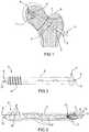
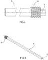
figure 1 is a perspective view of a device for selective biological synthesis of a bone tissue in the insertion site;figure 2 is a lateral view of a component of the device for selective biological synthesis of a bone tissue according tofigure 1 ;figure 3 is a sectional lateral view of some components of the device for selective biological synthesis of a bone tissue according tofigures 1 and 2 ,figure 4 is an interrupted lateral view of a further component of the device for selective biological synthesis of a bone tissue according to the present invention;figure 5 is a perspective view of the further component of the device for selective biological synthesis of a bone tissue according tofigure 4 ;figure 6 is a top view of the device for selective biological synthesis of a bone tissue completely assembled according to the present invention;figure 7 is an enlarged view of a detail offigure 6 .- With reference to the figures, a device for selective biological synthesis of a bone tissue according to the present invention is indicated with 1. Such device is biocompatible with the tissue into which it is inserted.
- The
device 1 comprises ascrew 2 for the stabilisation of a fracture or of a osteoporotic bone tissue, provided with a longitudinal axis X and comprising an extendedbody 3 which externally has athreading 4. Such threading 4 is substantially arranged at the front part of thescrew 2.- The
extended body 3 internally comprises alongitudinal channel 5. Thelongitudinal channel 5 and theextended body 3 are also arranged along the axis X of thescrew 2. - The
screw 2 has, at the front part thereof, a first end ortip 6, substantially tapered and/or with a suitable shape capable of allowing the insertion thereof into the soft tissue, first, and bone tissue, then, of the patient. The first end ortip 6 has, as observable infigures 2 and 3 , agroove 12 which allows a better insertion of thescrew 2 into the tissues which it should traverse. - The
screw 2 also has a second end orhead 7, also traversed by thelongitudinal channel 5. - The
longitudinal channel 5 traverses at least the extendedbody 3 and the second end orhead 7 of thescrew 2; the first end ortip 6 of thescrew 2 can be traversed or not traversed by thelongitudinal channel 5. - The second end or
head 7 has a coupling element, for example hexagonal shaped or generally of any suitable shape, capable of allowing the coupling of thescrew 2 using an insertion tool, as explained hereinafter. The coupling element can be positioned in a seat recessed or projecting with respect to the second end orhead 7 of thescrew 2. - The
screw 2 can be in form of a pin or any other means suitable for the purpose and it has a cylindrical section, prismatic section or any other shape capable of allowing the insertion thereof into the human body. - The
device 1 is adapted to be coupled with an injection system S, illustrated infigure 6 , through coupling means A of the known type and through aninjector 11, as explained hereinafter in the present description. Through the injection system S and thedevice 1 there occurs the injection, in the site of interest, of bone cement, for example containing polymethylmethacrylate, and/or of regenerative factors, for example stem cells, growth factors, platelet gel, etcetera, and/or of other antibiotic or medicinal substances, etcetera, so as to stabilise, cure and possibly regenerate, the fractures of the patients who have suffered a trauma or osteoporotic patients. - The
screws 2 are available in various dimensions, with a diameter between 6 mm to 12 mm and a length from 70 mm to 120 mm. For example, the main dimensions of thescrew 2 are: diameter of 8.5 mm or 10 mm, length of 80 mm, 90 mm, 100 mm a according to the anatomic needs of the patient into whom they are to be inserted. Advantageously, the previously mentioned dimensions allow providing a device for selective biological synthesis of a bone tissue that is less invasive to conserve the bone tissue and, simultaneously, mechanically suitable for the purpose. - Actually, the aforementioned dimensions were reduced with respect to the known devices, to guarantee the introduction through percutaneous access of the
device 1. However, other dimensions can be used, without departing from the scope of protection of the present invention. - As observable in
figure 1 , theextended body 3 has an outer surface substantially smooth in proximity of the fracture line F. - The absence of the
threading 4 in this area allows the development of micro-movements and facilitates the correct formation of the bone callus during the after operation period. - As observable in
figures 1-3 , thescrew 2 has, in theextended body 3 thereof, a series of through holes orslots 9, in communication with thelongitudinal channel 5 and arranged so as to allow the selective injection of the bone cement and/or the aforementioned substances through the desired holes orslots 9. In particular, the holes orslots 9 comprise various shapes, positions and dimensions, so as to allow a "targeted" introduction of the aforementioned substances into the required and/or desired positions, as specified hereinafter. Actually, a further object of the present invention is to provide a device for selective biological synthesis of a bone tissue capable of allowing the accurate introduction of fluids so as to direct them into the site of greater need/use. - In a particular embodiment, illustrated in
figures 3 and6-7 , the holes orslots 9 comprise: circular holes 9', arranged between the turns of thethreading 4 and adapted to guarantee a homogeneous distribution of the substances, and elliptic holes 9'', arranged in polar position alternated at 360° along the extendedbody 3 and adapted to guarantee high flow rate. - In particular, the circular holes 9' do not have an identical position along the axis X of the
screw 2 but they have a helical development, given that they follow the development of thethreading 4. They are small in dimension but approached with respect to each other, so as to guarantee the required capacity and diffusion of the previously indicated substances. - The elliptic holes 9'', instead have larger dimensions with respect to those of the circular holes 9', and thus greater flow rate. The elliptic shape is conferred to prevent possible weakening of the structure of the
screw 2, which could be created, for example, by circular holes of the same flow rate as the elliptic holes 9''. - The
holes 9 are arranged substantially along the entire surface of the extendedbody 3 of thescrew 2, so as to have the possibility of performing, through thescrew 2, selective injection of the previously mentioned substances at any desired or required position. - However, such positions and arrangement of the holes or
slots 9 represent an exemplifying but non-limiting characteristic of the present invention. - As observable in
figures 4 and 5 , the device for selective biological synthesis of a bone tissue further comprises apin 8, having a substantially extended configuration and parallel to the axis X of thescrew 2, adapted to guarantee greater resistance of the implant. - The
pin 8 has a first distal end, arranged at the first end ortip 6 of thescrew 2, and a second proximal end, arranged at the second end orhead 7 of thescrew 2. - The
pin 8 has a length substantially equivalent to that of thelongitudinal channel 5. - The
pin 8 is inserted into thelongitudinal channel 5 of thescrew 2, at the end of the injection of the previously indicated substances, by means of a special insertion tool, possibly in form of a screwdriver. The insertion of thepin 8 in thelongitudinal channel 5 determines the emptying of the latter of the bone cement and/or of the injected substances. This allows obtaining an accurate measurement of the amount of cement and/or injected substances given that the amount measured by the injection system S corresponds to that actually injected into the insertion site of thescrew 2. Furthermore, the emptying of thelongitudinal channel 5 by thepin 8 allows making the channel available for possible further injection of substances or for the subsequent prescribed surgical operation. - The diameter of the
pin 8 is slightly smaller than the diameter of thelongitudinal channel 5 into which it is inserted but such to allow closure thereof. - Due to the bending forces, the outer screw deforms and the two ends of the screw rest on the
inner pin 8 and thus, though thepin 8 is not completely integrated in the tubular region, it however contributes to the resistance of thedevice 1. - In particular the
pin 8 has a snap-fitting constraint in the proximal end thereof, at the releasable connection means, as better described hereinafter, and a slidable support in the other distal end. - The
pin 8 is made of titanium or the alloys thereof. The resistance thus obtained is greater than any cannulated screw present in the prior art. - Actually, the introduction of the
pin 8 guarantees the closure of thescrew 2 and further reinforces the resistance of thedevice 1, transforming a cannulated section, such as thescrew 2, into a solid section, provided by thespin 8 inserted into thescrew 2, and partly eliminating the effects of the groove given by the presence of holes orslots 9. - The
pin 8 can be inserted and/or screwed into thelongitudinal channel 5 and there are provided releasable connection means for such purpose. - Such releasable connection means are arranged at the proximal end thereof or at any other point of the
pin 8 suitable for the purpose. Such releasable connection means allow thepin 8 to be reversibly connected to thescrew 2, due to the presence on the latter, of corresponding releasable means positioned in proximity of the second end orhead 7 of thescrew 2 or however at said releasable connection means of thepin 8. - The releasable connection means, in a first embodiment, are constituted by a threading 10, present at the proximal end of the pin, and, as observable in
figure 3 , by afemale screw 13 positioned at the second end orhead 7 of thescrew 2, into which there is screwed the threading 10 of thepin 8. - In a further embodiment, the releasable connection means may acquire a bayonet configuration or any other known type of reversible coupling.
- The
pin 8 has a section corresponding to the section of thelongitudinal channel 5 of thescrew 2 into which it is inserted. - The technique that can be used for the plant of the
device 1 comprises the following steps: inserting a guide wire, preparing the intervention seat on the cortical part of the bone by mounting a mill on the guide wire, extracting the mill and reducing the fracture. - Subsequently, the implant technique provides for the following steps: mounting a measuring device on the guide wire, so as to identify the correct length of the
screw 2. Then thescrew 2 is mounted on a special first insertion tool, for example a screwdriver or other tools suitable for the purpose, mounting the first insertion tool and thescrew 2 on the guide wire and the ensuing screwing thereof, by rotating the insertion tool. - Such insertion tool has a handle, a hollow rod C, adapted to allow the passage of the guide wire therein and other devices and/or accessories required in the subsequent steps of the implant, and a tip complementary to the coupling element present in the second end or
head 7 of thescrew 2, so as to allow screwing thereof. - Upon inserting and/or screwing the
screw 2, the guide wire is extracted, just like the handle of the first insertion tool. The rod C of the first insertion tool, is instead left in the seat for a subsequent use thereof. - In a subsequent step there occurs the preparation and mounting the injection system S, possibly in form of a syringe, into which there are inserted the previously indicated substances such as: bone cement and/or regenerative factors and/or stem cells and/or growth factors and/or platelet gel and/or other antibiotic or medicinal substances, etcetera.
- The
device 1 further comprises aninjector 11, of the cannulated type, comprising a lower end, adapted to be coupled with the injection system S, possibly by means of an adapter A of the known type, and an upper end, through which the aforementioned substances are injected, adapted to be inserted into thelongitudinal channel 5 of thescrew 2. - The
injector 11 allows obtaining a selective injection of the abovementioned substances through the required/desired holes orslots 9 and/or through the first end ortip 6 of thescrew 2. Such injector 11 is inserted into thelongitudinal channel 5 of thescrew 2;such injector 11 may be completely inserted into thelongitudinal channel 5 of thescrew 2, allowing reaching the portions of thescrew 2 corresponding to the first end or tip thereof. This allows bringing the material or the substances that should be inserted into thescrew 2 in proximity of the desired points, preventing the substance or the material that should be injected through thescrew 2, being in fluid state, from being dispersed in undesired and non-required points.- In a first embodiment, the insertion of the
injector 11 into thelongitudinal channel 5 allows reaching, and thus spreading, first the distal part of thescrew 2, at the end ortip 6 thereof, and then the cylindrical holes 9', that would be otherwise difficult to reach by the substances introduced into thescrew 2, and secondly the elliptic holes 9''. - In a further embodiment, the possibility of inserting the
injector 11 intolongitudinal channel 5 allows reaching given andspecific holes 9 and thus performing a selective injection solely in some holes or performing injection of determined substances in some holes and other substances in other holes, depending on the needs of the patient. In particular, in an exemplifying and non-limiting embodiment, it would be possible to perfuse with bone cement the holes corresponding to theends screw 2, with the aim of anchoring them into the insertion site. It would thus be possible perfuse with regenerative substances or substances of any other type the holes at the fracture line where, in some cases, it would be advisable to avoid perfusion of the bone cement and where instead it is possible to introduce regenerative substances, with the aim of promoting bone regeneration and the ensuing consolidation of the fracture. Also other injection variants can be provided for, depending on the therapeutic approach and the conditions of the patient. - The selective injection described above is carried out in an accurate and efficient manner given that the
injector 11 has a series of graduatedreferences 14, which allow alignment thereof with the base of the first insertion tool and then with thetip 6 of thescrew 2. Such references allow identifying and reaching the desired or required holes orslots 9. After inserting theinjector 11 on the previously filled injection system and before inserting theinjector 11 into the rod C of the insertion tool, there follows the filling of the injector with the substances contained in the injection system S. - At the upper end of the
injector 11 there is inserted, possibly, a protection against the reflux (not illustrated) which prevents the insertion and the raising of the biological fluid or any other type of fluid in theinjector 11. - Upon inserting the
injector 11 into the rod C of the insertion tool, there occurs the alignment of the graduatedreferences 14 of theinjector 11, and hence of the upper end thereof with the base of the insertion tool, so as to identify and select the position of the various holes orslots 9 to be subjected to perfusion, depending on the depth intended to be reached with the upper end of the injector or the operation strategy being followed. Obtaining homogeneous injection along the entireextended body 3 of thescrew 2 requires starting the injection from the distal part of thescrew 2, at the first end ortip 6 thereof. - Upon terminating the injection in the desired points, the implantation technique provides for detaching the injection system S from the
injector 11, still in the site, and inserting, into the injector, an emptying device (not illustrated), so as to entirely empty the body of theinjector 11 and prevent the loss of bone cement and/or regenerative factors and/or other substances in the soft tissues or in the rod C of the first insertion tool. - The emptying device is in form of a plunger or pin or any other form suitable for the purpose.
- Upon extracting the
injector 11 alongside the emptying device, thepin 8 is mounted in a special second insertion tool and the entirety is inserted into the first insertion tool left in the seat. Thepin 8 is inserted and/or screwed by rotating the second insertion tool coupling the releasable coupling means arranged at the proximal end of the pin and the second end orhead 7 of thescrew 2. - Once the
pin 8 is inserted and/or screwed, there are extracted the first and the second insertion tool. Due to the insertion of thepin 8, thescrew 2 is left clear of bone cement residues and/or other substances and this allows - during check-up - to remove thepin 8 and perform new injection operations if required or periodical therapeutic strategy check-ups through repeatable, selective and minimally traumatic surgical operations. Thescrew 2 thus has a releasable closure by thepin 8. - Thus, the presence of the
pin 8 which clears thelongitudinal channel 5 and the releasable connection means, allows obtaining an injection of the substances indicated above deferred over time, besides being selective. - During the intervention it is advisable to implant at least two screws with parallel direction, one upper and one lower, with a distance of about 17 mm from each other, to improve the overall resistance of the
device 1 on the bone and to prevent, in the absence of the second screw, the rotation of the detached bone segment on the axis of the first. - The present invention further comprises a surgical and therapeutic method, which however is not claimed, for selective biological synthesis of a bone tissue, the stabilisation of bone fractures, the spread, in the bone tissue, of biological substances and/or bone cement useful for the primary stabilisation and/or regeneration of the bone tissue, according the steps of providing the
screw 2, providing an injection system S for the injection of the bone cement and/or regenerative factors and/or stem cells and/or growth factors and/or platelet gel and/or other antibiotic or medicinal substances, providing aninjector 11, comprising a lower end, adapted to be coupled with the injection system S, and an upper end, through which the aforementioned substances are injected, adapted to be inserted into thelongitudinal channel 5 of thescrew 2, by inserting theinjector 11 into thelongitudinal channel 5. - The method according to the invention, which however is not claimed, comprises a further step of aligning the
injector 11, through a series of graduatedreferences 14 present thereof, with the first end ortip 6 of thescrew 2. Furthermore, there are provided the steps of displacing, slidably, the proximal end of theinjector 11 to align it with the selected holes orslots 9, for injecting the aforementioned substances through thescrew 2 and/or selectedholes 9. - The method according to the invention, which however is no claimed, further comprises the steps of extracting the
injector 11, providing apin 8, inserting thepin 8 into thelongitudinal channel 5, reversibly fastening thescrew 2 through releasable connection means provided for on thepin 8 with ensuing emptying of thelongitudinal channel 5. - Regarding the method according to the present invention, which is not claimed, there are further steps of disconnecting the
pin 8 from thescrew 2, repeating the step of injecting the aforementioned substances by means of theinjector 11, through thescrew 2 and/orholes 9, reinserting, after removing theinjector 11, thepin 8 releasably. - The present invention as conceived can be subjected to various modifications and variants all falling within the scope of protection of the claims.
Claims (18)
- Device (1) for selective biological synthesis of a bone tissue comprising a screw (2) for the stabilisation of a fracture or of an osteoporotic bone tissue, wherein said screw (2) is arranged along an axis (X), substantially longitudinal with respect to said screw (2) itself, and it is constituted by an extended body (3), from a first end or tip (6) and from a second end or head (7), wherein at least said extended body (2) and said second end or head (7) comprise a longitudinal channel (5), wherein said extended body (3) has at least one hole or slot (9, 9', 9''), said device further comprising a pin (8), insertable into said longitudinal channel (5) and provided with releasable connection means with said screw (2), for reinforcing the device (1) and for the releasable closure of said screw (2),characterised in that said device (1) comprises an injector (11) of the cannulated type, comprising a lower end, suitable to be coupled with an injection system (S) by means of an adapter (A), and an upper end, suitable to be completely inserted into said longitudinal channel (5) of said screw (2) so as to obtain a selective injection through said holes or slots (9, 9', 9'') and/or said first end or tip (6) and wherein said upper end of said injector (11) is inserted into said longitudinal channel (5) of said screw (2) at a position selectable depending on the position of the screw (2) intended to be reached or of said holes or slots (9, 9', 9'') to be subjected to perfusion.
- Device (1) according to claim 1, wherein said pin (8) has a substantially extended configuration, parallel to the axis (X) of said screw (2), and it has a first distal end, arranged at said first end or tip (6) of said screw (2), and a second proximal end, arranged at said second end or head (7) of said screw (2).
- Device (1) according to claim 1 or 2, wherein said pin (8) has a diameter slightly smaller than the diameter of said longitudinal channel (5) and/or a length substantially equivalent to that of said longitudinal channel (5).
- Device (1) according to one of the preceding claims, wherein said pin (8) is suitable to be inserted into said longitudinal channel (5) by screwing.
- Device (1) according to one of the preceding claims, wherein said pin (8) is made of titanium or alloys thereof.
- Device (1) according to one of the preceding claims, wherein said releasable connection means are arranged at said proximal end of said pin (8).
- Device (1) according to one of the preceding claims, wherein said releasable connection means comprise a threading (10), present on said pin (8), and a female screw (13) positioned at said second end or head (7) or connection means of bayonet configuration or any other known type of reversible coupling.
- Device (1) according to one of the preceding claims, wherein said reinforcing made by said pin (8) gives a greater resistance to said device (1).
- Device (1) according to one of the preceding claims, wherein said pin (8) has a snap-fitting constraint in the proximal end thereof, at said releasable connection means, and a slidable support in the other distal end.
- Device (1) according to claim 1, wherein said screw (2) has a threading (4) positioned substantially at said first end or tip (6) of said screw (2).
- Device (1) according to claim 1, wherein said first end or tip (6) is substantially tapered and/or has a shape suitable to allow the insertion of said screw (2) into the body of a patient.
- Device (1) according to one of the preceding claims, wherein said screw (2) is configured to form a nail or any other means suitable for the purpose and has a cylindrical section, prismatic section or any other section capable of facilitating insertion thereof into the body of a patient.
- Device (1) according to claim 1, wherein said lower end is suitable to be inserted into said injection system (S) through adaptor means (A).
- Device (1) according to claim 1, wherein said injector (11) has one or more graduated references (14) suitable to refer the upper end of the injector (11) with said holes or slots (9, 9', 9'') and/or with said first end or tip (6) of said screw (2).
- Device (1) according to claim 1, wherein said injector (11) comprises an anti-reflux protection, positionable on said upper end of said injector (11) and/or an emptying device, in form of a plunger or pin, for emptying said injector (11).
- Device (1) according to claims 1, wherein said device allows injection into the concerned site, through said injector (11) and said system (S) for injecting bone cement and/or regenerative factors and/or stem cells and/or growth factors and/or platelet gel and/or other antibiotic or medicinal substances.
- Device (1) according to claim 1, wherein said holes or slots (9, 9', 9'') comprise holes of various shapes, positions and sizes, so as to allow "targeted" introduction of said bone cement and/or regenerative factors and/or stem cells and/or growth factors and/or platelet gel and/or other antibiotic or medicinal substances, into the required and/or desired positions.
- Device (1) according to claim 1, wherein said holes or slots (9, 9', 9'') comprise circular holes (9') arranged between the turns of said threading (4) and/or elliptic holes (9'') arranged along said extended body (3) of said screw (2).
Applications Claiming Priority (2)
| Application Number | Priority Date | Filing Date | Title |
|---|---|---|---|
| ITVR2010A000121AIT1401021B1 (en) | 2010-06-15 | 2010-06-15 | DEVICE FOR THE SELECTIVE BIOLOGICAL SYNTHESIS OF A BONE FABRIC |
| PCT/IB2011/052603WO2011158193A1 (en) | 2010-06-15 | 2011-06-15 | Device for selective biological synthesis of a bone tissue |
Publications (2)
| Publication Number | Publication Date |
|---|---|
| EP2582312A1 EP2582312A1 (en) | 2013-04-24 |
| EP2582312B1true EP2582312B1 (en) | 2017-08-09 |
Family
ID=43428615
Family Applications (1)
| Application Number | Title | Priority Date | Filing Date |
|---|---|---|---|
| EP11738294.5ANot-in-forceEP2582312B1 (en) | 2010-06-15 | 2011-06-15 | Device for selective biological synthesis of a bone tissue |
Country Status (5)
| Country | Link |
|---|---|
| US (1) | US9504505B2 (en) |
| EP (1) | EP2582312B1 (en) |
| ES (1) | ES2649400T3 (en) |
| IT (1) | IT1401021B1 (en) |
| WO (1) | WO2011158193A1 (en) |
Cited By (2)
| Publication number | Priority date | Publication date | Assignee | Title |
|---|---|---|---|---|
| IT202000020551A1 (en) | 2020-08-27 | 2022-02-27 | Rinaldo Giancola | DEVICE FOR THE SELECTIVE BIOLOGICAL SYNTHESIS OF A BONE TISSUE |
| US11986222B2 (en) | 2021-12-20 | 2024-05-21 | Rinaldo Giancola | Device for the selective biological synthesis of a bone tissue |
Families Citing this family (20)
| Publication number | Priority date | Publication date | Assignee | Title |
|---|---|---|---|---|
| WO2013030835A1 (en)* | 2011-08-29 | 2013-03-07 | David Regev | Dental implant system and methods for accessing intra cavity areas therethrough |
| US20130211466A1 (en)* | 2012-02-15 | 2013-08-15 | Warsaw Orthopedic, Inc. | Bone fastener and methods of use |
| US20130317555A1 (en)* | 2012-05-22 | 2013-11-28 | Benvenue Medical, Inc. | Implant and system for bone repair |
| US10179014B1 (en)* | 2012-06-01 | 2019-01-15 | Nuvasive, Inc. | Systems and methods for promoting sacroiliac joint fusion |
| US9295488B2 (en)* | 2012-08-09 | 2016-03-29 | Wilson T. Asfora | Joint fusion |
| US9993276B2 (en)* | 2013-03-15 | 2018-06-12 | Innovision, Inc. | Bone screws and methods of use thereof |
| WO2017213893A1 (en)* | 2016-06-08 | 2017-12-14 | Smith & Nephew, Inc. | Suture anchor assembly for delivery of a therapeutic agent |
| US9655661B1 (en)* | 2016-06-30 | 2017-05-23 | Hugh Boyd Watts | Cannulated orthopedic screw and method of reducing and fixing a fracture of the lateral malleolus |
| FR3054787B1 (en)* | 2016-08-05 | 2021-12-10 | Spine Arch Brevet | CURVED ANCHOR FOR FIXING BONE ELEMENTS |
| KR101850831B1 (en)* | 2016-10-28 | 2018-06-12 | 주식회사 휴벡셀 | Pedicle screw using bone cement |
| US10667923B2 (en) | 2016-10-31 | 2020-06-02 | Warsaw Orthopedic, Inc. | Sacro-iliac joint implant system and method |
| RU194230U1 (en)* | 2019-02-06 | 2019-12-03 | федеральное государственное бюджетное образовательное учреждение высшего образования "Самарский государственный аграрный университет" | Multifunctional immersion pin for transosseous osteosynthesis |
| US11660134B2 (en)* | 2019-06-13 | 2023-05-30 | Medos International Sarl | Instruments and methods for delivering bone cement to a bone screw |
| US11564812B2 (en) | 2019-09-09 | 2023-01-31 | Warsaw Orthopedic, Inc. | Surgical instrument and method |
| US11344354B2 (en) | 2019-09-09 | 2022-05-31 | Warsaw Orthopedic, Inc. | Surgical instrument and method |
| US11213332B2 (en)* | 2019-09-17 | 2022-01-04 | DePuy Synthes Products, Inc. | Bone fixation element |
| USD958326S1 (en)* | 2020-05-21 | 2022-07-19 | Spinal Generations, Llc | Intraosseous needle |
| DE102020003320A1 (en) | 2020-06-03 | 2021-12-09 | MIMEO MEDlCAL GmbH | Bone anchor for optimized cement application |
| US11318026B2 (en)* | 2020-07-24 | 2022-05-03 | Synaptic Innovations, LLC | Implant having enhanced initial fixation force |
| EP4124356A1 (en)* | 2021-07-28 | 2023-02-01 | Heraeus Medical GmbH | Device and method for application of a pharmaceutical fluid |
Citations (1)
| Publication number | Priority date | Publication date | Assignee | Title |
|---|---|---|---|---|
| DE20317120U1 (en)* | 2003-11-07 | 2004-04-08 | Schreiber, Ulrich, Dipl.-Ing. | Bone screw, and especially a pedicle screw, has an opening to take an inserted wire with a fastener to secure a stiffener inserted into the opening at least partially |
Family Cites Families (10)
| Publication number | Priority date | Publication date | Assignee | Title |
|---|---|---|---|---|
| US6048343A (en)* | 1999-06-02 | 2000-04-11 | Mathis; John M. | Bone screw system |
| DE19949285C2 (en)* | 1999-10-12 | 2002-08-14 | Impag Gmbh Medizintechnik | bone screw |
| US7608097B2 (en)* | 2003-04-29 | 2009-10-27 | Millennium Medical Technologies | Bone screw with fluid delivery structure |
| US20070299450A1 (en)* | 2004-12-31 | 2007-12-27 | Ji-Hoon Her | Pedicle Screw and Device for Injecting Bone Cement into Bone |
| US20070055257A1 (en)* | 2005-06-30 | 2007-03-08 | Alex Vaccaro | Cannulated screw access system |
| US20070233123A1 (en)* | 2006-02-21 | 2007-10-04 | Osteomed, L.P. | Bone fixation device |
| WO2007106774A2 (en)* | 2006-03-13 | 2007-09-20 | The Johns Hopkins University | Orthopedic screw system |
| WO2008124533A1 (en)* | 2007-04-03 | 2008-10-16 | Dfine, Inc. | Bone treatment systems and methods |
| ITRM20070590A1 (en) | 2007-11-13 | 2009-05-14 | 2B1 S R L | SCREW FOR STABILIZATION OF A BONE FRACTURE AND RELATIVE KIT. |
| US8974505B2 (en)* | 2008-06-16 | 2015-03-10 | Anna G. U. Sawa | Venting/pressure adjustment to aid in delivery of material into an anatomic region via a cannula |
- 2010
- 2010-06-15ITITVR2010A000121Apatent/IT1401021B1/enactive
- 2011
- 2011-06-15EPEP11738294.5Apatent/EP2582312B1/ennot_activeNot-in-force
- 2011-06-15USUS13/704,469patent/US9504505B2/enactiveActive
- 2011-06-15ESES11738294.5Tpatent/ES2649400T3/enactiveActive
- 2011-06-15WOPCT/IB2011/052603patent/WO2011158193A1/enactiveApplication Filing
Patent Citations (1)
| Publication number | Priority date | Publication date | Assignee | Title |
|---|---|---|---|---|
| DE20317120U1 (en)* | 2003-11-07 | 2004-04-08 | Schreiber, Ulrich, Dipl.-Ing. | Bone screw, and especially a pedicle screw, has an opening to take an inserted wire with a fastener to secure a stiffener inserted into the opening at least partially |
Cited By (3)
| Publication number | Priority date | Publication date | Assignee | Title |
|---|---|---|---|---|
| IT202000020551A1 (en) | 2020-08-27 | 2022-02-27 | Rinaldo Giancola | DEVICE FOR THE SELECTIVE BIOLOGICAL SYNTHESIS OF A BONE TISSUE |
| EP3960103A1 (en) | 2020-08-27 | 2022-03-02 | Giancola Rinaldo | Device for the selective biological synthesis of a bone tissue |
| US11986222B2 (en) | 2021-12-20 | 2024-05-21 | Rinaldo Giancola | Device for the selective biological synthesis of a bone tissue |
Also Published As
| Publication number | Publication date |
|---|---|
| ES2649400T3 (en) | 2018-01-11 |
| US9504505B2 (en) | 2016-11-29 |
| ITVR20100121A1 (en) | 2011-12-16 |
| IT1401021B1 (en) | 2013-07-05 |
| WO2011158193A1 (en) | 2011-12-22 |
| EP2582312A1 (en) | 2013-04-24 |
| US20130144344A1 (en) | 2013-06-06 |
Similar Documents
| Publication | Publication Date | Title |
|---|---|---|
| EP2582312B1 (en) | Device for selective biological synthesis of a bone tissue | |
| CN101720207B (en) | Devices, systems and methods for delivering orthotic material into bone | |
| US10682150B2 (en) | Tools for performing less invasive orthopedic joint procedures | |
| US9687285B2 (en) | Fenestrated bone screws and methods of bone fastening and stabilization | |
| US8303598B2 (en) | Fenestrated bone tap and method | |
| AU2009239515B2 (en) | Posterior spinal fastener | |
| EP1787592B1 (en) | Device and system for delivering a curable material into bone | |
| EP2699181B1 (en) | Cannula and kit for evaluation and preparation of bone tissue | |
| US20130072984A1 (en) | Fenestrated bone screws and methods of bone fastening and stabilization | |
| BRPI0718511A2 (en) | CURTABLE MATERIAL DISTRIBUTION DEVICE WITH A TURNTABLE SUPPLY SECTION | |
| US20110040337A1 (en) | Screw for stabilizing a bone fracture and related kit | |
| US20210315619A1 (en) | Osseous anchoring implant with optimized expansion | |
| US11986222B2 (en) | Device for the selective biological synthesis of a bone tissue | |
| EP3960103B1 (en) | Device for the selective biological synthesis of a bone tissue |
Legal Events
| Date | Code | Title | Description |
|---|---|---|---|
| PUAI | Public reference made under article 153(3) epc to a published international application that has entered the european phase | Free format text:ORIGINAL CODE: 0009012 | |
| 17P | Request for examination filed | Effective date:20121212 | |
| AK | Designated contracting states | Kind code of ref document:A1 Designated state(s):AL AT BE BG CH CY CZ DE DK EE ES FI FR GB GR HR HU IE IS IT LI LT LU LV MC MK MT NL NO PL PT RO RS SE SI SK SM TR | |
| DAX | Request for extension of the european patent (deleted) | ||
| 17Q | First examination report despatched | Effective date:20150513 | |
| RAP1 | Party data changed (applicant data changed or rights of an application transferred) | Owner name:4ELDER S.R.L. | |
| RIN1 | Information on inventor provided before grant (corrected) | Inventor name:GIANCOLA, RINALDO | |
| REG | Reference to a national code | Ref country code:DE Ref legal event code:R079 Ref document number:602011040403 Country of ref document:DE Free format text:PREVIOUS MAIN CLASS: A61B0017860000 Ipc:A61B0017700000 | |
| GRAP | Despatch of communication of intention to grant a patent | Free format text:ORIGINAL CODE: EPIDOSNIGR1 | |
| RIC1 | Information provided on ipc code assigned before grant | Ipc:A61B 17/88 20060101ALI20160913BHEP Ipc:A61B 17/70 20060101AFI20160913BHEP Ipc:A61B 17/86 20060101ALI20160913BHEP Ipc:A61B 17/74 20060101ALI20160913BHEP | |
| INTG | Intention to grant announced | Effective date:20161007 | |
| GRAJ | Information related to disapproval of communication of intention to grant by the applicant or resumption of examination proceedings by the epo deleted | Free format text:ORIGINAL CODE: EPIDOSDIGR1 | |
| INTC | Intention to grant announced (deleted) | ||
| GRAS | Grant fee paid | Free format text:ORIGINAL CODE: EPIDOSNIGR3 | |
| GRAP | Despatch of communication of intention to grant a patent | Free format text:ORIGINAL CODE: EPIDOSNIGR1 | |
| INTG | Intention to grant announced | Effective date:20170403 | |
| GRAA | (expected) grant | Free format text:ORIGINAL CODE: 0009210 | |
| AK | Designated contracting states | Kind code of ref document:B1 Designated state(s):AL AT BE BG CH CY CZ DE DK EE ES FI FR GB GR HR HU IE IS IT LI LT LU LV MC MK MT NL NO PL PT RO RS SE SI SK SM TR | |
| REG | Reference to a national code | Ref country code:GB Ref legal event code:FG4D | |
| REG | Reference to a national code | Ref country code:CH Ref legal event code:EP Ref country code:AT Ref legal event code:REF Ref document number:915948 Country of ref document:AT Kind code of ref document:T Effective date:20170815 | |
| REG | Reference to a national code | Ref country code:IE Ref legal event code:FG4D | |
| REG | Reference to a national code | Ref country code:DE Ref legal event code:R096 Ref document number:602011040403 Country of ref document:DE | |
| RAP2 | Party data changed (patent owner data changed or rights of a patent transferred) | Owner name:4ELDER S.R.L. | |
| RAP2 | Party data changed (patent owner data changed or rights of a patent transferred) | Owner name:INTRABONE, INC. | |
| REG | Reference to a national code | Ref country code:SE Ref legal event code:TRGR | |
| REG | Reference to a national code | Ref country code:NL Ref legal event code:MP Effective date:20170809 | |
| REG | Reference to a national code | Ref country code:LT Ref legal event code:MG4D | |
| REG | Reference to a national code | Ref country code:ES Ref legal event code:FG2A Ref document number:2649400 Country of ref document:ES Kind code of ref document:T3 Effective date:20180111 | |
| REG | Reference to a national code | Ref country code:AT Ref legal event code:MK05 Ref document number:915948 Country of ref document:AT Kind code of ref document:T Effective date:20170809 | |
| PG25 | Lapsed in a contracting state [announced via postgrant information from national office to epo] | Ref country code:FI Free format text:LAPSE BECAUSE OF FAILURE TO SUBMIT A TRANSLATION OF THE DESCRIPTION OR TO PAY THE FEE WITHIN THE PRESCRIBED TIME-LIMIT Effective date:20170809 Ref country code:LT Free format text:LAPSE BECAUSE OF FAILURE TO SUBMIT A TRANSLATION OF THE DESCRIPTION OR TO PAY THE FEE WITHIN THE PRESCRIBED TIME-LIMIT Effective date:20170809 Ref country code:NO Free format text:LAPSE BECAUSE OF FAILURE TO SUBMIT A TRANSLATION OF THE DESCRIPTION OR TO PAY THE FEE WITHIN THE PRESCRIBED TIME-LIMIT Effective date:20171109 Ref country code:HR Free format text:LAPSE BECAUSE OF FAILURE TO SUBMIT A TRANSLATION OF THE DESCRIPTION OR TO PAY THE FEE WITHIN THE PRESCRIBED TIME-LIMIT Effective date:20170809 Ref country code:AT Free format text:LAPSE BECAUSE OF FAILURE TO SUBMIT A TRANSLATION OF THE DESCRIPTION OR TO PAY THE FEE WITHIN THE PRESCRIBED TIME-LIMIT Effective date:20170809 Ref country code:NL Free format text:LAPSE BECAUSE OF FAILURE TO SUBMIT A TRANSLATION OF THE DESCRIPTION OR TO PAY THE FEE WITHIN THE PRESCRIBED TIME-LIMIT Effective date:20170809 | |
| PG25 | Lapsed in a contracting state [announced via postgrant information from national office to epo] | Ref country code:IS Free format text:LAPSE BECAUSE OF FAILURE TO SUBMIT A TRANSLATION OF THE DESCRIPTION OR TO PAY THE FEE WITHIN THE PRESCRIBED TIME-LIMIT Effective date:20171209 Ref country code:GR Free format text:LAPSE BECAUSE OF FAILURE TO SUBMIT A TRANSLATION OF THE DESCRIPTION OR TO PAY THE FEE WITHIN THE PRESCRIBED TIME-LIMIT Effective date:20171110 Ref country code:LV Free format text:LAPSE BECAUSE OF FAILURE TO SUBMIT A TRANSLATION OF THE DESCRIPTION OR TO PAY THE FEE WITHIN THE PRESCRIBED TIME-LIMIT Effective date:20170809 Ref country code:BG Free format text:LAPSE BECAUSE OF FAILURE TO SUBMIT A TRANSLATION OF THE DESCRIPTION OR TO PAY THE FEE WITHIN THE PRESCRIBED TIME-LIMIT Effective date:20171109 Ref country code:RS Free format text:LAPSE BECAUSE OF FAILURE TO SUBMIT A TRANSLATION OF THE DESCRIPTION OR TO PAY THE FEE WITHIN THE PRESCRIBED TIME-LIMIT Effective date:20170809 Ref country code:PL Free format text:LAPSE BECAUSE OF FAILURE TO SUBMIT A TRANSLATION OF THE DESCRIPTION OR TO PAY THE FEE WITHIN THE PRESCRIBED TIME-LIMIT Effective date:20170809 | |
| REG | Reference to a national code | Ref country code:CH Ref legal event code:PUE Owner name:INTRABONE, INC., US Free format text:FORMER OWNER: 4ELDER S.R.L., IT | |
| PG25 | Lapsed in a contracting state [announced via postgrant information from national office to epo] | Ref country code:RO Free format text:LAPSE BECAUSE OF FAILURE TO SUBMIT A TRANSLATION OF THE DESCRIPTION OR TO PAY THE FEE WITHIN THE PRESCRIBED TIME-LIMIT Effective date:20170809 Ref country code:CZ Free format text:LAPSE BECAUSE OF FAILURE TO SUBMIT A TRANSLATION OF THE DESCRIPTION OR TO PAY THE FEE WITHIN THE PRESCRIBED TIME-LIMIT Effective date:20170809 Ref country code:DK Free format text:LAPSE BECAUSE OF FAILURE TO SUBMIT A TRANSLATION OF THE DESCRIPTION OR TO PAY THE FEE WITHIN THE PRESCRIBED TIME-LIMIT Effective date:20170809 | |
| REG | Reference to a national code | Ref country code:DE Ref legal event code:R097 Ref document number:602011040403 Country of ref document:DE | |
| PG25 | Lapsed in a contracting state [announced via postgrant information from national office to epo] | Ref country code:SK Free format text:LAPSE BECAUSE OF FAILURE TO SUBMIT A TRANSLATION OF THE DESCRIPTION OR TO PAY THE FEE WITHIN THE PRESCRIBED TIME-LIMIT Effective date:20170809 Ref country code:SM Free format text:LAPSE BECAUSE OF FAILURE TO SUBMIT A TRANSLATION OF THE DESCRIPTION OR TO PAY THE FEE WITHIN THE PRESCRIBED TIME-LIMIT Effective date:20170809 Ref country code:EE Free format text:LAPSE BECAUSE OF FAILURE TO SUBMIT A TRANSLATION OF THE DESCRIPTION OR TO PAY THE FEE WITHIN THE PRESCRIBED TIME-LIMIT Effective date:20170809 | |
| PLBE | No opposition filed within time limit | Free format text:ORIGINAL CODE: 0009261 | |
| STAA | Information on the status of an ep patent application or granted ep patent | Free format text:STATUS: NO OPPOSITION FILED WITHIN TIME LIMIT | |
| REG | Reference to a national code | Ref country code:FR Ref legal event code:PLFP Year of fee payment:8 | |
| 26N | No opposition filed | Effective date:20180511 | |
| REG | Reference to a national code | Ref country code:GB Ref legal event code:732E Free format text:REGISTERED BETWEEN 20180719 AND 20180725 | |
| REG | Reference to a national code | Ref country code:DE Ref legal event code:R081 Ref document number:602011040403 Country of ref document:DE Owner name:INTRABONE, INC., PEACHTREE CORNERS, US Free format text:FORMER OWNER: 4ELDER S.R.L., MILANO, IT | |
| PG25 | Lapsed in a contracting state [announced via postgrant information from national office to epo] | Ref country code:SI Free format text:LAPSE BECAUSE OF FAILURE TO SUBMIT A TRANSLATION OF THE DESCRIPTION OR TO PAY THE FEE WITHIN THE PRESCRIBED TIME-LIMIT Effective date:20170809 | |
| PGFP | Annual fee paid to national office [announced via postgrant information from national office to epo] | Ref country code:FR Payment date:20180626 Year of fee payment:8 Ref country code:TR Payment date:20180528 Year of fee payment:8 Ref country code:IT Payment date:20180508 Year of fee payment:8 | |
| PGFP | Annual fee paid to national office [announced via postgrant information from national office to epo] | Ref country code:SE Payment date:20180627 Year of fee payment:8 | |
| PGFP | Annual fee paid to national office [announced via postgrant information from national office to epo] | Ref country code:ES Payment date:20180702 Year of fee payment:8 Ref country code:DE Payment date:20180627 Year of fee payment:8 Ref country code:GB Payment date:20180627 Year of fee payment:8 | |
| PGFP | Annual fee paid to national office [announced via postgrant information from national office to epo] | Ref country code:CH Payment date:20180704 Year of fee payment:8 | |
| REG | Reference to a national code | Ref country code:BE Ref legal event code:MM Effective date:20180630 | |
| REG | Reference to a national code | Ref country code:IE Ref legal event code:MM4A | |
| PG25 | Lapsed in a contracting state [announced via postgrant information from national office to epo] | Ref country code:LU Free format text:LAPSE BECAUSE OF NON-PAYMENT OF DUE FEES Effective date:20180615 Ref country code:MC Free format text:LAPSE BECAUSE OF FAILURE TO SUBMIT A TRANSLATION OF THE DESCRIPTION OR TO PAY THE FEE WITHIN THE PRESCRIBED TIME-LIMIT Effective date:20170809 | |
| PG25 | Lapsed in a contracting state [announced via postgrant information from national office to epo] | Ref country code:IE Free format text:LAPSE BECAUSE OF NON-PAYMENT OF DUE FEES Effective date:20180615 | |
| PG25 | Lapsed in a contracting state [announced via postgrant information from national office to epo] | Ref country code:BE Free format text:LAPSE BECAUSE OF NON-PAYMENT OF DUE FEES Effective date:20180630 | |
| REG | Reference to a national code | Ref country code:DE Ref legal event code:R119 Ref document number:602011040403 Country of ref document:DE | |
| REG | Reference to a national code | Ref country code:SE Ref legal event code:EUG | |
| PG25 | Lapsed in a contracting state [announced via postgrant information from national office to epo] | Ref country code:MT Free format text:LAPSE BECAUSE OF NON-PAYMENT OF DUE FEES Effective date:20180615 Ref country code:SE Free format text:LAPSE BECAUSE OF NON-PAYMENT OF DUE FEES Effective date:20190616 | |
| REG | Reference to a national code | Ref country code:CH Ref legal event code:PL | |
| GBPC | Gb: european patent ceased through non-payment of renewal fee | Effective date:20190615 | |
| PG25 | Lapsed in a contracting state [announced via postgrant information from national office to epo] | Ref country code:GB Free format text:LAPSE BECAUSE OF NON-PAYMENT OF DUE FEES Effective date:20190615 Ref country code:DE Free format text:LAPSE BECAUSE OF NON-PAYMENT OF DUE FEES Effective date:20200101 Ref country code:IT Free format text:LAPSE BECAUSE OF NON-PAYMENT OF DUE FEES Effective date:20190615 | |
| PG25 | Lapsed in a contracting state [announced via postgrant information from national office to epo] | Ref country code:PT Free format text:LAPSE BECAUSE OF FAILURE TO SUBMIT A TRANSLATION OF THE DESCRIPTION OR TO PAY THE FEE WITHIN THE PRESCRIBED TIME-LIMIT Effective date:20170809 Ref country code:LI Free format text:LAPSE BECAUSE OF NON-PAYMENT OF DUE FEES Effective date:20190630 Ref country code:HU Free format text:LAPSE BECAUSE OF FAILURE TO SUBMIT A TRANSLATION OF THE DESCRIPTION OR TO PAY THE FEE WITHIN THE PRESCRIBED TIME-LIMIT; INVALID AB INITIO Effective date:20110615 Ref country code:CH Free format text:LAPSE BECAUSE OF NON-PAYMENT OF DUE FEES Effective date:20190630 | |
| PG25 | Lapsed in a contracting state [announced via postgrant information from national office to epo] | Ref country code:FR Free format text:LAPSE BECAUSE OF NON-PAYMENT OF DUE FEES Effective date:20190630 Ref country code:CY Free format text:LAPSE BECAUSE OF FAILURE TO SUBMIT A TRANSLATION OF THE DESCRIPTION OR TO PAY THE FEE WITHIN THE PRESCRIBED TIME-LIMIT Effective date:20170809 Ref country code:MK Free format text:LAPSE BECAUSE OF NON-PAYMENT OF DUE FEES Effective date:20170809 | |
| PG25 | Lapsed in a contracting state [announced via postgrant information from national office to epo] | Ref country code:AL Free format text:LAPSE BECAUSE OF FAILURE TO SUBMIT A TRANSLATION OF THE DESCRIPTION OR TO PAY THE FEE WITHIN THE PRESCRIBED TIME-LIMIT Effective date:20170809 | |
| REG | Reference to a national code | Ref country code:ES Ref legal event code:FD2A Effective date:20201028 | |
| PG25 | Lapsed in a contracting state [announced via postgrant information from national office to epo] | Ref country code:ES Free format text:LAPSE BECAUSE OF NON-PAYMENT OF DUE FEES Effective date:20190616 | |
| PG25 | Lapsed in a contracting state [announced via postgrant information from national office to epo] | Ref country code:TR Free format text:LAPSE BECAUSE OF NON-PAYMENT OF DUE FEES Effective date:20190615 |