EP2582306B1 - Systems and methods for creating arteriovenous (av) fistulas - Google Patents
Systems and methods for creating arteriovenous (av) fistulasDownload PDFInfo
- Publication number
- EP2582306B1 EP2582306B1EP11796369.4AEP11796369AEP2582306B1EP 2582306 B1EP2582306 B1EP 2582306B1EP 11796369 AEP11796369 AEP 11796369AEP 2582306 B1EP2582306 B1EP 2582306B1
- Authority
- EP
- European Patent Office
- Prior art keywords
- vessel
- toggle
- distal end
- needle
- piercing
- Prior art date
- Legal status (The legal status is an assumption and is not a legal conclusion. Google has not performed a legal analysis and makes no representation as to the accuracy of the status listed.)
- Active
Links
Images


Classifications
- A—HUMAN NECESSITIES
- A61—MEDICAL OR VETERINARY SCIENCE; HYGIENE
- A61M—DEVICES FOR INTRODUCING MEDIA INTO, OR ONTO, THE BODY; DEVICES FOR TRANSDUCING BODY MEDIA OR FOR TAKING MEDIA FROM THE BODY; DEVICES FOR PRODUCING OR ENDING SLEEP OR STUPOR
- A61M1/00—Suction or pumping devices for medical purposes; Devices for carrying-off, for treatment of, or for carrying-over, body-liquids; Drainage systems
- A61M1/36—Other treatment of blood in a by-pass of the natural circulatory system, e.g. temperature adaptation, irradiation ; Extra-corporeal blood circuits
- A61M1/3621—Extra-corporeal blood circuits
- A61M1/3653—Interfaces between patient blood circulation and extra-corporal blood circuit
- A61M1/3655—Arterio-venous shunts or fistulae
- A—HUMAN NECESSITIES
- A61—MEDICAL OR VETERINARY SCIENCE; HYGIENE
- A61B—DIAGNOSIS; SURGERY; IDENTIFICATION
- A61B17/00—Surgical instruments, devices or methods
- A61B17/11—Surgical instruments, devices or methods for performing anastomosis; Buttons for anastomosis
- A—HUMAN NECESSITIES
- A61—MEDICAL OR VETERINARY SCIENCE; HYGIENE
- A61B—DIAGNOSIS; SURGERY; IDENTIFICATION
- A61B17/00—Surgical instruments, devices or methods
- A61B17/32—Surgical cutting instruments
- A61B17/320068—Surgical cutting instruments using mechanical vibrations, e.g. ultrasonic
- A—HUMAN NECESSITIES
- A61—MEDICAL OR VETERINARY SCIENCE; HYGIENE
- A61B—DIAGNOSIS; SURGERY; IDENTIFICATION
- A61B17/00—Surgical instruments, devices or methods
- A61B17/34—Trocars; Puncturing needles
- A—HUMAN NECESSITIES
- A61—MEDICAL OR VETERINARY SCIENCE; HYGIENE
- A61B—DIAGNOSIS; SURGERY; IDENTIFICATION
- A61B18/00—Surgical instruments, devices or methods for transferring non-mechanical forms of energy to or from the body
- A61B18/04—Surgical instruments, devices or methods for transferring non-mechanical forms of energy to or from the body by heating
- A61B18/08—Surgical instruments, devices or methods for transferring non-mechanical forms of energy to or from the body by heating by means of electrically-heated probes
- A61B18/082—Probes or electrodes therefor
- A—HUMAN NECESSITIES
- A61—MEDICAL OR VETERINARY SCIENCE; HYGIENE
- A61B—DIAGNOSIS; SURGERY; IDENTIFICATION
- A61B18/00—Surgical instruments, devices or methods for transferring non-mechanical forms of energy to or from the body
- A61B18/04—Surgical instruments, devices or methods for transferring non-mechanical forms of energy to or from the body by heating
- A61B18/12—Surgical instruments, devices or methods for transferring non-mechanical forms of energy to or from the body by heating by passing a current through the tissue to be heated, e.g. high-frequency current
- A61B18/14—Probes or electrodes therefor
- A61B18/1492—Probes or electrodes therefor having a flexible, catheter-like structure, e.g. for heart ablation
- A—HUMAN NECESSITIES
- A61—MEDICAL OR VETERINARY SCIENCE; HYGIENE
- A61B—DIAGNOSIS; SURGERY; IDENTIFICATION
- A61B18/00—Surgical instruments, devices or methods for transferring non-mechanical forms of energy to or from the body
- A61B18/18—Surgical instruments, devices or methods for transferring non-mechanical forms of energy to or from the body by applying electromagnetic radiation, e.g. microwaves
- A—HUMAN NECESSITIES
- A61—MEDICAL OR VETERINARY SCIENCE; HYGIENE
- A61M—DEVICES FOR INTRODUCING MEDIA INTO, OR ONTO, THE BODY; DEVICES FOR TRANSDUCING BODY MEDIA OR FOR TAKING MEDIA FROM THE BODY; DEVICES FOR PRODUCING OR ENDING SLEEP OR STUPOR
- A61M25/00—Catheters; Hollow probes
- A61M25/01—Introducing, guiding, advancing, emplacing or holding catheters
- A61M25/09—Guide wires
- A61M25/09041—Mechanisms for insertion of guide wires
- A—HUMAN NECESSITIES
- A61—MEDICAL OR VETERINARY SCIENCE; HYGIENE
- A61N—ELECTROTHERAPY; MAGNETOTHERAPY; RADIATION THERAPY; ULTRASOUND THERAPY
- A61N7/00—Ultrasound therapy
- A61N7/02—Localised ultrasound hyperthermia
- A—HUMAN NECESSITIES
- A61—MEDICAL OR VETERINARY SCIENCE; HYGIENE
- A61B—DIAGNOSIS; SURGERY; IDENTIFICATION
- A61B17/00—Surgical instruments, devices or methods
- A61B17/11—Surgical instruments, devices or methods for performing anastomosis; Buttons for anastomosis
- A61B2017/1107—Surgical instruments, devices or methods for performing anastomosis; Buttons for anastomosis for blood vessels
- A—HUMAN NECESSITIES
- A61—MEDICAL OR VETERINARY SCIENCE; HYGIENE
- A61B—DIAGNOSIS; SURGERY; IDENTIFICATION
- A61B17/00—Surgical instruments, devices or methods
- A61B17/11—Surgical instruments, devices or methods for performing anastomosis; Buttons for anastomosis
- A61B2017/1139—Side-to-side connections, e.g. shunt or X-connections
- A—HUMAN NECESSITIES
- A61—MEDICAL OR VETERINARY SCIENCE; HYGIENE
- A61B—DIAGNOSIS; SURGERY; IDENTIFICATION
- A61B17/00—Surgical instruments, devices or methods
- A61B17/32—Surgical cutting instruments
- A61B17/320068—Surgical cutting instruments using mechanical vibrations, e.g. ultrasonic
- A61B2017/320069—Surgical cutting instruments using mechanical vibrations, e.g. ultrasonic for ablating tissue
- A—HUMAN NECESSITIES
- A61—MEDICAL OR VETERINARY SCIENCE; HYGIENE
- A61B—DIAGNOSIS; SURGERY; IDENTIFICATION
- A61B18/00—Surgical instruments, devices or methods for transferring non-mechanical forms of energy to or from the body
- A61B2018/00315—Surgical instruments, devices or methods for transferring non-mechanical forms of energy to or from the body for treatment of particular body parts
- A61B2018/00345—Vascular system
- A61B2018/00351—Heart
- A61B2018/00386—Coronary vessels
- A—HUMAN NECESSITIES
- A61—MEDICAL OR VETERINARY SCIENCE; HYGIENE
- A61B—DIAGNOSIS; SURGERY; IDENTIFICATION
- A61B18/00—Surgical instruments, devices or methods for transferring non-mechanical forms of energy to or from the body
- A61B2018/00571—Surgical instruments, devices or methods for transferring non-mechanical forms of energy to or from the body for achieving a particular surgical effect
- A61B2018/00577—Ablation
- A—HUMAN NECESSITIES
- A61—MEDICAL OR VETERINARY SCIENCE; HYGIENE
- A61B—DIAGNOSIS; SURGERY; IDENTIFICATION
- A61B18/00—Surgical instruments, devices or methods for transferring non-mechanical forms of energy to or from the body
- A61B2018/00571—Surgical instruments, devices or methods for transferring non-mechanical forms of energy to or from the body for achieving a particular surgical effect
- A61B2018/00601—Cutting
- A—HUMAN NECESSITIES
- A61—MEDICAL OR VETERINARY SCIENCE; HYGIENE
- A61B—DIAGNOSIS; SURGERY; IDENTIFICATION
- A61B18/00—Surgical instruments, devices or methods for transferring non-mechanical forms of energy to or from the body
- A61B2018/00571—Surgical instruments, devices or methods for transferring non-mechanical forms of energy to or from the body for achieving a particular surgical effect
- A61B2018/00619—Welding
- A—HUMAN NECESSITIES
- A61—MEDICAL OR VETERINARY SCIENCE; HYGIENE
- A61B—DIAGNOSIS; SURGERY; IDENTIFICATION
- A61B18/00—Surgical instruments, devices or methods for transferring non-mechanical forms of energy to or from the body
- A61B2018/00636—Sensing and controlling the application of energy
- A61B2018/00696—Controlled or regulated parameters
- A61B2018/00714—Temperature
- A—HUMAN NECESSITIES
- A61—MEDICAL OR VETERINARY SCIENCE; HYGIENE
- A61B—DIAGNOSIS; SURGERY; IDENTIFICATION
- A61B18/00—Surgical instruments, devices or methods for transferring non-mechanical forms of energy to or from the body
- A61B2018/0091—Handpieces of the surgical instrument or device
- A61B2018/00916—Handpieces of the surgical instrument or device with means for switching or controlling the main function of the instrument or device
- A61B2018/00922—Handpieces of the surgical instrument or device with means for switching or controlling the main function of the instrument or device by switching or controlling the treatment energy directly within the hand-piece
- A—HUMAN NECESSITIES
- A61—MEDICAL OR VETERINARY SCIENCE; HYGIENE
- A61B—DIAGNOSIS; SURGERY; IDENTIFICATION
- A61B18/00—Surgical instruments, devices or methods for transferring non-mechanical forms of energy to or from the body
- A61B18/04—Surgical instruments, devices or methods for transferring non-mechanical forms of energy to or from the body by heating
- A61B18/12—Surgical instruments, devices or methods for transferring non-mechanical forms of energy to or from the body by heating by passing a current through the tissue to be heated, e.g. high-frequency current
- A61B18/14—Probes or electrodes therefor
- A61B2018/1405—Electrodes having a specific shape
- A61B2018/1425—Needle
- A—HUMAN NECESSITIES
- A61—MEDICAL OR VETERINARY SCIENCE; HYGIENE
- A61B—DIAGNOSIS; SURGERY; IDENTIFICATION
- A61B18/00—Surgical instruments, devices or methods for transferring non-mechanical forms of energy to or from the body
- A61B18/04—Surgical instruments, devices or methods for transferring non-mechanical forms of energy to or from the body by heating
- A61B18/12—Surgical instruments, devices or methods for transferring non-mechanical forms of energy to or from the body by heating by passing a current through the tissue to be heated, e.g. high-frequency current
- A61B18/14—Probes or electrodes therefor
- A61B2018/1475—Electrodes retractable in or deployable from a housing
Definitions
- Bile ductscarry bile from the liver to the duodenum.
- Ureterscarry urine from the kidneys to the bladder.
- the intestinescarry nutrients and waste products from the mouth to the anus.
- conduitsIn medical practice, there is often a need to connect conduits to one another or to a replacement conduit to treat disease or dysfunction of the existing conduits.
- the connection created between conduitsis called an anastomosis.
- anastomosesare made between veins and arteries, arteries and arteries, or veins and veins.
- the purpose of these connectionsis to create either a high flow connection, or fistula, between an artery and a vein, or to carry blood around an obstruction in a replacement conduit, or bypass.
- the conduit for a bypassis a vein, artery, or prosthetic graft.
- An anastomosisis created during surgery by bringing two vessels or a conduit into direct contact. The vessels are joined together with suture or clips.
- the anastomosiscan be end-to-end, end-to-side, or side-to-side.
- the anastomosisis elliptical in shape and is most commonly sewn by hand with a continuous suture.
- Other methods for anastomosis creationhave been used including carbon dioxide laser, and a number of methods using various connecting prosthesis, clips, and stents.
- An arterio-venous fistulais created by connecting an artery to a vein. This type of connection is used for hemodialysis, to increase exercise tolerance, to keep an artery or vein open, or to provide reliable access for chemotherapy.
- An alternativeis to connect a prosthetic graft from an artery to a vein for the same purpose of creating a high flow connection between artery and vein.
- Thisis called an arterio-venous graft, and requires two anastomoses. One is between artery and graft, and the second is between graft and vein.
- a bypassis similar to an arteriovenous graft.
- two anastomoses and a conduitare required.
- a proximal anastomosisis created from a blood vessel to a conduit.
- the conduitextends around the obstruction, and a second distal anastomosis is created between the conduit and vessel beyond the obstruction.
- hemodialysisrequires the removal of blood from the body at a rapid rate, passing the blood through a dialysis machine, and returning the blood to the body.
- the access to the blood circulationis achieved with catheters placed in large veins, prosthetic grafts attached to an artery and a vein, or a fistula where an artery is attached directly to the vein.
- Fistulas for hemodialysisare required by patients with kidney failure.
- the fistulaprovides a high flow of blood that can be withdrawn from the body into a dialysis machine to remove waste products and then returned to the body.
- the bloodis withdrawn through a large access needle near the artery and returned to the fistula through a second large return needle.
- These fistulasare typically created in the forearm, upper arm, less frequently in the thigh, and in rare cases, elsewhere in the body. It is important that the fistula be able to achieve a flow rate of 500 ml per minute or greater.
- Dialysis fistulashave to be close to the skin ( ⁇ 6 mm), and large enough (> 4 mm) to access with a large needle.
- the fistulaneeds to be long enough (> 6 em) to allow adequate separation of the access and return needle to prevent recirculation of dialysed and non-dialysed blood between the needles inserted in the fistula
- Fistulasare created in anesthetized patients by carefully dissecting an artery and vein from their surrounding tissue, and sewing the vessels together with fine suture or clips.
- the connection thus createdis an anastomosis. It is highly desirable to be able to make the anastomosis quickly, reliably, with less dissection, and with less pain. It is important that the anastomosis is the correct size, is smooth, and that the artery and vein are not twisted.
- US 5 893 369 Adiscloses a device for creating an AV fistula comprising a main body with a sleeve and a punch having a hollow punch handle extending through the sleeve. A cutting edge is provided to cut through tissue.
- US2004/073238Adiscloses another apparatus for making incisions in body vessels.
- the present inventioncomprises a device for creating an arteriovenous (AV) fistula, which comprises a first member comprising a main body having a primary lumen and a secondary lumen, and a second member comprising a piercing member disposed in the secondary lumen, and configured to be moved distally out of the secondary lumen, and to cut through tissue while being distally moved.
- AVarteriovenous
- a third memberextends from a distal end of the piercing member and is actuatable to move adjacent first and second blood vessels toward one another, and to create an elongated communicating aperture in opposing sides of each of the first vessel and the second vessel, wherein a source of energy is provided for application to the third member, for the purpose of energizing the third member for creating the elongated communicating aperture.
- the third membercomprises a toggle member which is hinged to a distal end of the piercing member, and is pivotable between first and second orientations relative to the piercing member.
- the toggle membermay have a sharp point on one end thereof.
- a source of RF (radio frequency) energy or resistive heat energymay be provided for application to the toggle member, for the said purpose of creating the elongated communicating aperture.
- the third memberpreferably comprises a pre-formed needle which is extendable from a distal end of the piercing member into a distal end of the primary lumen of the main body.
- a snare or other suitable apparatusmay be disposed in the primary lumen for retracting in a proximal direction such a said needle.
- a method (not claimed) of creating an AV fistula between adjacent first and second blood vesselsmay comprise a step of positioning a main body of such a device within the first vessel and extending a piercing member distally from the main body, through a wall of the first vessel, and through an adjacent wall of the second vessel, so that a distal end of the piercing member is disposed within the second vessel.
- a third memberis actuated to move relative to a distal end of the piercing member for cutting an elongated communicating aperture on opposing walls of the first vessel and the second vessel.
- the positioning stepis performed percutaneously.
- the third memberpreferably comprises a pivotable toggle member, and the actuating step comprises pivoting the toggle member relative to the distal end of the piercing member.
- the actuating stepfurther comprises applying a proximally directed tensile force on the toggle member so that the toggle member pulls the second vessel toward the first vessel.
- a method (not claimed) of using the present devicefurther comprises a step of energizing the toggle member with RF energy, to cause a cutting action along the opposing walls of the first vessel and second vessel, in order to create the elongated communicating aperture.
- this further stepis performed by energizing the toggle member with resistive heat energy, for the same purpose.
- the third membermay comprise a pre-formed piercing needle and the actuating step comprises moving the pre-formed piercing needle so that an end thereof enters a distal end of the primary lumen.
- the devicefurther comprises a snare on a pull wire, disposed in the primary lumen, and the actuating step further comprises using the snare to capture the pre-formed piercing needle.
- a method (not claimed) of using the present devicemay further comprise a step of pulling the pull wire proximally, thereby moving the preformed piercing needle proximally to cause a cutting action along the opposing walls of the first vessel and second vessel, in order to create the elongated communicating aperture.
- a system for creating an arteriovenous (AV) fistulacomprises a vessel access sheath having a hollow interior and an exit port, a side access needle catheter configured to fit within the hollow interior of the sheath, a needle configured to be inserted into a blood vessel through the side access needle catheter, a toggle delivery catheter configured to fit within the hollow interior of the sheath, and a toggle apparatus configured to be delivered into a vessel through the toggle delivery catheter.
- the toggle apparatuscomprises a shaft and a toggle member pivotably attached to a distal end of the shaft.
- a source of RF energy or resistive heat energymay be provided for application to the toggle member, for purposes that may include creating an elongated communicating aperture between two adjacent blood vessels, such as an artery and a vein, or applying energy to the vessel surface that opposes the toggle member.
- the side access needle catheterpreferably comprises a primary lumen and a secondary lumen.
- the toggle membermay be actuated between an extended distal position and a retracted proximal position using the shaft.
- a heatermay be provided in the toggle delivery catheter for the purpose of creating an elongated communicating aperture between two adjacent vessels.
- the heatermay comprise a heater insert which is structurally separate from, or, alternatively, integral with the toggle delivery catheter.
- the heater insertmay be removed from the toggle delivery catheter.
- the heater insertcomprises a surface which is adapted to mate with the toggle member when the toggle member is retracted to a proximal position, and comprises a resistive material.
- the heater insertmay also comprise a weld cut zone and a guide wire slot, as well as apertures for conveying power wires to the heater insert.
- the aforementioned source of RF or resistive heat energyis applied both to the toggle member and to the heater insert, for the purpose of creating an elongated communicating aperture between two adjacent vessels.
- a not claimed method of creating an AV fistula between adjacent first and second vesselscomprises steps of inserting a first guidewire into the first vessel, positioning a hollow vessel access sheath within the first vessel over the first guidewire, inserting a needle into the sheath, and using the needle to pierce a side wall of the first vessel and a side wall of the adjacent second vessel. Additional method steps include advancing the needle so that a distal end thereof enters the second vessel, inserting a second guidewire through the needle from the first vessel into the second vessel, withdrawing the first guidewire and the needle from the procedural site, and inserting a toggle delivery catheter into the sheath over the second guidewire.
- a toggle apparatuscomprising a shaft and a pivotable toggle member attached to a distal end of the shaft is advanced over the second guidewire so that the toggle member is disposed within the second vessel.
- the toggle memberis moved proximally to contact the wall of the second vessel, and an aperture is created through the wall of one of the two vessels.
- Alternative approachesmay include removing tissue roughly the size and shape of the toggle member via burning or vaporization.
- the toggle member moving stepincludes pivoting the toggle member so that the length of the toggle member is in contact with the wall of the second vessel.
- the aperture creating stepcomprises a step of creating the aperture through the walls of both vessels, wherein the apertures in the walls of each of the first and second vessels together create a communicating aperture between said vessels to create said AV fistula.
- the tissue edges defining the apertureare welded and sealed to create a finished edge and thus prevent further tissue damage after the AV fistula is completed, and to hermetically seal the tissue to prevent blood loss.
- the above noted energized membermay comprise the toggle member, or a heater disposed in the toggle delivery catheter, or, preferably, both, so that the aperture creating step comprises energizing the toggle member and the heater, and applying the energized toggle member and the energized heater to opposing sides of the tissue through which the aperture is to be formed.
- the heaterpreferably comprises a heater insert which is removable from the toggle delivery catheter.
- the device 10comprises a main body 12 having a primary lumen 14 and a secondary lumen 16.
- the practitionerselects an appropriate procedural site having each of a first blood vessel 18 and a second blood vessel20 in close proximity to one another.
- the first blood vessel 18comprises a vein
- the second blood vessel 20comprises an artery, but the method is not necessarily limited to this arrangement.
- the main body 12is inserted into the first vessel 18, as illustrated, so that a distal end 22 thereof lies within the blood flow passage of the first vessel.
- this insertion stepis performed using a percutaneous technique, but surgery may also be employed, if desired.
- a piercing toggle member 24which comprises a part of the device 10, is shown.
- the piercing toggle member 24comprises a shaft 26 and a toggle bar 28.
- the toggle bar 28is preferably constructed to have a sharp point 30 on one end thereof. It is pivotally attached, by means of a hinge point 32, to a distal end of the shaft 26.
- the toggle bar 28is pivotable between two primary orientations.
- a first, or closed, orientation 34is shown in solid outline, while a second, or open, orientation 36 is shown in dotted outline.
- the closed orientation 34is utilized during the initial device insertion steps, as well as the device withdrawal steps, while the open orientation 36 is the operative orientation for creating the fistula.
- the toggle bar 28is biased, by suitable means, to the closed orientation 34.
- piercing toggle member 24is inserted into the secondary lumen 16 of the main body 12, with the toggle bar 28 disposed, in its closed orientation 34, at a distal end of the secondary lumen.
- the piercing toggle member 24has been advanced distally so that it has exited a distal end of the secondary lumen 16 and through an aperture (not shown) provided in the wall of the main body. Additionally, using the sharp point 30 of the toggle bar 28, in its closed orientation 34, the toggle bar 28 and shaft 26 has been advanced through the first vessel 18, piercing the wall of the first vessel, tissue 38 between the first vessel and the second vessel 20, and the wall of the second vessel 20, so that the toggle bar 28 and distal end of the shaft 26 is now disposed within the second vessel 20.
- the toggle bar 28may be pivoted or deployed to its open orientation 36, as shown in Fig. 4 .
- Tensile forceis then applied proximally on the shaft 26 of the piercing toggle member 24, along arrow 40, to move the toggle bar 28 into contact with the second vessel wall, at the selected location for the creation of an elongated aperture which will form the desired fistula.
- This actioninitially functions to pull the second vessel 20 into closer proximity to the first vessel 18.
- radio-frequency (RF) energyis applied to the toggle bar 28.
- the RF energyfunctions to burn an elongate aperture 42 through the opposing walls of each of the first vessel 18 and second vessel 20, as well as any intervening tissue 38.
- This elongate aperture 42is shown in Figs. 5 and 6 .
- Alternative cutting approachessuch as resistive heat (hot wire), ultrasonic, laser, or mechanical approaches, may be used instead of RF energy, if desired.
- the elongate aperture 42will typically resemble a slit. However, as pressurized blood flow 44 begins to occur through the slit 42, which creates a communicating passage between the first vessel 18 and the second vessel20, the slit widens responsive to the pressure to form the desired fistula. The edges 46 of the aperture are cauterized, following which the device 10 is removed from the procedural site.
- FIG. 7-12an alternative embodiment of a device 110 and not claimed methods of using it are described, wherein like reference numerals identify like elements, preceded by the numeral 1.
- This embodimentfunctions similarly to the embodiment of Figs. 1-6 in many ways, but is significantly different as well. These differences will be emphasized in the following description.
- the device 110comprises a main body 112 having a primary lumen 114 and a secondary lumen 116. As shown in Fig. 7 , the device 110 is inserted, preferably percutaneously, into a first blood vessel 118 at a desired procedural site. A secondary piercing member 48 is inserted into the secondary lumen 116. This secondary piercing member 48 has a sharp distal end 50.
- the secondary piercing memberhas been advanced distally, along the direction of arrow 52, so that the sharp distal end 50 exits the distal end of the secondary lumen 116 and an aperture (not shown) in the wall of the main body 112, extends through the first vessel 118 and its wall, tissue 138, and the wall of a second blood vessel120.
- the sharp distal end 50 of the secondary piercing member 48is disposed within the second vessel 120, as shown.
- a preformed piercing needle 54having a barb 56 on its distal end, is actuated to extend distally from the sharp distal end 50 of the secondary piercing member 48, back through the second vessel wall and into the distal end 122, and thus the primary lumen 114, of the main body 112 of the device 110.
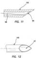
- the distal end 122 of the main body 112is illustrated in greater detail in Figs. 11 and 12 .
- the practitionerin directing the needle 54, aims for a target area 57, as shown in Fig. 12 .
- a pull wire 58having a snare loop 60 on its distal end, is extended distally through the primary lumen 114, until the snare loop 60 engages and captures the barb 56. Then, as illustrated in Fig. 10 , the pull wire 58 is retracted proximally, to firmly catch the piercing needle 54 with the barb 56, and to tighten the loop 62 formed by the piercing needle. Continuing to proximally withdraw the pull wire 58 will pull the wire loop 62 through the tissue forming the walls of both the first vessel 118 and the second vessel 120, as well as any intervening tissue 138, to form a desired elongated slit or aperture 142. If desired, the loop 62 may be energized to enhance the cutting action.
- the device 210comprises a vessel access sheath 264 ( Figs. 13 and 13A ) and a side access needle catheter 266 ( Figs. 14, 14A , 16A ).
- the side access needle catheter 266comprises a primary lumen 268 and a secondary lumen 270 ( Figs. 14 and 14A ).
- Fig. 15the side access needle catheter 266 has been inserted into the vessel access sheath 264, over a first guidewire 272.
- the first guidewire 272extends through the secondary lumen 270, as shown.
- Figs. 16 and 16Afurther illustrate the system 210, particularly a side access needle catheter assembly of the system.
- a side access needle 274has been inserted through a proximal end of the sheath 264 (the sheath is not shown in Fig. 16A , for clarity), extending distally through the primary lumen 268 and out of a side port 276 in the sheath 264.
- a second guidewire 278is inserted through a proximal end of the side access needle 274, and out of a distal end thereof, as shown.
- the side access needle catheter assemblycomprises each of the side access needle 274, side access catheter 266, and the second guidewire 278.
- a toggle delivery catheter 280constructed in accordance with the principles of the present invention is shown.
- the toggle delivery catheter 280has been inserted into the vessel access sheath 264 over the second guidewire 278.
- the toggle delivery catheterincludes a side port 282, which is substantially coincident with the side port 276 of the vessel access sheath when the vessel access sheath 264 and toggle delivery catheter 280 are assembled as shown.
- a toggle apparatus 284having a pivotable toggle member 285 attached to its distal end, has been inserted over the second guidewire 278 through the toggle delivery catheter 280, as shown.
- the practitionerselects an appropriate procedural site having each of a first vessel 287 and a second vessel 288 in close proximity to one another.
- the first vessel 287comprises a vein
- the second vessel288comprises an artery
- use of the device according to the inventionis not necessarily limited to this arrangement.
- one presently preferred locationis the hand 290 of a patient.
- the first vessel 287is punctured by a needle 292, which is inserted therein.
- the first guidewire 272is then inserted through the lumen of the hollow needle 292 into the vessel 287, and advanced in the direction of the arrow 293 ( Fig. 23 ). Following this, as shown in Fig. 24 , the needle 292 is removed, by withdrawing it in the direction of arrow 294.
- the next step in the methodis to install the vessel access sheath 264 over the first guidewire 272 and into the first vessel 287, advancing the sheath 264 in the direction of arrow 295.
- the sheath 264is fully inserted into the first vessel 287, so that the side port 276 is fully within the vessel, as shown in Fig. 26
- the side access needle catheter 266is installed into the sheath 264 in the direction of arrow 296 over the first guidewire 20, as illustrated in Fig. 27 (see also Fig. 15 ).
- the side access needle 274is advanced out of the side access needle catheter 266 and through side port 276, in the direction of arrow 297.
- the side access needle 274has a sharp distal tip 299, which punctures, respectively, the side walls of each of the first and second vessels 287, 288, as shown in Fig. 28 , so that the distal end of the side access needle 274 is disposed in the interior of the second vessel 288.
- the second guidewire 278is advanced through the lumen of the side access needle 274 and into the interior of the second vessel 288, in the direction of arrow 300.
- Fig. 30the first guidewire 272, side access needle 274, and side access needle catheter 266 have all been withdrawn from the procedural site, leaving the sheath 264 and second guidewire 278, which still extends from the first vessel287 into the second vessel 288, as shown.
- the toggle delivery catheter 280is inserted through the vessel access sheath 264 over the second guidewire 278.
- the toggle apparatus 284is advanced out of the side port 276 of the sheath, as shown in Fig. 31 , as well as in Figs. 19 and 20 .
- the toggle apparatus 284comprises the toggle member 285, which is pivotably disposed on a toggle shaft 302 by means of a pivot joint 304.
- the toggle apparatus 284has been advanced over the second guidewire 278 (not shown in this figure) into the interior of the second vessel (artery) 288.
- the toggle member 285is pivoted so that it is substantially parallel to the shaft 302, in a first, closed orientation, presenting essentially as the shaft 302 having a somewhat bulkier configuration at its distal end, and, optionally, a sharpened distal tip 305. Since the walls of both the first and second vessels have already been breached by the side access needle 274 earlier in the procedure, the toggle apparatus may be easily advanced into the second blood vessel 288, even without the assistance of the optional sharpened distal tip 305 or other cutting means.
- the toggle member 285is pivoted as illustrated in Fig. 32 , to a second, open orientation, so that its lengthwise orientation is generally parallel to the direction of blood flow through the vessel.
- the toggle apparatus 284is withdrawn proximally along the second guidewire 278, until the toggle member 285, in its open orientation, is pulled against the inner wall of the second vessel 288, at a location selected for the creation of an elongated aperture which will form the desired fistula.
- This actioninitially functions to pull the second vessel 288 into closer proximity to the first vessel 287.
- radio-frequency (RF) energyis applied to the length of the toggle member 285.
- the RF energyfunctions to burn and fuse or weld the vessels together, creating an elongate aperture 307 through the opposing walls of each of the first vessel 287 and second vessel288, as well as any intervening tissue.
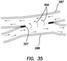
- This elongate aperture 307is shown in Figs. 34 and 35 .
- Alternative cutting approachessuch as resistive heat (hot wire), ultrasonic, or laser may be used instead of RF energy, if desired. Energy may also be applied to opposing surfaces of the toggle delivery catheter.
- the elongate aperture 307will typically resemble a slit, as shown in Fig. 34 .
- pressurized flow 309begins to occur through the slit or aperture 307 ( Fig. 35 ), which creates a communicating passage between the first vessel 287 and the second vessel288, the aperture widens responsive to the pressure, taking the shape of an ellipse as it opens to form the desired fistula.
- the edges of the apertureare cauterized and welded, following which the device 210 is removed from the procedural site, as shown in Fig. 35 . Tissue welding of the type intended to occur in the practice of these methods is discussed in U.S. Patent No. 6,908,463, to Treat et al. ,
- an important feature of the present inventionis the utilization of an energized apparatus, which may utilize RF energy, resistive heat, or other modalities as noted, to weld the tissue defining the aperture or communicating passage 307.
- This energymay be applied to the toggle, as noted above, or to a heater disposed in the catheter.
- Applicantshave advantageously designed the system to apply energy to both the catheter and the toggle member.
- a toggle heater 311may be disposed on the underside of the toggle member 285.
- a heater insert 313is disposed within the catheter, on a side thereof, as shown in Figs. 19 and 20 .
- the catheter systemhas the ability to apply heat or RF energy to both toggle heater 311 on the toggle member 285 and to the heater insert 313 on the side of the catheter.
- the heater insert 313is made of a resistive material that is connected to power wires, as will be described in more detail below.
- the surface of this heater insert 313is designed to mate with the toggle member 285, so that when the toggle is pulled proximally against the heater insert 313, as shown in Figs. 33-34 , the system can be removed from the apparatus through the sheath, as noted above.
- this mating arrangementalso allows pressure to be applied directly over the respective heating elements to induce cutting.
- the edges of the heater insert 313can be designed to disperse heat through material changes or shape to promote a lower temperature specific to protein denaturization, around 120-175 F.
- This space on the side access toggle delivery cathetercan also be filled with an ALNI (Aluminum Nitride Heater) or other high density heating elements, including versions of thick film and polyimide flex heaters.
- ALNIAluminum Nitride Heater
- the heater insert 313can also incorporate a collapsing motion or mechanism to facilitate removal, allowing the heater to move inwardly into the lumen space of the toggle delivery catheter. This motion of the heater insert 313 may also be employed to enhance cutting by allowing the toggle member 285 to move from the artery through the vein, and into the catheter.
- the direct mating and opposition of heater insert 313 to toggle surfaceis a primary mechanism, as described above, to apply direct pressure to the heating element.
- the toggle delivery catheter 280comprises a heat shield 315.
- the heater insert 313further comprises a weld cut zone 317 for mating with the toggle member 285, as discussed above.
- An end plug ramp insert 319is also illustrated.
- the catheter tube 280is machined to allow the heater insert 313 to sit down inside the shaft.
- Power wire inputs holes or lumens 321are formed in the heater insert 313 for receiving power connections for the heater.
- FIG. 38illustrates the catheter tube 280, in isolation, and particularly shows that the catheter tube is machined with multiple lumens 323, which function to convey the power wires to the power wire inputs holes 321, for supplying energy to the heater system.
- multiple lumens 323which function to convey the power wires to the power wire inputs holes 321, for supplying energy to the heater system.
- two such lumens 323are shown in Fig. 38 , for illustrative purposes, the scope of the present invention contemplates differing numbers, depending upon design considerations for a particular application. For example, in one such alternative embodiment, four lumens 323 would be used.
- Fig. 39illustrates one embodiment of the heater insert 313, apart from the system, as a whole, and thus more clearly showing its construction
- a modified embodiment of the heater insert 313ais shown.
- This embodimentparticularly comprises power connection slots 321a, rather than holes, as well as a guide wire slot 325.
- the open distal end of this particular designfunctions to make manipulation of the heater insert easier.
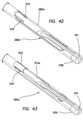
- Figs. 41-43illustrate a somewhat modified embodiment 210a of the catheter toggle delivery system in accordance with the present invention.
- like elementsare identified by like reference numerals, succeeded by the letter a, and only the differing features are discussed.
- this embodimentis designed to accommodate the modified heater insert 313a of Fig. 40 , and includes a guide wire slot 327 in its distal end.
- An end plug 329 on the distal end of the catheter tube 280ais shown in Figs. 42 and 43 , which also includes a guide wire slot 331.
- Power wires 333which run through the power wire lumens 323 and power wire inputs holes 321, for energizing the heater insert 313, 313a, are shown in Fig. 42 .
Landscapes
- Health & Medical Sciences (AREA)
- Life Sciences & Earth Sciences (AREA)
- Surgery (AREA)
- Engineering & Computer Science (AREA)
- Heart & Thoracic Surgery (AREA)
- Biomedical Technology (AREA)
- Animal Behavior & Ethology (AREA)
- General Health & Medical Sciences (AREA)
- Public Health (AREA)
- Veterinary Medicine (AREA)
- Nuclear Medicine, Radiotherapy & Molecular Imaging (AREA)
- Medical Informatics (AREA)
- Molecular Biology (AREA)
- Otolaryngology (AREA)
- Physics & Mathematics (AREA)
- Plasma & Fusion (AREA)
- Cardiology (AREA)
- Anesthesiology (AREA)
- Hematology (AREA)
- Vascular Medicine (AREA)
- Dentistry (AREA)
- Mechanical Engineering (AREA)
- Electromagnetism (AREA)
- Biophysics (AREA)
- Pulmonology (AREA)
- Pathology (AREA)
- Radiology & Medical Imaging (AREA)
- Surgical Instruments (AREA)
Description
- In the body, various fluids are transported through conduits throughout the organism to perform various essential functions. Blood vessels, arteries, veins, and capillaries carry blood throughout the body, carrying nutrients and waste products to different organs and tissues for processing. Bile ducts carry bile from the liver to the duodenum. Ureters carry urine from the kidneys to the bladder. The intestines carry nutrients and waste products from the mouth to the anus.
- In medical practice, there is often a need to connect conduits to one another or to a replacement conduit to treat disease or dysfunction of the existing conduits. The connection created between conduits is called an anastomosis.
- In blood vessels, anastomoses are made between veins and arteries, arteries and arteries, or veins and veins. The purpose of these connections is to create either a high flow connection, or fistula, between an artery and a vein, or to carry blood around an obstruction in a replacement conduit, or bypass. The conduit for a bypass is a vein, artery, or prosthetic graft.
- An anastomosis is created during surgery by bringing two vessels or a conduit into direct contact. The vessels are joined together with suture or clips. The anastomosis can be end-to-end, end-to-side, or side-to-side. In blood vessels, the anastomosis is elliptical in shape and is most commonly sewn by hand with a continuous suture. Other methods for anastomosis creation have been used including carbon dioxide laser, and a number of methods using various connecting prosthesis, clips, and stents.
- An arterio-venous fistula (AVF) is created by connecting an artery to a vein. This type of connection is used for hemodialysis, to increase exercise tolerance, to keep an artery or vein open, or to provide reliable access for chemotherapy.
- An alternative is to connect a prosthetic graft from an artery to a vein for the same purpose of creating a high flow connection between artery and vein. This is called an arterio-venous graft, and requires two anastomoses. One is between artery and graft, and the second is between graft and vein.
- A bypass is similar to an arteriovenous graft. To bypass an obstruction, two anastomoses and a conduit are required. A proximal anastomosis is created from a blood vessel to a conduit. The conduit extends around the obstruction, and a second distal anastomosis is created between the conduit and vessel beyond the obstruction.
- As noted above, in current medical practice, it is desirable to connect arteries to veins to create a fistula for the purpose of hemodialysis. The process of hemodialysis requires the removal of blood from the body at a rapid rate, passing the blood through a dialysis machine, and returning the blood to the body. The access to the blood circulation is achieved with catheters placed in large veins, prosthetic grafts attached to an artery and a vein, or a fistula where an artery is attached directly to the vein.
- Fistulas for hemodialysis are required by patients with kidney failure. The fistula provides a high flow of blood that can be withdrawn from the body into a dialysis machine to remove waste products and then returned to the body. The blood is withdrawn through a large access needle near the artery and returned to the fistula through a second large return needle. These fistulas are typically created in the forearm, upper arm, less frequently in the thigh, and in rare cases, elsewhere in the body. It is important that the fistula be able to achieve a flow rate of 500 ml per minute or greater. Dialysis fistulas have to be close to the skin (< 6 mm), and large enough (> 4 mm) to access with a large needle. The fistula needs to be long enough (> 6 em) to allow adequate separation of the access and return needle to prevent recirculation of dialysed and non-dialysed blood between the needles inserted in the fistula.
- Fistulas are created in anesthetized patients by carefully dissecting an artery and vein from their surrounding tissue, and sewing the vessels together with fine suture or clips. The connection thus created is an anastomosis. It is highly desirable to be able to make the anastomosis quickly, reliably, with less dissection, and with less pain. It is important that the anastomosis is the correct size, is smooth, and that the artery and vein are not twisted.
US 5 893 369 A discloses a device for creating an AV fistula comprising a main body with a sleeve and a punch having a hollow punch handle extending through the sleeve. A cutting edge is provided to cut through tissue.US2004/073238A discloses another apparatus for making incisions in body vessels.- The present invention comprises a device for creating an arteriovenous (AV) fistula, which comprises a first member comprising a main body having a primary lumen and a secondary lumen, and a second membercomprising a piercing member disposed in the secondary lumen, and configured to be moved distally out of the secondary lumen, and to cut through tissue while being distally moved. A third member extends from a distal end of the piercing member and is actuatable to move adjacent first and second blood vessels toward one another, and to create an elongated communicating aperture in opposing sides of each of the first vessel and the second vessel, wherein a source of energy is provided for application to the third member, for the purpose of energizing the third member for creating the elongated communicating aperture.
- The third member comprises a toggle member which is hinged to a distal end of the piercing member, and is pivotable between first and second orientations relative to the piercing member. The toggle member may have a sharp point on one end thereof.
- Further preferred and optional features are to be found amongst the sub-claims herewith.
- A source of RF (radio frequency) energy or resistive heat energy may be provided for application to the toggle member, for the said purpose of creating the elongated communicating aperture.
- The third member preferably comprises a pre-formed needle which is extendable from a distal end of the piercing member into a distal end of the primary lumen of the main body. A snare or other suitable apparatus may be disposed in the primary lumen for retracting in a proximal direction such a said needle.
- In use of the present device, a method (not claimed) of creating an AV fistula between adjacent first and second blood vessels may comprise a step of positioning a main body of such a device within the first vessel and extending a piercing member distally from the main body, through a wall of the first vessel, and through an adjacent wall of the second vessel, so that a distal end of the piercing member is disposed within the second vessel. A third member is actuated to move relative to a distal end of the piercing member for cutting an elongated communicating aperture on opposing walls of the first vessel and the second vessel. Preferably, the positioning step is performed percutaneously. The third member preferably comprises a pivotable toggle member, and the actuating step comprises pivoting the toggle member relative to the distal end of the piercing member. The actuating step further comprises applying a proximally directed tensile force on the toggle member so that the toggle member pulls the second vessel toward the first vessel.
- In one alternative, a method (not claimed) of using the present device further comprises a step of energizing the toggle member with RF energy, to cause a cutting action along the opposing walls of the first vessel and second vessel, in order to create the elongated communicating aperture. In another alternative such method, this further step is performed by energizing the toggle member with resistive heat energy, for the same purpose. In certain embodiments of the present device, the third member may comprise a pre-formed piercing needle and the actuating step comprises moving the pre-formed piercing needle so that an end thereof enters a distal end of the primary lumen. In these embodiments, the device further comprises a snare on a pull wire, disposed in the primary lumen, and
the actuating step further comprises using the snare to capture the pre-formed piercing needle. - A method (not claimed) of using the present device may further comprise a step of pulling the pull wire proximally, thereby moving the preformed piercing needle proximally to cause a cutting action along the opposing walls of the first vessel and second vessel, in order to create the elongated communicating aperture.
- In another example a system for creating an arteriovenous (AV) fistula, comprises a vessel access sheath having a hollow interior and an exit port, a side access needle catheter configured to fit within the hollow interior of the sheath, a needle configured to be inserted into a blood vessel through the side access needle catheter, a toggle delivery catheter configured to fit within the hollow interior of the sheath, and a toggle apparatus configured to be delivered into a vessel through the toggle delivery catheter. The toggle apparatus comprises a shaft and a toggle member pivotably attached to a distal end of the
shaft. - A source of RF energy or resistive heat energy may be provided for application to the toggle member, for purposes that may include creating an elongated communicating aperture between two adjacent blood vessels, such as an artery and a vein, or applying energy to the vessel surface that opposes the toggle member.
- The side access needle catheter preferably comprises a primary lumen and a secondary lumen. The toggle member may be actuated between an extended distal position and a retracted proximal position using the shaft.
- A heater may be provided in the toggle delivery catheter for the purpose of creating an elongated communicating aperture between two adjacent vessels. In such a case, the heater may comprise a heater insert which is structurally separate from, or, alternatively, integral with the toggle delivery catheter. In the structurally separate embodiments, the heater insert may be removed from the toggle delivery catheter. Preferably, the heater insert comprises a surface which is adapted to mate with the toggle member when the toggle member is retracted to a proximal position, and comprises a resistive material. The heater insert may also comprise a weld cut zone and a guide wire slot, as well as apertures for conveying power wires to the heater insert.
- In a presently preferred embodiment, the aforementioned source of RF or resistive heat energy is applied both to the toggle member and to the heater insert, for the purpose of creating an elongated communicating aperture between two adjacent vessels.
- A not claimed method of creating an AV fistula between adjacent first and second vessels, comprises steps of inserting a first guidewire into the first vessel, positioning a hollow vessel access sheath within the first vessel over the first guidewire, inserting a needle into the sheath, and using the needle to pierce a side wall of the first vessel and a side wall of the adjacent second vessel. Additional method steps include advancing the needle
so that a distal end thereof enters the second vessel, inserting a second guidewire through the needle from the first vessel into the second vessel, withdrawing the first guidewire and the needle from the procedural site, and inserting a toggle delivery catheter into the sheath over the second guidewire. At this juncture, a toggle apparatus comprising a shaft and a pivotable toggle member attached to a distal end of the shaft is advanced over the second guidewire so that the toggle member is disposed within the second vessel. The toggle member is moved proximally to contact the wall of the second vessel, and an aperture is created through the wall of one of the two vessels. Alternative approaches may include removing tissue roughly the size and shape of the toggle member via burning or vaporization. The toggle member moving step includes pivoting the toggle member so that the length of the toggle member is in contact with the wall of the second vessel. - In one approach , the aperture creating step comprises a step of creating the aperture through the walls of both vessels, wherein the apertures in the walls of each of the first and second vessels together create a communicating aperture between said vessels to create said AV fistula. Advantageously, as the energized member (or members) cuts or ablates the tissue to create the communicating aperture, the tissue edges defining the aperture are welded and sealed to create a finished edge and thus prevent further tissue damage after the AV fistula is completed, and to hermetically seal the tissue to prevent blood loss.
- The above noted energized member may comprise the toggle member, or a heater disposed in the toggle delivery catheter, or, preferably, both, so that the aperture creating step comprises energizing the toggle member and the heater, and applying the energized toggle member and the energized heater to opposing sides of the tissue through which the aperture is to be formed. The heater preferably comprises a heater insert which is removable from the toggle delivery catheter.
- The invention, together with additional features and advantages thereof, may best be understood by reference to the following description taken in conjunction with the accompanying illustrative drawings.
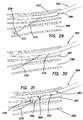
Fig. 1 is a view of one embodiment of the device of the present invention, wherein the device has been percutaneously or surgically positioned at a desired procedural location in a blood vessel;Fig. 2 is a view illustrating a shaft and toggle member of the present invention in isolation;Fig. 3 is a view similar toFig. 1 , wherein the toggle member illustrated inFig. 2 has been extended out of the first blood vessel and into an adjacent second blood vessel;Fig. 4 is a view similar toFig. 3 , wherein tension has been applied to the toggle member to actuate it and to cause the second blood vessel to be pulled into a position closely adjacent to the first vessel;Fig. 5 illustrates the fistula created by the device after the inventive device ofFigs. 1-4 has been withdrawn from the procedural site;Fig. 6 illustrates a communicating lumen created between the first and second vessels;Fig. 7 is a view similar toFig. 1 illustrating a second modified embodiment of the device of the present invention, wherein the device has been percutaneously or surgically positioned at a desired procedural location in a first blood vessel;Fig. 8 is a view similar toFig. 7 , wherein the secondary piercing element of the device has been extended out of the first vessel and into an adjacent second vessel;Fig. 9 is a view similar toFigs. 7 and 8 , wherein a preformed piercing needle has been extended from the secondary piercing element and into a distal end of the main body of the device;Fig. 10 is a view similar toFig. 9 , wherein a snare has been extended through the main body of the device to catch and secure, then proximally pull the piercing needle therethrough;Fig. 11 is a side view of the distal tip of the main body in isolation;Fig. 12 is a top view of the distal tip shown inFig. 11 ;Fig. 13 is a plan view of a vessel access sheath for use in yet another method;Fig. 13A is an isometric view of the sheath ofFig. 13 ;Fig. 14 is a cross-sectional view of the side access portion of a needle catheter for use with the sheath ofFig. 13 ;Fig. 14A is a cross-sectional view taken along thelines 14A-14A ofFig. 14 ;Fig. 15 is a cross-sectional view of the catheter inserted into the vessel access sheath ofFig. 13 , over a guidewire;Fig. 16 is a cross-sectional view similar toFig. 15 of the side access needle and guidewire inserted into the catheter;Fig. 16A is an isometric view of the side access needle catheter shown inFigs. 14-16 ;Fig. 17 is a cross-sectional view of the toggle delivery catheter of the embodiment ofFigs. 13-16 ;Fig. 18 is a cross-sectional view similar toFig. 17 , wherein the toggle delivery catheter has been inserted into the sheath;Fig. 19 is a cross-sectional view similar toFigs 17 and 18 wherein the toggle member has been inserted over the side access guidewire;Fig. 20 is an isometric view of the device as shown inFig. 19 ;Fig. 21 is an isometric view showing the first step of a method for creating an AV fistula using the toggle delivery catheter embodiment illustrated inFigs. 13-20 ;Fig. 22 is a view similar toFig. 21 , wherein a needle has been inserted into a vessel in the hand of a patient;Fig. 23 is a view illustrating the insertion of a guidewire through the needle into the vessel;Fig. 24 is a view similar toFig. 23 wherein the needle has been withdrawn and removed;Fig. 25 is a view similar toFigs. 23 and 24 , wherein a sheath has been inserted over the guidewire;Fig. 26 is a view similar toFigs. 23-25 , wherein the sheath has been advanced farther into the vessel;Fig. 27 is a view similar toFig. 26 , wherein the side access needle catheter has been inserted through the sheath;Fig. 28 is a view similar toFig. 27 , wherein the side access needle has been advanced into a second adjacent vessel;Fig. 29 is a view similar toFig. 28 , wherein a second guidewire has been advanced through the side access needle;Fig. 30 is a view similar toFig. 29 , wherein the first guidewire, side access needle, and side access needle catheter have all been removed, and the second guidewire remains in position;Fig. 31 is a view similar toFig. 30 , wherein the toggle delivery catheter with toggle member has been inserted, and the toggle member is being advanced over the second guidewire;Fig. 32 is a view similar toFig. 31 , wherein the toggle member has been advanced into the second vessel;Fig. 33 is a view similar toFig 32 wherein the toggle member has rotated and adjusted its length to align with the plane of the vessel into which it was inserted, after which it has been withdrawn proximally to cinch the two vessels together;Fig. 34 is a view similar toFig. 33 wherein the toggle has been pulled through the walls of the two vessels;Fig. 35 illustrates a completed AV fistula after the toggle and access sheath have been removed;Fig. 36 is an isometric view of the toggledelivery catheter embodiment 210 ofFigs. 13-20 , illustrating structural details of the toggle heater insert;Fig. 37 is an isometric view similar toFig. 36 , wherein the heat shield has been removed for illustrative clarity;Fig. 38 is an isometric view of the toggle insertion sheath of the toggle delivery catheter embodiment, illustrating multiple lumens for carrying power wires to the toggle heater insert;Fig. 39 is an isometric view of one embodiment of a toggle heater insert;Fig. 40 is an isometric view of another embodiment of a toggle heater insert;Fig. 41 is an isometric view of an embodiment of the catheter toggle delivery system, with toggle heater insert;Fig. 42 is an isometric view of a catheter tube for use with the catheter toggle delivery system, showing the end plug and power wires; andFig. 43 is an isometric view of the catheter tube ofFig. 42 , with the toggle heater insert in place.- Referring now more particularly to the drawings, there is shown in
Figs. 1-6 one embodiment of adevice 10 constructed in accordance with the principles of the present invention. As illustrated inFig. 1 , thedevice 10 comprises amain body 12 having aprimary lumen 14 and asecondary lumen 16. To begin the method of creating an AV fistula, the practitioner selects an appropriate procedural site having each of afirst blood vessel 18 and a second blood vessel20 in close proximity to one another. In currently preferred approaches, thefirst blood vessel 18 comprises a vein, and thesecond blood vessel 20 comprises an artery, but the method is not necessarily limited to this arrangement. Themain body 12 is inserted into thefirst vessel 18, as illustrated, so that adistal end 22 thereof lies within the blood flow passage of the first vessel. Preferably, this insertion step is performed using a percutaneous technique, but surgery may also be employed, if desired. - With reference now particularly to
Fig. 2 , a piercingtoggle member 24, which comprises a part of thedevice 10, is shown. The piercingtoggle member 24 comprises ashaft 26 and atoggle bar 28. Thetoggle bar 28 is preferably constructed to have asharp point 30 on one end thereof. It is pivotally attached, by means of ahinge point 32, to a distal end of theshaft 26. - As illustrated in
Fig. 2 , thetoggle bar 28 is pivotable between two primary orientations. A first, or closed,orientation 34 is shown in solid outline, while a second, or open,orientation 36 is shown in dotted outline. As will be described more fully below, theclosed orientation 34 is utilized during the initial device insertion steps, as well as the device withdrawal steps, while theopen orientation 36 is the operative orientation for creating the fistula. Thetoggle bar 28 is biased, by suitable means, to theclosed orientation 34. - Referring once again to
Fig. 1 , it can be seen that the piercingtoggle member 24 is inserted into thesecondary lumen 16 of themain body 12, with thetoggle bar 28 disposed, in itsclosed orientation 34, at a distal end of the secondary lumen. - Now, with reference to
Fig. 3 , it can be seen that the piercingtoggle member 24 has been advanced distally so that it has exited a distal end of thesecondary lumen 16 and through an aperture (not shown) provided in the wall of the main body. Additionally, using thesharp point 30 of thetoggle bar 28, in itsclosed orientation 34, thetoggle bar 28 andshaft 26 has been advanced through thefirst vessel 18, piercing the wall of the first vessel,tissue 38 between the first vessel and thesecond vessel 20, and the wall of thesecond vessel 20, so that thetoggle bar 28 and distal end of theshaft 26 is now disposed within thesecond vessel 20. - Once the distal end of the piercing
toggle member 24, and thetoggle bar 28, is positioned within thesecond vessel 20, thetoggle bar 28 may be pivoted or deployed to itsopen orientation 36, as shown inFig. 4 . Tensile force is then applied proximally on theshaft 26 of the piercingtoggle member 24, alongarrow 40, to move thetoggle bar 28 into contact with the second vessel wall, at the selected location for the creation of an elongated aperture which will form the desired fistula. This action initially functions to pull thesecond vessel 20 into closer proximity to thefirst vessel 18. Then, in one embodiment, radio-frequency (RF) energy is applied to thetoggle bar 28. The RF energy functions to burn anelongate aperture 42 through the opposing walls of each of thefirst vessel 18 andsecond vessel 20, as well as any interveningtissue 38. Thiselongate aperture 42 is shown inFigs. 5 and 6 . Alternative cutting approaches, such as resistive heat (hot wire), ultrasonic, laser, or mechanical approaches, may be used instead of RF energy, if desired. - As formed, the
elongate aperture 42 will typically resemble a slit. However, aspressurized blood flow 44 begins to occur through theslit 42, which creates a communicating passage between thefirst vessel 18 and the second vessel20, the slit widens responsive to the pressure to form the desired fistula. Theedges 46 of the aperture are cauterized, following which thedevice 10 is removed from the procedural site. - Now, referring particularly to
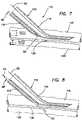
Figs. 7-12 , an alternative embodiment of adevice 110 and not claimed methods of using it are described, wherein like reference numerals identify like elements, preceded by the numeral 1. This embodiment functions similarly to the embodiment ofFigs. 1-6 in many ways, but is significantly different as well. These differences will be emphasized in the following description. - As in the previous embodiment, the
device 110 comprises amain body 112 having aprimary lumen 114 and asecondary lumen 116. As shown inFig. 7 , thedevice 110 is inserted, preferably percutaneously, into afirst blood vessel 118 at a desired procedural site. A secondary piercingmember 48 is inserted into thesecondary lumen 116. This secondary piercingmember 48 has a sharpdistal end 50. - In
Fig. 8 , the secondary piercing member has been advanced distally, along the direction ofarrow 52, so that the sharpdistal end 50 exits the distal end of thesecondary lumen 116 and an aperture (not shown) in the wall of themain body 112, extends through thefirst vessel 118 and its wall,tissue 138, and the wall of a second blood vessel120. Thus, when fully extended, after piercing through the noted tissue, the sharpdistal end 50 of the secondary piercingmember 48 is disposed within thesecond vessel 120, as shown. - As shown now in
Fig. 9 , once the sharpdistal end 50 of the secondary piercingmember 48 is located within thesecond vessel 120, a preformed piercingneedle 54, having abarb 56 on its distal end, is actuated to extend distally from the sharpdistal end 50 of the secondary piercingmember 48, back through the second vessel wall and into thedistal end 122, and thus theprimary lumen 114, of themain body 112 of thedevice 110. Thedistal end 122 of themain body 112 is illustrated in greater detail inFigs. 11 and 12 . The practitioner, in directing theneedle 54, aims for atarget area 57, as shown inFig. 12 . Apull wire 58, having asnare loop 60 on its distal end, is extended distally through theprimary lumen 114, until thesnare loop 60 engages and captures thebarb 56. Then, as illustrated inFig. 10 , thepull wire 58 is retracted proximally, to firmly catch the piercingneedle 54 with thebarb 56, and to tighten theloop 62 formed by the piercing needle. Continuing to proximally withdraw thepull wire 58 will pull thewire loop 62 through the tissue forming the walls of both thefirst vessel 118 and thesecond vessel 120, as well as any interveningtissue 138, to form a desired elongated slit oraperture 142. If desired, theloop 62 may be energized to enhance the cutting action. - There is shown in
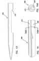
Figs. 13-20 yet another embodiment of an AV fistula device orsystem 210 constructed in accordance with the principles of the present invention. Thedevice 210 comprises a vessel access sheath 264 (Figs. 13 and13A ) and a side access needle catheter 266 (Figs. 14, 14A ,16A ). The sideaccess needle catheter 266 comprises aprimary lumen 268 and a secondary lumen 270 (Figs. 14 and 14A ). - In
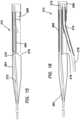
Fig. 15 , the sideaccess needle catheter 266 has been inserted into thevessel access sheath 264, over afirst guidewire 272. Thefirst guidewire 272 extends through thesecondary lumen 270, as shown. Figs. 16 and16A further illustrate thesystem 210, particularly a side access needle catheter assembly of the system. As shown, aside access needle 274 has been inserted through a proximal end of the sheath 264 (the sheath is not shown inFig. 16A , for clarity), extending distally through theprimary lumen 268 and out of aside port 276 in thesheath 264. Asecond guidewire 278 is inserted through a proximal end of theside access needle 274, and out of a distal end thereof, as shown. The side access needle catheter assembly comprises each of theside access needle 274,side access catheter 266, and thesecond guidewire 278.- Now referring to
Figs. 17 and 18 , atoggle delivery catheter 280 constructed in accordance with the principles of the present invention is shown. InFig. 18 , thetoggle delivery catheter 280 has been inserted into thevessel access sheath 264 over thesecond guidewire 278. The toggle delivery catheter includes aside port 282, which is substantially coincident with theside port 276 of the vessel access sheath when thevessel access sheath 264 and toggledelivery catheter 280 are assembled as shown. - In
Figs. 19 and 20 , atoggle apparatus 284, having apivotable toggle member 285 attached to its distal end, has been inserted over thesecond guidewire 278 through thetoggle delivery catheter 280, as shown. - The apparatus shown and described above in connection with
Figs. 13-20 will now be further described in conjunction with an explanation of a particular method (not claimed) by which thesystem 210 may be used to create an AV fistula. This method is illustrated more particularly inFigs. 21-35 . - To begin the method of creating an AV fistula, the practitioner selects an appropriate procedural site having each of a
first vessel 287 and asecond vessel 288 in close proximity to one another. In currently preferred approaches, thefirst vessel 287 comprises a vein, and the second vessel288 comprises an artery, but use of the device according to the invention is not necessarily limited to this arrangement. As illustrated inFig. 21 , one presently preferred location is thehand 290 of a patient. Then, generally employing principles of the Seldinger technique, as shown inFig. 22 , the first vessel
287 is punctured by aneedle 292, which is inserted therein. Thefirst guidewire 272 is then inserted through the lumen of thehollow needle 292 into thevessel 287, and advanced in the direction of the arrow 293 (Fig. 23 ). Following this, as shown inFig. 24 , theneedle 292 is removed, by withdrawing it in the direction ofarrow 294. - The next step in the method, as illustrated in
Fig. 25 , is to install thevessel access sheath 264 over thefirst guidewire 272 and into thefirst vessel 287, advancing thesheath 264 in the direction ofarrow 295. Once thesheath 264 is fully inserted into thefirst vessel 287, so that theside port 276 is fully within the vessel, as shown inFig. 26 , the sideaccess needle catheter 266 is installed into thesheath 264 in the direction ofarrow 296 over thefirst guidewire 20, as illustrated inFig. 27 (see alsoFig. 15 ). - Now, referring particularly to
Figs. 28 ,16 , and16A , theside access needle 274 is advanced out of the sideaccess needle catheter 266 and throughside port 276, in the direction ofarrow 297. Theside access needle 274 has a sharpdistal tip 299, which punctures, respectively, the side walls of each of the first andsecond vessels Fig. 28 , so that the distal end of theside access needle 274 is disposed in the interior of thesecond vessel 288. Then, as shown inFigs. 29 and16A , thesecond guidewire 278 is advanced through the lumen of theside access needle 274 and into the interior of thesecond vessel 288, in the direction ofarrow 300. - In
Fig. 30 , thefirst guidewire 272,side access needle 274, and sideaccess needle catheter 266 have all been withdrawn from the procedural site, leaving thesheath 264 andsecond guidewire 278, which still extends from the first vessel287 into thesecond vessel 288, as shown. - With reference now particularly to
Figs. 31 ,17, and 18 , thetoggle delivery catheter 280 is inserted through thevessel access sheath 264 over thesecond guidewire 278. Thetoggle apparatus 284 is advanced out of theside port 276 of the sheath, as shown inFig. 31 , as well as inFigs. 19 and 20 . Thetoggle apparatus 284 comprises thetoggle member 285, which is pivotably disposed on atoggle shaft 302 by means of apivot joint 304. - In
Fig. 32 , thetoggle apparatus 284 has been advanced over the second guidewire 278 (not shown in this figure) into the interior of the second vessel (artery) 288. To enter thevessel 288, thetoggle member 285 is pivoted so that it is substantially parallel to theshaft 302, in a first, closed orientation, presenting essentially as theshaft 302 having a somewhat bulkier configuration at its distal end, and, optionally, a sharpeneddistal tip 305. Since the walls of both the first and second vessels have already been breached by theside access needle 274 earlier in the procedure, the toggle apparatus may be easily advanced into thesecond blood vessel 288, even without the assistance of the optional sharpeneddistal tip 305 or other cutting means. Once entry of thetoggle member 285 into thesecond vessel 288 is achieved, thetoggle member 285 is pivoted as illustrated inFig. 32 , to a second, open orientation, so that its lengthwise orientation is generally parallel to the direction of blood flow through the vessel. - At this point, as illustrated in
Fig. 33 , thetoggle apparatus 284 is withdrawn proximally along thesecond guidewire 278, until thetoggle member 285, in its open orientation, is pulled against the inner wall of thesecond vessel 288, at a location selected for the creation of an elongated aperture which will form the desired fistula. This action initially functions to pull thesecond vessel 288 into closer proximity to thefirst vessel 287. Then, in one embodiment, radio-frequency (RF) energy is applied to the length of thetoggle member 285. The RF energy functions to burn and fuse or weld the vessels together, creating anelongate aperture 307 through the opposing walls of each of thefirst vessel 287 and second vessel288, as well as any intervening tissue. Thiselongate aperture 307 is shown inFigs. 34 and35 . Alternative cutting approaches, such as resistive heat (hot wire), ultrasonic, or laser may be used instead of RF energy, if desired. Energy may also be applied to opposing surfaces of the toggle delivery catheter. - As formed, the
elongate aperture 307 will typically resemble a slit, as shown inFig. 34 . However, aspressurized flow 309 begins to occur through the slit or aperture 307 (Fig. 35 ), which creates a communicating passage between thefirst vessel 287 and the second vessel288, the aperture widens responsive to the pressure, taking the shape of an ellipse as it opens to form the desired fistula. The edges of the aperture are cauterized and welded, following which thedevice 210 is removed from the procedural site, as shown inFig. 35 . Tissue welding of the type intended to occur in the practice of these methods is discussed inU.S. Patent No. 6,908,463, to Treat et al. , - As noted above, particularly in connection with the discussion of
Figs. 33-35 , an important feature of the present invention is the utilization of an energized apparatus, which may utilize RF energy, resistive heat, or other modalities as noted, to weld the tissue defining the aperture or communicatingpassage 307. This energy may be applied to the toggle, as noted above, or to a heater disposed in the catheter. In the present invention, however, Applicants have advantageously designed the system to apply energy to both the catheter and the toggle member. Thus, considering againFigs. 19 and 20 , atoggle heater 311 may be disposed on the underside of thetoggle member 285. Additionally, aheater insert 313 is disposed within the catheter, on a side thereof, as shown inFigs. 19 and 20 . A key feature of this arrangement is that the catheter system has the ability to apply heat or RF energy to bothtoggle heater 311 on thetoggle member 285 and to theheater insert 313 on the side of the catheter. In one resistive embodiment, theheater insert 313 is made of a resistive material that is connected to power wires, as will be described in more detail below. The surface of thisheater insert 313 is designed to mate with thetoggle member 285, so that when the toggle is pulled proximally against theheater insert 313, as shown inFigs. 33-34 , the system can be removed from the apparatus through the sheath, as noted above. However, this mating arrangement also allows pressure to be applied directly over the respective heating elements to induce cutting. The edges of theheater insert 313 can be designed to disperse heat through material changes or shape to promote a lower temperature specific to protein denaturization, around 120-175 F. This space on the side access toggle delivery catheter can also be filled with an ALNI (Aluminum Nitride Heater) or other high density heating elements, including versions of thick film and polyimide flex heaters. Theheater insert 313 can also incorporate a collapsing motion or mechanism to facilitate removal, allowing the heater to move inwardly into the lumen space of the toggle delivery catheter. This motion of theheater insert 313 may also be employed to enhance cutting by allowing thetoggle member 285 to move from the artery through the vein, and into the catheter. Finally, the direct mating and opposition ofheater insert 313 to toggle surface is a primary mechanism, as described above, to apply direct pressure to the heating element. - Referring now to
Figs. 36-38 , an embodiment of the cathetertoggle delivery system 210 is shown which illustrates a little more clearly the particular features of the heating system, and especially of theheater insert 313. Thetoggle delivery catheter 280 comprises aheat shield 315. Theheater insert 313 further comprises aweld cut zone 317 for mating with thetoggle member 285, as discussed above. An endplug ramp insert 319 is also illustrated. Thecatheter tube 280 is machined to allow theheater insert 313 to sit down inside the shaft. Power wire inputs holes or lumens 321 (Figs. 36 and 37 ) are formed in theheater insert 313 for receiving power connections for the heater.Fig. 38 illustrates thecatheter tube 280, in isolation, and particularly shows that the catheter tube is machined withmultiple lumens 323, which function to convey the power wires to the power wire inputs holes 321, for supplying energy to the heater system. It should be noted that, while twosuch lumens 323 are shown inFig. 38 , for illustrative purposes, the scope of the present invention contemplates differing numbers, depending upon design considerations for a particular application. For example, in one such alternative embodiment, fourlumens 323 would be used. Fig. 39 illustrates one embodiment of theheater insert 313, apart from the system, as a whole, and thus more clearly showing its construction- In
Fig. 40 , a modified embodiment of theheater insert 313a is shown. This embodiment particularly comprisespower connection slots 321a, rather than holes, as well as aguide wire slot 325. The open distal end of this particular design functions to make manipulation of the heater insert easier. Figs. 41-43 illustrate a somewhat modifiedembodiment 210a of the catheter toggle delivery system in accordance with the present invention. In this embodiment, like elements are identified by like reference numerals, succeeded by the letter a, and only the differing features are discussed. Specifically, this embodiment is designed to accommodate the modifiedheater insert 313a ofFig. 40 , and includes aguide wire slot 327 in its distal end. Anend plug 329 on the distal end of thecatheter tube 280a is shown inFigs. 42 and 43 , which also includes aguide wire slot 331.Power wires 333, which run through thepower wire lumens 323 and power wire inputs holes 321, for energizing theheater insert Fig. 42 .- Accordingly, although an exemplary embodiment according to the invention has been shown and described, it is to be understood that all the terms used herein are descriptive rather than limiting, and that many changes, modifications, and substitutions may be made by one having ordinary skill in the art without departing from the scope of the invention, which is to be limited only in accordance with the following claims.
Claims (7)
- A device for creating an arteriovenous (AV) fistula, comprising: a first member comprising a main body (12, 112) having a primary lumen (14, 114) and a secondary lumen (16, 116);a second member comprising a piercing member (24, 48) disposed in said secondary lumen, and configured to be capable of movement distally out of said secondary lumen, and capable of cutting through tissue while being distally moved,characterised in that there is further provided;a third member (28, 54) extending from a distal end of the piercing member and being actuatable to move adjacent first and second blood vessels toward one another and to create an elongated communicating aperture in opposing sides of each of the first vessel and the second vessel;wherein the third member comprises a toggle member (28) hinged to a distal end of the piercing member (24), and pivotable between first and second orientations relative to the piercing member; anda source of energy for application to the third member, capable of energising the third member to create said elongated communicating aperture.
- The device as recited in Claim 1, wherein said source of energy comprises a source of Radio-Frequency (RF) energy.
- The device as recited in Claim 1, wherein said source of energy comprises resistive heat energy.
- The device as recited in Claim 1, wherein the third member comprises a needle (54) which is extendable from a distal end of the piercing member (48) into a distal end of the primary lumen of the main body.
- The device as recited in Claim 4, and further comprising apparatus disposed in said primary lumen for retracting in a proximal direction said needle.
- The device as recited in claim 5, wherein said apparatus comprises a pull wire (58).
- The device as recited in claim 5, wherein said apparatus further comprises a snare loop (60).
Applications Claiming Priority (3)
| Application Number | Priority Date | Filing Date | Title |
|---|---|---|---|
| US35490310P | 2010-06-15 | 2010-06-15 | |
| US201161480486P | 2011-04-29 | 2011-04-29 | |
| PCT/US2011/040530WO2011159802A1 (en) | 2010-06-15 | 2011-06-15 | Systems and methods for creating arteriovenous (av) fistulas |
Publications (3)
| Publication Number | Publication Date |
|---|---|
| EP2582306A1 EP2582306A1 (en) | 2013-04-24 |
| EP2582306A4 EP2582306A4 (en) | 2017-04-26 |
| EP2582306B1true EP2582306B1 (en) | 2023-03-29 |
Family
ID=45096823
Family Applications (1)
| Application Number | Title | Priority Date | Filing Date |
|---|---|---|---|
| EP11796369.4AActiveEP2582306B1 (en) | 2010-06-15 | 2011-06-15 | Systems and methods for creating arteriovenous (av) fistulas |
Country Status (6)
| Country | Link |
|---|---|
| US (5) | US9445868B2 (en) |
| EP (1) | EP2582306B1 (en) |
| JP (2) | JP5864064B2 (en) |
| AU (1) | AU2011268411B2 (en) |
| CA (1) | CA2804524C (en) |
| WO (1) | WO2011159802A1 (en) |
Families Citing this family (32)
| Publication number | Priority date | Publication date | Assignee | Title |
|---|---|---|---|---|
| GB0419954D0 (en) | 2004-09-08 | 2004-10-13 | Advotek Medical Devices Ltd | System for directing therapy |
| US20130190676A1 (en) | 2006-04-20 | 2013-07-25 | Limflow Gmbh | Devices and methods for fluid flow through body passages |
| EP4032486A1 (en) | 2010-11-16 | 2022-07-27 | TVA Medical, Inc. | Devices for forming a fistula |
| JP6182545B2 (en)* | 2012-02-08 | 2017-08-16 | アベヌ メディカル インコーポレイテッドAvenu Medical,Inc. | Intravascular arteriovenous anastomosis and tissue junction catheter |
| US9486276B2 (en) | 2012-10-11 | 2016-11-08 | Tva Medical, Inc. | Devices and methods for fistula formation |
| CA2898879C (en) | 2013-03-08 | 2023-05-02 | Limflow Gmbh | Methods and systems for providing or maintaining fluid flow through body passages |
| CN105228683B (en) | 2013-03-14 | 2022-06-10 | Tva医疗公司 | Fistula-forming device and method for forming fistula |
| US10070866B1 (en)* | 2013-08-01 | 2018-09-11 | Avenu Medical, Inc. | Percutaneous arterial to venous anastomosis clip application catheter system and methods |
| US10292708B1 (en) | 2014-02-13 | 2019-05-21 | Avenu Medical, Inc. | Externally supported anastomosis |
| US10772672B2 (en) | 2014-03-06 | 2020-09-15 | Avenu Medical, Inc. | Systems and methods for percutaneous access and formation of arteriovenous fistulas |
| US10695534B2 (en) | 2014-03-14 | 2020-06-30 | Tva Medical, Inc. | Fistula formation devices and methods therefor |
| WO2016033374A1 (en) | 2014-08-27 | 2016-03-03 | Tva Medical, Inc. | Cryolipopysis devices and methods therefor |
| US10603040B1 (en) | 2015-02-09 | 2020-03-31 | Tva Medical, Inc. | Methods for treating hypertension and reducing blood pressure with formation of fistula |
| CN108366822B (en) | 2015-08-21 | 2021-02-19 | 艾凡诺医疗公司 | System and method for percutaneous arteriovenous fistula |
| JP7219090B2 (en)* | 2016-01-15 | 2023-02-07 | ティーブイエー メディカル, インコーポレイテッド | Systems and methods for gluing vessels |
| US10874422B2 (en) | 2016-01-15 | 2020-12-29 | Tva Medical, Inc. | Systems and methods for increasing blood flow |
| WO2017124062A1 (en) | 2016-01-15 | 2017-07-20 | Tva Medical, Inc. | Devices and methods for forming a fistula |
| CN114042224B (en) | 2016-01-15 | 2024-09-17 | Tva医疗公司 | Device and method for advancing a wire |
| CN109982652B (en) | 2016-09-25 | 2022-08-05 | Tva医疗公司 | Vascular stent device and method |
| US10764963B2 (en) | 2016-10-07 | 2020-09-01 | S. C. Johnson & Son, Inc. | Volatile material dispenser |
| EP3609415B1 (en) | 2017-04-10 | 2023-08-23 | LimFlow GmbH | Devices for treating lower extremity vasculature |
| WO2018213626A1 (en) | 2017-05-17 | 2018-11-22 | Avenu Medical, Inc. | Single catheter electrode tissue cutting system for creating anastomoses |
| US11937821B1 (en) | 2017-05-17 | 2024-03-26 | Avenu Medical, Inc. | Systems and methods for catheter feedback and control for AV fistula creation |
| WO2018236835A1 (en)* | 2017-06-19 | 2018-12-27 | The Regents Of The University Of California | DEVICE AND METHOD FOR ATRAUMATIC AND PERCUTANEOUS FORMATION OF AN ARTERIAL-VENOUS FISTULA |
| WO2020028848A1 (en) | 2018-08-03 | 2020-02-06 | Avenu Medical, Inc. | Fixation of vessels for percutaneous fistula creation |
| SG11202102500UA (en) | 2018-10-09 | 2021-04-29 | Limflow Gmbh | Devices and methods for catheter alignment |
| WO2020081597A1 (en)* | 2018-10-15 | 2020-04-23 | Aharon Alon S | Magnetic puncture access and delivery systems and methods |
| EP4051174A4 (en) | 2019-11-01 | 2023-11-22 | LimFlow GmbH | Devices and methods for increasing blood perfusion to a distal extremity |
| US20210213245A1 (en)* | 2020-01-09 | 2021-07-15 | Becton, Dickinson And Company | Multi-lumen extension system |
| CN112274240B (en)* | 2020-10-28 | 2021-08-27 | 青岛钰仁医疗科技有限公司 | Angle-variable plasma electrode cutter head |
| CA3204229A1 (en)* | 2021-01-13 | 2022-07-21 | Megan Scherich | Vascular access instrument advancement devices, systems, and methods |
| WO2025002537A1 (en)* | 2023-06-27 | 2025-01-02 | Clearstream Technologies Limited | Catheter for percutaneously creating an arteriovenous fistula and/or guidewire placement by itself in concomitant vessels |
Family Cites Families (75)
| Publication number | Priority date | Publication date | Assignee | Title |
|---|---|---|---|---|
| JPS5552748A (en) | 1978-10-12 | 1980-04-17 | Olympus Optical Co | Highhfrequency incising tool |
| US5409453A (en) | 1992-08-12 | 1995-04-25 | Vidamed, Inc. | Steerable medical probe with stylets |
| WO1992017121A1 (en) | 1991-04-05 | 1992-10-15 | Metcal, Inc. | Instrument for cutting, coagulating and ablating tissue |
| US5424731A (en) | 1991-06-24 | 1995-06-13 | The United States Of America As Represented By The United States Department Of Energy | Remote two-wire data entry method and device |
| US5290278A (en) | 1992-10-20 | 1994-03-01 | Proclosure Inc. | Method and apparatus for applying thermal energy to luminal tissue |
| US6056744A (en) | 1994-06-24 | 2000-05-02 | Conway Stuart Medical, Inc. | Sphincter treatment apparatus |
| US6068637A (en) | 1995-10-03 | 2000-05-30 | Cedar Sinai Medical Center | Method and devices for performing vascular anastomosis |
| US6302875B1 (en) | 1996-10-11 | 2001-10-16 | Transvascular, Inc. | Catheters and related devices for forming passageways between blood vessels or other anatomical structures |
| DE69633411T2 (en) | 1995-10-13 | 2005-10-20 | Transvascular, Inc., Menlo Park | METHOD AND DEVICE FOR PREVENTING ARTERIAL ATTRACTIONS AND / OR FOR CARRYING OUT OTHER TRANSVASCULAR INTERVENTIONS |
| ATE440559T1 (en)* | 1995-10-13 | 2009-09-15 | Medtronic Vascular Inc | DEVICE FOR INTERSTITIAL TRANSVASCULAR PROCEDURES |
| US6726677B1 (en) | 1995-10-13 | 2004-04-27 | Transvascular, Inc. | Stabilized tissue penetrating catheters |
| US6283983B1 (en) | 1995-10-13 | 2001-09-04 | Transvascular, Inc. | Percutaneous in-situ coronary bypass method and apparatus |
| US6375615B1 (en) | 1995-10-13 | 2002-04-23 | Transvascular, Inc. | Tissue penetrating catheters having integral imaging transducers and their methods of use |
| US5769086A (en) | 1995-12-06 | 1998-06-23 | Biopsys Medical, Inc. | Control system and method for automated biopsy device |
| AU733341B2 (en) | 1996-02-02 | 2001-05-10 | Transvascular, Inc. | A device, system and method for interstitial transvascular intervention |
| US6709444B1 (en) | 1996-02-02 | 2004-03-23 | Transvascular, Inc. | Methods for bypassing total or near-total obstructions in arteries or other anatomical conduits |
| CA2244080A1 (en) | 1996-02-02 | 1997-08-07 | Transvascular, Inc. | Methods and apparatus for blocking flow through blood vessels |
| US5830224A (en) | 1996-03-15 | 1998-11-03 | Beth Israel Deaconess Medical Center | Catheter apparatus and methodology for generating a fistula on-demand between closely associated blood vessels at a pre-chosen anatomic site in-vivo |
| US6352535B1 (en) | 1997-09-25 | 2002-03-05 | Nanoptics, Inc. | Method and a device for electro microsurgery in a physiological liquid environment |
| US6379319B1 (en) | 1996-10-11 | 2002-04-30 | Transvascular, Inc. | Systems and methods for directing and snaring guidewires |
| US5893369A (en)* | 1997-02-24 | 1999-04-13 | Lemole; Gerald M. | Procedure for bypassing an occlusion in a blood vessel |
| US6626901B1 (en) | 1997-03-05 | 2003-09-30 | The Trustees Of Columbia University In The City Of New York | Electrothermal instrument for sealing and joining or cutting tissue |
| WO1998046115A2 (en) | 1997-04-11 | 1998-10-22 | Transvascular, Inc. | Methods and apparatus for transmyocardial direct coronary revascularization |
| US6071292A (en) | 1997-06-28 | 2000-06-06 | Transvascular, Inc. | Transluminal methods and devices for closing, forming attachments to, and/or forming anastomotic junctions in, luminal anatomical structures |
| US6083223A (en) | 1997-08-28 | 2000-07-04 | Baker; James A. | Methods and apparatus for welding blood vessels |
| DE19739699A1 (en) | 1997-09-04 | 1999-03-11 | Laser & Med Tech Gmbh | Electrode arrangement for the electro-thermal treatment of the human or animal body |
| US6330884B1 (en) | 1997-11-14 | 2001-12-18 | Transvascular, Inc. | Deformable scaffolding multicellular stent |
| US6077260A (en) | 1998-02-19 | 2000-06-20 | Target Therapeutics, Inc. | Assembly containing an electrolytically severable joint for endovascular embolic devices |
| AU762604B2 (en)* | 1998-03-31 | 2003-06-26 | Transvascular, Inc. | Catheters, systems and methods for percutaneous in situ arterio-venous bypass |
| US6561998B1 (en) | 1998-04-07 | 2003-05-13 | Transvascular, Inc. | Transluminal devices, systems and methods for enlarging interstitial penetration tracts |
| US6248983B1 (en) | 1998-10-22 | 2001-06-19 | Japan Servo Co., Ltd. | Heater control apparatus with variable input voltage rectification |
| US6235027B1 (en) | 1999-01-21 | 2001-05-22 | Garrett D. Herzon | Thermal cautery surgical forceps |
| US6626921B2 (en)* | 1999-04-16 | 2003-09-30 | Integrated Vascular Interventional Technologies, L.C. | Externally positioned anvil apparatus for cutting anastomosis |
| US6248117B1 (en)* | 1999-04-16 | 2001-06-19 | Vital Access Corp | Anastomosis apparatus for use in intraluminally directed vascular anastomosis |
| US6391038B2 (en) | 1999-07-28 | 2002-05-21 | Cardica, Inc. | Anastomosis system and method for controlling a tissue site |
| JP4166016B2 (en)* | 2000-01-04 | 2008-10-15 | メドトロニック ヴァスキュラー インコーポレイテッド | A device that forms a pathway between adjacent body lumens |
| US6558385B1 (en)* | 2000-09-22 | 2003-05-06 | Tissuelink Medical, Inc. | Fluid-assisted medical device |
| US6464665B1 (en) | 2000-07-05 | 2002-10-15 | Richard R. Heuser | Catheter apparatus and method for arterializing a vein |
| US6699245B2 (en) | 2001-02-05 | 2004-03-02 | A-Med Systems, Inc. | Anastomosis system and related methods |
| US7083618B2 (en) | 2001-04-06 | 2006-08-01 | Sherwood Services Ag | Vessel sealer and divider |
| US7029482B1 (en) | 2002-01-22 | 2006-04-18 | Cardica, Inc. | Integrated anastomosis system |
| US7223274B2 (en) | 2002-01-23 | 2007-05-29 | Cardica, Inc. | Method of performing anastomosis |
| US7074220B2 (en) | 2002-04-03 | 2006-07-11 | Thomas J. Fogarty | Methods and systems for vein harvesting and fistula creation |
| US7191015B2 (en) | 2002-04-11 | 2007-03-13 | Medtronic Vascular, Inc. | Devices and methods for transluminal or transthoracic interstitial electrode placement |
| US7351247B2 (en) | 2002-09-04 | 2008-04-01 | Bioconnect Systems, Inc. | Devices and methods for interconnecting body conduits |
| US6960209B2 (en)* | 2002-10-23 | 2005-11-01 | Medtronic, Inc. | Electrosurgical methods and apparatus for making precise incisions in body vessels |
| JP4109092B2 (en) | 2002-11-21 | 2008-06-25 | オリンパス株式会社 | High frequency knife |
| US8021359B2 (en)* | 2003-02-13 | 2011-09-20 | Coaptus Medical Corporation | Transseptal closure of a patent foramen ovale and other cardiac defects |
| JP4068989B2 (en) | 2003-02-20 | 2008-03-26 | オリンパス株式会社 | High frequency treatment tool |
| US8021362B2 (en) | 2003-03-27 | 2011-09-20 | Terumo Kabushiki Kaisha | Methods and apparatus for closing a layered tissue defect |
| US7293562B2 (en)* | 2003-03-27 | 2007-11-13 | Cierra, Inc. | Energy based devices and methods for treatment of anatomic tissue defects |
| US7632266B2 (en)* | 2004-02-17 | 2009-12-15 | Boston Scientific Scimed, Inc. | Endoscopic devices and related methods of use |
| US7255675B2 (en)* | 2004-03-23 | 2007-08-14 | Michael Gertner | Devices and methods to treat a patient |
| EP1750607A2 (en) | 2004-06-02 | 2007-02-14 | Medtronic, Inc. | Loop ablation apparatus and method |
| US20100145331A1 (en) | 2004-06-02 | 2010-06-10 | Chrisitian Steven C | Loop Ablation Apparatus and Method |
| US7824408B2 (en) | 2004-08-05 | 2010-11-02 | Tyco Healthcare Group, Lp | Methods and apparatus for coagulating and/or constricting hollow anatomical structures |
| US20060111704A1 (en) | 2004-11-22 | 2006-05-25 | Rox Medical, Inc. | Devices, systems, and methods for energy assisted arterio-venous fistula creation |
| US8328797B2 (en) | 2004-12-23 | 2012-12-11 | C. R. Bard, Inc. | Blood vessel transecting and anastomosis |
| US7625372B2 (en) | 2005-02-23 | 2009-12-01 | Vnus Medical Technologies, Inc. | Methods and apparatus for coagulating and/or constricting hollow anatomical structures |
| US8197472B2 (en) | 2005-03-25 | 2012-06-12 | Maquet Cardiovascular, Llc | Tissue welding and cutting apparatus and method |
| US7918848B2 (en) | 2005-03-25 | 2011-04-05 | Maquet Cardiovascular, Llc | Tissue welding and cutting apparatus and method |
| JP4345703B2 (en)* | 2005-03-31 | 2009-10-14 | 日本ゼオン株式会社 | Electric treatment instrument |
| JP4643361B2 (en)* | 2005-05-30 | 2011-03-02 | オリンパス株式会社 | Endoscope treatment tool and endoscope treatment tool system |
| US7615050B2 (en) | 2005-06-27 | 2009-11-10 | Boston Scientific Scimed, Inc. | Systems and methods for creating a lesion using transjugular approach |
| US8402974B2 (en)* | 2006-05-30 | 2013-03-26 | Coherex Medical, Inc. | Methods, systems, and devices for sensing, measuring, and controlling closure of a patent foramen ovale |
| EP2035062A4 (en) | 2006-07-05 | 2013-01-16 | Jms North America Corp | Needle cover with site preparation tip |
| US20080051626A1 (en)* | 2006-08-28 | 2008-02-28 | Olympus Medical Systems Corp. | Fistulectomy method between first duct and second duct, ultrasonic endoscope, catheter with balloon, magnet retaining device, and magnet set |
| US8262626B2 (en) | 2007-10-23 | 2012-09-11 | Boston Scientific Scimed, Inc. | Apparatus and method for treating tissue |
| US8640940B2 (en) | 2008-04-30 | 2014-02-04 | Educational Foundation Jichi Medical University | Surgical system and surgical method for natural orifice transluminal endoscopic surgery (NOTES) |
| US9968396B2 (en) | 2008-05-27 | 2018-05-15 | Maquet Cardiovascular Llc | Surgical instrument and method |
| US9820746B2 (en) | 2008-07-28 | 2017-11-21 | Incube Laboratories LLC | System and method for scaffolding anastomoses |
| DE102009059196A1 (en)* | 2009-12-17 | 2011-06-22 | Aesculap AG, 78532 | Surgical system for connecting body tissue |
| US8623044B2 (en) | 2010-04-12 | 2014-01-07 | Ethicon Endo-Surgery, Inc. | Cable actuated end-effector for a surgical instrument |
| US8709035B2 (en) | 2010-04-12 | 2014-04-29 | Ethicon Endo-Surgery, Inc. | Electrosurgical cutting and sealing instruments with jaws having a parallel closure motion |
| EP4032486A1 (en) | 2010-11-16 | 2022-07-27 | TVA Medical, Inc. | Devices for forming a fistula |
- 2011
- 2011-06-15EPEP11796369.4Apatent/EP2582306B1/enactiveActive
- 2011-06-15CACA2804524Apatent/CA2804524C/enactiveActive
- 2011-06-15WOPCT/US2011/040530patent/WO2011159802A1/enactiveApplication Filing
- 2011-06-15AUAU2011268411Apatent/AU2011268411B2/enactiveActive
- 2011-06-15JPJP2013515482Apatent/JP5864064B2/enactiveActive
- 2011-06-15USUS13/161,182patent/US9445868B2/enactiveActive
- 2013
- 2013-12-04USUS14/096,973patent/US9439728B2/enactiveActive
- 2015
- 2015-12-22JPJP2015250535Apatent/JP6174672B2/enactiveActive
- 2016
- 2016-09-01USUS15/254,646patent/US10751461B2/enactiveActive
- 2020
- 2020-07-24USUS16/938,841patent/US11690944B2/enactiveActive
- 2023
- 2023-05-19USUS18/320,817patent/US20230302214A1/enactivePending
Also Published As
| Publication number | Publication date |
|---|---|
| CA2804524C (en) | 2018-04-10 |
| JP5864064B2 (en) | 2016-02-17 |
| US9439728B2 (en) | 2016-09-13 |
| EP2582306A4 (en) | 2017-04-26 |
| US10751461B2 (en) | 2020-08-25 |
| US20230302214A1 (en) | 2023-09-28 |
| WO2011159802A1 (en) | 2011-12-22 |
| JP6174672B2 (en) | 2017-08-02 |
| US20170087294A1 (en) | 2017-03-30 |
| JP2013528472A (en) | 2013-07-11 |
| JP2016093528A (en) | 2016-05-26 |
| US9445868B2 (en) | 2016-09-20 |
| US11690944B2 (en) | 2023-07-04 |
| AU2011268411A1 (en) | 2013-01-24 |
| AU2011268411B2 (en) | 2014-11-27 |
| US20110306993A1 (en) | 2011-12-15 |
| US20140094791A1 (en) | 2014-04-03 |
| CA2804524A1 (en) | 2011-12-22 |
| US20200353153A1 (en) | 2020-11-12 |
| EP2582306A1 (en) | 2013-04-24 |
Similar Documents
| Publication | Publication Date | Title |
|---|---|---|
| US11690944B2 (en) | Systems and methods for creating arteriovenous (AV) fistulas | |
| US11950828B2 (en) | Intravascular arterial to venous anastomosis and tissue welding catheter | |
| US9931164B2 (en) | Intravascular arterial to venous anastomosis and tissue welding catheter | |
| US11786299B2 (en) | Single catheter electrode tissue cutting system for creating anastomoses | |
| AU2015200498B2 (en) | Systems and methods for creating arteriovenous (AV) fistulas |
Legal Events
| Date | Code | Title | Description |
|---|---|---|---|
| PUAI | Public reference made under article 153(3) epc to a published international application that has entered the european phase | Free format text:ORIGINAL CODE: 0009012 | |
| 17P | Request for examination filed | Effective date:20130110 | |
| AK | Designated contracting states | Kind code of ref document:A1 Designated state(s):AL AT BE BG CH CY CZ DE DK EE ES FI FR GB GR HR HU IE IS IT LI LT LU LV MC MK MT NL NO PL PT RO RS SE SI SK SM TR | |
| RIC1 | Information provided on ipc code assigned before grant | Ipc:A61B 18/14 20060101ALI20161125BHEP Ipc:A61B 17/11 20060101ALI20161125BHEP Ipc:A61B 18/00 20060101ALI20161125BHEP Ipc:A61B 17/08 20060101AFI20161125BHEP | |
| RA4 | Supplementary search report drawn up and despatched (corrected) | Effective date:20170323 | |
| RIC1 | Information provided on ipc code assigned before grant | Ipc:A61B 18/14 20060101ALI20170317BHEP Ipc:A61B 17/08 20060101AFI20170317BHEP Ipc:A61B 17/11 20060101ALI20170317BHEP Ipc:A61B 18/00 20060101ALI20170317BHEP | |
| RAP1 | Party data changed (applicant data changed or rights of an application transferred) | Owner name:AVENU MEDICAL, INC. Owner name:BAJA RESEARCH, LLC | |
| STAA | Information on the status of an ep patent application or granted ep patent | Free format text:STATUS: EXAMINATION IS IN PROGRESS | |
| 17Q | First examination report despatched | Effective date:20190816 | |
| GRAP | Despatch of communication of intention to grant a patent | Free format text:ORIGINAL CODE: EPIDOSNIGR1 | |
| STAA | Information on the status of an ep patent application or granted ep patent | Free format text:STATUS: GRANT OF PATENT IS INTENDED | |
| INTG | Intention to grant announced | Effective date:20221020 | |
| GRAS | Grant fee paid | Free format text:ORIGINAL CODE: EPIDOSNIGR3 | |
| GRAA | (expected) grant | Free format text:ORIGINAL CODE: 0009210 | |
| STAA | Information on the status of an ep patent application or granted ep patent | Free format text:STATUS: THE PATENT HAS BEEN GRANTED | |
| RAP1 | Party data changed (applicant data changed or rights of an application transferred) | Owner name:AVENU MEDICAL, INC. | |
| AK | Designated contracting states | Kind code of ref document:B1 Designated state(s):AL AT BE BG CH CY CZ DE DK EE ES FI FR GB GR HR HU IE IS IT LI LT LU LV MC MK MT NL NO PL PT RO RS SE SI SK SM TR | |
| REG | Reference to a national code | Ref country code:GB Ref legal event code:FG4D | |
| REG | Reference to a national code | Ref country code:CH Ref legal event code:EP | |
| REG | Reference to a national code | Ref country code:DE Ref legal event code:R096 Ref document number:602011073751 Country of ref document:DE | |
| REG | Reference to a national code | Ref country code:AT Ref legal event code:REF Ref document number:1556131 Country of ref document:AT Kind code of ref document:T Effective date:20230415 | |
| REG | Reference to a national code | Ref country code:IE Ref legal event code:FG4D | |
| REG | Reference to a national code | Ref country code:LT Ref legal event code:MG9D | |
| PG25 | Lapsed in a contracting state [announced via postgrant information from national office to epo] | Ref country code:RS Free format text:LAPSE BECAUSE OF FAILURE TO SUBMIT A TRANSLATION OF THE DESCRIPTION OR TO PAY THE FEE WITHIN THE PRESCRIBED TIME-LIMIT Effective date:20230329 Ref country code:NO Free format text:LAPSE BECAUSE OF FAILURE TO SUBMIT A TRANSLATION OF THE DESCRIPTION OR TO PAY THE FEE WITHIN THE PRESCRIBED TIME-LIMIT Effective date:20230629 Ref country code:LV Free format text:LAPSE BECAUSE OF FAILURE TO SUBMIT A TRANSLATION OF THE DESCRIPTION OR TO PAY THE FEE WITHIN THE PRESCRIBED TIME-LIMIT Effective date:20230329 Ref country code:LT Free format text:LAPSE BECAUSE OF FAILURE TO SUBMIT A TRANSLATION OF THE DESCRIPTION OR TO PAY THE FEE WITHIN THE PRESCRIBED TIME-LIMIT Effective date:20230329 Ref country code:HR Free format text:LAPSE BECAUSE OF FAILURE TO SUBMIT A TRANSLATION OF THE DESCRIPTION OR TO PAY THE FEE WITHIN THE PRESCRIBED TIME-LIMIT Effective date:20230329 | |
| REG | Reference to a national code | Ref country code:NL Ref legal event code:MP Effective date:20230329 | |
| REG | Reference to a national code | Ref country code:AT Ref legal event code:MK05 Ref document number:1556131 Country of ref document:AT Kind code of ref document:T Effective date:20230329 | |
| PG25 | Lapsed in a contracting state [announced via postgrant information from national office to epo] | Ref country code:SE Free format text:LAPSE BECAUSE OF FAILURE TO SUBMIT A TRANSLATION OF THE DESCRIPTION OR TO PAY THE FEE WITHIN THE PRESCRIBED TIME-LIMIT Effective date:20230329 Ref country code:NL Free format text:LAPSE BECAUSE OF FAILURE TO SUBMIT A TRANSLATION OF THE DESCRIPTION OR TO PAY THE FEE WITHIN THE PRESCRIBED TIME-LIMIT Effective date:20230329 Ref country code:GR Free format text:LAPSE BECAUSE OF FAILURE TO SUBMIT A TRANSLATION OF THE DESCRIPTION OR TO PAY THE FEE WITHIN THE PRESCRIBED TIME-LIMIT Effective date:20230630 Ref country code:FI Free format text:LAPSE BECAUSE OF FAILURE TO SUBMIT A TRANSLATION OF THE DESCRIPTION OR TO PAY THE FEE WITHIN THE PRESCRIBED TIME-LIMIT Effective date:20230329 | |
| PG25 | Lapsed in a contracting state [announced via postgrant information from national office to epo] | Ref country code:SM Free format text:LAPSE BECAUSE OF FAILURE TO SUBMIT A TRANSLATION OF THE DESCRIPTION OR TO PAY THE FEE WITHIN THE PRESCRIBED TIME-LIMIT Effective date:20230329 Ref country code:RO Free format text:LAPSE BECAUSE OF FAILURE TO SUBMIT A TRANSLATION OF THE DESCRIPTION OR TO PAY THE FEE WITHIN THE PRESCRIBED TIME-LIMIT Effective date:20230329 Ref country code:PT Free format text:LAPSE BECAUSE OF FAILURE TO SUBMIT A TRANSLATION OF THE DESCRIPTION OR TO PAY THE FEE WITHIN THE PRESCRIBED TIME-LIMIT Effective date:20230731 Ref country code:ES Free format text:LAPSE BECAUSE OF FAILURE TO SUBMIT A TRANSLATION OF THE DESCRIPTION OR TO PAY THE FEE WITHIN THE PRESCRIBED TIME-LIMIT Effective date:20230329 Ref country code:EE Free format text:LAPSE BECAUSE OF FAILURE TO SUBMIT A TRANSLATION OF THE DESCRIPTION OR TO PAY THE FEE WITHIN THE PRESCRIBED TIME-LIMIT Effective date:20230329 Ref country code:AT Free format text:LAPSE BECAUSE OF FAILURE TO SUBMIT A TRANSLATION OF THE DESCRIPTION OR TO PAY THE FEE WITHIN THE PRESCRIBED TIME-LIMIT Effective date:20230329 | |
| PG25 | Lapsed in a contracting state [announced via postgrant information from national office to epo] | Ref country code:SK Free format text:LAPSE BECAUSE OF FAILURE TO SUBMIT A TRANSLATION OF THE DESCRIPTION OR TO PAY THE FEE WITHIN THE PRESCRIBED TIME-LIMIT Effective date:20230329 Ref country code:PL Free format text:LAPSE BECAUSE OF FAILURE TO SUBMIT A TRANSLATION OF THE DESCRIPTION OR TO PAY THE FEE WITHIN THE PRESCRIBED TIME-LIMIT Effective date:20230329 Ref country code:IS Free format text:LAPSE BECAUSE OF FAILURE TO SUBMIT A TRANSLATION OF THE DESCRIPTION OR TO PAY THE FEE WITHIN THE PRESCRIBED TIME-LIMIT Effective date:20230729 | |
| REG | Reference to a national code | Ref country code:DE Ref legal event code:R097 Ref document number:602011073751 Country of ref document:DE | |
| PG25 | Lapsed in a contracting state [announced via postgrant information from national office to epo] | Ref country code:MC Free format text:LAPSE BECAUSE OF FAILURE TO SUBMIT A TRANSLATION OF THE DESCRIPTION OR TO PAY THE FEE WITHIN THE PRESCRIBED TIME-LIMIT Effective date:20230329 | |
| PG25 | Lapsed in a contracting state [announced via postgrant information from national office to epo] | Ref country code:MC Free format text:LAPSE BECAUSE OF FAILURE TO SUBMIT A TRANSLATION OF THE DESCRIPTION OR TO PAY THE FEE WITHIN THE PRESCRIBED TIME-LIMIT Effective date:20230329 Ref country code:DK Free format text:LAPSE BECAUSE OF FAILURE TO SUBMIT A TRANSLATION OF THE DESCRIPTION OR TO PAY THE FEE WITHIN THE PRESCRIBED TIME-LIMIT Effective date:20230329 Ref country code:CZ Free format text:LAPSE BECAUSE OF FAILURE TO SUBMIT A TRANSLATION OF THE DESCRIPTION OR TO PAY THE FEE WITHIN THE PRESCRIBED TIME-LIMIT Effective date:20230329 | |
| REG | Reference to a national code | Ref country code:CH Ref legal event code:PL | |
| PLBE | No opposition filed within time limit | Free format text:ORIGINAL CODE: 0009261 | |
| STAA | Information on the status of an ep patent application or granted ep patent | Free format text:STATUS: NO OPPOSITION FILED WITHIN TIME LIMIT | |
| REG | Reference to a national code | Ref country code:BE Ref legal event code:MM Effective date:20230630 | |
| GBPC | Gb: european patent ceased through non-payment of renewal fee | Effective date:20230629 | |
| PG25 | Lapsed in a contracting state [announced via postgrant information from national office to epo] | Ref country code:LU Free format text:LAPSE BECAUSE OF NON-PAYMENT OF DUE FEES Effective date:20230615 | |
| 26N | No opposition filed | Effective date:20240103 | |
| REG | Reference to a national code | Ref country code:IE Ref legal event code:MM4A | |
| PG25 | Lapsed in a contracting state [announced via postgrant information from national office to epo] | Ref country code:LU Free format text:LAPSE BECAUSE OF NON-PAYMENT OF DUE FEES Effective date:20230615 | |
| PG25 | Lapsed in a contracting state [announced via postgrant information from national office to epo] | Ref country code:IE Free format text:LAPSE BECAUSE OF NON-PAYMENT OF DUE FEES Effective date:20230615 | |
| PG25 | Lapsed in a contracting state [announced via postgrant information from national office to epo] | Ref country code:IE Free format text:LAPSE BECAUSE OF NON-PAYMENT OF DUE FEES Effective date:20230615 Ref country code:GB Free format text:LAPSE BECAUSE OF NON-PAYMENT OF DUE FEES Effective date:20230629 Ref country code:CH Free format text:LAPSE BECAUSE OF NON-PAYMENT OF DUE FEES Effective date:20230630 | |
| PG25 | Lapsed in a contracting state [announced via postgrant information from national office to epo] | Ref country code:SI Free format text:LAPSE BECAUSE OF FAILURE TO SUBMIT A TRANSLATION OF THE DESCRIPTION OR TO PAY THE FEE WITHIN THE PRESCRIBED TIME-LIMIT Effective date:20230329 | |
| PG25 | Lapsed in a contracting state [announced via postgrant information from national office to epo] | Ref country code:SI Free format text:LAPSE BECAUSE OF FAILURE TO SUBMIT A TRANSLATION OF THE DESCRIPTION OR TO PAY THE FEE WITHIN THE PRESCRIBED TIME-LIMIT Effective date:20230329 Ref country code:IT Free format text:LAPSE BECAUSE OF FAILURE TO SUBMIT A TRANSLATION OF THE DESCRIPTION OR TO PAY THE FEE WITHIN THE PRESCRIBED TIME-LIMIT Effective date:20230329 Ref country code:BE Free format text:LAPSE BECAUSE OF NON-PAYMENT OF DUE FEES Effective date:20230630 | |
| PG25 | Lapsed in a contracting state [announced via postgrant information from national office to epo] | Ref country code:BG Free format text:LAPSE BECAUSE OF FAILURE TO SUBMIT A TRANSLATION OF THE DESCRIPTION OR TO PAY THE FEE WITHIN THE PRESCRIBED TIME-LIMIT Effective date:20230329 | |
| PG25 | Lapsed in a contracting state [announced via postgrant information from national office to epo] | Ref country code:BG Free format text:LAPSE BECAUSE OF FAILURE TO SUBMIT A TRANSLATION OF THE DESCRIPTION OR TO PAY THE FEE WITHIN THE PRESCRIBED TIME-LIMIT Effective date:20230329 | |
| PGFP | Annual fee paid to national office [announced via postgrant information from national office to epo] | Ref country code:DE Payment date:20250520 Year of fee payment:15 | |
| PGFP | Annual fee paid to national office [announced via postgrant information from national office to epo] | Ref country code:FR Payment date:20250520 Year of fee payment:15 | |
| PG25 | Lapsed in a contracting state [announced via postgrant information from national office to epo] | Ref country code:CY Free format text:LAPSE BECAUSE OF FAILURE TO SUBMIT A TRANSLATION OF THE DESCRIPTION OR TO PAY THE FEE WITHIN THE PRESCRIBED TIME-LIMIT; INVALID AB INITIO Effective date:20110615 | |
| PG25 | Lapsed in a contracting state [announced via postgrant information from national office to epo] | Ref country code:HU Free format text:LAPSE BECAUSE OF FAILURE TO SUBMIT A TRANSLATION OF THE DESCRIPTION OR TO PAY THE FEE WITHIN THE PRESCRIBED TIME-LIMIT; INVALID AB INITIO Effective date:20110615 |