EP2581107A1 - Detection/stimulation microprobe implantable in venous, arterial or lymphatic networks - Google Patents
Detection/stimulation microprobe implantable in venous, arterial or lymphatic networksDownload PDFInfo
- Publication number
- EP2581107A1 EP2581107A1EP12187052.1AEP12187052AEP2581107A1EP 2581107 A1EP2581107 A1EP 2581107A1EP 12187052 AEP12187052 AEP 12187052AEP 2581107 A1EP2581107 A1EP 2581107A1
- Authority
- EP
- European Patent Office
- Prior art keywords
- microprobe
- strands
- core cable
- diameter
- microcable
- Prior art date
- Legal status (The legal status is an assumption and is not a legal conclusion. Google has not performed a legal analysis and makes no representation as to the accuracy of the status listed.)
- Ceased
Links
Images


Classifications
- A—HUMAN NECESSITIES
- A61—MEDICAL OR VETERINARY SCIENCE; HYGIENE
- A61B—DIAGNOSIS; SURGERY; IDENTIFICATION
- A61B5/00—Measuring for diagnostic purposes; Identification of persons
- A61B5/24—Detecting, measuring or recording bioelectric or biomagnetic signals of the body or parts thereof
- A—HUMAN NECESSITIES
- A61—MEDICAL OR VETERINARY SCIENCE; HYGIENE
- A61N—ELECTROTHERAPY; MAGNETOTHERAPY; RADIATION THERAPY; ULTRASOUND THERAPY
- A61N1/00—Electrotherapy; Circuits therefor
- A61N1/02—Details
- A61N1/04—Electrodes
- A61N1/05—Electrodes for implantation or insertion into the body, e.g. heart electrode
- A61N1/056—Transvascular endocardial electrode systems
- A—HUMAN NECESSITIES
- A61—MEDICAL OR VETERINARY SCIENCE; HYGIENE
- A61N—ELECTROTHERAPY; MAGNETOTHERAPY; RADIATION THERAPY; ULTRASOUND THERAPY
- A61N1/00—Electrotherapy; Circuits therefor
- A61N1/02—Details
- A61N1/04—Electrodes
- A61N1/05—Electrodes for implantation or insertion into the body, e.g. heart electrode
- A61N1/0526—Head electrodes
- A61N1/0529—Electrodes for brain stimulation
- A—HUMAN NECESSITIES
- A61—MEDICAL OR VETERINARY SCIENCE; HYGIENE
- A61N—ELECTROTHERAPY; MAGNETOTHERAPY; RADIATION THERAPY; ULTRASOUND THERAPY
- A61N1/00—Electrotherapy; Circuits therefor
- A61N1/02—Details
- A61N1/04—Electrodes
- A61N1/05—Electrodes for implantation or insertion into the body, e.g. heart electrode
- A61N1/0587—Epicardial electrode systems; Endocardial electrodes piercing the pericardium
- A—HUMAN NECESSITIES
- A61—MEDICAL OR VETERINARY SCIENCE; HYGIENE
- A61N—ELECTROTHERAPY; MAGNETOTHERAPY; RADIATION THERAPY; ULTRASOUND THERAPY
- A61N1/00—Electrotherapy; Circuits therefor
- A61N1/02—Details
- A61N1/04—Electrodes
- A61N1/05—Electrodes for implantation or insertion into the body, e.g. heart electrode
- A61N1/056—Transvascular endocardial electrode systems
- A61N2001/0585—Coronary sinus electrodes
- Y—GENERAL TAGGING OF NEW TECHNOLOGICAL DEVELOPMENTS; GENERAL TAGGING OF CROSS-SECTIONAL TECHNOLOGIES SPANNING OVER SEVERAL SECTIONS OF THE IPC; TECHNICAL SUBJECTS COVERED BY FORMER USPC CROSS-REFERENCE ART COLLECTIONS [XRACs] AND DIGESTS
- Y10—TECHNICAL SUBJECTS COVERED BY FORMER USPC
- Y10T—TECHNICAL SUBJECTS COVERED BY FORMER US CLASSIFICATION
- Y10T29/00—Metal working
- Y10T29/49—Method of mechanical manufacture
- Y10T29/49002—Electrical device making
- Y10T29/49117—Conductor or circuit manufacturing
- Y10T29/49194—Assembling elongated conductors, e.g., splicing, etc.
Definitions
- the inventionrelates generally to "active implantable medical devices" as defined by Council Directive 90/385 / EEC of 20 June 1990.
- This definitionincludes, in particular, cardiac implants responsible for monitoring cardiac activity and generating pacing, defibrillation and / or resynchronization pulses in the event of a rhythm disorder detected by the device. It also includes neurological devices, cochlear implants, diffusion pumps for medical substances, implanted biological sensors, etc.
- These devicescomprise a housing generally designated “generator”, electrically and mechanically connected to one or more intracorporeal “probes” provided with (s) electrodes intended to come into contact with the tissues on which it is desired to apply stimulation pulses and / or collect an electrical signal: myocardium, nerve, muscle, ...
- the present inventionmore specifically relates to a microprobe of detection / stimulation intended to be implanted in venous, arterial or lymphatic networks.
- the current architecture of the probes meeting these needscan be summarized as a generally hollow structure to allow the passage of a mandrel or a guide wire, and comprising insulated conductor cable components connected to mechanical electrodes for ensure electrical conductivity, radio-opacity ...
- the current size of the implantable probesis typically in the range of 4 to 6 French (1.33 to 2 mm) in their active part, ie the most distal part carrying the electrode or electrodes - even if the probe body, in the less distal part, uses smaller diameter conductors, as for example in the US 5,246,014A above, which, at the probe body, certainly includes a conductor whose diameter does not exceed 1 French (0.33 mm), but whose overall diameter of the distal active portion, at the location of the screw anchorage, is of several French.
- the object of the present inventionis to provide such a small "microprobe" which would be in accordance with the general properties of the implantable probes as enumerated above, while reducing its complexity and, therefore, done, the final cost.
- the size of this microprobeshould in particular make it possible to reach venules of very small dimensions, inaccessible today with devices of greater size.
- the microprobe of the inventionshould also facilitate substantially navigability in the venous, arterial or lymphatic networks because of its flexibility, amplified by its small size.
- this objectis achieved by means of a probe of a general type comprising, as disclosed by the US 5,246,014A mentioned above, a microcable having a diameter of not more than 2 French (0.66 mm), this microcable comprising: an electrically conductive core cable of diameter at most equal to 0.50 mm, formed by a strand of a plurality of strands of unit diameter at most equal to 40 microns, the core cable comprising a structuring material, in particular a stainless steel, cobalt alloy, precious metal, titanium or NiTi alloy, having a high resistance to fatigue; and a polymer insulation layer partially surrounding the core cable to a thickness of at most 30% of the core cable diameter.
- a structuring materialin particular a stainless steel, cobalt alloy, precious metal, titanium or NiTi alloy
- this probeis a microprobe consisting in its active portion, distal, by said microcable with a diameter of at most 2 French (0.66 mm).
- the core cable of the microcablehas a composite structure formed from, at least, said structuring material and a radiopaque material constituting at least about 0.008 mm 2 of the section of the core cable in a proportion to plus 50%.
- at least one stripped zoneis formed in the insulation layer so as to form at least one electrode on a cumulative total surface area at most equal to 20 mm 2 .
- stiffness degressivity meansare provided along the microprobe between its proximal portion and its distal portion.
- the microprobemay be rectilinear or, preferably, shaped at the level of the electrodes according to at least one electrical contact and mechanical stabilization preform
- the core cable constituting the microcable of the microprobe according to the inventionhas great flexibility, favorable to its handling by the doctor, especially during its implantation for example when it involves introducing it into networks of vessels with strong tortuosities and numerous branches and to avoid traumas that could lead to much more rigid probes, incompatible with the tissues.
- the choice of a stranded multifilament structure composed of very fine strands, with a unit diameter of at most 40 ⁇ m, preferably between 20 and 40 ⁇ m,makes it possible to increase the resistance to mechanical fatigue of the cable. of heart due to the movements of the patient and organs, knowing that the limit of bending rupture of a wire is substantially inversely proportional to its diameter.
- the strands themselvesto be made of a structuring material whose intrinsic fatigue resistance is high, such as for example the materials mentioned above. that is to say, stainless steels, cobalt alloys, titanium and NiTi alloy known in particular under the name of nitinol.
- the radiopaque materialmay be selected from tantalum (Ta), tungsten (W), iridium (Ir), platinum (Pt), gold (Au) and their alloys.
- the inventionprovides that the composite structure thus obtained of the core cable can be made by composite strands consisting, at least, of a structuring material and a radiopaque material, or by strands consisting of structuring material and strands made of radiopaque material.
- the plurality of strands of the strandadvantageously comprises between 15 and 300 strands.
- the inventionproposes a solution which consists in using the heart cable itself to form the electrodes of the microprobe by providing bare areas in an insulation layer surrounding the cable.
- the inventionrecommends that the insulation layer, preferably made of fluoropolymer, does not exceed in thickness 30% of the diameter of the core cable, this in order to avoid the effect of staircase at the edge of the electrodes which could impair electrical contact with tissue.
- the means of degressivity of rigiditythat is to say, which provide a decreasing stiffness from the proximal portion to the distal portion
- the means of decreasing stiffnesscan be achieved, in accordance with the invention, by a staged stack of tubes nested within each other, or by a succession of isodiameter tubes of increasing rigidity.
- microprobeonce in place, is stabilized in position by preforming, S or three-dimensional spiral, which also ensures permanent electrical contact of the electrodes with the tissues.
- microprobealso comprises local reinforcement means.
- the inventionrecommends that the strands comprise an outer layer of low magnetic susceptibility material, less than 2 .m 3 000.10 -12. mole -1 .
- the material with low magnetic susceptibilitycan be, alternatively, tantalum (Ta), titanium (Ti), rhodium (Rh), molybdenum (Mo), tungsten (W), palladium (Pd), gold (Au) and their alloys.
- the probes concerned by the inventionare microsondes of stimulation intended to be implanted in venous, arterial or lymphatic networks, and whose diameter does not exceed 2 French (0.66 mm). They are constituted in their active part, distal, by a microcable formed of a conductive core cable partially surrounded by an insulation layer defining at least one stimulation electrode.
- the service lifeis a fundamental parameter which must be absolutely taken into account when designing any medical device, in particular the microsondes of stimulation, objects of the invention. Indeed, the beating of the heart and the movement of the organs induce on this type of devices flexural deformations which must be perfectly controlled.
- This constraintfor example related to the heartbeat, may be experienced by the strand on 400.10 6 cycles over a period of 10 years, causing fatigue of the material may cause its rupture and limit its life.
- a microprobe of stimulation by the venous networkcan be the seat of deformations of curvature superior to a normal probe insofar as it must follow the deformations of the veins, which causes a greater stress and makes its resistance to fatigue more restrictive.
- the core cablea multiwire structure in the form of a strand of a plurality of conductive strands of small diameter d .
- the reduction in diameter of the unitary strandsmakes it possible reduce the stress applied to each of them and therefore increase the fatigue performance of the strand structure.
- a maximum deformation ⁇ Maxcorresponding to its fatigue strength limit for a number of deformation cycles equal, for example, to 100 ⁇ 10 6 .
- structural materiala material constituting the frame of the core cable, which will be called “structuring material”, must meet several criteria.
- the diameter of the unit strandmust be less than 35 ⁇ m. .
- a strand of 20 micronswill easily resist this stress, while a strand of 40 microns may cause a break before reaching the 100.10 6 cycles.
- the NiTi alloysexhibit maximum deformation ⁇ Max greater, from 5 to 9.10 -3 , offering even wider possibilities.
- a stainless steela cobalt alloy of the MP35N series, a precious metal, titanium or a NiTi alloy, of high fatigue resistance, to form a multi-filament structure whose strands have a diameter of not more than 40 ⁇ m, this dimension allowing on average to guarantee a maximum fatigue rupture strength under the extreme stress conditions to which such structures may be subjected.
- strands with a diameter of between 20 and 40 ⁇ mwill be considered, with smaller dimensions that may pose problems of technical feasibility and cost.
- the difficulty in this respectis to reconcile the fatigue resistance of the cable with the radiopacity as well as the resistance to corrosion.
- the most materials used for their X-ray visibilitynamely tantalum (Ta), tungsten (W), iridium (Ir), platinum (Pt), gold (Au) and their alloys, do not present not generally a great resistance to fatigue. This is why it is advantageous to adopt in this case a so-called composite cable structure in which a radiopaque material is added to the structuring material within the strand of single strands.
- the minimum presence of radiopaque material in the composite structureis estimated to be 0.008 mm 2 in the section of the core cable, but the proportion of radiopaque material opaque does not exceed 50%, in order not to degrade the mechanical properties of the strands ensured by the structuring material.
- the composite structure of the core cableis made by composite strands consisting, at least, of a structuring material 1 and a radiopaque material 2. More specifically, the Figure 1a represents a strand of which the structuring material 1 is outside the strand and the radiopaque material 2 inside. Conversely, in the strand of the Figure 1b , the structuring material 1 is inside and the radiopaque material 2 outside. The strand of the Figure 1c is made with an alloy 3 of structuring material and radiopaque material. Finally, the strand structure of the Figure 1d is more complex, with two outer and inner sections of radiopaque material 2 surrounding an intermediate section of structuring material 1.
- the strands 10 thus obtainedcan be stranded to form a core cable for the microprobe.
- the strand 12 of the Figure 2bis formed by the assembly of seven groups of seven strands 10.
- the Figure 2cshows a strand 13 of seven groups of 19 strands assembled according to the strand 11 of the Figure 2a .
- Even more complex structuresare illustrated on the Figures 2d to 2f .
- the core cable 14has a composite structure made not at the level of the strands but at the level of the cable itself.
- strands 10 1 made of structuring materialsurround strands 10 2 made of radiopaque material.
- the number of strands per strandit can be calculated that for a diameter of strands of 40 ⁇ m and a proportion of radio-opaque material of 50% occupying a section of 0.008 mm 2 , the total number of strands of all materials combined is of the order of fifteen strands. Conversely, for a strand diameter of 15 ⁇ m and a proportion of radiopaque material of 15% occupying the same section, the total number of strands reaches about 300 strands.
- Another important physical feature for a microprobeis its flexibility. It is this property in fact which allows the stimulation device to cross the tortuosities of small radius and to guarantee the absence of traumaticity of the probe by avoiding perforating the veins in which it circulates. To ensure atraumaticity, the end of the microprobe will be rounded half-sphere to minimize this risk of perforation.
- an outer diameter of the core cable at most equal to 0.50 mmprovides a sufficient level of flexibility and compatibility. with living tissues.
- the compatibility of implantable devices with modern medical imaging techniques, such as MRI,is fundamental to ensuring optimal patient care.
- the microprobehas a risk of heating related to currents induced by "skin effect" outside the unit strands under the action of the applied magnetic field.
- the small diameter given to the strandsis favorable to heat dissipation and reduces the heating effects due to MRI.
- the thermal energy stored by the materialsalready limited in volume, can be further reduced if the unitary strands are coated with an outer layer of low magnetic susceptibility material (the magnetic susceptibility being the faculty of a material to to be magnetized under the action of an external magnetic field).
- the most favorable materials in this applicationare those whose magnetic susceptibility is less than 2 000 ⁇ 10 -12 m 3 ⁇ mol -1 , especially tantalum (Ta), titanium (Ti), rhodium (Rh), molybdenum ( Mo), tungsten (W), palladium (Pd), gold (Au) and their alloys.
- the concept retained by the inventionis not to provide electrodes, but, as shown in FIG. Figure 5 , using the conductive core cable 11 itself to form the electrodes by partially surrounding the cable with a polymer insulation layer.
- An electrode 30is constituted by a stripped zone of cable. This coating technique provides the electrode with sufficient contact to ensure electrical stimulation of the tissue.
- the isolation layer 20covers the entire conductive structure of the core cable 11, except at the electrode zones distributed along the microcable thus produced.
- the thickness of the insulation layer 20does not exceed 30% of the outer diameter of the core cable 11, this to avoid the effect of a staircase at the edge of the electrode, the insulation being able to prevent contact of the electrode with the tissue.
- the electrode zonescan be defined by depositing isolation layers separated from each other, or by partial stripping of an insulation layer deposited on the entire cable. This stripping is performed for example by laser ablation. As indicated by Figures 6 and 7a, 7b this technique allows partial openings to be made. In particular, Figures 7a and 7b show a microcable with respectively two denuded areas 30 1 , 30 2 , and five stripped areas 30 1 , 30 2 , 30 3 , 30 4 , 30 5 .
- the electrode zones distributed along the microcablehave a cumulative area not exceeding 20 mm 2 , for example in the form of 40 electrodes of 0.5 mm 2 or 20 electrodes of 1 mm 2 , this surface depending on the application as well as electrical performance of the associated equipment.
- the microcablecan comprise at the level of the electrodes a reinforcement of resistance to corrosion, obtained by adding a dedicated coating with very strong resistance.
- the corrosion resistancecan also result from the choice of a structure where the noble metal of the radiopaque material forms an outer layer sheathing a core of structuring material.
- a first technology used in this senseis a submicron deposition (less than 1 micron) chemically or electrochemically of a noble material, of the type mentioned above as radio-opaque materials.
- Another techniqueconsists in producing a DFT ( Drawn Filled Tube ) type composite tube with an additional layer of 1 to 2 ⁇ m of noble metal.
- Yet another methodconsists in producing a carbon deposit of the Carbofilm (registered trademark) type which makes it possible to obtain corrosion protection and good performance in terms of hemocompatibility and biocompatibility.
- Carbofilmregistered trademark
- the outer surface of the insulating layer near the electrodesmay contain a steroidal anti-inflammatory.
- a very thin steroid layeris deposited at the end of the manufacturing process by a chemical grafting or polymer crosslinking process, for example a biodegradable polymer of the PLAGA (co-glycolic polylactic acid) or PLA (polylactic acid) type. ).
- the anti-inflammatory productis contained in the material constituting the isolation layer.
- microprobeis terminated proximally by a connector intended to be connected to the generator of the implantable device.
- the microprobebecause of the small size of the microprobe, it is envisaged to preform it at the electrodes to promote electrical contact with the tissues, and also to mechanically stabilize the microworld in the ships.
- the preformsmay be obtained by forming the metal or polymer part of the probe, for example by heat treatment.
- the Figures 4a to 4dillustrate some particular embodiments of the preform: the preforms of the Figures 4a and 4b have an S-plane configuration, single or multiple, while the preforms of Figures 4c and 4d are configured as a three-dimensional spiral, single or double.
- a defining characteristic of a microprobeis that it can be easily manipulated by the physician during implantation.
- the solution to these difficultiesconsists of a stepped stiffening made possible by means of degression of stiffness provided between the proximal portion and the distal portion of the microprobe. It is then possible to manage the progressive stiffness gradient along the probe so as to ensure, on the one hand, a non-traumatic soft distal part allowing to pass through the tortuosities and, on the other hand, a proximal part more rigid device for transmitting the thrust exerted by the physician by means of appropriate devices.
- the stiffness degressivity meansare made by a staged stack of three tubes 51, 52, 53 nested within each other on the microcable 40.
- These tubesPET (polyethylene terephthalate) for example, can have a thickness of 5 at 20 ⁇ m.
- the rigidity at the proximal end of the probecan be fifty times greater than the stiffness at the distal end, without this requiring the addition of additional mechanical part.
- the robustness of the wholeis also greatly increased.
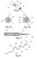
- Figure 9illustrates another variant consisting of a local enhancement of the microprobe by a succession of tubes 70 for, independently of the insulation, consolidate a preform or angulation necessary for the desired function, giving the microprobe a specific shape.
- This solid structurewithout crevices, has the important advantage of being more easily sterilizable compared to conventional probes. The risks of degradation of the microprobe materials due to an overly aggressive sterilization process are thus reduced.
- microprobeintended to be implanted in different sites of the body.
- FIGS. 10a to 10eillustrate an exemplary embodiment of a microprobe according to the invention, intended to be implanted in a vein of the coronary sinus.
- the microprobe represented in Figure 10acomprises a microcable 40 whose sectional view is shown on the Figure 10b .
- the core cable 12 of the microcable 40is formed from composite unitary strands 10, as can be seen in FIG. Figure 10c , a structuring metal core 1, here an MP35N alloy with a diameter of 33 ⁇ m, and an outer envelope 5 ⁇ m thick Pt / Ir 90/10 as radiopaque material 2.
- the ratio between the materialsare 75% for the core and 25% for the outer shell. This simple structure offers good fatigue strength and corrosion resistance guaranteed by platinum.
- a cable 12 with a core of 49 strandsis necessary to obtain an apparent platinum surface of 0.011 mm 2 , sufficient to ensure good visibility under X-ray radiography.
- the conductive core cable 12then has a diameter of 0.30 mm, which which gives it enough flexibility for intravascular use, eg via the coronary sinus.
- the cable 12is covered with an ETFE type insulation layer 25 ⁇ m thick allowing good insulation, compatible with an in-line extrusion process, for a final external diameter of 0.35 mm in the distal part. 103 of the microprobe.
- Apertures 30 forming electrodesare made by laser ablation in the distal portion 103 over an area of 0.5 mm 2 , to minimize the current consumption.
- Heat-shrinkable tubes 51 and 52 of PETare respectively placed in an intermediate zone 102 and in the proximal portion 101, 25 cm and 45 cm from the distal tip 41 of the probe, whose total useful length varies between 90 and 120 cm.
- the proximal portion 101terminates in a transition zone 100 formed by a polyurethane tube 50 connected to a connector 200 of the IS-1 type whose end is provided with a terminal 201 for electrical connection to the implantable equipment generator.
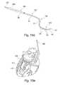
- a method of setting up such a probepresented on the Figure 10e consists in placing the intermediate portion 102 in the coronary sinus and the multi-electrode distal portion 103 in the veins of the coronary network, thereby stimulating the left ventricle VG. This operation is performed using a catheter 300 laying which can be removed by cutting with a cutting tool ( slitter ), as for the establishment of conventional probes.
- FIGS. Figures 11a to 11dA second exemplary embodiment of a microprobe intended to be implanted in a cardiac cavity, for example a straight cavity, is illustrated in FIGS. Figures 11a to 11d .
- This microprobecomprises a microcable 40, a sectional view of which is shown in FIG. Figure 11a .
- the core cable 11 of the microcable 40is formed of composite unitary strands 10, as can be seen in FIG. Figure 11b , a tantalum core 2 as a radiopaque material and an outer shell 2 of structuring material, here nitinol.
- the ratio between materialsis 25% core and 75% for the envelope external.
- This simple structureprovides external elasticity as well as good radiopacity provided by the inner core.
- a core cable 11 of nineteen strandsis necessary to obtain a platinum apparent surface of 0.010 mm 2 , sufficient to ensure good visibility under X-ray fluoroscopy.
- the conductive core cable 11then has a diameter of 0.20 mm, which gives it sufficient flexibility for intra-cavitary use, ventricle and / or right atrium in particular.
- the cable 11is covered with a 25 ⁇ m thick FEP type insulation layer 20 which provides good insulation and is compatible with an in-line extrusion process, for a final external diameter of 0.25 mm in the distal part. of the microprobe.
- a polyimide or PEEK type reinforcing structure of very small thicknessto retain the superelastic properties of nitinol.
- a coating ( coating ) type Carbofilm (registered trademark)with superior resistance to corrosion, and increased biocompatibility.
- This type of coatingless than 1 micron, makes it possible not to modify the electrical properties of the electrode while substantially improving the surface compatibility properties with the blood.
- the probeby appropriate treatment, it is possible to give the probe a configuration that allows it to conform to the heart chamber according to the associated stimulation and anatomy needs.
- the Figures 11c and 11dshow two possible conformations of the probe for stimulation of the right cavities.
- a third embodiment of a microprobe intended to be implanted in the cerebral cavitiesis illustrated on the Figures 12a to 12c .
- the microcable 40 shown on the Figure 12acomprises a core cable 13 formed of composite unitary strands 10 made up, as can be seen in FIG. Figure 12b a tri-layered wire comprising (i) a core 2 of a radio-opaque material, in this case tantalum, (ii) an intermediate layer 1 made of titanium as a structuring material, and (iii) an outer palladium envelope 3 to minimize skin effects and achieve better structural compatibility with MRI.
- the ratio of the three materialsis 30% Ta / 65% Ti / 5% Pd. This structure, although less resistant to fatigue at the strand 10, is compensated by a unit diameter of 16 microns, less mechanically constrained.
- a 133-core core cable 13 (7x19)is necessary to obtain a platinum apparent surface of 0.010 mm 2 , sufficient to ensure good visibility under X-ray radiography.
- the conductive core cable 13then has a diameter of 0.25 mm. , very flexible for intracerebral use.
- the cable 13is covered with a mechanically more flexible FEP-type insulation layer 20 of thickness 25 ⁇ m allowing good insulation and compatible with an in-line extrusion process, for a final external diameter of 0.30. mm in the distal part of the microprobe.
- a polyether block amide Pebax( Trade Mark) may be associated with the isolation layer 20 to manage the stiffness gradients to the proximal portion of the microprobe.
Landscapes
- Health & Medical Sciences (AREA)
- Heart & Thoracic Surgery (AREA)
- Life Sciences & Earth Sciences (AREA)
- Animal Behavior & Ethology (AREA)
- Veterinary Medicine (AREA)
- Public Health (AREA)
- Engineering & Computer Science (AREA)
- Biomedical Technology (AREA)
- General Health & Medical Sciences (AREA)
- Nuclear Medicine, Radiotherapy & Molecular Imaging (AREA)
- Radiology & Medical Imaging (AREA)
- Cardiology (AREA)
- Neurology (AREA)
- Neurosurgery (AREA)
- Psychology (AREA)
- Vascular Medicine (AREA)
- Physics & Mathematics (AREA)
- Biophysics (AREA)
- Pathology (AREA)
- Medical Informatics (AREA)
- Molecular Biology (AREA)
- Surgery (AREA)
- Materials For Medical Uses (AREA)
- Electrotherapy Devices (AREA)
Abstract
Translated fromFrenchDescription
Translated fromFrenchL'invention concerne de façon générale les "dispositifs médicaux implantables actifs" tels que définis par la directive 90/385/CEE du 20 juin 1990 du Conseil des communautés européennes.The invention relates generally to "active implantable medical devices" as defined by Council Directive 90/385 / EEC of 20 June 1990.
Cette définition inclut en particulier les implants cardiaques chargés de surveiller l'activité cardiaque et de générer des impulsions de stimulation, de défibrillation et/ou de resynchronisation en cas de trouble du rythme détecté par l'appareil. Elle inclut aussi les appareils neurologiques, les implants cochléaires, les pompes de diffusion de substances médicales, les capteurs biologiques implantés, etc.This definition includes, in particular, cardiac implants responsible for monitoring cardiac activity and generating pacing, defibrillation and / or resynchronization pulses in the event of a rhythm disorder detected by the device. It also includes neurological devices, cochlear implants, diffusion pumps for medical substances, implanted biological sensors, etc.
Ces dispositifs comportent un boîtier généralement désigné "générateur", raccordé électriquement et mécaniquement à une ou plusieurs "sondes" intracorporelles munie(s) d'électrodes destinées à venir en contact avec les tissus sur lesquels on souhaite appliquer des impulsions de stimulation et/ou recueillir un signal électrique : myocarde, nerf, muscle, ...These devices comprise a housing generally designated "generator", electrically and mechanically connected to one or more intracorporeal "probes" provided with (s) electrodes intended to come into contact with the tissues on which it is desired to apply stimulation pulses and / or collect an electrical signal: myocardium, nerve, muscle, ...
La présente invention concerne plus précisément une microsonde de détection/stimulation destinée à être implantée dans des réseaux veineux, artériels ou lymphatiques.The present invention more specifically relates to a microprobe of detection / stimulation intended to be implanted in venous, arterial or lymphatic networks.
Le principe actuel de stimulation électrique des tissus est basé sur un dispositif, appelé généralement "sonde", qui est un objet implanté au travers de divers vaisseaux, veineux, artériels ou lymphatiques notamment, et dont la fonction est de transmettre un signal électrique au tissu-cible tout en garantissant les propriétés suivantes :
- facilité d'implantation par le médecin dans un réseau de vaisseaux du patient, et en particulier facilité : à faire progresser la sonde dans les vaisseaux par poussée, à faire suivre à la sonde des trajets tortueux et passer des embranchements, et à transmettre des couples ;
- visibilité aux rayons X afin de permettre au médecin une navigation aisée à travers les vaisseaux du réseau sous radioscopie X ;
- atraumaticité de la sonde au niveau des veines, ce qui nécessite une grande souplesse de structure et l'absence de transition rigide ou d'angle vif ;
- aptitude à transmettre un signal électrique aux tissus et à faire des mesures électriques monopolaires ou multipolaires de manière stable ;
- biocompatibilité avec les tissus vivants pour une implantation à long terme ;
- capacité à se connecter à un appareil implantable source de transmission du signal ;
- aptitude à la stérilisation (rayons gamma, température ...) sans subir de dommages;
- biostabilité, en particulier résistance à la corrosion dans le milieu vivant et résistance à la sollicitation mécanique en fatigue liée aux mouvements du patient et des organes ;
- compatibilité avec l'imagerie IRM, particulièrement importante en neurologie.
- ease of implantation by the physician in a network of vessels of the patient, and in particular facilitated: to advance the probe in the vessels by pushing, to follow the probe tortuous paths and pass branch lines, and to transmit couples ;
- X-ray visibility to allow the physician easy navigation through the X-ray network vessels;
- atraumaticity of the probe at the level of the veins, which requires a great flexibility of structure and the absence of rigid transition or sharp angle;
- ability to transmit an electrical signal to tissues and to make monopolar or multipolar electrical measurements in a stable manner;
- biocompatibility with living tissue for long-term implantation;
- ability to connect to an implantable device that is a source of signal transmission;
- ability to sterilize (gamma rays, temperature ...) without being damaged;
- biostability, in particular resistance to corrosion in the living medium and resistance to mechanical stress in fatigue related to the movements of the patient and organs;
- compatibility with MRI imaging, particularly important in neurology.
L'architecture actuelle des sondes répondant à ces besoins peut se résumer à une structure généralement creuse pour permettre le passage d'un mandrin ou d'un fil-guide, et comprenant des composants de type câbles conducteurs isolés, reliés à des électrodes mécaniques pour assurer la conductivité électrique, la radio-opacité ...The current architecture of the probes meeting these needs can be summarized as a generally hollow structure to allow the passage of a mandrel or a guide wire, and comprising insulated conductor cable components connected to mechanical electrodes for ensure electrical conductivity, radio-opacity ...
Il s'agit donc de sondes nécessitant un assemblage complexe d'un nombre important de pièces, de fils et d'isolants associés, créant des risques non négligeables de rupture compte tenu des contraintes mécaniques à long terme auxquelles elles sont exposées.It is therefore probes requiring a complex assembly of a large number of parts, son and associated insulators, creating significant risk of rupture given the long-term mechanical stresses to which they are exposed.
Des exemples de telles sondes sont donnés dans les
Parmi les difficultés rencontrées, on peut citer la gestion des gradients de raideur liés aux pièces mécaniques utilisées, qui affectent fortement les propriétés d'implantabilité et de résistance mécanique sur le long terme (fatigue).Among the difficulties encountered, mention may be made of the management of stiffness gradients related to the mechanical parts used, which strongly affect the implantability and mechanical resistance properties over the long term (fatigue).
De plus, afin d'étanchéifier la lumière interne des sondes, dont l'entrée de sang dégraderait les performances à la pose et à long terme, on utilise des valves et autres dispositifs complexes présentant des risques associés importants.In addition, in order to seal the internal lumen of the probes, the entry of blood degrading the performance at laying and long-term, valves and other complex devices with significant associated risks are used.
D'autres difficultés peuvent également se poser en termes de fatigue des assemblages. En effet, toute zone de transition de rigidité est susceptible d'induire des risques de fatigue, des difficultés à stériliser du fait de la présence de zones d'accès difficile, et des problèmes de tenue des jonctions de conducteurs au niveau de la liaison avec les électrodes et le connecteur.Other difficulties can also arise in terms of assembly fatigue. Indeed, any stiffness transition zone is likely to induce risks of fatigue, difficulties to sterilize due to the presence of difficult access areas, and problems with conducting conductor junctions at the connection with the electrodes and the connector.
Par ailleurs, la tendance clinique dans le domaine des sondes implantables est d'en réduire la taille afin de les rendre moins invasives et plus faciles à manipuler à travers les vaisseaux.In addition, the clinical trend in the field of implantable probes is to reduce their size to make them less invasive and easier to handle through the vessels.
La taille actuelle des sondes implantables est typiquement de l'ordre de 4 à 6 French (1,33 à 2 mm) dans leur partie active, c'est-à-dire la partie la plus distale portant la ou les électrodes - même si le corps de sonde, dans la partie moins distale, utilise des conducteurs de plus faible diamètre, comme par exemple dans le
Cependant, il est clair que la réduction de la taille des sondes augmenterait leur complexité et imposerait des contraintes techniques génératrices de risques.However, it is clear that reducing the size of the probes would increase their complexity and impose technical constraints that generate risks.
Pourtant, une telle réduction, à moins de 2 French (0,66 mm) par exemple, ouvrirait des perspectives d'applications médicales dans des domaines variés allant de la cardiologie à la neurologie en présence d'un réseau veineux, artériel ou même lymphatique, comme le réseau veineux cérébral ou le réseau veineux du sinus coronaire.However, such a reduction, to less than 2 French (0.66 mm) for example, would open perspectives of medical applications in various fields ranging from cardiology to neurology in the presence of a venous, arterial or even lymphatic network. , such as the cerebral venous network or the venous network of the coronary sinus.
Aujourd'hui, la technologie de stimulation électrique a permis des avancées importantes dans le domaine de la neuromodulation, qui consiste à stimuler des zones-cibles du cerveau pour le traitement de la maladie de Parkinson, l'épilepsie et autres maladies neurologiques.Today, electrical stimulation technology has led to significant advances in the field of neuromodulation, which involves stimulating target areas of the brain for the treatment of Parkinson's disease, epilepsy and other neurological diseases.
On pourrait donc imaginer parvenir avec ce type de technologie à traiter de nouvelles régions difficilement atteignables aujourd'hui, ceci au moyen de sondes de stimulation de petite taille, ou "microsondes", présentant une grande robustesse afin de garantir la biostabilité à long terme. Une telle technique permettrait une approche moins invasive de ces traitements et surtout une efficacité supérieure des traitements administrés.One could thus imagine with this type of technology to treat new regions difficult to reach today, this by means of small stimulation probes, or "microworlds", with a great robustness in order to guarantee the long-term biostability. Such a technique would allow a less invasive approach to these treatments and above all a superior efficacy of the treatments administered.
Il serait possible de connecter une ou plusieurs microsondes à travers le réseau de vaisseaux considéré jusqu'à leur localisation-cible. Leur mise en place pourrait être effectuée, du fait de leur taille réduite, par des dispositifs de guidage utilisés aujourd'hui en neuroradiologie interventionnelle pour la libération de ressorts (coils) lors du traitement des anévrismes intracrâniens.It would be possible to connect one or more microwaves across the relevant vessel network to their target location. Their implementation could be carried out, because of their reduced size, by guiding devices used today in interventional neuroradiology for the release of springs (coils ) during the treatment of intracranial aneurysms.
Aussi, le but de la présente invention est de proposer une telle "microsonde" de petite taille qui serait en conformité avec les propriétés générales des sondes implantables telles qu'elles ont été énumérées plus haut, tout en en réduisant la complexité et, de ce fait, le coût final.Also, the object of the present invention is to provide such a small "microprobe" which would be in accordance with the general properties of the implantable probes as enumerated above, while reducing its complexity and, therefore, done, the final cost.
La taille de cette microsonde devrait notamment permettre d'atteindre des veinules de très petites dimensions, inaccessibles aujourd'hui avec des dispositifs de taille supérieure. La microsonde de l'invention devrait également faciliter sensiblement la navigabilité dans les réseaux veineux, artériels ou lymphatiques du fait de sa souplesse, amplifiée par ses petites dimensions.The size of this microprobe should in particular make it possible to reach venules of very small dimensions, inaccessible today with devices of greater size. The microprobe of the invention should also facilitate substantially navigability in the venous, arterial or lymphatic networks because of its flexibility, amplified by its small size.
Conformément à l'invention, ce but est atteint grâce une sonde d'un type général comportant, comme divulgué par le
De façon caractéristique de l'invention, cette sonde est une microsonde constituée dans sa partie active, distale, par ledit microcâble de diamètre au plus égal à 2 French (0,66 mm).In a characteristic manner of the invention, this probe is a microprobe consisting in its active portion, distal, by said microcable with a diameter of at most 2 French (0.66 mm).
A cet effet, le câble de coeur du microcâble possède une structure composite constituée à partir, au moins, dudit matériau structurant et d'un matériau radio-opaque constituant au moins environ 0,008 mm2 de la section du câble de coeur dans une proportion au plus égale à 50%. De plus, au moins une zone dénudée est ménagée dans la couche d'isolement de manière à former au moins une électrode sur une surface totale cumulée au plus égale à 20 mm2. Enfin, des moyens de dégressivité de rigidité sont ménagés le long de la microsonde entre sa partie proximale et sa partie distale.For this purpose, the core cable of the microcable has a composite structure formed from, at least, said structuring material and a radiopaque material constituting at least about 0.008 mm2 of the section of the core cable in a proportion to plus 50%. In addition, at least one stripped zone is formed in the insulation layer so as to form at least one electrode on a cumulative total surface area at most equal to 20 mm2 . Finally, stiffness degressivity means are provided along the microprobe between its proximal portion and its distal portion.
La microsonde peut être rectiligne ou, de préférence, conformée au niveau des électrodes selon au moins une préforme de contact électrique et de stabilisation mécaniqueThe microprobe may be rectilinear or, preferably, shaped at the level of the electrodes according to at least one electrical contact and mechanical stabilization preform
Ainsi, on comprend qu'avec un diamètre ne dépassant pas 0,50 mm, le câble de coeur constituant le microcâble de la microsonde selon l'invention présente une grande flexibilité, favorable à sa manipulation par le médecin, notamment au cours de son implantation lorsqu'il s'agit par exemple de l'introduire dans des réseaux de vaisseaux avec de fortes tortuosités et de nombreux embranchements et d'éviter des traumatismes que pourraient engendrer des sondes beaucoup plus rigides, incompatibles avec les tissus.Thus, it is understood that with a diameter of not more than 0.50 mm, the core cable constituting the microcable of the microprobe according to the invention has great flexibility, favorable to its handling by the doctor, especially during its implantation for example when it involves introducing it into networks of vessels with strong tortuosities and numerous branches and to avoid traumas that could lead to much more rigid probes, incompatible with the tissues.
D'autre part, le choix d'une structure multifilaire toronnée composée de brins très fins, de diamètre unitaire d'au plus 40 µm, de préférence compris entre 20 et 40 µm, permet d'augmenter la résistance à la fatigue mécanique du câble de coeur due aux mouvements du patient et des organes, sachant que la limite de rupture en flexion d'un fil est sensiblement inversement proportionnelle à son diamètre. De manière à renforcer cette importante propriété de biostabilité, il y a avantage à ce que les brins eux-mêmes soient constitués en un matériau structurant dont la résistance à la fatigue intrinsèque est élevée, comme par exemple les matériaux cités plus haut, c'est-à-dire les aciers inox, les alliages de cobalt, le titane et l'alliage NiTi connu notamment sous le nom de nitinol. A ces métaux chargés d'assurer les qualités mécaniques du câble de coeur s'ajoute un matériau radio-opaque destiné à rendre la microsonde visible aux rayons X lors de sa mise en place par le médecin. Le matériau radio-opaque peut être choisi parmi le tantale (Ta), le tungstène (W), l'iridium (Ir), le platine (Pt), l'or (Au) et leurs alliages.On the other hand, the choice of a stranded multifilament structure composed of very fine strands, with a unit diameter of at most 40 μm, preferably between 20 and 40 μm, makes it possible to increase the resistance to mechanical fatigue of the cable. of heart due to the movements of the patient and organs, knowing that the limit of bending rupture of a wire is substantially inversely proportional to its diameter. In order to reinforce this important property of biostability, it is advantageous for the strands themselves to be made of a structuring material whose intrinsic fatigue resistance is high, such as for example the materials mentioned above. that is to say, stainless steels, cobalt alloys, titanium and NiTi alloy known in particular under the name of nitinol. To these metals responsible for ensuring the mechanical properties of the heart cable is added a radiopaque material intended to make the microprobe visible to X-rays when it is put in place by the doctor. The radiopaque material may be selected from tantalum (Ta), tungsten (W), iridium (Ir), platinum (Pt), gold (Au) and their alloys.
Concrètement, l'invention prévoit que la structure composite ainsi obtenue du câble de coeur peut être réalisée par des brins composites constitués, au moins, d'un matériau structurant et d'un matériau radio-opaque, ou par des brins constitués de matériau structurant et des brins constitués de matériau radio-opaque. La pluralité de brins du toron comprend avantageusement entre 15 et 300 brins.Concretely, the invention provides that the composite structure thus obtained of the core cable can be made by composite strands consisting, at least, of a structuring material and a radiopaque material, or by strands consisting of structuring material and strands made of radiopaque material. The plurality of strands of the strand advantageously comprises between 15 and 300 strands.
Pour réaliser le contact électrique avec les tissus et transmettre le signal électrique, l'invention propose donc une solution qui consiste à utiliser le câble de coeur lui-même pour former les électrodes de la microsonde en ménageant des zones dénudées dans une couche d'isolement entourant le câble. L'invention recommande que la couche d'isolement, de préférence en polymère fluoré, ne dépasse pas en épaisseur 30% du diamètre du câble de coeur, ceci dans le but d'éviter l'effet d'escalier en bordure des électrodes qui pourrait nuire au contact électrique avec les tissus. Enfin, les moyens de dégressivité de rigidité (c'est-à-dire qui procurent une rigidité décroissante de la partie proximale vers la partie distale) prévus par l'invention facilitent l'implantation de la microsonde grâce à la faculté qui lui est donnée de pouvoir être poussée à l'intérieur des vaisseaux. Comme on le verra en détail plus loin, les moyens de dégressivité de rigidité peuvent être réalisés, conformément à l'invention, par un empilement étagé de tubes emboîtés les uns dans les autres, ou par une succession de tubes isodiamètre de rigidité croissante.In order to make electrical contact with the tissues and to transmit the electrical signal, the invention proposes a solution which consists in using the heart cable itself to form the electrodes of the microprobe by providing bare areas in an insulation layer surrounding the cable. The invention recommends that the insulation layer, preferably made of fluoropolymer, does not exceed in
La microsonde, une fois en place, est stabilisée en position par préformage, en S ou en spirale à trois dimensions, lequel assure également un contact électrique permanent des électrodes avec les tissus. Avantageusement, la microsonde comprend en outre des moyens de renforcement local.The microprobe, once in place, is stabilized in position by preforming, S or three-dimensional spiral, which also ensures permanent electrical contact of the electrodes with the tissues. Advantageously, the microprobe also comprises local reinforcement means.
Afin de limiter l'échauffement du câble de coeur par effet de peau lors d'une imagerie par IRM, l'invention recommande que les brins comprennent une couche extérieure en matériau à faible susceptibilité magnétique, inférieure à 2 000.10-12.m3.mole-1.In order to limit the heating of the core rope by skin effect in an MRI imaging, the invention recommends that the strands comprise an outer layer of low magnetic susceptibility material, less than 2 .m3 000.10-12. mole-1 .
Le matériau à faible susceptibilité magnétique peut être, au choix, le tantale (Ta), le titane (Ti), le rhodium (Rh), le molybdène (Mo), le tungstène (W), le palladium (Pd), l'or (Au) et leurs alliages.The material with low magnetic susceptibility can be, alternatively, tantalum (Ta), titanium (Ti), rhodium (Rh), molybdenum (Mo), tungsten (W), palladium (Pd), gold (Au) and their alloys.
On va maintenant décrire un exemple de mise en oeuvre du dispositif de l'invention, en référence aux dessins annexés où les mêmes références numériques désignent d'une figure à l'autre des éléments identiques ou fonctionnellement semblables.
- Les
Figures 1a à 1d sont des vues en coupe de brins constitués d'un matériau structurant et d'un matériau radio-opaque. - Les
Figures 2a à 2f sont des vues en coupe de câbles de coeur formés de brins montrés sur lesFigures 1a à 1d . - La
Figure 3 est une vue en coupe d'un câble de coeur formé de brins structurants et de brins radio-opaques. - Les
Figures 4a à 4d sont des vues de côté de préformes de microsondes selon l'invention. - La
Figure 5 est une vue en perspective d'un microcâble présentant une zone totalement dénudée de la couche d'isolement. - La
Figure 6 est une vue en perspective d'un microcâble présentant une zone partiellement dénudée de la couche d'isolement. - Les
Figures 7a et 7b sont des vues en coupe de microcâbles présentant des zones de couche d'isolement partiellement dénudées. - La
Figure 8 est une vue de côté en coupe d'une microsonde présentant un empilement de tubes de gradient de rigidité. - La
Figure 9 est une vue en perspective d'une microsonde munie d'un dispositif de renforcement local. - La
Figure 10a est une vue de côté d'un premier mode de réalisation d'une microsonde conforme à l'invention. - La
Figure 10b est une vue en coupe de la section distale de la microsonde de laFigure 10a . - La
Figure 10c est une vue en coupe d'un brin unitaire du câble de coeur de la microsonde de laFigure 10b . - La
Figure 10d est une vue en perspective de la microsonde de laFigure 10a munie d'un connecteur IS-1. - La
Figure 10e est une vue en perspective montrant une implantation de la microsonde de laFigure 10a dans les veines coronaires. - La
Figure 11a est une vue en coupe d'un deuxième mode de réalisation d'une microsonde conforme à l'invention. - La
Figure 11b est une vue en coupe d'un brin unitaire du câble de coeur de la microsonde de laFigure 11a . - Les
Figures 11c et 11d sont des vues en perspective montrant des implantations de la microsonde de laFigure 11a dans une cavité du coeur. - La
Figure 12a est une vue en coupe d'un troisième mode de réalisation d'une microsonde conforme à l'invention. - La
Figure 12b est une vue en coupe d'un brin unitaire du câble de coeur de la microsonde de laFigure 12a . - La
Figure 12c est une vue en coupe d'un exemple d'implantation de la microsonde de laFigure 12a dans les tissus cérébraux.
- The
Figures 1a to 1d are sectional views of strands consisting of a structuring material and a radiopaque material. - The
Figures 2a to 2f are cross-sectional views of heart cables formed of strands shown on theFigures 1a to 1d . - The
Figure 3 is a sectional view of a core cable formed of structural strands and radiopaque strands. - The
Figures 4a to 4d are side views of microsonde preforms according to the invention. - The
Figure 5 is a perspective view of a microcable having a completely stripped area of the insulation layer. - The
Figure 6 is a perspective view of a microcable having a partially stripped area of the insulation layer. - The
Figures 7a and 7b are sectional views of microcables with partially exposed isolation layer areas. - The
Figure 8 is a sectional side view of a microprobe with a stack of stiffness gradient tubes. - The
Figure 9 is a perspective view of a microprobe with a local reinforcement device. - The
Figure 10a is a side view of a first embodiment of a microprobe according to the invention. - The
Figure 10b is a sectional view of the distal section of the microprobe of theFigure 10a . - The
Figure 10c is a sectional view of a unitary strand of the core cable of the microprobe of theFigure 10b . - The
Figure 10d is a perspective view of the microprobe of theFigure 10a equipped with an IS-1 connector. - The
Figure 10e is a perspective view showing an implantation of the microprobe of theFigure 10a in the coronary veins. - The
Figure 11a is a sectional view of a second embodiment of a microprobe according to the invention. - The
Figure 11b is a sectional view of a unitary strand of the core cable of the microprobe of theFigure 11a . - The
Figures 11c and 11d are perspective views showing implantations of the microprobe of theFigure 11a in a cavity of the heart. - The
Figure 12a is a sectional view of a third embodiment of a microprobe according to the invention. - The
Figure 12b is a sectional view of a unitary strand of the core cable of the microprobe of theFigure 12a . - The
Figure 12c is a sectional view of an example of implantation of the microprobe of theFigure 12a in the brain tissue.
Les sondes concernées par l'invention sont des microsondes de stimulation destinées à être implantées dans des réseaux veineux, artériels ou lymphatiques, et dont le diamètre ne dépasse pas 2 French (0,66 mm). Elles sont constituées dans leur partie active, distale, par un microcâble formé d'un câble de coeur conducteur entouré partiellement d'une couche d'isolement définissant au moins une électrode de stimulation.The probes concerned by the invention are microsondes of stimulation intended to be implanted in venous, arterial or lymphatic networks, and whose diameter does not exceed 2 French (0.66 mm). They are constituted in their active part, distal, by a microcable formed of a conductive core cable partially surrounded by an insulation layer defining at least one stimulation electrode.
La durée de vie est un paramètre fondamental qui doit être absolument pris en compte lors de la conception de tout dispositif médical, en particulier les microsondes de stimulation, objets de l'invention. En effet, les battements du coeur et le mouvement des organes induisent sur ce type de dispositifs des déformations de flexion qui doivent être parfaitement maîtrisées.The service life is a fundamental parameter which must be absolutely taken into account when designing any medical device, in particular the microsondes of stimulation, objects of the invention. Indeed, the beating of the heart and the movement of the organs induce on this type of devices flexural deformations which must be perfectly controlled.
D'une manière générale, pour un fil cylindrique de diamètred, la déformation en flexion peut être caractérisée par le rapport ε =d/D oùD représente le diamètre de la courbure imposée au fil par la contrainte de flexion. Cette contrainte, par exemple liée au battement cardiaque, pourra être subie par le brin sur 400.106 cycles sur une période de 10 ans, engendrant une fatigue du matériau pouvant entraîner sa rupture et limiter sa durée de vie.In general, for a cylindrical wire of diameterd , the bending deformation can be characterized by the ratio ε =d /D whereD represents the diameter of the curvature imposed on the wire by the bending stress. This constraint, for example related to the heartbeat, may be experienced by the strand on 400.106 cycles over a period of 10 years, causing fatigue of the material may cause its rupture and limit its life.
C'est ainsi qu'une microsonde de stimulation par le réseau veineux, par exemple, peut être le siège de déformations de courbure supérieures à une sonde normale dans la mesure où elle doit suivre les déformations des veines, ce qui provoque une contrainte plus importante et rend sa résistance à la fatigue plus contraignante.Thus a microprobe of stimulation by the venous network, for example, can be the seat of deformations of curvature superior to a normal probe insofar as it must follow the deformations of the veins, which causes a greater stress and makes its resistance to fatigue more restrictive.
Pour augmenter la limite de rupture à la fatigue des microsondes, il y a donc avantage à adopter pour le câble de coeur une structure multifilaire sous la forme d'un toron d'une pluralité de brins conducteurs de faible diamètred. La réduction en diamètre des brins unitaires permet en effet de réduire la contrainte appliquée à chacun d'entre eux et donc d'augmenter les performances en fatigue de la structure du toron. Pour un matériau donné, il est possible de définir une déformation maximale εMax correspondant à sa limite de résistance à la fatigue pour un nombre de cycles de déformation égal par exemple à 100.106.To increase the fatigue rupture limit of the microworlds, it is therefore advantageous to adopt for the core cable a multiwire structure in the form of a strand of a plurality of conductive strands of small diameterd . The reduction in diameter of the unitary strands makes it possible reduce the stress applied to each of them and therefore increase the fatigue performance of the strand structure. For a given material, it is possible to define a maximum deformation εMax corresponding to its fatigue strength limit for a number of deformation cycles equal, for example, to 100 × 106 .
Le choix d'un matériau constituant l'armature du câble de coeur, qu'on appellera "matériau structurant", doit répondre à plusieurs critères.The choice of a material constituting the frame of the core cable, which will be called "structuring material", must meet several criteria.
Il doit notamment faire partie des matériaux dont les propriétés mécaniques sont connus pour des applications implantables à long terme et présenter une déformation maximale εMax supérieure à la déformation qu'un brin est susceptible de subir, tout en restant compatible avec la faisabilité technique et le coût d'un brin de très faible diamètre.It must in particular be part of materials whose mechanical properties are known for long-term implantable applications and have a maximum deformation εMax greater than the deformation that a strand is likely to undergo, while remaining compatible with the technical feasibility and the cost of a strand of very small diameter.
A titre d'exemple, pour un alliage de cobalt de type MP35N ayant une déformation maximale εMax de 5.10-3 à 100.106 cycles et pour un diamètre de courbureD de 7 mm, le diamètre du brin unitaire devra être inférieur à 35 µm. Un brin de 20 µm résistera donc facilement à cette sollicitation, tandis qu'un brin de 40 µm risquera d'engendrer une rupture avant d'atteindre les 100.106 cycles. A noter que les alliages NiTi présentent de déformation maximale εMax supérieure, de 5 à 9.10-3, offrant des possibilités encore plus larges.By way of example, for a cobalt alloy of the MP35N type having a maximum deformation εMax of 5.10-3 to 100.106 cycles and for a diameter of curvatureD of 7 mm, the diameter of the unit strand must be less than 35 μm. . A strand of 20 microns will easily resist this stress, while a strand of 40 microns may cause a break before reaching the 100.106 cycles. It should be noted that the NiTi alloys exhibit maximum deformation εMax greater, from 5 to 9.10-3 , offering even wider possibilities.
En résumé, il est proposé par l'invention d'utiliser pour matériau structurant un acier inox, un alliage de cobalt de la série MP35N, un métal précieux, du titane ou un alliage NiTi, de résistance à la fatigue élevée, pour former une structure multifilaire dont le diamètred des brins n'excède pas 40 µm, cette dimension permettant en moyenne de garantir une résistance à la rupture en fatigue maximale dans les conditions extrêmes de contrainte auxquelles de telles structures peuvent être soumises.In summary, it is proposed by the invention to use as structuring material a stainless steel, a cobalt alloy of the MP35N series, a precious metal, titanium or a NiTi alloy, of high fatigue resistance, to form a multi-filament structure whose strands have a diameterof not more than 40 μm, this dimension allowing on average to guarantee a maximum fatigue rupture strength under the extreme stress conditions to which such structures may be subjected.
On considèrera idéalement des brins de diamètred compris entre 20 et 40 µm, des dimensions inférieures pouvant poser des problèmes de faisabilité technique et de coût.Ideally, strands with a diameterof between 20 and 40 μm will be considered, with smaller dimensions that may pose problems of technical feasibility and cost.
Afin de garantir une visibilité aux rayons X suffisante pour l'implantation de la microsonde, il est nécessaire d'introduire le long du câble de coeur une quantité minimale de matériau radio-opaque.In order to guarantee sufficient X-ray visibility for the implantation of the microprobe, it is necessary to introduce a minimum quantity of radio-opaque material along the core cable.
La difficulté à cet égard est de concilier la résistance à la fatigue du câble avec la radio-opacité ainsi que la résistance à la corrosion. En effet, la plupart des matériaux utilisés pour leur visibilité aux rayons X, à savoir le tantale (Ta), le tungstène (W), l'iridium (Ir), le platine (Pt), l'or (Au) et leurs alliages, ne présentent pas en général une grande résistance à la fatigue. C'est pourquoi il y a avantage à adopter dans ce cas une structure de câble dite composite dans laquelle un matériau radio-opaque est ajouté au matériau structurant au sein du toron de brins unitaires.The difficulty in this respect is to reconcile the fatigue resistance of the cable with the radiopacity as well as the resistance to corrosion. Indeed, the most materials used for their X-ray visibility, namely tantalum (Ta), tungsten (W), iridium (Ir), platinum (Pt), gold (Au) and their alloys, do not present not generally a great resistance to fatigue. This is why it is advantageous to adopt in this case a so-called composite cable structure in which a radiopaque material is added to the structuring material within the strand of single strands.
Compte tenu de la sensibilité des équipements de radioscopie X actuels, on estime la présence minimale de matériau radio-opaque dans la structure composite à une surface de 0,008 mm2 dans la section du câble de coeur, sans toutefois que la proportion de matériau radio-opaque ne dépasse 50%, ceci afin de ne pas dégrader les propriétés mécaniques des brins assurées par le matériau structurant.Given the sensitivity of current X-ray equipment, the minimum presence of radiopaque material in the composite structure is estimated to be 0.008 mm2 in the section of the core cable, but the proportion of radiopaque material opaque does not exceed 50%, in order not to degrade the mechanical properties of the strands ensured by the structuring material.
Comme le montrent les
Les brins 10 ainsi obtenus peuvent être toronnés pour constituer un câble de coeur pour la microsonde. Sur la
Selon la variante de la
S'agissant du nombre de brins par toron, on peut calculer que pour un diamètre de brins de 40 µm et une proportion de matériau radio-opaque de 50% occupant une section de 0,008 mm2, le nombre total de brins tous matériaux confondus est de l'ordre de quinze brins. A l'inverse, pour un diamètre de brin de 15 µm et une proportion de matériau radio-opaque de 15% occupant la même section, le nombre total de brins atteint environ 300 brins.As regards the number of strands per strand, it can be calculated that for a diameter of strands of 40 μm and a proportion of radio-opaque material of 50% occupying a section of 0.008 mm2 , the total number of strands of all materials combined is of the order of fifteen strands. Conversely, for a strand diameter of 15 μm and a proportion of radiopaque material of 15% occupying the same section, the total number of strands reaches about 300 strands.
Une autre caractéristique physique importante pour une microsonde est sa flexibilité. C'est cette propriété en effet qui permet au dispositif de stimulation de traverser les tortuosités de faible rayon et de garantir l'absence de traumaticité de la sonde en évitant de perforer les veines dans lesquelles elle circule. Pour garantir l'atraumaticité, l'extrémité de la microsonde sera arrondie en demi-sphère afin de minimiser ce risque de perforation.Another important physical feature for a microprobe is its flexibility. It is this property in fact which allows the stimulation device to cross the tortuosities of small radius and to guarantee the absence of traumaticity of the probe by avoiding perforating the veins in which it circulates. To ensure atraumaticity, the end of the microprobe will be rounded half-sphere to minimize this risk of perforation.
En effectuant une comparaison avec les fils-guides existants utilisés dans les mêmes applications, la Demanderesse a pu établir qu'un diamètre externe du câble de coeur au plus égal à 0,50 mm permet d'obtenir un niveau suffisant de flexibilité et de compatibilité avec les tissus vivants. D'une manière générale, la compatibilité des dispositifs implantables avec les techniques médicales modernes d'imagerie, telles que l'IRM, est fondamentale pour garantir un traitement optimal du patient.Comparing with the existing guidewires used in the same applications, the Applicant has been able to establish that an outer diameter of the core cable at most equal to 0.50 mm provides a sufficient level of flexibility and compatibility. with living tissues. In general, the compatibility of implantable devices with modern medical imaging techniques, such as MRI, is fundamental to ensuring optimal patient care.
En effet, du fait de sa structure globalement métallique, la microsonde présente un risque d'échauffement lié aux courants induits par "effet de peau" à l'extérieur des brins unitaires sous l'action du champ magnétique appliqué. Le faible diamètre donné aux brins est toutefois favorable à la dissipation thermique et réduit les effets d'échauffement dus à l'IRM. De plus, l'énergie thermique emmagasinée par les matériaux, déjà limitée en volume, peut encore être diminuée si les brins unitaires sont revêtus d'une couche extérieure en matériau à faible susceptibilité magnétique (la susceptibilité magnétique étant la faculté d'un matériau à s'aimanter sous l'action d'un champ magnétique extérieur).Indeed, because of its overall metallic structure, the microprobe has a risk of heating related to currents induced by "skin effect" outside the unit strands under the action of the applied magnetic field. The small diameter given to the strands, however, is favorable to heat dissipation and reduces the heating effects due to MRI. In addition, the thermal energy stored by the materials, already limited in volume, can be further reduced if the unitary strands are coated with an outer layer of low magnetic susceptibility material (the magnetic susceptibility being the faculty of a material to to be magnetized under the action of an external magnetic field).
Les matériaux les plus favorables dans cette application sont ceux dont la susceptibilité magnétique est inférieure à 2 000.10-12 m3.mole-1, notamment le tantale (Ta), le titane (Ti), le rhodium (Rh), le molybdène (Mo), le tungstène (W), le palladium (Pd), l'or (Au) et leurs alliages.The most favorable materials in this application are those whose magnetic susceptibility is less than 2 000 × 10-12 m3 · mol-1 , especially tantalum (Ta), titanium (Ti), rhodium (Rh), molybdenum ( Mo), tungsten (W), palladium (Pd), gold (Au) and their alloys.
Concernant la transmission du courant électrique aux tissus, le concept retenu par l'invention est de ne pas prévoir d'électrodes rapportées, mais, comme le montre la
La couche 20 d'isolement couvre l'ensemble de la structure conductrice du câble 11 de coeur, sauf au niveau des zones d'électrode réparties le long du microcâble ainsi réalisé.The
De préférence, l'épaisseur de la couche 20 d'isolement n'excède pas 30% du diamètre extérieur du câble 11 de coeur, ceci pour éviter l'effet d'escalier en bordure d'électrode, l'isolant pouvant empêcher le contact de l'électrode avec le tissu.Preferably, the thickness of the
Les caractéristiques requises pour la couche 20 d'isolement sont les suivantes :
- résistance à la fatigue,
- isolement électrique,
- biocompatibilité à long terme,
- biostabilité,
- possibilité de transformation et mise en oeuvre compatible avec le conducteur du câble de coeur.
- fatigue resistance,
- electrical isolation,
- long-term biocompatibility,
- biostability,
- possibility of transformation and implementation compatible with the conductor of the heart cable.
Les matériaux pouvant être utilisés dans ce cadre sont, par exemple :
- les polyuréthannes (PU),
- les polyesters (PET),
- les polyamides (PA),
- les polycarbonates (PC),
- les polyimides,
- les polymères fluorés,
- le polyéther-éther-kétone (PEEK),
- le poly-p-xylylène (parylène),
- le polyméthacrylate de méthyle (PMM).
- polyurethanes (PU),
- polyesters (PET),
- polyamides (PA),
- polycarbonates (PC),
- polyimides,
- fluorinated polymers,
- polyether ether ketone (PEEK),
- poly-p-xylylene (parylene),
- polymethyl methacrylate (PMM).
Cependant, on privilégiera les matériaux à forte inertie chimique comme les polymères fluorés, qui présentent également une très bonne qualité d'isolation. Parmi ces composés, on peut citer :
- le PTFE (polytétrafluoroéthylène),
- le FEP (propylène perfluoré),
- le PFA (résine de copolymère perfluoroalkoxy),
- le THV (tétrafluoroéthylène, hexafluoropropylène, fluorure de vinylidène),
- le PVDF (polyfluorure de vinylidène),
- l'EFEP (éthylène propylène éthylène fluoré),
- l'ETFE (éthylène tétrafluoroéthylène).
- PTFE (polytetrafluoroethylene),
- FEP (perfluorinated propylene),
- PFA (perfluoroalkoxy copolymer resin),
- THV (tetrafluoroethylene, hexafluoropropylene, vinylidene fluoride),
- PVDF (polyvinylidene fluoride),
- EFEP (ethylene propylene fluorinated ethylene),
- ETFE (ethylene tetrafluoroethylene).
Les procédés de réalisation de la couche d'isolement sur le câble de coeur sont multiples en fonction des matériaux utilisés :
- co-extrusion sur le conducteur, pour PU, PA, PEEK, polyimides et polymères fluorés ;
- dépôt par trempage dans une solution, pour PU, PA et polyimides ;
- échauffement d'un tube thermorétractable, pour PET et polymères fluorés ;
- dépôt chimique par voie gazeuse, pour le parylène ;
- traitements plasma pour améliorer l'adhésion entre les couches.
- co-extrusion on the conductor, for PU, PA, PEEK, polyimides and fluoropolymers;
- dip deposit in a solution, for PU, PA and polyimides;
- heating of a heat-shrinkable tube, for PET and fluoropolymers;
- chemical deposition by gaseous route for parylene;
- plasma treatments to improve adhesion between layers.
Lors de la mise en oeuvre de ces procédés, les zones d'électrode peuvent être définies en déposant des couches d'isolement séparées les unes des autres, ou par dénudage partiel d'une couche d'isolement déposée sur la totalité du câble. Ce dénudage est effectué par exemple par ablation laser. Comme l'indiquent les
Avantageusement, les zones d'électrode réparties le long du microcâble présentent une surface cumulée ne dépassant pas 20 mm2, par exemple sous la forme de 40 électrodes de 0,5 mm2 ou 20 électrodes de 1 mm2, cette surface dépendant de l'application ainsi que des performances électriques de l'équipement associé.Advantageously, the electrode zones distributed along the microcable have a cumulative area not exceeding 20 mm2 , for example in the form of 40 electrodes of 0.5 mm2 or 20 electrodes of 1 mm2 , this surface depending on the application as well as electrical performance of the associated equipment.
Idéalement, afin de limiter la consommation de courant, il est cependant préférable de réaliser des électrodes d'une surface au plus égale à 0,5 mm2, en augmentant ainsi la densité de courant locale.Ideally, in order to limit current consumption, it is however preferable to produce electrodes with a surface area at most equal to 0.5 mm2 , thus increasing the local current density.
Si cela s'avère nécessaire, le microcâble peut comporter au niveau des électrodes un renforcement de résistance à la corrosion, obtenu par ajout d'un revêtement dédié à très forte résistance. La résistance à la corrosion peut également résulter du choix d'une structure où le métal noble du matériau radio-opaque forme une couche extérieure gainant un coeur de matériau structurant.If this proves necessary, the microcable can comprise at the level of the electrodes a reinforcement of resistance to corrosion, obtained by adding a dedicated coating with very strong resistance. The corrosion resistance can also result from the choice of a structure where the noble metal of the radiopaque material forms an outer layer sheathing a core of structuring material.
Une première technologie utilisée en ce sens consiste en un dépôt submicronique (inférieur à 1 µm) par voie chimique ou électrochimique d'un matériau noble, du type de ceux mentionnés plus haut comme matériaux radio-opaques.A first technology used in this sense is a submicron deposition (less than 1 micron) chemically or electrochemically of a noble material, of the type mentioned above as radio-opaque materials.
Une autre technique consiste à réaliser un tube composite de type DFT (Drawn Filled Tube), avec une couche supplémentaire de 1 à 2 µm de métal noble.Another technique consists in producing a DFT (Drawn Filled Tube ) type composite tube with an additional layer of 1 to 2 μm of noble metal.
Une autre méthode encore consiste à réaliser un dépôt de carbone de typeCarbofilm (marque déposée) permettant d'obtenir une protection anticorrosion et de bonnes performances en termes d'hémocompatibilité et de biocompatibilité.Yet another method consists in producing a carbon deposit of theCarbofilm (registered trademark) type whichmakes it possible to obtain corrosion protection and good performance in terms of hemocompatibility and biocompatibility.
Au besoin, la surface externe de la couche d'isolement proche des électrodes peut contenir un anti-inflammatoire de type stéroïde. Dans ce cas, une très fine couche de stéroïde est déposée en fin de processus de fabrication par un procédé de greffage chimique ou par réticulation de polymère, par exemple un polymère biodégradable de type PLAGA (acide polylactique co-glycolique) ou PLA (acide polylactique).If necessary, the outer surface of the insulating layer near the electrodes may contain a steroidal anti-inflammatory. In this case, a very thin steroid layer is deposited at the end of the manufacturing process by a chemical grafting or polymer crosslinking process, for example a biodegradable polymer of the PLAGA (co-glycolic polylactic acid) or PLA (polylactic acid) type. ).
On peut également envisager que le produit anti-inflammatoire soit contenu dans le matériau constituant la couche d'isolement.It can also be envisaged that the anti-inflammatory product is contained in the material constituting the isolation layer.
Enfin, la microsonde est terminée à partie proximale par un connecteur prévu pour être raccordé au générateur de l'appareil implantable.Finally, the microprobe is terminated proximally by a connector intended to be connected to the generator of the implantable device.
Selon un aspect particulièrement avantageux de l'invention, du fait de la petite taille de la microsonde, il est envisagé de préformer celle-ci au niveau des électrodes afin de favoriser le contact électrique avec les tissus, et également afin de stabiliser mécaniquement la microsonde dans les vaisseaux.According to a particularly advantageous aspect of the invention, because of the small size of the microprobe, it is envisaged to preform it at the electrodes to promote electrical contact with the tissues, and also to mechanically stabilize the microworld in the ships.
Les préformes pourront être obtenues par formage de la partie métallique ou polymère de la sonde, par exemple par traitement thermique.The preforms may be obtained by forming the metal or polymer part of the probe, for example by heat treatment.
Les
Selon un autre aspect de l'invention, une caractéristique déterminante d'une microsonde est de pouvoir être aisément manipulable par le médecin lors de l'implantation.According to another aspect of the invention, a defining characteristic of a microprobe is that it can be easily manipulated by the physician during implantation.
Il est également important de minimiser les transitions de rigidité le long de la sonde de manière à réduire les concentrations de contrainte pouvant conduire à des fragilisations en fatigue du dispositif. Néanmoins, une certaine rigidification est nécessaire car une microsonde excessivement souple limiterait la manipulation en poussée.It is also important to minimize the stiffness transitions along the probe so as to reduce the stress concentrations that can lead to fatigue embrittlement of the device. Nevertheless, a certain stiffening is necessary because an excessively flexible microprobe would limit the manipulation in thrust.
La solution à ces difficultés consiste en une rigidification étagée, rendue possible par des moyens de dégressivité de rigidité ménagés entre la partie proximale et la partie distale de la microsonde. Il est alors possible de gérer le gradient de rigidité progressif le long de la sonde de manière à garantir, d'une part, une partie distale souple non traumatique permettant de passer au travers des tortuosités et, d'autre part, une partie proximale plus rigide permettant de transmettre la poussée exercée par le médecin au moyen de dispositifs appropriés.The solution to these difficulties consists of a stepped stiffening made possible by means of degression of stiffness provided between the proximal portion and the distal portion of the microprobe. It is then possible to manage the progressive stiffness gradient along the probe so as to ensure, on the one hand, a non-traumatic soft distal part allowing to pass through the tortuosities and, on the other hand, a proximal part more rigid device for transmitting the thrust exerted by the physician by means of appropriate devices.
Dans l'exemple proposé à la
Ainsi, la rigidité en extrémité proximale de la sonde peut être cinquante fois supérieure à la rigidité en extrémité distale, sans que cela nécessite d'ajouter de pièce mécanique supplémentaire. La robustesse de l'ensemble est également fortement accrue.Thus, the rigidity at the proximal end of the probe can be fifty times greater than the stiffness at the distal end, without this requiring the addition of additional mechanical part. The robustness of the whole is also greatly increased.
On peut aussi envisager des moyens de dégressivité de rigidité réalisés par une succession de tubes isodiamètre de rigidité décroissante, soudés entre eux. Toutefois, cette technique génère des risques de rupture au niveau des soudures entre les tubes.It is also possible to envisage means of degression of rigidity realized by a succession of isodiameter tubes of decreasing rigidity, welded together. However, this technique generates risks of rupture in the welds between the tubes.
Enfin, la
Cette structure pleine, sans anfractuosités, présente l'avantage important d'être plus facilement stérilisable en comparaison des sondes classiques. Sont ainsi réduits les risques de dégradation des matériaux de la microsonde dus à un procédé de stérilisation trop agressif.This solid structure, without crevices, has the important advantage of being more easily sterilizable compared to conventional probes. The risks of degradation of the microprobe materials due to an overly aggressive sterilization process are thus reduced.
On va maintenant décrire des exemples particuliers de réalisation d'une microsonde selon l'invention, destinés à être implantées dans différents sites du corps.We will now describe particular embodiments of a microprobe according to the invention, intended to be implanted in different sites of the body.
Les
La microsonde représentée à la
Un câble 12 avec un coeur de 49 brins est nécessaire pour obtenir une surface apparente de platine de 0,011 mm2, suffisante pour assurer une bonne visibilité sous radioscopie X. Le câble 12 de coeur conducteur a alors un diamètre de 0,30 mm, ce qui lui confère suffisamment de souplesse pour une utilisation intravasculaire, via le sinus coronaire par exemple.A
Le câble 12 est recouvert d'une couche 20 d'isolement de type ETFE d'épaisseur 25 µm permettant une bonne isolation, compatible avec un procédé d'extrusion en ligne, pour un diamètre externe final de 0,35 mm dans la partie distale 103 de la microsonde.The
Des ouvertures 30 formant électrodes sont réalisées par ablation laser dans la partie distale 103 sur une surface de 0,5 mm2, permettant de réduire au maximum la consommation de courant.
Des tubes thermorétractables 51 et 52 en PET sont respectivement placés dans une zone intermédiaire 102 et en partie proximale 101, à 25 cm et 45 cm de la pointe distale 41 de la sonde, dont la longueur totale utile varie entre 90 et 120 cm.Heat-
La structure complète de la microsonde est donnée à la
Un procédé de mise en place d'une telle sonde, présenté sur la
Un deuxième exemple de réalisation d'une microsonde destinée à être implantée dans une cavité cardiaque, par exemple une cavité droite, est illustré sur les
Cette microsonde comprend un microcâble 40 dont une vue en coupe est montrée sur la
Il faut rappeler l'avantage du nitinol de présenter une mémoire de forme importante, particulièrement favorable au contact dans une cavité de grande taille.It should be remembered the advantage of nitinol to have a large memory shape, particularly favorable to contact in a large cavity.
Un câble de coeur 11 de dix-neuf brins est nécessaire pour obtenir une surface apparente de platine de 0,010 mm2, suffisante pour assurer une bonne visibilité sous radioscopie X. Le câble de coeur 11 conducteur a alors un diamètre de 0,20 mm, ce qui lui confère suffisamment de souplesse pour une utilisation intra-cavitaire, ventricule et/ou oreillette droite en particulier.A
Le câble 11 est recouvert d'une couche 20 d'isolement de type FEP d'épaisseur 25 µm permettant une bonne isolation et compatible avec un procédé d'extrusion en ligne, pour un diamètre externe final de 0,25 mm dans la partie distale de la microsonde.The
Dans cet exemple de réalisation, il est possible d'utiliser une structure de renfort de type Polyimide ou PEEK de très faible épaisseur permettant de conserver les propriétés superélastiques du nitinol. On appliquera dans ce cas sur l'ensemble du microcâble un revêtement (coating) de typeCarbofilm (marque déposée) présentant une résistance supérieure à la corrosion, ainsi qu'une biocompatibilité accrue. Ce type de revêtement, inférieur à 1 µm, permet de ne pas modifier les propriétés électriques de l'électrode tout en améliorant sensiblement les propriétés de compatibilité en surface avec le sang.In this embodiment, it is possible to use a polyimide or PEEK type reinforcing structure of very small thickness to retain the superelastic properties of nitinol. In this case it will be applied to the entire microcable a coating (coating ) typeCarbofilm (registered trademark) with superior resistance to corrosion, and increased biocompatibility. This type of coating, less than 1 micron, makes it possible not to modify the electrical properties of the electrode while substantially improving the surface compatibility properties with the blood.
De plus, par un traitement approprié, il est possible de donner à la sonde une configuration lui permettant de se conformer à la cavité cardiaque en fonction des besoins de stimulation et d'anatomie associés. Les
Un troisième exemple de réalisation d'une microsonde destinée à être implantée dans les cavités cérébrales est illustré sur les
Dans cet exemple, une très bonne radio-opacité est nécessaire, ainsi qu'une grande souplesse et un diamètre très faible. D'autre part, pour ce type de produit, la compatibilité IRM est fondamentale.In this example, very good radiopacity is required, as well as great flexibility and a very small diameter. On the other hand, for this type of product, MRI compatibility is fundamental.
Le microcâble 40 montré sur la
Un câble 13 de coeur de 133 brins (7x19) est nécessaire pour obtenir une surface apparente de platine de 0,010 mm2, suffisante pour assurer une bonne visibilité sous radioscopie X. Le câble de coeur conducteur 13 a alors un diamètre de 0,25 mm, très souple pour une utilisation intracérébrale.A 133-core core cable 13 (7x19) is necessary to obtain a platinum apparent surface of 0.010 mm2 , sufficient to ensure good visibility under X-ray radiography. The
Le câble 13 est recouvert d'une couche 20 d'isolement de type FEP, mécaniquement plus souple, d'épaisseur 25 µm permettant une bonne isolation et compatible avec un procédé d'extrusion en ligne, pour un diamètre externe final de 0,30 mm dans la partie distale de la microsonde.The
Un polyéther bloc amidePebax (marque déposée) peut être associé à la couche 20 d'isolement pour gérer les gradients de rigidité vers la partie proximale de la microsonde.A polyether block amidePebax (Trade Mark) may be associated with the
Un exemple d'implantation de cette sonde est montré sur la
Claims (20)
Translated fromFrenchce câble de coeur comprenant un matériau structurant (1) présentant une résistance à la fatigue élevée ; et
said core cable comprising a structuring material (1) having a high fatigue resistance; and
Priority Applications (1)
| Application Number | Priority Date | Filing Date | Title |
|---|---|---|---|
| EP22160463.0AEP4043065A1 (en) | 2011-10-14 | 2012-10-02 | Detection/stimulation microprobe implantable in venous, arterial or lymphatic systems |
Applications Claiming Priority (1)
| Application Number | Priority Date | Filing Date | Title |
|---|---|---|---|
| FR1159321 | 2011-10-14 |
Related Child Applications (1)
| Application Number | Title | Priority Date | Filing Date |
|---|---|---|---|
| EP22160463.0ADivisionEP4043065A1 (en) | 2011-10-14 | 2012-10-02 | Detection/stimulation microprobe implantable in venous, arterial or lymphatic systems |
Publications (1)
| Publication Number | Publication Date |
|---|---|
| EP2581107A1true EP2581107A1 (en) | 2013-04-17 |
Family
ID=46924368
Family Applications (2)
| Application Number | Title | Priority Date | Filing Date |
|---|---|---|---|
| EP12187052.1ACeasedEP2581107A1 (en) | 2011-10-14 | 2012-10-02 | Detection/stimulation microprobe implantable in venous, arterial or lymphatic networks |
| EP22160463.0APendingEP4043065A1 (en) | 2011-10-14 | 2012-10-02 | Detection/stimulation microprobe implantable in venous, arterial or lymphatic systems |
Family Applications After (1)
| Application Number | Title | Priority Date | Filing Date |
|---|---|---|---|
| EP22160463.0APendingEP4043065A1 (en) | 2011-10-14 | 2012-10-02 | Detection/stimulation microprobe implantable in venous, arterial or lymphatic systems |
Country Status (3)
| Country | Link |
|---|---|
| US (2) | US8868213B2 (en) |
| EP (2) | EP2581107A1 (en) |
| CN (1) | CN103143114B (en) |
Cited By (9)
| Publication number | Priority date | Publication date | Assignee | Title |
|---|---|---|---|---|
| EP2810686A1 (en) | 2013-06-04 | 2014-12-10 | Sorin CRM SAS | Assembly suitable for implantation in the coronary venous network for stimulation of a left heart chamber |
| FR3006594A1 (en)* | 2013-06-11 | 2014-12-12 | Sorin Crm Sas | IMPLANTABLE MICROSONDE FOR DETECTION / STIMULATION INCORPORATING AN ANTI-INFLAMMATORY AGENT |
| EP2878332A1 (en) | 2013-11-27 | 2015-06-03 | Sorin CRM SAS | Detection/stimulation microprobe implantable in a vessel of the venous, lymphatic or arterial network |
| EP2959828A1 (en) | 2014-06-25 | 2015-12-30 | Sorin CRM SAS | Hybrid assembly forming an active implantable medical device |
| EP3058983A1 (en) | 2015-02-17 | 2016-08-24 | Sorin CRM SAS | Detection/stimulation microprobe, in particular for multipoint neuromodulation of the central nervous system |
| EP3069755A1 (en) | 2015-03-18 | 2016-09-21 | Sorin CRM SAS | Active implantable medical device comprising a connector-free capsule, permanently connected to a microprobe |
| WO2017158174A1 (en) | 2016-03-18 | 2017-09-21 | Sorin Crm Sas | Active implantable medical device for combined treatment of cardiac rhythm and of respiratory rhythm |
| WO2017198472A1 (en) | 2016-05-19 | 2017-11-23 | Sorin Crm Sas | Dual multipolar lead implantable in the coronary venous network |
| EP3591763A1 (en) | 2018-07-06 | 2020-01-08 | Sorin CRM SAS | Connection method for connecting an insulated micro-conductor |
Families Citing this family (18)
| Publication number | Priority date | Publication date | Assignee | Title |
|---|---|---|---|---|
| JP2017538563A (en)* | 2014-11-09 | 2017-12-28 | センソ メディカル ラボ リミテッド | Three-dimensional custom formation of surgical guide |
| US9855415B2 (en)* | 2015-07-25 | 2018-01-02 | Cardiac Pacemakers, Inc. | Medical electrical lead with biostable PVDF-based materials |
| US11554250B2 (en)* | 2016-10-18 | 2023-01-17 | Merit Medical Systems, Inc. | Single and multilayer bands and related methods |
| EP3538207B1 (en) | 2016-11-08 | 2023-10-18 | Advanced Bionics AG | Electrode arrays and cochlear implants including the same |
| CN116688353A (en) | 2016-12-01 | 2023-09-05 | 领先仿生公司 | Contact array assembly, cochlear implant, and method of forming cochlear implant electrode array |
| US10688308B2 (en) | 2016-12-12 | 2020-06-23 | Sorin Crm Sas | System and method for extra cardiac defibrillation |
| US10485981B2 (en)* | 2016-12-27 | 2019-11-26 | Cardiac Pacemakers, Inc. | Fixation methods for leadless cardiac devices |
| US12195916B2 (en) | 2017-03-31 | 2025-01-14 | Fort Wayne Metals Research Products, Llc | Small diameter cable |
| EP3415651A1 (en)* | 2017-06-14 | 2018-12-19 | Heraeus Deutschland GmbH & Co. KG | A method for manufacturing a passivated product |
| EP3415649B1 (en)* | 2017-06-14 | 2022-08-03 | Heraeus Deutschland GmbH & Co. KG | A composite wire |
| JP2020089723A (en)* | 2018-12-07 | 2020-06-11 | アヴェント インコーポレイテッド | Device and method for selectively and reversibly modulating nervous system structure to inhibit perception of pain |
| WO2021062480A1 (en)* | 2019-10-04 | 2021-04-08 | Saluda Medical Pty Limited | Lead for an active implantable medical device |
| CN111214284B (en)* | 2020-01-21 | 2022-07-05 | 沪创医疗科技(上海)有限公司 | Degradable metal cable internal fixing system and application |
| US11697869B2 (en) | 2020-01-22 | 2023-07-11 | Heraeus Deutschland GmbH & Co. KG | Method for manufacturing a biocompatible wire |
| DE102020207093B3 (en)* | 2020-06-05 | 2021-08-26 | Fraunhofer-Gesellschaft zur Förderung der angewandten Forschung eingetragener Verein | Electrically conductive connecting element for a temporary electrically conductive connection to an electrical consumer |
| WO2022109550A1 (en)* | 2020-11-17 | 2022-05-27 | Robert Dittmer | Wire electrodes for use in wearable devices |
| US11794002B2 (en) | 2020-12-15 | 2023-10-24 | Industrial Technology Research Institute | Neuromodulation probe |
| TWI792518B (en)* | 2020-12-15 | 2023-02-11 | 財團法人工業技術研究院 | Neuromodulation probe |
Citations (10)
| Publication number | Priority date | Publication date | Assignee | Title |
|---|---|---|---|---|
| US5246014A (en) | 1991-11-08 | 1993-09-21 | Medtronic, Inc. | Implantable lead system |
| US6192280B1 (en) | 1999-06-02 | 2001-02-20 | Medtronic, Inc. | Guidewire placed implantable lead with tip seal |
| WO2005081681A2 (en)* | 2004-02-11 | 2005-09-09 | Fort Wayne Metals Research Products Corporation | Drawn strand filled tubing wire |
| US7047082B1 (en) | 1999-09-16 | 2006-05-16 | Micronet Medical, Inc. | Neurostimulating lead |
| US20060247751A1 (en)* | 2005-04-28 | 2006-11-02 | Seifert Kevin R | Guide catheters for accessing cardiac sites |
| US20070225784A1 (en)* | 2006-03-23 | 2007-09-27 | Cardiac Pacemakers, Inc. | Medical lead having a variable change in stiffness |
| US20090157136A1 (en)* | 2007-02-16 | 2009-06-18 | Pacesetter, Inc. | Motion-based optimization for placement of cardiac stimulation electrodes |
| EP2145648A1 (en)* | 2008-07-16 | 2010-01-20 | Greatbatch Ltd. | Blended coiled cable |
| US20100211147A1 (en)* | 2009-02-19 | 2010-08-19 | W. C. Heraeus Gmbh | Electrically conducting materials, leads, and cables for stimulation electrodes |
| EP2455131A1 (en)* | 2010-11-19 | 2012-05-23 | Sorin CRM SAS | Probe for stimulating a left cavity of the heart which can be implanted in the coronary network |
Family Cites Families (4)
| Publication number | Priority date | Publication date | Assignee | Title |
|---|---|---|---|---|
| US6584362B1 (en)* | 2000-08-30 | 2003-06-24 | Cardiac Pacemakers, Inc. | Leads for pacing and/or sensing the heart from within the coronary veins |
| US7420124B2 (en)* | 2004-02-11 | 2008-09-02 | Fort Wayne Metals Research Products Corp. | Drawn strand filled tubing wire |
| US8364281B2 (en)* | 2008-11-07 | 2013-01-29 | W. L. Gore & Associates, Inc. | Implantable lead |
| EP2384784B1 (en)* | 2010-05-05 | 2012-09-26 | Sorin CRM SAS | Assembly for endocavitary stimulation/defibrillation of the left ventricle |
- 2012
- 2012-10-02EPEP12187052.1Apatent/EP2581107A1/ennot_activeCeased
- 2012-10-02EPEP22160463.0Apatent/EP4043065A1/enactivePending
- 2012-10-11USUS13/649,463patent/US8868213B2/enactiveActive
- 2012-10-12CNCN201210520626.6Apatent/CN103143114B/enactiveActive
- 2014
- 2014-10-17USUS14/516,856patent/US9560979B2/enactiveActive
Patent Citations (10)
| Publication number | Priority date | Publication date | Assignee | Title |
|---|---|---|---|---|
| US5246014A (en) | 1991-11-08 | 1993-09-21 | Medtronic, Inc. | Implantable lead system |
| US6192280B1 (en) | 1999-06-02 | 2001-02-20 | Medtronic, Inc. | Guidewire placed implantable lead with tip seal |
| US7047082B1 (en) | 1999-09-16 | 2006-05-16 | Micronet Medical, Inc. | Neurostimulating lead |
| WO2005081681A2 (en)* | 2004-02-11 | 2005-09-09 | Fort Wayne Metals Research Products Corporation | Drawn strand filled tubing wire |
| US20060247751A1 (en)* | 2005-04-28 | 2006-11-02 | Seifert Kevin R | Guide catheters for accessing cardiac sites |
| US20070225784A1 (en)* | 2006-03-23 | 2007-09-27 | Cardiac Pacemakers, Inc. | Medical lead having a variable change in stiffness |
| US20090157136A1 (en)* | 2007-02-16 | 2009-06-18 | Pacesetter, Inc. | Motion-based optimization for placement of cardiac stimulation electrodes |
| EP2145648A1 (en)* | 2008-07-16 | 2010-01-20 | Greatbatch Ltd. | Blended coiled cable |
| US20100211147A1 (en)* | 2009-02-19 | 2010-08-19 | W. C. Heraeus Gmbh | Electrically conducting materials, leads, and cables for stimulation electrodes |
| EP2455131A1 (en)* | 2010-11-19 | 2012-05-23 | Sorin CRM SAS | Probe for stimulating a left cavity of the heart which can be implanted in the coronary network |
Cited By (22)
| Publication number | Priority date | Publication date | Assignee | Title |
|---|---|---|---|---|
| US11666762B2 (en) | 2013-06-04 | 2023-06-06 | Sorin Crm Sas | System implantable into the coronary venous network for the stimulation of a cardiac left cavity |
| US10675459B2 (en) | 2013-06-04 | 2020-06-09 | Sorin Crm Sas | System implantable into the coronary venous network for the stimulation of a cardiac left cavity |
| EP2810686A1 (en) | 2013-06-04 | 2014-12-10 | Sorin CRM SAS | Assembly suitable for implantation in the coronary venous network for stimulation of a left heart chamber |
| US9907951B2 (en) | 2013-06-04 | 2018-03-06 | Sorin Crm Sas | System implantable into the coronary venous network for the stimulation of a cardiac left cavity |
| US9827354B2 (en) | 2013-06-11 | 2017-11-28 | Sorin Crm S.A.S. | Detection/stimulation implantable microlead incorporating an anti-inflammatory agent |
| FR3006594A1 (en)* | 2013-06-11 | 2014-12-12 | Sorin Crm Sas | IMPLANTABLE MICROSONDE FOR DETECTION / STIMULATION INCORPORATING AN ANTI-INFLAMMATORY AGENT |
| EP2813258A1 (en) | 2013-06-11 | 2014-12-17 | Sorin CRM SAS | Implantable detection/stimulation microprobe including an anti-inflammatory agent |
| US10271752B2 (en) | 2013-11-27 | 2019-04-30 | Sorin Crm Sas | Detection/stimulation microlead implantable in a vessel of the venous, arterial or lymphatic network |
| EP2878332A1 (en) | 2013-11-27 | 2015-06-03 | Sorin CRM SAS | Detection/stimulation microprobe implantable in a vessel of the venous, lymphatic or arterial network |
| US9730595B2 (en) | 2013-11-27 | 2017-08-15 | Sorin Crm Sas | Detection/stimulation microlead implantable in a vessel of the venous, arterial or lymphatic network |
| US10099060B2 (en) | 2014-06-25 | 2018-10-16 | Sorin Crm Sas | Hybrid system forming an active implantable medical device |
| US10898722B2 (en) | 2014-06-25 | 2021-01-26 | Sorin Crm Sas | Hybrid system forming an active implantable medical device |
| EP2959828A1 (en) | 2014-06-25 | 2015-12-30 | Sorin CRM SAS | Hybrid assembly forming an active implantable medical device |
| US10183161B2 (en) | 2015-02-17 | 2019-01-22 | Sorin Crm Sas | Microlead for multipoint neuromodulation of the central nervous system |
| EP3058983A1 (en) | 2015-02-17 | 2016-08-24 | Sorin CRM SAS | Detection/stimulation microprobe, in particular for multipoint neuromodulation of the central nervous system |
| US9937340B2 (en) | 2015-02-17 | 2018-04-10 | Sorin Crm Sas | Microlead for multipoint neuromodulation of the central nervous system |
| EP3069755A1 (en) | 2015-03-18 | 2016-09-21 | Sorin CRM SAS | Active implantable medical device comprising a connector-free capsule, permanently connected to a microprobe |
| WO2017158174A1 (en) | 2016-03-18 | 2017-09-21 | Sorin Crm Sas | Active implantable medical device for combined treatment of cardiac rhythm and of respiratory rhythm |
| US10912938B2 (en) | 2016-05-19 | 2021-02-09 | Sorin Crm Sas | Dual multipolar lead implantable in the coronary venous network |
| WO2017198472A1 (en) | 2016-05-19 | 2017-11-23 | Sorin Crm Sas | Dual multipolar lead implantable in the coronary venous network |
| US12042650B2 (en) | 2016-05-19 | 2024-07-23 | Sorin Crm Sas | Dual multipolar lead implantable in the coronary venous network |
| EP3591763A1 (en) | 2018-07-06 | 2020-01-08 | Sorin CRM SAS | Connection method for connecting an insulated micro-conductor |
Also Published As
| Publication number | Publication date |
|---|---|
| EP4043065A1 (en) | 2022-08-17 |
| US8868213B2 (en) | 2014-10-21 |
| US20150099958A1 (en) | 2015-04-09 |
| CN103143114A (en) | 2013-06-12 |
| CN103143114B (en) | 2016-12-21 |
| US20130096658A1 (en) | 2013-04-18 |
| US9560979B2 (en) | 2017-02-07 |
Similar Documents
| Publication | Publication Date | Title |
|---|---|---|
| EP2581107A1 (en) | Detection/stimulation microprobe implantable in venous, arterial or lymphatic networks | |
| EP2719422B1 (en) | Implantable multipolar detection/stimulation microprobe | |
| EP3058983B1 (en) | Detection/stimulation microprobe, in particular for multipoint neuromodulation of the central nervous system | |
| US11103694B2 (en) | Cardiac or cerebral vessel microlead with electrode ring | |
| EP2878332B1 (en) | Detection/stimulation microprobe implantable in a vessel of the venous, lymphatic or arterial network | |
| US9067058B2 (en) | Nano multipole rings for medical microleads | |
| EP2455131A1 (en) | Probe for stimulating a left cavity of the heart which can be implanted in the coronary network | |
| EP2719423B1 (en) | Atraumatic detection/stimulation microprobe | |
| EP2682151A1 (en) | Implantable microcatheter into venous, arterial and lymphatic system | |
| FR2786701A1 (en) | Electrical heart stimulator or defibrillator has conductor, electrode(s) and atrium branch | |
| EP2572751A1 (en) | Probe for stimulation in an extended region of a cardiac chamber, which can be implanted by wire guidance in the deep coronary network | |
| EP2559453B1 (en) | Lead implantable in the coronary vessels for multi-zone stimulation of a left heart chamber | |
| JP2020036875A (en) | Connection method for connecting isolated micro-conductor | |
| FR2912921A1 (en) | NON-RECTILINE PROBE AND SYSTEM FOR DEEP ELECTRICAL NEUROSTIMULATION COMPRISING SUCH A PROBE | |
| EP2732848B1 (en) | Microlead for implantation in the deep coronary vessels comprising a deformable proximal part | |
| EP2810686B1 (en) | Assembly suitable for implantation in the coronary venous network for stimulation of a left heart chamber | |
| EP3542853B1 (en) | Manufacturing method for a microlead | |
| HK1185026A (en) | Microlead for detection / stimulation, implantable in venous, arterial or lymphatic networks | |
| HK1185026B (en) | Microlead for detection / stimulation, implantable in venous, arterial or lymphatic networks | |
| HK1196578A (en) | Implantable detection/stimulation multipolor microlead | |
| HK1196578B (en) | Implantable detection/stimulation multipolor microlead |
Legal Events
| Date | Code | Title | Description |
|---|---|---|---|
| PUAI | Public reference made under article 153(3) epc to a published international application that has entered the european phase | Free format text:ORIGINAL CODE: 0009012 | |
| AK | Designated contracting states | Kind code of ref document:A1 Designated state(s):AL AT BE BG CH CY CZ DE DK EE ES FI FR GB GR HR HU IE IS IT LI LT LU LV MC MK MT NL NO PL PT RO RS SE SI SK SM TR | |
| AX | Request for extension of the european patent | Extension state:BA ME | |
| 17P | Request for examination filed | Effective date:20130820 | |
| RBV | Designated contracting states (corrected) | Designated state(s):AL AT BE BG CH CY CZ DE DK EE ES FI FR GB GR HR HU IE IS IT LI LT LU LV MC MK MT NL NO PL PT RO RS SE SI SK SM TR | |
| 17Q | First examination report despatched | Effective date:20151105 | |
| APBK | Appeal reference recorded | Free format text:ORIGINAL CODE: EPIDOSNREFNE | |
| APBN | Date of receipt of notice of appeal recorded | Free format text:ORIGINAL CODE: EPIDOSNNOA2E | |
| APBR | Date of receipt of statement of grounds of appeal recorded | Free format text:ORIGINAL CODE: EPIDOSNNOA3E | |
| APAF | Appeal reference modified | Free format text:ORIGINAL CODE: EPIDOSCREFNE | |
| APBT | Appeal procedure closed | Free format text:ORIGINAL CODE: EPIDOSNNOA9E | |
| STAA | Information on the status of an ep patent application or granted ep patent | Free format text:STATUS: THE APPLICATION HAS BEEN REFUSED | |
| 18R | Application refused | Effective date:20220308 |