EP2580511B1 - Shrink sleeve for joining insulated pipes - Google Patents
Shrink sleeve for joining insulated pipesDownload PDFInfo
- Publication number
- EP2580511B1 EP2580511B1EP11726327.7AEP11726327AEP2580511B1EP 2580511 B1EP2580511 B1EP 2580511B1EP 11726327 AEP11726327 AEP 11726327AEP 2580511 B1EP2580511 B1EP 2580511B1
- Authority
- EP
- European Patent Office
- Prior art keywords
- shrink sleeve
- polymer
- based material
- sleeve
- irradiation
- Prior art date
- Legal status (The legal status is an assumption and is not a legal conclusion. Google has not performed a legal analysis and makes no representation as to the accuracy of the status listed.)
- Active
Links
Images


Classifications
- F—MECHANICAL ENGINEERING; LIGHTING; HEATING; WEAPONS; BLASTING
- F16—ENGINEERING ELEMENTS AND UNITS; GENERAL MEASURES FOR PRODUCING AND MAINTAINING EFFECTIVE FUNCTIONING OF MACHINES OR INSTALLATIONS; THERMAL INSULATION IN GENERAL
- F16L—PIPES; JOINTS OR FITTINGS FOR PIPES; SUPPORTS FOR PIPES, CABLES OR PROTECTIVE TUBING; MEANS FOR THERMAL INSULATION IN GENERAL
- F16L47/00—Connecting arrangements or other fittings specially adapted to be made of plastics or to be used with pipes made of plastics
- F16L47/20—Connecting arrangements or other fittings specially adapted to be made of plastics or to be used with pipes made of plastics based principally on specific properties of plastics
- F16L47/22—Connecting arrangements or other fittings specially adapted to be made of plastics or to be used with pipes made of plastics based principally on specific properties of plastics using shrink-down material
- F—MECHANICAL ENGINEERING; LIGHTING; HEATING; WEAPONS; BLASTING
- F16—ENGINEERING ELEMENTS AND UNITS; GENERAL MEASURES FOR PRODUCING AND MAINTAINING EFFECTIVE FUNCTIONING OF MACHINES OR INSTALLATIONS; THERMAL INSULATION IN GENERAL
- F16L—PIPES; JOINTS OR FITTINGS FOR PIPES; SUPPORTS FOR PIPES, CABLES OR PROTECTIVE TUBING; MEANS FOR THERMAL INSULATION IN GENERAL
- F16L13/00—Non-disconnectable pipe joints, e.g. soldered, adhesive, or caulked joints
- F16L13/02—Welded joints
- F16L13/0254—Welded joints the pipes having an internal or external coating
- F16L13/0272—Welded joints the pipes having an internal or external coating having an external coating
- F—MECHANICAL ENGINEERING; LIGHTING; HEATING; WEAPONS; BLASTING
- F16—ENGINEERING ELEMENTS AND UNITS; GENERAL MEASURES FOR PRODUCING AND MAINTAINING EFFECTIVE FUNCTIONING OF MACHINES OR INSTALLATIONS; THERMAL INSULATION IN GENERAL
- F16L—PIPES; JOINTS OR FITTINGS FOR PIPES; SUPPORTS FOR PIPES, CABLES OR PROTECTIVE TUBING; MEANS FOR THERMAL INSULATION IN GENERAL
- F16L58/00—Protection of pipes or pipe fittings against corrosion or incrustation
- F16L58/18—Protection of pipes or pipe fittings against corrosion or incrustation specially adapted for pipe fittings
- F16L58/181—Protection of pipes or pipe fittings against corrosion or incrustation specially adapted for pipe fittings for non-disconnectable pipe joints
- F—MECHANICAL ENGINEERING; LIGHTING; HEATING; WEAPONS; BLASTING
- F16—ENGINEERING ELEMENTS AND UNITS; GENERAL MEASURES FOR PRODUCING AND MAINTAINING EFFECTIVE FUNCTIONING OF MACHINES OR INSTALLATIONS; THERMAL INSULATION IN GENERAL
- F16L—PIPES; JOINTS OR FITTINGS FOR PIPES; SUPPORTS FOR PIPES, CABLES OR PROTECTIVE TUBING; MEANS FOR THERMAL INSULATION IN GENERAL
- F16L59/00—Thermal insulation in general
- F16L59/14—Arrangements for the insulation of pipes or pipe systems
- F16L59/16—Arrangements specially adapted to local requirements at flanges, junctions, valves or the like
- F16L59/18—Arrangements specially adapted to local requirements at flanges, junctions, valves or the like adapted for joints
- F16L59/20—Arrangements specially adapted to local requirements at flanges, junctions, valves or the like adapted for joints for non-disconnectable joints
Definitions
- the insulated pipecomprises an inner pipe, surrounded by a layer of insulation material, which again is covered by a casing.
- the inner pipe and the casingcan be made of polymer-based materials and metals.
- the insulation pipesare though embodied with an inner pipe of metal, a closed-cell and/or solid thermal insulation layer and a polymer-based casing.
- the insulated pipesare manufactured in required lengths that enable transportation.
- the insulated pipesare manufactured such that the length of the inner pipe exceeds the length of the insulation layer and the casing. Thus at the end of the insulated pipe, the inner pipe protrudes relative to the insulation layer and the casing.
- the insulated pipesare joined end-to-end, first by joining the inner pipes of the two insulated pipes lying end-to-end. Prior to welding the inner pipes, a shrink sleeve is drawn or pushed over the casing of one of the insulated pipes to be joined. After welding of the inner pipes, the shrink sleeve is moved so that it rests on the casing of the two insulated pipes.
- the ends of the shrink sleeveare subsequently shrunk impermeably onto the two casings of the two insulated pipes.
- This shrinking processis normally done by exposing the ends of the shrink sleeve to heat.
- insulation materialcan be led into the cavity between the joined inner pipes and the sleeve.
- a valvecan be inserted.
- This valvewill typically be embodied as an air valve.
- the joined inner pipesare insulated.
- the wall holesare hereafter to be impermeably closed.
- the impermeable closure of the wall holesis central to the functionality of the entire pipeline, as primarily the longitudinal movements of an installed pipeline can loosen or detach the plugs from the sleeve.
- the sleeveis a hollow shell with a tubular shape.
- the sleeveis normally made of a polymer-based material, which after manufacturing is exposed to irradiation such as an e-beam (electron beam). After such a treatment for example polyethylene is denoted PEX or PE-Xc.
- PEXpolyethylene
- PE-Xcpolyethylene
- the sleeveis hereby cross-linked, meaning that the polymer fibers of the material will change direction and link to other layers (molecule chains).
- the polymer-based materialobtains a high mechanical strength and a high temperature resistivity.
- the sleevePrior to irradiation, the sleeve is normally manufactured in such a way that the diameter of the ends is smaller than the diameter of the center section there between.
- the sleevecan, however, also have the same diameter along the entire length of the sleeve. After irradiation, the ends of the sleeve are heated and the diameter of these is extended, such that the diameter here will be equal to or greater than the diameter of the central section.
- the sleevecan after irradiation also be heated and extended such that the sleeve has the same diameter along its entire length. As described, the sleeve is fastened to the casing of the two insulated pipes by heating the ends, whereby the material here will try to reach its initial size. Hence, the material in the ends shrinks as a result of the heating thereof.
- US 2001/0041235discloses a heat shrinkable member for forming a connection between tubular sections.
- the membercomprises a tubular section which is cross-linked.
- an uncross-linked or less uncrossed-linked patchis bonded to the central section of the member.
- a wall hole for injection of insulation materialis drilled through the patch and the cross-linked material.
- the plugis bonded to the patch.
- the patchcan be attached to both inside and outside of the heat shrinkable member by fusion bonding or welding or by using of a conventional adhesive agent.
- the patchcan be attached to the heat shrinkable member before or after the whole member is exposed to irradiation.
- the present inventionrelates to a shrink sleeve for joining the casing of two insulated pipes lying end-to-end, where the shrink sleeve has a tubular shape made of a first polymer-based material susceptible to irradiation.
- the tubular shape of the shrink sleeveconsists of the first polymer-based material and a second polymer-based material, where the second polymer-based material is more resistant to irradiation than the first material.
- the second polymer-based materialcan be weldable.
- the outer surface and/or the inner surface of the shrink sleeveare/is continuous.
- the shrink sleeveis advantageous in that it consists both of a material susceptible to irradiation and one resistant to irradiation in the same tubular shape.
- the shrink sleevecan be irradiated without changing its tubular shape or adding any parts, such as protective metal discs, prior to that treatment.
- the second polymer-based material of the shrink sleeveis weldable without jeopardizing the geometry of its tubular shape.
- the tubular shape of the shrink sleeveis essential to obtain a uniform isolation of the pipeline where shrink sleeves are placed.
- the continuous inner and/or outer surfaces of the shrink sleevewill enable a pipeline to extend longitudinally.
- the second polymer-based materialis placed in at least one delimited area of the shrink sleeve.
- the delimited areacan be surrounded by the first polymer-based material, extend in the whole circumference of the shrink sleeve and/or extend in a part of the circumference of the shrink sleeve.
- the at least one delimited area of the second polymer-based materialcan also be approximately circular.
- the second polymer-based materialcan be transparent or have a different color. Hereby a large degree of freedom is obtained in that wall holes can be placed where required.
- a transparent second polymer-based materialenables inspection of for example the expansion process of liquid insulation material injected into the shrink sleeve.
- Figure 1illustrates an insulated pipe 100 known in the art, comprising an inner pipe 101 surrounded by a layer of insulation material 103, which again is covered by a casing 102.
- the inner pipe 101 and the casing 102can be made of polymer-based materials and metals.
- the insulated pipe 100is embodied with an inner pipe 101 of metal or polymer, a closed-cell and/or solid thermal insulation layer 103 and a polymer-based casing 102.
- Figure 2a-billustrate a shrink sleeve 200 of the prior art, where figure 2a illustrates the shrink sleeve 200, where the ends 205 of the shrink sleeve have not yet been expanded, and figure 2b illustrates the shrink sleeve 200 after expansion of the ends 205.
- the shrink sleeve 200comprises two wall holes 210.
- the shrink sleeve 200is made of one material susceptible to irradiation. Prior to exposing the shrink sleeve 200 to irradiation, the wall material in proximity to the two wall holes 210 has been clamped with metal discs (not shown). The wall material covered by the metal discs will be exposed less to irradiation, than the rest of the shrink sleeve.
- the material in these less exposed areasis less cross-linked compared to the remaining part of the shrink sleeve 200.
- the material in proximity to the wall holes 210has been less cross-linked.
- the material in the area which has been less crosslinkedis more suitable for welding. Generally welding properties of the material are reduced as crosslinking is increased.
- the ends 205 of the shrink sleeve 200are expanded, see figure 2b .
- Figure 3aillustrates a shrink sleeve 300 according to a first embodiment of the present invention.
- the shrink sleeve 300comprises a first polymer-based material 320 susceptible to irradiation and a second polymer-based material 322 more resistant to irradiation reducing the amount of cross linking significantly. After irradiation only the second polymer-based material 322 will be fully weldable. After irradiation, the diameter of the ends of shrink sleeve 300 has been expanded, see figure 3b .
- the ends of the shrink sleeve 300will be fully shrinkable, as the material here has been fully cross-linked and subsequently expanded.
- the cavity between the joined inner pipes 101 and the shrink sleeve 300can be filled or injected with e.g. expanding insulation material through wall holes positioned in the second polymer-based material 322.
- these wall holescan be plugged and closed impermeably by welding.
- the quality of that weldingwill with this embodiment not be jeopardized by the poor welding properties (high temperature resistivity) of the material in proximity to the wall holes as known in the prior art.
- Figure 4illustrates a shrink sleeve 400 according to a second embodiment of the present invention.
- the second polymer-based material 422 resistant to irradiationcovers the whole circumference of the shrink sleeve 400.
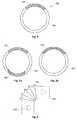
- Figure 5a and 5billustrate a shrink sleeve 500 according to a third and fourth embodiment of the present invention.
- the second polymer-based material 522 resistant to irradiationcovers an elongated area relative to the longitudinal axis of the shrink sleeve 500.
- Figure 6illustrates the cross-section of the shrink sleeve 300 depicted in figure 3 . As depicted, the outer surface of the shrink sleeve 300 is continuous.
- Figure 7a and 7billustrate two different cross sections of two different embodiments of the shrink sleeve 700 of the present invention.
- the shrink sleeve 700has two areas with a second polymer-based material 722 being more resistant to irradiation than the rest of the shrink sleeve.
- the second polymer-based material 722being more resistant to irradiation faces only the outer surface of the shrink sleeve 700.
- the inner wall of the shrink sleeve 700is constituted only by the first polymer-based material 720 being more susceptible to irradiation.
- FIG 8illustrates another embodiment of the shrink sleeve 800 of the present invention.
- the shrink sleeve 800consists of a first polymer-based material 820 susceptible to irradiation and a second polymer-based material 822 resistant to irradiation.
- the shrink sleeve 300, 400, 500, 700, 800could be manufactured by a two-component blow or injection molding process. These manufacturing processes could also be combined with an in-mould technique, such that the second polymer-based material 322, 422, 522, 722, 822 is inserted in the molding tool prior to injecting or leading the first polymer-based material 320, 420, 520, 720, 820 into the tool.
- the wall holes in the shrink sleevecan be varied both in terms of numbers and in terms of their position on the shrink sleeve.
Landscapes
- Engineering & Computer Science (AREA)
- General Engineering & Computer Science (AREA)
- Mechanical Engineering (AREA)
- Lining Or Joining Of Plastics Or The Like (AREA)
- Protection Of Pipes Against Damage, Friction, And Corrosion (AREA)
Description
- In the industry of district heating/cooling it is known to install and assemble pipelines by joining insulated pipes. In its most basic embodiment, the insulated pipe comprises an inner pipe, surrounded by a layer of insulation material, which again is covered by a casing. The inner pipe and the casing can be made of polymer-based materials and metals. Typically, the insulation pipes are though embodied with an inner pipe of metal, a closed-cell and/or solid thermal insulation layer and a polymer-based casing.
- The insulated pipes are manufactured in required lengths that enable transportation. The insulated pipes are manufactured such that the length of the inner pipe exceeds the length of the insulation layer and the casing. Thus at the end of the insulated pipe, the inner pipe protrudes relative to the insulation layer and the casing. At the installation site the insulated pipes are joined end-to-end, first by joining the inner pipes of the two insulated pipes lying end-to-end. Prior to welding the inner pipes, a shrink sleeve is drawn or pushed over the casing of one of the insulated pipes to be joined. After welding of the inner pipes, the shrink sleeve is moved so that it rests on the casing of the two insulated pipes. The ends of the shrink sleeve are subsequently shrunk impermeably onto the two casings of the two insulated pipes. This shrinking process is normally done by exposing the ends of the shrink sleeve to heat. Through a hole in the shrink sleeve, insulation material can be led into the cavity between the joined inner pipes and the sleeve. Through a second hole in the shrink sleeve a valve can be inserted. This valve will typically be embodied as an air valve. Hereby the joined inner pipes are insulated. The wall holes are hereafter to be impermeably closed. The impermeable closure of the wall holes is central to the functionality of the entire pipeline, as primarily the longitudinal movements of an installed pipeline can loosen or detach the plugs from the sleeve. Today it is known to weld or patch a plug onto an area in proximity to the holes.
- In the prior art the sleeve is a hollow shell with a tubular shape. The sleeve is normally made of a polymer-based material, which after manufacturing is exposed to irradiation such as an e-beam (electron beam). After such a treatment for example polyethylene is denoted PEX or PE-Xc. The sleeve is hereby cross-linked, meaning that the polymer fibers of the material will change direction and link to other layers (molecule chains). As an effect of this treatment, the polymer-based material obtains a high mechanical strength and a high temperature resistivity. Prior to irradiation, the sleeve is normally manufactured in such a way that the diameter of the ends is smaller than the diameter of the center section there between. The sleeve can, however, also have the same diameter along the entire length of the sleeve. After irradiation, the ends of the sleeve are heated and the diameter of these is extended, such that the diameter here will be equal to or greater than the diameter of the central section. The sleeve can after irradiation also be heated and extended such that the sleeve has the same diameter along its entire length. As described, the sleeve is fastened to the casing of the two insulated pipes by heating the ends, whereby the material here will try to reach its initial size. Hence, the material in the ends shrinks as a result of the heating thereof. The casing of the two pipes will prevent it from reaching the initial diameter, however, the sleeve will be firmly fastened to the casing of the two insulated pipes. This effect is a result of the cross linking of the material and the following extension of the diameter in the ends of the sleeve. Since the wall hole(s) of the sleeve will have to be impermeably closed or sealed off (plugged) after filling with or injecting the insulation material, the material around the wall hole cannot be fully cross-linked, as the cross-linked material has a high temperature resistivity. The process of closing the wall hole by welding a plug onto the sleeve does therefore simply not harmonize with the temperature resistivity of the sleeve material. Consequently, the welding process would be very difficult to perform, if not impossible. Hence, the cross linked material cannot melt sufficiently and thereby a complete integration with the sleeve material is not obtained, which is essential to a successful sealing of the wall hole using a welding process.
- It is known to solve this problem by mounting or clamping for example protective metal discs onto the wall material proximate to the wall hole. When the sleeve is exposed to irradiation, the wall material covered by the metal discs will only to a limited extent be exposed to irradiation and thereby not be completely cross linked. Hereby the material proximate to the wall hole becomes weldable in that the material has a lower temperature resistivity than the rest of the sleeve. The weldable properties of the material in proximity to the wall holes are, however, not sufficient to obtain the required welding quality and material integration. Further, the manufacturing process of mounting and dismounting the metal discs is a very time-consuming manual process, as for example one counterpart of the discs must be inserted through an end of the sleeve which at that time has a very small diameter. Consequently, this manual process contributes to very high manufacturing costs
- In an attempt to enhance weldability of the sleeve material in proximity to the holes,
US 2001/0041235 discloses a heat shrinkable member for forming a connection between tubular sections. The member comprises a tubular section which is cross-linked. In order to be able to close the wall holes of the member, an uncross-linked or less uncrossed-linked patch is bonded to the central section of the member. A wall hole for injection of insulation material is drilled through the patch and the cross-linked material. When the wall hole is to be closed, the plug is bonded to the patch. The patch can be attached to both inside and outside of the heat shrinkable member by fusion bonding or welding or by using of a conventional adhesive agent. The patch can be attached to the heat shrinkable member before or after the whole member is exposed to irradiation. Although the welding properties might be improved by this type of shrinkable member, the manufacturing cost associated with attaching the patches is essentially undesired. - The present invention relates to a shrink sleeve for joining the casing of two insulated pipes lying end-to-end, where the shrink sleeve has a tubular shape made of a first polymer-based material susceptible to irradiation. The tubular shape of the shrink sleeve consists of the first polymer-based material and a second polymer-based material, where the second polymer-based material is more resistant to irradiation than the first material. Further, the second polymer-based material can be weldable. In another embodiment the outer surface and/or the inner surface of the shrink sleeve are/is continuous. The shrink sleeve is advantageous in that it consists both of a material susceptible to irradiation and one resistant to irradiation in the same tubular shape. Hereby the shrink sleeve can be irradiated without changing its tubular shape or adding any parts, such as protective metal discs, prior to that treatment. In addition, the second polymer-based material of the shrink sleeve is weldable without jeopardizing the geometry of its tubular shape. The tubular shape of the shrink sleeve is essential to obtain a uniform isolation of the pipeline where shrink sleeves are placed. In addition, the continuous inner and/or outer surfaces of the shrink sleeve will enable a pipeline to extend longitudinally.
- In another embodiment of the shrink sleeve of the present invention, the second polymer-based material is placed in at least one delimited area of the shrink sleeve. The delimited area can be surrounded by the first polymer-based material, extend in the whole circumference of the shrink sleeve and/or extend in a part of the circumference of the shrink sleeve. The at least one delimited area of the second polymer-based material can also be approximately circular. Further, the second polymer-based material can be transparent or have a different color. Hereby a large degree of freedom is obtained in that wall holes can be placed where required. A transparent second polymer-based material enables inspection of for example the expansion process of liquid insulation material injected into the shrink sleeve.
- In the following, the invention will be described referring to the figures, where
figure 1 illustrates an insulated pipe of the prior art;figures 2a and 2b illustrate a shrink sleeve of the prior art;figure 3 illustrates a shrink sleeve according to a first embodiment of the present invention;figure 4 illustrates a shrink sleeve according to a second embodiment of the present invention;figure 5a and 5b illustrate a shrink sleeve according to a third and fourth embodiment of the present invention;figure 6 illustrates the cross-section of the shrink sleeve depicted infigure 3 ;figure 7a and 7b illustrate two different cross sections of two different embodiments of the shrink sleeve of the present invention, andfigure 8 illustrates yet another embodiment of the shrink sleeve of the present invention.Figure 1 illustrates aninsulated pipe 100 known in the art, comprising aninner pipe 101 surrounded by a layer ofinsulation material 103, which again is covered by acasing 102. Theinner pipe 101 and thecasing 102 can be made of polymer-based materials and metals. In the context of the present invention, theinsulated pipe 100 is embodied with aninner pipe 101 of metal or polymer, a closed-cell and/or solidthermal insulation layer 103 and a polymer-basedcasing 102.Figure 2a-b illustrate ashrink sleeve 200 of the prior art, wherefigure 2a illustrates theshrink sleeve 200, where the ends 205 of the shrink sleeve have not yet been expanded, andfigure 2b illustrates theshrink sleeve 200 after expansion of the ends 205. Theshrink sleeve 200 comprises two wall holes 210. Theshrink sleeve 200 is made of one material susceptible to irradiation. Prior to exposing theshrink sleeve 200 to irradiation, the wall material in proximity to the twowall holes 210 has been clamped with metal discs (not shown). The wall material covered by the metal discs will be exposed less to irradiation, than the rest of the shrink sleeve. Thereby the material in these less exposed areas is less cross-linked compared to the remaining part of theshrink sleeve 200. Although the material in proximity to the wall holes 210 has been less cross-linked. The material in the area which has been less crosslinked is more suitable for welding. Generally welding properties of the material are reduced as crosslinking is increased. After exposure to irradiation, theends 205 of theshrink sleeve 200 are expanded, seefigure 2b .Figure 3a illustrates ashrink sleeve 300 according to a first embodiment of the present invention. Theshrink sleeve 300 comprises a first polymer-basedmaterial 320 susceptible to irradiation and a second polymer-basedmaterial 322 more resistant to irradiation reducing the amount of cross linking significantly. After irradiation only the second polymer-basedmaterial 322 will be fully weldable. After irradiation, the diameter of the ends ofshrink sleeve 300 has been expanded, seefigure 3b . When joining the polymer-basedcasing 102 of the twoinsulated pipes 100, the ends of theshrink sleeve 300 will be fully shrinkable, as the material here has been fully cross-linked and subsequently expanded. In addition, the cavity between the joinedinner pipes 101 and theshrink sleeve 300 can be filled or injected with e.g. expanding insulation material through wall holes positioned in the second polymer-basedmaterial 322. Hereafter these wall holes can be plugged and closed impermeably by welding. The quality of that welding will with this embodiment not be jeopardized by the poor welding properties (high temperature resistivity) of the material in proximity to the wall holes as known in the prior art.Figure 4 illustrates ashrink sleeve 400 according to a second embodiment of the present invention. In this embodiment the second polymer-basedmaterial 422 resistant to irradiation covers the whole circumference of theshrink sleeve 400.Figure 5a and 5b illustrate ashrink sleeve 500 according to a third and fourth embodiment of the present invention. In this embodiment the second polymer-basedmaterial 522 resistant to irradiation covers an elongated area relative to the longitudinal axis of theshrink sleeve 500.Figure 6 illustrates the cross-section of theshrink sleeve 300 depicted infigure 3 . As depicted, the outer surface of theshrink sleeve 300 is continuous.Figure 7a and 7b illustrate two different cross sections of two different embodiments of the shrink sleeve 700 of the present invention. Infigure 7a the shrink sleeve 700 has two areas with a second polymer-basedmaterial 722 being more resistant to irradiation than the rest of the shrink sleeve. Infigure 7b the second polymer-basedmaterial 722 being more resistant to irradiation faces only the outer surface of the shrink sleeve 700. Thus, the inner wall of the shrink sleeve 700 is constituted only by the first polymer-basedmaterial 720 being more susceptible to irradiation.Figure 8 illustrates another embodiment of the shrink sleeve 800 of the present invention. The shrink sleeve 800 consists of a first polymer-basedmaterial 820 susceptible to irradiation and a second polymer-basedmaterial 822 resistant to irradiation.- The
shrink sleeve material material
Claims (10)
- A shrink sleeve for joining the casing of two insulated pipes lying end-to-end, where said shrink sleeve has a tubular shape comprising a first polymer-based material susceptible to irradiation,characterized in that said tubular shape of said shrink sleeve consists of said first polymer-based material and a second polymer-based material, where said second polymer-based material is significantly more resistant to said irradiation than said first polymer-based material.
- A shrink sleeve according to claim 1, where said second polymer-based material is weldable after irradiation.
- A shrink sleeve according to claims 1-2, where the outer surface of said shrink sleeve is continuous.
- A shrink sleeve according to claims 1-3, where the inner surface of said shrink sleeve is continuous.
- A shrink sleeve according to claims 1-4, where said second polymer-based material is placed in at least one delimited area of said shrink sleeve
- A shrink sleeve according to claims 1-5, where said second polymer-based material is surrounded by said first polymer-based material.
- A shrink sleeve according to claims 5-6, where said at least one delimited area of said second polymer-based material extends over the whole circumference of said shrink sleeve.
- A shrink sleeve according to claims 5-6, where said at least one delimited area of said second polymer-based material extends over a part of the circumference of said shrink sleeve.
- A shrink sleeve according to claims 5-6, where said at least one delimited area of said second polymer-based material is approximately circular.
- A shrink sleeve according to claims 1-9, where said second polymer-based material is transparent.
Priority Applications (1)
| Application Number | Priority Date | Filing Date | Title |
|---|---|---|---|
| PL11726327TPL2580511T3 (en) | 2010-06-09 | 2011-06-07 | Shrink sleeve for joining insulated pipes |
Applications Claiming Priority (2)
| Application Number | Priority Date | Filing Date | Title |
|---|---|---|---|
| DKPA201000497ADK201000497A (en) | 2010-06-09 | 2010-06-09 | Shrink sleeve for joining insulated pipes |
| PCT/DK2011/050199WO2011154005A1 (en) | 2010-06-09 | 2011-06-07 | Shrink sleeve for joining insulated pipes |
Publications (2)
| Publication Number | Publication Date |
|---|---|
| EP2580511A1 EP2580511A1 (en) | 2013-04-17 |
| EP2580511B1true EP2580511B1 (en) | 2014-04-16 |
Family
ID=44312397
Family Applications (1)
| Application Number | Title | Priority Date | Filing Date |
|---|---|---|---|
| EP11726327.7AActiveEP2580511B1 (en) | 2010-06-09 | 2011-06-07 | Shrink sleeve for joining insulated pipes |
Country Status (7)
| Country | Link |
|---|---|
| US (1) | US20130113210A1 (en) |
| EP (1) | EP2580511B1 (en) |
| CN (1) | CN103003612B (en) |
| DK (2) | DK201000497A (en) |
| MX (1) | MX2012014403A (en) |
| PL (1) | PL2580511T3 (en) |
| WO (1) | WO2011154005A1 (en) |
Families Citing this family (3)
| Publication number | Priority date | Publication date | Assignee | Title |
|---|---|---|---|---|
| FR3018333A1 (en) | 2014-03-10 | 2015-09-11 | Saint Gobain Performance Plast | |
| WO2017186388A1 (en)* | 2016-04-26 | 2017-11-02 | Logstor A/S | System, plug and method for sealing a hole in a sleeve positioned between insulated pipes |
| US11504918B2 (en) | 2020-02-14 | 2022-11-22 | Delta Faucet Company | Cross-linked pex forming after assembly |
Family Cites Families (23)
| Publication number | Priority date | Publication date | Assignee | Title |
|---|---|---|---|---|
| US2857915A (en)* | 1956-04-02 | 1958-10-28 | David S Sheridan | X-ray catheter |
| US3070132A (en)* | 1960-04-06 | 1962-12-25 | David S Sheridan | Non-sparking medico-surgical tubes |
| US3415287A (en)* | 1964-08-21 | 1968-12-10 | Raychem Corp | Protective covering and article |
| US3320355A (en)* | 1965-09-07 | 1967-05-16 | Aylwin R Booker | Heat shrinkable connector for electrical wire |
| US4027659A (en)* | 1975-11-21 | 1977-06-07 | Krandex Corporation | Radiographic opaque and conductive stripped medical tubes |
| US4657024A (en)* | 1980-02-04 | 1987-04-14 | Teleflex Incorporated | Medical-surgical catheter |
| FI76633C (en)* | 1981-10-27 | 1988-11-10 | Raychem Sa Nv | Tube protection sleeve and method for protecting a tube with this sleeve |
| ES8607108A1 (en)* | 1984-04-06 | 1986-06-01 | Raychem Sa Nv | Heat-recoverable article. |
| DK153723C (en)* | 1984-10-05 | 1988-12-27 | Danske Gasvaerkers Tjaere Komp | PLASTIC SHRINK MUFF TO JOIN TWO ROOMS |
| GB8507374D0 (en)* | 1985-03-21 | 1985-05-01 | Raychem Sa Nv | Coated recoverable articles |
| WO1989001311A1 (en)* | 1987-08-18 | 1989-02-23 | Medex, Inc. | Tubular pressure transducer |
| US5134000A (en)* | 1989-08-10 | 1992-07-28 | Shaw Industries Ltd. | Heat shrinkable protective sheets and methods for their manufacture |
| US6265065B1 (en)* | 1993-10-29 | 2001-07-24 | Mccallion James P. | Concrete reinforcement protection system |
| AR002142A1 (en)* | 1995-05-31 | 1998-01-07 | Raychem Sa Nv | A THERMAL-CONTRACTABLE TUBULAR ARTICLE, A SET OF PARTS INCLUDING IT, A METHOD TO MANUFACTURE IT AND A METHOD TO COVER A JOINT WITH IT. |
| GB2319316A (en)* | 1996-11-14 | 1998-05-20 | Shaw Ind Ltd | Heat shrinkable member for connecting tubular sections |
| GB2325501A (en)* | 1997-05-22 | 1998-11-25 | Uponor Ltd | Heat fusion fitting |
| CA2276708A1 (en) | 1999-06-30 | 2000-12-30 | Shaw Industries Ltd. | Casing with provision for closing an opening therein |
| US6337115B1 (en)* | 1999-07-30 | 2002-01-08 | Raytheon Company | Shape-recovering material suitable for application of non-distorting printed matter, and its use |
| US20040086674A1 (en)* | 2002-11-01 | 2004-05-06 | Holman Thomas J. | Laser sintering process and devices made therefrom |
| US7538161B2 (en)* | 2003-09-22 | 2009-05-26 | The Yokohama Rubber Co., Ltd. | Production and bonding method of elastomer composition |
| EP1741968A1 (en)* | 2005-07-08 | 2007-01-10 | Uponor Innovation Ab | Clamping ring |
| US7790288B2 (en)* | 2005-08-11 | 2010-09-07 | 3M Innovative Properties Company | Interpenetrating polymer network as coating for metal substrate and method therefor |
| CN201121791Y (en)* | 2007-11-05 | 2008-09-24 | 深圳市宏商热缩材料有限公司 | Coating type thermal shrinkage stress control tube |
- 2010
- 2010-06-09DKDKPA201000497Apatent/DK201000497A/ennot_activeApplication Discontinuation
- 2011
- 2011-06-07USUS13/702,301patent/US20130113210A1/ennot_activeAbandoned
- 2011-06-07CNCN201180028290.5Apatent/CN103003612B/enactiveActive
- 2011-06-07EPEP11726327.7Apatent/EP2580511B1/enactiveActive
- 2011-06-07DKDK11726327.7Tpatent/DK2580511T3/enactive
- 2011-06-07WOPCT/DK2011/050199patent/WO2011154005A1/enactiveApplication Filing
- 2011-06-07MXMX2012014403Apatent/MX2012014403A/enunknown
- 2011-06-07PLPL11726327Tpatent/PL2580511T3/enunknown
Also Published As
| Publication number | Publication date |
|---|---|
| DK2580511T3 (en) | 2014-05-19 |
| DK201000497A (en) | 2011-12-10 |
| CN103003612B (en) | 2014-12-10 |
| PL2580511T3 (en) | 2014-09-30 |
| US20130113210A1 (en) | 2013-05-09 |
| WO2011154005A1 (en) | 2011-12-15 |
| CN103003612A (en) | 2013-03-27 |
| MX2012014403A (en) | 2013-03-12 |
| EP2580511A1 (en) | 2013-04-17 |
Similar Documents
| Publication | Publication Date | Title |
|---|---|---|
| US11168827B2 (en) | Method of and system for coating a field joint of a pipe | |
| PL185783B1 (en) | Integrated housing member for jointing together adjacent pipe sections and method of making such integrated housing member | |
| WO2010121339A1 (en) | Method for the highly-thick thermal coating of joints by using electrofusion in pipes used for conducting fluids, made of steel tubes externally coated with polyolefins | |
| KR102404567B1 (en) | Heat shrink casing for double heat insulation tube, method for manufacturing heat shrink casing for double heat insulation tube and method for constructing heat shrink casing for double heat insulation tube | |
| EP2580511B1 (en) | Shrink sleeve for joining insulated pipes | |
| KR101635426B1 (en) | Casing for connecting double insulation pipe, method for manufacturing the casing, and method for connecting double insulation pipe using the casing | |
| CA2641033A1 (en) | Coupling construction for high-pressure pipe | |
| WO2018167736A2 (en) | Method for lining by electrofusion joints of on-shore pipelines used for conveying fluids, formed by pipes externally lined with polyurethane foam and covered or enveloped with polyethylene sheets, and joint produced by this method | |
| RU2267687C1 (en) | Thermally shrinkable coupling | |
| KR101655315B1 (en) | Polyurethane forming Cap of heat shrinkable casing for double insulation pipe | |
| WO2002070235A2 (en) | Method of joining prefabricated thermal insulated pipes | |
| KR100625895B1 (en) | Heat shrinkable tube | |
| EP1108179B1 (en) | Casing with provision for closing an opening therein | |
| KR200387864Y1 (en) | Device for connecting underground pipes | |
| JP2011163524A (en) | Pipe connecting structure and pipe connecting method | |
| RU43940U1 (en) | THERMAL SHrinkable Coupling | |
| AU2017270665B2 (en) | Method for connecting two individual fluid transport pipe elements using rigid shells | |
| RU2611219C1 (en) | Method for sealing joints of pre-insulated pipes | |
| FI112338B (en) | Process for making a well and a well | |
| RU2611218C1 (en) | Method for sealing pre-insulated pipes joint | |
| PL205918B1 (en) | Thermo shrink sleeve and method for the manufacture of thermo shrink sleeves | |
| RU2386071C2 (en) | Pipeline for fluid medium and method of its manufacturing | |
| KR20040042409A (en) | Connecting pipe embeded with heating coil for plastic pipes |
Legal Events
| Date | Code | Title | Description |
|---|---|---|---|
| PUAI | Public reference made under article 153(3) epc to a published international application that has entered the european phase | Free format text:ORIGINAL CODE: 0009012 | |
| 17P | Request for examination filed | Effective date:20121128 | |
| AK | Designated contracting states | Kind code of ref document:A1 Designated state(s):AL AT BE BG CH CY CZ DE DK EE ES FI FR GB GR HR HU IE IS IT LI LT LU LV MC MK MT NL NO PL PT RO RS SE SI SK SM TR | |
| DAX | Request for extension of the european patent (deleted) | ||
| GRAP | Despatch of communication of intention to grant a patent | Free format text:ORIGINAL CODE: EPIDOSNIGR1 | |
| INTG | Intention to grant announced | Effective date:20131122 | |
| GRAS | Grant fee paid | Free format text:ORIGINAL CODE: EPIDOSNIGR3 | |
| GRAA | (expected) grant | Free format text:ORIGINAL CODE: 0009210 | |
| AK | Designated contracting states | Kind code of ref document:B1 Designated state(s):AL AT BE BG CH CY CZ DE DK EE ES FI FR GB GR HR HU IE IS IT LI LT LU LV MC MK MT NL NO PL PT RO RS SE SI SK SM TR | |
| REG | Reference to a national code | Ref country code:GB Ref legal event code:FG4D | |
| REG | Reference to a national code | Ref country code:CH Ref legal event code:EP | |
| REG | Reference to a national code | Ref country code:AT Ref legal event code:REF Ref document number:662787 Country of ref document:AT Kind code of ref document:T Effective date:20140515 | |
| REG | Reference to a national code | Ref country code:DK Ref legal event code:T3 Effective date:20140515 | |
| REG | Reference to a national code | Ref country code:IE Ref legal event code:FG4D | |
| REG | Reference to a national code | Ref country code:DE Ref legal event code:R096 Ref document number:602011006244 Country of ref document:DE Effective date:20140528 | |
| REG | Reference to a national code | Ref country code:RO Ref legal event code:EPE | |
| REG | Reference to a national code | Ref country code:SK Ref legal event code:T3 Ref document number:E 16629 Country of ref document:SK | |
| REG | Reference to a national code | Ref country code:NL Ref legal event code:VDEP Effective date:20140416 | |
| REG | Reference to a national code | Ref country code:LT Ref legal event code:MG4D | |
| REG | Reference to a national code | Ref country code:PL Ref legal event code:T3 | |
| PG25 | Lapsed in a contracting state [announced via postgrant information from national office to epo] | Ref country code:CY Free format text:LAPSE BECAUSE OF FAILURE TO SUBMIT A TRANSLATION OF THE DESCRIPTION OR TO PAY THE FEE WITHIN THE PRESCRIBED TIME-LIMIT Effective date:20140416 Ref country code:IS Free format text:LAPSE BECAUSE OF FAILURE TO SUBMIT A TRANSLATION OF THE DESCRIPTION OR TO PAY THE FEE WITHIN THE PRESCRIBED TIME-LIMIT Effective date:20140816 Ref country code:NO Free format text:LAPSE BECAUSE OF FAILURE TO SUBMIT A TRANSLATION OF THE DESCRIPTION OR TO PAY THE FEE WITHIN THE PRESCRIBED TIME-LIMIT Effective date:20140716 Ref country code:LT Free format text:LAPSE BECAUSE OF FAILURE TO SUBMIT A TRANSLATION OF THE DESCRIPTION OR TO PAY THE FEE WITHIN THE PRESCRIBED TIME-LIMIT Effective date:20140416 Ref country code:GR Free format text:LAPSE BECAUSE OF FAILURE TO SUBMIT A TRANSLATION OF THE DESCRIPTION OR TO PAY THE FEE WITHIN THE PRESCRIBED TIME-LIMIT Effective date:20140717 Ref country code:FI Free format text:LAPSE BECAUSE OF FAILURE TO SUBMIT A TRANSLATION OF THE DESCRIPTION OR TO PAY THE FEE WITHIN THE PRESCRIBED TIME-LIMIT Effective date:20140416 Ref country code:NL Free format text:LAPSE BECAUSE OF FAILURE TO SUBMIT A TRANSLATION OF THE DESCRIPTION OR TO PAY THE FEE WITHIN THE PRESCRIBED TIME-LIMIT Effective date:20140416 Ref country code:BG Free format text:LAPSE BECAUSE OF FAILURE TO SUBMIT A TRANSLATION OF THE DESCRIPTION OR TO PAY THE FEE WITHIN THE PRESCRIBED TIME-LIMIT Effective date:20140716 | |
| PG25 | Lapsed in a contracting state [announced via postgrant information from national office to epo] | Ref country code:RS Free format text:LAPSE BECAUSE OF FAILURE TO SUBMIT A TRANSLATION OF THE DESCRIPTION OR TO PAY THE FEE WITHIN THE PRESCRIBED TIME-LIMIT Effective date:20140416 Ref country code:HR Free format text:LAPSE BECAUSE OF FAILURE TO SUBMIT A TRANSLATION OF THE DESCRIPTION OR TO PAY THE FEE WITHIN THE PRESCRIBED TIME-LIMIT Effective date:20140416 Ref country code:SE Free format text:LAPSE BECAUSE OF FAILURE TO SUBMIT A TRANSLATION OF THE DESCRIPTION OR TO PAY THE FEE WITHIN THE PRESCRIBED TIME-LIMIT Effective date:20140416 Ref country code:ES Free format text:LAPSE BECAUSE OF FAILURE TO SUBMIT A TRANSLATION OF THE DESCRIPTION OR TO PAY THE FEE WITHIN THE PRESCRIBED TIME-LIMIT Effective date:20140416 Ref country code:LV Free format text:LAPSE BECAUSE OF FAILURE TO SUBMIT A TRANSLATION OF THE DESCRIPTION OR TO PAY THE FEE WITHIN THE PRESCRIBED TIME-LIMIT Effective date:20140416 | |
| PG25 | Lapsed in a contracting state [announced via postgrant information from national office to epo] | Ref country code:PT Free format text:LAPSE BECAUSE OF FAILURE TO SUBMIT A TRANSLATION OF THE DESCRIPTION OR TO PAY THE FEE WITHIN THE PRESCRIBED TIME-LIMIT Effective date:20140818 | |
| REG | Reference to a national code | Ref country code:DE Ref legal event code:R097 Ref document number:602011006244 Country of ref document:DE | |
| PG25 | Lapsed in a contracting state [announced via postgrant information from national office to epo] | Ref country code:MC Free format text:LAPSE BECAUSE OF FAILURE TO SUBMIT A TRANSLATION OF THE DESCRIPTION OR TO PAY THE FEE WITHIN THE PRESCRIBED TIME-LIMIT Effective date:20140416 Ref country code:LU Free format text:LAPSE BECAUSE OF FAILURE TO SUBMIT A TRANSLATION OF THE DESCRIPTION OR TO PAY THE FEE WITHIN THE PRESCRIBED TIME-LIMIT Effective date:20140607 Ref country code:EE Free format text:LAPSE BECAUSE OF FAILURE TO SUBMIT A TRANSLATION OF THE DESCRIPTION OR TO PAY THE FEE WITHIN THE PRESCRIBED TIME-LIMIT Effective date:20140416 Ref country code:CZ Free format text:LAPSE BECAUSE OF FAILURE TO SUBMIT A TRANSLATION OF THE DESCRIPTION OR TO PAY THE FEE WITHIN THE PRESCRIBED TIME-LIMIT Effective date:20140416 Ref country code:BE Free format text:LAPSE BECAUSE OF FAILURE TO SUBMIT A TRANSLATION OF THE DESCRIPTION OR TO PAY THE FEE WITHIN THE PRESCRIBED TIME-LIMIT Effective date:20140416 | |
| REG | Reference to a national code | Ref country code:CH Ref legal event code:PL | |
| PLBE | No opposition filed within time limit | Free format text:ORIGINAL CODE: 0009261 | |
| STAA | Information on the status of an ep patent application or granted ep patent | Free format text:STATUS: NO OPPOSITION FILED WITHIN TIME LIMIT | |
| 26N | No opposition filed | Effective date:20150119 | |
| REG | Reference to a national code | Ref country code:FR Ref legal event code:ST Effective date:20150227 | |
| PG25 | Lapsed in a contracting state [announced via postgrant information from national office to epo] | Ref country code:IT Free format text:LAPSE BECAUSE OF FAILURE TO SUBMIT A TRANSLATION OF THE DESCRIPTION OR TO PAY THE FEE WITHIN THE PRESCRIBED TIME-LIMIT Effective date:20140416 | |
| PG25 | Lapsed in a contracting state [announced via postgrant information from national office to epo] | Ref country code:CH Free format text:LAPSE BECAUSE OF NON-PAYMENT OF DUE FEES Effective date:20140630 Ref country code:LI Free format text:LAPSE BECAUSE OF NON-PAYMENT OF DUE FEES Effective date:20140630 | |
| REG | Reference to a national code | Ref country code:DE Ref legal event code:R097 Ref document number:602011006244 Country of ref document:DE Effective date:20150119 | |
| PG25 | Lapsed in a contracting state [announced via postgrant information from national office to epo] | Ref country code:FR Free format text:LAPSE BECAUSE OF NON-PAYMENT OF DUE FEES Effective date:20140630 | |
| PG25 | Lapsed in a contracting state [announced via postgrant information from national office to epo] | Ref country code:SI Free format text:LAPSE BECAUSE OF FAILURE TO SUBMIT A TRANSLATION OF THE DESCRIPTION OR TO PAY THE FEE WITHIN THE PRESCRIBED TIME-LIMIT Effective date:20140416 | |
| GBPC | Gb: european patent ceased through non-payment of renewal fee | Effective date:20150607 | |
| PG25 | Lapsed in a contracting state [announced via postgrant information from national office to epo] | Ref country code:MT Free format text:LAPSE BECAUSE OF FAILURE TO SUBMIT A TRANSLATION OF THE DESCRIPTION OR TO PAY THE FEE WITHIN THE PRESCRIBED TIME-LIMIT Effective date:20140416 | |
| REG | Reference to a national code | Ref country code:IE Ref legal event code:MM4A | |
| PG25 | Lapsed in a contracting state [announced via postgrant information from national office to epo] | Ref country code:SM Free format text:LAPSE BECAUSE OF FAILURE TO SUBMIT A TRANSLATION OF THE DESCRIPTION OR TO PAY THE FEE WITHIN THE PRESCRIBED TIME-LIMIT Effective date:20140416 Ref country code:GB Free format text:LAPSE BECAUSE OF NON-PAYMENT OF DUE FEES Effective date:20150607 | |
| PG25 | Lapsed in a contracting state [announced via postgrant information from national office to epo] | Ref country code:IE Free format text:LAPSE BECAUSE OF NON-PAYMENT OF DUE FEES Effective date:20140607 Ref country code:HU Free format text:LAPSE BECAUSE OF FAILURE TO SUBMIT A TRANSLATION OF THE DESCRIPTION OR TO PAY THE FEE WITHIN THE PRESCRIBED TIME-LIMIT; INVALID AB INITIO Effective date:20110607 Ref country code:TR Free format text:LAPSE BECAUSE OF FAILURE TO SUBMIT A TRANSLATION OF THE DESCRIPTION OR TO PAY THE FEE WITHIN THE PRESCRIBED TIME-LIMIT Effective date:20140416 | |
| PG25 | Lapsed in a contracting state [announced via postgrant information from national office to epo] | Ref country code:MK Free format text:LAPSE BECAUSE OF FAILURE TO SUBMIT A TRANSLATION OF THE DESCRIPTION OR TO PAY THE FEE WITHIN THE PRESCRIBED TIME-LIMIT Effective date:20140416 | |
| PG25 | Lapsed in a contracting state [announced via postgrant information from national office to epo] | Ref country code:AL Free format text:LAPSE BECAUSE OF FAILURE TO SUBMIT A TRANSLATION OF THE DESCRIPTION OR TO PAY THE FEE WITHIN THE PRESCRIBED TIME-LIMIT Effective date:20140416 | |
| P01 | Opt-out of the competence of the unified patent court (upc) registered | Effective date:20230530 | |
| PGFP | Annual fee paid to national office [announced via postgrant information from national office to epo] | Ref country code:PL Payment date:20250527 Year of fee payment:15 Ref country code:DE Payment date:20250305 Year of fee payment:15 | |
| PGFP | Annual fee paid to national office [announced via postgrant information from national office to epo] | Ref country code:DK Payment date:20250404 Year of fee payment:15 | |
| PGFP | Annual fee paid to national office [announced via postgrant information from national office to epo] | Ref country code:AT Payment date:20250617 Year of fee payment:15 Ref country code:RO Payment date:20250527 Year of fee payment:15 | |
| PGFP | Annual fee paid to national office [announced via postgrant information from national office to epo] | Ref country code:SK Payment date:20250520 Year of fee payment:15 |