EP2579815B1 - Prosthetic for partial replacement of a long bone - Google Patents
Prosthetic for partial replacement of a long boneDownload PDFInfo
- Publication number
- EP2579815B1 EP2579815B1EP11724563.9AEP11724563AEP2579815B1EP 2579815 B1EP2579815 B1EP 2579815B1EP 11724563 AEP11724563 AEP 11724563AEP 2579815 B1EP2579815 B1EP 2579815B1
- Authority
- EP
- European Patent Office
- Prior art keywords
- prosthesis according
- length
- prosthesis
- shaft
- outer rod
- Prior art date
- Legal status (The legal status is an assumption and is not a legal conclusion. Google has not performed a legal analysis and makes no representation as to the accuracy of the status listed.)
- Active
Links
Images


Classifications
- A—HUMAN NECESSITIES
- A61—MEDICAL OR VETERINARY SCIENCE; HYGIENE
- A61F—FILTERS IMPLANTABLE INTO BLOOD VESSELS; PROSTHESES; DEVICES PROVIDING PATENCY TO, OR PREVENTING COLLAPSING OF, TUBULAR STRUCTURES OF THE BODY, e.g. STENTS; ORTHOPAEDIC, NURSING OR CONTRACEPTIVE DEVICES; FOMENTATION; TREATMENT OR PROTECTION OF EYES OR EARS; BANDAGES, DRESSINGS OR ABSORBENT PADS; FIRST-AID KITS
- A61F2/00—Filters implantable into blood vessels; Prostheses, i.e. artificial substitutes or replacements for parts of the body; Appliances for connecting them with the body; Devices providing patency to, or preventing collapsing of, tubular structures of the body, e.g. stents
- A61F2/02—Prostheses implantable into the body
- A61F2/30—Joints
- A61F2/38—Joints for elbows or knees
- A—HUMAN NECESSITIES
- A61—MEDICAL OR VETERINARY SCIENCE; HYGIENE
- A61F—FILTERS IMPLANTABLE INTO BLOOD VESSELS; PROSTHESES; DEVICES PROVIDING PATENCY TO, OR PREVENTING COLLAPSING OF, TUBULAR STRUCTURES OF THE BODY, e.g. STENTS; ORTHOPAEDIC, NURSING OR CONTRACEPTIVE DEVICES; FOMENTATION; TREATMENT OR PROTECTION OF EYES OR EARS; BANDAGES, DRESSINGS OR ABSORBENT PADS; FIRST-AID KITS
- A61F2/00—Filters implantable into blood vessels; Prostheses, i.e. artificial substitutes or replacements for parts of the body; Appliances for connecting them with the body; Devices providing patency to, or preventing collapsing of, tubular structures of the body, e.g. stents
- A61F2/02—Prostheses implantable into the body
- A61F2/30—Joints
- A—HUMAN NECESSITIES
- A61—MEDICAL OR VETERINARY SCIENCE; HYGIENE
- A61F—FILTERS IMPLANTABLE INTO BLOOD VESSELS; PROSTHESES; DEVICES PROVIDING PATENCY TO, OR PREVENTING COLLAPSING OF, TUBULAR STRUCTURES OF THE BODY, e.g. STENTS; ORTHOPAEDIC, NURSING OR CONTRACEPTIVE DEVICES; FOMENTATION; TREATMENT OR PROTECTION OF EYES OR EARS; BANDAGES, DRESSINGS OR ABSORBENT PADS; FIRST-AID KITS
- A61F2/00—Filters implantable into blood vessels; Prostheses, i.e. artificial substitutes or replacements for parts of the body; Appliances for connecting them with the body; Devices providing patency to, or preventing collapsing of, tubular structures of the body, e.g. stents
- A61F2/02—Prostheses implantable into the body
- A61F2/28—Bones
- A—HUMAN NECESSITIES
- A61—MEDICAL OR VETERINARY SCIENCE; HYGIENE
- A61F—FILTERS IMPLANTABLE INTO BLOOD VESSELS; PROSTHESES; DEVICES PROVIDING PATENCY TO, OR PREVENTING COLLAPSING OF, TUBULAR STRUCTURES OF THE BODY, e.g. STENTS; ORTHOPAEDIC, NURSING OR CONTRACEPTIVE DEVICES; FOMENTATION; TREATMENT OR PROTECTION OF EYES OR EARS; BANDAGES, DRESSINGS OR ABSORBENT PADS; FIRST-AID KITS
- A61F2/00—Filters implantable into blood vessels; Prostheses, i.e. artificial substitutes or replacements for parts of the body; Appliances for connecting them with the body; Devices providing patency to, or preventing collapsing of, tubular structures of the body, e.g. stents
- A61F2/02—Prostheses implantable into the body
- A61F2/30—Joints
- A61F2/32—Joints for the hip
- A61F2/36—Femoral heads ; Femoral endoprostheses
- A61F2/3607—Femoral heads ; Femoral endoprostheses including proximal or total replacement of the femur
- A—HUMAN NECESSITIES
- A61—MEDICAL OR VETERINARY SCIENCE; HYGIENE
- A61F—FILTERS IMPLANTABLE INTO BLOOD VESSELS; PROSTHESES; DEVICES PROVIDING PATENCY TO, OR PREVENTING COLLAPSING OF, TUBULAR STRUCTURES OF THE BODY, e.g. STENTS; ORTHOPAEDIC, NURSING OR CONTRACEPTIVE DEVICES; FOMENTATION; TREATMENT OR PROTECTION OF EYES OR EARS; BANDAGES, DRESSINGS OR ABSORBENT PADS; FIRST-AID KITS
- A61F2/00—Filters implantable into blood vessels; Prostheses, i.e. artificial substitutes or replacements for parts of the body; Appliances for connecting them with the body; Devices providing patency to, or preventing collapsing of, tubular structures of the body, e.g. stents
- A61F2/02—Prostheses implantable into the body
- A61F2/30—Joints
- A61F2/38—Joints for elbows or knees
- A61F2/3859—Femoral components
- A—HUMAN NECESSITIES
- A61—MEDICAL OR VETERINARY SCIENCE; HYGIENE
- A61F—FILTERS IMPLANTABLE INTO BLOOD VESSELS; PROSTHESES; DEVICES PROVIDING PATENCY TO, OR PREVENTING COLLAPSING OF, TUBULAR STRUCTURES OF THE BODY, e.g. STENTS; ORTHOPAEDIC, NURSING OR CONTRACEPTIVE DEVICES; FOMENTATION; TREATMENT OR PROTECTION OF EYES OR EARS; BANDAGES, DRESSINGS OR ABSORBENT PADS; FIRST-AID KITS
- A61F2/00—Filters implantable into blood vessels; Prostheses, i.e. artificial substitutes or replacements for parts of the body; Appliances for connecting them with the body; Devices providing patency to, or preventing collapsing of, tubular structures of the body, e.g. stents
- A61F2/02—Prostheses implantable into the body
- A61F2/30—Joints
- A61F2002/30001—Additional features of subject-matter classified in A61F2/28, A61F2/30 and subgroups thereof
- A61F2002/30316—The prosthesis having different structural features at different locations within the same prosthesis; Connections between prosthetic parts; Special structural features of bone or joint prostheses not otherwise provided for
- A61F2002/30329—Connections or couplings between prosthetic parts, e.g. between modular parts; Connecting elements
- A61F2002/30331—Connections or couplings between prosthetic parts, e.g. between modular parts; Connecting elements made by longitudinally pushing a protrusion into a complementarily-shaped recess, e.g. held by friction fit
- A61F2002/30332—Conically- or frustoconically-shaped protrusion and recess
- A—HUMAN NECESSITIES
- A61—MEDICAL OR VETERINARY SCIENCE; HYGIENE
- A61F—FILTERS IMPLANTABLE INTO BLOOD VESSELS; PROSTHESES; DEVICES PROVIDING PATENCY TO, OR PREVENTING COLLAPSING OF, TUBULAR STRUCTURES OF THE BODY, e.g. STENTS; ORTHOPAEDIC, NURSING OR CONTRACEPTIVE DEVICES; FOMENTATION; TREATMENT OR PROTECTION OF EYES OR EARS; BANDAGES, DRESSINGS OR ABSORBENT PADS; FIRST-AID KITS
- A61F2/00—Filters implantable into blood vessels; Prostheses, i.e. artificial substitutes or replacements for parts of the body; Appliances for connecting them with the body; Devices providing patency to, or preventing collapsing of, tubular structures of the body, e.g. stents
- A61F2/02—Prostheses implantable into the body
- A61F2/30—Joints
- A61F2002/30001—Additional features of subject-matter classified in A61F2/28, A61F2/30 and subgroups thereof
- A61F2002/30316—The prosthesis having different structural features at different locations within the same prosthesis; Connections between prosthetic parts; Special structural features of bone or joint prostheses not otherwise provided for
- A61F2002/30329—Connections or couplings between prosthetic parts, e.g. between modular parts; Connecting elements
- A61F2002/30476—Connections or couplings between prosthetic parts, e.g. between modular parts; Connecting elements locked by an additional locking mechanism
- A61F2002/30495—Connections or couplings between prosthetic parts, e.g. between modular parts; Connecting elements locked by an additional locking mechanism using a locking ring
- A—HUMAN NECESSITIES
- A61—MEDICAL OR VETERINARY SCIENCE; HYGIENE
- A61F—FILTERS IMPLANTABLE INTO BLOOD VESSELS; PROSTHESES; DEVICES PROVIDING PATENCY TO, OR PREVENTING COLLAPSING OF, TUBULAR STRUCTURES OF THE BODY, e.g. STENTS; ORTHOPAEDIC, NURSING OR CONTRACEPTIVE DEVICES; FOMENTATION; TREATMENT OR PROTECTION OF EYES OR EARS; BANDAGES, DRESSINGS OR ABSORBENT PADS; FIRST-AID KITS
- A61F2/00—Filters implantable into blood vessels; Prostheses, i.e. artificial substitutes or replacements for parts of the body; Appliances for connecting them with the body; Devices providing patency to, or preventing collapsing of, tubular structures of the body, e.g. stents
- A61F2/02—Prostheses implantable into the body
- A61F2/30—Joints
- A61F2002/30001—Additional features of subject-matter classified in A61F2/28, A61F2/30 and subgroups thereof
- A61F2002/30316—The prosthesis having different structural features at different locations within the same prosthesis; Connections between prosthetic parts; Special structural features of bone or joint prostheses not otherwise provided for
- A61F2002/30329—Connections or couplings between prosthetic parts, e.g. between modular parts; Connecting elements
- A61F2002/30476—Connections or couplings between prosthetic parts, e.g. between modular parts; Connecting elements locked by an additional locking mechanism
- A61F2002/30507—Connections or couplings between prosthetic parts, e.g. between modular parts; Connecting elements locked by an additional locking mechanism using a threaded locking member, e.g. a locking screw or a set screw
- A—HUMAN NECESSITIES
- A61—MEDICAL OR VETERINARY SCIENCE; HYGIENE
- A61F—FILTERS IMPLANTABLE INTO BLOOD VESSELS; PROSTHESES; DEVICES PROVIDING PATENCY TO, OR PREVENTING COLLAPSING OF, TUBULAR STRUCTURES OF THE BODY, e.g. STENTS; ORTHOPAEDIC, NURSING OR CONTRACEPTIVE DEVICES; FOMENTATION; TREATMENT OR PROTECTION OF EYES OR EARS; BANDAGES, DRESSINGS OR ABSORBENT PADS; FIRST-AID KITS
- A61F2/00—Filters implantable into blood vessels; Prostheses, i.e. artificial substitutes or replacements for parts of the body; Appliances for connecting them with the body; Devices providing patency to, or preventing collapsing of, tubular structures of the body, e.g. stents
- A61F2/02—Prostheses implantable into the body
- A61F2/30—Joints
- A61F2002/30001—Additional features of subject-matter classified in A61F2/28, A61F2/30 and subgroups thereof
- A61F2002/30316—The prosthesis having different structural features at different locations within the same prosthesis; Connections between prosthetic parts; Special structural features of bone or joint prostheses not otherwise provided for
- A61F2002/30535—Special structural features of bone or joint prostheses not otherwise provided for
- A61F2002/30537—Special structural features of bone or joint prostheses not otherwise provided for adjustable
- A61F2002/3055—Special structural features of bone or joint prostheses not otherwise provided for adjustable for adjusting length
- A—HUMAN NECESSITIES
- A61—MEDICAL OR VETERINARY SCIENCE; HYGIENE
- A61F—FILTERS IMPLANTABLE INTO BLOOD VESSELS; PROSTHESES; DEVICES PROVIDING PATENCY TO, OR PREVENTING COLLAPSING OF, TUBULAR STRUCTURES OF THE BODY, e.g. STENTS; ORTHOPAEDIC, NURSING OR CONTRACEPTIVE DEVICES; FOMENTATION; TREATMENT OR PROTECTION OF EYES OR EARS; BANDAGES, DRESSINGS OR ABSORBENT PADS; FIRST-AID KITS
- A61F2/00—Filters implantable into blood vessels; Prostheses, i.e. artificial substitutes or replacements for parts of the body; Appliances for connecting them with the body; Devices providing patency to, or preventing collapsing of, tubular structures of the body, e.g. stents
- A61F2/02—Prostheses implantable into the body
- A61F2/30—Joints
- A61F2002/30001—Additional features of subject-matter classified in A61F2/28, A61F2/30 and subgroups thereof
- A61F2002/30316—The prosthesis having different structural features at different locations within the same prosthesis; Connections between prosthetic parts; Special structural features of bone or joint prostheses not otherwise provided for
- A61F2002/30535—Special structural features of bone or joint prostheses not otherwise provided for
- A61F2002/30601—Special structural features of bone or joint prostheses not otherwise provided for telescopic
- A—HUMAN NECESSITIES
- A61—MEDICAL OR VETERINARY SCIENCE; HYGIENE
- A61F—FILTERS IMPLANTABLE INTO BLOOD VESSELS; PROSTHESES; DEVICES PROVIDING PATENCY TO, OR PREVENTING COLLAPSING OF, TUBULAR STRUCTURES OF THE BODY, e.g. STENTS; ORTHOPAEDIC, NURSING OR CONTRACEPTIVE DEVICES; FOMENTATION; TREATMENT OR PROTECTION OF EYES OR EARS; BANDAGES, DRESSINGS OR ABSORBENT PADS; FIRST-AID KITS
- A61F2/00—Filters implantable into blood vessels; Prostheses, i.e. artificial substitutes or replacements for parts of the body; Appliances for connecting them with the body; Devices providing patency to, or preventing collapsing of, tubular structures of the body, e.g. stents
- A61F2/02—Prostheses implantable into the body
- A61F2/30—Joints
- A61F2002/30001—Additional features of subject-matter classified in A61F2/28, A61F2/30 and subgroups thereof
- A61F2002/30316—The prosthesis having different structural features at different locations within the same prosthesis; Connections between prosthetic parts; Special structural features of bone or joint prostheses not otherwise provided for
- A61F2002/30535—Special structural features of bone or joint prostheses not otherwise provided for
- A61F2002/30604—Special structural features of bone or joint prostheses not otherwise provided for modular
- A—HUMAN NECESSITIES
- A61—MEDICAL OR VETERINARY SCIENCE; HYGIENE
- A61F—FILTERS IMPLANTABLE INTO BLOOD VESSELS; PROSTHESES; DEVICES PROVIDING PATENCY TO, OR PREVENTING COLLAPSING OF, TUBULAR STRUCTURES OF THE BODY, e.g. STENTS; ORTHOPAEDIC, NURSING OR CONTRACEPTIVE DEVICES; FOMENTATION; TREATMENT OR PROTECTION OF EYES OR EARS; BANDAGES, DRESSINGS OR ABSORBENT PADS; FIRST-AID KITS
- A61F2/00—Filters implantable into blood vessels; Prostheses, i.e. artificial substitutes or replacements for parts of the body; Appliances for connecting them with the body; Devices providing patency to, or preventing collapsing of, tubular structures of the body, e.g. stents
- A61F2/02—Prostheses implantable into the body
- A61F2/30—Joints
- A61F2002/30001—Additional features of subject-matter classified in A61F2/28, A61F2/30 and subgroups thereof
- A61F2002/30316—The prosthesis having different structural features at different locations within the same prosthesis; Connections between prosthetic parts; Special structural features of bone or joint prostheses not otherwise provided for
- A61F2002/30535—Special structural features of bone or joint prostheses not otherwise provided for
- A61F2002/30617—Visible markings for adjusting, locating or measuring
Definitions
- the inventionrelates to a prosthesis for at least partial replacement of a long bone and an adjacent joint. It comprises an elongated shaft having first and second ends, and a hinge means disposed at the second end of the shaft. There is provided a length adjustment direction which telescopically shifts the shaft along its axis.
- the inventionfurther extends to a prosthesis module system with replaceable stems.
- the shafthas an outer and an inner rod, on which acts the length adjustment. This can be acted upon directly by means of a suitable tool on the length adjustment, which shifts according to the outer rod telescopically relative to the inner rod.
- the outer rodadvantageously has a pressure flange which has two opposing collar surfaces, one of which forms a thrust bearing for the conical connection and the other a stop for the length adjustment.
- the inventionfurther extends to a prosthesis system having a plurality of coupled differently long, in particular rigid, shaft elements which can be coupled via the plug connectors, wherein preferably at least one of the particularly rigid shaft elements has the same length as the length adjustment device in its basic position.
- a prosthesis systemhaving a plurality of coupled differently long, in particular rigid, shaft elements which can be coupled via the plug connectors, wherein preferably at least one of the particularly rigid shaft elements has the same length as the length adjustment device in its basic position.
- the adjusting nuthas a polished peripheral surface.
- a negative effect of the surrounding tissueis avoided on the adjusting nut, so that it hardly comes to adhesions.
- the adjusting nutthus remains adjustable even after several years of implantation, and is not blocked by growing tissue (connective tissue).
- the polished peripheral surfacecan also be achieved by a different surface design, which leads to a Reduction of buildup leads. Anodization of the surface is possible, in particular in the case of endoprostheses made of titanium.
- depressionsare provided on the inner rod into which engages a locking element arranged on the outer rod.
- These recessesmay be a series of holes located on the outside of the shaft. Appropriately, they are arranged in an axial groove. They serve to screw in a screw, which engages with its tip in the recess and thus secures the inner rod against unwanted movement in the axial direction. Thus, an inadvertent separation of the inner rod and outer rod is reliably avoided. This can be counteracted.
- the fastening screwis designed as a grub screw. It requires little space and yet can achieve a sufficiently secure locking the length adjustment.
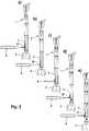
- the shaft 1 with the length adjustment device 3 in a basic position(as in Fig. 1 shown) the same length as one of the shaft segments, for example, the shaft segment 5.
- a prosthesis systemis formed, in which a length adjustable or a solid shaft can be formed by simply replacing the elements 1, 5 as needed.
- Fig. 6-10It is referred to in the Fig. 6-10 illustrated second embodiment. It has a special actuator for the length adjustment. Similar elements are provided with the same reference numerals. From the collar 14 to the other, free end of the shaft 12, an insertion portion 43 extends. This is provided with the external thread 32. It is catchy and the individual threads have a cross-sectional shape that is substantially triangular with a flattened tip. Further, the inner rod except for a short, approximately 1.5 times the diameter of the rod corresponding guide portion 45 has a longitudinal groove 46, at the groove bottom a number of blind holes 47 is formed in a direction parallel to the longitudinal axis line. On the adjusting nut 30 (s. Fig.
Landscapes
- Health & Medical Sciences (AREA)
- Orthopedic Medicine & Surgery (AREA)
- Heart & Thoracic Surgery (AREA)
- Vascular Medicine (AREA)
- Oral & Maxillofacial Surgery (AREA)
- Transplantation (AREA)
- Engineering & Computer Science (AREA)
- Biomedical Technology (AREA)
- Veterinary Medicine (AREA)
- Cardiology (AREA)
- Life Sciences & Earth Sciences (AREA)
- Animal Behavior & Ethology (AREA)
- General Health & Medical Sciences (AREA)
- Public Health (AREA)
- Physical Education & Sports Medicine (AREA)
- Prostheses (AREA)
Description
Translated fromGermanDie Erfindung betrifft eine Prothese zum mindestens teilweisen Ersatz eines Röhrenknochens und eines angrenzenden Gelenks. Sie umfasst einen länglich gestreckten Schaft mit einem ersten und einem zweiten Ende, sowie eine Gelenkeinrichtung, die am zweiten Ende des Schafts angeordnet ist. Es ist eine Längeneinstellrichtung vorgesehen, welche den Schaft längs seiner Achse teleskopartig verschiebt. Die Erfindung erstreckt sich weiter auf ein Prothesenmodülsystem mit auswechselbaren Schäften.The invention relates to a prosthesis for at least partial replacement of a long bone and an adjacent joint. It comprises an elongated shaft having first and second ends, and a hinge means disposed at the second end of the shaft. There is provided a length adjustment direction which telescopically shifts the shaft along its axis. The invention further extends to a prosthesis module system with replaceable stems.
Zum Ersatz von erkrankten oder defekten Knochen und Gelenken sind verschiedene Typen von Endoprothesen seit langem bekannt. Zum Ersatz von Röhrenknochen, insbesondere aufgrund von Tumorerkrankungen, werden Prothesen verwendet, die einen sich über die Länge des zu ersetzenden Knochens ausgedehnten Schaft aufweisen. Der Schaft ersetzt bzw. verstärkt den erkrankten oder fehlenden Bereich des Knochens. Häufig ist er verbunden mit einer Gelenkeinheit, welche ein angrenzendes Gelenk (zum Beispiel Knie oder Ellenbogen) ersetzt. Die Abmessungen des Prothesenschafts müssen daher entsprechend der jeweiligen Anatomie und Pathologie der Patienten gewählt sein.
Zur Anpassung an die individuellen Bedürfnisse ist es bekannt, die Prothesen in verschiedenen Größen anzubieten. Jedoch kann selbst mit einer feinen Abstufung keine optimale Versorgung in Anbetracht der Vielzahl an verschiedenen Bedürfnissen erreicht werden. Dies gilt noch viel mehr bei Patienten, die sich in der Wachstumsphase befinden, also Kindern. Um auch bei solchen Patienten eine ausreichende Versorgung zu ermöglichen, sind Prothesen mit einer Längeneinstelleinrichtung versehen worden. So ist eine Knieprothese bekannt, die einen Schaft und eine Gelenkeinrichtung umfasst, wobei im Schaft eine Teleskopeinrichtung zur Veränderung der Schaftlänge vorgesehen ist (
To adapt to individual needs, it is known to offer the prostheses in different sizes. However, even with a fine gradation, no optimal Supply in view of the variety of different needs to be achieved. This is even more true in patients who are in the growth phase, ie children. In order to allow adequate care even in such patients, prostheses have been provided with a length adjustment. Thus, a knee prosthesis is known which comprises a shaft and a hinge device, wherein a telescopic device is provided in the shaft for changing the shaft length (
Um auch post-operativ die Länge des Schafts einstellen zu können, ist eine weiterentwickelte Prothese bekannt (
Um auch bei der Veränderung der Länge eine Rotation der Prothese, insbesondere eine Rotation von Schaft relativ zum Gelenk, zu vermeiden, kann eine Rotationssperre vorgesehen sein (
Des Weiteren offenbart die
Ein Nachteil dieser bekannten Prothesen liegt darin, dass sie jeweils sehr spezialisiert (post-operativ betätigbar, rotationsgeschützt etc.) sind, und deshalb jeweils nur ein schmales Anwendungsfeld haben.
Der Erfindung liegt die Aufgabe zugrunde, eine Endoprothese der eingangs genannten Art dahingehend weiterzuentwickeln, dass sie universeller einsetzbar ist.A disadvantage of these known prostheses is that they are each very specialized (postoperatively operable, rotation-protected, etc.), and therefore each have only a narrow field of application.
The invention has for its object to further develop an endoprosthesis of the type mentioned in that it is universally applicable.
Die erfindungsgemäße Lösung liegt in den Merkmalen des Anspruchs 1. Vorteilhafte Weiterbildungen sind Gegenstand der abhängigen Ansprüche.
Bei einer Prothese zum mindestens teilweisen Ersatz eines Röhrenknochens und eines angrenzenden Gelenks, umfassend einen länglich gestreckten Schaft mit einem ersten und einem zweiten Ende, eine Gelenkeinrichtung, die am zweiten Ende des Schafts angeordnet ist, wobei eine Längeneinstellrichtung vorgesehen ist, welche den Schaft längs seiner Achse teleskopartig betätigt, ist erfindungsgemäß vorgesehen, dass der Schaft und die Gelenkeinrichtung über komplementäre Steckverbinder gekoppelt sind, wobei die Längeneinstelleinrichtung modular ausgeführt ist und an ihrem proximalen und distalen Ende mit den komplementären Steckverbindern versehen ist, und sie weiter mit einer formschlüssig wirkenden Verdrehsicherung versehen ist. Unter komplementär wird verstanden, dass am einen der beiden Enden ein männlicher und am anderen ein weiblicher Steckverbinder vorgesehen sind. Die Steckverbinder sind Konussteckverbinder.
Kern der Erfindung ist der Gedanke, die Längeneinstelleinrichtung modular auszugestalten und sie dazu an ihrem proximalen und distalen Ende mit genau solchen Steckverbindern zu versehen, die auch am Übergang zwischen Schaft und Gelenk der Prothese angeordnet sind. Die Längeneinstelleinrichtung ist also anders als im Stand der Technik nicht integraler Bestandteil der Prothese, sondern kann nach Bedarf eingesetzt sein. Sie ist sozusagen austauschbar gegen ein herkömmliches Standard-Schaftelement ohne Längeneinstelleinrichtung.The solution according to the invention lies in the features of
In a prosthesis for at least partially replacing a long bone and an adjacent hinge, comprising an elongated shaft having first and second ends, hinge means disposed at the second end of the shaft, wherein a length adjustment direction is provided which guides the shaft along its Axis telescopically actuated, the invention provides that the shaft and the hinge device are coupled via complementary connectors, wherein the length adjustment is modular and is provided at its proximal and distal ends with the complementary connectors, and it is further provided with a form-fitting acting rotation , By complementary is meant that one male and one female connector are provided at one of the two ends. The connectors are cone connectors.
The core of the invention is the idea of modular design the length adjustment and to provide them at its proximal and distal ends with just such connectors, which also at the transition between the shaft and joint the prosthesis are arranged. The Längeneinstelleinrichtung is therefore unlike the prior art is not an integral part of the prosthesis, but can be used as needed. It is, so to speak, interchangeable with a conventional standard shaft element without Längeneinstelleinrichtung.
Die Erfindung ermöglicht es damit auf einfache und effiziente Weise, an sich beliebige Gelenkprothesen mit einer Längeneinstelleinrichtung zu versehen. Die Anpassbarkeit der Prothese an die anatomischen bzw. pathologischen Verhältnisse des einzelnen Patienten verbessert sich damit erheblich, und zwar ohne dass dafür eine Vielzahl von verschiedenen Teilen in unterschiedlicher Größe erforderlich wäre. Die Gelenkeinrichtung kann an sich beliebig ausgeführt sein, wobei sie Bewegungen im Gelenk in unterschiedlichem Grad stützen oder beschränken kann von völlig frei bis zu versteift. Indem die Längeneinstelleinrichtung erfindungsgemäß von der eigentlichen Gelenkprothese getrennt ist dank der modularen Ausführung, kann die Erfindung ohne weiteres auch an anderen Prothesen angewendet sein, solange sie nur über entsprechende Konussteckverbinder verfügen. Dank der integrierten formschlüssig wirkenden Verdrehsicherung sind keine weiteren Anforderungen in Bezug auf Verdrehschutz an die jeweilige Grundprothese gestellt.The invention thus makes it possible in a simple and efficient manner to provide any joint prostheses with a length adjustment device. The adaptability of the prosthesis to the anatomical or pathological conditions of the individual patient thus improves significantly, without the need for a variety of different parts would be required in different sizes. The joint device can be made arbitrary per se, and they can support or limit movements in the joint to varying degrees from completely free to stiffened. By the length adjustment device according to the invention is separated from the actual joint prosthesis thanks to the modular design, the invention can also be readily applied to other prostheses, as long as they have only appropriate Konussteckverbinder. Thanks to the integrated form-locking anti-twist device, there are no further requirements with regard to torsion protection for the respective basic denture.
Die Verdrehsicherung hindert eine unerwünschte relative Verdrehung des Schafts und seiner Komponenten. Die bauliche Integration von Verdrehsicherung und Längeneinstellung hat weiter den Vorteil, dass die Betätigungselemente eng beieinander liegen können. Damit ist zur post-operativen Verstellung nur ein Zugang an einer räumlich eng umgrenzten Stelle erforderlich. Es genügt eine nur minimal invasive Stichinzision, um die Prothese in ihrer Länge zu verändern. Mit einer solch schonenden Operationstechnik ist die Prothese insbesondere auch zur Verwendung bei Kindern geeignet.The anti-rotation prevents unwanted relative rotation of the shaft and its components. The structural integration of anti-rotation and length adjustment has the further advantage that the actuators can be close to each other. Thus, only one access to a spatially narrowed area is required for the post-operative adjustment. It is only a minimally invasive Stitch incision to change the length of the prosthesis. With such a gentle surgical technique, the prosthesis is particularly suitable for use in children.
Vorzugsweise weist der Schaft einen Außen- und einen Innenstab auf, auf welchen die Längeneinstelleinrichtung wirkt. Damit kann mittels eines geeigneten Werkzeugs unmittelbar auf die Längeneinstelleinrichtung eingewirkt werden, die entsprechend den Außenstab teleskopartig gegenüber dem Innenstab verschiebt.Preferably, the shaft has an outer and an inner rod, on which acts the length adjustment. This can be acted upon directly by means of a suitable tool on the length adjustment, which shifts according to the outer rod telescopically relative to the inner rod.
Um trotz der einfachen Verstellbarkeit einen ausreichenden Schutz vor unbeabsichtigter Verstellung zu gewährleisten, ist vorzugsweise eine Doppelsicherung vorgesehen, welche zusätzlich zur Verdrehsicherung eine Verstellsicherung mittels zweier benachbarter Schrauben bildet. Hierbei ist weiter vorzugsweise die eine drehfest am Außenstab und die andere drehbeweglich an der Verstellmutter angeordnet.In order to ensure sufficient protection against inadvertent adjustment despite the simple adjustability, a double safety device is preferably provided, which forms an adjustment by means of two adjacent screws in addition to the rotation. In this case, it is further preferred that one is rotatably mounted on the outer rod and the other is rotatably mounted on the adjusting nut.
Der Außenstab weist mit Vorteil einen Druckflansch auf, der zwei einander gegenüberliegende Bundflächen aufweist, von denen die eine ein Schublager für die Konusverbindung und die andere einen Anschlag für die Längeneinstellung bildet. Damit ist ein sehr kompakter Aufbau ermöglicht, der eine Integration der erfindungsgemäßen Längeneinstelleinrichtung auch an verhältnismäßig kleine Prothesen ermöglicht, beispielsweise zur Anwendung am Ellbogen oder an der Hand.The outer rod advantageously has a pressure flange which has two opposing collar surfaces, one of which forms a thrust bearing for the conical connection and the other a stop for the length adjustment. This allows a very compact construction, which allows integration of the length adjustment device according to the invention also to relatively small prostheses, for example for use on the elbow or on the hand.
Es kann zweckmäßig sein, wenn eine zweite Längeneinstelleinrichtung für den Schaft vorgesehen ist, die vorzugsweise mit invers angeordneten Konusverbindern versehen ist. Bei langen Schäften, insbesondere solchen zum Ersatz des Femurs, kann damit auch am anderen Ende eine Längeneinstellung erfolgen. Dies vergrößert nicht nur den Einstellbereich, sondern ist häufig auch physiologisch günstiger.It may be expedient if a second Längeneinstelleinrichtung is provided for the shaft, which is preferably provided with inwardly arranged cone connectors. For long shafts, especially those for replacement of the femur, can thus be made at the other end a length adjustment. This not only increases the adjustment range, but is often physiologically favorable.
Die Erfindung erstreckt sich weiter auf ein Prothesensystem mit mehreren koppelbaren verschieden langen, insbesondere starren, Schaftelementen, die über die Steckverbinder koppelbar sind, wobei vorzugsweise mindestens eines der insbesondere starren Schaftelemente dieselbe Länge wie die Längeneinstelleinrichtung in ihrer Grundstellung aufweist. Damit können innerhalb eines Prothesensystems solche Prothesen gebildet sein, die einen Schaft mit starrer Länge oder einen Schaft mit einstellbarer Länge aufweisen, wobei durch einfachen Austausch eines starren Schaftmoduls gegen eines mit einstellbarer Länge hin- und hergewechselt werden kann. Dies kann auch intraoperativ erfolgen, so dass je nach Lage des Falls der Chirurg noch im Laufe der Operation entscheiden kann, welche Variante im jeweiligen Fall vorzugsweise verwendet werden soll.The invention further extends to a prosthesis system having a plurality of coupled differently long, in particular rigid, shaft elements which can be coupled via the plug connectors, wherein preferably at least one of the particularly rigid shaft elements has the same length as the length adjustment device in its basic position. Thus, such prostheses can be formed within a prosthetic system, which have a shaft with a rigid length or a shaft with adjustable length, which can be switched back and forth by simply replacing a rigid shaft module against an adjustable length. This can also be done intraoperatively, so that depending on the situation of the case, the surgeon can still decide in the course of the operation, which variant should preferably be used in each case.
Gemäß einer besonders vorteilhaften Variante, die gegebenenfalls unabhängigen Schutz verdient, ist bei einer Prothese zum mindestens teilweisen Ersatz eines Röhrenknochens vorgesehen, dass eine Betätigungseinrichtung für die Längeneinstelleinrichtung mit einem Gewinde auf dem Innenstab und einer auf das Gewinde geschraubte Verstellmutter mit einer umlaufenden Verzahnung vorgesehen ist, wobei am Außenstab eine Lagerbohrung für einen in die umlaufende Verzahnung greifenden Verstellschlüssel vorgesehen ist. Vorzugsweise ist vorgesehen, dass die Verstellmutter mit ihrem oberen Rand abhebbar auf einer Stirnfläche des Außenstabs aufliegt und hinterschnittfrei mit ihm zusammen wirkt.According to a particularly advantageous variant, which may deserve independent protection, it is provided in a prosthesis for at least partial replacement of a long bone that an actuating device for the length adjustment is provided with a thread on the inner rod and an adjusting nut screwed onto the thread with a circumferential toothing, wherein on the outer rod a bearing bore is provided for a cross in the circumferential toothing adjustment. It is preferably provided that the adjusting nut rests with its upper edge liftable on an end face of the outer rod and undercut works with him together.
Kern dieses Erfindungsaspekts ist der Gedanke mittels der Lagerbohrung für den Verstellschlüssel mit einer sehr kleinen und patientenschonenden Zugangsöffnung auszukommen. Damit kann die Länge häufig nachgestellt und - vor allem bei jungen Patienten - dem Wachstum angepasst werden. Dank der modulären Konstruktion ist ein Austausch der Längeneinstelleinrichtung leicht möglich, um - wenn die Verstellung ausgeschöpft ist - eine größere einzusetzen.At the heart of this aspect of the invention is the idea of using the bearing bore for the adjustment key with a very small and patient-friendly access opening. This means that the length can often be readjusted and - especially for young patients - adapted to growth. Thanks to the modular design, replacement of the length adjustment device is easily possible in order to use a larger one when the adjustment is exhausted.
Dank der vorzugsweise frei gelagerten Verstellmutter ist eine axiale Verschieblichkeit gegenüber dem Außenstab gegeben, nämlich indem die Verstellmutter an dessen Stirnseite nur aufliegt, ohne dort mittels einer formschlüssigen Führung, insbesondere einem Hinterschnitt, gesichert zu sein; die Verstellmutter kann damit von dem Außenstab frei wegbewegt werden.Thanks to the preferably freely mounted adjusting nut, an axial displaceability relative to the outer rod is given, namely by the adjusting nut only rests on the front side, without being secured there by means of a positive guide, in particular an undercut; the adjusting nut can thus be moved away from the outer rod free.
Mit dieser Konstruktion werden zwei wesentliche Vorteile verknüpft. Zum einen wird damit erreicht, dass die Prothesenteile voneinander getrennt werden können. Die zur Implantation der Röhrenknochenprothese erforderliche Wundöffnung kann damit kleiner ausfallen. Für den Patienten ist dies deutlich schonender, und für den Chirurgen ist das leichter zu handhaben.This construction combines two major benefits. On the one hand, this ensures that the prosthesis parts can be separated from one another. The wound opening required for implantation of the long bone prosthesis can thus be smaller. For the patient, this is much gentler and easier for the surgeon to handle.
Ein weiterer Vorteil besteht darin, dass bedingt durch das Merkmal der hinterschnittfreien Lagerung der Verstellmutter eine größere Kraftauflagefläche zwischen Verstellmutter und dem Außenstab an der Stirnseite ermöglicht ist. Die Prothese ist dank der größeren Kraftauflagefläche somit weniger belastet bzw. sie kann bei gleicher Robustheit kleiner und damit schlanker ausgeführt sein. Gerade letzteres bietet einen erheblichen Vorteil zur Implantation bei jungen Patienten.Another advantage is that due to the feature of undercut bearing the adjusting nut a larger force bearing surface between the adjusting nut and the outer rod is made possible on the front page. The prosthesis is thus less loaded thanks to the larger force bearing surface or they can be made smaller and thus slimmer with the same robustness. Especially the latter offers a significant advantage for implantation in young patients.
Zwar ist es bekannt, bei einer Prothese zum Ersatz eines Röhrenknochens mit angrenzendem Gelenk in dem Übergang zwischen Gelenk und Röhrenknochen ein Kegelradgetriebe zur Längenverstellung des Röhrenknochenersatzes vorzusehen (
Die erfindungsgemäße Prothese ist damit wesentlich schonender für den Patienten und günstiger in Bezug auf das Wachstumsverhalten, und ist somit insbesondere zur Behandlung von jungen Patienten (Kindern) in der Wachstumsphase geeignet. Denn bei der Implantation muss häufig die Wachstumslage des Knochens reseziert werden. Sie ist aber auch durchaus geeignet zur Anwendung bei Erwachsenen, wenn sich post-operativ Veränderungen ergeben, beispielsweise auf Grund von Längungen im Bandapparat.The prosthesis according to the invention is thus much gentler on the patient and more favorable in terms of growth behavior, and is therefore particularly suitable for the treatment of young patients (children) in the growth phase. Because during implantation often the growth position of the bone must be resected. But it is also quite suitable for use in adults, if post-operative changes arise, for example, due to elongations in the ligaments.
Die umlaufende Verzahnung ist vorzugsweise als Steilverzahnung ausgeführt. Unter Steilverzahnung wird verstanden, dass die lasttragenden Flanken einen Flankenwinkel von mindestens 50° bis höchstens 85°, vorzugsweise mindestens 60° aufweisen. Mit einer solchen steilen Ausrichtung der Last tragenden Flanken wird die Ausbildung einer Axialkraft durch das Betätigen des Verstellschlüssels und dessen Einwirkung auf die umlaufende Verzahnung der Verstellmutter unterdrückt bzw. weitgehend vermieden. Eine unerwünschte parasitäre Längenverstellung oder eine unerwünschte axiale Verschiebung auf Grund des Verstellschlüssels kann damit vermieden werden. Es ist somit sichergestellt, dass die Längenverstellung allein aus der über die Drehbewegung der Verstellmutter übertragenen Axialverschiebung auf Grund der Gewindesteigung des Innengewindes der Verstellmutter beruht.The circumferential toothing is preferably designed as a steep toothing. By steep teeth is understood that the load-bearing flanks have a flank angle of at least 50 ° to at most 85 °, preferably at least 60 °. With such a steep orientation of the load-bearing flanks the formation of an axial force is suppressed by the actuation of the adjusting key and its action on the peripheral toothing of the adjusting nut or largely avoided. An undesirable parasitic length adjustment or an undesired axial displacement due to the Verstellschlüssels can be avoided. It is thus ensured that the length adjustment is based solely on the transmitted via the rotational movement of the adjusting axial displacement due to the thread pitch of the internal thread of the adjusting nut.
Vorzugsweise ist die Verzahnung in einem entsprechend umlaufenden Rezess eingebettet. Der Rezess ist dabei vorzugsweise an der Außenkante der Oberseite ausgebildet. Damit wird erreicht, dass die umlaufende Verzahnung nicht übersteht, also dass keine Spitzen in Axialrichtung vorragen.Preferably, the toothing is embedded in a corresponding circumferential recess. The recess is preferably formed on the outer edge of the top. This ensures that the circumferential toothing does not protrude, so that no peaks protrude in the axial direction.
Damit wird der Gefahr einer Irritation umliegenden Gewebes auf wirksame Weise begegnet.This effectively counteracts the risk of irritation to surrounding tissue.
Für alle Ausführungsformen gilt außerdem:For all embodiments also applies:
Mit Vorteil ist das Innengewinde der Verstellmutter eingängig. Unter "eingängig" wird hierbei verstanden, dass es nur einen Gewindegang gibt, der von einer Seite der Mutter zur gegenüberliegenden Seite durchläuft. Mit der Eingängigkeit wird eine definierte Positionierung der Verstellmutter in Drehrichtung in Bezug auf den Innenstab erreicht. Dies erleichtert eine präzise Ausrichtung und damit Längenverstellung. Die Gefahr von positionsmäßigen Doppeldeutigkeiten besteht damit nicht.Advantageously, the internal thread of the adjusting nut is catchy. By "catchy" is meant that there is only one thread passing through from one side of the nut to the opposite side. With the accessibility a defined positioning of the adjusting nut in the direction of rotation is achieved with respect to the inner rod. This facilitates precise alignment and thus length adjustment. The danger of positional ambiguities does not exist.
Vorzugsweise ist das Gewinde des Innenstabs geplant. Unter "geplant" wird hierbei verstanden, dass die Spitzen des Gewindes an dem Innenstab gebrochen sind, also nicht im eigentlichen Sinne spitz sind, sondern durch eine vorzugsweise ebene Fläche ersetzt sind. Diese ebene Fläche bildet in ihrer Gesamtheit einen Hohlzylindermantel. Das Gewinde des Innenstabs wirkt damit gegenüber seiner Umgebung weniger scharfkantig. Die Gefahr von Irritationen wird damit verringert.Preferably, the thread of the inner rod is planned. By "planned" is here understood that the tips of the thread are broken on the inner rod, so are not pointed in the strict sense, but are replaced by a preferably flat surface. This flat surface forms in its entirety a hollow cylinder shell. The thread of the inner rod thus acts with respect to its surroundings less sharp-edged. The risk of irritation is thus reduced.
Mit Vorteil weist die Verstellmutter eine polierte Umfangsfläche auf. Hiermit wird eine negative Wirkung des umliegenden Gewebes auf die Verstellmutter vermieden, so dass es kaum zu Anhaftungen kommt. Die Verstellmutter bleibt damit auch nach mehrjähriger Implantationsdauer verstellbar, und wird nicht durch anwachsendes Gewebe (Bindegewebe) blockiert. Die polierte Umfangsfläche kann auch durch eine andere Oberflächengestaltung erreicht sein, welche zu einer Verringerung von Anhaftungen führt. In Betracht kommt eine Anodisierung der Oberfläche, insbesondere bei Endoprothesen aus Titan.Advantageously, the adjusting nut has a polished peripheral surface. Hereby, a negative effect of the surrounding tissue is avoided on the adjusting nut, so that it hardly comes to adhesions. The adjusting nut thus remains adjustable even after several years of implantation, and is not blocked by growing tissue (connective tissue). The polished peripheral surface can also be achieved by a different surface design, which leads to a Reduction of buildup leads. Anodization of the surface is possible, in particular in the case of endoprostheses made of titanium.
Die Verstellmutter weist zweckmäßigerweise an ihrer Umfangsfläche eine Mehrzahl von Radiallöchern auf, die vorzugsweise einen gleichmäßigen Winkelabstand aufweisen. Diese Radiallöcher dienen zur Aufnahme eines Verstellstifts. Dieser wird in eines dieser Löcher eingesteckt, so kann die Verstellmutter um einen bestimmten Winkelbetrag verdreht werden, bis der Verstellstift seinen Anschlag erreicht. Durch Umstecken in eines der anderen, vorzugsweise winkelgleich angeordneten Radiallöcher kann der Verstellstift erneut betätigt werden, so dass im Ergebnis eine Verdrehung der Verstellmutter und damit eine Längenverstellung erreicht ist. Dies bietet auch den Vorzug einer Notbetätigung, falls die Längeneinstelleinrichtung mittels Verstellschlüssel nicht betätigt werden kann.The adjusting nut expediently has on its peripheral surface a plurality of radial holes, which preferably have a uniform angular distance. These radial holes serve to receive an adjusting pin. This is inserted into one of these holes, so the adjusting nut can be rotated by a certain angle, until the adjusting pin reaches its stop. By moving into one of the other, preferably equiangularly arranged radial holes of the adjusting pin can be actuated again, so that as a result, a rotation of the adjusting nut and thus a length adjustment is achieved. This also offers the advantage of an emergency operation, if the length adjustment can not be operated by means of adjustment.
Die Verstellmutter weist zweckmäßiger Weise eine abgerundete Tastmarkierung auf. Damit ist es ermöglicht, eine "Nulllage" der Verstellmutter in Drehrichtung definiert festzulegen. Dies ist zweckmäßig bei einer rechnerischen Übertragung der nachzustellenden Länge bzw. des Längenwachstums, und zwar gemessen in Umdrehungen der Verstellmutter. Um hier eine Nullposition zu haben, ist die Tastmarkierung ein großer Vorteil. Zweckmäßigerweise weist der Außenstab, gegen dessen Stirnseite die Verstellmutter anliegt, eine formgleiche Fortsetzung der Tastmarkierung auf. Damit ergibt sich ein harmonischer Übergang zwischen der Tastmarkierung auf der Verstellmutter und der Fortsetzung auf dem Außenstab. Der Gefahr von Irritationen umliegenden Gewebes wird damit wirksam begegnet.The adjusting nut expediently has a rounded Tastmarkierung. This makes it possible to define a "zero position" of the adjusting nut defined in the direction of rotation. This is expedient for a mathematical transmission of the length to be readjusted or the length growth, measured in revolutions of the adjusting nut. To have a zero position here, the tactile mark is a great advantage. Conveniently, the outer rod, against the front side of the adjusting nut is applied, a shape of the same continuation of the Tastmarkierung. This results in a harmonious transition between the Tastmarkierung on the adjusting nut and the continuation on the outer rod. The risk of irritation surrounding tissue is thus effectively countered.
Mit Vorteil sind an dem Innenstab Vertiefungen vorgesehen, in die ein an dem Außenstab angeordnetes Verriegelungselement eingreift. Bei diesen Vertiefungen kann es sich um eine Reihe von Bohrungen handeln, die an der Außenseite des Schafts angeordnet sind. Zweckmäßigerweise sind sie in einer Axialnut angeordnet. Sie dienen dazu, dass eine Schraube eingedreht ist, welche mit ihrer Spitze in die Vertiefung eingreift und damit den Innenstab gegenüber einer ungewollten Bewegung in axialer Richtung sichert. Damit wird eine unbeabsichtigte Trennung von Innenstab und Außenstab sicher vermieden. Dieser kann damit entgegen gewirkt werden. Mit Vorteil ist die Befestigungsschraube als eine Madenschraube ausgeführt. Sie benötigt wenig Platz und kann dennoch eine ausreichend sichere Arretierung der Längeneinstelleinrichtung erreichen.Advantageously, depressions are provided on the inner rod into which engages a locking element arranged on the outer rod. These recesses may be a series of holes located on the outside of the shaft. Appropriately, they are arranged in an axial groove. They serve to screw in a screw, which engages with its tip in the recess and thus secures the inner rod against unwanted movement in the axial direction. Thus, an inadvertent separation of the inner rod and outer rod is reliably avoided. This can be counteracted. Advantageously, the fastening screw is designed as a grub screw. It requires little space and yet can achieve a sufficiently secure locking the length adjustment.
Vorzugsweise besteht mindestens eines der beiden Elemente, das Gewinde des Innenstabs und/oder das Innengewinde der Verstellmutter aus titanfreiem Material, insbesondere Cobalt-Chrom-Material. Es bietet den Vorzug, dass es gerade im Zusammenspiel mit - dem im Prothesenbau bevorzugten Material - Titan nicht zum Festgehen des Gewindes kommt. Ein Schutz gegenüber einer unbeabsichtigten Blockade des Gewindes insbesondere durch Festgehen ist ein erheblicher Vorteil für die erfindungsgemäße Röhrenknochenprothese, deren wichtigste Eigenschaft die Längsverschieblichkeit ist.
Die Erfindung wird nachfolgend unter Bezugnahme auf die beigefügte Zeichnung erläutert, in der vorteilhafte Ausführungsbeispiele dargestellt sind. Es zeigen:
- Fig. 1
- eine Schnittansicht für eine Kniegelenkprothese gemäß einem ersten Ausführungsbeispiel der Erfindung;
- Fig. 2
- eine Totalprothese auf Grundlage des ersten Ausführungsbeispiels gemäß
Fig. 1 in Frontal und Lateralansicht; - Fig. 3
- Explosionsansichten zu
Fig. 2 ; - Fig. 4
- eine Schnittansicht zu einer Variante;
- Fig. 5a-e
- Darstellungen zur Durchführung einer Längenverstellung;
- Fig. 6
- eine Explosionsansicht eines zweiten Ausführungsbeispiels der Erfindung;
- Fig. 7a-c
- vergrößerte Detaildarstellungen zum zweiten Ausführungsbeispiel;
- Fig. 8
- eine Funktionsdarstellung eine Längeneinstelleinrichtung;
- Fig. 9
- eine Darstellung im montierten Zustand; und
- Fig. 10
- eine perspektivische Ansicht.
The invention will be explained below with reference to the accompanying drawings, in which advantageous embodiments are shown. Show it:
- Fig. 1
- a sectional view of a knee joint prosthesis according to a first embodiment of the invention;
- Fig. 2
- a total prosthesis based on the first embodiment according to
Fig. 1 in frontal and lateral view; - Fig. 3
- Exploded views too
Fig. 2 ; - Fig. 4
- a sectional view of a variant;
- Fig. 5a-e
- Illustrations for performing a length adjustment;
- Fig. 6
- an exploded view of a second embodiment of the invention;
- Fig. 7a-c
- enlarged detail views to the second embodiment;
- Fig. 8
- a functional representation of a length adjustment;
- Fig. 9
- a representation in the assembled state; and
- Fig. 10
- a perspective view.
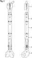
In
Der Schaft 1 umfasst einen Außenstab 11 und einen Innenstab 12, der teleskopartig längs seiner Mittelachse 10 verschieblich in dem Außenstab 11 geführt ist. Der Außenstab 12 weist an seinem ersten Ende einen weiblichen Konussteckverbinder 19 auf, der bei Bedarf zum Ankoppeln weiterer Stabsegmente (in
Die Längeneinstelleinrichtung 3 umfasst die Verstellmutter 30 mit einem eingängigen Innengewinde 39, das mit einem auf dem Innenstab 12 angeordneten eingängigen Stellgewinde 32 kämmt. Die Verstellmutter 30 weist an ihren Seitenflächen eine Mehrzahl von Eingriffsöffnungen 31 auf, die als Radialbohrungen ausgestaltet sind. Sie sind dazu ausgebildet, einen Stift 9 (s.
Zur Fixierung einer eingestellten Länge sind Sicherungseinrichtungen vorgesehen. Sie umfassen eine Verstellsicherung 35 und eine Verdrehsicherung 37. Die Verstellsicherung 35 weist eine Klemmschraube auf, die in eine der radialen Bohrungen 31 der Verstellmutter 30 eingesetzt ist und mit ihrer Spitze auf eine Abflachung 15 am Außenstab 12 einwirkt. Damit wird eine formschlüssige Verriegelung der Verstellmutter 30 erreicht. Es besteht so Sicherheit, dass auch bei großer Last und häufigen Lastwechseln keine unbeabsichtigte Verdrehung der Verstellmutter 30 mit entsprechender Längenänderung entstehen kann. Die Verdrehsicherung 37 ist ähnlich aufgebaut und weist eine Fixierschraube auf, die in eine Radialbohrung im Bereich des Stirnflansch 13 am Außenstab angeordnet ist. Die Fixierschraube wirkt mit ihrer Spitze in den Bereich des Gegengewindes 32 und sichert damit den Außenstab 11 vor einer Verdrehung gegenüber dem Innenstab 12. Dieser ist wiederum über eine an sich bekannte Konussicherung 27 mittels zweier diametral gegenüberliegender Fixierschrauben an einer unerwünschten Verdrehung gegenüber der Gelenkeinrichtung 2 gehindert. Damit ergibt sich eine durchgehende Rotationssicherung von der Gelenkeinrichtung 2 über die Längeneinstelleinrichtung 3 bis zum Schaft 1.To fix a set length safety devices are provided. They include an
Der Vorgang der Längenverstellung ist in
Bei der in
Eine Ausführungsvariante ist in
Es wird Bezug genommen auf das in den
An der Verstellmutter 30 (s.
Die Verstellmutter weist an ihrem oberen Rand eine umlaufende Verzahnung 81 auf, die Teil einer Betätigungseinrichtung 8 ist. Die Verzahnung 81 hat ein wellenförmiges Profil mit abgerundeten Spitzen 82 und Tälern 83. Die die Spitzen 82 und Täler 83 verbindenden Flanken 84 sind als Steilflanken ausgeführt und haben in ihrem Mittelteil eine Steigung (bezogen auf die durch den oberen Rand 56 definierte Radialebene) von 60 Grad. Die Täler 83 steigen von außen nach innen an, so dass sich eine kegelig zulaufendes Zahnstruktur ergibt, wie sie insbesondere für einen Winkeltrieb geeignet ist. Die Verzahnung 81 ist an einem an der Außenseite des oberen Rands 56 umlaufenden Rezess 80 so angeordnet, dass die Spitzen 82 nicht hinausragen, sondern bündig mit der durch den oberen Rand definierten Ebene abschließen (s.
On the adjusting nut 30 (s.
The adjusting nut has at its upper edge a circumferential toothing 81, which is part of an
Der Stirnflansch 13 des Außenstabs 11 ist im Wesentlichen plan, insbesondere ist er hinterschnittfrei, d. h. an keiner Stelle ist ein Hinterschnitt ausgebildet. Am Außenmantel des Außenstabs 11 ist benachbart zum Rand eine zweite Erhebung 51 angeordnet. Sie ist mit einer Radialbohrung 38 versehen, die als Lagersitz für einen Verstellschlüssel 89 der Betätigungseinrichtung 8 fungiert. Der Abstand zwischen der Radialbohrung 38 und dem Stirnflansch 13 ist auf die Abmessungen des Verstellschlüssel 89 abgestimmt, wie nachfolgend näher beschrieben ist.The
An dem Außenstab 11 kann eine Madenschraube 37 als Verriegelungsinstrument vorgesehen sein. Vorzugsweise ist sie in die Lagerbohrung 38 einschraubbar und ragt mit ihrer Spitze im eingeschraubten Zustand in die Längsnut 46, genauer gesagt eines der Sacklöcher 47, und sichert den Innenstab 12 damit gegenüber unerwünschten Luxationsbewegungen.On the
Der Verstellschlüssel 89 ist aufgebaut wie ein Kegeltriebschlüssel, wie er zur Betätigung von Spannfuttern bekannt ist. Es weist an seinem hinteren Ende einen Betätigungsgriff 88 auf, wobei es sich im einfachsten Fall um eine Querstange handeln kann. Am vorderen Ende ist eine Kegelverzahnung 86 vorgesehen, die so beschaffen ist, um mit der Verzahnung 81 an der der Verstellmutter 30 zu kämmen. Um die Kegelverzahnung 86 in Eingriff mit der Verzahnung 81 zu bringen, ist an der vorderen Spitze ein Lagerzapfen 87 ausgebildet, der komplementär zu der Radialbohrung 38 ausgeführt ist, so dass ein Drehlager gebildet ist. Der Abstand der Radialbohrung 38 von dem Stirnflansch 13 ist so auf den Durchmesser der Kegelverzahnung 96 abgestimmt, dass bei in die Radialbohrung 38 eingestecktem Verstellschlüssel 89 die Kegelverzahnung 86 in Eingriff mit der Verzahnung 81 der Verstellmutter 30 ist, die bündig mit ihrem oberen Rand an dem Stirnflansch 13 des Außenstabs 11 anliegt.The adjustment key 89 is constructed as a bevel drive key, as he is known for the operation of chucks is. It has at its rear end to an
Die Betätigungseinrichtung 8 wird wie folgt betätigt. Im Ausgangszustand ist die Verstellmutter 30 auf das Außengewinde 32 des Innenstabs 12 aufgeschraubt. Er ist soweit in den Außenstab 11 eingeschoben, bis die Verstellmutter 30 mit ihrem oberen Rand bündig an dem Stirnflansch 13 des Außenstabs 11 anliegt. Durch Drehen des in die Lagerbohrung 31 eingesteckten Verstellschlüssel 89 kämmt dessen Kegelverzahnung 86 mit der Verzahnung 81 der Verstellmutter 30, wodurch sich diese dreht und der Innenstab 12 aus dem Außenstab 11 herausgeschoben wird. Der Betrag der Schiebestrecke ist hierbei bestimmt durch die Steigung des mit der Verstellmutter 30 zusammenwirkenden Außengewindes 32 und dem Übersetzungsverhältnis zwischen Kegelverzahnung 86 und der Verzahnung 81. Bei der Verstellung bleibt die Verstellmutter 30 in Anlage an dem Außenstab 11.The
Tritt aufgrund des Wachstums des Patienten (oder einer Längung stützender Bänder) eine Verlängerung des Oberschenkels auf, kann die erfindungsgemäße Endoprothese daran angepasst werden. Dies geschieht, indem die Verstellmutter 30 nachgestellt wird. Dazu braucht nur mittels eines kleinen und damit Patienten schonenden Eingriffs das Antriebswerkzeug 89 in die Lagerbohrung 38 eingesetzt zu werden, und durch Drehen wird die Verstellmutter 30 nachgestellt. Der Nachstellweg ist die durch die Anzahl der Umdrehungen des Verstellschlüssels 89 eindeutig bestimmt. Um die Anzahl der Umdrehungen leicht nachkontrollieren zu können, dient die Tastmarkierung 55 an der Verstellmutter 30. In der Ausgangslage fluchtet sie mit der gleichartigen Erhebung 51 an dem Außenstab 11, und steht immer dann, wenn die Verstellmutter 30 eine vollständige Drehung durchlaufen hat, wieder in fluchtender Position. Damit kann die korrekte Positionierung leicht durch Tasten auch von außen überprüft werden.If an extension of the thigh occurs due to the growth of the patient (or an elongation of supporting ligaments), the endoprosthesis according to the invention can be adapted thereto. This is done by the adjusting
Um auch nach längerer Implantationszeit eine einwandfreie Funktion der Betätigungseinrichtung 8 zu gewährleisten, sind ein Verzahnungschutzring 50 mit einer Anformung 52 für die Kegelverzahnung 86 des Verstellschlüssels 89 und eine Multiabdeckung 53 mit mehreren (im dargestellten Ausführungsbeispiel drei) Zapfenstumpfen 54 vorgesehen (s.
Bei der in
Claims (20)
- Prosthesis for at least partial replacement of a tubular bone and of an adjoining joint, comprising
an elongate shaft (1) with a first end and a second end, and
a joint mechanism (2) arranged at the second end of the shaft (1),
wherein the shaft (1) and the joint mechanism (2) are coupled via complementary conical plug connectors (18, 29),
the shaft has an inner rod (12) and a coaxial outer rod (11),
a length-adjusting mechanism (3) is provided which actuates the shaft (1) along its axis (10) in the manner of a telescope and acts on the inner rod (12) and the outer rod (11), wherein
the length-adjusting mechanism (3) is of a modular design and is provided, at its proximal and its distal end, with complementary conical plug connectors (18, 19), wherein
the length-adjusting mechanism is further provided with an anti-rotation means (37) acting in form-fit engagement,
characterized in that a male conical plug connector is provided at one of the two ends of the length-adjusting mechanism (3) and a female conical plug connector is provided at the other of the two ends,in that the anti-rotation means (37) is arranged on the outer rod (11) and engages in a longitudinal recess (15) on the inner rod (12), andin that
the inner rod (12) is prevented from rotation with respect to the joint mechanism (2) by means of two radially opposite fixing screws. - Prosthesis according to Claim 1,characterized in that a dual securing mechanism is provided which comprises an adjustment lock (35) in addition to the anti-rotation means (37).
- Prosthesis according to Claim 2,characterized in that the anti-rotation means (37) is fixed in rotation, and the adjustment lock (35) is arranged rotatably.
- Prosthesis according to one of the preceding claims,characterized in that a compression flange (15) is provided which has two opposite collar faces, one of which is a thrust bearing for the plug connectors, and the other forms a stop for the length adjustment.
- Prosthesis according to one of the preceding claims,characterized in that a second length-adjusting mechanism (3') is provided for the shaft (1).
- Prosthesis according to one of the preceding claims,characterized in that the length-adjusting mechanism (3) has a screw drive (30, 32) which is encapsulated in the starting position.
- Prosthesis according to one of the preceding claims,characterized in that an actuation mechanism (8) for the length-adjusting mechanism (3) having a thread (32) on the inner rod (12) and an adjustment nut (30) screwed onto the thread (32) is provided with a circumferential toothing (81), wherein a bearing bore (38) is provided on the outer rod (11) for an adjusting wrench (89) engaging in the circumferential toothing (81).
- Prosthesis according to Claim 7,characterized in that the adjustment nut (30) lies with its upper edge liftably on a front flange (13) of the outer rod (11) and cooperates therewith without undercut.
- Prosthesis according to Claim 7 or 8,characterized in that the circumferential toothing (81) is designed as a steep toothing, the load-bearing flanks (84) of which have a flank angle of at least 50 degrees to at most 85 degrees, preferably at least 60 degrees.
- Prosthesis according to Claim 7, 8 or 9,characterized in that the toothing (81) is arranged in a circumferential recess (80).
- Prosthesis according to one of the preceding claims,characterized in that a protective ring (50), preferably made of resilient plastic, is provided which is arranged between adjustment nut (30) and front flange (13) and covers the toothing (81) on the outside.
- Prosthesis according to one of the preceding claims,characterized in that the internal thread (39) of the adjustment nut (30) is a single-start thread.
- Prosthesis according to one of the preceding claims,characterized in that the thread (32) of the inner rod (12) is flattened.
- Prosthesis according to one of the preceding claims,characterized in that the adjustment nut (30) has a polished jacket face.
- Prosthesis according to one of the preceding claims,characterized in that the adjustment nut (30) has on its jacket surface a plurality of radial holes (57), preferably at uniform angular intervals.
- Prosthesis according to one of the preceding claims,characterized in that the adjustment nut (30) has a rounded tactile marking (55) which is continued, preferably identically in shape, on the outer rod (11).
- Prosthesis according to one of the preceding claims,characterized in that a plurality of depressions (47) are provided on the inner rod (12), into which depressions (47) a locking element (37) arranged on the outer rod (11) engages.
- Prosthesis according to one of the preceding claims,characterized in that the thread (32) and/or the internal thread (39) are composed of titanium-free material, particularly cobalt-chromium material.
- Prosthesis system comprising a prosthesis, according to one of the preceding claims, and a plurality of shaft elements (5, 6) which are of different lengths and can be coupled via the plug connectors.
- Prosthesis system according to Claim 19,characterized in that one of the shaft elements (5, 6) is the same length as the length-adjusting mechanism (3) in its starting position.
Priority Applications (1)
| Application Number | Priority Date | Filing Date | Title |
|---|---|---|---|
| EP11724563.9AEP2579815B1 (en) | 2010-06-11 | 2011-06-10 | Prosthetic for partial replacement of a long bone |
Applications Claiming Priority (3)
| Application Number | Priority Date | Filing Date | Title |
|---|---|---|---|
| EP10006098AEP2394606A1 (en) | 2010-06-11 | 2010-06-11 | Prosthetic for partial replacement of a long bone |
| EP11724563.9AEP2579815B1 (en) | 2010-06-11 | 2011-06-10 | Prosthetic for partial replacement of a long bone |
| PCT/EP2011/002875WO2011154156A1 (en) | 2010-06-11 | 2011-06-10 | Prosthesis for partial replacement of a tubular bone |
Publications (2)
| Publication Number | Publication Date |
|---|---|
| EP2579815A1 EP2579815A1 (en) | 2013-04-17 |
| EP2579815B1true EP2579815B1 (en) | 2017-04-05 |
Family
ID=43033053
Family Applications (2)
| Application Number | Title | Priority Date | Filing Date |
|---|---|---|---|
| EP10006098AWithdrawnEP2394606A1 (en) | 2010-06-11 | 2010-06-11 | Prosthetic for partial replacement of a long bone |
| EP11724563.9AActiveEP2579815B1 (en) | 2010-06-11 | 2011-06-10 | Prosthetic for partial replacement of a long bone |
Family Applications Before (1)
| Application Number | Title | Priority Date | Filing Date |
|---|---|---|---|
| EP10006098AWithdrawnEP2394606A1 (en) | 2010-06-11 | 2010-06-11 | Prosthetic for partial replacement of a long bone |
Country Status (16)
| Country | Link |
|---|---|
| US (1) | US20130085577A1 (en) |
| EP (2) | EP2394606A1 (en) |
| JP (1) | JP2013528079A (en) |
| KR (1) | KR101493922B1 (en) |
| CN (1) | CN103002834B (en) |
| AU (1) | AU2011264072B2 (en) |
| BR (1) | BR112012031551B1 (en) |
| CA (1) | CA2802078C (en) |
| CO (1) | CO6670534A2 (en) |
| ES (1) | ES2628585T3 (en) |
| IL (1) | IL223465B (en) |
| MX (1) | MX2012014484A (en) |
| RU (1) | RU2532891C2 (en) |
| UA (1) | UA111159C2 (en) |
| WO (1) | WO2011154156A1 (en) |
| ZA (1) | ZA201209348B (en) |
Families Citing this family (22)
| Publication number | Priority date | Publication date | Assignee | Title |
|---|---|---|---|---|
| EP2394606A1 (en)* | 2010-06-11 | 2011-12-14 | WALDEMAR LINK GmbH & Co. KG | Prosthetic for partial replacement of a long bone |
| US9532879B2 (en) | 2012-09-20 | 2017-01-03 | Depuy Ireland Unlimited Company | Femoral knee prosthesis system with augments and multiple lengths of sleeves sharing a common geometry |
| US8998996B2 (en)* | 2012-09-20 | 2015-04-07 | Depuy (Ireland) | Knee prosthesis system with standard and distal offset joint line |
| US9320603B2 (en) | 2012-09-20 | 2016-04-26 | Depuy (Ireland) | Surgical instrument system with multiple lengths of broaches sharing a common geometry |
| FR3001122B1 (en)* | 2013-01-23 | 2015-02-27 | Euros Sa | AUTOMATIC ELONGATION IMPLANT |
| CN103117018B (en)* | 2013-01-29 | 2015-12-23 | 营口巨成教学科技开发有限公司 | Simulation architecture of bone movement |
| DE102013101325B4 (en)* | 2013-02-11 | 2016-11-17 | Merete Medical Gmbh | Intermediate body for an endoprosthesis and Endoprothesenanordnung |
| JP6521671B2 (en)* | 2014-02-27 | 2019-05-29 | 京セラ株式会社 | Total knee arthroplasty tibial trial |
| CN104921796B (en)* | 2015-07-08 | 2017-06-20 | 西安交通大学 | A kind of tumorous type knee-joint prosthesis intramedullary needle |
| EP3248552A1 (en)* | 2016-05-25 | 2017-11-29 | WALDEMAR LINK GmbH & Co. KG | Tool for the production of a recess in bone tissue |
| EP3381410A1 (en)* | 2017-03-31 | 2018-10-03 | Waldemar Link GmbH & Co. KG | Connection sleeve for two anchoring shafts of two side-to-side prostheses |
| US20180353227A1 (en)* | 2017-06-07 | 2018-12-13 | Clarkson University | Adjustable length orthopedic device |
| CN108992156B (en)* | 2018-09-07 | 2024-03-15 | 北京爱康宜诚医疗器材有限公司 | Bone connector |
| CN110840632B (en)* | 2019-12-02 | 2025-08-01 | 北京爱康宜诚医疗器材有限公司 | Knee joint prosthesis |
| CN110840628B (en)* | 2019-12-02 | 2025-08-01 | 北京爱康宜诚医疗器材有限公司 | Hip joint prosthesis |
| CN111053633A (en)* | 2019-12-30 | 2020-04-24 | 北京力达康科技有限公司 | An extendable medulla needle for pediatric patient replacement surgery and method of using the same |
| CN111789702A (en)* | 2020-07-15 | 2020-10-20 | 北京力达康科技有限公司 | A child-type tumor joint prosthesis with preservation of femoral neck and knee joint surface |
| CN113101016B (en)* | 2021-05-13 | 2022-08-16 | 北京爱康宜诚医疗器材有限公司 | Prosthesis connecting element and prosthesis assembly |
| CN113367851A (en)* | 2021-05-22 | 2021-09-10 | 北京力达康科技有限公司 | Length-adjustable hip joint prosthesis |
| CN116019612B (en)* | 2023-03-30 | 2023-07-14 | 北京爱康宜诚医疗器材有限公司 | Semi-elbow joint prosthesis |
| CN117137691B (en)* | 2023-09-11 | 2024-05-03 | 南方医科大学珠江医院 | Tibia extension rod eccentric adjusting instrument |
| WO2025166409A1 (en)* | 2024-02-08 | 2025-08-14 | Signature Orthopaedics Europe Ltd | Torsion locking interface for an orthopaedic implant taper interlock |
Family Cites Families (16)
| Publication number | Priority date | Publication date | Assignee | Title |
|---|---|---|---|---|
| GB2094629B (en) | 1981-03-14 | 1984-08-01 | Tsnii | Artifical hip knee and femur |
| US4578081A (en)* | 1982-02-17 | 1986-03-25 | Howmedica International, Inc. | Bone prosthesis |
| DE3336004C2 (en)* | 1983-10-04 | 1986-10-16 | S + G Implants GmbH, 2400 Lübeck | Adapter for a bone endoprosthesis |
| US4502160A (en) | 1983-10-27 | 1985-03-05 | Dow Corning Wright | Adjustable length prosthetic joint implant |
| SU1373402A1 (en)* | 1986-06-02 | 1988-02-15 | Латвийский Научно-Исследовательский Институт Травматологии И Ортопедии | Endoprosthesis of tubular bone |
| DE8706999U1 (en)* | 1987-05-15 | 1987-07-23 | Howmedica GmbH, 2314 Schönkirchen | Endoprosthesis for femoral or tibial joint bone parts and adjacent bone sections |
| DE3801593A1 (en) | 1988-01-21 | 1989-08-03 | Hemscheidt Maschf Hermann | GROUP CONTROL FOR HYDRAULIC SCREAM EXTENSION |
| FR2666221B1 (en)* | 1990-09-04 | 1997-11-21 | Gilles Missenard | PROSTHETIC GROWTH MODULE, EXTENSIBLE. |
| DE4039064A1 (en)* | 1990-12-07 | 1992-06-11 | Eska Medical Gmbh & Co | DEVICE FOR ADAPTING THE LENGTH OF AN ENDOPROTHESIS FOR TUBE BONES |
| US5387239A (en)* | 1993-04-19 | 1995-02-07 | Wright Medical Technology, Inc. | Adjustable length prosthetic implant |
| US6494913B1 (en)* | 1998-03-17 | 2002-12-17 | Acumed, Inc. | Shoulder prosthesis |
| DE59913637D1 (en)* | 1999-09-24 | 2006-08-10 | Link Waldemar Gmbh Co | Alloplastic replacement for a long bone |
| GB2370041C (en)* | 2000-12-15 | 2007-01-25 | Stanmore Implants Worldwide | A modular system for formation of a prosthesis |
| CN2552502Y (en)* | 2002-07-17 | 2003-05-28 | 李鼎锋 | Extension-regulating artificial joint prosthesis |
| US7435263B2 (en)* | 2003-09-30 | 2008-10-14 | Depuy Products, Inc. | Modular long bone prosthesis for partial or total bone replacement |
| EP2394606A1 (en)* | 2010-06-11 | 2011-12-14 | WALDEMAR LINK GmbH & Co. KG | Prosthetic for partial replacement of a long bone |
- 2010
- 2010-06-11EPEP10006098Apatent/EP2394606A1/ennot_activeWithdrawn
- 2011
- 2011-06-10WOPCT/EP2011/002875patent/WO2011154156A1/enactiveApplication Filing
- 2011-06-10USUS13/702,228patent/US20130085577A1/ennot_activeAbandoned
- 2011-06-10EPEP11724563.9Apatent/EP2579815B1/enactiveActive
- 2011-06-10MXMX2012014484Apatent/MX2012014484A/enactiveIP Right Grant
- 2011-06-10CNCN201180028850.7Apatent/CN103002834B/ennot_activeExpired - Fee Related
- 2011-06-10KRKR1020137000862Apatent/KR101493922B1/ennot_activeExpired - Fee Related
- 2011-06-10ESES11724563.9Tpatent/ES2628585T3/enactiveActive
- 2011-06-10JPJP2013513586Apatent/JP2013528079A/enactivePending
- 2011-06-10RURU2013100998/14Apatent/RU2532891C2/enactive
- 2011-06-10CACA2802078Apatent/CA2802078C/ennot_activeExpired - Fee Related
- 2011-06-10BRBR112012031551Apatent/BR112012031551B1/ennot_activeIP Right Cessation
- 2011-06-10AUAU2011264072Apatent/AU2011264072B2/ennot_activeCeased
- 2011-10-06UAUAA201300332Apatent/UA111159C2/enunknown
- 2012
- 2012-12-06ILIL223465Apatent/IL223465B/enactiveIP Right Grant
- 2012-12-10ZAZA2012/09348Apatent/ZA201209348B/enunknown
- 2013
- 2013-01-11COCO13004524Apatent/CO6670534A2/enactiveIP Right Grant
Non-Patent Citations (1)
| Title |
|---|
| None* |
Also Published As
| Publication number | Publication date |
|---|---|
| RU2013100998A (en) | 2014-07-20 |
| MX2012014484A (en) | 2013-02-07 |
| UA111159C2 (en) | 2016-04-11 |
| AU2011264072B2 (en) | 2014-08-07 |
| EP2394606A1 (en) | 2011-12-14 |
| CA2802078C (en) | 2015-08-11 |
| ES2628585T3 (en) | 2017-08-03 |
| BR112012031551A2 (en) | 2016-12-06 |
| US20130085577A1 (en) | 2013-04-04 |
| KR101493922B1 (en) | 2015-02-16 |
| IL223465B (en) | 2018-04-30 |
| JP2013528079A (en) | 2013-07-08 |
| CO6670534A2 (en) | 2013-05-15 |
| CN103002834B (en) | 2016-08-03 |
| KR20130028961A (en) | 2013-03-20 |
| RU2532891C2 (en) | 2014-11-10 |
| BR112012031551B1 (en) | 2020-05-19 |
| ZA201209348B (en) | 2013-08-28 |
| EP2579815A1 (en) | 2013-04-17 |
| CN103002834A (en) | 2013-03-27 |
| CA2802078A1 (en) | 2011-12-15 |
| AU2011264072A1 (en) | 2013-01-10 |
| WO2011154156A1 (en) | 2011-12-15 |
Similar Documents
| Publication | Publication Date | Title |
|---|---|---|
| EP2579815B1 (en) | Prosthetic for partial replacement of a long bone | |
| EP0913132B1 (en) | Knee prosthesis | |
| EP0079441B1 (en) | Endoprosthesis for replacement of rod-shaped bones | |
| EP2014262B1 (en) | Joint prosthetic with expandable shaft | |
| DE3917916C1 (en) | ||
| EP1642552B1 (en) | Endoprothesis for a metatarsophalangeal joint | |
| DE69808438T2 (en) | hip prosthesis | |
| DE102008045291B4 (en) | Knee arthrodesis implant | |
| EP1284690A1 (en) | Instruments used for inserting a hip cup | |
| DE102008049123B4 (en) | Modular joint prosthesis | |
| DE102005045070A1 (en) | Bone implant, in particular femoral neck prosthesis | |
| DE4442206A1 (en) | Joint prosthesis | |
| CH671689A5 (en) | ||
| EP2593042B1 (en) | Finger joint prosthesis | |
| EP2720645B1 (en) | Rotary joint prosthesis having a reinforced bearing bush | |
| EP3600161B1 (en) | Connection sleeve for two anchoring shafts of two side-to-side prostheses | |
| EP3243454B1 (en) | Supporting device mountable at the pelvic bone | |
| DE3935488C2 (en) | ||
| EP2662055A1 (en) | Reinforcement implant for a long bone, in particular the femur | |
| DE19516712A1 (en) | Finger joint prosthesis esp. for main hand to finger joint | |
| EP3498230B1 (en) | Modular endoprosthesis shaft system with rotating element | |
| DE102021112429B4 (en) | Intramedullary nail for transverse distraction | |
| AT502137B1 (en) | PRIMARY CHAIR FOR A HIP JOINT PROSTHESIS | |
| EP3216425B1 (en) | Jointed structure | |
| EP1679050B1 (en) | Inverted shoulder joint endoprosthesis with one-piece middle part |
Legal Events
| Date | Code | Title | Description |
|---|---|---|---|
| PUAI | Public reference made under article 153(3) epc to a published international application that has entered the european phase | Free format text:ORIGINAL CODE: 0009012 | |
| 17P | Request for examination filed | Effective date:20121218 | |
| AK | Designated contracting states | Kind code of ref document:A1 Designated state(s):AL AT BE BG CH CY CZ DE DK EE ES FI FR GB GR HR HU IE IS IT LI LT LU LV MC MK MT NL NO PL PT RO RS SE SI SK SM TR | |
| DAX | Request for extension of the european patent (deleted) | ||
| 17Q | First examination report despatched | Effective date:20151014 | |
| GRAP | Despatch of communication of intention to grant a patent | Free format text:ORIGINAL CODE: EPIDOSNIGR1 | |
| INTG | Intention to grant announced | Effective date:20161222 | |
| GRAS | Grant fee paid | Free format text:ORIGINAL CODE: EPIDOSNIGR3 | |
| GRAA | (expected) grant | Free format text:ORIGINAL CODE: 0009210 | |
| AK | Designated contracting states | Kind code of ref document:B1 Designated state(s):AL AT BE BG CH CY CZ DE DK EE ES FI FR GB GR HR HU IE IS IT LI LT LU LV MC MK MT NL NO PL PT RO RS SE SI SK SM TR | |
| REG | Reference to a national code | Ref country code:GB Ref legal event code:FG4D Free format text:NOT ENGLISH | |
| REG | Reference to a national code | Ref country code:CH Ref legal event code:EP | |
| REG | Reference to a national code | Ref country code:AT Ref legal event code:REF Ref document number:881073 Country of ref document:AT Kind code of ref document:T Effective date:20170415 | |
| REG | Reference to a national code | Ref country code:IE Ref legal event code:FG4D Free format text:LANGUAGE OF EP DOCUMENT: GERMAN | |
| REG | Reference to a national code | Ref country code:DE Ref legal event code:R096 Ref document number:502011011982 Country of ref document:DE | |
| REG | Reference to a national code | Ref country code:FR Ref legal event code:PLFP Year of fee payment:7 | |
| REG | Reference to a national code | Ref country code:SE Ref legal event code:TRGR | |
| REG | Reference to a national code | Ref country code:ES Ref legal event code:FG2A Ref document number:2628585 Country of ref document:ES Kind code of ref document:T3 Effective date:20170803 | |
| REG | Reference to a national code | Ref country code:NL Ref legal event code:MP Effective date:20170405 | |
| REG | Reference to a national code | Ref country code:LT Ref legal event code:MG4D | |
| PG25 | Lapsed in a contracting state [announced via postgrant information from national office to epo] | Ref country code:NL Free format text:LAPSE BECAUSE OF FAILURE TO SUBMIT A TRANSLATION OF THE DESCRIPTION OR TO PAY THE FEE WITHIN THE PRESCRIBED TIME-LIMIT Effective date:20170405 | |
| PG25 | Lapsed in a contracting state [announced via postgrant information from national office to epo] | Ref country code:NO Free format text:LAPSE BECAUSE OF FAILURE TO SUBMIT A TRANSLATION OF THE DESCRIPTION OR TO PAY THE FEE WITHIN THE PRESCRIBED TIME-LIMIT Effective date:20170705 Ref country code:LT Free format text:LAPSE BECAUSE OF FAILURE TO SUBMIT A TRANSLATION OF THE DESCRIPTION OR TO PAY THE FEE WITHIN THE PRESCRIBED TIME-LIMIT Effective date:20170405 Ref country code:FI Free format text:LAPSE BECAUSE OF FAILURE TO SUBMIT A TRANSLATION OF THE DESCRIPTION OR TO PAY THE FEE WITHIN THE PRESCRIBED TIME-LIMIT Effective date:20170405 Ref country code:HR Free format text:LAPSE BECAUSE OF FAILURE TO SUBMIT A TRANSLATION OF THE DESCRIPTION OR TO PAY THE FEE WITHIN THE PRESCRIBED TIME-LIMIT Effective date:20170405 Ref country code:GR Free format text:LAPSE BECAUSE OF FAILURE TO SUBMIT A TRANSLATION OF THE DESCRIPTION OR TO PAY THE FEE WITHIN THE PRESCRIBED TIME-LIMIT Effective date:20170706 | |
| PG25 | Lapsed in a contracting state [announced via postgrant information from national office to epo] | Ref country code:BG Free format text:LAPSE BECAUSE OF FAILURE TO SUBMIT A TRANSLATION OF THE DESCRIPTION OR TO PAY THE FEE WITHIN THE PRESCRIBED TIME-LIMIT Effective date:20170705 Ref country code:PL Free format text:LAPSE BECAUSE OF FAILURE TO SUBMIT A TRANSLATION OF THE DESCRIPTION OR TO PAY THE FEE WITHIN THE PRESCRIBED TIME-LIMIT Effective date:20170405 Ref country code:IS Free format text:LAPSE BECAUSE OF FAILURE TO SUBMIT A TRANSLATION OF THE DESCRIPTION OR TO PAY THE FEE WITHIN THE PRESCRIBED TIME-LIMIT Effective date:20170805 Ref country code:LV Free format text:LAPSE BECAUSE OF FAILURE TO SUBMIT A TRANSLATION OF THE DESCRIPTION OR TO PAY THE FEE WITHIN THE PRESCRIBED TIME-LIMIT Effective date:20170405 Ref country code:RS Free format text:LAPSE BECAUSE OF FAILURE TO SUBMIT A TRANSLATION OF THE DESCRIPTION OR TO PAY THE FEE WITHIN THE PRESCRIBED TIME-LIMIT Effective date:20170405 | |
| REG | Reference to a national code | Ref country code:DE Ref legal event code:R097 Ref document number:502011011982 Country of ref document:DE | |
| PG25 | Lapsed in a contracting state [announced via postgrant information from national office to epo] | Ref country code:CZ Free format text:LAPSE BECAUSE OF FAILURE TO SUBMIT A TRANSLATION OF THE DESCRIPTION OR TO PAY THE FEE WITHIN THE PRESCRIBED TIME-LIMIT Effective date:20170405 Ref country code:RO Free format text:LAPSE BECAUSE OF FAILURE TO SUBMIT A TRANSLATION OF THE DESCRIPTION OR TO PAY THE FEE WITHIN THE PRESCRIBED TIME-LIMIT Effective date:20170405 Ref country code:MC Free format text:LAPSE BECAUSE OF FAILURE TO SUBMIT A TRANSLATION OF THE DESCRIPTION OR TO PAY THE FEE WITHIN THE PRESCRIBED TIME-LIMIT Effective date:20170405 Ref country code:DK Free format text:LAPSE BECAUSE OF FAILURE TO SUBMIT A TRANSLATION OF THE DESCRIPTION OR TO PAY THE FEE WITHIN THE PRESCRIBED TIME-LIMIT Effective date:20170405 Ref country code:EE Free format text:LAPSE BECAUSE OF FAILURE TO SUBMIT A TRANSLATION OF THE DESCRIPTION OR TO PAY THE FEE WITHIN THE PRESCRIBED TIME-LIMIT Effective date:20170405 Ref country code:SK Free format text:LAPSE BECAUSE OF FAILURE TO SUBMIT A TRANSLATION OF THE DESCRIPTION OR TO PAY THE FEE WITHIN THE PRESCRIBED TIME-LIMIT Effective date:20170405 | |
| REG | Reference to a national code | Ref country code:CH Ref legal event code:PL | |
| PLBE | No opposition filed within time limit | Free format text:ORIGINAL CODE: 0009261 | |
| STAA | Information on the status of an ep patent application or granted ep patent | Free format text:STATUS: NO OPPOSITION FILED WITHIN TIME LIMIT | |
| PG25 | Lapsed in a contracting state [announced via postgrant information from national office to epo] | Ref country code:SM Free format text:LAPSE BECAUSE OF FAILURE TO SUBMIT A TRANSLATION OF THE DESCRIPTION OR TO PAY THE FEE WITHIN THE PRESCRIBED TIME-LIMIT Effective date:20170405 | |
| 26N | No opposition filed | Effective date:20180108 | |
| REG | Reference to a national code | Ref country code:IE Ref legal event code:MM4A | |
| PG25 | Lapsed in a contracting state [announced via postgrant information from national office to epo] | Ref country code:IE Free format text:LAPSE BECAUSE OF NON-PAYMENT OF DUE FEES Effective date:20170610 Ref country code:CH Free format text:LAPSE BECAUSE OF NON-PAYMENT OF DUE FEES Effective date:20170630 Ref country code:LU Free format text:LAPSE BECAUSE OF NON-PAYMENT OF DUE FEES Effective date:20170610 Ref country code:LI Free format text:LAPSE BECAUSE OF NON-PAYMENT OF DUE FEES Effective date:20170630 | |
| PG25 | Lapsed in a contracting state [announced via postgrant information from national office to epo] | Ref country code:SI Free format text:LAPSE BECAUSE OF FAILURE TO SUBMIT A TRANSLATION OF THE DESCRIPTION OR TO PAY THE FEE WITHIN THE PRESCRIBED TIME-LIMIT Effective date:20170405 | |
| REG | Reference to a national code | Ref country code:BE Ref legal event code:MM Effective date:20170630 | |
| REG | Reference to a national code | Ref country code:FR Ref legal event code:PLFP Year of fee payment:8 | |
| REG | Reference to a national code | Ref country code:AT Ref legal event code:MM01 Ref document number:881073 Country of ref document:AT Kind code of ref document:T Effective date:20170610 | |
| PG25 | Lapsed in a contracting state [announced via postgrant information from national office to epo] | Ref country code:BE Free format text:LAPSE BECAUSE OF NON-PAYMENT OF DUE FEES Effective date:20170630 | |
| PG25 | Lapsed in a contracting state [announced via postgrant information from national office to epo] | Ref country code:MT Free format text:LAPSE BECAUSE OF FAILURE TO SUBMIT A TRANSLATION OF THE DESCRIPTION OR TO PAY THE FEE WITHIN THE PRESCRIBED TIME-LIMIT Effective date:20170405 | |
| PG25 | Lapsed in a contracting state [announced via postgrant information from national office to epo] | Ref country code:AT Free format text:LAPSE BECAUSE OF NON-PAYMENT OF DUE FEES Effective date:20170610 | |
| PG25 | Lapsed in a contracting state [announced via postgrant information from national office to epo] | Ref country code:HU Free format text:LAPSE BECAUSE OF FAILURE TO SUBMIT A TRANSLATION OF THE DESCRIPTION OR TO PAY THE FEE WITHIN THE PRESCRIBED TIME-LIMIT; INVALID AB INITIO Effective date:20110610 | |
| PG25 | Lapsed in a contracting state [announced via postgrant information from national office to epo] | Ref country code:CY Free format text:LAPSE BECAUSE OF NON-PAYMENT OF DUE FEES Effective date:20170405 | |
| PG25 | Lapsed in a contracting state [announced via postgrant information from national office to epo] | Ref country code:MK Free format text:LAPSE BECAUSE OF FAILURE TO SUBMIT A TRANSLATION OF THE DESCRIPTION OR TO PAY THE FEE WITHIN THE PRESCRIBED TIME-LIMIT Effective date:20170405 | |
| PG25 | Lapsed in a contracting state [announced via postgrant information from national office to epo] | Ref country code:TR Free format text:LAPSE BECAUSE OF FAILURE TO SUBMIT A TRANSLATION OF THE DESCRIPTION OR TO PAY THE FEE WITHIN THE PRESCRIBED TIME-LIMIT Effective date:20170405 | |
| PG25 | Lapsed in a contracting state [announced via postgrant information from national office to epo] | Ref country code:PT Free format text:LAPSE BECAUSE OF FAILURE TO SUBMIT A TRANSLATION OF THE DESCRIPTION OR TO PAY THE FEE WITHIN THE PRESCRIBED TIME-LIMIT Effective date:20170405 | |
| PG25 | Lapsed in a contracting state [announced via postgrant information from national office to epo] | Ref country code:AL Free format text:LAPSE BECAUSE OF FAILURE TO SUBMIT A TRANSLATION OF THE DESCRIPTION OR TO PAY THE FEE WITHIN THE PRESCRIBED TIME-LIMIT Effective date:20170405 | |
| P01 | Opt-out of the competence of the unified patent court (upc) registered | Effective date:20230518 | |
| PGFP | Annual fee paid to national office [announced via postgrant information from national office to epo] | Ref country code:IT Payment date:20240628 Year of fee payment:14 | |
| PGFP | Annual fee paid to national office [announced via postgrant information from national office to epo] | Ref country code:DE Payment date:20250618 Year of fee payment:15 | |
| PGFP | Annual fee paid to national office [announced via postgrant information from national office to epo] | Ref country code:GB Payment date:20250620 Year of fee payment:15 | |
| PGFP | Annual fee paid to national office [announced via postgrant information from national office to epo] | Ref country code:FR Payment date:20250618 Year of fee payment:15 | |
| PGFP | Annual fee paid to national office [announced via postgrant information from national office to epo] | Ref country code:SE Payment date:20250618 Year of fee payment:15 | |
| PGFP | Annual fee paid to national office [announced via postgrant information from national office to epo] | Ref country code:ES Payment date:20250718 Year of fee payment:15 |