EP2578146A1 - Mapping catheter with electrode assembly in form of a spiral ribbon - Google Patents
Mapping catheter with electrode assembly in form of a spiral ribbonDownload PDFInfo
- Publication number
- EP2578146A1 EP2578146A1EP12187072.9AEP12187072AEP2578146A1EP 2578146 A1EP2578146 A1EP 2578146A1EP 12187072 AEP12187072 AEP 12187072AEP 2578146 A1EP2578146 A1EP 2578146A1
- Authority
- EP
- European Patent Office
- Prior art keywords
- expander
- catheter
- distal
- band member
- distal end
- Prior art date
- Legal status (The legal status is an assumption and is not a legal conclusion. Google has not performed a legal analysis and makes no representation as to the accuracy of the status listed.)
- Granted
Links
- 238000013507mappingMethods0.000titleabstractdescription30
- 230000033001locomotionEffects0.000claimsabstractdescription23
- 238000000926separation methodMethods0.000claimsdescription4
- 210000005242cardiac chamberAnatomy0.000abstractdescription13
- 238000000034methodMethods0.000description17
- 230000000694effectsEffects0.000description11
- 210000001519tissueAnatomy0.000description10
- 230000006835compressionEffects0.000description9
- 238000007906compressionMethods0.000description9
- 239000000463materialSubstances0.000description9
- -1i.e.Polymers0.000description6
- 229920002614Polyether block amidePolymers0.000description5
- 230000000747cardiac effectEffects0.000description5
- 238000010276constructionMethods0.000description5
- 239000004814polyurethaneSubstances0.000description5
- 229920002635polyurethanePolymers0.000description5
- 230000008602contractionEffects0.000description4
- 239000003292glueSubstances0.000description4
- 229910001220stainless steelInorganic materials0.000description4
- 239000010935stainless steelSubstances0.000description4
- 206010047302ventricular tachycardiaDiseases0.000description4
- 239000004593EpoxySubstances0.000description3
- 239000004642PolyimideSubstances0.000description3
- 230000004913activationEffects0.000description3
- 210000005003heart tissueAnatomy0.000description3
- 230000007935neutral effectEffects0.000description3
- 229920001721polyimidePolymers0.000description3
- 239000000523sampleSubstances0.000description3
- 238000010408sweepingMethods0.000description3
- 239000004809TeflonSubstances0.000description2
- 229920006362Teflon®Polymers0.000description2
- 238000002679ablationMethods0.000description2
- 230000005684electric fieldEffects0.000description2
- 230000006870functionEffects0.000description2
- 210000002837heart atriumAnatomy0.000description2
- 230000010247heart contractionEffects0.000description2
- 230000003902lesionEffects0.000description2
- 230000007246mechanismEffects0.000description2
- 239000004033plasticSubstances0.000description2
- 229920003023plasticPolymers0.000description2
- 230000033764rhythmic processEffects0.000description2
- 125000006850spacer groupChemical group0.000description2
- 230000009471actionEffects0.000description1
- 239000000853adhesiveSubstances0.000description1
- 230000001070adhesive effectEffects0.000description1
- 230000004075alterationEffects0.000description1
- 210000003484anatomyAnatomy0.000description1
- 206010003119arrhythmiaDiseases0.000description1
- 210000001367arteryAnatomy0.000description1
- 230000000712assemblyEffects0.000description1
- 238000000429assemblyMethods0.000description1
- 238000005452bendingMethods0.000description1
- 230000008901benefitEffects0.000description1
- 230000008859changeEffects0.000description1
- 239000011248coating agentSubstances0.000description1
- 238000000576coating methodMethods0.000description1
- 230000003247decreasing effectEffects0.000description1
- 229910003460diamondInorganic materials0.000description1
- 239000010432diamondSubstances0.000description1
- 238000005516engineering processMethods0.000description1
- 238000003780insertionMethods0.000description1
- 230000037431insertionEffects0.000description1
- WABPQHHGFIMREM-UHFFFAOYSA-Nlead(0)Chemical compound[Pb]WABPQHHGFIMREM-UHFFFAOYSA-N0.000description1
- 210000005246left atriumAnatomy0.000description1
- 239000002184metalSubstances0.000description1
- HLXZNVUGXRDIFK-UHFFFAOYSA-Nnickel titaniumChemical compound[Ti].[Ti].[Ti].[Ti].[Ti].[Ti].[Ti].[Ti].[Ti].[Ti].[Ti].[Ni].[Ni].[Ni].[Ni].[Ni].[Ni].[Ni].[Ni].[Ni].[Ni].[Ni].[Ni].[Ni].[Ni]HLXZNVUGXRDIFK-UHFFFAOYSA-N0.000description1
- 229910001000nickel titaniumInorganic materials0.000description1
- 231100000252nontoxicToxicity0.000description1
- 230000003000nontoxic effectEffects0.000description1
- 230000037361pathwayEffects0.000description1
- 230000002093peripheral effectEffects0.000description1
- 230000008569processEffects0.000description1
- 239000007787solidSubstances0.000description1
- 230000004936stimulating effectEffects0.000description1
- 230000002123temporal effectEffects0.000description1
- 230000001225therapeutic effectEffects0.000description1
- 238000002560therapeutic procedureMethods0.000description1
- 210000003813thumbAnatomy0.000description1
- 230000007704transitionEffects0.000description1
- 238000011282treatmentMethods0.000description1
- 210000003954umbilical cordAnatomy0.000description1
- 210000005166vasculatureAnatomy0.000description1
- 210000003462veinAnatomy0.000description1
Images


Classifications
- A—HUMAN NECESSITIES
- A61—MEDICAL OR VETERINARY SCIENCE; HYGIENE
- A61B—DIAGNOSIS; SURGERY; IDENTIFICATION
- A61B5/00—Measuring for diagnostic purposes; Identification of persons
- A61B5/24—Detecting, measuring or recording bioelectric or biomagnetic signals of the body or parts thereof
- A61B5/25—Bioelectric electrodes therefor
- A61B5/279—Bioelectric electrodes therefor specially adapted for particular uses
- A61B5/28—Bioelectric electrodes therefor specially adapted for particular uses for electrocardiography [ECG]
- A61B5/283—Invasive
- A61B5/287—Holders for multiple electrodes, e.g. electrode catheters for electrophysiological study [EPS]
Definitions
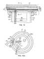
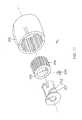
- FIG. 6Ais an end cross-sectional view of the distal end of the intermediate section of FIG. 6 , taken along line A--A.
- the distal end 26 of the ribbon 28is fixed to a distal end portion of the expander 22.
- an axial opening or slot 48Dis formed in the expander 22 near its distal end.
- the distal end 26 of the ribbonis inserted in the slot which is sized to fit the width of the ribbon but holds distal anchors 44D formed in the distal end of each strut 42A, 42B.
- the distal end of each strutis bent at an angle (e.g., about 90 degrees) to form a hook that latches to distal and proximal sides of the slot 48D in the expander 22.
Landscapes
- Health & Medical Sciences (AREA)
- Life Sciences & Earth Sciences (AREA)
- Medical Informatics (AREA)
- Molecular Biology (AREA)
- Cardiology (AREA)
- Biophysics (AREA)
- Pathology (AREA)
- Engineering & Computer Science (AREA)
- Biomedical Technology (AREA)
- Heart & Thoracic Surgery (AREA)
- Physiology (AREA)
- Physics & Mathematics (AREA)
- Surgery (AREA)
- Animal Behavior & Ethology (AREA)
- General Health & Medical Sciences (AREA)
- Public Health (AREA)
- Veterinary Medicine (AREA)
- Measurement And Recording Of Electrical Phenomena And Electrical Characteristics Of The Living Body (AREA)
- Media Introduction/Drainage Providing Device (AREA)
- Electrotherapy Devices (AREA)
- Surgical Instruments (AREA)
Abstract
Description
- The invention is directed to catheters for rapidly generating an electrical map of a chamber of a heart utilizing an assembly of contact electrodes for obtaining information indicative of chamber electrical activity, and optionally, of chamber geometry.
- Cardiac arrhythmias, the most common of which is ventricular tachycardia (VT), are a leading cause of death. In a majority of patients, VT originates from a 1 mm to 2 mm lesion located close to the inner surface of the heart chamber. One of the treatments for VT comprises mapping the electrical pathways of the heart to locate the lesion followed by ablation of the active site.
- Commonly assigned
U.S. Pat. No. 5,546,951 ;U.S. patent application Ser. No. 08/793,371 ; andPCT application WO 96/05768 U.S. patent applications Ser. Nos. 09/122,137 09/357,559 - Catheters containing position sensors may be used to determine the trajectory of points on the cardiac surface. These trajectories may be used to infer motion characteristics such as the contractility of the tissue. As disclosed in
U.S. Pat. No. 5,738,096 which is incorporated herein in its entirety by reference, maps depicting such motion characteristics may be constructed when the trajectory information is sampled at a sufficient number of points in the heart. - Electrical activity at a point in the heart is typically measured by advancing a catheter containing an electrical sensor at or near its distal tip to that point in the heart, contacting the tissue with the sensor and acquiring data at that point. One drawback with mapping a cardiac chamber using a catheter containing only a single, distal tip electrode is the long period of time required to accumulate data on a point-by-point basis over the requisite number of points required for a detailed map of the chamber as a whole. Accordingly, multiple-electrode catheters have been developed to simultaneously measure electrical activity at multiple points in the heart chamber.
U.S. Pat. No. 5,487,391 , directed to systems and methods for deriving and displaying the propagation velocities of electrical events in the heart, is illustrative of contact methods found in the art. In the system disclosed in the '391 patent, the electrical probe is a three-dimensional structure that takes the form of a basket. In the illustrated embodiment, the basket is composed of 8 spines, each of which carries eight electrodes, for a total of 64 electrodes in the probe. The basket structure is designed such that when deployed, its electrodes are held in intimate contact against the endocardial surface.U.S. Pat. No. 5,848,972 to Triedman et al. discloses a method for endocardial activation mapping using a multi-electrode catheter. In the method of the '972 patent, a multi-electrode catheter, preferably, a 50-electrode Webster-Jenkins.TM. basket catheter from Cordis-Webster of Baldwin Park, Calif., is advanced into a chamber of the heart. Anteroposterior (AP) and lateral fluorograms are obtained to establish the position and orientation of each of the electrodes. Electrograms are recorded from each of the electrodes in contact with the cardiac surface relative to a temporal reference such as the onset of the P-wave in sinus rhythm from a body surface ECG.U.S. Pat. No. 5,297,549 to Beatty et al. (the "Beatty method"), the disclosure of which is incorporated herein by reference, discloses a method and apparatus for mapping the electrical potential distribution of a heart chamber. In the Beatty method, an intra-cardiac multielectrode mapping catheter assembly is inserted into the heart. The mapping catheter assembly includes a multi-electrode assembly with an integral reference electrode, or, preferably, a companion reference catheter. In use, the electrodes are deployed in the form of a substantially spherical assembly. The electrode assembly is spatially referenced to a point on the endocardial surface by the reference electrode or by the reference catheter which is brought into contact with the endocardial surface. The preferred electrode assembly catheter is said to carry at least 24 individual electrode sites. Additionally, the Beatty method requires knowledge of the location of each of the electrode sites on the assembly, as well as a knowledge of the cardiac geometry. These locations are preferably determined by the method of impedance plethysmography.U.S. Pat. No. 5,311,866 to Kagan et al. discloses a heart mapping catheter assembly including an electrode assembly defining a number of electrode sites. The mapping catheter assembly also comprises a lumen to accept a reference catheter having a distal tip electrode assembly which may be used to probe the heart wall. In the preferred construction, the mapping catheter comprises a braid of insulated wires, preferably having 24 to 64 wires in the braid, each of which are used to form electrode sites. The catheter is said to be readily positionable in a heart to be used to acquire electrical activity information from a first set of non-contact electrode sites and/or a second set of in-contact electrode sites.U.S. Pat. Nos. 5,385,146 and5,450,846 to Goldreyer disclose a catheter that is said to be useful for mapping electrophysiological activity within the heart. The catheter body has a distal tip which is adapted for delivery of a stimulating pulse for pacing the heart or an ablative electrode for ablating tissue in contact with the tip. The catheter further comprises at least one pair of orthogonal electrodes to generate a difference signal indicative of the local cardiac electrical activity adjacent the orthogonal electrodes.U.S. Pat. No. 5,662,108 to Budd et al. discloses a process for measuring electrophysiologic data in a heart chamber. The method involves, in part, positioning a set of active and passive electrodes into the heart; supplying current to the active electrodes, thereby generating an electric field in the heart chamber; and measuring said electric field at said passive electrode sites. In one of the disclosed embodiments, the passive electrodes are contained in an assembly positioned on an inflatable balloon of a balloon catheter. In preferred embodiments, the assembly is said to have from 60 to 64 electrodes.- Recent common practice is to use a quadrapolar catheter to map the various chambers of the heart. Moreover, a catheter is dragged around the entire chamber until enough points can together be extrapolated to provide enough information.
- Thus, various methods have been proposed for increasing the speed of acquiring an electrical map of the heart. However, there remains a desire for a mapping catheter that reduces procedure time, by providing a distal electrode assembly that can expand and capture a heart chamber structure with a single sweeping moment. For example, with a slight rotation or translating motion, the assembly should be able to contact enough of the heart wall to be able to construct a complete map of the chamber. The assembly should be of a suitable shape, size and flexibility to avoid "tenting" of the heart tissue while being able to follow the motion of heart contractions.
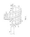
- The present invention is directed to a mapping catheter having a mapping electrode assembly that resembles a ribbon and is shaped in spiral form. The mapping electrode assembly has a support structure with shape memory and carries an array of electrodes fixed to an outer surface of the ribbon. When the mapping electrode assembly is expanded, multiple electrodes on the ribbon advantageously come into contact with tissue wall of a heart chamber, including an atrium or ventricle, for faster mapping by capturing the general chamber structure with a single sweeping movement. By providing a relatively large surface area in contact with tissue wall, the assembly provides numerous locations for recording in a mapping system. And, by slightly rotating and translating the mapping electrode assembly, a sufficient number of locations should be provided to contract a complete map of the chamber.
In one embodiment, the catheter has an elongated body and a mapping electrode assembly carried on an expander that extends the length of the catheter. The mapping electrode assembly comprises a band member configured in a spiral form around the expander such that the expander defines the longitudinal axis of the assembly. A distal end of the band member is fixed to the distal portion of the expander. A proximal end of the band member is fixed to the elongated body. As such, longitudinal movement of the expander relative to the elongated body causes the band member to change its spiral form between an expanded configuration and a contracted configuration. The band member has an outer surface on which are affixed a plurality of electrodes. The spiral form of the band member is supported by at least one strut with shape memory so the band member maintains its spiral form.
In a more detailed embodiment, the band member has an outer surface that faces outwardly along the spiral form and the electrodes are mounted on the outer surface to contact the tissue wall. The electrodes are provided along the length of the band member which spirals at least about 360 degrees about the expander, if not about 540 degrees. Lead wires extending from the electrodes pass through folded edges or "hems" of the band member and then through a central lumen of the expander toward the control handle.
In another detailed embodiment, the expander has an exposed proximal end adapted for direct manipulation by a user to expand and contract the mapping electrode assembly. The expander can be moved longitudinally or merely rotated to achieve expansion and contraction of the assembly. In another detailed embodiment, the catheter includes a control handle with a user interface assembly that controls a puller wire to expand and contract the mapping electrode. The puller wire extends through the central lumen of the expander and its distal end is anchored to a distal portion of the expander. The user interface assembly can be adapted for linear actuation or rotational actuation by a user. In the latter instance, the user interface assembly has components that convert rotational movement into longitudinal movement. - These and other features and advantages of the present invention will be better understood by reference to the following detailed description when considered in conjunction with the accompanying drawings. It is understood that selected structures and features have not been shown in certain drawings so as to provide better viewing of the remaining structures and features.
FIG. 1 is a perspective view of a catheter in accordance with an embodiment of the present invention.FIG. 2 is a perspective view of a mapping electrode assembly in a radially expanded or deployed configuration in accordance with an embodiment of the present invention.FIG. 3 is a perspective view of a mapping electrode assembly in a radially contracted configuration in accordance with an embodiment of the present invention.FIG. 4 is a schematic sectional view of a heart showing insertion of a catheter of the present invention into the left atrium, in accordance with an embodiment of the present invention.FIG. 5A is a side cross-sectional view of the catheter ofFIG. 1 , including a junction between a catheter body and an intermediate section, taken along one diameter.FIG. 5B is a side cross-sectional view of the catheter ofFIG. 1 , including a junction between a catheter body and an intermediate section, taken along another diameter.FIG. 6 is a side cross-sectional view of the catheter ofFIG. 1 , including a distal end of an intermediate section, taken along one diameter.FIG. 6A is an end cross-sectional view of the distal end of the intermediate section ofFIG. 6 , taken along line A--A.FIG. 6B is an end cross-sectional view of the distal end of the intermediate section and a proximal end of an outer sleeve ofFIG. 6 , taken along line B--B.FIG. 7 is a top plan view of a proximal end and a distal end of a band member of a mapping electrode assembly in accordance with an embodiment of the present invention.FIG. 8 is a top plan view of a mid-section a band member of a mapping electrode assembly in accordance with an embodiment of the present invention.FIG. 9 is a side cross-sectional view of a distal end of a band member affixed to an expander in accordance with an embodiment of the present invention.FIG. 9A is an end cross-sectional view of the distal end of the band member affixed to the expander ofFIG. 9 , taken along line A--A.FIG. 10 is a side cross-sectional view of the proximal end of the band member affixed to the expander in accordance with an embodiment of the present invention.FIG. 10A is an end cross-sectional view of the proximal end of the band member affixed to the expander ofFIG. 10 , taken along line A--A.FIG. 11 is a side cross-sectional view of a control handle in accordance with an embodiment of the present invention.FIG. 12 is a side cross-sectional view of a control handle in accordance with another embodiment of the present invention.FIG. 13 is a side cross-sectional view of the distal end of the band member affixed to the expander in accordance with another embodiment of the present invention.FIG. 13A is an end cross-sectional view of the proximal end of the band member affixed to the expander ofFIG. 13 , taken along line A--A.FIG. 14 is a top plan view of a catheter in accordance with another embodiment of the present invention.FIG. 15 is a perspective view of a control handle rotational interface assembly in accordance with one embodiment of the present invention.FIG. 16 is a perspective view of a control handle rotational interface assembly in accordance with another embodiment of the present invention.FIG. 17 is a perspective view of a control handle linear interface assembly in accordance with another embodiment of the present invention.- As illustrated in
FIGS. 1-4 the present invention includes a steerable catheter 10 with adistal tip section 17 that includes a distalmapping electrode assembly 19 carrying a plurality ofelectrodes 21 for multiple simultaneous contacts with wall tissue of a chamber, including aheart chamber 20, such as an atrium or ventricle. The assembly includes a flexible planar member or band resembling a "ribbon" 28 that is supported on anexpander 22 in a generally spiral configuration. Advantageously, the expander can be advanced and retracted relative to the catheter to vary the spiral configuration, including radially expanding (FIG. 2 ) and contracting the ribbon 28 (FIG. 3 ). The ribbon has aproximal end 24 and adistal end 26. Theproximal end 24 is fixed to anouter sleeve 27 through which theexpander 22 can move longitudinally, and thedistal end 26 is fixed to adistal end 25 of theexpander 22. As such, the spiral configuration of theribbon 28 is varied as theexpander 22 is advanced or retracted relative to the outer sleeve by an operator. Theassembly 19 may adopt the neutral or contracted configuration ofFIG. 2 while the catheter is moved through a patient's vasculature toward the target location and before it is deployed in the heart chamber. When theassembly 19 reaches the target location, it is deployed and manipulated into the expanded configuration ofFIGS. 3 and4 . - As shown in
FIGS. 5A and 5B , thecatheter body 12 comprises an elongated tubular construction having a single, axial orcentral lumen 18, but can optionally have multiple lumens if desired. Thecatheter body 12 is flexible, i.e., bendable, but substantially non-compressible along its length. Thecatheter body 12 can be of any suitable construction and made of any suitable material. A presently preferred construction comprises an outer wall made of polyurethane or PEBAX.RTM. (polyether block amide). The outer wall comprises an imbedded braided mesh of stainless steel or the like to increase torsional stiffness of thecatheter body 12 so that, when the control handle 16 is rotated, the distal end of the catheter body will rotate in a corresponding manner. - The outer diameter of the
catheter body 12 is not critical, but is preferably no more than about 8 french, more preferably 7 french. Likewise the thickness of the outer wall is not critical, but is preferably thin enough so that the central lumen can accommodate a puller wire, lead wires, sensor cables and any other wires, cables or tubes. If desired, the inner surface of the outer wall is lined with a stiffening tube (not shown) to provide improved torsional stability. An example of a catheter body construction suitable for use in connection with the present invention is described and depicted inU.S. Pat. No. 6,064,905 , the entire disclosure of which is incorporated herein by reference. - With further reference to
FIGS. 5A and 5B the deflectableintermediate section 14 comprises a short section oftubing 15 having multiple lumens, each occupied by the various components extending through the intermediate section. In the illustrated embodiment, there are fourlumens central lumen 32 arelead wires 29 for theelectrode assembly 19 and acable 36D for a distalelectromagnetic position sensor 38D. Passing through asecond lumen 33 is acable 36P for a proximalelectromagnetic position sensor 38P. For at least uni-directional deflection, afirst puller wire 40A passes through a third, off-axis lumen 34. For bi-directional deflection, asecond puller wire 40B passes through a fourth, off-axis lumen 35. - The
multi-lumened tubing 15 of theintermediate section 14 is made of a suitable nontoxic material that is preferably more flexible than thecatheter body 12. A suitable material is braided polyurethane or PEBAX, i.e., polyurethane or PEBAX with an embedded mesh of braided stainless steel or the like. The plurality and size of each lumen are not critical, provided there is sufficient room to house the components extending therethrough. Position of each lumen is also not critical, except the positions of thelumens puller wires lumens - The useful length of the catheter, i.e., that portion that can be inserted into the body can vary as desired. Preferably the useful length ranges from about 110 cm to about 120 cm. The length of the
intermediate section 14 is a relatively small portion of the useful length, and preferably ranges from about 3.5 cm to about 10 cm, more preferably from about 5 cm to about 6.5 cm. - A preferred means for attaching the
catheter body 12 to theintermediate section 14 is illustrated inFIGS. 5A and 5B . The proximal end of theintermediate section 14 comprises an inner circumferential notch that receives the outer surface of the distal end of the stiffeningtube 31 of thecatheter body 12. Theintermediate section 14 andcatheter body 12 are attached by glue or the like, for example, polyurethane. If desired, a spacer (not shown) can be provided within thecatheter body 12 between the distal end of the stiffeningtube 31 and the proximal end of theintermediate section 14 to provide a transition in flexibility at the junction of thecatheter body 12 and the intermediate section, which allows the junction to bend smoothly without folding or kinking. An example of such a spacer is described in more detail inU.S. Patent No. 5,964,757 , the disclosure of which is incorporated herein by reference. - As illustrated in
FIGS. 6 and 6A , adeflection puller wire 40A extends through thecentral lumen 18 of thecatheter body 12 and into thethird lumen 34 of theintermediate section 14. Anotherdeflection puller wire 40B extends through thecentral lumen 18 and into thefourth lumen 35 of theintermediate section 14. The distal ends of the deflection puller wires are anchored to the wall of thetubing 15 near the distal end of theintermediate section 14 by means of T-anchors 81. In theintermediate section 14, each deflection puller wire extends through a plastic, e.g., Teflon.RTM.,sheath 83, which prevents the deflection puller wires from cutting into the wall of thetubing 15 of theintermediate section 14 when theintermediate section 14 is deflected. - As shown in
FIG. 5A , compression coils 47 in surrounding relation to the deflection puller wires extend from the proximal end of thecatheter body 12 to about the proximal end of theintermediate section 14. The compression coils 47 are made of any suitable metal, e.g., stainless steel. The compression coils are tightly wound on itself to provide flexibility, i.e., bending, but to resist compression. The inner diameter of the compression coils is preferably slightly larger than the diameter of the puller wires. A Teflon.RTM. coating on the puller wires allows them to slide freely within the compression coils. The outer surface of the compression coils is covered by a flexible,non-conductive sheath 49 to prevent contact between the compression coils and other components, such as lead wires and cables, etc. A non-conductive sheath can be made of polyimide tubing. - The compression coils are anchored at their proximal ends to the proximal end of the stiffening
tube 20 in thecatheter body 12 by glue joint (not shown) and at its distal end near the proximal end of theintermediate section 14 in thelumen FIG. 5A ). - As for the
distal tip section 17, the spiral-shapedribbon electrode assembly 19 is mounted to the distal end of theintermediate section 14. As shown inFIG. 6 , theribbon 28 extends around theexpander 22 between about 180 and 720 degrees, preferably at least 360 degrees, and more preferably about 540 degrees. The ribbon has anouter surface 39 that consistently faces outwardly from theexpander 22. Elongated and resembling a tubular shaft or rod, the expander forms the central longitudinal axis of theelectrode assembly 19. - The
ribbon 28 may be constructed of any suitable material, including PEBAX. The exposed length of the ribbon between its distal and proximal ends is about 10 and 25 cm, and preferably about 15 mm, and more preferably about 20 mm. The ribbon has a width about 2 and 10 mm, and preferably about 5 and 8 mm. It is understood that the ribbon may be constructed as a solid member, a woven member or a web member, provided the structure is sufficiently rigid yet flexible to support the electrodes and hold the generally spiral form in the expanded and contracted configurations. - Supporting the
ribbon 28 on theexpander 22 and enabling the ribbon to elastically and flexibly maintain its shape are two shape-memory struts lengthwise edge 43 of the ribbon and is secured and protected by a peripheral length edge portion of the ribbon (or "hem") 45 that is folded alongedge 43. Extending widthwise between the folded edge portions are a plurality ofelongated electrodes 21, ranging between about 10 and 50, and more preferably about 20 and 41. In the illustrated embodiment, they are evenly spaced, span nearly the length of the ribbon and are generally parallel with the expander and longitudinal axis of the catheter. They are affixed to the outer surface in a suitable manner, including, e.g., adhesives, so that they can readily contact tissue when the assembly is expanded (seeFIG. 4 ). - Each
electrode 21 is connected to arespective lead wire 29. In the illustrated embodiment ofFIGS. 7 and8 , leadwires 29D for a distal portion of theelectrodes 21D travel alongside onelengthwise edge 43 of theribbon 28 andlead wires 29P for a proximal portion of theelectrodes 21P travel alongside the otherlengthwise edge 43 of the ribbon. The lead wires are also covered and protected by thehem 45 of the ribbon inward of the nitinol struts 42A, 42B. - The
distal end 26 of theribbon 28 is fixed to a distal end portion of theexpander 22. As illustrated inFIGS. 9, 9A , an axial opening orslot 48D is formed in theexpander 22 near its distal end. Thedistal end 26 of the ribbon is inserted in the slot which is sized to fit the width of the ribbon but holds distal anchors 44D formed in the distal end of eachstrut slot 48D in theexpander 22. The distal widthwiseedge portion 50 of ribbon is tucked in theslot 48D and the anchors 44D are positioned inlumen 23 of theexpander 22.Lead wires 29D for the distal portion of theelectrodes 21D (only one shown for clarity) extend into thelumen 23 of theexpander 22 where they pass proximally toward the control handle 16. The distal end of the ribbon 26 (along with the distal strut anchors 44D) is fixed and sealed in theslot 48D with suitable material, e.g., epoxy. - Housed in the distal end of the
expander 22 is thedistal location sensor 38D. In the illustrated embodiment, the distal location sensor is distal of thedistal end 26 of theribbon 28 however it can be at another location as appropriate.Cable 36D for thedistal location sensor 38D also passes through thelumen 23 of theexpander 22 toward the control handle 16. Adistal tip 51 of theexpander 22 is sealed with suitable material, e.g., epoxy to form an atraumatic end. - The
proximal end 24 of theribbon 28 is fixed to theouter sleeve 29 near its distal end. As illustrated inFIGS. 6 ,10 and 10A , an opening axial slot 48Pis formed in theouter sleeve 27. Theproximal end 24 of theribbon 28 is inserted in theslot 48P which is sized to fit the width of the ribbon but holdsanchors 44P formed in the proximal end of each strut 44A, 44B. In the illustrated embodiment, the proximal end of each strut is bent at an angle (e.g., about 90 degrees) to form a hook that latches to distal and proximal sides of the slot in theouter sleeve 27. The proximal widthwiseedge portion 50P of ribbon is tucked in theslot 48P and theanchors 44P are positioned in agap 52 between theexpander 22 and theouter sleeve 27.Lead wires 29P for the proximal portion of theelectrodes 21P extend into thelumen 23 of theexpander 22 where they pass proximally toward the control handle 16 (along with thelead wires 29D for the distal portion of theelectrodes 21D and thecable 36D for thedistal location sensor 38D). Theproximal end 24 of the ribbon (along with the proximal strut anchors 44P) is fixed and sealed in theslot 48P with suitable material, e.g., epoxy. - Housed in the distal end of
tubing 15 of theintermediate deflection section 14 is theproximal location sensor 38P. In the illustrated embodiment ofFIG. 6A , theproximal location sensor 38P is proximal of the proximal end of theouter sleeve 27 however it can be at another location as appropriate.Cable 36P for theproximal location sensor 38P also passes through thelumen 23 of theexpander 22 toward the control handle 16. - The coordinates of the
distal sensor 38D, relative to those of theproximal sensor 38P, are determined and taken together with other known information pertaining to the curvature/position of theribbon 28 of theelectrode assembly 19. This information is used to find the positions of theelectrodes 21 mounted on the ribbon. However, it is understood that other location sensors may be used, including Single-Axis-Sensors (SAS), such as those described inU.S. Application No. 12/982,765, filed December 30, 2010 - As shown in the depicted embodiment, the
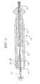
expander 22 is generally coaxial with theintermediate deflection section 14 and thecatheter body 12. As shown inFIG. 11 , theexpander 22 has aproximal end 53 attached to the control handle 16, as described further below, so that the expander can be moved longitudinally relative to thecatheter body 12 to thereby expand and contract theelectrode assembly 19. Theexpander 22 comprises a material sufficiently rigid to achieve this function. In a preferred embodiment, theexpander 22 comprises braided polyimide tubing, i.e., tubing having inner and outer layers of polyimide with a braided stainless steel mesh therebetween, as is generally known in the art. - Longitudinal movement of the
expander 22 relative to thecatheter body 12, which results in expansion of theelectrode assembly 18, is accomplished by manipulation of the control handle 16. As shown inFIG. 11 , the control handle 16 comprises a generally-hollow handle housing 54 and a piston (or thumb control) 56 slidably mounted within the distal end of the handle housing. The proximal end of thecatheter body 12 is fixedly attached to the distal end of thepiston 56 by a shrink sleeve (not shown), as is generally known in the art, or by any other suitable method. Within the control handle 16, the proximal end of theexpander 22 extends through apassage 57 in thepiston 56 and is secured and fixed to thehandle housing 54. Theexpander 22 is fixedly attached to thehandle housing 54 by any suitable method, preferably with polyurethane glue or the like. - In one embodiment, the
piston 56 is approximately about 2 inches long, and the support tube 58 andexpander 22 are attached to thehandle housing 54 at a position about 0.5 inch distal to the proximal end of the handle and about 1 inch proximal to the proximal end of the piston in the neutral position. The piston is in the neutral position (with the distal and proximal ends of the ribbon at a maximum separation) when theelectrode assembly 19 is more tightly coiled around the expander, i.e., not expanded. And by moving thepiston 56 distally, thecatheter body 12 and consequently theintermediate section 14 andouter sleeve 27 and theproximal end 24 of theribbon 28 is moved distally (decreasing the separation between the proximal and distal ends 24, 26 of the ribbon) to radially expand the ribbon (FIG. 2 ). Astopper 60 can be provided on theexpander 22 to limit the minimum separation permitted between theends outer sleeve 27. Thelead wires sensor cables lumen 23 of theexpander 22 and past theproximal end 53 of the expander where they are attached to suitable connector(s) 62 at the proximal end of the handle housing. - In an alternate embodiment of
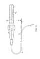
FIG. 12 , theexpander 22 passes through the control handle 16 and has an exposed proximal end 53' proximal of the control handle 16. In this instance, the expander can be made of a material with sufficient torsional stiffness such that when the exposed proximal end 53' is rotated by a user, thedistal end 25 of the expander rotates in a corresponding manner. As such, a user can radially expand the ribbon and contract it by merely rotating the exposed proximal end of the expander. - In another alternate embodiment as illustrated in
FIGS. 13 and 13A , longitudinal movement of the expander can be accomplished by athird puller wire 80 extending through thelumen 23 of theexpander 22. The distal end of the puller wire is anchored in any suitable manner, for example, a T-bar 82, at or near the distal end of the expander. Manipulation of the third puller wire 80 (and any other puller wires such aspuller wires 12/550,204, filed August 28, 2009 12/550,307, filed August 28, 2009 FIG. 14 , acontrol handle 16A has adeflection control knob 75 and arotational assembly 90. Thedeflection control knob 75 allows control of deflection ofintermediate section 14 and therotational assembly 90 allows control of the expansion and contraction of theelectrode assembly 19. In the illustrated embodiment ofFIG. 15 , therotational assembly 90 includes an outerrotational member 202, aninner gear 204 with a guidingslot 242 and acylindrical member 207 having atrack 232 in which afollower 240 rides as guided by theslot 242. Rotation of themember 202 rotates thegear 204 which in turn slides thefollower 240 along the track by means of theslot 242. As the follower sides in the track, the puller wire attached thereto is moved longitudinally relative to the control handle to actuate a component, including expansion and contraction of the electrode assembly.FIG. 16 illustrates another embodiment of a rotational assembly 90' operating in a similar manner, except with a gearless inner member 204' is rotationally coupled to the outer rotational member 202' bypins 250 received inapertures 252. FIG. 17 illustrates yet another embodiment of a suitable rotational assembly. Alinear interface 302 rotates an inner cylindrical member by apin 303. The control handle housing has an axial slot (not shown) that guides movement of theinterface 302 along the longitudinal axis of the control handle. As thepin 303 moves longitudinally, it slides intrack 305 and rotates an outercylindrical member 304 which has anaxial guiding slot 342 in which sits afollower 340 that slides along atrack 332 formed in an inner cylindrical member. As the follower moves in the track, the puller wire attached thereto moves longitudinally relative to the control handle to actuate a component, including the electrode assembly for expansion and contraction.- Each
location sensor corresponding sensor cable U.S. Pat. No. 6,024,739 , the disclosure of which is incorporated herein by reference. Each sensor cable comprises multiple wires encased within a plastic covered sheath. In the sensor control module, the wires of the sensor cable are connected to the circuit board. The circuit board amplifies the signal received from the corresponding location sensor and transmits it to a computer in a form understandable by the computer by means of the sensor connector at the proximal end of the sensor control module. Also, because the catheter is designed for single use only, the circuit board preferably contains an EPROM chip that shuts down the circuit board approximately twenty-four hours after the catheter has been used. This prevents the catheter, or at least the location sensor, from being used twice. - To use the catheter of the invention, an electrophysiologist introduces a guiding sheath, into the patient, as is generally known in the art. A suitable guiding sheath for use in connection with the inventive catheter is the PREFACE.TM. Braided Guiding Sheath (commercially available from Biosense Webster, Inc., Diamond Bar, Calif.). The catheter is introduced through the guiding sheath. The guiding sheath covers the
electrode assembly 19 internally in a collapsed or contracted position so that the entire catheter can be passed down a vein or artery to a desired location. Once the distal end of the catheter reaches the desired location, the guiding sheath is withdrawn. Theexpander 22 is then manipulated so that theribbon 28 of theelectrode assembly 18 flexes outwardly into an expanded arrangement (FIG. 4 ). In such an arrangement, theelectrodes 21 on the ribbon contact the tissue of the heart. As will be recognized by one skilled in the art, theelectrode assembly 19 can be fully or partially expanded in a variety of configurations depending on the configuration of the region of the heart being mapped. - The catheter of the present invention increases the speed of acquiring an electrical map of the heart by providing an electrode assembly that can expand and capture a heart chamber structure with a single sweeping moment. For example, with a slight rotation or translating motion, the assembly should be able to contact enough of the heart wall to be able to construct a complete map of the chamber. The assembly should be of a suitable shape, size and flexibility to avoid "tenting" of the heart tissue while being able to follow the motion of heart contractions.
- Using the electrodes on the ribbon of the
electrode assembly 18 in combination with the distal endproximal location sensors catheter body 12, or one or more reference electrodes can be placed outside the body of the patient. By using the inventive catheter with themultiple electrodes 21 on theelectrode assembly 19, the electrophysiologist can obtain a true anatomy of the heart by measuring multiple points simultaneously, allowing him to map the heart more quickly. - The preceding description has been presented with reference to presently preferred embodiments of the invention. Workers skilled in the art and technology to which this invention pertains will appreciate that alterations and changes in the described structure may be practiced without meaningfully departing from the principal, spirit and scope of this invention. Any feature or structure disclosed in one embodiment may be incorporated in lieu of or in addition to other features of any other embodiments, as needed or appropriate. As understood by one of ordinary skill in the art, the drawings are not necessarily to scale, and for purposes of clarity, the plurality of lead wires illustrated are not intended to necessarily represent the plurality of electrodes employed in the catheter. Accordingly, the foregoing description should not be read as pertaining only to the precise structures described and illustrated in the accompanying drawings, but rather should be read consistent with and as support to the following claims which are to have their fullest and fair scope.
Claims (14)
- A catheter, comprising:an elongated body;an elongated expander extending through the elongated body, anda distal electrode assembly distal a distal end of the elongated body, including:a band member configured in a spiral form about the expander, the band member having a length between a distal end and a proximal end, the distal end being fixed to the expander, the proximal end being in a fixed relationship with the elongated body;a plurality of electrodes carried on the band member; andat least one support member with shape memory extending along the length of the band member to flexibly support the spiral form;wherein the expander is longitudinally movable relative to the elongated body to vary the spiral form of the band member.
- A catheter of claim 1, wherein the expander is longitudinally movable relative to the elongated body to vary the spiral form of the band member between a radially expanded configuration and a radially contracted configuration.
- A catheter of claim 1, wherein the expander has an exposed proximal end adapted direct manipulation by a user for longitudinal movement relative to the elongated body.
- A catheter of claim 1, further comprising:a control handle with a user interface assembly, anda puller wire extending through the elongated body and having a distal end anchored in the expander and a proximal end responsive to the user interface assembly for longitudinal movement relative to the elongated body.
- A catheter, comprising:a catheter body;a deflectable intermediate section distal of the catheter body;an elongated expander extending through the catheter body and the intermediate section, anda distal electrode assembly distal a distal end of the intermediate section, including:a band member configured in a spiral form about the expander, the band member having a length between a distal end and a proximal end, the distal end being fixed to the expander, the proximal end being fixed at or near a distal end of the intermediate section;a plurality of electrodes carried on the band member; andat least one support member with shape memory extending along the length of the band member to flexibly support the spiral form;wherein the expander is longitudinally movable relative to the elongated body to vary the spiral form of the band member between a radially expanded configuration and a radially contracted configuration.
- A catheter of claim 1 or claim 5, wherein the band member has an outer surface that faces outwardly along the spiral form and the electrodes are mounted on the outer surface.
- A catheter of claim 1 or claim 5, further comprising a second support member, wherein each support member extends along a respective lengthwise edge of the band member.
- A catheter of claim 5, wherein the expander is longitudinally movable relative to the elongated body to vary a separation distance between the proximal and distal ends of the band member.
- A catheter of claim 1 or claim 5, wherein the electrodes are elongated and generally parallel to the expander.
- A catheter of claim 5, wherein the expander is adapted for longitudinal movement relative to the elongated body by direct manipulation by a user of a proximal end of the expander.
- A catheter of claim 5, further comprising:a control handle with a user interface assembly, anda puller wire extending through the elongated body and having a distal end anchored in the expander and a proximal end responsive to the user interface assembly for longitudinal movement relative to the catheter body and the intermediate section.
- A catheter of claim 4 or claim 11, wherein the user interface assembly includes an interface configured for linear motion relative to a control handle housing.
- A catheter of claim 4 or claim 11, wherein the user interface assembly includes an interface configured for rotational movement relative to a control handle housing.
- A catheter of claim 5, further comprising a distal position sensor housed at or near a distal end of the expander, and a proximal position sensor positioned proximal of the distal position sensor.
Priority Applications (2)
| Application Number | Priority Date | Filing Date | Title |
|---|---|---|---|
| DK13169910.0TDK2653098T3 (en) | 2011-10-04 | 2012-10-03 | Mapping catheter with coil electrode units |
| EP13169910.0AEP2653098B1 (en) | 2011-10-04 | 2012-10-03 | Mapping catheter with spiral electrode assembly |
Applications Claiming Priority (1)
| Application Number | Priority Date | Filing Date | Title |
|---|---|---|---|
| US13/252,891US8498686B2 (en) | 2011-10-04 | 2011-10-04 | Mapping catheter with spiral electrode assembly |
Related Child Applications (2)
| Application Number | Title | Priority Date | Filing Date |
|---|---|---|---|
| EP13169910.0ADivisionEP2653098B1 (en) | 2011-10-04 | 2012-10-03 | Mapping catheter with spiral electrode assembly |
| EP13169910.0ADivision-IntoEP2653098B1 (en) | 2011-10-04 | 2012-10-03 | Mapping catheter with spiral electrode assembly |
Publications (2)
| Publication Number | Publication Date |
|---|---|
| EP2578146A1true EP2578146A1 (en) | 2013-04-10 |
| EP2578146B1 EP2578146B1 (en) | 2016-08-31 |
Family
ID=46968074
Family Applications (2)
| Application Number | Title | Priority Date | Filing Date |
|---|---|---|---|
| EP13169910.0ANot-in-forceEP2653098B1 (en) | 2011-10-04 | 2012-10-03 | Mapping catheter with spiral electrode assembly |
| EP12187072.9ANot-in-forceEP2578146B1 (en) | 2011-10-04 | 2012-10-03 | Mapping catheter with electrode assembly in form of a spiral ribbon |
Family Applications Before (1)
| Application Number | Title | Priority Date | Filing Date |
|---|---|---|---|
| EP13169910.0ANot-in-forceEP2653098B1 (en) | 2011-10-04 | 2012-10-03 | Mapping catheter with spiral electrode assembly |
Country Status (8)
| Country | Link |
|---|---|
| US (1) | US8498686B2 (en) |
| EP (2) | EP2653098B1 (en) |
| JP (1) | JP6109517B2 (en) |
| CN (1) | CN103027677B (en) |
| AU (1) | AU2012227335B2 (en) |
| CA (1) | CA2791588A1 (en) |
| DK (1) | DK2653098T3 (en) |
| ES (1) | ES2531078T3 (en) |
Families Citing this family (64)
| Publication number | Priority date | Publication date | Assignee | Title |
|---|---|---|---|---|
| US6702811B2 (en) | 1999-04-05 | 2004-03-09 | Medtronic, Inc. | Ablation catheter assembly with radially decreasing helix and method of use |
| US7653438B2 (en) | 2002-04-08 | 2010-01-26 | Ardian, Inc. | Methods and apparatus for renal neuromodulation |
| US20140018880A1 (en) | 2002-04-08 | 2014-01-16 | Medtronic Ardian Luxembourg S.A.R.L. | Methods for monopolar renal neuromodulation |
| KR101912960B1 (en) | 2010-10-25 | 2018-10-29 | 메드트로닉 아르디언 룩셈부르크 에스에이알엘 | Catheter Appratuses having Multi-Electrode Arrays for Renal Neuromodulation and Associated Systems and Methods |
| CN107374723B (en) | 2012-05-11 | 2020-08-28 | 美敦力Af卢森堡有限责任公司 | Catheter apparatus |
| US9095321B2 (en) | 2012-11-21 | 2015-08-04 | Medtronic Ardian Luxembourg S.A.R.L. | Cryotherapeutic devices having integral multi-helical balloons and methods of making the same |
| US9179974B2 (en) | 2013-03-15 | 2015-11-10 | Medtronic Ardian Luxembourg S.A.R.L. | Helical push wire electrode |
| US20150073515A1 (en) | 2013-09-09 | 2015-03-12 | Medtronic Ardian Luxembourg S.a.r.I. | Neuromodulation Catheter Devices and Systems Having Energy Delivering Thermocouple Assemblies and Associated Methods |
| US9795315B2 (en) | 2014-01-28 | 2017-10-24 | John Bullinga | Catheter system for mapping of the left atrium, right atrium and coronary sinus |
| CN106232043B (en) | 2014-04-24 | 2019-07-23 | 美敦力阿迪安卢森堡有限公司 | Nerve modulation conduit and relevant system and method with braiding axle |
| US9820664B2 (en) | 2014-11-20 | 2017-11-21 | Biosense Webster (Israel) Ltd. | Catheter with high density electrode spine array |
| WO2016183337A2 (en) | 2015-05-12 | 2016-11-17 | National University Of Ireland Galway | Devices for therapeutic nasal neuromodulation and associated methods and systems |
| US9949656B2 (en) | 2015-06-29 | 2018-04-24 | Biosense Webster (Israel) Ltd. | Catheter with stacked spine electrode assembly |
| US10537259B2 (en)* | 2015-06-29 | 2020-01-21 | Biosense Webster (Israel) Ltd. | Catheter having closed loop array with in-plane linear electrode portion |
| US10575742B2 (en) | 2015-06-30 | 2020-03-03 | Biosense Webster (Israel) Ltd. | Catheter having closed electrode assembly with spines of uniform length |
| US10905329B2 (en) | 2016-06-09 | 2021-02-02 | Biosense Webster (Israel) Ltd. | Multi-function conducting elements for a catheter |
| US10912475B2 (en)* | 2016-08-24 | 2021-02-09 | Biosense Webster (Israel) Ltd | Catheter with split electrode sleeve and related methods |
| US11400205B2 (en) | 2016-11-23 | 2022-08-02 | Biosense Webster (Israel) Ltd. | Balloon-in-balloon irrigation balloon catheter |
| US20180161093A1 (en)* | 2016-12-08 | 2018-06-14 | Biosense Webster (Israel) Ltd. | Irrigated balloon catheter with support spines and variable shape |
| EP3554406A1 (en)* | 2016-12-19 | 2019-10-23 | Boston Scientific Scimed Inc. | Distally-facing electrode array with longitudinally mounted splines |
| US12029545B2 (en) | 2017-05-30 | 2024-07-09 | Biosense Webster (Israel) Ltd. | Catheter splines as location sensors |
| US10765475B2 (en)* | 2017-10-31 | 2020-09-08 | Biosense Webster (Israel) Ltd. | All-in-one spiral catheter |
| US20190175263A1 (en)* | 2017-12-12 | 2019-06-13 | Biosense Webster (Israel) Ltd. | Balloon catheter with reverse spiral guidewire |
| KR101981683B1 (en)* | 2018-01-18 | 2019-05-23 | 최인상 | Electrosurgical device |
| US20190314083A1 (en) | 2018-04-11 | 2019-10-17 | Biosense Webster (Israel) Ltd. | Flexible Multi-Arm Catheter with Diametrically Opposed Sensing Electrodes |
| US12102781B2 (en) | 2018-06-29 | 2024-10-01 | Biosense Webster (Israel) Ltd. | Reinforcement for irrigated electrophysiology balloon catheter with flexible-circuit electrodes |
| US11071585B2 (en) | 2018-09-14 | 2021-07-27 | Biosense Webster (Israel) Ltd. | Systems and methods of ablating cardiac tissue |
| US11045628B2 (en) | 2018-12-11 | 2021-06-29 | Biosense Webster (Israel) Ltd. | Balloon catheter with high articulation |
| US11207016B2 (en) | 2018-12-28 | 2021-12-28 | Biosense Webster (Israel) Ltd. | Mapping ECG signals using a multipole electrode assembly |
| US11850051B2 (en) | 2019-04-30 | 2023-12-26 | Biosense Webster (Israel) Ltd. | Mapping grid with high density electrode array |
| US11712172B2 (en) | 2019-07-18 | 2023-08-01 | Biosense Webster (Israel) Ltd. | Visual guidance for positioning a distal end of a medical probe |
| US12369975B2 (en) | 2019-09-12 | 2025-07-29 | Biosense Webster (Israel) Ltd. | Balloon catheter with force sensor |
| US20210077184A1 (en)* | 2019-09-16 | 2021-03-18 | Biosense Webster (Israel) Ltd. | Catheter with thin-film electrodes on expandable membrane |
| US11633228B2 (en) | 2019-10-04 | 2023-04-25 | Biosense Webster (Israel) Ltd. | Identifying pulmonary vein occlusion by dimension deformations of balloon catheter |
| US12369974B2 (en) | 2019-10-10 | 2025-07-29 | Biosense Webster (Israel) Ltd. | Touch indication of balloon-catheter ablation electrode via balloon surface temperature measurement |
| US11564614B2 (en) | 2019-10-30 | 2023-01-31 | St. Jude Medical, Cardiology Division, Inc. | Systems and methods for identifying ablation locations using electrical parameter data |
| US12137967B2 (en) | 2019-11-12 | 2024-11-12 | Biosense Webster (Israel) Ltd. | Accurate positioning and shape visualization of balloon catheter ablation tags |
| US11950930B2 (en) | 2019-12-12 | 2024-04-09 | Biosense Webster (Israel) Ltd. | Multi-dimensional acquisition of bipolar signals from a catheter |
| US11517218B2 (en) | 2019-12-20 | 2022-12-06 | Biosense Webster (Israel) Ltd. | Selective graphical presentation of electrophysiological parameters |
| US12097339B2 (en)* | 2019-12-31 | 2024-09-24 | Biosense Webster (Israel) Ltd. | System and methods of using a catheter with an anchoring mechanism |
| US12232874B2 (en) | 2020-05-29 | 2025-02-25 | Biosense Webster (Israel) Ltd. | Electrode apparatus for diagnosis of arrhythmias |
| US11987017B2 (en) | 2020-06-08 | 2024-05-21 | Biosense Webster (Israel) Ltd. | Features to assist in assembly and testing of devices |
| WO2022038546A1 (en)* | 2020-08-18 | 2022-02-24 | St. Jude Medical, Cardiology Division, Inc. | High-density electrode catheters with magnetic position tracking |
| US12048479B2 (en) | 2020-09-10 | 2024-07-30 | Biosense Webster (Israel) Ltd. | Surface mounted electrode catheter |
| US11950840B2 (en) | 2020-09-22 | 2024-04-09 | Biosense Webster (Israel) Ltd. | Basket catheter having insulated ablation electrodes |
| US11950841B2 (en) | 2020-09-22 | 2024-04-09 | Biosense Webster (Israel) Ltd. | Basket catheter having insulated ablation electrodes and diagnostic electrodes |
| US12082875B2 (en) | 2020-09-24 | 2024-09-10 | Biosense Webster (Israel) Ltd | Balloon catheter having a coil for sensing tissue temperature and position of the balloon |
| CN112263320A (en)* | 2020-09-29 | 2021-01-26 | 杭州睿笛生物科技有限公司 | Cervical ablation device |
| KR20230082639A (en)* | 2020-10-07 | 2023-06-08 | 아비오메드 유럽 게엠베하 | Patch electrode assemblies for conductivity and admittance measurements |
| US12239364B2 (en) | 2020-10-07 | 2025-03-04 | Biosense Webster (Israel) Ltd. | Printed proximal electrodes of an expandable catheter for use as a common electrode |
| US11974803B2 (en) | 2020-10-12 | 2024-05-07 | Biosense Webster (Israel) Ltd. | Basket catheter with balloon |
| US12201786B2 (en) | 2020-12-17 | 2025-01-21 | Biosense Webster (Israel) Ltd. | Measurement of distal end dimension of catheters using magnetic fields |
| US11918383B2 (en) | 2020-12-21 | 2024-03-05 | Biosense Webster (Israel) Ltd. | Visualizing performance of catheter electrodes |
| US11957852B2 (en) | 2021-01-14 | 2024-04-16 | Biosense Webster (Israel) Ltd. | Intravascular balloon with slidable central irrigation tube |
| US11849995B2 (en) | 2021-02-18 | 2023-12-26 | Biosense Webster (Israel) Ltd. | Detection of balloon catheter tissue contact using optical measurement |
| US12064170B2 (en) | 2021-05-13 | 2024-08-20 | Biosense Webster (Israel) Ltd. | Distal assembly for catheter with lumens running along spines |
| US12364426B2 (en) | 2021-08-12 | 2025-07-22 | Biosense Webster (Israel) Ltd. | Electro-anatomical mapping and annotation presented in electrophysiological procedures |
| US12114905B2 (en) | 2021-08-27 | 2024-10-15 | Biosense Webster (Israel) Ltd. | Reinforcement and stress relief for an irrigated electrophysiology balloon catheter with flexible-circuit electrodes |
| US12004804B2 (en) | 2021-09-09 | 2024-06-11 | Biosense Webster (Israel) Ltd. | Basket catheter with mushroom shape distal tip |
| US12011280B2 (en) | 2021-10-04 | 2024-06-18 | Biosense Webster (Israel) Ltd. | Electrophysiological mapping in the presence of injury current |
| US12419683B2 (en) | 2021-12-22 | 2025-09-23 | Biosense Webster (Israel) Ltd. | Irreversible electroporation with shorted electrodes |
| CN115568919B (en)* | 2022-11-24 | 2025-01-17 | 上海安钛克医疗科技有限公司 | Ultrasound guiding catheter and ultrasound guiding puncture system |
| CN116035586B (en)* | 2023-03-31 | 2023-06-27 | 中国医学科学院阜外医院 | Mapping Catheter |
| CN117159130B (en)* | 2023-09-22 | 2024-09-06 | 朗信医疗科技(无锡)有限公司 | Natural cavity ablation electrode |
Citations (17)
| Publication number | Priority date | Publication date | Assignee | Title |
|---|---|---|---|---|
| US5297549A (en) | 1992-09-23 | 1994-03-29 | Endocardial Therapeutics, Inc. | Endocardial mapping system |
| US5311866A (en) | 1992-09-23 | 1994-05-17 | Endocardial Therapeutics, Inc. | Heart mapping catheter |
| US5385146A (en) | 1993-01-08 | 1995-01-31 | Goldreyer; Bruce N. | Orthogonal sensing for use in clinical electrophysiology |
| US5487391A (en) | 1994-01-28 | 1996-01-30 | Ep Technologies, Inc. | Systems and methods for deriving and displaying the propagation velocities of electrical events in the heart |
| WO1996005768A1 (en) | 1994-08-19 | 1996-02-29 | Biosense, Inc. | Medical diagnosis, treatment and imaging systems |
| US5546951A (en) | 1993-07-20 | 1996-08-20 | Biosense, Inc. | Method and apparatus for studying cardiac arrhythmias |
| WO1997017892A1 (en)* | 1995-11-13 | 1997-05-22 | Cardiac Pathways Corporation | Endocardial mapping and/or ablation catheter probe and method |
| US5662108A (en) | 1992-09-23 | 1997-09-02 | Endocardial Solutions, Inc. | Electrophysiology mapping system |
| US5738096A (en) | 1993-07-20 | 1998-04-14 | Biosense, Inc. | Cardiac electromechanics |
| US5848972A (en) | 1995-09-15 | 1998-12-15 | Children's Medical Center Corporation | Method for endocardial activation mapping using a multi-electrode catheter |
| US5964757A (en) | 1997-09-05 | 1999-10-12 | Cordis Webster, Inc. | Steerable direct myocardial revascularization catheter |
| US6024739A (en) | 1997-09-05 | 2000-02-15 | Cordis Webster, Inc. | Method for detecting and revascularizing ischemic myocardial tissue |
| US6064905A (en) | 1998-06-18 | 2000-05-16 | Cordis Webster, Inc. | Multi-element tip electrode mapping catheter |
| WO2003089997A2 (en)* | 2002-03-15 | 2003-10-30 | C.R. Bard, Inc. | Method and apparatus for control of ablation energy and electrogram acquisition through multiple common electrodes in an electrophysiology catheter |
| US20050222563A1 (en)* | 2004-03-31 | 2005-10-06 | Mcdaniel Benjamin D | Catheter for circumferential ablation at or near a pulmonary vein |
| EP2269505A1 (en)* | 2009-07-02 | 2011-01-05 | St. Jude Medical, Atrial Fibrillation Division, Inc. | Apparatus and methods for contactless electrophysiology studies |
| US20110054287A1 (en)* | 2009-08-28 | 2011-03-03 | Jefferey William Schultz | Catheter with multi-functional control handle having rotational mechanism |
Family Cites Families (24)
| Publication number | Priority date | Publication date | Assignee | Title |
|---|---|---|---|---|
| US5156151A (en) | 1991-02-15 | 1992-10-20 | Cardiac Pathways Corporation | Endocardial mapping and ablation system and catheter probe |
| US5156551A (en)* | 1991-10-01 | 1992-10-20 | Reliance Comm/Tec Corporation | Front-facing line terminal block assembly |
| US5239999A (en)* | 1992-03-27 | 1993-08-31 | Cardiac Pathways Corporation | Helical endocardial catheter probe |
| US5772590A (en)* | 1992-06-30 | 1998-06-30 | Cordis Webster, Inc. | Cardiovascular catheter with laterally stable basket-shaped electrode array with puller wire |
| US5309910A (en) | 1992-09-25 | 1994-05-10 | Ep Technologies, Inc. | Cardiac mapping and ablation systems |
| AU680569B2 (en) | 1993-11-10 | 1997-07-31 | Cardiorhythm | Electrode array catheter |
| US5730127A (en) | 1993-12-03 | 1998-03-24 | Avitall; Boaz | Mapping and ablation catheter system |
| US5680860A (en) | 1994-07-07 | 1997-10-28 | Cardiac Pathways Corporation | Mapping and/or ablation catheter with coilable distal extremity and method for using same |
| US6690963B2 (en) | 1995-01-24 | 2004-02-10 | Biosense, Inc. | System for determining the location and orientation of an invasive medical instrument |
| US6322559B1 (en)* | 1998-07-06 | 2001-11-27 | Vnus Medical Technologies, Inc. | Electrode catheter having coil structure |
| US6301496B1 (en) | 1998-07-24 | 2001-10-09 | Biosense, Inc. | Vector mapping of three-dimensionally reconstructed intrabody organs and method of display |
| US6226542B1 (en) | 1998-07-24 | 2001-05-01 | Biosense, Inc. | Three-dimensional reconstruction of intrabody organs |
| US6241665B1 (en) | 1998-10-21 | 2001-06-05 | Plc Medical System, Inc. | Percutaneous mapping system |
| AU7720100A (en)* | 1999-09-27 | 2001-04-30 | Essex Technology, Inc. | Rotate-to-advance catheterization system |
| US6628976B1 (en)* | 2000-01-27 | 2003-09-30 | Biosense Webster, Inc. | Catheter having mapping assembly |
| US7255695B2 (en) | 2001-04-27 | 2007-08-14 | C.R. Bard, Inc. | Systems and methods for three-dimensional mapping of electrical activity |
| US6748255B2 (en)* | 2001-12-14 | 2004-06-08 | Biosense Webster, Inc. | Basket catheter with multiple location sensors |
| US20050033136A1 (en)* | 2003-08-01 | 2005-02-10 | Assaf Govari | Catheter with electrode strip |
| CN1913935B (en)* | 2004-01-26 | 2010-05-12 | 导管治疗有限公司 | Catheter assembly with adjustable ring |
| EP2759276A1 (en)* | 2005-06-20 | 2014-07-30 | Medtronic Ablation Frontiers LLC | Ablation catheter |
| US7907994B2 (en)* | 2007-01-11 | 2011-03-15 | Biosense Webster, Inc. | Automated pace-mapping for identification of cardiac arrhythmic conductive pathways and foci |
| JP4027411B1 (en)* | 2007-03-29 | 2007-12-26 | 日本ライフライン株式会社 | Electrode catheter |
| US8747351B2 (en) | 2009-08-28 | 2014-06-10 | Biosense Webster, Inc. | Catheter with multi-functional control handle having linear mechanism |
| EP2667812A1 (en)* | 2011-01-28 | 2013-12-04 | Medtronic Ardian Luxembourg S.à.r.l. | Ablation catheter equipped with a shape memory material |
- 2011
- 2011-10-04USUS13/252,891patent/US8498686B2/ennot_activeExpired - Fee Related
- 2012
- 2012-09-26AUAU2012227335Apatent/AU2012227335B2/ennot_activeCeased
- 2012-09-28CNCN201210370788.6Apatent/CN103027677B/ennot_activeExpired - Fee Related
- 2012-10-02CACA2791588Apatent/CA2791588A1/ennot_activeAbandoned
- 2012-10-03EPEP13169910.0Apatent/EP2653098B1/ennot_activeNot-in-force
- 2012-10-03DKDK13169910.0Tpatent/DK2653098T3/enactive
- 2012-10-03ESES13169910Tpatent/ES2531078T3/enactiveActive
- 2012-10-03JPJP2012221035Apatent/JP6109517B2/ennot_activeExpired - Fee Related
- 2012-10-03EPEP12187072.9Apatent/EP2578146B1/ennot_activeNot-in-force
Patent Citations (18)
| Publication number | Priority date | Publication date | Assignee | Title |
|---|---|---|---|---|
| US5662108A (en) | 1992-09-23 | 1997-09-02 | Endocardial Solutions, Inc. | Electrophysiology mapping system |
| US5311866A (en) | 1992-09-23 | 1994-05-17 | Endocardial Therapeutics, Inc. | Heart mapping catheter |
| US5297549A (en) | 1992-09-23 | 1994-03-29 | Endocardial Therapeutics, Inc. | Endocardial mapping system |
| US5385146A (en) | 1993-01-08 | 1995-01-31 | Goldreyer; Bruce N. | Orthogonal sensing for use in clinical electrophysiology |
| US5450846A (en) | 1993-01-08 | 1995-09-19 | Goldreyer; Bruce N. | Method for spatially specific electrophysiological sensing for mapping, pacing and ablating human myocardium and a catheter for the same |
| US5738096A (en) | 1993-07-20 | 1998-04-14 | Biosense, Inc. | Cardiac electromechanics |
| US5546951A (en) | 1993-07-20 | 1996-08-20 | Biosense, Inc. | Method and apparatus for studying cardiac arrhythmias |
| US5487391A (en) | 1994-01-28 | 1996-01-30 | Ep Technologies, Inc. | Systems and methods for deriving and displaying the propagation velocities of electrical events in the heart |
| WO1996005768A1 (en) | 1994-08-19 | 1996-02-29 | Biosense, Inc. | Medical diagnosis, treatment and imaging systems |
| US5848972A (en) | 1995-09-15 | 1998-12-15 | Children's Medical Center Corporation | Method for endocardial activation mapping using a multi-electrode catheter |
| WO1997017892A1 (en)* | 1995-11-13 | 1997-05-22 | Cardiac Pathways Corporation | Endocardial mapping and/or ablation catheter probe and method |
| US5964757A (en) | 1997-09-05 | 1999-10-12 | Cordis Webster, Inc. | Steerable direct myocardial revascularization catheter |
| US6024739A (en) | 1997-09-05 | 2000-02-15 | Cordis Webster, Inc. | Method for detecting and revascularizing ischemic myocardial tissue |
| US6064905A (en) | 1998-06-18 | 2000-05-16 | Cordis Webster, Inc. | Multi-element tip electrode mapping catheter |
| WO2003089997A2 (en)* | 2002-03-15 | 2003-10-30 | C.R. Bard, Inc. | Method and apparatus for control of ablation energy and electrogram acquisition through multiple common electrodes in an electrophysiology catheter |
| US20050222563A1 (en)* | 2004-03-31 | 2005-10-06 | Mcdaniel Benjamin D | Catheter for circumferential ablation at or near a pulmonary vein |
| EP2269505A1 (en)* | 2009-07-02 | 2011-01-05 | St. Jude Medical, Atrial Fibrillation Division, Inc. | Apparatus and methods for contactless electrophysiology studies |
| US20110054287A1 (en)* | 2009-08-28 | 2011-03-03 | Jefferey William Schultz | Catheter with multi-functional control handle having rotational mechanism |
Also Published As
| Publication number | Publication date |
|---|---|
| ES2531078T3 (en) | 2015-03-10 |
| JP2013078587A (en) | 2013-05-02 |
| EP2653098B1 (en) | 2014-12-10 |
| US8498686B2 (en) | 2013-07-30 |
| JP6109517B2 (en) | 2017-04-05 |
| CA2791588A1 (en) | 2013-04-04 |
| AU2012227335A1 (en) | 2013-04-18 |
| EP2653098A1 (en) | 2013-10-23 |
| EP2578146B1 (en) | 2016-08-31 |
| CN103027677A (en) | 2013-04-10 |
| CN103027677B (en) | 2016-09-28 |
| US20130085360A1 (en) | 2013-04-04 |
| DK2653098T3 (en) | 2015-01-12 |
| AU2012227335B2 (en) | 2015-06-11 |
Similar Documents
| Publication | Publication Date | Title |
|---|---|---|
| AU2012227335B2 (en) | Mapping catheter with spiral electrode assembly | |
| JP7032501B2 (en) | Basket catheter with distal tip of microelectrode array | |
| US11992321B2 (en) | Basket catheter with deflectable spine | |
| EP1415680B1 (en) | Multi-tip steerable catheter | |
| JP4795358B2 (en) | Internal reference coronary sinus catheter | |
| EP3345563A1 (en) | Multi-electrode assembly with controlled folding mechanism | |
| EP3053517A1 (en) | Basket catheter with far-field electrode | |
| CN105796090A (en) | Basket catheter with improved spine flexibility |
Legal Events
| Date | Code | Title | Description |
|---|---|---|---|
| PUAI | Public reference made under article 153(3) epc to a published international application that has entered the european phase | Free format text:ORIGINAL CODE: 0009012 | |
| AK | Designated contracting states | Kind code of ref document:A1 Designated state(s):AL AT BE BG CH CY CZ DE DK EE ES FI FR GB GR HR HU IE IS IT LI LT LU LV MC MK MT NL NO PL PT RO RS SE SI SK SM TR | |
| AX | Request for extension of the european patent | Extension state:BA ME | |
| 17P | Request for examination filed | Effective date:20130517 | |
| 17Q | First examination report despatched | Effective date:20130920 | |
| GRAP | Despatch of communication of intention to grant a patent | Free format text:ORIGINAL CODE: EPIDOSNIGR1 | |
| INTG | Intention to grant announced | Effective date:20160308 | |
| RAP1 | Party data changed (applicant data changed or rights of an application transferred) | Owner name:BIOSENSE WEBSTER (ISRAEL), LTD. | |
| GRAJ | Information related to disapproval of communication of intention to grant by the applicant or resumption of examination proceedings by the epo deleted | Free format text:ORIGINAL CODE: EPIDOSDIGR1 | |
| GRAR | Information related to intention to grant a patent recorded | Free format text:ORIGINAL CODE: EPIDOSNIGR71 | |
| GRAS | Grant fee paid | Free format text:ORIGINAL CODE: EPIDOSNIGR3 | |
| GRAA | (expected) grant | Free format text:ORIGINAL CODE: 0009210 | |
| RAP1 | Party data changed (applicant data changed or rights of an application transferred) | Owner name:BIOSENSE WEBSTER (ISRAEL) LTD. | |
| INTG | Intention to grant announced | Effective date:20160721 | |
| AK | Designated contracting states | Kind code of ref document:B1 Designated state(s):AL AT BE BG CH CY CZ DE DK EE ES FI FR GB GR HR HU IE IS IT LI LT LU LV MC MK MT NL NO PL PT RO RS SE SI SK SM TR | |
| REG | Reference to a national code | Ref country code:CH Ref legal event code:EP Ref country code:GB Ref legal event code:FG4D | |
| RAP2 | Party data changed (patent owner data changed or rights of a patent transferred) | Owner name:BIOSENSE WEBSTER (ISRAEL) LTD. | |
| REG | Reference to a national code | Ref country code:FR Ref legal event code:PLFP Year of fee payment:5 | |
| REG | Reference to a national code | Ref country code:IE Ref legal event code:FG4D | |
| REG | Reference to a national code | Ref country code:DE Ref legal event code:R096 Ref document number:602012022341 Country of ref document:DE | |
| REG | Reference to a national code | Ref country code:AT Ref legal event code:REF Ref document number:824222 Country of ref document:AT Kind code of ref document:T Effective date:20161015 | |
| REG | Reference to a national code | Ref country code:NL Ref legal event code:FP | |
| REG | Reference to a national code | Ref country code:LT Ref legal event code:MG4D | |
| REG | Reference to a national code | Ref country code:AT Ref legal event code:MK05 Ref document number:824222 Country of ref document:AT Kind code of ref document:T Effective date:20160831 | |
| PG25 | Lapsed in a contracting state [announced via postgrant information from national office to epo] | Ref country code:HR Free format text:LAPSE BECAUSE OF FAILURE TO SUBMIT A TRANSLATION OF THE DESCRIPTION OR TO PAY THE FEE WITHIN THE PRESCRIBED TIME-LIMIT Effective date:20160831 Ref country code:FI Free format text:LAPSE BECAUSE OF FAILURE TO SUBMIT A TRANSLATION OF THE DESCRIPTION OR TO PAY THE FEE WITHIN THE PRESCRIBED TIME-LIMIT Effective date:20160831 Ref country code:RS Free format text:LAPSE BECAUSE OF FAILURE TO SUBMIT A TRANSLATION OF THE DESCRIPTION OR TO PAY THE FEE WITHIN THE PRESCRIBED TIME-LIMIT Effective date:20160831 Ref country code:NO Free format text:LAPSE BECAUSE OF FAILURE TO SUBMIT A TRANSLATION OF THE DESCRIPTION OR TO PAY THE FEE WITHIN THE PRESCRIBED TIME-LIMIT Effective date:20161130 Ref country code:LT Free format text:LAPSE BECAUSE OF FAILURE TO SUBMIT A TRANSLATION OF THE DESCRIPTION OR TO PAY THE FEE WITHIN THE PRESCRIBED TIME-LIMIT Effective date:20160831 | |
| PG25 | Lapsed in a contracting state [announced via postgrant information from national office to epo] | Ref country code:ES Free format text:LAPSE BECAUSE OF FAILURE TO SUBMIT A TRANSLATION OF THE DESCRIPTION OR TO PAY THE FEE WITHIN THE PRESCRIBED TIME-LIMIT Effective date:20160831 Ref country code:LV Free format text:LAPSE BECAUSE OF FAILURE TO SUBMIT A TRANSLATION OF THE DESCRIPTION OR TO PAY THE FEE WITHIN THE PRESCRIBED TIME-LIMIT Effective date:20160831 Ref country code:GR Free format text:LAPSE BECAUSE OF FAILURE TO SUBMIT A TRANSLATION OF THE DESCRIPTION OR TO PAY THE FEE WITHIN THE PRESCRIBED TIME-LIMIT Effective date:20161201 Ref country code:SE Free format text:LAPSE BECAUSE OF FAILURE TO SUBMIT A TRANSLATION OF THE DESCRIPTION OR TO PAY THE FEE WITHIN THE PRESCRIBED TIME-LIMIT Effective date:20160831 Ref country code:AT Free format text:LAPSE BECAUSE OF FAILURE TO SUBMIT A TRANSLATION OF THE DESCRIPTION OR TO PAY THE FEE WITHIN THE PRESCRIBED TIME-LIMIT Effective date:20160831 | |
| PG25 | Lapsed in a contracting state [announced via postgrant information from national office to epo] | Ref country code:EE Free format text:LAPSE BECAUSE OF FAILURE TO SUBMIT A TRANSLATION OF THE DESCRIPTION OR TO PAY THE FEE WITHIN THE PRESCRIBED TIME-LIMIT Effective date:20160831 Ref country code:RO Free format text:LAPSE BECAUSE OF FAILURE TO SUBMIT A TRANSLATION OF THE DESCRIPTION OR TO PAY THE FEE WITHIN THE PRESCRIBED TIME-LIMIT Effective date:20160831 | |
| PG25 | Lapsed in a contracting state [announced via postgrant information from national office to epo] | Ref country code:SM Free format text:LAPSE BECAUSE OF FAILURE TO SUBMIT A TRANSLATION OF THE DESCRIPTION OR TO PAY THE FEE WITHIN THE PRESCRIBED TIME-LIMIT Effective date:20160831 Ref country code:PT Free format text:LAPSE BECAUSE OF FAILURE TO SUBMIT A TRANSLATION OF THE DESCRIPTION OR TO PAY THE FEE WITHIN THE PRESCRIBED TIME-LIMIT Effective date:20170102 Ref country code:DK Free format text:LAPSE BECAUSE OF FAILURE TO SUBMIT A TRANSLATION OF THE DESCRIPTION OR TO PAY THE FEE WITHIN THE PRESCRIBED TIME-LIMIT Effective date:20160831 Ref country code:CZ Free format text:LAPSE BECAUSE OF FAILURE TO SUBMIT A TRANSLATION OF THE DESCRIPTION OR TO PAY THE FEE WITHIN THE PRESCRIBED TIME-LIMIT Effective date:20160831 Ref country code:SK Free format text:LAPSE BECAUSE OF FAILURE TO SUBMIT A TRANSLATION OF THE DESCRIPTION OR TO PAY THE FEE WITHIN THE PRESCRIBED TIME-LIMIT Effective date:20160831 Ref country code:BG Free format text:LAPSE BECAUSE OF FAILURE TO SUBMIT A TRANSLATION OF THE DESCRIPTION OR TO PAY THE FEE WITHIN THE PRESCRIBED TIME-LIMIT Effective date:20161130 Ref country code:PL Free format text:LAPSE BECAUSE OF FAILURE TO SUBMIT A TRANSLATION OF THE DESCRIPTION OR TO PAY THE FEE WITHIN THE PRESCRIBED TIME-LIMIT Effective date:20160831 | |
| REG | Reference to a national code | Ref country code:CH Ref legal event code:PL | |
| REG | Reference to a national code | Ref country code:DE Ref legal event code:R097 Ref document number:602012022341 Country of ref document:DE | |
| PLBE | No opposition filed within time limit | Free format text:ORIGINAL CODE: 0009261 | |
| STAA | Information on the status of an ep patent application or granted ep patent | Free format text:STATUS: NO OPPOSITION FILED WITHIN TIME LIMIT | |
| REG | Reference to a national code | Ref country code:IE Ref legal event code:MM4A | |
| PG25 | Lapsed in a contracting state [announced via postgrant information from national office to epo] | Ref country code:CH Free format text:LAPSE BECAUSE OF NON-PAYMENT OF DUE FEES Effective date:20161031 Ref country code:LI Free format text:LAPSE BECAUSE OF NON-PAYMENT OF DUE FEES Effective date:20161031 | |
| 26N | No opposition filed | Effective date:20170601 | |
| PG25 | Lapsed in a contracting state [announced via postgrant information from national office to epo] | Ref country code:LU Free format text:LAPSE BECAUSE OF NON-PAYMENT OF DUE FEES Effective date:20161003 Ref country code:SI Free format text:LAPSE BECAUSE OF FAILURE TO SUBMIT A TRANSLATION OF THE DESCRIPTION OR TO PAY THE FEE WITHIN THE PRESCRIBED TIME-LIMIT Effective date:20160831 | |
| REG | Reference to a national code | Ref country code:FR Ref legal event code:PLFP Year of fee payment:6 | |
| PG25 | Lapsed in a contracting state [announced via postgrant information from national office to epo] | Ref country code:IE Free format text:LAPSE BECAUSE OF NON-PAYMENT OF DUE FEES Effective date:20161003 | |
| PG25 | Lapsed in a contracting state [announced via postgrant information from national office to epo] | Ref country code:CY Free format text:LAPSE BECAUSE OF FAILURE TO SUBMIT A TRANSLATION OF THE DESCRIPTION OR TO PAY THE FEE WITHIN THE PRESCRIBED TIME-LIMIT Effective date:20160831 Ref country code:HU Free format text:LAPSE BECAUSE OF FAILURE TO SUBMIT A TRANSLATION OF THE DESCRIPTION OR TO PAY THE FEE WITHIN THE PRESCRIBED TIME-LIMIT; INVALID AB INITIO Effective date:20121003 | |
| PG25 | Lapsed in a contracting state [announced via postgrant information from national office to epo] | Ref country code:MT Free format text:LAPSE BECAUSE OF NON-PAYMENT OF DUE FEES Effective date:20161031 Ref country code:TR Free format text:LAPSE BECAUSE OF FAILURE TO SUBMIT A TRANSLATION OF THE DESCRIPTION OR TO PAY THE FEE WITHIN THE PRESCRIBED TIME-LIMIT Effective date:20160831 Ref country code:MC Free format text:LAPSE BECAUSE OF FAILURE TO SUBMIT A TRANSLATION OF THE DESCRIPTION OR TO PAY THE FEE WITHIN THE PRESCRIBED TIME-LIMIT Effective date:20160831 Ref country code:IS Free format text:LAPSE BECAUSE OF FAILURE TO SUBMIT A TRANSLATION OF THE DESCRIPTION OR TO PAY THE FEE WITHIN THE PRESCRIBED TIME-LIMIT Effective date:20160831 Ref country code:MK Free format text:LAPSE BECAUSE OF FAILURE TO SUBMIT A TRANSLATION OF THE DESCRIPTION OR TO PAY THE FEE WITHIN THE PRESCRIBED TIME-LIMIT Effective date:20160831 | |
| REG | Reference to a national code | Ref country code:FR Ref legal event code:PLFP Year of fee payment:7 | |
| PG25 | Lapsed in a contracting state [announced via postgrant information from national office to epo] | Ref country code:AL Free format text:LAPSE BECAUSE OF FAILURE TO SUBMIT A TRANSLATION OF THE DESCRIPTION OR TO PAY THE FEE WITHIN THE PRESCRIBED TIME-LIMIT Effective date:20160831 | |
| PGFP | Annual fee paid to national office [announced via postgrant information from national office to epo] | Ref country code:SK Payment date:20180712 Year of fee payment:11 | |
| PGFP | Annual fee paid to national office [announced via postgrant information from national office to epo] | Ref country code:DE Payment date:20180918 Year of fee payment:7 | |
| PGFP | Annual fee paid to national office [announced via postgrant information from national office to epo] | Ref country code:GB Payment date:20181003 Year of fee payment:7 Ref country code:IT Payment date:20181018 Year of fee payment:7 | |
| PGFP | Annual fee paid to national office [announced via postgrant information from national office to epo] | Ref country code:FR Payment date:20190913 Year of fee payment:8 Ref country code:NL Payment date:20190912 Year of fee payment:8 | |
| REG | Reference to a national code | Ref country code:DE Ref legal event code:R119 Ref document number:602012022341 Country of ref document:DE | |
| PG25 | Lapsed in a contracting state [announced via postgrant information from national office to epo] | Ref country code:DE Free format text:LAPSE BECAUSE OF NON-PAYMENT OF DUE FEES Effective date:20200501 | |
| REG | Reference to a national code | Ref country code:BE Ref legal event code:MM Effective date:20191031 | |
| PG25 | Lapsed in a contracting state [announced via postgrant information from national office to epo] | Ref country code:BE Free format text:LAPSE BECAUSE OF NON-PAYMENT OF DUE FEES Effective date:20191031 | |
| GBPC | Gb: european patent ceased through non-payment of renewal fee | Effective date:20191003 | |
| PG25 | Lapsed in a contracting state [announced via postgrant information from national office to epo] | Ref country code:IT Free format text:LAPSE BECAUSE OF NON-PAYMENT OF DUE FEES Effective date:20191003 Ref country code:GB Free format text:LAPSE BECAUSE OF NON-PAYMENT OF DUE FEES Effective date:20191003 | |
| REG | Reference to a national code | Ref country code:NL Ref legal event code:MM Effective date:20201101 | |
| PG25 | Lapsed in a contracting state [announced via postgrant information from national office to epo] | Ref country code:NL Free format text:LAPSE BECAUSE OF NON-PAYMENT OF DUE FEES Effective date:20201101 Ref country code:FR Free format text:LAPSE BECAUSE OF NON-PAYMENT OF DUE FEES Effective date:20201031 |