EP2578144A1 - Multipurpose host system for invasive cardiovascular diagnostic measurement acquisition and display - Google Patents
Multipurpose host system for invasive cardiovascular diagnostic measurement acquisition and displayDownload PDFInfo
- Publication number
- EP2578144A1 EP2578144A1EP12172646.7AEP12172646AEP2578144A1EP 2578144 A1EP2578144 A1EP 2578144A1EP 12172646 AEP12172646 AEP 12172646AEP 2578144 A1EP2578144 A1EP 2578144A1
- Authority
- EP
- European Patent Office
- Prior art keywords
- intravascular
- pressure
- display
- parameter
- user interface
- Prior art date
- Legal status (The legal status is an assumption and is not a legal conclusion. Google has not performed a legal analysis and makes no representation as to the accuracy of the status listed.)
- Granted
Links
Images


Classifications
- A—HUMAN NECESSITIES
- A61—MEDICAL OR VETERINARY SCIENCE; HYGIENE
- A61B—DIAGNOSIS; SURGERY; IDENTIFICATION
- A61B5/00—Measuring for diagnostic purposes; Identification of persons
- A61B5/02—Detecting, measuring or recording for evaluating the cardiovascular system, e.g. pulse, heart rate, blood pressure or blood flow
- A61B5/026—Measuring blood flow
- A61B5/0265—Measuring blood flow using electromagnetic means, e.g. electromagnetic flowmeter
- A61B5/027—Measuring blood flow using electromagnetic means, e.g. electromagnetic flowmeter using catheters
- A—HUMAN NECESSITIES
- A61—MEDICAL OR VETERINARY SCIENCE; HYGIENE
- A61B—DIAGNOSIS; SURGERY; IDENTIFICATION
- A61B5/00—Measuring for diagnostic purposes; Identification of persons
- A61B5/0033—Features or image-related aspects of imaging apparatus, e.g. for MRI, optical tomography or impedance tomography apparatus; Arrangements of imaging apparatus in a room
- A61B5/0035—Features or image-related aspects of imaging apparatus, e.g. for MRI, optical tomography or impedance tomography apparatus; Arrangements of imaging apparatus in a room adapted for acquisition of images from more than one imaging mode, e.g. combining MRI and optical tomography
- A—HUMAN NECESSITIES
- A61—MEDICAL OR VETERINARY SCIENCE; HYGIENE
- A61B—DIAGNOSIS; SURGERY; IDENTIFICATION
- A61B5/00—Measuring for diagnostic purposes; Identification of persons
- A61B5/0059—Measuring for diagnostic purposes; Identification of persons using light, e.g. diagnosis by transillumination, diascopy, fluorescence
- A61B5/0062—Arrangements for scanning
- A61B5/0066—Optical coherence imaging
- A—HUMAN NECESSITIES
- A61—MEDICAL OR VETERINARY SCIENCE; HYGIENE
- A61B—DIAGNOSIS; SURGERY; IDENTIFICATION
- A61B5/00—Measuring for diagnostic purposes; Identification of persons
- A61B5/0059—Measuring for diagnostic purposes; Identification of persons using light, e.g. diagnosis by transillumination, diascopy, fluorescence
- A61B5/0082—Measuring for diagnostic purposes; Identification of persons using light, e.g. diagnosis by transillumination, diascopy, fluorescence adapted for particular medical purposes
- A61B5/0084—Measuring for diagnostic purposes; Identification of persons using light, e.g. diagnosis by transillumination, diascopy, fluorescence adapted for particular medical purposes for introduction into the body, e.g. by catheters
- A—HUMAN NECESSITIES
- A61—MEDICAL OR VETERINARY SCIENCE; HYGIENE
- A61B—DIAGNOSIS; SURGERY; IDENTIFICATION
- A61B5/00—Measuring for diagnostic purposes; Identification of persons
- A61B5/01—Measuring temperature of body parts ; Diagnostic temperature sensing, e.g. for malignant or inflamed tissue
- A—HUMAN NECESSITIES
- A61—MEDICAL OR VETERINARY SCIENCE; HYGIENE
- A61B—DIAGNOSIS; SURGERY; IDENTIFICATION
- A61B5/00—Measuring for diagnostic purposes; Identification of persons
- A61B5/02—Detecting, measuring or recording for evaluating the cardiovascular system, e.g. pulse, heart rate, blood pressure or blood flow
- A61B5/0205—Simultaneously evaluating both cardiovascular conditions and different types of body conditions, e.g. heart and respiratory condition
- A61B5/02055—Simultaneously evaluating both cardiovascular condition and temperature
- A—HUMAN NECESSITIES
- A61—MEDICAL OR VETERINARY SCIENCE; HYGIENE
- A61B—DIAGNOSIS; SURGERY; IDENTIFICATION
- A61B5/00—Measuring for diagnostic purposes; Identification of persons
- A61B5/02—Detecting, measuring or recording for evaluating the cardiovascular system, e.g. pulse, heart rate, blood pressure or blood flow
- A61B5/021—Measuring pressure in heart or blood vessels
- A61B5/0215—Measuring pressure in heart or blood vessels by means inserted into the body
- A—HUMAN NECESSITIES
- A61—MEDICAL OR VETERINARY SCIENCE; HYGIENE
- A61B—DIAGNOSIS; SURGERY; IDENTIFICATION
- A61B5/00—Measuring for diagnostic purposes; Identification of persons
- A61B5/02—Detecting, measuring or recording for evaluating the cardiovascular system, e.g. pulse, heart rate, blood pressure or blood flow
- A61B5/026—Measuring blood flow
- A—HUMAN NECESSITIES
- A61—MEDICAL OR VETERINARY SCIENCE; HYGIENE
- A61B—DIAGNOSIS; SURGERY; IDENTIFICATION
- A61B5/00—Measuring for diagnostic purposes; Identification of persons
- A61B5/145—Measuring characteristics of blood in vivo, e.g. gas concentration or pH-value ; Measuring characteristics of body fluids or tissues, e.g. interstitial fluid or cerebral tissue
- A61B5/14539—Measuring characteristics of blood in vivo, e.g. gas concentration or pH-value ; Measuring characteristics of body fluids or tissues, e.g. interstitial fluid or cerebral tissue for measuring pH
- A—HUMAN NECESSITIES
- A61—MEDICAL OR VETERINARY SCIENCE; HYGIENE
- A61B—DIAGNOSIS; SURGERY; IDENTIFICATION
- A61B5/00—Measuring for diagnostic purposes; Identification of persons
- A61B5/145—Measuring characteristics of blood in vivo, e.g. gas concentration or pH-value ; Measuring characteristics of body fluids or tissues, e.g. interstitial fluid or cerebral tissue
- A61B5/1468—Measuring characteristics of blood in vivo, e.g. gas concentration or pH-value ; Measuring characteristics of body fluids or tissues, e.g. interstitial fluid or cerebral tissue using chemical or electrochemical methods, e.g. by polarographic means
- A61B5/1473—Measuring characteristics of blood in vivo, e.g. gas concentration or pH-value ; Measuring characteristics of body fluids or tissues, e.g. interstitial fluid or cerebral tissue using chemical or electrochemical methods, e.g. by polarographic means invasive, e.g. introduced into the body by a catheter
- A—HUMAN NECESSITIES
- A61—MEDICAL OR VETERINARY SCIENCE; HYGIENE
- A61B—DIAGNOSIS; SURGERY; IDENTIFICATION
- A61B5/00—Measuring for diagnostic purposes; Identification of persons
- A61B5/68—Arrangements of detecting, measuring or recording means, e.g. sensors, in relation to patient
- A61B5/6846—Arrangements of detecting, measuring or recording means, e.g. sensors, in relation to patient specially adapted to be brought in contact with an internal body part, i.e. invasive
- A61B5/6847—Arrangements of detecting, measuring or recording means, e.g. sensors, in relation to patient specially adapted to be brought in contact with an internal body part, i.e. invasive mounted on an invasive device
- A61B5/6851—Guide wires
- A—HUMAN NECESSITIES
- A61—MEDICAL OR VETERINARY SCIENCE; HYGIENE
- A61B—DIAGNOSIS; SURGERY; IDENTIFICATION
- A61B5/00—Measuring for diagnostic purposes; Identification of persons
- A61B5/68—Arrangements of detecting, measuring or recording means, e.g. sensors, in relation to patient
- A61B5/6846—Arrangements of detecting, measuring or recording means, e.g. sensors, in relation to patient specially adapted to be brought in contact with an internal body part, i.e. invasive
- A61B5/6847—Arrangements of detecting, measuring or recording means, e.g. sensors, in relation to patient specially adapted to be brought in contact with an internal body part, i.e. invasive mounted on an invasive device
- A61B5/6852—Catheters
- A—HUMAN NECESSITIES
- A61—MEDICAL OR VETERINARY SCIENCE; HYGIENE
- A61B—DIAGNOSIS; SURGERY; IDENTIFICATION
- A61B5/00—Measuring for diagnostic purposes; Identification of persons
- A61B5/72—Signal processing specially adapted for physiological signals or for diagnostic purposes
- A—HUMAN NECESSITIES
- A61—MEDICAL OR VETERINARY SCIENCE; HYGIENE
- A61B—DIAGNOSIS; SURGERY; IDENTIFICATION
- A61B5/00—Measuring for diagnostic purposes; Identification of persons
- A61B5/74—Details of notification to user or communication with user or patient; User input means
- A61B5/742—Details of notification to user or communication with user or patient; User input means using visual displays
- A61B5/743—Displaying an image simultaneously with additional graphical information, e.g. symbols, charts, function plots
- A—HUMAN NECESSITIES
- A61—MEDICAL OR VETERINARY SCIENCE; HYGIENE
- A61B—DIAGNOSIS; SURGERY; IDENTIFICATION
- A61B5/00—Measuring for diagnostic purposes; Identification of persons
- A61B5/74—Details of notification to user or communication with user or patient; User input means
- A61B5/742—Details of notification to user or communication with user or patient; User input means using visual displays
- A61B5/7435—Displaying user selection data, e.g. icons in a graphical user interface
- A—HUMAN NECESSITIES
- A61—MEDICAL OR VETERINARY SCIENCE; HYGIENE
- A61B—DIAGNOSIS; SURGERY; IDENTIFICATION
- A61B5/00—Measuring for diagnostic purposes; Identification of persons
- A61B5/74—Details of notification to user or communication with user or patient; User input means
- A61B5/7475—User input or interface means, e.g. keyboard, pointing device, joystick
- A—HUMAN NECESSITIES
- A61—MEDICAL OR VETERINARY SCIENCE; HYGIENE
- A61B—DIAGNOSIS; SURGERY; IDENTIFICATION
- A61B8/00—Diagnosis using ultrasonic, sonic or infrasonic waves
- A61B8/06—Measuring blood flow
- A—HUMAN NECESSITIES
- A61—MEDICAL OR VETERINARY SCIENCE; HYGIENE
- A61B—DIAGNOSIS; SURGERY; IDENTIFICATION
- A61B8/00—Diagnosis using ultrasonic, sonic or infrasonic waves
- A61B8/12—Diagnosis using ultrasonic, sonic or infrasonic waves in body cavities or body tracts, e.g. by using catheters
- A—HUMAN NECESSITIES
- A61—MEDICAL OR VETERINARY SCIENCE; HYGIENE
- A61B—DIAGNOSIS; SURGERY; IDENTIFICATION
- A61B8/00—Diagnosis using ultrasonic, sonic or infrasonic waves
- A61B8/46—Ultrasonic, sonic or infrasonic diagnostic devices with special arrangements for interfacing with the operator or the patient
- A61B8/467—Ultrasonic, sonic or infrasonic diagnostic devices with special arrangements for interfacing with the operator or the patient characterised by special input means
- A61B8/468—Ultrasonic, sonic or infrasonic diagnostic devices with special arrangements for interfacing with the operator or the patient characterised by special input means allowing annotation or message recording
- A—HUMAN NECESSITIES
- A61—MEDICAL OR VETERINARY SCIENCE; HYGIENE
- A61B—DIAGNOSIS; SURGERY; IDENTIFICATION
- A61B8/00—Diagnosis using ultrasonic, sonic or infrasonic waves
- A61B8/48—Diagnostic techniques
- A61B8/488—Diagnostic techniques involving Doppler signals
- G—PHYSICS
- G16—INFORMATION AND COMMUNICATION TECHNOLOGY [ICT] SPECIALLY ADAPTED FOR SPECIFIC APPLICATION FIELDS
- G16H—HEALTHCARE INFORMATICS, i.e. INFORMATION AND COMMUNICATION TECHNOLOGY [ICT] SPECIALLY ADAPTED FOR THE HANDLING OR PROCESSING OF MEDICAL OR HEALTHCARE DATA
- G16H30/00—ICT specially adapted for the handling or processing of medical images
- G16H30/40—ICT specially adapted for the handling or processing of medical images for processing medical images, e.g. editing
- A—HUMAN NECESSITIES
- A61—MEDICAL OR VETERINARY SCIENCE; HYGIENE
- A61B—DIAGNOSIS; SURGERY; IDENTIFICATION
- A61B2560/00—Constructional details of operational features of apparatus; Accessories for medical measuring apparatus
- A61B2560/04—Constructional details of apparatus
- A61B2560/0443—Modular apparatus
- A61B2560/045—Modular apparatus with a separable interface unit, e.g. for communication
- G—PHYSICS
- G16—INFORMATION AND COMMUNICATION TECHNOLOGY [ICT] SPECIALLY ADAPTED FOR SPECIFIC APPLICATION FIELDS
- G16H—HEALTHCARE INFORMATICS, i.e. INFORMATION AND COMMUNICATION TECHNOLOGY [ICT] SPECIALLY ADAPTED FOR THE HANDLING OR PROCESSING OF MEDICAL OR HEALTHCARE DATA
- G16H40/00—ICT specially adapted for the management or administration of healthcare resources or facilities; ICT specially adapted for the management or operation of medical equipment or devices
- G16H40/60—ICT specially adapted for the management or administration of healthcare resources or facilities; ICT specially adapted for the management or operation of medical equipment or devices for the operation of medical equipment or devices
- G16H40/63—ICT specially adapted for the management or administration of healthcare resources or facilities; ICT specially adapted for the management or operation of medical equipment or devices for the operation of medical equipment or devices for local operation
Definitions
- the present inventiongenerally relates to the area of diagnostic medical equipment, and more particularly to diagnostic devices for identifying and/or verifying efficacy of treatment of problematic blockages within coronary arteries by means of sensors mounted upon the end of a flexible elongate member such as a guide wire.
- One such ultra-miniature sensor deviceis a pressure sensor mounted upon the distal end of a guide wire.
- An example of such a pressure sensoris provided in Corl et al. U.S. Patent 6,106,476 , the teachings of which are expressly incorporated herein by reference in their entirety.
- Such intravascular pressure sensormeasures blood pressure at various points within the vasculature to facilitate locating and determining the severity of stenoses or other disruptors of blood flow within the vessels of the human body.
- Such devicesare presently used to determine the need to perform an angioplasty procedure by measuring blood pressure within a vessel at multiple locations, including both upstream and downstream of a stenosis and measuring a pressure difference that indicates the severity of a partial blockage of the vessel.
- FFRfractional flow reserve
- a guide wire mounted pressure sensoris utilized to calculate fractional flow reserve (or "FFR").
- FFRis the maximum myocardial flow in the presence of stenosis divided by the normal maximum myocardial flow. This ratio is approximately equal to the mean hyperemic (i.e., dilated vessel) distal coronary pressure Pd divided by the mean arterial pressure Pa.
- Pdis measured with a pressure sensor mounted upon a distal portion of guide wire or other flexible elongate member after administering a hyperemic agent into the blood vessel causing it to dilate.
- Pais measured using a variety of techniques in areas proximal of the stenosis, for example, in the aorta.
- FFRprovides a convenient, cost-effective way to assess the severity of coronary and peripheral lesions, especially intermediate lesions.
- FFRprovides an index of stenosis severity that allows rapid determination of whether an arterial blockage is significant enough to limit blood flow within the artery, thereby requiring treatment.
- the normal value of FFRis about 1.0. Values less than about 0.75 are deemed significant and requiretreatment.
- Treatment optionsinclude angioplasty and stenting.
- Another such known ultra-miniature sensor deviceis a Doppler blood flow velocity sensor mounted upon the end of a guide wire. Such device emits ultrasonic waves along the axis of a blood vessel and observes a Doppler-shift in reflected echo waves to determine an approximation of instantaneous blood flow velocity.
- a Doppler transduceris shown in Corl et al. U.S. Patent 6,106,476 on a guide wire that also carries a pressure transducer. Such devices are presently used to determine the success of a treatment to lessen the severity of a vessel blockage.
- CFRCoronary Flow Reserve
- AAVaverage peak velocity
- a known technique for determining whether an angioplasty was effectivewas to perform angioplasty, wait a few days, then perform thalium scintigraphy (imaging). If the angioplasty procedure was not effective, then re-intervention was performed and the lesion was again treated via angioplasty.
- CFRthalium scintigraphy
- a flow measurementis taken immediately after angioplasty or stenting. The flow measurement is utilized to determine whether adequate flow has been restored to the vessel. If not, the balloon is inflated without the need for secondary re-intervention.
- a normal CFRis greater than about 2 and indicates that a lesion is not significant. Lower values may require additional intervention.
- CFRmay be measured prior to treatment to determine if treatment is required.
- a guide wire combination devicecomprising a pressure sensor and a flow sensor having substantially different operational characteristics, was disclosed in the Corl et al. U.S. Patent 6,106,476 . While it has been proposed within the Corl et al. U.S. Patent 6,106,476 to combine pressure and flow sensors on a single flexible elongate member, the prior art does not address how such a combination sensor is coupled to consoles that display an output corresponding to the signals provided by the flexible elongate member corresponding to the sensed pressure and flow within a vessel.
- the relevant artcomprises special-purpose monitors having static display interfaces that display a static set of parameters corresponding to a particular fixed set of diagnostic measurements (e.g., an aortic pressure and a pressure taken from a location proximate a stenosis).
- a particular fixed set of diagnostic measurementse.g., an aortic pressure and a pressure taken from a location proximate a stenosis.
- one type of monitoris utilized to process and display sensed pressure within a blood vessel.
- Another type of monitorprovides output relating to blood flow within a vessel.
- new intravascular diagnostic devicesare developed, yet other special-purpose monitors/consoles are developed to display to a physician the sensed parameters.
- a physiology monitorreceives and displays, on a permanently configured display interface, a set of pressure values corresponding to two distinct pressure signals that are received by the monitor.
- a first pressure signalis provided by an aortic pressure sensor, and a second pressure signal corresponds to a pressure sensed by a distally mounted solid-state pressure sensor mounted upon a guide wire.
- the display interface of the monitoris permanently configured to output parameter values corresponding to those two signals.
- the present inventionprovides addresses a need to provide a flexible, multipurpose host system for processing and displaying signals rendered by invasive cardiovascular sensors to reduce the amount of equipment and complexity of procedures for diagnosing and determining the efficacy of treatment of cardiovascular stenoses.
- the present inventioncomprises a multipurpose host system that facilitates invasive cardiovascular diagnostic measurement acquisition and display.
- the host systemincludes a number of modularized components.
- the host systemincludes an external input signal bus interface for receiving data arising from cardiovascular diagnostic measurement sensors such as, for example, pressure transducers, Doppler flow transducers, temperature sensors, pH sensors, optical sensors, etc.
- the host systemalso includes a plurality of measurement processing components for receiving data of particular sensor types.
- the processing componentsrender diagnostic measurement parameter values according to the received data arising from various types of attached sensors.
- the processing componentsare instantiated at startup time from component modules that are dynamically integrated into the host system. This allows the functionality of the host system to be extended to include new types of sensors without requiring an overhaul of the existing system software.
- the host systemalso includes a multi-mode graphical user interface host.
- the interface hostcomprises a set of diagnostic measurement user interfaces.
- the output interfacesare integrated with the processing components and carry out displaying, on a graphical user interface a set of output values corresponding to parameter values rendered by the processing components.
- a multipurpose host system for invasive cardiovascular diagnostic measurement acquisition and displayprovides an advantage of the prior known systems in regard to its ability to present multiple user display interfaces.
- Each of the display interfacescorresponds to a particular purpose for which the multipurpose host is currently configured based, for example, upon one or more sensor devices communicatively coupled to its external signal interface.
- the host systemis used, for example, in conjunction with interventional cardiology, e.g., angiography, or interventional procedures, e.g., angioplasty, to evaluate the hemodynamic status of an arterial blockage.
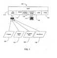
- a multipurpose host system 100is, by way of example, a personal computer architecture-based system for assessing real-time invasive cardiovascular parameters from within a blood vessel (e.g., blood pressure and flow measurements).
- the multipurpose hostprocesses input signals from multiple microminiature guide wire-mounted sensors (e.g., Doppler and pressure transducers) to produce real-time measurements, display various waveforms and derived parameters, and output high-level voltages proportional to calculated parameter values.
- the devices that supply the various data input signalsare represented by pressure input 102, velocity flow input 104, volume flow 106, and temperature input 108.
- the devices that provide the input to the host system 110are presently used in existing, special-purpose processing boxes.
- the host system 100operates in a plurality of modes, and each mode includes its own distinct graphical interface (rendered on graphical output display 110) and input parameter values (provided via a peripheral component interconnect (PCI) card 112) corresponding to particular sensor types.
- the PCI card 112includes, by way of example, a digital signal processor (DSP) that samples data provided by the communicatively coupled input sensors and processes the sampled data to render digital data in a format expected by higher level components of the host system 100. Exemplary processes performed by the DSP include: A/D and D/A conversions, FFTs, level shifting, normalizing, and scaling. After processing the data, it is stored in a dual port RAM accessed, via the PCI bus of the host 100, by higher level application processes executing on the host system 100.
- DSPdigital signal processor
- input sensor types driving the output displaysinclude pressure, flow, and temperature sensors mounted upon a flexible elongate member including combinations thereof placed, for example, upon a single guide wire or catheter.
- the flexible module-based architecture (see, FIG. 2 ) of the exemplary host system 110which supports simultaneous display of multiple distinct types of input signals on a single graphical user interface, is particularly well suited for such combination devices since their output can be simultaneously monitored on a single interface even though modules that process the sensor inputs execute independently within the host system 100.
- the exemplary host system 100operates in pressure, flow, and combination (pressure/flow) modes. Though not essential to the invention, operation of each mode is preferably independent of the other modes, and each diagnostic display mode is driven by a designated set of parameter generation modules associated with particular input signals received by the host system from a communicatively coupled sensor.
- the pressure modeprovides the user with a selection of calculated/derived parameters such as for example: proximal-distal pressure gradient, distal/proximal pressure ratio, normalized pressure ratio, and fractional flow reserve (normalized pressure ratio under hyperemic conditions).
- the flow modeis divided into three operational modes: peripheral, coronary, and research.
- the peripheral modeacquires measurements in the cerebral or peripheral vasculature.
- the coronary modeacquires measurements in the coronary arteries.
- the research modeprovides a superset of peripheral and coronary modes plus additional parameters that may be of interest in a clinical research environment.
- the combination modeallows parameters associated with pressure and flow modes to be displayed simultaneously on a single graphical display.
- the graphical display interface 110depicts calculated pressure and flow information on a strip chart graph on a graphical user interface display.
- the current valuesare, for example, displayed numerically as well.
- the graphscrolls as new information is calculated and added.
- a graphically displayed controlenables a user to freeze the scrolling graphs and scroll backwards to view previously displayed portions of the scrolling graph. Additional display methods and techniques will be apparent to those skilled in the art.
- the host system 100embodies an extensible, component-based architecture, and thus the host system 100 supports a virtually limitless number of operating modes for processing and rendering graphical display output corresponding to an extensible set of input signals provided by sensors measuring a variety of types and combinations thereof.
- the host system 100is modularized to support receiving and processing signals in a variety of formats from a variety of instruments.
- the host system 100relies on transducers and external diagnostic instrumentation to: (1) process the raw sensor information rendered by transducers/sensors inserted within a patient and (2) provide the information to the host 100 in particular digital or analog formats.
- the host system 100's capabilitiesare extendable, by way of example through enhancements to a currently installed peripheral component interconnect (PCI) board 110 or the addition of new PCI boards, to include additional signal processing capabilities.
- PCIperipheral component interconnect
- transducers on the guide wireprovide low-level signals for blood velocity, flow, and pressure.
- a standard external pressure transducermay be integrated with the host system to provide low-level aortic pressure.
- a high-level ECG signal input to the hostprovides synchronization for calculations (not patient isolated).
- the interface of the host system 100comprises a number of additional interfaces supporting the transfer and storage of information relating to the operation of the host system.
- Data storage device 114for example, a CD-RW or a DVD-RW drive, is utilized to upload new software and store patient data processed and displayed during a diagnostic/treatment procedure.
- a network interface 116provides remote access for performing functions similar to those provided by the data storage device 114.
- An audio input 118enables annotation of input records by a user.
- a printer 120facilitates printing out labels and/or compiled data from a diagnostic/treatment procedure.
- the set of peripheral/interface components identified in FIG. 1is exemplary. As those skilled in the art will readily appreciate there exist a vast variety of I/O devices that can be advantageously incorporated into the host system 100 to enhance its utility.
- FIG. 2depicts an exemplary internal architecture of the host system 100 that facilitates operation of the host 100 in a variety of display modes associated with a variety of sensed invasive cardiovascular parameters such as temperature, pressure and blood flow within an artery.
- the PCI card 112represents a highly flexible component of the host system 100 architecture.
- the PCI card 112includes a set of external sensor interface circuits for transmitting power and excitation signals to sensor devices and receiving sensed parameter values illustratively depicted in FIG. 2 .
- the PCI card 112includes both analog and digital input and output signals. Analog output signals are driven by the PCI card 112 output circuitry according to control commands supplied by high level user mode processes executing on the host system 100.
- the host system 100is not limited to any particular type of sensor input. To the contrary, the present host system 100 is intended to provide a broad, extensible, multipurpose platform upon which a wide variety of application-specific modules are capable of processing and displaying sensor data rendered by a variety of sensor types and combinations of the sensor types including those described, by way of example herein.
- the PCI card 112includes a digital signal processor (or DSP) 200 that operates as a special purpose co-processor on the host system 100.
- the DSP 200receives digital samples corresponding to signals received via external inputs to the PCI card 112, and carries out appropriate processing (e.g., FFT, filtering, scaling, normalizing, etc.) on the digital/digitized data samples. Thereafter, the processed data is placed into a dual port RAM within the PCI bus interface 202.
- DSPdigital signal processor
- Kernel mode drivers 204 executing on the host 100facilitate communicating commands and data between the PCI card 112 and a set of user mode processes 206 that drive input parameter values for the multiple graphical user interface modes supported by the host system 100.
- the kernel mode drivers 204communicate with the PCI bus interface 202 according to a set of methods defined by a PCI Application Program Interface (API) 212.
- the kernel mode drivers 204access PCI registers and ports on the PCI bus interface 202 to extract processed sensor data and to issue control commands to the PCI card 112.
- the kernel mode driver 204carries out other desired driver functionality including issuing startup and diagnostic commands to the PCI card 112 and enabling and disabling particular inputs and outputs of the PCI card 112.
- the PCI API 212are sufficiently generalized such that the PCI card 112 can be replaced by a different PCI card that includes a different set of input/output interfaces without requiring replacement of the presently installed kernel mode drivers 204 - though reconfiguration may be required to set up new connections between the kernel mode drivers 204 and sources and recipients of data and commands in the PCI interface 202.
- the kernel mode drivers 204also includes functional components that respond to interrupts generated by the PCI card 112 (e.g., data ready, hardware errors, etc.). Other exemplary functions performed by the functional components of the kernel mode drivers 204 include detecting PCI installed devices, retrieving information about installed devices, read/write data from/to PCI configuration registers, execute a single read/write operation to an I/O port or memory on the PCI interface 202, set up interrupt handling, allocate resources, and store sensor device-specific data.
- the functional driver module 214responds to new data available for submission to user mode processes (described herein below) responsible for rendering input data that drives the user mode graphical user interface (e.g., graphs, instantaneous parameter values for pressure and flow velocity, etc.).
- the user mode level of the host 100embodies a modular/component based architecture.
- the modular architectureprovides a high degree of flexibility in developing and incorporating new sensor types, and corresponding graphical user interfaces, into the multimode host user interface.
- the user mode processes 206include an extensible COM-based host application 222 that is responsible for presentation of a multiple interface mode graphical user interface (preferably with touch screen functionality).
- the host application 222instantiates a set of user interface mode objects from a registry of available user interface mode object classes. Examples of such user interface mode objects include Pressure, Flow, and Combination.
- Extension of a base set of graphical user interfaces to include new user interface modes, such as Temperature and pH,is achieved by installing one or more new DLLs containing a user interface mode class objects corresponding to new user interface modes.
- a separate user interface mode component objectis provided for each distinct user interface mode supported by the host application 222.
- the set of user mode processes 206also include a set of measurement processing components 224.
- each measurement processing componentcorresponds to a particular sensor.
- the measurement processing components 224are instantiated from a set of sensor-specific component object model (COM) objects provided by one or more dynamically linked library (DLL) files.
- COMsensor-specific component object model
- DLLdynamically linked library
- the above-described COM approach to sensor data handling at the user mode level 206also enables the set of input sensors and corresponding displayed interfaces to be readily extended by installing new DLLs from which the host system 100 instantiates COM objects corresponding to the new sensor input types.
- the illustrative host system 100 depicted in FIG. 2includes the following sensor-specific components: pressure 226, flow velocity 228, flow volume 230, temperature 232, and auxiliary 234.
- An exemplary input processed by the auxiliary component 234is a position signal rendered by one or more displacement sensors (e.g., a rotational position, a lengthwise position along a vessel).
- the sensor-specific componentsare described further herein below. Additional component types of components in the set of measurement processing components 224 (e.g., temperature, pH, etc.) in accordance with alternative embodiments of the host system 100.
- the set of sensor-specific componentsis extensible.
- the set of measurement processing components 224is extended by developing and dynamically incorporating a new sensor-specific component object. Thereafter, integration of the new sensor-specific component object is achieved by properly identifying the object as a member of the class of sensor-specific measurement processing components 224 that are instantiated when the system 100 starts up.
- the set of measurement processing components 224receive sensor data retrieved from the PCI interface 202 and drive inputs to particular ones of the graphical user interface display modes supported by the host application 222.
- the communications with the kernel mode processes 204are carried out via a sensor component API 238 which enables the measurement processing components 224 to communicate with an application logic component 240.
- the sensor component API 238 methodsare function oriented. An exemplary set of such methods in the sensor component API 238 include: setting operational states of the sensors, extracting sensor data, issuing control commands to the PCI card 112 configuring/controlling operation of the sensors.
- the application logic component 240translates calls issued by ones of the set of measurement processing components 224 into calls to the kernel mode drivers 204.
- the application logic component 240passes sensor data (originating from the PCI interface 202) from the kernel mode drivers 204 to the measurement processing components 224. Communications between the application logic component 240 and the kernel mode drivers 204 accessing the DSP 200 and the PCI interface 202 are carried out in accordance with a digital signal processing (DSP) API 242.
- DSPdigital signal processing
- the methods of the API 242are hardware oriented, and include, by way of example: handling an interrupt, writing DRAM, writing DRAM, starting and stopping particular DSP functions relating to particular sensors and/or interfaces.
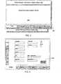
- FIG. 3depicts an exemplary generic graphical user interface specification upon which a set of graphical displays are based in accordance with the various graphical user interface modes supported by the host application 222.
- the exemplary graphical user interface architectureconsists of three dedicated data display regions.
- a first region 300is reserved for display of system and patient information.
- a second region 302is reserved for system messages.
- a third regioncontains a set of hierarchical screens including a set of functionally related display and interactive components accessed, by way of example, by selection of one of a set of tabs 306.
- the first region 300is persistent and is displayed during all modes of operation of the host application 222.
- the first region 300includes one or more of the following fields relating to a patient/session: Patient Name, Patient ID - customer specific identification number, Physician - name of the attending physician, Institution - name of the client institution using the system, Date/Time - current date and time, and a branding logo.
- the second region 302 of the exemplary graphical user interface general layoutis reserved to display system messages.
- the second region 302also persists for all modes of operation.
- the second region 302includes, by way of example, the following fields relating to the display of messages generated by the host system: Current status - a message indicating the current operation state or status of the unit; Warning events - a message advising the user of a potential problem and possible remedy; Error events - a message notifying the user of a system error and possible corrective action; and System Mode - a message notifying a user of the current mode of operation of the host 100.
- a third region 304is reserved to display parameters and input/output data fields according to a current mode of operation of the host 100 and display mode of the host application 222.
- the third region 304is not persistent. Rather, the content of the third region 304 is determined by a particular use mode within which the host application is operating.
- the third region 304operates in one or more of the following modes: System, Pressure, Flow, and Combo (Combination). Additional modes are supported/displayed by the host application 222 in accordance with alternative embodiments of the host 100. Such additional modes accommodate, for example, displaying additional sensor-provided/derived output parameters (e.g., temperature, pH, etc.) or new sets/combinations of previously existing output parameters display elements.
- Each modeincludes at least a second level of screens once the mode is selected by means of the tabs 306.
- FIG. 4an exemplary graphical user interface is displayed that is suitable for entry of patient information in accordance with the System mode of operation of the host application 222.
- the displayed graphical displaycorresponds to a user (patient) data entry sub-screen under the System mode.
- the host 100supports input of data using traditional keyboard, in an embodiment of the invention, the user enters, edits, and/or deletes patient information via a touch screen keyboard called up by selecting the keyboard button 400.
- FIG. 5in response to a user selecting the keyboard button 400, the graphical user interface depicted in FIG. 4 is modified to include a touch screen keyboard 500. Alternatively, keyboard 500 is provided automatically.
- the information enteredwill persist for the duration of the current session.
- the Patient/System Information Display area(the first region 300) reflects changes in corresponding fields.
- FIG. 6comprises an exemplary system sub-screen under the System mode.
- the userenters relevant system information, e.g., customer/institution name 602, time/data 603, printer 604, LAN connection, local data storage 606, and/or a Doppler audio volume 608.
- the system sub-screen depicted in FIG. 6preferably also includes a button/control 610 enabling a user to initiate a system self-test.
- the user specified information/configurationpersists indefinitely and spans multiple patient sessions.
- the Patient/System Information Area(the first region 300) reflects changes entered via this interface.
- FIG. 7comprises an exemplary system setup sub-screen 700 under the System mode of the host application 222. While the system setup interface enables a user to modify default settings, the new default settings are stored in a non-volatile file, persist indefinitely, and span multiple patient sessions. The default settings are applied on system startup and reapplied via a reset button. As depicted in FIG. 7 , the system setup sub-screen includes a new patient button 702 that invokes an interface enabling a user to enter new default setting for a new patient. A save patient study button 704 enables a user to store a session to a persistent device. A recall button 706 invokes an interface enabling a user to review and recall stored sessions. A reset system button 708 when selected, resets system information to default settings.
- a new patient button 702that invokes an interface enabling a user to enter new default setting for a new patient.
- a save patient study button 704enables a user to store a session to a persistent device.
- a recall button 706invoke
- a series of service selection buttons 710enable a research mode of operation of the host system 100, enable data logging, commence diagnostics on the host 100, and enable selection of parameters displayed.
- a Cath Lab ID 712allows the specification of a previously stored particular configuration/setup based, for example, upon a particular catheter lab within which the host 100 is to be used. However, the Cath Lab ID 712 field can be used to recall settings of any particular previously stored configuration/set up of the host 100.
- a mean period field 714allows an operator to designate the number of cardiac cycles that are used to calculate a single average value (e.g., Average Peak Velocity).
- FIG. 8comprises an exemplary network communications setup sub-screen 800.
- the sub-screenenables a user to provide information regarding report storage and transfer, connectivity, and format.
- a userinterfaces to a DICOM (Digital Imaging and Communication in Medicine, an exemplary format for data exchange between two different systems) compliant information management system via the DICOM sub-screen 800 interface of the system mode of the host application 222.
- DICOMDigital Imaging and Communication in Medicine
- Other services provided by the DICOM sub-screen interfaceinclude transferring images to a remote DICOM archive and recalling images from the remote DICOM archive.
- the fields of the sub-screen 800include a patient name 802, an application entity title 804 for specifying the DICOM nodes with which the host 100 communicates, a TCP port field 805 specifies a port through which communications will take place, an Internet protocol address 806 identifying the address of the computer on the network with which the host 100 communicates, local DICOM storage location 808 specifies the local directory where the host 100 stores DICOM files, a browse button 810 launches a well known utility to search within the host 100's directory structure or create a new directory, storage file format 812 enables a user to select a file storage format (e.g., DICOM, proprietary, etc.), and a configure button 814 launches configuration of the communications based upon the specified field data.
- a file storage formate.g., DICOM, proprietary, etc.
- the host application 222includes a pressure mode setup sub-screen 900 that enables a user to specify particular display attributes associated with a display sub-screen (see FIG. 10 ).
- the pressure setup sub-screen 900preferably provides the user with input features to customize the operation of the pressure mode.
- the illustrative pressure mode setup sub-screen 900includes a set of low and high level input calibration controls 902a and 902b enabling a user to calibrate a pressure sensor in a variety of ways.
- the zero button in the calibration control displays 902a and 902bfacilitates establishing a zero reference for the pressure sensor and a zero output level reference for any external instruments.
- Zero level calibrationis performed by applying a zero pressure (ambient) and selecting the zero button on the calibration controls 902a and 902b.
- low level input calibrationis achieved through the low level input calibration control 902a by applying a low pressure input, setting adjusting the scale value to the input pressure, and then pressing the set button.
- a high level input calibrationis achieved through the high level input calibration control 902b by applying a high pressure input, setting adjusting the scale value to the input pressure, and then pressing the set button.
- the low and high pressure calibrationis alternatively performed by pressing the button labeled "scale value” to enable calibration by establishing a zero pressure and providing a "slope” or calibration factor defining the relationship between changes to the input pressure and the input signal.
- the button labeled "scale value”actually toggles the calibration mode, and in response the calibration display 902a or 902b converts to a calibration factor mode.
- a calibration factor expressed in terms of microvolts per mmHgis entered by adjusting a displayed value and then pressing the set button.
- the pressure mode setup sub-screen 900also includes a distal input normalization control 903 for normalizing input pressure measurements from a distal pressure sensor via touch screen button controls. Normalization is the matching of the guide wire pressure sensor reading with an aortic pressure. Normalization is achieved by bringing the pressure sensor to an appropriate location and selecting the normalization button. This establishes a new value for the aortic pressure that is used to determine various calculated/displayed output parameter values, including FFR. A distal sensor zero reference is established by selecting the zero button in the distal input normalization control 903 while applying a zero pressure reference.
- the pressure mode setup sub-screen 900also includes a set of venous pressure controls 904 including a venous pressure source control and venous pressure adjust (up/down) controls.
- a mean venous pressure valueenables computing an FFR.
- the mean venous pressuremay be input from a transducer via an external monitor or by a user preset value. Selecting the venous pressure source button on the setup sub-screen 900 toggles the source. Selecting 'External' designates the venous pressure source as a patient-applied transducer through an external monitor. Selecting 'Preset' allows the user to enter an assumed value. Selecting the up/down controls increases/decreases the preset value accordingly.
- the preferred range of values for the venous pressureis about 0 - 50 mmHg.
- An analog output offset adjust 906provides an interface for a user to adjust the offset and the pressure high level analog output of the host system 100.
- the usercan increase or decrease the output via the user interface.
- the outputdisplays the current output adjustment level via the user interface.
- the analog outputis modified accordingly. Change is effected by selecting the Up/Down arrow buttons adjacent to the Offset Adjust display to increase/decrease the value accordingly.
- the valuewill change, for example, in steps of 1 mmHg.
- the preferred range of valuesis about -30 to 330 mmHg.
- the setup sub-screen 900also includes maximum/minimum scaling presets 908 for both distal and proximal pressures.
- An on/off buttonenables/disables an autoscaling feature of the host graphical output display for the proximal and distal pressures. When autoscaling is activated, the scale of the output display expands as needed to handle an increased range of output pressures.
- a toggle button displayed in the "adjust" state for both proximal and distal scaling,enables manual adjustment of the maximum and minimum scale values using the up/down arrow buttons.
- the pressure graph depicted in FIG. 10 in the display sub-screen for the pressure modereflects the designated scales.
- an exemplary pressure mode display sub-screen 1000displays data and pressure mode controls.
- the data driving the pressure displayis supplied by the pressure component 226 of the set of measurement processing components 224 identified in FIG. 2 .
- the exemplary pressure mode display sub-screen 1000includes a pressure waveform graph 1002 including multiple pressure waveforms including distal, venous, and aortic pressure waveforms.
- a run/freeze control 1004stops and starts scrolling.
- a cursor/position control 1006facilitates searching a waveform.
- a calculation mode control 1008includes a first button for selecting a pressure calculation mode (e.g., distal/proximal gradient, distal/proximal ratio, normalized pressure ratio (NPR), and fractional flow reserve (FFR)) and a second button to search for peaks (visible only in FFR mode and used to detect peak hyperemic response after injecting a hyperemic agent).
- a pressure calculation modee.g., distal/proximal gradient, distal/proximal ratio, normalized pressure ratio (NPR), and fractional flow reserve (FFR)
- a second buttonto search for peaks (visible only in FFR mode and used to detect peak hyperemic response after injecting a hyperemic agent).
- the exemplary pressure display sub-screen 1000also includes a set of instantaneous/current measurement digital displays 1010 including: distal pressure, aortic pressure, venous pressure, and a selected calculated value (e.g., distal-to-proximal gradient, distal-to-proximal ratio, NPR, FFR).
- a print button 1012initiates printing a set waveforms recorded during a session. Recording of the waveforms is toggled on/off by means of the record button 1014.
- a gradient outputis measured by taking a difference between pressures before (e.g., aortic) and after a partially blocked vessel.
- the distal-to-proximal ratiois calculated by dividing the distal pressure by the proximal pressure.
- the normalized pressure ratiois calculated by subtracting the venous pressure from the distal and proximal pressures and then taking their ratio.
- the FFR valueis calculated by taking the normalized pressure ratio at the peak hyperemic response. Pressure gradients/ratios across a heart valve are also provided in association with yet another potential calculated value rendered by the host 100.
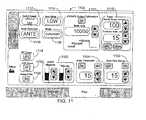
- a setup screen 1100provides the user with interface setup features to select and customize the operation of the flow mode of operation of the host 100.
- the flow setupincludes controls to set for example: Doppler audio volume and balance 1102 - for a set of stereo speakers, a signal threshold 1104 - via an on/off button and a threshold adjust, and velocity range 1106 - similar to pressure in that a user can select either auto ranging or manually adjust the maximum on the scale in the case where the auto ranging is shut off.
- a configuration button 1108toggles between coronary and peripheral artery configurations to take into consideration the delay of velocity changes in relation to an ECG signal.
- Trend setup controls 1110set velocity scale and time base scale for a trend output. Furthermore, the trended parameter, average peak velocity or diastolic/systolic velocity ratio, is selected via the trend setup controls 1110.
- Other exemplary controls for the flow display modeinclude a sweep speed 1112 (selects the scrolling speed of the spectral display from 3 speeds: slow, medium, or fast), zero offset 1114 (selects the zero velocity baseline position from 3 locations: low, medium, or high), and a flow direction 1116 (select the direction of flow to be displayed above the baseline from 2 bearings: antegrade or retrograde).
- a usercan also optionally designate whether to display a blood pressure trace 1118, ECG trace 1119.
- a useralso selectively activates a noise filter 1120.
- a calibration section 1122allows a user to enable/disable an output calibration signal and select the particular waveform for performing the calibration.
- a set of illustrative examples of a flow displayare provided in accordance with two primary flow sensing configurations, coronary and peripheral - as designated by the configuration button 1108 on the flow setup sub-screen depicted in FIG. 11 .
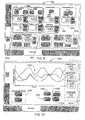
- a flow operation sub-screen 1200is displayed in its depicted state when a CFR operation button 1201 button is selected.
- a multi-partitioned waveform displaydepicts a full wave form graph 1202 as well as two smaller waveform display output segment graphs 1204 and 1206 corresponding to the base waveform and peak wave form (under hyperemic conditions).
- the designation of the time frame in which data is gathered and displayed within the graphs 1204 and 1206is determined by pressing the base/peak button 1208 a first time to acquire the base readings and then pressing the base/peak button 1208 a second time to acquire the peak readings.
- the graphs 1202, 1204 and 1206display flow velocity (based upon flow velocity input data in the form of Doppler spectral arrays), measured in a variety of ways (e.g., average peak velocity, mean peak velocity and flow velocity).
- a set of grayscale valuesare assigned to each representative frequency component of the display. Intensity is assigned to points along a same time slice on the graph based upon prevalence of the frequency indicative of blood flow velocity.
- the displaygenerates a set of markers associated with particular sensed events. For example, the "S" represents the systolic pressure reading while the "D" represents the diastolic pressure reading in a cardiac cycle.
- a usercan limit the displayed spectra by adjusting the threshold background 1104 to exclude low level frequency components. Simultaneous with the velocity spectra, an instantaneous peak velocity tracking the blood flow velocity envelope's peak may also be displayed.
- instantaneous/current calculated values for graphed parametersare digitally displayed as well in field 1210.
- field 1210displays the instantaneous heart rate, average peak velocity (APV), and diastolic/systolic velocity ratio (DSVR). Additional sub-fields of field 1210 depict the APV and DSVR determined during a designated base time span and peak time span. Field 1210 also displays the CFR calculated from the base and peak values.
- An optimal wire position indicator 1212visually prompts a user to move the wire to obtain optimal placement positioning.
- a run/freeze button 1214starts and stops scrolling of the displayed waveforms, and a cursor 1215 allows scrolling within the previously displayed sections of the waveforms.
- a print button 1216enables the printing of the waveforms.
- a record button 1218toggles a data/waveform recorder between an active/inactive logging state.
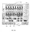
- FIG. 12bdepicts the display of the host system 100 when a user selects the proximal/distal button 1220 while in the coronary flow configuration. Instead of the base/peak button 1201, a proximal button 1222 and a distal button 1223 are displayed.
- the proximal button 1222is selected to invoke pressure input processing by the host system 100 corresponding to a pressure observed proximal (before) a stenosis.
- the corresponding waveformis displayed upon a graph 1224.
- the distal button 1223is selected to invoke pressure input processing corresponding to a pressure observed distal (after) a stenosis.
- the corresponding waveformis displayed upon a graph 1226.
- the output display depicted in FIG. 12bincludes instantaneous/current calculated values for graphed parameters in field 1228.
- field 1228displays the instantaneous heart rate, average peak velocity (APV), and diastolic/systolic velocity ratio (DSVR). Additional sub-fields of field 1228 depict the APV and DSVR determined for proximal and distal pressure readings. Field 1228 also displays the proximal/distal ratio calculated by the host 100 from the observed proximal and distal pressures.
- APIaverage peak velocity
- DSVRdiastolic/systolic velocity ratio
- FIG. 12cdepicts a graphical output display rendered in accordance with trend calculations supported by the host system 100.
- the host system 100calculates an average flow velocity value (e.g., APV, DSVR, etc.) over a period of time (e.g., a cardiac cycle) and visually renders the value in the form of a graph 1230.
- the trend modeis entered when a user selects a trend button 1231.
- an APV button 1232 and a DSVR button 1234are displayed. Based upon a user's selection, the calculated and displayed average is either an APV or a DSVR.
- the above two trend parametersare merely exemplary as those skilled in the art will readily appreciate that other input/calculated are suitable for trend calculation, display and analysis.
- a set of instantaneous/current calculated values for graphed parametersare digitally displayed in field 1236.
- the output parameters displayed in field 1236are the same as the ones depicted in field 1210 in FIG. 12a .
- the BASE, Peak and CFR parametersare not calculated by the host 100 while trend analysis is occurring. Rather, these parameters are retrieved, if they exist, from previous calculations rendered when the user selects the CFR button 1201.
- the base valueis marked in the trend graph 1230 with a "B", the peak value with a "P”, and the starting point of the peak search with an "S”.
- the time scale of the trend graph 1230is on the order of one or multiple minutes.
- the time scale of the ECG graph above the trend graphis on the order of seconds.
- FIGs. 12d and 12egraphical display outputs are illustratively depicted for two exemplary peripheral operations supported by the host 100. These two sub-screens of the flow mode graphical display 1200 are entered by selecting the peripheral configuration through the coronary/peripheral configuration button 1108 on the flow setup sub-screen depicted in FIG. 11 .
- the peripheral configurationtakes into account that, in peripheral arteries, a flow velocity signal lags an ECG signal, and therefore the peripheral configuration introduces a time shift to account for the lag.
- FIG. 12dillustratively depicts the display 1200 when the ratio button 1240 is selected while the host system 100 is in the peripheral flow configuration.
- a graph 1242displays a continuous graph depicting calculated flow velocity.
- a base flow velocity graph 1244is rendered from data collected by the host system 100 after a base/peak button 1246 is selected a first time.
- a peak flow velocity graph 1248is rendered from data obtained after the base/peak button 1246 is selected a second time.
- instantaneous/current calculated values for graphed parametersare digitally displayed as well in field 1250.
- field 1250displays the instantaneous heart rate, APV, and mean peak velocity (MPV). Additional sub-fields of field 1250 depict the APV and MPV determined during a designated base time span and peak time span. Field 1250 also displays a ratio calculated from the base and peak values.
- FIG. 12eillustratively depicts the display 1200 when the trend button 1252 is selected while the host system 100 is in the peripheral flow configuration.
- the two snapshot graphs 1244 and 1248are replaced by a single trend graph 1254.
- instantaneous/current calculated values for graphed parametersare digitally displayed as well in field 1256.
- field 1256displays the instantaneous heart rate, APV, and mean peak velocity (MPV). Additional sub-fields of field 1256 depict the APV and MPV determined during a designated base time span and peak time span.
- Field 1256also displays a ratio calculated from the base and peak values. However, the displayed Base, Peak and ratio values in field 1256, are provided from the previously described ratio operation described with reference to FIG. 12e .
- Yet another exemplary mode of the multiple interface modesis a combination mode that provides data from multiple sensors in a single graphical interface.
- the combination modeincludes additional sensor input types such as, for example, a temperature input or a position sensor.
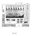
- FIG. 13provides an exemplary combination mode display in which flow and pressure measurements are combined to render two side-by-side scrolling graphs depicting sensed flow and pressure parameters during an invasive diagnostic procedure wherein a flexible elongate member such as a guide wire, configured as a combination device (in this particular case including both a pressure sensor and a Doppler flow sensor) is inserted into a patient.
- Such combination devicesused in association with the combination output provide a desirable environment in which to calculate fractional flow reserve (FFR) using pressure readings, and coronary flow reserve (CFR) using flow readings.
- FFRfractional flow reserve
- CFRcoronary flow reserve
- the combination mode display screen 1300includes a first graph 1302 of sensed pressure and a second graph 1304 of flow output parameters such as, for example, Doppler spectral arrays, average peak velocity and flow volume.
- Digital displaysare provided that illustratively indicate instantaneous measurements for distal pressure 1306, a pressure calculation (based upon selected calculation via button 1316) such as gradient pressure 1308 (but also displays FFR or other calculated pressures), heart rate 1310, average peak flow velocity 1312 and mean peak flow velocity 1314.
- a CFR/Trend button 1320provided a user the capability of selecting a CFR operation or trend operation in association with the acquisition of flow data.
- a flow velocity button 1321enables selection of a flow velocity output mode. As disclosed previously in FIGs. 10 and 12a -e the screen 1300, in an embodiment of the invention, reconfigures in association with a user's selection of the various selectable operations and calculations supported by the combination mode of the host 100.
- the combination screen 1300also preferably includes scroll controls in the form of scrolling arrows 1322 that enable a user to scroll forward and back along the graphical output.
- a freeze/run toggle button 1324enables/disables scrolling of the graphs 1302 and 1304.
- a print button 1326initiates printing a session (or portion thereof).
- a record button 1328commences and halts recording session data in a toggling manner.
- the host 100preferably supports interactive remote control/selection of the various display components depicted in the exemplary graphical user interface displays described herein above.
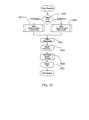
- FIG. 14depicts a flowchart summarizing an exemplary set of steps for carrying out a coronary flow reserve (CFR) measurement.
- a userselects the flow interface mode of the host application 222.
- the userpresses the CFR button 1201 on the display screen to measure CFR.
- the graph area of the screen 1200vertically partitions into upper and lower halves.
- the upper half graph 1202displays the real-time velocity spectra presently measured by the Doppler sensor.
- the lower half of the graph display areais divided horizontally into two sections for displaying snapshots of the spectral display taken from the upper partition.
- the lower left areacontains baseline graph 1204, and the lower right area is reserve for a peak response graph 1206.
- step 1404a user presses the BASE/PEAK button 1208 on the display 1200 to save the baseline spectral display.
- a snapshot of the real-time spectral displayis transferred to the lower left (baseline) graph 1204 of the display during step 1406.
- a hyperemic agentis injected into the patient.
- the BASE/PEAK button 1208is selected a second time.
- the host application 222automatically begins a search for a peak hyperemic response (maximum average peak velocity (APV) - where the APV is determined by averaging the instantaneous peak velocity (IPV) over a cardiac cycle).
- ADVpeak hyperemic response
- IPVinstantaneous peak velocity
- step 1414a snapshot of the real-time spectral display is transferred to the lower right (peak) area on the graph 1202.
- the CFR ratiois periodically recalculated based upon the maximum APV found during the search and the current maximum ratio is displayed digitally in field 1210.
- the searchis automatically terminated if 5 consecutive seconds have elapsed and the maximum APV has not changed.
- the last CFR ratio valueis held in the display as the process for determining the CFR ratio ends.
- step 1500an exemplary set of steps for carrying out a fractional flow reserve (FFR) determination using the host system 100 in a pressure mode and a guide wire including a pressure transducer is summarized.
- the FFR modeis selected via the calculation mode button of the calculation mode control 1008.
- a blood pressure sensoris placed in position to measure distal pressure within a vessel.
- Aortic pressureis simultaneously monitored using an aortic pressure sensor.
- step 1501 or 1502(based upon the specifically selected FFR mode - intracoronary or intravenous) the hyperemic agent is either injected in the blood vessel under investigation or administered intravenously.
- the peak search button of the calculation mode control 1008(displayed only for FFR mode) is selected to observe the hyperemic response of the vessel during step 1504.
- the host application 222displays a "searching" prompt at step 1506 until it locates a peak response while carrying out a search during step 1508.
- the FFR valueis displayed during step 1510 on the display 1000.
- the pressure mode of operation of the host application 222preferably also supports determination of a proximal/distal ratio.
- the set of exemplary steps for such a procedureare depicted in FIG. 16 .
- the P/D modeis selected via the calculation mode button of the calculation mode control 1008. This results in a split screen similar to the one described above for the CFR ratio determination process summarized in FIG. 14 .
- a userselects a proximal button that is displayed when the ratio calculation operation is selected.
- the host application 222stores the current proximal image in the lower left quadrant of the graph 1002 (in a split screen similar to the one displayed for CRF operations).
- a pressure sensor of the guide wireis moved to a point beyond (distal to) a stenosis during step 1606.
- a distal display button rendered within the calculation mode control 1008 areais selected on the graphical display screen 1000.
- the host application 222stores the current distal image in the lower right quadrant of the graph 1002.
- the proximal/distal pressure ratiois calculated based upon the stored inputs at steps 1604 and 1610, and during step 1614 the P/D ratio is displayed on the display 1000.
- the ordering of taking the proximal and distal readingsis not important to carry out the P/D ratio determination.
- the readingsare taken at substantially the same time.
- the host system 100receives pressure sensor signals and a sensor displacement signal enabling the host system 100 to render a map of pressure variations along a vessel.
- the resulting substantially real-time graphical displaycan be used, for example, to locate a stenosis or guide optimal placement of treatment of a vessel blockage.
- a position sensors identifying angular displacement as well as displacement along the length of a vesselare integrated, by the host system, with a temperature sensor mounted upon a flexible elongate member to provide a temperature map for the walls of a vessel to identify lesions.
- a temperature mapis created by the host system 100 by rotating a temperature sensor placed against the vessel wall and drawing the temperature sensor back along the vessel.
- the host system 100receives and integrates the signals provided by the temperature and position sensors and renders a corresponding map.
Landscapes
- Health & Medical Sciences (AREA)
- Life Sciences & Earth Sciences (AREA)
- Engineering & Computer Science (AREA)
- Physics & Mathematics (AREA)
- Public Health (AREA)
- General Health & Medical Sciences (AREA)
- Medical Informatics (AREA)
- Biomedical Technology (AREA)
- Pathology (AREA)
- Heart & Thoracic Surgery (AREA)
- Molecular Biology (AREA)
- Surgery (AREA)
- Animal Behavior & Ethology (AREA)
- Biophysics (AREA)
- Veterinary Medicine (AREA)
- Nuclear Medicine, Radiotherapy & Molecular Imaging (AREA)
- Radiology & Medical Imaging (AREA)
- Cardiology (AREA)
- Physiology (AREA)
- Hematology (AREA)
- Optics & Photonics (AREA)
- Human Computer Interaction (AREA)
- Vascular Medicine (AREA)
- Electromagnetism (AREA)
- Epidemiology (AREA)
- Primary Health Care (AREA)
- Chemical Kinetics & Catalysis (AREA)
- Artificial Intelligence (AREA)
- Computer Vision & Pattern Recognition (AREA)
- Psychiatry (AREA)
- Signal Processing (AREA)
- Pulmonology (AREA)
- General Chemical & Material Sciences (AREA)
- Chemical & Material Sciences (AREA)
- Measuring And Recording Apparatus For Diagnosis (AREA)
- Measuring Pulse, Heart Rate, Blood Pressure Or Blood Flow (AREA)
- Measurement Of The Respiration, Hearing Ability, Form, And Blood Characteristics Of Living Organisms (AREA)
- Business, Economics & Management (AREA)
- General Business, Economics & Management (AREA)
Abstract
Description
- The present invention generally relates to the area of diagnostic medical equipment, and more particularly to diagnostic devices for identifying and/or verifying efficacy of treatment of problematic blockages within coronary arteries by means of sensors mounted upon the end of a flexible elongate member such as a guide wire.
- Innovations in diagnosing and verifying the level of success of treatment of cardiovascular disease have migrated from external imaging processes to internal, catheterization-based, diagnostic processes. Diagnosis of cardiovascular disease has been performed through angiogram imaging wherein a radiopaque dye is injected into a vasculature and a live x-ray image is taken of the portions of the cardiovascular system of interest. Magnetic resonance imaging (MRI) has also been utilized to non-invasively detect cardiovascular disease. Diagnostic equipment and processes also have been developed for diagnosing vasculature blockages and other vasculature disease by means of ultra-miniature sensors placed upon a distal end of a flexible elongate member such as a catheter, or a guide wire used for catheterization procedures.
- One such ultra-miniature sensor device is a pressure sensor mounted upon the distal end of a guide wire. An example of such a pressure sensor is provided in
Corl et al. U.S. Patent 6,106,476 , the teachings of which are expressly incorporated herein by reference in their entirety. Such intravascular pressure sensor measures blood pressure at various points within the vasculature to facilitate locating and determining the severity of stenoses or other disruptors of blood flow within the vessels of the human body. Such devices are presently used to determine the need to perform an angioplasty procedure by measuring blood pressure within a vessel at multiple locations, including both upstream and downstream of a stenosis and measuring a pressure difference that indicates the severity of a partial blockage of the vessel. - In particular, a guide wire mounted pressure sensor is utilized to calculate fractional flow reserve (or "FFR"). In the coronary arteries, FFR is the maximum myocardial flow in the presence of stenosis divided by the normal maximum myocardial flow. This ratio is approximately equal to the mean hyperemic (i.e., dilated vessel) distal coronary pressure Pd divided by the mean arterial pressure Pa. Pd is measured with a pressure sensor mounted upon a distal portion of guide wire or other flexible elongate member after administering a hyperemic agent into the blood vessel causing it to dilate. Pa is measured using a variety of techniques in areas proximal of the stenosis, for example, in the aorta.
- FFR provides a convenient, cost-effective way to assess the severity of coronary and peripheral lesions, especially intermediate lesions. FFR provides an index of stenosis severity that allows rapid determination of whether an arterial blockage is significant enough to limit blood flow within the artery, thereby requiring treatment. The normal value of FFR is about 1.0. Values less than about 0.75 are deemed significant and requiretreatment. Treatment options include angioplasty and stenting.
- Another such known ultra-miniature sensor device is a Doppler blood flow velocity sensor mounted upon the end of a guide wire. Such device emits ultrasonic waves along the axis of a blood vessel and observes a Doppler-shift in reflected echo waves to determine an approximation of instantaneous blood flow velocity. A Doppler transducer is shown in
Corl et al. U.S. Patent 6,106,476 on a guide wire that also carries a pressure transducer. Such devices are presently used to determine the success of a treatment to lessen the severity of a vessel blockage. - In particular, a Doppler transducer sensor is utilized to measure Coronary Flow Reserve (or "CFR"). CFR is a measure for determining whether a stenosis is functionally significant after treatment (e.g., post-angioplasty). CFR comprises a ratio of the hyperemic average peak velocity of blood flow to the baseline (resting) average peak velocity. Instantaneous peak velocity (IPV) is the peak observed velocity for an instantaneous Doppler spectrum provided by a Doppler transducer. An exemplary method of calculating an average peak velocity (APV) comprises averaging a set of IPV's over a cardiac cycle.
- A known technique for determining whether an angioplasty was effective was to perform angioplasty, wait a few days, then perform thalium scintigraphy (imaging). If the angioplasty procedure was not effective, then re-intervention was performed and the lesion was again treated via angioplasty. On the other hand, using CFR, a flow measurement is taken immediately after angioplasty or stenting. The flow measurement is utilized to determine whether adequate flow has been restored to the vessel. If not, the balloon is inflated without the need for secondary re-intervention. A normal CFR is greater than about 2 and indicates that a lesion is not significant. Lower values may require additional intervention. In addition to being used post-treatment to determine the efficacy of treatment, CFR may be measured prior to treatment to determine if treatment is required.
- A guide wire combination device, comprising a pressure sensor and a flow sensor having substantially different operational characteristics, was disclosed in the
Corl et al. U.S. Patent 6,106,476 . While it has been proposed within theCorl et al. U.S. Patent 6,106,476 to combine pressure and flow sensors on a single flexible elongate member, the prior art does not address how such a combination sensor is coupled to consoles that display an output corresponding to the signals provided by the flexible elongate member corresponding to the sensed pressure and flow within a vessel. Indeed, the relevant art comprises special-purpose monitors having static display interfaces that display a static set of parameters corresponding to a particular fixed set of diagnostic measurements (e.g., an aortic pressure and a pressure taken from a location proximate a stenosis). Thus, one type of monitor is utilized to process and display sensed pressure within a blood vessel. Another type of monitor provides output relating to blood flow within a vessel. As new intravascular diagnostic devices are developed, yet other special-purpose monitors/consoles are developed to display to a physician the sensed parameters. - There is substantial interest in simplifying every aspect of the operating room to reduce the incidence of errors. As one can imagine, the aforementioned intravascular pressure sensors are utilized in operating room environments including many types of sensors and equipment for diagnosing and treating cardiovascular disease. Clearly, the room for error is very limited when performing such activities. Notwithstanding the interest to keep equipment and operations simple, there exists a variety of different sensors that are potentially inserted within a human vasculature to diagnose arterial disease (e.g., blockages) and/or monitor vital signs during a medical procedure. The approach taken in the field of interventional cardiac imaging has been to provide multiple, special-purpose monitor consoles. Each monitor type is linked to a particular type of sensor device.
- In a known prior intravascular pressure sensor-to-physiological monitor interface arrangement, marketed by JOMED Inc. of Rancho Cordova, CA, a physiology monitor receives and displays, on a permanently configured display interface, a set of pressure values corresponding to two distinct pressure signals that are received by the monitor. A first pressure signal is provided by an aortic pressure sensor, and a second pressure signal corresponds to a pressure sensed by a distally mounted solid-state pressure sensor mounted upon a guide wire. The display interface of the monitor is permanently configured to output parameter values corresponding to those two signals. Thus, if display of, for example, a flow signal value is desired, then a separate monitor, such as JOMED Inc.'s FloMap, is used.
- The present invention provides addresses a need to provide a flexible, multipurpose host system for processing and displaying signals rendered by invasive cardiovascular sensors to reduce the amount of equipment and complexity of procedures for diagnosing and determining the efficacy of treatment of cardiovascular stenoses.
- In particular, the present invention comprises a multipurpose host system that facilitates invasive cardiovascular diagnostic measurement acquisition and display. The host system includes a number of modularized components. The host system includes an external input signal bus interface for receiving data arising from cardiovascular diagnostic measurement sensors such as, for example, pressure transducers, Doppler flow transducers, temperature sensors, pH sensors, optical sensors, etc.
- The host system also includes a plurality of measurement processing components for receiving data of particular sensor types. The processing components render diagnostic measurement parameter values according to the received data arising from various types of attached sensors. In a particular embodiment, the processing components are instantiated at startup time from component modules that are dynamically integrated into the host system. This allows the functionality of the host system to be extended to include new types of sensors without requiring an overhaul of the existing system software.
- The host system also includes a multi-mode graphical user interface host. The interface host comprises a set of diagnostic measurement user interfaces. The output interfaces are integrated with the processing components and carry out displaying, on a graphical user interface a set of output values corresponding to parameter values rendered by the processing components.
- While the appended claims set forth the features of the present invention with particularity, the invention, together with its objects and advantages, may be best understood from the following detailed description taken in conjunction with the accompanying drawings of which:
FIG. 1 is a schematic drawing depicting a system for conducting invasive cardiovascular diagnoses including an external input signal interface for receiving diagnostic parameter values of multiple types and a multimode graphical user interface for presenting the values according to a user-selected one of the multiple display modes;FIG. 2 is a schematic drawing depicting an exemplary architecture of the system depicted inFIG. 1 ;FIG. 3 depicts an exemplary generic graphical user interface specification upon which a set of graphical displays are based in accordance with the various graphical user interface modes supported by a host system embodying the present invention;FIG. 4 depicts an exemplary graphical user interface for a patient data entry sub-screen of a system display mode of the host system;FIG. 5 depicts an exemplary graphical user interface for a user/patient data entry sub-screen of a system display mode of the host system that includes a keyboard;FIG. 6 depicts an exemplary graphical user interface for a system configuration sub-screen of a system display mode of the host system;FIG. 7 depicts an exemplary graphical user interface for a setup sub-screen of a system display mode of the host system;FIG. 8 depicts an exemplary graphical user interface for a communications subscreen of a system display mode of the host system;FIG. 9 depicts an exemplary graphical user interface for a setup sub-screen of a pressure display mode of the host system;FIG. 10 depicts an exemplary graphical user interface for a display sub-screen of a pressure display mode of the host system;FIG. 11 depicts an exemplary graphical user interface for a setup sub-screen of a flow display mode of the host system;FIGs. 12a-e depict an exemplary graphical user interface for a display sub-screen of a flow display mode of the host system;FIG. 13 depicts an exemplary graphical user interface for a combination flow and pressure display mode of operation of the host system;FIG. 14 is a flowchart summarizing a set of steps for carrying out a coronary flow reserve measurement using the multipurpose host system described herein;FIG. 15 is a flowchart summarizing a set of steps for carrying out a fractional flow reserve measurement using the multipurpose host system described herein; andFIG. 16 is a flowchart summarizing a set of steps for carrying out a proximal/distal pressure ratio measurement using the multipurpose host system described herein.- A multipurpose host system for invasive cardiovascular diagnostic measurement acquisition and display provides an advantage of the prior known systems in regard to its ability to present multiple user display interfaces. Each of the display interfaces corresponds to a particular purpose for which the multipurpose host is currently configured based, for example, upon one or more sensor devices communicatively coupled to its external signal interface. The host system is used, for example, in conjunction with interventional cardiology, e.g., angiography, or interventional procedures, e.g., angioplasty, to evaluate the hemodynamic status of an arterial blockage.
- With reference to
FIG. 1 , amultipurpose host system 100 is, by way of example, a personal computer architecture-based system for assessing real-time invasive cardiovascular parameters from within a blood vessel (e.g., blood pressure and flow measurements). The multipurpose host processes input signals from multiple microminiature guide wire-mounted sensors (e.g., Doppler and pressure transducers) to produce real-time measurements, display various waveforms and derived parameters, and output high-level voltages proportional to calculated parameter values. The devices that supply the various data input signals are represented bypressure input 102,velocity flow input 104,volume flow 106, andtemperature input 108. In an embodiment of the invention, the devices that provide the input to thehost system 110 are presently used in existing, special-purpose processing boxes. This set is exemplary, as those skilled in the art will readily appreciate in view of this disclosure that alternative systems advantageously receive and process such diagnostic inputs as pH, ultrasound and light-based cross-sectional images of a vessel, biochemical markers, light spectrometry for tissue characterization, etc. It is further noted that the displayed output of thehost system 100 is not limited to producing the measured parameters. Rather, the various modes of thehost system 100 are capable of synthesizing generalized measures of physiological status (e.g., whether a blockage is severe and needs treatment) based upon the input parameter values. - The
host system 100 operates in a plurality of modes, and each mode includes its own distinct graphical interface (rendered on graphical output display 110) and input parameter values (provided via a peripheral component interconnect (PCI) card 112) corresponding to particular sensor types. ThePCI card 112 includes, by way of example, a digital signal processor (DSP) that samples data provided by the communicatively coupled input sensors and processes the sampled data to render digital data in a format expected by higher level components of thehost system 100. Exemplary processes performed by the DSP include: A/D and D/A conversions, FFTs, level shifting, normalizing, and scaling. After processing the data, it is stored in a dual port RAM accessed, via the PCI bus of thehost 100, by higher level application processes executing on thehost system 100. - In the exemplary-embodiment, input sensor types driving the output displays include pressure, flow, and temperature sensors mounted upon a flexible elongate member including combinations thereof placed, for example, upon a single guide wire or catheter. In fact, the flexible module-based architecture (see,
FIG. 2 ) of theexemplary host system 110, which supports simultaneous display of multiple distinct types of input signals on a single graphical user interface, is particularly well suited for such combination devices since their output can be simultaneously monitored on a single interface even though modules that process the sensor inputs execute independently within thehost system 100. - The
exemplary host system 100 operates in pressure, flow, and combination (pressure/flow) modes. Though not essential to the invention, operation of each mode is preferably independent of the other modes, and each diagnostic display mode is driven by a designated set of parameter generation modules associated with particular input signals received by the host system from a communicatively coupled sensor. The pressure mode provides the user with a selection of calculated/derived parameters such as for example: proximal-distal pressure gradient, distal/proximal pressure ratio, normalized pressure ratio, and fractional flow reserve (normalized pressure ratio under hyperemic conditions). In an exemplary embodiment, the flow mode is divided into three operational modes: peripheral, coronary, and research. The peripheral mode acquires measurements in the cerebral or peripheral vasculature. The coronary mode acquires measurements in the coronary arteries. The research mode provides a superset of peripheral and coronary modes plus additional parameters that may be of interest in a clinical research environment. The combination mode allows parameters associated with pressure and flow modes to be displayed simultaneously on a single graphical display. - In the illustrative embodiment of the invention, the
graphical display interface 110 depicts calculated pressure and flow information on a strip chart graph on a graphical user interface display. The current values are, for example, displayed numerically as well. The graph scrolls as new information is calculated and added. A graphically displayed control enables a user to freeze the scrolling graphs and scroll backwards to view previously displayed portions of the scrolling graph. Additional display methods and techniques will be apparent to those skilled in the art. - The
host system 100 embodies an extensible, component-based architecture, and thus thehost system 100 supports a virtually limitless number of operating modes for processing and rendering graphical display output corresponding to an extensible set of input signals provided by sensors measuring a variety of types and combinations thereof. Thehost system 100 is modularized to support receiving and processing signals in a variety of formats from a variety of instruments. In a particular exemplary embodiment of the invention, thehost system 100 relies on transducers and external diagnostic instrumentation to: (1) process the raw sensor information rendered by transducers/sensors inserted within a patient and (2) provide the information to thehost 100 in particular digital or analog formats. Thehost system 100's capabilities are extendable, by way of example through enhancements to a currently installed peripheral component interconnect (PCI)board 110 or the addition of new PCI boards, to include additional signal processing capabilities. In an exemplary embodiment, transducers on the guide wire (patient isolated) provide low-level signals for blood velocity, flow, and pressure. A standard external pressure transducer (patient isolated) may be integrated with the host system to provide low-level aortic pressure. A high-level ECG signal input to the host provides synchronization for calculations (not patient isolated). - The interface of the
host system 100 comprises a number of additional interfaces supporting the transfer and storage of information relating to the operation of the host system.Data storage device 114, for example, a CD-RW or a DVD-RW drive, is utilized to upload new software and store patient data processed and displayed during a diagnostic/treatment procedure. Anetwork interface 116 provides remote access for performing functions similar to those provided by thedata storage device 114. Anaudio input 118 enables annotation of input records by a user. Aprinter 120 facilitates printing out labels and/or compiled data from a diagnostic/treatment procedure. The set of peripheral/interface components identified inFIG. 1 is exemplary. As those skilled in the art will readily appreciate there exist a vast variety of I/O devices that can be advantageously incorporated into thehost system 100 to enhance its utility. - Having described the peripheral components and external interfaces of an
exemplary host system 100, attention is now directed toFIG. 2 that depicts an exemplary internal architecture of thehost system 100 that facilitates operation of thehost 100 in a variety of display modes associated with a variety of sensed invasive cardiovascular parameters such as temperature, pressure and blood flow within an artery. ThePCI card 112 represents a highly flexible component of thehost system 100 architecture. ThePCI card 112 includes a set of external sensor interface circuits for transmitting power and excitation signals to sensor devices and receiving sensed parameter values illustratively depicted inFIG. 2 . In the illustrative example, thePCI card 112 includes both analog and digital input and output signals. Analog output signals are driven by thePCI card 112 output circuitry according to control commands supplied by high level user mode processes executing on thehost system 100. - It is noted that a wide variety of sensor types are known and the
host system 100 is not limited to any particular type of sensor input. To the contrary, thepresent host system 100 is intended to provide a broad, extensible, multipurpose platform upon which a wide variety of application-specific modules are capable of processing and displaying sensor data rendered by a variety of sensor types and combinations of the sensor types including those described, by way of example herein. - The
PCI card 112 includes a digital signal processor (or DSP) 200 that operates as a special purpose co-processor on thehost system 100. TheDSP 200 receives digital samples corresponding to signals received via external inputs to thePCI card 112, and carries out appropriate processing (e.g., FFT, filtering, scaling, normalizing, etc.) on the digital/digitized data samples. Thereafter, the processed data is placed into a dual port RAM within thePCI bus interface 202. Kernel mode drivers 204 executing on thehost 100 facilitate communicating commands and data between thePCI card 112 and a set of user mode processes 206 that drive input parameter values for the multiple graphical user interface modes supported by thehost system 100. Thekernel mode drivers 204 communicate with thePCI bus interface 202 according to a set of methods defined by a PCI Application Program Interface (API) 212. Thekernel mode drivers 204 access PCI registers and ports on thePCI bus interface 202 to extract processed sensor data and to issue control commands to thePCI card 112. Thekernel mode driver 204 carries out other desired driver functionality including issuing startup and diagnostic commands to thePCI card 112 and enabling and disabling particular inputs and outputs of thePCI card 112. In an embodiment of the invention, the PCI API 212 are sufficiently generalized such that thePCI card 112 can be replaced by a different PCI card that includes a different set of input/output interfaces without requiring replacement of the presently installed kernel mode drivers 204 - though reconfiguration may be required to set up new connections between thekernel mode drivers 204 and sources and recipients of data and commands in thePCI interface 202.- The
kernel mode drivers 204 also includes functional components that respond to interrupts generated by the PCI card 112 (e.g., data ready, hardware errors, etc.). Other exemplary functions performed by the functional components of thekernel mode drivers 204 include detecting PCI installed devices, retrieving information about installed devices, read/write data from/to PCI configuration registers, execute a single read/write operation to an I/O port or memory on thePCI interface 202, set up interrupt handling, allocate resources, and store sensor device-specific data. The functional driver module 214 responds to new data available for submission to user mode processes (described herein below) responsible for rendering input data that drives the user mode graphical user interface (e.g., graphs, instantaneous parameter values for pressure and flow velocity, etc.). - The user mode level of the
host 100 embodies a modular/component based architecture. The modular architecture provides a high degree of flexibility in developing and incorporating new sensor types, and corresponding graphical user interfaces, into the multimode host user interface. The user mode processes 206 include an extensible COM-basedhost application 222 that is responsible for presentation of a multiple interface mode graphical user interface (preferably with touch screen functionality). At startup, thehost application 222 instantiates a set of user interface mode objects from a registry of available user interface mode object classes. Examples of such user interface mode objects include Pressure, Flow, and Combination. Extension of a base set of graphical user interfaces to include new user interface modes, such as Temperature and pH, is achieved by installing one or more new DLLs containing a user interface mode class objects corresponding to new user interface modes. In an embodiment of the invention, a separate user interface mode component object is provided for each distinct user interface mode supported by thehost application 222. - The set of user mode processes 206 also include a set of
measurement processing components 224. In an embodiment of the invention, each measurement processing component corresponds to a particular sensor. Themeasurement processing components 224 are instantiated from a set of sensor-specific component object model (COM) objects provided by one or more dynamically linked library (DLL) files. Each sensor-specific component is executed as a thread within a same process, or alternatively, as a separate process. Thus, a malfunction in one sensor-specific component will not affect the operation of properly operating sensor-specific components. The above-described COM approach to sensor data handling at theuser mode level 206 also enables the set of input sensors and corresponding displayed interfaces to be readily extended by installing new DLLs from which thehost system 100 instantiates COM objects corresponding to the new sensor input types. Theillustrative host system 100 depicted inFIG. 2 includes the following sensor-specific components:pressure 226, flowvelocity 228,flow volume 230,temperature 232, andauxiliary 234. An exemplary input processed by theauxiliary component 234 is a position signal rendered by one or more displacement sensors (e.g., a rotational position, a lengthwise position along a vessel). The sensor-specific components are described further herein below. Additional component types of components in the set of measurement processing components 224 (e.g., temperature, pH, etc.) in accordance with alternative embodiments of thehost system 100. - In the illustrative embodiment of the invention, the set of sensor-specific components is extensible. Thus, when a new sensor type of sensor is developed for the
host system 100, the set ofmeasurement processing components 224 is extended by developing and dynamically incorporating a new sensor-specific component object. Thereafter, integration of the new sensor-specific component object is achieved by properly identifying the object as a member of the class of sensor-specificmeasurement processing components 224 that are instantiated when thesystem 100 starts up. - The set of
measurement processing components 224 receive sensor data retrieved from thePCI interface 202 and drive inputs to particular ones of the graphical user interface display modes supported by thehost application 222. The communications with the kernel mode processes 204 are carried out via asensor component API 238 which enables themeasurement processing components 224 to communicate with anapplication logic component 240. Thesensor component API 238 methods are function oriented. An exemplary set of such methods in thesensor component API 238 include: setting operational states of the sensors, extracting sensor data, issuing control commands to thePCI card 112 configuring/controlling operation of the sensors. Theapplication logic component 240 translates calls issued by ones of the set ofmeasurement processing components 224 into calls to thekernel mode drivers 204. Theapplication logic component 240 passes sensor data (originating from the PCI interface 202) from thekernel mode drivers 204 to themeasurement processing components 224. Communications between theapplication logic component 240 and thekernel mode drivers 204 accessing theDSP 200 and thePCI interface 202 are carried out in accordance with a digital signal processing (DSP)API 242. The methods of theAPI 242 are hardware oriented, and include, by way of example: handling an interrupt, writing DRAM, writing DRAM, starting and stopping particular DSP functions relating to particular sensors and/or interfaces. - Having described the general architecture of the
host system 100, attention is now directed to the multi-mode graphical user interface supported by thehost application 222. It is further noted that the user interfaces preferably are augmented by touch screen functionality. The various display interface modes, while different, preferably share a common look and feel based upon a generic graphical user interface specification.FIG. 3 depicts an exemplary generic graphical user interface specification upon which a set of graphical displays are based in accordance with the various graphical user interface modes supported by thehost application 222. - The exemplary graphical user interface architecture consists of three dedicated data display regions. A
first region 300 is reserved for display of system and patient information. Asecond region 302 is reserved for system messages. A third region contains a set of hierarchical screens including a set of functionally related display and interactive components accessed, by way of example, by selection of one of a set oftabs 306. - The
first region 300 is persistent and is displayed during all modes of operation of thehost application 222. In an embodiment of the invention, thefirst region 300 includes one or more of the following fields relating to a patient/session: Patient Name, Patient ID - customer specific identification number, Physician - name of the attending physician, Institution - name of the client institution using the system, Date/Time - current date and time, and a branding logo. - The
second region 302 of the exemplary graphical user interface general layout is reserved to display system messages. Thesecond region 302 also persists for all modes of operation. Thesecond region 302 includes, by way of example, the following fields relating to the display of messages generated by the host system: Current status - a message indicating the current operation state or status of the unit; Warning events - a message advising the user of a potential problem and possible remedy; Error events - a message notifying the user of a system error and possible corrective action; and System Mode - a message notifying a user of the current mode of operation of thehost 100. - A
third region 304, by way of example, is reserved to display parameters and input/output data fields according to a current mode of operation of thehost 100 and display mode of thehost application 222. Thethird region 304 is not persistent. Rather, the content of thethird region 304 is determined by a particular use mode within which the host application is operating. In an embodiment of the invention, thethird region 304 operates in one or more of the following modes: System, Pressure, Flow, and Combo (Combination). Additional modes are supported/displayed by thehost application 222 in accordance with alternative embodiments of thehost 100. Such additional modes accommodate, for example, displaying additional sensor-provided/derived output parameters (e.g., temperature, pH, etc.) or new sets/combinations of previously existing output parameters display elements. Each mode includes at least a second level of screens once the mode is selected by means of thetabs 306. - Turning now to
FIG. 4 , an exemplary graphical user interface is displayed that is suitable for entry of patient information in accordance with the System mode of operation of thehost application 222. In particular, the displayed graphical display corresponds to a user (patient) data entry sub-screen under the System mode. While thehost 100 supports input of data using traditional keyboard, in an embodiment of the invention, the user enters, edits, and/or deletes patient information via a touch screen keyboard called up by selecting thekeyboard button 400. Turning briefly toFIG. 5 , in response to a user selecting thekeyboard button 400, the graphical user interface depicted inFIG. 4 is modified to include atouch screen keyboard 500. Alternatively,keyboard 500 is provided automatically. The information entered will persist for the duration of the current session. The Patient/System Information Display area (the first region 300) reflects changes in corresponding fields. FIG. 6 comprises an exemplary system sub-screen under the System mode. The user enters relevant system information, e.g., customer/institution name 602, time/data 603,printer 604, LAN connection,local data storage 606, and/or aDoppler audio volume 608. The system sub-screen depicted inFIG. 6 preferably also includes a button/control 610 enabling a user to initiate a system self-test. The user specified information/configuration persists indefinitely and spans multiple patient sessions. The Patient/System Information Area (the first region 300) reflects changes entered via this interface.FIG. 7 comprises an exemplarysystem setup sub-screen 700 under the System mode of thehost application 222. While the system setup interface enables a user to modify default settings, the new default settings are stored in a non-volatile file, persist indefinitely, and span multiple patient sessions. The default settings are applied on system startup and reapplied via a reset button. As depicted inFIG. 7 , the system setup sub-screen includes anew patient button 702 that invokes an interface enabling a user to enter new default setting for a new patient. A save patient study button 704 enables a user to store a session to a persistent device. Arecall button 706 invokes an interface enabling a user to review and recall stored sessions. Areset system button 708 when selected, resets system information to default settings. A series ofservice selection buttons 710 enable a research mode of operation of thehost system 100, enable data logging, commence diagnostics on thehost 100, and enable selection of parameters displayed. ACath Lab ID 712 allows the specification of a previously stored particular configuration/setup based, for example, upon a particular catheter lab within which thehost 100 is to be used. However, theCath Lab ID 712 field can be used to recall settings of any particular previously stored configuration/set up of thehost 100. Amean period field 714 allows an operator to designate the number of cardiac cycles that are used to calculate a single average value (e.g., Average Peak Velocity).FIG. 8 comprises an exemplary networkcommunications setup sub-screen 800. In the exemplary embodiment, the sub-screen enables a user to provide information regarding report storage and transfer, connectivity, and format. In the exemplary embodiment a user interfaces to a DICOM (Digital Imaging and Communication in Medicine, an exemplary format for data exchange between two different systems) compliant information management system via theDICOM sub-screen 800 interface of the system mode of thehost application 222. Other services provided by the DICOM sub-screen interface include transferring images to a remote DICOM archive and recalling images from the remote DICOM archive. The fields of the sub-screen 800 include apatient name 802, anapplication entity title 804 for specifying the DICOM nodes with which thehost 100 communicates, a TCP port field 805 specifies a port through which communications will take place, anInternet protocol address 806 identifying the address of the computer on the network with which thehost 100 communicates, localDICOM storage location 808 specifies the local directory where thehost 100 stores DICOM files, abrowse button 810 launches a well known utility to search within thehost 100's directory structure or create a new directory,storage file format 812 enables a user to select a file storage format (e.g., DICOM, proprietary, etc.), and a configurebutton 814 launches configuration of the communications based upon the specified field data.- An exemplary set of interfaces associated with the system (administrative) mode of operation of the
host system 100 including thehost application 222 has been described. Attention is now directed to a set of diagnostic modes of operation of thehost system 100, and more particularly the display interfaces associated with illustrative pressure, flow and combination modes of operation. With reference toFIG. 9 , thehost application 222 includes a pressuremode setup sub-screen 900 that enables a user to specify particular display attributes associated with a display sub-screen (seeFIG. 10 ). Thepressure setup sub-screen 900 preferably provides the user with input features to customize the operation of the pressure mode. - The illustrative pressure
mode setup sub-screen 900 includes a set of low and high levelinput calibration controls calibration control displays input calibration control 902a by applying a low pressure input, setting adjusting the scale value to the input pressure, and then pressing the set button. A high level input calibration is achieved through the high levelinput calibration control 902b by applying a high pressure input, setting adjusting the scale value to the input pressure, and then pressing the set button. - Though not shown in
FIG. 9 , the low and high pressure calibration is alternatively performed by pressing the button labeled "scale value" to enable calibration by establishing a zero pressure and providing a "slope" or calibration factor defining the relationship between changes to the input pressure and the input signal. The button labeled "scale value" actually toggles the calibration mode, and in response thecalibration display - The pressure
mode setup sub-screen 900 also includes a distalinput normalization control 903 for normalizing input pressure measurements from a distal pressure sensor via touch screen button controls. Normalization is the matching of the guide wire pressure sensor reading with an aortic pressure. Normalization is achieved by bringing the pressure sensor to an appropriate location and selecting the normalization button. This establishes a new value for the aortic pressure that is used to determine various calculated/displayed output parameter values, including FFR. A distal sensor zero reference is established by selecting the zero button in the distalinput normalization control 903 while applying a zero pressure reference. - The pressure
mode setup sub-screen 900 also includes a set of venous pressure controls 904 including a venous pressure source control and venous pressure adjust (up/down) controls. A mean venous pressure value enables computing an FFR. The mean venous pressure may be input from a transducer via an external monitor or by a user preset value. Selecting the venous pressure source button on thesetup sub-screen 900 toggles the source. Selecting 'External' designates the venous pressure source as a patient-applied transducer through an external monitor. Selecting 'Preset' allows the user to enter an assumed value. Selecting the up/down controls increases/decreases the preset value accordingly. The preferred range of values for the venous pressure is about 0 - 50 mmHg. - An analog output offset adjust 906 provides an interface for a user to adjust the offset and the pressure high level analog output of the
host system 100. The user can increase or decrease the output via the user interface. The output displays the current output adjustment level via the user interface. The analog output is modified accordingly. Change is effected by selecting the Up/Down arrow buttons adjacent to the Offset Adjust display to increase/decrease the value accordingly. The value will change, for example, in steps of 1 mmHg. The preferred range of values is about -30 to 330 mmHg. - The setup sub-screen 900 also includes maximum/minimum scaling presets 908 for both distal and proximal pressures. An on/off button enables/disables an autoscaling feature of the host graphical output display for the proximal and distal pressures. When autoscaling is activated, the scale of the output display expands as needed to handle an increased range of output pressures. A toggle button displayed in the "adjust" state for both proximal and distal scaling, enables manual adjustment of the maximum and minimum scale values using the up/down arrow buttons. The pressure graph depicted in
FIG. 10 in the display sub-screen for the pressure mode reflects the designated scales. - Turning to
FIG. 10 , an exemplary pressure mode display sub-screen 1000 displays data and pressure mode controls. The data driving the pressure display is supplied by thepressure component 226 of the set ofmeasurement processing components 224 identified inFIG. 2 . The exemplary pressure mode display sub-screen 1000 includes apressure waveform graph 1002 including multiple pressure waveforms including distal, venous, and aortic pressure waveforms. A run/freeze control 1004 stops and starts scrolling. A cursor/position control 1006 facilitates searching a waveform. Acalculation mode control 1008 includes a first button for selecting a pressure calculation mode (e.g., distal/proximal gradient, distal/proximal ratio, normalized pressure ratio (NPR), and fractional flow reserve (FFR)) and a second button to search for peaks (visible only in FFR mode and used to detect peak hyperemic response after injecting a hyperemic agent). When thecalculation mode control 1008 is selected, it changes to a next one of the available types of calculation modes. The exemplary pressure display sub-screen 1000 also includes a set of instantaneous/current measurementdigital displays 1010 including: distal pressure, aortic pressure, venous pressure, and a selected calculated value (e.g., distal-to-proximal gradient, distal-to-proximal ratio, NPR, FFR). Aprint button 1012 initiates printing a set waveforms recorded during a session. Recording of the waveforms is toggled on/off by means of therecord button 1014. - In the illustrated display, gradient calculation mode has been selected. In an exemplary embodiment, a gradient output is measured by taking a difference between pressures before (e.g., aortic) and after a partially blocked vessel. The distal-to-proximal ratio is calculated by dividing the distal pressure by the proximal pressure. The normalized pressure ratio is calculated by subtracting the venous pressure from the distal and proximal pressures and then taking their ratio. The FFR value is calculated by taking the normalized pressure ratio at the peak hyperemic response. Pressure gradients/ratios across a heart valve are also provided in association with yet another potential calculated value rendered by the
host 100. - Next, an exemplary set of user interfaces are show depicted that are associated with a flow mode of operation of the
host 100 andhost application 222. The flow mode graphical user interface is subdivided into a number of sub-screens illustratively depicted by way of example herein. With reference toFIG. 11 , asetup screen 1100 provides the user with interface setup features to select and customize the operation of the flow mode of operation of thehost 100. The flow setup includes controls to set for example: Doppler audio volume and balance 1102 - for a set of stereo speakers, a signal threshold 1104 - via an on/off button and a threshold adjust, and velocity range 1106 - similar to pressure in that a user can select either auto ranging or manually adjust the maximum on the scale in the case where the auto ranging is shut off. Aconfiguration button 1108 toggles between coronary and peripheral artery configurations to take into consideration the delay of velocity changes in relation to an ECG signal. - Trend setup controls 1110 set velocity scale and time base scale for a trend output. Furthermore, the trended parameter, average peak velocity or diastolic/systolic velocity ratio, is selected via the trend setup controls 1110. Other exemplary controls for the flow display mode include a sweep speed 1112 (selects the scrolling speed of the spectral display from 3 speeds: slow, medium, or fast), zero offset 1114 (selects the zero velocity baseline position from 3 locations: low, medium, or high), and a flow direction 1116 (select the direction of flow to be displayed above the baseline from 2 bearings: antegrade or retrograde). A user can also optionally designate whether to display a
blood pressure trace 1118,ECG trace 1119. A user also selectively activates anoise filter 1120. Acalibration section 1122 allows a user to enable/disable an output calibration signal and select the particular waveform for performing the calibration. - With reference to
FIGs. 12a -e, a set of illustrative examples of a flow display are provided in accordance with two primary flow sensing configurations, coronary and peripheral - as designated by theconfiguration button 1108 on the flow setup sub-screen depicted inFIG. 11 . A flow operation sub-screen 1200 is displayed in its depicted state when aCFR operation button 1201 button is selected. In response, a multi-partitioned waveform display depicts a fullwave form graph 1202 as well as two smaller waveform displayoutput segment graphs graphs - The
graphs threshold background 1104 to exclude low level frequency components. Simultaneous with the velocity spectra, an instantaneous peak velocity tracking the blood flow velocity envelope's peak may also be displayed. - In the illustrative embodiment, instantaneous/current calculated values for graphed parameters are digitally displayed as well in
field 1210. In particular,field 1210 displays the instantaneous heart rate, average peak velocity (APV), and diastolic/systolic velocity ratio (DSVR). Additional sub-fields offield 1210 depict the APV and DSVR determined during a designated base time span and peak time span.Field 1210 also displays the CFR calculated from the base and peak values. An optimalwire position indicator 1212 visually prompts a user to move the wire to obtain optimal placement positioning. A run/freeze button 1214 starts and stops scrolling of the displayed waveforms, and acursor 1215 allows scrolling within the previously displayed sections of the waveforms. Aprint button 1216 enables the printing of the waveforms. Arecord button 1218 toggles a data/waveform recorder between an active/inactive logging state. - Having described an exemplary interface associated with the CFR flow mode, attention is briefly directed to other coronary modes supported by the
exemplary host system 100.FIG. 12b depicts the display of thehost system 100 when a user selects the proximal/distal button 1220 while in the coronary flow configuration. Instead of the base/peak button 1201, aproximal button 1222 and adistal button 1223 are displayed. - The
proximal button 1222 is selected to invoke pressure input processing by thehost system 100 corresponding to a pressure observed proximal (before) a stenosis. The corresponding waveform is displayed upon agraph 1224. Thedistal button 1223 is selected to invoke pressure input processing corresponding to a pressure observed distal (after) a stenosis. The corresponding waveform is displayed upon agraph 1226. - The output display depicted in
FIG. 12b includes instantaneous/current calculated values for graphed parameters infield 1228. In particular,field 1228 displays the instantaneous heart rate, average peak velocity (APV), and diastolic/systolic velocity ratio (DSVR). Additional sub-fields offield 1228 depict the APV and DSVR determined for proximal and distal pressure readings.Field 1228 also displays the proximal/distal ratio calculated by thehost 100 from the observed proximal and distal pressures. FIG. 12c depicts a graphical output display rendered in accordance with trend calculations supported by thehost system 100. When the trend operation is selected, thehost system 100 calculates an average flow velocity value (e.g., APV, DSVR, etc.) over a period of time (e.g., a cardiac cycle) and visually renders the value in the form of agraph 1230. The trend mode is entered when a user selects atrend button 1231. In response, anAPV button 1232 and aDSVR button 1234 are displayed. Based upon a user's selection, the calculated and displayed average is either an APV or a DSVR. It is noted that the above two trend parameters are merely exemplary as those skilled in the art will readily appreciate that other input/calculated are suitable for trend calculation, display and analysis.- With continued reference to
FIG. 12c a set of instantaneous/current calculated values for graphed parameters are digitally displayed infield 1236. The output parameters displayed infield 1236 are the same as the ones depicted infield 1210 inFIG. 12a . However, the BASE, Peak and CFR parameters are not calculated by thehost 100 while trend analysis is occurring. Rather, these parameters are retrieved, if they exist, from previous calculations rendered when the user selects theCFR button 1201. The base value is marked in thetrend graph 1230 with a "B", the peak value with a "P", and the starting point of the peak search with an "S". The time scale of thetrend graph 1230 is on the order of one or multiple minutes. The time scale of the ECG graph above the trend graph is on the order of seconds. - Turning now to
FIGs. 12d and12e , graphical display outputs are illustratively depicted for two exemplary peripheral operations supported by thehost 100. These two sub-screens of the flow modegraphical display 1200 are entered by selecting the peripheral configuration through the coronary/peripheral configuration button 1108 on the flow setup sub-screen depicted inFIG. 11 . The peripheral configuration takes into account that, in peripheral arteries, a flow velocity signal lags an ECG signal, and therefore the peripheral configuration introduces a time shift to account for the lag. FIG. 12d illustratively depicts thedisplay 1200 when theratio button 1240 is selected while thehost system 100 is in the peripheral flow configuration. Agraph 1242 displays a continuous graph depicting calculated flow velocity. A baseflow velocity graph 1244 is rendered from data collected by thehost system 100 after a base/peak button 1246 is selected a first time. A peakflow velocity graph 1248 is rendered from data obtained after the base/peak button 1246 is selected a second time.- In the illustrative embodiment, instantaneous/current calculated values for graphed parameters are digitally displayed as well in
field 1250. In particular,field 1250 displays the instantaneous heart rate, APV, and mean peak velocity (MPV). Additional sub-fields offield 1250 depict the APV and MPV determined during a designated base time span and peak time span.Field 1250 also displays a ratio calculated from the base and peak values. FIG. 12e illustratively depicts thedisplay 1200 when thetrend button 1252 is selected while thehost system 100 is in the peripheral flow configuration. The twosnapshot graphs single trend graph 1254. In the illustrative embodiment, instantaneous/current calculated values for graphed parameters are digitally displayed as well infield 1256. In particular,field 1256 displays the instantaneous heart rate, APV, and mean peak velocity (MPV). Additional sub-fields offield 1256 depict the APV and MPV determined during a designated base time span and peak time span.Field 1256 also displays a ratio calculated from the base and peak values. However, the displayed Base, Peak and ratio values infield 1256, are provided from the previously described ratio operation described with reference toFIG. 12e .- Yet another exemplary mode of the multiple interface modes is a combination mode that provides data from multiple sensors in a single graphical interface. In the illustrative example, no new signal input types are needed to carry out the illustrative combination type of graphical display interface. In alternative embodiments, the combination mode includes additional sensor input types such as, for example, a temperature input or a position sensor.
FIG. 13 provides an exemplary combination mode display in which flow and pressure measurements are combined to render two side-by-side scrolling graphs depicting sensed flow and pressure parameters during an invasive diagnostic procedure wherein a flexible elongate member such as a guide wire, configured as a combination device (in this particular case including both a pressure sensor and a Doppler flow sensor) is inserted into a patient. Such combination devices, used in association with the combination output provide a desirable environment in which to calculate fractional flow reserve (FFR) using pressure readings, and coronary flow reserve (CFR) using flow readings. However, it is possible to utilize the present system to make CFR and FFR measurements using non-combination devices, i.e. using multiple known single sensor devices. - Referring now to
FIG. 13 , the combinationmode display screen 1300 includes afirst graph 1302 of sensed pressure and asecond graph 1304 of flow output parameters such as, for example, Doppler spectral arrays, average peak velocity and flow volume. Digital displays are provided that illustratively indicate instantaneous measurements fordistal pressure 1306, a pressure calculation (based upon selected calculation via button 1316) such as gradient pressure 1308 (but also displays FFR or other calculated pressures),heart rate 1310, averagepeak flow velocity 1312 and meanpeak flow velocity 1314. - A CFR/
Trend button 1320 provided a user the capability of selecting a CFR operation or trend operation in association with the acquisition of flow data. Aflow velocity button 1321 enables selection of a flow velocity output mode. As disclosed previously inFIGs. 10 and12a -e thescreen 1300, in an embodiment of the invention, reconfigures in association with a user's selection of the various selectable operations and calculations supported by the combination mode of thehost 100. - The
combination screen 1300 also preferably includes scroll controls in the form of scrollingarrows 1322 that enable a user to scroll forward and back along the graphical output. A freeze/run toggle button 1324 enables/disables scrolling of thegraphs print button 1326 initiates printing a session (or portion thereof). Arecord button 1328 commences and halts recording session data in a toggling manner. - In addition to the touch screen controls, the
host 100 preferably supports interactive remote control/selection of the various display components depicted in the exemplary graphical user interface displays described herein above. - Having described a set of exemplary graphical user interfaces associated with a
host system 100 embodying the present invention, attention is directed toFIG. 14 which depicts a flowchart summarizing an exemplary set of steps for carrying out a coronary flow reserve (CFR) measurement. Initially, a user selects the flow interface mode of thehost application 222. Thereafter, duringstep 1400 the user presses theCFR button 1201 on the display screen to measure CFR. In response duringstep 1402 the graph area of thescreen 1200 vertically partitions into upper and lower halves. Theupper half graph 1202 displays the real-time velocity spectra presently measured by the Doppler sensor. The lower half of the graph display area is divided horizontally into two sections for displaying snapshots of the spectral display taken from the upper partition. The lower left area containsbaseline graph 1204, and the lower right area is reserve for apeak response graph 1206. - During
step 1404, a user presses the BASE/PEAK button 1208 on thedisplay 1200 to save the baseline spectral display. A snapshot of the real-time spectral display is transferred to the lower left (baseline)graph 1204 of the display duringstep 1406. - Next, at step 1408 a hyperemic agent is injected into the patient. At
step 1410 the BASE/PEAK button 1208 is selected a second time. In response, atstep 1412 thehost application 222 automatically begins a search for a peak hyperemic response (maximum average peak velocity (APV) - where the APV is determined by averaging the instantaneous peak velocity (IPV) over a cardiac cycle). During step 1414 a snapshot of the real-time spectral display is transferred to the lower right (peak) area on thegraph 1202. Duringsteps field 1210. Pressing the BASE/PEAK button 1208 a third time manually terminates the search. The search is automatically terminated if 5 consecutive seconds have elapsed and the maximum APV has not changed. The last CFR ratio value is held in the display as the process for determining the CFR ratio ends. - Turning now to
FIG. 15 , an exemplary set of steps for carrying out a fractional flow reserve (FFR) determination using thehost system 100 in a pressure mode and a guide wire including a pressure transducer is summarized. Initially, duringstep 1500 the FFR mode is selected via the calculation mode button of thecalculation mode control 1008. A blood pressure sensor is placed in position to measure distal pressure within a vessel. Aortic pressure is simultaneously monitored using an aortic pressure sensor. Thereafter, duringstep 1501 or 1502 (based upon the specifically selected FFR mode - intracoronary or intravenous) the hyperemic agent is either injected in the blood vessel under investigation or administered intravenously. The peak search button of the calculation mode control 1008 (displayed only for FFR mode) is selected to observe the hyperemic response of the vessel duringstep 1504. Thehost application 222 displays a "searching" prompt atstep 1506 until it locates a peak response while carrying out a search duringstep 1508. When the peak is detected, the FFR value is displayed duringstep 1510 on the display 1000. - The pressure mode of operation of the
host application 222 preferably also supports determination of a proximal/distal ratio. The set of exemplary steps for such a procedure are depicted inFIG. 16 . Initially duringstep 1600 the P/D mode is selected via the calculation mode button of thecalculation mode control 1008. This results in a split screen similar to the one described above for the CFR ratio determination process summarized inFIG. 14 . Next, atstep 1602 after moving a pressure sensor to a proper location within a vessel to obtain a proximal pressure reading, a user selects a proximal button that is displayed when the ratio calculation operation is selected. In response, duringstep 1604 thehost application 222 stores the current proximal image in the lower left quadrant of the graph 1002 (in a split screen similar to the one displayed for CRF operations). Next, a pressure sensor of the guide wire is moved to a point beyond (distal to) a stenosis duringstep 1606. At step 1608 a distal display button rendered within thecalculation mode control 1008 area is selected on the graphical display screen 1000. In response, duringstep 1610 thehost application 222 stores the current distal image in the lower right quadrant of thegraph 1002. Atstep 1612 the proximal/distal pressure ratio is calculated based upon the stored inputs atsteps step 1614 the P/D ratio is displayed on the display 1000. It is noted that the ordering of taking the proximal and distal readings is not important to carry out the P/D ratio determination. In fact, in a system wherein two pressure sensors are simultaneously placed in proper locations to take the proximal and distal readings, the readings are taken at substantially the same time. - Having described a number of exemplary applications of the
host system 100 and its multipurpose, multimode architecture the breadth of potential configurations/applications of this architecture is demonstrated through two additional uses that involve the incorporation of a sensor orientation/displacement signal and a temperature sensor signal received by thePCI card 112 of thehost system 100. Thehost system 100, for example, receives pressure sensor signals and a sensor displacement signal enabling thehost system 100 to render a map of pressure variations along a vessel. The resulting substantially real-time graphical display can be used, for example, to locate a stenosis or guide optimal placement of treatment of a vessel blockage. In yet another application supported by thehost system 100, a position sensors identifying angular displacement as well as displacement along the length of a vessel are integrated, by the host system, with a temperature sensor mounted upon a flexible elongate member to provide a temperature map for the walls of a vessel to identify lesions. Such map is created by thehost system 100 by rotating a temperature sensor placed against the vessel wall and drawing the temperature sensor back along the vessel. Thehost system 100 receives and integrates the signals provided by the temperature and position sensors and renders a corresponding map. - Illustrative embodiments of the present invention and certain variations thereof have been provided in the Figures and accompanying written description. Those skilled in the art will readily appreciate from the above disclosure that many variations to the disclosed embodiment are possible in alternative embodiments of the invention. Such modifications include, by way of example, modifications to the form and/or content of the disclosed functions and functional blocks of the disclosed architecture, the measurements processed by the host system, the calculations arising from the measurements, the methods for setting modes and acquiring the measurements. Additionally, imaging data, such as Intravascular Ultrasound, Magnetic Resonance Imaging, Optical Coherence Tomography, etc., may be obtained, analyzed, and/or displayed upon the multipurpose application interface supported by the host system described hereinabove. The present invention is not intended to be limited to the disclosed embodiments. Rather the present invention is intended to cover the disclosed embodiments as well as others falling within the scope and spirit of the invention to the fullest extent permitted in view of this disclosure and the inventions defined by the claims
- The present application discloses subject matter in accordance with the following numbered clauses:
Clause 1. A multipurpose host system for invasive cardiovascular diagnostic measurement acquisition and display, the system comprising: (a) an external input signal bus interface for receiving data arising from cardiovascular diagnostic measurement sensors; (b) a plurality of measurement processing components for receiving data of particular sensor types and rendering diagnostic measurement parameter values according to the received data; and (c) a multi-mode graphical user interface host comprising a set of diagnostic measurement user interfaces including display components corresponding to data output rendered by specified ones of the plurality of measurement processing components.Clause 2. The multipurpose host system ofclause 1 wherein the plurality of measurement processing components includes a blood pressure processing component and a blood velocity processing component.- Clause 3. The multipurpose host system of
clause 2 wherein the plurality of measurement processing components includes a position sensor processing component. - Clause 4. The multipurpose host system of
clause 2 further comprising a pressure measurement display interface and wherein a ratio of a first measured pressure and a second measured pressure is rendered by the pressure measurement display interface. - Clause 5. The multipurpose host system of
clause 2 further comprising a pressure measurement display interface and wherein a pressure gradient between a first measured pressure and a second measured pressure is rendered by the pressure measurement display. - Clause 6. The multipurpose host system of
clause 2 further comprising a flow measurement display interface and wherein a ratio of flow velocity under high flow conditions and low velocity conditions is rendered by the flow measurement display. - Clause 7. The multipurpose host system of
clause 1 wherein the plurality of measurement processing components includes a temperature processing component and a position sensor processing component. - Clause 8. The multipurpose host system of
clause 1 wherein the multimode graphical user interface host includes a first display interface mode wherein blood pressure measurements are displayed and a second display interface mode wherein blood flow measurements are displayed. - Clause 9. The multipurpose host system of clause 8 wherein the multi-mode graphical user interface host further includes a third display interface mode graphically depicting a combination of display elements including pressure measurement display elements from the first display interface mode and flow measurement display elements from the second display interface.
- Clause 10. The multipurpose host system of
clause 1 wherein the plurality of measurement processing components are instantiated from component objects. - Clause 11. A multi-mode graphical user interface for a multifunction invasive cardiovascular diagnostic measurement system capable of processing a plurality of physiological parameter measurement signals rendered by sensors mounted upon one or more flexible elongate members, the multi-mode graphical user interface comprising: (a) a first mode graphically displaying a set of first parameter values associated with measurement of a first parameter in a vessel; (b) a second mode graphically displaying a set of second parameter values associated with measurement of a second parameter in the vessel; and (c) a combination mode simultaneously displaying the first and second parameter values rendered by the first mode and the second mode.
- Clause 12. The multi-mode graphical user interface of clause 11, wherein the first and second parameters are chosen from the group consisting of pressure, flow velocity, pH, vessel compliance, temperature, Coronary Flow Reserve, Fractional Flow Reserve, and appearance.
Clause 13. The multi-mode graphical user interface of clause 11, wherein the first and second parameters are measured with first and second sensors mounted on the flexible elongate member.- Clause 14. The multi-mode graphical user interface of clause 11, wherein the first and second parameters are measured with first and second sensors disposed on first and second flexible elongate members, respectively.
Clause 15. A cardiovascular diagnostic measurement and display system for determining severity of a vessel blockage, the system comprising: (a) an external input signal interface for receiving measurement data from diagnostic measurement sensors mounted upon one or more flexible elongate members; (b) a cardiovascular measurement data processing component including: (b1) a first processing component executed to render a first output indicative of Fractional Flow Reserve based upon sensed blood pressure measurement input values received via the external signal input interface, and (b2) a second processing component executed to render a second output indicative of Coronary Flow Reserve based upon sensed blood flow measurement input values received via the external signal input interface; and (c) an output component for rendering the first and second outputs in an observable manner.- Clause 16. The system of
clause 15 further comprising a guide wire comprising multiple sensors, and wherein at least a signal indicative of a sensed pressure is provided by the guide wire to the data processing component via the external signal input interface. Clause 17. The system of clause 16 wherein at least a signal indicative of blood flow is provided by the guide wire to the data processing component via the external signal input interface.- Clause 18. The system of
clause 17 wherein the multiple sensors include a Doppler ultrasound blood flow sensor. Clause 19. The system of clause 16 wherein the multiple sensors include a pressure sensor.Clause 20. The system ofclause 15, further comprising a first guide wire including a pressure sensor and a second guide wire including a flow sensor.- Clause 21. An apparatus for determining the functional significance of stenosis, the apparatus comprising: (a) at least one functional measurement guide wire; and (b) a data analysis system coupled to the at least one guide wire, wherein the data analysis system is adapted to determine Fractional Flow Reserve and Coronary Flow Reserve based on measurements obtained with the at least one guide wire.
- Clause 22. The apparatus of clause 21, wherein the at least one guide wire comprises multiple sensors coupled to the data analysis system.
- Clause 23. The apparatus of clause 22, wherein the multiple sensors comprise a Doppler ultrasound flow sensor and a pressure sensor.
- Clause 24. The apparatus of clause 21, wherein the at least one functional measurement guide wire comprises a first functional measurement guide wire and a second functional measurement guide wire.
Clause 25. The apparatus of clause 21, wherein the first guide wire comprises a Doppler ultrasound flow sensor coupled to the data analysis system, and the second guide wire comprises a pressure sensor coupled to the data analysis system.- Nonetheless, for the avoidance of doubt, please note that the scope of the invention is to be defined by the appended claims.
Claims (15)
- A system, comprising a processing system configured to:control operation of a first intravascular sensing component;control operation of a second intravascular sensing component;receive data from the first intravascular sensing component, wherein the data received from the first intravascular sensing component includes data related to a first intravascular parameter; andreceive data from the second intravascular sensing component, wherein the data received from the second intravascular sensing component includes data related to a second intravascular parameter different than the first intravascular parameter;process the data related to the first and second intravascular parameters;
andoutput to a display in communication with the processing system a user interface having a first representation of the data related to the first intravascular parameter and a second representation of the data related to the second intravascular parameter. - The system of claim 1, wherein the processing system includes a first modular processing component configured to process data related to the first intravascular parameter and a second modular processing component, separate from the first modular processing component, configured to process data related to the second intravascular parameter first modular processing component and the second modular processing component execute independently of one another within the processing system.
- The system of claim 2, wherein the first modular processing component produces a first set of values associated with the first intravascular parameter for display as the first representation and the second modular processing component produces a second set of values associated with the second intravascular parameter for display as the second representation.
- The system of claim 3, wherein the first representation is displayed on a first tab of the user interface and the second representation is displayed on a second tab of the user interface.
- The system of claim 4, wherein the first and second representations are both displayed on a third tab of the user interface.
- The system of claim 2, wherein the first modular processing component is configured to receive and process data related to the first intravascular parameter in a first data format and the second modular processing component is configured to receive and process data related to the second intravascular parameter in a second data format, the second data format being different than the first data format.
- The system of claim 1, wherein the processing system is configured to process the data related to the first and second intravascular parameters using at least one of: an analog-to-digital conversion, a digital-to-analog conversion, a filtering, a scaling, a normalizing, and a Fast Fourier Transform (FFT).
- The system of claim 1, wherein the first and second intravascular parameters are selected from the group of parameters consisting of: pressure, flow velocity, flow volume, pH, ultrasound images, light-based images, and tissue characterization.
- The system of claim 8, wherein the first intravascular parameter is pressure.
- The system of claim 9, wherein the first representation is displayed on a first tab of the user interface and the second representation is displayed on a second tab of the user interface.
- The system of claim 11, wherein the first tab of the user interface is displayed when the processing system is in a first active mode and wherein the second tab of the user interface is displayed when the processing system is in a second active mode, wherein the first active mode is associated with the first intravascular parameter and the first intravascular sensing component and wherein the second active mode is associated with the second intravascular parameter and the second intravascular sensing component.
- The system of claim 12, wherein the second intravascular parameter is either ultrasound images or light-based images.
- A method, comprising:controlling operation of a first intravascular sensing component with a processing system, the first intravascular sensing component configured to obtain data related to a first intravascular parameter;controlling operation of a second intravascular sensing component with the processing system, the second intravascular sensing component configured to obtain data related to a second intravascular parameter different than the first intravascular parameter;processing data related to the first intravascular parameter received from the first intravascular sensing component;processing data related to the second intravascular parameter received from the second intravascular sensing component; anddisplaying on a display in communication with the processing system a user interface having a first representation of the data related to the first intravascular parameter and a second representation of the data related to the second intravascular parameter.
- The method of claim 13, wherein the first representation is displayed on a first tab of the user interface and the second representation is displayed on a second tab of the user interface.
- The method of claim 14, wherein the first and second representations are both displayed on a third tab of the user interface.
Applications Claiming Priority (3)
| Application Number | Priority Date | Filing Date | Title |
|---|---|---|---|
| US10/151,423US7134994B2 (en) | 2002-05-20 | 2002-05-20 | Multipurpose host system for invasive cardiovascular diagnostic measurement acquisition and display |
| EP12150922.8AEP2465424B1 (en) | 2002-05-20 | 2003-05-14 | Multipurpose host system for invasive cardiovascular diagnostic measurement aquisition and display |
| EP03727910AEP1509866B1 (en) | 2002-05-20 | 2003-05-14 | Multipurpose host system for invasive cardiovascular diagnostic measurement acquisition and display |
Related Parent Applications (5)
| Application Number | Title | Priority Date | Filing Date |
|---|---|---|---|
| EP03727910.6Division | 2003-05-14 | ||
| EP03727910ADivisionEP1509866B1 (en) | 2002-05-20 | 2003-05-14 | Multipurpose host system for invasive cardiovascular diagnostic measurement acquisition and display |
| EP12150922.8ADivisionEP2465424B1 (en) | 2002-05-20 | 2003-05-14 | Multipurpose host system for invasive cardiovascular diagnostic measurement aquisition and display |
| EP12150922.8ADivision-IntoEP2465424B1 (en) | 2002-05-20 | 2003-05-14 | Multipurpose host system for invasive cardiovascular diagnostic measurement aquisition and display |
| EP12150922.8Division | 2012-01-12 |
Publications (2)
| Publication Number | Publication Date |
|---|---|
| EP2578144A1true EP2578144A1 (en) | 2013-04-10 |
| EP2578144B1 EP2578144B1 (en) | 2016-04-27 |
Family
ID=29419425
Family Applications (4)
| Application Number | Title | Priority Date | Filing Date |
|---|---|---|---|
| EP12172646.7AExpired - LifetimeEP2578144B1 (en) | 2002-05-20 | 2003-05-14 | Multipurpose host system for invasive cardiovascular diagnostic measurement acquisition and display |
| EP12150922.8AExpired - LifetimeEP2465424B1 (en) | 2002-05-20 | 2003-05-14 | Multipurpose host system for invasive cardiovascular diagnostic measurement aquisition and display |
| EP12172643.4AExpired - LifetimeEP2578143B1 (en) | 2002-05-20 | 2003-05-14 | Multipurpose host system for invasive cardiovascular diagnostic measurement acquisition and display |
| EP03727910AExpired - LifetimeEP1509866B1 (en) | 2002-05-20 | 2003-05-14 | Multipurpose host system for invasive cardiovascular diagnostic measurement acquisition and display |
Family Applications After (3)
| Application Number | Title | Priority Date | Filing Date |
|---|---|---|---|
| EP12150922.8AExpired - LifetimeEP2465424B1 (en) | 2002-05-20 | 2003-05-14 | Multipurpose host system for invasive cardiovascular diagnostic measurement aquisition and display |
| EP12172643.4AExpired - LifetimeEP2578143B1 (en) | 2002-05-20 | 2003-05-14 | Multipurpose host system for invasive cardiovascular diagnostic measurement acquisition and display |
| EP03727910AExpired - LifetimeEP1509866B1 (en) | 2002-05-20 | 2003-05-14 | Multipurpose host system for invasive cardiovascular diagnostic measurement acquisition and display |
Country Status (6)
| Country | Link |
|---|---|
| US (6) | US7134994B2 (en) |
| EP (4) | EP2578144B1 (en) |
| AT (1) | ATE543143T1 (en) |
| AU (1) | AU2003233155A1 (en) |
| ES (2) | ES2557730T3 (en) |
| WO (1) | WO2003098523A1 (en) |
Families Citing this family (308)
| Publication number | Priority date | Publication date | Assignee | Title |
|---|---|---|---|---|
| US7134994B2 (en) | 2002-05-20 | 2006-11-14 | Volcano Corporation | Multipurpose host system for invasive cardiovascular diagnostic measurement acquisition and display |
| US8744867B2 (en)* | 2002-06-07 | 2014-06-03 | Health Outcomes Sciences, Llc | Method for selecting a clinical treatment plan tailored to patient defined health goals |
| US20040196958A1 (en)* | 2002-11-29 | 2004-10-07 | Werner Beck | Operating device for a diagnostic imaging unit |
| US20040225220A1 (en)* | 2003-05-06 | 2004-11-11 | Rich Collin A. | Ultrasound system including a handheld probe |
| US20080051660A1 (en)* | 2004-01-16 | 2008-02-28 | The University Of Houston System | Methods and apparatuses for medical imaging |
| US7853456B2 (en) | 2004-03-05 | 2010-12-14 | Health Outcomes Sciences, Llc | Systems and methods for risk stratification of patient populations |
| US10806404B2 (en) | 2004-03-05 | 2020-10-20 | Health Outcomes Sciences, Inc. | Systems and methods for utilizing wireless physiological sensors |
| US20060058667A1 (en)* | 2004-05-06 | 2006-03-16 | Lemmerhirt David F | Integrated circuit for an ultrasound system |
| US8658453B2 (en)* | 2004-09-15 | 2014-02-25 | Sonetics Ultrasound, Inc. | Capacitive micromachined ultrasonic transducer |
| US7888709B2 (en) | 2004-09-15 | 2011-02-15 | Sonetics Ultrasound, Inc. | Capacitive micromachined ultrasonic transducer and manufacturing method |
| US8309428B2 (en) | 2004-09-15 | 2012-11-13 | Sonetics Ultrasound, Inc. | Capacitive micromachined ultrasonic transducer |
| US9788771B2 (en) | 2006-10-23 | 2017-10-17 | Abbott Diabetes Care Inc. | Variable speed sensor insertion devices and methods of use |
| US8956292B2 (en)* | 2005-03-02 | 2015-02-17 | Spacelabs Healthcare Llc | Trending display of patient wellness |
| US7643969B2 (en) | 2005-03-04 | 2010-01-05 | Health Outcomes Sciences, Llc | Methods and apparatus for providing decision support |
| US7376469B2 (en)* | 2005-04-15 | 2008-05-20 | International Business Machines Corporation | Methods and apparatus for implementing manual and hybrid control modes in automated graphical indicators and controls |
| US20060253024A1 (en)* | 2005-04-26 | 2006-11-09 | Altmann Andres C | Software product for three-dimensional cardiac imaging using ultrasound contour reconstruction |
| US20070016069A1 (en) | 2005-05-06 | 2007-01-18 | Sorin Grunwald | Ultrasound sensor |
| US20090118612A1 (en) | 2005-05-06 | 2009-05-07 | Sorin Grunwald | Apparatus and Method for Vascular Access |
| US20070038088A1 (en)* | 2005-08-04 | 2007-02-15 | Rich Collin A | Medical imaging user interface and control scheme |
| US7878990B2 (en)* | 2006-02-24 | 2011-02-01 | Al-Obaidi Saud M | Gait training device and method |
| US8920343B2 (en) | 2006-03-23 | 2014-12-30 | Michael Edward Sabatino | Apparatus for acquiring and processing of physiological auditory signals |
| US20080045814A1 (en)* | 2006-08-01 | 2008-02-21 | Erik Busch | Method and system for the treatment of lesions |
| US9867530B2 (en) | 2006-08-14 | 2018-01-16 | Volcano Corporation | Telescopic side port catheter device with imaging system and method for accessing side branch occlusions |
| US20080071292A1 (en)* | 2006-09-20 | 2008-03-20 | Rich Collin A | System and method for displaying the trajectory of an instrument and the position of a body within a volume |
| US20080071149A1 (en)* | 2006-09-20 | 2008-03-20 | Collin Rich | Method and system of representing a medical event |
| US20080076977A1 (en)* | 2006-09-26 | 2008-03-27 | Nellcor Puritan Bennett Inc. | Patient monitoring device snapshot feature system and method |
| US20100050085A1 (en)* | 2006-09-29 | 2010-02-25 | Draeger Medical Systems, Inc. | System for processing, deriving and displaying relationships among patient medical parameters |
| US8029447B2 (en)* | 2006-10-10 | 2011-10-04 | Volcano Corporation | Multipurpose host system for invasive cardiovascular diagnostic measurement acquisition including an enhanced dynamically configured graphical display |
| US7935060B2 (en)* | 2006-11-08 | 2011-05-03 | Lightlab Imaging, Inc. | Opto-acoustic imaging devices and methods |
| US20080199894A1 (en) | 2007-02-15 | 2008-08-21 | Abbott Diabetes Care, Inc. | Device and method for automatic data acquisition and/or detection |
| US8781193B2 (en) | 2007-03-08 | 2014-07-15 | Sync-Rx, Ltd. | Automatic quantitative vessel analysis |
| US11197651B2 (en) | 2007-03-08 | 2021-12-14 | Sync-Rx, Ltd. | Identification and presentation of device-to-vessel relative motion |
| WO2008107905A2 (en) | 2007-03-08 | 2008-09-12 | Sync-Rx, Ltd. | Imaging and tools for use with moving organs |
| US9305334B2 (en) | 2007-03-08 | 2016-04-05 | Sync-Rx, Ltd. | Luminal background cleaning |
| US10716528B2 (en) | 2007-03-08 | 2020-07-21 | Sync-Rx, Ltd. | Automatic display of previously-acquired endoluminal images |
| US9968256B2 (en) | 2007-03-08 | 2018-05-15 | Sync-Rx Ltd. | Automatic identification of a tool |
| US9375164B2 (en) | 2007-03-08 | 2016-06-28 | Sync-Rx, Ltd. | Co-use of endoluminal data and extraluminal imaging |
| US11064964B2 (en) | 2007-03-08 | 2021-07-20 | Sync-Rx, Ltd | Determining a characteristic of a lumen by measuring velocity of a contrast agent |
| US9629571B2 (en) | 2007-03-08 | 2017-04-25 | Sync-Rx, Ltd. | Co-use of endoluminal data and extraluminal imaging |
| US20080221930A1 (en) | 2007-03-09 | 2008-09-11 | Spacelabs Medical, Inc. | Health data collection tool |
| US8156439B2 (en)* | 2007-04-24 | 2012-04-10 | The General Electric Company | Method and apparatus for mimicking the display layout when interfacing to multiple data monitors |
| WO2008157820A1 (en)* | 2007-06-21 | 2008-12-24 | Abbott Diabetes Care, Inc. | Health management devices and methods |
| JP5660890B2 (en) | 2007-06-26 | 2015-01-28 | バソノバ・インコーポレイテッドVasonova, Inc. | Vascular access and guidance system |
| US9596993B2 (en) | 2007-07-12 | 2017-03-21 | Volcano Corporation | Automatic calibration systems and methods of use |
| WO2009009802A1 (en) | 2007-07-12 | 2009-01-15 | Volcano Corporation | Oct-ivus catheter for concurrent luminal imaging |
| EP2178442B1 (en) | 2007-07-12 | 2017-09-06 | Volcano Corporation | Catheter for in vivo imaging |
| AU2015204326B2 (en)* | 2007-09-25 | 2016-06-16 | St. Jude Medical Coordination Center Bvba | Pressure wire assembly |
| ES2474198T3 (en)* | 2007-09-25 | 2014-07-08 | Radi Medical Systems Ab | Pressure guide wire assembly |
| US8216151B2 (en)* | 2007-09-25 | 2012-07-10 | Radi Medical Systems Ab | Pressure wire assembly |
| EP2047794B1 (en)* | 2007-10-11 | 2012-02-29 | LiDCO Group PLC | Hemodynamic monitor |
| JP2009178541A (en) | 2008-01-29 | 2009-08-13 | Olympus Medical Systems Corp | Medical support control system |
| US20090214436A1 (en) | 2008-02-18 | 2009-08-27 | Washington University | Dichromic fluorescent compounds |
| FR2928257B1 (en) | 2008-03-04 | 2011-01-14 | Super Sonic Imagine | ELECTRONIC SYSTEM FOR DOUBLE SCREEN DISPLAY. |
| EP2303385B1 (en) | 2008-06-19 | 2013-12-11 | Sync-RX, Ltd. | Stepwise advancement of a medical tool |
| US20090320143A1 (en)* | 2008-06-24 | 2009-12-24 | Microsoft Corporation | Sensor interface |
| US8516001B2 (en)* | 2008-06-24 | 2013-08-20 | Microsoft Corporation | Context platform |
| RU2478338C2 (en) | 2008-09-11 | 2013-04-10 | Эсист Медикал Системз, Инк. | Device and method of physiological sensor delivery |
| US20100069851A1 (en)* | 2008-09-17 | 2010-03-18 | Mobitech Regenerative Medicine | Method And Apparatus For Pressure Detection |
| US8855744B2 (en) | 2008-11-18 | 2014-10-07 | Sync-Rx, Ltd. | Displaying a device within an endoluminal image stack |
| US9144394B2 (en) | 2008-11-18 | 2015-09-29 | Sync-Rx, Ltd. | Apparatus and methods for determining a plurality of local calibration factors for an image |
| US10362962B2 (en) | 2008-11-18 | 2019-07-30 | Synx-Rx, Ltd. | Accounting for skipped imaging locations during movement of an endoluminal imaging probe |
| US11064903B2 (en) | 2008-11-18 | 2021-07-20 | Sync-Rx, Ltd | Apparatus and methods for mapping a sequence of images to a roadmap image |
| US9101286B2 (en) | 2008-11-18 | 2015-08-11 | Sync-Rx, Ltd. | Apparatus and methods for determining a dimension of a portion of a stack of endoluminal data points |
| US9974509B2 (en) | 2008-11-18 | 2018-05-22 | Sync-Rx Ltd. | Image super enhancement |
| US9095313B2 (en) | 2008-11-18 | 2015-08-04 | Sync-Rx, Ltd. | Accounting for non-uniform longitudinal motion during movement of an endoluminal imaging probe |
| US9402544B2 (en) | 2009-02-03 | 2016-08-02 | Abbott Diabetes Care Inc. | Analyte sensor and apparatus for insertion of the sensor |
| US8315125B2 (en)* | 2009-03-18 | 2012-11-20 | Sonetics Ultrasound, Inc. | System and method for biasing CMUT elements |
| USD635581S1 (en)* | 2009-03-27 | 2011-04-05 | Draeger Medical Systems, Inc. | Computer monitor or display panel with display icon for pulmonary function |
| US20100249551A1 (en)* | 2009-03-31 | 2010-09-30 | Nelicor Puritan Bennett LLC | System And Method For Generating Corrective Actions Correlated To Medical Sensor Errors |
| WO2010138856A1 (en) | 2009-05-29 | 2010-12-02 | Abbott Diabetes Care Inc. | Medical device antenna systems having external antenna configurations |
| CN202801580U (en) | 2009-07-24 | 2013-03-20 | 韦尔奇阿林公司 | Configurable health-care equipment apparatus |
| EP3001194B1 (en) | 2009-08-31 | 2019-04-17 | Abbott Diabetes Care, Inc. | Medical devices and methods |
| US9265429B2 (en)* | 2009-09-18 | 2016-02-23 | Welch Allyn, Inc. | Physiological parameter measuring platform device supporting multiple workflows |
| US9301699B2 (en) | 2009-09-18 | 2016-04-05 | St. Jude Medical Coordination Center Bvba | Device for acquiring physiological variables measured in a body |
| US12426789B2 (en) | 2009-09-23 | 2025-09-30 | Lightlab Imaging, Inc. | Blood vessel lumen morphology and minimum lumen area measurements data collection by intravascular imaging systems for stenosis or stent planning |
| EP2742858B1 (en) | 2009-09-23 | 2024-06-05 | Light-Lab Imaging Inc. | Lumen morphology and vascular resistance measurements data collection systems, apparatus and methods |
| US9604020B2 (en) | 2009-10-16 | 2017-03-28 | Spacelabs Healthcare Llc | Integrated, extendable anesthesia system |
| CN102667423B (en) | 2009-10-16 | 2016-06-08 | 太空实验室健康护理有限公司 | light enhanced flow tube |
| US8771289B2 (en)* | 2009-12-21 | 2014-07-08 | Acist Medical Systems, Inc. | Thrombus removal device and system |
| USD657368S1 (en) | 2009-12-31 | 2012-04-10 | Welch Allyn, Inc. | Patient monitoring device with graphical user interface |
| EP3503115A3 (en) | 2010-03-21 | 2019-10-23 | Spacelabs Healthcare LLC | Patient monitoring system |
| US8972022B2 (en) | 2010-06-18 | 2015-03-03 | Cardiac Pacemakers, Inc. | Methods and apparatus for controlling neurostimulation using evoked responses |
| USD632397S1 (en) | 2010-07-22 | 2011-02-08 | Welch Allyn, Inc. | Portions of a patient-monitor housing |
| USD671222S1 (en) | 2010-07-22 | 2012-11-20 | Welch Allyn, Inc. | Module for a patient-monitor or the like |
| USD635681S1 (en) | 2010-07-22 | 2011-04-05 | Welch Allyn, Inc. | Patient-monitor housing |
| US9119540B2 (en) | 2010-09-16 | 2015-09-01 | Siemens Aktiengesellschaft | Method and system for non-invasive assessment of coronary artery disease |
| EP2637568B1 (en) | 2010-11-08 | 2017-04-12 | Vasonova, Inc. | Endovascular navigation system |
| CN103328033B (en) | 2010-11-09 | 2016-05-18 | 奥普森斯公司 | There is the seal wire of internal pressure sensor |
| WO2012068567A1 (en) | 2010-11-19 | 2012-05-24 | Spacelabs Healthcare, Llc | Dual serial bus interface |
| US9980652B2 (en)* | 2013-10-21 | 2018-05-29 | Biosense Webster (Israel) Ltd. | Mapping force and temperature for a catheter |
| US11141063B2 (en) | 2010-12-23 | 2021-10-12 | Philips Image Guided Therapy Corporation | Integrated system architectures and methods of use |
| US11040140B2 (en) | 2010-12-31 | 2021-06-22 | Philips Image Guided Therapy Corporation | Deep vein thrombosis therapeutic methods |
| GB201100137D0 (en) | 2011-01-06 | 2011-02-23 | Davies Helen C S | Apparatus and method of assessing a narrowing in a fluid tube |
| GB201100136D0 (en) | 2011-01-06 | 2011-02-23 | Davies Helen C S | Apparatus and method of characterising a narrowing in a filled tube |
| US9629566B2 (en) | 2011-03-11 | 2017-04-25 | Spacelabs Healthcare Llc | Methods and systems to determine multi-parameter managed alarm hierarchy during patient monitoring |
| US9107639B2 (en) | 2011-03-15 | 2015-08-18 | Medicinsk Bildteknik Sverige Ab | System for synchronously visualizing a representation of first and second input data |
| EP2693953B1 (en)* | 2011-04-08 | 2018-07-04 | Volcano Corporation | Multi-modality medical sensing system and method |
| JP6059207B2 (en) | 2011-05-11 | 2017-01-11 | アシスト・メディカル・システムズ,インコーポレイテッド | Intravascular detection method and detection system |
| CN103959043B (en)* | 2011-05-31 | 2016-11-02 | 光学实验室成像公司 | Multimodal imaging systems, devices and methods |
| US9314584B1 (en) | 2011-06-27 | 2016-04-19 | Bayer Healthcare Llc | Method and apparatus for fractional flow reserve measurements |
| US10648918B2 (en) | 2011-08-03 | 2020-05-12 | Lightlab Imaging, Inc. | Systems, methods and apparatus for determining a fractional flow reserve (FFR) based on the minimum lumen area (MLA) and the constant |
| JP6133864B2 (en)* | 2011-08-20 | 2017-05-24 | ボルケーノ コーポレイション | Apparatus, system and method for visually depicting vessels and assessing treatment options |
| US9339348B2 (en)* | 2011-08-20 | 2016-05-17 | Imperial Colege of Science, Technology and Medicine | Devices, systems, and methods for assessing a vessel |
| WO2013028963A1 (en)* | 2011-08-24 | 2013-02-28 | Volcano Corporation | Medical communication hub and associated methods |
| US9360630B2 (en) | 2011-08-31 | 2016-06-07 | Volcano Corporation | Optical-electrical rotary joint and methods of use |
| US10463259B2 (en) | 2011-10-28 | 2019-11-05 | Three Rivers Cardiovascular Systems Inc. | System and apparatus comprising a multi-sensor catheter for right heart and pulmonary artery catheterization |
| US20140243688A1 (en) | 2011-10-28 | 2014-08-28 | Three Rivers Cardiovascular Systems Inc. | Fluid temperature and flow sensor apparatus and system for cardiovascular and other medical applications |
| US8831321B1 (en) | 2011-11-07 | 2014-09-09 | Lightlab Imaging, Inc. | Side branch detection methods, systems and devices |
| JP5943598B2 (en)* | 2011-12-26 | 2016-07-05 | キヤノン株式会社 | Subject information acquisition device |
| JP6214561B2 (en) | 2012-01-19 | 2017-10-18 | ボルケーノ コーポレイション | Interface device, system and method for use with an intravascular pressure monitoring device |
| US10230943B2 (en) | 2012-01-23 | 2019-03-12 | Washington University | Goggle imaging systems and methods |
| US10226200B2 (en) | 2012-04-05 | 2019-03-12 | Welch Allyn, Inc. | User interface enhancements for physiological parameter monitoring platform devices |
| USD772252S1 (en) | 2012-04-05 | 2016-11-22 | Welch Allyn, Inc. | Patient monitoring device with a graphical user interface |
| USD916713S1 (en) | 2012-04-05 | 2021-04-20 | Welch Allyn, Inc. | Display screen with graphical user interface for patient central monitoring station |
| US9235682B2 (en) | 2012-04-05 | 2016-01-12 | Welch Allyn, Inc. | Combined episodic and continuous parameter monitoring |
| US9055870B2 (en) | 2012-04-05 | 2015-06-16 | Welch Allyn, Inc. | Physiological parameter measuring platform device supporting multiple workflows |
| EP2846701A4 (en) | 2012-05-07 | 2016-01-27 | Vasonova Inc | Right atrium indicator |
| EP2863802B1 (en) | 2012-06-26 | 2020-11-04 | Sync-RX, Ltd. | Flow-related image processing in luminal organs |
| USD741879S1 (en)* | 2012-07-30 | 2015-10-27 | General Electric Company | Display screen or portion thereof with graphical user interface |
| EP2887863B1 (en) | 2012-08-27 | 2019-11-27 | Boston Scientific Scimed, Inc. | Pressure-sensing medical device system |
| US20140066765A1 (en)* | 2012-08-31 | 2014-03-06 | General Electric Company | Methods and systems for intravascular imaging and flow measurement |
| US20140086461A1 (en) | 2012-09-25 | 2014-03-27 | The Johns Hopkins University | Method and system for determining time-based index for blood circulation from angiographic imaging data |
| US10568586B2 (en) | 2012-10-05 | 2020-02-25 | Volcano Corporation | Systems for indicating parameters in an imaging data set and methods of use |
| US9307926B2 (en) | 2012-10-05 | 2016-04-12 | Volcano Corporation | Automatic stent detection |
| US20140100454A1 (en) | 2012-10-05 | 2014-04-10 | Volcano Corporation | Methods and systems for establishing parameters for three-dimensional imaging |
| US9324141B2 (en) | 2012-10-05 | 2016-04-26 | Volcano Corporation | Removal of A-scan streaking artifact |
| US9858668B2 (en) | 2012-10-05 | 2018-01-02 | Volcano Corporation | Guidewire artifact removal in images |
| CA2887421A1 (en) | 2012-10-05 | 2014-04-10 | David Welford | Systems and methods for amplifying light |
| US9367965B2 (en) | 2012-10-05 | 2016-06-14 | Volcano Corporation | Systems and methods for generating images of tissue |
| US9286673B2 (en) | 2012-10-05 | 2016-03-15 | Volcano Corporation | Systems for correcting distortions in a medical image and methods of use thereof |
| US9292918B2 (en) | 2012-10-05 | 2016-03-22 | Volcano Corporation | Methods and systems for transforming luminal images |
| US10070827B2 (en) | 2012-10-05 | 2018-09-11 | Volcano Corporation | Automatic image playback |
| US11272845B2 (en) | 2012-10-05 | 2022-03-15 | Philips Image Guided Therapy Corporation | System and method for instant and automatic border detection |
| US9840734B2 (en) | 2012-10-22 | 2017-12-12 | Raindance Technologies, Inc. | Methods for analyzing DNA |
| EP2919658B1 (en) | 2012-11-19 | 2024-03-20 | Lightlab Imaging, Inc. | Interface devices, systems and methods for multimodal probes |
| JP6309253B2 (en)* | 2012-11-29 | 2018-04-11 | キヤノンメディカルシステムズ株式会社 | Medical information processing apparatus, medical image diagnostic apparatus, and medical information processing program |
| WO2014084382A1 (en)* | 2012-11-30 | 2014-06-05 | 株式会社 東芝 | Medical-image processing device |
| EP2931115B1 (en) | 2012-12-12 | 2017-07-26 | Lightlab Imaging, Inc. | Apparatus for automated determination of a lumen contour of a blood vessel |
| EP2931132B1 (en) | 2012-12-13 | 2023-07-05 | Philips Image Guided Therapy Corporation | System for targeted cannulation |
| US10942022B2 (en) | 2012-12-20 | 2021-03-09 | Philips Image Guided Therapy Corporation | Manual calibration of imaging system |
| US10939826B2 (en) | 2012-12-20 | 2021-03-09 | Philips Image Guided Therapy Corporation | Aspirating and removing biological material |
| EP2934311B1 (en) | 2012-12-20 | 2020-04-15 | Volcano Corporation | Smooth transition catheters |
| US11406498B2 (en) | 2012-12-20 | 2022-08-09 | Philips Image Guided Therapy Corporation | Implant delivery system and implants |
| WO2014113188A2 (en) | 2012-12-20 | 2014-07-24 | Jeremy Stigall | Locating intravascular images |
| EP2934310A4 (en)* | 2012-12-20 | 2016-10-12 | Nathaniel J Kemp | Optical coherence tomography system that is reconfigurable between different imaging modes |
| US10332228B2 (en) | 2012-12-21 | 2019-06-25 | Volcano Corporation | System and method for graphical processing of medical data |
| US10058284B2 (en) | 2012-12-21 | 2018-08-28 | Volcano Corporation | Simultaneous imaging, monitoring, and therapy |
| US10413317B2 (en) | 2012-12-21 | 2019-09-17 | Volcano Corporation | System and method for catheter steering and operation |
| US9486143B2 (en) | 2012-12-21 | 2016-11-08 | Volcano Corporation | Intravascular forward imaging device |
| CA2895769A1 (en) | 2012-12-21 | 2014-06-26 | Douglas Meyer | Rotational ultrasound imaging catheter with extended catheter body telescope |
| US9750418B2 (en) | 2012-12-21 | 2017-09-05 | Volcano Corporation | Pressure-sensing intravascular devices, systems, and methods |
| WO2014099942A1 (en) | 2012-12-21 | 2014-06-26 | Volcano Corporation | Display control for a multi-sensor medical device |
| US9612105B2 (en) | 2012-12-21 | 2017-04-04 | Volcano Corporation | Polarization sensitive optical coherence tomography system |
| JP2016501625A (en) | 2012-12-21 | 2016-01-21 | ジェローム マイ, | Ultrasound imaging with variable line density |
| WO2014100579A1 (en)* | 2012-12-21 | 2014-06-26 | David Anderson | Functional gain measurement technique and representation |
| EP2934323A4 (en) | 2012-12-21 | 2016-08-17 | Andrew Hancock | SYSTEM AND METHOD FOR MULTIPLE PROCESSING OF IMAGE SIGNALS |
| EP2936241B1 (en) | 2012-12-21 | 2020-10-21 | Nathaniel J. Kemp | Power-efficient optical buffering using a polarisation-maintaining active optical switch |
| JP2016507892A (en) | 2012-12-21 | 2016-03-10 | デイビッド ウェルフォード, | System and method for narrowing the wavelength emission of light |
| US10368836B2 (en)* | 2012-12-26 | 2019-08-06 | Volcano Corporation | Gesture-based interface for a multi-modality medical imaging system |
| US11120896B2 (en)* | 2012-12-28 | 2021-09-14 | Philips Image Guided Therapy Corporation | Multi-modality anonymizing system and method |
| US9730621B2 (en) | 2012-12-31 | 2017-08-15 | Dexcom, Inc. | Remote monitoring of analyte measurements |
| US9801541B2 (en) | 2012-12-31 | 2017-10-31 | Dexcom, Inc. | Remote monitoring of analyte measurements |
| US9757591B2 (en) | 2013-02-11 | 2017-09-12 | Bayer Healthcare Llc | Methods and systems for monitoring an automated infusion system |
| WO2014138555A1 (en) | 2013-03-07 | 2014-09-12 | Bernhard Sturm | Multimodal segmentation in intravascular images |
| US10226597B2 (en) | 2013-03-07 | 2019-03-12 | Volcano Corporation | Guidewire with centering mechanism |
| US9351698B2 (en) | 2013-03-12 | 2016-05-31 | Lightlab Imaging, Inc. | Vascular data processing and image registration systems, methods, and apparatuses |
| US20140276923A1 (en) | 2013-03-12 | 2014-09-18 | Volcano Corporation | Vibrating catheter and methods of use |
| EP2967391A4 (en) | 2013-03-12 | 2016-11-02 | Donna Collins | SYSTEMS AND METHODS FOR DIAGNOSING CORONARY MICROVASCULAR DISEASE |
| US9301687B2 (en) | 2013-03-13 | 2016-04-05 | Volcano Corporation | System and method for OCT depth calibration |
| WO2014159819A1 (en) | 2013-03-13 | 2014-10-02 | Jinhyoung Park | System and methods for producing an image from a rotational intravascular ultrasound device |
| US11026591B2 (en) | 2013-03-13 | 2021-06-08 | Philips Image Guided Therapy Corporation | Intravascular pressure sensor calibration |
| US9984206B2 (en)* | 2013-03-14 | 2018-05-29 | Volcano Corporation | System and method for medical resource scheduling in a distributed medical system |
| US20160030151A1 (en) | 2013-03-14 | 2016-02-04 | Volcano Corporation | Filters with echogenic characteristics |
| US12343198B2 (en) | 2013-03-14 | 2025-07-01 | Philips Image Guided Therapy Corporation | Delivery catheter having imaging capabilities |
| US10292677B2 (en) | 2013-03-14 | 2019-05-21 | Volcano Corporation | Endoluminal filter having enhanced echogenic properties |
| US20140276137A1 (en)* | 2013-03-14 | 2014-09-18 | Volcano Corporation | Systems and methods for determining coronary flow reserve |
| US10219887B2 (en) | 2013-03-14 | 2019-03-05 | Volcano Corporation | Filters with echogenic characteristics |
| WO2014152260A1 (en)* | 2013-03-15 | 2014-09-25 | Nilus Medical, Llc | Hemodynamic monitoring device and methods of using same |
| US9833221B2 (en) | 2013-03-15 | 2017-12-05 | Lightlab Imaging, Inc. | Apparatus and method of image registration |
| USD773478S1 (en)* | 2013-03-15 | 2016-12-06 | Park Nicollet Institute | Graphical data display screen with graphical user interface |
| CN105209102B (en) | 2013-03-15 | 2018-10-02 | 波士顿科学国际有限公司 | Pressure-sensing seal wire |
| JP6532857B2 (en)* | 2013-03-15 | 2019-06-19 | ボルケーノ コーポレイション | Interface device, system and method for use with an intravascular pressure monitoring device |
| CN105682544B (en) | 2013-05-22 | 2019-09-24 | 波士顿科学国际有限公司 | Pressure detecting godet system including optical connector optical cable |
| US10987026B2 (en) | 2013-05-30 | 2021-04-27 | Spacelabs Healthcare Llc | Capnography module with automatic switching between mainstream and sidestream monitoring |
| US10835183B2 (en) | 2013-07-01 | 2020-11-17 | Zurich Medical Corporation | Apparatus and method for intravascular measurements |
| JP5976983B1 (en) | 2013-07-01 | 2016-08-24 | ズーリック・メディカル・コーポレイションZurich Medical Corporation | Apparatus and method for intravascular measurement |
| JP6466435B2 (en) | 2013-07-19 | 2019-02-06 | ボルケーノ コーポレイション | System for evaluating conduits |
| WO2015013646A1 (en) | 2013-07-26 | 2015-01-29 | Boston Scientific Scimed, Inc. | Ffr sensor head design that minimizes stress induced pressure offsets |
| US10835182B2 (en) | 2013-08-14 | 2020-11-17 | Boston Scientific Scimed, Inc. | Medical device systems including an optical fiber with a tapered core |
| WO2015057518A1 (en) | 2013-10-14 | 2015-04-23 | Boston Scientific Scimed, Inc. | Pressure sensing guidewire and methods for calculating fractional flow reserve |
| WO2015057735A1 (en) | 2013-10-15 | 2015-04-23 | Cedars-Sinai Medical Center | Anatomically-orientated and self-positioning transcatheter mitral valve |
| US10543078B2 (en) | 2013-10-16 | 2020-01-28 | Cedars-Sinai Medical Center | Modular dis-assembly of transcatheter valve replacement devices and uses thereof |
| WO2015058001A1 (en) | 2013-10-17 | 2015-04-23 | Cedars-Sinai Medical Center | Device to percutaneously treat heart valve embolization |
| US9877660B2 (en) | 2013-11-14 | 2018-01-30 | Medtronic Vascular Galway | Systems and methods for determining fractional flow reserve without adenosine or other pharmalogical agent |
| US10130269B2 (en) | 2013-11-14 | 2018-11-20 | Medtronic Vascular, Inc | Dual lumen catheter for providing a vascular pressure measurement |
| CN111991117B (en) | 2013-12-11 | 2023-10-24 | 雪松-西奈医学中心 | Device for transcatheter mitral valve replacement in a double-orifice mitral valve |
| US9913585B2 (en) | 2014-01-15 | 2018-03-13 | Medtronic Vascular, Inc. | Catheter for providing vascular pressure measurements |
| US10507301B2 (en) | 2014-01-31 | 2019-12-17 | Cedars-Sinai Medical Center | Pigtail for optimal aortic valvular complex imaging and alignment |
| US9974443B2 (en) | 2014-02-20 | 2018-05-22 | Koninklijke Philips N.V. | Devices, systems, and methods and associated display screens for assessment of vessels |
| US10932679B2 (en) | 2014-03-18 | 2021-03-02 | Boston Scientific Scimed, Inc. | Pressure sensing guidewires and methods of use |
| CN106456026B (en)* | 2014-04-04 | 2020-09-18 | 圣犹达医疗系统公司 | Intravascular pressure and flow data diagnostic system, device and method |
| EP3132296B1 (en) | 2014-04-17 | 2023-01-04 | Boston Scientific Scimed, Inc. | Self-cleaning optical connector |
| JP6586425B2 (en) | 2014-04-21 | 2019-10-02 | コーニンクレッカ フィリップス エヌ ヴェKoninklijke Philips N.V. | Intravascular device, system and method having separate sections with core elements engaged |
| WO2015187385A1 (en) | 2014-06-04 | 2015-12-10 | Boston Scientific Scimed, Inc. | Pressure sensing guidewire systems with reduced pressure offsets |
| US10244951B2 (en) | 2014-06-10 | 2019-04-02 | Acist Medical Systems, Inc. | Physiological sensor delivery device and method |
| US11330989B2 (en) | 2014-06-16 | 2022-05-17 | Medtronic Vascular, Inc. | Microcatheter sensor design for mounting sensor to minimize induced strain |
| US10201284B2 (en) | 2014-06-16 | 2019-02-12 | Medtronic Vascular Inc. | Pressure measuring catheter having reduced error from bending stresses |
| US10973418B2 (en) | 2014-06-16 | 2021-04-13 | Medtronic Vascular, Inc. | Microcatheter sensor design for minimizing profile and impact of wire strain on sensor |
| EP3166479B1 (en) | 2014-07-11 | 2024-01-03 | Koninklijke Philips N.V. | Devices and systems for treatment of vessels |
| CA2954959C (en) | 2014-07-13 | 2018-03-20 | Three Rivers Cardiovascular Systems Inc. | System and apparatus comprising a multisensor guidewire for use in interventional cardiology |
| US10849511B2 (en) | 2014-07-14 | 2020-12-01 | Philips Image Guided Therapy Corporation | Devices, systems, and methods for assessment of vessels |
| WO2016008809A1 (en) | 2014-07-15 | 2016-01-21 | Koninklijke Philips N.V. | Devices, systems, and methods and associated display screens for assessment of vessels with multiple sensing components |
| WO2016019207A1 (en) | 2014-08-01 | 2016-02-04 | Boston Scientific Scimed, Inc. | Pressure sensing guidewires |
| US20160302672A1 (en)* | 2014-08-04 | 2016-10-20 | Yamil Kuri | System and Method for Determining Arterial Compliance and Stiffness |
| US9408541B2 (en)* | 2014-08-04 | 2016-08-09 | Yamil Kuri | System and method for determining arterial compliance and stiffness |
| USD766290S1 (en)* | 2014-08-27 | 2016-09-13 | Janssen Pharmaceutica Nv | Display screen or portion thereof with graphical user interface |
| US10624611B2 (en)* | 2014-08-29 | 2020-04-21 | Siemens Medical Solutions Usa, Inc. | Dynamic power doppler imaging in ultrasound |
| US9610010B2 (en)* | 2014-09-03 | 2017-04-04 | The Cleveland Clinic Foundation | Systems and methods for analysis of ocular inflammation |
| WO2016038493A1 (en) | 2014-09-11 | 2016-03-17 | Koninklijke Philips N.V. | Bedside controller for assessment of vessels and associated devices, systems, and methods |
| US10499813B2 (en) | 2014-09-12 | 2019-12-10 | Lightlab Imaging, Inc. | Methods, systems and apparatus for temporal calibration of an intravascular imaging system |
| US20160081659A1 (en)* | 2014-09-24 | 2016-03-24 | General Electric Company | Method and system for selecting an examination workflow |
| GB201419021D0 (en) | 2014-10-24 | 2014-12-10 | Goodmark Medical International Ltd | System and method for generating patient test data processing code |
| USD791782S1 (en)* | 2014-11-07 | 2017-07-11 | The Esab Group Inc. | Display screen with graphical user interface |
| CN107405089B (en) | 2014-12-05 | 2020-09-04 | 波士顿科学国际有限公司 | Pressure sensing guide wire |
| US10194812B2 (en) | 2014-12-12 | 2019-02-05 | Medtronic Vascular, Inc. | System and method of integrating a fractional flow reserve device with a conventional hemodynamic monitoring system |
| US10105107B2 (en) | 2015-01-08 | 2018-10-23 | St. Jude Medical International Holding S.À R.L. | Medical system having combined and synergized data output from multiple independent inputs |
| EP4193965A1 (en) | 2015-03-12 | 2023-06-14 | Cedars-Sinai Medical Center | Devices, systems, and methods to optimize annular orientation of transcatheter valves |
| EP4035586A1 (en) | 2015-04-16 | 2022-08-03 | Gentuity LLC | Micro-optic probes for neurology |
| WO2016179350A1 (en) | 2015-05-06 | 2016-11-10 | Washington University | Compounds having rd targeting motifs and methods of use thereof |
| US10646198B2 (en) | 2015-05-17 | 2020-05-12 | Lightlab Imaging, Inc. | Intravascular imaging and guide catheter detection methods and systems |
| US10109058B2 (en) | 2015-05-17 | 2018-10-23 | Lightlab Imaging, Inc. | Intravascular imaging system interfaces and stent detection methods |
| US10222956B2 (en) | 2015-05-17 | 2019-03-05 | Lightlab Imaging, Inc. | Intravascular imaging user interface systems and methods |
| US9996921B2 (en) | 2015-05-17 | 2018-06-12 | LIGHTLAB IMAGING, lNC. | Detection of metal stent struts |
| EP3324830B1 (en) | 2015-07-25 | 2023-01-04 | Lightlab Imaging, Inc. | Intravascular data visualization method and device |
| CN107920747B (en)* | 2015-07-25 | 2021-08-20 | 光学实验室成像公司 | Guide wire detection system, method and device |
| WO2017027789A1 (en) | 2015-08-12 | 2017-02-16 | Sonectics Ultrasound, Inc. | Method and system for measuring pressure using ultrasound |
| US10631718B2 (en) | 2015-08-31 | 2020-04-28 | Gentuity, Llc | Imaging system includes imaging probe and delivery devices |
| USD816681S1 (en)* | 2015-09-09 | 2018-05-01 | General Electric Company | Display screen with graphical user interface of an incubator |
| USD816682S1 (en)* | 2015-09-09 | 2018-05-01 | General Electric Company | Display screen with graphical user interface of an incubator |
| JP6894896B2 (en) | 2015-11-18 | 2021-06-30 | ライトラボ・イメージング・インコーポレーテッド | X-ray image feature detection and alignment systems and methods |
| ES2851548T3 (en) | 2015-11-23 | 2021-09-07 | Lightlab Imaging Inc | Shadow detection and validation in intravascular images |
| WO2017116692A1 (en) | 2015-12-28 | 2017-07-06 | Dexcom, Inc. | Systems and methods for remote and host monitoring communications |
| KR102577752B1 (en) | 2016-02-02 | 2023-09-12 | 삼성메디슨 주식회사 | Method of outputting a velocity of object and ultrasound apparatus thereof |
| WO2017136746A1 (en) | 2016-02-03 | 2017-08-10 | Cormetrics Llc | Modular sensing guidewire |
| EP3419514B1 (en) | 2016-02-23 | 2023-08-23 | Boston Scientific Scimed, Inc. | Pressure sensing guidewire systems including an optical connector cable |
| JP7027331B2 (en) | 2016-04-14 | 2022-03-01 | ライトラボ・イメージング・インコーポレーテッド | Identification of blood vessel branches |
| USD822034S1 (en)* | 2016-04-24 | 2018-07-03 | Lutron Electronics Co., Inc. | Display screen or portion thereof with graphical user interface |
| US10631754B2 (en) | 2016-05-16 | 2020-04-28 | Lightlab Imaging, Inc. | Intravascular absorbable stent detection and diagnostic methods and systems |
| US11272850B2 (en) | 2016-08-09 | 2022-03-15 | Medtronic Vascular, Inc. | Catheter and method for calculating fractional flow reserve |
| US11272847B2 (en) | 2016-10-14 | 2022-03-15 | Hemocath Ltd. | System and apparatus comprising a multi-sensor catheter for right heart and pulmonary artery catheterization |
| EP3363369A1 (en) | 2017-02-21 | 2018-08-22 | Koninklijke Philips N.V. | Intravascular doppler ultrasonic device and method for controlling its operation |
| US20180192916A1 (en)* | 2017-01-10 | 2018-07-12 | General Electric Company | Imaging system for diagnosing patient condition |
| US11071478B2 (en) | 2017-01-23 | 2021-07-27 | Abbott Diabetes Care Inc. | Systems, devices and methods for analyte sensor insertion |
| US11330994B2 (en) | 2017-03-08 | 2022-05-17 | Medtronic Vascular, Inc. | Reduced profile FFR catheter |
| USD840424S1 (en)* | 2017-03-24 | 2019-02-12 | Keithley Instruments, Llc | Measurement device display screen with a graphical user interface |
| US10646122B2 (en) | 2017-04-28 | 2020-05-12 | Medtronic Vascular, Inc. | FFR catheter with covered distal pressure sensor and method of manufacture |
| CN116327157B (en) | 2017-08-03 | 2025-09-30 | 波士顿科学国际有限公司 | Methods for assessing fractional flow reserve |
| US11219741B2 (en) | 2017-08-09 | 2022-01-11 | Medtronic Vascular, Inc. | Collapsible catheter and method for calculating fractional flow reserve |
| US11235124B2 (en) | 2017-08-09 | 2022-02-01 | Medtronic Vascular, Inc. | Collapsible catheter and method for calculating fractional flow reserve |
| EP3679583A1 (en)* | 2017-09-07 | 2020-07-15 | Koninklijke Philips N.V. | Automatic normalization of intravascular devices |
| JP7160935B2 (en) | 2017-11-28 | 2022-10-25 | ジェンテュイティ・リミテッド・ライアビリティ・カンパニー | Imaging system |
| US11311196B2 (en) | 2018-02-23 | 2022-04-26 | Boston Scientific Scimed, Inc. | Methods for assessing a vessel with sequential physiological measurements |
| EP3768156B1 (en) | 2018-03-23 | 2023-09-20 | Boston Scientific Scimed, Inc. | Medical device with pressure sensor |
| WO2019195721A1 (en) | 2018-04-06 | 2019-10-10 | Boston Scientific Scimed, Inc. | Medical device with pressure sensor |
| CN119564167A (en) | 2018-04-18 | 2025-03-07 | 波士顿科学国际有限公司 | System for vascular assessment using continuous physiological measurements |
| ES2915828T3 (en) | 2018-04-20 | 2022-06-27 | Acist Medical Sys Inc | Evaluation of a glass |
| WO2019207331A1 (en) | 2018-04-24 | 2019-10-31 | Supersonic Imagine | Ultrasound imaging system |
| CN112136035B (en) | 2018-04-26 | 2024-06-21 | 贝克顿·迪金森公司 | Double index conversion for particle sorter |
| USD939540S1 (en) | 2018-06-04 | 2021-12-28 | Healthpartners Institute | Display screen with graphical user interface |
| US11185244B2 (en) | 2018-08-13 | 2021-11-30 | Medtronic Vascular, Inc. | FFR catheter with suspended pressure sensor |
| US12144136B2 (en) | 2018-09-07 | 2024-11-12 | Cilag Gmbh International | Modular surgical energy system with module positional awareness with digital logic |
| US11923084B2 (en) | 2018-09-07 | 2024-03-05 | Cilag Gmbh International | First and second communication protocol arrangement for driving primary and secondary devices through a single port |
| US11510720B2 (en) | 2018-09-07 | 2022-11-29 | Cilag Gmbh International | Managing simultaneous monopolar outputs using duty cycle and synchronization |
| US20200078113A1 (en) | 2018-09-07 | 2020-03-12 | Ethicon Llc | Port presence detection system for modular energy system |
| US11804679B2 (en) | 2018-09-07 | 2023-10-31 | Cilag Gmbh International | Flexible hand-switch circuit |
| WO2020061001A1 (en) | 2018-09-17 | 2020-03-26 | Gentuity, Llc | Imaging system with optical pathway |
| USD881225S1 (en)* | 2018-10-01 | 2020-04-14 | Butterfly Network, Inc. | Display panel or portion thereof with graphical user interface |
| USD881919S1 (en)* | 2018-10-01 | 2020-04-21 | Butterfly Network, Inc. | Display panel or portion thereof with graphical user interface |
| EP3870057B1 (en)* | 2018-10-26 | 2025-02-12 | Koninklijke Philips N.V. | Disease specific and treatment type specific control of intraluminal ultrasound imaging |
| US11218822B2 (en) | 2019-03-29 | 2022-01-04 | Cilag Gmbh International | Audio tone construction for an energy module of a modular energy system |
| US12364385B2 (en) | 2019-04-30 | 2025-07-22 | Gentuity, Llc | Imaging probe with fluid pressurization element |
| US11172984B2 (en) | 2019-05-03 | 2021-11-16 | Biosense Webster (Israel) Ltd. | Device, system and method to ablate cardiac tissue |
| US20200345304A1 (en)* | 2019-05-03 | 2020-11-05 | Biosense Webster (Israel) Ltd. | Apparatus and method for mapping catheter force and temperature with auto-adjust color scale |
| USD934884S1 (en) | 2019-05-10 | 2021-11-02 | Healthpartners Institute | Display screen with graphical user interface |
| US12239412B2 (en) | 2019-05-21 | 2025-03-04 | Spryte Medical, Inc. | Systems and methods for OCT-guided treatment of a patient |
| CN118902469A (en) | 2019-06-26 | 2024-11-08 | 太空实验室健康护理有限公司 | Modifying monitored physiological data using data of body worn sensors |
| USD939545S1 (en)* | 2019-09-05 | 2021-12-28 | Cilag Gmbh International | Display panel or portion thereof with graphical user interface for energy module |
| WO2021062527A1 (en) | 2019-09-30 | 2021-04-08 | Hemocath Ltd. | Multi-sensor catheter for right heart and pulmonary artery catheterization |
| WO2021119423A1 (en) | 2019-12-13 | 2021-06-17 | Washington University | Near infrared fluorescent dyes, formulations and related methods |
| CA3188510A1 (en) | 2020-08-31 | 2022-03-03 | Vivek S. RAO | Systems, devices, and methods for analyte sensor insertion |
| CN112315436B (en)* | 2020-11-16 | 2023-06-23 | 天津市康婷生物工程集团有限公司 | Household multifunctional health integrated detection device |
| USD1050151S1 (en) | 2021-12-03 | 2024-11-05 | Abbott Diabetes Care Inc. | Display screen or portion thereof with graphical user interface |
| USD1059372S1 (en) | 2021-12-03 | 2025-01-28 | Abbott Diabetes Care Inc. | Display screen or portion thereof with graphical user interface |
| US12087000B2 (en) | 2021-03-05 | 2024-09-10 | Boston Scientific Scimed, Inc. | Systems and methods for vascular image co-registration |
| US11978554B2 (en) | 2021-03-30 | 2024-05-07 | Cilag Gmbh International | Radio frequency identification token for wireless surgical instruments |
| US12004824B2 (en) | 2021-03-30 | 2024-06-11 | Cilag Gmbh International | Architecture for modular energy system |
| US11950860B2 (en) | 2021-03-30 | 2024-04-09 | Cilag Gmbh International | User interface mitigation techniques for modular energy systems |
| US11968776B2 (en) | 2021-03-30 | 2024-04-23 | Cilag Gmbh International | Method for mechanical packaging for modular energy system |
| US12235697B2 (en) | 2021-03-30 | 2025-02-25 | Cilag Gmbh International | Backplane connector attachment mechanism for modular energy system |
| US11980411B2 (en) | 2021-03-30 | 2024-05-14 | Cilag Gmbh International | Header for modular energy system |
| US11963727B2 (en) | 2021-03-30 | 2024-04-23 | Cilag Gmbh International | Method for system architecture for modular energy system |
| US11857252B2 (en) | 2021-03-30 | 2024-01-02 | Cilag Gmbh International | Bezel with light blocking features for modular energy system |
| US12228987B2 (en) | 2021-03-30 | 2025-02-18 | Cilag Gmbh International | Method for energy delivery for modular energy system |
| US12040749B2 (en) | 2021-03-30 | 2024-07-16 | Cilag Gmbh International | Modular energy system with dual amplifiers and techniques for updating parameters thereof |
| US12369994B2 (en) | 2021-03-30 | 2025-07-29 | Cilag Gmbh International | Modular energy system with multi-energy port splitter for multiple energy devices |
| US20220331051A1 (en) | 2021-04-14 | 2022-10-20 | Cilag Gmbh International | Utilizing contextual parameters of one or more surgical devices to predict a frequency interval for displaying surgical information |
| US12144655B2 (en) | 2021-08-23 | 2024-11-19 | Samsung Electronics Co., Ltd. | Method and device for liveness detection |
| US12079460B2 (en) | 2022-06-28 | 2024-09-03 | Cilag Gmbh International | Profiles for modular energy system |
Citations (5)
| Publication number | Priority date | Publication date | Assignee | Title |
|---|---|---|---|---|
| WO1998029790A2 (en)* | 1996-12-30 | 1998-07-09 | Imd Soft Ltd. | Medical information system |
| US6106476A (en) | 1994-09-02 | 2000-08-22 | Endosonics Corporation | Ultra miniature pressure sensor and guide wire using the same and method |
| US6188407B1 (en)* | 1998-03-04 | 2001-02-13 | Critikon Company, Llc | Reconfigurable user interface for modular patient monitor |
| US6221012B1 (en)* | 1992-12-11 | 2001-04-24 | Siemens Medical Electronics, Inc. | Transportable modular patient monitor with data acquisition modules |
| US20020058861A1 (en)* | 2000-03-17 | 2002-05-16 | Drew Guy A. | Medical monitoring system |
Family Cites Families (88)
| Publication number | Priority date | Publication date | Assignee | Title |
|---|---|---|---|---|
| US4856529A (en) | 1985-05-24 | 1989-08-15 | Cardiometrics, Inc. | Ultrasonic pulmonary artery catheter and method |
| JPS62122637A (en) | 1985-11-25 | 1987-06-03 | 住友電気工業株式会社 | Blood vessel diagnostic sensor |
| US4850358A (en) | 1986-11-14 | 1989-07-25 | Millar Instruments, Inc. | Method and assembly for introducing multiple devices into a biological vessel |
| US5046497A (en) | 1986-11-14 | 1991-09-10 | Millar Instruments, Inc. | Structure for coupling a guidewire and a catheter |
| US5105818A (en) | 1987-04-10 | 1992-04-21 | Cardiometric, Inc. | Apparatus, system and method for measuring spatial average velocity and/or volumetric flow of blood in a vessel and screw joint for use therewith |
| US4869263A (en) | 1988-02-04 | 1989-09-26 | Cardiometrics, Inc. | Device and method for measuring volumetric blood flow in a vessel |
| SE460396B (en) | 1988-07-29 | 1989-10-09 | Radisensor Ab | MINIATURIZED SENSOR DEVICE FOR SEATING PHYSIOLOGICAL PRESSURE IN VIVO |
| US5121749A (en) | 1988-10-05 | 1992-06-16 | Cardiometrics, Inc. | Position in dependent volumetric flow measuring apparatus |
| US4947852A (en) | 1988-10-05 | 1990-08-14 | Cardiometrics, Inc. | Apparatus and method for continuously measuring volumetric blood flow using multiple transducer and catheter for use therewith |
| US5178159A (en) | 1988-11-02 | 1993-01-12 | Cardiometrics, Inc. | Torqueable guide wire assembly with electrical functions, male and female connectors rotatable with respect to one another |
| SE462631B (en) | 1989-01-13 | 1990-07-30 | Radisensor Ab | MINIATURIZED PRESSURE SENSOR FOR PHYSIOLOGICAL SEATS IN SITU |
| US5088036A (en)* | 1989-01-17 | 1992-02-11 | Digital Equipment Corporation | Real time, concurrent garbage collection system and method |
| SE506135C2 (en) | 1990-07-11 | 1997-11-17 | Radi Medical Systems | Sensor and conductor construction |
| SE469454B (en) | 1990-07-11 | 1993-07-05 | Radi Medical Systems | FIBEROPTICAL CONNECTION AND APPLICATION THEREOF |
| US5059851A (en) | 1990-09-06 | 1991-10-22 | Cardiometrics, Inc. | Miniature ultrasound high efficiency transducer assembly, guidewire using the same and method |
| GB2264084A (en)* | 1992-02-05 | 1993-08-18 | Japan Steel Works Ltd | Assembly of injection moulded products |
| US5271404A (en) | 1992-06-25 | 1993-12-21 | Cardiometrics, Inc. | Method and apparatus for processing signal data to form an envelope on line |
| US5873835A (en) | 1993-04-29 | 1999-02-23 | Scimed Life Systems, Inc. | Intravascular pressure and flow sensor |
| SE9302183D0 (en) | 1993-06-23 | 1993-06-23 | Radi Medical Systems Ab | APPARATUS AND METHOD FOR VIVO MONITORING OF PHYSIOLOGICAL PRESSURES |
| US5490134A (en)* | 1993-06-29 | 1996-02-06 | Southern California Edison Company | Versatile communications controller |
| US5358409A (en) | 1993-08-31 | 1994-10-25 | Cardiometrics, Inc. | Rotary connector for flexible elongate member having electrical properties |
| WO1995008294A1 (en) | 1993-09-24 | 1995-03-30 | Cardiometrics, Inc. | Extension device, assembly thereof, heater for use therewith and method |
| DE4332711A1 (en)* | 1993-09-25 | 1995-03-30 | Bosch Gmbh Robert | Device for fault detection in a device for knock detection |
| US5348481A (en) | 1993-09-29 | 1994-09-20 | Cardiometrics, Inc. | Rotary connector for use with small diameter flexible elongate member having electrical capabilities |
| WO1995009561A1 (en)* | 1993-10-01 | 1995-04-13 | Target Therapeutics, Inc. | Sheathed multipolar catheter and multipolar guidewire for sensing cardiac electrical activity |
| US5517989A (en) | 1994-04-01 | 1996-05-21 | Cardiometrics, Inc. | Guidewire assembly |
| US5463261A (en)* | 1994-10-19 | 1995-10-31 | Minnesota Mining And Manufacturing Company | Power conservation device for a peripheral interface module |
| US5590650A (en)* | 1994-11-16 | 1997-01-07 | Raven, Inc. | Non-invasive medical monitor system |
| US5797856A (en) | 1995-01-05 | 1998-08-25 | Cardiometrics, Inc. | Intravascular guide wire and method |
| US6690963B2 (en)* | 1995-01-24 | 2004-02-10 | Biosense, Inc. | System for determining the location and orientation of an invasive medical instrument |
| US5668320A (en) | 1995-06-19 | 1997-09-16 | Cardiometrics, Inc. | Piezoresistive pressure transducer circuitry accommodating transducer variability |
| SE9600333D0 (en) | 1995-06-22 | 1996-01-30 | Radi Medical Systems | Sensor arrangement |
| US5724985A (en) | 1995-08-02 | 1998-03-10 | Pacesetter, Inc. | User interface for an implantable medical device using an integrated digitizer display screen |
| US6615071B1 (en)* | 1995-09-20 | 2003-09-02 | Board Of Regents, The University Of Texas System | Method and apparatus for detecting vulnerable atherosclerotic plaque |
| SE9600334D0 (en) | 1996-01-30 | 1996-01-30 | Radi Medical Systems | Combined flow, pressure and temperature sensor |
| US20020045812A1 (en)* | 1996-02-01 | 2002-04-18 | Shlomo Ben-Haim | Implantable sensor for determining position coordinates |
| AU709081B2 (en) | 1996-02-15 | 1999-08-19 | Biosense, Inc. | Medical procedures and apparatus using intrabody probes |
| WO1997044089A1 (en) | 1996-05-17 | 1997-11-27 | Biosense Inc. | Self-aligning catheter |
| US5819115A (en) | 1996-06-28 | 1998-10-06 | Compaq Computer Corporation | Driver bundle including a compressed, self-extracting, executable driver for the host processor and an adapter driver for the processor of a network adapter card |
| US5765565A (en)* | 1996-07-12 | 1998-06-16 | Adair; Edwin L. | Sterile encapsulated operating room video monitor and video monitor support device |
| US5938324A (en)* | 1996-10-07 | 1999-08-17 | Cisco Technology, Inc. | Light pipe |
| GB2318514A (en)* | 1996-10-25 | 1998-04-29 | Jahangiri Famenini Hamid Reza | A Method of Preparing a Condom for Packaging |
| US6010449A (en)* | 1997-02-28 | 2000-01-04 | Lumend, Inc. | Intravascular catheter system for treating a vascular occlusion |
| US6090052A (en) | 1997-03-25 | 2000-07-18 | Radi Medical Systems Ab | Guide wire having a male connector |
| US6248083B1 (en) | 1997-03-25 | 2001-06-19 | Radi Medical Systems Ab | Device for pressure measurements |
| JP3774237B2 (en) | 1997-03-25 | 2006-05-10 | ラディ・メディカル・システムズ・アクチェボラーグ | Female connector |
| US6148095A (en)* | 1997-09-08 | 2000-11-14 | University Of Iowa Research Foundation | Apparatus and method for determining three-dimensional representations of tortuous vessels |
| US5938624A (en) | 1997-09-10 | 1999-08-17 | Radi Medical Systems Ab | Male connector with a continous surface for a guide wire and method therefor |
| US6272468B1 (en)* | 1997-12-01 | 2001-08-07 | John Peter Melrose | Clinical, heoristic, adminstrative, research & teaching (CHART) java-web-object information system for medical record management predicated on human body anatomy and physiology multi-media modeling |
| US6106486A (en) | 1997-12-22 | 2000-08-22 | Radi Medical Systems Ab | Guide wire |
| US6078747A (en)* | 1998-01-05 | 2000-06-20 | Jewitt; James W. | Application program interface to physical devices |
| US6089103A (en) | 1998-05-06 | 2000-07-18 | Radi Medical Systems Ab | Method of flow measurements |
| US6142940A (en)* | 1998-10-06 | 2000-11-07 | Scimed Life Systems, Inc. | Control panel for intravascular ultrasonic imaging system |
| US6193669B1 (en)* | 1998-12-11 | 2001-02-27 | Florence Medical Ltd. | System and method for detecting, localizing, and characterizing occlusions, stent positioning, dissections and aneurysms in a vessel |
| US6182513B1 (en) | 1998-12-23 | 2001-02-06 | Radi Medical Systems Ab | Resonant sensor and method of making a pressure sensor comprising a resonant beam structure |
| US6142958A (en) | 1998-12-23 | 2000-11-07 | Radi Medical Systems Ab | Sensor and guide wire assembly |
| GB2345543A (en)* | 1999-01-06 | 2000-07-12 | Intravascular Res Ltd | Ultrasonic visualisation system with remote components |
| US6358202B1 (en)* | 1999-01-25 | 2002-03-19 | Sun Microsystems, Inc. | Network for implanted computer devices |
| US6210339B1 (en) | 1999-03-03 | 2001-04-03 | Endosonics Corporation | Flexible elongate member having one or more electrical contacts |
| US6471656B1 (en)* | 1999-06-25 | 2002-10-29 | Florence Medical Ltd | Method and system for pressure based measurements of CFR and additional clinical hemodynamic parameters |
| US6398736B1 (en)* | 1999-03-31 | 2002-06-04 | Mayo Foundation For Medical Education And Research | Parametric imaging ultrasound catheter |
| US6186407B1 (en)* | 1999-05-14 | 2001-02-13 | Honeywell International Inc. | Humidity control based on an estimation using heating plant cycle, of inside window surface temperature |
| US6409677B1 (en) | 1999-05-27 | 2002-06-25 | Radi Medical Systems Ab | Method for temperature compensation in a combined pressure and temperature sensor |
| US6169669B1 (en)* | 1999-07-15 | 2001-01-02 | Texas Instruments Incorporated | Digital signal processor controlled uninterruptable power supply |
| DE19935512A1 (en)* | 1999-07-28 | 2001-02-08 | Siemens Ag | Device for connecting an industrial control unit to an industrial control panel |
| US6265792B1 (en) | 1999-09-08 | 2001-07-24 | Endosonics Corporation | Medical device having precision interconnect |
| JP2001100946A (en) | 1999-09-29 | 2001-04-13 | Alps Electric Co Ltd | Method for confirming disk device position of raid, and computer system |
| US6411850B1 (en)* | 1999-09-30 | 2002-06-25 | Uab Research Foundation | Method of determining a ventilatory threshold breakpoint for an adaptive rate pacemaker |
| US6579184B1 (en)* | 1999-12-10 | 2003-06-17 | Nokia Corporation | Multi-player game system |
| US6672172B2 (en) | 2000-01-31 | 2004-01-06 | Radi Medical Systems Ab | Triggered flow measurement |
| US6182613B1 (en)* | 2000-03-14 | 2001-02-06 | Mccraney W. Jeffrey | Self-assembly water heater enclosure and kit |
| US6565514B2 (en)* | 2000-08-25 | 2003-05-20 | Radi Medical Systems Ab | Method and system for determining physiological variables |
| US6450964B1 (en)* | 2000-09-05 | 2002-09-17 | Advanced Cardiovascular Systems, Inc. | Imaging apparatus and method |
| DE10051244A1 (en)* | 2000-10-17 | 2002-05-16 | Philips Corp Intellectual Pty | X-ray free intravascular localization and imaging procedure |
| US6569095B2 (en)* | 2001-04-23 | 2003-05-27 | Cardionet, Inc. | Adaptive selection of a warning limit in patient monitoring |
| WO2002095653A2 (en)* | 2001-05-18 | 2002-11-28 | Mayo Foundation For Medical Education And Research | Ultrasound laboratory information management system and method |
| US6585660B2 (en) | 2001-05-18 | 2003-07-01 | Jomed Inc. | Signal conditioning device for interfacing intravascular sensors having varying operational characteristics to a physiology monitor |
| ES2357099T3 (en)* | 2001-05-23 | 2011-04-18 | Radi Medical Systems Ab | INTERACTIVE MEASUREMENT SYSTEM. |
| JP2003116055A (en) | 2001-10-05 | 2003-04-18 | Matsushita Electric Ind Co Ltd | Video output device |
| US6842644B2 (en)* | 2001-11-02 | 2005-01-11 | Cardiac Pacemakers, Inc. | User navigation and guidance during configuration and storage of parameters for medical device |
| US6663570B2 (en) | 2002-02-27 | 2003-12-16 | Volcano Therapeutics, Inc. | Connector for interfacing intravascular sensors to a physiology monitor |
| US6705992B2 (en)* | 2002-02-28 | 2004-03-16 | Koninklijke Philips Electronics N.V. | Ultrasound imaging enhancement to clinical patient monitoring functions |
| US7134994B2 (en) | 2002-05-20 | 2006-11-14 | Volcano Corporation | Multipurpose host system for invasive cardiovascular diagnostic measurement acquisition and display |
| JP4380230B2 (en) | 2003-06-09 | 2009-12-09 | カシオ計算機株式会社 | Image information provision system |
| US20060165040A1 (en)* | 2004-11-30 | 2006-07-27 | Rathod Yogesh C | System, method, computer program products, standards, SOA infrastructure, search algorithm and a business method thereof for AI enabled information communication and computation (ICC) framework (NetAlter) operated by NetAlter Operating System (NOS) in terms of NetAlter Service Browser (NSB) to device alternative to internet and enterprise & social communication framework engrossing universally distributed grid supercomputing and peer to peer framework |
| US7569015B2 (en)* | 2005-07-15 | 2009-08-04 | General Electric Company | Integrated physiology and imaging workstation |
| US20070016029A1 (en)* | 2005-07-15 | 2007-01-18 | General Electric Company | Physiology workstation with real-time fluoroscopy and ultrasound imaging |
| WO2016038493A1 (en)* | 2014-09-11 | 2016-03-17 | Koninklijke Philips N.V. | Bedside controller for assessment of vessels and associated devices, systems, and methods |
- 2002
- 2002-05-20USUS10/151,423patent/US7134994B2/ennot_activeExpired - Lifetime
- 2003
- 2003-05-14WOPCT/IB2003/002452patent/WO2003098523A1/enactiveApplication Filing
- 2003-05-14ESES12150922.8Tpatent/ES2557730T3/ennot_activeExpired - Lifetime
- 2003-05-14EPEP12172646.7Apatent/EP2578144B1/ennot_activeExpired - Lifetime
- 2003-05-14ESES12172643.4Tpatent/ES2559621T3/ennot_activeExpired - Lifetime
- 2003-05-14EPEP12150922.8Apatent/EP2465424B1/ennot_activeExpired - Lifetime
- 2003-05-14EPEP12172643.4Apatent/EP2578143B1/ennot_activeExpired - Lifetime
- 2003-05-14EPEP03727910Apatent/EP1509866B1/ennot_activeExpired - Lifetime
- 2003-05-14AUAU2003233155Apatent/AU2003233155A1/ennot_activeAbandoned
- 2003-05-14ATAT03727910Tpatent/ATE543143T1/enactive
- 2006
- 2006-11-01USUS11/555,556patent/US8636659B2/enactiveActive
- 2012
- 2012-03-01USUS13/410,099patent/US8562537B2/ennot_activeExpired - Lifetime
- 2012-03-01USUS13/410,070patent/US8556820B2/ennot_activeExpired - Lifetime
- 2013
- 2013-12-23USUS14/139,635patent/US9392979B2/ennot_activeExpired - Lifetime
- 2016
- 2016-07-18USUS15/212,945patent/US10463263B2/ennot_activeExpired - Fee Related
Patent Citations (5)
| Publication number | Priority date | Publication date | Assignee | Title |
|---|---|---|---|---|
| US6221012B1 (en)* | 1992-12-11 | 2001-04-24 | Siemens Medical Electronics, Inc. | Transportable modular patient monitor with data acquisition modules |
| US6106476A (en) | 1994-09-02 | 2000-08-22 | Endosonics Corporation | Ultra miniature pressure sensor and guide wire using the same and method |
| WO1998029790A2 (en)* | 1996-12-30 | 1998-07-09 | Imd Soft Ltd. | Medical information system |
| US6188407B1 (en)* | 1998-03-04 | 2001-02-13 | Critikon Company, Llc | Reconfigurable user interface for modular patient monitor |
| US20020058861A1 (en)* | 2000-03-17 | 2002-05-16 | Drew Guy A. | Medical monitoring system |
Also Published As
| Publication number | Publication date |
|---|---|
| US20120220836A1 (en) | 2012-08-30 |
| AU2003233155A1 (en) | 2003-12-02 |
| ES2557730T3 (en) | 2016-01-28 |
| US9392979B2 (en) | 2016-07-19 |
| EP2465424A1 (en) | 2012-06-20 |
| EP2578144B1 (en) | 2016-04-27 |
| ATE543143T1 (en) | 2012-02-15 |
| EP1509866B1 (en) | 2012-01-25 |
| EP2578143B1 (en) | 2016-01-06 |
| WO2003098523A1 (en) | 2003-11-27 |
| US8562537B2 (en) | 2013-10-22 |
| US20070060822A1 (en) | 2007-03-15 |
| US10463263B2 (en) | 2019-11-05 |
| US8556820B2 (en) | 2013-10-15 |
| EP1509866A1 (en) | 2005-03-02 |
| US20140121475A1 (en) | 2014-05-01 |
| US20160324426A1 (en) | 2016-11-10 |
| EP2578143A1 (en) | 2013-04-10 |
| US20120220837A1 (en) | 2012-08-30 |
| ES2559621T3 (en) | 2016-02-15 |
| EP2465424B1 (en) | 2015-12-16 |
| US8636659B2 (en) | 2014-01-28 |
| US20030216621A1 (en) | 2003-11-20 |
| US7134994B2 (en) | 2006-11-14 |
Similar Documents
| Publication | Publication Date | Title |
|---|---|---|
| US10463263B2 (en) | Multipurpose host system for invasive cardiovascular diagnostic measurement acquisition and display | |
| US8029447B2 (en) | Multipurpose host system for invasive cardiovascular diagnostic measurement acquisition including an enhanced dynamically configured graphical display | |
| JP4559215B2 (en) | A multi-purpose host system for capturing and displaying invasive cardiovascular diagnostic measurements | |
| EP2934324B1 (en) | Display control for a multi-sensor medical device | |
| US8771195B2 (en) | Cardiovascular analyzer | |
| EP2314211B1 (en) | Biological parameter displaying apparatus | |
| US20080249407A1 (en) | User Interface System and Method for Creating, Organizing and Setting-Up Ultrasound Imaging Protocols | |
| CN107148239A (en) | Bedside controller and associated devices, systems and methods for vascular assessment | |
| ES2554536T3 (en) | Ultrasonic diagnostic system with flexible examination protocols and report generation | |
| WO2020148162A1 (en) | Intravascular imaging and pressure-sensing procedure case log with dynamic preview | |
| JP2001046380A (en) | Ultrasound image diagnostic equipment | |
| Matthys et al. | Hemolab: a custom built diagnostic tool for non-invasive, synchronized recording and real-time monitoring of a Doppler spectrogram, an electrocardiogram and arterial tonometry |
Legal Events
| Date | Code | Title | Description |
|---|---|---|---|
| PUAI | Public reference made under article 153(3) epc to a published international application that has entered the european phase | Free format text:ORIGINAL CODE: 0009012 | |
| AC | Divisional application: reference to earlier application | Ref document number:1509866 Country of ref document:EP Kind code of ref document:P Ref document number:2465424 Country of ref document:EP Kind code of ref document:P | |
| AK | Designated contracting states | Kind code of ref document:A1 Designated state(s):AT BE BG CH CY CZ DE DK EE ES FI FR GB GR HU IE IT LI LU MC NL PT RO SE SI SK TR | |
| 17P | Request for examination filed | Effective date:20131010 | |
| RBV | Designated contracting states (corrected) | Designated state(s):AT BE BG CH CY CZ DE DK EE ES FI FR GB GR HU IE IT LI LU MC NL PT RO SE SI SK TR | |
| RAP1 | Party data changed (applicant data changed or rights of an application transferred) | Owner name:VOLCANO CORPORATION | |
| 17Q | First examination report despatched | Effective date:20140328 | |
| GRAP | Despatch of communication of intention to grant a patent | Free format text:ORIGINAL CODE: EPIDOSNIGR1 | |
| INTG | Intention to grant announced | Effective date:20151102 | |
| GRAS | Grant fee paid | Free format text:ORIGINAL CODE: EPIDOSNIGR3 | |
| GRAA | (expected) grant | Free format text:ORIGINAL CODE: 0009210 | |
| AC | Divisional application: reference to earlier application | Ref document number:2465424 Country of ref document:EP Kind code of ref document:P Ref document number:1509866 Country of ref document:EP Kind code of ref document:P | |
| AK | Designated contracting states | Kind code of ref document:B1 Designated state(s):AT BE BG CH CY CZ DE DK EE ES FI FR GB GR HU IE IT LI LU MC NL PT RO SE SI SK TR | |
| REG | Reference to a national code | Ref country code:GB Ref legal event code:FG4D | |
| REG | Reference to a national code | Ref country code:CH Ref legal event code:EP | |
| REG | Reference to a national code | Ref country code:AT Ref legal event code:REF Ref document number:793818 Country of ref document:AT Kind code of ref document:T Effective date:20160515 | |
| REG | Reference to a national code | Ref country code:IE Ref legal event code:FG4D | |
| REG | Reference to a national code | Ref country code:FR Ref legal event code:PLFP Year of fee payment:14 | |
| REG | Reference to a national code | Ref country code:DE Ref legal event code:R096 Ref document number:60348906 Country of ref document:DE | |
| PG25 | Lapsed in a contracting state [announced via postgrant information from national office to epo] | Ref country code:BE Free format text:LAPSE BECAUSE OF NON-PAYMENT OF DUE FEES Effective date:20160531 | |
| REG | Reference to a national code | Ref country code:NL Ref legal event code:MP Effective date:20160427 | |
| REG | Reference to a national code | Ref country code:AT Ref legal event code:MK05 Ref document number:793818 Country of ref document:AT Kind code of ref document:T Effective date:20160427 | |
| PG25 | Lapsed in a contracting state [announced via postgrant information from national office to epo] | Ref country code:NL Free format text:LAPSE BECAUSE OF FAILURE TO SUBMIT A TRANSLATION OF THE DESCRIPTION OR TO PAY THE FEE WITHIN THE PRESCRIBED TIME-LIMIT Effective date:20160427 | |
| PG25 | Lapsed in a contracting state [announced via postgrant information from national office to epo] | Ref country code:FI Free format text:LAPSE BECAUSE OF FAILURE TO SUBMIT A TRANSLATION OF THE DESCRIPTION OR TO PAY THE FEE WITHIN THE PRESCRIBED TIME-LIMIT Effective date:20160427 | |
| PG25 | Lapsed in a contracting state [announced via postgrant information from national office to epo] | Ref country code:GR Free format text:LAPSE BECAUSE OF FAILURE TO SUBMIT A TRANSLATION OF THE DESCRIPTION OR TO PAY THE FEE WITHIN THE PRESCRIBED TIME-LIMIT Effective date:20160728 Ref country code:AT Free format text:LAPSE BECAUSE OF FAILURE TO SUBMIT A TRANSLATION OF THE DESCRIPTION OR TO PAY THE FEE WITHIN THE PRESCRIBED TIME-LIMIT Effective date:20160427 Ref country code:PT Free format text:LAPSE BECAUSE OF FAILURE TO SUBMIT A TRANSLATION OF THE DESCRIPTION OR TO PAY THE FEE WITHIN THE PRESCRIBED TIME-LIMIT Effective date:20160829 Ref country code:ES Free format text:LAPSE BECAUSE OF FAILURE TO SUBMIT A TRANSLATION OF THE DESCRIPTION OR TO PAY THE FEE WITHIN THE PRESCRIBED TIME-LIMIT Effective date:20160427 Ref country code:SE Free format text:LAPSE BECAUSE OF FAILURE TO SUBMIT A TRANSLATION OF THE DESCRIPTION OR TO PAY THE FEE WITHIN THE PRESCRIBED TIME-LIMIT Effective date:20160427 | |
| PG25 | Lapsed in a contracting state [announced via postgrant information from national office to epo] | Ref country code:IT Free format text:LAPSE BECAUSE OF FAILURE TO SUBMIT A TRANSLATION OF THE DESCRIPTION OR TO PAY THE FEE WITHIN THE PRESCRIBED TIME-LIMIT Effective date:20160427 Ref country code:BE Free format text:LAPSE BECAUSE OF FAILURE TO SUBMIT A TRANSLATION OF THE DESCRIPTION OR TO PAY THE FEE WITHIN THE PRESCRIBED TIME-LIMIT Effective date:20160427 | |
| REG | Reference to a national code | Ref country code:CH Ref legal event code:PL | |
| REG | Reference to a national code | Ref country code:DE Ref legal event code:R097 Ref document number:60348906 Country of ref document:DE | |
| PG25 | Lapsed in a contracting state [announced via postgrant information from national office to epo] | Ref country code:SK Free format text:LAPSE BECAUSE OF FAILURE TO SUBMIT A TRANSLATION OF THE DESCRIPTION OR TO PAY THE FEE WITHIN THE PRESCRIBED TIME-LIMIT Effective date:20160427 Ref country code:DK Free format text:LAPSE BECAUSE OF FAILURE TO SUBMIT A TRANSLATION OF THE DESCRIPTION OR TO PAY THE FEE WITHIN THE PRESCRIBED TIME-LIMIT Effective date:20160427 Ref country code:LI Free format text:LAPSE BECAUSE OF NON-PAYMENT OF DUE FEES Effective date:20160531 Ref country code:CH Free format text:LAPSE BECAUSE OF NON-PAYMENT OF DUE FEES Effective date:20160531 Ref country code:EE Free format text:LAPSE BECAUSE OF FAILURE TO SUBMIT A TRANSLATION OF THE DESCRIPTION OR TO PAY THE FEE WITHIN THE PRESCRIBED TIME-LIMIT Effective date:20160427 Ref country code:CZ Free format text:LAPSE BECAUSE OF FAILURE TO SUBMIT A TRANSLATION OF THE DESCRIPTION OR TO PAY THE FEE WITHIN THE PRESCRIBED TIME-LIMIT Effective date:20160427 Ref country code:RO Free format text:LAPSE BECAUSE OF FAILURE TO SUBMIT A TRANSLATION OF THE DESCRIPTION OR TO PAY THE FEE WITHIN THE PRESCRIBED TIME-LIMIT Effective date:20160427 Ref country code:MC Free format text:LAPSE BECAUSE OF FAILURE TO SUBMIT A TRANSLATION OF THE DESCRIPTION OR TO PAY THE FEE WITHIN THE PRESCRIBED TIME-LIMIT Effective date:20160427 | |
| REG | Reference to a national code | Ref country code:IE Ref legal event code:MM4A | |
| PLBE | No opposition filed within time limit | Free format text:ORIGINAL CODE: 0009261 | |
| STAA | Information on the status of an ep patent application or granted ep patent | Free format text:STATUS: NO OPPOSITION FILED WITHIN TIME LIMIT | |
| 26N | No opposition filed | Effective date:20170130 | |
| REG | Reference to a national code | Ref country code:FR Ref legal event code:PLFP Year of fee payment:15 | |
| PG25 | Lapsed in a contracting state [announced via postgrant information from national office to epo] | Ref country code:IE Free format text:LAPSE BECAUSE OF NON-PAYMENT OF DUE FEES Effective date:20160514 Ref country code:SI Free format text:LAPSE BECAUSE OF FAILURE TO SUBMIT A TRANSLATION OF THE DESCRIPTION OR TO PAY THE FEE WITHIN THE PRESCRIBED TIME-LIMIT Effective date:20160427 | |
| REG | Reference to a national code | Ref country code:DE Ref legal event code:R082 Ref document number:60348906 Country of ref document:DE | |
| REG | Reference to a national code | Ref country code:FR Ref legal event code:PLFP Year of fee payment:16 | |
| PG25 | Lapsed in a contracting state [announced via postgrant information from national office to epo] | Ref country code:CY Free format text:LAPSE BECAUSE OF FAILURE TO SUBMIT A TRANSLATION OF THE DESCRIPTION OR TO PAY THE FEE WITHIN THE PRESCRIBED TIME-LIMIT Effective date:20160427 Ref country code:HU Free format text:LAPSE BECAUSE OF FAILURE TO SUBMIT A TRANSLATION OF THE DESCRIPTION OR TO PAY THE FEE WITHIN THE PRESCRIBED TIME-LIMIT; INVALID AB INITIO Effective date:20030514 | |
| PG25 | Lapsed in a contracting state [announced via postgrant information from national office to epo] | Ref country code:TR Free format text:LAPSE BECAUSE OF FAILURE TO SUBMIT A TRANSLATION OF THE DESCRIPTION OR TO PAY THE FEE WITHIN THE PRESCRIBED TIME-LIMIT Effective date:20160427 Ref country code:LU Free format text:LAPSE BECAUSE OF NON-PAYMENT OF DUE FEES Effective date:20160514 | |
| PG25 | Lapsed in a contracting state [announced via postgrant information from national office to epo] | Ref country code:BG Free format text:LAPSE BECAUSE OF FAILURE TO SUBMIT A TRANSLATION OF THE DESCRIPTION OR TO PAY THE FEE WITHIN THE PRESCRIBED TIME-LIMIT Effective date:20160427 | |
| PGFP | Annual fee paid to national office [announced via postgrant information from national office to epo] | Ref country code:FR Payment date:20210526 Year of fee payment:19 | |
| PGFP | Annual fee paid to national office [announced via postgrant information from national office to epo] | Ref country code:GB Payment date:20220524 Year of fee payment:20 Ref country code:DE Payment date:20220527 Year of fee payment:20 | |
| REG | Reference to a national code | Ref country code:DE Ref legal event code:R081 Ref document number:60348906 Country of ref document:DE Owner name:PHILIPS IMAGE GUIDED THERAPY CORP., SAN DIEGO, US Free format text:FORMER OWNER: VOLCANO CORPORATION, SAN DIEGO, CA, US | |
| PG25 | Lapsed in a contracting state [announced via postgrant information from national office to epo] | Ref country code:FR Free format text:LAPSE BECAUSE OF NON-PAYMENT OF DUE FEES Effective date:20220531 | |
| REG | Reference to a national code | Ref country code:DE Ref legal event code:R071 Ref document number:60348906 Country of ref document:DE | |
| REG | Reference to a national code | Ref country code:GB Ref legal event code:PE20 Expiry date:20230513 | |
| PG25 | Lapsed in a contracting state [announced via postgrant information from national office to epo] | Ref country code:GB Free format text:LAPSE BECAUSE OF EXPIRATION OF PROTECTION Effective date:20230513 |