EP2576958B1 - Large bore auto-fill float equipment - Google Patents
Large bore auto-fill float equipmentDownload PDFInfo
- Publication number
- EP2576958B1 EP2576958B1EP11787227.5AEP11787227AEP2576958B1EP 2576958 B1EP2576958 B1EP 2576958B1EP 11787227 AEP11787227 AEP 11787227AEP 2576958 B1EP2576958 B1EP 2576958B1
- Authority
- EP
- European Patent Office
- Prior art keywords
- flapper
- assembly
- float assembly
- float
- bore
- Prior art date
- Legal status (The legal status is an assumption and is not a legal conclusion. Google has not performed a legal analysis and makes no representation as to the accuracy of the status listed.)
- Active
Links
Images


Classifications
- E—FIXED CONSTRUCTIONS
- E21—EARTH OR ROCK DRILLING; MINING
- E21B—EARTH OR ROCK DRILLING; OBTAINING OIL, GAS, WATER, SOLUBLE OR MELTABLE MATERIALS OR A SLURRY OF MINERALS FROM WELLS
- E21B34/00—Valve arrangements for boreholes or wells
- E21B34/16—Control means therefor being outside the borehole
- E—FIXED CONSTRUCTIONS
- E21—EARTH OR ROCK DRILLING; MINING
- E21B—EARTH OR ROCK DRILLING; OBTAINING OIL, GAS, WATER, SOLUBLE OR MELTABLE MATERIALS OR A SLURRY OF MINERALS FROM WELLS
- E21B21/00—Methods or apparatus for flushing boreholes, e.g. by use of exhaust air from motor
- E21B21/10—Valve arrangements in drilling-fluid circulation systems
- E—FIXED CONSTRUCTIONS
- E21—EARTH OR ROCK DRILLING; MINING
- E21B—EARTH OR ROCK DRILLING; OBTAINING OIL, GAS, WATER, SOLUBLE OR MELTABLE MATERIALS OR A SLURRY OF MINERALS FROM WELLS
- E21B2200/00—Special features related to earth drilling for obtaining oil, gas or water
- E21B2200/04—Ball valves
- E—FIXED CONSTRUCTIONS
- E21—EARTH OR ROCK DRILLING; MINING
- E21B—EARTH OR ROCK DRILLING; OBTAINING OIL, GAS, WATER, SOLUBLE OR MELTABLE MATERIALS OR A SLURRY OF MINERALS FROM WELLS
- E21B2200/00—Special features related to earth drilling for obtaining oil, gas or water
- E21B2200/05—Flapper valves
- Y—GENERAL TAGGING OF NEW TECHNOLOGICAL DEVELOPMENTS; GENERAL TAGGING OF CROSS-SECTIONAL TECHNOLOGIES SPANNING OVER SEVERAL SECTIONS OF THE IPC; TECHNICAL SUBJECTS COVERED BY FORMER USPC CROSS-REFERENCE ART COLLECTIONS [XRACs] AND DIGESTS
- Y10—TECHNICAL SUBJECTS COVERED BY FORMER USPC
- Y10T—TECHNICAL SUBJECTS COVERED BY FORMER US CLASSIFICATION
- Y10T137/00—Fluid handling
- Y10T137/1624—Destructible or deformable element controlled
- Y10T137/1632—Destructible element
- Y10T137/1654—Separable valve coupling or conduit
- Y10T137/1662—Tensile or sheer pin or bolt
- Y—GENERAL TAGGING OF NEW TECHNOLOGICAL DEVELOPMENTS; GENERAL TAGGING OF CROSS-SECTIONAL TECHNOLOGIES SPANNING OVER SEVERAL SECTIONS OF THE IPC; TECHNICAL SUBJECTS COVERED BY FORMER USPC CROSS-REFERENCE ART COLLECTIONS [XRACs] AND DIGESTS
- Y10—TECHNICAL SUBJECTS COVERED BY FORMER USPC
- Y10T—TECHNICAL SUBJECTS COVERED BY FORMER US CLASSIFICATION
- Y10T137/00—Fluid handling
- Y10T137/1624—Destructible or deformable element controlled
- Y10T137/1632—Destructible element
- Y10T137/1669—Tensile or sheer pin or bolt
- Y10T137/1677—Pressure causes pin or bolt to destruct
- Y—GENERAL TAGGING OF NEW TECHNOLOGICAL DEVELOPMENTS; GENERAL TAGGING OF CROSS-SECTIONAL TECHNOLOGIES SPANNING OVER SEVERAL SECTIONS OF THE IPC; TECHNICAL SUBJECTS COVERED BY FORMER USPC CROSS-REFERENCE ART COLLECTIONS [XRACs] AND DIGESTS
- Y10—TECHNICAL SUBJECTS COVERED BY FORMER USPC
- Y10T—TECHNICAL SUBJECTS COVERED BY FORMER US CLASSIFICATION
- Y10T137/00—Fluid handling
- Y10T137/7287—Liquid level responsive or maintaining systems
- Y10T137/7358—By float controlled valve
- Y10T137/7423—Rectilinearly traveling float
- Y10T137/7426—Float co-axial with valve or port
- Y—GENERAL TAGGING OF NEW TECHNOLOGICAL DEVELOPMENTS; GENERAL TAGGING OF CROSS-SECTIONAL TECHNOLOGIES SPANNING OVER SEVERAL SECTIONS OF THE IPC; TECHNICAL SUBJECTS COVERED BY FORMER USPC CROSS-REFERENCE ART COLLECTIONS [XRACs] AND DIGESTS
- Y10—TECHNICAL SUBJECTS COVERED BY FORMER USPC
- Y10T—TECHNICAL SUBJECTS COVERED BY FORMER US CLASSIFICATION
- Y10T137/00—Fluid handling
- Y10T137/7722—Line condition change responsive valves
- Y10T137/7837—Direct response valves [i.e., check valve type]
- Y10T137/7838—Plural
- Y10T137/7846—Mechanically interconnected
- Y—GENERAL TAGGING OF NEW TECHNOLOGICAL DEVELOPMENTS; GENERAL TAGGING OF CROSS-SECTIONAL TECHNOLOGIES SPANNING OVER SEVERAL SECTIONS OF THE IPC; TECHNICAL SUBJECTS COVERED BY FORMER USPC CROSS-REFERENCE ART COLLECTIONS [XRACs] AND DIGESTS
- Y10—TECHNICAL SUBJECTS COVERED BY FORMER USPC
- Y10T—TECHNICAL SUBJECTS COVERED BY FORMER US CLASSIFICATION
- Y10T137/00—Fluid handling
- Y10T137/7722—Line condition change responsive valves
- Y10T137/7837—Direct response valves [i.e., check valve type]
- Y10T137/7854—In couplings for coaxial conduits, e.g., drill pipe check valves
- Y—GENERAL TAGGING OF NEW TECHNOLOGICAL DEVELOPMENTS; GENERAL TAGGING OF CROSS-SECTIONAL TECHNOLOGIES SPANNING OVER SEVERAL SECTIONS OF THE IPC; TECHNICAL SUBJECTS COVERED BY FORMER USPC CROSS-REFERENCE ART COLLECTIONS [XRACs] AND DIGESTS
- Y10—TECHNICAL SUBJECTS COVERED BY FORMER USPC
- Y10T—TECHNICAL SUBJECTS COVERED BY FORMER US CLASSIFICATION
- Y10T137/00—Fluid handling
- Y10T137/8593—Systems
- Y10T137/87917—Flow path with serial valves and/or closures
- Y10T137/87981—Common actuator
Definitions
- the present inventionpertains to a large bore float assembly. More particularly, the present invention pertains to a large bore float assembly having at least one flapper valve. More particularly still, the present invention pertains to a float assembly having non-metallic valves and other components, yet providing a greater pressure rating than conventional float assemblies.
- Drilling of an oil or gas wellis frequently accomplished using a surface drilling rig and tubular drill pipe.
- drill pipeor other tubular goods
- such pipeis typically inserted into a wellbore in a number of sections of roughly equal length called “joints”.
- jointsAs the pipe penetrates deeper into a well, additional joints of pipe must be added to the ever lengthening "drill string" at the drilling rig.
- a typical drill stringcomprises a plurality of sections or joints of pipe, each of which has an internal, longitudinally extending bore.
- cementingis performed by pumping a predetermined volume of cement slurry into the well using high-pressure pumps.
- the cement slurryis typically pumped down the inner bore of the casing, out the distal end of the casing, and back up around the outer surface of the casing.
- a plug or wiper assemblyis typically pumped down the inner bore of the casing using drilling mud or other fluid in order to fully displace the cement from the inner bore of the casing.
- the cement slurryleaves the inner bore of the casing and enters the annular space existing between the outer surface of the casing and the inner surface of the wellbore.
- itshould beneficially secure the casing in place and form a seal to prevent fluid flow along the outer surface of the casing.
- a float collar or float assemblyIn many conventional cementing operations, an apparatus known as a float collar or float assembly is frequently utilized at or near the bottom (distal) end of the casing string.
- the float assemblycomprises a short length of casing or other tubular housing fitted with a check valve assembly, such as a flapper-valve, spring-loaded ball valve or other type of closing mechanism.
- the check-valve assemblypermits the cement slurry to flow out the distal end of the casing, but prevents back-flow of the heavier cement slurry into the inner bore of the casing when pumping stops. Without such a float collar, the heavy cement slurry pumped into the annular space around the outside of the casing can U-tube or reverse flow back into the inner bore of the casing, which can result in a very undesirable situation.
- Auto-fill float systemscomprise specialized float collar assemblies that have been long known and widely used in the oil and gas industry.
- auto-fill float systemsconsist of float assemblies with one or more flapper-style valves run into a wellbore in an open position, such that wellbore fluids can flow bi-directionally through the assembly.
- said valvescan be selectively closed via actuation mechanism(s); such activation mechanisms can include, for example, pressure and/or flow rate increases through the casing string.
- actuation mechanisminvolves insertion of a tubular member or sleeve through the valve body(ies) in order to hold the flapper(s) open.
- the tubular membercan be selectively expelled from the assembly via a drop ball or other item; with the sleeve out of the way, the valve(s) are permitted to close.
- US 3,292,707describes a release mechanism for a well device comprising a releasably held segment maintaining a back-check valve in an inactive position and means associated with said segment for releasing the segment and thereby allowing the back-check valve to become active.
- float assemblieshave been known in the art for some time, many have relatively small internal flow bores. As a result, pieces of rock or debris including, without limitation, debris suspended within the cement slurry can become lodged in the inner bore of the float assembly, thereby impeding progress of cementing operations and creating an unsafe condition. Further, problems exist with many existing prior art float valve assemblies, in terms of both actuation and the ability to withstand pressure loading.
- the present inventioncomprises an "auto-fill" type float assembly having at least one composite, curved flapper valve for auto-filling a casing or liner string during oil and gas tubular running and cementing operations.
- the present inventioncomprises an auto-fill type float assembly having a central flow bore extending longitudinally therethrough.
- the float assembly of the present inventioncompromises two or more curved composite flapper-style valves.
- Each of said flappers of the present inventionhave a substantially 90° range of motion, and are closed via a torsion spring.
- said torsion springcan have many different embodiments, in the preferred embodiment said spring is made of composite material and is disposed around the circumference of the valve body.
- Each flapperis connected to the valve body via a composite hinge pin. Said flappers are held in the open (or "auto-fill"), position via an external shifting mechanism that does not require any obstruction or restriction through the central flow bore of any valve assembly.
- valve mechanism of the present inventionis selectively actuated using a floatable ball (such as, for example, a ball constructed of phenolic material) that can beneficially engage against a corresponding ball seat member positioned below said valves.
- a floatable ballsuch as, for example, a ball constructed of phenolic material
- the ballis pumped downward and becomes seated on said seat member forming a flow restriction within the central flow bore of said assembly.
- Fluid pressurecan then be increased above said seated ball.
- at least one composite pinwill shear, thereby allowing said ball seat member to shift downward, away from the valves. This event actuates the mechanism holding the flappers open, thereby allowing said valves to close.
- the collets of the ball seat memberspread apart, allowing the ball to pass through said opened collets, and be expelled from the assembly into the wellbore below thereby removing the restriction from the central flow bore of the assembly.
- the colletted ball seat memberpermits changing of both the number of composite shear pins (thereby permitting adjustment of the activation pressure) and flow port size (thereby permitting adjustment of the activation flow rate) of the system.
- the flapper and valve bodiesare manufactured from high-temperature resins compression molded around a carbon- or glass-reinforced framework for added strength.
- the curved profile of each flapperallows the largest-possible inner diameter (ID) to be maintained when the valve is in the open position, resulting in higher auto-fill flow rates and maximum debris tolerance through the central flow bore of the assembly.
- valve springs of the present inventioncomprise carbon- or glass-reinforced single torsion-type springs.
- the hinge pins and deactivation mechanism componentsare beneficially manufactured of carbon- or glass-reinforced rods for high tensile and shear strength.
- the colletted ball seatis manufactured as a high-temperature mandrel-wrapped reinforced composite.
- the shear pinsare ultrafine-grain graphite or uniform-resin composite.
- the drop ballis a low-density phenolic, which floats in most wellbore fluids, keeping the ball away from the ball seat until activation is required thereby reducing the likelihood of packing-off the central flow bore of the assembly with cuttings or other wellbore debris.
- the systemfurther incorporates a ball retainer which can be removed to allow the ball to be dropped or to float in the casing/liner as needed.
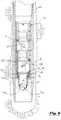
- FIG. 1depicts a side sectional view of "auto-fill" type float assembly 100 of the present invention installed within a wellbore 320 which extends into the earth's crust.
- float assembly 100is installed near the bottom (distal) end of casing string 300 which has a central flow bore 301.
- float assembly 100 of the present inventionpermits cement slurry to flow down central flow bore 301 and out the open distal end 302 of casing 300 and into annular space 321 formed between wellbore 320 and the external surface of casing 300.
- Float assembly 100permits cement slurry to flow out of distal end 302 of casing 300, while preventing back-flow of such heavy cement slurry into central flow bore 301 of casing 300 when pumping ceases. Without float assembly 100, the relatively heavy cement slurry pumped into annular space 321 can "U-tube” or reverse flow back into central flow bore 301 of casing 300.
- float assembly 100 of the present inventioncan be run into wellbore 320 on casing string 300 in an open position, such that wellbore fluids can pass bi-directionally through said float collar assembly 100. Because of the large, unrestricted internal diameter of said float collar assembly 100 when said assembly 100 is in said open position, higher auto-filling flow rates and maximum debris tolerance through said float assembly 100 are achieved. Accordingly, because float assembly 100 of the present invention does not exhibit the same restrictions as conventional float assemblies, less fluid surge pressure is exerted on wellbore 320 and any potentially-sensitive formations present in said wellbore 320 when a casing string equipped with float assembly 100 is lowered into said wellbore.
- said float assembly 100generally comprises ball retaining sub 10, upper valve assembly 20, upper spacer member 30, lower valve assembly 40, lower spacer member 50, collar member 60, moveable ball seat member 70, retaining sleeve 80 and bottom housing 90.
- ball retaining sub 10is connected to upper valve assembly 20, which is in turn connected to upper spacer member 30.
- Lower valve assembly 40is connected below upper spacer member 30, while lower spacer member 50 is connected below said lower valve assembly 40.
- Collar member 60is slidably received around the outer surface of ball seat member 70.
- Ball seat member 70is slidably disposed within retaining sleeve 80 and bottom housing 90.
- Each of the aforementioned elementscontain a central flow bore; said flow bores are aligned and collectively form a central flow bore extending substantially through said float assembly 100 along its longitudinal axis.
- retaining sub 10, upper valve assembly 20, upper spacer member 30, lower valve assembly 40, lower spacer member 50, and bottom housing 90are concentrically disposed within external sleeve member 5; all of said components are received within casing string 300 near distal end 302.
- ball retaining sub 10, upper valve assembly 20, upper spacer member 30, lower valve assembly 40, lower spacer member 50, collar member 60, ball seat member 70, retaining sleeve 80 and bottom housing 90are beneficially modular in design, such that any of said components can be quickly and easily removed from said assembly, and repaired and/or replaced, thereby allowing for greater operational flexibility.
- float assembly 100 of the present inventioncomprises at least two curved, composite flapper-style valve assemblies; in the embodiment depicted in FIG. 1 , upper valve assembly 20 has upper flapper 120, while lower valve assembly 40 has lower flapper 140.
- Each of said flappers 120 and 140 of the present inventionhave a range of motion of approximately 90°, and each are biased in a closed position using a torsion spring as set forth in greater detail below.
- said flappers 120 and 140are mounted with 180 degree phasing relative to one another; put another way, one flapper is pivotally mounted to open against one side of float assembly 100, while the other flapper is pivotally mounted to open against an opposing side (that is, 180 degrees offset) of said float assembly 100.
- flappers 120 and 140At least one flapper will always be on the lower side of wellbore 320 when float assembly 100 of the present invention is used in a deviated well.
- the configuration of the present inventionpermits independent pressure testing of the valve assemblies of the present invention, which provides significant safety improvement over existing prior art float assemblies.
- actuation ball 110is disposed within ball retaining sub 10.
- actuation ball 110is constructed of low-density material (such as, for example, a phenolic material), which permits said actuation ball 110 to float in wellbore fluids, thus keeping said ball 110 from falling through the tool and prematurely actuating float assembly 100 when such actuation is not desired. Further, said actuating ball 110 is prevented from floating out of float assembly 100 and is held within ball retaining sub 10 using optional removable ball retaining pin 11.
- actuating ball 110 of the present inventionremains positioned offset from the center of said central flow bore of ball retaining sub 10 using retaining pin 11. As a result of this positioning of actuating ball 110, a larger area of the central flow bore of ball retaining sub 10 (and float assembly 100) remains unobstructed, thereby permitting larger solids and/or debris to flow past said ball 110 than conventional prior art assemblies 100.
- FIG. 2depicts a detailed view of highlighted area "2" of float assembly 100 of the present invention depicted in FIG. 1 .
- Upper valve assembly 20comprises upper valve housing 21 having central flow bore 22 extending therethrough.
- Upper valve assembly 20is concentrically disposed within external sleeve 5, which is in turn concentrically disposed within central bore 301 of casing string 300.
- Upper flapper 120is pivotally connected to upper valve housing 21 using upper hinge pin 23.
- Torsion spring 24acts to bias upper flapper 120 toward the closed position (that is, a position in which flapper 120 rotates about upper hinge pin 23 and seals central flow bore 22 of upper valve housing 21 against upward fluid pressure from below by engaging against upper valve seat 25).
- FIG. 1depicts a detailed view of highlighted area "2" of float assembly 100 of the present invention depicted in FIG. 1 .
- Upper valve assembly 20comprises upper valve housing 21 having central flow bore 22 extending therethrough.
- Upper valve assembly 20is concentrically disposed within external sleeve 5, which
- upper locking rod 130is slidably received within a recess 121 in upper flapper 120.
- Said upper locking rod 130acts to resist the forces applied to upper flapper 120 by torsion spring 24, and thereby prevents upper flapper 120 from rotating about upper hinge pin 23 and moving into central flow bore 22 of upper valve housing 21.
- upper flapper 120is held in an open position against a side wall of upper spacer member 30.
- FIG. 3depicts a detailed view of a highlighted section of float assembly 100 of the present invention depicted in FIG. 1 with lower flapper 140 in the full open position.
- Lower valve assembly 40comprises upper valve housing 41 having central flow bore 42 extending therethrough.
- Lower valve assembly 40is concentrically disposed within external sleeve 5, which is in turn concentrically disposed within casing string 300.
- Lower flapper 140is pivotally connected to lower valve housing 41 using lower hinge pin 43.
- Torsion spring 44acts to bias lower flapper 140 toward the closed position (that is, a position in which flapper 140 rotates about lower hinge pin 43 and seals central flow bore 42 of lower valve housing 41 against upward pressure from below by engaging against lower flapper seat 46).
- FIG. 1depicts a detailed view of a highlighted section of float assembly 100 of the present invention depicted in FIG. 1 with lower flapper 140 in the full open position.
- Lower valve assembly 40comprises upper valve housing 41 having central flow bore 42 extending therethrough.
- Lower valve assembly 40is concentrically
- lower locking rod 150is slidably received within recess 141 in lower flapper 140.
- Said lower locking rod 150acts to resist the forces applied to lower flapper 140 by torsion spring 44, and thereby preventing lower flapper 140 from rotating about lower hinge pin 43 and moving into central flow bore 42 of lower valve housing 41. In this position, lower flapper 140 is held in an open position against a side wall of lower spacer member 50.
- lower spacer member 50is connected to the base of lower valve assembly 40, while bottom housing 90 is connected to the base of said lower spacer member 50.
- Bottom housing 90has central bore 91 extending therethrough.
- Retaining sleeve 80, having central bore 81,is connected to bottom housing 90.
- Collar member 60has central bore 61 extending therethrough, and is slidably received within central bore 91 of bottom housing 90.
- Ball seat member 70 having central bore 71is connected to collar member 60, and is concentrically and slidably received within central bore 81 of retaining member 80.
- ball seat member 70is secured against axial movement within central bore 81 of retaining sleeve 80 using at least one shear pin 160.
- Ball seat member 70has a plurality of collets 72 disposed at its lower end. Said collets 72 have dogs 72a that extend into central bore 71 of ball seat member 70, and cooperatively act to form a "seat" by restricting the internal diameter of said central bore 71.
- Upper locking rod 130 and lower locking rod 150are connected to collar member 60 using transverse rod retaining pins 65.
- said rod retaining pins 65extend through aligned transverse bores in collar member 60 and each of said upper and lower locking rods 130 and 150.
- Upper locking rod 130is slidably received within aligned rod bores 45 and 55 of lower valve assembly 40 and lower spacer member 50, respectively.
- Said rod bores 45 and 55are substantially parallel to the longitudinal axes of central flow bore 43 of lower valve assembly 40 and central bore of lower spacer member 50.
- lower locking rod 150The upper end of lower locking rod 150 is slidably received within recess 141 in lower flapper 140. Said lower locking rod 150 acts to resist the forces applied to lower flapper 140 by torsion spring 44, and thereby preventing lower flapper 140 from rotating about lower hinge pin 43 and moving into central flow bore 42 of lower valve housing 41. In this position, lower flapper 140 is held in an open position against a side wall of lower spacer member 50.
- FIG. 4depicts a side sectional view of float assembly 100 of the present invention installed in a wellbore 320 with actuation ball 110 in a seated position on the seat formed by cooperating collet dogs 72a. It is to be observed that floatable actuation ball 110 can be included within float assembly 100 and maintained within ball retaining sub 10 using retaining pin 11 as casing string 300 is run into wellbore 320. Alternatively, float assembly 100 can be run into wellbore 320 without retaining pin 11 and actuation ball 110.
- actuation ball 110can be dropped, launched or otherwise placed into central bore 301 of casing string 300 and pumped downhole into float assembly 100 until it is ultimately received on the seat formed by cooperating collet dogs 72a of collets 72.
- FIG. 5depicts a detailed view of a highlighted area 5 of float assembly 100 of the present invention depicted in FIG. 4 , with actuation ball 110 in a seated position on the seat formed by cooperating collet dogs 72a.
- Ball seat member 70remains secured against axial movement within central bore 81 of retaining sleeve 80 by shear pins 160.
- lower locking rod 150remains received within recess 141 in lower flapper 140, thereby preventing lower flapper 140 from closing. In this position, lower flapper 140 is held in an open position against a side wall of lower spacer member 50.
- upper end of upper locking rod 130is similarly slidably received within recess 121 in upper flapper 120, thereby preventing upper flapper 120 from closing. In this position, upper flapper 120 is also held in an open position against a side wall of upper spacer member 30.
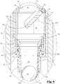
- FIG. 6depicts a side sectional view of float assembly 100 of the present invention installed in wellbore 320 with actuation ball 110 in a seated position on cooperating collet dogs 72a of collets 72.
- fluid pressurehas been applied above actuation ball 110, causing axial (downward) force to act on actuation ball 110 and, in turn, ball seat member 70.
- shear pins 160which are set to a predetermined force shear, thereby permitting axial movement of ball seat member 70 within central bore 81 of retaining sleeve 80.
- FIG. 7depicts a detailed view of a highlighted area 7 of float assembly 100 depicted in FIG. 6 with upper flapper 120 in a partially closed position.
- the upper end of upper locking rod 130has been disengaged from recess 121 in upper flapper 120.
- upper flapper 120is permitted to rotate about upper hinge pin 23 and engage against flapper seat 25 and seal flow bore 22 of upper valve housing 21 against upward pressure from below said flapper 120.
- FIG. 8depicts a detailed view of a highlighted area 8 of float assembly 100 of the present invention depicted in FIG. 6 .
- Actuation ball 110is received and seated on cooperating collet dogs 72a of collets 72. Fluid pressure applied above actuation ball 110 causes axial (downward) force to act on actuation ball 110 and, in turn, ball seat member 70. As such force reaches a desired level, shear pins 160 shear, thereby permitting axial movement of ball seat member 70 within central bore 81 of retaining sleeve 80. Such downward movement of ball seat member 70 causes corresponding downward movement of collar 60 and upper locking rod 130 and lower locking rod 150.
- lower locking rod 150disengages from recess 141 in lower flapper 140. Without said lower locking rod 150 acting to resist the forces applied to lower flapper 140 by torsion spring 44, lower flapper 140 is permitted to rotate about lower hinge pin 43 and engage against lower flapper seat 46 to seal central flow bore 42 of lower valve housing 41.
- FIG. 9depicts a side sectional view of float assembly 100 of the present invention installed in wellbore 320.
- Fluid pressurehas been applied above actuation ball 110, causing axial (downward) force to act on actuation ball 110 and, in turn, ball seat member 70.
- downward movement of ball seat member 70causes corresponding downward movement of collar 60 which, in turn, translates to downward movement of upper locking rod 130 and lower locking rod 150 (each of which are connected to collar member 60 using rod retaining pins 65).
- collets 72spread apart radially outward, thereby permitting actuation ball 110 to be expelled out the bottom of ball seat member 70.
- upper flapper 120is permitted to rotate about upper hinge pin 23, ultimately engaging and sealing against upper flapper 25 and sealing central flow bore 22 of upper valve housing 21 against upward pressure from below.
- lower flapper 140is permitted to rotate about lower hinge pin 43, ultimately sealing against lower flapper seat 46 and sealing central flow bore 42 of lower valve housing 41 against upward pressure from below.
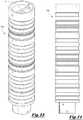
- FIG. 12depicts an exploded perspective view of float assembly 100 of the present invention comprising ball retaining sub 10, upper valve assembly 20, upper spacer member 30, lower valve assembly 40, lower spacer member 50, collar member 60, ball seat member 70, retaining sleeve 80 and bottom housing 90.
- Ball retaining sub 10has central bore 12 extending through said sub, as well as aligned transverse bores 13 extending through the side walls of ball retaining sub 10. Transverse bores 13 are aligned with each other and oriented substantially perpendicular to the longitudinal axis of central bore 12. After actuation ball 110 is installed in central bore 12, retaining pin 11 can be installed in said transverse bores 13. Said retaining pin 11 will prevent floatable actuation ball 110 from floating out of float assembly 100 as said assembly is being lowered into a wellbore.
- Sealing ring 14can be installed between ball retaining sub 10 and upper valve assembly; in the preferred embodiment, said sealing ring 14 can be made of rubber or other elastomeric sealing material.
- Upper valve assembly 20comprises upper valve housing 21 having central flow bore 22 extending therethrough.
- Upper flapper 120is pivotally connected to upper valve housing 21 using upper hinge pin 23.
- Torsion spring 24acts to bias upper flapper 120 toward the closed position (that is, a position in which flapper 120 rotates about upper hinge pin 23 and seals central flow bore 22 of upper valve housing 21).
- Upper flapper sealing element 122can form a fluid pressure seal when flapper 120 is closed, and can be made of rubber or other elastomeric sealing material
- Upper spacer member 30 having central bore 31is situated below upper valve assembly 20. When upper flapper 120 is in the open position, said upper flapper 120 extends into central bore 31 of upper spacer member 30.
- Lower valve assembly 40connected beneath upper spacer member 30, comprises lower valve housing 41 having central flow bore 42 extending therethrough.
- Lower flapper 140is pivotally connected to lower valve housing 41 using lower hinge pin 43.
- Torsion spring 44acts to bias lower flapper 140 toward the closed position (that is, a position in which flapper 140 rotates about lower hinge pin 43 and seals central flow bore 42 of lower valve housing 41).
- Lower flapper sealing element 142can form a fluid pressure seal when flapper 140 is closed, and can be made of rubber or other elastomeric sealing material
- Lower spacer member 50 having central bore 51is situated below lower valve assembly 40. When lower flapper 140 is in the open position, said lower flapper 140 extends into central bore 51 of lower spacer member 50.
- Bottom housing 90has central bore 91 extending therethrough.
- Retaining sleeve 80, having central bore 81,is connected to bottom housing 90.
- Collar member 60has central bore 61 extending therethrough, and is slidably received within central bore 91 of bottom housing 90.
- Ball seat member 70 having central bore 71is connected to collar member 60, and is concentrically and slidably received within central bore 81 of retaining member 80.
- Ball seat member 70is secured against axial movement within central bore 81 of retaining sleeve 80 using shear pins 160.
- Ball seat member 70has a plurality of collets 72 disposed at its lower end. Said collets 72 have cooperating dogs 72a that extend into central bore 71 of ball seat member 70, and cooperatively act to form a "seat" by restricting the internal diameter of said central bore 71.
- Upper locking rod 130has transverse bore 131, while lower locking rod 150 has transverse bore 151.
- said rod retaining pins 65extend through aligned transverse bores in collar member 60, as well as aligned bores 131 and 151 of said upper and lower locking rods 130 and 150, respectively.
- upper locking rod 130is slidably received within aligned rod bores 45 and 55 of lower valve assembly 40 and lower spacer member 50, respectively.
- Said rod bores 45 and 55are oriented substantially parallel to the longitudinal axes of central flow bore 43 of lower valve assembly 40 and central bore of lower spacer member 50.
- FIG. 13depicts a perspective view of assembled float assembly 100 of the present invention
- FIG. 14depicts a side view of said assembled float assembly 100 of the present invention
- float assembly 100is concentrically disposed within an external sleeve member (such as external sleeve member 5 in FIG. 1 , not shown in FIG. 14 ).
- Said external sleeve 5, together with float assembly 100,is received within a casing string (such as casing string 300 in FIG. 1 ).
- FIG. 15depicts a perspective view of upper valve assembly 20 of the present invention with flapper 120 in a fully open position.
- upper valve housing 21 and flapper 120are manufactured from high-temperature resins compression molded around a carbon- or glass-reinforced framework for added strength.
- Valve housing 21also has spring slot 26 for receiving torsion spring 24.
- Flapper 120has end recess 121, as well as a curved profile with concave sealing surface 123 and convex back surface 124.
- FIG. 16depicts a perspective view of upper valve assembly 20 of the present invention with flapper 120 in a fully closed position.
- FIG. 17depicts an end view of upper valve assembly 20 of the present invention with flapper 120 in a fully open position.
- the curved shape of flapper 120 (and 140)allows the largest-possible inner diameter (ID) to be maintained when valve assemblies 20 and 40 are in the open position (that is, when flappers 120 and 140 are open), resulting in higher auto-filling flow rates and maximum debris tolerance through the central bore of float assembly 100. Additionally, the curved design of flappers 120 and 140 yield significantly higher pressure ratings for the valves of the present invention compared to prior art valve assemblies.
- FIG. 18depicts a side perspective view of collar member 60 of the present invention.
- Collar member 60has a plurality of transverse bores 62 for receiving rod retaining pins 65, as well as inner shoulder 63 and inner dogs 64.
- Collar member 60can also have a sealing member 66 around its outer circumference.
- FIG. 19depicts a side perspective view of ball seat member 70 of the present invention.
- Ball seat member 70is generally cylindrical in shape, and has a plurality of collets 72 disposed at its lower end. Said collets 72 have dogs 72a that extend into central bore 71 of ball seat member 70, and cooperatively act to form a "seat" by restricting the internal diameter of said central bore 71.
- Ball seat member 70also has a plurality of transverse bores 73 for receiving shear pins 160, as well upper shoulder 74 and dogs 75 extending radially outward from said ball seat member 70.
- FIG. 20depicts a side perspective view of retaining sleeve member 80 of the present invention.
- Retaining sleeve memberhas central bore 81, dogs 82 extending radially outward, and a plurality of transverse bores 83 extending through said retaining sleeve member 80 for receiving shear pins 160.
- FIG. 21depicts a side perspective view of bottom housing 90 of the present invention.
- Bottom housing 90is substantially cylindrical and has central bore 91 and inner dogs 92.
- valves of float assembly 100are selectively actuated using a floatable actuation ball 110 (by way of illustration, but not limitation, constructed of phenolic material) that can beneficially engage against a corresponding colletted ball seat formed by cooperating collet dogs 72a positioned below said valves.
- a floatable actuation ball 110by way of illustration, but not limitation, constructed of phenolic material
- said actuation ballis received on said seat, forming a substantially complete flow restriction through central flow bore of said float assembly 100.
- fluid pressurecan then be increased above said seated ball 110.
- sufficient forcewill act upon at least one composite shear pin causing such pin to shear, thereby allowing ball seat member 70 to shift downward, away from the valves.
- Such shiftingactuates the mechanism holding flappers 120 and 140 open, thereby allowing said flappers to close.
- collets 72 of ball seat member 70spread radially apart, allowing actuation ball 110 to pass through said opened collets 72 and to be expelled from float assembly 100 into wellbore 320 below.
- the colletted ball seat of the present inventionpermits changing of both the number of composite shear pins (thereby permitting adjustment of the activation pressure) and flow port size (thereby permitting adjustment of the activation flow rate) of the system.
- flappers 120 and 140are manufactured from high-temperature resins compression molded around a carbon- or glass-reinforced framework for added strength.
- the curved profile of said flappersallows the largest-possible inner diameter (ID) to be maintained when the valves are in the open position; such lack of restriction results in higher auto-filling flow rates and maximum debris tolerance through the central bore of said float assembly.
- IDinner diameter
- the configuration of valve mechanismsincluding, without limitation the shape of curved flappers 120 and 140, yield significantly higher pressure ratings for the valves of the present invention compared to valves of existing prior art assemblies.
- valve springs 24 and 44are carbon- or glass-reinforced single torsion-type springs.
- Hinge pins 23 and 43, as well as other activation mechanism components,are comprised of carbon- or glass-reinforced rods for high tensile and shear strength.
- Colletted ball seat member 70is also manufactured as a high-temperature mandrel-wrapped reinforced composite.
- Shear pins 160are ultrafine-grain graphite or uniform-resin composite, which are not affected by temperature like conventional metallic shear pins.
- Actuation ball 110is beneficially constructed from a low-density phenolic material, which floats in most wellbore fluids, keeping the ball away from ball seat member 70 until desired, thereby reducing the likelihood of packing-off the central flow bore of the assembly with cuttings or other wellbore debris.
Landscapes
- Engineering & Computer Science (AREA)
- Geology (AREA)
- Life Sciences & Earth Sciences (AREA)
- Mining & Mineral Resources (AREA)
- Environmental & Geological Engineering (AREA)
- Fluid Mechanics (AREA)
- Physics & Mathematics (AREA)
- General Life Sciences & Earth Sciences (AREA)
- Geochemistry & Mineralogy (AREA)
- Mechanical Engineering (AREA)
- Float Valves (AREA)
- Check Valves (AREA)
- Taps Or Cocks (AREA)
Description
- The present invention pertains to a large bore float assembly. More particularly, the present invention pertains to a large bore float assembly having at least one flapper valve. More particularly still, the present invention pertains to a float assembly having non-metallic valves and other components, yet providing a greater pressure rating than conventional float assemblies.
- Drilling of an oil or gas well is frequently accomplished using a surface drilling rig and tubular drill pipe. When installing drill pipe (or other tubular goods) into a well, such pipe is typically inserted into a wellbore in a number of sections of roughly equal length called "joints". As the pipe penetrates deeper into a well, additional joints of pipe must be added to the ever lengthening "drill string" at the drilling rig. As such, a typical drill string comprises a plurality of sections or joints of pipe, each of which has an internal, longitudinally extending bore.
- After a well is drilled to a desired depth, relatively large diameter pipe known as casing is typically installed and cemented in place within the wellbore. Cementing is performed by pumping a predetermined volume of cement slurry into the well using high-pressure pumps. The cement slurry is typically pumped down the inner bore of the casing, out the distal end of the casing, and back up around the outer surface of the casing. After the predetermined volume of cement is pumped, a plug or wiper assembly is typically pumped down the inner bore of the casing using drilling mud or other fluid in order to fully displace the cement from the inner bore of the casing. In this manner, the cement slurry leaves the inner bore of the casing and enters the annular space existing between the outer surface of the casing and the inner surface of the wellbore. As such cement hardens, it should beneficially secure the casing in place and form a seal to prevent fluid flow along the outer surface of the casing.
- In many conventional cementing operations, an apparatus known as a float collar or float assembly is frequently utilized at or near the bottom (distal) end of the casing string. In most cases, the float assembly comprises a short length of casing or other tubular housing fitted with a check valve assembly, such as a flapper-valve, spring-loaded ball valve or other type of closing mechanism. The check-valve assembly permits the cement slurry to flow out the distal end of the casing, but prevents back-flow of the heavier cement slurry into the inner bore of the casing when pumping stops. Without such a float collar, the heavy cement slurry pumped into the annular space around the outside of the casing can U-tube or reverse flow back into the inner bore of the casing, which can result in a very undesirable situation.
- Auto-fill float systems comprise specialized float collar assemblies that have been long known and widely used in the oil and gas industry. Generally, auto-fill float systems consist of float assemblies with one or more flapper-style valves run into a wellbore in an open position, such that wellbore fluids can flow bi-directionally through the assembly. When desired, said valves can be selectively closed via actuation mechanism(s); such activation mechanisms can include, for example, pressure and/or flow rate increases through the casing string. One common actuation mechanism involves insertion of a tubular member or sleeve through the valve body(ies) in order to hold the flapper(s) open. When desired, the tubular member can be selectively expelled from the assembly via a drop ball or other item; with the sleeve out of the way, the valve(s) are permitted to close.
US 3,292,707 describes a release mechanism for a well device comprising a releasably held segment maintaining a back-check valve in an inactive position and means associated with said segment for releasing the segment and thereby allowing the back-check valve to become active.- As with virtually any float assembly, after cement slurry has been pumped and set, the float assembly must frequently be drilled out, typically with a PDC or roller-cone type bit. As such, the need for constructing float collar assemblies from drillable materials - such as composite material - is paramount. While composite valve bodies and flappers have existed for some time, both ferrous and non-ferrous metallic components continue to be used in the form of shear pins, hinge pins, and valve springs. Additionally, existing auto-fill systems have limited to no capability to adjust the activation variables such as, for example, deactivation pressure and/or flow rate. Such considerations highlight the need for improvement over existing prior out float assemblies.
- Further, although float assemblies have been known in the art for some time, many have relatively small internal flow bores. As a result, pieces of rock or debris including, without limitation, debris suspended within the cement slurry can become lodged in the inner bore of the float assembly, thereby impeding progress of cementing operations and creating an unsafe condition. Further, problems exist with many existing prior art float valve assemblies, in terms of both actuation and the ability to withstand pressure loading.
- Thus, there is a need for a durable, easily drillable, large-bore float assembly having at least one reliable, high-pressure valve assembly that can withstand significant wellbore pressures.
- In the preferred embodiment, the present invention comprises an "auto-fill" type float assembly having at least one composite, curved flapper valve for auto-filling a casing or liner string during oil and gas tubular running and cementing operations.
- Considered broadly, the present invention comprises an auto-fill type float assembly having a central flow bore extending longitudinally therethrough. The float assembly of the present invention compromises two or more curved composite flapper-style valves. Each of said flappers of the present invention have a substantially 90° range of motion, and are closed via a torsion spring. Although said torsion spring can have many different embodiments, in the preferred embodiment said spring is made of composite material and is disposed around the circumference of the valve body. Each flapper is connected to the valve body via a composite hinge pin. Said flappers are held in the open (or "auto-fill"), position via an external shifting mechanism that does not require any obstruction or restriction through the central flow bore of any valve assembly.
- In the preferred embodiment, the valve mechanism of the present invention is selectively actuated using a floatable ball (such as, for example, a ball constructed of phenolic material) that can beneficially engage against a corresponding ball seat member positioned below said valves. When flow rate is established through the system, the ball is pumped downward and becomes seated on said seat member forming a flow restriction within the central flow bore of said assembly.
- Fluid pressure can then be increased above said seated ball. At a predetermined, specified pressure, at least one composite pin will shear, thereby allowing said ball seat member to shift downward, away from the valves. This event actuates the mechanism holding the flappers open, thereby allowing said valves to close. As pressure continues to increase above the ball, the collets of the ball seat member spread apart, allowing the ball to pass through said opened collets, and be expelled from the assembly into the wellbore below thereby removing the restriction from the central flow bore of the assembly. The colletted ball seat member permits changing of both the number of composite shear pins (thereby permitting adjustment of the activation pressure) and flow port size (thereby permitting adjustment of the activation flow rate) of the system.
- According to one particularly advantageous embodiment of the present invention, the flapper and valve bodies are manufactured from high-temperature resins compression molded around a carbon- or glass-reinforced framework for added strength. The curved profile of each flapper allows the largest-possible inner diameter (ID) to be maintained when the valve is in the open position, resulting in higher auto-fill flow rates and maximum debris tolerance through the central flow bore of the assembly.
- In the preferred embodiment, the valve springs of the present invention comprise carbon- or glass-reinforced single torsion-type springs. The hinge pins and deactivation mechanism components are beneficially manufactured of carbon- or glass-reinforced rods for high tensile and shear strength. The colletted ball seat is manufactured as a high-temperature mandrel-wrapped reinforced composite. The shear pins are ultrafine-grain graphite or uniform-resin composite. The drop ball is a low-density phenolic, which floats in most wellbore fluids, keeping the ball away from the ball seat until activation is required thereby reducing the likelihood of packing-off the central flow bore of the assembly with cuttings or other wellbore debris. The system further incorporates a ball retainer which can be removed to allow the ball to be dropped or to float in the casing/liner as needed.
- The foregoing summary, as well as the following detailed description of the preferred embodiments, is better understood when read in conjunction with the appended drawings. For the purpose of illustrating the invention, the drawings show certain preferred embodiments. It is understood, however, that the invention is not limited to the specific methods and devices disclosed. Further, dimensions, materials and part names are provided for illustration purposes only and not limitation.
FIG. 1 depicts a side sectional view of the float assembly of the present invention installed in a wellbore with two flapper valves in a fully opened position.FIG. 2 depicts a detailed view of a highlighted section of the float assembly of the present invention depicted inFIG. 1 with the upper flapper in the full open position.FIG. 3 depicts a detailed view of a highlighted section of the float assembly of the present invention depicted inFIG. 1 with the lower flapper in the full open position.FIG. 4 depicts a side sectional view of the float assembly of the present invention installed in a wellbore with an actuation ball in a seated position and the valves of the present invention in an open position.FIG. 5 depicts a detailed view of a highlighted section of the float assembly of the present invention depicted inFIG. 4 with an actuation ball in a seated position and the lower valve of the present invention in an open position.FIG. 6 depicts a side sectional view of the float assembly of the present invention installed in a wellbore with an actuation ball in a seated position and two flapper valves in a partially closed position.FIG. 7 depicts a detailed view of a highlighted section of the float assembly of the present invention depicted inFIG. 6 with the upper flapper in a partially closed position.FIG. 8 depicts a detailed view of a highlighted section of the float assembly of the present invention depicted inFIG. 6 with an actuation ball in a seated position and the lower valve of the present invention in a partially closed position.FIG. 9 depicts a side sectional view of the float assembly of the present invention installed in a wellbore with two flapper valves in a fully closed position.FIG. 10 depicts a detailed view of a highlighted section of the float assembly of the present invention depicted inFIG. 9 with the upper flapper in a fully closed position.FIG. 11 depicts a detailed view of a highlighted section of the float assembly of the present invention depicted inFIG. 9 with the lower flapper in a fully closed position.FIG. 12 depicts an exploded perspective view of the float assembly of the present invention.FIG. 13 depicts a perspective view of the float assembly of the present invention.FIG. 14 depicts a side view of a float assembly of the present invention.FIG. 15 depicts a perspective view of a valve assembly of the present invention in an open position.FIG. 16 depicts a perspective view of a valve assembly of the present invention in a closed positionFIG. 17 depicts an end view of a valve assembly of the present invention with a flapper in an open position.FIG. 18 depicts a perspective view of a collar member of the present invention.FIG. 19 depicts a perspective view of a ball seat member of the present invention.FIG. 20 depicts a perspective view of a retaining sleeve of the present invention.FIG. 21 depicts a perspective view of a bottom housing of the present invention.FIG. 1 depicts a side sectional view of "auto-fill"type float assembly 100 of the present invention installed within awellbore 320 which extends into the earth's crust. As depicted inFIG. 1 ,float assembly 100 is installed near the bottom (distal) end ofcasing string 300 which has a central flow bore 301. Generally,float assembly 100 of the present invention permits cement slurry to flow down central flow bore 301 and out the opendistal end 302 ofcasing 300 and intoannular space 321 formed betweenwellbore 320 and the external surface ofcasing 300.Float assembly 100 permits cement slurry to flow out ofdistal end 302 ofcasing 300, while preventing back-flow of such heavy cement slurry into central flow bore 301 ofcasing 300 when pumping ceases. Withoutfloat assembly 100, the relatively heavy cement slurry pumped intoannular space 321 can "U-tube" or reverse flow back into central flow bore 301 ofcasing 300.- As set forth in greater detail below,
float assembly 100 of the present invention can be run intowellbore 320 oncasing string 300 in an open position, such that wellbore fluids can pass bi-directionally through saidfloat collar assembly 100. Because of the large, unrestricted internal diameter of saidfloat collar assembly 100 when saidassembly 100 is in said open position, higher auto-filling flow rates and maximum debris tolerance through saidfloat assembly 100 are achieved. Accordingly, becausefloat assembly 100 of the present invention does not exhibit the same restrictions as conventional float assemblies, less fluid surge pressure is exerted onwellbore 320 and any potentially-sensitive formations present in saidwellbore 320 when a casing string equipped withfloat assembly 100 is lowered into said wellbore. - Referring briefly to
FIG. 12 , which depicts an exploded view offloat assembly 100, saidfloat assembly 100 generally comprisesball retaining sub 10,upper valve assembly 20,upper spacer member 30,lower valve assembly 40,lower spacer member 50,collar member 60, moveableball seat member 70, retainingsleeve 80 andbottom housing 90. - Referring back to
FIG. 1 ,ball retaining sub 10 is connected toupper valve assembly 20, which is in turn connected toupper spacer member 30.Lower valve assembly 40 is connected belowupper spacer member 30, whilelower spacer member 50 is connected below saidlower valve assembly 40.Collar member 60 is slidably received around the outer surface ofball seat member 70.Ball seat member 70 is slidably disposed within retainingsleeve 80 andbottom housing 90. Each of the aforementioned elements contain a central flow bore; said flow bores are aligned and collectively form a central flow bore extending substantially through saidfloat assembly 100 along its longitudinal axis. - In the preferred embodiment of the present invention, retaining
sub 10,upper valve assembly 20,upper spacer member 30,lower valve assembly 40,lower spacer member 50, andbottom housing 90 are concentrically disposed withinexternal sleeve member 5; all of said components are received withincasing string 300 neardistal end 302. Further,ball retaining sub 10,upper valve assembly 20,upper spacer member 30,lower valve assembly 40,lower spacer member 50,collar member 60,ball seat member 70, retainingsleeve 80 andbottom housing 90 are beneficially modular in design, such that any of said components can be quickly and easily removed from said assembly, and repaired and/or replaced, thereby allowing for greater operational flexibility. - Still referring to
FIG. 1 ,float assembly 100 of the present invention comprises at least two curved, composite flapper-style valve assemblies; in the embodiment depicted inFIG. 1 ,upper valve assembly 20 hasupper flapper 120, whilelower valve assembly 40 haslower flapper 140. Each of saidflappers flappers float assembly 100, while the other flapper is pivotally mounted to open against an opposing side (that is, 180 degrees offset) of saidfloat assembly 100. - As a result of this configuration of
flappers wellbore 320 whenfloat assembly 100 of the present invention is used in a deviated well. Further, the configuration of the present invention permits independent pressure testing of the valve assemblies of the present invention, which provides significant safety improvement over existing prior art float assemblies. - As depicted in
FIG. 1 ,actuation ball 110 is disposed withinball retaining sub 10. In the preferred embodiment,actuation ball 110 is constructed of low-density material (such as, for example, a phenolic material), which permits saidactuation ball 110 to float in wellbore fluids, thus keeping saidball 110 from falling through the tool and prematurely actuatingfloat assembly 100 when such actuation is not desired. Further, saidactuating ball 110 is prevented from floating out offloat assembly 100 and is held withinball retaining sub 10 using optional removableball retaining pin 11. - Conventional float collar assemblies typically employ an actuating ball that is retained in a substantially central location within the flow bore of each such assembly. However, positioning an actuation ball in this manner significantly restricts the cross-sectional flow area through a float assembly and, as a result, the ability of solids or other larger materials to pass through said central flow bore. By contrast, actuating
ball 110 of the present invention remains positioned offset from the center of said central flow bore ofball retaining sub 10 using retainingpin 11. As a result of this positioning ofactuating ball 110, a larger area of the central flow bore of ball retaining sub 10 (and float assembly 100) remains unobstructed, thereby permitting larger solids and/or debris to flow past saidball 110 than conventionalprior art assemblies 100. FIG. 2 depicts a detailed view of highlighted area "2" offloat assembly 100 of the present invention depicted inFIG. 1 .Upper valve assembly 20 comprisesupper valve housing 21 having central flow bore 22 extending therethrough.Upper valve assembly 20 is concentrically disposed withinexternal sleeve 5, which is in turn concentrically disposed withincentral bore 301 ofcasing string 300.Upper flapper 120 is pivotally connected toupper valve housing 21 usingupper hinge pin 23.Torsion spring 24 acts to biasupper flapper 120 toward the closed position (that is, a position in which flapper 120 rotates aboutupper hinge pin 23 and seals central flow bore 22 ofupper valve housing 21 against upward fluid pressure from below by engaging against upper valve seat 25). However, as depicted inFIG. 2 ,upper locking rod 130 is slidably received within arecess 121 inupper flapper 120. Saidupper locking rod 130 acts to resist the forces applied toupper flapper 120 bytorsion spring 24, and thereby preventsupper flapper 120 from rotating aboutupper hinge pin 23 and moving into central flow bore 22 ofupper valve housing 21. As depicted inFIG. 2 , in this positionupper flapper 120 is held in an open position against a side wall ofupper spacer member 30.FIG. 3 depicts a detailed view of a highlighted section offloat assembly 100 of the present invention depicted inFIG. 1 withlower flapper 140 in the full open position.Lower valve assembly 40 comprisesupper valve housing 41 having central flow bore 42 extending therethrough.Lower valve assembly 40 is concentrically disposed withinexternal sleeve 5, which is in turn concentrically disposed withincasing string 300.Lower flapper 140 is pivotally connected tolower valve housing 41 usinglower hinge pin 43.Torsion spring 44 acts to biaslower flapper 140 toward the closed position (that is, a position in which flapper 140 rotates aboutlower hinge pin 43 and seals central flow bore 42 oflower valve housing 41 against upward pressure from below by engaging against lower flapper seat 46). However, as depicted inFIG. 3 ,lower locking rod 150 is slidably received withinrecess 141 inlower flapper 140. Saidlower locking rod 150 acts to resist the forces applied tolower flapper 140 bytorsion spring 44, and thereby preventinglower flapper 140 from rotating aboutlower hinge pin 43 and moving into central flow bore 42 oflower valve housing 41. In this position,lower flapper 140 is held in an open position against a side wall oflower spacer member 50.- Still referring
FIG. 3 ,lower spacer member 50 is connected to the base oflower valve assembly 40, whilebottom housing 90 is connected to the base of saidlower spacer member 50.Bottom housing 90 hascentral bore 91 extending therethrough. Retainingsleeve 80, havingcentral bore 81, is connected tobottom housing 90.Collar member 60 hascentral bore 61 extending therethrough, and is slidably received withincentral bore 91 ofbottom housing 90.Ball seat member 70 havingcentral bore 71 is connected tocollar member 60, and is concentrically and slidably received withincentral bore 81 of retainingmember 80. - As shown in the configuration depicted in
FIG. 3 ,ball seat member 70 is secured against axial movement withincentral bore 81 of retainingsleeve 80 using at least oneshear pin 160.Ball seat member 70 has a plurality ofcollets 72 disposed at its lower end. Saidcollets 72 havedogs 72a that extend intocentral bore 71 ofball seat member 70, and cooperatively act to form a "seat" by restricting the internal diameter of saidcentral bore 71. Upper locking rod 130 andlower locking rod 150 are connected tocollar member 60 using transverse rod retaining pins 65. In the preferred embodiment, said rod retaining pins 65 extend through aligned transverse bores incollar member 60 and each of said upper andlower locking rods Upper locking rod 130 is slidably received within aligned rod bores 45 and 55 oflower valve assembly 40 andlower spacer member 50, respectively. Said rod bores 45 and 55 are substantially parallel to the longitudinal axes of central flow bore 43 oflower valve assembly 40 and central bore oflower spacer member 50.- The upper end of
lower locking rod 150 is slidably received withinrecess 141 inlower flapper 140. Saidlower locking rod 150 acts to resist the forces applied tolower flapper 140 bytorsion spring 44, and thereby preventinglower flapper 140 from rotating aboutlower hinge pin 43 and moving into central flow bore 42 oflower valve housing 41. In this position,lower flapper 140 is held in an open position against a side wall oflower spacer member 50. FIG. 4 depicts a side sectional view offloat assembly 100 of the present invention installed in awellbore 320 withactuation ball 110 in a seated position on the seat formed by cooperatingcollet dogs 72a. It is to be observed thatfloatable actuation ball 110 can be included withinfloat assembly 100 and maintained withinball retaining sub 10 using retainingpin 11 ascasing string 300 is run intowellbore 320. Alternatively,float assembly 100 can be run intowellbore 320 without retainingpin 11 andactuation ball 110. Oncecasing string 300 and floatassembly 100 are at a desired position withinwellbore 320,actuation ball 110 can be dropped, launched or otherwise placed intocentral bore 301 ofcasing string 300 and pumped downhole intofloat assembly 100 until it is ultimately received on the seat formed by cooperatingcollet dogs 72a ofcollets 72.FIG. 5 depicts a detailed view of a highlightedarea 5 offloat assembly 100 of the present invention depicted inFIG. 4 , withactuation ball 110 in a seated position on the seat formed by cooperatingcollet dogs 72a.Ball seat member 70 remains secured against axial movement withincentral bore 81 of retainingsleeve 80 by shear pins 160. As such,lower locking rod 150 remains received withinrecess 141 inlower flapper 140, thereby preventinglower flapper 140 from closing. In this position,lower flapper 140 is held in an open position against a side wall oflower spacer member 50. Although not shown inFIG. 5 , the upper end ofupper locking rod 130 is similarly slidably received withinrecess 121 inupper flapper 120, thereby preventingupper flapper 120 from closing. In this position,upper flapper 120 is also held in an open position against a side wall ofupper spacer member 30.FIG. 6 depicts a side sectional view offloat assembly 100 of the present invention installed inwellbore 320 withactuation ball 110 in a seated position on cooperatingcollet dogs 72a ofcollets 72. As shown in the configuration depicted inFIG. 6 , fluid pressure has been applied aboveactuation ball 110, causing axial (downward) force to act onactuation ball 110 and, in turn,ball seat member 70. As such force reaches a desired level, shear pins 160 (which are set to a predetermined force) shear, thereby permitting axial movement ofball seat member 70 withincentral bore 81 of retainingsleeve 80.- Downward movement of
ball seat member 70 causes corresponding downward movement ofcollar 60 which, in turn, translates to downward movement ofupper locking rod 130 and lower locking rod 150 (each of which are connected to saidcollar member 60 using rod retaining pins 65). As a result of such downward movement, the upper end oflower locking rod 150 disengages fromrecess 141 inlower flapper 140 while the upper end ofupper locking rod 130 disengages fromrecess 121 inupper flapper 120. FIG. 7 depicts a detailed view of a highlightedarea 7 offloat assembly 100 depicted inFIG. 6 withupper flapper 120 in a partially closed position. As depicted inFIG. 7 , the upper end ofupper locking rod 130 has been disengaged fromrecess 121 inupper flapper 120. Without saidupper locking rod 130 acting to resist the forces applied toupper flapper 120 bytorsion spring 24,upper flapper 120 is permitted to rotate aboutupper hinge pin 23 and engage againstflapper seat 25 and seal flow bore 22 ofupper valve housing 21 against upward pressure from below saidflapper 120.FIG. 8 depicts a detailed view of a highlightedarea 8 offloat assembly 100 of the present invention depicted inFIG. 6 .Actuation ball 110 is received and seated on cooperatingcollet dogs 72a ofcollets 72. Fluid pressure applied aboveactuation ball 110 causes axial (downward) force to act onactuation ball 110 and, in turn,ball seat member 70. As such force reaches a desired level, shear pins 160 shear, thereby permitting axial movement ofball seat member 70 withincentral bore 81 of retainingsleeve 80. Such downward movement ofball seat member 70 causes corresponding downward movement ofcollar 60 andupper locking rod 130 andlower locking rod 150. As a result of such downward movement, the upper end oflower locking rod 150 disengages fromrecess 141 inlower flapper 140. Without saidlower locking rod 150 acting to resist the forces applied tolower flapper 140 bytorsion spring 44,lower flapper 140 is permitted to rotate aboutlower hinge pin 43 and engage againstlower flapper seat 46 to seal central flow bore 42 oflower valve housing 41.FIG. 9 depicts a side sectional view offloat assembly 100 of the present invention installed inwellbore 320. Fluid pressure has been applied aboveactuation ball 110, causing axial (downward) force to act onactuation ball 110 and, in turn,ball seat member 70. As depicted inFIGS. 6-8 above, downward movement ofball seat member 70 causes corresponding downward movement ofcollar 60 which, in turn, translates to downward movement ofupper locking rod 130 and lower locking rod 150 (each of which are connected tocollar member 60 using rod retaining pins 65). As such fluid pressure is increased,collets 72 spread apart radially outward, thereby permittingactuation ball 110 to be expelled out the bottom ofball seat member 70.- As shown in
FIG. 10 , withoutupper locking rod 130 acting to resist the forces applied toupper flapper 120 bytorsion spring 24,upper flapper 120 is permitted to rotate aboutupper hinge pin 23, ultimately engaging and sealing againstupper flapper 25 and sealing central flow bore 22 ofupper valve housing 21 against upward pressure from below. - Similarly, as depicted in
FIG. 11 , without saidlower locking rod 150 received withinrecess 141 offlapper 140 and acting to resist the forces applied tolower flapper 140 bytorsion spring 44,lower flapper 140 is permitted to rotate aboutlower hinge pin 43, ultimately sealing againstlower flapper seat 46 and sealing central flow bore 42 oflower valve housing 41 against upward pressure from below. FIG. 12 depicts an exploded perspective view offloat assembly 100 of the present invention comprisingball retaining sub 10,upper valve assembly 20,upper spacer member 30,lower valve assembly 40,lower spacer member 50,collar member 60,ball seat member 70, retainingsleeve 80 andbottom housing 90.Ball retaining sub 10 hascentral bore 12 extending through said sub, as well as aligned transverse bores 13 extending through the side walls ofball retaining sub 10. Transverse bores 13 are aligned with each other and oriented substantially perpendicular to the longitudinal axis ofcentral bore 12. Afteractuation ball 110 is installed incentral bore 12, retainingpin 11 can be installed in said transverse bores 13. Said retainingpin 11 will preventfloatable actuation ball 110 from floating out offloat assembly 100 as said assembly is being lowered into a wellbore. Sealingring 14 can be installed betweenball retaining sub 10 and upper valve assembly; in the preferred embodiment, said sealingring 14 can be made of rubber or other elastomeric sealing material.Upper valve assembly 20 comprisesupper valve housing 21 having central flow bore 22 extending therethrough.Upper flapper 120 is pivotally connected toupper valve housing 21 usingupper hinge pin 23.Torsion spring 24 acts to biasupper flapper 120 toward the closed position (that is, a position in which flapper 120 rotates aboutupper hinge pin 23 and seals central flow bore 22 of upper valve housing 21). Upperflapper sealing element 122 can form a fluid pressure seal whenflapper 120 is closed, and can be made of rubber or other elastomeric sealing materialUpper spacer member 30 havingcentral bore 31 is situated belowupper valve assembly 20. Whenupper flapper 120 is in the open position, saidupper flapper 120 extends intocentral bore 31 ofupper spacer member 30.Lower valve assembly 40, connected beneathupper spacer member 30, compriseslower valve housing 41 having central flow bore 42 extending therethrough.Lower flapper 140 is pivotally connected tolower valve housing 41 usinglower hinge pin 43.Torsion spring 44 acts to biaslower flapper 140 toward the closed position (that is, a position in which flapper 140 rotates aboutlower hinge pin 43 and seals central flow bore 42 of lower valve housing 41). Lowerflapper sealing element 142 can form a fluid pressure seal whenflapper 140 is closed, and can be made of rubber or other elastomeric sealing materialLower spacer member 50 havingcentral bore 51 is situated belowlower valve assembly 40. Whenlower flapper 140 is in the open position, saidlower flapper 140 extends intocentral bore 51 oflower spacer member 50.Bottom housing 90 hascentral bore 91 extending therethrough. Retainingsleeve 80, havingcentral bore 81, is connected tobottom housing 90.Collar member 60 hascentral bore 61 extending therethrough, and is slidably received withincentral bore 91 ofbottom housing 90.Ball seat member 70 havingcentral bore 71 is connected tocollar member 60, and is concentrically and slidably received withincentral bore 81 of retainingmember 80.Ball seat member 70 is secured against axial movement withincentral bore 81 of retainingsleeve 80 using shear pins 160.Ball seat member 70 has a plurality ofcollets 72 disposed at its lower end. Saidcollets 72 have cooperatingdogs 72a that extend intocentral bore 71 ofball seat member 70, and cooperatively act to form a "seat" by restricting the internal diameter of saidcentral bore 71.Upper locking rod 130 hastransverse bore 131, whilelower locking rod 150 hastransverse bore 151. In the preferred embodiment, said rod retaining pins 65 extend through aligned transverse bores incollar member 60, as well as aligned bores 131 and 151 of said upper andlower locking rods FIG. 12 ,upper locking rod 130 is slidably received within aligned rod bores 45 and 55 oflower valve assembly 40 andlower spacer member 50, respectively. Said rod bores 45 and 55 are oriented substantially parallel to the longitudinal axes of central flow bore 43 oflower valve assembly 40 and central bore oflower spacer member 50.FIG. 13 depicts a perspective view of assembledfloat assembly 100 of the present invention, whileFIG. 14 depicts a side view of said assembledfloat assembly 100 of the present invention. In the preferred embodiment of the present invention,float assembly 100 is concentrically disposed within an external sleeve member (such asexternal sleeve member 5 inFIG. 1 , not shown inFIG. 14 ). Saidexternal sleeve 5, together withfloat assembly 100, is received within a casing string (such ascasing string 300 inFIG. 1 ).FIG. 15 depicts a perspective view ofupper valve assembly 20 of the present invention withflapper 120 in a fully open position. In the preferred embodiment of the present invention,upper valve housing 21 andflapper 120 are manufactured from high-temperature resins compression molded around a carbon- or glass-reinforced framework for added strength.Valve housing 21 also hasspring slot 26 for receivingtorsion spring 24.Flapper 120 hasend recess 121, as well as a curved profile withconcave sealing surface 123 andconvex back surface 124.FIG. 16 depicts a perspective view ofupper valve assembly 20 of the present invention withflapper 120 in a fully closed position.FIG. 17 depicts an end view ofupper valve assembly 20 of the present invention withflapper 120 in a fully open position. The curved shape of flapper 120 (and 140) allows the largest-possible inner diameter (ID) to be maintained whenvalve assemblies flappers float assembly 100. Additionally, the curved design offlappers FIG. 18 depicts a side perspective view ofcollar member 60 of the present invention.Collar member 60 has a plurality oftransverse bores 62 for receiving rod retaining pins 65, as well asinner shoulder 63 andinner dogs 64.Collar member 60 can also have a sealingmember 66 around its outer circumference.FIG. 19 depicts a side perspective view ofball seat member 70 of the present invention.Ball seat member 70 is generally cylindrical in shape, and has a plurality ofcollets 72 disposed at its lower end. Saidcollets 72 havedogs 72a that extend intocentral bore 71 ofball seat member 70, and cooperatively act to form a "seat" by restricting the internal diameter of saidcentral bore 71.Ball seat member 70 also has a plurality oftransverse bores 73 for receivingshear pins 160, as well upper shoulder 74 anddogs 75 extending radially outward from saidball seat member 70.FIG. 20 depicts a side perspective view of retainingsleeve member 80 of the present invention. Retaining sleeve member hascentral bore 81,dogs 82 extending radially outward, and a plurality oftransverse bores 83 extending through said retainingsleeve member 80 for receiving shear pins 160.FIG. 21 depicts a side perspective view ofbottom housing 90 of the present invention.Bottom housing 90 is substantially cylindrical and hascentral bore 91 andinner dogs 92.- With reference now to the operation of the preferred embodiment, the valves of
float assembly 100 are selectively actuated using a floatable actuation ball 110 (by way of illustration, but not limitation, constructed of phenolic material) that can beneficially engage against a corresponding colletted ball seat formed by cooperatingcollet dogs 72a positioned below said valves. When flow rate is established through the system, said actuation ball is received on said seat, forming a substantially complete flow restriction through central flow bore of saidfloat assembly 100. - When desired, fluid pressure can then be increased above said seated
ball 110. At a predetermined, specified pressure, sufficient force will act upon at least one composite shear pin causing such pin to shear, thereby allowingball seat member 70 to shift downward, away from the valves. Such shifting actuates themechanism holding flappers actuation ball 110,collets 72 ofball seat member 70 spread radially apart, allowingactuation ball 110 to pass through said openedcollets 72 and to be expelled fromfloat assembly 100 intowellbore 320 below. The colletted ball seat of the present invention permits changing of both the number of composite shear pins (thereby permitting adjustment of the activation pressure) and flow port size (thereby permitting adjustment of the activation flow rate) of the system. - According to one particularly advantageous embodiment of the present invention,
flappers valve bodies curved flappers - In the preferred embodiment, valve springs 24 and 44 are carbon- or glass-reinforced single torsion-type springs. Hinge pins 23 and 43, as well as other activation mechanism components, are comprised of carbon- or glass-reinforced rods for high tensile and shear strength. Colletted
ball seat member 70 is also manufactured as a high-temperature mandrel-wrapped reinforced composite. Shear pins 160 are ultrafine-grain graphite or uniform-resin composite, which are not affected by temperature like conventional metallic shear pins.Actuation ball 110 is beneficially constructed from a low-density phenolic material, which floats in most wellbore fluids, keeping the ball away fromball seat member 70 until desired, thereby reducing the likelihood of packing-off the central flow bore of the assembly with cuttings or other wellbore debris. - Due to the configuration of the components of the present invention, and particularly
collar member 60,ball seat member 70, retainingsleeve 80 andbottom housing 90, said components can be easily and quickly removed, repaired and/or replaced without specialized tools, including in the field. By way of illustration, but not limitation,ball seat member 70 can be interchanged in order to change the strength ofcollet members 70, thereby affecting the functioning pressures of the tool. This feature makes the float assembly of the present invention significantly more versatile than other existing prior art float assemblies. - The above-described invention has a number of particular features that should preferably be employed in combination, although each is useful separately without departure from the scope of the invention. While the preferred embodiment of the present invention is shown and described herein, it will be understood that the invention may be embodied otherwise than herein specifically illustrated or described, and that certain changes in form and arrangement of parts and the specific manner of practicing the invention may be made within the underlying idea or principles of the invention.
Claims (14)
- A float assembly (100) comprising:a. an upper valve assembly (20) having a body, a substantially cylindrical central flow bore (22) extending therethrough, and a flapper (120) hingeably connected to said body;b. a lower valve assembly (40) having a body, a substantially cylindrical central flow bore extending therethrough aligned with the central flow bore (42) of said upper valve assembly (20), and a flapper (140) hingeably connected to said body;c. a seat member (70) disposed below said lower valve assembly (40), wherein said seat member travels in a direction parallel to the longitudinal axis of said aligned central flow bores (22, 42);d. a first retaining member (130) having a first end and a second end, wherein said first end is connected to said seat member (70), and said second end is releasably joined with the flapper (120) of said upper valve assembly (20) when said flapper (120) is in an open position; ande. a second retaining member (150) having a first end and a second end, wherein said first end is connected to said seat member (70), and said second end is releasably joined with the flapper (140) of said lower valve assembly (40) when said flapper (40) is in an open position.
- The float assembly (100) of claim 1, further comprising an actuation ball (110).
- The float assembly (100) of claim 2, wherein said actuation ball (110) is floatable.
- The float assembly (100) of claim 3, wherein said actuation ball (110) is constructed of a low-density phenolic material.
- The float assembly (100) of claim 1, wherein said valve assemblies (20, 40) are constructed of non-metallic material.
- The float assembly (100) of claim 1, wherein said flappers (120, 140) are constructed of non-metallic material.
- The float assembly (100) of claim 2, wherein said actuation ball (110) is retained within said float assembly (100) offset from the central axis of said aligned central flow bores (22, 42).
- The float assembly (100) of claim 1, wherein said flappers (120, 140) each comprise a sealing surface (123) and a non-sealing surface (124), and said non-sealing surface (124) has a substantially convex shape.
- The float assembly (100) of claim 1, wherein said flappers (120, 140) do not extend into said aligned central flow bores (22, 42) of said upper (20) and lower (40) valve assemblies when said flappers (120, 140) are in an open position.
- The float assembly (100) of claim 1, wherein the hinge connection (23) of said flapper (120) of said upper valve assembly (20) is out of phase with the hinge connection (43) of said flapper (140) of said lower valve assembly (40).
- The float assembly (100) of claim 10, wherein said hinge connections (23, 43) are phased 180 degrees relative to one another.
- The float assembly (100) of claim 1, wherein said seat member (70) further comprises a substantially cylindrical body having a central flow bore (71) extending therethrough, and a plurality of cooperating collets (72) defining said seat.
- The float assembly (100) of claim 1, further comprising a ball retaining member (10) comprising:a. a substantially cylindrical housing having a central flow bore (12) extending therethrough;b. a first transverse bore (13) extending through said cylindrical housing;c. a second transverse bore (13) extending though said cylindrical housing, and in alignment with said first transverse bore (13); andd. an elongate member (11) extending through said first and second transverse bores (13) across said central flow bore (12).
- The float assembly (100) of claim 13, wherein said elongate member (11) substantially bisects said central flow bore (12) of said substantially cylindrical housing.
Applications Claiming Priority (2)
| Application Number | Priority Date | Filing Date | Title |
|---|---|---|---|
| US34761510P | 2010-05-24 | 2010-05-24 | |
| PCT/US2011/037691WO2011149904A1 (en) | 2010-05-24 | 2011-05-24 | Large bore auto-fill float equipment |
Publications (3)
| Publication Number | Publication Date |
|---|---|
| EP2576958A1 EP2576958A1 (en) | 2013-04-10 |
| EP2576958A4 EP2576958A4 (en) | 2017-04-12 |
| EP2576958B1true EP2576958B1 (en) | 2018-09-12 |
Family
ID=45004328
Family Applications (1)
| Application Number | Title | Priority Date | Filing Date |
|---|---|---|---|
| EP11787227.5AActiveEP2576958B1 (en) | 2010-05-24 | 2011-05-24 | Large bore auto-fill float equipment |
Country Status (5)
| Country | Link |
|---|---|
| US (2) | US8955543B2 (en) |
| EP (1) | EP2576958B1 (en) |
| AU (1) | AU2011258508B2 (en) |
| BR (1) | BR112012029869B1 (en) |
| WO (1) | WO2011149904A1 (en) |
Families Citing this family (39)
| Publication number | Priority date | Publication date | Assignee | Title |
|---|---|---|---|---|
| US20140069654A1 (en)* | 2010-10-21 | 2014-03-13 | Peak Completion Technologies, Inc. | Downhole Tool Incorporating Flapper Assembly |
| EP3346088B1 (en)* | 2011-11-28 | 2023-06-21 | Coretrax Global Limited | Drill string check valve |
| CA2866189A1 (en) | 2012-03-08 | 2013-09-12 | Packers Plus Energy Services Inc. | Toe circulation sub |
| US8863767B2 (en) | 2012-03-19 | 2014-10-21 | Baker Hughes Incorporated | Alignment system for flapper valve |
| WO2015200792A1 (en)* | 2014-06-27 | 2015-12-30 | Top-Co Inc. | Convertible valve with retained conversion element |
| US9482073B2 (en) | 2014-06-27 | 2016-11-01 | Top-Co Inc. | Convertible valve with retained conversion element |
| US10619448B1 (en) | 2018-12-07 | 2020-04-14 | Thru Tubing Solutions, Inc. | Flapper valve tool |
| US10006261B2 (en)* | 2014-08-15 | 2018-06-26 | Thru Tubing Solutions, Inc. | Flapper valve tool |
| WO2016108910A1 (en)* | 2014-12-31 | 2016-07-07 | Halliburton Energy Services, Inc. | Flapper and seat with a hard and soft seal for a subsurface safety valve |
| US10941869B2 (en)* | 2018-04-25 | 2021-03-09 | Joshua Terry Prather | Dual lock flow gate |
| SG11202007679WA (en)* | 2018-05-10 | 2020-09-29 | Halliburton Energy Services Inc | Eccentric seat for flapper valve |
| US10961797B2 (en)* | 2019-04-05 | 2021-03-30 | Workover Solutions, Inc. | Integrated milling and production device |
| CN110485968B (en)* | 2019-09-16 | 2021-06-08 | 中国石油化工股份有限公司 | One-stage two-section eccentric acid injection integrated tubular column |
| US11448038B2 (en)* | 2020-02-12 | 2022-09-20 | Halliburton Energy Services, Inc. | Reverse cementing valve system and method employing a double flapper valve with sliding sleeve and drillable nose |
| US11359460B2 (en) | 2020-06-02 | 2022-06-14 | Baker Hughes Oilfield Operations Llc | Locking backpressure valve |
| US11365605B2 (en) | 2020-06-02 | 2022-06-21 | Baker Hughes Oilfield Operations Llc | Locking backpressure valve |
| US11215030B2 (en) | 2020-06-02 | 2022-01-04 | Baker Hughes Oilfield Operations Llc | Locking backpressure valve with shiftable valve seat |
| US11215028B2 (en) | 2020-06-02 | 2022-01-04 | Baker Hughes Oilfield Operations Llc | Locking backpressure valve |
| US11230906B2 (en)* | 2020-06-02 | 2022-01-25 | Baker Hughes Oilfield Operations Llc | Locking backpressure valve |
| US11215031B2 (en) | 2020-06-02 | 2022-01-04 | Baker Hughes Oilfield Operations Llc | Locking backpressure valve with shiftable valve sleeve |
| US11215026B2 (en) | 2020-06-02 | 2022-01-04 | Baker Hughes Oilfield Operations Llc | Locking backpressure valve |
| US20220049576A1 (en)* | 2020-08-14 | 2022-02-17 | Halliburton Energy Services, Inc. | Differential fill valve sleeve ball assembly |
| US11578548B2 (en)* | 2020-09-10 | 2023-02-14 | Forum Us, Inc. | Convertible float valve assemblies and methods of using convertible float valve assemblies |
| US11391119B2 (en) | 2020-10-23 | 2022-07-19 | Halliburton Energy Services, Inc. | Differential fill valve with collet sleeve |
| US11946335B2 (en)* | 2021-01-21 | 2024-04-02 | Innovex Downhole Solutions, Inc. | Wet shoe system |
| US11598167B2 (en)* | 2021-02-25 | 2023-03-07 | Saudi Arabian Oil Company | Selectively bypassing float collar |
| WO2023278516A1 (en)* | 2021-07-02 | 2023-01-05 | Vertice Oil Tools Inc. | Methods and systems for frac plugs and downhole tools |
| US12044104B2 (en)* | 2021-09-17 | 2024-07-23 | Halliburton Energy Services, Inc. | Differential fill valve with collet sleeve |
| US12276190B2 (en) | 2022-02-16 | 2025-04-15 | Saudi Arabian Oil Company | Ultrasonic flow check systems for wellbores |
| US12012823B2 (en) | 2022-03-25 | 2024-06-18 | Saudi Arabian Oil Company | Cement retainer for remedial operations |
| US11920436B2 (en) | 2022-06-12 | 2024-03-05 | Halliburton Energy Services, Inc. | Differential fill valve and float collar with two deactivation sleeves |
| US20240011369A1 (en)* | 2022-07-07 | 2024-01-11 | Halliburton Energy Services, Inc. | Shifting sleeve operated with plug against two or more plug seats |
| US12055010B2 (en) | 2022-08-04 | 2024-08-06 | Weatherford Technology Holdings, Llc | Method of cementing casing using shoe track having displaceable valve component |
| US12060771B2 (en) | 2022-08-08 | 2024-08-13 | Saudi Arabian Oil Company | Downhole clean out tool |
| US12247460B2 (en)* | 2022-12-02 | 2025-03-11 | Forum Us, Inc. | Float valve assembly |
| WO2024248903A1 (en)* | 2023-06-01 | 2024-12-05 | Vertice Oil Tools Inc. | Methods and systems for selectively restricting fluid flowing through a downhole tool |
| US12228011B2 (en)* | 2023-06-09 | 2025-02-18 | Weatherford Technology Holdings, Llc | Convertible valve for use in a subterranean well |
| US12392219B2 (en)* | 2023-07-31 | 2025-08-19 | Downhole Products Limited | Ball deflector for float collar |
| US12049803B1 (en)* | 2023-09-28 | 2024-07-30 | Citadel Casing Solutions LLC | Autofill conversion assembly with an interchangeable flow port ball cage and method of use |
Family Cites Families (45)
| Publication number | Priority date | Publication date | Assignee | Title |
|---|---|---|---|---|
| US835880A (en)* | 1905-03-16 | 1906-11-13 | Adolphe Clement | Carbureter. |
| US1699095A (en)* | 1927-08-22 | 1929-01-15 | Ezra E Clark | Check valve |
| US2768695A (en)* | 1953-04-27 | 1956-10-30 | Baker Oil Tools Inc | Apparatus for controllably filling well casing |
| US3011559A (en)* | 1957-12-23 | 1961-12-05 | Baker Oil Tools Inc | Subsurface apparatus for automatically filling conduit strings |
| US3072145A (en)* | 1958-04-30 | 1963-01-08 | Koehring Co | Flow control device |
| US3292707A (en) | 1964-05-15 | 1966-12-20 | Koehring Co | Well flow control device |
| US3275080A (en)* | 1964-05-15 | 1966-09-27 | Koehring Co | Valve release mechanism for a well device |
| US3356145A (en)* | 1965-04-19 | 1967-12-05 | Otis Eng Co | Well tools |
| US3494417A (en)* | 1968-01-29 | 1970-02-10 | Otis Eng Corp | Well tools |
| US3533438A (en)* | 1968-04-10 | 1970-10-13 | John Woolley W | Island check valve |
| US3995692A (en)* | 1974-07-26 | 1976-12-07 | The Dow Chemical Company | Continuous orifice fill device |
| DE2755177C3 (en)* | 1977-12-10 | 1983-04-28 | Bernhard 8071 Lenting Kessel | Cleaning pipe |
| US4154303A (en)* | 1978-02-13 | 1979-05-15 | The Dow Chemical Company | Valve assembly for controlling liquid flow in a wellbore |
| US4321942A (en)* | 1978-10-02 | 1982-03-30 | Duggan Daniel C | Backflow preventer valve |
| US4615394A (en)* | 1985-05-02 | 1986-10-07 | Halliburton Company | Inverse differential casing cementing float valve |
| US4687019A (en)* | 1985-11-18 | 1987-08-18 | Mayfield Windel O | Float valve assembly |
| US4729432A (en) | 1987-04-29 | 1988-03-08 | Halliburton Company | Activation mechanism for differential fill floating equipment |
| US4846281A (en)* | 1987-08-27 | 1989-07-11 | Otis Engineering Corporation | Dual flapper valve assembly |
| US5095937A (en)* | 1990-06-06 | 1992-03-17 | Ebw, Inc. | Two stage automatic shut off valve |
| US5236009A (en)* | 1991-01-22 | 1993-08-17 | Watts Investment Company | Double check backflow preventer with improved toggle linkage check valve |
| US5159981A (en)* | 1991-06-20 | 1992-11-03 | Otis Engineering Corporation | Flapper valve |
| US5465786A (en)* | 1994-05-27 | 1995-11-14 | Dresser Industries, Inc. | Subsurface tubing safety valve |
| US5947152A (en)* | 1995-08-11 | 1999-09-07 | Grinnell Corporation | Check valve and backflow preventer |
| US6227299B1 (en)* | 1999-07-13 | 2001-05-08 | Halliburton Energy Services, Inc. | Flapper valve with biasing flapper closure assembly |
| US6192933B1 (en)* | 1999-12-03 | 2001-02-27 | Watts Investment Company | Backflow prevention assembly |
| US6343618B1 (en)* | 2000-02-28 | 2002-02-05 | Conbraco Industries, Inc. | Swing check backflow preventer |
| US6401824B1 (en)* | 2000-03-13 | 2002-06-11 | Davis-Lynch, Inc. | Well completion convertible float shoe/collar |
| US6311775B1 (en) | 2000-04-03 | 2001-11-06 | Jerry P. Allamon | Pumpdown valve plug assembly for liner cementing system |
| LU90590B1 (en)* | 2000-05-30 | 2001-12-03 | Wurth Paul Sa | Gas-tight shut-off valve for a material charging or discharging lock |
| US6547007B2 (en)* | 2001-04-17 | 2003-04-15 | Halliburton Energy Services, Inc. | PDF valve |
| US6725935B2 (en)* | 2001-04-17 | 2004-04-27 | Halliburton Energy Services, Inc. | PDF valve |
| US6684957B2 (en)* | 2001-09-11 | 2004-02-03 | Allamon Interests | Float collar |
| US6712145B2 (en)* | 2001-09-11 | 2004-03-30 | Allamon Interests | Float collar |
| US6694996B2 (en)* | 2002-03-11 | 2004-02-24 | Conbraco Industries, Inc. | Swing check backflow preventor having check valve with lever arm |
| US6889771B1 (en)* | 2002-07-29 | 2005-05-10 | Schlumberger Technology Corporation | Selective direct and reverse circulation check valve mechanism for coiled tubing |
| US6745723B1 (en)* | 2003-07-02 | 2004-06-08 | Rheem Manufacturing Company | Water heater heat trap apparatus |
| US20050263190A1 (en)* | 2004-05-28 | 2005-12-01 | Apcom, Inc. | Double heat trap in unitary body |
| US7798229B2 (en)* | 2005-01-24 | 2010-09-21 | Halliburton Energy Services, Inc. | Dual flapper safety valve |
| GB0608334D0 (en)* | 2006-04-27 | 2006-06-07 | Petrowell Ltd | Apparatus |
| CA2627838C (en)* | 2007-04-04 | 2011-09-20 | Weatherford/Lamb, Inc. | Downhole deployment valves |
| US7665528B2 (en)* | 2007-07-16 | 2010-02-23 | Bj Services Company | Frangible flapper valve with hydraulic impact sleeve and method of breaking |
| WO2011005826A1 (en)* | 2009-07-09 | 2011-01-13 | James Reaux | Surface controlled subsurface safety valve assembly with primary and secondary valves |
| US20110088908A1 (en)* | 2009-10-15 | 2011-04-21 | Baker Hughes Incorporated | Flapper valve |
| US8739881B2 (en)* | 2009-12-30 | 2014-06-03 | W. Lynn Frazier | Hydrostatic flapper stimulation valve and method |
| GB2489267B (en)* | 2011-03-23 | 2015-06-10 | David Bell Conner | Wellbore valve assembly |
- 2011
- 2011-05-24EPEP11787227.5Apatent/EP2576958B1/enactiveActive
- 2011-05-24USUS13/068,916patent/US8955543B2/enactiveActive
- 2011-05-24BRBR112012029869-0Apatent/BR112012029869B1/enactiveIP Right Grant
- 2011-05-24WOPCT/US2011/037691patent/WO2011149904A1/enactiveApplication Filing
- 2011-05-24AUAU2011258508Apatent/AU2011258508B2/enactiveActive
- 2015
- 2015-01-12USUS14/594,357patent/US9328585B2/enactiveActive
Non-Patent Citations (1)
| Title |
|---|
| None* |
Also Published As
| Publication number | Publication date |
|---|---|
| WO2011149904A1 (en) | 2011-12-01 |
| US20110290344A1 (en) | 2011-12-01 |
| EP2576958A4 (en) | 2017-04-12 |
| AU2011258508B2 (en) | 2015-08-13 |
| US20150136404A1 (en) | 2015-05-21 |
| BR112012029869A2 (en) | 2020-09-01 |
| US8955543B2 (en) | 2015-02-17 |
| EP2576958A1 (en) | 2013-04-10 |
| US9328585B2 (en) | 2016-05-03 |
| BR112012029869B1 (en) | 2021-04-20 |
| AU2011258508A1 (en) | 2013-01-17 |
Similar Documents
| Publication | Publication Date | Title |
|---|---|---|
| EP2576958B1 (en) | Large bore auto-fill float equipment | |
| US10088064B2 (en) | Drill string check valve | |
| US7363980B2 (en) | Downhole flow control apparatus, operable via surface applied pressure | |
| US6712145B2 (en) | Float collar | |
| US7708066B2 (en) | Full bore valve for downhole use | |
| US8201632B2 (en) | Downhole valve assembly and actuation device for a downhole valve assembly | |
| US20170370186A1 (en) | Differential fill valve assembly for cased hole | |
| EP3354842B1 (en) | Ball valve safety plug | |
| US7533729B2 (en) | Reverse cementing float equipment | |
| US20230059642A1 (en) | Float valve for drilling and workover operations | |
| AU2015252010B2 (en) | Large bore auto-fill float equipment | |
| US11415237B2 (en) | Drill string safety valve device | |
| US10900322B2 (en) | Pilot and stopper inside a ball suitable for wellbore drilling operations | |
| US20170101852A1 (en) | Pilot inside a ball suitable for wellbore drilling operations | |
| EP3362638B1 (en) | Pilot inside a ball suitable for wellbore operations |
Legal Events
| Date | Code | Title | Description |
|---|---|---|---|
| PUAI | Public reference made under article 153(3) epc to a published international application that has entered the european phase | Free format text:ORIGINAL CODE: 0009012 | |
| 17P | Request for examination filed | Effective date:20121220 | |
| AK | Designated contracting states | Kind code of ref document:A1 Designated state(s):AL AT BE BG CH CY CZ DE DK EE ES FI FR GB GR HR HU IE IS IT LI LT LU LV MC MK MT NL NO PL PT RO RS SE SI SK SM TR | |
| DAX | Request for extension of the european patent (deleted) | ||
| RA4 | Supplementary search report drawn up and despatched (corrected) | Effective date:20170313 | |
| RIC1 | Information provided on ipc code assigned before grant | Ipc:E21B 21/10 20060101AFI20170307BHEP Ipc:E21B 34/00 20060101ALI20170307BHEP Ipc:E21B 34/16 20060101ALI20170307BHEP | |
| GRAP | Despatch of communication of intention to grant a patent | Free format text:ORIGINAL CODE: EPIDOSNIGR1 | |
| STAA | Information on the status of an ep patent application or granted ep patent | Free format text:STATUS: GRANT OF PATENT IS INTENDED | |
| RIC1 | Information provided on ipc code assigned before grant | Ipc:E21B 21/10 20060101AFI20180315BHEP Ipc:E21B 34/00 20060101ALI20180315BHEP Ipc:E21B 34/16 20060101ALI20180315BHEP | |
| INTG | Intention to grant announced | Effective date:20180406 | |
| GRAS | Grant fee paid | Free format text:ORIGINAL CODE: EPIDOSNIGR3 | |
| GRAA | (expected) grant | Free format text:ORIGINAL CODE: 0009210 | |
| STAA | Information on the status of an ep patent application or granted ep patent | Free format text:STATUS: THE PATENT HAS BEEN GRANTED | |
| AK | Designated contracting states | Kind code of ref document:B1 Designated state(s):AL AT BE BG CH CY CZ DE DK EE ES FI FR GB GR HR HU IE IS IT LI LT LU LV MC MK MT NL NO PL PT RO RS SE SI SK SM TR | |
| REG | Reference to a national code | Ref country code:GB Ref legal event code:FG4D | |
| REG | Reference to a national code | Ref country code:CH Ref legal event code:EP | |
| REG | Reference to a national code | Ref country code:IE Ref legal event code:FG4D | |
| REG | Reference to a national code | Ref country code:DE Ref legal event code:R096 Ref document number:602011052016 Country of ref document:DE | |
| REG | Reference to a national code | Ref country code:AT Ref legal event code:REF Ref document number:1040805 Country of ref document:AT Kind code of ref document:T Effective date:20181015 | |
| REG | Reference to a national code | Ref country code:NL Ref legal event code:FP | |
| REG | Reference to a national code | Ref country code:NO Ref legal event code:T2 Effective date:20180912 | |
| REG | Reference to a national code | Ref country code:LT Ref legal event code:MG4D | |
| PG25 | Lapsed in a contracting state [announced via postgrant information from national office to epo] | Ref country code:FI Free format text:LAPSE BECAUSE OF FAILURE TO SUBMIT A TRANSLATION OF THE DESCRIPTION OR TO PAY THE FEE WITHIN THE PRESCRIBED TIME-LIMIT Effective date:20180912 Ref country code:LT Free format text:LAPSE BECAUSE OF FAILURE TO SUBMIT A TRANSLATION OF THE DESCRIPTION OR TO PAY THE FEE WITHIN THE PRESCRIBED TIME-LIMIT Effective date:20180912 Ref country code:SE Free format text:LAPSE BECAUSE OF FAILURE TO SUBMIT A TRANSLATION OF THE DESCRIPTION OR TO PAY THE FEE WITHIN THE PRESCRIBED TIME-LIMIT Effective date:20180912 Ref country code:BG Free format text:LAPSE BECAUSE OF FAILURE TO SUBMIT A TRANSLATION OF THE DESCRIPTION OR TO PAY THE FEE WITHIN THE PRESCRIBED TIME-LIMIT Effective date:20181212 Ref country code:GR Free format text:LAPSE BECAUSE OF FAILURE TO SUBMIT A TRANSLATION OF THE DESCRIPTION OR TO PAY THE FEE WITHIN THE PRESCRIBED TIME-LIMIT Effective date:20181213 Ref country code:RS Free format text:LAPSE BECAUSE OF FAILURE TO SUBMIT A TRANSLATION OF THE DESCRIPTION OR TO PAY THE FEE WITHIN THE PRESCRIBED TIME-LIMIT Effective date:20180912 | |
| PG25 | Lapsed in a contracting state [announced via postgrant information from national office to epo] | Ref country code:HR Free format text:LAPSE BECAUSE OF FAILURE TO SUBMIT A TRANSLATION OF THE DESCRIPTION OR TO PAY THE FEE WITHIN THE PRESCRIBED TIME-LIMIT Effective date:20180912 Ref country code:AL Free format text:LAPSE BECAUSE OF FAILURE TO SUBMIT A TRANSLATION OF THE DESCRIPTION OR TO PAY THE FEE WITHIN THE PRESCRIBED TIME-LIMIT Effective date:20180912 Ref country code:LV Free format text:LAPSE BECAUSE OF FAILURE TO SUBMIT A TRANSLATION OF THE DESCRIPTION OR TO PAY THE FEE WITHIN THE PRESCRIBED TIME-LIMIT Effective date:20180912 | |
| REG | Reference to a national code | Ref country code:AT Ref legal event code:MK05 Ref document number:1040805 Country of ref document:AT Kind code of ref document:T Effective date:20180912 | |
| PG25 | Lapsed in a contracting state [announced via postgrant information from national office to epo] | Ref country code:ES Free format text:LAPSE BECAUSE OF FAILURE TO SUBMIT A TRANSLATION OF THE DESCRIPTION OR TO PAY THE FEE WITHIN THE PRESCRIBED TIME-LIMIT Effective date:20180912 Ref country code:RO Free format text:LAPSE BECAUSE OF FAILURE TO SUBMIT A TRANSLATION OF THE DESCRIPTION OR TO PAY THE FEE WITHIN THE PRESCRIBED TIME-LIMIT Effective date:20180912 Ref country code:IT Free format text:LAPSE BECAUSE OF FAILURE TO SUBMIT A TRANSLATION OF THE DESCRIPTION OR TO PAY THE FEE WITHIN THE PRESCRIBED TIME-LIMIT Effective date:20180912 Ref country code:CZ Free format text:LAPSE BECAUSE OF FAILURE TO SUBMIT A TRANSLATION OF THE DESCRIPTION OR TO PAY THE FEE WITHIN THE PRESCRIBED TIME-LIMIT Effective date:20180912 Ref country code:AT Free format text:LAPSE BECAUSE OF FAILURE TO SUBMIT A TRANSLATION OF THE DESCRIPTION OR TO PAY THE FEE WITHIN THE PRESCRIBED TIME-LIMIT Effective date:20180912 Ref country code:EE Free format text:LAPSE BECAUSE OF FAILURE TO SUBMIT A TRANSLATION OF THE DESCRIPTION OR TO PAY THE FEE WITHIN THE PRESCRIBED TIME-LIMIT Effective date:20180912 Ref country code:PL Free format text:LAPSE BECAUSE OF FAILURE TO SUBMIT A TRANSLATION OF THE DESCRIPTION OR TO PAY THE FEE WITHIN THE PRESCRIBED TIME-LIMIT Effective date:20180912 Ref country code:IS Free format text:LAPSE BECAUSE OF FAILURE TO SUBMIT A TRANSLATION OF THE DESCRIPTION OR TO PAY THE FEE WITHIN THE PRESCRIBED TIME-LIMIT Effective date:20190112 | |
| PG25 | Lapsed in a contracting state [announced via postgrant information from national office to epo] | Ref country code:PT Free format text:LAPSE BECAUSE OF FAILURE TO SUBMIT A TRANSLATION OF THE DESCRIPTION OR TO PAY THE FEE WITHIN THE PRESCRIBED TIME-LIMIT Effective date:20190112 Ref country code:SK Free format text:LAPSE BECAUSE OF FAILURE TO SUBMIT A TRANSLATION OF THE DESCRIPTION OR TO PAY THE FEE WITHIN THE PRESCRIBED TIME-LIMIT Effective date:20180912 Ref country code:SM Free format text:LAPSE BECAUSE OF FAILURE TO SUBMIT A TRANSLATION OF THE DESCRIPTION OR TO PAY THE FEE WITHIN THE PRESCRIBED TIME-LIMIT Effective date:20180912 | |
| REG | Reference to a national code | Ref country code:DE Ref legal event code:R097 Ref document number:602011052016 Country of ref document:DE | |
| PLBE | No opposition filed within time limit | Free format text:ORIGINAL CODE: 0009261 | |
| STAA | Information on the status of an ep patent application or granted ep patent | Free format text:STATUS: NO OPPOSITION FILED WITHIN TIME LIMIT | |
| PG25 | Lapsed in a contracting state [announced via postgrant information from national office to epo] | Ref country code:DK Free format text:LAPSE BECAUSE OF FAILURE TO SUBMIT A TRANSLATION OF THE DESCRIPTION OR TO PAY THE FEE WITHIN THE PRESCRIBED TIME-LIMIT Effective date:20180912 | |
| 26N | No opposition filed | Effective date:20190613 | |
| PG25 | Lapsed in a contracting state [announced via postgrant information from national office to epo] | Ref country code:SI Free format text:LAPSE BECAUSE OF FAILURE TO SUBMIT A TRANSLATION OF THE DESCRIPTION OR TO PAY THE FEE WITHIN THE PRESCRIBED TIME-LIMIT Effective date:20180912 | |
| REG | Reference to a national code | Ref country code:CH Ref legal event code:PL | |
| PG25 | Lapsed in a contracting state [announced via postgrant information from national office to epo] | Ref country code:CH Free format text:LAPSE BECAUSE OF NON-PAYMENT OF DUE FEES Effective date:20190531 Ref country code:LI Free format text:LAPSE BECAUSE OF NON-PAYMENT OF DUE FEES Effective date:20190531 Ref country code:MC Free format text:LAPSE BECAUSE OF FAILURE TO SUBMIT A TRANSLATION OF THE DESCRIPTION OR TO PAY THE FEE WITHIN THE PRESCRIBED TIME-LIMIT Effective date:20180912 | |
| REG | Reference to a national code | Ref country code:BE Ref legal event code:MM Effective date:20190531 | |
| PG25 | Lapsed in a contracting state [announced via postgrant information from national office to epo] | Ref country code:LU Free format text:LAPSE BECAUSE OF NON-PAYMENT OF DUE FEES Effective date:20190524 | |
| PG25 | Lapsed in a contracting state [announced via postgrant information from national office to epo] | Ref country code:TR Free format text:LAPSE BECAUSE OF FAILURE TO SUBMIT A TRANSLATION OF THE DESCRIPTION OR TO PAY THE FEE WITHIN THE PRESCRIBED TIME-LIMIT Effective date:20180912 | |
| PG25 | Lapsed in a contracting state [announced via postgrant information from national office to epo] | Ref country code:IE Free format text:LAPSE BECAUSE OF NON-PAYMENT OF DUE FEES Effective date:20190524 | |
| PG25 | Lapsed in a contracting state [announced via postgrant information from national office to epo] | Ref country code:BE Free format text:LAPSE BECAUSE OF NON-PAYMENT OF DUE FEES Effective date:20190531 | |
| PG25 | Lapsed in a contracting state [announced via postgrant information from national office to epo] | Ref country code:FR Free format text:LAPSE BECAUSE OF NON-PAYMENT OF DUE FEES Effective date:20190531 | |
| REG | Reference to a national code | Ref country code:DE Ref legal event code:R082 Ref document number:602011052016 Country of ref document:DE Representative=s name:HL KEMPNER PATENTANWAELTE, SOLICITORS (ENGLAND, DE Ref country code:DE Ref legal event code:R082 Ref document number:602011052016 Country of ref document:DE Representative=s name:HL KEMPNER PATENTANWALT, RECHTSANWALT, SOLICIT, DE Ref country code:DE Ref legal event code:R082 Ref document number:602011052016 Country of ref document:DE Representative=s name:HL KEMPNER PARTG MBB, DE | |
| PG25 | Lapsed in a contracting state [announced via postgrant information from national office to epo] | Ref country code:CY Free format text:LAPSE BECAUSE OF FAILURE TO SUBMIT A TRANSLATION OF THE DESCRIPTION OR TO PAY THE FEE WITHIN THE PRESCRIBED TIME-LIMIT Effective date:20180912 | |
| REG | Reference to a national code | Ref country code:NO Ref legal event code:CHAD Owner name:FRANK'S INTERNATIONAL, US | |
| PG25 | Lapsed in a contracting state [announced via postgrant information from national office to epo] | Ref country code:HU Free format text:LAPSE BECAUSE OF FAILURE TO SUBMIT A TRANSLATION OF THE DESCRIPTION OR TO PAY THE FEE WITHIN THE PRESCRIBED TIME-LIMIT; INVALID AB INITIO Effective date:20110524 Ref country code:MT Free format text:LAPSE BECAUSE OF FAILURE TO SUBMIT A TRANSLATION OF THE DESCRIPTION OR TO PAY THE FEE WITHIN THE PRESCRIBED TIME-LIMIT Effective date:20180912 | |
| REG | Reference to a national code | Ref country code:GB Ref legal event code:732E Free format text:REGISTERED BETWEEN 20210708 AND 20210714 | |
| REG | Reference to a national code | Ref country code:NL Ref legal event code:PD Owner name:FRANK'S INTERNATIONAL, LLC; US Free format text:DETAILS ASSIGNMENT: CHANGE OF OWNER(S), ASSIGNMENT; FORMER OWNER NAME: BLACKHAWK SPECIALTY TOOLS, LLC Effective date:20211008 | |
| REG | Reference to a national code | Ref country code:DE Ref legal event code:R081 Ref document number:602011052016 Country of ref document:DE Owner name:FRANK'S INTERNATIONAL, LLC, HOUSTON, US Free format text:FORMER OWNER: BLACKHAWK SPECIALTY TOOLS, LLC, HOUMA, LA., US | |
| REG | Reference to a national code | Ref country code:DE Ref legal event code:R081 Ref document number:602011052016 Country of ref document:DE Owner name:FRANK'S INTERNATIONAL, LLC, HOUSTON, US Free format text:FORMER OWNER: FRANK'S TNTERNATTONAL, LLC, HOUSTON, TX, US | |
| REG | Reference to a national code | Ref country code:DE Ref legal event code:R081 Ref document number:602011052016 Country of ref document:DE Owner name:FRANK'S INTERNATIONAL, LLC, HOUSTON, US Free format text:FORMER OWNER: FRANK'S ITNTERNATTONAL, LLC, HOUSTON, TX, US | |
| PG25 | Lapsed in a contracting state [announced via postgrant information from national office to epo] | Ref country code:MK Free format text:LAPSE BECAUSE OF FAILURE TO SUBMIT A TRANSLATION OF THE DESCRIPTION OR TO PAY THE FEE WITHIN THE PRESCRIBED TIME-LIMIT Effective date:20180912 | |
| P01 | Opt-out of the competence of the unified patent court (upc) registered | Effective date:20230512 | |
| PGFP | Annual fee paid to national office [announced via postgrant information from national office to epo] | Ref country code:DE Payment date:20240326 Year of fee payment:14 | |
| PGFP | Annual fee paid to national office [announced via postgrant information from national office to epo] | Ref country code:NL Payment date:20250409 Year of fee payment:15 | |
| PGFP | Annual fee paid to national office [announced via postgrant information from national office to epo] | Ref country code:GB Payment date:20250401 Year of fee payment:15 | |
| PGFP | Annual fee paid to national office [announced via postgrant information from national office to epo] | Ref country code:NO Payment date:20250509 Year of fee payment:15 |