EP2574739A1 - Assembly for storing thermal energy and method for its operation - Google Patents
Assembly for storing thermal energy and method for its operationDownload PDFInfo
- Publication number
- EP2574739A1 EP2574739A1EP11183270AEP11183270AEP2574739A1EP 2574739 A1EP2574739 A1EP 2574739A1EP 11183270 AEP11183270 AEP 11183270AEP 11183270 AEP11183270 AEP 11183270AEP 2574739 A1EP2574739 A1EP 2574739A1
- Authority
- EP
- European Patent Office
- Prior art keywords
- fluid energy
- working gas
- energy machine
- thermal fluid
- machine
- Prior art date
- Legal status (The legal status is an assumption and is not a legal conclusion. Google has not performed a legal analysis and makes no representation as to the accuracy of the status listed.)
- Withdrawn
Links
- 238000000034methodMethods0.000titleclaimsabstractdescription33
- 239000012530fluidSubstances0.000claimsabstractdescription87
- 238000006243chemical reactionMethods0.000claimsabstractdescription7
- 238000004146energy storageMethods0.000claimsabstractdescription3
- 238000005338heat storageMethods0.000claimsdescription38
- 230000008569processEffects0.000claimsdescription14
- XLYOFNOQVPJJNP-UHFFFAOYSA-NwaterSubstancesOXLYOFNOQVPJJNP-UHFFFAOYSA-N0.000claimsdescription7
- 230000007246mechanismEffects0.000claimsdescription4
- 238000002485combustion reactionMethods0.000abstract1
- 239000007789gasSubstances0.000description58
- 230000008901benefitEffects0.000description6
- 239000012080ambient airSubstances0.000description5
- 239000003570airSubstances0.000description3
- 230000006835compressionEffects0.000description3
- 238000007906compressionMethods0.000description3
- 238000004364calculation methodMethods0.000description2
- 238000001816coolingMethods0.000description2
- 238000010586diagramMethods0.000description2
- 238000007599dischargingMethods0.000description2
- 238000004519manufacturing processMethods0.000description2
- 238000010521absorption reactionMethods0.000description1
- 230000015572biosynthetic processEffects0.000description1
- 230000007423decreaseEffects0.000description1
- 238000001035dryingMethods0.000description1
- 230000006870functionEffects0.000description1
- 238000010438heat treatmentMethods0.000description1
- 239000011810insulating materialSubstances0.000description1
- 238000012821model calculationMethods0.000description1
- 230000004048modificationEffects0.000description1
- 238000012986modificationMethods0.000description1
- 239000011148porous materialSubstances0.000description1
- 238000010248power generationMethods0.000description1
Images


Classifications
- F—MECHANICAL ENGINEERING; LIGHTING; HEATING; WEAPONS; BLASTING
- F03—MACHINES OR ENGINES FOR LIQUIDS; WIND, SPRING, OR WEIGHT MOTORS; PRODUCING MECHANICAL POWER OR A REACTIVE PROPULSIVE THRUST, NOT OTHERWISE PROVIDED FOR
- F03B—MACHINES OR ENGINES FOR LIQUIDS
- F03B17/00—Other machines or engines
- F03B17/005—Installations wherein the liquid circulates in a closed loop ; Alleged perpetua mobilia of this or similar kind
- F—MECHANICAL ENGINEERING; LIGHTING; HEATING; WEAPONS; BLASTING
- F01—MACHINES OR ENGINES IN GENERAL; ENGINE PLANTS IN GENERAL; STEAM ENGINES
- F01K—STEAM ENGINE PLANTS; STEAM ACCUMULATORS; ENGINE PLANTS NOT OTHERWISE PROVIDED FOR; ENGINES USING SPECIAL WORKING FLUIDS OR CYCLES
- F01K3/00—Plants characterised by the use of steam or heat accumulators, or intermediate steam heaters, therein
- F01K3/12—Plants characterised by the use of steam or heat accumulators, or intermediate steam heaters, therein having two or more accumulators
- F—MECHANICAL ENGINEERING; LIGHTING; HEATING; WEAPONS; BLASTING
- F02—COMBUSTION ENGINES; HOT-GAS OR COMBUSTION-PRODUCT ENGINE PLANTS
- F02C—GAS-TURBINE PLANTS; AIR INTAKES FOR JET-PROPULSION PLANTS; CONTROLLING FUEL SUPPLY IN AIR-BREATHING JET-PROPULSION PLANTS
- F02C6/00—Plural gas-turbine plants; Combinations of gas-turbine plants with other apparatus; Adaptations of gas-turbine plants for special use
- F02C6/14—Gas-turbine plants having means for storing energy, e.g. for meeting peak loads
- F—MECHANICAL ENGINEERING; LIGHTING; HEATING; WEAPONS; BLASTING
- F03—MACHINES OR ENGINES FOR LIQUIDS; WIND, SPRING, OR WEIGHT MOTORS; PRODUCING MECHANICAL POWER OR A REACTIVE PROPULSIVE THRUST, NOT OTHERWISE PROVIDED FOR
- F03D—WIND MOTORS
- F03D9/00—Adaptations of wind motors for special use; Combinations of wind motors with apparatus driven thereby; Wind motors specially adapted for installation in particular locations
- F03D9/10—Combinations of wind motors with apparatus storing energy
- F03D9/17—Combinations of wind motors with apparatus storing energy storing energy in pressurised fluids
- F—MECHANICAL ENGINEERING; LIGHTING; HEATING; WEAPONS; BLASTING
- F03—MACHINES OR ENGINES FOR LIQUIDS; WIND, SPRING, OR WEIGHT MOTORS; PRODUCING MECHANICAL POWER OR A REACTIVE PROPULSIVE THRUST, NOT OTHERWISE PROVIDED FOR
- F03D—WIND MOTORS
- F03D9/00—Adaptations of wind motors for special use; Combinations of wind motors with apparatus driven thereby; Wind motors specially adapted for installation in particular locations
- F03D9/10—Combinations of wind motors with apparatus storing energy
- F03D9/18—Combinations of wind motors with apparatus storing energy storing heat
- F—MECHANICAL ENGINEERING; LIGHTING; HEATING; WEAPONS; BLASTING
- F03—MACHINES OR ENGINES FOR LIQUIDS; WIND, SPRING, OR WEIGHT MOTORS; PRODUCING MECHANICAL POWER OR A REACTIVE PROPULSIVE THRUST, NOT OTHERWISE PROVIDED FOR
- F03D—WIND MOTORS
- F03D9/00—Adaptations of wind motors for special use; Combinations of wind motors with apparatus driven thereby; Wind motors specially adapted for installation in particular locations
- F03D9/20—Wind motors characterised by the driven apparatus
- F03D9/22—Wind motors characterised by the driven apparatus the apparatus producing heat
- F—MECHANICAL ENGINEERING; LIGHTING; HEATING; WEAPONS; BLASTING
- F03—MACHINES OR ENGINES FOR LIQUIDS; WIND, SPRING, OR WEIGHT MOTORS; PRODUCING MECHANICAL POWER OR A REACTIVE PROPULSIVE THRUST, NOT OTHERWISE PROVIDED FOR
- F03D—WIND MOTORS
- F03D9/00—Adaptations of wind motors for special use; Combinations of wind motors with apparatus driven thereby; Wind motors specially adapted for installation in particular locations
- F03D9/20—Wind motors characterised by the driven apparatus
- F03D9/25—Wind motors characterised by the driven apparatus the apparatus being an electrical generator
- F03D9/255—Wind motors characterised by the driven apparatus the apparatus being an electrical generator connected to electrical distribution networks; Arrangements therefor
- F—MECHANICAL ENGINEERING; LIGHTING; HEATING; WEAPONS; BLASTING
- F05—INDEXING SCHEMES RELATING TO ENGINES OR PUMPS IN VARIOUS SUBCLASSES OF CLASSES F01-F04
- F05B—INDEXING SCHEME RELATING TO WIND, SPRING, WEIGHT, INERTIA OR LIKE MOTORS, TO MACHINES OR ENGINES FOR LIQUIDS COVERED BY SUBCLASSES F03B, F03D AND F03G
- F05B2260/00—Function
- F05B2260/42—Storage of energy
- F—MECHANICAL ENGINEERING; LIGHTING; HEATING; WEAPONS; BLASTING
- F05—INDEXING SCHEMES RELATING TO ENGINES OR PUMPS IN VARIOUS SUBCLASSES OF CLASSES F01-F04
- F05D—INDEXING SCHEME FOR ASPECTS RELATING TO NON-POSITIVE-DISPLACEMENT MACHINES OR ENGINES, GAS-TURBINES OR JET-PROPULSION PLANTS
- F05D2260/00—Function
- F05D2260/42—Storage of energy
- Y—GENERAL TAGGING OF NEW TECHNOLOGICAL DEVELOPMENTS; GENERAL TAGGING OF CROSS-SECTIONAL TECHNOLOGIES SPANNING OVER SEVERAL SECTIONS OF THE IPC; TECHNICAL SUBJECTS COVERED BY FORMER USPC CROSS-REFERENCE ART COLLECTIONS [XRACs] AND DIGESTS
- Y02—TECHNOLOGIES OR APPLICATIONS FOR MITIGATION OR ADAPTATION AGAINST CLIMATE CHANGE
- Y02E—REDUCTION OF GREENHOUSE GAS [GHG] EMISSIONS, RELATED TO ENERGY GENERATION, TRANSMISSION OR DISTRIBUTION
- Y02E10/00—Energy generation through renewable energy sources
- Y02E10/70—Wind energy
- Y02E10/72—Wind turbines with rotation axis in wind direction
- Y—GENERAL TAGGING OF NEW TECHNOLOGICAL DEVELOPMENTS; GENERAL TAGGING OF CROSS-SECTIONAL TECHNOLOGIES SPANNING OVER SEVERAL SECTIONS OF THE IPC; TECHNICAL SUBJECTS COVERED BY FORMER USPC CROSS-REFERENCE ART COLLECTIONS [XRACs] AND DIGESTS
- Y02—TECHNOLOGIES OR APPLICATIONS FOR MITIGATION OR ADAPTATION AGAINST CLIMATE CHANGE
- Y02E—REDUCTION OF GREENHOUSE GAS [GHG] EMISSIONS, RELATED TO ENERGY GENERATION, TRANSMISSION OR DISTRIBUTION
- Y02E60/00—Enabling technologies; Technologies with a potential or indirect contribution to GHG emissions mitigation
- Y02E60/16—Mechanical energy storage, e.g. flywheels or pressurised fluids
- Y—GENERAL TAGGING OF NEW TECHNOLOGICAL DEVELOPMENTS; GENERAL TAGGING OF CROSS-SECTIONAL TECHNOLOGIES SPANNING OVER SEVERAL SECTIONS OF THE IPC; TECHNICAL SUBJECTS COVERED BY FORMER USPC CROSS-REFERENCE ART COLLECTIONS [XRACs] AND DIGESTS
- Y02—TECHNOLOGIES OR APPLICATIONS FOR MITIGATION OR ADAPTATION AGAINST CLIMATE CHANGE
- Y02E—REDUCTION OF GREENHOUSE GAS [GHG] EMISSIONS, RELATED TO ENERGY GENERATION, TRANSMISSION OR DISTRIBUTION
- Y02E70/00—Other energy conversion or management systems reducing GHG emissions
- Y02E70/30—Systems combining energy storage with energy generation of non-fossil origin
Definitions
- the inventionrelates to a system for storing thermal energy having a circuit for a working gas.
- the following unitsare connected to one another in the sequence indicated by a line for the working gas: a first thermal fluid energy machine, a heat accumulator, a second thermal fluid energy machine and a cold accumulator.
- the first ther fluid energy machineis connected as a working machine and the second thermal fluid energy machine as an engine.
- the inventionrelates to two methods for operating this system.
- a method for storing thermal energythe circuit is traversed in the direction from the heat accumulator to the cold accumulator, which corresponds to the sequence of units specified above.
- stored thermal energy from the plantcan also be converted, for. B. in mechanical energy.
- the unitsare run in reverse order, in other words, the flow direction of the working gas is reversed. This then happens first the cold storage and then the heat storage, in which case the first thermal fluid energy machine is operated as an engine and the thermal fluid energy machine as a work machine.
- thermal fluid energy machineused as a work machine is thus used as a compressor or as a compressor.
- an engineperforms work, wherein a thermal fluid energy machine for performing the work converts the thermal energy available in the working gas.
- the thermal fluid energy machineis thus operated as a motor.
- thermal fluid energy machineforms a generic term for machines that can extract thermal energy from or supply thermal energy to a working fluid, in the context of this application, a working gas.
- thermal energyis meant both thermal energy and cold energy.
- Thermal fluid energy machinescan be designed, for example, as reciprocating engines.
- hydrodynamic thermal fluid energy machinescan be used, the wheels allow a continuous flow of the working gas.
- axially acting turbines or compressorsare used.
- the object of the inventionis to provide a system for storing thermal energy of the type specified or method for the conversion of thermal energy (for example, conversion of mechanical into thermal energy with subsequent storage or conversion of the stored thermal energy into mechanical energy), with the or with the high efficiency at the same time reasonable cost of the units used is possible.
- a low-temperature heat storageis provided in the circuit.
- This heat storageis referred to as a low-temperature heat storage, because the temperature level reached by the storage of heat is inherently below the temperature level of the heat storage.
- the heat storagecould thus be referred to as high-temperature heat storage in the context of the invention compared to the low-temperature heat storage.
- Heatis also defined by the reference to the ambient temperature of the system. Everything about ambient temperature is heat while everything is below ambient cold. This also makes it clear that the temperature level of the cold accumulator is below the ambient temperature.
- the use of the low-temperature heat accumulatorhas the following advantages. If the system is used to store the thermal energy, the low-temperature heat storage is passed before passing in this case as a working machine (compressor) working first fluid energy machine. As a result, the working gas is already warmed above ambient temperature. This has the advantage that the working machine has to absorb less power in order to achieve the required temperature of the working gas. Specifically, the heat storage to over 500 ° C to be warmed up, which can advantageously be done after the preheating of the working gas with technically available thermodynamic compressors, which allow a compression of the working gas to 15 bar. Advantageously, therefore, can be used on components for the units of the system, which are available on the market without costly modifications.
- the working gascan be fed either in a closed or an open circuit.
- An open circuitalways uses the ambient air as working gas. This is sucked from the environment and at the end of the process also released back into it, so that the environment of the open Circuit closes.
- a closed circuitalso allows the use of a different working gas than ambient air. This working gas is guided in the closed circuit. Since a relaxation in the environment with simultaneous adjustment of the ambient pressure and the ambient temperature is eliminated, the working gas in the case of a closed circuit must be passed through a heat exchanger, which allows a release or absorption of heat of the working gas to the environment.
- the circuitis designed as an open circuit and the second thermal fluid energy machine is constructed of two stages, wherein between the stages, a water separator is provided for the working gas.
- a water separatoris provided for the working gas.
- a relaxation of the working gas in two stepsmakes it possible to separate condensed water in a water separator behind the first stage, for example at 5 ° C, so that it is already dehumidified in a further cooling of the working gas in the second turbine stage and prevents or at least reduces ice formation can be.
- the risk of damaging the second fluid energy machineis thereby reduced.
- a closed circuitis used and, as already described, a heat exchanger installed in the circuit, the use of a water separator and a two-stage second thermal fluid energy machine can be omitted.
- working gascan be used in this case, for example, dehumidified ambient air, their humidification is excluded by the closed nature of the cycle. But other working gases can be used.
- a particular embodiment of the system according to the inventionprovides that the first thermal fluid energy machine, a third thermal fluid energy machine and / or with the second thermal fluid energy machine, a fourth thermal fluid energy machine is connected in parallel in the circuit.
- a valve mechanismis provided between the first and the third and / or the second and the fourth thermal fluid energy machine.
- By switching the valve mechanismcan now be selected depending on the direction of flow of the working gas in each case one or the other fluid energy machine.
- Thishas the advantage that the respective fluid energy machine used for the application can be optimized for the operating state to be switched. Since using only two fluid energy machines both as a function of the flow direction must be used both as a work machine and as an engine, only a constructive compromise can be chosen without the provision of additional fluid energy machines.
- the parallel connection of fluid energy machinesallows to carry out both the method for storing the thermal energy and the method for converting the thermal energy with optimum efficiency.
- the solution of the problemalso succeeds by the aforementioned method for storing thermal energy in that before the first fluid energy machine, a low-temperature heat storage tank is traversed by the working gas. That is, the working gas is fed by the low-temperature heat storage warmed up in the first fluid energy machine.
- the working gas in the low-temperature heat storage to a temperature between 60 ° C and 100 ° Care particularly advantageously heated to a temperature of 80 ° C.
- the working gascan be compressed to a maximum of 15 bar, whereby temperatures of the working degree of up to 550 ° C can be achieved.
- the objectis achieved by the aforementioned method for the conversion of thermal energy in that (in the reverse flow direction of the working gas) behind the first fluid energy machine, a low-temperature heat storage tank is traversed by the working gas.
- a low-temperature heat storage tankis traversed by the working gas.
- thisis the same low-temperature heat storage used in the thermal energy storage method mentioned above.
- Thishas the advantage that after a process for converting the thermal energy of the low-temperature heat storage is recharged while the heat storage and the cold storage are discharged. If the process is reversed again in a process for storing thermal energy, the energy temporarily stored in low-temperature heat storage is now available for preheating the working gas.
- a plant for storing thermal energy according to FIG. 1has a line 11, with which a plurality of units are connected to each other such that they can be traversed by a working gas.
- the working gasflows through a low-temperature heat storage 12 and then through a first thermal fluid energy machine 13, which is designed as a hydrodynamic compressor. Furthermore, the line then leads to a heat accumulator 14. This is connected to a second thermal fluid energy machine 15, which is designed as a hydrodynamic turbine. From the turbine, the line 11 leads to a cold storage 16.
- the cold storage 16is connected to the low-temperature heat storage 12 through the line 11, wherein in this line section also a heat exchanger 17 is provided, through which the working gas release heat to the environment or from the environment (depending on the operating mode).
- FIG. 1In this respect, a closed circuit for the working gas is provided.
- the line section between the cold storage 16 and the low-temperature heat storage 12 together with the heat exchanger 17is omitted.
- the cyclewould be closed by the environment, wherein the working gas, which in this case consists of ambient air, sucked on the low-temperature heat storage 12 and blown out after the cold storage 16 back into the environment.
- FIG. 1a third thermal fluid energy machine 18 in the form of a hydrodynamic turbine and a fourth thermal fluid energy machine 19 in the form of a hydrodynamic compressor.
- first hydrodynamic fluid energy machine 13 in line 11is connected in parallel with the third hydrodynamic fluid energy machine 18 and the second fluid energy machine 15 in line 11 is connected in parallel with the fourth fluid energy machine 19.
- valve mechanisms 20ensure that only the first and second fluid energy machines or the third and fourth fluid energy machines are flowed through.
- the first and second fluid energy machines 13 and 15are mechanically coupled to each other via a first shaft 21 and are driven by an electric motor M powered by a wind power plant 22 as long as the generated electrical energy in the power grid is not in demand.
- the systemsupports the power generation in another operating state by discharging the heat accumulator 14 and the cold accumulator 16 and driving a generator G with a second shaft 23 through the fluid energy machines 18 and 19.
- the second shaft 23is mechanically coupled to the third fluid energy machine 18 and the fourth fluid energy machine 19.
- the structure of the low-temperature heat accumulator 12, the heat accumulator 14 and the cold accumulator 16 in the system according to FIG. 1is equal in each case and is explained in greater detail by an enlarged detail on the basis of the cold accumulator 16.
- a containerwhose wall 24 is provided with an insulating material 25 having large pores 26.
- Inside the container concrete 27is provided, which acts as a heat storage or cold storage.
- pipes 28are laid parallel running through which the working gas flows and thereby emits heat or absorbs heat (depending on the mode and storage).
- the working gasenters the (previously charged) low-temperature heat storage tank with a bar and 20 ° C and leaves it with a temperature of 80 ° C.
- Compression by means of the first fluid energy machine 13 operating as a compressorleads to an increase in pressure to 15 bar and, consequently, also to a temperature increase to 547.degree.
- the isentropic efficiency ⁇ ccan be assumed to be a compressor with 0.85.
- the heated working gasnow passes through the heat storage 14, where the majority of the available thermal energy is stored.
- the working gascools to 20 ° C, while the pressure (apart from flow-related pressure losses) is maintained at 15 bar.
- the working gasis expanded in two series-connected stages 15a, 15b of a second fluid energy machine, so that it arrives at a pressure level of one bar.
- the working gascools to 5 ° C after the first stage and to -114 ° C after the second stage.
- the basis for this calculationis also the formula given above.
- a water separator 29is additionally provided in the part of the line 11, which connects the two stages of the second fluid energy machine 15a, 15b in the form of a high-pressure turbine and a low-pressure turbine. This allows after a first relaxation, a drying of the air, so that the humidity contained in this in the second stage 15b of the second fluid energy machine 15 does not lead to icing of the turbine blades.
- the discharge cycle of the heat accumulator 14 and the cold accumulator 16can be followed, wherein the generator G electrical energy is generated.
- the first fluid energy machine 13 and the second (two-stage) fluid energy machine 15are used in both the charge and discharge cycle. This does not affect the operating principle of the system, however, is paid for by a lower efficiency. Therefore, the higher capital outlay when using additionally a third and a fourth fluid energy machine compared to the gain in efficiency, which is achieved by optimizing each to the corresponding operating state when using four fluid energy machines, is to be weighed.
- the alternative of a closed circuitis again shown in phantom.
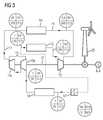
- the water separator 29is shown in the illustration FIG. 3 not shown, since this is not used.
- the working gasis passed through the cold storage 16. It is cooled from 20 ° C to -92 ° C. This measure serves to reduce the power consumption in order to operate the compressor operating second fluid energy machine.
- the compressorcompresses the working gas to 10 bar.
- Technically acceptablewould be a compression of up to 15 bar.
- the compressed working gaspasses through the heat accumulator 14 and is thereby heated to 500 ° C, the pressure decreases slightly to 9.8 bar.
- the working gasis expanded by the first fluid energy machine, which thus operates in this operating state as a turbine. There is a relaxation to 1 bar, wherein there is still a temperature of 183 ° C in the working gas at the output of the first fluid energy machine.
- the working gasis then passed through the low-temperature heat storage and thereby cools down to 130 ° C from.
- This heatmust be stored in order to serve in a subsequent charging process of the heat accumulator 14 and the cold accumulator 16 to preheat the working gas to 80 ° C (as already described above).
- the low-temperature heat storagethus operates as a buffer and is always charged just when the two other memory, d. H. the heat accumulator 14 and the cold storage 16 are discharged and vice versa.
Landscapes
- Engineering & Computer Science (AREA)
- Chemical & Material Sciences (AREA)
- Combustion & Propulsion (AREA)
- Mechanical Engineering (AREA)
- General Engineering & Computer Science (AREA)
- Power Engineering (AREA)
- Life Sciences & Earth Sciences (AREA)
- Sustainable Development (AREA)
- Sustainable Energy (AREA)
- Engine Equipment That Uses Special Cycles (AREA)
Abstract
Description
Translated fromGermanDie Erfindung betrifft eine Anlage zur Speicherung thermischer Energie, die einen Kreislauf für ein Arbeitsgas aufweist. Dabei werden in dem Kreislauf folgende Einheiten in der angegebenen Reihenfolge durch eine Leitung für das Arbeitsgas miteinander verbunden: eine erste thermische Fluidenergie-Maschine, ein Wärmespeicher, eine zweite thermische Fluidenergie-Maschine und ein Kältespeicher.
In Durchflussrichtung des Arbeitsgases vom Wärmespeicher zum Kältespeicher gesehen ist die erste ther Fluidenergie-Maschine als Arbeitsmaschine und die zweite thermische Fluidenergie-Maschine als Kraftmaschine geschaltet.The invention relates to a system for storing thermal energy having a circuit for a working gas. In the process, the following units are connected to one another in the sequence indicated by a line for the working gas: a first thermal fluid energy machine, a heat accumulator, a second thermal fluid energy machine and a cold accumulator.
Viewed in the direction of flow of the working gas from the heat storage to the cold storage, the first ther fluid energy machine is connected as a working machine and the second thermal fluid energy machine as an engine.
Weiterhin betrifft die Erfindung zwei Verfahren zum Betrieb dieser Anlage. Bei einem Verfahren zum Speicherung von thermischer Energie wird der Kreislauf in Richtung vom Wärmespeicher zum Kältespeicher durchlaufen, was der oben angegebenen Reihenfolge der Baueinheiten entspricht. Gemäß einem weiteren Verfahren, auf das sich die Erfindung ebenfalls bezieht, kann gespeicherte thermische Energie aus der Anlage auch umgewandelt werden, z. B. in mechanische Energie. Hierbei werden die Einheiten in umgekehrter Reihenfolge durchlaufen, mit anderen Worten wird die Durchflussrichtung des Arbeitsgases umgekehrt. Dieses passiert dann zuerst den Kältespeicher und dann den Wärmespeicher, wobei in diesem Fall die erste thermische Fluidenergie-Maschine als Kraftmaschine und die thermische Fluidenergie-Maschine als Arbeitsmaschine betrieben wird.Furthermore, the invention relates to two methods for operating this system. In a method for storing thermal energy, the circuit is traversed in the direction from the heat accumulator to the cold accumulator, which corresponds to the sequence of units specified above. According to another method, to which the invention also relates, stored thermal energy from the plant can also be converted, for. B. in mechanical energy. In this case, the units are run in reverse order, in other words, the flow direction of the working gas is reversed. This then happens first the cold storage and then the heat storage, in which case the first thermal fluid energy machine is operated as an engine and the thermal fluid energy machine as a work machine.
Die Begriffe Kraftmaschine und Arbeitsmaschine werden im Rahmen dieser Anmeldung so verwendet, dass eine Arbeitsmaschine mechanische Arbeit aufnimmt, um ihren Zweck zu erfüllen. Eine thermische Fluidenergie-Maschine, die als Arbeitsmaschine verwendet wird, wird somit als Verdichter oder als Kompressor verwendet. Demgegenüber verrichtet eine Kraftmaschine Arbeit, wobei eine thermische Fluidenergie-Maschine zur Verrichtung der Arbeit die im Arbeitsgas zur Verfügung stehende thermische Energie umwandelt. In diesem Fall wird die thermische Fluidenergie-Maschine also als Motor betrieben.The terms engine and work machine are used in the context of this application so that a work machine mechanical work to meet their purpose. A thermal fluid energy machine used as a work machine is thus used as a compressor or as a compressor. In contrast, an engine performs work, wherein a thermal fluid energy machine for performing the work converts the thermal energy available in the working gas. In this case, the thermal fluid energy machine is thus operated as a motor.
Der Begriff "thermische Fluidenergie-Maschine" bildet einen Oberbegriff von Maschinen, die einem Arbeitsfluid, im Zusammenhang mit dieser Anmeldung ein Arbeitsgas, thermische Energie entziehen oder diesem thermische Energie zuführen können. Unter thermischer Energie ist sowohl Wärmeenergie als auch Kälteenergie zu verstehen. Thermische Fluidenergie-Maschinen können beispielsweise als Kolbenmaschinen ausgeführt sein. Bevorzugt können auch hydrodynamische thermische Fluidenergie-Maschinen verwendet werden, deren Laufräder einen kontinuierlichen Fluss des Arbeitsgases erlauben. Vorzugsweise kommen axial wirkende Turbinen bzw. Verdichter zum Einsatz.The term "thermal fluid energy machine" forms a generic term for machines that can extract thermal energy from or supply thermal energy to a working fluid, in the context of this application, a working gas. By thermal energy is meant both thermal energy and cold energy. Thermal fluid energy machines can be designed, for example, as reciprocating engines. Preferably, hydrodynamic thermal fluid energy machines can be used, the wheels allow a continuous flow of the working gas. Preferably, axially acting turbines or compressors are used.
Das eingangs angegebene Prinzip ist beispielsweise gemäß der
Die Aufgabe der Erfindung besteht darin, eine Anlage zur Speicherung von thermischer Energie der eingangs angegebenen Art bzw. Verfahren zur Wandlung von thermischer Energie (beispielsweise Wandlung von mechanischer in thermischer Energie mit anschließender Speicherung oder Wandlung der gespeicherten thermischen Energie in mechanische Energie) anzugeben, mit der bzw. mit dem ein hoher Wirkungsgrad bei gleichzeitig vertretbaren Aufwand der verwendeten Baueinheiten möglich ist.The object of the invention is to provide a system for storing thermal energy of the type specified or method for the conversion of thermal energy (for example, conversion of mechanical into thermal energy with subsequent storage or conversion of the stored thermal energy into mechanical energy), with the or with the high efficiency at the same time reasonable cost of the units used is possible.
Diese Aufgabe wird mit der eingangs angegebenen Anlage erfindungsgemäß dadurch gelöst, dass vor der ersten Fluidenergie-Maschine zusätzlich ein Niedertemperatur-Wärmespeicher in dem Kreislauf vorgesehen ist. Dieser Wärmespeicher wird als Niedertemperatur-Wärmespeicher bezeichnet, weil das durch die Speicherung der Wärme erreichte Temperaturniveau prinzipbedingt unter dem Temperaturniveau des Wärmespeichers liegt. Der Wärmespeicher könnte im Vergleich zum Niedertemperatur-Wärmespeicher somit im Sinne der Erfindung auch als Hochtemperatur-Wärmespeicher bezeichnet werden. Wärme ist weiterhin durch den Bezug der Umgebungstemperatur der Anlage definiert. Alles über Umgebungstemperatur ist Wärme während alles unterhalb der Umgebungstemperatur Kälte ist. Damit wird auch klar, dass das Temperaturniveau des Kältespeichers unterhalb der Umgebungstemperatur liegt.This object is achieved with the above-mentioned system according to the invention, that in addition to the first fluid energy machine, a low-temperature heat storage is provided in the circuit. This heat storage is referred to as a low-temperature heat storage, because the temperature level reached by the storage of heat is inherently below the temperature level of the heat storage. The heat storage could thus be referred to as high-temperature heat storage in the context of the invention compared to the low-temperature heat storage. Heat is also defined by the reference to the ambient temperature of the system. Everything about ambient temperature is heat while everything is below ambient cold. This also makes it clear that the temperature level of the cold accumulator is below the ambient temperature.
Die Verwendung des Niedertemperatur-Wärmespeichers hat folgende Vorteile. Wird die Anlage zur Speicherung der thermischen Energie verwendet, so wird der Niedertemperatur-Wärmespeicher vor Passieren der in diesem Fall als Arbeitsmaschine (Verdichter) arbeitenden ersten Fluidenergie-Maschine durchlaufen. Hierdurch wird das Arbeitsgas bereits über Umgebungstemperatur aufgewärmt. Dies hat den Vorteil, dass die Arbeitsmaschine eine geringere Leistung aufnehmen muss, um die geforderte Temperatur des Arbeitsgases zu erreichen. Konkret soll der Wärmespeicher auf über 500°C aufgewärmt werden, was vorteilhaft anschließend an das Vorwärmen des Arbeitsgases auch mit technisch verfügbaren thermodynamischen Verdichtern erfolgen kann, die eine Verdichtung des Arbeitsgases auf 15 bar erlauben. Vorteilhaft kann daher auf Komponenten für die Baueinheiten der Anlage zurückgegriffen werden, die am Markt ohne kostspielige Modifikationen erhältlich sind.The use of the low-temperature heat accumulator has the following advantages. If the system is used to store the thermal energy, the low-temperature heat storage is passed before passing in this case as a working machine (compressor) working first fluid energy machine. As a result, the working gas is already warmed above ambient temperature. This has the advantage that the working machine has to absorb less power in order to achieve the required temperature of the working gas. Specifically, the heat storage to over 500 ° C to be warmed up, which can advantageously be done after the preheating of the working gas with technically available thermodynamic compressors, which allow a compression of the working gas to 15 bar. Advantageously, therefore, can be used on components for the units of the system, which are available on the market without costly modifications.
Das Arbeitsgas kann wahlweise in einem geschlossenen oder einem offenen Kreislauf geführt werden. Ein offener Kreislauf verwendet als Arbeitsgas immer die Umgebungsluft. Diese wird aus der Umgebung angesaugt und am Ende des Prozesses auch wieder in diese entlassen, so dass die Umgebung den offenen Kreislauf schließt. Ein geschlossener Kreislauf erlaubt auch die Verwendung eines anderen Arbeitsgases als Umgebungsluft. Dieses Arbeitsgas wird in dem geschlossenen Kreislauf geführt. Da eine Entspannung in die Umgebung bei gleichzeitiger Einstellung des Umgebungsdruckes und der Umgebungstemperatur entfällt, muss das Arbeitsgas im Falle eines geschlossenen Kreislaufes durch einen Wärmetauscher geführt werden, der eine Abgabe bzw. Aufnahme von Wärme des Arbeitsgases an die Umgebung erlaubt.The working gas can be fed either in a closed or an open circuit. An open circuit always uses the ambient air as working gas. This is sucked from the environment and at the end of the process also released back into it, so that the environment of the open Circuit closes. A closed circuit also allows the use of a different working gas than ambient air. This working gas is guided in the closed circuit. Since a relaxation in the environment with simultaneous adjustment of the ambient pressure and the ambient temperature is eliminated, the working gas in the case of a closed circuit must be passed through a heat exchanger, which allows a release or absorption of heat of the working gas to the environment.
Gemäß einer vorteilhaften Ausgestaltung der Erfindung ist vorgesehen, dass der Kreislauf als offener Kreislauf ausgebildet ist und die zweite thermische Fluidenergie-Maschine aus zwei Stufen aufgebaut ist, wobei zwischen den Stufen ein Wasserabscheider für das Arbeitsgas vorgesehen ist. Hierbei wird dem Umstand Rechnung getragen, dass in der Umgebungsluft Luftfeuchtigkeit enthalten ist. Durch eine Entspannung des Arbeitsgases in einer einzigen Stufe kann es dazu kommen, dass die Luftfeuchtigkeit aufgrund der starken Abkühlung des Arbeitsgases auf beispielsweise -114°C gefriert und hierbei die thermische Fluidenergie-Maschine beschädigt. Insbesondere können Turbinenschaufeln durch Vereisung nachhaltig beschädigt werden. Eine Entspannung des Arbeitsgases in zwei Schritten ermöglicht es jedoch, kondensiertes Wasser in einem Wasserabscheider hinter der ersten Stufe beispielsweise bei 5°C abzuscheiden, so dass dieses bei einer weiteren Abkühlung des Arbeitsgases in der zweiten Turbinenstufe bereits entfeuchtet ist und eine Eisbildung verhindert oder zumindest verringert werden kann. Vorteilhaft wird das Risiko einer Beschädigung der zweiten Fluidenergie-Maschine hiermit verringert.According to an advantageous embodiment of the invention, it is provided that the circuit is designed as an open circuit and the second thermal fluid energy machine is constructed of two stages, wherein between the stages, a water separator is provided for the working gas. This takes into account the fact that humidity is contained in the ambient air. By a relaxation of the working gas in a single stage, it may happen that the humidity due to the strong cooling of the working gas to eg -114 ° C, thereby damaging the thermal fluid energy machine. In particular, turbine blades can be permanently damaged by icing. However, a relaxation of the working gas in two steps makes it possible to separate condensed water in a water separator behind the first stage, for example at 5 ° C, so that it is already dehumidified in a further cooling of the working gas in the second turbine stage and prevents or at least reduces ice formation can be. Advantageously, the risk of damaging the second fluid energy machine is thereby reduced.
Wird ein geschlossener Kreislauf verwendet und, wie bereits beschrieben, ein Wärmetauscher in den Kreislauf eingebaut, kann die Verwendung eines Wasserabscheiders sowie einer zweistufigen zweiten thermischen Fluidenergie-Maschine entfallen. Als Arbeitsgas kann in diesem Fall beispielsweise auch entfeuchtete Umgebungsluft verwendet werden, deren Befeuchtung durch die Geschlossenheit des Kreislaufes ausgeschlossen ist. Aber auch andere Arbeitsgase können Verwendung finden.If a closed circuit is used and, as already described, a heat exchanger installed in the circuit, the use of a water separator and a two-stage second thermal fluid energy machine can be omitted. As working gas can be used in this case, for example, dehumidified ambient air, their humidification is excluded by the closed nature of the cycle. But other working gases can be used.
Eine besondere Ausgestaltung der erfindungsgemäßen Anlage sieht vor, dass mit der ersten thermischen Fluidenergie-Maschine eine dritte thermische Fluidenergie-Maschine und/oder mit der zweiten thermischen Fluidenergie-Maschine eine vierte thermische Fluidenergie-Maschine im Kreislauf parallel geschaltet ist. Dabei ist jeweils ein Ventilmechanismus zwischen der ersten und der dritten und/oder der zweiten und der vierten thermischen Fluidenergie-Maschine vorgesehen. Durch Schalten des Ventilmechanismus kann nun vorteilhaft je nach Durchflussrichtung des Arbeitsgases jeweils die eine oder die andere Fluidenergie-Maschine ausgewählt werden. Dies hat den Vorteil, dass die jeweilige zur Anwendung kommende Fluidenergie-Maschine auf den zu schaltenden Betriebszustand optimiert werden kann. Da bei Verwendung von lediglich zwei Fluidenergie-Maschinen beide in Abhängigkeit der Durchflussrichtung sowohl als Arbeitsmaschine als auch als Kraftmaschine verwendet werden müssen, kann ohne das Vorsehen von zusätzlichen Fluidenergie-Maschinen nur ein konstruktiver Kompromiss gewählt werden. Da jedoch sowohl im thermischen Ladebetrieb wie auch im thermischen Entladebetrieb ein möglichst hoher Wirkungsgrad angestrebt wird, erlaubt die Parallelschaltung von Fluidenergie-Maschinen, sowohl das Verfahren zur Speicherung der thermischen Energie als auch das Verfahren zur Umwandlung der thermischen Energie bei optimalem Wirkungsgrad vorzunehmen.A particular embodiment of the system according to the invention provides that the first thermal fluid energy machine, a third thermal fluid energy machine and / or with the second thermal fluid energy machine, a fourth thermal fluid energy machine is connected in parallel in the circuit. In each case, a valve mechanism is provided between the first and the third and / or the second and the fourth thermal fluid energy machine. By switching the valve mechanism can now be selected depending on the direction of flow of the working gas in each case one or the other fluid energy machine. This has the advantage that the respective fluid energy machine used for the application can be optimized for the operating state to be switched. Since using only two fluid energy machines both as a function of the flow direction must be used both as a work machine and as an engine, only a constructive compromise can be chosen without the provision of additional fluid energy machines. However, since the highest possible efficiency is sought both in the thermal charging operation as well as in the thermal discharge operation, the parallel connection of fluid energy machines allows to carry out both the method for storing the thermal energy and the method for converting the thermal energy with optimum efficiency.
Die Lösung der Aufgabe gelingt überdies durch das eingangs genannte Verfahren zur Speicherung von thermischer Energie dadurch, dass vor der ersten Fluidenergie-Maschine ein Niedertemperatur-Wärmespeicher vom Arbeitsgas durchflossen wird. Das heißt, dass das Arbeitsgas durch den Niedertemperatur-Wärmespeicher aufgewärmt in die erste Fluidenergie-Maschine eingespeist wird. Hierdurch werden die bereits erläuterten Vorteile erreicht. Vorteilhaft kann das Arbeitsgas in dem Niedertemperatur-Wärmespeicher auf eine Temperatur zwischen 60°C und 100°C besonders vorteilhaft auf eine Temperatur von 80°C erwärmt werden. Wie bereits erwähnt, kann dann gemäß einer weiteren Ausgestaltung der Erfindung das Arbeitsgas auf höchstens 15 bar verdichtet werden, wodurch sich Temperaturen des Arbeitsgrades von bis zu 550°C erreichen lassen.The solution of the problem also succeeds by the aforementioned method for storing thermal energy in that before the first fluid energy machine, a low-temperature heat storage tank is traversed by the working gas. That is, the working gas is fed by the low-temperature heat storage warmed up in the first fluid energy machine. As a result, the already explained advantages are achieved. Advantageously, the working gas in the low-temperature heat storage to a temperature between 60 ° C and 100 ° C are particularly advantageously heated to a temperature of 80 ° C. As already mentioned, according to a further embodiment of the invention, the working gas can be compressed to a maximum of 15 bar, whereby temperatures of the working degree of up to 550 ° C can be achieved.
Genauso wird Aufgabe durch das eingangs genannte Verfahren zur Umwandlung von thermischer Energie dadurch gelöst, dass (bei umgekehrter Flussrichtung des Arbeitsgases) hinter der ersten Fluidenergie-Maschine ein Niedertemperatur-Wärmespeicher vom Arbeitsgas durchflossen wird. Hierbei handelt es sich bezogen auf die verwendete Anlage natürlich um denselben Niedertemperatur-Wärmespeicher, der bei dem oben erwähnten Verfahren zur Speicherung der thermischen Energie verwendet wird. Dies hat nämlich den Vorteil, dass nach einem Vorgang zur Umwandlung der thermischen Energie der Niedertemperatur-Wärmespeicher wieder aufgeladen wird, während der Wärmespeicher und der Kältespeicher entladen werden. Wird der Prozess in einem Verfahren zur Speicherung von thermischer Energie wieder umgekehrt, so steht die in Niedertemperatur-Wärmespeicher zwischengespeicherte Energie nun zur Vorwärmung des Arbeitsgases zur Verfügung. Nur bei Inbetriebnahme der Anlage muss die Wärme beim erstmaligen Durchlaufen des Verfahrens zur Speicherung thermischer Energie auf anderem Wege zur Verfügung gestellt werden, da diese vorher noch nicht durch ein Verfahren zur Umwandlung der thermischen Energie zur Verfügung gestellt werden konnte. Wird diese sonst im Niedertemperatur-Wärmespeicher gespeicherte Energie nicht zur Verfügung gestellt, so funktioniert das Verfahren zur Speicherung von thermischer Energie dennoch, wenn auch nicht mit dem gewünschten Wirkungsgrad. Allerdings wird bei mehrfacher Umkehrung des Prozesses der geforderte Sollzustand der Anlage auch ohne Hinzuziehung von Fremdenergie erreicht.Similarly, the object is achieved by the aforementioned method for the conversion of thermal energy in that (in the reverse flow direction of the working gas) behind the first fluid energy machine, a low-temperature heat storage tank is traversed by the working gas. Of course, with respect to the equipment used, this is the same low-temperature heat storage used in the thermal energy storage method mentioned above. This has the advantage that after a process for converting the thermal energy of the low-temperature heat storage is recharged while the heat storage and the cold storage are discharged. If the process is reversed again in a process for storing thermal energy, the energy temporarily stored in low-temperature heat storage is now available for preheating the working gas. Only when the system is put into operation, the heat must be provided by other means when first passing through the process for storing thermal energy, since this could not previously be provided by a method for the conversion of thermal energy available. If this otherwise stored in the low-temperature heat storage energy is not provided, the process for storing thermal energy still works, though not with the desired efficiency. However, with repeated reversal of the process, the required nominal state of the system is achieved even without the use of external energy.
Vorteilhaft kann das Arbeitsgas in dem Niedertemperatur-Wärmespeicher auf eine Temperatur zwischen 100°C und 160°C erwärmt werden. Besonders vorteilhaft ist eine Erwärmung auf 130°C. Vorteilhaft ist dabei weiterhin, wenn das Arbeitsgas durch die zweite thermische Fluidenergie-Maschine auf höchstens 10 bar verdichtet wird. Auch hierbei handelt es sich um einen sinnvollen technischen Kompromiss bei der Abwägung zwischen Aufwand und Nutzen.Advantageously, the working gas can be heated in the low-temperature heat storage to a temperature between 100 ° C and 160 ° C. Particularly advantageous is a heating to 130 ° C. It is also advantageous if the working gas is compressed by the second thermal fluid energy machine to at most 10 bar. Here, too, is a meaningful technical compromise in the balance between effort and benefits.
Weitere Einzelheiten der Erfindung werden nachfolgend anhand der Zeichnung beschrieben. Gleiche oder sich entsprechende Zeichnungselemente sind hierbei jeweils mit denselben Bezugszeichen versehen und werden nur insoweit mehrfach erläutert, wie sich Unterschiede zwischen den einzelnen Figuren ergeben. Es zeigen:
Figur 1- ein Ausführungsbeispiel der erfindungsgemäßen Anlage als Schaltbild und
- Figur 2 und 3
- Ausführungsbeispiele des erfindungsgemäßen Verfahrens anhand von weiteren Schaltbildern.
- FIG. 1
- an embodiment of the system according to the invention as a circuit diagram and
- FIGS. 2 and 3
- Embodiments of the method according to the invention with reference to further circuit diagrams.
Eine Anlage zur Speicherung thermischer Energie gemäß
In
Weiterhin ist in
Der Aufbau des Niedertemperatur-Wärmespeichers 12, des Wärmespeichers 14 und des Kältespeichers 16 bei der Anlage gemäß
Anhand der Anlage gemäß den
In der Modellrechnung gelangt das Arbeitsgas mit einem bar und 20°C in den (vorher aufgeladenen) Niedertemperatur-Wärmespeicher und verlässt diesen mit einer Temperatur von 80°C. Durch Komprimierung mittels der als Verdichter arbeitenden ersten Fluidenergie-Maschine 13 kommt es zu einer Druckerhöhung auf 15 bar und infolgedessen auch zu einer Temperaturerhöhung auf 547°C. Dieser Berechnung liegt folgende Formel zugrunde
T2 die Temperatur am Verdichterausgang,
T1 die Temperatur am Verdichtereingang,
ηc der isentropische Wirkungsgrad des Kompressors,
n das Druckverhältnis (hier 15:1) und
K die Kompressibilität ist, die bei Luft 1,4 beträgt.In the model calculation, the working gas enters the (previously charged) low-temperature heat storage tank with a bar and 20 ° C and leaves it with a temperature of 80 ° C. Compression by means of the first
T2 is the temperature at the compressor outlet,
T1 is the temperature at the compressor inlet,
ηc the isentropic efficiency of the compressor,
n the pressure ratio (here 15: 1) and
K is the compressibility, which is 1.4 in air.
Der isentropische Wirkungsgrad ηc kann einem Kompressor mit 0,85 vorausgesetzt werden.The isentropic efficiency ηc can be assumed to be a compressor with 0.85.
Das erhitzte Arbeitsgas durchläuft nun den Wärmespeicher 14, wo der Hauptteil der verfügbaren thermischen Energie gespeichert wird. Während der Speicherung kühlt sich das Arbeitsgas auf 20°C ab, während der Druck (abgesehen von strömungsbedingten Druckverlusten) mit 15 bar erhalten bleibt. Anschließend wird das Arbeitsgas in zwei in Serie geschalteten Stufen 15a, 15b einer zweiten Fluidenergie-Maschine entspannt, so dass es auf einem Druckniveau von einem bar anlangt. Dabei kühlt sich das Arbeitsgas nach der ersten Stufe auf 5°C und nach der zweiten Stufe auf -114°C ab. Grundlage für diese Berechnung ist ebenfalls die oben angegebene Formel.The heated working gas now passes through the
In den Teil der Leitung 11, der die beiden Stufen der zweiten Fluidenergie-Maschine 15a, 15b in Form einer Hochdruckturbine und einer Niederdruckturbine verbindet, ist zusätzlich ein Wasserabscheider 29 vorgesehen. Dieser ermöglicht nach einer ersten Entspannung eine Trocknung der Luft, so dass die in dieser enthaltene Luftfeuchtigkeit in der zweiten Stufe 15b der zweiten Fluidenergie-Maschine 15 nicht zu einer Vereisung der Turbinenblätter führt.In the part of the
Im weiteren Verlauf entzieht das entspannte und daher abgekühlte Arbeitsgas dem Kältespeicher 16 Wärme und wird dadurch auf 0°C erwärmt. Auf diesem Weg wird Kälteenergie im Kältespeicher 16 gespeichert, die bei einer anschließenden Energiegewinnung genutzt werden kann. Vergleicht man die Temperatur des Arbeitsgases am Ausgang des Kältespeichers 16 und am Eingang des Niedertemperatur-Wärmespeichers 12, so wird deutlich, warum für den Fall eines geschlossenen Kreislaufs der Wärmetauscher 17 zur Verfügung gestellt werden muss. Hier kann das Arbeitsgas wieder auf Umgebungstemperatur von 20°C aufgewärmt werden, wodurch der Umgebung Wärme entzogen wird, die dem Prozess zur Verfügung gestellt wird. Eine solche Maßnahme kann selbstverständlich entfallen, wenn das Arbeitsgas direkt aus der Umgebung angesaugt wird, da dies bereits Umgebungstemperatur aufweist.In the further course, the relaxed and therefore cooled working gas withdraws heat from the
Mittels
Das Arbeitsgas wird durch den Kältespeicher 16 geleitet. Dabei wird es von 20°C auf -92°C abgekühlt. Diese Maßnahme dient zur Reduzierung der Leistungsaufnahme, um die als Kompressor arbeitende zweite Fluidenergie-Maschine zu betreiben. Die Leistungsaufnahme wird um den Faktor entsprechend des Temperaturunterschiedes in Kelvin also 293K/181K = 1,62 reduziert. In dem Beispiel komprimiert der Kompressor das Arbeitsgas auf 10 bar. Hierbei steigt die Temperatur auf 100°C. Technisch vertretbar wäre auch eine Kompression von bis zu 15 bar. Das komprimierte Arbeitsgas durchläuft den Wärmespeicher 14 und wird dadurch auf 500°C aufgeheizt, wobei der Druck leicht auf 9,8 bar abnimmt. Anschließend wird das Arbeitsgas durch die erste Fluidenergie-Maschine entspannt, die somit in diesem Betriebszustand als Turbine arbeitet. Es erfolgt eine Entspannung auf 1 bar, wobei am Ausgang der ersten Fluidenergie-Maschine immer noch eine Temperatur von 183°C im Arbeitsgas vorliegt.The working gas is passed through the
Um diese Restwärme ebenfalls ausnutzen zu können, wird das Arbeitsgas anschließend durch den Niedertemperatur-Wärmespeicher geleitet und kühlt sich dadurch noch auf 130°C ab. Diese Wärme muss gespeichert werden, um in einem nachfolgenden Ladeprozess des Wärmespeichers 14 und des Kältespeichers 16 zur Vorwärmung des Arbeitsgases auf 80°C zu dienen (wie oben bereits beschrieben). Der Niedertemperatur-Wärmespeicher arbeitet somit als Zwischenspeicher und wird immer gerade dann aufgeladen, wenn die beiden anderen Speicher, d. h. der Wärmespeicher 14 und der Kältespeicher 16 entladen werden und anders herum.In order to be able to exploit this residual heat, the working gas is then passed through the low-temperature heat storage and thereby cools down to 130 ° C from. This heat must be stored in order to serve in a subsequent charging process of the
Claims (10)
Translated fromGermandadurch gekennzeichnet,
dass vor der ersten Fluidenergie-Maschine (13) ein Niedertemperatur-Wärmespeicher (12) in dem Kreislauf vorgesehen ist.Thermal energy storage system comprising a working gas circuit, in which circuit the following units are connected in the order indicated by a working gas duct (11):
characterized,
that is provided in the circuit before the first fluid energy machine (13) a low-temperature heat storage (12).
dadurch gekennzeichnet,
dass der Kreislauf als offener Kreislauf ausgebildet ist und die zweite thermische Fluidenergie-Maschine (15) aus zwei Stufen (15a, 15b) aufgebaut ist, wobei zwischen den Stufen (15a, 15b) ein Wasserabscheider (29) für das Arbeitsgas vorgesehen ist.Plant according to claim 1,
characterized,
in that the circuit is designed as an open circuit and the second thermal fluid energy machine (15) is constructed from two stages (15a, 15b), wherein a water separator (29) for the working gas is provided between the stages (15a, 15b).
dadurch gekennzeichnet,
dass der Kreislauf als geschlossener Kreislauf ausgeführt ist und zwischen dem Kältespeicher (16) und dem Niedertemperatur-Wärmespeicher (12) ein Wärmetauscher (17) im Kreislauf angeordnet ist.Plant according to claim 1,
characterized,
that the circuit is designed as a closed circuit and between the cold storage (16) and the low-temperature heat storage (12), a heat exchanger (17) is arranged in the circuit.
dadurch gekennzeichnet,
dass mit der ersten thermischen Fluidenergie-Maschine (13) eine dritte thermische Fluidenergie-Maschine (18) und/oder mit der zweiten thermischen Fluidenergie-Maschine (15) eine vierte thermische Fluidenergie-Maschine (19) im Kreislauf parallel geschaltet ist, wobei jeweils ein Ventilmechanismus (20) zwischen der ersten und der dritten und/oder der zweiten und der vierten thermischen Fluidenergie-Maschine vorgesehen ist.Plant according to one of claims 1 to 3,
characterized,
in that with the first thermal fluid energy machine (13) a third thermal fluid energy machine (18) and / or a fourth thermal fluid energy machine (19) is connected in parallel with the second thermal fluid energy machine (15), each having a valve mechanism (20) between the first and third and / or second and fourth thermal fluid energy machines is provided.
dadurch gekennzeichnet,
dass vor der ersten Fluidenergie-Maschine (13) ein Niedertemperatur-Wärmespeicher (12) vom Arbeitsgas durchflossen wird.Process for the storage of thermal energy, in which a working gas passes through a cycle, wherein the following units are flowed through in the sequence in the cycle:
characterized,
that before the first fluid energy machine (13), a low-temperature heat storage (12) is flowed through by the working gas.
dadurch gekennzeichnet,
dass das Arbeitsgas in dem Niedertemperatur-Wärmespeicher auf eine Temperatur zwischen 60 °C und 100 °C, insbesondere auf 80 °C erwärmt wird.Method according to claim 5,
characterized,
that the working gas is heated in the low-temperature heat storage to a temperature between 60 ° C and 100 ° C, in particular to 80 ° C.
dadurch gekennzeichnet,
dass das Arbeitsgas durch die erste thermische Fluidenergie-Maschine auf höchstens 20 bar, bevorzugt höchstens 15 bar, verdichtet wird.Method according to claim 5 or 6,
characterized,
that the working gas is compressed by the first thermal fluid energy machine to at most 20 bar, preferably at most 15 bar.
dass hinter der ersten Fluidenergie-Maschine (13) ein Niedertemperatur-Wärmespeicher (12) vom Arbeitsgas durchflossen wird.Process for the conversion of thermal energy, in which a working gas passes through a cycle, wherein the following units are flowed through in the sequence in the cycle:
that behind the first fluid energy machine (13) a low-temperature heat accumulator (12) is flowed through by the working gas.
dadurch gekennzeichnet,
dass das Arbeitsgas in dem Niedertemperaturspeicher auf eine Temperatur zwischen 100 °C und 160 °C, insbesondere auf 130 °C abgekühlt wird.Method according to claim 5,
characterized,
that the working gas is cooled in the low-temperature storage to a temperature between 100 ° C and 160 ° C, in particular to 130 ° C.
dadurch gekennzeichnet,
dass das Arbeitsgas durch die zweite thermische Fluidenergie-Maschine auf höchstens 15 bar, bevorzugt höchstens 10 bar, verdichtet wird.Method according to claim 5 or 6,
characterized,
that the working gas is compressed by the second thermal fluid energy machine to at most 15 bar, preferably at most 10 bar.
Priority Applications (5)
| Application Number | Priority Date | Filing Date | Title |
|---|---|---|---|
| EP11183270AEP2574739A1 (en) | 2011-09-29 | 2011-09-29 | Assembly for storing thermal energy and method for its operation |
| US14/345,237US20140352295A1 (en) | 2011-09-29 | 2012-09-26 | Installation for storing thermal energy and method for the operation thereof |
| PCT/EP2012/068902WO2013045463A1 (en) | 2011-09-29 | 2012-09-26 | Installation for storing thermal energy and method for the operation thereof |
| CN201280046812.9ACN103827448A (en) | 2011-09-29 | 2012-09-26 | Installation for storing thermal energy and method for the operation thereof |
| EP12770061.5AEP2761142A1 (en) | 2011-09-29 | 2012-09-26 | Installation for storing thermal energy and method for the operation thereof |
Applications Claiming Priority (1)
| Application Number | Priority Date | Filing Date | Title |
|---|---|---|---|
| EP11183270AEP2574739A1 (en) | 2011-09-29 | 2011-09-29 | Assembly for storing thermal energy and method for its operation |
Publications (1)
| Publication Number | Publication Date |
|---|---|
| EP2574739A1true EP2574739A1 (en) | 2013-04-03 |
Family
ID=47008561
Family Applications (2)
| Application Number | Title | Priority Date | Filing Date |
|---|---|---|---|
| EP11183270AWithdrawnEP2574739A1 (en) | 2011-09-29 | 2011-09-29 | Assembly for storing thermal energy and method for its operation |
| EP12770061.5AWithdrawnEP2761142A1 (en) | 2011-09-29 | 2012-09-26 | Installation for storing thermal energy and method for the operation thereof |
Family Applications After (1)
| Application Number | Title | Priority Date | Filing Date |
|---|---|---|---|
| EP12770061.5AWithdrawnEP2761142A1 (en) | 2011-09-29 | 2012-09-26 | Installation for storing thermal energy and method for the operation thereof |
Country Status (4)
| Country | Link |
|---|---|
| US (1) | US20140352295A1 (en) |
| EP (2) | EP2574739A1 (en) |
| CN (1) | CN103827448A (en) |
| WO (1) | WO2013045463A1 (en) |
Cited By (4)
| Publication number | Priority date | Publication date | Assignee | Title |
|---|---|---|---|---|
| CN105793548A (en)* | 2013-10-16 | 2016-07-20 | Abx能源有限公司 | Eight-transition thermal differential machine with thermodynamic cycle and process control |
| WO2017081186A1 (en) | 2015-11-10 | 2017-05-18 | Peter Ortmann | Pumped-heat electricity storage device and method for the load control thereof |
| CN113137782A (en)* | 2021-05-20 | 2021-07-20 | 东北电力大学 | Heat pump heating device based on vortex wind collecting type wind power generation |
| US11591957B2 (en) | 2017-10-24 | 2023-02-28 | Tes Caes Technology Limited | Energy storage apparatus and method |
Families Citing this family (26)
| Publication number | Priority date | Publication date | Assignee | Title |
|---|---|---|---|---|
| US10094219B2 (en) | 2010-03-04 | 2018-10-09 | X Development Llc | Adiabatic salt energy storage |
| WO2014052927A1 (en) | 2012-09-27 | 2014-04-03 | Gigawatt Day Storage Systems, Inc. | Systems and methods for energy storage and retrieval |
| CN105299945B (en)* | 2014-08-01 | 2019-02-01 | 江洪泽 | Matter boosting energy storage device and method and utility system are deposited in Mixed Gas Condensation separation |
| CN105114138B (en)* | 2015-08-12 | 2016-08-31 | 中国科学院工程热物理研究所 | A kind of low temperature energy-storing and power-generating system and operation method thereof |
| CN105179033B (en)* | 2015-08-12 | 2017-05-31 | 中国科学院工程热物理研究所 | The system and its operation method of a kind of utilization cryogenic cold energy storage electric energy |
| US10458284B2 (en) | 2016-12-28 | 2019-10-29 | Malta Inc. | Variable pressure inventory control of closed cycle system with a high pressure tank and an intermediate pressure tank |
| US11053847B2 (en) | 2016-12-28 | 2021-07-06 | Malta Inc. | Baffled thermoclines in thermodynamic cycle systems |
| US10233787B2 (en) | 2016-12-28 | 2019-03-19 | Malta Inc. | Storage of excess heat in cold side of heat engine |
| US10233833B2 (en) | 2016-12-28 | 2019-03-19 | Malta Inc. | Pump control of closed cycle power generation system |
| US10221775B2 (en) | 2016-12-29 | 2019-03-05 | Malta Inc. | Use of external air for closed cycle inventory control |
| US10801404B2 (en) | 2016-12-30 | 2020-10-13 | Malta Inc. | Variable pressure turbine |
| US10436109B2 (en) | 2016-12-31 | 2019-10-08 | Malta Inc. | Modular thermal storage |
| CN110206599B (en)* | 2019-06-04 | 2022-03-29 | 中国科学院工程热物理研究所 | Combined cooling, heating and power system |
| CN110206598B (en)* | 2019-06-04 | 2022-04-01 | 中国科学院工程热物理研究所 | Heat pump energy storage power generation system based on indirect cold storage and heat storage |
| CN116575992A (en) | 2019-11-16 | 2023-08-11 | 马耳他股份有限公司 | Dual power system pumping thermoelectric storage state conversion |
| US11454167B1 (en) | 2020-08-12 | 2022-09-27 | Malta Inc. | Pumped heat energy storage system with hot-side thermal integration |
| CA3189001A1 (en) | 2020-08-12 | 2022-02-17 | Mert Geveci | Pumped heat energy storage system with modular turbomachinery |
| US11396826B2 (en) | 2020-08-12 | 2022-07-26 | Malta Inc. | Pumped heat energy storage system with electric heating integration |
| EP4193036A1 (en) | 2020-08-12 | 2023-06-14 | Malta Inc. | Pumped heat energy storage system with steam cycle |
| US11486305B2 (en)* | 2020-08-12 | 2022-11-01 | Malta Inc. | Pumped heat energy storage system with load following |
| US11480067B2 (en) | 2020-08-12 | 2022-10-25 | Malta Inc. | Pumped heat energy storage system with generation cycle thermal integration |
| US11286804B2 (en) | 2020-08-12 | 2022-03-29 | Malta Inc. | Pumped heat energy storage system with charge cycle thermal integration |
| DK181096B1 (en)* | 2021-04-14 | 2022-12-12 | Stiesdal Storage As | Thermal energy storage system with a spray of phase change material and method of its operation |
| DK181199B1 (en)* | 2021-09-20 | 2023-04-25 | Stiesdal Storage As | A thermal energy storage system with environmental air exchange and a method of its operation |
| EP4430285A1 (en) | 2021-12-14 | 2024-09-18 | Malta Inc. | Pumped heat energy storage system integrated with coal-fired energy generation unit |
| PT4269758T (en)* | 2022-04-28 | 2025-03-31 | Borealis Ag | Method for recovering energy |
Citations (3)
| Publication number | Priority date | Publication date | Assignee | Title |
|---|---|---|---|---|
| US5436508A (en) | 1991-02-12 | 1995-07-25 | Anna-Margrethe Sorensen | Wind-powered energy production and storing system |
| WO2009044139A2 (en)* | 2007-10-03 | 2009-04-09 | Isentropic Limited | Energy storage |
| FR2922608A1 (en)* | 2007-10-19 | 2009-04-24 | Saipem S A Sa | INSTALLATION AND METHOD FOR STORING AND RETURNING ELECTRIC ENERGY USING A PISTON GAS COMPRESSION AND RELIEF UNIT |
Family Cites Families (8)
| Publication number | Priority date | Publication date | Assignee | Title |
|---|---|---|---|---|
| US2973622A (en)* | 1959-04-07 | 1961-03-07 | Nettel Frederick | Elastic fluid power plant for intermittent operation |
| JPH1047829A (en)* | 1996-07-29 | 1998-02-20 | Nippon Sanso Kk | Method and apparatus for freezing an object to be frozen in a freezer warehouse |
| JP4147697B2 (en)* | 1999-09-20 | 2008-09-10 | アイシン精機株式会社 | Pulse tube refrigerator |
| AUPQ785000A0 (en)* | 2000-05-30 | 2000-06-22 | Commonwealth Scientific And Industrial Research Organisation | Heat engines and associated methods of producing mechanical energy and their application to vehicles |
| CN101680649A (en)* | 2007-03-20 | 2010-03-24 | 西门子公司 | Method and apparatus for intermediate reheater firing when solar energy is directly vaporized in a solar thermal power plant |
| FR2916101B1 (en)* | 2007-05-11 | 2009-08-21 | Saipem Sa | INSTALLATION AND METHODS FOR STORAGE AND RESTITUTION OF ELECTRICAL ENERGY |
| EP2241737B1 (en)* | 2009-04-14 | 2015-06-03 | ABB Research Ltd. | Thermoelectric energy storage system having two thermal baths and method for storing thermoelectric energy |
| US20110100010A1 (en)* | 2009-10-30 | 2011-05-05 | Freund Sebastian W | Adiabatic compressed air energy storage system with liquid thermal energy storage |
- 2011
- 2011-09-29EPEP11183270Apatent/EP2574739A1/ennot_activeWithdrawn
- 2012
- 2012-09-26WOPCT/EP2012/068902patent/WO2013045463A1/enactiveApplication Filing
- 2012-09-26USUS14/345,237patent/US20140352295A1/ennot_activeAbandoned
- 2012-09-26CNCN201280046812.9Apatent/CN103827448A/enactivePending
- 2012-09-26EPEP12770061.5Apatent/EP2761142A1/ennot_activeWithdrawn
Patent Citations (4)
| Publication number | Priority date | Publication date | Assignee | Title |
|---|---|---|---|---|
| US5436508A (en) | 1991-02-12 | 1995-07-25 | Anna-Margrethe Sorensen | Wind-powered energy production and storing system |
| WO2009044139A2 (en)* | 2007-10-03 | 2009-04-09 | Isentropic Limited | Energy storage |
| US20100257862A1 (en) | 2007-10-03 | 2010-10-14 | Isentropic Limited | Energy Storage |
| FR2922608A1 (en)* | 2007-10-19 | 2009-04-24 | Saipem S A Sa | INSTALLATION AND METHOD FOR STORING AND RETURNING ELECTRIC ENERGY USING A PISTON GAS COMPRESSION AND RELIEF UNIT |
Cited By (4)
| Publication number | Priority date | Publication date | Assignee | Title |
|---|---|---|---|---|
| CN105793548A (en)* | 2013-10-16 | 2016-07-20 | Abx能源有限公司 | Eight-transition thermal differential machine with thermodynamic cycle and process control |
| WO2017081186A1 (en) | 2015-11-10 | 2017-05-18 | Peter Ortmann | Pumped-heat electricity storage device and method for the load control thereof |
| US11591957B2 (en) | 2017-10-24 | 2023-02-28 | Tes Caes Technology Limited | Energy storage apparatus and method |
| CN113137782A (en)* | 2021-05-20 | 2021-07-20 | 东北电力大学 | Heat pump heating device based on vortex wind collecting type wind power generation |
Also Published As
| Publication number | Publication date |
|---|---|
| CN103827448A (en) | 2014-05-28 |
| WO2013045463A1 (en) | 2013-04-04 |
| EP2761142A1 (en) | 2014-08-06 |
| US20140352295A1 (en) | 2014-12-04 |
Similar Documents
| Publication | Publication Date | Title |
|---|---|---|
| EP2574739A1 (en) | Assembly for storing thermal energy and method for its operation | |
| EP2748434B1 (en) | Assembly for storing thermal energy | |
| DE102012206296A1 (en) | Plant for storage and delivery of thermal energy and method of operation thereof | |
| EP1917428B1 (en) | Method of operating a power plant which comprises a pressure storage vessel | |
| EP2823156B1 (en) | System for storing and outputting thermal energy | |
| EP2808500A1 (en) | Heat pump cycle with a first thermal fluid energy machine and a second thermal fluid energy machine | |
| EP2885512A2 (en) | Method for charging and discharging a heat accumulator and system for storing and releasing thermal energy suitable for said method | |
| EP2653670A1 (en) | Assembly for storing and emitting thermal energy with a heat storage device and a cold air reservoir and method for its operation | |
| EP4010567B1 (en) | Thermal energy storage system comprising a packed-bed heat storage unit and a packed-bed cold storage unit, and method for operating a thermal energy storage system | |
| EP2739919A1 (en) | Energy-storing device and method for storing energy | |
| WO2016131920A1 (en) | Steam power plant and method for operating same | |
| EP3006682B1 (en) | Device and method for operating a heating distribution station | |
| DE102014118466B4 (en) | Apparatus and method for temporarily storing gas and heat | |
| EP2574738A1 (en) | Assembly for storing thermal energy | |
| DE102007027725A1 (en) | Method for producing useful heating and cooling energy, involves absorbing ambient air with turbo-heat pump, where compressed and warmed up air is produced in compression impeller of heat pump | |
| DE202005003611U1 (en) | Thermal electric station for producing and storing electrical energy comprises a compressed air storage unit with heat exchangers for thermally coupling the station and the compressed air storage unit | |
| DE102004034657A1 (en) | Power plant | |
| WO2018029371A1 (en) | Heat exchanger for use in a heating part of a liquid-air energy storage power plant, heating part, and method for operating such a heat exchanger in such a heating part | |
| DE102009030146A1 (en) | Energy storage has a compressor to give compressed air for conversion into mechanical energy to drive an electricity generator | |
| DE102006011380B4 (en) | Heat engine | |
| DE102011115160A1 (en) | Fuel cell system mounted in vehicle, has expansion device that releases fuel from compressed gas storage portion under provision of electric power and comprises bungee cord which is provided with movable piston in free piston type | |
| EP1536118A1 (en) | Power station | |
| WO2014195075A1 (en) | Accumulator system coupled to gas turbines for intake fluid preheating | |
| DE102004008093B4 (en) | Operating process for compressed gas engine involves using heat pump unit to circulate fluid for heating and transfer of heat to compressed gas | |
| DE102013112382A1 (en) | Method and device for using a waste heat of an internal combustion engine and vehicle |
Legal Events
| Date | Code | Title | Description |
|---|---|---|---|
| PUAI | Public reference made under article 153(3) epc to a published international application that has entered the european phase | Free format text:ORIGINAL CODE: 0009012 | |
| AK | Designated contracting states | Kind code of ref document:A1 Designated state(s):AL AT BE BG CH CY CZ DE DK EE ES FI FR GB GR HR HU IE IS IT LI LT LU LV MC MK MT NL NO PL PT RO RS SE SI SK SM TR | |
| AX | Request for extension of the european patent | Extension state:BA ME | |
| STAA | Information on the status of an ep patent application or granted ep patent | Free format text:STATUS: THE APPLICATION IS DEEMED TO BE WITHDRAWN | |
| 18D | Application deemed to be withdrawn | Effective date:20131005 |