EP2572680B1 - Apparatuses for bone restoration - Google Patents
Apparatuses for bone restorationDownload PDFInfo
- Publication number
- EP2572680B1 EP2572680B1EP12191848.6AEP12191848AEP2572680B1EP 2572680 B1EP2572680 B1EP 2572680B1EP 12191848 AEP12191848 AEP 12191848AEP 2572680 B1EP2572680 B1EP 2572680B1
- Authority
- EP
- European Patent Office
- Prior art keywords
- implant
- rod
- tube
- distal end
- handle
- Prior art date
- Legal status (The legal status is an assumption and is not a legal conclusion. Google has not performed a legal analysis and makes no representation as to the accuracy of the status listed.)
- Expired - Lifetime
Links
Images


Classifications
- A—HUMAN NECESSITIES
- A61—MEDICAL OR VETERINARY SCIENCE; HYGIENE
- A61F—FILTERS IMPLANTABLE INTO BLOOD VESSELS; PROSTHESES; DEVICES PROVIDING PATENCY TO, OR PREVENTING COLLAPSING OF, TUBULAR STRUCTURES OF THE BODY, e.g. STENTS; ORTHOPAEDIC, NURSING OR CONTRACEPTIVE DEVICES; FOMENTATION; TREATMENT OR PROTECTION OF EYES OR EARS; BANDAGES, DRESSINGS OR ABSORBENT PADS; FIRST-AID KITS
- A61F2/00—Filters implantable into blood vessels; Prostheses, i.e. artificial substitutes or replacements for parts of the body; Appliances for connecting them with the body; Devices providing patency to, or preventing collapsing of, tubular structures of the body, e.g. stents
- A61F2/02—Prostheses implantable into the body
- A61F2/30—Joints
- A61F2/44—Joints for the spine, e.g. vertebrae, spinal discs
- A61F2/442—Intervertebral or spinal discs, e.g. resilient
- A61F2/4425—Intervertebral or spinal discs, e.g. resilient made of articulated components
- A—HUMAN NECESSITIES
- A61—MEDICAL OR VETERINARY SCIENCE; HYGIENE
- A61B—DIAGNOSIS; SURGERY; IDENTIFICATION
- A61B17/00—Surgical instruments, devices or methods
- A61B17/56—Surgical instruments or methods for treatment of bones or joints; Devices specially adapted therefor
- A61B17/58—Surgical instruments or methods for treatment of bones or joints; Devices specially adapted therefor for osteosynthesis, e.g. bone plates, screws or setting implements
- A61B17/88—Osteosynthesis instruments; Methods or means for implanting or extracting internal or external fixation devices
- A61B17/885—Tools for expanding or compacting bones or discs or cavities therein
- A61B17/8852—Tools for expanding or compacting bones or discs or cavities therein capable of being assembled or enlarged, or changing shape, inside the bone or disc
- A61B17/8858—Tools for expanding or compacting bones or discs or cavities therein capable of being assembled or enlarged, or changing shape, inside the bone or disc laterally or radially expansible
- A—HUMAN NECESSITIES
- A61—MEDICAL OR VETERINARY SCIENCE; HYGIENE
- A61F—FILTERS IMPLANTABLE INTO BLOOD VESSELS; PROSTHESES; DEVICES PROVIDING PATENCY TO, OR PREVENTING COLLAPSING OF, TUBULAR STRUCTURES OF THE BODY, e.g. STENTS; ORTHOPAEDIC, NURSING OR CONTRACEPTIVE DEVICES; FOMENTATION; TREATMENT OR PROTECTION OF EYES OR EARS; BANDAGES, DRESSINGS OR ABSORBENT PADS; FIRST-AID KITS
- A61F2/00—Filters implantable into blood vessels; Prostheses, i.e. artificial substitutes or replacements for parts of the body; Appliances for connecting them with the body; Devices providing patency to, or preventing collapsing of, tubular structures of the body, e.g. stents
- A61F2/02—Prostheses implantable into the body
- A61F2/28—Bones
- A—HUMAN NECESSITIES
- A61—MEDICAL OR VETERINARY SCIENCE; HYGIENE
- A61F—FILTERS IMPLANTABLE INTO BLOOD VESSELS; PROSTHESES; DEVICES PROVIDING PATENCY TO, OR PREVENTING COLLAPSING OF, TUBULAR STRUCTURES OF THE BODY, e.g. STENTS; ORTHOPAEDIC, NURSING OR CONTRACEPTIVE DEVICES; FOMENTATION; TREATMENT OR PROTECTION OF EYES OR EARS; BANDAGES, DRESSINGS OR ABSORBENT PADS; FIRST-AID KITS
- A61F2/00—Filters implantable into blood vessels; Prostheses, i.e. artificial substitutes or replacements for parts of the body; Appliances for connecting them with the body; Devices providing patency to, or preventing collapsing of, tubular structures of the body, e.g. stents
- A61F2/02—Prostheses implantable into the body
- A61F2/30—Joints
- A61F2/44—Joints for the spine, e.g. vertebrae, spinal discs
- A61F2/442—Intervertebral or spinal discs, e.g. resilient
- A—HUMAN NECESSITIES
- A61—MEDICAL OR VETERINARY SCIENCE; HYGIENE
- A61F—FILTERS IMPLANTABLE INTO BLOOD VESSELS; PROSTHESES; DEVICES PROVIDING PATENCY TO, OR PREVENTING COLLAPSING OF, TUBULAR STRUCTURES OF THE BODY, e.g. STENTS; ORTHOPAEDIC, NURSING OR CONTRACEPTIVE DEVICES; FOMENTATION; TREATMENT OR PROTECTION OF EYES OR EARS; BANDAGES, DRESSINGS OR ABSORBENT PADS; FIRST-AID KITS
- A61F2/00—Filters implantable into blood vessels; Prostheses, i.e. artificial substitutes or replacements for parts of the body; Appliances for connecting them with the body; Devices providing patency to, or preventing collapsing of, tubular structures of the body, e.g. stents
- A61F2/02—Prostheses implantable into the body
- A61F2/30—Joints
- A61F2/46—Special tools for implanting artificial joints
- A61F2/4601—Special tools for implanting artificial joints for introducing bone substitute, for implanting bone graft implants or for compacting them in the bone cavity
- A—HUMAN NECESSITIES
- A61—MEDICAL OR VETERINARY SCIENCE; HYGIENE
- A61F—FILTERS IMPLANTABLE INTO BLOOD VESSELS; PROSTHESES; DEVICES PROVIDING PATENCY TO, OR PREVENTING COLLAPSING OF, TUBULAR STRUCTURES OF THE BODY, e.g. STENTS; ORTHOPAEDIC, NURSING OR CONTRACEPTIVE DEVICES; FOMENTATION; TREATMENT OR PROTECTION OF EYES OR EARS; BANDAGES, DRESSINGS OR ABSORBENT PADS; FIRST-AID KITS
- A61F2/00—Filters implantable into blood vessels; Prostheses, i.e. artificial substitutes or replacements for parts of the body; Appliances for connecting them with the body; Devices providing patency to, or preventing collapsing of, tubular structures of the body, e.g. stents
- A61F2/02—Prostheses implantable into the body
- A61F2/30—Joints
- A61F2/46—Special tools for implanting artificial joints
- A61F2/4603—Special tools for implanting artificial joints for insertion or extraction of endoprosthetic joints or of accessories thereof
- A61F2/4611—Special tools for implanting artificial joints for insertion or extraction of endoprosthetic joints or of accessories thereof of spinal prostheses
- A—HUMAN NECESSITIES
- A61—MEDICAL OR VETERINARY SCIENCE; HYGIENE
- A61B—DIAGNOSIS; SURGERY; IDENTIFICATION
- A61B17/00—Surgical instruments, devices or methods
- A61B17/56—Surgical instruments or methods for treatment of bones or joints; Devices specially adapted therefor
- A61B17/58—Surgical instruments or methods for treatment of bones or joints; Devices specially adapted therefor for osteosynthesis, e.g. bone plates, screws or setting implements
- A61B17/68—Internal fixation devices, including fasteners and spinal fixators, even if a part thereof projects from the skin
- A61B17/70—Spinal positioners or stabilisers, e.g. stabilisers comprising fluid filler in an implant
- A—HUMAN NECESSITIES
- A61—MEDICAL OR VETERINARY SCIENCE; HYGIENE
- A61F—FILTERS IMPLANTABLE INTO BLOOD VESSELS; PROSTHESES; DEVICES PROVIDING PATENCY TO, OR PREVENTING COLLAPSING OF, TUBULAR STRUCTURES OF THE BODY, e.g. STENTS; ORTHOPAEDIC, NURSING OR CONTRACEPTIVE DEVICES; FOMENTATION; TREATMENT OR PROTECTION OF EYES OR EARS; BANDAGES, DRESSINGS OR ABSORBENT PADS; FIRST-AID KITS
- A61F2/00—Filters implantable into blood vessels; Prostheses, i.e. artificial substitutes or replacements for parts of the body; Appliances for connecting them with the body; Devices providing patency to, or preventing collapsing of, tubular structures of the body, e.g. stents
- A61F2/02—Prostheses implantable into the body
- A61F2/30—Joints
- A61F2002/30001—Additional features of subject-matter classified in A61F2/28, A61F2/30 and subgroups thereof
- A61F2002/30108—Shapes
- A61F2002/30199—Three-dimensional shapes
- A61F2002/30224—Three-dimensional shapes cylindrical
- A—HUMAN NECESSITIES
- A61—MEDICAL OR VETERINARY SCIENCE; HYGIENE
- A61F—FILTERS IMPLANTABLE INTO BLOOD VESSELS; PROSTHESES; DEVICES PROVIDING PATENCY TO, OR PREVENTING COLLAPSING OF, TUBULAR STRUCTURES OF THE BODY, e.g. STENTS; ORTHOPAEDIC, NURSING OR CONTRACEPTIVE DEVICES; FOMENTATION; TREATMENT OR PROTECTION OF EYES OR EARS; BANDAGES, DRESSINGS OR ABSORBENT PADS; FIRST-AID KITS
- A61F2/00—Filters implantable into blood vessels; Prostheses, i.e. artificial substitutes or replacements for parts of the body; Appliances for connecting them with the body; Devices providing patency to, or preventing collapsing of, tubular structures of the body, e.g. stents
- A61F2/02—Prostheses implantable into the body
- A61F2/30—Joints
- A61F2002/30001—Additional features of subject-matter classified in A61F2/28, A61F2/30 and subgroups thereof
- A61F2002/30316—The prosthesis having different structural features at different locations within the same prosthesis; Connections between prosthetic parts; Special structural features of bone or joint prostheses not otherwise provided for
- A61F2002/30329—Connections or couplings between prosthetic parts, e.g. between modular parts; Connecting elements
- A61F2002/30471—Connections or couplings between prosthetic parts, e.g. between modular parts; Connecting elements connected by a hinged linkage mechanism, e.g. of the single-bar or multi-bar linkage type
- A—HUMAN NECESSITIES
- A61—MEDICAL OR VETERINARY SCIENCE; HYGIENE
- A61F—FILTERS IMPLANTABLE INTO BLOOD VESSELS; PROSTHESES; DEVICES PROVIDING PATENCY TO, OR PREVENTING COLLAPSING OF, TUBULAR STRUCTURES OF THE BODY, e.g. STENTS; ORTHOPAEDIC, NURSING OR CONTRACEPTIVE DEVICES; FOMENTATION; TREATMENT OR PROTECTION OF EYES OR EARS; BANDAGES, DRESSINGS OR ABSORBENT PADS; FIRST-AID KITS
- A61F2/00—Filters implantable into blood vessels; Prostheses, i.e. artificial substitutes or replacements for parts of the body; Appliances for connecting them with the body; Devices providing patency to, or preventing collapsing of, tubular structures of the body, e.g. stents
- A61F2/02—Prostheses implantable into the body
- A61F2/30—Joints
- A61F2002/30001—Additional features of subject-matter classified in A61F2/28, A61F2/30 and subgroups thereof
- A61F2002/30316—The prosthesis having different structural features at different locations within the same prosthesis; Connections between prosthetic parts; Special structural features of bone or joint prostheses not otherwise provided for
- A61F2002/30535—Special structural features of bone or joint prostheses not otherwise provided for
- A61F2002/30537—Special structural features of bone or joint prostheses not otherwise provided for adjustable
- A61F2002/30556—Special structural features of bone or joint prostheses not otherwise provided for adjustable for adjusting thickness
- A—HUMAN NECESSITIES
- A61—MEDICAL OR VETERINARY SCIENCE; HYGIENE
- A61F—FILTERS IMPLANTABLE INTO BLOOD VESSELS; PROSTHESES; DEVICES PROVIDING PATENCY TO, OR PREVENTING COLLAPSING OF, TUBULAR STRUCTURES OF THE BODY, e.g. STENTS; ORTHOPAEDIC, NURSING OR CONTRACEPTIVE DEVICES; FOMENTATION; TREATMENT OR PROTECTION OF EYES OR EARS; BANDAGES, DRESSINGS OR ABSORBENT PADS; FIRST-AID KITS
- A61F2/00—Filters implantable into blood vessels; Prostheses, i.e. artificial substitutes or replacements for parts of the body; Appliances for connecting them with the body; Devices providing patency to, or preventing collapsing of, tubular structures of the body, e.g. stents
- A61F2/02—Prostheses implantable into the body
- A61F2/30—Joints
- A61F2002/30001—Additional features of subject-matter classified in A61F2/28, A61F2/30 and subgroups thereof
- A61F2002/30316—The prosthesis having different structural features at different locations within the same prosthesis; Connections between prosthetic parts; Special structural features of bone or joint prostheses not otherwise provided for
- A61F2002/30535—Special structural features of bone or joint prostheses not otherwise provided for
- A61F2002/30579—Special structural features of bone or joint prostheses not otherwise provided for with mechanically expandable devices, e.g. fixation devices
- A—HUMAN NECESSITIES
- A61—MEDICAL OR VETERINARY SCIENCE; HYGIENE
- A61F—FILTERS IMPLANTABLE INTO BLOOD VESSELS; PROSTHESES; DEVICES PROVIDING PATENCY TO, OR PREVENTING COLLAPSING OF, TUBULAR STRUCTURES OF THE BODY, e.g. STENTS; ORTHOPAEDIC, NURSING OR CONTRACEPTIVE DEVICES; FOMENTATION; TREATMENT OR PROTECTION OF EYES OR EARS; BANDAGES, DRESSINGS OR ABSORBENT PADS; FIRST-AID KITS
- A61F2/00—Filters implantable into blood vessels; Prostheses, i.e. artificial substitutes or replacements for parts of the body; Appliances for connecting them with the body; Devices providing patency to, or preventing collapsing of, tubular structures of the body, e.g. stents
- A61F2/02—Prostheses implantable into the body
- A61F2/30—Joints
- A61F2002/30001—Additional features of subject-matter classified in A61F2/28, A61F2/30 and subgroups thereof
- A61F2002/30316—The prosthesis having different structural features at different locations within the same prosthesis; Connections between prosthetic parts; Special structural features of bone or joint prostheses not otherwise provided for
- A61F2002/30535—Special structural features of bone or joint prostheses not otherwise provided for
- A61F2002/30593—Special structural features of bone or joint prostheses not otherwise provided for hollow
- A—HUMAN NECESSITIES
- A61—MEDICAL OR VETERINARY SCIENCE; HYGIENE
- A61F—FILTERS IMPLANTABLE INTO BLOOD VESSELS; PROSTHESES; DEVICES PROVIDING PATENCY TO, OR PREVENTING COLLAPSING OF, TUBULAR STRUCTURES OF THE BODY, e.g. STENTS; ORTHOPAEDIC, NURSING OR CONTRACEPTIVE DEVICES; FOMENTATION; TREATMENT OR PROTECTION OF EYES OR EARS; BANDAGES, DRESSINGS OR ABSORBENT PADS; FIRST-AID KITS
- A61F2/00—Filters implantable into blood vessels; Prostheses, i.e. artificial substitutes or replacements for parts of the body; Appliances for connecting them with the body; Devices providing patency to, or preventing collapsing of, tubular structures of the body, e.g. stents
- A61F2/02—Prostheses implantable into the body
- A61F2/30—Joints
- A61F2002/30001—Additional features of subject-matter classified in A61F2/28, A61F2/30 and subgroups thereof
- A61F2002/30316—The prosthesis having different structural features at different locations within the same prosthesis; Connections between prosthetic parts; Special structural features of bone or joint prostheses not otherwise provided for
- A61F2002/30535—Special structural features of bone or joint prostheses not otherwise provided for
- A61F2002/30601—Special structural features of bone or joint prostheses not otherwise provided for telescopic
- A—HUMAN NECESSITIES
- A61—MEDICAL OR VETERINARY SCIENCE; HYGIENE
- A61F—FILTERS IMPLANTABLE INTO BLOOD VESSELS; PROSTHESES; DEVICES PROVIDING PATENCY TO, OR PREVENTING COLLAPSING OF, TUBULAR STRUCTURES OF THE BODY, e.g. STENTS; ORTHOPAEDIC, NURSING OR CONTRACEPTIVE DEVICES; FOMENTATION; TREATMENT OR PROTECTION OF EYES OR EARS; BANDAGES, DRESSINGS OR ABSORBENT PADS; FIRST-AID KITS
- A61F2/00—Filters implantable into blood vessels; Prostheses, i.e. artificial substitutes or replacements for parts of the body; Appliances for connecting them with the body; Devices providing patency to, or preventing collapsing of, tubular structures of the body, e.g. stents
- A61F2/02—Prostheses implantable into the body
- A61F2/30—Joints
- A61F2002/30001—Additional features of subject-matter classified in A61F2/28, A61F2/30 and subgroups thereof
- A61F2002/30316—The prosthesis having different structural features at different locations within the same prosthesis; Connections between prosthetic parts; Special structural features of bone or joint prostheses not otherwise provided for
- A61F2002/30535—Special structural features of bone or joint prostheses not otherwise provided for
- A61F2002/30617—Visible markings for adjusting, locating or measuring
- A—HUMAN NECESSITIES
- A61—MEDICAL OR VETERINARY SCIENCE; HYGIENE
- A61F—FILTERS IMPLANTABLE INTO BLOOD VESSELS; PROSTHESES; DEVICES PROVIDING PATENCY TO, OR PREVENTING COLLAPSING OF, TUBULAR STRUCTURES OF THE BODY, e.g. STENTS; ORTHOPAEDIC, NURSING OR CONTRACEPTIVE DEVICES; FOMENTATION; TREATMENT OR PROTECTION OF EYES OR EARS; BANDAGES, DRESSINGS OR ABSORBENT PADS; FIRST-AID KITS
- A61F2/00—Filters implantable into blood vessels; Prostheses, i.e. artificial substitutes or replacements for parts of the body; Appliances for connecting them with the body; Devices providing patency to, or preventing collapsing of, tubular structures of the body, e.g. stents
- A61F2/02—Prostheses implantable into the body
- A61F2/30—Joints
- A61F2/30767—Special external or bone-contacting surface, e.g. coating for improving bone ingrowth
- A61F2/30771—Special external or bone-contacting surface, e.g. coating for improving bone ingrowth applied in original prostheses, e.g. holes or grooves
- A61F2002/30772—Apertures or holes, e.g. of circular cross section
- A61F2002/30774—Apertures or holes, e.g. of circular cross section internally-threaded
- A—HUMAN NECESSITIES
- A61—MEDICAL OR VETERINARY SCIENCE; HYGIENE
- A61F—FILTERS IMPLANTABLE INTO BLOOD VESSELS; PROSTHESES; DEVICES PROVIDING PATENCY TO, OR PREVENTING COLLAPSING OF, TUBULAR STRUCTURES OF THE BODY, e.g. STENTS; ORTHOPAEDIC, NURSING OR CONTRACEPTIVE DEVICES; FOMENTATION; TREATMENT OR PROTECTION OF EYES OR EARS; BANDAGES, DRESSINGS OR ABSORBENT PADS; FIRST-AID KITS
- A61F2/00—Filters implantable into blood vessels; Prostheses, i.e. artificial substitutes or replacements for parts of the body; Appliances for connecting them with the body; Devices providing patency to, or preventing collapsing of, tubular structures of the body, e.g. stents
- A61F2/02—Prostheses implantable into the body
- A61F2/30—Joints
- A61F2/46—Special tools for implanting artificial joints
- A61F2/4603—Special tools for implanting artificial joints for insertion or extraction of endoprosthetic joints or of accessories thereof
- A61F2002/4625—Special tools for implanting artificial joints for insertion or extraction of endoprosthetic joints or of accessories thereof with relative movement between parts of the instrument during use
- A61F2002/4627—Special tools for implanting artificial joints for insertion or extraction of endoprosthetic joints or of accessories thereof with relative movement between parts of the instrument during use with linear motion along or rotating motion about the instrument axis or the implantation direction, e.g. telescopic, along a guiding rod, screwing inside the instrument
- A—HUMAN NECESSITIES
- A61—MEDICAL OR VETERINARY SCIENCE; HYGIENE
- A61F—FILTERS IMPLANTABLE INTO BLOOD VESSELS; PROSTHESES; DEVICES PROVIDING PATENCY TO, OR PREVENTING COLLAPSING OF, TUBULAR STRUCTURES OF THE BODY, e.g. STENTS; ORTHOPAEDIC, NURSING OR CONTRACEPTIVE DEVICES; FOMENTATION; TREATMENT OR PROTECTION OF EYES OR EARS; BANDAGES, DRESSINGS OR ABSORBENT PADS; FIRST-AID KITS
- A61F2/00—Filters implantable into blood vessels; Prostheses, i.e. artificial substitutes or replacements for parts of the body; Appliances for connecting them with the body; Devices providing patency to, or preventing collapsing of, tubular structures of the body, e.g. stents
- A61F2/02—Prostheses implantable into the body
- A61F2/30—Joints
- A61F2/46—Special tools for implanting artificial joints
- A61F2/4603—Special tools for implanting artificial joints for insertion or extraction of endoprosthetic joints or of accessories thereof
- A61F2002/4629—Special tools for implanting artificial joints for insertion or extraction of endoprosthetic joints or of accessories thereof connected to the endoprosthesis or implant via a threaded connection
- A—HUMAN NECESSITIES
- A61—MEDICAL OR VETERINARY SCIENCE; HYGIENE
- A61F—FILTERS IMPLANTABLE INTO BLOOD VESSELS; PROSTHESES; DEVICES PROVIDING PATENCY TO, OR PREVENTING COLLAPSING OF, TUBULAR STRUCTURES OF THE BODY, e.g. STENTS; ORTHOPAEDIC, NURSING OR CONTRACEPTIVE DEVICES; FOMENTATION; TREATMENT OR PROTECTION OF EYES OR EARS; BANDAGES, DRESSINGS OR ABSORBENT PADS; FIRST-AID KITS
- A61F2/00—Filters implantable into blood vessels; Prostheses, i.e. artificial substitutes or replacements for parts of the body; Appliances for connecting them with the body; Devices providing patency to, or preventing collapsing of, tubular structures of the body, e.g. stents
- A61F2/02—Prostheses implantable into the body
- A61F2/30—Joints
- A61F2/46—Special tools for implanting artificial joints
- A61F2002/4635—Special tools for implanting artificial joints using minimally invasive surgery
- A—HUMAN NECESSITIES
- A61—MEDICAL OR VETERINARY SCIENCE; HYGIENE
- A61F—FILTERS IMPLANTABLE INTO BLOOD VESSELS; PROSTHESES; DEVICES PROVIDING PATENCY TO, OR PREVENTING COLLAPSING OF, TUBULAR STRUCTURES OF THE BODY, e.g. STENTS; ORTHOPAEDIC, NURSING OR CONTRACEPTIVE DEVICES; FOMENTATION; TREATMENT OR PROTECTION OF EYES OR EARS; BANDAGES, DRESSINGS OR ABSORBENT PADS; FIRST-AID KITS
- A61F2220/00—Fixations or connections for prostheses classified in groups A61F2/00 - A61F2/26 or A61F2/82 or A61F9/00 or A61F11/00 or subgroups thereof
- A61F2220/0025—Connections or couplings between prosthetic parts, e.g. between modular parts; Connecting elements
- A61F2220/0091—Connections or couplings between prosthetic parts, e.g. between modular parts; Connecting elements connected by a hinged linkage mechanism, e.g. of the single-bar or multi-bar linkage type
- A—HUMAN NECESSITIES
- A61—MEDICAL OR VETERINARY SCIENCE; HYGIENE
- A61F—FILTERS IMPLANTABLE INTO BLOOD VESSELS; PROSTHESES; DEVICES PROVIDING PATENCY TO, OR PREVENTING COLLAPSING OF, TUBULAR STRUCTURES OF THE BODY, e.g. STENTS; ORTHOPAEDIC, NURSING OR CONTRACEPTIVE DEVICES; FOMENTATION; TREATMENT OR PROTECTION OF EYES OR EARS; BANDAGES, DRESSINGS OR ABSORBENT PADS; FIRST-AID KITS
- A61F2230/00—Geometry of prostheses classified in groups A61F2/00 - A61F2/26 or A61F2/82 or A61F9/00 or A61F11/00 or subgroups thereof
- A61F2230/0063—Three-dimensional shapes
- A61F2230/0069—Three-dimensional shapes cylindrical
- A—HUMAN NECESSITIES
- A61—MEDICAL OR VETERINARY SCIENCE; HYGIENE
- A61F—FILTERS IMPLANTABLE INTO BLOOD VESSELS; PROSTHESES; DEVICES PROVIDING PATENCY TO, OR PREVENTING COLLAPSING OF, TUBULAR STRUCTURES OF THE BODY, e.g. STENTS; ORTHOPAEDIC, NURSING OR CONTRACEPTIVE DEVICES; FOMENTATION; TREATMENT OR PROTECTION OF EYES OR EARS; BANDAGES, DRESSINGS OR ABSORBENT PADS; FIRST-AID KITS
- A61F2250/00—Special features of prostheses classified in groups A61F2/00 - A61F2/26 or A61F2/82 or A61F9/00 or A61F11/00 or subgroups thereof
- A61F2250/0004—Special features of prostheses classified in groups A61F2/00 - A61F2/26 or A61F2/82 or A61F9/00 or A61F11/00 or subgroups thereof adjustable
- A61F2250/0009—Special features of prostheses classified in groups A61F2/00 - A61F2/26 or A61F2/82 or A61F9/00 or A61F11/00 or subgroups thereof adjustable for adjusting thickness
- A—HUMAN NECESSITIES
- A61—MEDICAL OR VETERINARY SCIENCE; HYGIENE
- A61F—FILTERS IMPLANTABLE INTO BLOOD VESSELS; PROSTHESES; DEVICES PROVIDING PATENCY TO, OR PREVENTING COLLAPSING OF, TUBULAR STRUCTURES OF THE BODY, e.g. STENTS; ORTHOPAEDIC, NURSING OR CONTRACEPTIVE DEVICES; FOMENTATION; TREATMENT OR PROTECTION OF EYES OR EARS; BANDAGES, DRESSINGS OR ABSORBENT PADS; FIRST-AID KITS
- A61F2310/00—Prostheses classified in A61F2/28 or A61F2/30 - A61F2/44 being constructed from or coated with a particular material
- A61F2310/00005—The prosthesis being constructed from a particular material
- A61F2310/00011—Metals or alloys
- A61F2310/00023—Titanium or titanium-based alloys, e.g. Ti-Ni alloys
Definitions
- the present inventionrelates to the field of surgery and medical implants and more particularly to devices and methods for restoring human or animal bone anatomy using medical bone implants.
- osteoporosiscauses (for example) natural vertebral compression under the weight of the individual, but also traumas, with the two causes occasionally being combined.
- Such bone compressionscan affect the vertebrae but also concern other bones, such as the radius and the femur, for example.
- vertebroplasty techniquesare known for effecting a vertebral correction i.e., to restore a vertebra to its original shape, or a shape similar to the latter.
- one techniqueincludes the introduction of an inflatable balloon into a vertebra, then introducing a fluid under pressure into the balloon in order to force the cortical shell of the vertebra, and in particular the lower and upper vertebral plateaus, to correct the shape of the vertebra under the effect of the pressure.
- This techniqueis known by as kyphoplasty.
- the balloonis then deflated, and withdrawn from the vertebra in order to be able to inject a cement into the cortical shell which is intended to impart, sufficient mechanical resistance for the correction to have a significant duration in time.
- a notable disadvantage of the kyphoplasty methodresides in its numerous manipulations, in particular inflation, and in the necessity to withdraw the balloon from the patient's body. Furthermore, the expansion of a balloon is poorly controlled because the balloon's volume is multi-directional, which often causes a large pressure to be placed on the cortical shell in unsuitable directions. Such large pressures risk bursting of the cortical shell and, in particular, the lateral part of the cortical shell connecting the lower and upper plateaus of a vertebra.
- vertebral implantswhich are intended to fill a cavity in a vertebra.
- An example of an insertion tool for inserting an expandable interbody cagecan be seen in EP 1,107,711 .
- Such implantsgenerally adopt a radial expansion principle obtained by formation of a plurality of points which stand normally to the longitudinal axis of the implant under the effect of contraction of the latter.
- Such implantsimpose too high a pressure on individual points which may pierce the material on which the points support.
- very high pressurecan cause bursting of the tissues or organ walls, such as the cortical shell, for example.
- the radial expansion of some implantsdoes not allow a particular expansion direction to be favoured.
- the expansible implant 1 represented in Figs, 1A to 7may include one or more of the following:
- implant 1may include a cylindrical shape with a transverse circular exterior section, and can be manufactured of biocompatible material, (for example titanium) into a tubular body using lathe, laser, and/or electro-erosion manufacturing techniques (cast manufacturing may also be used).
- the implant 1may also include a first end 20 and a second end 21, each respectfully adopting the shape of a transverse section of the tubular body. The ends are preferably intended to be brought towards one another to allow the opening-out/expansion of the implant, as represented in Figs. 1B and 2B .
- the two ends 20, 21are connected to each other by a first (upper) 22 and second (lower) 23 rectilinear arms, which are parallel when the implant is not opened-out.
- the armsmay be formed longitudinally in the tubular body -- i.e., able to be folded under the first 6 and second 7 opposite plates upon ends 20 and 21 being brought towards one another, which also results in the distancing of first 6 and second 7 opposite plates from the longitudinal axis 10 of the tubular body.
- Figs. 2A-2Cillustrate an implant which is similar to the one disclosed in Figs. 1A and 1B , but with an additional set of supports (e.g., a four bar linkage). More specifically, the implant in Figs. 2A-2B includes supports 12A, 12B, 13A, 13B, 14A, 14B, 15A, and 15B, two pair for each of the upper and lower plates.
- the additional supportsmay provide further rigidity for the implant and/or may insure that plates 6 and 7 open-out in a substantially parallel and/or even manner.
- arms 22 and 23are preferably diametrically opposed.
- arms 22, 23may be formed from a transverse recess 40 of the tubular body, traversing the tubular body throughout, and extending over the length of the tubular body between the two ends 20 and 21 of the implant 1.
- the arms, 22, 23 connecting the two ends 20 and 21respectively adopt a transverse section bounded by a circular arc 26 of the exterior surface of the tubular body.
- Chord 27defines the circular arc 26 and may be included in the wall 25 to form recess 40.
- the recess 40may be symmetrical with respect to the longitudinal axis 10.
- Each arm 22, 23may be divided into three successive rigid parts, which may be articulated together in conjunction with the ends 20 and 21 as follows (for example).
- a first rigid part 28is connected at one end to end 20 by means of an articulation 29.
- the other end of rigid part 28is connected to a first end of a second adjacent central rigid part 30 by means of an articulation 31.
- the second rigid part 30may be connected at a second end to the third rigid part 32 by means of an articulation 33.
- the other end of the third rigid part 32may be connected to end 21 by means of an articulation 34.
- the articulations 29, 31, 33 and 34may include one degree of freedom in rotation, acting, respectively, about axes which are perpendicular to the expansion plane 2.
- articulations 29, 31, 33 and 34are formed by a thinning of the wall forming the arm in the relevant articulation zone, as represented in Figs. 1A-3 (see also, e.g., reference numerals 5 and 81).
- Each arm 22, 23may open out such that the central rigid part 30 moves away from the longitudinal axis 10 of the implant pushed by the two adjacent rigid parts 28 and 32, when the ends 20 and 21 of the implant are brought one towards the other.
- the ends of rigid parts 28, 32 of upper arm 22may be articulated with ends 20 and 21, respectively, via a material web formed on the rigid parts.
- Other ends of rigid parts 28, 32may also be articulated with the central rigid part 30 via a material web formed on rigid parts 28, 32.
- the displacement of the articulationsestablish a rotation couple on the rigid parts 28 and 32 when a force is applied to bring the ends 20 and 21 together along the longitudinal axis 10 of the implant. This displacement tends to make the rigid part 32 pivot towards the exterior of the implant as a result of moving the central rigid part 30 away from the longitudinal axis 10.
- the lower arm 23may be constructed in a similar manner as the upper arm and is preferably symmetrical to the upper arm 22 with respect to a plane which is perpendicular to the expansion plane 2 passing through the longitudinal axis 10.
- the articulations between of the upper 22 and lower 23 arms and corresponding rigid partsare preferably formed by weakened zones produced by grooves 81.
- the groovesdefine a thin web of material (i.e., the thinness of the material at 31, 33) forming the tubular body, the thickness of which may be determined by the depth of the grooves 81 (as represented in the figures) in order to allow plastic deformation of the material without breaking.
- the rigid parts 28 and 32 of the upper arm 22, and their symmetrical ones on the lower arm 23,can adopt a position, termed extreme expansion, in which the intended rigid parts are perpendicular to the longitudinal axis 10 of the implant 1 upon the ends 20 and 21 being brought towards one another (the latter being opened up until its maximum expansion capacity),, resulting in plastic deformation of the corresponding material.
- the width of the grooves 81are preferably predetermined to allow a clearance of the parts of the upper and lower arms and also to impart a suitable radius of curvature to the webs in order to ensure plastic deformation without rupture of the material.
- the first 6 and second 7 opposite platesmay be formed in the upper 22 and lower 23 arms.
- plate 6may be formed by the central rigid part 30 and by material extensions (rigid parts 28 and 32) extending out both sides thereof.
- rigid parts 28 and 32are separated from the upper arm 22 using a pair of transverse slots 35 and 36 which extend longitudinally over the length each respective end part (see Figs. 3-4 ).
- Articulations 31 and 33 and rigid parts 28 and 32form, respectively, a first 12 and a second 13 support ( FIG 1B ) for the first 6 plate.
- the first 6 and second 7 platesmay comprise respectively a first 16, 18 and a second 17, 19 cantilever wing, the respective attachment zones of which are situated at the level of the first 12, 14 and second 13, 15 supports.
- the first 16, 18 and second 17, 19 cantilever wingsmay include a length corresponding substantially to the maximum displacement value of one of the first 6 or second 7 plates in the single expansion plane 2.
- the first 6 and second 7 platesform first 8 and second 9 support surfaces, respectively, each having a length which may be substantially equal to the length of the implant and which may be displaced perpendicularly to the longitudinal axis 10 during expansion.
- the first 6 and second 7 platesform, respectively, curved support surfaces, which are preferably parallel to the longitudinal axis 10.
- the means 3 for positioning the expansible implant in a bone to enable the expansion plane 2 to correspond with a bone restoration planemay include an engagement means which allows for an angular orientation of the implant about longitudinal axis 10.
- such meansmay include flat surfaces 37, 38 which are formed on the cylindrical surface with a circular section of end 20, which may allow for rotational engagement of the implant 1.
- the means 4 for opening out the expansible implant in a single expansion plane 2may include rigid parts 28 and 32 of upper arm 22 and the corresponding symmetrical rigid parts on the lower arm 23, allowing opening out of the first 6 and second 7 plates.
- An implant carrier 71may be used to allow the ends 20 and 21 of the implant to be brought together when placed within the bone.
- the implant carrier 71by supporting end 20 of the implant, for example, allows the end 21 to be pulled toward end 20, or vice-versa (e.g., end 21 being supported and end 20 being pushed toward end 21).
- the distal end 21for example, comprises an opening/distal orifice 39 threaded along the longitudinal axis 10 in order to allow the engagement of the implant carrier 71, which includes a corresponding threaded portion.
- the proximal end 20may include a bore 80 along the longitudinal axis 10 in order to allow the passage of a core of the implant carrier 71 to pass to the distal end 21.
- a control meansmay be provided by the implant carrier which may include a millimetric control means for bringing ends 20 and 21 together, preferably by means of screw-thread engagement, allowing the expansion to be stopped at any moment as a function of requirements.
- the control meansprovided by the articulations of the arms 22 and 23, more specifically, by the thickness of the material webs (e.g., 31, 33) defining each arm which, deforming in the plastic region, allow the expansion to substantially preserve a determined opening-up position of the arms, apart from elastic shrinkage which is negligible in practice.
- the expansion of the plates 6 and 7 of the implant, and their stabilisation once opened up,can be achieved through adaptation of plates 6 and 7 to the bone geometry by the plates. While in some embodiments of the invention the plates 6 and 7 are opened-out in a parallel arrangement, other embodiments of the invention allow plates 6 and 7 of the implant to be opened-out in a non-parallel displacement, if necessary (e.g., as a function of the bone anatomy). For example, the expansion of plates 6 and 7 may be non-parallel if the lengths of individual support arms are different. For example, if supports 12 and 14 are longer than supports 13 and 15 (see Figs. 1A-2B ), opening out the implant will force plates 6 and 7 to progressively angle away from each other. In Figs.
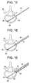
- Figs. 8-16relate to a second expansible implant 101, the elements of which are functionally similar to the corresponding elements of the implant illustrated in Figs. 1-7 . Moreover, the corresponding features in Figs. 8-16 relating to the implant illustrated in Figs. 1-7 include the same reference numerals, respectively, with the addition of the number 100 and therefore will not be described further.
- Implant 101differs from the implant 1 by the absence of the wing portion on the plates 106 and 107, as represented more particularly in Fig. 9 .
- Implant 101includes a deformable parallelogram system 141 on one of the rigid parts 128 or 132 of each of the arms (upper) 122 and (lower) 123.
- the parallelogram systemis represented on rigid part 128 of upper arm 122, connected to the end 120 and the corresponding system on lower arm 123.
- the parallelogram systemsmay be used to ensure displacement of the plates of each of the arms 122 and 123, parallel to longitudinal axis 110 of the implant.
- the rigid part 128 of the arm 122(similarly on corresponding arm 123) is split, as are articulations 131 and 129 (respectively) over the central part 130 and over the end 120 of the implant in order to form a parallelogram which is deformable during displacement of the corresponding plate.
- the articulations of the deformable parallelogram 141may be produced in the same manner as the other articulations 131, 133, 134 of the arm 122, as represented in Figs. 8-16 .
- the disclosed geometryas explained above and represented in Figs. 11-14 , establishes force couples on the various parts 129, 130, 132 of the arm. This allows for the desired displacements when bringing together ends 120 and 121 of the implant 101.
- the rigid part 128 of the armis preferably divided into three longitudinal levers: two lateral levers 142 and a central lever 143, which form two sides of the deformable parallelogram 141.
- the two remaining sides of the parallelogrammay be formed by an extension 144 of the central part of the arm 122, placed in an axis of extension of the central lever 143, and by a double extension 145 of the end 120, extending parallel to the longitudinal axis 110 of the implant and placed in the axis of extension of the two lateral levers 142 (see Fig. 8 ).
- arms 122 and 123may be symmetrical with respect to a plane which is substantially perpendicular to the plane of expansion 102 passing through the longitudinal axis 110 of the implant 101 in order to obtain, during the expansion of the implant, the displacement of the two plates 106 and 107 in a manner parallel to the longitudinal axis 110.
- FIG. 17-29A first example of a method for human bone restoration using an expansible implant will now be described with reference to Figs. 17-29 . It concerns, more particularly, a method for bone restoration of a vertebra via a posterolateral route, with fracture reduction. Accordingly, the method may include one or more (and preferably all) of the following steps.
- the implantpushes though/divides tissues in the interior of the bone so that the bearing surfaces of the implant preferably come into contact with the bone tissue for restoration.
- An expansible implant, expansible (preferably) in a single determined expansion plane 2is introduced into a vertebra 60, the shape of which is to be restored.
- a rod/pin 61e.g., Kirschner pin type
- the pin 61is received in a first dilation tube 65 until an end of the first tube 65 contacts (e.g., maybe supported) the exterior surface of the cortical bone 64 ( Fig. 18 ).
- the first dilation tube 65is received by a second dilation tube 66, until the end of the second tube 66 comes into contact (e.g., supported by) the exterior surface of the cortical bone 64 ( Fig. 19 ).
- the second dilation tubeis further received by a third dilation tube 67, which comes into contact (e.g. is supported) on the exterior surface of the cortical bone 64 ( Fig. 20 ). Teeth 68 on the end of the third dilation tube 67 anchor the tube in the cortical bone 64.
- the first 65 and second 66 dilation tubesare then removed, leaving only the pin 61 surrounded by tube 67, which are separated from one another by tubular spacer 68.
- the proximal cortical bone 64 and cancellous bone 70is then pierced by means of a drill 69 (for example) guided by the pin 61, as represented in Fig. 22 .
- the cancellous boneis pierced as far as the distal third (approximately), then the drill 69 may be withdrawn (the pin 61 may be withdrawn as well).
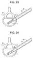
- a proximal end of the implant 1is removably attached to a distal end of a hollow core (preferably) implant carrier 71 which is then introduced into the core of tube 67, as represented in Fig. 23 .
- the implantmay be removably affixed to the implant carrier via threaded engagement (for example).
- a rod 72(see also Fig 33 , reference numeral 3316) having a distal end which includes an engagement means to engage the distal end of the implant (and which may also include an expanded proximal end, larger than a diameter of the rod) may be inserted.
- the engagement means of the rod to the implantmay be via threaded engagement.
- the implant carrier 71includes a handling means 3310 for controlled movement of the rod relative to the implant carrier (for example).
- the handing meansmay comprise a gripping block 3312, having a central bore through which the implant carrier 71 is positioned and is held in place at least rotationally, but preferably rotationally and linearly. In that regard, a proximal end of the gripping member and the proximal end of the implant carrier are preferably flush.
- a handle 3314may be attached to the proximal end of either or both of the gripping member and the implant carrier, but is preferably free to rotate relative thereto in either or both of the clockwise and counterclockwise directions. In still another embodiment of the invention, the handle may not be attached to either or both of the gripping block and implant carrier.
- the handlemay include a center opening which preferably includes internal screw threads of a predetermined thread pitch.
- the rod 3316which is received within the implant carrier, preferably includes external threads corresponding in thread pitch to that of handle 3314.
- a locking device 3311slides relative to the gripping block and may include a pin 3321 which frictionally interferes with the rod 3316, to lock the rod in place (i.e., no rotational movement).
- the threads of the rodare preferably provided at least along a majority of the length rod.
- the rod, implant carrier, gripping block and handlemay be pre-assembled. One would insert the threaded distal end of the rod into an opening in the center of the proximal end of the implant, where it then may be received in the correspondingly threaded portion in the center of the distal end of the implant. The distal end (i.e., the location of the implant) of the assembly of the implant with the implant carrier/handling means may then be inserted into dilation tube 67.
- Fig. 34illustrates another view of the implant carrier, and includes a gauge 3320 which may be used to indicate the amount of expansion of the implant (e.g., a determination on the rotation amount of the rod 3316).
- the gaugemay comprise a window to the rod 3316.
- the portion of the rod that is visiblemay not include threads. Rather, this section of the rod may include markings 3322 which indicate a percentage of expansion. Additional markings 3324 provided adjacent the window allow a user to gauge the percentage of expansion from the relative movement between the two markings.
- Fig. 36is a chart illustrating a no-load expansion of an implant according to one of the embodiments of the invention by the number of turns of the rod for three particular sizes of implants.
- the implantis positioned within the dilation tube and slid down therein, so that it is placed into the interior of the vertebra 60.
- the implantis preferably positioned such that the single expansion plane 2 corresponds to the desired bone restoration plane ( Fig. 24 ).
- the position of the implantmay be verified using any known imaging techniques, including, for example, X-ray and ultrasound.
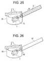
- the handle 3314is then rotated to "pull" the rod away from the implantation area. Since the proximal end of the implant is butted up against the implant carrier, and pulling on the rod causes the distal end of the implant to move toward the proximal end (or visa-versa). This results in the ends of the implant drawing towards each other which opens out the implant. More specifically, opposite plates 6 and 7 are opened out, advantageously forming, respectively, a first 8 and a second 9 support surface in the vertebra 60, which surfaces may be continuous over their length which may be substantially equal to the length of the implant 1 ( Fig. 25 ). In the course of the expansion, control of the reduction of the fracture
- the expansion of the implant in the vertebrais achieved by support under the plates allowing the thrust force to be distributed over the length of the plates under the latter.
- a sufficient length of the platesmay be provided while limiting an excessive dimensioning of the thickness of the latter in order to resist flexion.
- the implant according to some embodiments of the inventionadopt a ratio of a spatial requirement in length (un-expanded) to length of elevated plate which is extremely optimised, allowing a preferable use of the limited intra-osseous spaces with a view to fracture reduction, for example.
- the rod 3316may also include, according to one of the embodiments of the invention, a disengagement means, which may comprise an internal hex on the proximal end 3318 of the rod. This may allow one to disengage the rod from the implant once the implant has been opened out.
- the handlecould be counter-rotated (i.e., rotated such that the rod does not move in a direction away from the implant) such that it travels away from the flush portion of the gripping block and implant carrier, such that it engages the proximal end of the rod.
- a filling material 74is injected around the implant.
- the filling materialmay comprise, for example, an ionic cement, in particular, a phosphocalcic cement, an acrylic cement or a compound of the latter, with a view to filling in and around the implant.
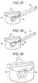
- a needle of the injector 73is slid down tube 67 until the end of the needle reaches the distal orifice 39 of the implant 1 ( Fig. 27 ).
- the filling materialis then injected via the needle.
- Continued injection in a retrograde mannermay be done up to a proximal orifice 64 in cortical bone of the vertebra 60 ( Fig. 28 ).
- the needle of the injectormay then be withdraw from tube 67 ( Fig. 29 ).
- FIG. 30-32A second example of a method for restoration of human bone anatomy, will now be described with references to Figs. 30-32 .
- This examplegenerally concerns a method for bone restoration of a vertebra by a transpedicular route, with fracture reduction.
- the second exampleis similar to the first and differs from the latter by the penetration route of the implant into the vertebra 60, which is now accomplished in a transpedicular manner ( Fig. 30 ) instead of the posterolateral route used in the first method.
- Figs. 30-32only some steps of the second method have been represented in Figs. 30-32 in order to show the different route used for the introduction of the implant 1 into the vertebra.
- elements identical to those of the first method examplehave the same numerical references, and those figures correspond respectively to the steps of Figs. 24 , 25 and 28 of the first method example.
- Concerning the step represented in Fig. 32the latter differs slightly from Fig. 28 by the position of the needle of the injector 73, closer to the distal end of the implant in Fig. 32 .
Landscapes
- Health & Medical Sciences (AREA)
- Orthopedic Medicine & Surgery (AREA)
- Engineering & Computer Science (AREA)
- Biomedical Technology (AREA)
- Life Sciences & Earth Sciences (AREA)
- Transplantation (AREA)
- General Health & Medical Sciences (AREA)
- Veterinary Medicine (AREA)
- Heart & Thoracic Surgery (AREA)
- Public Health (AREA)
- Animal Behavior & Ethology (AREA)
- Neurology (AREA)
- Cardiology (AREA)
- Vascular Medicine (AREA)
- Oral & Maxillofacial Surgery (AREA)
- Surgery (AREA)
- Physical Education & Sports Medicine (AREA)
- Nuclear Medicine, Radiotherapy & Molecular Imaging (AREA)
- Medical Informatics (AREA)
- Molecular Biology (AREA)
- Prostheses (AREA)
- Surgical Instruments (AREA)
- Materials For Medical Uses (AREA)
Description
- The present invention relates to the field of surgery and medical implants and more particularly to devices and methods for restoring human or animal bone anatomy using medical bone implants.
- Various causes can be at the root of bone compression, in particular osteoporosis which causes (for example) natural vertebral compression under the weight of the individual, but also traumas, with the two causes occasionally being combined. Such bone compressions can affect the vertebrae but also concern other bones, such as the radius and the femur, for example.
- Several vertebroplasty techniques are known for effecting a vertebral correction i.e., to restore a vertebra to its original shape, or a shape similar to the latter. For example, one technique includes the introduction of an inflatable balloon into a vertebra, then introducing a fluid under pressure into the balloon in order to force the cortical shell of the vertebra, and in particular the lower and upper vertebral plateaus, to correct the shape of the vertebra under the effect of the pressure. This technique is known by as kyphoplasty. Once the osseous cortical shell has been corrected, the balloon is then deflated, and withdrawn from the vertebra in order to be able to inject a cement into the cortical shell which is intended to impart, sufficient mechanical resistance for the correction to have a significant duration in time.
- A notable disadvantage of the kyphoplasty method resides in its numerous manipulations, in particular inflation, and in the necessity to withdraw the balloon from the patient's body. Furthermore, the expansion of a balloon is poorly controlled because the balloon's volume is multi-directional, which often causes a large pressure to be placed on the cortical shell in unsuitable directions. Such large pressures risk bursting of the cortical shell and, in particular, the lateral part of the cortical shell connecting the lower and upper plateaus of a vertebra.
- Other vertebral implants exist which are intended to fill a cavity in a vertebra. An example of an insertion tool for inserting an expandable interbody cage can be seen in
EP 1,107,711 . Such implants, however, generally adopt a radial expansion principle obtained by formation of a plurality of points which stand normally to the longitudinal axis of the implant under the effect of contraction of the latter. Such implants impose too high a pressure on individual points which may pierce the material on which the points support. Furthermore, similar to kyphoplasty, very high pressure can cause bursting of the tissues or organ walls, such as the cortical shell, for example. Furthermore, the radial expansion of some implants does not allow a particular expansion direction to be favoured. - The invention is defined in
claim 1. Preferred embodiments are defined in the dependent claims. - Still other features, advantages, embodiments and objects of the present invention will become even more clear with reference to the attached drawings, a brief description of which is set out below, and the following detailed description.
Fig. 1A illustrates a perspective view of an embodiment of an expansible implant in a resting position.Fig. 1B illustrates the example ofFig. 1A , in opened-out/expanded position.Fig. 2A illustrates a side view of another embodiment of an expansible implant in a resting position.Fig. 2B illustrates the example ofFig. 2A , in opened-out/expanded position.Fig. 3 illustrates a lateral view of the example according toFig. 1A .Fig. 4 illustrates a view in section according to the line I-I ofFig. 3 .Fig. 5 illustrates a view in section according to the line II-II ofFig. 3 .Fig. 6 represents an end view according to F of the example according toFig. 1A .Fig. 7 illustrates a view from above of the example according toFig. 1A .Fig. 8 illustrates a perspective view of a second embodiment of an expansible implant in a resting position.Fig. 9 illustrates the example ofFig. 8 , in opened-out position.Fig. 10 illustrates a lateral view of the example according toFig. 8 .Fig. 11 illustrates a view in section according to the line III-III ofFig. 10 .Fig. 12 illustrates a view in section according to the line IV-IV ofFig. 10 .Fig. 13 illustrates a view in section according to the line V-V ofFig. 10 .Fig. 14 illustrates a view in section according to the line NI-NI ofFig. 10 .Fig. 15 illustrates an end view according to G of the example according toFig. 8 .Fig. 16 illustrates a view from above of the example according toFig. 8 .Figs. 17-29 illustrate schematically, the different steps of an embodiment of a method for bone restoration.Figs. 30-32 illustrate schematically, steps of another method for bone restorationFig. 33 illustrates a perspective view of an implant carrier device for inserting an implant into the bone of a patient according to the present invention.Fig. 34 illustrates a top view of the implant carrier device ofFig. 33 .Fig. 35 illustrates an expansion gauge for the implant carrier shown inFigs. 33 and34 .Fig. 36 illustrates a chart with expansion values for implants according to the disclosed embodiments using the implant carrier shown inFigs. 33 and34 .Fig. 37 illustrates the use of a pair of implants.- The
expansible implant 1 represented inFigs, 1A to 7 (as well as other embodiments) may include one or more of the following: - a single
determined expansion plane 2, which may be intrinsic to the implant, - means 3 for positioning the expansible implant in the bone allowing the expansion plane to correspond with a bone restoration plane,
- means 4 for opening out the expansible implant in the
single expansion plane 2, - means 5 for controlling a determined expansion value, between a minimum thickness A of the implant before any expansion of the latter and a maximum thickness B of the implant after its maximum expansion, and
- a first 6 and a second 7 opposite plate which are able to form respectively a first 8 and a second 9 support surface in the bone intended to be moved apart one from the other along the
single expansion plane 2 during expansion of theimplant 1. - As shown in
Figs. 1A and 1B ,implant 1 may include a cylindrical shape with a transverse circular exterior section, and can be manufactured of biocompatible material, (for example titanium) into a tubular body using lathe, laser, and/or electro-erosion manufacturing techniques (cast manufacturing may also be used). Theimplant 1 may also include afirst end 20 and asecond end 21, each respectfully adopting the shape of a transverse section of the tubular body. The ends are preferably intended to be brought towards one another to allow the opening-out/expansion of the implant, as represented inFigs. 1B and2B . - Accordingly, the two ends 20, 21 are connected to each other by a first (upper) 22 and second (lower) 23 rectilinear arms, which are parallel when the implant is not opened-out. The arms may be formed longitudinally in the tubular body -- i.e., able to be folded under the first 6 and second 7 opposite plates upon ends 20 and 21 being brought towards one another, which also results in the distancing of first 6 and second 7 opposite plates from the
longitudinal axis 10 of the tubular body. Figs. 2A-2C illustrate an implant which is similar to the one disclosed inFigs. 1A and 1B , but with an additional set of supports (e.g., a four bar linkage). More specifically, the implant inFigs. 2A-2B includessupports plates - As represented in
Figs. 4-5 , in order forarms longitudinal axis 10 of the tubular body), thearms arms transverse recess 40 of the tubular body, traversing the tubular body throughout, and extending over the length of the tubular body between the two ends 20 and 21 of theimplant 1. As represented inFig. 5 , the arms, 22, 23 connecting the two ends 20 and 21, respectively adopt a transverse section bounded by acircular arc 26 of the exterior surface of the tubular body.Chord 27 defines thecircular arc 26 and may be included in thewall 25 to formrecess 40. Therecess 40 may be symmetrical with respect to thelongitudinal axis 10. - Each
arm ends rigid part 28 is connected at one end to end 20 by means of anarticulation 29. The other end ofrigid part 28 is connected to a first end of a second adjacent centralrigid part 30 by means of anarticulation 31. The secondrigid part 30 may be connected at a second end to the thirdrigid part 32 by means of anarticulation 33. The other end of the thirdrigid part 32 may be connected to end 21 by means of anarticulation 34. Preferably, thearticulations expansion plane 2. Preferably,articulations Figs. 1A-3 (see also, e.g.,reference numerals 5 and 81). - Each
arm rigid part 30 moves away from thelongitudinal axis 10 of the implant pushed by the two adjacentrigid parts Fig. 3 , in order to initiate the movement of the arm in the correct direction when the ends 20 and 21 are brought towards the other, it is preferable to establish a suitable rotation couple of the various parts of the arm. - Accordingly, the ends of
rigid parts upper arm 22 may be articulated with ends 20 and 21, respectively, via a material web formed on the rigid parts. Other ends ofrigid parts rigid part 30 via a material web formed onrigid parts rigid parts ends longitudinal axis 10 of the implant. This displacement tends to make therigid part 32 pivot towards the exterior of the implant as a result of moving the centralrigid part 30 away from thelongitudinal axis 10. - The
lower arm 23 may be constructed in a similar manner as the upper arm and is preferably symmetrical to theupper arm 22 with respect to a plane which is perpendicular to theexpansion plane 2 passing through thelongitudinal axis 10. - Thus, the articulations between of the upper 22 and lower 23 arms and corresponding rigid parts are preferably formed by weakened zones produced by
grooves 81. The grooves define a thin web of material (i.e., the thinness of the material at 31, 33) forming the tubular body, the thickness of which may be determined by the depth of the grooves 81 (as represented in the figures) in order to allow plastic deformation of the material without breaking. Specifically, therigid parts upper arm 22, and their symmetrical ones on thelower arm 23, can adopt a position, termed extreme expansion, in which the intended rigid parts are perpendicular to thelongitudinal axis 10 of theimplant 1 upon theends grooves 81 are preferably predetermined to allow a clearance of the parts of the upper and lower arms and also to impart a suitable radius of curvature to the webs in order to ensure plastic deformation without rupture of the material. - The first 6 and second 7 opposite plates may be formed in the upper 22 and lower 23 arms. With respect to the
upper arm 22, for example,plate 6 may be formed by the centralrigid part 30 and by material extensions (rigid parts 28 and 32) extending out both sides thereof. In order to produce therigid plate 6,rigid parts upper arm 22 using a pair oftransverse slots Figs. 3-4 ). Articulations 31 and 33 andrigid parts FIG 1B ) for the first 6 plate. The same applies to thesecond plate 7 by symmetry. - Hence, according to the illustrated example, the first 6 and second 7 plates may comprise respectively a first 16, 18 and a second 17, 19 cantilever wing, the respective attachment zones of which are situated at the level of the first 12, 14 and second 13, 15 supports. As represented in
Figs. 1A-B , the first 16, 18 and second 17, 19 cantilever wings may include a length corresponding substantially to the maximum displacement value of one of the first 6 or second 7 plates in thesingle expansion plane 2. - The first 6 and second 7 plates form first 8 and second 9 support surfaces, respectively, each having a length which may be substantially equal to the length of the implant and which may be displaced perpendicularly to the
longitudinal axis 10 during expansion. According to one embodiment of the invention, since theimplant 1 is formed in a tubular body, the first 6 and second 7 plates form, respectively, curved support surfaces, which are preferably parallel to thelongitudinal axis 10. - The
means 3 for positioning the expansible implant in a bone to enable theexpansion plane 2 to correspond with a bone restoration plane, may include an engagement means which allows for an angular orientation of the implant aboutlongitudinal axis 10. For example, such means may includeflat surfaces end 20, which may allow for rotational engagement of theimplant 1. Themeans 4 for opening out the expansible implant in asingle expansion plane 2, may includerigid parts upper arm 22 and the corresponding symmetrical rigid parts on thelower arm 23, allowing opening out of the first 6 and second 7 plates. - An implant carrier 71 (see
Fig. 23 ) may be used to allow theends implant carrier 71, by supportingend 20 of the implant, for example, allows theend 21 to be pulled towardend 20, or vice-versa (e.g., end 21 being supported and end 20 being pushed toward end 21). To that end, thedistal end 21, for example, comprises an opening/distal orifice 39 threaded along thelongitudinal axis 10 in order to allow the engagement of theimplant carrier 71, which includes a corresponding threaded portion. Theproximal end 20 may include abore 80 along thelongitudinal axis 10 in order to allow the passage of a core of theimplant carrier 71 to pass to thedistal end 21. - A control means may be provided by the implant carrier which may include a millimetric control means for bringing ends 20 and 21 together, preferably by means of screw-thread engagement, allowing the expansion to be stopped at any moment as a function of requirements. On the other hand, the control means provided by the articulations of the
arms - The expansion of the
plates plates plates plates plates supports Figs. 1A-2B ), opening out the implant will forceplates Figs. 1A-2B , this would result thatplates end 21 to be further apart one another then atend 20. As one of ordinary skill in the art will appreciate, depending upon the configuration, only one respective support need be lengthened/shortened, in order to obtain a particular angle. - Similarly, as shown in
Figs. 2A-2C , when the four barlinkage comprising supports Fig. 2C ). By modifying the lengths of LI and L2, the four bar linkage will not result in a parallelogram upon expansion, but rather an angle betweenplate Figs. 8-16 relate to a secondexpansible implant 101, the elements of which are functionally similar to the corresponding elements of the implant illustrated inFigs. 1-7 . Moreover, the corresponding features inFigs. 8-16 relating to the implant illustrated inFigs. 1-7 include the same reference numerals, respectively, with the addition of thenumber 100 and therefore will not be described further.- The represented
implant 101 differs from theimplant 1 by the absence of the wing portion on theplates Fig. 9 .Implant 101 includes adeformable parallelogram system 141 on one of therigid parts rigid part 128 ofupper arm 122, connected to theend 120 and the corresponding system onlower arm 123. The parallelogram systems may be used to ensure displacement of the plates of each of thearms longitudinal axis 110 of the implant. As represented in the figures, therigid part 128 of the arm 122 (similarly on corresponding arm 123) is split, as arearticulations 131 and 129 (respectively) over thecentral part 130 and over theend 120 of the implant in order to form a parallelogram which is deformable during displacement of the corresponding plate. - The articulations of the
deformable parallelogram 141 may be produced in the same manner as theother articulations arm 122, as represented inFigs. 8-16 . The disclosed geometry as explained above and represented inFigs. 11-14 , establishes force couples on thevarious parts implant 101. - In order to obtain a
deformable parallelogram 141, therigid part 128 of the arm is preferably divided into three longitudinal levers: twolateral levers 142 and acentral lever 143, which form two sides of thedeformable parallelogram 141. The two remaining sides of the parallelogram may be formed by anextension 144 of the central part of thearm 122, placed in an axis of extension of thecentral lever 143, and by adouble extension 145 of theend 120, extending parallel to thelongitudinal axis 110 of the implant and placed in the axis of extension of the two lateral levers 142 (seeFig. 8 ). - It is worth noting that
arms expansion 102 passing through thelongitudinal axis 110 of theimplant 101 in order to obtain, during the expansion of the implant, the displacement of the twoplates longitudinal axis 110. - A first example of a method for human bone restoration using an expansible implant will now be described with reference to
Figs. 17-29 . It concerns, more particularly, a method for bone restoration of a vertebra via a posterolateral route, with fracture reduction. Accordingly, the method may include one or more (and preferably all) of the following steps. One of skill in the art will appreciate that the implant pushes though/divides tissues in the interior of the bone so that the bearing surfaces of the implant preferably come into contact with the bone tissue for restoration. - An expansible implant, expansible (preferably) in a single determined expansion plane 2 (intrinsic to the implant) is introduced into a
vertebra 60, the shape of which is to be restored. To effect this operation, a rod/pin 61 (e.g., Kirschner pin type) is placed percutaneously via the posterolateral route so that the threadedend 62 can be affixed (e.g., screwed) into thecortical bone 63 opposite thecortical bone 64 which is traversed by the pin (Fig. 17 ). Thepin 61 is received in afirst dilation tube 65 until an end of thefirst tube 65 contacts (e.g., maybe supported) the exterior surface of the cortical bone 64 (Fig. 18 ). - The
first dilation tube 65 is received by asecond dilation tube 66, until the end of thesecond tube 66 comes into contact (e.g., supported by) the exterior surface of the cortical bone 64 (Fig. 19 ). The second dilation tube is further received by athird dilation tube 67, which comes into contact (e.g. is supported) on the exterior surface of the cortical bone 64 (Fig. 20 ).Teeth 68 on the end of thethird dilation tube 67 anchor the tube in thecortical bone 64. - The first 65 and second 66 dilation tubes, as shown in
Fig. 21 , are then removed, leaving only thepin 61 surrounded bytube 67, which are separated from one another bytubular spacer 68. The proximalcortical bone 64 andcancellous bone 70 is then pierced by means of a drill 69 (for example) guided by thepin 61, as represented inFig. 22 . In one example, the cancellous bone is pierced as far as the distal third (approximately), then thedrill 69 may be withdrawn (thepin 61 may be withdrawn as well). - A proximal end of the
implant 1 is removably attached to a distal end of a hollow core (preferably)implant carrier 71 which is then introduced into the core oftube 67, as represented inFig. 23 . The implant may be removably affixed to the implant carrier via threaded engagement (for example). Within the core of theimplant carrier 71, a rod 72 (see alsoFig 33 , reference numeral 3316) having a distal end which includes an engagement means to engage the distal end of the implant (and which may also include an expanded proximal end, larger than a diameter of the rod) may be inserted. Similar to the affixation of the implant to the implant carrier, the engagement means of the rod to the implant may be via threaded engagement. - The
implant carrier 71, as shown inFig. 33 , includes a handling means 3310 for controlled movement of the rod relative to the implant carrier (for example). The handing means may comprise agripping block 3312, having a central bore through which theimplant carrier 71 is positioned and is held in place at least rotationally, but preferably rotationally and linearly. In that regard, a proximal end of the gripping member and the proximal end of the implant carrier are preferably flush. Ahandle 3314, according to one embodiment of the invention, may be attached to the proximal end of either or both of the gripping member and the implant carrier, but is preferably free to rotate relative thereto in either or both of the clockwise and counterclockwise directions. In still another embodiment of the invention, the handle may not be attached to either or both of the gripping block and implant carrier. The handle may include a center opening which preferably includes internal screw threads of a predetermined thread pitch. - The
rod 3316, which is received within the implant carrier, preferably includes external threads corresponding in thread pitch to that ofhandle 3314. A locking device 3311 slides relative to the gripping block and may include apin 3321 which frictionally interferes with therod 3316, to lock the rod in place (i.e., no rotational movement). - The threads of the rod are preferably provided at least along a majority of the length rod. According to one embodiment of the invention, the rod, implant carrier, gripping block and handle may be pre-assembled. One would insert the threaded distal end of the rod into an opening in the center of the proximal end of the implant, where it then may be received in the correspondingly threaded portion in the center of the distal end of the implant. The distal end (i.e., the location of the implant) of the assembly of the implant with the implant carrier/handling means may then be inserted into
dilation tube 67. Fig. 34 illustrates another view of the implant carrier, and includes agauge 3320 which may be used to indicate the amount of expansion of the implant (e.g., a determination on the rotation amount of the rod 3316). The gauge may comprise a window to therod 3316. As show inFig. 35 , according to one embodiment of the invention, the portion of the rod that is visible may not include threads. Rather, this section of the rod may includemarkings 3322 which indicate a percentage of expansion.Additional markings 3324 provided adjacent the window allow a user to gauge the percentage of expansion from the relative movement between the two markings.- Depending upon the predetermined thread pitch and direction of the thread of the
rod 3316, rotation of the handle moves therod 3316 relative to the implant carrier linearly in a direction. Preferably, the threads are provided on the rod such that clockwise rotation of the handle moves the rod outward away from an area in which the implant is to expand (the implantation area). For example, for an M5 thread, a pitch of 0.8 mm may be used. However, one of skill in the art will appreciate that a thread pitch of between about 0.5 mm and about 1.0 mm (for example) may be used.Fig. 36 is a chart illustrating a no-load expansion of an implant according to one of the embodiments of the invention by the number of turns of the rod for three particular sizes of implants. - Accordingly, in view of the a bove embodiment, once the implant is positioned within the dilation tube and slid down therein, so that it is placed into the interior of the
vertebra 60. The implant is preferably positioned such that thesingle expansion plane 2 corresponds to the desired bone restoration plane (Fig. 24 ). The position of the implant may be verified using any known imaging techniques, including, for example, X-ray and ultrasound. - The
handle 3314 is then rotated to "pull" the rod away from the implantation area. Since the proximal end of the implant is butted up against the implant carrier, and pulling on the rod causes the distal end of the implant to move toward the proximal end (or visa-versa). This results in the ends of the implant drawing towards each other which opens out the implant. More specifically,opposite plates vertebra 60, which surfaces may be continuous over their length which may be substantially equal to the length of the implant 1 (Fig. 25 ). In the course of the expansion, control of the reduction of the fracture - Accordingly, the expansion of the implant in the vertebra is achieved by support under the plates allowing the thrust force to be distributed over the length of the plates under the latter. Thus a sufficient length of the plates may be provided while limiting an excessive dimensioning of the thickness of the latter in order to resist flexion. It will be appreciated by those of ordinary skill in the art that the implant according to some embodiments of the invention adopt a ratio of a spatial requirement in length (un-expanded) to length of elevated plate which is extremely optimised, allowing a preferable use of the limited intra-osseous spaces with a view to fracture reduction, for example.
- The
rod 3316 may also include, according to one of the embodiments of the invention, a disengagement means, which may comprise an internal hex on theproximal end 3318 of the rod. This may allow one to disengage the rod from the implant once the implant has been opened out. Alternatively, where the handle is not attached to the gripping block and/or implant carrier, the handle could be counter-rotated (i.e., rotated such that the rod does not move in a direction away from the implant) such that it travels away from the flush portion of the gripping block and implant carrier, such that it engages the proximal end of the rod. Further counter-rotation of the handle (after opening out of the implant) causes the rod to rotate in the same counter-rotation as the handle, thereby causing the rod to disengage from the implant. Depending upon the determined thread pitch, such disengagement can occur in any number of rotations (e.g., less or more than one rotation). See alsoFig. 26 - Preferably, after the rod has been removed, a filling
material 74 is injected around the implant. The filling material may comprise, for example, an ionic cement, in particular, a phosphocalcic cement, an acrylic cement or a compound of the latter, with a view to filling in and around the implant. To accomplish this, a needle of theinjector 73 is slid downtube 67 until the end of the needle reaches thedistal orifice 39 of the implant 1 (Fig. 27 ). The filling material is then injected via the needle. Continued injection in a retrograde manner may be done up to aproximal orifice 64 in cortical bone of the vertebra 60 (Fig. 28 ). The needle of the injector may then be withdraw from tube 67 (Fig. 29 ). - A second example of a method for restoration of human bone anatomy, will now be described with references to
Figs. 30-32 . This example generally concerns a method for bone restoration of a vertebra by a transpedicular route, with fracture reduction. - The second example is similar to the first and differs from the latter by the penetration route of the implant into the
vertebra 60, which is now accomplished in a transpedicular manner (Fig. 30 ) instead of the posterolateral route used in the first method. As a result, only some steps of the second method have been represented inFigs. 30-32 in order to show the different route used for the introduction of theimplant 1 into the vertebra. ForFigs. 30 to 32 , elements identical to those of the first method example have the same numerical references, and those figures correspond respectively to the steps ofFigs. 24 ,25 and28 of the first method example. Concerning the step represented inFig. 32 , the latter differs slightly fromFig. 28 by the position of the needle of theinjector 73, closer to the distal end of the implant inFig. 32 . - It will thus be seen that the invention attains the objects made apparent from the preceding description. Since certain changes may be made without departing from the scope of the present invention, it is intended that all matter contained in the above description or shown in the accompanying drawings be interpreted as illustrative and not in a literal sense (and thus, not limiting). Practitioners of the art will realize that the method, device and system configurations depicted and described herein are examples of multiple possible system configurations that fall within the scope of the current invention.
Claims (18)
- A medical insertion device (3310) for inserting an expansible implant (1) into a patient, comprising:a gripping portion (3312), having a central bore;a first tube (71) housed in the central bore;a rod (3316) housed in the first tube having a distal end for receiving an implant for insertion into the patient;a handle (3314) attached to the gripping portion;
characterised in that the medical insertion device comprisesa gauge (3320) for determining an expansion of the implant (1). - The device according to claim1, wherein a proximal end of the gripping portion (3312) and a proximal end of the first tube (71) are flush.
- The device according to claim1 or claim2, wherein the handle (3314) is attached to the proximal end of either or both of the gripping portion (3312) and the first tube (71).
- The device according to any preceding claim, wherein the handle (3314) is free to rotate relative to the gripping portion (3312) and/or the first tube (71).
- The device according to any preceding claim, wherein the rod (3316) comprises a threaded rod and wherein the handle (3314) includes an opening having screw threads corresponding in thread pitch to a thread pitch of the threaded rod.
- The device according to any preceding claim, wherein the gauge (3320) comprises an opening in the gripping portion (3312) for viewing a portion of the rod (3316).
- The device according to claim6, wherein the gauge (3320) further comprises first markings positioned adjacent the window (3324) associated with second markings (3322) provided on a portion of the rod (3316) displayed in the window, wherein rotation of the rod (3316) results in relative movement between the first (3324) and second (3322) markings.
- The device according to any preceding claim, further comprising a locking device (3321) to substantially stop the rod (3316) from rotation.
- The device according to any preceding claim, wherein the distal end of the rod (3316) includes engagement means for engagement with the distal end of the implant (1).
- The device according to claim9, wherein the engagement means comprises threaded engagement.
- The device according to any preceding claim, wherein the rod (3316) traverses through the handle (3314).
- The device according to any preceding claim, wherein the proximal end of the rod includes disengagement means (3318) enabling the rod to either disengage from the implant (1) or disengage from the first tube (71).
- A method for opening out an expansible implant (1) with a medical insertion device (3310), the medical insertion devicecharacterised by comprising:a gripping portion (3312), having a central bore;a first tube (71) housed in the central bore;a rod (3316) housed in the first tube having a distal end for receiving an implant for insertion into the patient;a handle (3314) attached to the gripping portion;and a gauge (3320) for determining an expansion of the implant (1);the method comprising:attaching the distal end of the rod (3316) to the implant (1) and the proximal end of the implant (1) to the distal end of the first tube (71);and rotating the handle (3314) to linearly move the rod (3316) relative to the first tube (71) in the proximal direction, so as to pull the rod (3316) away from the implant, wherein because the proximal end of the implant (1) is positioned against the first tube (71), the movement causes the distal end of the implant (1) to move toward the proximal end of the implant (1) resulting in the ends of the implant (1) drawing towards each other thereby opening out the implant (1).
- The method according to claim13, wherein the rod (3316) includes engagement means for engagement with an implant (1).
- The method according to claim13 or claim14, wherein the rod (3316) comprises a threaded rod, and attaching the distal end of the rod (3316) to the distal end of the implant (1) comprises rotating the handle (3314) in a first direction.
- The method according to claim15, further comprises detaching the rod (3316) from the distal end of the implant (1) by counter rotation of the handle (3314) in a second direction.
- The method according to claim14, further comprising determining expansion of the implant (1) by means of the gauge (3320).
- The method according to anyone of claims13 to17, wherein the medical insertion device further comprises a locking device (3321) to substantially stop the rod (3316) from rotation.
Applications Claiming Priority (3)
| Application Number | Priority Date | Filing Date | Title |
|---|---|---|---|
| FR0406211AFR2871366A1 (en) | 2004-06-09 | 2004-06-09 | PROSTHETIC EXPANSIBLE BONE IMPLANT |
| US10/951,766US20050278036A1 (en) | 2004-06-09 | 2004-09-29 | Method for restoration of human or animal bone anatomy, and expansible prosthetic implant allowing implementation of this method |
| EP05780621.8AEP1778136B1 (en) | 2004-06-09 | 2005-06-08 | Apparatuses for bone restoration |
Related Parent Applications (2)
| Application Number | Title | Priority Date | Filing Date |
|---|---|---|---|
| EP05780621.8ADivisionEP1778136B1 (en) | 2004-06-09 | 2005-06-08 | Apparatuses for bone restoration |
| EP05780621.8Division | 2005-06-08 |
Publications (2)
| Publication Number | Publication Date |
|---|---|
| EP2572680A1 EP2572680A1 (en) | 2013-03-27 |
| EP2572680B1true EP2572680B1 (en) | 2016-04-27 |
Family
ID=34945793
Family Applications (2)
| Application Number | Title | Priority Date | Filing Date |
|---|---|---|---|
| EP12191848.6AExpired - LifetimeEP2572680B1 (en) | 2004-06-09 | 2005-06-08 | Apparatuses for bone restoration |
| EP05780621.8AExpired - LifetimeEP1778136B1 (en) | 2004-06-09 | 2005-06-08 | Apparatuses for bone restoration |
Family Applications After (1)
| Application Number | Title | Priority Date | Filing Date |
|---|---|---|---|
| EP05780621.8AExpired - LifetimeEP1778136B1 (en) | 2004-06-09 | 2005-06-08 | Apparatuses for bone restoration |
Country Status (12)
| Country | Link |
|---|---|
| US (6) | US20050278036A1 (en) |
| EP (2) | EP2572680B1 (en) |
| JP (3) | JP4620120B2 (en) |
| KR (1) | KR101206552B1 (en) |
| CN (2) | CN101031259A (en) |
| AU (1) | AU2005251536B2 (en) |
| CA (1) | CA2567274C (en) |
| ES (2) | ES2576291T3 (en) |
| FR (2) | FR2871366A1 (en) |
| MX (2) | MXPA06014196A (en) |
| PL (1) | PL1778136T4 (en) |
| WO (1) | WO2005120400A2 (en) |
Families Citing this family (349)
| Publication number | Priority date | Publication date | Assignee | Title |
|---|---|---|---|---|
| US7959652B2 (en)* | 2005-04-18 | 2011-06-14 | Kyphon Sarl | Interspinous process implant having deployable wings and method of implantation |
| US6068630A (en)* | 1997-01-02 | 2000-05-30 | St. Francis Medical Technologies, Inc. | Spine distraction implant |
| US8128661B2 (en)* | 1997-01-02 | 2012-03-06 | Kyphon Sarl | Interspinous process distraction system and method with positionable wing and method |
| US7201751B2 (en) | 1997-01-02 | 2007-04-10 | St. Francis Medical Technologies, Inc. | Supplemental spine fixation device |
| US20080086212A1 (en)* | 1997-01-02 | 2008-04-10 | St. Francis Medical Technologies, Inc. | Spine distraction implant |
| US6695842B2 (en)* | 1997-10-27 | 2004-02-24 | St. Francis Medical Technologies, Inc. | Interspinous process distraction system and method with positionable wing and method |
| US20080039859A1 (en)* | 1997-01-02 | 2008-02-14 | Zucherman James F | Spine distraction implant and method |
| US7306628B2 (en)* | 2002-10-29 | 2007-12-11 | St. Francis Medical Technologies | Interspinous process apparatus and method with a selectably expandable spacer |
| CA2363254C (en) | 1999-03-07 | 2009-05-05 | Discure Ltd. | Method and apparatus for computerized surgery |
| FR2828398B1 (en)* | 2001-08-08 | 2003-09-19 | Jean Taylor | VERTEBRA STABILIZATION ASSEMBLY |
| US7097665B2 (en)* | 2003-01-16 | 2006-08-29 | Synecor, Llc | Positioning tools and methods for implanting medical devices |
| DE10154163A1 (en)* | 2001-11-03 | 2003-05-22 | Advanced Med Tech | Device for straightening and stabilizing the spine |
| US8317798B2 (en)* | 2002-06-25 | 2012-11-27 | Warsaw Orthopedic | Minimally invasive expanding spacer and method |
| US6793678B2 (en) | 2002-06-27 | 2004-09-21 | Depuy Acromed, Inc. | Prosthetic intervertebral motion disc having dampening |
| CN100584294C (en)* | 2002-08-27 | 2010-01-27 | 华沙整形外科股份有限公司 | System for intravertebral reduction |
| FR2844179B1 (en)* | 2002-09-10 | 2004-12-03 | Jean Taylor | POSTERIOR VERTEBRAL SUPPORT KIT |
| US7931674B2 (en)* | 2005-03-21 | 2011-04-26 | Kyphon Sarl | Interspinous process implant having deployable wing and method of implantation |
| US20080021468A1 (en)* | 2002-10-29 | 2008-01-24 | Zucherman James F | Interspinous process implants and methods of use |
| US20060264939A1 (en)* | 2003-05-22 | 2006-11-23 | St. Francis Medical Technologies, Inc. | Interspinous process implant with slide-in distraction piece and method of implantation |
| US7549999B2 (en)* | 2003-05-22 | 2009-06-23 | Kyphon Sarl | Interspinous process distraction implant and method of implantation |
| US8147548B2 (en) | 2005-03-21 | 2012-04-03 | Kyphon Sarl | Interspinous process implant having a thread-shaped wing and method of implantation |
| US8048117B2 (en) | 2003-05-22 | 2011-11-01 | Kyphon Sarl | Interspinous process implant and method of implantation |
| US8070778B2 (en)* | 2003-05-22 | 2011-12-06 | Kyphon Sarl | Interspinous process implant with slide-in distraction piece and method of implantation |
| AU2004212942A1 (en) | 2003-02-14 | 2004-09-02 | Depuy Spine, Inc. | In-situ formed intervertebral fusion device |
| US20040267367A1 (en) | 2003-06-30 | 2004-12-30 | Depuy Acromed, Inc | Intervertebral implant with conformable endplate |
| WO2005027734A2 (en)* | 2003-09-19 | 2005-03-31 | Synecor, Llc | Method and apparatus for treating diseased or fractured bone |
| US8636802B2 (en) | 2004-03-06 | 2014-01-28 | DePuy Synthes Products, LLC | Dynamized interspinal implant |
| US7585316B2 (en)* | 2004-05-21 | 2009-09-08 | Warsaw Orthopedic, Inc. | Interspinous spacer |
| FR2871366A1 (en) | 2004-06-09 | 2005-12-16 | Ceravic Soc Par Actions Simpli | PROSTHETIC EXPANSIBLE BONE IMPLANT |
| US8236029B2 (en) | 2004-08-11 | 2012-08-07 | Nlt Spine Ltd. | Devices for introduction into a body via a substantially straight conduit to for a predefined curved configuration, and methods employing such devices |
| WO2006034436A2 (en)* | 2004-09-21 | 2006-03-30 | Stout Medical Group, L.P. | Expandable support device and method of use |
| US8152837B2 (en) | 2004-10-20 | 2012-04-10 | The Board Of Trustees Of The Leland Stanford Junior University | Systems and methods for posterior dynamic stabilization of the spine |
| US8167944B2 (en) | 2004-10-20 | 2012-05-01 | The Board Of Trustees Of The Leland Stanford Junior University | Systems and methods for posterior dynamic stabilization of the spine |
| US9023084B2 (en) | 2004-10-20 | 2015-05-05 | The Board Of Trustees Of The Leland Stanford Junior University | Systems and methods for stabilizing the motion or adjusting the position of the spine |
| US8317864B2 (en) | 2004-10-20 | 2012-11-27 | The Board Of Trustees Of The Leland Stanford Junior University | Systems and methods for posterior dynamic stabilization of the spine |
| US8409282B2 (en) | 2004-10-20 | 2013-04-02 | Vertiflex, Inc. | Systems and methods for posterior dynamic stabilization of the spine |
| US7763074B2 (en) | 2004-10-20 | 2010-07-27 | The Board Of Trustees Of The Leland Stanford Junior University | Systems and methods for posterior dynamic stabilization of the spine |
| US9161783B2 (en) | 2004-10-20 | 2015-10-20 | Vertiflex, Inc. | Interspinous spacer |
| US8128662B2 (en) | 2004-10-20 | 2012-03-06 | Vertiflex, Inc. | Minimally invasive tooling for delivery of interspinous spacer |
| US8425559B2 (en) | 2004-10-20 | 2013-04-23 | Vertiflex, Inc. | Systems and methods for posterior dynamic stabilization of the spine |
| US8273108B2 (en) | 2004-10-20 | 2012-09-25 | Vertiflex, Inc. | Interspinous spacer |
| US8123807B2 (en)* | 2004-10-20 | 2012-02-28 | Vertiflex, Inc. | Systems and methods for posterior dynamic stabilization of the spine |
| US9119680B2 (en) | 2004-10-20 | 2015-09-01 | Vertiflex, Inc. | Interspinous spacer |
| US8597360B2 (en) | 2004-11-03 | 2013-12-03 | Neuropro Technologies, Inc. | Bone fusion device |
| EP2219538B1 (en) | 2004-12-06 | 2022-07-06 | Vertiflex, Inc. | Spacer insertion instrument |
| US8100943B2 (en) | 2005-02-17 | 2012-01-24 | Kyphon Sarl | Percutaneous spinal implants and methods |
| US7988709B2 (en)* | 2005-02-17 | 2011-08-02 | Kyphon Sarl | Percutaneous spinal implants and methods |
| US20070055237A1 (en)* | 2005-02-17 | 2007-03-08 | Edidin Avram A | Percutaneous spinal implants and methods |
| US8029567B2 (en)* | 2005-02-17 | 2011-10-04 | Kyphon Sarl | Percutaneous spinal implants and methods |
| US20080039944A1 (en)* | 2005-02-17 | 2008-02-14 | Malandain Hugues F | Percutaneous Spinal Implants and Methods |
| US20080288078A1 (en)* | 2005-02-17 | 2008-11-20 | Kohm Andrew C | Percutaneous spinal implants and methods |
| US8034080B2 (en) | 2005-02-17 | 2011-10-11 | Kyphon Sarl | Percutaneous spinal implants and methods |
| US20060184248A1 (en)* | 2005-02-17 | 2006-08-17 | Edidin Avram A | Percutaneous spinal implants and methods |
| US8157841B2 (en)* | 2005-02-17 | 2012-04-17 | Kyphon Sarl | Percutaneous spinal implants and methods |
| US8038698B2 (en)* | 2005-02-17 | 2011-10-18 | Kphon Sarl | Percutaneous spinal implants and methods |
| US20070276372A1 (en)* | 2005-02-17 | 2007-11-29 | Malandain Hugues F | Percutaneous Spinal Implants and Methods |
| US20070276493A1 (en) | 2005-02-17 | 2007-11-29 | Malandain Hugues F | Percutaneous spinal implants and methods |
| US8007521B2 (en)* | 2005-02-17 | 2011-08-30 | Kyphon Sarl | Percutaneous spinal implants and methods |
| US8097018B2 (en)* | 2005-02-17 | 2012-01-17 | Kyphon Sarl | Percutaneous spinal implants and methods |
| US7998174B2 (en) | 2005-02-17 | 2011-08-16 | Kyphon Sarl | Percutaneous spinal implants and methods |
| US8096994B2 (en) | 2005-02-17 | 2012-01-17 | Kyphon Sarl | Percutaneous spinal implants and methods |
| US8057513B2 (en)* | 2005-02-17 | 2011-11-15 | Kyphon Sarl | Percutaneous spinal implants and methods |
| US20060241757A1 (en)* | 2005-03-31 | 2006-10-26 | Sdgi Holdings, Inc. | Intervertebral prosthetic device for spinal stabilization and method of manufacturing same |
| US8940048B2 (en) | 2005-03-31 | 2015-01-27 | Life Spine, Inc. | Expandable spinal interbody and intravertebral body devices |
| US9034041B2 (en)* | 2005-03-31 | 2015-05-19 | Life Spine, Inc. | Expandable spinal interbody and intravertebral body devices |
| US9801733B2 (en) | 2005-03-31 | 2017-10-31 | Life Spine, Inc. | Expandable spinal interbody and intravertebral body devices |
| US7731751B2 (en)* | 2005-03-31 | 2010-06-08 | Life Spine, Inc. | Expandable spinal devices and method of insertion |
| US20060235423A1 (en)* | 2005-04-01 | 2006-10-19 | Cantu Alberto R | Apparatus having at least one actuatable planar surface and method using the same for a spinal procedure |
| US8034079B2 (en)* | 2005-04-12 | 2011-10-11 | Warsaw Orthopedic, Inc. | Implants and methods for posterior dynamic stabilization of a spinal motion segment |
| WO2006116761A2 (en)* | 2005-04-27 | 2006-11-02 | Stout Medical Group, L.P. | Expandable support device and methods of use |
| US7727233B2 (en)* | 2005-04-29 | 2010-06-01 | Warsaw Orthopedic, Inc. | Spinous process stabilization devices and methods |
| FR2887434B1 (en) | 2005-06-28 | 2008-03-28 | Jean Taylor | SURGICAL TREATMENT EQUIPMENT OF TWO VERTEBRATES |
| EP1903949A2 (en) | 2005-07-14 | 2008-04-02 | Stout Medical Group, L.P. | Expandable support device and method of use |
| US8998923B2 (en) | 2005-08-31 | 2015-04-07 | Spinealign Medical, Inc. | Threaded bone filling material plunger |
| US20070067034A1 (en)* | 2005-08-31 | 2007-03-22 | Chirico Paul E | Implantable devices and methods for treating micro-architecture deterioration of bone tissue |
| US9028550B2 (en)* | 2005-09-26 | 2015-05-12 | Coalign Innovations, Inc. | Selectively expanding spine cage with enhanced bone graft infusion |
| US8357181B2 (en)* | 2005-10-27 | 2013-01-22 | Warsaw Orthopedic, Inc. | Intervertebral prosthetic device for spinal stabilization and method of implanting same |
| US8083795B2 (en)* | 2006-01-18 | 2011-12-27 | Warsaw Orthopedic, Inc. | Intervertebral prosthetic device for spinal stabilization and method of manufacturing same |
| US20070173823A1 (en) | 2006-01-18 | 2007-07-26 | Sdgi Holdings, Inc. | Intervertebral prosthetic device for spinal stabilization and method of implanting same |
| US7559930B2 (en)* | 2006-01-26 | 2009-07-14 | Warsaw Orthopedic, Inc. | Surgical tool and method with an actuation mechanism for controlling reciprocation and locking of an anti-rotation member relative to an engagement member for facilitating positioning of an intervertebral device |
| US7691130B2 (en) | 2006-01-27 | 2010-04-06 | Warsaw Orthopedic, Inc. | Spinal implants including a sensor and methods of use |
| US7682376B2 (en)* | 2006-01-27 | 2010-03-23 | Warsaw Orthopedic, Inc. | Interspinous devices and methods of use |
| US20070191838A1 (en)* | 2006-01-27 | 2007-08-16 | Sdgi Holdings, Inc. | Interspinous devices and methods of use |
| US8262698B2 (en)* | 2006-03-16 | 2012-09-11 | Warsaw Orthopedic, Inc. | Expandable device for insertion between anatomical structures and a procedure utilizing same |
| GB0605960D0 (en) | 2006-03-24 | 2006-05-03 | Galley Geoffrey H | Expandable spinal prosthesis |
| FR2899788B1 (en)* | 2006-04-13 | 2008-07-04 | Jean Taylor | TREATMENT EQUIPMENT FOR VERTEBRATES, COMPRISING AN INTEREPINOUS IMPLANT |
| US8118844B2 (en) | 2006-04-24 | 2012-02-21 | Warsaw Orthopedic, Inc. | Expandable device for insertion between anatomical structures and a procedure utilizing same |
| US20070270824A1 (en)* | 2006-04-28 | 2007-11-22 | Warsaw Orthopedic, Inc. | Interspinous process brace |
| US8048118B2 (en) | 2006-04-28 | 2011-11-01 | Warsaw Orthopedic, Inc. | Adjustable interspinous process brace |
| EP2023864B1 (en) | 2006-05-01 | 2019-07-10 | Stout Medical Group, L.P. | Expandable support device |
| US20070260315A1 (en)* | 2006-05-03 | 2007-11-08 | Foley Kevin T | Devices and methods for disc height restoration |
| US8062337B2 (en)* | 2006-05-04 | 2011-11-22 | Warsaw Orthopedic, Inc. | Expandable device for insertion between anatomical structures and a procedure utilizing same |
| US20070276496A1 (en)* | 2006-05-23 | 2007-11-29 | Sdgi Holdings, Inc. | Surgical spacer with shape control |
| US8147517B2 (en)* | 2006-05-23 | 2012-04-03 | Warsaw Orthopedic, Inc. | Systems and methods for adjusting properties of a spinal implant |
| US8048119B2 (en)* | 2006-07-20 | 2011-11-01 | Warsaw Orthopedic, Inc. | Apparatus for insertion between anatomical structures and a procedure utilizing same |
| US9526525B2 (en) | 2006-08-22 | 2016-12-27 | Neuropro Technologies, Inc. | Percutaneous system for dynamic spinal stabilization |
| US20080294204A1 (en)* | 2007-03-07 | 2008-11-27 | Spineworks Medical, Inc. | Systems, methods, and devices for soft tissue attachment to bone |
| US20090005821A1 (en)* | 2007-06-29 | 2009-01-01 | Spineworks Medical, Inc. | Methods and devices for stabilizing bone compatible for use with bone screws |
| US20080086115A1 (en)* | 2006-09-07 | 2008-04-10 | Warsaw Orthopedic, Inc. | Intercostal spacer device and method for use in correcting a spinal deformity |
| US8162952B2 (en)* | 2006-09-26 | 2012-04-24 | Ebi, Llc | Percutaneous instrument assembly |
| US8038699B2 (en)* | 2006-09-26 | 2011-10-18 | Ebi, Llc | Percutaneous instrument assembly |
| US8845726B2 (en) | 2006-10-18 | 2014-09-30 | Vertiflex, Inc. | Dilator |
| US8097019B2 (en) | 2006-10-24 | 2012-01-17 | Kyphon Sarl | Systems and methods for in situ assembly of an interspinous process distraction implant |
| FR2908035B1 (en)* | 2006-11-08 | 2009-05-01 | Jean Taylor | INTEREPINE IMPLANT |
| US20080114455A1 (en)* | 2006-11-15 | 2008-05-15 | Warsaw Orthopedic, Inc. | Rotating Interspinous Process Devices and Methods of Use |
| US7879104B2 (en)* | 2006-11-15 | 2011-02-01 | Warsaw Orthopedic, Inc. | Spinal implant system |
| WO2008070863A2 (en) | 2006-12-07 | 2008-06-12 | Interventional Spine, Inc. | Intervertebral implant |
| US7955392B2 (en) | 2006-12-14 | 2011-06-07 | Warsaw Orthopedic, Inc. | Interspinous process devices and methods |
| WO2008076330A1 (en) | 2006-12-15 | 2008-06-26 | Soteira, Inc. | Drills and methods for vertebrostenting |
| US9039768B2 (en) | 2006-12-22 | 2015-05-26 | Medos International Sarl | Composite vertebral spacers and instrument |
| US7976579B2 (en)* | 2007-01-10 | 2011-07-12 | Warsaw Orthopedic, Inc. | Ratcheting nucleus replacement |
| US8016831B2 (en)* | 2007-02-08 | 2011-09-13 | Warsaw Orthopedic, Inc. | Instruments and techniques for guiding instruments to a spinal column |
| WO2008109566A1 (en)* | 2007-03-02 | 2008-09-12 | Spinealign Medical, Inc. | Fracture fixation system and method |
| WO2008109870A1 (en)* | 2007-03-07 | 2008-09-12 | Spinealign Medical, Inc. | Transdiscal interbody fusion device and method |
| WO2008124831A2 (en) | 2007-04-10 | 2008-10-16 | Lee David M D | Adjustable spine distraction implant |
| AU2008241447B2 (en) | 2007-04-16 | 2014-03-27 | Vertiflex, Inc. | Interspinous spacer |
| GB0707394D0 (en)* | 2007-04-17 | 2007-05-23 | Smith & Nephew | Shape memory spine jack |
| US20090276048A1 (en)* | 2007-05-08 | 2009-11-05 | Chirico Paul E | Devices and method for bilateral support of a compression-fractured vertebral body |
| WO2008137192A1 (en)* | 2007-05-08 | 2008-11-13 | Spinealign Medical, Inc. | Systems, devices and methods for stabilizing bone |
| US8900307B2 (en) | 2007-06-26 | 2014-12-02 | DePuy Synthes Products, LLC | Highly lordosed fusion cage |
| US8328818B1 (en)* | 2007-08-31 | 2012-12-11 | Globus Medical, Inc. | Devices and methods for treating bone |
| CA2781407A1 (en) | 2008-01-14 | 2009-07-23 | Michael P. Brenzel | Apparatus and methods for fracture repair |
| AU2009206098B2 (en) | 2008-01-15 | 2014-10-30 | Vertiflex, Inc. | Interspinous spacer |
| EP2237748B1 (en) | 2008-01-17 | 2012-09-05 | Synthes GmbH | An expandable intervertebral implant |
| US20090198241A1 (en)* | 2008-02-04 | 2009-08-06 | Phan Christopher U | Spine distraction tools and methods of use |
| US20090198338A1 (en)* | 2008-02-04 | 2009-08-06 | Phan Christopher U | Medical implants and methods |
| US20090216260A1 (en)* | 2008-02-20 | 2009-08-27 | Souza Alison M | Interlocking handle |
| US8114136B2 (en)* | 2008-03-18 | 2012-02-14 | Warsaw Orthopedic, Inc. | Implants and methods for inter-spinous process dynamic stabilization of a spinal motion segment |
| US20090248092A1 (en) | 2008-03-26 | 2009-10-01 | Jonathan Bellas | Posterior Intervertebral Disc Inserter and Expansion Techniques |
| US8936641B2 (en) | 2008-04-05 | 2015-01-20 | DePuy Synthes Products, LLC | Expandable intervertebral implant |
| WO2009125242A1 (en)* | 2008-04-08 | 2009-10-15 | Vexim | Apparatus for restoration of the spine and methods of use thereof |
| US9301788B2 (en) | 2008-04-10 | 2016-04-05 | Life Spine, Inc. | Adjustable spine distraction implant |
| US20090292323A1 (en)* | 2008-05-20 | 2009-11-26 | Chirico Paul E | Systems, devices and methods for posterior lumbar interbody fusion |
| US20090299378A1 (en)* | 2008-06-02 | 2009-12-03 | Knopp Peter G | Controlled deployment handles for bone stabilization devices |
| WO2009155319A1 (en) | 2008-06-17 | 2009-12-23 | Soteira, Inc. | Devices and methods for fracture reduction |
| KR20110033199A (en)* | 2008-06-19 | 2011-03-30 | 신세스 게엠바하 | Bone Screw Percussion Augmented Implants, Systems and Technologies |
| US20100030549A1 (en)* | 2008-07-31 | 2010-02-04 | Lee Michael M | Mobile device having human language translation capability with positional feedback |
| US8110004B2 (en)* | 2008-08-21 | 2012-02-07 | The Trustees Of The Stevens Institute Of Technology | Expandable interbody fusion cage with rotational insert |
| US20100106252A1 (en)* | 2008-10-29 | 2010-04-29 | Kohm Andrew C | Spinal implants having multiple movable members |
| US8114131B2 (en)* | 2008-11-05 | 2012-02-14 | Kyphon Sarl | Extension limiting devices and methods of use for the spine |
| WO2010056895A1 (en) | 2008-11-12 | 2010-05-20 | Stout Medical Group, L.P. | Fixation device and method |
| US20100211176A1 (en) | 2008-11-12 | 2010-08-19 | Stout Medical Group, L.P. | Fixation device and method |
| WO2010059860A1 (en)* | 2008-11-19 | 2010-05-27 | Endoorthopaedics, Inc. | Intramedullary repair system for bone fractures |
| CN102281829A (en)* | 2008-11-19 | 2011-12-14 | 安杜奥斯皮迪克公司 | Intramedullary repair system for bone fractures |
| WO2010080511A1 (en)* | 2008-12-18 | 2010-07-15 | 4-Web Spine, Inc. | Truss implant |
| BRPI0921108A2 (en)* | 2008-12-22 | 2016-02-16 | Synthes Gmbh | expandable vertebral body replacement method and system |
| WO2010078488A2 (en)* | 2008-12-31 | 2010-07-08 | Spinealign Medical, Inc. | Self-expanding bone stabilization devices |
| US8523944B2 (en) | 2008-12-31 | 2013-09-03 | Spinex Tec, Llc | Methods and apparatus for vertebral body distraction and fusion employing flexure members |
| US10052139B2 (en) | 2009-01-26 | 2018-08-21 | Life Spine, Inc. | Flexible and static interspinous/inter-laminar spinal spacers |
| WO2010085809A1 (en) | 2009-01-26 | 2010-07-29 | Life Spine, Inc. | Flexible and static interspinous/inter-laminar spinal spacers |
| EP2405835B1 (en)* | 2009-03-12 | 2017-11-15 | Vexim | Apparatus for bone restoration of the spine |
| US8628577B1 (en) | 2009-03-19 | 2014-01-14 | Ex Technology, Llc | Stable device for intervertebral distraction and fusion |
| WO2010111246A1 (en) | 2009-03-23 | 2010-09-30 | Soteira, Inc. | Devices and methods for vertebrostenting |
| US9526620B2 (en) | 2009-03-30 | 2016-12-27 | DePuy Synthes Products, Inc. | Zero profile spinal fusion cage |
| US8372117B2 (en)* | 2009-06-05 | 2013-02-12 | Kyphon Sarl | Multi-level interspinous implants and methods of use |
| US8157842B2 (en)* | 2009-06-12 | 2012-04-17 | Kyphon Sarl | Interspinous implant and methods of use |
| KR101687435B1 (en) | 2009-07-06 | 2016-12-19 | 신세스 게엠바하 | Expandable fixation assemblies |
| WO2011011626A2 (en)* | 2009-07-22 | 2011-01-27 | Spinex Tec, Llc | Coaxial screw gear sleeve mechanism |
| US20110029086A1 (en)* | 2009-07-29 | 2011-02-03 | Glazer Paul A | Lumbar jack implant |
| US10973656B2 (en) | 2009-09-18 | 2021-04-13 | Spinal Surgical Strategies, Inc. | Bone graft delivery system and method for using same |
| US10245159B1 (en) | 2009-09-18 | 2019-04-02 | Spinal Surgical Strategies, Llc | Bone graft delivery system and method for using same |
| US8906028B2 (en) | 2009-09-18 | 2014-12-09 | Spinal Surgical Strategies, Llc | Bone graft delivery device and method of using the same |
| USD624181S1 (en)* | 2009-09-25 | 2010-09-21 | Sumitomo Bakelite Company, Ltd. | Air-tight valve for overtube |
| US20110077686A1 (en)* | 2009-09-29 | 2011-03-31 | Kyphon Sarl | Interspinous process implant having a compliant spacer |
| US9655658B2 (en) | 2009-10-14 | 2017-05-23 | Ebi, Llc | Deformable device for minimally invasive fixation |
| US8771317B2 (en)* | 2009-10-28 | 2014-07-08 | Warsaw Orthopedic, Inc. | Interspinous process implant and method of implantation |
| US8864768B2 (en) | 2009-11-20 | 2014-10-21 | Zimmer Knee Creations, Inc. | Coordinate mapping system for joint treatment |
| WO2011063240A1 (en) | 2009-11-20 | 2011-05-26 | Knee Creations, Llc | Implantable devices for subchondral treatment of joint pain |
| JP2013511356A (en) | 2009-11-20 | 2013-04-04 | ニー・クリエイションズ・リミテッド・ライアビリティ・カンパニー | Device for variable angle approach to joints |
| US8821504B2 (en) | 2009-11-20 | 2014-09-02 | Zimmer Knee Creations, Inc. | Method for treating joint pain and associated instruments |
| WO2011063260A1 (en) | 2009-11-20 | 2011-05-26 | Knee Creations, Llc | Bone-derived implantable devices for subchondral treatment of joint pain |
| US9259257B2 (en) | 2009-11-20 | 2016-02-16 | Zimmer Knee Creations, Inc. | Instruments for targeting a joint defect |
| EP2501303B1 (en) | 2009-11-20 | 2020-02-12 | Zimmer Knee Creations, Inc. | Navigation and positioning instruments for joint repair |
| US8951261B2 (en) | 2009-11-20 | 2015-02-10 | Zimmer Knee Creations, Inc. | Subchondral treatment of joint pain |
| US9393129B2 (en) | 2009-12-10 | 2016-07-19 | DePuy Synthes Products, Inc. | Bellows-like expandable interbody fusion cage |
| US8740948B2 (en) | 2009-12-15 | 2014-06-03 | Vertiflex, Inc. | Spinal spacer for cervical and other vertebra, and associated systems and methods |
| US8636746B2 (en) | 2009-12-31 | 2014-01-28 | Spinex Tec, Llc | Methods and apparatus for insertion of vertebral body distraction and fusion devices |
| US8317831B2 (en)* | 2010-01-13 | 2012-11-27 | Kyphon Sarl | Interspinous process spacer diagnostic balloon catheter and methods of use |
| US8114132B2 (en)* | 2010-01-13 | 2012-02-14 | Kyphon Sarl | Dynamic interspinous process device |
| DE102010000230A1 (en)* | 2010-01-27 | 2011-07-28 | Aesculap AG, 78532 | Surgical instruments |
| US9220554B2 (en) | 2010-02-18 | 2015-12-29 | Globus Medical, Inc. | Methods and apparatus for treating vertebral fractures |
| US8147526B2 (en) | 2010-02-26 | 2012-04-03 | Kyphon Sarl | Interspinous process spacer diagnostic parallel balloon catheter and methods of use |
| US20110270396A1 (en)* | 2010-04-29 | 2011-11-03 | Warsaw Orthopedic, Inc | Expandable implants for stabilizing adjacent anatomical structures |
| US8535380B2 (en) | 2010-05-13 | 2013-09-17 | Stout Medical Group, L.P. | Fixation device and method |
| US9907560B2 (en) | 2010-06-24 | 2018-03-06 | DePuy Synthes Products, Inc. | Flexible vertebral body shavers |
| US8979860B2 (en) | 2010-06-24 | 2015-03-17 | DePuy Synthes Products. LLC | Enhanced cage insertion device |
| US8623091B2 (en) | 2010-06-29 | 2014-01-07 | DePuy Synthes Products, LLC | Distractible intervertebral implant |
| BR112013002765A2 (en)* | 2010-07-15 | 2017-09-19 | Nlt Spine Ltd | deflectable implant, system and methods for implantation |
| EP3017793A3 (en) | 2010-07-15 | 2016-08-17 | Spine Wave, Inc. | A plastically deformable inter-osseous device |
| US9144501B1 (en) | 2010-07-16 | 2015-09-29 | Nuvasive, Inc. | Fracture reduction device and methods |
| US8814908B2 (en) | 2010-07-26 | 2014-08-26 | Warsaw Orthopedic, Inc. | Injectable flexible interspinous process device system |
| US12409039B2 (en)* | 2010-07-27 | 2025-09-09 | Tenon Medical, Inc. | Systems for sacroiliac joint stabilization |
| US8678821B2 (en)* | 2010-08-17 | 2014-03-25 | Warsaw Orthopedic, Inc. | Dental implant with hinged stablizing arms |
| EP2608747A4 (en) | 2010-08-24 | 2015-02-11 | Flexmedex Llc | Support device and method for use |
| US20120078372A1 (en) | 2010-09-23 | 2012-03-29 | Thomas Gamache | Novel implant inserter having a laterally-extending dovetail engagement feature |
| US20120078373A1 (en) | 2010-09-23 | 2012-03-29 | Thomas Gamache | Stand alone intervertebral fusion device |
| US11529241B2 (en) | 2010-09-23 | 2022-12-20 | DePuy Synthes Products, Inc. | Fusion cage with in-line single piece fixation |
| KR101877806B1 (en)* | 2010-10-05 | 2018-07-12 | 모건 피. 로리오 | Minimally invasive intervertebral systems and methods |
| US9402732B2 (en) | 2010-10-11 | 2016-08-02 | DePuy Synthes Products, Inc. | Expandable interspinous process spacer implant |
| US9149286B1 (en) | 2010-11-12 | 2015-10-06 | Flexmedex, LLC | Guidance tool and method for use |
| US8721687B2 (en) | 2010-11-29 | 2014-05-13 | Life Spine, Inc. | Spinal implant for lumbar vertebra to sacrum fixation |
| US8636771B2 (en) | 2010-11-29 | 2014-01-28 | Life Spine, Inc. | Spinal implants for lumbar vertebra to sacrum fixation |
| US8512408B2 (en) | 2010-12-17 | 2013-08-20 | Warsaw Orthopedic, Inc. | Flexiable spinal implant |
| IT1403237B1 (en)* | 2010-12-29 | 2013-10-17 | Mikai S P A | PERCUTANEOUS DEVICE FOR TREATING VERTEBRAL FRACTURES |
| US9308099B2 (en) | 2011-02-14 | 2016-04-12 | Imds Llc | Expandable intervertebral implants and instruments |
| US8394129B2 (en)* | 2011-03-10 | 2013-03-12 | Interventional Spine, Inc. | Method and apparatus for minimally invasive insertion of intervertebral implants |
| US20120245691A1 (en)* | 2011-03-23 | 2012-09-27 | Alphatec Spine, Inc. | Expandable interbody spacer |
| AU2012236149B2 (en)* | 2011-03-30 | 2016-05-19 | Trinity Orthopedics, Llc | Articulating interbody cage and methods thereof |
| US8591548B2 (en) | 2011-03-31 | 2013-11-26 | Warsaw Orthopedic, Inc. | Spinous process fusion plate assembly |
| EP2693967B1 (en) | 2011-04-07 | 2017-10-18 | Vexim Sas | Expandable orthopedic device |
| US8591549B2 (en) | 2011-04-08 | 2013-11-26 | Warsaw Orthopedic, Inc. | Variable durometer lumbar-sacral implant |
| US10420654B2 (en) | 2011-08-09 | 2019-09-24 | Neuropro Technologies, Inc. | Bone fusion device, system and method |
| US9358123B2 (en) | 2011-08-09 | 2016-06-07 | Neuropro Spinal Jaxx, Inc. | Bone fusion device, apparatus and method |
| WO2013023096A1 (en) | 2011-08-09 | 2013-02-14 | Neuropro Technologies, Inc. | Bone fusion device, system and method |
| US9610109B2 (en) | 2011-08-16 | 2017-04-04 | Howmedica Osteonics Corp. | Wedge shaped fracture fixation devices and methods for using the same |
| EP2747682A4 (en) | 2011-08-23 | 2015-01-21 | Flexmedex Llc | Tissue removal device and method |
| US9248028B2 (en) | 2011-09-16 | 2016-02-02 | DePuy Synthes Products, Inc. | Removable, bone-securing cover plate for intervertebral fusion cage |
| US9198765B1 (en) | 2011-10-31 | 2015-12-01 | Nuvasive, Inc. | Expandable spinal fusion implants and related methods |
| TWI445523B (en)* | 2011-12-09 | 2014-07-21 | Metal Ind Res & Dev Ct | Cage-shaped spinal frame |
| EP2606860B1 (en)* | 2011-12-22 | 2016-07-20 | Biedermann Technologies GmbH & Co. KG | Expandable intervertebral implant |
| US9198769B2 (en) | 2011-12-23 | 2015-12-01 | Pioneer Surgical Technology, Inc. | Bone anchor assembly, bone plate system, and method |
| CN103181814B (en)* | 2011-12-27 | 2015-05-27 | 财团法人金属工业研究发展中心 | Spinal cage |
| US8696752B2 (en)* | 2011-12-30 | 2014-04-15 | Metal Industries Research & Development Centre | Interbody cage for spine fusion |
| US9271836B2 (en) | 2012-03-06 | 2016-03-01 | DePuy Synthes Products, Inc. | Nubbed plate |
| US9532883B2 (en) | 2012-04-13 | 2017-01-03 | Neuropro Technologies, Inc. | Bone fusion device |
| US10159583B2 (en) | 2012-04-13 | 2018-12-25 | Neuropro Technologies, Inc. | Bone fusion device |
| US9393126B2 (en)* | 2012-04-20 | 2016-07-19 | Peter L. Mayer | Bilaterally placed disc prosthesis for spinal implant and method of bilateral placement |
| US9622876B1 (en) | 2012-04-25 | 2017-04-18 | Theken Spine, Llc | Expandable support device and method of use |
| US9364339B2 (en)* | 2012-04-30 | 2016-06-14 | Peter L. Mayer | Unilaterally placed expansile spinal prosthesis |
| EP2849686B1 (en) | 2012-05-18 | 2019-06-26 | Trinity Orthopedics, LLC | Articulating interbody cage |
| CN104582639A (en)* | 2012-05-29 | 2015-04-29 | Nlt-脊椎有限公司 | Laterally deflectable implant |
| US9278008B2 (en)* | 2012-05-30 | 2016-03-08 | Globus Medical, Inc. | Expandable interbody spacer |
| EP2877127B1 (en) | 2012-07-26 | 2019-08-21 | Synthes GmbH | Expandable implant |
| WO2014035835A1 (en) | 2012-08-27 | 2014-03-06 | Lorio Morgan Packard | Intervertebral cage apparatus and system and methods of using the same |
| TWI503097B (en) | 2012-10-23 | 2015-10-11 | Spirit Spine Holdings Corp Inc | Bone fixation device |
| US10182921B2 (en) | 2012-11-09 | 2019-01-22 | DePuy Synthes Products, Inc. | Interbody device with opening to allow packing graft and other biologics |
| US8663332B1 (en) | 2012-12-13 | 2014-03-04 | Ouroboros Medical, Inc. | Bone graft distribution system |
| EP2742914A1 (en)* | 2012-12-14 | 2014-06-18 | FACET-LINK Inc. | Infinitely height-adjustable vertebral fusion implant |
| TWI500408B (en)* | 2012-12-22 | 2015-09-21 | Chang Ho Tseng | Spinal implant structure and kit thereof |
| US9717601B2 (en) | 2013-02-28 | 2017-08-01 | DePuy Synthes Products, Inc. | Expandable intervertebral implant, system, kit and method |
| US9522070B2 (en) | 2013-03-07 | 2016-12-20 | Interventional Spine, Inc. | Intervertebral implant |
| US9277928B2 (en) | 2013-03-11 | 2016-03-08 | Interventional Spine, Inc. | Method and apparatus for minimally invasive insertion of intervertebral implants |
| US11304818B2 (en) | 2013-03-13 | 2022-04-19 | Life Spine, Inc. | Expandable spinal interbody assembly |
| US10154911B2 (en) | 2013-03-13 | 2018-12-18 | Life Spine, Inc. | Expandable implant assembly |
| US12193948B2 (en) | 2013-03-13 | 2025-01-14 | Life Spine, Inc. | Expandable implant assembly |
| US10383741B2 (en) | 2013-03-13 | 2019-08-20 | Life Spine, Inc. | Expandable spinal interbody assembly |
| US10426632B2 (en) | 2013-03-13 | 2019-10-01 | Life Spine, Inc. | Expandable spinal interbody assembly |
| US9480574B2 (en) | 2013-03-14 | 2016-11-01 | Benvenue Medical, Inc. | Spinal fusion implants and devices and methods for deploying such implants |
| US9700430B2 (en)* | 2013-03-15 | 2017-07-11 | Pioneer Surgical Technology, Inc. | Systems and methods for inserting an expandable intervertebral device |
| CA2906531C (en) | 2013-03-15 | 2020-10-06 | Neuropro Technologies, Inc. | Bodiless bone fusion device, apparatus and method |
| US9675303B2 (en) | 2013-03-15 | 2017-06-13 | Vertiflex, Inc. | Visualization systems, instruments and methods of using the same in spinal decompression procedures |
| US9788971B1 (en) | 2013-05-22 | 2017-10-17 | Nuvasive, Inc. | Expandable fusion implant and related methods |
| US10149770B2 (en) | 2013-07-09 | 2018-12-11 | Seaspine, Inc. | Orthopedic implant with adjustable angle between tissue contact surfaces |
| US9801734B1 (en) | 2013-08-09 | 2017-10-31 | Nuvasive, Inc. | Lordotic expandable interbody implant |
| US9186259B2 (en) | 2013-09-09 | 2015-11-17 | Ouroboros Medical, Inc. | Expandable trials |
| WO2015054057A1 (en) | 2013-10-07 | 2015-04-16 | Spine Wave, Inc. | Expandable anterior lumbar interbody fusion device |
| EP3057517B1 (en) | 2013-10-15 | 2020-04-08 | Stryker Corporation | Device for creating a void space in a living tissue, the device including a handle with a control knob that can be set regardless of the orientation of the handle |
| CN104546085B (en)* | 2013-10-22 | 2018-02-16 | 思必瑞特脊椎股份有限公司 | Bone anchoring device |
| US9820865B2 (en) | 2013-10-31 | 2017-11-21 | Nlt Spine Ltd. | Adjustable implant |
| US9737411B2 (en) | 2013-12-11 | 2017-08-22 | Nlt Spine Ltd. | Worm-gear actuated orthopedic implants and methods |
| JP2014073405A (en)* | 2013-12-20 | 2014-04-24 | Vexim Sa | Apparatus and usage for bone restoration of vertebra |
| FR3015221B1 (en) | 2013-12-23 | 2017-09-01 | Vexim | EXPANSIBLE INTRAVERTEBRAL IMPLANT SYSTEM WITH POSTERIOR PEDICULAR FIXATION |
| TWI528938B (en) | 2014-03-21 | 2016-04-11 | Spirit Spine Holdings Corp Inc | Bone fixation device |
| US8940049B1 (en) | 2014-04-01 | 2015-01-27 | Ex Technology, Llc | Expandable intervertebral cage |
| US9486328B2 (en) | 2014-04-01 | 2016-11-08 | Ex Technology, Llc | Expandable intervertebral cage |
| AU2015256024B2 (en) | 2014-05-07 | 2020-03-05 | Vertiflex, Inc. | Spinal nerve decompression systems, dilation systems, and methods of using the same |
| US10492923B2 (en) | 2014-06-25 | 2019-12-03 | Seaspine, Inc. | Expanding implant with hinged arms |
| US10314605B2 (en) | 2014-07-08 | 2019-06-11 | Benvenue Medical, Inc. | Apparatus and methods for disrupting intervertebral disc tissue |
| US9622872B2 (en)* | 2014-09-23 | 2017-04-18 | Warsaw Orthopedic, Inc. | Intervertebral spinal implant and method |
| WO2016077610A1 (en) | 2014-11-12 | 2016-05-19 | Grotz Robert Thomas | Universally expanding cage |
| US9060876B1 (en) | 2015-01-20 | 2015-06-23 | Ouroboros Medical, Inc. | Stabilized intervertebral scaffolding systems |
| US10022243B2 (en) | 2015-02-06 | 2018-07-17 | Benvenue Medical, Inc. | Graft material injector system and method |
| US11426290B2 (en) | 2015-03-06 | 2022-08-30 | DePuy Synthes Products, Inc. | Expandable intervertebral implant, system, kit and method |
| JP6949725B2 (en) | 2015-05-12 | 2021-10-13 | ニューヴェイジヴ,インコーポレイテッド | Expandable lordotic face implant |
| US9913727B2 (en) | 2015-07-02 | 2018-03-13 | Medos International Sarl | Expandable implant |
| JP6949006B2 (en) | 2015-08-25 | 2021-10-13 | アイエムディーエス リミテッド ライアビリティ カンパニー | Expandable facet implant |
| CN108472143B (en) | 2015-12-30 | 2021-03-16 | 纽文思公司 | Deployable fusion implant for lordosis |
| TWI589266B (en)* | 2016-03-14 | 2017-07-01 | 曾昌和 | Spinal implant structure and kit thereof |
| US11253369B2 (en)* | 2016-03-14 | 2022-02-22 | Wiltrom Co., Ltd. | Spinal implant structure and kit thereof |
| EP3474784A2 (en) | 2016-06-28 | 2019-05-01 | Eit Emerging Implant Technologies GmbH | Expandable and angularly adjustable intervertebral cages with articulating joint |
| US11510788B2 (en) | 2016-06-28 | 2022-11-29 | Eit Emerging Implant Technologies Gmbh | Expandable, angularly adjustable intervertebral cages |
| US9883953B1 (en) | 2016-09-21 | 2018-02-06 | Integrity Implants Inc. | Stabilized laterovertically-expanding fusion cage systems with tensioner |
| WO2018081322A1 (en) | 2016-10-25 | 2018-05-03 | Imds Llc | Methods and instrumentation for intervertebral cage expansion |
| US10537436B2 (en) | 2016-11-01 | 2020-01-21 | DePuy Synthes Products, Inc. | Curved expandable cage |
| CN106420028A (en)* | 2016-11-24 | 2017-02-22 | 常州好利医疗科技有限公司 | Vertebral reduction shaper |
| US10888433B2 (en) | 2016-12-14 | 2021-01-12 | DePuy Synthes Products, Inc. | Intervertebral implant inserter and related methods |
| JP7085554B2 (en) | 2017-01-10 | 2022-06-16 | インテグリティ インプランツ インコーポレイテッド | Deployable intervertebral fusion device |
| US10111760B2 (en) | 2017-01-18 | 2018-10-30 | Neuropro Technologies, Inc. | Bone fusion system, device and method including a measuring mechanism |
| US10973657B2 (en) | 2017-01-18 | 2021-04-13 | Neuropro Technologies, Inc. | Bone fusion surgical system and method |
| US10213321B2 (en) | 2017-01-18 | 2019-02-26 | Neuropro Technologies, Inc. | Bone fusion system, device and method including delivery apparatus |
| US10729560B2 (en) | 2017-01-18 | 2020-08-04 | Neuropro Technologies, Inc. | Bone fusion system, device and method including an insertion instrument |
| CN106853672A (en)* | 2017-03-05 | 2017-06-16 | 北京中财万鑫科技有限公司 | A kind of support equipment of plastic pipe |
| US10758286B2 (en) | 2017-03-22 | 2020-09-01 | Benvenue Medical, Inc. | Minimal impact access system to disc space |
| US10398563B2 (en) | 2017-05-08 | 2019-09-03 | Medos International Sarl | Expandable cage |
| US11344424B2 (en) | 2017-06-14 | 2022-05-31 | Medos International Sarl | Expandable intervertebral implant and related methods |
| WO2019010252A2 (en) | 2017-07-04 | 2019-01-10 | Conventus Orthopaedics, Inc. | APPARATUS AND METHODS FOR TREATING BONES |
| US10940016B2 (en) | 2017-07-05 | 2021-03-09 | Medos International Sarl | Expandable intervertebral fusion cage |
| US11896494B2 (en) | 2017-07-10 | 2024-02-13 | Life Spine, Inc. | Expandable implant assembly |
| US11033403B2 (en) | 2017-07-10 | 2021-06-15 | Life Spine, Inc. | Expandable implant assembly |
| CN111031969A (en) | 2017-07-24 | 2020-04-17 | 整体植入有限公司 | Surgical implants and related methods |
| US10709578B2 (en) | 2017-08-25 | 2020-07-14 | Integrity Implants Inc. | Surgical biologics delivery system and related methods |
| CN108113782B (en)* | 2017-12-12 | 2020-07-03 | 中以医疗技术发展有限公司 | Vertebral body fusion cage |
| US11273047B2 (en) | 2017-12-18 | 2022-03-15 | Nuvasive, Inc. | Expandable implant device |
| US10945859B2 (en) | 2018-01-29 | 2021-03-16 | Amplify Surgical, Inc. | Expanding fusion cages |
| WO2019148083A1 (en) | 2018-01-29 | 2019-08-01 | Benvenue Medical, Inc. | Minimally invasive interbody fusion |
| JP7572857B2 (en) | 2018-03-01 | 2024-10-24 | インテグリティ インプランツ インコーポレイテッド | Expandable Fusion Device with Independent Deployment System |
| WO2019178575A1 (en) | 2018-03-16 | 2019-09-19 | Benvenue Medical, Inc. | Articulated instrumentation and methods of using the same |
| EP4477188A3 (en) | 2018-08-30 | 2025-03-12 | Stryker European Operations Limited | Expanding implant with cutting blade |
| US11446156B2 (en) | 2018-10-25 | 2022-09-20 | Medos International Sarl | Expandable intervertebral implant, inserter instrument, and related methods |
| NL2021874B1 (en) | 2018-10-25 | 2020-05-13 | Am Solutions Holding B V | Implants, assemblies and methods of manufacturing such implants or assemblies |
| CN111096825A (en)* | 2018-10-26 | 2020-05-05 | 殷国勇 | Intravertebral bone support assembly |
| US10743926B2 (en)* | 2018-12-20 | 2020-08-18 | Industrial Technology Research Institute | Osteo-implant |
| US11497622B2 (en) | 2019-03-05 | 2022-11-15 | Ex Technology, Llc | Transversely expandable minimally invasive intervertebral cage and insertion and extraction device |
| US11234835B2 (en) | 2019-03-05 | 2022-02-01 | Octagon Spine Llc | Transversely expandable minimally invasive intervertebral cage |
| US11253372B2 (en) | 2019-03-09 | 2022-02-22 | Iorthopedics, Inc. | Universally expanding cages |
| KR20220002956A (en)* | 2019-04-11 | 2022-01-07 | 에이엠 솔루션즈 홀딩 비.브이. | Implantable Expandable Bone Support Device |
| US11849986B2 (en) | 2019-04-24 | 2023-12-26 | Stryker Corporation | Systems and methods for off-axis augmentation of a vertebral body |
| US11382764B2 (en) | 2019-06-10 | 2022-07-12 | Life Spine, Inc. | Expandable implant assembly with compression features |
| US12042395B2 (en) | 2019-06-11 | 2024-07-23 | Life Spine, Inc. | Expandable implant assembly |
| TWI731379B (en) | 2019-07-31 | 2021-06-21 | 中央醫療器材股份有限公司 | Vertebral fixation device |
| TWI731380B (en) | 2019-07-31 | 2021-06-21 | 中央醫療器材股份有限公司 | Spinal implants |
| CN112641541B (en)* | 2019-10-11 | 2025-05-06 | 广州爱锘德医疗器械有限公司 | Square height adjustable fusion device |
| CN112641542B (en)* | 2019-10-11 | 2025-05-13 | 广州爱锘德医疗器械有限公司 | Handle and intervertebral operating system |
| US11540926B2 (en) | 2019-11-01 | 2023-01-03 | Stryker European Operations Limited | Implant for restoring height of a vertebral body |
| TWI720677B (en)* | 2019-11-05 | 2021-03-01 | 台灣微創醫療器材股份有限公司 | Spinal implant structure |
| TW202120031A (en) | 2019-11-15 | 2021-06-01 | 柏力科技股份有限公司 | Expandable vertebral device with triangular connection beam |
| TWI752390B (en) | 2019-12-18 | 2022-01-11 | 柏力科技股份有限公司 | Trumpet expandable vertebral device |
| DE102020102100A1 (en)* | 2020-01-29 | 2021-07-29 | Joline Gmbh & Co. Kg | Erecting device, insertion device with an erecting device and method for straightening and stabilizing the spine |
| US11426286B2 (en) | 2020-03-06 | 2022-08-30 | Eit Emerging Implant Technologies Gmbh | Expandable intervertebral implant |
| CN212234811U (en)* | 2020-03-09 | 2020-12-29 | 山东冠龙医疗用品有限公司 | Intervertebral disc fusion device |
| US11857432B2 (en) | 2020-04-13 | 2024-01-02 | Life Spine, Inc. | Expandable implant assembly |
| US11602439B2 (en) | 2020-04-16 | 2023-03-14 | Life Spine, Inc. | Expandable implant assembly |
| US12336917B2 (en) | 2020-05-15 | 2025-06-24 | Life Spine, Inc. | Steerable implant assembly |
| US11602440B2 (en) | 2020-06-25 | 2023-03-14 | Life Spine, Inc. | Expandable implant assembly |
| EP4171448A4 (en) | 2020-07-20 | 2025-02-12 | Integrity Implants Inc. | EXPANDABLE FUSION DEVICE WITH INDEPENDENT EXPANSION SYSTEMS |
| US11318026B2 (en)* | 2020-07-24 | 2022-05-03 | Synaptic Innovations, LLC | Implant having enhanced initial fixation force |
| NL2026145B1 (en) | 2020-07-27 | 2022-03-29 | Am Solutions Holding B V | Expandable implant, implant system, kit of parts for assembling an expandable implant, and method of placing an implant in a bone |
| US11554020B2 (en) | 2020-09-08 | 2023-01-17 | Life Spine, Inc. | Expandable implant with pivoting control assembly |
| CA3205639A1 (en) | 2021-01-27 | 2022-08-04 | Jean-Francois Oglaza | Implant for restoring height of a vertebral body |
| US11850160B2 (en) | 2021-03-26 | 2023-12-26 | Medos International Sarl | Expandable lordotic intervertebral fusion cage |
| US11752009B2 (en) | 2021-04-06 | 2023-09-12 | Medos International Sarl | Expandable intervertebral fusion cage |
| WO2023285675A1 (en) | 2021-07-16 | 2023-01-19 | Blue Ocean Spine Gmbh | Adjustable intervertebral cage, associated instrument and manufacturing process therefor |
| WO2023055783A1 (en) | 2021-09-29 | 2023-04-06 | Ex Technology, Llc | Expandable intervertebral cage |
| US20250057574A1 (en) | 2021-12-20 | 2025-02-20 | Stryker Corporation | Device Including An Expandable Implant And Anchoring Elements For Anchoring The Device Within A Vertebral Pedicle |
| WO2023158581A1 (en) | 2022-02-15 | 2023-08-24 | Boston Scientific Neuromodulation Corporation | Interspinous spacer and systems utilizing the interspinous spacer |
| US12090064B2 (en) | 2022-03-01 | 2024-09-17 | Medos International Sarl | Stabilization members for expandable intervertebral implants, and related systems and methods |
| US12011365B2 (en) | 2022-07-18 | 2024-06-18 | Octagon Spine Llc | Transversely expandable minimally invasive inter vertebral cage |
| US12433646B2 (en) | 2023-02-21 | 2025-10-07 | Boston Scientific Neuromodulation Corporation | Interspinous spacer with actuator locking arrangements and methods and systems |
| US12390340B2 (en) | 2023-03-15 | 2025-08-19 | Boston Scientific Neuromodulation Corporation | Interspinous spacer with a range of deployment positions and methods and systems |
Family Cites Families (218)
| Publication number | Priority date | Publication date | Assignee | Title |
|---|---|---|---|---|
| US171812A (en)* | 1876-01-04 | Improvement in apparatus for deoxidizing iron ores | ||
| US151976A (en)* | 1874-06-16 | Improvement in adjustable saddle-trees | ||
| US74064A (en)* | 1868-02-04 | Improvement in hoese eay-foeis | ||
| US167625A (en)* | 1875-09-14 | Improvement in ore-feeders | ||
| US73308A (en)* | 1868-01-14 | Improvement in freight-oaks | ||
| US4796612A (en) | 1986-08-06 | 1989-01-10 | Reese Hewitt W | Bone clamp and method |
| JPS6254313A (en) | 1986-08-29 | 1987-03-10 | Toshiba Corp | constant voltage circuit |
| CA1333209C (en) | 1988-06-28 | 1994-11-29 | Gary Karlin Michelson | Artificial spinal fusion implants |
| US5451204A (en) | 1988-07-22 | 1995-09-19 | Yoon; Inbae | Multifunctional devices for endoscopic surgical procedures |
| US4961740B1 (en)* | 1988-10-17 | 1997-01-14 | Surgical Dynamics Inc | V-thread fusion cage and method of fusing a bone joint |
| US4969888A (en)* | 1989-02-09 | 1990-11-13 | Arie Scholten | Surgical protocol for fixation of osteoporotic bone using inflatable device |
| FR2651992B1 (en)* | 1989-09-18 | 1991-12-13 | Sofamor | IMPLANT FOR ANTERIOR DORSO-LUMBAR SPINE OSTEOSYNTHESIS FOR CORRECTION OF CYPHOSIS. |
| US4932975A (en)* | 1989-10-16 | 1990-06-12 | Vanderbilt University | Vertebral prosthesis |
| DE3936703A1 (en) | 1989-11-03 | 1991-05-08 | Lutz Biedermann | BONE SCREW |
| US5059193A (en)* | 1989-11-20 | 1991-10-22 | Spine-Tech, Inc. | Expandable spinal implant and surgical method |
| DE69209494T2 (en)* | 1991-02-22 | 1996-10-31 | Pisharodi Madhavan | IMPLANT FROM AN EXPANDABLE INTERMEDIATE DISC |
| ES2041221B1 (en) | 1992-04-24 | 1994-05-16 | Alacreu Jose Vicente Barbera | PROCEDURE FOR THE PROSTHETIC VERTEBRAL SUBSTITUTION IN THE SURGERY OF MALIGNANT TUMORS AND PROTESIS FOR THE PRACTICE OF SUCH PROCEDURE. |
| RU2070006C1 (en) | 1993-03-29 | 1996-12-10 | Российский научно-исследовательский нейрохирургический институт им.проф.А.Л.Поленова | Intervertebral distractor |
| ATE263511T1 (en) | 1993-06-10 | 2004-04-15 | Karlin Technology Inc | PROTECTIVE DEVICE WITH TWO PASSAGES FOR SURGERY OF THE INTERVERBEL SPACE |
| US5545209A (en)* | 1993-09-30 | 1996-08-13 | Texas Petrodet, Inc. | Controlled deployment of a medical device |
| US20030032963A1 (en)* | 2001-10-24 | 2003-02-13 | Kyphon Inc. | Devices and methods using an expandable body with internal restraint for compressing cancellous bone |
| US6248110B1 (en)* | 1994-01-26 | 2001-06-19 | Kyphon, Inc. | Systems and methods for treating fractured or diseased bone using expandable bodies |
| ATE361028T1 (en)* | 1994-01-26 | 2007-05-15 | Kyphon Inc | IMPROVED INFLATABLE DEVICE FOR USE IN SURGICAL METHODS OF FIXATION OF BONE |
| US6716216B1 (en)* | 1998-08-14 | 2004-04-06 | Kyphon Inc. | Systems and methods for treating vertebral bodies |
| US7044954B2 (en)* | 1994-01-26 | 2006-05-16 | Kyphon Inc. | Method for treating a vertebral body |
| DE4415960A1 (en) | 1994-05-06 | 1995-11-09 | Schaeffler Waelzlager Kg | Transport lock for a chain tensioner |
| US5980522A (en)* | 1994-07-22 | 1999-11-09 | Koros; Tibor | Expandable spinal implants |
| WO1996015377A1 (en) | 1994-11-16 | 1996-05-23 | Soubeiran Arnaud Andre | Device for mutually moving two bodies |
| US5665122A (en)* | 1995-01-31 | 1997-09-09 | Kambin; Parviz | Expandable intervertebral cage and surgical method |
| AU705930B2 (en) | 1995-03-27 | 1999-06-03 | Warsaw Orthopedic, Inc. | Interbody fusion device and method for restoration of normal spinal anatomy |
| US5713907A (en) | 1995-07-20 | 1998-02-03 | Endotex Interventional Systems, Inc. | Apparatus and method for dilating a lumen and for inserting an intraluminal graft |
| US5800500A (en) | 1995-08-18 | 1998-09-01 | Pi Medical Corporation | Cochlear implant with shape memory material and method for implanting the same |
| US5824040A (en)* | 1995-12-01 | 1998-10-20 | Medtronic, Inc. | Endoluminal prostheses and therapies for highly variable body lumens |
| DE69737130T2 (en) | 1996-02-22 | 2007-11-15 | Warsaw Orthopedic, Inc.( n.d.Ges.d.Staates Indiana), Minneapolis | Instruments for vertebral body fusion |
| US5800550A (en)* | 1996-03-13 | 1998-09-01 | Sertich; Mario M. | Interbody fusion cage |
| CA2199462C (en) | 1996-03-14 | 2006-01-03 | Charles J. Winslow | Method and instrumentation for implant insertion |
| CA2213015A1 (en)* | 1996-08-23 | 1998-02-23 | Arterial Vascular Engineering, Inc. | A profiled stent and method of manufacture |
| US6190414B1 (en)* | 1996-10-31 | 2001-02-20 | Surgical Dynamics Inc. | Apparatus for fusion of adjacent bone structures |
| US5695515A (en)* | 1996-12-26 | 1997-12-09 | Orejola; Wilmo C. | Mitral valve dilator |
| US7959652B2 (en) | 2005-04-18 | 2011-06-14 | Kyphon Sarl | Interspinous process implant having deployable wings and method of implantation |
| US5749916A (en) | 1997-01-21 | 1998-05-12 | Spinal Innovations | Fusion implant |
| WO1998034552A1 (en)* | 1997-02-06 | 1998-08-13 | Surgical Dynamics | Expandable non-threaded spinal fusion device |
| US6039761A (en)* | 1997-02-12 | 2000-03-21 | Li Medical Technologies, Inc. | Intervertebral spacer and tool and method for emplacement thereof |
| EP1905392B1 (en)* | 1997-03-07 | 2011-05-18 | Kyphon SÀRL | System for percutaneous bone and spinal stabilization, fixation and repair |
| WO2001054598A1 (en) | 1998-03-06 | 2001-08-02 | Disc-O-Tech Medical Technologies, Ltd. | Expanding bone implants |
| IL128261A0 (en)* | 1999-01-27 | 1999-11-30 | Disc O Tech Medical Tech Ltd | Expandable element |
| US5972015A (en)* | 1997-08-15 | 1999-10-26 | Kyphon Inc. | Expandable, asymetric structures for deployment in interior body regions |
| CA2328229C (en) | 1997-07-09 | 2007-04-17 | Tegementa, L.L.C. | Interbody device and method for treatment of osteoporotic vertebral collapse |
| EP1867293A2 (en) | 1997-10-27 | 2007-12-19 | St. Francis Medical Technologies, Inc. | Spine distraction implant |
| DE19807236C2 (en) | 1998-02-20 | 2000-06-21 | Biedermann Motech Gmbh | Intervertebral implant |
| US6664897B2 (en)* | 1998-03-09 | 2003-12-16 | William R. Pape | Method and system for livestock data collection and management |
| US6197033B1 (en) | 1998-04-09 | 2001-03-06 | Sdgi Holdings, Inc. | Guide sleeve for offset vertebrae |
| CA2333761C (en)* | 1998-06-01 | 2008-05-27 | Kyphon Inc. | Expandable preformed structures for deployment in interior body regions |
| US6719773B1 (en)* | 1998-06-01 | 2004-04-13 | Kyphon Inc. | Expandable structures for deployment in interior body regions |
| US6126689A (en)* | 1998-06-15 | 2000-10-03 | Expanding Concepts, L.L.C. | Collapsible and expandable interbody fusion device |
| US6146387A (en)* | 1998-08-26 | 2000-11-14 | Linvatec Corporation | Cannulated tissue anchor system |
| FR2782632B1 (en)* | 1998-08-28 | 2000-12-29 | Materiel Orthopedique En Abreg | EXPANSIBLE INTERSOMATIC FUSION CAGE |
| US6554833B2 (en)* | 1998-10-26 | 2003-04-29 | Expanding Orthopedics, Inc. | Expandable orthopedic device |
| US6261289B1 (en)* | 1998-10-26 | 2001-07-17 | Mark Levy | Expandable orthopedic device |
| US6193757B1 (en)* | 1998-10-29 | 2001-02-27 | Sdgi Holdings, Inc. | Expandable intervertebral spacers |
| US7044134B2 (en) | 1999-11-08 | 2006-05-16 | Ev3 Sunnyvale, Inc | Method of implanting a device in the left atrial appendage |
| ES2228165T3 (en) | 1998-12-09 | 2005-04-01 | Cook Incorporated | HOLLOW NEEDLE, CURVED, SUPERELASTIC, FOR MEDICAL USE. |
| US6183517B1 (en) | 1998-12-16 | 2001-02-06 | Loubert Suddaby | Expandable intervertebral fusion implant and applicator |
| US6102950A (en) | 1999-01-19 | 2000-08-15 | Vaccaro; Alex | Intervertebral body fusion device |
| US7621950B1 (en)* | 1999-01-27 | 2009-11-24 | Kyphon Sarl | Expandable intervertebral spacer |
| DE19903762C1 (en)* | 1999-01-30 | 2000-11-16 | Aesculap Ag & Co Kg | Surgical instrument for inserting intervertebral implants |
| WO2000049978A1 (en) | 1999-02-22 | 2000-08-31 | Guagliano Peter A | Method of treating an intervertebral disk |
| US6214050B1 (en)* | 1999-05-11 | 2001-04-10 | Donald R. Huene | Expandable implant for inter-bone stabilization and adapted to extrude osteogenic material, and a method of stabilizing bones while extruding osteogenic material |
| AU5327900A (en)* | 1999-06-08 | 2000-12-28 | Osteotech, Inc. | Keyed intervertebral dowel |
| US6419705B1 (en) | 1999-06-23 | 2002-07-16 | Sulzer Spine-Tech Inc. | Expandable fusion device and method |
| AU5701200A (en)* | 1999-07-02 | 2001-01-22 | Petrus Besselink | Reinforced expandable cage |
| FR2796268B1 (en) | 1999-07-13 | 2001-09-14 | Frederic Fortin | DEVICE FOR HOLDING A FRAMEWORK FOR RECEIVING A HOLDING AND FILLING PRODUCT WITHOUT THE RISK OF SPREADING THE SAME INSIDE THE HUMAN BODY |
| JP2001173863A (en) | 1999-12-22 | 2001-06-29 | Osaka Gas Co Ltd | One-step coupler for flexible tube |
| US6575979B1 (en) | 2000-02-16 | 2003-06-10 | Axiamed, Inc. | Method and apparatus for providing posterior or anterior trans-sacral access to spinal vertebrae |
| US6740093B2 (en)* | 2000-02-28 | 2004-05-25 | Stephen Hochschuler | Method and apparatus for treating a vertebral body |
| US6332895B1 (en)* | 2000-03-08 | 2001-12-25 | Loubert Suddaby | Expandable intervertebral fusion implant having improved stability |
| AU5326701A (en)* | 2000-04-05 | 2001-10-23 | Kyphon Inc | Methods and devices for treating fractured and/or diseased bone |
| CN101543422B (en) | 2000-04-07 | 2012-07-04 | 科丰有限公司 | System for determining the expansion direction of an expandable structure within a bone |
| US6749595B1 (en) | 2000-06-15 | 2004-06-15 | Kieran P. J. Murphy | Cement delivery needle |
| US20080086133A1 (en)* | 2003-05-16 | 2008-04-10 | Spineology | Expandable porous mesh bag device and methods of use for reduction, filling, fixation and supporting of bone |
| DE60141653D1 (en) | 2000-07-21 | 2010-05-06 | Spineology Group Llc | A STRONG, POROUS NET BAG DEVICE AND ITS USE IN BONE SURGERY |
| WO2002013700A2 (en)* | 2000-08-11 | 2002-02-21 | Sdgi Holdings, Inc. | Surgical instrumentation and method for treatment of the spine |
| US7114501B2 (en)* | 2000-08-14 | 2006-10-03 | Spine Wave, Inc. | Transverse cavity device and method |
| AU2001243287A1 (en) | 2000-10-10 | 2002-04-22 | Vertx, Inc. | Method and appartus for treating a vertebral body |
| DE10052008C1 (en) | 2000-10-20 | 2002-08-08 | Aesculap Ag & Co Kg | The vertebral replacement body |
| WO2002034148A2 (en)* | 2000-10-25 | 2002-05-02 | Kyphon Inc. | Systems and methods for reducing fractured bone using a fracture reduction cannula |
| US6666891B2 (en) | 2000-11-13 | 2003-12-23 | Frank H. Boehm, Jr. | Device and method for lumbar interbody fusion |
| US6454807B1 (en)* | 2000-11-30 | 2002-09-24 | Roger P. Jackson | Articulated expandable spinal fusion cage system |
| US6929647B2 (en)* | 2001-02-21 | 2005-08-16 | Howmedica Osteonics Corp. | Instrumentation and method for implant insertion |
| US6595998B2 (en) | 2001-03-08 | 2003-07-22 | Spinewave, Inc. | Tissue distraction device |
| US7128760B2 (en) | 2001-03-27 | 2006-10-31 | Warsaw Orthopedic, Inc. | Radially expanding interbody spinal fusion implants, instrumentation, and methods of insertion |
| US6632235B2 (en)* | 2001-04-19 | 2003-10-14 | Synthes (U.S.A.) | Inflatable device and method for reducing fractures in bone and in treating the spine |
| NL1018438C1 (en)* | 2001-07-02 | 2003-01-08 | Baat Medical Engineering B V | Foldable and foldable tools for placement in a spine. |
| US6648917B2 (en)* | 2001-10-17 | 2003-11-18 | Medicinelodge, Inc. | Adjustable bone fusion implant and method |
| DE10154163A1 (en) | 2001-11-03 | 2003-05-22 | Advanced Med Tech | Device for straightening and stabilizing the spine |
| US20030171812A1 (en)* | 2001-12-31 | 2003-09-11 | Ilan Grunberg | Minimally invasive modular support implant device and method |
| AU2003218189A1 (en) | 2002-03-18 | 2003-10-08 | American Osteomedix, Inc. | Minimally invasive bone manipulation device and method of use |
| US20040236342A1 (en) | 2002-04-23 | 2004-11-25 | Ferree Bret A. | Device to assess ADR motion |
| WO2003105673A2 (en) | 2002-06-17 | 2003-12-24 | Trimedyne, Inc. | Devices and methods for minimally invasive treatment of degenerated spinal discs |
| US7070598B2 (en)* | 2002-06-25 | 2006-07-04 | Sdgi Holdings, Inc. | Minimally invasive expanding spacer and method |
| US7087055B2 (en) | 2002-06-25 | 2006-08-08 | Sdgi Holdings, Inc. | Minimally invasive expanding spacer and method |
| US6730095B2 (en) | 2002-06-26 | 2004-05-04 | Scimed Life Systems, Inc. | Retrograde plunger delivery system |
| US7288640B2 (en) | 2002-07-08 | 2007-10-30 | Corixa Corporation | Processes for the production of aminoalkyl glucosaminide phosphate and disaccharide immunoeffectors, and intermediates therefor |
| JP4988203B2 (en) | 2002-07-19 | 2012-08-01 | インターヴェンショナル スパイン、インコーポレイテッド | Spinal fixation method and spinal fixation device |
| US20040087947A1 (en)* | 2002-08-28 | 2004-05-06 | Roy Lim | Minimally invasive expanding spacer and method |
| US20040087994A1 (en) | 2002-08-29 | 2004-05-06 | Loubert Suddaby | Mechanical bone tamping device for repair of osteoporotic bone fractures |
| US7018415B1 (en)* | 2002-09-23 | 2006-03-28 | Sdgi Holdings, Inc. | Expandable spinal fusion device and methods of promoting spinal fusion |
| IL152278A0 (en) | 2002-10-14 | 2003-05-29 | Expandis Ltd | Minimally invasive support implant device and method |
| US6723126B1 (en) | 2002-11-01 | 2004-04-20 | Sdgi Holdings, Inc. | Laterally expandable cage |
| AU2003298670A1 (en) | 2002-11-21 | 2004-06-18 | Sdgi Holdings, Inc. | Systems and techniques for intravertebral spinal stabilization with expandable devices |
| WO2004047689A1 (en)* | 2002-11-21 | 2004-06-10 | Sdgi Holdings, Inc. | Systems and techniques for intravertebral spinal stablization with expandable devices |
| US7222331B2 (en)* | 2003-01-16 | 2007-05-22 | Sun Microsystems, Inc. | Linking of virtual methods |
| DE10309986B4 (en) | 2003-02-28 | 2005-03-17 | Aesculap Ag & Co. Kg | Implant, implant system for rebuilding a vertebral body |
| IL155146A0 (en) | 2003-03-30 | 2003-10-31 | Expandis Ltd | Minimally invasive distraction device and method |
| DE602004023039D1 (en)* | 2003-07-23 | 2009-10-22 | Ebi Llc | Expandable intervertebral implant |
| US7513900B2 (en)* | 2003-09-29 | 2009-04-07 | Boston Scientific Scimed, Inc. | Apparatus and methods for reducing compression bone fractures using high strength ribbed members |
| AU2003304546A1 (en) | 2003-11-10 | 2005-06-08 | Umc Utrecht Holding B.V. | Expandable implant for treating fractured and/or collapsed bone |
| US7699852B2 (en) | 2003-11-19 | 2010-04-20 | Zimmer Spine, Inc. | Fenestrated bone tap and method |
| US7217293B2 (en)* | 2003-11-21 | 2007-05-15 | Warsaw Orthopedic, Inc. | Expandable spinal implant |
| US7789912B2 (en) | 2004-01-08 | 2010-09-07 | Spine Wave, Inc. | Apparatus and method for injecting fluent material at a distracted tissue site |
| US7763028B2 (en)* | 2004-02-13 | 2010-07-27 | Warsaw Orthopedic, Inc. | Spacer with height and angle adjustments for spacing vertebral members |
| US20050234493A1 (en) | 2004-03-31 | 2005-10-20 | Carr John P | Methods and devices for cavity creation in mammalian bone tissue |
| US7507241B2 (en)* | 2004-04-05 | 2009-03-24 | Expanding Orthopedics Inc. | Expandable bone device |
| US7465318B2 (en) | 2004-04-15 | 2008-12-16 | Soteira, Inc. | Cement-directing orthopedic implants |
| EP1748732A1 (en) | 2004-05-07 | 2007-02-07 | NMT Medical, Inc. | Catching mechanisms for tubular septal occluder |
| US20050256576A1 (en) | 2004-05-13 | 2005-11-17 | Moskowitz Nathan C | Artificial expansile total lumbar and thoracic discs for posterior placement without supplemental instrumentation and its adaptation for anterior placement of artificial cervical, thoracic and lumbar discs |
| FR2871366A1 (en) | 2004-06-09 | 2005-12-16 | Ceravic Soc Par Actions Simpli | PROSTHETIC EXPANSIBLE BONE IMPLANT |
| JP2008503275A (en) | 2004-06-16 | 2008-02-07 | ウォーソー・オーソペディック・インコーポレーテッド | Surgical instruments and methods for treatment of spinal structures |
| WO2006068682A1 (en) | 2004-09-24 | 2006-06-29 | Stout Medical Group, L.P. | Expandable support device and method of use |
| WO2006042206A2 (en) | 2004-10-06 | 2006-04-20 | Nuvasive, Inc. | Systems and methods for direct restoration of foraminal volume |
| US8425559B2 (en) | 2004-10-20 | 2013-04-23 | Vertiflex, Inc. | Systems and methods for posterior dynamic stabilization of the spine |
| US8409282B2 (en) | 2004-10-20 | 2013-04-02 | Vertiflex, Inc. | Systems and methods for posterior dynamic stabilization of the spine |
| US7763074B2 (en) | 2004-10-20 | 2010-07-27 | The Board Of Trustees Of The Leland Stanford Junior University | Systems and methods for posterior dynamic stabilization of the spine |
| US8562607B2 (en) | 2004-11-19 | 2013-10-22 | Dfine, Inc. | Bone treatment systems and methods |
| US20060184192A1 (en) | 2005-02-11 | 2006-08-17 | Markworth Aaron D | Systems and methods for providing cavities in interior body regions |
| US8034080B2 (en) | 2005-02-17 | 2011-10-11 | Kyphon Sarl | Percutaneous spinal implants and methods |
| US8940048B2 (en) | 2005-03-31 | 2015-01-27 | Life Spine, Inc. | Expandable spinal interbody and intravertebral body devices |
| US9034041B2 (en) | 2005-03-31 | 2015-05-19 | Life Spine, Inc. | Expandable spinal interbody and intravertebral body devices |
| US20060235423A1 (en) | 2005-04-01 | 2006-10-19 | Cantu Alberto R | Apparatus having at least one actuatable planar surface and method using the same for a spinal procedure |
| US7799080B2 (en) | 2005-04-22 | 2010-09-21 | Doty Keith L | Spinal disc prosthesis and methods of use |
| WO2006116760A2 (en) | 2005-04-27 | 2006-11-02 | Stout Medical Group, L.P. | Expandable support device and method of use |
| US7727279B2 (en) | 2005-06-03 | 2010-06-01 | Zipnick Richard I | Minimally invasive apparatus to manipulate and revitalize spinal column disc |
| JP2008541996A (en) | 2005-06-06 | 2008-11-27 | ジンテス ゲゼルシャフト ミット ベシュレンクテル ハフツング | Implants for spinal stabilization and methods of use thereof |
| JP4677291B2 (en) | 2005-06-13 | 2011-04-27 | ボルグワーナー・モールステック・ジャパン株式会社 | Tensioner |
| WO2007008667A2 (en) | 2005-07-11 | 2007-01-18 | Kyphon, Inc. | Systems and methods for providing cavities in interior body regions |
| EP1903949A2 (en) | 2005-07-14 | 2008-04-02 | Stout Medical Group, L.P. | Expandable support device and method of use |
| US20070032791A1 (en)* | 2005-07-14 | 2007-02-08 | Greenhalgh E S | Expandable support device and method of use |
| US7753938B2 (en) | 2005-08-05 | 2010-07-13 | Synthes Usa, Llc | Apparatus for treating spinal stenosis |
| AU2006279558B2 (en) | 2005-08-16 | 2012-05-17 | Izi Medical Products, Llc | Spinal tissue distraction devices |
| US20070067034A1 (en) | 2005-08-31 | 2007-03-22 | Chirico Paul E | Implantable devices and methods for treating micro-architecture deterioration of bone tissue |
| US8998923B2 (en) | 2005-08-31 | 2015-04-07 | Spinealign Medical, Inc. | Threaded bone filling material plunger |
| CN100340215C (en) | 2005-09-19 | 2007-10-03 | 吴乃庆 | Bone dilator |
| US8236058B2 (en) | 2005-09-27 | 2012-08-07 | Fabian Henry F | Spine surgery method and implant |
| US20070093899A1 (en) | 2005-09-28 | 2007-04-26 | Christof Dutoit | Apparatus and methods for treating bone |
| EP1948072A2 (en) | 2005-10-04 | 2008-07-30 | Stout Medical Group, L.P. | Expandable support device and method of use |
| WO2007062394A2 (en) | 2005-11-23 | 2007-05-31 | Crosstrees Medical, Inc. | Devices and methods for the treatment of bone fracture |
| WO2007076308A2 (en) | 2005-12-15 | 2007-07-05 | Stout Medical Group, L.P. | Expandable support device and method of use |
| WO2007073488A2 (en) | 2005-12-19 | 2007-06-28 | Stout Medical Group, L.P | Expendable support device and method of use |
| WO2007084239A2 (en) | 2005-12-19 | 2007-07-26 | Stout Medical Group, L.P. | Expandable support devices and methods |
| WO2007076374A2 (en) | 2005-12-19 | 2007-07-05 | Stout Medical Group, L.P. | Expandable support device and method of using the same |
| WO2007076376A2 (en) | 2005-12-19 | 2007-07-05 | Stout Medical Group, L.P. | Expandable delivery device |
| WO2007075768A2 (en) | 2005-12-20 | 2007-07-05 | Gloto Corp. | Methods and systems for facilitating the communication and displaying of information between parties |
| WO2007078692A2 (en) | 2005-12-23 | 2007-07-12 | The Board Of Trustees Of The Leland Stanford Junior University | Systems and methods for fixation of bone with an expandable device |
| EP1965713A2 (en) | 2005-12-28 | 2008-09-10 | Stout Medical Group, L.P. | Expandable support device and method of use |
| US7901409B2 (en) | 2006-01-20 | 2011-03-08 | Canaveral Villegas Living Trust | Intramedullar devices and methods to reduce and/or fix damaged bone |
| US8500778B2 (en) | 2006-02-01 | 2013-08-06 | DePuy Synthes Products, LLC | Interspinous process spacer |
| US20090228012A1 (en) | 2006-02-16 | 2009-09-10 | Universite Libre De Bruxelles | Surgical boring tool set |
| GB2435292B (en) | 2006-02-21 | 2010-10-13 | Cornelius Horgan | A fence post driving apparatus |
| FR2898487B1 (en) | 2006-03-14 | 2008-11-14 | Spineart Sa Sa | PROSTHETICS OF INTERVERTEBRAL DISCS |
| CN100434046C (en) | 2006-03-16 | 2008-11-19 | 刘小勇 | A device for treating vertebral body compression fractures |
| GB2436292B (en) | 2006-03-24 | 2011-03-16 | Galley Geoffrey H | Expandable spacing means for insertion between spinous processes of adjacent vertebrae |
| US20070260315A1 (en) | 2006-05-03 | 2007-11-08 | Foley Kevin T | Devices and methods for disc height restoration |
| TW200743485A (en) | 2006-05-16 | 2007-12-01 | Spine Asia Co Ltd A | Expandable spine repairing apparatus |
| JP4951160B2 (en) | 2006-06-29 | 2012-06-13 | ボルグワーナー・モールステック・ジャパン株式会社 | Tensioner |
| US20090005821A1 (en) | 2007-06-29 | 2009-01-01 | Spineworks Medical, Inc. | Methods and devices for stabilizing bone compatible for use with bone screws |
| CA2669129C (en)* | 2006-11-10 | 2014-09-16 | Illuminoss Medical, Inc. | Systems and methods for internal bone fixation |
| US20080114367A1 (en) | 2006-11-10 | 2008-05-15 | Syberspine Limited | Method and relaxable distracters for in-situ formation of intervertebral disc prosthesis |
| US7879104B2 (en) | 2006-11-15 | 2011-02-01 | Warsaw Orthopedic, Inc. | Spinal implant system |
| EP1925272B1 (en) | 2006-11-23 | 2010-01-13 | BIEDERMANN MOTECH GmbH | Expandable intervertebral implant |
| WO2008070863A2 (en) | 2006-12-07 | 2008-06-12 | Interventional Spine, Inc. | Intervertebral implant |
| US7834662B2 (en) | 2006-12-13 | 2010-11-16 | Apple Inc. | Level shifter with embedded logic and low minimum voltage |
| US20080167657A1 (en) | 2006-12-31 | 2008-07-10 | Stout Medical Group, L.P. | Expandable support device and method of use |
| WO2008109566A1 (en) | 2007-03-02 | 2008-09-12 | Spinealign Medical, Inc. | Fracture fixation system and method |
| US20080215151A1 (en) | 2007-03-02 | 2008-09-04 | Andrew Kohm | Bone barrier device, system, and method |
| US20080269766A1 (en) | 2007-04-30 | 2008-10-30 | Warsaw Orthopedic, Inc. | Intravertebral reduction device with retention balls |
| US20080280712A1 (en) | 2007-05-07 | 2008-11-13 | Yoshiaki Ryouno | Chain tensioner |
| US20090276048A1 (en) | 2007-05-08 | 2009-11-05 | Chirico Paul E | Devices and method for bilateral support of a compression-fractured vertebral body |
| US8133232B2 (en) | 2007-07-17 | 2012-03-13 | Expanding Orthopedics Inc. | Expandable bone device |
| US8328818B1 (en) | 2007-08-31 | 2012-12-11 | Globus Medical, Inc. | Devices and methods for treating bone |
| GB2452923A (en) | 2007-09-19 | 2009-03-25 | Surgicraft Ltd | Expandable medical device |
| ES2390482T3 (en) | 2007-12-28 | 2012-11-13 | Biedermann Technologies Gmbh & Co. Kg | Implant to stabilize vertebrae or bones |
| US7799056B2 (en) | 2007-12-31 | 2010-09-21 | Warsaw Orthopedic, Inc. | Bone fusion device and methods |
| EP2238608A4 (en) | 2008-01-22 | 2012-02-22 | Rolith Inc | Large area nanopatterning method and apparatus |
| WO2009100200A1 (en) | 2008-02-08 | 2009-08-13 | Vexim Sas | Devices, systems and methods for creating a surgical plane in a vertebral body |
| WO2009125242A1 (en) | 2008-04-08 | 2009-10-15 | Vexim | Apparatus for restoration of the spine and methods of use thereof |
| WO2009125243A1 (en) | 2008-04-08 | 2009-10-15 | Vexim | Guide sleeve for accessing a vertebral body and related methods of use |
| JP2011517595A (en) | 2008-04-14 | 2011-06-16 | ジョセフ ギンズバーグ,ハワード | Spinal process stabilization apparatus and method |
| US20090292323A1 (en) | 2008-05-20 | 2009-11-26 | Chirico Paul E | Systems, devices and methods for posterior lumbar interbody fusion |
| US20090299378A1 (en) | 2008-06-02 | 2009-12-03 | Knopp Peter G | Controlled deployment handles for bone stabilization devices |
| US8187333B2 (en) | 2008-09-18 | 2012-05-29 | Mayer Peter L | Intervertebral disc prosthesis and method for implanting and explanting |
| US8523944B2 (en) | 2008-12-31 | 2013-09-03 | Spinex Tec, Llc | Methods and apparatus for vertebral body distraction and fusion employing flexure members |
| US8721723B2 (en) | 2009-01-12 | 2014-05-13 | Globus Medical, Inc. | Expandable vertebral prosthesis |
| WO2010100287A1 (en) | 2009-03-06 | 2010-09-10 | Somatex Medical Technologies Gmbh | Barrier for implantation into bone, in particular for vertebroplasty |
| EP2405835B1 (en) | 2009-03-12 | 2017-11-15 | Vexim | Apparatus for bone restoration of the spine |
| US8628577B1 (en) | 2009-03-19 | 2014-01-14 | Ex Technology, Llc | Stable device for intervertebral distraction and fusion |
| US20100324607A1 (en) | 2009-06-23 | 2010-12-23 | Davis Reginald J | Pedicle screw with expansion anchor sleeve |
| JP4480789B1 (en) | 2009-07-21 | 2010-06-16 | 株式会社椿本チエイン | Chain tensioner |
| US9179944B2 (en) | 2009-09-11 | 2015-11-10 | Globus Medical, Inc. | Spinous process fusion devices |
| US8709086B2 (en) | 2009-10-15 | 2014-04-29 | Globus Medical, Inc. | Expandable fusion device and method of installation thereof |
| US8556979B2 (en) | 2009-10-15 | 2013-10-15 | Globus Medical, Inc. | Expandable fusion device and method of installation thereof |
| US8636746B2 (en) | 2009-12-31 | 2014-01-28 | Spinex Tec, Llc | Methods and apparatus for insertion of vertebral body distraction and fusion devices |
| US20120123481A1 (en) | 2010-11-15 | 2012-05-17 | Lin Chih I | Bone fixation device |
| US8876866B2 (en) | 2010-12-13 | 2014-11-04 | Globus Medical, Inc. | Spinous process fusion devices and methods thereof |
| EP2693967B1 (en) | 2011-04-07 | 2017-10-18 | Vexim Sas | Expandable orthopedic device |
| US8864833B2 (en) | 2011-09-30 | 2014-10-21 | Globus Medical, Inc. | Expandable fusion device and method of installation thereof |
| TWI503097B (en) | 2012-10-23 | 2015-10-11 | Spirit Spine Holdings Corp Inc | Bone fixation device |
| TWI495458B (en) | 2012-11-13 | 2015-08-11 | Univ Chang Gung | A device that supports bone strength |
| US9913727B2 (en) | 2015-07-02 | 2018-03-13 | Medos International Sarl | Expandable implant |
- 2004
- 2004-06-09FRFR0406211Apatent/FR2871366A1/enactivePending
- 2004-09-29USUS10/951,766patent/US20050278036A1/ennot_activeAbandoned
- 2005
- 2005-06-08JPJP2007526606Apatent/JP4620120B2/ennot_activeExpired - Lifetime
- 2005-06-08KRKR1020077000205Apatent/KR101206552B1/ennot_activeExpired - Lifetime
- 2005-06-08CACA2567274Apatent/CA2567274C/ennot_activeExpired - Lifetime
- 2005-06-08MXMXPA06014196Apatent/MXPA06014196A/enunknown
- 2005-06-08WOPCT/IB2005/002631patent/WO2005120400A2/enactiveApplication Filing
- 2005-06-08AUAU2005251536Apatent/AU2005251536B2/ennot_activeCeased
- 2005-06-08ESES12191848.6Tpatent/ES2576291T3/ennot_activeExpired - Lifetime
- 2005-06-08ESES05780621.8Tpatent/ES2442454T3/ennot_activeExpired - Lifetime
- 2005-06-08EPEP12191848.6Apatent/EP2572680B1/ennot_activeExpired - Lifetime
- 2005-06-08PLPL05780621Tpatent/PL1778136T4/enunknown
- 2005-06-08EPEP05780621.8Apatent/EP1778136B1/ennot_activeExpired - Lifetime
- 2005-06-08CNCNA2005800190749Apatent/CN101031259A/enactivePending
- 2005-06-08CNCN201310319755.3Apatent/CN103622766B/ennot_activeExpired - Lifetime
- 2005-06-08FRFR0505798Apatent/FR2871367B1/ennot_activeExpired - Lifetime
- 2005-06-08MXMX2010010355Apatent/MX345196B/enunknown
- 2005-06-09USUS11/150,676patent/US7846206B2/ennot_activeExpired - Lifetime
- 2010
- 2010-08-03JPJP2010174886Apatent/JP5508182B2/ennot_activeExpired - Lifetime
- 2010-11-03USUS12/938,993patent/US9408707B2/enactiveActive
- 2012
- 2012-12-28JPJP2012286471Apatent/JP2013078639A/enactivePending
- 2016
- 2016-06-27USUS15/194,440patent/US10098751B2/ennot_activeExpired - Lifetime
- 2018
- 2018-09-10USUS16/126,371patent/US10813771B2/ennot_activeExpired - Fee Related
- 2020
- 2020-10-15USUS17/071,352patent/US11752004B2/ennot_activeExpired - Lifetime
Non-Patent Citations (1)
| Title |
|---|
| None* |
Also Published As
Similar Documents
| Publication | Publication Date | Title |
|---|---|---|
| US11752004B2 (en) | Systems and implants for bone restoration | |
| EP2693967B1 (en) | Expandable orthopedic device | |
| AU2011203582B2 (en) | Methods and Apparatuses for Bone Restoration | |
| EP2405835B1 (en) | Apparatus for bone restoration of the spine | |
| US20240050139A1 (en) | Implant With Blade For Displacing Or Cutting Soft Tissue During Expansion | |
| HK1102712B (en) | Apparatuses for bone restoration |
Legal Events
| Date | Code | Title | Description |
|---|---|---|---|
| PUAI | Public reference made under article 153(3) epc to a published international application that has entered the european phase | Free format text:ORIGINAL CODE: 0009012 | |
| AC | Divisional application: reference to earlier application | Ref document number:1778136 Country of ref document:EP Kind code of ref document:P | |
| AK | Designated contracting states | Kind code of ref document:A1 Designated state(s):AT BE BG CH CY CZ DE DK EE ES FI FR GB GR HU IE IS IT LI LT LU MC NL PL PT RO SE SI SK TR | |
| RIN1 | Information on inventor provided before grant (corrected) | Inventor name:RENAUD, CHRISTIAN Inventor name:HUET, GILDAS Inventor name:OGLAZA, JEAN-FRANCOIS Inventor name:LEONARD, ALAIN | |
| RIN1 | Information on inventor provided before grant (corrected) | Inventor name:LEONARD, ALAIN Inventor name:OGLAZA, JEAN-FRANCOIS Inventor name:HUET, GILDAS Inventor name:RENAUD, CHRISTIAN | |
| 17P | Request for examination filed | Effective date:20130916 | |
| RBV | Designated contracting states (corrected) | Designated state(s):AT BE BG CH CY CZ DE DK EE ES FI FR GB GR HU IE IS IT LI LT LU MC NL PL PT RO SE SI SK TR | |
| 17Q | First examination report despatched | Effective date:20140321 | |
| GRAP | Despatch of communication of intention to grant a patent | Free format text:ORIGINAL CODE: EPIDOSNIGR1 | |
| INTG | Intention to grant announced | Effective date:20151103 | |
| GRAR | Information related to intention to grant a patent recorded | Free format text:ORIGINAL CODE: EPIDOSNIGR71 | |
| GRAS | Grant fee paid | Free format text:ORIGINAL CODE: EPIDOSNIGR3 | |
| GRAA | (expected) grant | Free format text:ORIGINAL CODE: 0009210 | |
| RAP1 | Party data changed (applicant data changed or rights of an application transferred) | Owner name:VEXIM | |
| INTG | Intention to grant announced | Effective date:20160314 | |
| AC | Divisional application: reference to earlier application | Ref document number:1778136 Country of ref document:EP Kind code of ref document:P | |
| AK | Designated contracting states | Kind code of ref document:B1 Designated state(s):AT BE BG CH CY CZ DE DK EE ES FI FR GB GR HU IE IS IT LI LT LU MC NL PL PT RO SE SI SK TR | |
| REG | Reference to a national code | Ref country code:GB Ref legal event code:FG4D | |
| REG | Reference to a national code | Ref country code:CH Ref legal event code:EP | |
| REG | Reference to a national code | Ref country code:AT Ref legal event code:REF Ref document number:793911 Country of ref document:AT Kind code of ref document:T Effective date:20160515 | |
| REG | Reference to a national code | Ref country code:IE Ref legal event code:FG4D | |
| REG | Reference to a national code | Ref country code:DE Ref legal event code:R096 Ref document number:602005049209 Country of ref document:DE | |
| REG | Reference to a national code | Ref country code:FR Ref legal event code:PLFP Year of fee payment:12 | |
| REG | Reference to a national code | Ref country code:ES Ref legal event code:FG2A Ref document number:2576291 Country of ref document:ES Kind code of ref document:T3 Effective date:20160706 | |
| REG | Reference to a national code | Ref country code:CH Ref legal event code:NV Representative=s name:MICHELI AND CIE SA, CH | |
| REG | Reference to a national code | Ref country code:LT Ref legal event code:MG4D | |
| REG | Reference to a national code | Ref country code:NL Ref legal event code:MP Effective date:20160427 | |
| REG | Reference to a national code | Ref country code:AT Ref legal event code:MK05 Ref document number:793911 Country of ref document:AT Kind code of ref document:T Effective date:20160427 | |
| PG25 | Lapsed in a contracting state [announced via postgrant information from national office to epo] | Ref country code:NL Free format text:LAPSE BECAUSE OF FAILURE TO SUBMIT A TRANSLATION OF THE DESCRIPTION OR TO PAY THE FEE WITHIN THE PRESCRIBED TIME-LIMIT Effective date:20160427 | |
| PG25 | Lapsed in a contracting state [announced via postgrant information from national office to epo] | Ref country code:PL Free format text:LAPSE BECAUSE OF FAILURE TO SUBMIT A TRANSLATION OF THE DESCRIPTION OR TO PAY THE FEE WITHIN THE PRESCRIBED TIME-LIMIT Effective date:20160427 Ref country code:LT Free format text:LAPSE BECAUSE OF FAILURE TO SUBMIT A TRANSLATION OF THE DESCRIPTION OR TO PAY THE FEE WITHIN THE PRESCRIBED TIME-LIMIT Effective date:20160427 Ref country code:FI Free format text:LAPSE BECAUSE OF FAILURE TO SUBMIT A TRANSLATION OF THE DESCRIPTION OR TO PAY THE FEE WITHIN THE PRESCRIBED TIME-LIMIT Effective date:20160427 | |
| PG25 | Lapsed in a contracting state [announced via postgrant information from national office to epo] | Ref country code:AT Free format text:LAPSE BECAUSE OF FAILURE TO SUBMIT A TRANSLATION OF THE DESCRIPTION OR TO PAY THE FEE WITHIN THE PRESCRIBED TIME-LIMIT Effective date:20160427 Ref country code:PT Free format text:LAPSE BECAUSE OF FAILURE TO SUBMIT A TRANSLATION OF THE DESCRIPTION OR TO PAY THE FEE WITHIN THE PRESCRIBED TIME-LIMIT Effective date:20160829 Ref country code:SE Free format text:LAPSE BECAUSE OF FAILURE TO SUBMIT A TRANSLATION OF THE DESCRIPTION OR TO PAY THE FEE WITHIN THE PRESCRIBED TIME-LIMIT Effective date:20160427 Ref country code:GR Free format text:LAPSE BECAUSE OF FAILURE TO SUBMIT A TRANSLATION OF THE DESCRIPTION OR TO PAY THE FEE WITHIN THE PRESCRIBED TIME-LIMIT Effective date:20160728 | |
| PG25 | Lapsed in a contracting state [announced via postgrant information from national office to epo] | Ref country code:BE Free format text:LAPSE BECAUSE OF FAILURE TO SUBMIT A TRANSLATION OF THE DESCRIPTION OR TO PAY THE FEE WITHIN THE PRESCRIBED TIME-LIMIT Effective date:20160427 | |
| REG | Reference to a national code | Ref country code:DE Ref legal event code:R097 Ref document number:602005049209 Country of ref document:DE | |
| PG25 | Lapsed in a contracting state [announced via postgrant information from national office to epo] | Ref country code:MC Free format text:LAPSE BECAUSE OF FAILURE TO SUBMIT A TRANSLATION OF THE DESCRIPTION OR TO PAY THE FEE WITHIN THE PRESCRIBED TIME-LIMIT Effective date:20160427 Ref country code:SK Free format text:LAPSE BECAUSE OF FAILURE TO SUBMIT A TRANSLATION OF THE DESCRIPTION OR TO PAY THE FEE WITHIN THE PRESCRIBED TIME-LIMIT Effective date:20160427 Ref country code:CZ Free format text:LAPSE BECAUSE OF FAILURE TO SUBMIT A TRANSLATION OF THE DESCRIPTION OR TO PAY THE FEE WITHIN THE PRESCRIBED TIME-LIMIT Effective date:20160427 Ref country code:EE Free format text:LAPSE BECAUSE OF FAILURE TO SUBMIT A TRANSLATION OF THE DESCRIPTION OR TO PAY THE FEE WITHIN THE PRESCRIBED TIME-LIMIT Effective date:20160427 Ref country code:DK Free format text:LAPSE BECAUSE OF FAILURE TO SUBMIT A TRANSLATION OF THE DESCRIPTION OR TO PAY THE FEE WITHIN THE PRESCRIBED TIME-LIMIT Effective date:20160427 Ref country code:RO Free format text:LAPSE BECAUSE OF FAILURE TO SUBMIT A TRANSLATION OF THE DESCRIPTION OR TO PAY THE FEE WITHIN THE PRESCRIBED TIME-LIMIT Effective date:20160427 | |
| PLBE | No opposition filed within time limit | Free format text:ORIGINAL CODE: 0009261 | |
| STAA | Information on the status of an ep patent application or granted ep patent | Free format text:STATUS: NO OPPOSITION FILED WITHIN TIME LIMIT | |
| 26N | No opposition filed | Effective date:20170130 | |
| PG25 | Lapsed in a contracting state [announced via postgrant information from national office to epo] | Ref country code:SI Free format text:LAPSE BECAUSE OF FAILURE TO SUBMIT A TRANSLATION OF THE DESCRIPTION OR TO PAY THE FEE WITHIN THE PRESCRIBED TIME-LIMIT Effective date:20160427 | |
| REG | Reference to a national code | Ref country code:FR Ref legal event code:PLFP Year of fee payment:13 | |
| REG | Reference to a national code | Ref country code:DE Ref legal event code:R082 Ref document number:602005049209 Country of ref document:DE Representative=s name:WUESTHOFF & WUESTHOFF, PATENTANWAELTE PARTG MB, DE | |
| REG | Reference to a national code | Ref country code:CH Ref legal event code:NV Representative=s name:ISLER AND PEDRAZZINI AG, CH | |
| REG | Reference to a national code | Ref country code:CH Ref legal event code:PK Free format text:BERICHTIGUNG INHABER | |
| REG | Reference to a national code | Ref country code:FR Ref legal event code:PLFP Year of fee payment:14 | |
| PG25 | Lapsed in a contracting state [announced via postgrant information from national office to epo] | Ref country code:CY Free format text:LAPSE BECAUSE OF FAILURE TO SUBMIT A TRANSLATION OF THE DESCRIPTION OR TO PAY THE FEE WITHIN THE PRESCRIBED TIME-LIMIT Effective date:20160427 Ref country code:HU Free format text:LAPSE BECAUSE OF FAILURE TO SUBMIT A TRANSLATION OF THE DESCRIPTION OR TO PAY THE FEE WITHIN THE PRESCRIBED TIME-LIMIT; INVALID AB INITIO Effective date:20050608 | |
| PG25 | Lapsed in a contracting state [announced via postgrant information from national office to epo] | Ref country code:IS Free format text:LAPSE BECAUSE OF FAILURE TO SUBMIT A TRANSLATION OF THE DESCRIPTION OR TO PAY THE FEE WITHIN THE PRESCRIBED TIME-LIMIT Effective date:20160427 Ref country code:TR Free format text:LAPSE BECAUSE OF FAILURE TO SUBMIT A TRANSLATION OF THE DESCRIPTION OR TO PAY THE FEE WITHIN THE PRESCRIBED TIME-LIMIT Effective date:20160427 Ref country code:LU Free format text:LAPSE BECAUSE OF NON-PAYMENT OF DUE FEES Effective date:20160608 | |
| PG25 | Lapsed in a contracting state [announced via postgrant information from national office to epo] | Ref country code:BG Free format text:LAPSE BECAUSE OF FAILURE TO SUBMIT A TRANSLATION OF THE DESCRIPTION OR TO PAY THE FEE WITHIN THE PRESCRIBED TIME-LIMIT Effective date:20160427 | |
| REG | Reference to a national code | Ref country code:DE Ref legal event code:R081 Ref document number:602005049209 Country of ref document:DE Owner name:STRYKER EUROPEAN OPERATIONS LIMITED, CARRIGTWO, IE Free format text:FORMER OWNER: VEXIM, BALMA, FR | |
| REG | Reference to a national code | Ref country code:GB Ref legal event code:732E Free format text:REGISTERED BETWEEN 20211111 AND 20211117 | |
| REG | Reference to a national code | Ref country code:ES Ref legal event code:PC2A Owner name:STRYKER EUROPEAN OPERATIONS LIMITED Effective date:20220426 | |
| REG | Reference to a national code | Ref country code:FR Ref legal event code:PLFP Year of fee payment:19 | |
| P01 | Opt-out of the competence of the unified patent court (upc) registered | Effective date:20230522 | |
| PGFP | Annual fee paid to national office [announced via postgrant information from national office to epo] | Ref country code:FR Payment date:20240328 Year of fee payment:20 | |
| PGFP | Annual fee paid to national office [announced via postgrant information from national office to epo] | Ref country code:IE Payment date:20240410 Year of fee payment:20 | |
| PGFP | Annual fee paid to national office [announced via postgrant information from national office to epo] | Ref country code:GB Payment date:20240402 Year of fee payment:20 | |
| PGFP | Annual fee paid to national office [announced via postgrant information from national office to epo] | Ref country code:DE Payment date:20240328 Year of fee payment:20 | |
| PGFP | Annual fee paid to national office [announced via postgrant information from national office to epo] | Ref country code:IT Payment date:20240513 Year of fee payment:20 | |
| PGFP | Annual fee paid to national office [announced via postgrant information from national office to epo] | Ref country code:CH Payment date:20240701 Year of fee payment:20 Ref country code:ES Payment date:20240704 Year of fee payment:20 | |
| REG | Reference to a national code | Ref country code:DE Ref legal event code:R071 Ref document number:602005049209 Country of ref document:DE | |
| REG | Reference to a national code | Ref country code:CH Ref legal event code:PL | |
| REG | Reference to a national code | Ref country code:GB Ref legal event code:PE20 Expiry date:20250607 | |
| PG25 | Lapsed in a contracting state [announced via postgrant information from national office to epo] | Ref country code:GB Free format text:LAPSE BECAUSE OF EXPIRATION OF PROTECTION Effective date:20250607 | |
| REG | Reference to a national code | Ref country code:IE Ref legal event code:MK9A | |
| REG | Reference to a national code | Ref country code:ES Ref legal event code:FD2A Effective date:20250806 | |
| PG25 | Lapsed in a contracting state [announced via postgrant information from national office to epo] | Ref country code:ES Free format text:LAPSE BECAUSE OF EXPIRATION OF PROTECTION Effective date:20250609 |