EP2572209B1 - Magnetic resonance imaging gradient coil, magnet assembly, and system - Google Patents
Magnetic resonance imaging gradient coil, magnet assembly, and systemDownload PDFInfo
- Publication number
- EP2572209B1 EP2572209B1EP11724795.7AEP11724795AEP2572209B1EP 2572209 B1EP2572209 B1EP 2572209B1EP 11724795 AEP11724795 AEP 11724795AEP 2572209 B1EP2572209 B1EP 2572209B1
- Authority
- EP
- European Patent Office
- Prior art keywords
- gradient coil
- magnetic resonance
- resonance imaging
- magnet assembly
- gradient
- Prior art date
- Legal status (The legal status is an assumption and is not a legal conclusion. Google has not performed a legal analysis and makes no representation as to the accuracy of the status listed.)
- Active
Links
Images


Classifications
- G—PHYSICS
- G01—MEASURING; TESTING
- G01R—MEASURING ELECTRIC VARIABLES; MEASURING MAGNETIC VARIABLES
- G01R33/00—Arrangements or instruments for measuring magnetic variables
- G01R33/20—Arrangements or instruments for measuring magnetic variables involving magnetic resonance
- G01R33/28—Details of apparatus provided for in groups G01R33/44 - G01R33/64
- G01R33/38—Systems for generation, homogenisation or stabilisation of the main or gradient magnetic field
- G01R33/385—Systems for generation, homogenisation or stabilisation of the main or gradient magnetic field using gradient magnetic field coils
- G01R33/3854—Systems for generation, homogenisation or stabilisation of the main or gradient magnetic field using gradient magnetic field coils means for active and/or passive vibration damping or acoustical noise suppression in gradient magnet coil systems
- G—PHYSICS
- G01—MEASURING; TESTING
- G01R—MEASURING ELECTRIC VARIABLES; MEASURING MAGNETIC VARIABLES
- G01R33/00—Arrangements or instruments for measuring magnetic variables
- G01R33/20—Arrangements or instruments for measuring magnetic variables involving magnetic resonance
- G01R33/28—Details of apparatus provided for in groups G01R33/44 - G01R33/64
- G01R33/42—Screening
- G01R33/421—Screening of main or gradient magnetic field
- G01R33/4215—Screening of main or gradient magnetic field of the gradient magnetic field, e.g. using passive or active shielding of the gradient magnetic field
Definitions
- the inventionrelates to magnetic resonance imaging systems, in particular to the design of gradient coils for such systems.
- a static magnetic fieldis used by Magnetic Resonance Imaging (MRI) system to align the nuclear spins of atoms as part of the procedure for producing images within a subject.
- This static magnetic fieldis referred to as the B 0 field or the main field.
- Magnetic field gradient coilsare used to generate spatially and temporally variying magnetic fields which are used to spatially encode the nuclear spins being imaged. This spatial encoding is part of what allows the reconstruction of images from magnetic resonance imaging signals.
- Magnetic Resoance Imagingis typically performed in a large magnetic field. As current flows through a magnetic field gradient coil the Lorentz force on the coil may be enormous. Gradient coils are typically mounted on or embedded within a rigid carrier to which these forces are transferred. During operation the large forces exerted by the Lorentz for can cause acoustic vibrations in the gradient coil and the rigid carrier. These acoustic vibrations may sound like a large knocking, thumping, or clicking sound during the use of the magnetic resonance imaging system.
- an acoustically screened magnetic coilwhich is adapted to be placed in a static magnetic field is disclosed.
- Essentially a combination of active and magnetic screening for gradient coilsis disclosed.
- a closed loop of the gradient coil carrying currentis arranged such that the two different parts of the loop are mechanically coupled, dimensioned and arranged such that the Lorentz forces experienced by the magnetic equipment are substantially reduced and preferably cancelled.
- United States patent application US 2004/0113619 A1discloses a magnetic resonance device with a gradient coil system arranged in a cavity which has a lower mechanical stiffness than in edge regions. This eables the gradient coil to be securely and quietly attached to the magnetic resonance imaging system.
- PCT patent application publication WO 01/16616 A2discloses an active acoustic control system for MRI coils for reducing the noise created at the surfaces of support structures within which the coils are mounted.
- PCT patent application publication WO 96/31785discloses acoustically controlled magnetic coils.
- First and second electrical conductorsare mechanically coupled to a material of predefined acoustic transmission.
- the phase and amplitude of current supplied to the coilsis used to control acoustic noise.
- PCT patent application publication WO 97/35214discloses a split coil assembly separated by a gap for a magnetic resonance imaging system.
- Japanese patent abstract JP 59 216045 Adiscloses a slanting magnetic field coil which generates no strike noise by charging an elastic filler spaces in the space formed of a bobbin for the coil for slanting magnetic field generation used for a nuclear magnetic resonance device, a coil fixing device, and a coil.
- United States patent 5,331,281discloses a gradient magnetic field-generating coil assembly of MR imaging apparatus with a cylindrical core member for carrying coil windings that are divided into at least two cores at a central portion of a magnet bore.
- the natural vibration frequency of the corecan be deviated from an exciting force frequency and sound prevailing in the outside of the core and sound in the inside can be brought into interference with each other to suppress vibration of the cores at the central portion of the magnet bore and reduce noise.
- WO 2008/122899 A1discloses an axially split gradient coil assembly for MRI with primary and secondary conductors which are interconnected by flange conductors.
- the inventionprovides for a gradient coil as defined by independent claim 14. Embodiments are given in the dependent claims.
- Magnetic resonance gradient coilsexhibit mechanical resonance modes. This leads to increased acoustic noise at particular operating frequencies. Typically, gradient coils do not exhibit much mechanical damping, leading to enhanced vibration amplitudes at resonances. There is therefore a need to dampen such resonances. Attempts to dampen resonances have been largely unsuccessful, because the entire structure is optimized to withstand large Lorentz forces without mechanical failure. For example in United States Patent 5,764,059 column 10 lines 20 through 21 it is written: “Thus contrary to intuition, a light coupling structure of high strength is required.” The design taught in US 5,764,059 teaches a method of balancing forces between coils, but does not address the problems associated with acoustic resonances in the mechanical structure.
- a mechanical damping structureis introduced into a region of the coil where no large forces are transmitted, and where significant relative motion occurs for damping material to be effective. It is preferable if damping layers are not bridged by conductors, since their mechanical stiffness would cancel the effect of the damping material.
- damping layersare not bridged by conductors, since their mechanical stiffness would cancel the effect of the damping material.
- the z directionis defined as being aligned with the axis of symmetry of a cylindrical magnet.
- the acoustic noise emission of the gradient coilscan be reduced by incorporating a mechanical damping material or elastic material, which reduces the mechanical quality factor of the structure.
- a prerequisite for such a mechanical splitis that each of the halves of the gradient coils does not experience net magnetic translational or rotational forces in the field of the main field magnet. This requirement can be met by suitable magnetic design of the coil systems.
- a gradient coil built according to the inventionhas the following features:
- Balancing net translational forces on gradient coilscan be achieved by incorporating appropriate design constraints in the gradient design software.
- the net rotational forcescan be constrained, if the coil is modeled as two independent halves. Solutions exhibiting zero torque can be found if the length of the coil is typically equal to or greater than the length of the superconducting main field magnet. The range of solutions increases if conductors are allowed to be placed on the end and mid-plane flanges of the gradient coil. Zero torque solutions can even be found for coils having an asymmetric cross-section.
- the damping layer at the joint between the two coilscan be a layer of rubber-like material. Pre-stressing or compressing may enhance the effect of a damping layer.
- the two halves of the coilcan be joined by a thin-walled short cylinder, placed either on the outside or on the inside of the coil structure, using a lossy or material for the lap joint between the coil and the joining cylinder.
- a processoris an electronic component which is able to execute a program or machine executable instruction.
- References to the computing device comprising "a processor"should be interpreted as possibly containing more than one processor.
- the term computing deviceshould also be interpreted to possibly refer to a collection or network of computing devices each comprising a processor. Many programs have their instructions performed by multiple processors that may be within the same computing device or which may even distributed across multiple computing device.
- a computer-readable storage medium as used hereinis any storage medium which may store instructions which are executable by a processor of a computer or computing device.
- the computer-readable storage mediummay be a computer-readable non-transitory storage medium.
- the computer-readable storage mediummay also be a tangible computer readable medium.
- a computer-readable storage mediummay also be able to store data which is able to be accessed by the processor of the computing device.
- An example of a computer-readable storage mediuminclude, but are not limited to: a floppy disk, a magnetic hard disk drive, a solid state hard disk, flash memory, a USB thumb drive, Random Access Memory (RAM) memory, Read Only Memory (ROM) memory, an optical disk, a magneto-optical disk, and the register file of the processor.
- optical disksinclude Compact Disks (CD) and Digital Versatile Disks (DVD), for example CD-ROM, CD-RW, CD-R, DVD-ROM, DVD-RW, or DVD-R disks.
- the term computer readable-storage mediumalso refers to various types of recording media capable of being accessed by the computer device via a network or communication link. For example a data may be retrieved over a modem, over the internet, or over a local area network.
- Computer memoryis an example of a computer-readable storage medium.
- Computer memoryis any memory which is directly accessible to a processor. Examples of computer memory include, but are not limited to: RAM memory, registers, and register files.
- Computer storageis an example of a computer-readable storage medium.
- Computer storageis any non-volatile computer-readable storage medium. Examples of computer storage include, but are not limited to: a hard disk drive, a USB thumb drive, a floppy drive, a smart card, a DVD, a CD-ROM, and a solid state hard drive. In some embodiments computer storage may also be computer memory or vice versa.
- the inventionprovides for a magnetic resonance imaging magnet assembly as defined in claim 1.
- the magnetis adapted for generating a main magnetic field for aligning the magnetic spins of nuclei of a subject located within an imaging volume.
- the magnetmay be a superconducting magnet, a permanent magnet, or a resistive electromagnet, or a combination of any of the three.
- the magnet assemblyfurther comprises a gradient coil for generating a magnetic field for a spatial encoding of the magnetic resonance signal of the spins of nuclei within the imaging volume.
- the gradient coilis adapted to be mounted into the magnet.
- the gradient coilcomprises a first gradient coil section.
- the gradient coilfurther comprises a second gradient coil section.
- the first gradient coil sectioncomprises a first rigid element and the second gradient coil section comprises a second rigid element.
- the first and second rigid elementsare rigid tubes.
- the gradient coilfurther comprises a connecting element for joining the two half gradient coils.
- the connecting elementcomprises an elastic material.
- the elastic materialis in contact with both the first and second elements.
- An example of an elastic materialis rubber.
- the gradient coilmay comprise three separate sets of coils. Each set of coils generates a gradient magnetic field in one of three spatial directions. They may be orthogonal and they may coincide with the geometric axes of x, y and z.
- Each of the first and second gradient coil sectionsmay contain coil windings of each of the at least three gradient coil systems.
- This embodimentmay be advantageous because dividing the coil into two sections changes the resonant properties of the gradient coil. This may lead to a reduction in acoustic noise during operation of the magnetic resonance imaging magnet assembly. For example during use a series of loud thumping or clicking sounds is heard when data is acquired with the magnetic resonance imaging system. Embodiments of the invention may reduce this acoustic noise and make it more comfortable for a patient to be examined in a magnetic resonance imaging system.
- both the first and second gradient coil sectionscomprise coil windings.
- the first and second gradient coil sectionsboth comprise inner and outer windings.
- the inner windingsprovide the magnetic field for creating the gradient magnetic fields during operation.
- the outer windingsmay be shield windings which cancel the magnetic field from the gradient coil from inducing eddy currents in other parts of the magnetic resonance imaging magnet assembly.
- Such a gradient coilis known in the art as an active shielded gradient coil.
- the coil windingscomprise flange conductors. The flange conductors are portions of the coil windings that go between the inner and outer windings.
- the flange conductorsare designed such that the flange conductors are adapted to balance a torque exerted on the gradient coil by the main magnetic field during operation of the gradient coil. This is advantageous because each of the first and second gradient coil sections are each torque balanced. This will lead to less mechanical motion of the first and second gradient coil sections. This may lead to a reduction in noise during operation of the magnetic resonance imaging system.
- the coil windings of the first gradient coil sectionare rigidly attached to the first rigid element and the coil windings of the second gradient coil sections are rigidly attached to the second rigid element.
- This embodimentis advantageous because when current passes through a gradient coil and the gradient coil is in a large magnetic field there are Lorentz forces exerted on the coil winding.
- the coil windingsrigidly attached to the rigid material the forces on the coil winding are transferred to the rigid material.
- the coil windingsare fixed to the surface of the rigid elements and in other embodiments the coil winding are fully or partially embedded in the rigid elements.
- first and second rigid elementsare elastically mounted to the magnet.
- This embodimentis advantageous because the use of elastic material to join the first and second gradient coil sections to the magnet reduces the transfer of mechanical vibrations between the gradient coil sections and the magnet. This may lead to reduced acoustic noise during operation of the magnetic resonance imaging magnet.
- the connecting elementcomprises a viscous element that joins the first and second rigid elements.
- the viscous elementmay dissipate acoustic vibrations between the first and second gradient coil sections. This may have the effect of reducing acoustic noise generated by the magnetic resonance imaging magnet assembly during use.
- the viscous elementmay be a material that is elastic and lossy.
- the viscous elementmay also be a mechanical element designed to dissipate energy. For instance small shock absorbers may be positioned between the first and second gradient coils to dissipate energy.
- the connecting elementcomprises a lap joint.
- a lap joint as used hereinis an overlapping joint that connects two elements. For instance two elements may dovetail or have a notch which fits together.
- the first and second gradient coil sectionsare cylindrical. A larger cylinder overlaps both the first and second gradient coil sections and this overlapping cylinder forms the lap joint.
- the elastic material of the connecting elementis compressed.
- a flange system with bolts or threaded rodsmay be used to compress an elastic or for instance a rubber element between the first and second gradient coil sections.
- This embodimentis advantageous because it forms a joint that changes the acoustic resonance of the gradient coil and also may dissipate acoustic energy being transmitted between the first and second gradient coil sections.
- first and second gradient coil sectionsare electrically isolated. This embodiment is advantageous because this prevents mechanical energy by being transmitted by the connections between the first and second gradient coil sections.
- first and second gradient coil sectionsare connected electrically using bus bars.
- the bus barsare mounted elastically to the first and second rigid elements. This embodiment is advantageous because the first and second gradient coils can be connected electrically without acoustically coupling them. This may reduce the acoustic noise generated by the magnetic resonance imaging magnet assembly during operation.
- first and second gradient coil sectionshave separate cooling water connections and electrical power connections. That is to say that the coils which make up each of the first and second gradient coil sections are powered separately.
- the z coil in the first gradient coil sectionmay be connected to a gradient coil power supply and the z coil of the second gradient coil section may also be connected separately to the same or a different power supply.
- the acoustic coupling between the first and second gradient coil sectionsmay be reduced. This may have the benefit of reducing the acoustic noise generated by the magnetic resonance imaging magnet assembly during operation.
- first gradient coil section and the second gradient coil sectionare torque balanced for Lorentz forces in the magnetic field of the magnet.
- the first gradient coil section and the second gradient coil sectionare translational force balanced for Lorentz forces in the magnetic field of the magnet. This is advantageous because during use the magnets will not exert force on each other and this may have the effect of reducing noise generated by the magnetic resonance imaging magnet assembly.
- the elastic materialcouples vibrations between the first gradient coil section and the second gradient coil section. This has the effect of reducing the acoustic noise generated by the magnetic resonance imaging magnet assembly during operation. This is because the resonant frequency of the gradient coil is changed by doing this.
- the elastic materialis a visco-elastic material.
- This embodimentis advantageous because the elastic material is lossy. That is to say that acoustic energy being transmitted between the two gradient coil sections is dissipated within the elastic material. This may have the effect of reducing the acoustic noise generated by the magnetic resonance imaging magnet assembly during operation.
- the inventionprovides for a magnetic resonance imaging system as defined in claim 13.
- the magnetic resonance imaging systemcomprises a magnetic resonance imaging magnet assembly according to an embodiment of the invention.
- the magnetic resonance imaging systemfurther comprises a radio frequency system for acquiring magnetic resonance data.
- Magnetic resonance datais defined herein as being the recorded measurements of radio frequency signals emitted by atomic spins by the antenna of a Magnetic resonance apparatus during a magnetic resonance imaging scan.
- a Magnetic Resonance Imaging (MRI) imageis defined herein as being the reconstructed two or three dimensional visualization of anatomic data contained within the magnetic resonance data. This visualization can be performed using a computer.
- MRIMagnetic Resonance Imaging
- the radio frequency systemis adapted to connect to a radio frequency antenna.
- the radio frequency systemmay be the combination of a transmitter and a receiver or it may be a transceiver. Accordingly the radio frequency antenna may be a single antenna which is used to send and receive radio signals or it may be a separate transmit and receive antenna.
- the magnetic resonance imaging systemfurther comprises a magnetic field gradient coil power supply for supplying current to the magnetic field gradient coil.
- the magnetic resonance imaging systemfurther comprises a computer system adapted for constructing images from the magnetic resonance data. The computer system is adapted for generating magnetic resonance images of the subject using the magnetic resonance data.
- the inventionprovides for a gradient coil for generating a magnetic field for spatial encoding of the magnetic spins of nuclei within an imaging volume of a magnetic resonance imaging system as defined in claim 14.
- the gradient coilis adapted to be mounted into a magnet of the magnetic resonance imaging system.
- the gradient coilcomprises a first gradient coil section.
- the first gradient coil sectioncomprises a first rigid element.
- the gradient coilcomprises a second gradient coil section.
- the second gradient coil sectionalso comprises a second rigid element.
- the gradient coilfurther comprises a connecting element for joining the first and second gradient coil sections.
- the connecting elementcomprises an elastic material.
- the elastic materialis in contact with the first and second rigid elements.
- Fig. 1shows a cross-sectional view of a magnetic resonance imaging magnet assembly 100 according to an embodiment of the invention.
- the magnet assembly 100comprises a magnet 102 and a gradient coil 103.
- the magnet 102 shown in this Fig.is a magnet with a cylindrical symmetry.
- the axis of symmetry 104 of the magnet 102is shown.
- the magnet 102comprises a cryostat 106.
- the cryostat 106is surrounded by an insulation system which may comprise a vacuum 108.
- the insulation systemmay also comprise a liquid nitrogen tank or vessel.
- superconducting coils 110are inside the cryostat 106.
- the gradient coil 103comprises a first gradient coil section 112 and a second gradient coil section 114.
- the first gradient coil section 112 and the second gradient coil section 114are joined by a connecting element 116.
- the first gradient coil sectioncomprises a first rigid element 113.
- the second gradient coil sectioncomprises a second rigid element 115.
- the connecting elementjoins the rigid elements 113, 115 of the first and second gradient coil sections 112, 114.
- Both of the gradient coil sections 112, 114are shown as having both outer windings 118 and inner windings 120. All of the outer windings 118 and the inner windings 120 are rigidly connected to the rigid elements 113 and 115.
- Bus bars 122are used to connect the outer windings 118 of the first and second gradient coil sections 112, 114. Likewise bus bars 122 are also used for connecting the inner windings 120 of the first and second gradient coil sections 112, 114.
- the gradient coil 103is shown as being mounted to the magnet 102 using the elastic mounts
- the elastic mounts 126may be elastic or they may also be visco-elastic in which case acoustic energy is dissipated in the elastic mounts.
- the connecting elementmay be an elastic or viscous element. It may be an elastic element, or it may be a visco-elastic element.
- the connecting element 116serves during operation to change the resonant properties of the gradient coil 103. This may have the effect of reducing acoustic noise generated within the magnet assembly 100.
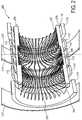
- Fig. 2shows a cross-sectional view of the windings 200 of an embodiment of a magnet assembly according to the invention.
- Inner coils of the magnetare labeled 110'.
- Outer coils of the magnetare labeled 110".
- the regions labeled 208show the location of where the rigid element would be.
- the inner 120 and outer 118 windingsare shown inside and outside of the region 208.
- the inner windings 120is the primary layer of the gradient coil windings and the outer windings 118 are the shield layer of the gradient coil windings.
- the axis labeled 210is a rotational axis of symmetry for the magnet assembly. This axis is located on a plane which divides the gradient coil into the first gradient coil section 112 and the second gradient coil section 114.
- the magnethas mirror- and rotational symmetry. The symmetry plane of the magnet coincides with the mid-plane of the gradient coil.
- the end flange conductor 202 of the gradient coilis located somewhere within the volume enclosed by the inner coil of the magnet 110' further from the mid-plane of the magnet. Without the end flange conductors the gradient coil would need to be made longer to achieve torque balancing. The further from the mid-plane of the magnet, the less homogeneous the magnetic field is. Inhomogeneities of the magnetic field can be used to design a gradient coil which is torque balanced.
- the flange conductor 204is also a flange conductor.
- the flange conductor 204is clearly not running radially outwards.
- the flange conductor 204starts and stops on a shield coil 118 winding.
- 206is a flange conductor near the mid-plane of the gradient coil.
- the flange conductor labeled 206is near the mid-plane of the gradient coil.
- the mid-plane of the gradient coilis where the gradient coil is split into the first and second gradient coil sections.
- the gradient coilalso features a recessed section of the primary gradient coil windings near the split between the first 112 and second 114 gradient coil sections.
- Figs. 3a, 3b and 3cshow examples of lap joints 300, 302, 304 which join the first gradient coil section 112 to the second gradient coil section 114.
- Fig. 3aa section of a cylindrical gradient coil is shown.
- the first gradient coil section 112is joined to the second gradient coil section 114 by an overlapping lap joint 300.
- a connecting element 116is shown as connecting the first gradient coil section 112 with the second gradient coil section 114.
- Fig. 3bis very similar to 3a except instead of using the overlapping joint a tongue-in-groove lap joint 302 is used. Then a connecting element 116 connects the first gradient coil section 112 to the second gradient coil section 114.
- a different style lap joint 304is shown.
- a connecting cylinder 306is used to join the first gradient coil section 112 with the second gradient coil section 114.
- a connecting element 116connects the first gradient coil section 112 to the connecting cylinder 306.
- the connecting cylinder 306is then connected via another section of 116 to the second gradient coil section 114.
- the connecting element 116is shown as two distinct pieces. However, in some embodiments a single piece of connecting element could be used.
- connecting element 116'which is between the first gradient coil section 112 and the second gradient coil section 114. This connecting element 116' is optional.
- the embodiment of Fig. 3ccould be combined with the embodiments shown in Figs. 3a or 3b .
- Fig. 4shows an example of a compression joint 400 which joins the first gradient coil section 112 to the second gradient coil section 114.
- the connecting element 116is compressed.
- Both the first gradient coil section 112 and the second gradient coil section 114have flanges 408. Going around the circumference of the gradient coil there may be a number of bolts 402 which are tightened using nuts 404.
- the combination of the bolt 402 and the nut 404is used to place the connecting element 116 under compression.
- the bolts 402 and the nuts 404are vibrationally isolated from the first and second gradient coil sections 112, 114 by vibration isolation elements 406.
- the vibration isolation elements 406may simply be large rubber washers which prevent the bolt 402 and the nut 404 from coming in direct contact with either the first gradient coil section 112 or the second gradient coil section 114.
- Fig. 5shows a functional block diagram of a magnetic resonance imaging system 500 according to an embodiment of the invention.
- the magnetic resonance imaging systemcomprises a magnetic resonance imaging magnet assembly according to an embodiment of the invention.
- the magnet assemblycomprises a magnet 102 and a gradient coil 103.
- the gradient coilcomprises a first gradient coil section 112 and a second gradient coil section 114 that is joined by a connecting element 116.
- the gradient coil 103is mounted in the magnet 102 using elastic mounts 126. In other embodiments the ends of the gradient coil 103 may be mounted to the magnet 102 using rigid mounts.
- elastic mounts 126have the advantage that they provide vibration isolation between the gradient coil 103 and the magnet 102.
- the magnet 102has an imaging zone 504. Within the imaging zone 504 the magnetic resonance imaging system 500 can acquire magnetic resonance data 536.
- a subject 502is shown partially within the imaging zone 504 and the subject 502 is supported by a subject support 506.
- the gradient coil 103is connected to a gradient coil power supply 508 which supplies current to the gradient coil 103.
- the first gradient coil section 112 and the second gradient coil section 114are connected separately to the gradient coil power supply 508.
- the first and second gradient coil sectionsmay also be supplied independently with a cooling fluid such as water. Alternatively the first and second gradient coil sections may be supplied by a single good cooling system.
- the magnetic resonance imaging system 500also comprises a radio frequency transceiver 510 which is connected to an antenna 512.
- the combination of the radio frequency transceiver 510 and the antenna 512allows the manipulation or the orientation of magnetic spins within the imaging zone 504.
- the radio frequency transceiver 510 and the antenna 512also allow the reception of magnetic resonance signals from within the imaging zone 504 also.
- the gradient coil power supply 508 and the radio frequency transceiver 510are connected to the hardware interface 516 of a computer system 514. Through the hardware interface 516 the computer system 514 is able to record the magnetic resonance symbols as magnetic resonance data 536.
- the computer systemfurther comprises a microprocessor 520 which is connected to the hardware interface 516, computer storage 518, computer memory 522 and a user interface 524.
- the storagemay be for example a hard drive.
- the memory 522may be random access memory.
- the user interface 524is an interface which a user uses to interact with the computer system 514. This interface may comprise such things as a display unit such as a computer display. It may also contain input devices such as a mouse, keyboard, or touch pad.
- the computer storage 518contains a program for the execution of software for controlling the magnetic resonance imaging system 500.
- the storage 518further contains a magnetic resonance image 534. This image 534 may be rendered on a display of the user interface 524.
- magnetic resonance data 536which was acquired by the magnetic resonance imaging system 500.
- the memory 522contains a copy of the program 532.
- the program 532 in memoryis labeled as 526.
- the program 526contains a module 528 for controlling the operation of the magnetic resonance imaging system.
- the program 526also contains a module 530 for performing image reconstruction. This is the reconstruction of magnetic resonance data 536 into a magnetic resonance image 534.
- a computer programmay be stored/distributed on a suitable medium, such as an optical storage medium or a solid-state medium supplied together with or as part of other hardware, but may also be distributed in other forms, such as via the Internet or other wired or wireless telecommunication systems. Any reference signs in the claims should not be construed as limiting the scope.
Landscapes
- Physics & Mathematics (AREA)
- Condensed Matter Physics & Semiconductors (AREA)
- General Physics & Mathematics (AREA)
- Health & Medical Sciences (AREA)
- Epidemiology (AREA)
- Magnetic Resonance Imaging Apparatus (AREA)
Description
- The invention relates to magnetic resonance imaging systems, in particular to the design of gradient coils for such systems.
- A static magnetic field is used by Magnetic Resonance Imaging (MRI) system to align the nuclear spins of atoms as part of the procedure for producing images within a subject. This static magnetic field is referred to as the B0 field or the main field.
- Magnetic field gradient coils are used to generate spatially and temporally variying magnetic fields which are used to spatially encode the nuclear spins being imaged. This spatial encoding is part of what allows the reconstruction of images from magnetic resonance imaging signals.
- However Magnetic Resoance Imaging is typically performed in a large magnetic field. As current flows through a magnetic field gradient coil the Lorentz force on the coil may be enormous. Gradient coils are typically mounted on or embedded within a rigid carrier to which these forces are transferred. During operation the large forces exerted by the Lorentz for can cause acoustic vibrations in the gradient coil and the rigid carrier. These acoustic vibrations may sound like a large knocking, thumping, or clicking sound during the use of the magnetic resonance imaging system.
- It is commonly known that increasing the strength of the B0 field used for performing a magnetic resoance imaging scan offers the opportunity of increasing the spatial resolution and contrast resolution of the diagnostics images. This increase in resolution and contrast benefits physicians using a magnetic resoance image to diagnose a patient. However as the strength of the B0 field increases, so do the Lorentz forces acting on the gradient coil during use. As the B0 field increases so does the noise generated by the gradient coils during operation.
- In the journal articleMichael Poole, Richard Bowtell, Concepts in Magnetic Resonance Part B, Vol. 31B(3), page 162-175, 2007 a method of designing gradient coils using the boundary element is disclosed. The minimization of a functional during the design process which imposes torque-balancing of the gradient coil is disclosed.
- In
United States Patent 5,764,059 , an acoustically screened magnetic coil which is adapted to be placed in a static magnetic field is disclosed. Essentially a combination of active and magnetic screening for gradient coils is disclosed. A closed loop of the gradient coil carrying current is arranged such that the two different parts of the loop are mechanically coupled, dimensioned and arranged such that the Lorentz forces experienced by the magnetic equipment are substantially reduced and preferably cancelled. - United States patent application
US 2004/0113619 A1 discloses a magnetic resonance device with a gradient coil system arranged in a cavity which has a lower mechanical stiffness than in edge regions. This eables the gradient coil to be securely and quietly attached to the magnetic resonance imaging system. PCT patent application publication WO 01/16616 A2 PCT patent application publication WO 96/31785 PCT patent application publication WO 97/35214 - Japanese patent abstract
JP 59 216045 A - United States patent
5,331,281 discloses a gradient magnetic field-generating coil assembly of MR imaging apparatus with a cylindrical core member for carrying coil windings that are divided into at least two cores at a central portion of a magnet bore. The natural vibration frequency of the core can be deviated from an exciting force frequency and sound prevailing in the outside of the core and sound in the inside can be brought into interference with each other to suppress vibration of the cores at the central portion of the magnet bore and reduce noise.WO 2008/122899 A1 discloses an axially split gradient coil assembly for MRI with primary and secondary conductors which are interconnected by flange conductors. - The invention provides for a gradient coil as defined by independent claim 14. Embodiments are given in the dependent claims.
- Magnetic resonance gradient coils exhibit mechanical resonance modes. This leads to increased acoustic noise at particular operating frequencies. Typically, gradient coils do not exhibit much mechanical damping, leading to enhanced vibration amplitudes at resonances. There is therefore a need to dampen such resonances. Attempts to dampen resonances have been largely unsuccessful, because the entire structure is optimized to withstand large Lorentz forces without mechanical failure. For example in United States Patent
5,764,059 column 10 lines 20 through 21 it is written: "Thus contrary to intuition, a light coupling structure of high strength is required." The design taught inUS 5,764,059 teaches a method of balancing forces between coils, but does not address the problems associated with acoustic resonances in the mechanical structure. - The use of the light coupling structure in
US 5,764,059 teaches away from the solution used by embodiments of the invention to dampen resonances: According the invention a mechanical damping structure is introduced into a region of the coil where no large forces are transmitted, and where significant relative motion occurs for damping material to be effective. It is preferable if damping layers are not bridged by conductors, since their mechanical stiffness would cancel the effect of the damping material. For a cylindrical gradient coil, the natural location for a damping layer is the z=0 mid-plane of the coil, but conventional gradient coils experience large bending forces acting on the mid-plane. The z direction is defined as being aligned with the axis of symmetry of a cylindrical magnet. - According to the invention, the acoustic noise emission of the gradient coils can be reduced by incorporating a mechanical damping material or elastic material, which reduces the mechanical quality factor of the structure. According to the invention, a cylindrical gradient coil is split mechanically in the z=0 mid-plane and the two halves are joined using an elastic material. A prerequisite for such a mechanical split is that each of the halves of the gradient coils does not experience net magnetic translational or rotational forces in the field of the main field magnet. This requirement can be met by suitable magnetic design of the coil systems.
- A gradient coil built according to the invention has the following features:
- 1. On splitting the coil about the z=0 plane, each half coil shall be force and torque-balanced when operated in the field of the magnet to which the coil is matched
- 2. The two halves of the coil are joined using mechanically elastic material such as to dampen the mechanical resonance modes of the coil. This elastic material may be incorporated in the form of a relatively thin layer of rubber.
- Balancing net translational forces on gradient coils can be achieved by incorporating appropriate design constraints in the gradient design software. In a similar way, the net rotational forces can be constrained, if the coil is modeled as two independent halves. Solutions exhibiting zero torque can be found if the length of the coil is typically equal to or greater than the length of the superconducting main field magnet. The range of solutions increases if conductors are allowed to be placed on the end and mid-plane flanges of the gradient coil. Zero torque solutions can even be found for coils having an asymmetric cross-section. The damping layer at the joint between the two coils can be a layer of rubber-like material. Pre-stressing or compressing may enhance the effect of a damping layer. Alternatively, the two halves of the coil can be joined by a thin-walled short cylinder, placed either on the outside or on the inside of the coil structure, using a lossy or material for the lap joint between the coil and the joining cylinder.
- A processor is an electronic component which is able to execute a program or machine executable instruction. References to the computing device comprising "a processor" should be interpreted as possibly containing more than one processor. The term computing device should also be interpreted to possibly refer to a collection or network of computing devices each comprising a processor. Many programs have their instructions performed by multiple processors that may be within the same computing device or which may even distributed across multiple computing device.
- A computer-readable storage medium as used herein is any storage medium which may store instructions which are executable by a processor of a computer or computing device. The computer-readable storage medium may be a computer-readable non-transitory storage medium. The computer-readable storage medium may also be a tangible computer readable medium. In some embodiments, a computer-readable storage medium may also be able to store data which is able to be accessed by the processor of the computing device. An example of a computer-readable storage medium include, but are not limited to: a floppy disk, a magnetic hard disk drive, a solid state hard disk, flash memory, a USB thumb drive, Random Access Memory (RAM) memory, Read Only Memory (ROM) memory, an optical disk, a magneto-optical disk, and the register file of the processor. Examples of optical disks include Compact Disks (CD) and Digital Versatile Disks (DVD), for example CD-ROM, CD-RW, CD-R, DVD-ROM, DVD-RW, or DVD-R disks. The term computer readable-storage medium also refers to various types of recording media capable of being accessed by the computer device via a network or communication link. For example a data may be retrieved over a modem, over the internet, or over a local area network.
- Computer memory is an example of a computer-readable storage medium. Computer memory is any memory which is directly accessible to a processor. Examples of computer memory include, but are not limited to: RAM memory, registers, and register files.
- Computer storage is an example of a computer-readable storage medium. Computer storage is any non-volatile computer-readable storage medium. Examples of computer storage include, but are not limited to: a hard disk drive, a USB thumb drive, a floppy drive, a smart card, a DVD, a CD-ROM, and a solid state hard drive. In some embodiments computer storage may also be computer memory or vice versa.
- In one aspect the invention provides for a magnetic resonance imaging magnet assembly as defined in claim 1. The magnet is adapted for generating a main magnetic field for aligning the magnetic spins of nuclei of a subject located within an imaging volume. The magnet may be a superconducting magnet, a permanent magnet, or a resistive electromagnet, or a combination of any of the three. The magnet assembly further comprises a gradient coil for generating a magnetic field for a spatial encoding of the magnetic resonance signal of the spins of nuclei within the imaging volume. The gradient coil is adapted to be mounted into the magnet. The gradient coil comprises a first gradient coil section. The gradient coil further comprises a second gradient coil section. The first gradient coil section comprises a first rigid element and the second gradient coil section comprises a second rigid element. For the cylindrically shaped gradient coil according to the invention, the first and second rigid elements are rigid tubes.
- The gradient coil further comprises a connecting element for joining the two half gradient coils. The connecting element comprises an elastic material. The elastic material is in contact with both the first and second elements. An example of an elastic material is rubber. The gradient coil may comprise three separate sets of coils. Each set of coils generates a gradient magnetic field in one of three spatial directions. They may be orthogonal and they may coincide with the geometric axes of x, y and z.
- Each of the first and second gradient coil sections may contain coil windings of each of the at least three gradient coil systems. This embodiment may be advantageous because dividing the coil into two sections changes the resonant properties of the gradient coil. This may lead to a reduction in acoustic noise during operation of the magnetic resonance imaging magnet assembly. For example during use a series of loud thumping or clicking sounds is heard when data is acquired with the magnetic resonance imaging system. Embodiments of the invention may reduce this acoustic noise and make it more comfortable for a patient to be examined in a magnetic resonance imaging system.
- According to the invention, both the first and second gradient coil sections comprise coil windings. The first and second gradient coil sections both comprise inner and outer windings. The inner windings provide the magnetic field for creating the gradient magnetic fields during operation. The outer windings may be shield windings which cancel the magnetic field from the gradient coil from inducing eddy currents in other parts of the magnetic resonance imaging magnet assembly. Such a gradient coil is known in the art as an active shielded gradient coil. The coil windings comprise flange conductors. The flange conductors are portions of the coil windings that go between the inner and outer windings. The flange conductors are designed such that the flange conductors are adapted to balance a torque exerted on the gradient coil by the main magnetic field during operation of the gradient coil. This is advantageous because each of the first and second gradient coil sections are each torque balanced. This will lead to less mechanical motion of the first and second gradient coil sections. This may lead to a reduction in noise during operation of the magnetic resonance imaging system.
- In an embodiment the coil windings of the first gradient coil section are rigidly attached to the first rigid element and the coil windings of the second gradient coil sections are rigidly attached to the second rigid element. This embodiment is advantageous because when current passes through a gradient coil and the gradient coil is in a large magnetic field there are Lorentz forces exerted on the coil winding. By having the coil windings rigidly attached to the rigid material the forces on the coil winding are transferred to the rigid material. In some embodiments the coil windings are fixed to the surface of the rigid elements and in other embodiments the coil winding are fully or partially embedded in the rigid elements.
- In another embodiment the first and second rigid elements are elastically mounted to the magnet. This embodiment is advantageous because the use of elastic material to join the first and second gradient coil sections to the magnet reduces the transfer of mechanical vibrations between the gradient coil sections and the magnet. This may lead to reduced acoustic noise during operation of the magnetic resonance imaging magnet.
- In another embodiment the connecting element comprises a viscous element that joins the first and second rigid elements. This embodiment is advantageous because the viscous element may dissipate acoustic vibrations between the first and second gradient coil sections. This may have the effect of reducing acoustic noise generated by the magnetic resonance imaging magnet assembly during use. The viscous element may be a material that is elastic and lossy. The viscous element may also be a mechanical element designed to dissipate energy. For instance small shock absorbers may be positioned between the first and second gradient coils to dissipate energy.
- In another embodiment the connecting element comprises a lap joint. A lap joint as used herein is an overlapping joint that connects two elements. For instance two elements may dovetail or have a notch which fits together. According to the invention, the first and second gradient coil sections are cylindrical. A larger cylinder overlaps both the first and second gradient coil sections and this overlapping cylinder forms the lap joint.
- In another embodiment the elastic material of the connecting element is compressed. For instance a flange system with bolts or threaded rods may be used to compress an elastic or for instance a rubber element between the first and second gradient coil sections. This embodiment is advantageous because it forms a joint that changes the acoustic resonance of the gradient coil and also may dissipate acoustic energy being transmitted between the first and second gradient coil sections.
- In another embodiment the first and second gradient coil sections are electrically isolated. This embodiment is advantageous because this prevents mechanical energy by being transmitted by the connections between the first and second gradient coil sections.
- In another embodiment the first and second gradient coil sections are connected electrically using bus bars. The bus bars are mounted elastically to the first and second rigid elements. This embodiment is advantageous because the first and second gradient coils can be connected electrically without acoustically coupling them. This may reduce the acoustic noise generated by the magnetic resonance imaging magnet assembly during operation.
- In another embodiment the first and second gradient coil sections have separate cooling water connections and electrical power connections. That is to say that the coils which make up each of the first and second gradient coil sections are powered separately. For instance the z coil in the first gradient coil section may be connected to a gradient coil power supply and the z coil of the second gradient coil section may also be connected separately to the same or a different power supply. By having separate cooling water connections and electrical power connections the acoustic coupling between the first and second gradient coil sections may be reduced. This may have the benefit of reducing the acoustic noise generated by the magnetic resonance imaging magnet assembly during operation.
- In another embodiment the first gradient coil section and the second gradient coil section are torque balanced for Lorentz forces in the magnetic field of the magnet. The first gradient coil section and the second gradient coil section are translational force balanced for Lorentz forces in the magnetic field of the magnet. This is advantageous because during use the magnets will not exert force on each other and this may have the effect of reducing noise generated by the magnetic resonance imaging magnet assembly.
- In another embodiment the elastic material couples vibrations between the first gradient coil section and the second gradient coil section. This has the effect of reducing the acoustic noise generated by the magnetic resonance imaging magnet assembly during operation. This is because the resonant frequency of the gradient coil is changed by doing this.
- In another embodiment the elastic material is a visco-elastic material. This embodiment is advantageous because the elastic material is lossy. That is to say that acoustic energy being transmitted between the two gradient coil sections is dissipated within the elastic material. This may have the effect of reducing the acoustic noise generated by the magnetic resonance imaging magnet assembly during operation.
- In another aspect the invention provides for a magnetic resonance imaging system as defined in claim 13. The magnetic resonance imaging system comprises a magnetic resonance imaging magnet assembly according to an embodiment of the invention. The magnetic resonance imaging system further comprises a radio frequency system for acquiring magnetic resonance data. Magnetic resonance data is defined herein as being the recorded measurements of radio frequency signals emitted by atomic spins by the antenna of a Magnetic resonance apparatus during a magnetic resonance imaging scan. A Magnetic Resonance Imaging (MRI) image is defined herein as being the reconstructed two or three dimensional visualization of anatomic data contained within the magnetic resonance data. This visualization can be performed using a computer.
- The radio frequency system is adapted to connect to a radio frequency antenna. The radio frequency system may be the combination of a transmitter and a receiver or it may be a transceiver. Accordingly the radio frequency antenna may be a single antenna which is used to send and receive radio signals or it may be a separate transmit and receive antenna. The magnetic resonance imaging system further comprises a magnetic field gradient coil power supply for supplying current to the magnetic field gradient coil. The magnetic resonance imaging system further comprises a computer system adapted for constructing images from the magnetic resonance data. The computer system is adapted for generating magnetic resonance images of the subject using the magnetic resonance data. The advantages of this embodiment have been previously discussed.
- In another aspect the invention provides for a gradient coil for generating a magnetic field for spatial encoding of the magnetic spins of nuclei within an imaging volume of a magnetic resonance imaging system as defined in claim 14. The gradient coil is adapted to be mounted into a magnet of the magnetic resonance imaging system. The gradient coil comprises a first gradient coil section. The first gradient coil section comprises a first rigid element. The gradient coil comprises a second gradient coil section. The second gradient coil section also comprises a second rigid element. The gradient coil further comprises a connecting element for joining the first and second gradient coil sections. The connecting element comprises an elastic material. The elastic material is in contact with the first and second rigid elements. The advantages of this gradient coil have been previously discussed.
- In the following preferred embodiments of the invention will be described, by way of example only, and with reference to the drawings in which:
Fig. 1 shows a cross-sectional view of a magnetic resonance imaging magnet assembly according to an embodiment of the invention;Fig. 2 shows a perspective, cross-sectional view of the windings of an embodiment of a magnet assembly according to the invention;Fig. 3A shows an example of lap joints according to an embodiment of the invention;Fig. 3B shows a further example of lap joints according to an embodiment of the invention;Fig. 3C shows a further example of lap joints according to an embodiment of the invention;Fig. 4 shows an example of a compression joint which compresses the connecting element according to an embodiment of the invention; andFig. 5 shows a functional block diagram of a magnetic resonance imaging system according to an embodiment of the invention.- Like numbered elements in these figures are either equivalent elements or perform the same function. Elements which have been discussed previously will not necessarily be discussed in later figures if the function is equivalent.
Fig. 1 shows a cross-sectional view of a magnetic resonanceimaging magnet assembly 100 according to an embodiment of the invention. Themagnet assembly 100 comprises amagnet 102 and agradient coil 103. Themagnet 102 shown in this Fig. is a magnet with a cylindrical symmetry. The axis ofsymmetry 104 of themagnet 102 is shown. Themagnet 102 comprises acryostat 106. Thecryostat 106 is surrounded by an insulation system which may comprise avacuum 108. The insulation system may also comprise a liquid nitrogen tank or vessel. Inside thecryostat 106 aresuperconducting coils 110.- The
gradient coil 103 comprises a firstgradient coil section 112 and a secondgradient coil section 114. The firstgradient coil section 112 and the secondgradient coil section 114 are joined by a connectingelement 116. The first gradient coil section comprises a firstrigid element 113. The second gradient coil section comprises a secondrigid element 115. The connecting element joins therigid elements gradient coil sections gradient coil sections outer windings 118 andinner windings 120. All of theouter windings 118 and theinner windings 120 are rigidly connected to therigid elements outer windings 118 of the first and secondgradient coil sections inner windings 120 of the first and secondgradient coil sections gradient coil 103 is shown as being mounted to themagnet 102 using the elastic mounts 126. - The elastic mounts 126 may be elastic or they may also be visco-elastic in which case acoustic energy is dissipated in the elastic mounts. Likewise the connecting element may be an elastic or viscous element. It may be an elastic element, or it may be a visco-elastic element. The connecting
element 116 serves during operation to change the resonant properties of thegradient coil 103. This may have the effect of reducing acoustic noise generated within themagnet assembly 100. Fig. 2 shows a cross-sectional view of thewindings 200 of an embodiment of a magnet assembly according to the invention. Inner coils of the magnet are labeled 110'. Outer coils of the magnet are labeled 110". The regions labeled 208 show the location of where the rigid element would be. The inner 120 and outer 118 windings are shown inside and outside of theregion 208. Theinner windings 120 is the primary layer of the gradient coil windings and theouter windings 118 are the shield layer of the gradient coil windings.- The axis labeled 210 is a rotational axis of symmetry for the magnet assembly. This axis is located on a plane which divides the gradient coil into the first
gradient coil section 112 and the secondgradient coil section 114. The magnet has mirror- and rotational symmetry. The symmetry plane of the magnet coincides with the mid-plane of the gradient coil. - 202 is a flange conductor. In this embodiment, the
end flange conductor 202 of the gradient coil is located somewhere within the volume enclosed by the inner coil of the magnet 110' further from the mid-plane of the magnet. Without the end flange conductors the gradient coil would need to be made longer to achieve torque balancing. The further from the mid-plane of the magnet, the less homogeneous the magnetic field is. Inhomogeneities of the magnetic field can be used to design a gradient coil which is torque balanced. - 204 is also a flange conductor. The
flange conductor 204 is clearly not running radially outwards. Theflange conductor 204 starts and stops on ashield coil 118 winding. - 206 is a flange conductor near the mid-plane of the gradient coil.
- The flange conductor labeled 206 is near the mid-plane of the gradient coil. The mid-plane of the gradient coil is where the gradient coil is split into the first and second gradient coil sections. The gradient coil also features a recessed section of the primary gradient coil windings near the split between the first 112 and second 114 gradient coil sections.
Figs. 3a, 3b and 3c show examples oflap joints gradient coil section 112 to the secondgradient coil section 114. InFig. 3a a section of a cylindrical gradient coil is shown. The firstgradient coil section 112 is joined to the secondgradient coil section 114 by an overlapping lap joint 300. A connectingelement 116 is shown as connecting the firstgradient coil section 112 with the secondgradient coil section 114.Fig. 3b is very similar to 3a except instead of using the overlapping joint a tongue-in-groove lap joint 302 is used. Then a connectingelement 116 connects the firstgradient coil section 112 to the secondgradient coil section 114.- In
Fig. 3c a different style lap joint 304 is shown. In the embodiment shown inFig. 3c a connectingcylinder 306 is used to join the firstgradient coil section 112 with the secondgradient coil section 114. A connectingelement 116 connects the firstgradient coil section 112 to the connectingcylinder 306. The connectingcylinder 306 is then connected via another section of 116 to the secondgradient coil section 114. In this embodiment the connectingelement 116 is shown as two distinct pieces. However, in some embodiments a single piece of connecting element could be used. Also shown is connecting element 116' which is between the firstgradient coil section 112 and the secondgradient coil section 114. This connecting element 116' is optional. In addition the embodiment ofFig. 3c could be combined with the embodiments shown inFigs. 3a or 3b . Fig. 4 shows an example of acompression joint 400 which joins the firstgradient coil section 112 to the secondgradient coil section 114. In this embodiment the connectingelement 116 is compressed. Both the firstgradient coil section 112 and the secondgradient coil section 114 haveflanges 408. Going around the circumference of the gradient coil there may be a number ofbolts 402 which are tightened using nuts 404. The combination of thebolt 402 and thenut 404 is used to place the connectingelement 116 under compression. Thebolts 402 and thenuts 404 are vibrationally isolated from the first and secondgradient coil sections vibration isolation elements 406. In this example thevibration isolation elements 406 may simply be large rubber washers which prevent thebolt 402 and thenut 404 from coming in direct contact with either the firstgradient coil section 112 or the secondgradient coil section 114.Fig. 5 shows a functional block diagram of a magnetic resonance imaging system 500 according to an embodiment of the invention. The magnetic resonance imaging system comprises a magnetic resonance imaging magnet assembly according to an embodiment of the invention. The magnet assembly comprises amagnet 102 and agradient coil 103. As was explained before the gradient coil comprises a firstgradient coil section 112 and a secondgradient coil section 114 that is joined by a connectingelement 116. Thegradient coil 103 is mounted in themagnet 102 usingelastic mounts 126. In other embodiments the ends of thegradient coil 103 may be mounted to themagnet 102 using rigid mounts. However,elastic mounts 126 have the advantage that they provide vibration isolation between thegradient coil 103 and themagnet 102.- The
magnet 102 has animaging zone 504. Within theimaging zone 504 the magnetic resonance imaging system 500 can acquiremagnetic resonance data 536. A subject 502 is shown partially within theimaging zone 504 and the subject 502 is supported by asubject support 506. Thegradient coil 103 is connected to a gradientcoil power supply 508 which supplies current to thegradient coil 103. In this example the firstgradient coil section 112 and the secondgradient coil section 114 are connected separately to the gradientcoil power supply 508. The first and second gradient coil sections may also be supplied independently with a cooling fluid such as water. Alternatively the first and second gradient coil sections may be supplied by a single good cooling system. - The magnetic resonance imaging system 500 also comprises a
radio frequency transceiver 510 which is connected to anantenna 512. The combination of theradio frequency transceiver 510 and theantenna 512 allows the manipulation or the orientation of magnetic spins within theimaging zone 504. Theradio frequency transceiver 510 and theantenna 512 also allow the reception of magnetic resonance signals from within theimaging zone 504 also. - The gradient
coil power supply 508 and theradio frequency transceiver 510 are connected to thehardware interface 516 of acomputer system 514. Through thehardware interface 516 thecomputer system 514 is able to record the magnetic resonance symbols asmagnetic resonance data 536. The computer system further comprises amicroprocessor 520 which is connected to thehardware interface 516,computer storage 518,computer memory 522 and auser interface 524. The storage may be for example a hard drive. Thememory 522 may be random access memory. Theuser interface 524 is an interface which a user uses to interact with thecomputer system 514. This interface may comprise such things as a display unit such as a computer display. It may also contain input devices such as a mouse, keyboard, or touch pad. - The
computer storage 518 contains a program for the execution of software for controlling the magnetic resonance imaging system 500. Thestorage 518 further contains amagnetic resonance image 534. Thisimage 534 may be rendered on a display of theuser interface 524. Also within thestorage 518 ismagnetic resonance data 536 which was acquired by the magnetic resonance imaging system 500. Thememory 522 contains a copy of theprogram 532. Theprogram 532 in memory is labeled as 526. Theprogram 526 contains amodule 528 for controlling the operation of the magnetic resonance imaging system. Theprogram 526 also contains amodule 530 for performing image reconstruction. This is the reconstruction ofmagnetic resonance data 536 into amagnetic resonance image 534. While the invention has been illustrated and described in detail in the drawings and foregoing description, such illustration and description are to be considered illustrative or exemplary and not restrictive; the invention is not limited to the disclosed embodiments. - Other variations to the disclosed embodiments can be understood and effected by those skilled in the art in practicing the claimed invention, from a study of the drawings, the disclosure, and the appended claims. In the claims, the word "comprising" does not exclude other elements or steps, and the indefinite article "a" or "an" does not exclude a plurality. A single processor or other unit may fulfill the functions of several items recited in the claims. The mere fact that certain measures are recited in mutually different dependent claims does not indicate that a combination of these measured cannot be used to advantage. A computer program may be stored/distributed on a suitable medium, such as an optical storage medium or a solid-state medium supplied together with or as part of other hardware, but may also be distributed in other forms, such as via the Internet or other wired or wireless telecommunication systems. Any reference signs in the claims should not be construed as limiting the scope.
- 100
- magnetic resonance imaging magnet assembly
- 102
- magnet
- 103
- gradient coil
- 104
- axis of symmetry
- 106
- cryostat
- 108
- vacuum
- 110
- superconducting coils
- 110'
- inner coils of magnet
- 110"
- outer coils of magnet
- 112
- first gradient coil section
- 113
- first rigid element
- 114
- second gradient coil section
- 115
- second rigid element
- 116
- connecting element
- 116'
- connecting element
- 118
- outer windings
- 120
- inner windings
- 122
- bus bar
- 124
- flange conductor
- 126
- elastic mount
- 200
- windings of magnet assembly
- 202
- flange conductor
- 204
- flange conductor
- 206
- flange conductor
- 208
- location of rigid element
- 210
- axis of rotational symmetry
- 300
- overlapping lap joint
- 302
- tongue in groove lap joint
- 304
- lap joint
- 306
- connecting cylinder
- 400
- compression joint
- 402
- bolt
- 404
- nut
- 406
- vibration isolation elements
- 500
- magnetic resonance imaging system
- 502
- subject
- 504
- imaging zone
- 506
- subject support
- 508
- gradient coil power supply
- 510
- radio frequency transceiver
- 512
- antenna
- 514
- computer system
- 516
- hardware interface
- 518
- storage
- 520
- processor
- 522
- memory
- 524
- user interface
- 526
- program
- 528
- control module
- 530
- image reconstruction module
- 532
- program
- 534
- magnetic resonance image
- 536
- magnetic resonance data
Claims (14)
- A magnetic resonance imaging magnet assembly (100) comprising:- a magnet (102) adapted for generating a main magnetic field for aligning the magnetic spins of nuclei of a subject (502) located within an imaging volume (504); and- a gradient coil (103) as defined in claim 14.
- The magnetic resonance imaging magnet assembly of Claim 1, wherein the coil windings of the first gradient coil section are rigidly attached to the first rigid element, and wherein the coil winding of the second gradient coil section are rigidly attached to the second rigid element.
- The magnetic resonance imaging magnet assembly of Claim 1 or 2, wherein both the first and second rigid elements are elastically mounted (126) to the magnet.
- The magnetic resonance imaging magnet assembly of any one of the preceding Claims, wherein the connecting element comprises a viscous element (116) that joins the first and second rigid elements.
- The magnetic resonance imaging magnet assembly of any one of Claims 1 through 4, wherein the connecting element comprises a lap joint (300, 302, 304).
- The magnetic resonance imaging magnet assembly of any one of Claims 1 through 4, wherein the elastic material of the connecting element is compressed (400).
- The magnetic resonance imaging magnet assembly of any one of the preceding Claims, wherein the first and second gradient coil sections are electrically isolated.
- The magnetic resonance imaging magnet assembly of any one of Claims 1 through 6, wherein the first and second gradient coil sections are connected electrically using bus bars (122), and wherein the bus bars are mounted elastically to the first and second rigid elements.
- The magnetic resonance imaging magnet assembly of Claim 7, wherein the first and second gradient coil sections have separate cooling water connections and electrical power connections.
- The magnetic resonance imaging magnet assembly of any one of the preceding Claims, wherein the first gradient coil section and the second gradient coil section are configured to be torque balanced for Lorentz forces in the magnetic field of the magnet, and wherein the first gradient coil section and the second gradient coil section are configured to be translational force balanced for Lorentz forces in the magnetic field of the magnet.
- The magnetic resonance imaging magnet assembly of any one of the preceding Claims, wherein the elastic material is configured to couple vibrations between the first gradient coil section and the second gradient coil section.
- The magnetic resonance imaging magnet assembly of Claim 1, wherein the elastic material is a visco-elastic material.
- A magnetic resonance imaging system comprising:- a magnetic resonance imaging magnet assembly (100) according to any one of the preceding claims;- a radio frequency system (510) for acquiring magnetic resonance data (536), wherein the radio frequency system is adapted to connect to a radio frequency antenna (512);- a magnetic field gradient coil power supply (508) for supplying current to the magnetic field gradient coil; and- a computer system (514) adapted for constructing images from magnetic resonance data and for controlling the operation of the magnetic resonance imaging system, wherein the computer system is adapted (530) for generating magnetic resonance images (534) of a subject (502) using the magnetic resonance data.
- A gradient coil (503) for generating a magnetic field for spatial encoding of the magnetic spins of nuclei within an imaging volume (504) of a magnetic resonance imaging system (500), wherein the gradient coil is adapted to be mounted into a magnet (102) of the magnetic resonance imaging system (500), wherein the gradient coil is cylindrical, wherein the gradient coil comprises:- a first gradient coil section (112), wherein the first gradient coil section comprises a first cylindrical rigid element (113);- a second gradient coil section (114), wherein the second gradient coil section comprises a second cylindrical rigid element (115); and- a connecting element (116, 300, 302, 304, 400) for joining the first and second gradient coil sections, wherein the gradient coil is split into the first gradient coil section and the second gradient coil section by a mid-plane of the gradient coil perpendicular to an axis of symmetry of the gradient coil, wherein the connecting element comprises an elastic material (116), wherein the elastic material is in contact with the first rigid element and the second rigid element, wherein both the first and second gradient coil sections comprise coil windings (118, 120), wherein both the first and second gradient coil sections comprise inner (120) and outer (118) coil windings located at the radially inner and outer sides of the respective cylindrical rigid element, respectively, wherein the coil windings comprise flange conductors (124, 202, 204, 206), wherein the flange conductors are portions of the coil windings that are adapted to conduct current between the inner and outer windings, and wherein the flange conductors are adapted to balance the torque exerted on the gradient coil by the main magnetic field of the magnetic resonance imaging system (500) during operation of the gradient coil.
Priority Applications (1)
| Application Number | Priority Date | Filing Date | Title |
|---|---|---|---|
| EP11724795.7AEP2572209B1 (en) | 2010-05-20 | 2011-05-13 | Magnetic resonance imaging gradient coil, magnet assembly, and system |
Applications Claiming Priority (3)
| Application Number | Priority Date | Filing Date | Title |
|---|---|---|---|
| EP10163363AEP2388610A1 (en) | 2010-05-20 | 2010-05-20 | Magnetic Resonance Imaging Gradient Coil, Magnet Assembly, and System |
| EP11724795.7AEP2572209B1 (en) | 2010-05-20 | 2011-05-13 | Magnetic resonance imaging gradient coil, magnet assembly, and system |
| PCT/IB2011/052102WO2011145029A1 (en) | 2010-05-20 | 2011-05-13 | Magnetic resonance imaging gradient coil, magnet assembly, and system |
Publications (2)
| Publication Number | Publication Date |
|---|---|
| EP2572209A1 EP2572209A1 (en) | 2013-03-27 |
| EP2572209B1true EP2572209B1 (en) | 2020-07-15 |
Family
ID=42352226
Family Applications (2)
| Application Number | Title | Priority Date | Filing Date |
|---|---|---|---|
| EP10163363AWithdrawnEP2388610A1 (en) | 2010-05-20 | 2010-05-20 | Magnetic Resonance Imaging Gradient Coil, Magnet Assembly, and System |
| EP11724795.7AActiveEP2572209B1 (en) | 2010-05-20 | 2011-05-13 | Magnetic resonance imaging gradient coil, magnet assembly, and system |
Family Applications Before (1)
| Application Number | Title | Priority Date | Filing Date |
|---|---|---|---|
| EP10163363AWithdrawnEP2388610A1 (en) | 2010-05-20 | 2010-05-20 | Magnetic Resonance Imaging Gradient Coil, Magnet Assembly, and System |
Country Status (6)
| Country | Link |
|---|---|
| US (1) | US9274192B2 (en) |
| EP (2) | EP2388610A1 (en) |
| CN (1) | CN102906588B (en) |
| BR (1) | BR112012029149A8 (en) |
| RU (1) | RU2562694C2 (en) |
| WO (1) | WO2011145029A1 (en) |
Families Citing this family (12)
| Publication number | Priority date | Publication date | Assignee | Title |
|---|---|---|---|---|
| US20120025829A1 (en)* | 2010-07-27 | 2012-02-02 | General Electric Company | Acoustically damped gradient coil |
| CN104898077B (en)* | 2014-03-07 | 2020-03-06 | 西门子(深圳)磁共振有限公司 | A holding device, method and system for a magnet coil of a magnetic resonance imaging system |
| CN104181477B (en)* | 2014-07-24 | 2015-12-02 | 上海联影医疗科技有限公司 | For support, the magnetic resonance system of magnetic resonance system |
| BR112017004353A2 (en) | 2014-09-05 | 2017-12-05 | Hyperfine Res Inc | ferromagnetic magnification for magnetic resonance imaging |
| CN107110929B (en)* | 2014-12-09 | 2019-08-16 | 圣纳普医疗(巴巴多斯)公司 | The system and method for electromagnetic coil structure |
| JP6490836B2 (en)* | 2015-05-12 | 2019-03-27 | コーニンクレッカ フィリップス エヌ ヴェKoninklijke Philips N.V. | Magnetic resonance inspection system using field probe |
| US10330816B2 (en)* | 2015-12-18 | 2019-06-25 | Schlumberger Technology Corporation | Imaging subterranean formations and features using azimuthal phase encoding |
| US10714960B2 (en)* | 2015-12-22 | 2020-07-14 | Intel Corporation | Uniform wireless charging device |
| EP3364206A1 (en)* | 2017-02-20 | 2018-08-22 | Koninklijke Philips N.V. | Gradient system with controlled cooling in the individual gradient channels |
| DE102018206643A1 (en)* | 2018-04-27 | 2019-10-31 | Siemens Healthcare Gmbh | Gradient coil unit for a magnetic resonance device |
| CN114664511B (en)* | 2022-04-11 | 2024-04-05 | 中国科学院电工研究所 | A superconducting magnet and gradient device for magnetic resonance imaging of micro-animals |
| CN116306017B (en)* | 2023-04-11 | 2024-06-11 | 浙江大学 | Low-noise magnetic resonance gradient coil design method based on elastomechanical modeling |
Family Cites Families (24)
| Publication number | Priority date | Publication date | Assignee | Title |
|---|---|---|---|---|
| JPS59216045A (en)* | 1983-05-23 | 1984-12-06 | Hitachi Ltd | Gradient field coil |
| NL8701947A (en)* | 1987-08-19 | 1989-03-16 | Philips Nv | MAGNETIC RESONANCE DEVICE WITH NOISELESS GRADIENT COIL. |
| JP3179805B2 (en)* | 1991-09-04 | 2001-06-25 | 株式会社日立メディコ | Gradient magnetic field generating coil for MR imaging system |
| RU2047871C1 (en)* | 1992-12-23 | 1995-11-10 | Российский научный центр "Курчатовский институт" | Magnetoresonant tomograph device |
| GB9311321D0 (en) | 1993-06-02 | 1993-07-21 | British Tech Group | Apparatus for and methods of acoustic and magnetic screening |
| US5497089A (en)* | 1994-03-15 | 1996-03-05 | Picker International, Inc. | Wide aperture gradient set |
| GB9506829D0 (en)* | 1995-04-01 | 1995-05-24 | Mansfield Peter | Active acoustic screening for quiet gradient coils in mri |
| US5729141A (en)* | 1996-03-19 | 1998-03-17 | Intermagnetics General Corporation | Split gradient coils for MRI system |
| US5952830A (en)* | 1997-12-22 | 1999-09-14 | Picker International, Inc. | Octapole magnetic resonance gradient coil system with elongate azimuthal gap |
| US6462547B1 (en)* | 1999-03-08 | 2002-10-08 | Siemens Aktiengesellschaft | Magnetic resonance tomography apparatus having a gradient coil system with a structural design wherein a scalar product of a natural oscillation mode and Lorentz forces is minimized toward zero |
| GB9920185D0 (en)* | 1999-08-27 | 1999-10-27 | Mansfield Peter | Active acoustic control for gradient coil structures in MRI |
| US6501978B2 (en)* | 1999-12-30 | 2002-12-31 | Transurgical, Inc. | Interleaved operation of MRI and electronic equipment |
| US6954068B1 (en)* | 2000-01-21 | 2005-10-11 | Kabushiki Kaisha Toshiba | Magnetic resonance imaging apparatus |
| US6437568B1 (en)* | 2000-10-02 | 2002-08-20 | General Electric Company | Low noise MRI scanner |
| US7504827B1 (en)* | 2001-11-14 | 2009-03-17 | Fonar Corporation | MRI test fixture |
| DE10246310A1 (en)* | 2002-10-04 | 2004-04-22 | Siemens Ag | Gradient coil system for MRI machine is made up of two or more units fixed into tubular casing using adhesive |
| DE10246309B3 (en)* | 2002-10-04 | 2004-08-12 | Siemens Ag | Magnetic resonance device with a cavity and with a gradient coil system arranged in the cavity |
| US6930482B2 (en)* | 2003-03-25 | 2005-08-16 | Siemens Aktiengesellschaft | Time-variable magnetic fields generator for a magnetic resonance apparatus |
| EP1771746A1 (en) | 2004-06-29 | 2007-04-11 | Koninklijke Philips Electronics N.V. | Magnetic resonance imaging device and method for operating a magnetic resonance imaging device |
| US20090209842A1 (en) | 2006-07-07 | 2009-08-20 | Koninklijke Philips Electronics N. V. | Mri gradient coil assembly with reduced acoustic noise |
| CN101688908B (en)* | 2007-04-04 | 2014-02-12 | 皇家飞利浦电子股份有限公司 | Split gradient coil and PET/MRI hybrid system using same |
| WO2009074918A1 (en) | 2007-12-11 | 2009-06-18 | Koninklijke Philips Electronics N.V. | Acoustic noise reduction in mri |
| US8419212B2 (en) | 2008-07-29 | 2013-04-16 | Tyco Electronics Corporation | Circuit board assembly with light emitting element |
| US8890529B2 (en)* | 2011-05-31 | 2014-11-18 | General Electric Company | System and apparatus for providing interconnections in a gradient coil assembly |
- 2010
- 2010-05-20EPEP10163363Apatent/EP2388610A1/ennot_activeWithdrawn
- 2011
- 2011-05-13WOPCT/IB2011/052102patent/WO2011145029A1/enactiveApplication Filing
- 2011-05-13EPEP11724795.7Apatent/EP2572209B1/enactiveActive
- 2011-05-13RURU2012155260/28Apatent/RU2562694C2/enactive
- 2011-05-13USUS13/696,127patent/US9274192B2/enactiveActive
- 2011-05-13CNCN201180024821.3Apatent/CN102906588B/enactiveActive
- 2011-05-13BRBR112012029149Apatent/BR112012029149A8/ennot_activeIP Right Cessation
Non-Patent Citations (1)
| Title |
|---|
| None* |
Also Published As
| Publication number | Publication date |
|---|---|
| BR112012029149A2 (en) | 2017-12-12 |
| RU2562694C2 (en) | 2015-09-10 |
| CN102906588B (en) | 2015-12-02 |
| RU2012155260A (en) | 2014-06-27 |
| WO2011145029A1 (en) | 2011-11-24 |
| EP2388610A1 (en) | 2011-11-23 |
| US20130106420A1 (en) | 2013-05-02 |
| BR112012029149A8 (en) | 2018-02-06 |
| US9274192B2 (en) | 2016-03-01 |
| CN102906588A (en) | 2013-01-30 |
| EP2572209A1 (en) | 2013-03-27 |
Similar Documents
| Publication | Publication Date | Title |
|---|---|---|
| EP2572209B1 (en) | Magnetic resonance imaging gradient coil, magnet assembly, and system | |
| US6437568B1 (en) | Low noise MRI scanner | |
| US7375526B2 (en) | Active-passive electromagnetic shielding to reduce MRI acoustic noise | |
| US7141974B2 (en) | Active-passive electromagnetic shielding to reduce MRI acoustic noise | |
| CA2871384C (en) | Acoustic noise reducing rf coil for magnetic resonance imaging | |
| JP4330447B2 (en) | Noise suppression in open MR system | |
| JP2007512074A (en) | Active shield gradient coil system with additional eddy current shielding system | |
| Motovilova et al. | Overview of methods for noise and heat reduction in MRI gradient coils | |
| JP5932815B2 (en) | Magnetic resonance imaging system | |
| JP6061518B2 (en) | System and apparatus for balancing radial forces in gradient coils | |
| US7307421B2 (en) | Magnetic resonance imaging device | |
| US6667619B2 (en) | Magnetic resonance apparatus with damping of inner mechanical vibrations | |
| JP2007111187A (en) | Rf coil and magnetic resonance imaging system | |
| JP6296631B2 (en) | Magnetic resonance imaging system | |
| JP2008119357A (en) | Rf coil for mri apparatus, method of usage of rf coil for mri apparatus, and mri apparatus | |
| JP4641727B2 (en) | Magnetic resonance imaging system | |
| JPWO2017033715A1 (en) | Magnetic resonance imaging system | |
| JP2011143033A (en) | Magnetic resonance imaging apparatus | |
| JP6660742B2 (en) | Magnetic resonance imaging equipment | |
| JP2009261747A (en) | Magnetic resonance imaging apparatus | |
| JP2012115456A (en) | Magnetic resonance imaging apparatus |
Legal Events
| Date | Code | Title | Description |
|---|---|---|---|
| PUAI | Public reference made under article 153(3) epc to a published international application that has entered the european phase | Free format text:ORIGINAL CODE: 0009012 | |
| 17P | Request for examination filed | Effective date:20121220 | |
| AK | Designated contracting states | Kind code of ref document:A1 Designated state(s):AL AT BE BG CH CY CZ DE DK EE ES FI FR GB GR HR HU IE IS IT LI LT LU LV MC MK MT NL NO PL PT RO RS SE SI SK SM TR | |
| DAX | Request for extension of the european patent (deleted) | ||
| RAP1 | Party data changed (applicant data changed or rights of an application transferred) | Owner name:KONINKLIJKE PHILIPS N.V. Owner name:PHILIPS INTELLECTUAL PROPERTY & STANDARDS GMBH | |
| GRAP | Despatch of communication of intention to grant a patent | Free format text:ORIGINAL CODE: EPIDOSNIGR1 | |
| STAA | Information on the status of an ep patent application or granted ep patent | Free format text:STATUS: GRANT OF PATENT IS INTENDED | |
| INTG | Intention to grant announced | Effective date:20200207 | |
| RAP1 | Party data changed (applicant data changed or rights of an application transferred) | Owner name:PHILIPS INTELLECTUAL PROPERTY & STANDARDS GMBH Owner name:KONINKLIJKE PHILIPS N.V. | |
| GRAS | Grant fee paid | Free format text:ORIGINAL CODE: EPIDOSNIGR3 | |
| GRAA | (expected) grant | Free format text:ORIGINAL CODE: 0009210 | |
| STAA | Information on the status of an ep patent application or granted ep patent | Free format text:STATUS: THE PATENT HAS BEEN GRANTED | |
| AK | Designated contracting states | Kind code of ref document:B1 Designated state(s):AL AT BE BG CH CY CZ DE DK EE ES FI FR GB GR HR HU IE IS IT LI LT LU LV MC MK MT NL NO PL PT RO RS SE SI SK SM TR | |
| REG | Reference to a national code | Ref country code:CH Ref legal event code:EP Ref country code:GB Ref legal event code:FG4D | |
| REG | Reference to a national code | Ref country code:DE Ref legal event code:R096 Ref document number:602011067754 Country of ref document:DE | |
| REG | Reference to a national code | Ref country code:IE Ref legal event code:FG4D | |
| REG | Reference to a national code | Ref country code:AT Ref legal event code:REF Ref document number:1291620 Country of ref document:AT Kind code of ref document:T Effective date:20200815 | |
| REG | Reference to a national code | Ref country code:DE Ref legal event code:R084 Ref document number:602011067754 Country of ref document:DE | |
| REG | Reference to a national code | Ref country code:LT Ref legal event code:MG4D | |
| REG | Reference to a national code | Ref country code:AT Ref legal event code:MK05 Ref document number:1291620 Country of ref document:AT Kind code of ref document:T Effective date:20200715 | |
| REG | Reference to a national code | Ref country code:GB Ref legal event code:746 Effective date:20201201 Ref country code:NL Ref legal event code:MP Effective date:20200715 | |
| REG | Reference to a national code | Ref country code:DE Ref legal event code:R081 Ref document number:602011067754 Country of ref document:DE Owner name:PHILIPS GMBH, DE Free format text:FORMER OWNER: PHILIPS INTELLECTUAL PROPERTY & STANDARDS GMBH, 20099 HAMBURG, DE | |
| PG25 | Lapsed in a contracting state [announced via postgrant information from national office to epo] | Ref country code:ES Free format text:LAPSE BECAUSE OF FAILURE TO SUBMIT A TRANSLATION OF THE DESCRIPTION OR TO PAY THE FEE WITHIN THE PRESCRIBED TIME-LIMIT Effective date:20200715 Ref country code:PT Free format text:LAPSE BECAUSE OF FAILURE TO SUBMIT A TRANSLATION OF THE DESCRIPTION OR TO PAY THE FEE WITHIN THE PRESCRIBED TIME-LIMIT Effective date:20201116 Ref country code:AT Free format text:LAPSE BECAUSE OF FAILURE TO SUBMIT A TRANSLATION OF THE DESCRIPTION OR TO PAY THE FEE WITHIN THE PRESCRIBED TIME-LIMIT Effective date:20200715 Ref country code:LT Free format text:LAPSE BECAUSE OF FAILURE TO SUBMIT A TRANSLATION OF THE DESCRIPTION OR TO PAY THE FEE WITHIN THE PRESCRIBED TIME-LIMIT Effective date:20200715 Ref country code:HR Free format text:LAPSE BECAUSE OF FAILURE TO SUBMIT A TRANSLATION OF THE DESCRIPTION OR TO PAY THE FEE WITHIN THE PRESCRIBED TIME-LIMIT Effective date:20200715 Ref country code:BG Free format text:LAPSE BECAUSE OF FAILURE TO SUBMIT A TRANSLATION OF THE DESCRIPTION OR TO PAY THE FEE WITHIN THE PRESCRIBED TIME-LIMIT Effective date:20201015 Ref country code:SE Free format text:LAPSE BECAUSE OF FAILURE TO SUBMIT A TRANSLATION OF THE DESCRIPTION OR TO PAY THE FEE WITHIN THE PRESCRIBED TIME-LIMIT Effective date:20200715 Ref country code:FI Free format text:LAPSE BECAUSE OF FAILURE TO SUBMIT A TRANSLATION OF THE DESCRIPTION OR TO PAY THE FEE WITHIN THE PRESCRIBED TIME-LIMIT Effective date:20200715 Ref country code:GR Free format text:LAPSE BECAUSE OF FAILURE TO SUBMIT A TRANSLATION OF THE DESCRIPTION OR TO PAY THE FEE WITHIN THE PRESCRIBED TIME-LIMIT Effective date:20201016 Ref country code:NO Free format text:LAPSE BECAUSE OF FAILURE TO SUBMIT A TRANSLATION OF THE DESCRIPTION OR TO PAY THE FEE WITHIN THE PRESCRIBED TIME-LIMIT Effective date:20201015 | |
| PG25 | Lapsed in a contracting state [announced via postgrant information from national office to epo] | Ref country code:LV Free format text:LAPSE BECAUSE OF FAILURE TO SUBMIT A TRANSLATION OF THE DESCRIPTION OR TO PAY THE FEE WITHIN THE PRESCRIBED TIME-LIMIT Effective date:20200715 Ref country code:RS Free format text:LAPSE BECAUSE OF FAILURE TO SUBMIT A TRANSLATION OF THE DESCRIPTION OR TO PAY THE FEE WITHIN THE PRESCRIBED TIME-LIMIT Effective date:20200715 Ref country code:PL Free format text:LAPSE BECAUSE OF FAILURE TO SUBMIT A TRANSLATION OF THE DESCRIPTION OR TO PAY THE FEE WITHIN THE PRESCRIBED TIME-LIMIT Effective date:20200715 Ref country code:IS Free format text:LAPSE BECAUSE OF FAILURE TO SUBMIT A TRANSLATION OF THE DESCRIPTION OR TO PAY THE FEE WITHIN THE PRESCRIBED TIME-LIMIT Effective date:20201115 | |
| PG25 | Lapsed in a contracting state [announced via postgrant information from national office to epo] | Ref country code:NL Free format text:LAPSE BECAUSE OF FAILURE TO SUBMIT A TRANSLATION OF THE DESCRIPTION OR TO PAY THE FEE WITHIN THE PRESCRIBED TIME-LIMIT Effective date:20200715 | |
| REG | Reference to a national code | Ref country code:DE Ref legal event code:R097 Ref document number:602011067754 Country of ref document:DE | |
| PG25 | Lapsed in a contracting state [announced via postgrant information from national office to epo] | Ref country code:SM Free format text:LAPSE BECAUSE OF FAILURE TO SUBMIT A TRANSLATION OF THE DESCRIPTION OR TO PAY THE FEE WITHIN THE PRESCRIBED TIME-LIMIT Effective date:20200715 Ref country code:RO Free format text:LAPSE BECAUSE OF FAILURE TO SUBMIT A TRANSLATION OF THE DESCRIPTION OR TO PAY THE FEE WITHIN THE PRESCRIBED TIME-LIMIT Effective date:20200715 Ref country code:IT Free format text:LAPSE BECAUSE OF FAILURE TO SUBMIT A TRANSLATION OF THE DESCRIPTION OR TO PAY THE FEE WITHIN THE PRESCRIBED TIME-LIMIT Effective date:20200715 Ref country code:EE Free format text:LAPSE BECAUSE OF FAILURE TO SUBMIT A TRANSLATION OF THE DESCRIPTION OR TO PAY THE FEE WITHIN THE PRESCRIBED TIME-LIMIT Effective date:20200715 Ref country code:DK Free format text:LAPSE BECAUSE OF FAILURE TO SUBMIT A TRANSLATION OF THE DESCRIPTION OR TO PAY THE FEE WITHIN THE PRESCRIBED TIME-LIMIT Effective date:20200715 Ref country code:CZ Free format text:LAPSE BECAUSE OF FAILURE TO SUBMIT A TRANSLATION OF THE DESCRIPTION OR TO PAY THE FEE WITHIN THE PRESCRIBED TIME-LIMIT Effective date:20200715 | |
| PLBE | No opposition filed within time limit | Free format text:ORIGINAL CODE: 0009261 | |
| STAA | Information on the status of an ep patent application or granted ep patent | Free format text:STATUS: NO OPPOSITION FILED WITHIN TIME LIMIT | |
| PG25 | Lapsed in a contracting state [announced via postgrant information from national office to epo] | Ref country code:AL Free format text:LAPSE BECAUSE OF FAILURE TO SUBMIT A TRANSLATION OF THE DESCRIPTION OR TO PAY THE FEE WITHIN THE PRESCRIBED TIME-LIMIT Effective date:20200715 | |
| 26N | No opposition filed | Effective date:20210416 | |
| PG25 | Lapsed in a contracting state [announced via postgrant information from national office to epo] | Ref country code:SK Free format text:LAPSE BECAUSE OF FAILURE TO SUBMIT A TRANSLATION OF THE DESCRIPTION OR TO PAY THE FEE WITHIN THE PRESCRIBED TIME-LIMIT Effective date:20200715 | |
| PG25 | Lapsed in a contracting state [announced via postgrant information from national office to epo] | Ref country code:SI Free format text:LAPSE BECAUSE OF FAILURE TO SUBMIT A TRANSLATION OF THE DESCRIPTION OR TO PAY THE FEE WITHIN THE PRESCRIBED TIME-LIMIT Effective date:20200715 | |
| REG | Reference to a national code | Ref country code:CH Ref legal event code:PL | |
| PG25 | Lapsed in a contracting state [announced via postgrant information from national office to epo] | Ref country code:CH Free format text:LAPSE BECAUSE OF NON-PAYMENT OF DUE FEES Effective date:20210531 Ref country code:MC Free format text:LAPSE BECAUSE OF FAILURE TO SUBMIT A TRANSLATION OF THE DESCRIPTION OR TO PAY THE FEE WITHIN THE PRESCRIBED TIME-LIMIT Effective date:20200715 Ref country code:LU Free format text:LAPSE BECAUSE OF NON-PAYMENT OF DUE FEES Effective date:20210513 Ref country code:LI Free format text:LAPSE BECAUSE OF NON-PAYMENT OF DUE FEES Effective date:20210531 | |
| REG | Reference to a national code | Ref country code:BE Ref legal event code:MM Effective date:20210531 | |
| PG25 | Lapsed in a contracting state [announced via postgrant information from national office to epo] | Ref country code:IE Free format text:LAPSE BECAUSE OF NON-PAYMENT OF DUE FEES Effective date:20210513 | |
| PG25 | Lapsed in a contracting state [announced via postgrant information from national office to epo] | Ref country code:FR Free format text:LAPSE BECAUSE OF NON-PAYMENT OF DUE FEES Effective date:20210531 | |
| PG25 | Lapsed in a contracting state [announced via postgrant information from national office to epo] | Ref country code:BE Free format text:LAPSE BECAUSE OF NON-PAYMENT OF DUE FEES Effective date:20210531 | |
| PG25 | Lapsed in a contracting state [announced via postgrant information from national office to epo] | Ref country code:HU Free format text:LAPSE BECAUSE OF FAILURE TO SUBMIT A TRANSLATION OF THE DESCRIPTION OR TO PAY THE FEE WITHIN THE PRESCRIBED TIME-LIMIT; INVALID AB INITIO Effective date:20110513 Ref country code:CY Free format text:LAPSE BECAUSE OF FAILURE TO SUBMIT A TRANSLATION OF THE DESCRIPTION OR TO PAY THE FEE WITHIN THE PRESCRIBED TIME-LIMIT Effective date:20200715 | |
| PG25 | Lapsed in a contracting state [announced via postgrant information from national office to epo] | Ref country code:MK Free format text:LAPSE BECAUSE OF FAILURE TO SUBMIT A TRANSLATION OF THE DESCRIPTION OR TO PAY THE FEE WITHIN THE PRESCRIBED TIME-LIMIT Effective date:20200715 | |
| PG25 | Lapsed in a contracting state [announced via postgrant information from national office to epo] | Ref country code:TR Free format text:LAPSE BECAUSE OF FAILURE TO SUBMIT A TRANSLATION OF THE DESCRIPTION OR TO PAY THE FEE WITHIN THE PRESCRIBED TIME-LIMIT Effective date:20200715 | |
| PG25 | Lapsed in a contracting state [announced via postgrant information from national office to epo] | Ref country code:MT Free format text:LAPSE BECAUSE OF FAILURE TO SUBMIT A TRANSLATION OF THE DESCRIPTION OR TO PAY THE FEE WITHIN THE PRESCRIBED TIME-LIMIT Effective date:20200715 | |
| PGFP | Annual fee paid to national office [announced via postgrant information from national office to epo] | Ref country code:DE Payment date:20250528 Year of fee payment:15 | |
| PGFP | Annual fee paid to national office [announced via postgrant information from national office to epo] | Ref country code:GB Payment date:20250520 Year of fee payment:15 |