EP2571405B1 - Beverage production system using capsules - Google Patents
Beverage production system using capsulesDownload PDFInfo
- Publication number
- EP2571405B1 EP2571405B1EP11723893.1AEP11723893AEP2571405B1EP 2571405 B1EP2571405 B1EP 2571405B1EP 11723893 AEP11723893 AEP 11723893AEP 2571405 B1EP2571405 B1EP 2571405B1
- Authority
- EP
- European Patent Office
- Prior art keywords
- capsule
- engagement member
- beverage production
- beverage
- module
- Prior art date
- Legal status (The legal status is an assumption and is not a legal conclusion. Google has not performed a legal analysis and makes no representation as to the accuracy of the status listed.)
- Active
Links
Images


Classifications
- A—HUMAN NECESSITIES
- A47—FURNITURE; DOMESTIC ARTICLES OR APPLIANCES; COFFEE MILLS; SPICE MILLS; SUCTION CLEANERS IN GENERAL
- A47J—KITCHEN EQUIPMENT; COFFEE MILLS; SPICE MILLS; APPARATUS FOR MAKING BEVERAGES
- A47J31/00—Apparatus for making beverages
- A47J31/24—Coffee-making apparatus in which hot water is passed through the filter under pressure, i.e. in which the coffee grounds are extracted under pressure
- A47J31/34—Coffee-making apparatus in which hot water is passed through the filter under pressure, i.e. in which the coffee grounds are extracted under pressure with hot water under liquid pressure
- A47J31/36—Coffee-making apparatus in which hot water is passed through the filter under pressure, i.e. in which the coffee grounds are extracted under pressure with hot water under liquid pressure with mechanical pressure-producing means
- A47J31/3604—Coffee-making apparatus in which hot water is passed through the filter under pressure, i.e. in which the coffee grounds are extracted under pressure with hot water under liquid pressure with mechanical pressure-producing means with a mechanism arranged to move the brewing chamber between loading, infusing and ejecting stations
- A47J31/3623—Cartridges being employed
- A47J31/3638—Means to eject the cartridge after brewing
- A—HUMAN NECESSITIES
- A47—FURNITURE; DOMESTIC ARTICLES OR APPLIANCES; COFFEE MILLS; SPICE MILLS; SUCTION CLEANERS IN GENERAL
- A47J—KITCHEN EQUIPMENT; COFFEE MILLS; SPICE MILLS; APPARATUS FOR MAKING BEVERAGES
- A47J31/00—Apparatus for making beverages
- A47J31/24—Coffee-making apparatus in which hot water is passed through the filter under pressure, i.e. in which the coffee grounds are extracted under pressure
- A47J31/34—Coffee-making apparatus in which hot water is passed through the filter under pressure, i.e. in which the coffee grounds are extracted under pressure with hot water under liquid pressure
- A47J31/36—Coffee-making apparatus in which hot water is passed through the filter under pressure, i.e. in which the coffee grounds are extracted under pressure with hot water under liquid pressure with mechanical pressure-producing means
- A—HUMAN NECESSITIES
- A47—FURNITURE; DOMESTIC ARTICLES OR APPLIANCES; COFFEE MILLS; SPICE MILLS; SUCTION CLEANERS IN GENERAL
- A47J—KITCHEN EQUIPMENT; COFFEE MILLS; SPICE MILLS; APPARATUS FOR MAKING BEVERAGES
- A47J31/00—Apparatus for making beverages
- A—HUMAN NECESSITIES
- A47—FURNITURE; DOMESTIC ARTICLES OR APPLIANCES; COFFEE MILLS; SPICE MILLS; SUCTION CLEANERS IN GENERAL
- A47J—KITCHEN EQUIPMENT; COFFEE MILLS; SPICE MILLS; APPARATUS FOR MAKING BEVERAGES
- A47J31/00—Apparatus for making beverages
- A47J31/24—Coffee-making apparatus in which hot water is passed through the filter under pressure, i.e. in which the coffee grounds are extracted under pressure
- A47J31/34—Coffee-making apparatus in which hot water is passed through the filter under pressure, i.e. in which the coffee grounds are extracted under pressure with hot water under liquid pressure
- A47J31/36—Coffee-making apparatus in which hot water is passed through the filter under pressure, i.e. in which the coffee grounds are extracted under pressure with hot water under liquid pressure with mechanical pressure-producing means
- A47J31/3604—Coffee-making apparatus in which hot water is passed through the filter under pressure, i.e. in which the coffee grounds are extracted under pressure with hot water under liquid pressure with mechanical pressure-producing means with a mechanism arranged to move the brewing chamber between loading, infusing and ejecting stations
- A47J31/3623—Cartridges being employed
- A47J31/3628—Perforating means therefor
- A—HUMAN NECESSITIES
- A47—FURNITURE; DOMESTIC ARTICLES OR APPLIANCES; COFFEE MILLS; SPICE MILLS; SUCTION CLEANERS IN GENERAL
- A47J—KITCHEN EQUIPMENT; COFFEE MILLS; SPICE MILLS; APPARATUS FOR MAKING BEVERAGES
- A47J31/00—Apparatus for making beverages
- A47J31/24—Coffee-making apparatus in which hot water is passed through the filter under pressure, i.e. in which the coffee grounds are extracted under pressure
- A47J31/34—Coffee-making apparatus in which hot water is passed through the filter under pressure, i.e. in which the coffee grounds are extracted under pressure with hot water under liquid pressure
- A47J31/36—Coffee-making apparatus in which hot water is passed through the filter under pressure, i.e. in which the coffee grounds are extracted under pressure with hot water under liquid pressure with mechanical pressure-producing means
- A47J31/3604—Coffee-making apparatus in which hot water is passed through the filter under pressure, i.e. in which the coffee grounds are extracted under pressure with hot water under liquid pressure with mechanical pressure-producing means with a mechanism arranged to move the brewing chamber between loading, infusing and ejecting stations
- A47J31/3623—Cartridges being employed
- A47J31/3633—Means to perform transfer from a loading position to an infusing position
- A—HUMAN NECESSITIES
- A47—FURNITURE; DOMESTIC ARTICLES OR APPLIANCES; COFFEE MILLS; SPICE MILLS; SUCTION CLEANERS IN GENERAL
- A47J—KITCHEN EQUIPMENT; COFFEE MILLS; SPICE MILLS; APPARATUS FOR MAKING BEVERAGES
- A47J31/00—Apparatus for making beverages
- A47J31/40—Beverage-making apparatus with dispensing means for adding a measured quantity of ingredients, e.g. coffee, water, sugar, cocoa, milk, tea
- A47J31/407—Beverage-making apparatus with dispensing means for adding a measured quantity of ingredients, e.g. coffee, water, sugar, cocoa, milk, tea with ingredient-containing cartridges; Cartridge-perforating means
- A—HUMAN NECESSITIES
- A47—FURNITURE; DOMESTIC ARTICLES OR APPLIANCES; COFFEE MILLS; SPICE MILLS; SUCTION CLEANERS IN GENERAL
- A47J—KITCHEN EQUIPMENT; COFFEE MILLS; SPICE MILLS; APPARATUS FOR MAKING BEVERAGES
- A47J31/00—Apparatus for making beverages
- A47J31/44—Parts or details or accessories of beverage-making apparatus
Definitions
- the present inventionrelates to the field of producing beverages or other liquid comestibles on the basis of ingredients which are contained in a capsule.
- the capsuleis inserted into the beverage production module of a beverage production machine.
- the moduleis designed to inject a liquid such as for example hot water into the capsule in order to have the liquid interacts with the ingredients contained in the capsule.
- a liquidsuch as for example hot water
- beverage production techniquesask for a pressurized injection like coffee beverage, others such as e.g. brewing tea can be made at ambient pressure.
- the inventioncan find application in both scenarios.
- the result of the interactioni.e. the produced beverage or liquid comestible, is then drained from the capsule and fed to a receptacle such as e.g. a cup placed below an outlet for the beverage.
- the inventionrelates particularly to beverage production machines comprising a module with a first capsule engagement member, which can be displaced relative to a second co-operating capsule engagement member between an opened capsule insertion position and a closed capsule-enclosure position.
- the modulecomprises means for actively retracting the capsule from the beverage production position to a capsule discharge position in which the capsule is discharged from the module.
- Such a machinepresents the advantage of having a capsule discharge position which is offset relative to the beverage production position. This advantage is of interest when the machine and the capsule are conceived for delivering the beverage directly out of the capsule in a cup without the beverage contacting the machine since it enables the discharge of the capsule in a position which is offset relative to the vertical of the beverage flow path.
- Such a beverage production machineis described in EP-A1-2 033 551 .
- the capsuleis introduced in the beverage production module, retains by pre-fixation arms in a pre-engagement position and then engaged by a first engagement member that is conformal to the capsule shape further to the movement of the first engagement member to the capsule.
- the capsuleis clamped between the first and the second engagement members and the diluent, generally water, can be introduced to interact with the ingredients in the capsule.
- the resulting beverageflows out of the capsule either through en outlet provided in the capsule or/and produced by the machine during the capsule engagement and falls by gravity in a cup.
- the first engagement membermoves back to the capsule discharge position dragging the capsule towards a position offset relative to the vertical of the beverage flow path.
- the movement of the first engagement memberis a combination of a linear movement and an end swivelling movement so that the capsule can fall by gravity from the first engagement member.
- Such a machinecomprises in its first capsule engagement member a hollow needle for opening the capsule and injecting water in the capsule.
- this needleis retractable and the retraction can help in ejecting the capsule from the first engagement member at the capsule discharge position.
- the needleis not retractable and continuously protrudes in the first capsule engagement member and in the capsule. This needle may retain the capsule in the first engagement member in spite of the swivelling movement and may prevent the discharge of the capsule from the beverage production module, which would block the machine.
- the inventionnow targets at a reliable discharge of the capsule from such a beverage production machine, particularly the machine described in EP-A1-2 053 551 .
- a beverage production system according to the preamble of independent claim 1is disclosed in WO-A-2005/058111 .
- This objectis achieved by means of specific features of the machine and the capsules.
- This systemcomprising these both objects guarantees a systematic efficient discharge of the capsule from the capsule engagement member.
- the inventionconcerns a beverage production system comprising a capsule and a module for producing a beverage from the capsule,
- the module for producing a beverage of the systemcan present the features of the module described in EP-A1-2033551 . It comprises two co-operating capsule engagement members, the first member being displaceable between a closed position in which the capsule is engaged between the two members and called the beverage production position and an open position in which no capsule is engaged by the members and called the capsule discharge position. According to the invention the capsule discharge position is offset relative to the vertical of the beverage flow path that is to the beverage production position.
- the modulecomprises means for displacing the first capsule engagement member between the two positions.
- the moduleis designed for injecting water into the capsule and draining the beverage from the capsule while the capsule is in the beverage production position.
- the capsule of the system of the present inventioncomprises an enclosure in which beverage ingredients are contained. These ingredients can be for example selected in the following list : tea leaves, herbal or fruit tea leaves, roast and ground coffee, soluble beverage ingredient, ...
- the enclosureis usually a cup-shaped housing which can encompass different cross sections such as triangular, circular, ellipsoid, egg-shaped, square, rectangular or polygonal section.
- the enclosureis usually closed by a cover, preferably a plane cover.
- the capsule of the present inventionalso presents a rim at the edge of the enclosure. The cover can be fixed on this rim.
- the capsuleis preferably made of a material sufficiently rigid (either due to its nature or to its thickness) so that it is not deformed by the friction means of the first capsule engagement member when it is engaged in said member. Otherwise the friction force could not be sufficiently strong to retain the capsule during the movement of the first capsule engagement member.
- the displaceable first capsule engagement membercomprises an element having the shape of a hollow bell member and the capsule presents an enclosure outer shape that is conformal to at least a portion of said hollow bell member.
- conformalit is meant that the capsule outer shape is defined in order to match at least a portion of the hollow bell shape outer shape.
- at least a part of the outer contour of the capsulecan be housed in the hollow bell member.
- the capsulepresents a rim size such that at least a part of the rim of the capsule extends beyond the first capsule engagement member once it is engaged in the first capsule engagement member.
- the displaceable first capsule engagement membercomprises retaining means able to create a friction with discrete parts of the outer shape of the enclosure of the capsule.
- These retaining meanscan be friction means that exerts a friction on the capsule enclosure outer wall when it is engaged in the first capsule engagement member.
- These retaining meansare preferably positioned inside the hollow bell member of the first engagement member
- the retaining means that engage discrete parts of the periphery of the outer shape of the enclosure of the capsuleare discrete bumps placed on the internal surface of the hollow bell member of the first capsule engagement member.
- the bumpsare made of a flexible and resilient material.
- the materialcan be elastomeric, for example a silicone rubber or an EPDM (ethylene propylene diene monomer) rubber.
- the bumpsare preferably placed by pairs at the internal surface of the hollow bell member and the two bumps of a pair are symmetrically opposed in view of the symmetrical plane or axis of the capsule when it is engaged in the first capsule engagement member. Then each pair of bumps forms a sort of pair of pliers that maintains and retains the capsule in the first capsule engagement member when this member moves back to the capsule discharge position.
- the first engagement membercan comprise four bumps, the first pair being vertically opposed along the plane of symmetry and the second pair being horizontally opposed in view of the plan of symmetry.
- the modulecomprises also means for engaging the rim of the capsule that extends beyond the first capsule engagement member when the first capsule engagement member is displaced from the beverage production position to its capsule discharge position.
- This meanscan simply be a tab extending from the housing of the beverage machine supporting the module.
- the means for actively retracting the first capsule engagement member from the beverage production position to the capsule discharge positionare designed to implement the combination of a linear movement and a swivelling end movement.
- the first capsule engagement membercomprises opening means for piercing the capsule and injecting water in the capsule.
- the opening meanscan be a hollow needle linked to water supply.
- the module of the system of the present inventioncomprises pre-fixation means which are provided at a lateral side of the capsule and designed to engage with the rim of the capsule for fixation of the capsule close to the second engagement member before the beverage production.
- the modulecan comprise means for opening the cover. These means are generally placed adjacent to the second capsule engagement member or can even be part of this second capsule engagement member.
- beverage production module 2 of a beverage production machineis shown.
- the beverage production module 2is supplied with a liquid at a liquid inlet 14 which can be in fluid connection with means for heating and/or pressurizing the supplied liquid.
- a liquid inlet 14which can be in fluid connection with means for heating and/or pressurizing the supplied liquid.
- means for guiding a produced beverage or liquid comestible to a designated outlet of the beverage production machinecan be provided.
- the beverage production module 2 as shown in the figuresis preferably housed in a casing of the beverage production machine such that it assumes an essentially horizontal position.
- Figure 1 ashows a state of the beverage production module 2 in which a capsule 1 being at least partially filled with ingredients 5 can be inserted from the top through an opening (slot) 8 of a casing 19 of the beverage production module 2.
- Figure 1 ashows the state in which the capsule 1 has been already manually inserted by a user from the top through the opening 8 into the interior of the casing 19 of the beverage module 2.
- the capsule 1is held by pre-fixation means which will be explained later on in detail referring to Fig. 6 and 7 .
- the capsule 1is preferably held in an essentially vertical orientation, i.e.
- the symmetrical axis of the capsuleis essentially horizontal.
- Other pre-positioning arrangements of the capsule 1can be thought of in which the capsule 1 is held in an orientation which forms a small (acute) angle vis-à-vis the vertical axis.
- a second engagement member 4which can comprise means for opening (perforating, etc.) the face of the capsule adjacent to the second engagement member 4.
- This second engagement member 4can also comprise means for or guiding a produced beverage or liquid comestible from the capsule 1 to a cup.
- the first engagement member 3is in an opened state, i.e. as controlled by a manual actuator mechanism in the capsule insertion state as shown in Fig.
- the first capsule engaging member 3is distanced from the second engagement member 4, wherein this distance is substantially larger than the corresponding dimensions of the capsule 1.
- the first engagement member 3is not only distanced from, but also slightly rotated vis-à-vis the main plane formed by the second engagement member 4.
- the first engagement member 3is provided with capsule opening means, which can be perforation means such as a hollow needle 6.
- the perforation means 6are in a position in which they are retracted such that they do not protrude into a half dome formed by a hollow bell member 13 of the first engagement member 3.
- the perforation means 6are not retractable but fixed in the first engagement member 3.
- the hollow bell member 13has an essentially matching shape to the contour of the capsule 1.
- the rear end of the first engagement member 3is provided with a liquid supply 14 which is in fluid connection with the hollow needle (perforation member) 6.
- the first engagement member 3is connected to an actuator mechanism 7.
- the actuator mechanism 7comprises a manually operable lever handle 9 and the first engagement member 3 is connected to the lever handle 9 by means of a knee-joint mechanism 11 which can preferably comprise several axis 10 and intermediate levers 20.
- the actuator mechanism 7is designed to control the displacement of the first engagement member 3 and optionally the displacement of the perforation member 6. Note that alternatively or additionally an electric actuator can be used.
- the lever handle 9 of the actuator mechanism 7By operating the lever handle 9 of the actuator mechanism 7, the first engagement member 3 can be transferred into an intermediate stage as shown in Fig. 1b .
- the beverage production module 2can be transferred from the intermediate stage as shown in Fig. 1b to a final closure state as shown in Fig. 1c .
- the perforation member 6is characterized in that the hollow bell member 13 still fully engages the capsule 1, however, also mechanically controlled by manipulating the actuator mechanism 7, the perforation member 6 has been actively pushed from its retracted position ( Fig. 1a, 1b ) to a protruding position as shown in Fig. 1c .
- the perforation member 6will perforate the associated face of the capsule 1 and will at least partially protrude into the interior of the capsule 1, except if this perforation member is not retractable, in which case the capsule has been already pierced by the needle.
- the liquid supplied to the liquid supply 14 of the first engagement member 3can be injected into the interior of capsule 1 through the perforation member 6.
- the injected liquidcan be made to interact with the ingredients of the capsule 1 in order to produce a beverage or another liquid comestible.
- the first capsule engagement member 3has been moved along a composite trajectory vis-à-vis the second engagement member 4.
- the composite trajectorypreferably comprises a rotational movement at the beginning in order to align the front contour 21 of the first engagement member 3 with the vertical plane of the second engagement member 4.
- the perforation position of the capsule 1also corresponds to the beverage production position in which the liquid is injected into the capsule 1.
- Figures 2a to 2eessentially show the same transition from the capsule insertion state of the beverage production module 2 to the final closure state of Fig. 2c , which is only also the beverage production state of the beverage production module 2.
- the actuator means 7can again be manually and/or electrically operated in order to transfer the beverage production module 2 back to the opened capsule insertion state ( Fig. 2e ).
- the first engagement member 3is controlled to carry out a swivelling movement.
- the perforation member 6is finally made to be retracted from the hollow bell member 13.
- the capsule 1which has been hitherto retained by the frictional engagement with the perforation member 6, will drop from the first capsule engagement member 3 and will be discharged from the beverage module 2 through an opening 24 at the lower side of the beverage production module 2.
- the swivelling movement at the end of the trajectory of the first capsule engagement member 3facilitates the discharge of the capsule 1 in the retracted position e.g. towards a waste container placed inside the beverage production machine and below the beverage production module 2.
- the swivelling movementmay not be sufficient to discharge the capsule 1, particularly if the customer has not discharged the capsule immediately after the beverage production step : some residues of the beverage may escape from the capsule through the hole pierced by the opening member 6, dry and stick the capsule external surface to the hollow bell member 13.
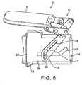
- the actuator mechanism 7comprises a lever handle 9 acting on a knee-joint mechanism 11, wherein the extremity of the actuator mechanism 7 being at the opposite end of the lever handle 9 comprises a first control curve 17.
- This first control curve 17cooperates with a guiding pin 16 which is fixed to the lateral side of the first capsule engagement member 3. Therefore, the cooperation of the first guiding curve 17 with the guiding pin 16 is designed to selectively displace the first engagement member 3, to which is also fixed the perforation member 6 linked to the diluent supply 14.
- the first guiding curve 17is essentially composed of a first linear section 29 and a second linear section 30, being shorter than the first linear section 29 and forming an obtuse angle vis-à-vis the first linear section 29.
- the guiding pin 16When starting from the capsule insertion position (level 9 in vertical position) the guiding pin 16 is made to cooperate with the first linear section 29 which is designed to linearly and integrally displace the first engagement member 3.
- the guiding pin 16is made to cooperate with the second linear section 30 of the guiding curve 17.
- the guiding pin 16is also made to cooperate with a second guiding curve 18 provided in the lateral walls of the casing 19 of the beverage production module 2.
- the second guiding curve 18is composed of at least two different segments, such as for example an essentially horizontal linear segment 21 and an inclined linear segment 20 being raised to the rear end of the module.
- the first engagement member 3carries out an essentially linear relative movement vis-à-vis the second engagement member 4 when the first and the second engagement member are close together, while the upwards inclined second linear segment 20 of the control curve 18 results in the swivelling movement of the first engagement member 3 such that the half dome defined by the bell member 13 is rotated slightly downwards.
- Figures 3illustrates a first capsule engagement member 13 and Figure 4 illustrates a capsule 1 able to be used with said first capsule engagement member according to the system of the present invention.
- the first engagement member 3presents a hollow bell member 13.
- the capsulepresents an enclosure outer shape 1 a that is conformal to at least a portion of the hollow bell member 13.
- opening means of the capsuleusually a hollow needle 6, is fixed for piercing the capsule and injecting water.
- the first engagement member 3also comprises retaining means able to exert frictions with discrete parts of the outer shape 1a of the enclosure of the capsule. These means can be discrete bumps 3c placed at different places of the first engagement member internal shape periphery.
- the seal and the bumpsare preferably made of a flexible and resilient material. Then the seal can then be flattened against the rim of the capsule during the beverage production step.
- the bumps 3ccan deform themselves when the first engagement member engages the capsule. The fact that the bumps 3c are placed face to face on different sides of the internal face of the bell shape member 13 improves the way to retain the capsule and avoids that the latter falls from the first engagement member on the way to the capsule discharge position.
- the seal and the bumpscan be made of an elastomeric material, for example a silicone or an EPDM (ethylene propylene diene monomer) rubber.
- the bumps of the first pairare placed at the top and at the bottom of the internal face of the hollow bell member 13, whereas the bumps of the other pair are symmetrically opposed in view of the symmetrical vertical plane of the capsule or of the hollow bell member 13. Due to the fact that the capsule enclosure outer shape 1 b is conformal to the hollow bell member 13 internal surface, the bumps 3c retain the capsule inside the first capsule engagement member when said member moves to the capsule discharge position.
- the capsule 1also comprises a size such that at least a part of its rim 1 b extends beyond at least a part of the first capsule engagement member 3 once the capsule is engaged in the first capsule engagement member.
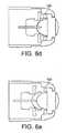
- Figure 5aillustrates a back view of the first capsule engagement member 13 with the capsule 1 engaged in the hollow bell member 13. Some parts of the rim 1b of the capsule extend beyond the limits of the first capsule engagement member. It is preferable that at least a vertical part of the rim 1b extends beyond the limits of the first capsule engagement member. The term vertical is to be interpreted according to the position of the capsule inside the module.
- the first capsule engagement member 3also comprises means for coupling 3e said member to means of displacement and means 3d for cooperating with the pre-fixation means provided at a lateral side of the capsule cage and means 3d designed to engage with the rim 1 b of the capsule for fixation of the capsule close to the second engagement member.
- the term cagedesignates the hollow bell shaped member.
- Figure 5billustrates a front view of the first capsule engagement member 13 and the capsule 1 engaged in the hollow bell member 13.
- the bumps 3care illustrated in dotted points.
- Figures 6a-6eillustrates the steps of introducing the capsule in the first and second engagement members 3, 4.
- the capsule 1is pre-positioned by pre-fixation means , such as for example flexible capsule pre-fixation arms 12.
- pre-fixation meanssuch as for example flexible capsule pre-fixation arms 12.
- the arms 12When seen from above the arms 12 are provided at the lateral sides of the capsule.
- the flexible arms 12respectively present a vertical groove 31 made to engage with the rim 1b of the capsule 1. Therefore, when the capsule 1 is inserted manually by a user from the top of the beverage production module, it will be initially pre-positioned and held in place by the flexible arms 12.
- the prefixed arms 12are moved away making the capsule 1 leave the pre-fixation position in the vertical grooves 31 and pushing the capsule 1 against the second engagement member as shown in figure 6c
- meanscan be provided to actively disengage the rim 1b of the capsule with the pre-fixation means (flexible arms) 12.
- the first engagement member 3can be operatively connected to disengagement means 32 which cooperate with a slanted surface 33 of the flexible arms 12 in order to push the flexible arms 12 to the outside and thus to disengage the vertical grooves 31 of the flexible arms 12 from the rim 1 b of the capsule.
- the capsule 1is made to be disengaged from the flexible arms 12 serving as pre-fixation means ( figure 6c ).
- the rim of the capsule 1is pushed behind the grooves 31 of the flexible arms 12.
- the disengagement member 32 of the first engagement member 3will again cooperate with specifically designed surfaces of flexible arms 12 in order to spread these arms 12 and thus have the capsule 1 pass these arms 12 without being engaged by the arms 12.
- Figures 6d and 6erepresent the intermediate position between the beverage production position and the capsule discharge position wherein tabs 12b retain the part of the capsule rim 1 b extending beyond the capsule engagement member 3. These tabs can be fixed to the flexible arms 12 or other part of the module 3 or the beverage machine housing.
- Figure 6eillustrates the position where the tabs 12b have retained the capsule rim 1b whereas the capsule engagement member 3 continues its return to the final position such as illustrated in Figure 6a .
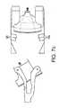
- Figures 7a-7cillustrates the steps of disengaging the capsule from the first and second engagement members 3, 4, and discharging the capsule 1 according to another embodiment thant the one illustrated in Figures 6a-6e .
- Each figures 7a-7cpresents a top and side view of the first engagement member 3, the capsule 1 and the pre-fixation arms 12.
- Figures 7arelate to these elements placed in the beverage production position.
- the pre-fixation arms 12were pushed away from the capsule rim 1 b due to the engagement of the cooperating means 3d of the first capsule engagement member 3 with a slanted portion 12a of the pre-fixation means.
- the size of the rim 1b of the capsuleis designed so as not be too large so as to enable the back movement of the capsule without engaging the pre-fixation arms.
- Figures 7brepresent the intermediate position between the beverage production position and the capsule discharge position wherein tabs 12b fixed to a part of each of the flexible arms of the pre-fixation means 12 retain the part of the capsule rim extending beyond the capsule engagement member.
- These tabscan be fixed to other part of the module or the beverage machine housing.
- the tabsare positioned to retain the capsule rim 1b where the opened face of the hollow bell member 13 is oriented downward.
- Figures 7crepresent the final position of the capsule discharge position where the capsule 1 has been discharged from the first capsule engagement member by the two pairs of tabs 12b fixed each of the flexible arms of the pre-fixation means 12 and where the first capsule engagement member 3 finished its movement by a swivelling movement.
- the capsulemust present a rim sufficiently large to be retained by the pre-fixation means and by the means for engaging the rim when the capsule is moved to the capsule discharge position, but not too large to be able to not be engaged by the pre-fixation means during the back movement to the capsule discharge position.
- the capsulemust also present an enclosure external shape such that at least discrete parts of said enclosure are submitted to friction by the retaining means of the capsule cage when the capsule is engaged in the latter.
Landscapes
- Engineering & Computer Science (AREA)
- Food Science & Technology (AREA)
- Mechanical Engineering (AREA)
- Apparatus For Making Beverages (AREA)
Description
- The present invention relates to the field of producing beverages or other liquid comestibles on the basis of ingredients which are contained in a capsule.
- The capsule is inserted into the beverage production module of a beverage production machine. The module is designed to inject a liquid such as for example hot water into the capsule in order to have the liquid interacts with the ingredients contained in the capsule. Note that some beverage production techniques ask for a pressurized injection like coffee beverage, others such as e.g. brewing tea can be made at ambient pressure. The invention can find application in both scenarios. The result of the interaction, i.e. the produced beverage or liquid comestible, is then drained from the capsule and fed to a receptacle such as e.g. a cup placed below an outlet for the beverage.
- The invention relates particularly to beverage production machines comprising a module with a first capsule engagement member, which can be displaced relative to a second co-operating capsule engagement member between an opened capsule insertion position and a closed capsule-enclosure position. The module comprises means for actively retracting the capsule from the beverage production position to a capsule discharge position in which the capsule is discharged from the module. Such a machine presents the advantage of having a capsule discharge position which is offset relative to the beverage production position. This advantage is of interest when the machine and the capsule are conceived for delivering the beverage directly out of the capsule in a cup without the beverage contacting the machine since it enables the discharge of the capsule in a position which is offset relative to the vertical of the beverage flow path. Such a beverage production machine is described in
EP-A1-2 033 551 . - In such a machine, the capsule is introduced in the beverage production module, retains by pre-fixation arms in a pre-engagement position and then engaged by a first engagement member that is conformal to the capsule shape further to the movement of the first engagement member to the capsule. At the end of this movement, the capsule is clamped between the first and the second engagement members and the diluent, generally water, can be introduced to interact with the ingredients in the capsule. The resulting beverage flows out of the capsule either through en outlet provided in the capsule or/and produced by the machine during the capsule engagement and falls by gravity in a cup. Once the beverage has been delivered, the first engagement member moves back to the capsule discharge position dragging the capsule towards a position offset relative to the vertical of the beverage flow path. The movement of the first engagement member is a combination of a linear movement and an end swivelling movement so that the capsule can fall by gravity from the first engagement member.
- Yet it has been noticed that the end swivelling movement is not systematically sufficient to make the capsule drop from the first engagement member to a capsule recovery container, particularly if the consumer has not discharged the capsule immediately after having prepared a beverage. In this situation it has been noticed that the capsule can stick to the first engagement member and that the capsule does not disengage which blocks the machine.
- Besides such a machine comprises in its first capsule engagement member a hollow needle for opening the capsule and injecting water in the capsule. According to an embodiment this needle is retractable and the retraction can help in ejecting the capsule from the first engagement member at the capsule discharge position. But according to another embodiment, the needle is not retractable and continuously protrudes in the first capsule engagement member and in the capsule. This needle may retain the capsule in the first engagement member in spite of the swivelling movement and may prevent the discharge of the capsule from the beverage production module, which would block the machine.
- The invention now targets at a reliable discharge of the capsule from such a beverage production machine, particularly the machine described in
EP-A1-2 053 551 . A beverage production system according to the preamble of independent claim 1 is disclosed inWO-A-2005/058111 . - This object is achieved by means of specific features of the machine and the capsules. This system comprising these both objects guarantees a systematic efficient discharge of the capsule from the capsule engagement member.
- The invention concerns a beverage production system comprising a capsule and a module for producing a beverage from the capsule,
- the capsule comprising an enclosure and a rim, and
- the module comprising :
- a first capsule engagement member, which can be displaced relative to a second, co-operating capsule engagement member between a beverage production position and a capsule discharge position,
- means for actively retracting the first capsule engagement member from the beverage production position to the capsule discharge position in which the capsule is discharged from the first capsule engagement member and which is offset relative to the vertical of the beverage flow path,
- The module for producing a beverage of the system can present the features of the module described in
EP-A1-2033551 . It comprises two co-operating capsule engagement members, the first member being displaceable between a closed position in which the capsule is engaged between the two members and called the beverage production position and an open position in which no capsule is engaged by the members and called the capsule discharge position. According to the invention the capsule discharge position is offset relative to the vertical of the beverage flow path that is to the beverage production position. - The module comprises means for displacing the first capsule engagement member between the two positions.
- Generally the module is designed for injecting water into the capsule and draining the beverage from the capsule while the capsule is in the beverage production position.
- The capsule of the system of the present invention comprises an enclosure in which beverage ingredients are contained. These ingredients can be for example selected in the following list : tea leaves, herbal or fruit tea leaves, roast and ground coffee, soluble beverage ingredient, ... The enclosure is usually a cup-shaped housing which can encompass different cross sections such as triangular, circular, ellipsoid, egg-shaped, square, rectangular or polygonal section. The enclosure is usually closed by a cover, preferably a plane cover. The capsule of the present invention also presents a rim at the edge of the enclosure. The cover can be fixed on this rim. The capsule is preferably made of a material sufficiently rigid (either due to its nature or to its thickness) so that it is not deformed by the friction means of the first capsule engagement member when it is engaged in said member. Otherwise the friction force could not be sufficiently strong to retain the capsule during the movement of the first capsule engagement member.
- According to the invention the displaceable first capsule engagement member comprises an element having the shape of a hollow bell member and the capsule presents an enclosure outer shape that is conformal to at least a portion of said hollow bell member. By "conformal", it is meant that the capsule outer shape is defined in order to match at least a portion of the hollow bell shape outer shape. Thus at least a part of the outer contour of the capsule can be housed in the hollow bell member.
- Besides the capsule presents a rim size such that at least a part of the rim of the capsule extends beyond the first capsule engagement member once it is engaged in the first capsule engagement member.
- According to the invention the displaceable first capsule engagement member comprises retaining means able to create a friction with discrete parts of the outer shape of the enclosure of the capsule. These retaining means can be friction means that exerts a friction on the capsule enclosure outer wall when it is engaged in the first capsule engagement member.These retaining means are preferably positioned inside the hollow bell member of the first engagement member
- According to a preferred embodiment the retaining means that engage discrete parts of the periphery of the outer shape of the enclosure of the capsule are discrete bumps placed on the internal surface of the hollow bell member of the first capsule engagement member. Preferably the bumps are made of a flexible and resilient material. The material can be elastomeric, for example a silicone rubber or an EPDM (ethylene propylene diene monomer) rubber.
- If the capsule section presents a symmetrical shape, the bumps are preferably placed by pairs at the internal surface of the hollow bell member and the two bumps of a pair are symmetrically opposed in view of the symmetrical plane or axis of the capsule when it is engaged in the first capsule engagement member. Then each pair of bumps forms a sort of pair of pliers that maintains and retains the capsule in the first capsule engagement member when this member moves back to the capsule discharge position.
- Even more preferably, if the capsule presents a vertical plan of symmetry in its extracting position then the first engagement member can comprise four bumps, the first pair being vertically opposed along the plane of symmetry and the second pair being horizontally opposed in view of the plan of symmetry.
- According to the invention the module comprises also means for engaging the rim of the capsule that extends beyond the first capsule engagement member when the first capsule engagement member is displaced from the beverage production position to its capsule discharge position. This means can simply be a tab extending from the housing of the beverage machine supporting the module.
- Preferably in the module of the system of the present invention the means for actively retracting the first capsule engagement member from the beverage production position to the capsule discharge position are designed to implement the combination of a linear movement and a swivelling end movement.
- Usually the first capsule engagement member comprises opening means for piercing the capsule and injecting water in the capsule. The opening means can be a hollow needle linked to water supply.
- Preferably the module of the system of the present invention comprises pre-fixation means which are provided at a lateral side of the capsule and designed to engage with the rim of the capsule for fixation of the capsule close to the second engagement member before the beverage production.
- The module can comprise means for opening the cover. These means are generally placed adjacent to the second capsule engagement member or can even be part of this second capsule engagement member.
- The characteristics and advantages of the invention will be better understood in relation to
Fig. 1a-1c show a sequence for illustrating the transfer from a capsule insertion state, (Fig. 1a ) to a beverage production position (Fig. 1c ) with a beverage machine in which the system of the present invention can be implemented,Fig. 2a-2e show the complete cycle for transferring a beverage production module that can be implemented according to the present invention from a capsule insertion state (Fig. 2a ) to a capsule production position (Fig. 2c ) and to the capsule discharge position (Fig. 2e ).Figure 3 illustrates a first capsule engagement member used in the system of the present invention.Figure 4 illustrates a capsule used in the system of the present invention with the first capsule engagement member ofFigure 3 .Figure 5a is a back view of the first capsule engagement member ofFigure 3 with the capsule ofFigure 4 engaged inside andFig.5b is the corresponding front view.Figures 6a-6e illustrate the relative positions of first capsule engagement member, the capsule and the pre-fixation means during the movement of the first capsule engagement member during a cycle of beverage production according to a first embodiment.Figures 7a-7c illustrate the relative positions of first capsule engagement member, the capsule and the pre-fixation means during the movement of the first capsule engagement member from the beverage production position (fig. 7a ) to the capsule discharge position (fig. 7c ) according to a second embodiment.Figure 8 shows an isolated view of the first engagement member and the means for displacing said member.- Throughout the figures only the beverage production module 2 of a beverage production machine is shown. Usually the beverage production module 2 is supplied with a liquid at a
liquid inlet 14 which can be in fluid connection with means for heating and/or pressurizing the supplied liquid. At the outlet side, means for guiding a produced beverage or liquid comestible to a designated outlet of the beverage production machine can be provided. The beverage production module 2 as shown in the figures is preferably housed in a casing of the beverage production machine such that it assumes an essentially horizontal position. Figure 1 a shows a state of the beverage production module 2 in which a capsule 1 being at least partially filled with ingredients 5 can be inserted from the top through an opening (slot) 8 of acasing 19 of the beverage production module 2.Figure 1 a shows the state in which the capsule 1 has been already manually inserted by a user from the top through theopening 8 into the interior of thecasing 19 of the beverage module 2. Preferably in the state as shown inFig. 1a the capsule 1 is held by pre-fixation means which will be explained later on in detail referring toFig. 6 and7 . As can be seen inFig. 1a , in this pre-fixation position the capsule 1 is preferably held in an essentially vertical orientation, i.e. the symmetrical axis of the capsule is essentially horizontal. Other pre-positioning arrangements of the capsule 1 can be thought of in which the capsule 1 is held in an orientation which forms a small (acute) angle vis-à-vis the vertical axis. In the state as shown inFig. 1a the capsule is pre-fixed close to a second engagement member 4 which can comprise means for opening (perforating, etc.) the face of the capsule adjacent to the second engagement member 4. This second engagement member 4 can also comprise means for or guiding a produced beverage or liquid comestible from the capsule 1 to a cup. Thefirst engagement member 3 is in an opened state, i.e. as controlled by a manual actuator mechanism in the capsule insertion state as shown inFig. 1a , the firstcapsule engaging member 3 is distanced from the second engagement member 4, wherein this distance is substantially larger than the corresponding dimensions of the capsule 1. According to a preferred aspect which will be explained in detail later on, optionally thefirst engagement member 3 is not only distanced from, but also slightly rotated vis-à-vis the main plane formed by the second engagement member 4.- In the embodiment of
Fig. 1 thefirst engagement member 3 is provided with capsule opening means, which can be perforation means such as ahollow needle 6. InFig. 1 a the perforation means 6 are in a position in which they are retracted such that they do not protrude into a half dome formed by ahollow bell member 13 of thefirst engagement member 3. According to the preferred embodiment (not illustrated inFig.1 ) the perforation means 6 are not retractable but fixed in thefirst engagement member 3. Thehollow bell member 13 has an essentially matching shape to the contour of the capsule 1. The rear end of thefirst engagement member 3 is provided with aliquid supply 14 which is in fluid connection with the hollow needle (perforation member) 6. - The
first engagement member 3 is connected to an actuator mechanism 7. According to a first embodiment the actuator mechanism 7 comprises a manuallyoperable lever handle 9 and thefirst engagement member 3 is connected to thelever handle 9 by means of a knee-joint mechanism 11 which can preferably compriseseveral axis 10 andintermediate levers 20. The actuator mechanism 7 is designed to control the displacement of thefirst engagement member 3 and optionally the displacement of theperforation member 6. Note that alternatively or additionally an electric actuator can be used. By operating the lever handle 9 of the actuator mechanism 7, thefirst engagement member 3 can be transferred into an intermediate stage as shown inFig. 1b . The intermediate stage as shown inFig. 1b is characterized in that thehollow bell member 13 has essentially fully engaged the outer contour of the capsule 1, while the hollow needle (perforation member) 6 is still in its retracted position vis-à-vis thebell member 13 and correspondingly theperforation member 6 is not yet interfering with the capsule 1. If the hollow needle is not retractable, the capsule has been already pierced by the needle in this position. Now, when turning the lever handle 9 further in the anti-clockwise direction, the beverage production module 2 can be transferred from the intermediate stage as shown inFig. 1b to a final closure state as shown inFig. 1c . The final closure state as shown inFig. 1c is characterized in that thehollow bell member 13 still fully engages the capsule 1, however, also mechanically controlled by manipulating the actuator mechanism 7, theperforation member 6 has been actively pushed from its retracted position (Fig. 1a, 1b ) to a protruding position as shown inFig. 1c . By being actively moved from the retracted position to the protruding position as shown inFig. 1c , theperforation member 6 will perforate the associated face of the capsule 1 and will at least partially protrude into the interior of the capsule 1, except if this perforation member is not retractable, in which case the capsule has been already pierced by the needle. - In this state the liquid supplied to the
liquid supply 14 of thefirst engagement member 3 can be injected into the interior of capsule 1 through theperforation member 6. Thus, in the state as shown inFig. 1c the injected liquid can be made to interact with the ingredients of the capsule 1 in order to produce a beverage or another liquid comestible. - During the transition from the capsule insertion state of
Fig. 1a to the final closure state as shown inFig. 1c , the firstcapsule engagement member 3 has been moved along a composite trajectory vis-à-vis the second engagement member 4. The composite trajectory preferably comprises a rotational movement at the beginning in order to align thefront contour 21 of thefirst engagement member 3 with the vertical plane of the second engagement member 4. Both in the intermediate stages shown inFig. 1b and the final closure state as shown inFig. 1c the capsule 1 is held safely in a defined position by having a flange-like rim portion 1 b of the capsule being clamped between the rim of thefront contour 21 of thefirst engagement member 3 and in associated clampingsurface 23 of the second engagement member 4. - Preferably the perforation position of the capsule 1 also corresponds to the beverage production position in which the liquid is injected into the capsule 1.
Figures 2a to 2e essentially show the same transition from the capsule insertion state of the beverage production module 2 to the final closure state ofFig. 2c , which is only also the beverage production state of the beverage production module 2. After the end of the beverage production, the actuator means 7 can again be manually and/or electrically operated in order to transfer the beverage production module 2 back to the opened capsule insertion state (Fig. 2e ).- As it is shown in
Fig. 2d and Fig. 2e , when manually moving the lever handle 9 of the actuator mechanism 7 in the clockwise direction of the embodiment ofFig. 2 , in a first step thefirst engagement member 3 is linearly retracted and distanced from the second engagement member 4. The holding-back function of theperforation member 6 of thefirst engagement member 3 leads to a separation of the capsule 1 from the second capsule engagement member 4. - Starting from the intermediate state as shown in
Fig. 2d thefirst engagement member 3 is controlled to carry out a swivelling movement. During the final transition to the capsule insertion state as shown inFig. 2e theperforation member 6 is finally made to be retracted from thehollow bell member 13. The capsule 1 which has been hitherto retained by the frictional engagement with theperforation member 6, will drop from the firstcapsule engagement member 3 and will be discharged from the beverage module 2 through an opening 24 at the lower side of the beverage production module 2. Thus, the swivelling movement at the end of the trajectory of the firstcapsule engagement member 3 facilitates the discharge of the capsule 1 in the retracted position e.g. towards a waste container placed inside the beverage production machine and below the beverage production module 2. - Yet where the opening
member 6 is not retractable from thehollow bell member 13, the swivelling movement may not be sufficient to discharge the capsule 1, particularly if the customer has not discharged the capsule immediately after the beverage production step : some residues of the beverage may escape from the capsule through the hole pierced by the openingmember 6, dry and stick the capsule external surface to thehollow bell member 13. - As shown in
Fig.7 , the actuator mechanism 7 comprises alever handle 9 acting on a knee-joint mechanism 11, wherein the extremity of the actuator mechanism 7 being at the opposite end of thelever handle 9 comprises afirst control curve 17. Thisfirst control curve 17 cooperates with a guidingpin 16 which is fixed to the lateral side of the firstcapsule engagement member 3. Therefore, the cooperation of thefirst guiding curve 17 with the guidingpin 16 is designed to selectively displace thefirst engagement member 3, to which is also fixed theperforation member 6 linked to thediluent supply 14. Thefirst guiding curve 17 is essentially composed of a first linear section 29 and a secondlinear section 30, being shorter than the first linear section 29 and forming an obtuse angle vis-à-vis the first linear section 29. When starting from the capsule insertion position (level 9 in vertical position) the guidingpin 16 is made to cooperate with the first linear section 29 which is designed to linearly and integrally displace thefirst engagement member 3. On the other hand, in the final phase, i.e. when thefirst engagement member 3 approaches the beverage production state (level 9 in horizontal position), the guidingpin 16 is made to cooperate with the secondlinear section 30 of the guidingcurve 17. The guidingpin 16 is also made to cooperate with asecond guiding curve 18 provided in the lateral walls of thecasing 19 of the beverage production module 2. Thesecond guiding curve 18 is composed of at least two different segments, such as for example an essentially horizontallinear segment 21 and an inclinedlinear segment 20 being raised to the rear end of the module. Due to the cooperation of the guidingpin 16 with this particular design of thesecond guiding curve 18, thefirst engagement member 3 carries out an essentially linear relative movement vis-à-vis the second engagement member 4 when the first and the second engagement member are close together, while the upwards inclined secondlinear segment 20 of thecontrol curve 18 results in the swivelling movement of thefirst engagement member 3 such that the half dome defined by thebell member 13 is rotated slightly downwards. Figures 3 illustrates a firstcapsule engagement member 13 andFigure 4 illustrates a capsule 1 able to be used with said first capsule engagement member according to the system of the present invention. Thefirst engagement member 3 presents ahollow bell member 13. The capsule presents an enclosure outer shape 1 a that is conformal to at least a portion of thehollow bell member 13. At the rear end of the firstcapsule engagement member 3 opening means of the capsule, usually ahollow needle 6, is fixed for piercing the capsule and injecting water. Thefirst engagement member 3 also comprises retaining means able to exert frictions with discrete parts of the outer shape 1a of the enclosure of the capsule. These means can be discrete bumps 3c placed at different places of the first engagement member internal shape periphery. They can be supported by anannular seal 3d fixed on the edge of thehollow bell member 13. This seal can help at improving the engagement of the first second engagement member with therim 1 b of the capsule and avoiding leaking of water that could flow between the dome shapedmember 13 and the external face of the capsule during the beverage production. The seal and the bumps are preferably made of a flexible and resilient material. Then the seal can then be flattened against the rim of the capsule during the beverage production step. The bumps 3c can deform themselves when the first engagement member engages the capsule. The fact that the bumps 3c are placed face to face on different sides of the internal face of thebell shape member 13 improves the way to retain the capsule and avoids that the latter falls from the first engagement member on the way to the capsule discharge position. The fact that the bumps 3c are placed on discrete places of the internal face of thebell shape member 13 avoids the risk that the capsule may stick to said internal face if the customer does not rapidly discharge the capsule after the beverage production. The seal and the bumps can be made of an elastomeric material, for example a silicone or an EPDM (ethylene propylene diene monomer) rubber. InFigure 3 , four bumps 3c are present positioned by pair on opposite side of the internal face of thehollow bell member 13. The bumps of the first pair are placed at the top and at the bottom of the internal face of thehollow bell member 13, whereas the bumps of the other pair are symmetrically opposed in view of the symmetrical vertical plane of the capsule or of thehollow bell member 13. Due to the fact that the capsule enclosureouter shape 1 b is conformal to thehollow bell member 13 internal surface, the bumps 3c retain the capsule inside the first capsule engagement member when said member moves to the capsule discharge position.- The capsule 1 also comprises a size such that at least a part of its
rim 1 b extends beyond at least a part of the firstcapsule engagement member 3 once the capsule is engaged in the first capsule engagement member.Figure 5a illustrates a back view of the firstcapsule engagement member 13 with the capsule 1 engaged in thehollow bell member 13. Some parts of therim 1b of the capsule extend beyond the limits of the first capsule engagement member. It is preferable that at least a vertical part of therim 1b extends beyond the limits of the first capsule engagement member. The term vertical is to be interpreted according to the position of the capsule inside the module. - The first
capsule engagement member 3 also comprises means forcoupling 3e said member to means of displacement and means 3d for cooperating with the pre-fixation means provided at a lateral side of the capsule cage and means 3d designed to engage with therim 1 b of the capsule for fixation of the capsule close to the second engagement member. In the present specification the term cage designates the hollow bell shaped member. Figure 5b illustrates a front view of the firstcapsule engagement member 13 and the capsule 1 engaged in thehollow bell member 13. The bumps 3c are illustrated in dotted points.Figures 6a-6e illustrates the steps of introducing the capsule in the first andsecond engagement members 3, 4.- According to this aspect the capsule 1 is pre-positioned by pre-fixation means , such as for example flexible capsule
pre-fixation arms 12. When seen from above thearms 12 are provided at the lateral sides of the capsule. Theflexible arms 12 respectively present avertical groove 31 made to engage with therim 1b of the capsule 1. Therefore, when the capsule 1 is inserted manually by a user from the top of the beverage production module, it will be initially pre-positioned and held in place by theflexible arms 12. When thefirst engagement member 3 is made to approach the second engagement member 4, the prefixedarms 12 are moved away making the capsule 1 leave the pre-fixation position in thevertical grooves 31 and pushing the capsule 1 against the second engagement member as shown infigure 6c To this regard means can be provided to actively disengage therim 1b of the capsule with the pre-fixation means (flexible arms) 12. As shown particularly infigure 6b and 6c , thefirst engagement member 3 can be operatively connected to disengagement means 32 which cooperate with aslanted surface 33 of theflexible arms 12 in order to push theflexible arms 12 to the outside and thus to disengage thevertical grooves 31 of theflexible arms 12 from therim 1 b of the capsule. Thus, when the front surface of the bell-shapedmember 13 of thefirst engagement member 3 is taking over the positioning of the capsule 1, the capsule 1 is made to be disengaged from theflexible arms 12 serving as pre-fixation means (figure 6c ). In the beverage production position as shown infigure 6c , the rim of the capsule 1 is pushed behind thegrooves 31 of theflexible arms 12. - Now, when after completion of the beverage production the
first engagement member 3 is moved rearwards (fromfigure 6c to 6d ) and the capsule 1 is only held by a frictional engagement of theperforation member 6, thedisengagement member 32 of thefirst engagement member 3 will again cooperate with specifically designed surfaces offlexible arms 12 in order to spread thesearms 12 and thus have the capsule 1 pass thesearms 12 without being engaged by thearms 12. Figures 6d and 6e represent the intermediate position between the beverage production position and the capsule discharge position whereintabs 12b retain the part of thecapsule rim 1 b extending beyond thecapsule engagement member 3. These tabs can be fixed to theflexible arms 12 or other part of themodule 3 or the beverage machine housing.Figure 6e illustrates the position where thetabs 12b have retained thecapsule rim 1b whereas thecapsule engagement member 3 continues its return to the final position such as illustrated inFigure 6a .Figures 7a-7c illustrates the steps of disengaging the capsule from the first andsecond engagement members 3, 4, and discharging the capsule 1 according to another embodiment thant the one illustrated inFigures 6a-6e . Eachfigures 7a-7c presents a top and side view of thefirst engagement member 3, the capsule 1 and thepre-fixation arms 12.Figures 7a relate to these elements placed in the beverage production position. In the precedent step of insertion of the capsule in the module and engagement of the capsule by the first and second capsule engagement members, thepre-fixation arms 12 were pushed away from thecapsule rim 1 b due to the engagement of the cooperating means 3d of the firstcapsule engagement member 3 with a slantedportion 12a of the pre-fixation means. The size of therim 1b of the capsule is designed so as not be too large so as to enable the back movement of the capsule without engaging the pre-fixation arms.Figures 7b represent the intermediate position between the beverage production position and the capsule discharge position whereintabs 12b fixed to a part of each of the flexible arms of the pre-fixation means 12 retain the part of the capsule rim extending beyond the capsule engagement member. These tabs can be fixed to other part of the module or the beverage machine housing. Preferably, the tabs are positioned to retain thecapsule rim 1b where the opened face of thehollow bell member 13 is oriented downward.Figures 7c represent the final position of the capsule discharge position where the capsule 1 has been discharged from the first capsule engagement member by the two pairs oftabs 12b fixed each of the flexible arms of the pre-fixation means 12 and where the firstcapsule engagement member 3 finished its movement by a swivelling movement.- According to the system of the present invention the capsule must present a rim sufficiently large to be retained by the pre-fixation means and by the means for engaging the rim when the capsule is moved to the capsule discharge position, but not too large to be able to not be engaged by the pre-fixation means during the back movement to the capsule discharge position. The capsule must also present an enclosure external shape such that at least discrete parts of said enclosure are submitted to friction by the retaining means of the capsule cage when the capsule is engaged in the latter.
the capsule presenting an enclosure outer shape that is conformal to at least a portion of the hollow bell member and the capsule presenting a rim size such that at least a part of the rim of the capsule extends beyond at least a part of the first capsule engagement member once engaged in the first capsule engagement member,
wherein the displaceable first capsule engagement member comprises retaining means able to create friction with discrete parts of the outer shape of the enclosure of the capsule, and wherein the module comprises means for engaging the rim of the capsule extending beyond the first capsule engagement member when the first capsule engagement member is displaced from the beverage production position to its capsule discharge position.
Claims (10)
- A beverage production system comprising a capsule (1) and a module (2) for producing a beverage from the capsule,- the capsule (1) comprising an enclosure (1a) and a rim (1b), and- the module (2) comprising:a first capsule engagement member (3), which can be displaced relative to a second, co-operating capsule engagement member (4) between a capsule discharge position and a beverage production position,means for actively retracting the first capsule engagement member (3) from the beverage production position to the capsule discharge position in which the capsule (1) is discharged from the first capsule engagement member (3) and which is offset relative to the vertical of the beverage flow path,the displaceable first capsule engagement member (3) comprising member (13) having the shape of a hollow bell, andthe capsule (1) presenting an enclosure outer shape that is conformal to at least a portion of the hollow bell shaped member (13) and the capsule presenting a rim (1b) size such that at least a part of the rim of the capsule extends beyond at least a part of the first capsule engagement member (3) once it is engaged in the first capsule engagement member, andwherein the module (2) comprises means for engaging the rim (1 b) of the capsule extending beyond the first capsule engagement member when the first capsule engagement member (3) is displaced from the beverage production position to its opened capsule-insertion position,characterised in that the displaceable first capsule engagement member (3) comprises retaining means able to create friction with discrete parts of the outer shape of the enclosure (1a) of the capsule
- A beverage production system according to Claim 1 wherein the module (2) is designed for injecting water into a capsule and draining a beverage from the capsule while the capsule is in a beverage production position.
- A beverage production system according to Claim 1 or 2 wherein enclosure (1 a) of the capsule is a cup-shaped housing presenting a triangular, circular, ellipsoid, egg-shaped, square, rectangular or polygonal cross section.
- A beverage production system according to any one of the precedent claims wherein the capsule (1) presents a cover and the module (2) comprises means for opening the cover.
- A beverage production system according to any one of the precedent claims wherein the retaining means are designed for engaging discrete parts of the periphery of the outer shape of the enclosure of the capsule.
- A beverage production system according to any one of the precedent claims wherein the retaining means are discrete bumps placed on the internal surface of the hollow bell member of the first capsule engagement member.
- A beverage production system according to any one of the precedent claims wherein the means for actively retracting the first capsule engagement member (3) from the beverage production position to the capsule discharge position are designed to implement the combination of a linear movement and a swivelling end movement.
- A beverage production system according to any one of the precedent claims wherein the first capsule engagement member (3) comprises opening means (6) for piercing the capsule and injecting water in the capsule.
- A beverage production system according to any one of the precedent claims wherein the module (2) comprises pre-fixation means (12) which are provided at a lateral side of the capsule (1) designed to engage with the rim (1b) of the capsule for fixation of the capsule (1) close to the second engagement member (4).
- Use of capsule (1) comprising an enclosure (1a) and a rim (1b) in a beverage production system as defined in any one of the precedent claims, wherein the retaining means of the displaceable first capsule engagement member (3) create friction with discrete parts of the outer shape of the enclosure (1 a) of the capsule.
Priority Applications (2)
| Application Number | Priority Date | Filing Date | Title |
|---|---|---|---|
| EP11723893.1AEP2571405B1 (en) | 2010-05-19 | 2011-05-09 | Beverage production system using capsules |
| PL11723893TPL2571405T3 (en) | 2010-05-19 | 2011-05-09 | Beverage production system using capsules |
Applications Claiming Priority (3)
| Application Number | Priority Date | Filing Date | Title |
|---|---|---|---|
| EP10163329 | 2010-05-19 | ||
| PCT/EP2011/057423WO2011144479A2 (en) | 2010-05-19 | 2011-05-09 | Beverage production system using capsules |
| EP11723893.1AEP2571405B1 (en) | 2010-05-19 | 2011-05-09 | Beverage production system using capsules |
Publications (2)
| Publication Number | Publication Date |
|---|---|
| EP2571405A2 EP2571405A2 (en) | 2013-03-27 |
| EP2571405B1true EP2571405B1 (en) | 2014-04-30 |
Family
ID=42938551
Family Applications (1)
| Application Number | Title | Priority Date | Filing Date |
|---|---|---|---|
| EP11723893.1AActiveEP2571405B1 (en) | 2010-05-19 | 2011-05-09 | Beverage production system using capsules |
Country Status (17)
| Country | Link |
|---|---|
| US (1) | US9237823B2 (en) |
| EP (1) | EP2571405B1 (en) |
| JP (1) | JP5833641B2 (en) |
| KR (1) | KR101995699B1 (en) |
| CN (1) | CN102892340B (en) |
| AU (1) | AU2011254753B2 (en) |
| BR (1) | BR112012029446A2 (en) |
| CA (1) | CA2799644C (en) |
| DK (1) | DK2571405T3 (en) |
| ES (1) | ES2482606T3 (en) |
| PL (1) | PL2571405T3 (en) |
| PT (1) | PT2571405E (en) |
| RU (1) | RU2560337C2 (en) |
| SG (1) | SG185450A1 (en) |
| TW (1) | TW201200078A (en) |
| WO (1) | WO2011144479A2 (en) |
| ZA (1) | ZA201209594B (en) |
Cited By (1)
| Publication number | Priority date | Publication date | Assignee | Title |
|---|---|---|---|---|
| WO2016055633A1 (en) | 2014-10-10 | 2016-04-14 | Koninklijke Philips N.V. | Brewing unit |
Families Citing this family (12)
| Publication number | Priority date | Publication date | Assignee | Title |
|---|---|---|---|---|
| CA2905217C (en) | 2013-04-03 | 2016-11-08 | 2266170 Ontario Inc. | Capsule machine and components |
| CA2917211A1 (en)* | 2013-09-03 | 2015-03-12 | Nestec S.A. | Beverage production machine using capsules |
| US9474406B2 (en)* | 2014-01-17 | 2016-10-25 | Keurig Green Mountain, Inc. | Apparatus with beverage cartridge holder having movable outlet |
| EP3025623B1 (en)* | 2014-11-26 | 2018-07-04 | Quality Espresso, S.A. | Machine for preparing beverages |
| CN107690299B (en)* | 2015-06-16 | 2020-04-28 | 雀巢产品有限公司 | Beverage production system using capsules |
| ES2939370T3 (en)* | 2016-01-12 | 2023-04-21 | Freezio Ag | Dispensing system with cartridge holder |
| KR102422867B1 (en)* | 2016-07-26 | 2022-07-19 | 소시에떼 데 프로듀이 네슬레 소시에떼아노님 | Capsules for making beverages |
| JP7008038B2 (en)* | 2016-07-26 | 2022-01-25 | ソシエテ・デ・プロデュイ・ネスレ・エス・アー | Capsule and beverage generation system |
| KR102422869B1 (en)* | 2016-07-26 | 2022-07-19 | 소시에떼 데 프로듀이 네슬레 소시에떼아노님 | Capsule and Beverage Manufacturing Systems |
| CA3041722A1 (en) | 2016-11-09 | 2018-05-17 | Pepsico, Inc. | Carbonated beverage makers, methods, and systems |
| CN111839224B (en)* | 2019-04-24 | 2024-06-25 | 浙江西文智能科技有限公司 | Beverage extraction group suitable for intelligent beverage extraction machine |
| EP4331444A1 (en)* | 2022-09-02 | 2024-03-06 | Société des Produits Nestlé S.A. | Beverage or foodstuff preparation system |
Family Cites Families (21)
| Publication number | Priority date | Publication date | Assignee | Title |
|---|---|---|---|---|
| TW199884B (en)* | 1991-05-08 | 1993-02-11 | Sociere Des Produits Nestle S A | |
| UA29495C2 (en)* | 1993-12-20 | 2000-11-15 | Компані Медітерранеенн Де Кафе (С.А.) | Automatic device to make hot drinks by means of brewing |
| PT891734E (en) | 1997-07-14 | 2001-01-31 | Nestle Sa | DEVICE FOR THE CONFECTIONING OF BEVERAGES |
| TWI236360B (en)* | 2000-06-30 | 2005-07-21 | Nestle Sa | Capsule cage |
| US20020048621A1 (en) | 2000-10-06 | 2002-04-25 | Boyd David D. | Encoded coffee packet |
| ATE353581T1 (en)* | 2002-03-01 | 2007-03-15 | Cie Mediterraneenne Des Cafes | DEVICE FOR PRODUCING INFUSION DRINKS |
| ITGE20030105A1 (en)* | 2003-12-11 | 2005-06-12 | Termozeta Spa | ESPRESSO COFFEE MACHINE. |
| DK1702543T3 (en)* | 2004-10-25 | 2008-01-07 | Nestec Sa | Capsule with sealants |
| ITGE20050072A1 (en)* | 2005-09-14 | 2007-03-15 | Termozeta Spa | ESPRESSO COFFEE MACHINE. |
| ES2298947T3 (en)* | 2005-10-14 | 2008-05-16 | Nestec S.A. | METHOD FOR THE PREPARATION OF A DRINK FROM A CAPSULE. |
| ATE495690T1 (en)* | 2006-05-24 | 2011-02-15 | Nestec Sa | CAPSULE PERFORATION MODULE |
| EP1908706B1 (en)* | 2006-06-06 | 2009-12-23 | Nestec S.A. | Capsule with reduced dripping |
| ITFI20060194A1 (en)* | 2006-08-04 | 2008-02-05 | Saeco Ipr Ltd | INFUSION DEVICE FOR THE PREPARATION OF DRINKS FROM SINGLE-DOSE CAPSULES |
| DE602006006675D1 (en)* | 2006-08-30 | 2009-06-18 | Nestec Sa | Capsule for making beverages |
| ITFI20070028A1 (en)* | 2007-02-07 | 2008-08-08 | Saeco Ipr Ltd | INFUSION DEVICE FOR THE PREPARATION OF DRINKS FROM SINGLE-DOSE CAPSULES WITH A CAPSULES CENTERING DEVICE. |
| PL1967099T3 (en)* | 2007-03-06 | 2010-06-30 | Nestec Sa | Device for preparing a food liquid from a capsule |
| CN100544647C (en) | 2007-06-15 | 2009-09-30 | 宁波三A集团电器有限公司 | Automatic shedding mechanism for coffee pods in coffee machines |
| EP2218369B1 (en)* | 2007-10-04 | 2017-05-03 | Nestec S.A. | Beverage brewing unit |
| JP4956372B2 (en) | 2007-10-26 | 2012-06-20 | 株式会社日立製作所 | Regulatory measures implementation decision support program and device |
| EP2105074B1 (en)* | 2008-03-28 | 2011-07-20 | Delica AG | Device and array for preparing a liquid food or luxury article and portion packaging |
| PT2374383E (en)* | 2010-04-07 | 2012-12-10 | Nestec Sa | Extraction system for the production of a beverage using a capsule |
- 2011
- 2011-05-09DKDK11723893.1Tpatent/DK2571405T3/enactive
- 2011-05-09WOPCT/EP2011/057423patent/WO2011144479A2/enactiveApplication Filing
- 2011-05-09ESES11723893.1Tpatent/ES2482606T3/enactiveActive
- 2011-05-09PLPL11723893Tpatent/PL2571405T3/enunknown
- 2011-05-09BRBR112012029446Apatent/BR112012029446A2/ennot_activeIP Right Cessation
- 2011-05-09SGSG2012081865Apatent/SG185450A1/enunknown
- 2011-05-09PTPT117238931Tpatent/PT2571405E/enunknown
- 2011-05-09JPJP2013510562Apatent/JP5833641B2/enactiveActive
- 2011-05-09KRKR1020127030271Apatent/KR101995699B1/ennot_activeExpired - Fee Related
- 2011-05-09RURU2012154921/12Apatent/RU2560337C2/ennot_activeIP Right Cessation
- 2011-05-09USUS13/698,585patent/US9237823B2/enactiveActive
- 2011-05-09AUAU2011254753Apatent/AU2011254753B2/ennot_activeCeased
- 2011-05-09EPEP11723893.1Apatent/EP2571405B1/enactiveActive
- 2011-05-09CACA2799644Apatent/CA2799644C/ennot_activeExpired - Fee Related
- 2011-05-09CNCN201180024674.XApatent/CN102892340B/enactiveActive
- 2011-05-18TWTW100117460Apatent/TW201200078A/enunknown
- 2012
- 2012-12-18ZAZA2012/09594Apatent/ZA201209594B/enunknown
Cited By (3)
| Publication number | Priority date | Publication date | Assignee | Title |
|---|---|---|---|---|
| WO2016055633A1 (en) | 2014-10-10 | 2016-04-14 | Koninklijke Philips N.V. | Brewing unit |
| RU2644510C1 (en)* | 2014-10-10 | 2018-02-12 | Конинклейке Филипс Н.В. | Welding unit |
| US10561266B2 (en) | 2014-10-10 | 2020-02-18 | Koninklijke Philips N.V. | Brewing unit |
Also Published As
| Publication number | Publication date |
|---|---|
| RU2560337C2 (en) | 2015-08-20 |
| PT2571405E (en) | 2014-06-11 |
| CA2799644A1 (en) | 2011-11-24 |
| KR20130092988A (en) | 2013-08-21 |
| KR101995699B1 (en) | 2019-07-03 |
| RU2012154921A (en) | 2014-06-27 |
| JP5833641B2 (en) | 2015-12-16 |
| US9237823B2 (en) | 2016-01-19 |
| AU2011254753B2 (en) | 2015-08-06 |
| CN102892340A (en) | 2013-01-23 |
| SG185450A1 (en) | 2012-12-28 |
| DK2571405T3 (en) | 2014-06-23 |
| WO2011144479A3 (en) | 2012-01-12 |
| CN102892340B (en) | 2016-04-13 |
| EP2571405A2 (en) | 2013-03-27 |
| TW201200078A (en) | 2012-01-01 |
| ZA201209594B (en) | 2014-05-28 |
| ES2482606T3 (en) | 2014-08-04 |
| CA2799644C (en) | 2018-06-05 |
| PL2571405T3 (en) | 2014-10-31 |
| BR112012029446A2 (en) | 2017-02-21 |
| US20130064948A1 (en) | 2013-03-14 |
| AU2011254753A1 (en) | 2012-11-29 |
| JP2013526355A (en) | 2013-06-24 |
| WO2011144479A2 (en) | 2011-11-24 |
Similar Documents
| Publication | Publication Date | Title |
|---|---|---|
| EP2571405B1 (en) | Beverage production system using capsules | |
| EP2238880B1 (en) | Capsule piercing module | |
| EP3393312B1 (en) | Brewing unit for a beverage producing machine and machine containing the brewing unit | |
| EP3041390B1 (en) | Beverage production machine using capsules | |
| EP3310220B1 (en) | Beverage production system using capsules | |
| HK1146638B (en) | Capsule piercing module | |
| HK1146639B (en) | Capsule piercing module | |
| HK1127984B (en) | Capsule piercing module | |
| HK1111577B (en) | Capsule piercing module | |
| CN104363800A (en) | Machine for preparing beverages | |
| HK1177669A1 (en) | Machine for dispensing infusions |
Legal Events
| Date | Code | Title | Description |
|---|---|---|---|
| PUAI | Public reference made under article 153(3) epc to a published international application that has entered the european phase | Free format text:ORIGINAL CODE: 0009012 | |
| 17P | Request for examination filed | Effective date:20121219 | |
| AK | Designated contracting states | Kind code of ref document:A2 Designated state(s):AL AT BE BG CH CY CZ DE DK EE ES FI FR GB GR HR HU IE IS IT LI LT LU LV MC MK MT NL NO PL PT RO RS SE SI SK SM TR | |
| DAX | Request for extension of the european patent (deleted) | ||
| GRAP | Despatch of communication of intention to grant a patent | Free format text:ORIGINAL CODE: EPIDOSNIGR1 | |
| INTG | Intention to grant announced | Effective date:20131001 | |
| RIN1 | Information on inventor provided before grant (corrected) | Inventor name:OZANNE, MATTHIEU Inventor name:VUAGNIAUX, DIDIER | |
| REG | Reference to a national code | Ref country code:HK Ref legal event code:DE Ref document number:1181277 Country of ref document:HK | |
| GRAP | Despatch of communication of intention to grant a patent | Free format text:ORIGINAL CODE: EPIDOSNIGR1 | |
| INTG | Intention to grant announced | Effective date:20131219 | |
| GRAS | Grant fee paid | Free format text:ORIGINAL CODE: EPIDOSNIGR3 | |
| GRAA | (expected) grant | Free format text:ORIGINAL CODE: 0009210 | |
| AK | Designated contracting states | Kind code of ref document:B1 Designated state(s):AL AT BE BG CH CY CZ DE DK EE ES FI FR GB GR HR HU IE IS IT LI LT LU LV MC MK MT NL NO PL PT RO RS SE SI SK SM TR | |
| REG | Reference to a national code | Ref country code:GB Ref legal event code:FG4D Ref country code:CH Ref legal event code:EP | |
| REG | Reference to a national code | Ref country code:AT Ref legal event code:REF Ref document number:664533 Country of ref document:AT Kind code of ref document:T Effective date:20140515 | |
| REG | Reference to a national code | Ref country code:IE Ref legal event code:FG4D | |
| REG | Reference to a national code | Ref country code:PT Ref legal event code:SC4A Free format text:AVAILABILITY OF NATIONAL TRANSLATION Effective date:20140528 | |
| REG | Reference to a national code | Ref country code:DE Ref legal event code:R096 Ref document number:602011006576 Country of ref document:DE Effective date:20140612 | |
| REG | Reference to a national code | Ref country code:DK Ref legal event code:T3 Effective date:20140617 | |
| REG | Reference to a national code | Ref country code:SE Ref legal event code:TRGR | |
| REG | Reference to a national code | Ref country code:NL Ref legal event code:T3 | |
| REG | Reference to a national code | Ref country code:ES Ref legal event code:FG2A Ref document number:2482606 Country of ref document:ES Kind code of ref document:T3 Effective date:20140804 | |
| REG | Reference to a national code | Ref country code:LT Ref legal event code:MG4D | |
| REG | Reference to a national code | Ref country code:NO Ref legal event code:T2 Effective date:20140430 | |
| REG | Reference to a national code | Ref country code:GR Ref legal event code:EP Ref document number:20140401353 Country of ref document:GR Effective date:20140901 | |
| PG25 | Lapsed in a contracting state [announced via postgrant information from national office to epo] | Ref country code:BG Free format text:LAPSE BECAUSE OF FAILURE TO SUBMIT A TRANSLATION OF THE DESCRIPTION OR TO PAY THE FEE WITHIN THE PRESCRIBED TIME-LIMIT Effective date:20140730 Ref country code:CY Free format text:LAPSE BECAUSE OF FAILURE TO SUBMIT A TRANSLATION OF THE DESCRIPTION OR TO PAY THE FEE WITHIN THE PRESCRIBED TIME-LIMIT Effective date:20140430 Ref country code:IS Free format text:LAPSE BECAUSE OF FAILURE TO SUBMIT A TRANSLATION OF THE DESCRIPTION OR TO PAY THE FEE WITHIN THE PRESCRIBED TIME-LIMIT Effective date:20140830 Ref country code:LT Free format text:LAPSE BECAUSE OF FAILURE TO SUBMIT A TRANSLATION OF THE DESCRIPTION OR TO PAY THE FEE WITHIN THE PRESCRIBED TIME-LIMIT Effective date:20140430 Ref country code:FI Free format text:LAPSE BECAUSE OF FAILURE TO SUBMIT A TRANSLATION OF THE DESCRIPTION OR TO PAY THE FEE WITHIN THE PRESCRIBED TIME-LIMIT Effective date:20140430 | |
| REG | Reference to a national code | Ref country code:PL Ref legal event code:T3 | |
| PG25 | Lapsed in a contracting state [announced via postgrant information from national office to epo] | Ref country code:LV Free format text:LAPSE BECAUSE OF FAILURE TO SUBMIT A TRANSLATION OF THE DESCRIPTION OR TO PAY THE FEE WITHIN THE PRESCRIBED TIME-LIMIT Effective date:20140430 Ref country code:RS Free format text:LAPSE BECAUSE OF FAILURE TO SUBMIT A TRANSLATION OF THE DESCRIPTION OR TO PAY THE FEE WITHIN THE PRESCRIBED TIME-LIMIT Effective date:20140430 Ref country code:HR Free format text:LAPSE BECAUSE OF FAILURE TO SUBMIT A TRANSLATION OF THE DESCRIPTION OR TO PAY THE FEE WITHIN THE PRESCRIBED TIME-LIMIT Effective date:20140430 | |
| PG25 | Lapsed in a contracting state [announced via postgrant information from national office to epo] | Ref country code:CZ Free format text:LAPSE BECAUSE OF FAILURE TO SUBMIT A TRANSLATION OF THE DESCRIPTION OR TO PAY THE FEE WITHIN THE PRESCRIBED TIME-LIMIT Effective date:20140430 Ref country code:EE Free format text:LAPSE BECAUSE OF FAILURE TO SUBMIT A TRANSLATION OF THE DESCRIPTION OR TO PAY THE FEE WITHIN THE PRESCRIBED TIME-LIMIT Effective date:20140430 Ref country code:RO Free format text:LAPSE BECAUSE OF FAILURE TO SUBMIT A TRANSLATION OF THE DESCRIPTION OR TO PAY THE FEE WITHIN THE PRESCRIBED TIME-LIMIT Effective date:20140430 Ref country code:MC Free format text:LAPSE BECAUSE OF FAILURE TO SUBMIT A TRANSLATION OF THE DESCRIPTION OR TO PAY THE FEE WITHIN THE PRESCRIBED TIME-LIMIT Effective date:20140430 Ref country code:SK Free format text:LAPSE BECAUSE OF FAILURE TO SUBMIT A TRANSLATION OF THE DESCRIPTION OR TO PAY THE FEE WITHIN THE PRESCRIBED TIME-LIMIT Effective date:20140430 | |
| REG | Reference to a national code | Ref country code:DE Ref legal event code:R097 Ref document number:602011006576 Country of ref document:DE | |
| REG | Reference to a national code | Ref country code:IE Ref legal event code:MM4A | |
| PLBE | No opposition filed within time limit | Free format text:ORIGINAL CODE: 0009261 | |
| STAA | Information on the status of an ep patent application or granted ep patent | Free format text:STATUS: NO OPPOSITION FILED WITHIN TIME LIMIT | |
| 26N | No opposition filed | Effective date:20150202 | |
| PG25 | Lapsed in a contracting state [announced via postgrant information from national office to epo] | Ref country code:IE Free format text:LAPSE BECAUSE OF NON-PAYMENT OF DUE FEES Effective date:20140509 | |
| REG | Reference to a national code | Ref country code:DE Ref legal event code:R097 Ref document number:602011006576 Country of ref document:DE Effective date:20150202 | |
| PGFP | Annual fee paid to national office [announced via postgrant information from national office to epo] | Ref country code:PL Payment date:20150323 Year of fee payment:5 | |
| PG25 | Lapsed in a contracting state [announced via postgrant information from national office to epo] | Ref country code:SI Free format text:LAPSE BECAUSE OF FAILURE TO SUBMIT A TRANSLATION OF THE DESCRIPTION OR TO PAY THE FEE WITHIN THE PRESCRIBED TIME-LIMIT Effective date:20140430 | |
| PGFP | Annual fee paid to national office [announced via postgrant information from national office to epo] | Ref country code:PT Payment date:20150504 Year of fee payment:5 | |
| PGFP | Annual fee paid to national office [announced via postgrant information from national office to epo] | Ref country code:GR Payment date:20150416 Year of fee payment:5 | |
| PG25 | Lapsed in a contracting state [announced via postgrant information from national office to epo] | Ref country code:MT Free format text:LAPSE BECAUSE OF FAILURE TO SUBMIT A TRANSLATION OF THE DESCRIPTION OR TO PAY THE FEE WITHIN THE PRESCRIBED TIME-LIMIT Effective date:20140430 | |
| REG | Reference to a national code | Ref country code:FR Ref legal event code:PLFP Year of fee payment:6 | |
| PG25 | Lapsed in a contracting state [announced via postgrant information from national office to epo] | Ref country code:SM Free format text:LAPSE BECAUSE OF FAILURE TO SUBMIT A TRANSLATION OF THE DESCRIPTION OR TO PAY THE FEE WITHIN THE PRESCRIBED TIME-LIMIT Effective date:20140430 | |
| PG25 | Lapsed in a contracting state [announced via postgrant information from national office to epo] | Ref country code:LU Free format text:LAPSE BECAUSE OF NON-PAYMENT OF DUE FEES Effective date:20140509 Ref country code:TR Free format text:LAPSE BECAUSE OF FAILURE TO SUBMIT A TRANSLATION OF THE DESCRIPTION OR TO PAY THE FEE WITHIN THE PRESCRIBED TIME-LIMIT Effective date:20140430 Ref country code:HU Free format text:LAPSE BECAUSE OF FAILURE TO SUBMIT A TRANSLATION OF THE DESCRIPTION OR TO PAY THE FEE WITHIN THE PRESCRIBED TIME-LIMIT; INVALID AB INITIO Effective date:20110509 | |
| REG | Reference to a national code | Ref country code:GR Ref legal event code:ML Ref document number:20140401353 Country of ref document:GR Effective date:20161207 | |
| PG25 | Lapsed in a contracting state [announced via postgrant information from national office to epo] | Ref country code:GR Free format text:LAPSE BECAUSE OF NON-PAYMENT OF DUE FEES Effective date:20161207 Ref country code:PT Free format text:LAPSE BECAUSE OF NON-PAYMENT OF DUE FEES Effective date:20161109 | |
| REG | Reference to a national code | Ref country code:FR Ref legal event code:PLFP Year of fee payment:7 | |
| PG25 | Lapsed in a contracting state [announced via postgrant information from national office to epo] | Ref country code:PL Free format text:LAPSE BECAUSE OF NON-PAYMENT OF DUE FEES Effective date:20160509 | |
| REG | Reference to a national code | Ref country code:FR Ref legal event code:PLFP Year of fee payment:8 | |
| PG25 | Lapsed in a contracting state [announced via postgrant information from national office to epo] | Ref country code:MK Free format text:LAPSE BECAUSE OF FAILURE TO SUBMIT A TRANSLATION OF THE DESCRIPTION OR TO PAY THE FEE WITHIN THE PRESCRIBED TIME-LIMIT Effective date:20140430 | |
| PG25 | Lapsed in a contracting state [announced via postgrant information from national office to epo] | Ref country code:AL Free format text:LAPSE BECAUSE OF FAILURE TO SUBMIT A TRANSLATION OF THE DESCRIPTION OR TO PAY THE FEE WITHIN THE PRESCRIBED TIME-LIMIT Effective date:20140430 | |
| REG | Reference to a national code | Ref country code:NL Ref legal event code:PD Owner name:SOCIETE DES PRODUITS NESTLE S.A.; CH Free format text:DETAILS ASSIGNMENT: CHANGE OF OWNER(S), MERGE; FORMER OWNER NAME: NESTEC S.A. Effective date:20190620 | |
| REG | Reference to a national code | Ref country code:NO Ref legal event code:CHAD Owner name:SOCIETE DES PRODUITS NESTLE S.A., CH Ref country code:NO Ref legal event code:CREP Representative=s name:BRYN AARFLOT AS, STORTINGSGATA 8, 0161 OSLO, NORGE | |
| REG | Reference to a national code | Ref country code:CH Ref legal event code:PFUS Owner name:SOCIETE DES PRODUITS NESTLE S.A., CH Free format text:FORMER OWNER: NESTEC S.A., CH | |
| PGFP | Annual fee paid to national office [announced via postgrant information from national office to epo] | Ref country code:IT Payment date:20190620 Year of fee payment:15 Ref country code:NO Payment date:20190509 Year of fee payment:9 | |
| PGFP | Annual fee paid to national office [announced via postgrant information from national office to epo] | Ref country code:SE Payment date:20190513 Year of fee payment:9 | |
| REG | Reference to a national code | Ref country code:ES Ref legal event code:PC2A Owner name:SOCIETE DES PRODUITS NESTLE S.A. Effective date:20191001 | |
| REG | Reference to a national code | Ref country code:GB Ref legal event code:732E Free format text:REGISTERED BETWEEN 20190912 AND 20190918 | |
| REG | Reference to a national code | Ref country code:AT Ref legal event code:PC Ref document number:664533 Country of ref document:AT Kind code of ref document:T Owner name:SOCIETE DES PRODUITS NESTLE S.A., CH Effective date:20190910 | |
| PGFP | Annual fee paid to national office [announced via postgrant information from national office to epo] | Ref country code:GB Payment date:20190508 Year of fee payment:9 | |
| REG | Reference to a national code | Ref country code:BE Ref legal event code:PD Owner name:SOCIETE DES PRODUITS NESTLE S.A.; CH Free format text:DETAILS ASSIGNMENT: CHANGE OF OWNER(S), CESSION; FORMER OWNER NAME: NESTEC S.A. Effective date:20190712 | |
| REG | Reference to a national code | Ref country code:NO Ref legal event code:CREP Representative=s name:PLOUGMANN VINGTOFT, POSTBOKS 1003 SENTRUM, 0104 | |
| REG | Reference to a national code | Ref country code:HK Ref legal event code:WD Ref document number:1181277 Country of ref document:HK | |
| REG | Reference to a national code | Ref country code:DE Ref legal event code:R082 Ref document number:602011006576 Country of ref document:DE Representative=s name:MITSCHERLICH, PATENT- UND RECHTSANWAELTE PARTM, DE Ref country code:DE Ref legal event code:R081 Ref document number:602011006576 Country of ref document:DE Owner name:SOCIETE DES PRODUITS NESTLE S.A., CH Free format text:FORMER OWNER: NESTEC S.A., VEVEY, CH | |
| PGFP | Annual fee paid to national office [announced via postgrant information from national office to epo] | Ref country code:ES Payment date:20200601 Year of fee payment:10 | |
| REG | Reference to a national code | Ref country code:DK Ref legal event code:EBP Effective date:20200531 | |
| REG | Reference to a national code | Ref country code:NO Ref legal event code:MMEP | |
| PG25 | Lapsed in a contracting state [announced via postgrant information from national office to epo] | Ref country code:NO Free format text:LAPSE BECAUSE OF NON-PAYMENT OF DUE FEES Effective date:20200531 Ref country code:SE Free format text:LAPSE BECAUSE OF NON-PAYMENT OF DUE FEES Effective date:20200510 | |
| GBPC | Gb: european patent ceased through non-payment of renewal fee | Effective date:20200509 | |
| PG25 | Lapsed in a contracting state [announced via postgrant information from national office to epo] | Ref country code:GB Free format text:LAPSE BECAUSE OF NON-PAYMENT OF DUE FEES Effective date:20200509 Ref country code:DK Free format text:LAPSE BECAUSE OF NON-PAYMENT OF DUE FEES Effective date:20200531 | |
| REG | Reference to a national code | Ref country code:ES Ref legal event code:FD2A Effective date:20220801 | |
| PG25 | Lapsed in a contracting state [announced via postgrant information from national office to epo] | Ref country code:ES Free format text:LAPSE BECAUSE OF NON-PAYMENT OF DUE FEES Effective date:20210510 | |
| PG25 | Lapsed in a contracting state [announced via postgrant information from national office to epo] | Ref country code:IT Free format text:LAPSE BECAUSE OF NON-PAYMENT OF DUE FEES Effective date:20200509 | |
| P01 | Opt-out of the competence of the unified patent court (upc) registered | Effective date:20230527 | |
| PGFP | Annual fee paid to national office [announced via postgrant information from national office to epo] | Ref country code:NL Payment date:20250409 Year of fee payment:15 | |
| PGFP | Annual fee paid to national office [announced via postgrant information from national office to epo] | Ref country code:DE Payment date:20250402 Year of fee payment:15 | |
| PGFP | Annual fee paid to national office [announced via postgrant information from national office to epo] | Ref country code:BE Payment date:20250410 Year of fee payment:15 | |
| PGFP | Annual fee paid to national office [announced via postgrant information from national office to epo] | Ref country code:FR Payment date:20250401 Year of fee payment:15 | |
| PGFP | Annual fee paid to national office [announced via postgrant information from national office to epo] | Ref country code:CH Payment date:20250601 Year of fee payment:15 | |
| PGFP | Annual fee paid to national office [announced via postgrant information from national office to epo] | Ref country code:AT Payment date:20250425 Year of fee payment:15 | |
| PG25 | Lapsed in a contracting state [announced via postgrant information from national office to epo] | Ref country code:IT Free format text:LAPSE BECAUSE OF NON-PAYMENT OF DUE FEES Effective date:20210509 |