EP2570354A1 - Device for detecting flat objects on a carrier material - Google Patents
Device for detecting flat objects on a carrier materialDownload PDFInfo
- Publication number
- EP2570354A1 EP2570354A1EP11181019AEP11181019AEP2570354A1EP 2570354 A1EP2570354 A1EP 2570354A1EP 11181019 AEP11181019 AEP 11181019AEP 11181019 AEP11181019 AEP 11181019AEP 2570354 A1EP2570354 A1EP 2570354A1
- Authority
- EP
- European Patent Office
- Prior art keywords
- carrier material
- value
- values
- objects
- signal
- Prior art date
- Legal status (The legal status is an assumption and is not a legal conclusion. Google has not performed a legal analysis and makes no representation as to the accuracy of the status listed.)
- Granted
Links
- 239000012876carrier materialSubstances0.000titledescription76
- 238000000034methodMethods0.000description29
- 238000011156evaluationMethods0.000description24
- 239000000758substrateSubstances0.000description23
- 238000005259measurementMethods0.000description21
- 230000005540biological transmissionEffects0.000description17
- 239000000463materialSubstances0.000description16
- 230000003068static effectEffects0.000description10
- 210000002414legAnatomy0.000description8
- 238000002604ultrasonographyMethods0.000description8
- 238000001514detection methodMethods0.000description6
- 238000004806packaging method and processMethods0.000description4
- 238000004519manufacturing processMethods0.000description3
- 210000000689upper legAnatomy0.000description3
- 108010076504Protein Sorting SignalsProteins0.000description2
- 230000003321amplificationEffects0.000description2
- 230000002238attenuated effectEffects0.000description2
- 235000019504cigarettesNutrition0.000description2
- 238000010586diagramMethods0.000description2
- 238000002372labellingMethods0.000description2
- 238000003199nucleic acid amplification methodMethods0.000description2
- 230000010355oscillationEffects0.000description2
- 230000004044responseEffects0.000description2
- 230000001960triggered effectEffects0.000description2
- 238000005299abrasionMethods0.000description1
- 239000000853adhesiveSubstances0.000description1
- 238000004026adhesive bondingMethods0.000description1
- 230000001070adhesive effectEffects0.000description1
- 239000002390adhesive tapeSubstances0.000description1
- 230000006399behaviorEffects0.000description1
- 238000004364calculation methodMethods0.000description1
- 239000003990capacitorSubstances0.000description1
- 238000004140cleaningMethods0.000description1
- 230000001419dependent effectEffects0.000description1
- 238000013461designMethods0.000description1
- 239000000428dustSubstances0.000description1
- 238000005516engineering processMethods0.000description1
- 238000002474experimental methodMethods0.000description1
- 210000003414extremityAnatomy0.000description1
- 238000009499grossingMethods0.000description1
- 230000003287optical effectEffects0.000description1
- 238000003825pressingMethods0.000description1
- 239000004065semiconductorSubstances0.000description1
- 238000012549trainingMethods0.000description1
Images
Classifications
- B—PERFORMING OPERATIONS; TRANSPORTING
- B65—CONVEYING; PACKING; STORING; HANDLING THIN OR FILAMENTARY MATERIAL
- B65C—LABELLING OR TAGGING MACHINES, APPARATUS, OR PROCESSES
- B65C9/00—Details of labelling machines or apparatus
- B65C9/40—Controls; Safety devices
- B65C9/42—Label feed control
- B—PERFORMING OPERATIONS; TRANSPORTING
- B65—CONVEYING; PACKING; STORING; HANDLING THIN OR FILAMENTARY MATERIAL
- B65H—HANDLING THIN OR FILAMENTARY MATERIAL, e.g. SHEETS, WEBS, CABLES
- B65H26/00—Warning or safety devices, e.g. automatic fault detectors, stop-motions, for web-advancing mechanisms
- B65H26/02—Warning or safety devices, e.g. automatic fault detectors, stop-motions, for web-advancing mechanisms responsive to presence of irregularities in running webs
- G—PHYSICS
- G01—MEASURING; TESTING
- G01N—INVESTIGATING OR ANALYSING MATERIALS BY DETERMINING THEIR CHEMICAL OR PHYSICAL PROPERTIES
- G01N29/00—Investigating or analysing materials by the use of ultrasonic, sonic or infrasonic waves; Visualisation of the interior of objects by transmitting ultrasonic or sonic waves through the object
- G01N29/04—Analysing solids
- G01N29/11—Analysing solids by measuring attenuation of acoustic waves
- B—PERFORMING OPERATIONS; TRANSPORTING
- B65—CONVEYING; PACKING; STORING; HANDLING THIN OR FILAMENTARY MATERIAL
- B65H—HANDLING THIN OR FILAMENTARY MATERIAL, e.g. SHEETS, WEBS, CABLES
- B65H2553/00—Sensing or detecting means
- B65H2553/30—Sensing or detecting means using acoustic or ultrasonic elements
- B—PERFORMING OPERATIONS; TRANSPORTING
- B65—CONVEYING; PACKING; STORING; HANDLING THIN OR FILAMENTARY MATERIAL
- B65H—HANDLING THIN OR FILAMENTARY MATERIAL, e.g. SHEETS, WEBS, CABLES
- B65H2557/00—Means for control not provided for in groups B65H2551/00 - B65H2555/00
- B65H2557/60—Details of processes or procedures
- B65H2557/61—Details of processes or procedures for calibrating
- B—PERFORMING OPERATIONS; TRANSPORTING
- B65—CONVEYING; PACKING; STORING; HANDLING THIN OR FILAMENTARY MATERIAL
- B65H—HANDLING THIN OR FILAMENTARY MATERIAL, e.g. SHEETS, WEBS, CABLES
- B65H2701/00—Handled material; Storage means
- B65H2701/10—Handled articles or webs
- B65H2701/19—Specific article or web
- B65H2701/194—Web supporting regularly spaced adhesive articles, e.g. labels, rubber articles, labels or stamps
- G—PHYSICS
- G01—MEASURING; TESTING
- G01N—INVESTIGATING OR ANALYSING MATERIALS BY DETERMINING THEIR CHEMICAL OR PHYSICAL PROPERTIES
- G01N2291/00—Indexing codes associated with group G01N29/00
- G01N2291/02—Indexing codes associated with the analysed material
- G01N2291/023—Solids
- G01N2291/0237—Thin materials, e.g. paper, membranes, thin films
- G—PHYSICS
- G01—MEASURING; TESTING
- G01N—INVESTIGATING OR ANALYSING MATERIALS BY DETERMINING THEIR CHEMICAL OR PHYSICAL PROPERTIES
- G01N2291/00—Indexing codes associated with group G01N29/00
- G01N2291/04—Wave modes and trajectories
- G01N2291/048—Transmission, i.e. analysed material between transmitter and receiver
- G—PHYSICS
- G01—MEASURING; TESTING
- G01N—INVESTIGATING OR ANALYSING MATERIALS BY DETERMINING THEIR CHEMICAL OR PHYSICAL PROPERTIES
- G01N2291/00—Indexing codes associated with group G01N29/00
- G01N2291/10—Number of transducers
- G01N2291/102—Number of transducers one emitter, one receiver
Definitions
- the inventionrelates to a device for detecting flat objects located on a carrier material with an ultrasonic transmitting transducer and an ultrasonic receiving transducer, which form a measuring path, wherein the carrier material is moved with the flat objects in the measuring path, and with evaluation electronics, which at an electrical connection provides an output signal on detected objects on the carrier material, being emitted via the transmitter from the ultrasonic transmitting transducer short sound pulses that pass through the measuring path after a transmission through the substrate with or without object to the ultrasonic receiving transducer, as Receive signal are read via an analog-to-digital converter in the transmitter and the output signal is controlled in response to read in an evaluation window values.
- label sensorsare used which operate optically in the transmitted light method or capacitively.
- the transmitted-light optical sensorsfail if the labels are transparent or opaque.
- Capacitive label sensorscan not be used with metallized labels and are very sensitive to fluctuations in humidity.
- a fork sensorconsists of a respective upper and lower leg, which are arranged at a defined distance from each other. Between the two legs there is a gap through which the carrier material is pulled with the labels. The thighs contain the ultrasonic transducers and the evaluation electronics. Through this gap also web materials for the detection of splices, or transparent films for the detection of tear threads can be drawn. The following is only spoken about carrier material. This feature also includes web material and films.
- the peak value of the carrier materialcan assume an extremely high value, so that it is no longer possible to conclude from this value on the attenuated value of a label.
- the transmission signalis a frequency-modulated continuous wave signal.
- a continuous wave signalhas the disadvantage that due to multiple reflections of the sound between the legs of the fork, or between the legs and the carrier material to interference and interference of the received signal.
- the publication DE 10 2008 023 185describes apertures which are placed in front of the transmit transducer and receive transducer, respectively, to avoid these interferences and overlays.
- the disadvantageis that additional components are required, thereby significantly hindering the cleaning of the ultrasonic transducers of paper dust or abrasion of the carrier or web material.
- the inventionis based on the object to be able to detect labels with a device that provide only a very small signal difference between the carrier material and carrier material with labels and the labels can still reliably recognize even if they provide a greater signal level than the substrate alone , It should not only labels, but also other flat objects such as splices or Auzy ßfäden be recognized on a substrate. Also, objects can still be reliably detected if they are applied to a porous and sound-permeable substrate. Furthermore, the use of additional diaphragms should be dispensed with and, at the same time, the response time for the detection of a label should be significantly shortened.
- the device for the detection of flat objectstakes place with an ultrasonic transmitting transducer and an ultrasonic receiving transducer, which form a measuring path.
- the carrier material with the objectsis moved in the measuring section and evaluated with evaluation electronics which deliver an output signal via detected objects on the carrier material at an electrical connection.
- sound pulsesare emitted via the evaluation electronics from the ultrasonic transmitting transducer, which pass through the measuring path after transmission through the carrier material with or without an object to the ultrasonic receiving transducer.
- These received signalsare converted into an arithmetic unit via an analog-to-digital converter within an evaluation window read in the evaluation and controlled in dependence on read in the output signal.
- the deviceis characterized in that the sound pulses are short pulse packets, which are evaluated in a first evaluation window as a single measurement and that during a learning process from the read values of the individual measurements from the set of the largest values of the lowest value A1 and from the amount of the smallest Values the highest value A2 is determined and from these values a discriminator value is determined for the individual measurements, the undershoot or exceeding the output signal changes.
- the sound pulsesare short pulse packets, which are evaluated in a first evaluation window as a single measurement and that during a learning process from the read values of the individual measurements from the set of the largest values of the lowest value A1 and from the amount of the smallest Values the highest value A2 is determined and from these values a discriminator value is determined for the individual measurements, the undershoot or exceeding the output signal changes.
- the device described herecan not only be used for the detection of labels.
- the objectscan also be splices on the substrate.
- tear threads of packagessuch as cigarette packs or CD cases, are detectable by the device.
- the deviceis advantageously housed in a fork-shaped housing with two legs.
- the evaluation electronicsis housed in one of the legs. The electrical connection of the device is also attached to the housing.
- the learning process provided for determining the discriminator valuecan be triggered via a control input on the electrical connection or a push-button on the housing.
- the output signalis a digital logic signal that can be evaluated by a downstream machine controller. By a signal sequence at the control input of the electrical connection or a key press combination The output signal is also invertible on the button.
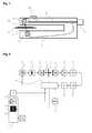
- FIG. 1shows the structure of the device according to the invention with its fork-shaped housing 1.
- the lower leg of the ultrasonic transmitting transducer 2is housed in the upper leg of the ultrasonic receiving transducer 3.
- the two legsare arranged in parallel and the distance between them forms the gap through which the carrier material can be guided.
- Transmitting and receiving transducersform the measuring section 7 and are connected to the transmitter 4.
- indicator lights and a button 8are connected to the transmitter 4.
- the connection 5 with plug for the output signal and possibly a control inputis in turn connected directly to the transmitter 4.
- the carrier material 6is guided with the labels 9.
- the carrier material with the labelsmoves out of the projection surface in the direction of the observer.
- In the plane of the projection surface of the transmitting and receiving transducersare inclined slightly obliquely. A suitable angle is 13 ° from the surface normal of the carrier material 6.
- the ultrasonic transmitting transducer 2radiates time-discrete sound pulses. These stimulate the carrier material to vibrate. As a result, an attenuated sound wave is emitted on the opposite side, which is received by the ultrasonic receiving transducer 3.
- the transmitter 4evaluates the received signals of the measuring section 7 and enters result-dependent output signal on plug 5 off. This can be a simple logic signal or even a signal on a digital interface.
- FIG. 2shows the block diagram of the transmitter with transmit and receive transducers.
- the entire measurement sequenceis controlled by an arithmetic unit 16, which is designed for example as a microcontroller or microprocessor.
- the arithmetic unitgives a start pulse to the ultrasound generator 10.
- the power output stage 11may consist of a transformer which generates a high voltage from the output signal of the generator, or of a push-pull output stage, for example constructed with transistors.
- the ultrasonic transmitting transducer 2emits a short sound pulse. This excites the carrier material 6 to oscillate, so that on the opposite side of the carrier material 6, a small sound wave is emitted. This sound wave is received by the ultrasonic receiving transducer 3 and amplified in an AC amplifier 12.
- the amplification factor of the AC amplifier 12can be set by the calculating unit 16.
- the amplified received signalis passed through a bandpass filter 13 to filter out noise and spurious signals.
- the amplified and filtered received signalis then rectified in a rectifier 14, wherein the rectifier includes a small smoothing capacitor, so that at the output of the rectifier, the envelope of the received signal is present.
- This envelopeis digitized with a fast analog-to-digital converter 15 and read in the arithmetic unit 16. If a microcontroller with integrated analog-to-digital converter is used as the arithmetic unit, this integrated analog-to-digital converter can also be used if it is fast enough. If necessary, between the rectifier 14 and the analog-to-digital converter 15 still a sample and hold stage can be switched. This then has the task to temporarily store the voltage value of the envelope, so that a slower analog-to-digital converter can pick up the value.
- the calculating unit 16evaluates the received measured values and controls the output signal 18 in accordance with the result.
- the outputis typically implemented as a binary switching element in semiconductor technology, such as a pnp switching output, an npn switching output or a push-pull output stage.
- the userVia a button 8 on the housing 1 or a control input 19 on the terminal 5, the user can set the device to the scanned substrate 6 with the specific labels 9. This is necessary because there are very diverse carrier materials and labels that can deliver very different signal levels.
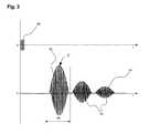
- FIG. 3shows the received signal of a single measurement and the envelope 43 obtained therefrom.
- the transmit converter 2emits a short transmit pulse packet.
- the first directly received transmission signal 41 in the evaluation window 44is shown.
- the first directly received transmission signal 41is followed by further received signals 42.
- Of interestis exclusively the first directly received transmission signal 41, since only this signal contains the information about the signal attenuation caused by carrier material 6 and labels 9.
- the arithmetic unitcan define an evaluation window 44 on the time axis in which it only the first directly received transmission signal 41 receives and evaluates.
- the arithmetic unitselects the largest value from the received measured values in the evaluation window 44 and stores this as an intermediate result Z. Since the first directly received transmission signal 41 following received signals 42 are no longer taken into account by the calculator, affect this caused by multiple reflections and overlays, unwanted Signals are not the actual measurement. With increasing ultrasonic frequency, the attenuation in the air increases quadratically.
- the ultrasonic frequency for the transmit and receive transducersis selected to be 500 kHz so high that individual measurements are possible every 100 ⁇ s. Furthermore, a high ultrasonic frequency has the advantage that the actual measuring spot on the carrier material becomes very small. Thanks to the combination of the individual measurements with pulsed transmission signals and a high ultrasonic frequency, the use of diaphragms in front of the ultrasonic transducers can be dispensed with. An even higher ultrasonic frequency is even more advantageous.
- the calculatorperforms these individual measurements at very short intervals and determines the intermediate result Z for each individual measurement.
- the time interval between two individual measurementscan be set by the arithmetic unit and varies between 100 ⁇ s and 2 ms. With a very thin carrier or web material only very little sound power is needed. In correspondingly short time intervals, the individual measurements can be performed. The faster the individual measurements can be made, the faster the device can react. If, however, thicker carrier or web materials are scanned, it may be necessary to increase the radiated sound power so that transmission still takes place. Since more power is then applied to the ultrasonic transmitting transducer, the individual measurements must be carried out in a longer time interval in order to avoid an overload of the transmitting transducer. Therefore, the device automatically adjusts the duration of the individual measurements to the power given to the transmitting transducer. This avoids overloading the transmitting transducer.
- the deviceSince there are many different carrier materials and labels, the device must be set to the material to be scanned. This is done by a teach-in process. This learning process can be triggered manually on the device via the button 8 or alternatively externally from the Control via a control input 19 at connection 5.
- Labels and carrier materialcan be taught in either statically or dynamically.
- the static teach-in processaccording to FIG. 4 initially only the carrier material 6 is inserted into the fork. About the button 8 or via a pulse at the control input 19 on the plug 5 of the static teach-in process is initiated. Indicators signal to the user that the teach-in process has been started. With an inhomogeneous substrate, the user should move the substrate a little back and forth in the fork so that the device can detect the different signal levels 30.
- the arithmetic unitvaries the amplification factor of the amplifier 12 until the received signal level lies in the desired range, in this example approximately 150.
- the arithmetic unitcan additionally shorten the length of the emitted transmitted pulse. For this purpose, it shortens the enable signal for the generator 10. From all values of the individual measurements for the carrier material (6), the smallest and largest values are temporarily stored temporarily. With a short press on the button 8 or a short pulse on the control input 19 at the terminal 5 of the learning process for the carrier material is completed. The user then places the carrier material with label in the fork. With a further keystroke on the button 8 or a short pulse at the control input 19 at the terminal 5 of the learning process for carrier material is started with label.
- the usercan again move carrier material with label back and forth, so that the device can detect the inhomogeneities in the waveform 30. From all values of the individual measurements for the carrier material with object 9, the smallest and largest values are temporarily also temporarily stored. One last press of the button 8 or a last short pulse on the control input 19 at the terminal 5 completes the static learning process. If the smallest value of the carrier material is greater than the largest value of the objects, the smallest value A1 of the carrier material and the largest value A2 of the objects is transferred to the EEPROM 17 If the largest value of the carrier material is smaller than the smallest value of the objects, the largest value A2 of the carrier material and the smallest value A1 of the objects are taken over into the EEPROM 17. The arithmetic unit determines the discriminator value MW from the values A1 and A2 and stores it non-volatilely in the EEPROM 17.
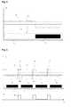
- FIG. 4shows the waveform 30 of the time discrete recorded intermediate results Z from the evaluation window 44 during a static training process.
- a carrier material 6 with a label 9 located thereonis shown schematically below the signal course.
- the substrateprovides a value of about 150-160 and label with carrier signal levels in the range of 93-107.
- FIG. 4are additionally drawn to the waveform 30 in the static learning process on the substrate and on the labels determined smallest value of the substrate A1 and the largest value of the labels A2.
- the static teach-in processprovides the optimal discriminator value MW even for critical materials, where the found values A1 and A2 can be very close to each other.
- the carrier material with the labelscan also be taught in dynamically.
- a drive devicemust pull the carrier material through the device at a constant speed.
- the calculatorvaries the gain of the amplifier 12 until the received signal levels for the large ones Intermediate values Z in the evaluation windows (35) in the desired range, here in the example at approx. 150, lie.
- the arithmetic unitcan additionally shorten the length of the emitted transmission pulses and adapt the duration of a single measurement of the power accordingly.
- first evaluation windows 35are set up, within which the lowest value A1 of the received signal for the carrier material 6 is determined, and second evaluation windows 34 are spanned, within which the highest value of the A2 received signal for the carrier material with object 9 is determined, which is used to calculate the Discriminator MW be used.
- FIG. 5shows the typical waveform of the time-discrete recorded intermediate results Z during a dynamic learning process.
- a carrier material 6 with labels 9 located thereonis shown schematically below the signal curve.
- the labelsare moved through the device at a constant speed.
- the lowest value of the carrier material A1 determined on the carrier material and on the labels during the dynamic teach-in process and the largest value of the labels A2are shown.
- the arithmetic unitIn order to be able to determine the smallest value of the carrier material A1 and the largest value of carrier material with labels A2 during the dynamic teach-in process, the arithmetic unit must in the time waveform 30 evaluate the evaluation windows 34 for determining A2 and the evaluation windows 35 for determining A1 on the time-discrete Apply recorded intermediate results Z. Thus, the edge changes of carrier material on Carrier material with label and vice versa hidden. For this purpose, the time-discrete recorded intermediate results Z are temporarily stored in the arithmetic unit and then analyzed by it numerically.
- Fig. 5Furthermore, the generated output signal 18 is shown over time. It follows the signal curve 30 as it exceeds the discriminator value 30 or below.
- the microprocessorcan recognize whether carrier material and labels are to be taught static or dynamic. For example, dynamic teach-in can be initiated with a push of 3 s and static teach-in with a push of 6 s.
- the signal value of the carrier materialis determined automatically by a teach-in and closed back to the signal value for carrier material with labels, but rather in the teach-in operations, the signal values for carrier material and carrier material with labels are determined separately and by an arithmetic Calculation of discriminator MW derived from it.
- the output signal 18would only be output in an inverted manner.
- the output characteristic of the signal outputcan optionally be inverted, ie switched between normally closed and normally closed switching behavior, via a keystroke sequence on the push-button 8 or via a signal sequence at the control input 19 at the connection 5.
Landscapes
- Physics & Mathematics (AREA)
- Acoustics & Sound (AREA)
- Health & Medical Sciences (AREA)
- Life Sciences & Earth Sciences (AREA)
- Chemical & Material Sciences (AREA)
- Analytical Chemistry (AREA)
- Biochemistry (AREA)
- General Health & Medical Sciences (AREA)
- General Physics & Mathematics (AREA)
- Immunology (AREA)
- Pathology (AREA)
- Length Measuring Devices Characterised By Use Of Acoustic Means (AREA)
Abstract
Description
Translated fromGermanDie Erfindung bezieht sich auf eine Vorrichtung zur Detektion von auf einem Trägermaterial befindlichen flachen Objekten mit einem Ultraschall-Sendewandler und einem Ultraschall-Empfangswandler, die ein Messstrecke bilden, wobei das Trägermaterial mit den flachen Objekten in der Messstrecke bewegt wird, und mit einer Auswerteelektronik, die an einem elektrischen Anschluss ein Ausgangssignal über detektierte Objekte auf dem Trägermaterial liefert, wobei über die Auswerteelektronik aus dem Ultraschall-Sendewandler kurze Schallimpulse abgestrahlt werden, die über die Messstrecke nach einer Transmission durch das Trägermaterial mit oder ohne Objekt zum Ultraschall-Empfangswandler gelangen, als Empfangssignal über einen Analog-Digital-Umsetzer in die Auswerteelektronik eingelesen werden und in Abhängigkeit von in einem Auswertefenster eingelesenen Werten das Ausgangssignal gesteuert wird.The invention relates to a device for detecting flat objects located on a carrier material with an ultrasonic transmitting transducer and an ultrasonic receiving transducer, which form a measuring path, wherein the carrier material is moved with the flat objects in the measuring path, and with evaluation electronics, which at an electrical connection provides an output signal on detected objects on the carrier material, being emitted via the transmitter from the ultrasonic transmitting transducer short sound pulses that pass through the measuring path after a transmission through the substrate with or without object to the ultrasonic receiving transducer, as Receive signal are read via an analog-to-digital converter in the transmitter and the output signal is controlled in response to read in an evaluation window values.
In den Herstellprozessen von Papier oder Folie werden diese als Endlosbahn gefertigt und auf eine Rolle aufgewickelt. Kommt es in den Herstellprozessen zu einer Unterbrechung der Materialbahn, wird die neue Materialbahn mit einem so genannten Spleiß an das Ende der Materialbahn angeklebt und das Bahnmaterial wird weiter aufgewickelt. Das Ankleben, auch Spleißen genannt, einer neuen Materialbahn an das Ende der alten Materialbahn erfolgt entweder mit einem doppelseitigen Klebestreifen oder mit einem entsprechend breiten Klebeband. Werden diese Papierrollen oder Folienrollen später weiterverarbeitet, zum Beispiel um aus dem Papier Verpackungen herzustellen, müssen diese Spleiße, die sich irgendwo auf der Materialbahn befinden können, detektiert werden.
Produkte, wie zum Beispiel Zigarettenschachteln oder CDs, werden häufig in eine transparente Folie eingeschlagen. Diese Folien sind dann mit einem so genannten Aufreißfaden ausgestattet, mit dem der Benutzer die Folie leicht von dem Produkt entfernen kann. An einer Verpackungsmaschine, die Produkte mit einer derartigen Folie einschlägt, besteht die Aufgabe, die Anwesenheit und korrekte Position des Aufreißfadens zu überwachen.In the manufacturing processes of paper or film, these are manufactured as a continuous web and wound up on a roll. If there is an interruption of the material web in the production processes, the new material web is glued to the end of the material web with a so-called splice and the web material continues to be wound up. The gluing, also called splicing, of a new material web to the end of the old material web takes place either with a double-sided adhesive strip or with a correspondingly wide adhesive tape. If these paper rolls or film rolls are processed further later, for example to produce packaging from the paper, these splices, which can be located anywhere on the material web, must be detected.
Products, such as cigarette packets or CDs, are often wrapped in a transparent film. These films are then provided with a so-called tear thread, with which the user can easily remove the film from the product. On a packaging machine that strikes products with such a film, the task is to monitor the presence and correct position of the tear thread.
Viele Produkte und dessen Verpackungen werden im Herstellungsprozess mit einem Aufkleber oder Etikett versehen. Diese Etiketten befinden sich zunächst auf einem Trägermaterial, welches auf eine Rolle aufgerollt ist. So genannte Etikettiermaschinen oder Etikettierer nehmen die Etiketten vom Trägermaterial ab und bringen diese auf das Produkt oder dessen Verpackung vollautomatisch auf. Für diesen Etikettiervorgang muss die Etikette auf dem Trägermaterial erkannt werden. Hierfür werden Etikettensensoren eingesetzt, die optisch im Durchlichtverfahren oder kapazitiv arbeiten. Die optischen Sensoren im Durchlichtverfahren versagen, wenn die Etiketten transparent oder lichtundurchlässig sind. Kapazitive Etikettensensoren können nicht bei metallisierten Etiketten eingesetzt werden und reagieren sehr empfindlich auf Schwankungen in der Luftfeuchtigkeit.Many products and their packaging are labeled or labeled in the manufacturing process. These labels are initially on a carrier material, which is rolled up on a roll. So-called labeling machines or labelers remove the labels from the carrier material and apply them fully automatically to the product or its packaging. For this labeling process, the label must be recognized on the carrier material. For this purpose, label sensors are used which operate optically in the transmitted light method or capacitively. The transmitted-light optical sensors fail if the labels are transparent or opaque. Capacitive label sensors can not be used with metallized labels and are very sensitive to fluctuations in humidity.
Eine interessante Alternative sind Etikettensensoren basierend auf Ultraschall. Ultraschall hat den Vorteil, dass dieser farbunabhängig arbeitet und auch bei hochtransparenten, lichtundurchlässigen und auch bei metallisierten Etiketten eingesetzt werden kann.
Den unterschiedlichen Wirkprinzipien gemeinsam ist die verbreitete Gehäusebauform als Gabelsensor. Ein Gabelsensor besteht aus jeweils einem oberen und unteren Schenkel, die in einem definierten Abstand zueinander angeordnet sind. Zwischen den beiden Schenkeln befindet sich ein Spalt, durch den das Trägermaterial mit den Etiketten hindurchgezogen wird. In den Schenkeln befinden sich die Ultraschallwandler und die Auswerteelektronik. Durch diesen Spalt können auch Bahnmaterialen zur Erkennung von Spleißen, bzw. transparente Folien zur Erkennung von Aufreißfäden gezogen werden.
Im Folgenden wird nur von Trägermaterial gesprochen. Mit diesem Merkmal sind auch Bahnmaterial und Folien mit erfasst.An interesting alternative is label sensors based on ultrasound. Ultrasound has the advantage that it works independently of color and can also be used in highly transparent, opaque and metallized labels.
Common to the different operating principles is the widespread housing design as a fork sensor. A fork sensor consists of a respective upper and lower leg, which are arranged at a defined distance from each other. Between the two legs there is a gap through which the carrier material is pulled with the labels. The thighs contain the ultrasonic transducers and the evaluation electronics. Through this gap also web materials for the detection of splices, or transparent films for the detection of tear threads can be drawn.
The following is only spoken about carrier material. This feature also includes web material and films.
In der Patentschrift
Praktische Versuche haben nun gezeigt, dass sehr dünne Etiketten/Spleiße, wenn sie auf einem dicken Trägermaterial geklebt sind, einen nur sehr geringen Signalunterschied zum Trägermaterial aufweisen können. Es wurden sogar Etiketten/Spleiße gefunden, die auf dem Trägermaterial einen höheren Signalpegel lieferten als das Trägermaterial alleine.
Bezogen auf dem Signalpegel des Trägermaterials kann ein Etikett auf dem Trägermaterial Signalwerte liefern, die nur bei 80 % liegen, also nur 20 % unter dem Signalpegel des Trägermaterials.
Zieht man nur den Spitzenwert des Trägermaterials zur Bestimmung des Schwellenwerts heran, kann man Etiketten mit einem sehr geringen Signalunterschied zum Trägermaterial nicht abtasten. Eine Abtastung von Etiketten, die einen höheren Signalpegel liefern als das Trägermaterial alleine, ist mit dieser Vorrichtung gar nicht möglich. Bei einem porösen, sehr schalldurchlässigen Trägermaterial kann der Spitzenwert des Trägermaterials einen extrem hohen Wert annehmen, so dass von diesem Wert gar nicht mehr auf den abgeschwächten Wert einer Etikette geschlossen werden kann.
Der Patentschrift ist zu entnehmen, dass es sich bei dem Sendesignal um ein frequenzmoduliertes Dauerstrichsignal handelt. Ein Dauerstrichsignal hat den Nachteil, dass es aufgrund von Mehrfachreflexionen des Schalls zwischen den Schenkeln der Gabel, bzw. zwischen den Schenkeln und dem Trägermaterial zu Überlagerung und Interferenzen des Empfangssignals kommt.Practical experiments have now shown that very thin labels / splices, when adhered to a thick substrate, can have only a very small signal difference from the substrate. Even labels / splices were found that provided a higher signal level on the substrate than the substrate alone.
Based on the signal level of the carrier material, a label on the carrier material can deliver signal values that are only 80%, ie only 20% below the signal level of the carrier material.
If one uses only the peak value of the carrier material for the determination of the threshold value, one can not scan labels with a very small signal difference to the carrier material. A scan of labels that provide a higher signal level than the substrate alone, is not possible with this device. In the case of a porous, very sound-permeable carrier material, the peak value of the carrier material can assume an extremely high value, so that it is no longer possible to conclude from this value on the attenuated value of a label.
It can be seen from the patent specification that the transmission signal is a frequency-modulated continuous wave signal. A continuous wave signal has the disadvantage that due to multiple reflections of the sound between the legs of the fork, or between the legs and the carrier material to interference and interference of the received signal.
Die Offenlegungsschrift
Der Erfindung liegt die Aufgabe zu Grunde, mit einer Vorrichtung auch Etiketten detektieren zu können, die nur einen sehr geringen Signalunterschied zwischen Trägermaterial und Trägermaterial mit Etiketten liefern und die Etiketten auch dann noch sicher erkennen kann, wenn diese einen größeren Signalpegel liefern als das Trägermaterial alleine. Dabei sollen nicht nur Etiketten, sondern auch andere flache Objekte wie Spleiße oder Aufrei ßfäden auf einem Trägermaterial erkannt werden.
Auch sollen Objekte noch sicher erkannt werden können, wenn diese auf einem porösen und schalldurchlässigen Trägermaterial aufgebracht sind.
Weiter soll auf den Einsatz von zusätzlichen Blenden verzichtet werden und gleichzeitig soll die Ansprechzeit für die Erkennung einer Etikette deutlich verkürzt werden.The invention is based on the object to be able to detect labels with a device that provide only a very small signal difference between the carrier material and carrier material with labels and the labels can still reliably recognize even if they provide a greater signal level than the substrate alone , It should not only labels, but also other flat objects such as splices or Aufrei ßfäden be recognized on a substrate.
Also, objects can still be reliably detected if they are applied to a porous and sound-permeable substrate.
Furthermore, the use of additional diaphragms should be dispensed with and, at the same time, the response time for the detection of a label should be significantly shortened.
Die Lösung dieser Aufgaben wird durch eine Vorrichtung mit den Merkmalen des Anspruch1 erreicht. Der zugehörige Einlernvorgang wird nach den Verfahren gemäß Anspruch 8 oder 9 durchgeführt.
Vorteilhafte Ausgestaltungen der Vorrichtung sind in den Unteransprüchen beschrieben.The solution of these objects is achieved by a device having the features of
Advantageous embodiments of the device are described in the subclaims.
Die Vorrichtung zur Detektion von flachen Objekten, die sich auf einem Trägermaterial befinden, erfolgt mit einem Ultraschall-Sendewandler und einem Ultraschall-Empfangswandler, die eine Messstrecke bilden. Das Trägermaterial mit den Objekten wird in der Messstrecke bewegt und mit einer Auswerteelektronik bewertet, die an einem elektrischen Anschluss ein Ausgangssignal über detektierte Objekte auf dem Trägermaterial liefert. Dabei werden über die Auswerteelektronik aus dem Ultraschall-Sendewandler Schallimpulse abgestrahlt, die über die Messstrecke nach einer Transmission durch das Trägermaterial mit oder ohne Objekt zum Ultraschall-Empfangswandler gelangen. Diese Empfangssignale werden über einen Analog-Digital-Umsetzer innerhalb eines Auswertefensters in ein Rechenwerk der Auswerteelektronik eingelesen und in Abhängigkeit von in eingelesenen Werten das Ausgangssignal gesteuert.The device for the detection of flat objects, which are located on a carrier material, takes place with an ultrasonic transmitting transducer and an ultrasonic receiving transducer, which form a measuring path. The carrier material with the objects is moved in the measuring section and evaluated with evaluation electronics which deliver an output signal via detected objects on the carrier material at an electrical connection. In this case, sound pulses are emitted via the evaluation electronics from the ultrasonic transmitting transducer, which pass through the measuring path after transmission through the carrier material with or without an object to the ultrasonic receiving transducer. These received signals are converted into an arithmetic unit via an analog-to-digital converter within an evaluation window read in the evaluation and controlled in dependence on read in the output signal.
Die Vorrichtung zeichnet sich dadurch aus, dass die Schallimpulse kurze Pulspakete sind, die in einem ersten Auswertefenster als Einzelmessung bewertet werden und dass während eines Einlernvorgangs aus den eingelesenen Werten der Einzelmessungen aus der Menge der größten Werte der niedrigste Wert A1 und aus der Menge der kleinsten Werte der höchste Wert A2 bestimmt wird und aus diesen Werten ein Diskriminatorwert für die Einzelmessungen bestimmt wird, bei dessen Unter- oder Überschreiten das Ausgangssignal wechselt.
So können bei verschienen Kombinationen von Objekten und Trägermaterial diese sicher auseinandergehalten werden.The device is characterized in that the sound pulses are short pulse packets, which are evaluated in a first evaluation window as a single measurement and that during a learning process from the read values of the individual measurements from the set of the largest values of the lowest value A1 and from the amount of the smallest Values the highest value A2 is determined and from these values a discriminator value is determined for the individual measurements, the undershoot or exceeding the output signal changes.
Thus, in various combinations of objects and carrier material these can be safely kept apart.
Die hier beschriebene Vorrichtung ist nicht nur für die Detektion von Etiketten nutzbar. Die Objekte können auch Spleiße auf dem Trägermaterial sein. Ebenso sind Aufreißfäden von Verpackungen, etwa Zigarettenschachteln oder CD-Hüllen, durch die Vorrichtung detektierbar.The device described here can not only be used for the detection of labels. The objects can also be splices on the substrate. Likewise, tear threads of packages, such as cigarette packs or CD cases, are detectable by the device.
Die Vorrichtung ist vorteilhaft in einem gabelförmigen Gehäuse mit zwei Schenkeln untergebracht. Dabei befinden sich der Ultraschall-Sendewandler in dem unteren Schenkel und der Ultraschall-Empfangswandler in dem oberen Schenkel. Beide sind unter einem Winkel in die Schenkel eingebaut, so dass sich eine schräggestellte Messtrecke zwischen ihnen ergibt.
Ebenso ist die Auswertelektronik in einem der Schenkel untergebracht. Auch der elektrische Anschluss der Vorrichtung ist am Gehäuse angebracht.The device is advantageously housed in a fork-shaped housing with two legs. In this case, the ultrasonic transmitting transducer in the lower leg and the ultrasonic receiving transducer in the upper leg. Both are installed at an angle in the legs, so that there is an inclined measuring distance between them.
Likewise, the evaluation electronics is housed in one of the legs. The electrical connection of the device is also attached to the housing.
Der für die Bestimmung des Diskriminatorwertes vorgesehene Einlernvorgang kann über einen Steuereingang am elektrischen Anschluss oder einen Taster am Gehäuse ausgelöst werden.The learning process provided for determining the discriminator value can be triggered via a control input on the electrical connection or a push-button on the housing.
Das Ausgangssignal ist ein digitales Logiksignal, das von einer nachgeordneten Maschinensteuerung ausgewertet werden kann. Durch eine Signalfolge am Steuereingang des elektrischen Anschlusses oder eine Tastendruckkombination am Taster ist das Ausgangssignal auch invertierbar.The output signal is a digital logic signal that can be evaluated by a downstream machine controller. By a signal sequence at the control input of the electrical connection or a key press combination The output signal is also invertible on the button.
Die Vorrichtung wird anhand der Figuren für die Detektion von Etiketten weiter erläutert.
Figur 1Figur 2Figur 3 zeigt das typische Empfangssignal einer einzelnen Messung.Figur 4 zeigt den Signalverlauf der zeitdiskret aufgenommenen Messwerte bei einem statischen Einlernvorgang.Figur 5
FIG. 1 shows a cross section through the housing of the device.FIG. 2 shows the block diagram of the evaluation of the device.FIG. 3 shows the typical received signal of a single measurement.FIG. 4 shows the signal curve of the discrete-time recorded measured values during a static teach-in process.FIG. 5 shows the waveform of discrete-time recorded measured values in a dynamic learning process.
Durch den Spalt, gebildet aus dem oberen und unteren Schenkel des Gehäuses, wird das Trägermaterial 6 mit den Etiketten 9 geführt. Das Trägermaterial mit den Etiketten bewegt sich aus der Projektionsfläche in Richtung des Betrachters. In der Ebene der Projektionsfläche sind der Sende-und der Empfangswandler etwas schräg geneigt. Ein geeigneter Winkel beträgt 13° aus der Flächennormale des Trägermaterials 6.
Through the gap, formed from the upper and lower legs of the housing, the
Der Ultraschall-Sendewandler 2 strahlt zeitdiskret Schallimpulse ab. Diese regen das Trägermaterial zu Schwingungen an. Hierdurch wird auf der gegenüberliegenden Seite eine abgeschwächte Schallwelle abgestrahlt, die vom Ultraschall-Empfangswandler 3 empfangen wird. Die Auswerteelektronik 4 wertet die empfangenen Signale der Messstrecke 7 aus und gibt ein ergebnisabhängiges Ausgangssignal an Stecker 5 aus. Dies kann ein einfaches logisches Signal oder aber auch ein Signal an einer digitalen Schnittstelle sein.
Der Verstärkungsfaktor des Wechselspannungsverstärkers 12 kann vom Rechenwerk 16 eingestellt werden. Das verstärkte Empfangssignal wird über einen Bandpass 13 geführt, um Rauschen und Störsignale herauszufiltern. Das verstärkte und gefilterte Empfangssignal wird anschließend in einem Gleichrichter 14 gleichgerichtet, wobei der Gleichrichter einen kleiner Glättungskondensator enthält, so dass an dem Ausgang des Gleichrichters die Einhüllende des Empfangssignals ansteht.
Diese Einhüllende wird mit einem schnellen Analog-Digital-Umsetzer 15 digitalisiert und im Rechenwerk 16 eingelesen. Wird als Rechenwerk ein Mikrocontroller mit integriertem Analog-Digital-Umsetzer verwendet, kann auch dieser integrierte Analog-Digital-Umsetzer verwendet werden, sofern dieser schnell genug ist. Bei Bedarf kann zwischen dem Gleichrichter 14 und dem Analog-Digital-Umsetzer 15 noch eine Sample & Hold-Stufe geschaltet werden. Diese hat dann die Aufgabe, den Spannungswert der Einhüllende zwischenzuspeichern, so dass ein langsamer Analog-Digital-Umsetzer den Wert abholen kann.The
The amplification factor of the AC amplifier 12 can be set by the calculating unit 16. The amplified received signal is passed through a
This envelope is digitized with a fast analog-to-digital converter 15 and read in the arithmetic unit 16. If a microcontroller with integrated analog-to-digital converter is used as the arithmetic unit, this integrated analog-to-digital converter can also be used if it is fast enough. If necessary, between the rectifier 14 and the analog-to-digital converter 15 still a sample and hold stage can be switched. This then has the task to temporarily store the voltage value of the envelope, so that a slower analog-to-digital converter can pick up the value.
Das Rechenwerk 16 bewertet die empfangenen Messwerte und steuert entsprechend dem Ergebnis das Ausgangssignal 18 an. Der Ausgang ist in der Regel als ein binäres Schaltelement in Halbleitertechnik, wie zum Beispiel ein pnp-Schaltausgang, ein npn-Schaltausgang oder eine Push-pull-Endstufe, ausgeführt.The calculating unit 16 evaluates the received measured values and controls the
Über einen Taster 8 am Gehäuse 1 oder einen Steuereingang 19 am Anschluss 5 kann der Anwender die Vorrichtung auf das abzutastende Trägermaterial 6 mit den spezifischen Etiketten 9 einstellen. Dies ist notwendig, da es sehr vielfältige Trägermaterialien und Etiketten gibt, die sehr unterschiedliche Signalpegel liefern können.Via a button 8 on the
Da das Rechenwerk zum Zeitpunkt 0 das Abstrahlen des Sendepulspaketes 40 generiert und der Abstand zwischen den beiden Schenkeln, respektive zwischen dem Ultraschall-Sende- 2 und Ultraschall-Empfangswandler 3 bekannt ist, kann das Rechenwerk auf der Zeitachse ein Auswertefenster 44 festlegen, in dem er nur das erste direkt empfange Transmissionssignal 41 empfängt und auswertet. Das Rechenwerk sucht sich im Auswertefenster 44 aus den empfangenen Messwerten den größten Wert heraus und speichert diesen als Zwischenergebnis Z ab. Da die dem ersten direkt empfangen Transmissionssignal 41 folgenden Empfangssignale 42 von dem Rechenwerk nicht mehr berücksichtigt werden, beeinflussen diese durch Mehrfachreflexionen und Überlagerungen entstandenen, unerwünschten Signale die eigentliche Messung nicht.
Mit steigender Ultraschallfrequenz nimmt die Dämpfung in der Luft quadratisch zu. Je höher die gewählte Ultraschallfrequenz ist, umso schneller ist der Schall absorbiert und man kann mit der nächsten Einzelmessung früher starten. Die Ultraschallfrequenz für den Sende- und Empfangswandler wird mit 500 kHz so hoch gewählt, dass Einzelmessungen bereits alle 100 µs möglich sind. Weiter hat eine hohe Ultraschallfrequenz den Vorteil, dass der eigentliche Messfleck auf dem Trägermaterial sehr klein wird. Dank der Kombination der Einzelmessungen mit gepulsten Sendesignalen und einer hohen Ultraschallfrequenz kann auf den Einsatz von Blenden vor den Ultraschallwandlern verzichtet werden. Eine noch höhere Ultraschallfrequenz ist noch vorteilhafter.Since the arithmetic unit at the time 0 generates the emission of the
With increasing ultrasonic frequency, the attenuation in the air increases quadratically. The higher the selected ultrasonic frequency, the faster the sound is absorbed and you can start earlier with the next single measurement. The ultrasonic frequency for the transmit and receive transducers is selected to be 500 kHz so high that individual measurements are possible every 100 μs. Furthermore, a high ultrasonic frequency has the advantage that the actual measuring spot on the carrier material becomes very small. Thanks to the combination of the individual measurements with pulsed transmission signals and a high ultrasonic frequency, the use of diaphragms in front of the ultrasonic transducers can be dispensed with. An even higher ultrasonic frequency is even more advantageous.
Das Rechenwerk führt in sehr kurzen Zeitabständen diese Einzelmessungen durch und ermittelt für jede Einzelmessung das Zwischenergebnis Z. Der zeitliche Abstand zwischen zwei Einzelmessungen kann vom Rechenwerk eingestellt werden und variiert zwischen 100 µs und 2 ms. Bei einem sehr dünnen Träger- oder Bahnmaterial wird nur sehr wenig Schallleistung benötigt. In entsprechend kurzen Zeitabständen können die Einzelmessungen durchgeführt werden. Je schneller die Einzelmessungen durchgeführt werden können, umso schneller kann die Vorrichtung reagieren. Werden jedoch dickere Träger- oder Bahnmaterialien abgetastet, muss unter Umständen die abgestrahlte Schallleistung erhöht werden, damit noch eine Transmission stattfindet. Da dann mehr Leistung auf den Ultraschall-Sendewandler gegeben wird, müssen die Einzelmessungen in einem längeren Zeitabstand durchgeführt werden, um eine Überlastung des Sendewandlers zu vermeiden. Deshalb passt die Vorrichtung die Dauer der Einzelmessungen automatisch der auf den Sendewandler gegebenen Leistung an. Damit wird eine Überlastung des Sendewandlers vermieden.The calculator performs these individual measurements at very short intervals and determines the intermediate result Z for each individual measurement. The time interval between two individual measurements can be set by the arithmetic unit and varies between 100 μs and 2 ms. With a very thin carrier or web material only very little sound power is needed. In correspondingly short time intervals, the individual measurements can be performed. The faster the individual measurements can be made, the faster the device can react. If, however, thicker carrier or web materials are scanned, it may be necessary to increase the radiated sound power so that transmission still takes place. Since more power is then applied to the ultrasonic transmitting transducer, the individual measurements must be carried out in a longer time interval in order to avoid an overload of the transmitting transducer. Therefore, the device automatically adjusts the duration of the individual measurements to the power given to the transmitting transducer. This avoids overloading the transmitting transducer.
Da es sehr viele unterschiedliche Trägermaterialien und Etiketten gibt, muss die Vorrichtung auf das abzutastende Material eingestellt werden. Dies geschieht durch einen Einlernvorgang. Dieser Einlernvorgang kann manuell an der Vorrichtung über den Taster 8 ausgelöst werden oder wahlweise extern von der Steuerung über einen Steuereingang 19 am Anschluss 5.Since there are many different carrier materials and labels, the device must be set to the material to be scanned. This is done by a teach-in process. This learning process can be triggered manually on the device via the button 8 or alternatively externally from the Control via a
Etiketten und Trägermaterial können wahlweise statisch oder dynamisch eingelernt werden.
Bei dem statischen Einlernvorgang gemäß
Aus allen Werten der Einzelmessungen für das Trägermaterials (6) werden der kleinste und größte Wert temporär zwischengespeichert.
Mit einem kurzen Druck auf die Taste 8 oder einem kurzen Impuls am Steuereingang 19 am Anschluss 5 wird der Einlernvorgang für das Trägermaterial abgeschlossen. Der Anwender legt anschließend das Trägermaterial mit Etikette in die Gabel ein. Mit einem weiteren Tastendruck auf den Taster 8 oder einem kurzen Impuls am Steuereingang 19 am Anschluss 5 wird der Einlernvorgang für Trägermaterial mit Etikette gestartet. Bei inhomogenen Materialien kann der Anwender wieder Trägermaterial mit Etikette hin und her bewegen, so dass die Vorrichtung die Inhomogenitäten im Signalverlauf 30 erfassen kann. Aus allen Werten der Einzelmessungen für das Trägermaterials mit Objekt 9 werden der kleinste und größte Wert temporär ebenfalls zwischengespeichert.
Ein letzter Tastendruck auf den Taster 8 bzw. ein letzter kurzer Impuls am Steuereingang 19 am Anschluss 5 schließt den statischen Einlernvorgang ab. Falls der kleinste Wert des Trägermaterials größer ist als der größte Wert der Objekte, werden der kleinste Wert A1 des Trägermaterials und der größte Wert A2 der Objekte in das EEPROM 17 übernommen wird
Falls der größte Wert des Trägermaterials kleiner ist als der kleinste Wert der Objekte, werden der größte Wert A2 des Trägermaterials und der kleinste Wert A1 der Objekte in das EEPROM 17 übernommen.
Das Rechenwerk ermittelt aus den Werten A1 und A2 den Diskriminatorwert MW und speichert diesen nichtflüchtig im EEPROM 17 ab.Labels and carrier material can be taught in either statically or dynamically.
In the static teach-in process according to
From all values of the individual measurements for the carrier material (6), the smallest and largest values are temporarily stored temporarily.
With a short press on the button 8 or a short pulse on the
One last press of the button 8 or a last short pulse on the
If the largest value of the carrier material is smaller than the smallest value of the objects, the largest value A2 of the carrier material and the smallest value A1 of the objects are taken over into the EEPROM 17.
The arithmetic unit determines the discriminator value MW from the values A1 and A2 and stores it non-volatilely in the EEPROM 17.
In
Der statische Einlernvorgang liefert den optimalen Diskriminatorwert MW auch bei kritischen Materialien, bei denen die gefundenen Werte A1 und A2 sehr nahe beieinander liegen können.In
The static teach-in process provides the optimal discriminator value MW even for critical materials, where the found values A1 and A2 can be very close to each other.
Ist das statische Einlernen für den Anwender nicht praktikabel, kann das Trägermaterial mit den Etiketten auch dynamisch eingelernt werden. Hierzu muss eine Antriebsvorrichtung das Trägermaterial mit einer konstanten Geschwindigkeit durch die Vorrichtung ziehen. Über einen Tastendruck am Taster 8 bzw. über einen Impuls am Steuereingang 19 am Anschluss 5 wird der dynamische Einlernvorgang initiiert. Während des Einlernvorgangs des Trägermaterials mit Etiketten variiert das Rechenwerk den Verstärkungsfaktor des Verstärkers 12 solange, bis die empfangenen Signalpegel für die großen Zwischenwerte Z in den Auswertefenstern (35) im gewünschten Bereich, hier im Beispiel bei ca. 150, liegen. Bei einem sehr "schalldurchlässigen" Trägermaterial kann das Rechenwerk zusätzlich die Länge der abgestrahlten Sendeimpulse verkürzen und die zeitliche Dauer einer Einzelmessung der Leistung entsprechend anpassen. Hierzu verkürzt er das Freigabesignal für den Generator 10.
Im Rechenwerk werden erste Auswertefenster 35 aufgespannt, innerhalb derer der niedrigste Wert A1 des Empfangssignals für das Trägermaterial 6 ermittelt wird, und zweite Auswertefenster 34 aufgespannt, innerhalb derer der höchste Wert des A2 Empfangssignals für das Trägermaterial mit Objekt 9 ermittelt wird, die zur Berechnung des Diskriminatorwertes MW herangezogen werden.
Mit einem weiteren Tastendruck am Taster 8 bzw. über einen Impuls am Steuereingang 19 am Anschluss 5 wird der dynamische Einlernvorgang abgeschlossen.If static teach-in is impractical for the user, the carrier material with the labels can also be taught in dynamically. For this purpose, a drive device must pull the carrier material through the device at a constant speed. By pressing a button on the button 8 or via a pulse at the
In the arithmetic unit,
With a further keystroke on the button 8 or via a pulse at the
Um während des dynamischen Einlernvorgangs den kleinsten Wert vom Trägermaterial A1 und den größten Wert von Trägermaterial mit Etiketten A2 ermitteln zu können, muss das Rechenwerk in dem zeitlichen Signalverlauf 30 die Auswertefenster 34 zur Ermittlung von A2 und die Auswertefenster 35 zur Ermittlung von A1 auf die zeitdiskret aufgenommenen Zwischenergebnisse Z anwenden. Damit werden die Flankenwechsel von Trägermaterial auf Trägermaterial mit Etikette und umgekehrt ausgeblendet. Hierzu werden die zeitdiskret aufgenommenen Zwischenergebnisse Z im Rechenwerk zwischengespeichert und anschließend von diesem numerisch analysiert.In order to be able to determine the smallest value of the carrier material A1 and the largest value of carrier material with labels A2 during the dynamic teach-in process, the arithmetic unit must in the
In
Über die Länge des ersten Tastendrucks am Taster 8, bzw. über die Länge des ersten Impulses am Steuereingang 19 am Anschluss 5 kann der Mikroprozessor erkennen, ob Trägermaterial und Etiketten statisch oder dynamisch eingelernt werden sollen. Ein dynamisches Einlernen kann zum Beispiel mit einem Tastendruck der Länge 3 s und ein statisches Einlernen mit einem Tastendruck der Länge 6 s initiiert werden.Over the length of the first key press on the button 8, or over the length of the first pulse at the
Gegenüber dem Stand der Technik wird hier nicht nur der Signalwert des Trägermaterials automatisch durch einen Einlernvorgang ermittelt und daraus rückwärts auf den Signalwert für Trägermaterial mit Etiketten geschlossen, sondern vielmehr werden in den Einlernvorgängen die Signalwerte für Trägermaterial und Trägermaterial mit Etiketten getrennt ermittelt und durch eine arithmetische Berechnung der Diskriminatorwert MW daraus abgeleitet.Compared to the prior art not only the signal value of the carrier material is determined automatically by a teach-in and closed back to the signal value for carrier material with labels, but rather in the teach-in operations, the signal values for carrier material and carrier material with labels are determined separately and by an arithmetic Calculation of discriminator MW derived from it.
Für beide Verfahren des Einlernens ist es unerheblich, ob Etiketten mit Trägermaterial einen höheren oder niedrigeren Signalpegel als das Trägermaterial alleine liefern. Liefern Etiketten mit Trägermaterial einen höheren Signalpegel, würde das Ausgangssignal 18 lediglich invertiert ausgegeben werden. Über eine Tastendruckfolge am Taster 8 bzw. über eine Signalfolge am Steuereingang 19 am Anschluss 5 kann die Ausgangscharakteristik des Signalausgangs optional invertiert werden, also zwischen Öffner- und Schließer-Schaltverhalten umgeschaltet werden.For both teach-in methods, it does not matter if labels with substrate provide a higher or lower signal level than the substrate alone. If labels with carrier material provide a higher signal level, the
- 11
- Gehäusecasing
- 22
- Ultraschall-SendewandlerUltrasonic transmitting transducer
- 33
- Ultraschall-EmpfangswandlerUltrasonic receiving transducer
- 44
- Auswerteelektronikevaluation
- 55
- Elektrischer Anschluss, zum Beispiel SteckerElectrical connection, for example plug
- 66
- Trägermaterial mit EtiketteCarrier material with label
- 77
- Messstreckemeasuring distance
- 88th
- Taster und LeuchtmelderPushbuttons and indicator lights
- 99
- Objekt, EtikettObject, label
- 1010
- Generatorgenerator
- 1111
- Leistungsendstufepower output stage
- 1212
- Analogverstärkeranalog amplifier
- 1313
- Bandpassbandpass
- 1414
- Gleichrichterrectifier
- 1515
- Analog-Digital-UmsetzerAnalog-to-digital converter
- 1616
- Rechenwerkcalculator
- 1717
- EEPROMEEPROM
- 1818
- Ausgangssignaloutput
- 1919
- Steuereingangcontrol input
- 3030
- Signalverlaufwaveform
- 3434
- Auswertefenster für die Ermittlung von A2Evaluation window for the determination of A2
- 3535
- Auswertefenster für die Ermittlung von A1Evaluation window for the determination of A1
- 4040
- Zeitpunkt Abstrahlen des SendeimpulsesTime emitting the transmitted pulse
- 4141
- Direkt empfangenes TransmissionssignalDirectly received transmission signal
- 4242
- Weitere empfangene TransmissionssignaleOther received transmission signals
- 4343
- Einhüllende nach GleichrichtungEnveloping after rectification
- 4444
- Erstes Auswertefenster bei der EinzelmessungFirst evaluation window for the single measurement
- A1A1
- kleinster Messwert vom Trägermaterialsmallest measured value of the carrier material
- A2A2
- größter Messwert von Etiketten mit Trägermateriallargest reading of labels with backing material
- MWMW
- Diskriminatorwertdiscriminator
- ZZ
- Zwischenergebnisinterim results
Claims (12)
Translated fromGermandie Schallimpulse kurze Pulspakete (40) sind, die in einem ersten Auswertefenster (44) als Einzelmessung bewertet werden,
und während eines Einlernvorgangs aus den eingelesenen Werten der Einzelmessungen aus der Menge der größten Werte der niedrigste Wert (A1) und aus der Menge der kleinsten Werte der höchste Wert (A2) bestimmt wird und aus diesen Werten ein Diskriminatorwert (MW) für die Einzelmessungen bestimmt wird, bei dessen Unter- oder Überschreiten das Ausgangssignal (18) wechselt.Device for detecting flat objects (9) located on a carrier material (6) with an ultrasound transmitting transducer (2) and an ultrasound receiving transducer (3) forming a measuring section (7), wherein the carrier material with the objects in the measuring section is moved, and with an evaluation, which at an electrical connection (5) provides an output signal (18) on detected objects on the substrate, wherein via the transmitter from the ultrasonic transmitting transducer (2) sound pulses are emitted over the measuring path ( 7) after transmission through the carrier material (6) with or without object to the ultrasonic receiving transducer (3), as received signal during an evaluation window (44) via an analog-to-digital converter (15) in an arithmetic unit (16) of the transmitter (4) are read in and the output signal (18) is controlled as a function of the read-in values,characterized in that
the sound pulses are short pulse packets (40) which are evaluated in a first evaluation window (44) as a single measurement,
and during a teach-in process from the read-in values of the individual measurements from the set of the largest values the lowest value (A1) and from the set of the smallest values the highest value (A2) is determined and from these values a discriminator value (MW) is determined for the individual measurements is at the under or over the output signal (18) changes.
beim dynamischen Einlernvorgang im Rechenwerk erste Auswertefenster (35) aufgespannt werden, innerhalb derer der niedrigste Wert (A1) des Empfangssignals für das Trägermaterial (6) ermittelt wird und zweite Auswertefenster (34) aufgespannt werden, innerhalb derer der höchste Wert des (A2) Empfangssignals für das Trägermaterial mit Objekt (9) ermittelt wird, die zur Berechnung des Diskriminatorwertes (MW) herangezogen werden.Method for carrying out a teaching process with a device according to claim 1,characterized in that
during the dynamic teach-in process in the arithmetic unit first evaluation window (35) be spanned within which the lowest value (A1) of the received signal for the carrier material (6) is determined and second evaluation window (34) are spanned, within which the highest value of the (A2) received signal for the carrier material with object (9) is determined , which are used to calculate the discriminator value (MW).
Priority Applications (1)
| Application Number | Priority Date | Filing Date | Title |
|---|---|---|---|
| EP11181019.8AEP2570354B8 (en) | 2011-09-13 | 2011-09-13 | Device for detecting flat objects on a carrier material |
Applications Claiming Priority (1)
| Application Number | Priority Date | Filing Date | Title |
|---|---|---|---|
| EP11181019.8AEP2570354B8 (en) | 2011-09-13 | 2011-09-13 | Device for detecting flat objects on a carrier material |
Publications (3)
| Publication Number | Publication Date |
|---|---|
| EP2570354A1true EP2570354A1 (en) | 2013-03-20 |
| EP2570354B1 EP2570354B1 (en) | 2016-03-16 |
| EP2570354B8 EP2570354B8 (en) | 2016-06-01 |
Family
ID=44582672
Family Applications (1)
| Application Number | Title | Priority Date | Filing Date |
|---|---|---|---|
| EP11181019.8AActiveEP2570354B8 (en) | 2011-09-13 | 2011-09-13 | Device for detecting flat objects on a carrier material |
Country Status (1)
| Country | Link |
|---|---|
| EP (1) | EP2570354B8 (en) |
Cited By (3)
| Publication number | Priority date | Publication date | Assignee | Title |
|---|---|---|---|---|
| FR3044103A1 (en)* | 2015-11-24 | 2017-05-26 | Schneider Electric Ind Sas | ULTRASONIC DETECTION SYSTEM |
| CN115667076A (en)* | 2020-05-28 | 2023-01-31 | Pe贴标机股份公司 | Container labelling machine |
| WO2024127239A1 (en)* | 2022-12-16 | 2024-06-20 | Georgia-Pacific Gypsum Llc | Adhesive backing detection systems and method |
Citations (5)
| Publication number | Priority date | Publication date | Assignee | Title |
|---|---|---|---|---|
| EP1067053B1 (en) | 1999-05-07 | 2002-11-20 | Leuze electronic GmbH + Co. | Device for detecting an object |
| DE10341436A1 (en)* | 2003-09-09 | 2005-03-31 | Leuze Electronic Gmbh & Co Kg | Ultrasonic transparent object structure sensor for paper strips carrying labels uses received noise dependent threshold to create binary presence signal |
| DE102008009578A1 (en)* | 2008-02-16 | 2009-09-17 | Leuze Electronic Gmbh + Co. Kg | Moving object detecting method for use on conveyor, involves adapting time-offsets of individual signal characteristics of sensor axles to running time of object, and generating object detection signal from total signal characteristics |
| EP2120067A1 (en)* | 2008-05-16 | 2009-11-18 | Leuze electronic GmbH + Co. KG | Sensor for detecting objects in a monitoring area |
| DE102008023185A1 (en) | 2008-05-10 | 2009-11-19 | Leuze Electronic Gmbh + Co. Kg | ultrasonic sensor |
- 2011
- 2011-09-13EPEP11181019.8Apatent/EP2570354B8/enactiveActive
Patent Citations (5)
| Publication number | Priority date | Publication date | Assignee | Title |
|---|---|---|---|---|
| EP1067053B1 (en) | 1999-05-07 | 2002-11-20 | Leuze electronic GmbH + Co. | Device for detecting an object |
| DE10341436A1 (en)* | 2003-09-09 | 2005-03-31 | Leuze Electronic Gmbh & Co Kg | Ultrasonic transparent object structure sensor for paper strips carrying labels uses received noise dependent threshold to create binary presence signal |
| DE102008009578A1 (en)* | 2008-02-16 | 2009-09-17 | Leuze Electronic Gmbh + Co. Kg | Moving object detecting method for use on conveyor, involves adapting time-offsets of individual signal characteristics of sensor axles to running time of object, and generating object detection signal from total signal characteristics |
| DE102008023185A1 (en) | 2008-05-10 | 2009-11-19 | Leuze Electronic Gmbh + Co. Kg | ultrasonic sensor |
| EP2120067A1 (en)* | 2008-05-16 | 2009-11-18 | Leuze electronic GmbH + Co. KG | Sensor for detecting objects in a monitoring area |
Cited By (5)
| Publication number | Priority date | Publication date | Assignee | Title |
|---|---|---|---|---|
| FR3044103A1 (en)* | 2015-11-24 | 2017-05-26 | Schneider Electric Ind Sas | ULTRASONIC DETECTION SYSTEM |
| EP3173345A1 (en) | 2015-11-24 | 2017-05-31 | Schneider Electric Industries SAS | Ultrasonic detection system |
| US10228461B2 (en) | 2015-11-24 | 2019-03-12 | Schneider Electric Industries Sas | Ultrasonic detection system |
| CN115667076A (en)* | 2020-05-28 | 2023-01-31 | Pe贴标机股份公司 | Container labelling machine |
| WO2024127239A1 (en)* | 2022-12-16 | 2024-06-20 | Georgia-Pacific Gypsum Llc | Adhesive backing detection systems and method |
Also Published As
| Publication number | Publication date |
|---|---|
| EP2570354B1 (en) | 2016-03-16 |
| EP2570354B8 (en) | 2016-06-01 |
Similar Documents
| Publication | Publication Date | Title |
|---|---|---|
| DE112009005380B4 (en) | Obstacle detection device | |
| DE102017120682A1 (en) | DEVICE AND METHOD FOR OPERATING AN ULTRASOUND SENSOR | |
| DE102004061759B4 (en) | Method and device for non-contact detection of layered flat objects | |
| DE2642633A1 (en) | LOCKING DEVICE | |
| WO1986002913A1 (en) | Method for detecting the position of the band edge of a material sheet | |
| DE19842250A1 (en) | Method for determining the distance between an object and a locally changing device, in particular a motor vehicle | |
| EP0641679A1 (en) | Apparatus for monitoring the tyre pressure of a vehicle comprising a sensor | |
| DE2257510A1 (en) | METHOD AND EQUIPMENT FOR MEASURING THE TENSION OF A TAPE | |
| EP0721907A2 (en) | Ultrasonic edge sensor for detecting the edge of a material web | |
| EP2570354B1 (en) | Device for detecting flat objects on a carrier material | |
| DE2338849B2 (en) | Device for finding surface defects on continuously moving web or strip material | |
| EP0305780A1 (en) | Method and apparatus for error reduction in the measurement of the spatial movement of points to be measured by means of ultrasonic signals | |
| EP0553446B2 (en) | Method for detecting impurities, especially foreign fibres in elongated textile articles | |
| WO2006007826A1 (en) | Method and device for the non-destructive and contactless detection of flaws in a test piece moved relative to a probe | |
| EP2769949A1 (en) | Method for using measurement technology to differentiate between material zones in the form of a sheet, a web or sheet-like material and device for same | |
| DE3639228C2 (en) | ||
| EP0158022A1 (en) | Method and circuit arrangement for monitoring the operation of ultrasonic alarm systems | |
| DE3126160C2 (en) | ||
| DE2907904A1 (en) | METHOD AND DEVICE FOR MEASURING THE RELATIONSHIP BETWEEN THE TENSION AND THE BASIS WEIGHT OF A RAIL-SHAPED MATERIAL | |
| US4169399A (en) | Electronic device for controlling the function of an electronic yarn clearer | |
| EP1058087A1 (en) | Position recording of an edge with distributed sensors by determining the turning point | |
| DE20312388U1 (en) | Contactless detector for detecting thickness irregularities in flat objects, measures amplitude of transmitted ultrasound wave and measures reflected signals from both sides to determine thickness | |
| EP1953685B1 (en) | Device for counting printing products in a layer transport flow | |
| AT513852B1 (en) | Method for determining the layer thickness of a bonding layer between two packaging layers | |
| CN100361164C (en) | Automatic transaction machine double sheet detector |
Legal Events
| Date | Code | Title | Description |
|---|---|---|---|
| PUAI | Public reference made under article 153(3) epc to a published international application that has entered the european phase | Free format text:ORIGINAL CODE: 0009012 | |
| 17P | Request for examination filed | Effective date:20120314 | |
| AK | Designated contracting states | Kind code of ref document:A1 Designated state(s):AL AT BE BG CH CY CZ DE DK EE ES FI FR GB GR HR HU IE IS IT LI LT LU LV MC MK MT NL NO PL PT RO RS SE SI SK SM TR | |
| AX | Request for extension of the european patent | Extension state:BA ME | |
| 17Q | First examination report despatched | Effective date:20141208 | |
| RIC1 | Information provided on ipc code assigned before grant | Ipc:G01N 29/11 20060101ALI20150819BHEP Ipc:B65H 26/02 20060101ALI20150819BHEP Ipc:B65H 43/00 20060101ALI20150819BHEP Ipc:B65C 9/42 20060101AFI20150819BHEP | |
| GRAP | Despatch of communication of intention to grant a patent | Free format text:ORIGINAL CODE: EPIDOSNIGR1 | |
| INTG | Intention to grant announced | Effective date:20150928 | |
| GRAS | Grant fee paid | Free format text:ORIGINAL CODE: EPIDOSNIGR3 | |
| GRAA | (expected) grant | Free format text:ORIGINAL CODE: 0009210 | |
| AK | Designated contracting states | Kind code of ref document:B1 Designated state(s):AL AT BE BG CH CY CZ DE DK EE ES FI FR GB GR HR HU IE IS IT LI LT LU LV MC MK MT NL NO PL PT RO RS SE SI SK SM TR | |
| REG | Reference to a national code | Ref country code:GB Ref legal event code:FG4D Free format text:NOT ENGLISH | |
| REG | Reference to a national code | Ref country code:CH Ref legal event code:EP | |
| REG | Reference to a national code | Ref country code:IE Ref legal event code:FG4D Free format text:LANGUAGE OF EP DOCUMENT: GERMAN | |
| REG | Reference to a national code | Ref country code:AT Ref legal event code:REF Ref document number:780986 Country of ref document:AT Kind code of ref document:T Effective date:20160415 Ref country code:CH Ref legal event code:NV Representative=s name:RIEDERER HASLER AND PARTNER PATENTANWAELTE AG, LI | |
| REG | Reference to a national code | Ref country code:DE Ref legal event code:R096 Ref document number:502011009088 Country of ref document:DE | |
| REG | Reference to a national code | Ref country code:DE Ref legal event code:R082 Ref document number:502011009088 Country of ref document:DE Representative=s name:TARVENKORN & WICKORD PATENTANWAELTE PARTNERSCH, DE Ref country code:DE Ref legal event code:R081 Ref document number:502011009088 Country of ref document:DE Owner name:MICROSONIC GMBH, DE Free format text:FORMER OWNER: MICROSONIC GESELLSCHAFT FUER MIKROELEKTRONIK UND ULLTRASCHALLTECHNIK MBH, 44227 DORTMUND, DE | |
| RAP2 | Party data changed (patent owner data changed or rights of a patent transferred) | Owner name:MICROSONIC GMBH | |
| REG | Reference to a national code | Ref country code:CH Ref legal event code:PUE Owner name:MICROSONIC GMBH, DE Free format text:FORMER OWNER: MICROSONIC GESELLSCHAFT FUER MIKROELEKTRONIK UND ULLTRASCHALLTECHNIK MBH, DE | |
| REG | Reference to a national code | Ref country code:NL Ref legal event code:FP | |
| REG | Reference to a national code | Ref country code:CH Ref legal event code:NV Representative=s name:RIEDERER HASLER AND PARTNER PATENTANWAELTE AG, LI | |
| REG | Reference to a national code | Ref country code:LT Ref legal event code:MG4D | |
| PG25 | Lapsed in a contracting state [announced via postgrant information from national office to epo] | Ref country code:HR Free format text:LAPSE BECAUSE OF FAILURE TO SUBMIT A TRANSLATION OF THE DESCRIPTION OR TO PAY THE FEE WITHIN THE PRESCRIBED TIME-LIMIT Effective date:20160316 Ref country code:NO Free format text:LAPSE BECAUSE OF FAILURE TO SUBMIT A TRANSLATION OF THE DESCRIPTION OR TO PAY THE FEE WITHIN THE PRESCRIBED TIME-LIMIT Effective date:20160616 Ref country code:FI Free format text:LAPSE BECAUSE OF FAILURE TO SUBMIT A TRANSLATION OF THE DESCRIPTION OR TO PAY THE FEE WITHIN THE PRESCRIBED TIME-LIMIT Effective date:20160316 | |
| REG | Reference to a national code | Ref country code:AT Ref legal event code:HC Ref document number:780986 Country of ref document:AT Kind code of ref document:T Owner name:MICROSONIC GMBH, DE Effective date:20160623 | |
| PG25 | Lapsed in a contracting state [announced via postgrant information from national office to epo] | Ref country code:LV Free format text:LAPSE BECAUSE OF FAILURE TO SUBMIT A TRANSLATION OF THE DESCRIPTION OR TO PAY THE FEE WITHIN THE PRESCRIBED TIME-LIMIT Effective date:20160316 Ref country code:LT Free format text:LAPSE BECAUSE OF FAILURE TO SUBMIT A TRANSLATION OF THE DESCRIPTION OR TO PAY THE FEE WITHIN THE PRESCRIBED TIME-LIMIT Effective date:20160316 Ref country code:SE Free format text:LAPSE BECAUSE OF FAILURE TO SUBMIT A TRANSLATION OF THE DESCRIPTION OR TO PAY THE FEE WITHIN THE PRESCRIBED TIME-LIMIT Effective date:20160316 Ref country code:RS Free format text:LAPSE BECAUSE OF FAILURE TO SUBMIT A TRANSLATION OF THE DESCRIPTION OR TO PAY THE FEE WITHIN THE PRESCRIBED TIME-LIMIT Effective date:20160316 | |
| REG | Reference to a national code | Ref country code:NL Ref legal event code:HC Owner name:MICROSONIC GMBH; DE Free format text:DETAILS ASSIGNMENT: VERANDERING VAN EIGENAAR(S), VERANDERING VAN NAAM VAN DE EIGENAAR(S); FORMER OWNER NAME: MICROSONIC GESELLSCHAFT FUER MIKROELEKTRONIK UND ULLTRASCHALLTECHNIK MBH Effective date:20160613 | |
| REG | Reference to a national code | Ref country code:FR Ref legal event code:PLFP Year of fee payment:6 | |
| PG25 | Lapsed in a contracting state [announced via postgrant information from national office to epo] | Ref country code:IS Free format text:LAPSE BECAUSE OF FAILURE TO SUBMIT A TRANSLATION OF THE DESCRIPTION OR TO PAY THE FEE WITHIN THE PRESCRIBED TIME-LIMIT Effective date:20160716 Ref country code:PL Free format text:LAPSE BECAUSE OF FAILURE TO SUBMIT A TRANSLATION OF THE DESCRIPTION OR TO PAY THE FEE WITHIN THE PRESCRIBED TIME-LIMIT Effective date:20160316 Ref country code:EE Free format text:LAPSE BECAUSE OF FAILURE TO SUBMIT A TRANSLATION OF THE DESCRIPTION OR TO PAY THE FEE WITHIN THE PRESCRIBED TIME-LIMIT Effective date:20160316 | |
| PG25 | Lapsed in a contracting state [announced via postgrant information from national office to epo] | Ref country code:SK Free format text:LAPSE BECAUSE OF FAILURE TO SUBMIT A TRANSLATION OF THE DESCRIPTION OR TO PAY THE FEE WITHIN THE PRESCRIBED TIME-LIMIT Effective date:20160316 Ref country code:ES Free format text:LAPSE BECAUSE OF FAILURE TO SUBMIT A TRANSLATION OF THE DESCRIPTION OR TO PAY THE FEE WITHIN THE PRESCRIBED TIME-LIMIT Effective date:20160316 Ref country code:SM Free format text:LAPSE BECAUSE OF FAILURE TO SUBMIT A TRANSLATION OF THE DESCRIPTION OR TO PAY THE FEE WITHIN THE PRESCRIBED TIME-LIMIT Effective date:20160316 Ref country code:CZ Free format text:LAPSE BECAUSE OF FAILURE TO SUBMIT A TRANSLATION OF THE DESCRIPTION OR TO PAY THE FEE WITHIN THE PRESCRIBED TIME-LIMIT Effective date:20160316 Ref country code:PT Free format text:LAPSE BECAUSE OF FAILURE TO SUBMIT A TRANSLATION OF THE DESCRIPTION OR TO PAY THE FEE WITHIN THE PRESCRIBED TIME-LIMIT Effective date:20160718 Ref country code:RO Free format text:LAPSE BECAUSE OF FAILURE TO SUBMIT A TRANSLATION OF THE DESCRIPTION OR TO PAY THE FEE WITHIN THE PRESCRIBED TIME-LIMIT Effective date:20160316 | |
| REG | Reference to a national code | Ref country code:DE Ref legal event code:R097 Ref document number:502011009088 Country of ref document:DE | |
| PG25 | Lapsed in a contracting state [announced via postgrant information from national office to epo] | Ref country code:IT Free format text:LAPSE BECAUSE OF FAILURE TO SUBMIT A TRANSLATION OF THE DESCRIPTION OR TO PAY THE FEE WITHIN THE PRESCRIBED TIME-LIMIT Effective date:20160316 | |
| PLBE | No opposition filed within time limit | Free format text:ORIGINAL CODE: 0009261 | |
| STAA | Information on the status of an ep patent application or granted ep patent | Free format text:STATUS: NO OPPOSITION FILED WITHIN TIME LIMIT | |
| PG25 | Lapsed in a contracting state [announced via postgrant information from national office to epo] | Ref country code:DK Free format text:LAPSE BECAUSE OF FAILURE TO SUBMIT A TRANSLATION OF THE DESCRIPTION OR TO PAY THE FEE WITHIN THE PRESCRIBED TIME-LIMIT Effective date:20160316 | |
| 26N | No opposition filed | Effective date:20161219 | |
| PG25 | Lapsed in a contracting state [announced via postgrant information from national office to epo] | Ref country code:BE Free format text:LAPSE BECAUSE OF NON-PAYMENT OF DUE FEES Effective date:20160930 Ref country code:BG Free format text:LAPSE BECAUSE OF FAILURE TO SUBMIT A TRANSLATION OF THE DESCRIPTION OR TO PAY THE FEE WITHIN THE PRESCRIBED TIME-LIMIT Effective date:20160616 | |
| PG25 | Lapsed in a contracting state [announced via postgrant information from national office to epo] | Ref country code:MC Free format text:LAPSE BECAUSE OF FAILURE TO SUBMIT A TRANSLATION OF THE DESCRIPTION OR TO PAY THE FEE WITHIN THE PRESCRIBED TIME-LIMIT Effective date:20160316 | |
| PG25 | Lapsed in a contracting state [announced via postgrant information from national office to epo] | Ref country code:SI Free format text:LAPSE BECAUSE OF FAILURE TO SUBMIT A TRANSLATION OF THE DESCRIPTION OR TO PAY THE FEE WITHIN THE PRESCRIBED TIME-LIMIT Effective date:20160316 | |
| REG | Reference to a national code | Ref country code:IE Ref legal event code:MM4A | |
| PG25 | Lapsed in a contracting state [announced via postgrant information from national office to epo] | Ref country code:IE Free format text:LAPSE BECAUSE OF NON-PAYMENT OF DUE FEES Effective date:20160913 | |
| PG25 | Lapsed in a contracting state [announced via postgrant information from national office to epo] | Ref country code:LU Free format text:LAPSE BECAUSE OF NON-PAYMENT OF DUE FEES Effective date:20160913 | |
| REG | Reference to a national code | Ref country code:FR Ref legal event code:PLFP Year of fee payment:7 | |
| REG | Reference to a national code | Ref country code:BE Ref legal event code:MM Effective date:20160930 | |
| PG25 | Lapsed in a contracting state [announced via postgrant information from national office to epo] | Ref country code:CY Free format text:LAPSE BECAUSE OF FAILURE TO SUBMIT A TRANSLATION OF THE DESCRIPTION OR TO PAY THE FEE WITHIN THE PRESCRIBED TIME-LIMIT Effective date:20160316 Ref country code:HU Free format text:LAPSE BECAUSE OF FAILURE TO SUBMIT A TRANSLATION OF THE DESCRIPTION OR TO PAY THE FEE WITHIN THE PRESCRIBED TIME-LIMIT; INVALID AB INITIO Effective date:20110913 | |
| PG25 | Lapsed in a contracting state [announced via postgrant information from national office to epo] | Ref country code:MK Free format text:LAPSE BECAUSE OF FAILURE TO SUBMIT A TRANSLATION OF THE DESCRIPTION OR TO PAY THE FEE WITHIN THE PRESCRIBED TIME-LIMIT Effective date:20160316 Ref country code:MT Free format text:LAPSE BECAUSE OF FAILURE TO SUBMIT A TRANSLATION OF THE DESCRIPTION OR TO PAY THE FEE WITHIN THE PRESCRIBED TIME-LIMIT Effective date:20160316 Ref country code:TR Free format text:LAPSE BECAUSE OF FAILURE TO SUBMIT A TRANSLATION OF THE DESCRIPTION OR TO PAY THE FEE WITHIN THE PRESCRIBED TIME-LIMIT Effective date:20160316 Ref country code:GR Free format text:LAPSE BECAUSE OF FAILURE TO SUBMIT A TRANSLATION OF THE DESCRIPTION OR TO PAY THE FEE WITHIN THE PRESCRIBED TIME-LIMIT Effective date:20160316 | |
| REG | Reference to a national code | Ref country code:FR Ref legal event code:PLFP Year of fee payment:8 | |
| PG25 | Lapsed in a contracting state [announced via postgrant information from national office to epo] | Ref country code:AL Free format text:LAPSE BECAUSE OF FAILURE TO SUBMIT A TRANSLATION OF THE DESCRIPTION OR TO PAY THE FEE WITHIN THE PRESCRIBED TIME-LIMIT Effective date:20160316 | |
| PG25 | Lapsed in a contracting state [announced via postgrant information from national office to epo] | Ref country code:IT Free format text:LAPSE BECAUSE OF FAILURE TO SUBMIT A TRANSLATION OF THE DESCRIPTION OR TO PAY THE FEE WITHIN THE PRESCRIBED TIME-LIMIT Effective date:20160316 | |
| PGRI | Patent reinstated in contracting state [announced from national office to epo] | Ref country code:IT Effective date:20190204 | |
| P01 | Opt-out of the competence of the unified patent court (upc) registered | Effective date:20230601 | |
| REG | Reference to a national code | Ref country code:DE Ref legal event code:R082 Ref document number:502011009088 Country of ref document:DE Representative=s name:WICKORD BUSER PATENTANWAELTE PARTG MBB, DE | |
| PGFP | Annual fee paid to national office [announced via postgrant information from national office to epo] | Ref country code:DE Payment date:20240926 Year of fee payment:14 | |
| PGFP | Annual fee paid to national office [announced via postgrant information from national office to epo] | Ref country code:GB Payment date:20240923 Year of fee payment:14 | |
| PGFP | Annual fee paid to national office [announced via postgrant information from national office to epo] | Ref country code:FR Payment date:20240930 Year of fee payment:14 | |
| PGFP | Annual fee paid to national office [announced via postgrant information from national office to epo] | Ref country code:NL Payment date:20240920 Year of fee payment:14 | |
| PGFP | Annual fee paid to national office [announced via postgrant information from national office to epo] | Ref country code:AT Payment date:20240918 Year of fee payment:14 | |
| PGFP | Annual fee paid to national office [announced via postgrant information from national office to epo] | Ref country code:IT Payment date:20240930 Year of fee payment:14 | |
| PGFP | Annual fee paid to national office [announced via postgrant information from national office to epo] | Ref country code:CH Payment date:20241001 Year of fee payment:14 |