EP2568937B1 - Self contained illuminated infusion cannula system - Google Patents
Self contained illuminated infusion cannula systemDownload PDFInfo
- Publication number
- EP2568937B1 EP2568937B1EP11721202.7AEP11721202AEP2568937B1EP 2568937 B1EP2568937 B1EP 2568937B1EP 11721202 AEP11721202 AEP 11721202AEP 2568937 B1EP2568937 B1EP 2568937B1
- Authority
- EP
- European Patent Office
- Prior art keywords
- lumen
- cannula
- light
- led
- cannula system
- Prior art date
- Legal status (The legal status is an assumption and is not a legal conclusion. Google has not performed a legal analysis and makes no representation as to the accuracy of the status listed.)
- Not-in-force
Links
- 238000001802infusionMethods0.000titledescription69
- 239000012530fluidSubstances0.000claimsdescription59
- 238000004891communicationMethods0.000claimsdescription9
- 238000009826distributionMethods0.000claimsdescription3
- 210000001508eyeAnatomy0.000description59
- 230000003287optical effectEffects0.000description38
- 239000003978infusion fluidSubstances0.000description30
- 238000001356surgical procedureMethods0.000description25
- 238000005286illuminationMethods0.000description24
- 238000000034methodMethods0.000description22
- 239000000463materialSubstances0.000description17
- 210000003786scleraAnatomy0.000description16
- 239000000835fiberSubstances0.000description15
- 238000002834transmittanceMethods0.000description13
- 238000003780insertionMethods0.000description11
- 230000037431insertionEffects0.000description11
- 230000008901benefitEffects0.000description9
- 239000006185dispersionSubstances0.000description9
- 210000005252bulbus oculiAnatomy0.000description8
- 230000006870functionEffects0.000description8
- 238000007789sealingMethods0.000description7
- 230000008859changeEffects0.000description6
- 230000008569processEffects0.000description6
- 238000003860storageMethods0.000description6
- 230000007704transitionEffects0.000description6
- 238000004519manufacturing processMethods0.000description5
- 239000012780transparent materialSubstances0.000description5
- 230000005540biological transmissionEffects0.000description4
- 239000003086colorantSubstances0.000description4
- BHEPBYXIRTUNPN-UHFFFAOYSA-Nhydridophosphorus(.) (triplet)Chemical compound[PH]BHEPBYXIRTUNPN-UHFFFAOYSA-N0.000description4
- 239000010410layerSubstances0.000description4
- 230000007246mechanismEffects0.000description4
- 229920001296polysiloxanePolymers0.000description4
- 238000012795verificationMethods0.000description4
- 239000004952PolyamideSubstances0.000description3
- NIXOWILDQLNWCW-UHFFFAOYSA-Nacrylic acid groupChemical groupC(C=C)(=O)ONIXOWILDQLNWCW-UHFFFAOYSA-N0.000description3
- 230000008878couplingEffects0.000description3
- 238000010168coupling processMethods0.000description3
- 238000005859coupling reactionMethods0.000description3
- 230000003247decreasing effectEffects0.000description3
- 230000001419dependent effectEffects0.000description3
- 230000000694effectsEffects0.000description3
- 230000004410intraocular pressureEffects0.000description3
- 239000000314lubricantSubstances0.000description3
- 229920002647polyamidePolymers0.000description3
- 229920000515polycarbonatePolymers0.000description3
- 239000004417polycarbonateSubstances0.000description3
- 238000012545processingMethods0.000description3
- 230000004044responseEffects0.000description3
- 239000003566sealing materialSubstances0.000description3
- 238000004026adhesive bondingMethods0.000description2
- 238000004458analytical methodMethods0.000description2
- 210000003484anatomyAnatomy0.000description2
- 238000004364calculation methodMethods0.000description2
- 239000011247coating layerSubstances0.000description2
- 238000000576coating methodMethods0.000description2
- 238000013461designMethods0.000description2
- 230000009365direct transmissionEffects0.000description2
- 238000001746injection mouldingMethods0.000description2
- 230000003993interactionEffects0.000description2
- 238000003754machiningMethods0.000description2
- 238000012986modificationMethods0.000description2
- 230000004048modificationEffects0.000description2
- 210000001747pupilAnatomy0.000description2
- 239000004065semiconductorSubstances0.000description2
- 238000001228spectrumMethods0.000description2
- 239000000126substanceSubstances0.000description2
- 238000002604ultrasonographyMethods0.000description2
- 230000000007visual effectEffects0.000description2
- 238000012800visualizationMethods0.000description2
- 241001631457CannulaSpecies0.000description1
- FAPWRFPIFSIZLT-UHFFFAOYSA-MSodium chlorideChemical compound[Na+].[Cl-]FAPWRFPIFSIZLT-UHFFFAOYSA-M0.000description1
- 239000000853adhesiveSubstances0.000description1
- 230000001070adhesive effectEffects0.000description1
- 238000013459approachMethods0.000description1
- 238000003491arrayMethods0.000description1
- 210000004204blood vesselAnatomy0.000description1
- 239000000969carrierSubstances0.000description1
- 210000003161choroidAnatomy0.000description1
- 230000001143conditioned effectEffects0.000description1
- 238000011109contaminationMethods0.000description1
- 238000005520cutting processMethods0.000description1
- 230000001627detrimental effectEffects0.000description1
- 238000006073displacement reactionMethods0.000description1
- 238000005401electroluminescenceMethods0.000description1
- 238000005516engineering processMethods0.000description1
- 230000004907fluxEffects0.000description1
- 230000017525heat dissipationEffects0.000description1
- 239000007943implantSubstances0.000description1
- 238000009434installationMethods0.000description1
- 239000004973liquid crystal related substanceSubstances0.000description1
- 238000007726management methodMethods0.000description1
- 238000012978minimally invasive surgical procedureMethods0.000description1
- 238000000465mouldingMethods0.000description1
- 230000006855networkingEffects0.000description1
- 210000001328optic nerveAnatomy0.000description1
- 238000005457optimizationMethods0.000description1
- 210000000056organAnatomy0.000description1
- 230000008520organizationEffects0.000description1
- 230000000399orthopedic effectEffects0.000description1
- 238000004806packaging method and processMethods0.000description1
- 230000037361pathwayEffects0.000description1
- 230000000149penetrating effectEffects0.000description1
- 230000002093peripheral effectEffects0.000description1
- 238000004382pottingMethods0.000description1
- 230000009467reductionEffects0.000description1
- 239000012858resilient materialSubstances0.000description1
- 230000000284resting effectEffects0.000description1
- 210000001525retinaAnatomy0.000description1
- 239000011780sodium chlorideSubstances0.000description1
- 239000010409thin filmSubstances0.000description1
- 238000001429visible spectrumMethods0.000description1
Images


Classifications
- A—HUMAN NECESSITIES
- A61—MEDICAL OR VETERINARY SCIENCE; HYGIENE
- A61F—FILTERS IMPLANTABLE INTO BLOOD VESSELS; PROSTHESES; DEVICES PROVIDING PATENCY TO, OR PREVENTING COLLAPSING OF, TUBULAR STRUCTURES OF THE BODY, e.g. STENTS; ORTHOPAEDIC, NURSING OR CONTRACEPTIVE DEVICES; FOMENTATION; TREATMENT OR PROTECTION OF EYES OR EARS; BANDAGES, DRESSINGS OR ABSORBENT PADS; FIRST-AID KITS
- A61F9/00—Methods or devices for treatment of the eyes; Devices for putting in contact-lenses; Devices to correct squinting; Apparatus to guide the blind; Protective devices for the eyes, carried on the body or in the hand
- A61F9/0008—Introducing ophthalmic products into the ocular cavity or retaining products therein
- A61F9/0017—Introducing ophthalmic products into the ocular cavity or retaining products therein implantable in, or in contact with, the eye, e.g. ocular inserts
- A—HUMAN NECESSITIES
- A61—MEDICAL OR VETERINARY SCIENCE; HYGIENE
- A61B—DIAGNOSIS; SURGERY; IDENTIFICATION
- A61B3/00—Apparatus for testing the eyes; Instruments for examining the eyes
- A61B3/0008—Apparatus for testing the eyes; Instruments for examining the eyes provided with illuminating means
- A—HUMAN NECESSITIES
- A61—MEDICAL OR VETERINARY SCIENCE; HYGIENE
- A61B—DIAGNOSIS; SURGERY; IDENTIFICATION
- A61B1/00—Instruments for performing medical examinations of the interior of cavities or tubes of the body by visual or photographical inspection, e.g. endoscopes; Illuminating arrangements therefor
- A61B1/06—Instruments for performing medical examinations of the interior of cavities or tubes of the body by visual or photographical inspection, e.g. endoscopes; Illuminating arrangements therefor with illuminating arrangements
- A61B1/0661—Endoscope light sources
- A61B1/0684—Endoscope light sources using light emitting diodes [LED]
- A—HUMAN NECESSITIES
- A61—MEDICAL OR VETERINARY SCIENCE; HYGIENE
- A61B—DIAGNOSIS; SURGERY; IDENTIFICATION
- A61B1/00—Instruments for performing medical examinations of the interior of cavities or tubes of the body by visual or photographical inspection, e.g. endoscopes; Illuminating arrangements therefor
- A61B1/06—Instruments for performing medical examinations of the interior of cavities or tubes of the body by visual or photographical inspection, e.g. endoscopes; Illuminating arrangements therefor with illuminating arrangements
- A61B1/07—Instruments for performing medical examinations of the interior of cavities or tubes of the body by visual or photographical inspection, e.g. endoscopes; Illuminating arrangements therefor with illuminating arrangements using light-conductive means, e.g. optical fibres
- A—HUMAN NECESSITIES
- A61—MEDICAL OR VETERINARY SCIENCE; HYGIENE
- A61B—DIAGNOSIS; SURGERY; IDENTIFICATION
- A61B1/00—Instruments for performing medical examinations of the interior of cavities or tubes of the body by visual or photographical inspection, e.g. endoscopes; Illuminating arrangements therefor
- A61B1/313—Instruments for performing medical examinations of the interior of cavities or tubes of the body by visual or photographical inspection, e.g. endoscopes; Illuminating arrangements therefor for introducing through surgical openings, e.g. laparoscopes
- A—HUMAN NECESSITIES
- A61—MEDICAL OR VETERINARY SCIENCE; HYGIENE
- A61B—DIAGNOSIS; SURGERY; IDENTIFICATION
- A61B17/00—Surgical instruments, devices or methods
- A61B17/02—Surgical instruments, devices or methods for holding wounds open, e.g. retractors; Tractors
- A61B17/0218—Surgical instruments, devices or methods for holding wounds open, e.g. retractors; Tractors for minimally invasive surgery
- A—HUMAN NECESSITIES
- A61—MEDICAL OR VETERINARY SCIENCE; HYGIENE
- A61B—DIAGNOSIS; SURGERY; IDENTIFICATION
- A61B17/00—Surgical instruments, devices or methods
- A61B17/02—Surgical instruments, devices or methods for holding wounds open, e.g. retractors; Tractors
- A61B17/0231—Surgical instruments, devices or methods for holding wounds open, e.g. retractors; Tractors for eye surgery
- A—HUMAN NECESSITIES
- A61—MEDICAL OR VETERINARY SCIENCE; HYGIENE
- A61B—DIAGNOSIS; SURGERY; IDENTIFICATION
- A61B17/00—Surgical instruments, devices or methods
- A61B17/34—Trocars; Puncturing needles
- A61B17/3417—Details of tips or shafts, e.g. grooves, expandable, bendable; Multiple coaxial sliding cannulas, e.g. for dilating
- A61B17/3421—Cannulas
- A61B17/3423—Access ports, e.g. toroid shape introducers for instruments or hands
- A—HUMAN NECESSITIES
- A61—MEDICAL OR VETERINARY SCIENCE; HYGIENE
- A61F—FILTERS IMPLANTABLE INTO BLOOD VESSELS; PROSTHESES; DEVICES PROVIDING PATENCY TO, OR PREVENTING COLLAPSING OF, TUBULAR STRUCTURES OF THE BODY, e.g. STENTS; ORTHOPAEDIC, NURSING OR CONTRACEPTIVE DEVICES; FOMENTATION; TREATMENT OR PROTECTION OF EYES OR EARS; BANDAGES, DRESSINGS OR ABSORBENT PADS; FIRST-AID KITS
- A61F9/00—Methods or devices for treatment of the eyes; Devices for putting in contact-lenses; Devices to correct squinting; Apparatus to guide the blind; Protective devices for the eyes, carried on the body or in the hand
- A61F9/0008—Introducing ophthalmic products into the ocular cavity or retaining products therein
- A61F9/0026—Ophthalmic product dispenser attachments to facilitate positioning near the eye
- A—HUMAN NECESSITIES
- A61—MEDICAL OR VETERINARY SCIENCE; HYGIENE
- A61F—FILTERS IMPLANTABLE INTO BLOOD VESSELS; PROSTHESES; DEVICES PROVIDING PATENCY TO, OR PREVENTING COLLAPSING OF, TUBULAR STRUCTURES OF THE BODY, e.g. STENTS; ORTHOPAEDIC, NURSING OR CONTRACEPTIVE DEVICES; FOMENTATION; TREATMENT OR PROTECTION OF EYES OR EARS; BANDAGES, DRESSINGS OR ABSORBENT PADS; FIRST-AID KITS
- A61F9/00—Methods or devices for treatment of the eyes; Devices for putting in contact-lenses; Devices to correct squinting; Apparatus to guide the blind; Protective devices for the eyes, carried on the body or in the hand
- A61F9/007—Methods or devices for eye surgery
- A61F9/00736—Instruments for removal of intra-ocular material or intra-ocular injection, e.g. cataract instruments
- A—HUMAN NECESSITIES
- A61—MEDICAL OR VETERINARY SCIENCE; HYGIENE
- A61B—DIAGNOSIS; SURGERY; IDENTIFICATION
- A61B17/00—Surgical instruments, devices or methods
- A61B17/34—Trocars; Puncturing needles
- A61B17/3417—Details of tips or shafts, e.g. grooves, expandable, bendable; Multiple coaxial sliding cannulas, e.g. for dilating
- A61B17/3421—Cannulas
- A—HUMAN NECESSITIES
- A61—MEDICAL OR VETERINARY SCIENCE; HYGIENE
- A61B—DIAGNOSIS; SURGERY; IDENTIFICATION
- A61B17/00—Surgical instruments, devices or methods
- A61B17/34—Trocars; Puncturing needles
- A61B17/3462—Trocars; Puncturing needles with means for changing the diameter or the orientation of the entrance port of the cannula, e.g. for use with different-sized instruments, reduction ports, adapter seals
- A—HUMAN NECESSITIES
- A61—MEDICAL OR VETERINARY SCIENCE; HYGIENE
- A61B—DIAGNOSIS; SURGERY; IDENTIFICATION
- A61B17/00—Surgical instruments, devices or methods
- A61B17/02—Surgical instruments, devices or methods for holding wounds open, e.g. retractors; Tractors
- A61B17/0218—Surgical instruments, devices or methods for holding wounds open, e.g. retractors; Tractors for minimally invasive surgery
- A61B2017/0225—Surgical instruments, devices or methods for holding wounds open, e.g. retractors; Tractors for minimally invasive surgery flexible, e.g. fabrics, meshes, or membranes
- A—HUMAN NECESSITIES
- A61—MEDICAL OR VETERINARY SCIENCE; HYGIENE
- A61B—DIAGNOSIS; SURGERY; IDENTIFICATION
- A61B90/00—Instruments, implements or accessories specially adapted for surgery or diagnosis and not covered by any of the groups A61B1/00 - A61B50/00, e.g. for luxation treatment or for protecting wound edges
- A61B90/30—Devices for illuminating a surgical field, the devices having an interrelation with other surgical devices or with a surgical procedure
- A61B2090/306—Devices for illuminating a surgical field, the devices having an interrelation with other surgical devices or with a surgical procedure using optical fibres
- A—HUMAN NECESSITIES
- A61—MEDICAL OR VETERINARY SCIENCE; HYGIENE
- A61B—DIAGNOSIS; SURGERY; IDENTIFICATION
- A61B90/00—Instruments, implements or accessories specially adapted for surgery or diagnosis and not covered by any of the groups A61B1/00 - A61B50/00, e.g. for luxation treatment or for protecting wound edges
- A61B90/30—Devices for illuminating a surgical field, the devices having an interrelation with other surgical devices or with a surgical procedure
- A61B2090/309—Devices for illuminating a surgical field, the devices having an interrelation with other surgical devices or with a surgical procedure using white LEDs
Definitions
- the present inventionrelates generally to medical surgery, and more particularly to cannula systems and more specifically, to an illuminated cannula device.
- Minimally invasive surgical proceduresutilize assorted systems and methods, such as endoscopes or the like, for observing a surgical site or a wound to enable a surgeon to perform various surgical procedures.
- the surgical fieldis observed through the pupil.
- Various medical tools, devices, instruments, or the likeare inserted into the vitreal cavity by performing a sclerotomy and/or other procedures to facilitate completion of the surgical procedure.
- the complexity of the ophthalmic surgeryincreases the duration of surgery and increases the number of support personnel required to assist the surgeon.
- Surgical procedure complexityis influenced by instrumentation introduced through various ports created by performing sclerotomies that are controlled by the surgeon.
- three portscan be created during a posterior operative surgical procedure, although additional or fewer ports can be created as necessary.
- the multiple portsprovide various functions for the surgical procedure.
- the multiple portsmaintain the intraocular pressure through fluid infusion of a fluid, air, oil, or gas, illuminate the interior of the eye via a light source, and provide a controlled access channel for inserting surgical instruments, devices, or the like.
- the systems and methods disclosed hereinare related to an illuminated infusion cannula for internally illuminating biological tissue, organs, body lumens, and/or body cavities to enable a surgeon to perform various orthopedic surgeries, neurosurgeries, and/or other surgical procedure.
- Various arrangements of the present disclosurecan also relate generally to an illuminated cannula device for internally illuminating an eye to enable a surgeon to perform various surgical procedures in, on, around, and/or near the eye.
- the present disclosureprovides a medical treatment system having a self-contained illuminated infusion cannula system, including a light source, such as a light emitting diode or an organic light emitting diode light source, located in the cannula device, and transmitting light and infusion fluid through the same cannula into the surgical site within the eyeball.
- a light sourcesuch as a light emitting diode or an organic light emitting diode light source
- a cannula systemcan include a body, a light source contained within the body, an infusion port and a cannula.
- the infusion portcan be formed in the body for receiving fluids to be delivered to a surgical site.
- the cannulacan also be formed with the body.
- the cannulacan have a lumen for delivering the fluids received through the infusion port and for transmitting light from the light source.
- the systemcan include one or more lens or other optical elements. Some arrangements may also or alternatively include a trocar sized to pass through the cannula.
- a cannula systemcan comprise a housing element having a lumen and a port configured to provide a flow of fluid to the lumen and a light emitting diode light source.
- the light sourcecan be positionable within the housing element and configured to direct light through the lumen when disposed within the housing element.
- the lumencan be transparent and configured to permit light to pass through the lumen from the light emitting diode light source to a surgical site.
- the lumencan also be configured to direct fluid to the surgical site.
- a cannula systemcan have a body, an insert and an elongate member.
- the bodycan have a proximal portion and a distal portion, a first lumen extending between the proximal portion and the distal portion, and a port coupled to a second lumen.
- the second lumencan communicate with the first lumen.
- the bodycan also have a first aperture extending to the first lumen at the proximal portion.
- the insert elementcan have a light source positionable within the first aperture to permit light from the light source to pass through the first lumen.
- the elongate membercan be transparent and can have a first portion and a second portion with a third lumen extending through the elongate member from the first portion to the second portion.
- the first portion of the elongate membercan be coupled to the distal portion of the first lumen.
- the transparent member third lumencan permit light to pass from the light source to a surgical site and be capable of fluid communication with the port, the first lumen, and the second lumen.
- a cannulacomprising a housing element having a distal portion and a proximal portion, a first lumen extending between the proximal portion and the distal portion, and a port capable of fluid communication with the first lumen.
- a light emitting diode light sourcecan be removably positionable within the housing element. The light emitting diode light source is configured to direct light through the first lumen when disposed within the housing.
- the light emitting diode light sourcecomprises at least a red light emitting diode, a blue light emitting diode, and a yellow light emitting diode.
- the arrangementfurther includes a transparent second lumen having a first portion and a second portion.
- the first portionis coupled to the distal portion of the first lumen, and the transparent second lumen is configured to permit light to pass through from the light emitting diode light source to a surgical site.
- the arrangementsadditionally includes the transparent second lumen being configured to receive fluid from the first lumen.
- the diameter of the transparent second lumenis 20 gauge or smaller.
- a cannulacomprising a housing element having a distal portion and a proximal portion, a first lumen extending between the proximal portion and the distal portion, and a port capable of fluid communication with the first lumen.
- a light emitting diode light sourcecan be removably positionable within the housing element. The light emitting diode light source is configured to direct light through the first lumen when disposed within the housing.
- the light emitting diode light sourcecomprises at least a red light emitting diode, a blue light emitting diode, and a yellow light emitting diode.
- the arrangementfurther includes a transparent second lumen having a first portion and a second portion.
- the first portionis coupled to the distal portion of the first lumen, and the transparent second lumen is configured to permit light to pass through from the light emitting diode light source to a surgical site.
- the arrangementadditionally includes the transparent second lumen being configured to receive fluid from the first lumen.
- the present disclosureprovides a cannula system comprising a body having a distal portion and a proximal portion, with a first lumen extending between the proximal portion and the distal portion and a periphery surface extending between the proximal portion and the distal portion.
- the arrangementfurther includes a port coupled to a second lumen. The second lumen communicating with the first lumen, and a first aperture extending to the first lumen.
- the arrangementcan additionally include an insert element comprising a light emitting diode light source positionable within the first aperture to permit light from the light emitting diode light source to pass through the first lumen.
- the arrangementstill further includes an elongate transparent member, having a first portion and a second portion, wherein a third lumen can extend through the elongate member from the first portion to the second portion, and the first portion is coupled to the distal portion of the first lumen.
- the transparent member third lumencan be configured to permit light to pass from the light emitting diode light source to a surgical site, and the transparent member third lumen can be capable of fluid communication with the port and the first lumen and the second lumen.
- the present disclosureprovides a method of treating an eye.
- the methodincludes providing a cannula comprising a body having a first lumen therein, and an elongate member extending from a distal portion of the body, the elongate member having a second lumen substantially coaxial with the first lumen, the first and second lumen capable of fluid communication with a fluid source, and an insert having a light emitting diode light source, the insert positionable through a first aperture to permit light to pass through the first lumen and the second lumen.
- the arrangementfurther includes projecting an incision instrument through the first and second lumen with the insert removed to allow passage of the instrument.
- the arrangementadditionally includes creating an incision in the eye tissue by penetrating the tissue with a sharp distal end of the incision Instrument.
- the arrangementstill further includes inserting the elongate member through the incision to position a distal portion of the elongate member such that the distal portion lies within the eye with the distal surface of the body adjacent the outer surface of the eye.
- the arrangementadditionally includes removing the incision instrument from the transparent elongate member and the body, and positioning the insert adjacent the first lumen to permit light to pass from the light emitting diode through at least a portion of the second lumen.
- the arrangementstill further includes illuminating the internal portion of the eye by permitting light to pass through the transparent elongate member and dispersing the light within the eye, and irrigating the interior of the eye with fluid delivered through the transparent elongate member, the fluid exiting from at least a portion of the transparent elongate member.
- the efficiency and comfort of the surgeon during a surgical procedurecan be increased with a reduction in the quantity and/or mass of the various instruments controlled by the surgeon.
- Challenges of known infusion and/or fiber-optic light cannulasinclude obtaining sufficient illumination of the inside of the eyeball at the surgical site, the need for support personnel to assist the surgeon in handling the numerous instruments, and the fatigue incurred by the surgeon while handling the appurtenant illumination and infusion instrumentation connected to the surgical control panel. Additional issues arise with the heat emitted from the light source of fiber-optic systems, the short operating life of the light sources, and the fragility of the fiber optics of such systems.
- an improved illumination infusion cannula device or systemthat solves some of the disadvantages discussed above.
- a self-contained illuminated infusion cannula systemthat reduces the efforts and attention a surgeon needs to direct to the illumination of the surgical site during a surgical procedure, and increases the transmittance of light to the surgical site within the eyeball.
- an improved illumination devicethat provides greater durability and reliability than currently available fiber-optic light sources.
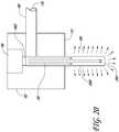
- a side view of a self-contained illuminated infusion cannula system 100 inserted through the sclera 14 of the eyeball 10, adjacent or near the pupil 12,is shown.
- the cannula system 100may operate to provide a wide-angle field of illumination to allow a surgeon to view as large of a portion of the retina and other eye features.
- the system 100can allow the surgeon to visualize the anatomical structures at the posterior portion of the eye, such as other features of the fundus, e.g. blood vessels, the optic nerve, the choroid, and the like.
- the self-contained illuminated infusion cannula system 100can generally include a body 102, an elongate member or cannula 104, a conduit 106, and a light source 108.
- the cannula system 100can further include a power source 110, an infusion port 116, and an outlet 118.
- the body or housing 102can receive infusion fluid 119 through the infusion port 116 at a distal end of the conduit 106 and light transmittance 109 from the light source 108.
- the body 102can direct fluid and permit the light to pass out the outlet 118 of the cannula 104.
- the light source 108can generate light and can be in the form of, for example, one or more of a light emitting diode (LED), an organic light emitting diode (OLED), a light bulb, or a lamp.
- LEDlight emitting diode
- OLEDorganic light emitting diode
- the light source 108 contained in the infusion cannula system 100provides certain benefits over currently available fiber optic systems, such as not being tethered to a separate light source to generate the light directed down the fiber optic.
- the light source 108allows for a self-contained system where the light source 108 can be contained within the body 102 of the system 100.
- the infusion port 116can be coupled to a fluid source 120 to provide a fluid inlet flow of infusion fluid.
- the fluid source 120can be part of, for example, a remote console, or control, system that is not shown.
- the conduit 106can extend from the infusion port 116 at one end to the body 102 at the other end.
- the cannula 104can extend from a distal end 112 of the body 102 to the outlet 118 at a distal end of the cannula 104.
- the cannula outlet 118can establish the furthest point, or location, of entry within the tissue, or eyeball as shown in Figure 1 , at a surgical site 16.
- the illuminated infusion cannula system 100can function to provide a combination of infusion fluid 119 and light 109 to the surgical site 16 during ophthalmic surgery.
- the infusion fluid 119can be provided by a remote fluid source 120 that can deliver the fluid inlet flow via a flexible tube, not shown, for example, to the infusion port 116.
- the flexible tubecan generally be biologically compatible to prevent detrimental contamination of the eye and associated tissue, e.g., silicone or the like.
- the infusion fluid 119can be a saline fluid to maintain the intraocular pressure and irrigate the surgical site.
- the infusion fluid 119can be a treatment fluid to treat the eye, or an anatomical feature of the surgical site, or an adjacent region of the anatomy.
- the infusion port 116can be coupled to the conduit 106, which in turn is coupled to the body 102.
- the body 102can include a distal end or surface 112 that can be placed adjacent the outer surface of the eye 10.
- the distal end 112can provide a support surface for the cannula system such that the cannula can be self-supported, avoiding the need for continuous handling by a surgeon or other surgical personnel for the duration of the surgical procedure.
- the distal end 112can generally rest adjacent and/or on the sclera, or the outer surface of the eye, such that the LED 108 light source is between about 0.381 mm (0.015 inches) and about 1.27mm (0.050 inches) from the outer surface of the sclera, more preferably between about 0.508mm (0.020 inches) and about 1.016mm (0.040 inches).
- the bodycan further include a proximal end or surface 114 which generally opposes the distal end 112 and, in an arrangement, can generally define the outermost proximal surface of the contiguous cannula system.
- the body 102can include several internal geometric features or characteristics that facilitate the transmittal of light 109 and the delivery of the infusion fluid 119 to the eye 10.
- the body 102can include flow passages or lumens, for example, a first lumen 202, a second lumen 204, a chamber 302, and a centerline axis 300 ( Figure 3 ).
- the body 102can further include light source related features, for example, an LED cavity 107 and a lens 304 ( Figure 3-5 ).
- the first lumen 202can define a generally circular cross-sectional passageway extending from the proximal most portion of the cannula system 100 to the distal most portion of the cannula system 100.
- the first lumen 202can extend through the body 102 and the cannula 104.
- the first lumen 202can generally be concentric with the centerline axis 300.
- the infusion fluid 119 provided via the second lumen 204flows through the first lumen 202; hence the first lumen 202 is a common lumen for delivering infusion fluid 119 and transmitting light 109 of the LED 108 through the cannula 104.
- the first lumen 202can include a cross-sectional passageway that can be any geometric shape, for example, polygonal, oval, triangular, rectangular, or the like.
- the first lumen 202can provide an additional capability, which is that of an accessway for an incision instrument, not shown, from the proximal surface 114 to the outlet 118 of the cannula 104.
- the incision instrument or trocarcan include a sharp distal tip that can facilitate cutting or puncturing the sclera 14 of the eye 10.
- the cannula 104can pass through this incision into the vitreous cavity of the eye 10.
- the first lumen 202can allow the trocar to be inserted through the cannula system 100, create the incision, and be removed from the cannula system 100 upon insertion of the cannula 104 into the eye 10.
- the insertion of an independent trocar through the first lumen 202may require access through the LED cavity 107.
- the LED 108 and any optical elementscan be removed, or moved aside, prior to trocar insertion, then installed or inserted into the cannula system 100 after the cannula 104 is inserted into the eye 10.
- the second lumen 204can define a generally circular cross-sectional passageway extending from the infusion port 116, through the conduit 106, and meeting the first lumen 202 at a junction adjacent the centerline axis 300.
- the second lumen 204can provide the passageway to deliver the infusion fluid 119 from the fluid source 120 into the first lumen 202, whereupon the fluid can provide a light transmittance medium for the light 109 emitted by the LED 108.
- the second lumen 204 and the conduit 106can be sized to receive, or couple to, the fluid source tubing, not shown.
- the fluid source tubingcan generally have an internal diameter of between about 0.762mm (0.030 inches) and about 3.175mm (0.125 inches), more preferably between about 1.27mm (0.050 inches) and about 1.778mm (0.070 inches).
- the infusion port 116can be sized to receive the tubing within the infusion port 116 internal diameter, or more preferably, to be received within the tubing internal diameter, thus having the tubing fit over the infusion port outer diameter.
- the second lumen 204 cross-sectioncan generally have a diameter of between about 0.762mm (0.030 inches) and about 3,175mm (0.125 inches), more preferably between about 1.27mm (0.050 inches) and about 1.778mm (0.070 inches), as well.
- the first lumen 202can include a cross-sectional passageway that can be any geometric shape, for example, polygonal, oval, triangular, rectangular, or the like.
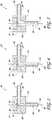
- FIG. 2-5cross-section views of several arrangements of the cannula system 100 with various arrangements of a chamber located internal to the body 102 are shown.
- the body 102can have the chamber 302 that can define the hollow volume where the first lumen 202 joins the second lumen 204.
- the chamber 302can define the region where the flow of infusion fluid 119 changes direction from that of the second lumen 204 to the direction of the first lumen 202.
- the chamber 302is a selective portion of the first lumen 202, and to a lesser degree, of the second lumen 204.
- the infusion fluid 119flows through an approximately 90 degree bend, or elbow, in the lumens of the body 102. Other degrees of bend are possible.
- the chamber 302can generally define the region of highest flow disturbances in the infusion fluid 119 as the infusion fluid 119 is delivered from the flow source tubing to the flow outlet 118 of cannula 104.
- the flow disturbances within the chamber 302 resulting from the change in flow directiongenerally results in a negligible effect on the transmittance of light 109 being emitted from the LED 108 downstream into the eye 10.
- the space between the fluid pathway and light emitting diodecan be optimized so that the cross-sectional area of the fluid conduit remains substantially constant in order to maximize and/or substantially maximize high light transmittance and/or high fluid flow rate.
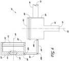
- the chambercan define the region where the lumens 202, 204 join and the infusion fluid 119 makes any required change in direction.
- the chamber 402, as shown in Figure 4can provide a converging diameter for the infusion fluid 119 and light 109 after the change in direction from the lumen 204 into the lumen 202.
- the diameter of the chamber 402can be greater than the diameter, or width, of the lens 304, or the dispersion angle of the LED 108 in the absence of a lens installed in the body 102.
- the greater diameter of the chamber 402can thus distance the LED's emitted or directed light 109 from the flow disturbances due to internal surface discontinuities and directional changes represented by the corners, or changes in surface direction, of the chamber 402.
- the change in direction of the lightcan be further influenced by features to improve the refractive index differences in the chamber and assist the light 109 passing through the first lumen 202, e.g. coatings, material selection, or the like.
- the increased distancecan reduce the effect fluid flow disturbances can impart on the light 109 transmitted downstream through the first lumen 202.
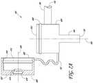
- the chambercan define the region where the lumens 202, 204 join and the infusion fluid 119 makes any required change in direction.
- the chamber 502, as shown in Figure 5can provide an increased volume for the flow disturbances imparted by the change in direction of the infusion fluid 119 flow to dampen out of the flow stream, as well as distancing the flow internal surface discontinuities from the transmitted light 109.
- the increased distance and volumecan reduce the effect fluid flow disturbances can impart on the light 109 transmitted downstream through the first lumen 202.
- the body 102can include the LED cavity 107, or aperture, extending from the proximal surface 114 into the body 102.
- the cavity 107can removably receive the LED 108, and is sized to provide a fluid seal to prevent leaking of the infusion fluid 119 during use and operation of the cannula system 100.
- the sealing functioncan be provided by any acceptable means, for example, a tightly toleranced dimensional fit between the cavity 107 and the LED 108, a biologically compatible sealing material between the cavity 107 and the LED 108, e.g. a seal, a gasket, a viscous lubricant, or the like, or other suitable means.
- the LED 108can be snapped, friction fit, or otherwise tightly located in place in the cavity 107 to prevent fluid 119 leakage.
- the LED 108can generally be located concentrically to the body 102 about a centerline axis 300, as shown in Figure 3 . In an arrangement, the LED can be offset from the centerline axis 300, as described in detail below and shown in Figure 21A .
- the LED 108can be positioned to project, or transmit, light 109 internally to the body 102 through the first lumen 202, as further shown in Figures 2-5 .
- the body 102can further include a lens 304 located along centerline axis 300 and adjacent the LED cavity 107 such that the lens can be adjacent the LED 108 and the light 109 emitted from the LED 108.
- the lens 304can be integrally molded into the body 102 during fabrication. In some arrangements, the lens 304 can be fabricated independently of the body 102 and assembled into the body 102. In some arrangements, the lens 304 can be fabricated as a part of an LED housing assembly and inserted, or installed, into the body 102 upon installation of the LED housing assembly.
- the lens 304can converge and/or collimate the light 109 emitted from the LED 108 downstream through the first lumen 202 toward and into the eye 10 and/or filter out unwanted and/or unnecessary light wavelengths from the emitted light 109 to selectively illuminate anatomical features within and/or adjacent the eye 10.
- the lens 304can further provide a sealing function within the first lumen 202 through which the incision instrument, or trocar, passes to facilitate insertion of the cannula system 100 into the eye 10.
- the lens 304 sealing functioncan be provided by any acceptable means, for example, a tightly toleranced dimensional fit between the lens 304 and the first lumen 202, a biologically compatible sealing material between the lens and the lumen 202, e.g. a seal, a gasket, a viscous lubricant, or the like, or other suitable means.
- the bodycan be fabricated integrally with the conduit 106 and the cannula 104 to define a single piece cannula system 100.
- the body 102, and the cannula system 100can be fabricated by injection molding to obtain the complex geometry and small form factor required for ophthalmic surgery and insertion into the eye 10.
- the cannula systemcan be fabricated with more than one piece and can be assembled to make the cannula system 100.
- any manufacturing methode.g. machining, adhesive bonding, or the like, can be implemented to fabricate the cannula 104 and/or the cannula system 100.
- the body 102can be made of a transparent or amber material having a high percentage of light transmission to facilitate a single piece fabrication method and provide a cannula that is transparent, capable of readily dispersing the light 109 in a wide-angle distribution pattern into the vitreous cavity of the eye 10.
- the body 102can be made of any suitable biologically compatible material such as polyamide, polycarbonate, acrylic, silicone, or the like, or a combination thereof.
- the cannula system 100can include multiple individually fabricated elements, for example the cannula 104, and/or the body 102, and/or the conduit 106, that are subsequently assembled to define the cannula system 100.
- the individually fabricated elementscan, for example, be adhesive bonded together to define the cannula system 100.
- the bodycan be fabricated of an opaque material and the cannula 104 can be fabricated from a transparent material.
- the body 102can generally have a round, or circular, periphery extending between the distal end 112 and the proximal end 114.
- the diameter of the peripherycan be between about 0.762mm (0.030 inches) and about 3.175mm (0.125 inches), more preferably between about 1.27mm (0.050 inches) and about 1.778mm (0.070 inches).
- the body 102can have a wall thickness between about 0,254mm (0.010 inches) to 0.762mm (0.030 inches).
- the height, or length, along the centerline axis 300 of the body 102can generally be between about 0.762mm (0.030 inches) and about 3.175mm (0.125 inches), more preferably between about 1.27mm (0.050 inches) and about 1.778mm (0.070 inches).
- the cannula 104can be coupled to the body 102 distal end 112.
- the cannula 104can be a hollow elongate member, or cylinder, providing a lumen to concurrently deliver the infusion fluid 119 and transmit light 109 emitted by the LED108 from the body 102 into the vitreous cavity of the eye 10.
- the cannula 104similar to the body 102, can be a transparent, or semi-transparent, or amber material having a high percentage of light transmission, cylinder to facilitate dispersion of the light 109 into the surgical site within the vitreous cavity along the full length of the cannula 104 sidewalls.
- the dispersion of the light 109, and thus the field of view at the surgical site,can be selectively controlled by geometry, transparency, and materials included in fabricating the cannula 104.
- optical elementssuch as prisms, or the like, can be fabricated into the cannula 104.
- the optical elementscan be fabricated and/or oriented to disperse at predetermined angles, and spaced longitudinally along the centerline axis 300 to obtain predetermined coverage for the field of view 1602, shown, for example, in Figure 15 .
- the cannula 104can generally include a small form factor to facilitate insertion, function, and interoperability with the possible assortment of additional instruments required at or adjacent the surgical site.
- the cannula 104can have a relatively much smaller cross-section normal to the centerline axis 300, as compared to the body 102.
- the cannula 104can include a size of between about 35 gauge and about 15 gauge, more preferably between about 30 gauge and about 20 gauge, even more preferably a size of 25 gauge or 23 gauge or 20 gauge cannula
- the cannula 104can be longitudinally sized to have a length sufficient to penetrate and extend beyond the sclera 14 of the eyeball 10 and into the vitreous cavity, yet minimize the interference with surgical site requiring visual line of sight to the surgeon and physical access to the other various instruments to perform the ophthalmic surgery.
- the cannula 104can have a length of between about 2.0 mm and about 10.0 mm, more preferably between about 2.0 mm and about 3.0 mm, and still more preferably between about 2.3 mm and about 2.7 mm.
- the cannula 104can protrude beyond the sclera a length of
- the cannula 104can provide an accessway lumen for an incision instrument, such as a trocar, for creating an incision in the sclera 14 to facilitate insertion of the cannula 104 into the eyeball 10 and the vitreous cavity.
- the cannula 104can be inserted transconjunctivally to provide for an incision that can seal suturelessly upon removal of the cannula.
- the elastic nature of the scleraforms a tight, or substantially tight, seal around the cannula to prevent vitreous fluid and/or infusion fluid or the like from leaking out of the incision.
- the distal end of the cannula 104, adjacent the outlet 118,can be formed at a non-orthogonal angle, or tapered, to the centerline axis 300 and can be provided with a tapering, or sharpened, wall thickness.
- the sharpened and angled endcan define an incision instrument capability for the cannula 104, negating the need for a separate incision instrument to extend longitudinally through the body 102 and the cannula 104 of the cannula system 100.
- Geometry, optical elements, optical coatings, and the likecan be implemented into the cannula 104, such as adjacent the outlet 118, to facilitate a symmetric and sufficient dispersion of the light 109 transmitted through the cannula system 100.
- the additional optical considerationscan offset the uneven dispersion of the light 109 out of an angled end of the cannula 104.
- the cannula 104can be made from any of a variety of transparent capable materials.
- the cannula 104can be made of any suitable biologically compatible transparent materials such as polyamide, polycarbonate, acrylic, silicone, or the like, or a combination thereof.
- the cannula 104can be integrally fabricated with the body 102 and the conduit 106 to form a single piece, or monolithic, cannula system 100.
- the cannula 104, and the cannula system 100can be fabricated by injection molding to obtain the complex geometry and small form factor.
- a single piece, or monolithic, cannula system 100 structurecan be less susceptible to breakage, providing for a more durable and/or rigid instrument.
- the cannula systemcan be fabricated with more than one piece and can be assembled to make the cannula system 100.
- any manufacturing methode.g. machining, adhesive bonding, or the like, can be implemented to fabricate the cannula 104 and/or the cannula system 100.
- the cannula system 100can further include a conduit 106, illustrated in Figures 1-5 .
- the conduit 106can provide an accessway for the infusion fluid 119 to flow from the infusion port and fluid source tubing, to the first lumen 202 and, ultimately, the eye 10.
- the conduit 106defines the portion of the second lumen 204 that is not located internally to the body 102. Therefore, the dimensional characteristics are described above with respect to the infusion port and the second lumen 204.
- the length of the conduitcan vary according to the particular application of the cannula system 100.
- the cannula system 100can include the LED 108 that can be coupled to the body 102 within the LED cavity 107.
- the LED 108advantageously provides an efficient high intensity light source requiring low power consumption with decreased light 109 transmission loss in transmitting light 109 from the LED 108 to the surgical site within the vitreous cavity of the eye 10. Additionally, the LED 108 provides a reliable, low cost light source to the cannula system 100, such that the cannula system 100 can be a disposable surgical instrument.
- the light sourcecan be an organic light emitting diode (OLED).
- LED light sources used in/for arrangements of the present disclosurecan provide various advantages. As they are based on electronic component design, LEDs are largely, if not entirely, immune from or resistant to system vibrations. LEDs can be protected from dirt and moisture, facilitating useful lifetimes that can increase to, or approach, thousands of hours, which is much higher than a non-LED light source. Further, LED-based light sources can operate at lower temperatures, and therefore have lower heat dissipation requirement, thereby eliminating complex heat sink systems commonly used for lighting techniques. Cost of a single LED system is exponentially less expensive than a standard light source system because of the simpler packaging. Additionally, LEDs are available in multiple colors/including high output efficiency.
- LEDsare devices that convert electrical energy into optical energy.
- An LEDis a semiconductor based diode, or device, including a p-doped region and a n-doped region.
- the principle behind an LEDprovides that as an electron in the conduction band recombines with a hole in the valence band, the electron makes a transition to a lower-lying energy state. This leads to the release of energy in an amount equal to the band-gap energy.
- the energyis dissipated by phonons, i.e. heat, or photons, i.e. light. In an LED, this energy is directed into emitted light energy.
- LEDWhen an LED is stimulated electrically by a pulsed current or by a current produced in response to an applied voltage, electrons and hole carriers in the p-n junction recombine, emitting photons as an incoherent narrow spectrum of light.
- This phenomenonis termed electroluminescence, where the color, e.g. UV, Visible, or IR, of light depends on the type of the semiconductor materials used for the p-doped region and n-doped region.
- the optical power the LED emitscan be dependent on the doping and/or the forward current through the diode interface.
- the frequency response of LED'sare approximately 120 Hz and the light can be collimated with a lens system. Further details are provided in Application Serial No. 12/237,110 filed September 24, 2008 , which is published as US2009146583 A1 .
- the LED 108can be assembled, or potted, into a tray, or housing, that can readily assemble into the cannula system 100, in particular the LED cavity 107.
- the housingsimilar to the body 102, cannula 104, and conduit 106, can be fabricated from any suitable biologically compatible transparent material, e.g. polyamide, polycarbonate, acrylic, silicone, or the like, or a combination thereof. In an arrangement, the housing material can be opaque except for the window area located adjacent the LED 108 light exit.
- the LED 108can be encapsulated, or housed, in a transparent or semi-transparent housing and can be inserted or installed into various cannula and/or body 102 configurations configured to receive the housing, or tray, in any variety of orientations of the LED or cannula and/or positions within the cannula, either alone or in combination with filters, lenses, or any combination or quantity of each thereof.
- the LED 108 parameterscan provide intensity to the eye 10 of between about 4 lumens and about 25 lumens, more preferably between about 7 lumens and about 20 lumens.
- the wavelength of light transmitted to the eye 10, after being emitted from the LED and subsequently transmitted and conditioned through a window, filter, lens, or combination thereof,can be between about 400 nm and about 700 nm, more preferably between about 430 nm and about 660 nm.
- the beam sizecan be between about 0.2 mm and about 3.0 mm, more preferably between about 0.3 mm, and about 1.4 mm, and more preferably between about 0.4 mm and about 1.0 mm. In an arrangement, the beam size is defined adjacent an optical element, such as lens 304, or the like.
- the direct transmission of the LED 108 light source into the vitreous cavity of the eye 10 via the first lumen 202 and the transparent cannula 104can advantageously minimize light transmission loss and can improve light intensity because of the adjacent positioning of the light source to the eye as compared to currently available fiber optic light systems.
- the use of a direct transmission LED eliminating a fiber optic linecan also reduce the torque applied to the cannula system 100 by the appurtenant instruments, and can enable hands-free surgical illumination.
- the self contained illuminated infusion cannula system 100can reduce the number of incisions required, thereby allowing bimanual, or two ports, surgery.
- the cannula system 100can illuminate the eye with various colors and/or tints with and without combinational instruments.
- a fiber optic light sourcecan be provided to augment the LED 108.
- both a fiber optic light source and an LEDmay increase torque on the cannula system 100 which can be acceptable under certain conditions.
- the LED housingcan be utilized to house an ultrasonic transducer, rather than an LED light source.
- the ultrasonic transducercan be implemented for treatment of the eye 10.
- the transducercan be a high intensity focused ultrasound (HIFU) that can direct concentrated heat and/or vibration at tissue within the eye, or the transducer can be a high power focused ultrasound (HPFU) to transmit vibration across a larger area to emulsify tissue within the eye.
- HIFUhigh intensity focused ultrasound
- HPFUhigh power focused ultrasound
- the use of an ultrasonic transducercan be combined with any of the cannula system arrangements disclosed herein.
- the power source 110can comprise a separate power supply box from which electrical lines can be coupled to the LED 108 light source ( Figure 1 ).
- the electrical linescan be thin, lightweight insulated wires that can apply minimal and/or substantially minimal torque on a cannula system 100 inserted and resting on, or adjacent, the sclera 14 of the eye 10.
- the power source 110 energy supply componentcan be an AC source or a DC source (for example, a battery or rectified AC source) and can also power an electronic control panel system, not shown.
- the electronic systemin turn, can consist of the microprocessor circuitry, described in detail below, which can be operational to provide a signal, for example a current pulse, to the one or more LED 108 light sources.
- the circuitrycan include a converter/regulator, or a boost converter.
- a convertercan be operable to step up the battery voltage to that required for LED light sources.
- a cannula system 100 with a removable cap 600is shown.
- the cannula system 100can include a body 624 similar in configuration to the body 102 described in detail above, with the exception of additional features to interface with the cap 600.
- the removable cap 600provides an additional means of moving the LED 616 out of or away from the accessway for the incision instrument and then coupling the LED 616 adjacent the first lumen 202 in a manner that prevents fluid 119 leakage past the LED 616 or the LED tray or housing.
- the body 624can include a proximal end 612 and a protrusion 608 adjacent the proximal end 612.
- the protrusion 608can be located substantially around the periphery of the body 624 to ensure a tight equally distributed load between the cap 600 and the body 624 when the cap 600 is located or snapped over the protrusion 608.
- the protrusion 608can include a plurality of independent protrusions spaced circumferentially about the periphery of the body 624.
- the cap 600can include a distal end 620 and a proximal end 622, as determined when the cap 600 is attached to the body 624.
- the cap 600can further include a recess 610, a lens 614, an LED 616, and a lip 618.
- the LED 616is located in a central portion of the proximal end 622, substantially aligned with a cap centerline axis 626.
- the lens 614can be coupled to the cap adjacent the LED 616, also substantially aligned with a cap centerline axis 626.
- the lip 618can be configured to be placed around the body 624 protrusion 608, such that the cap 600 receives the body 624.
- the cap 600 and the body 624can be coupled together, the axis 626 can be substantially coaxial with the body centerline axis 300 when the cap 600 and the body 624 are coupled.
- the recess 610extends substantially around an internal cavity of the cap 600, the recess being shaped to receive and interface with the protrusion 608.
- the fit, or dimensional tolerancing, between the cap 600 and the body 624is sufficiently tight that when the cap 600 is coupled to the body 624, a sufficient load is distributed across the interfacing surfaces to prevent fluid 119 leakage.
- the cap 600is configured to be received into the proximal end 612 of the body 624 to couple the body 624 and the cap 600 together.
- the cap 600can be hinged or coupled to the body 624 via at least a pair of arms 602, 604 that can be hingedly coupled to each other.
- the opposing ends of the arms 602, 604can be hingedly coupled to the cap 600 and the body 624, respectively.
- the arms 602, 604, cap 600, and body 624are coupled via hinges 606a-c, which can provide relative rotation between the hinged elements about the hinge. Other hinging configurations or arrangements, are possible.
- the hinged couplingadvantageously provides the convenience of containing the cap 600 adjacent the surgical site when the cap 600 is removed from the body 624 to insert the incision instrument, or trocar.
- the cap 600Upon completing the incision, inserting the cannula 104 into the eye 10, and removing the trocar, the cap 600 can be rotated about the hinged arms and lockingly engaged onto the body 624.
- the arms 602, 604can be removed, including destructively removed, from the cap 600 and body 624 to create an open work area about the surgical site and avoid inadvertent contact with the flexible hinge.
- the cannula system 100 with a flexible arm 702 coupling the cap 600 and the body 624is shown.
- the flexible arm 702can provide an alternative hinging mechanism between the cap 600 and the body 624.
- the flexible arm 702can allow a single piece molding of the cap 600 and the body 624, whereby only the LED 616 is required to be potted into the cap 600 to define a complete cannula system 100.
- the cap 600 and body 624 and independent piecesthat are, for example, adhesively bonded to each other via the flexible arm 702.
- the flexible arm 702can be removed from the cap 600 and body 624 to create an open work area about the surgical site and avoid inadvertent contact with the flexible hinge.
- the cannula system 100 with another arrangement of the cap 600 and the body 624is shown.
- the cap 600can include a cap extension 708 in the cap cavity that protrudes downward from the cap proximal end 622 toward the distal end 620.
- the body 624can include first lumen 706 and the chamber 704.
- the cap extension 708can locate the LED 616, and lens 614, if applicable, closer to the junction between the first lumen 706 and the second lumen 204.
- the chamber 704can be shaped to receive the cap extension 708. Placement of the LED 616 closer to the cannula outlet 118 can reduce light losses and improve the light transmittance to the eye 10.
- the cap 600 having cap extension 708can be coupled to the body 624 by flexible arm 702, hinged arms 602, 604, or a functionally equivalent hinging mechanism, device, or method.
- the cannula system 100is shown with a cap 800 and a body 824.
- the cap 800can include a proximal end 822, a distal end 820, and a cone 826.
- the body 824can include a proximal end 812 and a chamber 828.
- the cap 800is similar to cap 600 except the cap 800 can include the cone 826 that extends downward away from the cap proximal end 822 and protrudes beyond the location where the fluid 119 enters the chamber 828 from conduit 106.
- the cone 826can advantageously position the LED 616, and the lens 614 if applicable, below the 90 degree bend from the second lumen 204 to the chamber 828 and the first lumen 706, as illustrated in Figure 8 . Positioning the LED 616 below the second lumen 204 can place the LED downstream of the flow disturbances generated by the bend (for example, the 90 degree bend), and can reduce the likelihood of the flow causing loss of light 109 transmittance and/or shadows in the light.
- the chamber 828can include almost the entire internal volume of the body 824.
- the chamber 828can include any geometry similar to, or equivalent to, the chamber geometries described above, provided the cone 826 is compatible and can interface the various geometries when the cap 800 is lockingly engaged with the body 824.
- FIG. 9-13an arrangement of a cannula system 900 is shown.
- the cannula system 900can provide for a second aperture 910 positioned on the periphery of a body 902 that allows lateral movement of the LED 918 away from a centerline axis 1000.
- the lateral movement of the LED 918can establish access through a first lumen 1024 for the incision instrument, or trocar.
- the LED 918can then be urged laterally to lockingly engage and establish a fluid seal with the body 902.
- the body 902can include a distal end 908 and a proximal end 906.
- a first aperture 904can be positioned adjacent the proximal surface at the proximal end 906.
- the first aperture 904can open to a first lumen 1024 that extends the full length of the body 902 and the cannula 104.
- the second aperture 910can define an opening into the body 902, the opening defining a chamber 912.
- the chamber 912can be configured to receive an insert or LED tray/housing 916.
- the chamber 912can include a tapered surface 1002 on a proximal surface of the chamber 912.
- the tapered surface 1002can define a decreasing thickness, or longitudinal height, of the chamber 912 as the second aperture 910 extends further away from the opening of the second aperture 910.
- the decreasing height of the chamber 912can define a wedge-like feature that lockingly receives a similarly shaped end of the insert or LED tray/housing 916.
- the wedge shapecan force the insert 916 distally, creating downward forces, and can create a fluid seal between a bottom face 924 of the insert 916 and a distal surface of the chamber 912.
- the sealing functioncan be provided by any acceptable means, for example, a tightly toleranced dimensional fit between the insert 916 and the chamber 912, a biologically compatible sealing material between the insert 916 and the chamber 912, e.g. a seal, a gasket, a viscous lubricant, or the like, or other suitable means.
- the insert 916can include the bottom face 924, a front face 922, an LED 918 in a cavity, and a top tapered surface 920.
- a lens 1004can be coupled to or adjacent the bottom face 924.
- the tapered surface 920can include a taper angle ⁇ , that can be between about 0.25 degrees and about 10 degrees, more preferably between about 0.75 degrees and about 3 degrees.
- the top tapered surface 920can taper across any lateral length, which can correspondingly vary the wedge contact surface and the downward distally directed fluid sealing force distribution.
- the body 902 and the insert 916can be coupled by a pair of connector members 914.
- the connector memberscan provide for a single piece integrally molded assembly of the cannula system 900.
- the connector members 914can be decoupled at the insert 916.
- the surgeoncan use instruments, such as a pair of forceps, to urge the insert 916 into the aperture 910 and chamber 912.
- the connector members 914can provide an additional locking mechanism, in addition to the tapered wedge locking feature, to retain the insert 916 in the chamber 912.
- the locking mechanism of connector members 914can also prevent removal of the insert 916 such that the cannula system 900 can only be a single use medical device system.
- FIG. 14-17arrangements of a cannula system 100 having varying optical elements coupled to the cannula, are shown.
- the dispersion of the light 109, and thus the field of view at the surgical sitecan be selectively controlled by the geometry, transparency, and materials included in fabricating a cannula 104.
- Optical elements 1406a-dcan be fabricated into the cannula 104.
- the optical elements 1406a-dcan be devices such as prisms, lenses, filters, or the like.
- the optical elements 1406a-d, as illustrated in Figures 14 and 15can extend circumferentially for at least a portion of the cannula 104 outer diameter.
- the optical elementscan be fabricated and/or oriented to disperse at predetermined angles 1408a-d, and spaced longitudinally along a centerline axis of the cannula 104 to obtain predetermined coverage for the field of view 1602, shown, for example, in Figure 15 .
- the predetermined angles 1408a-dcan be the same or substantially the same, all different or substantially different, or any combination thereof, to define the field of view 1602.
- a cannula 104 having optical element 1502 located at the cannula outlet 118is shown.
- the cannula 104can have a single optical element, for example a prism can extend circumferentially around the full outer diameter of the cannula 104.
- the dispersion beam anglecan define the beam area and ultimately the field of view 1702.
- Comparison of field of views 1602, 1702can indicate the variation in illumination capability, including depth and width, dependent upon the optical element parameters, characteristics, and quantity.
- Cannula 1402can include prisms having a greater dispersion angle relative to the cannula outer diameter and can include a greater number of prisms coupled to the cannula.
- the resulting field of view 1602can be significantly larger than the field of view 1702, which can have a smaller dispersion angle 1504 and only a single prism 1502 located at the distal end of the cannula 104.
- the cannula 1802is similar to the cannula arrangements described above except the cannula 1802 can include a plurality of fluid apertures 1804a-e.
- the fluid apertures 1804can be spaced longitudinally and circumferentially, and can provide apertures at various depths in the eye 10 and at various angles relative to a longitudinal axis.
- the fluid apertures 1804can provide exit outlets for the infusion fluid 119 to irrigate and provide intraocular pressure to the eye 10.
- the fluid apertures 1804can evenly distribute the infusion fluid 119 and avoid delivery of the fluid 119 to only a local portion of the vitreous cavity of the eye 10.
- the fluid apertures 1804can transmit light 109 at predetermined angles and longitudinal locations.
- the cannula 1900can include at least a portion of the distal tip 1904 that can include a phosphorescence material applied or coupled to the surface and/or embedded in the transparent material.
- the cannula system 100can further include an optical element 1902 that can selectively disperse wavelengths of light 109, and the wavelengths associated energy.
- the optical elementcan further collimate the selectively disperse wavelengths to facilitated transmittance through the full length of the cannula 1900.
- the selective wavelengthstransmit through, and the wavelength energy excites, the phosphorescence material located on the cannula 1900.
- the tipgenerates divergent relaxation wavelength lights and illuminates the surgical sight. The illuminated light can result in an intraocular illumination with relatively high intensity.
- the light source systemcan be a light emitting diode system that can generate white light, or so-called warm white light.
- the light emitting diode systemcan comprise a light emitting diode, generating blue light, wherein the tip and/or wall of the optical bus is coated with a phosphorous layer.
- this layerin turn generates a greenish and yellowish light accompanied with the original bluish light, and the light generated by the light emitting diode system can be whitish depending on the contribution of the blue, green, and yellow lights.
- the light source systemcan be a laser diode system that can generate white light.
- the laser diode systemcan comprise a laser diode, generating blue light, wherein the tip and/or wall of the optical bus is coated with a phosphorous layer.
- this layercan generate a greenish and/or yellowish light accompanied with the original bluish light, and the light generated by the laser diode system can be whitish depending on the contribution of the blue, green, and/or yellow lights.
- bandwidth limited wavelength lightallows physicians to operate with improved contrast for visualization of specific structures in the eye. Additional features include controlling not only the intensity, but also the quality of the light, which is improved by changing the color, or color temperature, of the light from the light source via a filter device, with the light produced from one or more sources. Further details regarding these bandwidth limited light and light coloration modifying devices, systems, and methods for providing illumination are shown and described in U.S. Patent No. 7,654,716 and in U.S. Publication 2009-0146583 .
- a cannula system 100 with a cannula 2000is shown.
- the cannula systemis similar to the system illustrated in Figure 19 , except the cannula 2000 can include a phosphorescence material applied or coupled to the surface and/or embedded in the transparent material along the full length of the cannula 2000 from the distal end 112 of body 102 to the distal end 2004 of the cannula 2000.
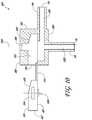
- a cannula system 2100is shown with an LED 2104 offset to the side of the first lumen 202.
- the majority of the cannula system 2100is similar to the cannula systems described above, except for the location of the LED 2104, the location and configuration of an optical element 2108, and the length of the first lumen 202.
- the LED 2104can extend lengthwise, parallel to the first lumen 202.
- the position of the LED 2104 off to the side of the body 102can negate the need to move the LED 2104 out of the first lumen 202 to provide a passage for the incision instrument or trocar.
- the arrangement illustrated in Figures 21A and 21Bcan simplify creation of the incision.
- the LED position adjacent the first lumen 202can direct the light transmitted from the LED across laterally through the first lumen 202 rather than distally toward the eye 10.
- the optical element 2108can redirect, filter, magnify, or the like, the light 109 from the lateral direction to be directed distally through the first lumen 202 toward the eye 10.
- the optical element 2108can be springingly coupled to a window 2118 defined by a thin transparent portion of the body 102 that can be positioned between the LED 2104 and the first lumen 202.
- the resilient spring-like, spring-loaded characteristic of the optical element 2108can provide for temporary displacement of the optical element 2108 adjacent the sidewall of the first lumen 202 while the trocar is inserted through the first lumen 202.
- the optical element 2108, the first lumen 202, and the trocarcan be sized such that the optical element and the trocar can movingly fit relative each other within the first lumen 202.
- the LED 2104 position illustrated in Figure 21Bcan be advantageously located in the optical element 2108 downstream of the 90 degree bend through which the fluid 119 passes in transitioning from the second lumen 204 to the first lumen 202.
- the downstream positionplaces the optical element 2108 substantially beyond the greatest flow disturbances generated by the flow around the 90 degree bend between the two lumens.
- a cannula system 2100is shown with at least two LEDs 2104 offset to the side of the first lumen 202.
- the cannula system of figure 21Cis similar to the cannula system of Figure 21A and 21B except that there is more than one LED positioned in the body 102.
- the arrangement to redirect the lateral transmittance of the LEDsis also similar. Having more than one LED can allow each LED to be positioned slightly offset in the longitudinal direction from the first lumen 202. This can provide dimensional clearance for the one or more optical elements to project light into the first lumen 202.
- the plurality of LEDscan have the individual light 109 transmittance directed to a single optical element that will redirect the combined light 109 from the LEDs through the first lumen 202 toward the eye 10.
- the position of the LEDs 2104 to the sides of the body 102can also negate the need to move the LED(s) 2104 out of the first lumen 202 to provide a passage for the incision instrument or trocar 2114.
- the multiple LEDs 2104can include LEDs of various colors, such as blue, red, yellow, and white.
- the multiple LEDs 2104 of different colorscan be provided on separate individual dies, or can include different color LEDs on a single die.
- These LED light sourcescan provide an optical signal/output for illumination in a band of specific wavelengths.
- the different sources, red, green, blue, white, etc.can be configured in a designated pattern for maximum light output efficiency.
- One of the advantages of using this configurationis that by controlling the current to the LED, the output light can be tuned to various intensities. This can allow for better safety, visualization, and illumination that is tunable to individual cases and surgeons.
- the variation in light of different spectrum from the outputs of the LEDs 2104can allow for improved contrast ratios for surgical illumination.
- an illumination systemcan use multiple LED 2104 sources to provide increased flux strength for illumination.
- the multiple LEDs 2104can be arranged in desired configurations about the first lumen 202, such as equally spaced circumferentially, hex, line, chandelier, or the like.
- the entire visible spectrum of the LED 2104 light source wavelength optical outputis usable. Additionally, the optical intensities of the LEDs 2104 are easily tunable with the input current.
- Light produced by the LEDscan be dispersed through the lens 2108.
- the lens 2108can be made using any suitable materials and/or shapes. Further, any suitable confguration, e.g., thin film, Fabry-Perot, or the like, and/or material can be used for a filter applied to the light 109 dispersed from the LED 2104.
- One or more lensescan provide optional magnification, collimation, or focusing within the first lumen 202. Further details are provided in Application Serial No. 12/237,110, filed September 24, 2008 , which is published as US2009146583 A1 .
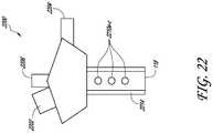
- the cannula system 2200includes two fluid infusion ports 2204, 2206, and offset externally positioned LED 2202 light source, a phosphorescence coated or embedded material cannula 2214, and fluid apertures 2210a-c.
- the cannula system 2200provides an additional arrangement that can selectively disperse the LED 2202 light wavelengths such that the desired energy is transmitted to the phosphorescence coated or embedded cannula 2214 to excite the material and advantageously illuminate surgical site in or adjacent to the eye 10.
- the fluid apertures 2210a-ccan provide infusion flow outlets to evenly deliver the infusion fluid 119 about the surgical site.
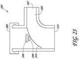
- a cannula system 2300is shown.
- the cannula system 2300is similar to the cannula systems described above except that the 90 degree bend can be provided with a generous transition radius rather than a sharp 90 degree bend transition.
- the generous transition radiuscan advantageously reduce the flow disturbances that are adjacent to a LED 2304 and a lens 2306, if the optional lens is implemented in the arrangement.
- At least a portion of the flow bend transition radius 2310can be fabricated as part of a modular cap 2302, similar to the caps described above. Fabricating the radiused surface on an external surface of a separate piece of the cannula system can simplify the fabrication of the body.
- the transition radius illustrated in Figures 23 and 24shows the inner diameter of the second lumens 2320 having a larger magnitude than the inner diameter of the first lumen 2312.
- a cannula system 2500is shown.
- the cannula system 2500is similar to the cannula system 2300 shown in Figures 23 and 24 except the inner diameter of the second lumen 2520 can have a smaller magnitude than the inner diameter of the first lumen 2512.
- a cannula system 2600is shown.
- the cannula system 2600is similar to the cannula systems described above except for the following features.
- the cannula systemcan include a body 2602, a cannula 104, and a chamber 2616, and an opening 2608.
- the cannula systemcan comprise a LED tray 2606 that is configured to slide laterally to allow instruments to pass through the cannula 104.
- the LED tray 2606can be configured to move from a first closed position to a second opened position.
- the cannula 104can define at least a portion of a first lumen 202 that can receive a trocar 2612, as illustrated in Figure 26 .
- the cannula systemis prepackaged with a trocar positioned within the lumen 202 such that the LED tray 2606 is in the second opened position. After the trocar is used to make an incision in the eye, the trocar can be removed from the cannula 104, thereby allowing the LED tray 2606 to move laterally into the first closed position.
- the cannula 104is not prepackaged with a trocar positioned within the cannula.
- a trocarcan be inserted into the cannula 104.
- the distal end of the trocarcan be configured to engage a tapered surface of the LED tray 2606 to urge the LED tray 2606 laterally to open the cannula 104 thereby allowing the trocar to pass through.
- the chamber 2616can have a tapered proximal surface to define a wedge like feature as described above in detail in reference to Figures 9-13 .
- the cannula system 2600can further include the LED tray 2606, an LED 2614, and a resilient member, or spring 2610.
- any suitable resilient materialcan be included in the cannula system 2600.
- the springcan be positioned to a lateral side adjacent the opening 2608.
- the opening 2608can provide access to the LED tray 2606 and the spring 2610.
- the access through the opening 2608can provide for the LED 2614 to be potted into the LED tray 2606.
- the chamber 2616can receive the LED tray 2606, whereupon the LED tray 2606 can be urged to a lateral side against the resistance of spring 2610 and away from the first lumen 202 to allow the trocar 2612 to pass through the first lumen 202.
- the LED tray 2606can include a tapered top, or proximal, surface to define a corresponding wedge shaped feature for sliding interaction with the tapered surface of the chamber 2616. Removal of the trocar 2612 upon insertion of the cannula 104 into the sclera 14 provides for the spring to urge the LED tray 2606 adjacent the tapered surface of the chamber 2616. The LED tray 2606 is urged such that the LED 2614 is substantially aligned to transmit light 109 distally through the first lumen 202 into the vitreous cavity of the eye 10. In an embodiment, the LED tray 2606 forms a seal with the side walls of the lumen 202.
- the tapered surfaces of the LED tray 2606 and the chamber 2616can be configured to provide counter forces that help ensure a tight seal.
- the LED tray 2606is positioned above the second lumen 204, thereby allowing the force of the entering infusion fluid to further push or urge the LED tray 2606 upward or proximally to form a tighter seal to prevent fluid from exiting the body 2602.
- the LED tray 2606can pivot about an end of the tray, rather than laterally slidable as described above.
- the traycan pivot about an end that is coupled to a portion of the chamber 2616.
- the free end, or any portion of the LED tray 2606can be resiliently coupled to a portion of the chamber 2616. Accordingly, the LED tray 2606 can pivot into and out of the first lumen 202 with resilient resistance provided by a suitable resilient member or spring 2610.
- a trocarcan be inserted and removed, urging aside and releasably positioning the LED tray 2606 adjacent the first lumen 202 in the process.
- the LED tray 2606can be configured to pivot in any suitable direction that can place the LED tray adjacent the first lumen 202 for directing the light 109 out through cannula 104, e.g., laterally, axially, or the like. Accordingly, the LED tray can be configured to move from a normal, at rest, first position to a second position as the trocar is inserted into the first lumen 202, thereby allowing the trocar to pass through the lumen 202. When in the first position, the LED tray 2606 can be urged into a lateral position or a position that is perpendicular to the longitudinal axis of the lumen 202. In an embodiment, the LED tray 2606 forms a seal with the side walls of the lumen 202.
- the side walls of the lumen 202can have a lip to interface with the LED tray 2606.
- the LED tray 2606is positioned above the second lumen 204, thereby allowing the force of the entering infusion fluid to further push or urge the LED tray 2606 upward or proximally to form a tighter seal to prevent fluid from exiting the body 2602.
- the cannula system 2600can include assembling the LED 2614 into the LED tray 2606.
- the LED 2614can be coupled to the tray 2606 by potting the LED into an LED cavity within the tray, and locating the LED adjacent a transparent window for transmitting light 109 through the first lumen 202.
- Assembling the cannula 2604can include placing a trocar 2612 and extending it through, and out, the distal end of the cannula 104. The inserting of the trocar through the cannula 104 and thus, the first lumen 202, advantageously urges the LED tray 2606, laterally moving the tray 2606 in the direction toward and against the resilience of the spring 2610.
- the sharpened tip of the trocar 2612can be aligned with the desired incision, or insertion, location on the sclera 14 of the eye 10 that is suitable to illuminate the surgical site within the vitreous cavity. Locating the cannula 104 and the trocar 2612 adjacent and substantially normal, or any suitable angle of entry for the trocar 2612, the cannula 104 and body 2602 is statically positioned. Urging the trocar 2612 through the statically positioned body 2602 and cannula 104, the sharpened distal tip of the trocar 2612 penetrates the sclera, creating a suitable passage for the cannula 104.
- the trocarcan then be held statically positioned in the course of urging the body 2602 toward the outer surface of the sclera and concurrently urging the cannula 104 through the incision created by the trocar 2612.
- the cannula 104slides distally about the statically positioned trocar 2612.
- the elastic nature of the sclera 14forms a sealing engagement about the cannula 104 to prevent leakage of vitreous fluid, infusion fluid, or the like.
- the trocar 2612can be removed from the cannula system 2600 by proximally urging and sliding the trocar outward away from the eye 10 and out of the first lumen 202. Removing the trocar 2612 allows the LED tray 2606 to releasably and slidably enter the chamber 2616.
- the resiliency of the spring 2610is configured to laterally move or suitably position the LED light transmittance portion over, or adjacent, the first lumen 202.
- Urging of the LED tray 2606 into the wedge receiving geometry of the chamber 2616generates fluid sealing downward forces between the LED tray 2606 and the distal surfaces of the chamber 2616.
- the opening 2608provides access to supply additional locating loads against the LED tray 2606 to assist the spring 2610 and facilitate suitable location of the LED 2614 about the first lumen 202.
- the cannula 104can be adjusted by positioning the cannula system into a suitable arrangement and orientation adjacent the outer surface of the sclera 14 as well as in the vitreous cavity of the eye 10.
- Providing power to the LEDtransmits light 109 out of the LED 2614 and the LED tray 2606.
- the light 109is transmitted, or permitted to pass, distally through the first lumen 202 into the vitreous cavity of the eye 10.
- Modifying the power source provided to the LED 2614can vary the light transmittance to the surgical site according to a suitable illumination within the vitreous cavity and adjacent the eye 10.
- FIG. 27is a cannula system 2700, similar to other arrangements described above, except that a length of fiber optic 2702 is coupled to a lens 2704. Fiber optic 2702, depending on the light illumination criteria, may extend partially or fully through lumen 2706 of cannula 2708. Because light source 2710 (preferably an LED, as shown) is contained in body 2712 adjacent lens 2704 more light may be transmitted to a surgical site compared to prior art arrangements having a remote light source transmitting light through a fiber optic length much longer than fiber optic 2702.
- the relatively short length of fiber optic 2702(preferably less than 2 cm) causes less light loss compared to prior art fiber optic arrangements with fiber lengths of hundreds of centimeters. The lower light loss allows the use of a lower power consuming and lower light producing light source 2710 to produce an acceptable illumination level, compared to prior art arrangements.
- Body 2712also includes an infusion port 2714 for receiving fluid to be delivered to a surgical site through lumen 2706. Also, shown is a power source 2716 contained within the body 2712 for powering light source 2710. It is also possible with advances in LED technology that light source 2710 may be placed at distal end 2718 of cannula 2708 and still allow infusion fluid to flow to a surgical site through lumen 2706. If light source 2710 is placed at distal end 2718, an electrical connection may extend through lumen 2706, instead of fiber optic 2702, and connect to power source 2716 or to a remote power source connection (not shown).
- the systems, processes, and methods described aboveare implemented using a computing system, such as the one shown in Figure 28 .
- the computer system 2802is in communication with one or more computing systems 2820 and/or one or more data sources 2822 via one or more networks 2818. While Figure 28 illustrates an arrangement of a computing system 2802, it is recognized that the functionality provided for in the components and modules of computer system 2802 may be combined into fewer components and modules, or further separated into additional components and modules.
- the computer system 2802includes an illumination and infusion control module 2814 that carries out the functions, methods, acts, and/or processes described herein.
- the illumination and infusion control module 2814is executed on the computer system 2802 by a central processing unit 2810 discussed further below.
- modulerefers to logic embodied in hardware or firmware or to a collection of software instructions, having entry and exit points. Modules are written in a program language, such as JAVA, C or C++, or the like. Software modules may be compiled or linked into an executable program, installed in a dynamic link library, or may be written in an interpreted language such as BASIC letters, PERL, LUA, or Python. Software modules may be called from other modules or from themselves, and/or may be invoked in response to detected events or interruptions. Modules implemented in hardware include connected logic units such as gates and flip-flops, and/or may include programmable units, such as programmable gate arrays or processors.
- the modules described hereinrefer to logical modules that may be combined with other modules or divided into sub-modules despite their physical organization or storage.
- the modulesare executed by one or more computing systems, and maybe stored on or within any suitable computer readable medium, or implemented in-whole or in-part within special designed hardware or firmware. Not all calculations, analysis, and/or optimization require the use of computer systems, though any of the above-described methods, calculations, processes, or analyses maybe facilitated through the use of computers. Further, in some arrangements, process blocks described herein may be altered, rearranged, combined, and/or omitted.
- the computer system 2802includes one or more processing units (CPU) 2810, which may include a microprocessor.
- the computer system 2802further includes a memory 2812, such as random access memory (RAM) for temporary storage of information, a read only memory (ROM) for permanent storage of information, and a mass storage device 2804, such as a hard drive, diskette, or optical media storage device.
- RAMrandom access memory
- ROMread only memory
- mass storage device 2804such as a hard drive, diskette, or optical media storage device.
- the mass storage devicemay be implemented in an array of servers.
- the components of the computer system 2802are connected to the computer using a standards based bus system.
- the bus systemcan be implemented using various protocols, such as Peripheral Component Interconnect (PCI), Micro Channel, SCSI, Industrial Standard Architecture (ISA) and Extended ISA (EISA) architectures.
- PCIPeripheral Component Interconnect
- ISAIndustrial Standard Architecture
- EISAExtended ISA
- the computer system 2802includes one or more input/output (I/O) devices and interfaces 2808, such as a keyboard, mouse, touch pad, and printer.
- the I/O devices and interfaces 2808can include one or more display devices, such as a monitor, that allows the visual presentation of data to a user. More particularly, a display device provides for the presentation of GUIs as application Software data, and multi-media presentations, for example.
- the I/O devices and interfaces 2808can also provide a communications interface to various external devices.
- the computer system 2802may include one or more multi-media devices 2806, such as speakers, video cards, graphics accelerators, and microphones, for example.
- the computer system 2802may run on a variety of computing devices, such as a server, a Windows server, and Structure Query Language server, a Unix Server, a personal computer, a laptop computer, and so forth. In other arrangements, the computer system 2802 may run on a mainframe computer suitable for controlling and/or communicating with large databases, performing high volume transaction processing, and generating reports from large databases.
- the computing system 2802is generally controlled and coordinated by an operating system software, such as z/OS, Windows 95, Windows 98, Windows NT, Windows 2000, Windows XP, Windows Vista, Windows 7, Lenox, BSD, SunOS, Solaris, or other compatible operating systems, including proprietary operating systems. Operating systems control and schedule computer processes for execution, perform memory management, provide file system, networking, and I/O services, and provide a user interface, such as a graphical user interface (GUI), among other things.
- GUIgraphical user interface
- the computer system 2802 illustrated in Figure 28is coupled to a network 2818, such as a LAN, WAN, or the Internet via a communication link 2816 (wired, wireless, or a combination thereof).
- Network 2818communicates with various computing devices and/or other electronic devices.
- Network 2818is communicating with one or more computing systems 2820 and one or more data sources 2822.
- the illumination and infusion control module 2814may access or may be accessed by computing systems 2820 and/or data sources 2822 through a web-enabled user access point. Connections may be a direct physical connection, a virtual connection, and other connection type.
- the web-enabled user access pointmay include a browser module that uses text, graphics, audio, video, and other media to present data and to allow interaction with data via the network 2818.
- the browser module or other output modulemay be implemented as a combination of an all-points addressable display such as a cathode ray tube (CRT), a liquid crystal display (LCD), a plasma display, or other types and/or combinations of displays.
- the output modulemay be implemented to communicate with input devices 2808 and they also include software with the appropriate interfaces which allow a user to access data through the use of stylized screen elements, such as menus, windows, dialogue boxes, tool bars, and controls (e.g., radio buttons, check boxes, sliding scales, and so forth).
- the output modulemay communicate with a set of input and output devices to receive signals from the user.
- the computing system 2802may include one or more internal and/or external data sources (e.g., data sources 2822).
- data sources 2822e.g., data sources 2822
- one or more of the data repositories and the data sources described abovemay be implemented using a relational database, such as DB2, Sybase, Oracle, CodeBase, and Microsoft® SQL Server as well as other types of databases such as a flat-file database, an entity relationship database, and object-oriented database, and/or a record-based database.
- the computer system 2802 as shown in Figure 28accesses one or more attribute filters.
- the attribute filtersmay be stored in a database or data repository.
- the computer system 2802may access the one or more attribute filters through a network 2818 or may directly access the database or data repository through I/O devices and interfaces 2808.
- the data repository storing the one or more attribute filtersmay reside within the computer system 2802.
- the computer system 2802also accesses one or more consumer verification databases.
- the consumer verification databasesmay be stored in a database or data repository.
- the computer system 2802may access the one or more consumer verification databases through a network 2818 or may directly access the database or data repository through I/O devices and interfaces 2808.
- the data repository storing the one or more consumer verification databasesmay reside within the computer system 2802.
- the illustrated cannula systemcan provide illumination to arthroscopic or endoscopic procedures.
Landscapes
- Health & Medical Sciences (AREA)
- Life Sciences & Earth Sciences (AREA)
- Surgery (AREA)
- Engineering & Computer Science (AREA)
- Animal Behavior & Ethology (AREA)
- Public Health (AREA)
- Biomedical Technology (AREA)
- Heart & Thoracic Surgery (AREA)
- Veterinary Medicine (AREA)
- General Health & Medical Sciences (AREA)
- Ophthalmology & Optometry (AREA)
- Nuclear Medicine, Radiotherapy & Molecular Imaging (AREA)
- Molecular Biology (AREA)
- Medical Informatics (AREA)
- Physics & Mathematics (AREA)
- Biophysics (AREA)
- Vascular Medicine (AREA)
- Pathology (AREA)
- Optics & Photonics (AREA)
- Radiology & Medical Imaging (AREA)
- Microelectronics & Electronic Packaging (AREA)
- Infusion, Injection, And Reservoir Apparatuses (AREA)
Description
- The present invention relates generally to medical surgery, and more particularly to cannula systems and more specifically, to an illuminated cannula device.
- Minimally invasive surgical procedures utilize assorted systems and methods, such as endoscopes or the like, for observing a surgical site or a wound to enable a surgeon to perform various surgical procedures. Generally, in some eye surgeries the surgical field is observed through the pupil. Various medical tools, devices, instruments, or the like are inserted into the vitreal cavity by performing a sclerotomy and/or other procedures to facilitate completion of the surgical procedure. The complexity of the ophthalmic surgery increases the duration of surgery and increases the number of support personnel required to assist the surgeon. Surgical procedure complexity is influenced by instrumentation introduced through various ports created by performing sclerotomies that are controlled by the surgeon. For example, generally, three ports can be created during a posterior operative surgical procedure, although additional or fewer ports can be created as necessary. The multiple ports provide various functions for the surgical procedure. For example, the multiple ports maintain the intraocular pressure through fluid infusion of a fluid, air, oil, or gas, illuminate the interior of the eye via a light source, and provide a controlled access channel for inserting surgical instruments, devices, or the like.
- Reference is made to
US 2007/0179430 which relates to an ILLUMINATED INFUSION CANNULA, as background. - It will be appreciated that the scope of the invention is as defined in the claims. Accordingly there is provided a cannula system as defined in claim 1. Further optional features are set out in the dependent claims. The specification includes further arrangements outside the scope of the claims provided as background and to assist in the understanding of the invention.
- The systems and methods disclosed herein are related to an illuminated infusion cannula for internally illuminating biological tissue, organs, body lumens, and/or body cavities to enable a surgeon to perform various orthopedic surgeries, neurosurgeries, and/or other surgical procedure. Various arrangements of the present disclosure can also relate generally to an illuminated cannula device for internally illuminating an eye to enable a surgeon to perform various surgical procedures in, on, around, and/or near the eye.
- In accordance with one arrangement, the present disclosure provides a medical treatment system having a self-contained illuminated infusion cannula system, including a light source, such as a light emitting diode or an organic light emitting diode light source, located in the cannula device, and transmitting light and infusion fluid through the same cannula into the surgical site within the eyeball.
- A cannula system can include a body, a light source contained within the body, an infusion port and a cannula. The infusion port can be formed in the body for receiving fluids to be delivered to a surgical site. The cannula can also be formed with the body. The cannula can have a lumen for delivering the fluids received through the infusion port and for transmitting light from the light source. In some arrangements, the system can include one or more lens or other optical elements. Some arrangements may also or alternatively include a trocar sized to pass through the cannula.
- Another arrangement of a cannula system can comprise a housing element having a lumen and a port configured to provide a flow of fluid to the lumen and a light emitting diode light source. The light source can be positionable within the housing element and configured to direct light through the lumen when disposed within the housing element. The lumen can be transparent and configured to permit light to pass through the lumen from the light emitting diode light source to a surgical site. The lumen can also be configured to direct fluid to the surgical site.
- A cannula system can have a body, an insert and an elongate member. The body can have a proximal portion and a distal portion, a first lumen extending between the proximal portion and the distal portion, and a port coupled to a second lumen. The second lumen can communicate with the first lumen. The body can also have a first aperture extending to the first lumen at the proximal portion. The insert element can have a light source positionable within the first aperture to permit light from the light source to pass through the first lumen. The elongate member can be transparent and can have a first portion and a second portion with a third lumen extending through the elongate member from the first portion to the second portion. The first portion of the elongate member can be coupled to the distal portion of the first lumen. The transparent member third lumen can permit light to pass from the light source to a surgical site and be capable of fluid communication with the port, the first lumen, and the second lumen.
- In accordance with another arrangement the present disclosure provides a cannula comprising a housing element having a distal portion and a proximal portion, a first lumen extending between the proximal portion and the distal portion, and a port capable of fluid communication with the first lumen. A light emitting diode light source can be removably positionable within the housing element. The light emitting diode light source is configured to direct light through the first lumen when disposed within the housing. The light emitting diode light source comprises at least a red light emitting diode, a blue light emitting diode, and a yellow light emitting diode. The arrangement further includes a transparent second lumen having a first portion and a second portion. The first portion is coupled to the distal portion of the first lumen, and the transparent second lumen is configured to permit light to pass through from the light emitting diode light source to a surgical site. The arrangements additionally includes the transparent second lumen being configured to receive fluid from the first lumen. The diameter of the transparent second lumen is 20 gauge or smaller.
- In accordance with another arrangement the present disclosure provides a cannula comprising a housing element having a distal portion and a proximal portion, a first lumen extending between the proximal portion and the distal portion, and a port capable of fluid communication with the first lumen. A light emitting diode light source can be removably positionable within the housing element. The light emitting diode light source is configured to direct light through the first lumen when disposed within the housing. The light emitting diode light source comprises at least a red light emitting diode, a blue light emitting diode, and a yellow light emitting diode. The arrangement further includes a transparent second lumen having a first portion and a second portion. The first portion is coupled to the distal portion of the first lumen, and the transparent second lumen is configured to permit light to pass through from the light emitting diode light source to a surgical site. The arrangement additionally includes the transparent second lumen being configured to receive fluid from the first lumen.
- In accordance with another arrangement the present disclosure provides a cannula system comprising a body having a distal portion and a proximal portion, with a first lumen extending between the proximal portion and the distal portion and a periphery surface extending between the proximal portion and the distal portion. The arrangement further includes a port coupled to a second lumen. The second lumen communicating with the first lumen, and a first aperture extending to the first lumen. The arrangement can additionally include an insert element comprising a light emitting diode light source positionable within the first aperture to permit light from the light emitting diode light source to pass through the first lumen. The arrangement still further includes an elongate transparent member, having a first portion and a second portion, wherein a third lumen can extend through the elongate member from the first portion to the second portion, and the first portion is coupled to the distal portion of the first lumen. The transparent member third lumen can be configured to permit light to pass from the light emitting diode light source to a surgical site, and the transparent member third lumen can be capable of fluid communication with the port and the first lumen and the second lumen.
- In accordance with another arrangement the present disclosure provides a method of treating an eye. The method includes providing a cannula comprising a body having a first lumen therein, and an elongate member extending from a distal portion of the body, the elongate member having a second lumen substantially coaxial with the first lumen, the first and second lumen capable of fluid communication with a fluid source, and an insert having a light emitting diode light source, the insert positionable through a first aperture to permit light to pass through the first lumen and the second lumen. The arrangement further includes projecting an incision instrument through the first and second lumen with the insert removed to allow passage of the instrument. The arrangement additionally includes creating an incision in the eye tissue by penetrating the tissue with a sharp distal end of the incision Instrument. The arrangement still further includes inserting the elongate member through the incision to position a distal portion of the elongate member such that the distal portion lies within the eye with the distal surface of the body adjacent the outer surface of the eye. The arrangement additionally includes removing the incision instrument from the transparent elongate member and the body, and positioning the insert adjacent the first lumen to permit light to pass from the light emitting diode through at least a portion of the second lumen. The arrangement still further includes illuminating the internal portion of the eye by permitting light to pass through the transparent elongate member and dispersing the light within the eye, and irrigating the interior of the eye with fluid delivered through the transparent elongate member, the fluid exiting from at least a portion of the transparent elongate member.
- For purposes of this summary, certain aspects, advantages, and .novel features of the invention are described herein. It is to be understood that not necessarily all such advantages may be achieved in accordance with any particular arrangement of the invention. Thus, for example, those skilled in the art will recognize that the invention may be embodied or carried out in a manner that achieves one advantage or group of advantages as taught herein without necessarily achieving other advantages as may be taught or suggested herein.
- The foregoing and other features, aspects and advantages of the present specification are described in detail below with reference to the drawings of various arrangements.
- The drawings comprise the following figures in which:
Figure 1 is a side view of a self-contained illuminated infusion cannula system, in accordance with an arrangement inserted into the eyeball.Figure 2 is a perspective view of the self-contained illuminated infusion cannula system ofFigure 1 .Figure 3 is a cross-section view of the self-contained illuminated infusion cannula system ofFigure 1 .Figure 4 is a side view of an arrangement of a self-contained illuminated infusion cannula system.Figure 5 is a side view of an arrangement of a self-contained illuminated infusion cannula system.Figure 6 is a side view of an arrangement of a self-contained illuminated infusion cannula system.Figure 7A is a side view of an arrangement of a self-contained illuminated infusion cannula system.Figure 7B is a side view of an arrangement of a self-contained illuminated infusion cannula system.Figure 8 is a side view of an arrangement of a self-contained illuminated infusion cannula system.Figure 9 is a perspective view of an arrangement of a shelf-contained illuminated infusion cannula system.Figure 10 is a cross-section side view of the self-contained illuminated infusion cannula system ofFigure 9 .Figure 11 is a side view of an insert portion of the self-contained illuminated infusion cannula system ofFigure 9 .Figure 12 is a front view of an insert portion of the self-contained illuminated infusion cannula system ofFigure 9 .Figure 13 is a top view of an insert portion of the self-contained illuminated infusion cannula system ofFigure 9 .Figure 14 is a side view of an arrangement of a self-contained illuminated infusion cannula system.Figure 15 is a side view of the self-contained illuminated infusion cannula system ofFigure 14 showing an improved field of view.Figure 16 is a side view of an arrangements of a self-contained illuminated infusion cannula system.Figure 17 is a side view of the self-contained illuminated infusion cannula system ofFigure 16 showing a reduced field of view.Figure 18 is a side view of an arrangement of a self-contained illuminated infusion cannula system.Figure 19 is a side view of an arrangement of a self-contained illuminated infusion cannula system.Figure 20 is a side view of an arrangements of a self-contained illuminated infusion cannula system.Figure 21A is a side view of an arrangement of a self-contained illuminated infusion cannula system.Figure 21B is a side view of an arrangement of a self contained illuminated infusion cannula system.Figure 21C is a side view of an arrangement of a self-contained illuminated infusion cannula system.Figure 22 is a side view of an arrangement of a self-contained illuminated infusion cannula system.Figure 23 is a side view of an arrangement of a self-contained illuminated infusion cannula system.Figure 24 is a side view of the self-contained illuminated infusion cannula system ofFigure 23 .Figure 25 is a side view of an arrangement of a self-contained illuminated infusion cannula system.Figure 26 is a side view of an embodiment of a self-contained illuminated infusion cannula system.Figure 27 is a side view of an arrangement of a self-contained illuminated infusion cannula system.Figure 28 shows a schematic view of an arrangement of a self-contained illuminated infusion cannula system and other components.- The efficiency and comfort of the surgeon during a surgical procedure can be increased with a reduction in the quantity and/or mass of the various instruments controlled by the surgeon. Thus, it is desired to reduce the number of instruments inserted into the eye during ophthalmic surgery. Challenges of known infusion and/or fiber-optic light cannulas include obtaining sufficient illumination of the inside of the eyeball at the surgical site, the need for support personnel to assist the surgeon in handling the numerous instruments, and the fatigue incurred by the surgeon while handling the appurtenant illumination and infusion instrumentation connected to the surgical control panel. Additional issues arise with the heat emitted from the light source of fiber-optic systems, the short operating life of the light sources, and the fragility of the fiber optics of such systems.
- Accordingly, there is a need in the art for an improved illumination infusion cannula device or system that solves some of the disadvantages discussed above. Particularly, there is a need for a self-contained illuminated infusion cannula system that reduces the efforts and attention a surgeon needs to direct to the illumination of the surgical site during a surgical procedure, and increases the transmittance of light to the surgical site within the eyeball. Further, a need exists for an improved illumination device that provides greater durability and reliability than currently available fiber-optic light sources.
- The associated drawings and specification discuss aspects and features of the disclosure in the context of several different arrangement of illuminated infusion cannula devices and methods that are configured for use in surgical procedures, in particular ophthalmic surgery. Discussing these features in connection with ophthalmic surgery provides for clarity and consistency in presenting these inventive features and concepts. However, it is to be understood that the features and concepts discussed herein can be applied to surgical methods other than ophthalmic procedures.
- With reference to
Figure 1 , a side view of a self-contained illuminatedinfusion cannula system 100 inserted through thesclera 14 of theeyeball 10, adjacent or near thepupil 12, is shown. Thecannula system 100 may operate to provide a wide-angle field of illumination to allow a surgeon to view as large of a portion of the retina and other eye features. In particular, thesystem 100 can allow the surgeon to visualize the anatomical structures at the posterior portion of the eye, such as other features of the fundus, e.g. blood vessels, the optic nerve, the choroid, and the like. - The self-contained illuminated
infusion cannula system 100 can generally include abody 102, an elongate member orcannula 104, aconduit 106, and alight source 108. Thecannula system 100 can further include apower source 110, aninfusion port 116, and anoutlet 118. The body orhousing 102, can receiveinfusion fluid 119 through theinfusion port 116 at a distal end of theconduit 106 andlight transmittance 109 from thelight source 108. Thebody 102 can direct fluid and permit the light to pass out theoutlet 118 of thecannula 104. - The
light source 108 can generate light and can be in the form of, for example, one or more of a light emitting diode (LED), an organic light emitting diode (OLED), a light bulb, or a lamp. Thelight source 108 contained in theinfusion cannula system 100 provides certain benefits over currently available fiber optic systems, such as not being tethered to a separate light source to generate the light directed down the fiber optic. Thus, thelight source 108 allows for a self-contained system where thelight source 108 can be contained within thebody 102 of thesystem 100. - The
infusion port 116 can be coupled to afluid source 120 to provide a fluid inlet flow of infusion fluid. Thefluid source 120 can be part of, for example, a remote console, or control, system that is not shown. Theconduit 106 can extend from theinfusion port 116 at one end to thebody 102 at the other end. Thecannula 104 can extend from adistal end 112 of thebody 102 to theoutlet 118 at a distal end of thecannula 104. Thecannula outlet 118 can establish the furthest point, or location, of entry within the tissue, or eyeball as shown inFigure 1 , at asurgical site 16. - With reference to
Figures 1-5 , the illuminatedinfusion cannula system 100 can function to provide a combination ofinfusion fluid 119 and light 109 to thesurgical site 16 during ophthalmic surgery. Theinfusion fluid 119 can be provided by a remotefluid source 120 that can deliver the fluid inlet flow via a flexible tube, not shown, for example, to theinfusion port 116. The flexible tube can generally be biologically compatible to prevent detrimental contamination of the eye and associated tissue, e.g., silicone or the like. In an arrangement, theinfusion fluid 119 can be a saline fluid to maintain the intraocular pressure and irrigate the surgical site. In an arrangement, theinfusion fluid 119 can be a treatment fluid to treat the eye, or an anatomical feature of the surgical site, or an adjacent region of the anatomy. - With continued reference to
Figures 1-5 , theinfusion port 116 can be coupled to theconduit 106, which in turn is coupled to thebody 102. Thebody 102 can include a distal end orsurface 112 that can be placed adjacent the outer surface of theeye 10. Thedistal end 112 can provide a support surface for the cannula system such that the cannula can be self-supported, avoiding the need for continuous handling by a surgeon or other surgical personnel for the duration of the surgical procedure. Thedistal end 112 can generally rest adjacent and/or on the sclera, or the outer surface of the eye, such that theLED 108 light source is between about 0.381 mm (0.015 inches) and about 1.27mm (0.050 inches) from the outer surface of the sclera, more preferably between about 0.508mm (0.020 inches) and about 1.016mm (0.040 inches). The body can further include a proximal end orsurface 114 which generally opposes thedistal end 112 and, in an arrangement, can generally define the outermost proximal surface of the contiguous cannula system. - In the illustrated arrangements of
Figures 1-5 , thebody 102 can include several internal geometric features or characteristics that facilitate the transmittal oflight 109 and the delivery of theinfusion fluid 119 to theeye 10. Thebody 102 can include flow passages or lumens, for example, afirst lumen 202, asecond lumen 204, achamber 302, and a centerline axis 300 (Figure 3 ). Thebody 102 can further include light source related features, for example, anLED cavity 107 and a lens 304 (Figure 3-5 ). - Internal to the
body 102, thefirst lumen 202 can define a generally circular cross-sectional passageway extending from the proximal most portion of thecannula system 100 to the distal most portion of thecannula system 100. Thus, thefirst lumen 202 can extend through thebody 102 and thecannula 104. Thefirst lumen 202 can generally be concentric with thecenterline axis 300. Theinfusion fluid 119 provided via thesecond lumen 204, flows through thefirst lumen 202; hence thefirst lumen 202 is a common lumen for deliveringinfusion fluid 119 and transmittinglight 109 of theLED 108 through thecannula 104. In an arrangement, thefirst lumen 202 can include a cross-sectional passageway that can be any geometric shape, for example, polygonal, oval, triangular, rectangular, or the like. - The
first lumen 202 can provide an additional capability, which is that of an accessway for an incision instrument, not shown, from theproximal surface 114 to theoutlet 118 of thecannula 104. The incision instrument or trocar can include a sharp distal tip that can facilitate cutting or puncturing thesclera 14 of theeye 10. Thecannula 104 can pass through this incision into the vitreous cavity of theeye 10. Thefirst lumen 202 can allow the trocar to be inserted through thecannula system 100, create the incision, and be removed from thecannula system 100 upon insertion of thecannula 104 into theeye 10. As described below in detail, the insertion of an independent trocar through thefirst lumen 202 may require access through theLED cavity 107. Thus, theLED 108 and any optical elements can be removed, or moved aside, prior to trocar insertion, then installed or inserted into thecannula system 100 after thecannula 104 is inserted into theeye 10. - The
second lumen 204 can define a generally circular cross-sectional passageway extending from theinfusion port 116, through theconduit 106, and meeting thefirst lumen 202 at a junction adjacent thecenterline axis 300. Thesecond lumen 204 can provide the passageway to deliver theinfusion fluid 119 from thefluid source 120 into thefirst lumen 202, whereupon the fluid can provide a light transmittance medium for the light 109 emitted by theLED 108. Thesecond lumen 204 and theconduit 106 can be sized to receive, or couple to, the fluid source tubing, not shown. - The fluid source tubing can generally have an internal diameter of between about 0.762mm (0.030 inches) and about 3.175mm (0.125 inches), more preferably between about 1.27mm (0.050 inches) and about 1.778mm (0.070 inches). Accordingly, the
infusion port 116 can be sized to receive the tubing within theinfusion port 116 internal diameter, or more preferably, to be received within the tubing internal diameter, thus having the tubing fit over the infusion port outer diameter. Thesecond lumen 204 cross-section can generally have a diameter of between about 0.762mm (0.030 inches) and about 3,175mm (0.125 inches), more preferably between about 1.27mm (0.050 inches) and about 1.778mm (0.070 inches), as well. In an arrangement, thefirst lumen 202 can include a cross-sectional passageway that can be any geometric shape, for example, polygonal, oval, triangular, rectangular, or the like. - With reference to
Figures 2-5 , cross-section views of several arrangements of thecannula system 100 with various arrangements of a chamber located internal to thebody 102 are shown. Thebody 102 can have thechamber 302 that can define the hollow volume where thefirst lumen 202 joins thesecond lumen 204. Thechamber 302 can define the region where the flow ofinfusion fluid 119 changes direction from that of thesecond lumen 204 to the direction of thefirst lumen 202. Thus, thechamber 302 is a selective portion of thefirst lumen 202, and to a lesser degree, of thesecond lumen 204. - In the illustrated arrangement of
Figure 3 , theinfusion fluid 119 flows through an approximately 90 degree bend, or elbow, in the lumens of thebody 102. Other degrees of bend are possible. Thechamber 302 can generally define the region of highest flow disturbances in theinfusion fluid 119 as theinfusion fluid 119 is delivered from the flow source tubing to theflow outlet 118 ofcannula 104. The flow disturbances within thechamber 302 resulting from the change in flow direction generally results in a negligible effect on the transmittance oflight 109 being emitted from theLED 108 downstream into theeye 10. In some arrangements, the space between the fluid pathway and light emitting diode can be optimized so that the cross-sectional area of the fluid conduit remains substantially constant in order to maximize and/or substantially maximize high light transmittance and/or high fluid flow rate. - With reference now to
Figure 4 , a further arrangement of aninternal chamber 402 of thebody 102 is shown. As described above, the chamber can define the region where thelumens infusion fluid 119 makes any required change in direction. Thechamber 402, as shown inFigure 4 , can provide a converging diameter for theinfusion fluid 119 and light 109 after the change in direction from thelumen 204 into thelumen 202. The diameter of thechamber 402 can be greater than the diameter, or width, of thelens 304, or the dispersion angle of theLED 108 in the absence of a lens installed in thebody 102. The greater diameter of thechamber 402 can thus distance the LED's emitted or directed light 109 from the flow disturbances due to internal surface discontinuities and directional changes represented by the corners, or changes in surface direction, of thechamber 402. In an arrangement, the change in direction of the light can be further influenced by features to improve the refractive index differences in the chamber and assist the light 109 passing through thefirst lumen 202, e.g. coatings, material selection, or the like. The increased distance can reduce the effect fluid flow disturbances can impart on the light 109 transmitted downstream through thefirst lumen 202. - With reference to
Figure 5 , a further arrangements of aninternal chamber 502 of thebody 102 is shown. As described above, the chamber can define the region where thelumens infusion fluid 119 makes any required change in direction. Thechamber 502, as shown inFigure 5 , can provide an increased volume for the flow disturbances imparted by the change in direction of theinfusion fluid 119 flow to dampen out of the flow stream, as well as distancing the flow internal surface discontinuities from the transmittedlight 109. The increased distance and volume can reduce the effect fluid flow disturbances can impart on the light 109 transmitted downstream through thefirst lumen 202. - With reference to
Figures 1-5 , thebody 102 can include theLED cavity 107, or aperture, extending from theproximal surface 114 into thebody 102. Thecavity 107 can removably receive theLED 108, and is sized to provide a fluid seal to prevent leaking of theinfusion fluid 119 during use and operation of thecannula system 100. The sealing function can be provided by any acceptable means, for example, a tightly toleranced dimensional fit between thecavity 107 and theLED 108, a biologically compatible sealing material between thecavity 107 and theLED 108, e.g. a seal, a gasket, a viscous lubricant, or the like, or other suitable means. TheLED 108 can be snapped, friction fit, or otherwise tightly located in place in thecavity 107 to prevent fluid 119 leakage. TheLED 108 can generally be located concentrically to thebody 102 about acenterline axis 300, as shown inFigure 3 . In an arrangement, the LED can be offset from thecenterline axis 300, as described in detail below and shown inFigure 21A . TheLED 108 can be positioned to project, or transmit, light 109 internally to thebody 102 through thefirst lumen 202, as further shown inFigures 2-5 . - The
body 102 can further include alens 304 located alongcenterline axis 300 and adjacent theLED cavity 107 such that the lens can be adjacent theLED 108 and the light 109 emitted from theLED 108. Thelens 304 can be integrally molded into thebody 102 during fabrication. In some arrangements, thelens 304 can be fabricated independently of thebody 102 and assembled into thebody 102. In some arrangements, thelens 304 can be fabricated as a part of an LED housing assembly and inserted, or installed, into thebody 102 upon installation of the LED housing assembly. - The
lens 304, as shown inFigures 3-5 , can converge and/or collimate the light 109 emitted from theLED 108 downstream through thefirst lumen 202 toward and into theeye 10 and/or filter out unwanted and/or unnecessary light wavelengths from the emitted light 109 to selectively illuminate anatomical features within and/or adjacent theeye 10. Thelens 304 can further provide a sealing function within thefirst lumen 202 through which the incision instrument, or trocar, passes to facilitate insertion of thecannula system 100 into theeye 10. Thelens 304 sealing function can be provided by any acceptable means, for example, a tightly toleranced dimensional fit between thelens 304 and thefirst lumen 202, a biologically compatible sealing material between the lens and thelumen 202, e.g. a seal, a gasket, a viscous lubricant, or the like, or other suitable means. - The body can be fabricated integrally with the
conduit 106 and thecannula 104 to define a singlepiece cannula system 100. Thebody 102, and thecannula system 100 can be fabricated by injection molding to obtain the complex geometry and small form factor required for ophthalmic surgery and insertion into theeye 10. In some arrangements, the cannula system can be fabricated with more than one piece and can be assembled to make thecannula system 100. In some arrangements, any manufacturing method, e.g. machining, adhesive bonding, or the like, can be implemented to fabricate thecannula 104 and/or thecannula system 100. - The
body 102, as shown inFigures 1-5 , can be made of a transparent or amber material having a high percentage of light transmission to facilitate a single piece fabrication method and provide a cannula that is transparent, capable of readily dispersing the light 109 in a wide-angle distribution pattern into the vitreous cavity of theeye 10. For example, thebody 102 can be made of any suitable biologically compatible material such as polyamide, polycarbonate, acrylic, silicone, or the like, or a combination thereof. In some arrangements, thecannula system 100 can include multiple individually fabricated elements, for example thecannula 104, and/or thebody 102, and/or theconduit 106, that are subsequently assembled to define thecannula system 100. The individually fabricated elements can, for example, be adhesive bonded together to define thecannula system 100. In some arrangements, the body can be fabricated of an opaque material and thecannula 104 can be fabricated from a transparent material. - The
body 102 can generally have a round, or circular, periphery extending between thedistal end 112 and theproximal end 114. The diameter of the periphery can be between about 0.762mm (0.030 inches) and about 3.175mm (0.125 inches), more preferably between about 1.27mm (0.050 inches) and about 1.778mm (0.070 inches). Thebody 102 can have a wall thickness between about 0,254mm (0.010 inches) to 0.762mm (0.030 inches). The height, or length, along thecenterline axis 300 of thebody 102
can generally be between about 0.762mm (0.030 inches) and about 3.175mm (0.125 inches), more preferably between about 1.27mm (0.050 inches) and about 1.778mm (0.070 inches). - The
cannula 104, as shown inFigures 1-5 , can be coupled to thebody 102distal end 112. Thecannula 104 can be a hollow elongate member, or cylinder, providing a lumen to concurrently deliver theinfusion fluid 119 and transmit light 109 emitted by the LED108 from thebody 102 into the vitreous cavity of theeye 10. Thecannula 104, similar to thebody 102, can be a transparent, or semi-transparent, or amber material having a high percentage of light transmission, cylinder to facilitate dispersion of the light 109 into the surgical site within the vitreous cavity along the full length of thecannula 104 sidewalls. The dispersion of the light 109, and thus the field of view at the surgical site, can be selectively controlled by geometry, transparency, and materials included in fabricating thecannula 104. As described in detail below and shown inFigure 14 , optical elements such as prisms, or the like, can be fabricated into thecannula 104. The optical elements can be fabricated and/or oriented to disperse at predetermined angles, and spaced longitudinally along thecenterline axis 300 to obtain predetermined coverage for the field ofview 1602, shown, for example, inFigure 15 . - The
cannula 104 can generally include a small form factor to facilitate insertion, function, and interoperability with the possible assortment of additional instruments required at or adjacent the surgical site. Thecannula 104 can have a relatively much smaller cross-section normal to thecenterline axis 300, as compared to thebody 102. The cannula
104 can include a size of between about 35 gauge and about 15 gauge, more preferably between about 30 gauge and about 20 gauge, even more preferably a size of 25 gauge or 23 gauge or 20 gauge cannula Thecannula 104 can be longitudinally sized to have a length sufficient to penetrate and extend beyond thesclera 14 of theeyeball 10 and into the vitreous cavity, yet minimize the interference with surgical site requiring visual line of sight to the surgeon and physical access to the other various instruments to perform the ophthalmic surgery. Thecannula 104 can have a length of between about 2.0 mm and about 10.0 mm, more preferably between about 2.0 mm and about 3.0 mm, and still more preferably between about 2.3 mm and about 2.7 mm. Thecannula 104 can protrude beyond the sclera a length of - between about 01.0 mm and about 10.0 mm, more preferably between about 01.0 mm and about 3.0 mm, and still more preferably between about 1.5 mm and about 2.5 mm.
- With continued reference to
Figures 1-5 , thecannula 104, as described above, can provide an accessway lumen for an incision instrument, such as a trocar, for creating an incision in the sclera 14 to facilitate insertion of thecannula 104 into theeyeball 10 and the vitreous cavity. Thecannula 104 can be inserted transconjunctivally to provide for an incision that can seal suturelessly upon removal of the cannula. The elastic nature of the sclera forms a tight, or substantially tight, seal around the cannula to prevent vitreous fluid and/or infusion fluid or the like from leaking out of the incision. In an arrangement, the distal end of thecannula 104, adjacent theoutlet 118, can be formed at a non-orthogonal angle, or tapered, to thecenterline axis 300 and can be provided with a tapering, or sharpened, wall thickness. The sharpened and angled end can define an incision instrument capability for thecannula 104, negating the need for a separate incision instrument to extend longitudinally through thebody 102 and thecannula 104 of thecannula system 100. Geometry, optical elements, optical coatings, and the like, can be implemented into thecannula 104, such as adjacent theoutlet 118, to facilitate a symmetric and sufficient dispersion of the light 109 transmitted through thecannula system 100. The additional optical considerations can offset the uneven dispersion of the light 109 out of an angled end of thecannula 104. - With continued reference to
Figures 1-5 , thecannula 104, similar to thebody 102, can be made from any of a variety of transparent capable materials. For example, thecannula 104 can be made of any suitable biologically compatible transparent materials such as polyamide, polycarbonate, acrylic, silicone, or the like, or a combination thereof. As described above, thecannula 104 can be integrally fabricated with thebody 102 and theconduit 106 to form a single piece, or monolithic,cannula system 100. Thecannula 104, and thecannula system 100 can be fabricated by injection molding to obtain the complex geometry and small form factor. A single piece, or monolithic,cannula system 100 structure can be less susceptible to breakage, providing for a more durable and/or rigid instrument. In some arrangements, the cannula system can be fabricated with more than one piece and can be assembled to make thecannula system 100. In some arrangements, any manufacturing
method, e.g. machining, adhesive bonding, or the like, can be implemented to fabricate thecannula 104 and/or thecannula system 100. - The
cannula system 100 can further include aconduit 106, illustrated inFigures 1-5 . Theconduit 106 can provide an accessway for theinfusion fluid 119 to flow from the infusion port and fluid source tubing, to thefirst lumen 202 and, ultimately, theeye 10. Theconduit 106 defines the portion of thesecond lumen 204 that is not located internally to thebody 102. Therefore, the dimensional characteristics are described above with respect to the infusion port and thesecond lumen 204. The length of the conduit can vary according to the particular application of thecannula system 100. - With continued reference to
Figures 1-5 , thecannula system 100 can include theLED 108 that can be coupled to thebody 102 within theLED cavity 107. TheLED 108 advantageously provides an efficient high intensity light source requiring low power consumption with decreased light 109 transmission loss in transmitting light 109 from theLED 108 to the surgical site within the vitreous cavity of theeye 10. Additionally, theLED 108 provides a reliable, low cost light source to thecannula system 100, such that thecannula system 100 can be a disposable surgical instrument. In an arrangement, the light source can be an organic light emitting diode (OLED). - LED light sources used in/for arrangements of the present disclosure can provide various advantages. As they are based on electronic component design, LEDs are largely, if not entirely, immune from or resistant to system vibrations. LEDs can be protected from dirt and moisture, facilitating useful lifetimes that can increase to, or approach, thousands of hours, which is much higher than a non-LED light source. Further, LED-based light sources can operate at lower temperatures, and therefore have lower heat dissipation requirement, thereby eliminating complex heat sink systems commonly used for lighting techniques. Cost of a single LED system is exponentially less expensive than a standard light source system because of the simpler packaging. Additionally, LEDs are available in multiple colors/including high output efficiency.
- As is known, LEDs are devices that convert electrical energy into optical energy. An LED is a semiconductor based diode, or device, including a p-doped region and a n-doped region. The principle behind an LED provides that as an electron in the conduction band recombines with a hole in the valence band, the electron makes a transition to a lower-lying energy state. This leads to the release of energy in an amount equal to the band-gap energy. In general, the energy is dissipated by phonons, i.e. heat, or photons, i.e. light. In an LED, this energy is directed into emitted light energy.
- When an LED is stimulated electrically by a pulsed current or by a current produced in response to an applied voltage, electrons and hole carriers in the p-n junction recombine, emitting photons as an incoherent narrow spectrum of light. This phenomenon is termed electroluminescence, where the color, e.g. UV, Visible, or IR, of light depends on the type of the semiconductor materials used for the p-doped region and n-doped region. The optical power the LED emits can be dependent on the doping and/or the forward current through the diode interface. The frequency response of LED's are approximately 120 Hz and the light can be collimated with a lens system. Further details are provided in Application Serial No.
12/237,110 filed September 24, 2008 US2009146583 A1 . - With continued reference to
Figures 1-5 , theLED 108 can be assembled, or potted, into a tray, or housing, that can readily assemble into thecannula system 100, in particular theLED cavity 107. The housing, similar to thebody 102,cannula 104, andconduit 106, can be fabricated from any suitable biologically compatible transparent material, e.g. polyamide, polycarbonate, acrylic, silicone, or the like, or a combination thereof. In an arrangement, the housing material can be opaque except for the window area located adjacent theLED 108 light exit. TheLED 108 can be encapsulated, or housed, in a transparent or semi-transparent housing and can be inserted or installed into various cannula and/orbody 102 configurations configured to receive the housing, or tray, in any variety of orientations of the LED or cannula and/or positions within the cannula, either alone or in combination with filters, lenses, or any combination or quantity of each thereof. - The
LED 108 parameters can provide intensity to theeye 10 of between about 4 lumens and about 25 lumens, more preferably between about 7 lumens and about 20 lumens. The wavelength of light transmitted to theeye 10, after being emitted from the LED and subsequently transmitted and conditioned through a window, filter, lens, or combination thereof, can be between about 400 nm and about 700 nm, more preferably between about 430 nm and about 660 nm. The beam size can be between about 0.2 mm and about 3.0 mm, more preferably between about 0.3 mm, and about 1.4 mm, and more preferably between about 0.4 mm and about 1.0 mm. In an arrangement, the beam size is defined adjacent an optical element, such aslens 304, or the like. - The direct transmission of the
LED 108 light source into the vitreous cavity of theeye 10 via thefirst lumen 202 and thetransparent cannula 104 can advantageously minimize light transmission loss and can improve light intensity because of the adjacent positioning of the light source to the eye as compared to currently available fiber optic light systems. The use of a direct transmission LED eliminating a fiber optic line can also reduce the torque applied to thecannula system 100 by the appurtenant instruments, and can enable hands-free surgical illumination. In an arrangement, the self contained illuminatedinfusion cannula system 100 can reduce the number of incisions required, thereby allowing bimanual, or two ports, surgery. In an arrangement, thecannula system 100 can illuminate the eye with various colors and/or tints with and without combinational instruments. In some arrangements a fiber optic light source can be provided to augment theLED 108. In some arrangements, both a fiber optic light source and an LED may increase torque on thecannula system 100 which can be acceptable under certain conditions. - In an arrangement, the LED housing can be utilized to house an ultrasonic transducer, rather than an LED light source. The ultrasonic transducer can be implemented for treatment of the
eye 10. For example, the transducer can be a high intensity focused ultrasound (HIFU) that can direct concentrated heat and/or vibration at tissue within the eye, or the transducer can be a high power focused ultrasound (HPFU) to transmit vibration across a larger area to emulsify tissue within the eye. The use of an ultrasonic transducer can be combined with any of the cannula system arrangements disclosed herein. - The
power source 110 can comprise a separate power supply box from which electrical lines can be coupled to theLED 108 light source (Figure 1 ). The electrical lines can be thin, lightweight insulated wires that can apply minimal and/or substantially minimal torque on acannula system 100 inserted and resting on, or adjacent, thesclera 14 of theeye 10. Thepower source 110 energy supply component can be an AC source or a DC source (for example, a battery or rectified AC source) and can also power an electronic control panel system, not shown. The electronic system, in turn, can consist of the microprocessor circuitry, described in detail below, which can be operational to provide a signal, for example a current pulse, to the one ormore LED 108 light sources. In addition, the circuitry can include a converter/regulator, or a boost converter. For battery-powered arrangements, a converter can be operable to step up the battery voltage to that required for LED light sources. - In the illustrated arrangement of
Figure 6 , acannula system 100 with aremovable cap 600 is shown. Thecannula system 100 can include abody 624 similar in configuration to thebody 102 described in detail above, with the exception of additional features to interface with thecap 600. Theremovable cap 600 provides an additional means of moving theLED 616 out of or away from the accessway for the incision instrument and then coupling theLED 616 adjacent thefirst lumen 202 in a manner that prevents fluid 119 leakage past theLED 616 or the LED tray or housing. - The
body 624 can include aproximal end 612 and aprotrusion 608 adjacent theproximal end 612. Theprotrusion 608 can be located substantially around the periphery of thebody 624 to ensure a tight equally distributed load between thecap 600 and thebody 624 when thecap 600 is located or snapped over theprotrusion 608. In an arrangement, theprotrusion 608 can include a plurality of independent protrusions spaced circumferentially about the periphery of thebody 624. - The
cap 600 can include adistal end 620 and aproximal end 622, as determined when thecap 600 is attached to thebody 624. Thecap 600 can further include arecess 610, alens 614, anLED 616, and alip 618. TheLED 616 is located in a central portion of theproximal end 622, substantially aligned with acap centerline axis 626. Thelens 614 can be coupled to the cap adjacent theLED 616, also substantially aligned with acap centerline axis 626. - The
lip 618 can be configured to be placed around thebody 624protrusion 608, such that thecap 600 receives thebody 624. Thecap 600 and thebody 624 can be coupled together, theaxis 626 can be substantially coaxial with thebody centerline axis 300 when thecap 600 and thebody 624 are coupled. Therecess 610 extends substantially around an internal cavity of thecap 600, the recess being shaped to receive and interface with theprotrusion 608. The fit, or dimensional tolerancing, between thecap 600 and thebody 624 is sufficiently tight that when thecap 600 is coupled to thebody 624, a sufficient load is distributed across the interfacing surfaces to prevent fluid 119 leakage. In an arrangement, thecap 600 is configured to be received into theproximal end 612 of thebody 624 to couple thebody 624 and thecap 600 together. - The
cap 600 can be hinged or coupled to thebody 624 via at least a pair ofarms arms cap 600 and thebody 624, respectively. Thearms cap 600, andbody 624 are coupled viahinges 606a-c, which can provide relative rotation between the hinged elements about the hinge. Other hinging configurations or arrangements, are possible. The hinged coupling advantageously provides the convenience of containing thecap 600 adjacent the surgical site when thecap 600 is removed from thebody 624 to insert the incision instrument, or trocar. Upon completing the incision, inserting thecannula 104 into theeye 10, and removing the trocar, thecap 600 can be rotated about the hinged arms and lockingly engaged onto thebody 624. Thearms cap 600 andbody 624 to create an open work area about the surgical site and avoid inadvertent contact with the flexible hinge. - In the illustrated arrangement of
Figure 7A , thecannula system 100 with aflexible arm 702 coupling thecap 600 and thebody 624 is shown. Theflexible arm 702 can provide an alternative hinging mechanism between thecap 600 and thebody 624. Theflexible arm 702 can allow a single piece molding of thecap 600 and thebody 624, whereby only theLED 616 is required to be potted into thecap 600 to define acomplete cannula system 100. In an arrangement, thecap 600 andbody 624 and independent pieces that are, for example, adhesively bonded to each other via theflexible arm 702. Uponcap 600 lockingly engaging thebody 624 aftercannula 104 insertion, theflexible arm 702 can be removed from thecap 600 andbody 624 to create an open work area about the surgical site and avoid inadvertent contact with the flexible hinge. - In the illustrated arrangement of
Figure 7B , thecannula system 100 with another arrangement of thecap 600 and thebody 624 is shown. Thecap 600 can include acap extension 708 in the cap cavity that protrudes downward from the capproximal end 622 toward thedistal end 620. Thebody 624 can includefirst lumen 706 and thechamber 704. - The
cap extension 708 can locate theLED 616, andlens 614, if applicable, closer to the junction between thefirst lumen 706 and thesecond lumen 204. Thechamber 704 can be shaped to receive thecap extension 708. Placement of theLED 616 closer to thecannula outlet 118 can reduce light losses and improve the light transmittance to theeye 10. Thecap 600 havingcap extension 708 can be coupled to thebody 624 byflexible arm 702, hingedarms - In the illustrated arrangement of
Figure 8 , thecannula system 100 is shown with acap 800 and abody 824. Thecap 800 can include aproximal end 822, adistal end 820, and acone 826. Thebody 824 can include aproximal end 812 and achamber 828. Thecap 800 is similar to cap 600 except thecap 800 can include thecone 826 that extends downward away from the capproximal end 822 and protrudes beyond the location where the fluid 119 enters thechamber 828 fromconduit 106. Thecone 826 can advantageously position theLED 616, and thelens 614 if applicable, below the 90 degree bend from thesecond lumen 204 to thechamber 828 and thefirst lumen 706, as illustrated inFigure 8 . Positioning theLED 616 below thesecond lumen 204 can place the LED downstream of the flow disturbances generated by the bend (for example, the 90 degree bend), and can reduce the likelihood of the flow causing loss of light 109 transmittance and/or shadows in the light. - The
chamber 828, as illustrated inFigure 8 , can include almost the entire internal volume of thebody 824. In an arrangement, thechamber 828 can include any geometry similar to, or equivalent to, the chamber geometries described above, provided thecone 826 is compatible and can interface the various geometries when thecap 800 is lockingly engaged with thebody 824. - In the illustrated arrangement of
Figures 9-13 , an arrangement of acannula system 900 is shown. Thecannula system 900 can provide for asecond aperture 910 positioned on the periphery of abody 902 that allows lateral movement of theLED 918 away from acenterline axis 1000. The lateral movement of theLED 918 can establish access through afirst lumen 1024 for the incision instrument, or trocar. TheLED 918 can then be urged laterally to lockingly engage and establish a fluid seal with thebody 902. - The
body 902 can include adistal end 908 and aproximal end 906. Afirst aperture 904 can be positioned adjacent the proximal surface at theproximal end 906. Thefirst aperture 904 can open to afirst lumen 1024 that extends the full length of thebody 902 and thecannula 104. Thesecond aperture 910 can define an opening into thebody 902, the opening defining achamber 912. Thechamber 912 can be configured to receive an insert or LED tray/housing 916. Thechamber 912 can include atapered surface 1002 on a proximal surface of thechamber 912. The taperedsurface 1002 can define a decreasing thickness, or longitudinal height, of thechamber 912 as thesecond aperture 910 extends further away from the opening of thesecond aperture 910. The decreasing height of thechamber 912 can define a wedge-like feature that lockingly receives a similarly shaped end of the insert or LED tray/housing 916. The wedge shape can force theinsert 916 distally, creating downward forces, and can create a fluid seal between abottom face 924 of theinsert 916 and a distal surface of thechamber 912. In an arrangement, the sealing function can be provided by any acceptable means, for example, a tightly toleranced dimensional fit between theinsert 916 and thechamber 912, a biologically compatible sealing material between theinsert 916 and thechamber 912, e.g. a seal, a gasket, a viscous lubricant, or the like, or other suitable means. - The
insert 916, as illustrated inFigures 9-13 , can include thebottom face 924, afront face 922, anLED 918 in a cavity, and a toptapered surface 920. In an arrangement, alens 1004 can be coupled to or adjacent thebottom face 924. Thetapered surface 920 can include a taper angleθ, that can be between about 0.25 degrees and about 10 degrees, more preferably between about 0.75 degrees and about 3 degrees. In an arrangement, the toptapered surface 920 can taper across any lateral length, which can correspondingly vary the wedge contact surface and the downward distally directed fluid sealing force distribution. - The
body 902 and theinsert 916 can be coupled by a pair ofconnector members 914. The connector members can provide for a single piece integrally molded assembly of thecannula system 900. Upon removal of the trocar from the cannula system, theconnector members 914 can be decoupled at theinsert 916. The surgeon can use instruments, such as a pair of forceps, to urge theinsert 916 into theaperture 910 andchamber 912. Theconnector members 914 can provide an additional locking mechanism, in addition to the tapered wedge locking feature, to retain theinsert 916 in thechamber 912. The locking mechanism ofconnector members 914 can also prevent removal of theinsert 916 such that thecannula system 900 can only be a single use medical device system. - In the illustrated arrangement of
Figures 14-17 , arrangements of acannula system 100 having varying optical elements coupled to the cannula, are shown. As illustrated inFigures 14 and15 , the dispersion of the light 109, and thus the field of view at the surgical site, can be selectively controlled by the geometry, transparency, and materials included in fabricating acannula 104.Optical elements 1406a-d can be fabricated into thecannula 104. Theoptical elements 1406a-d can be devices such as prisms, lenses, filters, or the like. Theoptical elements 1406a-d, as illustrated inFigures 14 and15 , can extend circumferentially for at least a portion of thecannula 104 outer diameter. The optical elements can be fabricated and/or oriented to disperse atpredetermined angles 1408a-d, and spaced longitudinally along a centerline axis of thecannula 104 to obtain predetermined coverage for the field ofview 1602, shown, for example, inFigure 15 . In an arrangement, thepredetermined angles 1408a-d can be the same or substantially the same, all different or substantially different, or any combination thereof, to define the field ofview 1602. - With reference to
Figures 16 and17 , acannula 104 havingoptical element 1502 located at thecannula outlet 118 is shown. Thecannula 104 can have a single optical element, for example a prism can extend circumferentially around the full outer diameter of thecannula 104. The dispersion beam angle can define the beam area and ultimately the field ofview 1702. Comparison of field ofviews view 1602 can be significantly larger than the field ofview 1702, which can have asmaller dispersion angle 1504 and only asingle prism 1502 located at the distal end of thecannula 104. - With reference to
Figure 18 , an arrangement of acannula 1802 is shown. Thecannula 1802 is similar to the cannula arrangements described above except thecannula 1802 can include a plurality offluid apertures 1804a-e. The fluid apertures 1804 can be spaced longitudinally and circumferentially, and can provide apertures at various depths in theeye 10 and at various angles relative to a longitudinal axis. The fluid apertures 1804 can provide exit outlets for theinfusion fluid 119 to irrigate and provide intraocular pressure to theeye 10. The fluid apertures 1804 can evenly distribute theinfusion fluid 119 and avoid delivery of the fluid 119 to only a local portion of the vitreous cavity of theeye 10. In an arrangement, the fluid apertures 1804 can transmit light 109 at predetermined angles and longitudinal locations. - With reference to
Figure 19 , an arrangement of acannula system 100 that can have acannula 1900 is shown. Thecannula 1900 can include at least a portion of thedistal tip 1904 that can include a phosphorescence material applied or coupled to the surface and/or embedded in the transparent material. Thecannula system 100 can further include anoptical element 1902 that can selectively disperse wavelengths oflight 109, and the wavelengths associated energy. The optical element can further collimate the selectively disperse wavelengths to facilitated transmittance through the full length of thecannula 1900. The selective wavelengths transmit through, and the wavelength energy excites, the phosphorescence material located on thecannula 1900. The tip generates divergent relaxation wavelength lights and illuminates the surgical sight. The illuminated light can result in an intraocular illumination with relatively high intensity. - In an arrangements of the cannula system illustrated in
Figure 19 , the light source system can be a light emitting diode system that can generate white light, or so-called warm white light. The light emitting diode system can comprise a light emitting diode, generating blue light, wherein the tip and/or wall of the optical bus is coated with a phosphorous layer. When the divergent blue light hits on the phosphorous chemical in the coating layer, this layer in turn generates a greenish and yellowish light accompanied with the original bluish light, and the light generated by the light emitting diode system can be whitish depending on the contribution of the blue, green, and yellow lights. - In an arrangement of the cannula system illustrated in
Figure 19 , the light source system, disclosed herein, can be a laser diode system that can generate white light. The laser diode system can comprise a laser diode, generating blue light, wherein the tip and/or wall of the optical bus is coated with a phosphorous layer. When the divergent blue light hits on the phosphorous chemical in the coating layer, this layer can generate a greenish and/or yellowish light accompanied with the original bluish light, and the light generated by the laser diode system can be whitish depending on the contribution of the blue, green, and/or yellow lights. - The use of lenses to disperse a specific wavelength bandwidth can be combined with multiple LEDs for selective colorization and tint of an illuminated area. Independent LED power control can give the surgeon illumination options for various surgical procedure needs. The use of bandwidth limited wavelength light allows physicians to operate with improved contrast for visualization of specific structures in the eye. Additional features include controlling not only the intensity, but also the quality of the light, which is improved by changing the color, or color temperature, of the light from the light source via a filter device, with the light produced from one or more sources. Further details regarding these bandwidth limited light and light coloration modifying devices, systems, and methods for providing illumination are shown and described in
U.S. Patent No. 7,654,716 and inU.S. Publication 2009-0146583 . - With reference to
Figure 20 , acannula system 100 with acannula 2000 is shown. The cannula system is similar to the system illustrated inFigure 19 , except thecannula 2000 can include a phosphorescence material applied or coupled to the surface and/or embedded in the transparent material along the full length of thecannula 2000 from thedistal end 112 ofbody 102 to thedistal end 2004 of thecannula 2000. - With reference to
Figures 21A and21B , acannula system 2100 is shown with anLED 2104 offset to the side of thefirst lumen 202. The majority of thecannula system 2100 is similar to the cannula systems described above, except for the location of theLED 2104, the location and configuration of anoptical element 2108, and the length of thefirst lumen 202. TheLED 2104 can extend lengthwise, parallel to thefirst lumen 202. The position of theLED 2104 off to the side of thebody 102 can negate the need to move theLED 2104 out of thefirst lumen 202 to provide a passage for the incision instrument or trocar. Thus, the arrangement illustrated inFigures 21A and21B can simplify creation of the incision. - The LED position adjacent the
first lumen 202 can direct the light transmitted from the LED across laterally through thefirst lumen 202 rather than distally toward theeye 10. Theoptical element 2108 can redirect, filter, magnify, or the like, the light 109 from the lateral direction to be directed distally through thefirst lumen 202 toward theeye 10. Theoptical element 2108 can be springingly coupled to awindow 2118 defined by a thin transparent portion of thebody 102 that can be positioned between theLED 2104 and thefirst lumen 202. The resilient spring-like, spring-loaded characteristic of theoptical element 2108 can provide for temporary displacement of theoptical element 2108 adjacent the sidewall of thefirst lumen 202 while the trocar is inserted through thefirst lumen 202. Thus, theoptical element 2108, thefirst lumen 202, and the trocar can be sized such that the optical element and the trocar can movingly fit relative each other within thefirst lumen 202. - The
LED 2104 position illustrated inFigure 21B can be advantageously located in theoptical element 2108 downstream of the 90 degree bend through which the fluid 119 passes in transitioning from thesecond lumen 204 to thefirst lumen 202. The downstream position places theoptical element 2108 substantially beyond the greatest flow disturbances generated by the flow around the 90 degree bend between the two lumens. - In the illustrated arrangement of
Figure 21C , acannula system 2100 is shown with at least twoLEDs 2104 offset to the side of thefirst lumen 202. The cannula system offigure 21C is similar to the cannula system ofFigure 21A and21B except that there is more than one LED positioned in thebody 102. The arrangement to redirect the lateral transmittance of the LEDs is also similar. Having more than one LED can allow each LED to be positioned slightly offset in the longitudinal direction from thefirst lumen 202. This can provide dimensional clearance for the one or more optical elements to project light into thefirst lumen 202. In an arrangement, the plurality of LEDs can have theindividual light 109 transmittance directed to a single optical element that will redirect the combined light 109 from the LEDs through thefirst lumen 202 toward theeye 10. - The position of the
LEDs 2104 to the sides of thebody 102 can also negate the need to move the LED(s) 2104 out of thefirst lumen 202 to provide a passage for the incision instrument ortrocar 2114. - The
multiple LEDs 2104 can include LEDs of various colors, such as blue, red, yellow, and white. Themultiple LEDs 2104 of different colors can be provided on separate individual dies, or can include different color LEDs on a single die. These LED light sources can provide an optical signal/output for illumination in a band of specific wavelengths. The different sources, red, green, blue, white, etc., can be configured in a designated pattern for maximum light output efficiency. One of the advantages of using this configuration is that by controlling the current to the LED, the output light can be tuned to various intensities. This can allow for better safety, visualization, and illumination that is tunable to individual cases and surgeons. In addition, the variation in light of different spectrum from the outputs of theLEDs 2104 can allow for improved contrast ratios for surgical illumination. - In some arrangement, an illumination system can use
multiple LED 2104 sources to provide increased flux strength for illumination. Themultiple LEDs 2104 can be arranged in desired configurations about thefirst lumen 202, such as equally spaced circumferentially, hex, line, chandelier, or the like. The entire visible spectrum of theLED 2104 light source wavelength optical output is usable. Additionally, the optical intensities of theLEDs 2104 are easily tunable with the input current. - Light produced by the LEDs can be dispersed through the
lens 2108. Thelens 2108 can be made using any suitable materials and/or shapes. Further, any suitable confguration, e.g., thin film, Fabry-Perot, or the like, and/or material can be used for a filter applied to the light 109 dispersed from theLED 2104. One or more lenses can provide optional magnification, collimation, or focusing within thefirst lumen 202. Further details are provided in Application Serial No.12/237,110, filed September 24, 2008 US2009146583 A1 . - With reference to
Figure 22 , an arrangement of acannula system 2200 is shown. Thecannula system 2200 includes twofluid infusion ports LED 2202 light source, a phosphorescence coated or embeddedmaterial cannula 2214, andfluid apertures 2210a-c. Thecannula system 2200 provides an additional arrangement that can selectively disperse theLED 2202 light wavelengths such that the desired energy is transmitted to the phosphorescence coated or embeddedcannula 2214 to excite the material and advantageously illuminate surgical site in or adjacent to theeye 10. Thefluid apertures 2210a-c can provide infusion flow outlets to evenly deliver theinfusion fluid 119 about the surgical site. - With reference to
Figures 23 and24 , acannula system 2300 is shown. Thecannula system 2300 is similar to the cannula systems described above except that the 90 degree bend can be provided with a generous transition radius rather than a sharp 90 degree bend transition. The generous transition radius can advantageously reduce the flow disturbances that are adjacent to aLED 2304 and alens 2306, if the optional lens is implemented in the arrangement. At least a portion of the flowbend transition radius 2310 can be fabricated as part of amodular cap 2302, similar to the caps described above. Fabricating the radiused surface on an external surface of a separate piece of the cannula system can simplify the fabrication of the body. The transition radius illustrated inFigures 23 and24 shows the inner diameter of thesecond lumens 2320 having a larger magnitude than the inner diameter of thefirst lumen 2312. - With reference to
Figure 25 , acannula system 2500 is shown. Thecannula system 2500 is similar to thecannula system 2300 shown inFigures 23 and24 except the inner diameter of thesecond lumen 2520 can have a smaller magnitude than the inner diameter of the first lumen 2512. - With reference to
Figure 26 , acannula system 2600 is shown. Thecannula system 2600 is similar to the cannula systems described above except for the following features. The cannula system can include abody 2602, acannula 104, and achamber 2616, and anopening 2608. The cannula system can comprise aLED tray 2606 that is configured to slide laterally to allow instruments to pass through thecannula 104. TheLED tray 2606 can be configured to move from a first closed position to a second opened position. Thecannula 104 can define at least a portion of afirst lumen 202 that can receive atrocar 2612, as illustrated inFigure 26 . In an embodiment, the cannula system is prepackaged with a trocar positioned within thelumen 202 such that theLED tray 2606 is in the second opened position. After the trocar is used to make an incision in the eye, the trocar can be removed from thecannula 104, thereby allowing theLED tray 2606 to move laterally into the first closed position. Alternatively, thecannula 104 is not prepackaged with a trocar positioned within the cannula. In an embodiment, a trocar can be inserted into thecannula 104. As the trocar is inserted into thecannula 104 the distal end of the trocar can be configured to engage a tapered surface of theLED tray 2606 to urge theLED tray 2606 laterally to open thecannula 104 thereby allowing the trocar to pass through. Thechamber 2616 can have a tapered proximal surface to define a wedge like feature as described above in detail in reference toFigures 9-13 . - The
cannula system 2600 can further include theLED tray 2606, anLED 2614, and a resilient member, orspring 2610. In an embodiment, any suitable resilient material can be included in thecannula system 2600. The spring can be positioned to a lateral side adjacent theopening 2608. Theopening 2608 can provide access to theLED tray 2606 and thespring 2610. The access through theopening 2608 can provide for theLED 2614 to be potted into theLED tray 2606. Thechamber 2616 can receive theLED tray 2606, whereupon theLED tray 2606 can be urged to a lateral side against the resistance ofspring 2610 and away from thefirst lumen 202 to allow thetrocar 2612 to pass through thefirst lumen 202. - With continued reference to
Figure 26 , theLED tray 2606 can include a tapered top, or proximal, surface to define a corresponding wedge shaped feature for sliding interaction with the tapered surface of thechamber 2616. Removal of thetrocar 2612 upon insertion of thecannula 104 into thesclera 14 provides for the spring to urge theLED tray 2606 adjacent the tapered surface of thechamber 2616. TheLED tray 2606 is urged such that theLED 2614 is substantially aligned to transmit light 109 distally through thefirst lumen 202 into the vitreous cavity of theeye 10. In an embodiment, theLED tray 2606 forms a seal with the side walls of thelumen 202. To further ensure a tight seal, the tapered surfaces of theLED tray 2606 and thechamber 2616 can be configured to provide counter forces that help ensure a tight seal. In an embodiment, theLED tray 2606 is positioned above thesecond lumen 204, thereby allowing the force of the entering infusion fluid to further push or urge theLED tray 2606 upward or proximally to form a tighter seal to prevent fluid from exiting thebody 2602. - In an embodiment, the
LED tray 2606 can pivot about an end of the tray, rather than laterally slidable as described above. The tray can pivot about an end that is coupled to a portion of thechamber 2616. The free end, or any portion of theLED tray 2606, can be resiliently coupled to a portion of thechamber 2616. Accordingly, theLED tray 2606 can pivot into and out of thefirst lumen 202 with resilient resistance provided by a suitable resilient member orspring 2610. A trocar can be inserted and removed, urging aside and releasably positioning theLED tray 2606 adjacent thefirst lumen 202 in the process. TheLED tray 2606 can be configured to pivot in any suitable direction that can place the LED tray adjacent thefirst lumen 202 for directing the light 109 out throughcannula 104, e.g., laterally, axially, or the like. Accordingly, the LED tray can be configured to move from a normal, at rest, first position to a second position as the trocar is inserted into thefirst lumen 202, thereby allowing the trocar to pass through thelumen 202. When in the first position, theLED tray 2606 can be urged into a lateral position or a position that is perpendicular to the longitudinal axis of thelumen 202. In an embodiment, theLED tray 2606 forms a seal with the side walls of thelumen 202. To further ensure a tight seal, the side walls of thelumen 202 can have a lip to interface with theLED tray 2606. In an embodiment, theLED tray 2606 is positioned above thesecond lumen 204, thereby allowing the force of the entering infusion fluid to further push or urge theLED tray 2606 upward or proximally to form a tighter seal to prevent fluid from exiting thebody 2602. - The above described details are combined and configured to provide a self contained illuminated infusion cannula that can readily positions, and is capable of readily repositioning, a medical implant at a desired location within a patient. The sclera incision, cannula insertion, incision instrument removal, and light transmittance to the vitreous cavity of the
eye 10 is described with reference toFigure 26 below, however the steps accordingly describe the implementation of any of the cannula systems described above during ophthalmic surgical procedures. - The
cannula system 2600 can include assembling theLED 2614 into theLED tray 2606. TheLED 2614 can be coupled to thetray 2606 by potting the LED into an LED cavity within the tray, and locating the LED adjacent a transparent window for transmitting light 109 through thefirst lumen 202. Assembling the cannula 2604 can include placing atrocar 2612 and extending it through, and out, the distal end of thecannula 104. The inserting of the trocar through thecannula 104 and thus, thefirst lumen 202, advantageously urges theLED tray 2606, laterally moving thetray 2606 in the direction toward and against the resilience of thespring 2610. - The sharpened tip of the
trocar 2612 can be aligned with the desired incision, or insertion, location on thesclera 14 of theeye 10 that is suitable to illuminate the surgical site within the vitreous cavity. Locating thecannula 104 and thetrocar 2612 adjacent and substantially normal, or any suitable angle of entry for thetrocar 2612, thecannula 104 andbody 2602 is statically positioned. Urging thetrocar 2612 through the statically positionedbody 2602 andcannula 104, the sharpened distal tip of thetrocar 2612 penetrates the sclera, creating a suitable passage for thecannula 104. The trocar can then be held statically positioned in the course of urging thebody 2602 toward the outer surface of the sclera and concurrently urging thecannula 104 through the incision created by thetrocar 2612. Thecannula 104 slides distally about the statically positionedtrocar 2612. The elastic nature of the sclera 14 forms a sealing engagement about thecannula 104 to prevent leakage of vitreous fluid, infusion fluid, or the like. - The
trocar 2612 can be removed from thecannula system 2600 by proximally urging and sliding the trocar outward away from theeye 10 and out of thefirst lumen 202. Removing thetrocar 2612 allows theLED tray 2606 to releasably and slidably enter thechamber 2616. The resiliency of thespring 2610 is configured to laterally move or suitably position the LED light transmittance portion over, or adjacent, thefirst lumen 202. - Urging of the
LED tray 2606 into the wedge receiving geometry of thechamber 2616 generates fluid sealing downward forces between theLED tray 2606 and the distal surfaces of thechamber 2616. Theopening 2608 provides access to supply additional locating loads against theLED tray 2606 to assist thespring 2610 and facilitate suitable location of theLED 2614 about thefirst lumen 202. Thecannula 104 can be adjusted by positioning the cannula system into a suitable arrangement and orientation adjacent the outer surface of the sclera 14 as well as in the vitreous cavity of theeye 10. - Providing power to the LED transmits light 109 out of the
LED 2614 and theLED tray 2606. The light 109 is transmitted, or permitted to pass, distally through thefirst lumen 202 into the vitreous cavity of theeye 10. Modifying the power source provided to theLED 2614 can vary the light transmittance to the surgical site according to a suitable illumination within the vitreous cavity and adjacent theeye 10. FIG. 27 is acannula system 2700, similar to other arrangements described above, except that a length offiber optic 2702 is coupled to alens 2704.Fiber optic 2702, depending on the light illumination criteria, may extend partially or fully throughlumen 2706 ofcannula 2708. Because light source 2710 (preferably an LED, as shown) is contained inbody 2712adjacent lens 2704 more light may be transmitted to a surgical site compared to prior art arrangements having a remote light source transmitting light through a fiber optic length much longer thanfiber optic 2702. The relatively short length of fiber optic 2702 (preferably less than 2 cm) causes less light loss compared to prior art fiber optic arrangements with fiber lengths of hundreds of centimeters. The lower light loss allows the use of a lower power consuming and lower light producinglight source 2710 to produce an acceptable illumination level, compared to prior art arrangements.Body 2712 also includes aninfusion port 2714 for receiving fluid to be delivered to a surgical site throughlumen 2706. Also, shown is apower source 2716 contained within thebody 2712 for poweringlight source 2710. It is also possible with advances in LED technology thatlight source 2710 may be placed atdistal end 2718 ofcannula 2708 and still allow infusion fluid to flow to a surgical site throughlumen 2706. Iflight source 2710 is placed atdistal end 2718, an electrical connection may extend throughlumen 2706, instead offiber optic 2702, and connect topower source 2716 or to a remote power source connection (not shown).- In some arrangements, the systems, processes, and methods described above are implemented using a computing system, such as the one shown in
Figure 28 . Thecomputer system 2802 is in communication with one ormore computing systems 2820 and/or one ormore data sources 2822 via one ormore networks 2818. WhileFigure 28 illustrates an arrangement of acomputing system 2802, it is recognized that the functionality provided for in the components and modules ofcomputer system 2802 may be combined into fewer components and modules, or further separated into additional components and modules. - The
computer system 2802 includes an illumination andinfusion control module 2814 that carries out the functions, methods, acts, and/or processes described herein. The illumination andinfusion control module 2814 is executed on thecomputer system 2802 by acentral processing unit 2810 discussed further below. - In general the word "module," as used herein, refers to logic embodied in hardware or firmware or to a collection of software instructions, having entry and exit points. Modules are written in a program language, such as JAVA, C or C++, or the like. Software modules may be compiled or linked into an executable program, installed in a dynamic link library, or may be written in an interpreted language such as BASIC letters, PERL, LUA, or Python. Software modules may be called from other modules or from themselves, and/or may be invoked in response to detected events or interruptions. Modules implemented in hardware include connected logic units such as gates and flip-flops, and/or may include programmable units, such as programmable gate arrays or processors.
- Generally, the modules described herein refer to logical modules that may be combined with other modules or divided into sub-modules despite their physical organization or storage. The modules are executed by one or more computing systems, and maybe stored on or within any suitable computer readable medium, or implemented in-whole or in-part within special designed hardware or firmware. Not all calculations, analysis, and/or optimization require the use of computer systems, though any of the above-described methods, calculations, processes, or analyses maybe facilitated through the use of computers. Further, in some arrangements, process blocks described herein may be altered, rearranged, combined, and/or omitted.
- The
computer system 2802 includes one or more processing units (CPU) 2810, which may include a microprocessor. Thecomputer system 2802 further includes amemory 2812, such as random access memory (RAM) for temporary storage of information, a read only memory (ROM) for permanent storage of information, and amass storage device 2804, such as a hard drive, diskette, or optical media storage device. Alternatively, the mass storage device may be implemented in an array of servers. Typically, the components of thecomputer system 2802 are connected to the computer using a standards based bus system. The bus system can be implemented using various protocols, such as Peripheral Component Interconnect (PCI), Micro Channel, SCSI, Industrial Standard Architecture (ISA) and Extended ISA (EISA) architectures. - The
computer system 2802 includes one or more input/output (I/O) devices andinterfaces 2808, such as a keyboard, mouse, touch pad, and printer. The I/O devices andinterfaces 2808 can include one or more display devices, such as a monitor, that allows the visual presentation of data to a user. More particularly, a display device provides for the presentation of GUIs as application Software data, and multi-media presentations, for example. The I/O devices andinterfaces 2808 can also provide a communications interface to various external devices. Thecomputer system 2802 may include one or moremulti-media devices 2806, such as speakers, video cards, graphics accelerators, and microphones, for example. - The
computer system 2802 may run on a variety of computing devices, such as a server, a Windows server, and Structure Query Language server, a Unix Server, a personal computer, a laptop computer, and so forth. In other arrangements, thecomputer system 2802 may run on a mainframe computer suitable for controlling and/or communicating with large databases, performing high volume transaction processing, and generating reports from large databases. Thecomputing system 2802 is generally controlled and coordinated by an operating system software, such as z/OS, Windows 95, Windows 98, Windows NT,Windows 2000, Windows XP, Windows Vista, Windows 7, Lenox, BSD, SunOS, Solaris, or other compatible operating systems, including proprietary operating systems. Operating systems control and schedule computer processes for execution, perform memory management, provide file system, networking, and I/O services, and provide a user interface, such as a graphical user interface (GUI), among other things. - The
computer system 2802 illustrated inFigure 28 is coupled to anetwork 2818, such as a LAN, WAN, or the Internet via a communication link 2816 (wired, wireless, or a combination thereof).Network 2818 communicates with various computing devices and/or other electronic devices.Network 2818 is communicating with one ormore computing systems 2820 and one ormore data sources 2822. The illumination andinfusion control module 2814 may access or may be accessed by computingsystems 2820 and/ordata sources 2822 through a web-enabled user access point. Connections may be a direct physical connection, a virtual connection, and other connection type. The web-enabled user access point may include a browser module that uses text, graphics, audio, video, and other media to present data and to allow interaction with data via thenetwork 2818. - The browser module or other output module may be implemented as a combination of an all-points addressable display such as a cathode ray tube (CRT), a liquid crystal display (LCD), a plasma display, or other types and/or combinations of displays. The output module may be implemented to communicate with
input devices 2808 and they also include software with the appropriate interfaces which allow a user to access data through the use of stylized screen elements, such as menus, windows, dialogue boxes, tool bars, and controls (e.g., radio buttons, check boxes, sliding scales, and so forth). Furthermore, the output module may communicate with a set of input and output devices to receive signals from the user. - The
computing system 2802 may include one or more internal and/or external data sources (e.g., data sources 2822). In some arrangements, one or more of the data repositories and the data sources described above may be implemented using a relational database, such as DB2, Sybase, Oracle, CodeBase, and Microsoft® SQL Server as well as other types of databases such as a flat-file database, an entity relationship database, and object-oriented database, and/or a record-based database. - The
computer system 2802 as shown inFigure 28 accesses one or more attribute filters. The attribute filters may be stored in a database or data repository. Thecomputer system 2802 may access the one or more attribute filters through anetwork 2818 or may directly access the database or data repository through I/O devices and interfaces 2808. The data repository storing the one or more attribute filters may reside within thecomputer system 2802. - The
computer system 2802 also accesses one or more consumer verification databases. The consumer verification databases may be stored in a database or data repository. Thecomputer system 2802 may access the one or more consumer verification databases through anetwork 2818 or may directly access the database or data repository through I/O devices and interfaces 2808. The data repository storing the one or more consumer verification databases may reside within thecomputer system 2802. - Conditional language, such as, among others, "can," "could," "might," or "many," unless specifically stated otherwise, or otherwise understood within the context as used, is generally intended to convey that certain arrangements include, while other arrangements do not include, certain features, elements and/or steps. Thus, such conditional language is not generally intended to imply that features, elements and/or steps are in any way required for one or more arrangements or that one or more arrangements necessarily include logic for deciding, with or without user input or prompting, whether these features, elements and/or steps are included or are to be performed in any particular arrangement.
- The arrangements discussed above have been discussed in detail in connection with specific designs. It is to be understood, however, that skilled artisans will be able to implement inventive features by employing structures that may differ from the specific structures described above. Applicants in no way intend for the scope of the inventive features discussed herein to be limited to the specific structure used in certain arrangements. For example, the illustrated cannula system can provide illumination to arthroscopic or endoscopic procedures.
- Although this invention has been disclosed in the context of certain preferred embodiments and examples, it will be understood by those skilled in the art that the present invention extends beyond the specifically disclosed embodiments to other alternative embodiments and/or uses of the invention and obvious modifications and equivalents thereof as defined by appended claims. In addition, while a number of variations of the invention have been shown and described in detail, other modifications, which are within the scope of this invention, will be readily apparent to those of skill in the art based upon this disclosure, for example, the arrangement and combination of LED light sources and optical elements can be any suitable arrangement sufficient to illuminate the vitreous cavity, or any other applicable body cavity. It is also contemplated that various combinations or subcombinations of the specific features and aspects of the embodiments may be made and still fall within the scope of the invention. Accordingly, it should be understood that various features and aspects of the disclosed embodiments can be combined with or substituted for one another in order to form varying modes of the disclosed invention. Thus, it is intended that the scope of the present invention herein disclosed should not be limited by the particular disclosed embodiments described above, but should be determined only by a fair reading of the claims that follow. It will be appreciated that the scope of the invention is as defined in the claims.
Claims (5)
- A cannula system (2600) comprising:a body (2602) having a proximal portion (114) and a distal portion (112), a first lumen (202) extending between the proximal portion (114) and the distal portion (112), a port (116) coupled to a second lumen (204), the second lumen (204) communicating with the first lumen (202), and a first aperture (904) extending to the first lumen (202) at the proximal portion (114);an insert element comprising a light source (2614) positionable within the first aperture (904) to permit light from the light source (2614) to pass through the first lumen (202);an elongate transparent member (104) having a first portion and a second portion, a third lumen extending through the elongate member (104) from the first portion to the second portion, the first portion coupled to the distal portion of the first lumen (202), the transparent member third lumen configured to permit light to pass from the light source (2614) to a surgical site (16), the transparent member third lumen capable of fluid communication with the port (116), the first lumen (202), and the second lumen (204); anda resilient member (2610) coupled to the insert and the body (2602);characterised in that the resilient member (2610) is configured to allow the insert element to slide or pivot laterally within the body (2602) when an instrument is positioned within the first lumen (202).
- The cannula system (2600) of claim 1, wherein the light source (2614) is a light emitting diode light source.
- The cannula system (2600) of claim 1, wherein the elongate transparent member (104) is configured to disperse light in a selective angular distribution pattern.
- The cannula system (2600) of claim 1, wherein the insert element is positioned such that the light source (2614) is substantially downstream of the second lumen (204).
- The cannula system (2600) of claim 2, wherein the light emitting diode light source (2614) is substantially encapsulated in a transparent body, the light source (2614) directed through the transparent body into the elongate transparent member (104).
Priority Applications (2)
| Application Number | Priority Date | Filing Date | Title |
|---|---|---|---|
| EP13180007.0AEP2662057B1 (en) | 2010-05-13 | 2011-05-12 | Self contained illuminated infusion cannula systems |
| EP18161913.1AEP3372206A1 (en) | 2010-05-13 | 2011-05-12 | Self contained illuminated infusion cannula systems and devices |
Applications Claiming Priority (2)
| Application Number | Priority Date | Filing Date | Title |
|---|---|---|---|
| US33453110P | 2010-05-13 | 2010-05-13 | |
| PCT/US2011/036348WO2011143500A2 (en) | 2010-05-13 | 2011-05-12 | Self contained illuminated infusion cannula systems and devices |
Related Child Applications (3)
| Application Number | Title | Priority Date | Filing Date |
|---|---|---|---|
| EP18161913.1ADivisionEP3372206A1 (en) | 2010-05-13 | 2011-05-12 | Self contained illuminated infusion cannula systems and devices |
| EP13180007.0ADivisionEP2662057B1 (en) | 2010-05-13 | 2011-05-12 | Self contained illuminated infusion cannula systems |
| EP13180007.0ADivision-IntoEP2662057B1 (en) | 2010-05-13 | 2011-05-12 | Self contained illuminated infusion cannula systems |
Publications (2)
| Publication Number | Publication Date |
|---|---|
| EP2568937A2 EP2568937A2 (en) | 2013-03-20 |
| EP2568937B1true EP2568937B1 (en) | 2018-04-11 |
Family
ID=44352104
Family Applications (3)
| Application Number | Title | Priority Date | Filing Date |
|---|---|---|---|
| EP11721202.7ANot-in-forceEP2568937B1 (en) | 2010-05-13 | 2011-05-12 | Self contained illuminated infusion cannula system |
| EP13180007.0ANot-in-forceEP2662057B1 (en) | 2010-05-13 | 2011-05-12 | Self contained illuminated infusion cannula systems |
| EP18161913.1AWithdrawnEP3372206A1 (en) | 2010-05-13 | 2011-05-12 | Self contained illuminated infusion cannula systems and devices |
Family Applications After (2)
| Application Number | Title | Priority Date | Filing Date |
|---|---|---|---|
| EP13180007.0ANot-in-forceEP2662057B1 (en) | 2010-05-13 | 2011-05-12 | Self contained illuminated infusion cannula systems |
| EP18161913.1AWithdrawnEP3372206A1 (en) | 2010-05-13 | 2011-05-12 | Self contained illuminated infusion cannula systems and devices |
Country Status (4)
| Country | Link |
|---|---|
| US (3) | US20110282160A1 (en) |
| EP (3) | EP2568937B1 (en) |
| ES (1) | ES2667486T3 (en) |
| WO (1) | WO2011143500A2 (en) |
Families Citing this family (58)
| Publication number | Priority date | Publication date | Assignee | Title |
|---|---|---|---|---|
| US9402643B2 (en) | 2008-01-15 | 2016-08-02 | Novartis Ag | Targeted illumination for surgical instrument |
| EP2568937B1 (en)* | 2010-05-13 | 2018-04-11 | Doheny Eye Institute | Self contained illuminated infusion cannula system |
| US8480233B2 (en) | 2010-08-31 | 2013-07-09 | Alcon Research, Ltd. | Laser illumination system |
| DE102011111285B4 (en) | 2011-08-26 | 2019-02-21 | Geuder Aktiengesellschaft | Device for introducing light and fluid into a human or animal body and method for producing such a device |
| WO2013106347A1 (en) | 2012-01-10 | 2013-07-18 | The Board Of Trustees Of The Leland Stanford Junior University | Methods and devices for the prevention of surgical site infections |
| JP6335904B2 (en)* | 2012-10-05 | 2018-05-30 | ユニバーシティ オブ サザン カリフォルニア | Oxygen supply |
| EP3027152B1 (en)* | 2013-10-09 | 2016-07-13 | WaveLight GmbH | Apparatus for dissecting an eye for the introduction of a photosensitizer |
| ES2539523B1 (en)* | 2013-12-31 | 2016-01-13 | Fundación Tekniker | Vitreoctomy device |
| USD767131S1 (en)* | 2014-02-13 | 2016-09-20 | Covidien Lp | Laparoscopic visualization device |
| US11033182B2 (en) | 2014-02-21 | 2021-06-15 | 3Dintegrated Aps | Set comprising a surgical instrument |
| US10039669B2 (en) | 2014-10-24 | 2018-08-07 | Novartis Ag | Internally illuminated surgical probe |
| EP3217857B1 (en) | 2014-11-12 | 2022-02-09 | Invuity, Inc. | Improved thermally controlled illumination devices |
| EP3097892A1 (en)* | 2015-05-29 | 2016-11-30 | Klinikum rechts der Isar der Technischen Universität München | Cannula and instrument for inserting a catheter |
| WO2017009745A1 (en) | 2015-07-13 | 2017-01-19 | Novartis Ag | Vitreous cutter with integrated illumination system |
| US10244931B2 (en) | 2015-07-13 | 2019-04-02 | Novartis Ag | Illuminated ophthalmic infusion line and associated devices, systems, and methods |
| CN108024806B (en) | 2015-07-21 | 2022-07-01 | 3D集成公司 | Cannula assembly kit, trocar assembly kit, sleeve assembly, minimally invasive surgical system and method thereof |
| US11020144B2 (en) | 2015-07-21 | 2021-06-01 | 3Dintegrated Aps | Minimally invasive surgery system |
| US10004394B2 (en)* | 2015-08-20 | 2018-06-26 | LumenDevices, LLC | Retinal illumination system |
| DK178899B1 (en)* | 2015-10-09 | 2017-05-08 | 3Dintegrated Aps | A depiction system |
| US11173008B2 (en)* | 2015-11-01 | 2021-11-16 | Alcon Inc. | Illuminated ophthalmic cannula |
| AU2016372824B2 (en) | 2015-12-14 | 2021-05-20 | Alcon Inc. | Uni-port hybrid gauge surgical apparatuses and methods |
| JP6700802B2 (en)* | 2016-01-19 | 2020-05-27 | マニー株式会社 | Cannula |
| US9956053B2 (en) | 2016-03-04 | 2018-05-01 | Novartis Ag | Cannula with an integrated illumination feature |
| US10232107B2 (en) | 2016-03-11 | 2019-03-19 | Hans Utz | Illuminated medical infusion |
| US10952808B2 (en) | 2016-08-25 | 2021-03-23 | Alcon, Inc. | Planar illuminator for ophthalmic surgery |
| US10869735B2 (en) | 2016-11-17 | 2020-12-22 | Alcon Inc. | Medical instrument with an integrated optical fiber |
| US11110005B2 (en) | 2016-11-17 | 2021-09-07 | Alcon Inc. | Medical instrument with an integrated optical fiber |
| US10478266B2 (en) | 2016-12-15 | 2019-11-19 | Novartis Ag | Illuminated surgical probe having multiple optical fibers |
| WO2018109580A1 (en) | 2016-12-15 | 2018-06-21 | Novartis Ag | Illuminated surgical probe having a variable illumination numerical aperture |
| US10334687B2 (en)* | 2017-04-20 | 2019-06-25 | Ngok Wing Jimmy Kwok | Multispectral switch fiber optic lighting laryngoscope |
| ES3010556T3 (en) | 2017-05-24 | 2025-04-03 | Alcon Inc | Illuminated infusion cannula |
| US10610408B2 (en) | 2017-05-24 | 2020-04-07 | Alcon Inc. | Illuminated infusion cannula |
| US20180338859A1 (en)* | 2017-05-24 | 2018-11-29 | Novartis Ag | Ophthalmic endoilluminator |
| CN111031946A (en)* | 2017-08-09 | 2020-04-17 | 爱尔康公司 | Self-illuminating microsurgical intubation device |
| DE102017122225A1 (en)* | 2017-09-26 | 2019-03-28 | Olympus Winter & Ibe Gmbh | endoscope |
| US10987247B2 (en)* | 2017-10-18 | 2021-04-27 | Jesus Moreno | Opthalmic microsurgical instrument |
| US20200246105A1 (en)* | 2017-10-19 | 2020-08-06 | Intuitive Surgical Operations, Inc. | Systems and methods for illumination of a patient anatomy in a teleoperational system |
| WO2019094502A1 (en) | 2017-11-07 | 2019-05-16 | Prescient Surgical, Inc. | Methods and apparatus for prevention of surgical site infection |
| JP2021502848A (en) | 2017-11-14 | 2021-02-04 | アルコン インコーポレイティド | Multi-spot laser probe with irradiation function |
| WO2019150207A1 (en)* | 2018-02-05 | 2019-08-08 | Novartis Ag | Illuminated cannula |
| US11471242B1 (en) | 2018-03-14 | 2022-10-18 | Alcon Inc. | Medical instruments with an integrated optical fiber and methods of manufacture |
| DE102018107523A1 (en) | 2018-03-29 | 2019-10-02 | Schott Ag | Light or image guide components for disposable endoscopes |
| US11395713B2 (en) | 2018-07-19 | 2022-07-26 | Alcon Inc. | Illuminated cannula |
| US11564711B2 (en) | 2019-04-25 | 2023-01-31 | Alcon Inc. | Adjustable length infusion cannula |
| WO2020223468A1 (en)* | 2019-05-01 | 2020-11-05 | Foulkes Richard B | Protector for a trans-corneal incision |
| US11510809B2 (en) | 2019-05-14 | 2022-11-29 | Twenty Twenty Therapeutics Llc | Non-gravitational fluid delivery device for ophthalmic applications |
| KR102738254B1 (en)* | 2019-05-14 | 2024-12-04 | 베릴리 라이프 사이언시즈 엘엘시 | Non-gravity fluid transport device for ocular applications |
| WO2021034967A1 (en)* | 2019-08-19 | 2021-02-25 | Nanosurgery Technology Corporation | Imaging needle system and apparatus with light engine |
| US11007315B2 (en)* | 2019-08-22 | 2021-05-18 | Chs Healthcare Ventures, Inc. | Fluidic medical treatment identification |
| US11529168B2 (en)* | 2019-08-23 | 2022-12-20 | Rebound Therapeutics Corporation | Cannula with illumination |
| US11523842B2 (en)* | 2019-09-09 | 2022-12-13 | Covidien Lp | Reusable surgical port with disposable seal assembly |
| DE102019133042A1 (en) | 2019-12-04 | 2021-06-10 | Schott Ag | Endoscope, single-use endoscope system and light source for endoscope |
| US11826282B2 (en)* | 2020-05-21 | 2023-11-28 | Oculight Co., Ltd. | Methods and systems for cataract surgery using intraocular illumination |
| US20220080220A1 (en)* | 2020-09-11 | 2022-03-17 | ContactRx LLC | Ophthalmic illumination device |
| USD993930S1 (en) | 2021-01-21 | 2023-08-01 | Chs Healthcare Ventures Inc | Fuse clip |
| USD1006986S1 (en) | 2021-01-22 | 2023-12-05 | Chs Healthcare Ventures Inc | Electronic illuminator |
| CA3218246A1 (en) | 2021-07-20 | 2023-01-26 | Ashish Sinha | Cannulas for ophthalmic procedures |
| DE102022112922B4 (en) | 2022-05-23 | 2025-02-13 | Carl Zeiss Meditec Ag | white light source and intraocular illumination device |
Family Cites Families (218)
| Publication number | Priority date | Publication date | Assignee | Title |
|---|---|---|---|---|
| JPS517000B1 (en) | 1970-01-05 | 1976-03-03 | ||
| US3775606A (en) | 1972-01-07 | 1973-11-27 | Medical Prod Corp | Fiber-optic light console |
| US3884238A (en) | 1972-06-19 | 1975-05-20 | Malley Conor C O | Apparatus for intraocular surgery |
| US3990453A (en) | 1973-04-25 | 1976-11-09 | Douvas Nicholas G | Apparatus for cataract surgery |
| US3798435A (en) | 1973-08-09 | 1974-03-19 | Reichert Optische Werke Ag | Versatile light source for a microscope |
| US4019514A (en) | 1974-06-03 | 1977-04-26 | Surgical Design Corporation | Surgical system for controlling the infusion of fluid to and the evacuation of fluid and material from an operating field |
| US4117843A (en) | 1977-05-12 | 1978-10-03 | Surgical Design Corp. | Surgical operating system with upper pressure limit |
| US4168707A (en) | 1977-06-13 | 1979-09-25 | Douvas Nicholas G | Control apparatus for microsurgical instruments |
| US4200106A (en) | 1977-10-11 | 1980-04-29 | Dinkelkamp Henry T | Fixed arc cyclic ophthalmic surgical instrument |
| US4196460A (en) | 1978-07-14 | 1980-04-01 | Sybron Corporation | Major surgical light |
| US4324243A (en) | 1979-11-28 | 1982-04-13 | Helfgott Maxwell A | Apparatus and process for aspirating and evacuating a surgical site |
| US4311138A (en)* | 1980-03-10 | 1982-01-19 | Sugarman Edward D | Illuminated hypodermic needle |
| US4546761A (en)* | 1983-01-12 | 1985-10-15 | Mccullough Cartwright Pharmaceutical Corp. | Large animal speculum holder and battery-powered illuminator |
| US4551129A (en)* | 1983-04-08 | 1985-11-05 | Coleman D Jackson | Technique and apparatus for intraocular and microsurgery including lighter-irrigator hypodermic tube |
| JPS61207326A (en) | 1985-03-06 | 1986-09-13 | ユニリ−バ−・ナ−ムロ−ゼ・ベンノ−トシヤ−プ | Skin treating composition |
| US4820264A (en)* | 1985-05-01 | 1989-04-11 | Tokyo Kogaku Kikai Kabushiki Kaisha | Infusion instrument |
| US4699140A (en)* | 1985-07-10 | 1987-10-13 | Iolab Corporation | Instrument for inserting an intraocular lens |
| US4651257A (en) | 1985-07-15 | 1987-03-17 | American Sterilizer Company | Multiple source lighting fixture |
| DE3706252A1 (en) | 1986-02-28 | 1987-09-03 | Canon Kk | Semiconductor photoelectric sensor |
| DE8817126U1 (en)* | 1988-07-30 | 1992-12-17 | Oculus Optikgeräte GmbH, 6330 Wetzlar | Prism system for a stereoscopic microscope |
| US5147354B1 (en) | 1988-08-19 | 1997-10-14 | Coherent Inc | Mid-infrared laser endoscope |
| DE68925586T2 (en) | 1988-12-21 | 1996-10-24 | Massachusetts Inst Technology | METHOD FOR LASER-INDUCED FLUORESCENCE OF TISSUE |
| US5421337A (en) | 1989-04-14 | 1995-06-06 | Massachusetts Institute Of Technology | Spectral diagnosis of diseased tissue |
| US5433702A (en) | 1990-06-14 | 1995-07-18 | Opthalmocare, Inc. | Phaco handpiece providing fingertip control of ultrasonic energy |
| WO1992020310A1 (en) | 1991-05-10 | 1992-11-26 | Ophthalmocare, Inc. | Phaco handpiece providing fingertip control of ultrasonic energy |
| DE4125478A1 (en) | 1991-08-01 | 1993-02-04 | Bosch Gmbh Robert | HEADLIGHTS FOR MOTOR VEHICLES |
| DE4313915B4 (en) | 1993-04-28 | 2005-08-04 | Automotive Lighting Reutlingen Gmbh | Lighting device for vehicles |
| US5420768A (en) | 1993-09-13 | 1995-05-30 | Kennedy; John | Portable led photocuring device |
| US6158437A (en) | 1993-12-14 | 2000-12-12 | Vagley; Richard T. | Method of performing a surgical procedure and associated surgical instrument support tray |
| US5425730A (en)* | 1994-02-16 | 1995-06-20 | Luloh; K. P. | Illumination cannula system for vitreous surgery |
| US5586163A (en) | 1994-08-05 | 1996-12-17 | Goldstein; James A. | Catheterization procedure platform system and method |
| US5725514A (en)* | 1994-08-15 | 1998-03-10 | A.V.I. - Advanced Visual Instruments, Inc. | Adjustable miniature panoramic illumination and infusion system for retinal surgery |
| US5554097A (en) | 1994-10-05 | 1996-09-10 | United States Surgical Corporation | Surgical instrumentation kit |
| US7236815B2 (en) | 1995-03-14 | 2007-06-26 | The Board Of Regents Of The University Of Texas System | Method for probabilistically classifying tissue in vitro and in vivo using fluorescence spectroscopy |
| US5697373A (en) | 1995-03-14 | 1997-12-16 | Board Of Regents, The University Of Texas System | Optical method and apparatus for the diagnosis of cervical precancers using raman and fluorescence spectroscopies |
| US5612540A (en) | 1995-03-31 | 1997-03-18 | Board Of Regents, The University Of Texas Systems | Optical method for the detection of cervical neoplasias using fluorescence spectroscopy |
| US5699795A (en) | 1995-03-31 | 1997-12-23 | Board Of Regents, The University Of Texas System | Optical probe for the detection of cervical neoplasia using fluorescence spectroscopy and apparatus incorporating same |
| US6230046B1 (en) | 1995-05-16 | 2001-05-08 | The United States Of America As Represented By The Secretary Of The Air Force | System and method for enhanced visualization of subcutaneous structures |
| US5570698A (en) | 1995-06-02 | 1996-11-05 | Siemens Corporate Research, Inc. | System for monitoring eyes for detecting sleep behavior |
| US5733739A (en) | 1995-06-07 | 1998-03-31 | Inphocyte, Inc. | System and method for diagnosis of disease by infrared analysis of human tissues and cells |
| US5651783A (en)* | 1995-12-20 | 1997-07-29 | Reynard; Michael | Fiber optic sleeve for surgical instruments |
| US5989262A (en) | 1996-04-15 | 1999-11-23 | Josephberg; Robert Gary | Sutureless pars plana vitrectomy tool |
| US5818052A (en) | 1996-04-18 | 1998-10-06 | Loral Fairchild Corp. | Low light level solid state image sensor |
| US5842995A (en) | 1996-06-28 | 1998-12-01 | Board Of Regents, The Univerisity Of Texas System | Spectroscopic probe for in vivo measurement of raman signals |
| JPH1040713A (en) | 1996-07-23 | 1998-02-13 | Fuji Heavy Ind Ltd | Head lamp device for vehicle |
| US6017354A (en) | 1996-08-15 | 2000-01-25 | Stryker Corporation | Integrated system for powered surgical tools |
| US6135965A (en) | 1996-12-02 | 2000-10-24 | Board Of Regents, The University Of Texas System | Spectroscopic detection of cervical pre-cancer using radial basis function networks |
| US6270749B1 (en) | 1996-12-11 | 2001-08-07 | Pharmacyclics, Inc. | Use of Texaphyrin in ocular diagnosis and therapy |
| US5920399A (en) | 1997-03-18 | 1999-07-06 | Sandia Corporation | Multispectral imaging method and apparatus |
| EP0876799A3 (en) | 1997-05-07 | 2001-01-24 | Siemens Aktiengesellschaft | Medical-technical work station |
| US5993001A (en) | 1997-06-05 | 1999-11-30 | Joslin Diabetes Center, Inc. | Stereoscopic imaging system for retinal examination with remote examination unit |
| US20030133292A1 (en) | 1999-11-18 | 2003-07-17 | Mueller George G. | Methods and apparatus for generating and modulating white light illumination conditions |
| US6717376B2 (en) | 1997-08-26 | 2004-04-06 | Color Kinetics, Incorporated | Automotive information systems |
| US6777891B2 (en) | 1997-08-26 | 2004-08-17 | Color Kinetics, Incorporated | Methods and apparatus for controlling devices in a networked lighting system |
| US6016038A (en) | 1997-08-26 | 2000-01-18 | Color Kinetics, Inc. | Multicolored LED lighting method and apparatus |
| US6965205B2 (en) | 1997-08-26 | 2005-11-15 | Color Kinetics Incorporated | Light emitting diode based products |
| US6528954B1 (en) | 1997-08-26 | 2003-03-04 | Color Kinetics Incorporated | Smart light bulb |
| US7064498B2 (en) | 1997-08-26 | 2006-06-20 | Color Kinetics Incorporated | Light-emitting diode based products |
| US6720745B2 (en) | 1997-08-26 | 2004-04-13 | Color Kinetics, Incorporated | Data delivery track |
| US6975079B2 (en) | 1997-08-26 | 2005-12-13 | Color Kinetics Incorporated | Systems and methods for controlling illumination sources |
| US6292901B1 (en) | 1997-08-26 | 2001-09-18 | Color Kinetics Incorporated | Power/data protocol |
| US6608453B2 (en) | 1997-08-26 | 2003-08-19 | Color Kinetics Incorporated | Methods and apparatus for controlling devices in a networked lighting system |
| US7014336B1 (en) | 1999-11-18 | 2006-03-21 | Color Kinetics Incorporated | Systems and methods for generating and modulating illumination conditions |
| US6548967B1 (en) | 1997-08-26 | 2003-04-15 | Color Kinetics, Inc. | Universal lighting network methods and systems |
| US20040052076A1 (en) | 1997-08-26 | 2004-03-18 | Mueller George G. | Controlled lighting methods and apparatus |
| US6967448B2 (en) | 1997-08-26 | 2005-11-22 | Color Kinetics, Incorporated | Methods and apparatus for controlling illumination |
| US6806659B1 (en) | 1997-08-26 | 2004-10-19 | Color Kinetics, Incorporated | Multicolored LED lighting method and apparatus |
| US6781329B2 (en) | 1997-08-26 | 2004-08-24 | Color Kinetics Incorporated | Methods and apparatus for illumination of liquids |
| US6774584B2 (en) | 1997-08-26 | 2004-08-10 | Color Kinetics, Incorporated | Methods and apparatus for sensor responsive illumination of liquids |
| US7038398B1 (en) | 1997-08-26 | 2006-05-02 | Color Kinetics, Incorporated | Kinetic illumination system and methods |
| US6211626B1 (en) | 1997-08-26 | 2001-04-03 | Color Kinetics, Incorporated | Illumination components |
| US20020113555A1 (en) | 1997-08-26 | 2002-08-22 | Color Kinetics, Inc. | Lighting entertainment system |
| US7186003B2 (en) | 1997-08-26 | 2007-03-06 | Color Kinetics Incorporated | Light-emitting diode based products |
| US7161313B2 (en) | 1997-08-26 | 2007-01-09 | Color Kinetics Incorporated | Light emitting diode based products |
| US6624597B2 (en) | 1997-08-26 | 2003-09-23 | Color Kinetics, Inc. | Systems and methods for providing illumination in machine vision systems |
| US6459919B1 (en) | 1997-08-26 | 2002-10-01 | Color Kinetics, Incorporated | Precision illumination methods and systems |
| EP1027923B1 (en) | 1997-10-02 | 2002-03-13 | Hamamatsu Photonics K.K. | Spotlight source device |
| US6160835A (en) | 1998-03-20 | 2000-12-12 | Rocky Mountain Instrument Co. | Hand-held marker with dual output laser |
| US5957902A (en)* | 1998-09-28 | 1999-09-28 | Teves; Leonides Y. | Surgical tool for enlarging puncture opening made by trocar |
| US6178346B1 (en) | 1998-10-23 | 2001-01-23 | David C. Amundson | Infrared endoscopic imaging in a liquid with suspended particles: method and apparatus |
| US6637882B1 (en) | 1998-11-24 | 2003-10-28 | Welch Allyn, Inc. | Eye viewing device for retinal viewing through undilated pupil |
| WO2000035402A1 (en) | 1998-12-17 | 2000-06-22 | Getinge/Castle, Inc. | Illumination system adapted for surgical lighting |
| US6183086B1 (en) | 1999-03-12 | 2001-02-06 | Bausch & Lomb Surgical, Inc. | Variable multiple color LED illumination system |
| US6206014B1 (en) | 1999-03-26 | 2001-03-27 | American Optisurgical Incorporated | Automated system for rinsing a fluid line of a medical system |
| US6270491B1 (en) | 1999-04-06 | 2001-08-07 | Duke University | Intensity controllable hand-held surgical light |
| US6824294B2 (en) | 1999-09-24 | 2004-11-30 | Cao Group, Inc. | Light for use in activating light-activated materials, the light having a plurality of chips mounted in a gross well of a heat sink, and a dome covering the chips |
| US6652452B1 (en) | 1999-10-25 | 2003-11-25 | Advanced Medical Electronics Corporation | Infrared endoscope with sensor array at the distal tip |
| US20050099824A1 (en)* | 2000-08-04 | 2005-05-12 | Color Kinetics, Inc. | Methods and systems for medical lighting |
| US20020176259A1 (en) | 1999-11-18 | 2002-11-28 | Ducharme Alfred D. | Systems and methods for converting illumination |
| EP1110509A1 (en) | 1999-12-21 | 2001-06-27 | Tomaso Vercellotti | Surgical device for bone surgery |
| US6499863B2 (en) | 1999-12-28 | 2002-12-31 | Texas Instruments Incorporated | Combining two lamps for use with a rod integrator projection system |
| JP4469044B2 (en) | 2000-01-07 | 2010-05-26 | 株式会社ニデック | Ophthalmic equipment |
| AU2001251114A1 (en) | 2000-03-28 | 2001-10-08 | Board Of Regents, The University Of Texas System | Enhancing contrast in biological imaging |
| US6639674B2 (en) | 2000-03-28 | 2003-10-28 | Board Of Regents, The University Of Texas System | Methods and apparatus for polarized reflectance spectroscopy |
| US6766184B2 (en) | 2000-03-28 | 2004-07-20 | Board Of Regents, The University Of Texas System | Methods and apparatus for diagnostic multispectral digital imaging |
| AU2001261445A1 (en) | 2000-05-12 | 2001-11-26 | Mathias P. B. Bostrom | Determination of the ultrastructure of connective tissue by an infrared fiber-optic spectroscopic probe |
| US6623500B1 (en) | 2000-10-20 | 2003-09-23 | Ethicon Endo-Surgery, Inc. | Ring contact for rotatable connection of switch assembly for use in a surgical system |
| US6945981B2 (en) | 2000-10-20 | 2005-09-20 | Ethicon-Endo Surgery, Inc. | Finger operated switch for controlling a surgical handpiece |
| US6405863B1 (en) | 2001-01-17 | 2002-06-18 | Avtar S. Dhindsa | Surgical instrument tray and system |
| US6588944B2 (en) | 2001-01-29 | 2003-07-08 | Light And Sound Design Ltd. | Three color digital gobo system |
| DE10103922A1 (en) | 2001-01-30 | 2002-08-01 | Physoptics Opto Electronic Gmb | Interactive data viewing and operating system |
| US6425677B1 (en) | 2001-02-20 | 2002-07-30 | Prokia Technology Co., Ltd. | Illuminating apparatus using multiple light sources |
| USD463610S1 (en) | 2001-03-13 | 2002-09-24 | Color Kinetics, Inc. | Lighting fixture |
| USD468035S1 (en) | 2001-03-14 | 2002-12-31 | Color Kinetics, Inc. | Lighting fixture |
| AU2002254276A1 (en) | 2001-03-19 | 2002-10-03 | Peter H. Bartels | Miniaturized microscope array digital slide scanner |
| USD457667S1 (en) | 2001-03-21 | 2002-05-21 | Color Kinetics, Inc. | Accent light |
| USD458395S1 (en) | 2001-03-22 | 2002-06-04 | Color Kinetics, Inc. | Accent light |
| USD457974S1 (en) | 2001-03-23 | 2002-05-28 | Color Kinetics, Inc. | Accent light |
| US6539942B2 (en) | 2001-04-19 | 2003-04-01 | Richard Schwartz | Endotracheal intubation device |
| US6886964B2 (en) | 2001-06-26 | 2005-05-03 | Allan Gardiner | Illuminator with filter array and bandwidth controller |
| US6697658B2 (en) | 2001-07-02 | 2004-02-24 | Masimo Corporation | Low power pulse oximeter |
| US6579255B2 (en) | 2001-07-31 | 2003-06-17 | Advanced Medical Optics, Inc. | Pressurized flow of fluid into the eye using pump and pressure measurement system |
| USD457669S1 (en) | 2001-08-01 | 2002-05-21 | Color Kinetics, Inc. | Novelty light |
| GB2369730B (en) | 2001-08-30 | 2002-11-13 | Integrated Syst Tech Ltd | Illumination control system |
| WO2003023479A1 (en) | 2001-09-07 | 2003-03-20 | Board Of Regents, The University Of Texas System | Multimodal miniature microscope |
| US7116437B2 (en) | 2001-09-14 | 2006-10-03 | Dmetrix Inc. | Inter-objective baffle system |
| EP1437975B1 (en) | 2001-09-26 | 2011-08-10 | Rice University | Optically-absorbing nanoparticles for enhanced tissue repair |
| JP3978024B2 (en) | 2001-12-03 | 2007-09-19 | 株式会社ニデック | Ophthalmic device and corneal surgery device |
| US20030112639A1 (en) | 2001-12-18 | 2003-06-19 | Michael Stack | LED based optical fiber illuminator and controller |
| ES2451271T3 (en) | 2001-12-19 | 2014-03-26 | Philips Solid-State Lighting Solutions, Inc. | Methods and controlled lighting apparatus |
| US7153015B2 (en) | 2001-12-31 | 2006-12-26 | Innovations In Optics, Inc. | Led white light optical system |
| DE10209533A1 (en) | 2002-03-04 | 2003-12-04 | Berchtold Holding Gmbh | surgical light |
| ATE419536T1 (en) | 2002-03-05 | 2009-01-15 | Univ Texas | BIOSPECIFIC CONTRAST AGENTS |
| AU2003218116A1 (en) | 2002-03-12 | 2003-09-29 | Beth Israel Deaconess Medical Center | Medical imaging systems |
| US8620410B2 (en) | 2002-03-12 | 2013-12-31 | Beth Israel Deaconess Medical Center | Multi-channel medical imaging system |
| US6741359B2 (en) | 2002-05-22 | 2004-05-25 | Carl Zeiss Meditec, Inc. | Optical coherence tomography optical scanner |
| US6769546B2 (en) | 2002-07-03 | 2004-08-03 | L. John Busch | Epidural anesthesia kit |
| US6786628B2 (en)* | 2002-07-03 | 2004-09-07 | Advanced Medical Optics | Light source for ophthalmic use |
| US7776027B2 (en) | 2002-07-11 | 2010-08-17 | Misonix, Incorporated | Medical handpiece with automatic power switching means |
| US20060134001A1 (en) | 2002-07-12 | 2006-06-22 | Frangioni John V | Conjugated infrared fluorescent substances for detection of cell death |
| US6902290B2 (en) | 2002-08-02 | 2005-06-07 | R & H Industries, Inc. | Finger-mounted light for variable light output |
| US7130115B2 (en) | 2002-09-23 | 2006-10-31 | Dhetrix, Inc. | Multi-mode scanning imaging system |
| US20040064053A1 (en) | 2002-09-30 | 2004-04-01 | Chang Sung K. | Diagnostic fluorescence and reflectance |
| US7365844B2 (en) | 2002-12-10 | 2008-04-29 | Board Of Regents, The University Of Texas System | Vision enhancement system for improved detection of epithelial neoplasia and other conditions |
| USD492042S1 (en) | 2003-02-06 | 2004-06-22 | Color Kinetics, Inc. | Lighting system |
| USD491678S1 (en) | 2003-02-06 | 2004-06-15 | Color Kinetics, Inc. | Lighting system |
| EP1590659A4 (en) | 2003-02-07 | 2010-04-21 | Univ Texas | MULTICHIECH MICROSPHERES WITH INTEGRATED CHROMATOGRAPHIC AND DETECTION LAYERS USED IN MOSAIC SENSORS |
| WO2004082465A2 (en) | 2003-03-17 | 2004-09-30 | The Arizona Board Of Regents On Behalf Of The University Of Arizona | An imaging lesn and illumination system |
| US20050222499A1 (en) | 2003-04-01 | 2005-10-06 | Banik Michael S | Interface for video endoscope system |
| WO2004105631A1 (en) | 2003-05-22 | 2004-12-09 | Aseptico, Inc. | System for performing a variety of medical/dental procedures, and related methods |
| AU2003903157A0 (en) | 2003-06-20 | 2003-07-03 | The Lions Eye Institute of Western Australia Incorporated The | Ophthalmic camera and ophthalmic camera adaptor |
| US6995355B2 (en) | 2003-06-23 | 2006-02-07 | Advanced Optical Technologies, Llc | Optical integrating chamber lighting using multiple color sources |
| US8753262B2 (en) | 2003-07-29 | 2014-06-17 | Hoya Corporation | Internal treatment apparatus having circumferential side holes |
| DE10339618A1 (en) | 2003-08-28 | 2005-03-24 | Leica Microsystems (Schweiz) Ag | Light-emitting diode illumination for an optical observation device, in particular a stereo or a stereo operating microscope |
| US20050075628A1 (en) | 2003-10-02 | 2005-04-07 | Karl Cazzini | Variable intensity wide-angle illuminator |
| JP2005157059A (en) | 2003-11-27 | 2005-06-16 | Seiko Epson Corp | Lighting device and projector |
| US7317955B2 (en) | 2003-12-12 | 2008-01-08 | Conmed Corporation | Virtual operating room integration |
| DE10359753B3 (en) | 2003-12-19 | 2005-08-18 | Carl Zeiss Jena Gmbh | Arrangement for illuminating a display |
| WO2005081914A2 (en) | 2004-02-22 | 2005-09-09 | Doheny Eye Institute | Methods and systems for enhanced medical procedure visualization |
| US8101431B2 (en) | 2004-02-27 | 2012-01-24 | Board Of Regents, The University Of Texas System | Integration of fluids and reagents into self-contained cartridges containing sensor elements and reagent delivery systems |
| US20060257941A1 (en) | 2004-02-27 | 2006-11-16 | Mcdevitt John T | Integration of fluids and reagents into self-contained cartridges containing particle and membrane sensor elements |
| US20060257991A1 (en) | 2004-02-27 | 2006-11-16 | Mcdevitt John T | Integration of fluids and reagents into self-contained cartridges containing particle-based sensor elements and membrane-based sensor elements |
| US8105849B2 (en) | 2004-02-27 | 2012-01-31 | Board Of Regents, The University Of Texas System | Integration of fluids and reagents into self-contained cartridges containing sensor elements |
| EP1568938B1 (en) | 2004-02-28 | 2006-09-27 | TRUMPF Kreuzer Medizin Systeme GmbH + Co. KG | Surgical lamp and method of illumination of an operating theatre |
| US7699864B2 (en)* | 2004-03-18 | 2010-04-20 | Onset Medical Corporation | Expandable medical access device |
| JP3635647B1 (en) | 2004-03-29 | 2005-04-06 | 株式会社アグリス | Medical kit |
| WO2005107664A2 (en)* | 2004-04-29 | 2005-11-17 | Iscience Interventional Corporation | Apparatus and method for surgical enhancement of aqueous humor drainage |
| JP2006000538A (en) | 2004-06-21 | 2006-01-05 | Olympus Corp | Operating theater controlling system |
| US8113681B2 (en) | 2004-08-03 | 2012-02-14 | Fiskars Brands, Inc. | Blood tracking system |
| WO2006046999A2 (en) | 2004-08-16 | 2006-05-04 | William Marsh Rice University | Conversion of ultra-intense infrared laser energy into relativistic particles |
| KR20070058696A (en) | 2004-10-04 | 2007-06-08 | 코닌클리즈케 필립스 일렉트로닉스 엔.브이. | Lighting device with user interface for lighting control |
| US20060089526A1 (en)* | 2004-10-21 | 2006-04-27 | Medical Instrument Development Laboratories, Inc. | Self-sealing closure for an ophthalmic cannula |
| EP1802912A4 (en) | 2004-10-22 | 2010-06-16 | Xenonics Inc | Ruggedized digital low-light viewing device |
| JP4746311B2 (en) | 2004-12-08 | 2011-08-10 | 大倉インダストリー株式会社 | Color laser microscope |
| US7174094B2 (en) | 2005-02-07 | 2007-02-06 | Peter Norman Steinkamp | System and method for reflex-free coaxial illumination |
| CN1828128A (en) | 2005-03-02 | 2006-09-06 | 王保安 | Two-color illuminance enhanced surgery lamp |
| US7801590B2 (en) | 2005-05-27 | 2010-09-21 | Board Of Regents, The University Of Texas System | Optical coherence tomographic detection of cells and killing of the same |
| US7983737B2 (en) | 2005-05-27 | 2011-07-19 | Board Of Regents, The University Of Texas Systems | Optical coherence tomographic detection of cells and compositions |
| JP2006334029A (en) | 2005-05-31 | 2006-12-14 | Olympus Medical Systems Corp | Surgical surgical device |
| US20060272979A1 (en) | 2005-06-07 | 2006-12-07 | Lubbers Lawrence M | Surgical Tray |
| US7270439B2 (en) | 2005-06-13 | 2007-09-18 | Horrell Robin S | Compact lighting system attachable to a surgical tool and method of use thereof |
| US20070102622A1 (en) | 2005-07-01 | 2007-05-10 | Olsen Richard I | Apparatus for multiple camera devices and method of operating same |
| WO2007012008A2 (en) | 2005-07-15 | 2007-01-25 | California Institute Of Technology | Optomechanical and digital ocular sensor reader systems |
| JP2007044245A (en) | 2005-08-10 | 2007-02-22 | Pentax Corp | Endoscope device |
| EP1924192A2 (en) | 2005-08-15 | 2008-05-28 | The Board of Regents of The University of Texas System | Needle biopsy imaging system |
| US7658708B2 (en) | 2005-09-20 | 2010-02-09 | Ai Medical Devices, Inc. | Endotracheal intubation device |
| US8231524B2 (en) | 2005-09-20 | 2012-07-31 | Ai Medical Devices, Inc. | Endotracheal intubation device |
| US7458375B2 (en) | 2006-09-01 | 2008-12-02 | Ai Medical Devices, Inc. | Endotracheal intubation device |
| US7731710B2 (en)* | 2005-10-31 | 2010-06-08 | Alcon, Inc. | Surgical wide-angle illuminator |
| DE102005054184B4 (en) | 2005-11-14 | 2020-10-29 | Carl Zeiss Microscopy Gmbh | Multispectral lighting device and measuring method |
| US7850334B2 (en) | 2005-12-05 | 2010-12-14 | Illumination Management Solutions Inc. | Apparatus and method of using multiple LED light sources to generate a unitized beam |
| US7783346B2 (en)* | 2005-12-16 | 2010-08-24 | Alcon, Inc. | Illuminated infusion cannula |
| US7422327B2 (en) | 2005-12-31 | 2008-09-09 | Alcon, Inc. | Retinal topography diffractive fundus lens |
| EP2021491A4 (en) | 2006-05-10 | 2010-02-24 | Univ Texas | DETECTION OF TUMOR BIOMARKERS IN MOUTH CANCER |
| US8131348B2 (en) | 2006-05-12 | 2012-03-06 | Northshore University Healthsystem | Systems, methods and apparatuses of elastic light scattering spectroscopy and low coherence enhanced backscattering spectroscopy |
| JP2009537014A (en) | 2006-05-12 | 2009-10-22 | ノースウェスタン ユニバーシティ | Low coherence enhanced backscatter spectroscopy system, method and apparatus |
| US8042545B2 (en) | 2006-09-01 | 2011-10-25 | Al Medical Devices, Inc. | Endotracheal intubation and fluid delivery device |
| JP4201036B2 (en) | 2006-09-11 | 2008-12-24 | セイコーエプソン株式会社 | Display device and projector |
| US8108030B2 (en) | 2006-10-20 | 2012-01-31 | Board Of Regents, The University Of Texas System | Method and apparatus to identify vulnerable plaques with thermal wave imaging of heated nanoparticles |
| US7654716B1 (en) | 2006-11-10 | 2010-02-02 | Doheny Eye Institute | Enhanced visualization illumination system |
| PL2094173T3 (en) | 2006-12-21 | 2016-09-30 | Disposable vitrectomy handpiece | |
| US7900805B2 (en) | 2007-01-10 | 2011-03-08 | Ethicon Endo-Surgery, Inc. | Surgical instrument with enhanced battery performance |
| WO2008087404A1 (en) | 2007-01-18 | 2008-07-24 | Brandon Medical Company Limited | Illumination device |
| JP2010520589A (en) | 2007-02-28 | 2010-06-10 | ドヘニー アイ インスティテュート | Portable handheld lighting system |
| JP5031405B2 (en) | 2007-03-02 | 2012-09-19 | キヤノン株式会社 | Ophthalmic photographing apparatus, control method and program for ophthalmic photographing apparatus |
| GB0711151D0 (en) | 2007-06-11 | 2007-07-18 | Sra Dev Ltd | Switch for use with an ultrasonic surgical tool |
| US20100210951A1 (en) | 2007-06-15 | 2010-08-19 | Mohammed Saidur Rahman | Optical System for Imaging of Tissue Lesions |
| US20080308098A1 (en) | 2007-06-18 | 2008-12-18 | Ai Medical Devices | Endotracheal intubation device |
| US20090016075A1 (en) | 2007-07-12 | 2009-01-15 | Doheny Eye Institute | Semiconductor lighting in console system for illuminating biological tissues |
| DE102007041439A1 (en)* | 2007-08-28 | 2009-03-05 | Carl Zeiss Surgical Gmbh | Secondary light source |
| US8088066B2 (en)* | 2007-10-24 | 2012-01-03 | Invuity, Inc. | Blade insert illuminator |
| US8210680B2 (en) | 2008-04-26 | 2012-07-03 | University Of Southern California | Ocular imaging system |
| WO2010030850A2 (en) | 2008-09-12 | 2010-03-18 | Ethicon Endo-Surgery, Inc. | Ultrasonic device for fingertip control |
| US20100093561A1 (en) | 2008-10-09 | 2010-04-15 | Valtion Teknillinen Tutkimuskeskus | Methods for producing high density patterned cell arrays for biological assays |
| WO2010044862A1 (en) | 2008-10-17 | 2010-04-22 | Ai Medical Devices, Inc. | Endotracheal intubation device |
| US20100134303A1 (en) | 2008-12-02 | 2010-06-03 | Perkins James T | Fluid level detector for an infusion fluid container |
| CN102368947A (en) | 2009-01-08 | 2012-03-07 | 美国生物光学公司 | Detection device for identifying abnormal tissue |
| DE102009025127A1 (en) | 2009-06-17 | 2010-12-23 | Carl Zeiss Surgical Gmbh | Lighting device for an optical observation device |
| WO2011019505A1 (en)* | 2009-08-12 | 2011-02-17 | Alcon Research, Ltd. | White light emitting diode (led) illuminator for ophthalmic endoillumination |
| US8790331B2 (en) | 2009-11-10 | 2014-07-29 | Arthrex, Inc. | Apparatus for sealing electronics from environment in DC powered arthroscopic surgical handpiece with pushbutton actuation |
| ES2836779T3 (en) | 2010-01-06 | 2021-06-28 | Biolase Inc | Handpiece finger switch for actuation of portable medical instrumentation |
| USD626238S1 (en) | 2010-03-19 | 2010-10-26 | Zinnanti Thomas J | Anterior posterior surgical stand and tray |
| EP2568937B1 (en) | 2010-05-13 | 2018-04-11 | Doheny Eye Institute | Self contained illuminated infusion cannula system |
| US8858492B2 (en) | 2010-05-26 | 2014-10-14 | Bausch & Lomb Incorporated | Ophthalmic surgery kits for priming tubes for ophthalmic surgical procedures |
| EP2441393B1 (en) | 2010-10-14 | 2013-03-06 | Eberle GmbH & Co. KG | Surgical instrument |
| EP2497427B1 (en) | 2011-03-10 | 2020-01-15 | Erbe Elektromedizin GmbH | Surgical instrument with digital data interface |
| US8496681B2 (en) | 2011-06-06 | 2013-07-30 | Synergetics, Inc. | Systems and methods for vitrectomy |
| US9364288B2 (en) | 2011-07-06 | 2016-06-14 | Ethicon Endo-Surgery, Llc | Sterile battery containment |
- 2011
- 2011-05-12EPEP11721202.7Apatent/EP2568937B1/ennot_activeNot-in-force
- 2011-05-12ESES11721202.7Tpatent/ES2667486T3/enactiveActive
- 2011-05-12USUS13/106,780patent/US20110282160A1/ennot_activeAbandoned
- 2011-05-12EPEP13180007.0Apatent/EP2662057B1/ennot_activeNot-in-force
- 2011-05-12EPEP18161913.1Apatent/EP3372206A1/ennot_activeWithdrawn
- 2011-05-12WOPCT/US2011/036348patent/WO2011143500A2/enactiveApplication Filing
- 2014
- 2014-01-14USUS14/155,113patent/US9089364B2/ennot_activeExpired - Fee Related
- 2015
- 2015-06-08USUS14/733,597patent/US20150265466A1/ennot_activeAbandoned
Also Published As
| Publication number | Publication date |
|---|---|
| WO2011143500A2 (en) | 2011-11-17 |
| EP2568937A2 (en) | 2013-03-20 |
| EP2662057B1 (en) | 2018-10-17 |
| EP2662057A1 (en) | 2013-11-13 |
| US20110282160A1 (en) | 2011-11-17 |
| EP3372206A1 (en) | 2018-09-12 |
| ES2667486T3 (en) | 2018-05-11 |
| US20150265466A1 (en) | 2015-09-24 |
| WO2011143500A3 (en) | 2012-01-05 |
| US20140357957A1 (en) | 2014-12-04 |
| US9089364B2 (en) | 2015-07-28 |
Similar Documents
| Publication | Publication Date | Title |
|---|---|---|
| EP2568937B1 (en) | Self contained illuminated infusion cannula system | |
| EP1942849B1 (en) | Surgical wide-angle illuminator | |
| JP6800897B2 (en) | Illuminated ophthalmic infusion lines and related devices, systems and methods | |
| JP6357493B2 (en) | Sterile surgical tray | |
| JP5756117B2 (en) | Structured illumination probe and method | |
| US8992021B2 (en) | Laser illumination system | |
| CA2773577C (en) | Structured illumination probe and method | |
| EP1951103B1 (en) | Illuminated surgical access system including a surgical access device and coupled light emitter | |
| WO2018215859A1 (en) | Illuminated infusion cannula | |
| US20070100210A1 (en) | Illuminated surgical access system including a surgical access device and coupled light emitter | |
| US20110118553A1 (en) | Access device including an integrated light source | |
| US11395713B2 (en) | Illuminated cannula | |
| MX2013012117A (en) | Illuminated microsurgical instrument including optical fiber with beveled end face. | |
| CA2772195A1 (en) | Trocar with intergrated light and/or scope optical fibers | |
| WO2015101624A1 (en) | Device for vitrectomy | |
| CN222676384U (en) | Stamping card for endoscope | |
| TWM514299U (en) | Puncture equipment and puncture apparatus | |
| WO2024191471A1 (en) | Surgical illumination system |
Legal Events
| Date | Code | Title | Description |
|---|---|---|---|
| PUAI | Public reference made under article 153(3) epc to a published international application that has entered the european phase | Free format text:ORIGINAL CODE: 0009012 | |
| 17P | Request for examination filed | Effective date:20121206 | |
| AK | Designated contracting states | Kind code of ref document:A2 Designated state(s):AL AT BE BG CH CY CZ DE DK EE ES FI FR GB GR HR HU IE IS IT LI LT LU LV MC MK MT NL NO PL PT RO RS SE SI SK SM TR | |
| DAX | Request for extension of the european patent (deleted) | ||
| 17Q | First examination report despatched | Effective date:20170123 | |
| RIC1 | Information provided on ipc code assigned before grant | Ipc:A61F 9/007 20060101ALI20170118BHEP Ipc:A61B 3/00 20060101AFI20170118BHEP Ipc:A61B 17/34 20060101ALI20170118BHEP Ipc:A61B 90/30 20160101ALN20170118BHEP | |
| RAP1 | Party data changed (applicant data changed or rights of an application transferred) | Owner name:DOHENY EYE INSTITUTE | |
| RIN1 | Information on inventor provided before grant (corrected) | Inventor name:LUE, JAW-CHYNG LORMEN Inventor name:HUMAYUN, MARK Inventor name:BHADRI, PRASHANT Inventor name:KERNS, RALPH Inventor name:MCCORMICK, MATTHEW | |
| GRAP | Despatch of communication of intention to grant a patent | Free format text:ORIGINAL CODE: EPIDOSNIGR1 | |
| RIC1 | Information provided on ipc code assigned before grant | Ipc:A61F 9/007 20060101ALI20170928BHEP Ipc:A61B 90/30 20160101ALN20170928BHEP Ipc:A61B 3/00 20060101AFI20170928BHEP Ipc:A61B 17/34 20060101ALI20170928BHEP | |
| RIC1 | Information provided on ipc code assigned before grant | Ipc:A61B 17/34 20060101ALI20171019BHEP Ipc:A61B 90/30 20160101ALN20171019BHEP Ipc:A61F 9/007 20060101ALI20171019BHEP Ipc:A61B 3/00 20060101AFI20171019BHEP | |
| INTG | Intention to grant announced | Effective date:20171030 | |
| GRAJ | Information related to disapproval of communication of intention to grant by the applicant or resumption of examination proceedings by the epo deleted | Free format text:ORIGINAL CODE: EPIDOSDIGR1 | |
| REG | Reference to a national code | Ref country code:DE Ref legal event code:R079 Ref document number:602011047379 Country of ref document:DE Free format text:PREVIOUS MAIN CLASS: A61F0009007000 Ipc:A61B0003000000 | |
| GRAR | Information related to intention to grant a patent recorded | Free format text:ORIGINAL CODE: EPIDOSNIGR71 | |
| GRAS | Grant fee paid | Free format text:ORIGINAL CODE: EPIDOSNIGR3 | |
| GRAA | (expected) grant | Free format text:ORIGINAL CODE: 0009210 | |
| INTC | Intention to grant announced (deleted) | ||
| RIC1 | Information provided on ipc code assigned before grant | Ipc:A61B 3/00 20060101AFI20180228BHEP Ipc:A61B 90/30 20160101ALN20180228BHEP Ipc:A61F 9/007 20060101ALI20180228BHEP Ipc:A61B 17/34 20060101ALI20180228BHEP | |
| AK | Designated contracting states | Kind code of ref document:B1 Designated state(s):AL AT BE BG CH CY CZ DE DK EE ES FI FR GB GR HR HU IE IS IT LI LT LU LV MC MK MT NL NO PL PT RO RS SE SI SK SM TR | |
| INTG | Intention to grant announced | Effective date:20180306 | |
| REG | Reference to a national code | Ref country code:GB Ref legal event code:FG4D | |
| REG | Reference to a national code | Ref country code:CH Ref legal event code:EP | |
| REG | Reference to a national code | Ref country code:AT Ref legal event code:REF Ref document number:987100 Country of ref document:AT Kind code of ref document:T Effective date:20180415 | |
| REG | Reference to a national code | Ref country code:IE Ref legal event code:FG4D | |
| RAP2 | Party data changed (patent owner data changed or rights of a patent transferred) | Owner name:DOHENY EYE INSTITUTE | |
| REG | Reference to a national code | Ref country code:DE Ref legal event code:R096 Ref document number:602011047379 Country of ref document:DE | |
| REG | Reference to a national code | Ref country code:ES Ref legal event code:FG2A Ref document number:2667486 Country of ref document:ES Kind code of ref document:T3 Effective date:20180511 | |
| REG | Reference to a national code | Ref country code:FR Ref legal event code:PLFP Year of fee payment:8 | |
| PGFP | Annual fee paid to national office [announced via postgrant information from national office to epo] | Ref country code:ES Payment date:20180601 Year of fee payment:8 Ref country code:DE Payment date:20180515 Year of fee payment:8 | |
| REG | Reference to a national code | Ref country code:NL Ref legal event code:MP Effective date:20180411 | |
| REG | Reference to a national code | Ref country code:LT Ref legal event code:MG4D | |
| PGFP | Annual fee paid to national office [announced via postgrant information from national office to epo] | Ref country code:IT Payment date:20180522 Year of fee payment:8 Ref country code:FR Payment date:20180529 Year of fee payment:8 | |
| PG25 | Lapsed in a contracting state [announced via postgrant information from national office to epo] | Ref country code:NL Free format text:LAPSE BECAUSE OF FAILURE TO SUBMIT A TRANSLATION OF THE DESCRIPTION OR TO PAY THE FEE WITHIN THE PRESCRIBED TIME-LIMIT Effective date:20180411 | |
| PG25 | Lapsed in a contracting state [announced via postgrant information from national office to epo] | Ref country code:PL Free format text:LAPSE BECAUSE OF FAILURE TO SUBMIT A TRANSLATION OF THE DESCRIPTION OR TO PAY THE FEE WITHIN THE PRESCRIBED TIME-LIMIT Effective date:20180411 Ref country code:AL Free format text:LAPSE BECAUSE OF FAILURE TO SUBMIT A TRANSLATION OF THE DESCRIPTION OR TO PAY THE FEE WITHIN THE PRESCRIBED TIME-LIMIT Effective date:20180411 Ref country code:SE Free format text:LAPSE BECAUSE OF FAILURE TO SUBMIT A TRANSLATION OF THE DESCRIPTION OR TO PAY THE FEE WITHIN THE PRESCRIBED TIME-LIMIT Effective date:20180411 Ref country code:NO Free format text:LAPSE BECAUSE OF FAILURE TO SUBMIT A TRANSLATION OF THE DESCRIPTION OR TO PAY THE FEE WITHIN THE PRESCRIBED TIME-LIMIT Effective date:20180711 Ref country code:FI Free format text:LAPSE BECAUSE OF FAILURE TO SUBMIT A TRANSLATION OF THE DESCRIPTION OR TO PAY THE FEE WITHIN THE PRESCRIBED TIME-LIMIT Effective date:20180411 Ref country code:BG Free format text:LAPSE BECAUSE OF FAILURE TO SUBMIT A TRANSLATION OF THE DESCRIPTION OR TO PAY THE FEE WITHIN THE PRESCRIBED TIME-LIMIT Effective date:20180711 Ref country code:LT Free format text:LAPSE BECAUSE OF FAILURE TO SUBMIT A TRANSLATION OF THE DESCRIPTION OR TO PAY THE FEE WITHIN THE PRESCRIBED TIME-LIMIT Effective date:20180411 | |
| PGFP | Annual fee paid to national office [announced via postgrant information from national office to epo] | Ref country code:GB Payment date:20180516 Year of fee payment:8 | |
| PG25 | Lapsed in a contracting state [announced via postgrant information from national office to epo] | Ref country code:LV Free format text:LAPSE BECAUSE OF FAILURE TO SUBMIT A TRANSLATION OF THE DESCRIPTION OR TO PAY THE FEE WITHIN THE PRESCRIBED TIME-LIMIT Effective date:20180411 Ref country code:HR Free format text:LAPSE BECAUSE OF FAILURE TO SUBMIT A TRANSLATION OF THE DESCRIPTION OR TO PAY THE FEE WITHIN THE PRESCRIBED TIME-LIMIT Effective date:20180411 Ref country code:RS Free format text:LAPSE BECAUSE OF FAILURE TO SUBMIT A TRANSLATION OF THE DESCRIPTION OR TO PAY THE FEE WITHIN THE PRESCRIBED TIME-LIMIT Effective date:20180411 Ref country code:GR Free format text:LAPSE BECAUSE OF FAILURE TO SUBMIT A TRANSLATION OF THE DESCRIPTION OR TO PAY THE FEE WITHIN THE PRESCRIBED TIME-LIMIT Effective date:20180712 | |
| REG | Reference to a national code | Ref country code:CH Ref legal event code:PL | |
| REG | Reference to a national code | Ref country code:AT Ref legal event code:MK05 Ref document number:987100 Country of ref document:AT Kind code of ref document:T Effective date:20180411 | |
| PG25 | Lapsed in a contracting state [announced via postgrant information from national office to epo] | Ref country code:PT Free format text:LAPSE BECAUSE OF FAILURE TO SUBMIT A TRANSLATION OF THE DESCRIPTION OR TO PAY THE FEE WITHIN THE PRESCRIBED TIME-LIMIT Effective date:20180813 | |
| REG | Reference to a national code | Ref country code:DE Ref legal event code:R097 Ref document number:602011047379 Country of ref document:DE | |
| REG | Reference to a national code | Ref country code:BE Ref legal event code:MM Effective date:20180531 | |
| PG25 | Lapsed in a contracting state [announced via postgrant information from national office to epo] | Ref country code:MC Free format text:LAPSE BECAUSE OF FAILURE TO SUBMIT A TRANSLATION OF THE DESCRIPTION OR TO PAY THE FEE WITHIN THE PRESCRIBED TIME-LIMIT Effective date:20180411 Ref country code:CZ Free format text:LAPSE BECAUSE OF FAILURE TO SUBMIT A TRANSLATION OF THE DESCRIPTION OR TO PAY THE FEE WITHIN THE PRESCRIBED TIME-LIMIT Effective date:20180411 Ref country code:RO Free format text:LAPSE BECAUSE OF FAILURE TO SUBMIT A TRANSLATION OF THE DESCRIPTION OR TO PAY THE FEE WITHIN THE PRESCRIBED TIME-LIMIT Effective date:20180411 Ref country code:DK Free format text:LAPSE BECAUSE OF FAILURE TO SUBMIT A TRANSLATION OF THE DESCRIPTION OR TO PAY THE FEE WITHIN THE PRESCRIBED TIME-LIMIT Effective date:20180411 Ref country code:AT Free format text:LAPSE BECAUSE OF FAILURE TO SUBMIT A TRANSLATION OF THE DESCRIPTION OR TO PAY THE FEE WITHIN THE PRESCRIBED TIME-LIMIT Effective date:20180411 Ref country code:EE Free format text:LAPSE BECAUSE OF FAILURE TO SUBMIT A TRANSLATION OF THE DESCRIPTION OR TO PAY THE FEE WITHIN THE PRESCRIBED TIME-LIMIT Effective date:20180411 Ref country code:SK Free format text:LAPSE BECAUSE OF FAILURE TO SUBMIT A TRANSLATION OF THE DESCRIPTION OR TO PAY THE FEE WITHIN THE PRESCRIBED TIME-LIMIT Effective date:20180411 | |
| PLBE | No opposition filed within time limit | Free format text:ORIGINAL CODE: 0009261 | |
| STAA | Information on the status of an ep patent application or granted ep patent | Free format text:STATUS: NO OPPOSITION FILED WITHIN TIME LIMIT | |
| REG | Reference to a national code | Ref country code:IE Ref legal event code:MM4A | |
| PG25 | Lapsed in a contracting state [announced via postgrant information from national office to epo] | Ref country code:LI Free format text:LAPSE BECAUSE OF NON-PAYMENT OF DUE FEES Effective date:20180531 Ref country code:SM Free format text:LAPSE BECAUSE OF FAILURE TO SUBMIT A TRANSLATION OF THE DESCRIPTION OR TO PAY THE FEE WITHIN THE PRESCRIBED TIME-LIMIT Effective date:20180411 Ref country code:CH Free format text:LAPSE BECAUSE OF NON-PAYMENT OF DUE FEES Effective date:20180531 | |
| 26N | No opposition filed | Effective date:20190114 | |
| PG25 | Lapsed in a contracting state [announced via postgrant information from national office to epo] | Ref country code:LU Free format text:LAPSE BECAUSE OF NON-PAYMENT OF DUE FEES Effective date:20180512 | |
| PG25 | Lapsed in a contracting state [announced via postgrant information from national office to epo] | Ref country code:IE Free format text:LAPSE BECAUSE OF NON-PAYMENT OF DUE FEES Effective date:20180512 | |
| PG25 | Lapsed in a contracting state [announced via postgrant information from national office to epo] | Ref country code:BE Free format text:LAPSE BECAUSE OF NON-PAYMENT OF DUE FEES Effective date:20180531 Ref country code:SI Free format text:LAPSE BECAUSE OF FAILURE TO SUBMIT A TRANSLATION OF THE DESCRIPTION OR TO PAY THE FEE WITHIN THE PRESCRIBED TIME-LIMIT Effective date:20180411 | |
| REG | Reference to a national code | Ref country code:DE Ref legal event code:R119 Ref document number:602011047379 Country of ref document:DE | |
| GBPC | Gb: european patent ceased through non-payment of renewal fee | Effective date:20190512 | |
| PG25 | Lapsed in a contracting state [announced via postgrant information from national office to epo] | Ref country code:MT Free format text:LAPSE BECAUSE OF NON-PAYMENT OF DUE FEES Effective date:20180512 | |
| PG25 | Lapsed in a contracting state [announced via postgrant information from national office to epo] | Ref country code:TR Free format text:LAPSE BECAUSE OF FAILURE TO SUBMIT A TRANSLATION OF THE DESCRIPTION OR TO PAY THE FEE WITHIN THE PRESCRIBED TIME-LIMIT Effective date:20180411 | |
| PG25 | Lapsed in a contracting state [announced via postgrant information from national office to epo] | Ref country code:DE Free format text:LAPSE BECAUSE OF NON-PAYMENT OF DUE FEES Effective date:20191203 Ref country code:IT Free format text:LAPSE BECAUSE OF NON-PAYMENT OF DUE FEES Effective date:20190512 Ref country code:GB Free format text:LAPSE BECAUSE OF NON-PAYMENT OF DUE FEES Effective date:20190512 | |
| PG25 | Lapsed in a contracting state [announced via postgrant information from national office to epo] | Ref country code:HU Free format text:LAPSE BECAUSE OF FAILURE TO SUBMIT A TRANSLATION OF THE DESCRIPTION OR TO PAY THE FEE WITHIN THE PRESCRIBED TIME-LIMIT; INVALID AB INITIO Effective date:20110512 | |
| PG25 | Lapsed in a contracting state [announced via postgrant information from national office to epo] | Ref country code:MK Free format text:LAPSE BECAUSE OF NON-PAYMENT OF DUE FEES Effective date:20180411 Ref country code:FR Free format text:LAPSE BECAUSE OF NON-PAYMENT OF DUE FEES Effective date:20190531 Ref country code:CY Free format text:LAPSE BECAUSE OF FAILURE TO SUBMIT A TRANSLATION OF THE DESCRIPTION OR TO PAY THE FEE WITHIN THE PRESCRIBED TIME-LIMIT Effective date:20180411 | |
| PG25 | Lapsed in a contracting state [announced via postgrant information from national office to epo] | Ref country code:IS Free format text:LAPSE BECAUSE OF FAILURE TO SUBMIT A TRANSLATION OF THE DESCRIPTION OR TO PAY THE FEE WITHIN THE PRESCRIBED TIME-LIMIT Effective date:20180811 | |
| REG | Reference to a national code | Ref country code:ES Ref legal event code:FD2A Effective date:20200930 | |
| PG25 | Lapsed in a contracting state [announced via postgrant information from national office to epo] | Ref country code:ES Free format text:LAPSE BECAUSE OF NON-PAYMENT OF DUE FEES Effective date:20190513 |