EP2568899B1 - Bone screw assembly and instruments for implantation of the same - Google Patents
Bone screw assembly and instruments for implantation of the sameDownload PDFInfo
- Publication number
- EP2568899B1 EP2568899B1EP11726248.5AEP11726248AEP2568899B1EP 2568899 B1EP2568899 B1EP 2568899B1EP 11726248 AEP11726248 AEP 11726248AEP 2568899 B1EP2568899 B1EP 2568899B1
- Authority
- EP
- European Patent Office
- Prior art keywords
- screw
- axis
- bone
- hole
- bone screw
- Prior art date
- Legal status (The legal status is an assumption and is not a legal conclusion. Google has not performed a legal analysis and makes no representation as to the accuracy of the status listed.)
- Active
Links
- 210000000988bone and boneAnatomy0.000titleclaimsdescription176
- 238000002513implantationMethods0.000titledescription4
- 230000001154acute effectEffects0.000claimsdescription4
- 238000005553drillingMethods0.000claimsdescription3
- 230000008878couplingEffects0.000claimsdescription2
- 238000010168coupling processMethods0.000claimsdescription2
- 238000005859coupling reactionMethods0.000claimsdescription2
- 230000007423decreaseEffects0.000claimsdescription2
- 238000000034methodMethods0.000description10
- 210000001519tissueAnatomy0.000description6
- 238000004873anchoringMethods0.000description5
- 239000012634fragmentSubstances0.000description4
- 239000007943implantSubstances0.000description3
- 230000014759maintenance of locationEffects0.000description3
- 238000003780insertionMethods0.000description2
- 230000037431insertionEffects0.000description2
- 238000004519manufacturing processMethods0.000description2
- 239000000203mixtureSubstances0.000description2
- 230000004075alterationEffects0.000description1
- 230000000712assemblyEffects0.000description1
- 238000000429assemblyMethods0.000description1
- 230000001419dependent effectEffects0.000description1
- 238000011065in-situ storageMethods0.000description1
- 238000012986modificationMethods0.000description1
- 230000004048modificationEffects0.000description1
- 230000000399orthopedic effectEffects0.000description1
- 230000000149penetrating effectEffects0.000description1
- 230000002093peripheral effectEffects0.000description1
- 238000001356surgical procedureMethods0.000description1
Images


Classifications
- A—HUMAN NECESSITIES
- A61—MEDICAL OR VETERINARY SCIENCE; HYGIENE
- A61B—DIAGNOSIS; SURGERY; IDENTIFICATION
- A61B17/00—Surgical instruments, devices or methods
- A61B17/56—Surgical instruments or methods for treatment of bones or joints; Devices specially adapted therefor
- A61B17/58—Surgical instruments or methods for treatment of bones or joints; Devices specially adapted therefor for osteosynthesis, e.g. bone plates, screws or setting implements
- A61B17/68—Internal fixation devices, including fasteners and spinal fixators, even if a part thereof projects from the skin
- A61B17/84—Fasteners therefor or fasteners being internal fixation devices
- A61B17/86—Pins or screws or threaded wires; nuts therefor
- A61B17/8605—Heads, i.e. proximal ends projecting from bone
- A61B17/861—Heads, i.e. proximal ends projecting from bone specially shaped for gripping driver
- A—HUMAN NECESSITIES
- A61—MEDICAL OR VETERINARY SCIENCE; HYGIENE
- A61B—DIAGNOSIS; SURGERY; IDENTIFICATION
- A61B17/00—Surgical instruments, devices or methods
- A61B17/56—Surgical instruments or methods for treatment of bones or joints; Devices specially adapted therefor
- A61B17/58—Surgical instruments or methods for treatment of bones or joints; Devices specially adapted therefor for osteosynthesis, e.g. bone plates, screws or setting implements
- A61B17/68—Internal fixation devices, including fasteners and spinal fixators, even if a part thereof projects from the skin
- A61B17/84—Fasteners therefor or fasteners being internal fixation devices
- A61B17/86—Pins or screws or threaded wires; nuts therefor
- A—HUMAN NECESSITIES
- A61—MEDICAL OR VETERINARY SCIENCE; HYGIENE
- A61B—DIAGNOSIS; SURGERY; IDENTIFICATION
- A61B17/00—Surgical instruments, devices or methods
- A61B17/16—Instruments for performing osteoclasis; Drills or chisels for bones; Trepans
- A61B17/17—Guides or aligning means for drills, mills, pins or wires
- A—HUMAN NECESSITIES
- A61—MEDICAL OR VETERINARY SCIENCE; HYGIENE
- A61B—DIAGNOSIS; SURGERY; IDENTIFICATION
- A61B17/00—Surgical instruments, devices or methods
- A61B17/56—Surgical instruments or methods for treatment of bones or joints; Devices specially adapted therefor
- A61B17/58—Surgical instruments or methods for treatment of bones or joints; Devices specially adapted therefor for osteosynthesis, e.g. bone plates, screws or setting implements
- A61B17/88—Osteosynthesis instruments; Methods or means for implanting or extracting internal or external fixation devices
- A61B17/8875—Screwdrivers, spanners or wrenches
- A61B17/8877—Screwdrivers, spanners or wrenches characterised by the cross-section of the driver bit
- A—HUMAN NECESSITIES
- A61—MEDICAL OR VETERINARY SCIENCE; HYGIENE
- A61B—DIAGNOSIS; SURGERY; IDENTIFICATION
- A61B17/00—Surgical instruments, devices or methods
- A61B17/56—Surgical instruments or methods for treatment of bones or joints; Devices specially adapted therefor
- A61B17/58—Surgical instruments or methods for treatment of bones or joints; Devices specially adapted therefor for osteosynthesis, e.g. bone plates, screws or setting implements
- A61B17/88—Osteosynthesis instruments; Methods or means for implanting or extracting internal or external fixation devices
- A61B17/8875—Screwdrivers, spanners or wrenches
- A61B17/8886—Screwdrivers, spanners or wrenches holding the screw head
- A61B17/8888—Screwdrivers, spanners or wrenches holding the screw head at its central region
- A—HUMAN NECESSITIES
- A61—MEDICAL OR VETERINARY SCIENCE; HYGIENE
- A61B—DIAGNOSIS; SURGERY; IDENTIFICATION
- A61B17/00—Surgical instruments, devices or methods
- A61B17/56—Surgical instruments or methods for treatment of bones or joints; Devices specially adapted therefor
- A61B17/58—Surgical instruments or methods for treatment of bones or joints; Devices specially adapted therefor for osteosynthesis, e.g. bone plates, screws or setting implements
- A61B17/88—Osteosynthesis instruments; Methods or means for implanting or extracting internal or external fixation devices
- A61B17/90—Guides therefor
- A—HUMAN NECESSITIES
- A61—MEDICAL OR VETERINARY SCIENCE; HYGIENE
- A61B—DIAGNOSIS; SURGERY; IDENTIFICATION
- A61B17/00—Surgical instruments, devices or methods
- A61B17/56—Surgical instruments or methods for treatment of bones or joints; Devices specially adapted therefor
- A61B17/58—Surgical instruments or methods for treatment of bones or joints; Devices specially adapted therefor for osteosynthesis, e.g. bone plates, screws or setting implements
- A61B17/68—Internal fixation devices, including fasteners and spinal fixators, even if a part thereof projects from the skin
- A61B17/72—Intramedullary devices, e.g. pins or nails
- A61B17/7233—Intramedullary devices, e.g. pins or nails with special means of locking the nail to the bone
- A61B17/725—Intramedullary devices, e.g. pins or nails with special means of locking the nail to the bone with locking pins or screws of special form
- A—HUMAN NECESSITIES
- A61—MEDICAL OR VETERINARY SCIENCE; HYGIENE
- A61B—DIAGNOSIS; SURGERY; IDENTIFICATION
- A61B17/00—Surgical instruments, devices or methods
- A61B17/56—Surgical instruments or methods for treatment of bones or joints; Devices specially adapted therefor
- A61B17/58—Surgical instruments or methods for treatment of bones or joints; Devices specially adapted therefor for osteosynthesis, e.g. bone plates, screws or setting implements
- A61B17/68—Internal fixation devices, including fasteners and spinal fixators, even if a part thereof projects from the skin
- A61B17/72—Intramedullary devices, e.g. pins or nails
- A61B17/7233—Intramedullary devices, e.g. pins or nails with special means of locking the nail to the bone
- A61B17/7258—Intramedullary devices, e.g. pins or nails with special means of locking the nail to the bone with laterally expanding parts, e.g. for gripping the bone
- A—HUMAN NECESSITIES
- A61—MEDICAL OR VETERINARY SCIENCE; HYGIENE
- A61B—DIAGNOSIS; SURGERY; IDENTIFICATION
- A61B17/00—Surgical instruments, devices or methods
- A61B17/56—Surgical instruments or methods for treatment of bones or joints; Devices specially adapted therefor
- A61B17/58—Surgical instruments or methods for treatment of bones or joints; Devices specially adapted therefor for osteosynthesis, e.g. bone plates, screws or setting implements
- A61B17/68—Internal fixation devices, including fasteners and spinal fixators, even if a part thereof projects from the skin
- A61B17/84—Fasteners therefor or fasteners being internal fixation devices
- A61B17/86—Pins or screws or threaded wires; nuts therefor
- A61B17/8685—Pins or screws or threaded wires; nuts therefor comprising multiple separate parts
Definitions
- the present inventiongenerally relates to a system comprising a bone screw and an aiming guide for drilling a hole in a bone. More particularly, the invention relates to a system with a bone screw including a second screw.
- bone fixation devicesusing bone screws are commonly used.
- These bone fixation devicesinclude bone plates, intervertebral implants or intramedullary nails by means of which two or more bones or bone fragments are fixed relative to each other.
- the bone fixation devicescomprise bone anchors mostly in the form of bone screws, pins or nails by means of which the bones or bone fragments are fixed to the bone plate, intervertebral implant or intramedullary nail and consequently fixed relative to each other.
- One problem that can arise in case of the above mentioned bone fixation devicesis that the bone screws, pins or nails can for instance become dislodged in the bone or in the bone plate, intervertebral implant or intramedullary nail during normal movements of the patient.
- the documentdiscloses an anchoring device for attaching an object to a bone.
- the devicecomprises an anchoring member having proximal and distal ends, the proximal end adapted to hold the object to the bone while the distal end is in the bone.
- the devicealso comprises a locking member having proximal and distal ends, the proximal end adapted to secure the anchoring member into the bone and to oppose its pull-out or loosening, by stopping its backing or preventing its unscrewing while the distal end is in the bone.
- First and second fastenersare disclosed, the first fastener adapted to fit to the proximal end of the anchoring member, and the second fastener adapted to fit to the proximal end of the locking member.
- the end of the second fastenercan have an angle that matches an angle of the locking member.
- the fixation systemincludes a first bone anchor having a shaft for fixation to underlying bone, and a head that defines an internal bore.
- a second bone anchorextends through the bore and into underlying bone.
- the head of the first anchorincludes an annular body that defines a radially inner surface, an opposing radially outer surface, a proximal end and a distal end.
- the annular bodyincludes a plurality of circumferentially spaced retention tabs that extend up from the distal end. Thus, terminal ends of the retention tabs are disposed at the proximal end of the head.
- the retention tabsare configured such that circumferentially adjacent tabs are separated by a slot that extends distally into the proximal end of the head in a direction toward, but not through, a base of the head.
- the headfurther defines a bore extending centrally through the annular body along a central bore axis.
- the central axisextends in a direction angularly offset with respect to the longitudinal axis.
- the shaftis coupled to the base, and extends radially outward and down from the radially outer surface of the base such that the shaft does not interfere with the bore.
- the headincludes a plurality of helical threads in the bore that extend radially inward from the radially inner surface of the annular body, including the tabs and the base.
- the central axis of the boreintersects with the longitudinal axis of the shaft so as to define an acute angle.
- the bore of the first bone anchoris configured to receive the second bone anchor, such that the first and second bone anchors can be fast
- the present inventionrelates to a system as defined in claim 1, which comprises a bone screw and an aiming guide.
- Preferred embodimentsare defined in the dependent claims.
- the present disclosurerelates to bone screw assemblies and instruments for implantation of the same as well as to an associated method for implantation of the bone screw assembly using the instruments.
- the disclosurerelates to a system and method facilitating implantation of a first bone screw, including a through hole extending through a head portion thereof along a through hole axis, and a second screw inserted into the through hole along the through hole axis such that the first and second bone screws are implanted into a bone in a stable configuration.
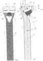
- Figs. 1 and 2illustrate an embodiment of the bone screw 1 with a screw head 2 comprising a conical external thread 29.
- the bone screw 1includes a screw axis 6, a threaded shaft 10, a screw head 2 and a rear end 8 at a proximal end thereof.
- the screw head 2comprises a through hole 9 penetrating through the screw head 2 and having a through hole axis 7 cutting the screw axis 6 under an acute angle ⁇ .
- the through hole axis 7cuts the screw axis 2 at a depth T measured from the rear end 8 of the bone screw 1.
- the through hole 9has a conical internal thread 11.
- a second screw 50( Figs. 16 and 17 ) can be inserted into the through hole 9 coaxially to the through hole axis 7.
- the second screw 50has a conically threaded head 51 which is engagable with the conical internal thread 11 in the through hole 9.
- the screw head 2includes a concave seat 14 for releasably coupling a surgical instrument or tool to the bone screw 1.
- the concave seat 14comprises a transverse channel 5 and a centrally located recess 3.
- the transverse channel 5comprises a channel axis 101 located at a depth T C measured from the rear end 8 of the bone screw 1 and diametrically extending across the screw head 2.
- the channel axis 101cuts the screw axis 6 through the point where the through hole axis 7 cuts the screw axis 6.
- the transverse channel 5is open at the rear end 8 of the bone screw 1 and the transverse channel 5 has a U-shaped cross-section with a semicircular bottom 100 orthogonal to the channel axis 101.
- the semicircular bottom 100has a radius of curvature r C wherein a center of an edge the semicircular bottom 100 of the transverse channel 5 is located on the channel axis 101.
- the depth T Cis equal to the depth T of the point where the through hole axis 7 cuts the screw axis 1.
- the semicircular bottom 100defines a seat coaxially to the recess 3 for rotatably receiving cylindrical pins 25 of an aiming guide 23 ( Fig. 10 ) which have a pin diameter equal to twice the radius of curvature r C of the semicircular bottom 100 of the transverse channel 5.
- the recess 3has a spherical shape with a radius of the sphere R and a centre 4 coinciding with the point at which the screw axis 6 and the through hole axis 7 intersect. So the recess 3 forms a pivot bearing for rotatably supporting and guiding a complementarily spherically shaped male connector 232 of an aiming guide 23 ( Fig. 10 ).
- the channel axis 101cuts the screw axis 6 at the point where the centre 4 of the spherically shaped recess 3 is located on the screw axis 6 and that the pivot pins 25 of the aiming guide 23 fit in the transverse channel 5 rotatably about the channel axis 101 the polyaxial pivot bearing formed by the ball-and-socket joint is limited to an uniaxial pivot bearing.
- the aiming guide 23can only pivot about the channel axis 101 which is orthogonal to a plane defined by the screw axis 6 and the through hole axis 7 of the through hole 9 for the second screw 50.
- the recess 3has a constriction 31 at the rear end 8 of the bone screw 1 so that the recess 3 forms a female connector for a snap-lock connection.
- the recess 3includes a depression 12 which forms a wall portion 121 with the shape of a surface section of a circular cylinder with a radius r ⁇ R.
- the axis of the circular cylindercoincides with the through hole axis 7 of the through hole 9.
- the depression 12forms a stop for the rotation of an aiming guide 23 about the channel axis 101 when the aiming guide 23 is coupled to the screw head 2 of the bone screw 1. By means of the stop the aiming guide 23 can be exactly aligned with the through hole 9.
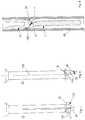
- Figs. 3 to 6illustrate an embodiment of the screwdriver 13 to be used with the bone screw 1 according to Figs. 1 and 2 .
- the screwdriver 13comprises a longitudinal axis 130, a shaft 131, a front end 135 at a distal end thereof and a male connector 132 which can be coupled to the above embodiment of the bone screw 1.
- the connector 132is essentially complementarily formed to the concave seat 14 in the screw head 2 of the bone screw 1.
- the connector 132includes a partially spherical tip 17 the cross-sectional area of which in a plane perpendicular to the longitudinal axis decreases toward the shaft 131 (i.e., toward the front end 135).
- a cross-sectional area of the spherical tip 17 at an end adjacent to the shaft 131 and at the front end 135is smaller than a cross-sectional area of a mid-section of the spherical tip 17.
- the tapering of the spherical tip 17 towards the shaft 131forms a curved contact shoulder 138 which abuts the constriction 31 of the recess 3 at the rear end 8 of the bone screw 1.
- the screwdriver 13further comprises a longitudinal slot 20 open at the front end 135 to form the tip 17 as an elastic male connector for a snap-lock connection between the tip 17 and the recess 3 in the screw head 2 of the bone screw 1.
- the longitudinal slot 20is arranged orthogonal to a plane defined by the longitudinal axis 130 and the central axis 136 and penetrates through the shaft 131.
- the connector 132further includes two driving protrusions 18 extending laterally from the spherical tip 17 in either direction and which are coaxially arranged on a central axis 136.
- the driving protrusions 18are circular-cylindrically shaped with a cylinder axis coinciding with the central axis 136.
- the connector 132additionally comprises an axial stop 21 which is located between the shaft 131 and the connector 132 at a distance T measured from the central axis 136 towards the shaft 131.
- the axial stop 21abuts the rear end 8 of the bone screw 1 allowing to keep the screwdriver 13 exactly coaxially to the screw axis 6 of the bone screw 1.
- the shaft 131 and the connector 132comprise a coaxial through bore 134 with an internal thread 137 for engaging an external thread arranged on a locking pin 35 ( Fig.
- the embodiment of the screwdriver 13 illustrated in Figs. 7 to 9differs from the embodiment of Figs. 3 to 6 only therein that the male connector 132 further includes a nose 34 extending from the tip 17 in a direction towards the front end 135.
- the nose 34has a nose axis 38 extending under the angle ⁇ with respect to the longitudinal axis 130 of the screwdriver 13.
- the screwdriver 13can be coupled to the bone screw 1 in only one rotative position, namely the one position where the nose 34 engages the through hole 9 in the bone screw 1 in such a manner that the nose axis 38 coincides with the through hole axis 7.
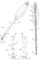
- Fig. 10illustrates an embodiment of the aiming guide 23 to be used with the bone screw 1 according to Figs. 1 and 2 .
- the aiming guide 23comprises a longitudinal axis 230, a coaxial through bore 28, a guide sleeve 26, a front end 235 and a male connector 232 terminally arranged at the front end 235.
- the connector 232is essentially complementarily formed to the seat 14 in the screw head 2 of the bone screw 1.
- the connector 232includes a spherically shaped tip 231 which tapers inward toward the front end 235 and toward the guide sleeve 26 forming a ball-and-socket joint with the recess 3 of the above described embodiment of the bone screw 1.
- the spherically shaped tip 231has a radius of the sphere R and a centre 233 located on the longitudinal axis 230.
- the connector 232includes two pins 25 diametrically projecting over the tip 231 in either direction and which are coaxially arranged on a central axis 234 which extends orthogonal to the longitudinal axis 230 and which cuts the longitudinal axis 230 through the centre 233 of the spherically shaped tip 231.
- the pins 25are circular-cylindrically shaped with a cylinder axis coinciding with the central axis 234 so as to form axles coaxially and rotatably insertable in the transverse channel 5 in the screw head 2 of the bone screw 1.
- the aiming guide 23further comprises a longitudinal slot 27 open at the front end 235 to form the tip 231 as an elastic male connector for a snap-lock connection between the aiming guide 23 and a the spherical recess 3 in the screw head 2 of the bone screw 1.
- the longitudinal slot 27is arranged orthogonal to a plane defined by the longitudinal axis 230 and the central axis 234 and penetrates through the guide sleeve 26.
- a cylindrical collar 33is arranged coaxially to the longitudinal axis 230 and which has a radius r ⁇ R.
- a drill guide 36can be inserted in the through bore 28 in the aiming guide 23.
- the drill guide 36has a conical tip 37 which fits into the tapered through hole 9 in such a manner that the drill guide 36 is exactly aligned with the through hole axis 7 of the through hole 9 in the bone screw 1.
- Figs. 11 to 17show a method for bone fixation by using an intramedullary nail 300 and bone screws 1 along with second screws 50, which are briefly described in the following section.
- the intramedullary nail 300comprises a nail axis 303, a proximal end 305, a peripheral surface 304, a number of proximal locking holes 301 with a most proximal locking hole 302 and a number of distal locking holes 306.
- the proximal and distal locking holes 301, 306extend transverse to the nail axis 303.
- the intramedullary nail 300is inserted into the intramedullary canal of a long bone in such a manner that the portion of the intramedullary nail 300 containing the distal locking holes 306 is located in a distal bone fragment and the portion containing the proximal locking holes 301 is located in the proximal bone fragment.
- a bone screw 1each is driven through all or a number of selected proximal and distal locking holes 301, 306.
- the bone screws 1can be driven through all or the selected proximal and distal locking holes 301, 306 and the second screws 50 can be anchored in the bone.
- the second screws 50could be driven into the proximal and distal locking holes 301, 306 and the bone screws 1 could be anchored in the bone.
- the method for inserting the bone screws 1 into the nail 300 and anchoring the second screws 50 into the bonecomprises the steps of making an incision into the tissue surrounding a bone to be treated and positioning an intramedullary nail 300 in the bone.
- An aiming device(not shown) to the proximal end 305 of the intramedullary nail 300, wherein the aiming device has guide bores for inserting guide sleeves and/or tissue protection tubes 40 coaxially to each of all or of a number of selected proximal and/or distal locking holes 301, 306.
- a tissue protection tube 40( Figs.
- a first bore holeis then drilled into a bone for insertion of a bone screw 1 through the selected proximal or distal locking hole 301, 306 by using the aiming device, wherein the first bore hole is aligned with the selected proximal or distal locking hole 301, 306.
- the bore holeextends on either side of the intramedullary nail 300 in such a manner that a bone screw 1 can penetrate through the selected proximal or distal locking hole 301, 306 of the intramedullary nail 300 when the bone screw 1 is anchored in the bone.
- the bone screw 1is coupled to the connector 132 of the screwdriver 13 by using the snap-lock connection between the bone screw 1 and the screwdriver 13 and advancing the bone screw 1 through the tissue protection tube 40.
- the bone screw 1is then screwed into the bone using the screwdriver 13. Once the bone screw 1 is screwed into the bone, the screwdriver 13 may be removed. The above-described steps may be repeated until a bone screw 1 has been inserted into all of the desired proximal and/or distal locking holes 301, 302.
- the aiming guide 23is then inserted through the protection tube 40, as shown in Fig. 11 , to attach the aiming guide 23 to the bone screw 1 using the snap-lock connection between the tip 231 of the aiming device 23 and the recess 3 in the screw head 2 of the bone screw 1 such that the longitudinal axis 230 of the aiming guide 23 is aligned with the screw axis 6 of the bone screw 1.
- the tissue protection tube 40 and the aiming devicemay be removed and the and the aiming guide 23 pivoted about the central axis 234 defined by the pins 25 arranged at the connector 232 of the aiming guide 23 until the collar 33 of the aiming guide 23 abuts a stop in the recess 3 in the screw head 2 of the bone screw 1 so that the longitudinal axis 230 of the aiming guide 23 is aligned with the through hole axis 7 of the through hole 9 in the bone screw 1 ( Fig. 12 ).
- the stopis formed by the wall portion 121 of the depression 12 in the recess 3 in the screw head 2 of the bone screw 1.
- the drill guide 36is then inserted into the through bore 28 in the aiming guide 23 ( Fig.
- a second bore holeis drilled into the bone using the drill guide 36 as a guide for the drill bit 39.
- the drill guide 36is removed and the second screw 50 is inserted through the through bore 28 in the aiming guide 23 ( Fig. 15 ) and advanced through the second screw 50 into the bone ( Fig. 16 ).
- the aiming guide 23may then be removed and the steps described above repeated until a second screw 50 each is anchored in the bone passing through the through hole 9 of each of the bone screws 1. Once all of the desired bone screws 1 and second screws 50 have been inserted into the bone, the incision may be closed.
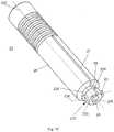
- an alternate embodiment of the assembly of the present inventionis substantially similar to the assembly described above in regard to Figs. 1 - 17 , comprising a first bone screw 1', a second bone screw 50' and a screwdriver 13'.
- the screwdriver 13'combines elements of the screwdriver 13 and the aiming guide 23, as described above, such that two separate devices are not required for insertion of the first bone screw 1' and for aiming the second bone screw 50'.
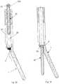
- the screwdriver 13'includes a connector 132' at a distal end 135' thereof, which extends around a head 2' of the first bone screw 1' rather than within a recess thereof.
- the first bone screw 1'extends along a first axis 6' and includes a head 2', which has an exterior surface that is at least partially spherical.
- the exterior surfacemay also include portions that are substantially planar permitting a torsional force to be applied thereto via the screwdriver 13'.
- the first bone screw 1'includes a through hole 9' extending along a second axis 7' to receive the second screw 50' therein.
- the second screw 50'is substantially similar to the second screw 50' described above.
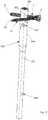
- the screwdriver 13'includes a shaft 131' extending along a longitudinal axis 130' with a connector 132' formed at the distal end 135' thereof.
- the screwdriver 13'also includes a channel 28' extending therethrough along the longitudinal axis 130' sized and shaped to permit the second bone screw 50' to be inserted therethrough.
- the connector 132'includes a partially spherical interior surface 231' sized and shaped to receive the head 2' of the first bone screw 1' therein.
- the connector 132'may be keyed (e.g., include planar portions corresponding to the planar portions of the head 2') permitting the screwdriver 13' to apply torsional forces to the bone screw 1' while also permitting the first bone screw 1' to pivot with respect to the screwdriver 13' via the partially spherical surfaces of the connector 132' and the head 2'.
- the interior surface 231'may receive the head 2' via, for example, a snap fit.
- the head 2'may include pins extending radially outward therefrom, which are substantially similar to the pins 25 of the connector 232 of the aiming guide 23, and the connector 132' may include a transverse channel diametrically extending thereacross similarly to the channel 5 of the bone screw 1, as described above. It will be understood by those of skill in the art that such a configuration also permits the first bone screw 1' to be rotated via the screwdriver 13' while also permitting the first bone screw 1' to be pivoted relative thereto.
- the first and second bone screws 1', 50' and the screwdriver 13'may be used in a manner substantially similar to the method described above.
- the first bone screw 1'may be inserted into a desired one of the proximal and/or distal locking holes 301, 306 of an intramedullary nail 300 inserted into the bone.
- a first bore holemay be drilled through the desired one of the first and second holes 301, 306 to accommodate the first bone screw 1'.
- the screwdriver 13'is coupled to the first bone screw 1' by receiving the head 2' within the connector 132'. In an initial configuration, the longitudinal axis 130' of the screwdriver 13' is coaxially aligned with the first axis 6' of the bone screw 1'.
- the first bone screw 1'is screwed into the desired one of the holes 301, 306 and the first bore hole via the screwdriver 13'.
- the screwdriver 13'is pivoted with respect to the first bone screw 1' about the head 2' until the channel 28' thereof is coaxially aligned with the second axis 7' of the through bore 9'.
- a second bore holemay be drilled into the bone through the channel 28' and through bore 9' to accommodate the second bone screw 50'.
- the second bone screw 50'may then be guided through the channel 28' and into through bore 9' to be advanced into the second bore hole in the bone. It will be understood by those of skill in the art that the above-described steps may be repeated, as desired, until a desired number of first and second bone screws 1', 50' have been inserted into the bone.
Landscapes
- Health & Medical Sciences (AREA)
- Orthopedic Medicine & Surgery (AREA)
- Surgery (AREA)
- Life Sciences & Earth Sciences (AREA)
- Biomedical Technology (AREA)
- Public Health (AREA)
- Veterinary Medicine (AREA)
- Engineering & Computer Science (AREA)
- Nuclear Medicine, Radiotherapy & Molecular Imaging (AREA)
- Heart & Thoracic Surgery (AREA)
- Medical Informatics (AREA)
- Molecular Biology (AREA)
- Animal Behavior & Ethology (AREA)
- General Health & Medical Sciences (AREA)
- Neurology (AREA)
- Dentistry (AREA)
- Oral & Maxillofacial Surgery (AREA)
- Surgical Instruments (AREA)
Description
- The present invention generally relates to a system comprising a bone screw and an aiming guide for drilling a hole in a bone. More particularly, the invention relates to a system with a bone screw including a second screw.
- In the field of orthopedic surgery bone fixation devices using bone screws are commonly used. These bone fixation devices include bone plates, intervertebral implants or intramedullary nails by means of which two or more bones or bone fragments are fixed relative to each other. Typically, the bone fixation devices comprise bone anchors mostly in the form of bone screws, pins or nails by means of which the bones or bone fragments are fixed to the bone plate, intervertebral implant or intramedullary nail and consequently fixed relative to each other. One problem that can arise in case of the above mentioned bone fixation devices is that the bone screws, pins or nails can for instance become dislodged in the bone or in the bone plate, intervertebral implant or intramedullary nail during normal movements of the patient.
- From
WO 2009/120852 a universal anchor for attaching objects to bone tissue is known. The document discloses an anchoring device for attaching an object to a bone. The device comprises an anchoring member having proximal and distal ends, the proximal end adapted to hold the object to the bone while the distal end is in the bone. The device also comprises a locking member having proximal and distal ends, the proximal end adapted to secure the anchoring member into the bone and to oppose its pull-out or loosening, by stopping its backing or preventing its unscrewing while the distal end is in the bone. First and second fasteners are disclosed, the first fastener adapted to fit to the proximal end of the anchoring member, and the second fastener adapted to fit to the proximal end of the locking member. The end of the second fastener can have an angle that matches an angle of the locking member. - Document
WO 2010/065855 , which was published after the priority date of the present invention, is directed to an anchor-in-anchor system for use in bone fixation. The fixation system includes a first bone anchor having a shaft for fixation to underlying bone, and a head that defines an internal bore. A second bone anchor extends through the bore and into underlying bone. The head of the first anchor includes an annular body that defines a radially inner surface, an opposing radially outer surface, a proximal end and a distal end. The annular body includes a plurality of circumferentially spaced retention tabs that extend up from the distal end. Thus, terminal ends of the retention tabs are disposed at the proximal end of the head. The retention tabs are configured such that circumferentially adjacent tabs are separated by a slot that extends distally into the proximal end of the head in a direction toward, but not through, a base of the head. The head further defines a bore extending centrally through the annular body along a central bore axis. The central axis extends in a direction angularly offset with respect to the longitudinal axis. The shaft is coupled to the base, and extends radially outward and down from the radially outer surface of the base such that the shaft does not interfere with the bore. The head includes a plurality of helical threads in the bore that extend radially inward from the radially inner surface of the annular body, including the tabs and the base. The central axis of the bore intersects with the longitudinal axis of the shaft so as to define an acute angle. The bore of the first bone anchor is configured to receive the second bone anchor, such that the first and second bone anchors can be fastened together. - Thus, there remains a need for an improved bone anchor device for use in bone fixation that allows to drill a hole for a securing screw into a bone under a particular angle with respect to the axis of a bone fastener and to insert the securing screw in a guided manner.
- The present invention relates to a system as defined in
claim 1, which comprises a bone screw and an aiming guide. Preferred embodiments are defined in the dependent claims. - An exemplary embodiment of the present invention will be described in the following by way of example and with reference to the accompanying drawings in which:
Fig. 1 illustrates a longitudinal section of an embodiment of the bone screw according to the invention;Fig. 2 illustrates a lateral view of the embodiment of the bone screw ofFig. 1 ;Fig. 3 illustrates a perspective view of an embodiment of the screwdriver according to the invention;Fig. 4 illustrates a longitudinal section of the embodiment of the screwdriver ofFig. 3 ;Fig. 5 illustrates a lateral view of the embodiment of the screwdriver ofFig. 3 ;Fig. 6 illustrates a lateral view of the embodiment of the screwdriver ofFig. 3 which is orthogonal to the lateral view ofFig. 5 ;Fig. 7 illustrates a lateral view of another embodiment of the screwdriver according to the invention;Fig. 8 illustrates a lateral view of the embodiment of the screwdriver ofFig. 7 which is orthogonal to the lateral view ofFig. 7 ;Fig. 9 illustrates a partial section through the embodiment of the screwdriver ofFigs. 7 and 8 and a bone screw attached thereto;Fig. 10 illustrates a perspective view of an embodiment of the aiming guide according to the invention;Fig. 11 illustrates a longitudinal section through the embodiment of the aiming guide ofFig. 10 and a bone screw coaxially attached thereto;Fig. 12 illustrates a longitudinal section through the embodiment of the aiming guide ofFig. 10 and a bone screw attached thereto under the angle α;Fig. 13 illustrates a longitudinal section through the embodiment of the aiming guide ofFig. 10 and a bone screw attached thereto under the angle α and together with a drill guide inserted in the aiming guide and a drill bit;Fig. 14 illustrates a section through the aiming device and the drill guide ofFig. 13 ;Fig. 15 illustrates a longitudinal section through the embodiment of the aiming guide ofFig. 10 and a bone screw attached thereto under the angle α and together with a second screw inserted in the aiming guide;Fig. 16 illustrates a longitudinal section through the embodiment of the aiming guide ofFig. 10 and a bone screw attached thereto under the angle α and together with a second screw firmly secured in the through hole in the screw head of the bone screw; andFig. 17 illustrates an intramedullary nail together with a bone screw and a second screw according to an embodiment of the method for bone fixation according the invention.Fig. 18 illustrates a lateral view of a system according to an alternate embodiment of the present invention, in a first configuration.Fig. 19 illustrates a lateral view of the system ofFig. 18 , in a second configuration.Fig. 20 illustrates a cross-sectional lateral view of the system ofFig. 18 , in the second configuration.Fig. 21 illustrates an enlarged cross-sectional lateral view of a portion of the system ofFig. 18 .- The present invention may be further understood with reference to the following description and the appended drawings, wherein like elements are referred to with the same reference numerals. The present disclosure relates to bone screw assemblies and instruments for implantation of the same as well as to an associated method for implantation of the bone screw assembly using the instruments. In particular, the disclosure relates to a system and method facilitating implantation of a first bone screw, including a through hole extending through a head portion thereof along a through hole axis, and a second screw inserted into the through hole along the through hole axis such that the first and second bone screws are implanted into a bone in a stable configuration.
Figs. 1 and 2 illustrate an embodiment of thebone screw 1 with ascrew head 2 comprising a conicalexternal thread 29. Thebone screw 1 includes ascrew axis 6, a threadedshaft 10, ascrew head 2 and arear end 8 at a proximal end thereof. Thescrew head 2 comprises a throughhole 9 penetrating through thescrew head 2 and having a throughhole axis 7 cutting thescrew axis 6 under an acute angle α. The throughhole axis 7 cuts thescrew axis 2 at a depth T measured from therear end 8 of thebone screw 1. The throughhole 9 has a conicalinternal thread 11. A second screw 50 (Figs. 16 and17 ) can be inserted into the throughhole 9 coaxially to the throughhole axis 7. Thesecond screw 50 has a conically threadedhead 51 which is engagable with the conicalinternal thread 11 in the throughhole 9. Thescrew head 2 includes aconcave seat 14 for releasably coupling a surgical instrument or tool to thebone screw 1. Theconcave seat 14 comprises atransverse channel 5 and a centrally locatedrecess 3. Thetransverse channel 5 comprises achannel axis 101 located at a depth TC measured from therear end 8 of thebone screw 1 and diametrically extending across thescrew head 2. Thechannel axis 101 cuts thescrew axis 6 through the point where the throughhole axis 7 cuts thescrew axis 6. Further, thetransverse channel 5 is open at therear end 8 of thebone screw 1 and thetransverse channel 5 has a U-shaped cross-section with asemicircular bottom 100 orthogonal to thechannel axis 101. Thesemicircular bottom 100 has a radius of curvature rC wherein a center of an edge thesemicircular bottom 100 of thetransverse channel 5 is located on thechannel axis 101. The depth TC is equal to the depth T of the point where the throughhole axis 7 cuts thescrew axis 1. Thesemicircular bottom 100 defines a seat coaxially to therecess 3 for rotatably receivingcylindrical pins 25 of an aiming guide 23 (Fig. 10 ) which have a pin diameter equal to twice the radius of curvature rC of thesemicircular bottom 100 of thetransverse channel 5.- The
recess 3 has a spherical shape with a radius of the sphere R and a centre 4 coinciding with the point at which thescrew axis 6 and the throughhole axis 7 intersect. So therecess 3 forms a pivot bearing for rotatably supporting and guiding a complementarily spherically shapedmale connector 232 of an aiming guide 23 (Fig. 10 ). Due to the facts that thechannel axis 101 cuts thescrew axis 6 at the point where the centre 4 of the spherically shapedrecess 3 is located on thescrew axis 6 and that the pivot pins 25 of the aimingguide 23 fit in thetransverse channel 5 rotatably about thechannel axis 101 the polyaxial pivot bearing formed by the ball-and-socket joint is limited to an uniaxial pivot bearing. When the aimingguide 23 is coupled to thebone screw 1 the aimingguide 23 can only pivot about thechannel axis 101 which is orthogonal to a plane defined by thescrew axis 6 and the throughhole axis 7 of the throughhole 9 for thesecond screw 50. This allows to position the aimingguide 23 in a first position coaxial to thescrew axis 6 of thebone screw 1 and in a second position coaxial to the throughhole axis 7 of the throughhole 9 for thesecond screw 50. Thus, it will be understood by those of skill in the art, that thesecond screw 50 may be precisely inserted into the throughhole 9 along throughhole axis 7, increasing a stability of thescrews - Furthermore, the
recess 3 has aconstriction 31 at therear end 8 of thebone screw 1 so that therecess 3 forms a female connector for a snap-lock connection. Additionally, therecess 3 includes adepression 12 which forms awall portion 121 with the shape of a surface section of a circular cylinder with a radius r ≤ R. The axis of the circular cylinder coincides with the throughhole axis 7 of the throughhole 9. Thedepression 12 forms a stop for the rotation of an aimingguide 23 about thechannel axis 101 when the aimingguide 23 is coupled to thescrew head 2 of thebone screw 1. By means of the stop the aimingguide 23 can be exactly aligned with the throughhole 9. Figs. 3 to 6 illustrate an embodiment of thescrewdriver 13 to be used with thebone screw 1 according toFigs. 1 and 2 . Thescrewdriver 13 comprises alongitudinal axis 130, ashaft 131, afront end 135 at a distal end thereof and amale connector 132 which can be coupled to the above embodiment of thebone screw 1. In order to releasably couple thescrewdriver 13 to thebone screw 1 theconnector 132 is essentially complementarily formed to theconcave seat 14 in thescrew head 2 of thebone screw 1. Theconnector 132 includes a partiallyspherical tip 17 the cross-sectional area of which in a plane perpendicular to the longitudinal axis decreases toward the shaft 131 (i.e., toward the front end 135). Thus, a cross-sectional area of thespherical tip 17 at an end adjacent to theshaft 131 and at thefront end 135 is smaller than a cross-sectional area of a mid-section of thespherical tip 17. The tapering of thespherical tip 17 towards theshaft 131 forms acurved contact shoulder 138 which abuts theconstriction 31 of therecess 3 at therear end 8 of thebone screw 1. Thescrewdriver 13 further comprises alongitudinal slot 20 open at thefront end 135 to form thetip 17 as an elastic male connector for a snap-lock connection between thetip 17 and therecess 3 in thescrew head 2 of thebone screw 1. Thelongitudinal slot 20 is arranged orthogonal to a plane defined by thelongitudinal axis 130 and thecentral axis 136 and penetrates through theshaft 131. Theconnector 132 further includes two drivingprotrusions 18 extending laterally from thespherical tip 17 in either direction and which are coaxially arranged on acentral axis 136. The drivingprotrusions 18 are circular-cylindrically shaped with a cylinder axis coinciding with thecentral axis 136. Theconnector 132 additionally comprises anaxial stop 21 which is located between theshaft 131 and theconnector 132 at a distance T measured from thecentral axis 136 towards theshaft 131. Theaxial stop 21 abuts therear end 8 of thebone screw 1 allowing to keep thescrewdriver 13 exactly coaxially to thescrew axis 6 of thebone screw 1. Theshaft 131 and theconnector 132 comprise a coaxial throughbore 134 with aninternal thread 137 for engaging an external thread arranged on a locking pin 35 (Fig. 4 ) which is insertable in the throughbore 134 in such a manner that the lockingpin 35 can be advanced towards thefront end 135 of thescrewdriver 13 in order to prevent thetip 17 from radially collapsing so that it can be firmly kept in therecess 3 in thescrew head 2 of thebone screw 1.- The embodiment of the
screwdriver 13 illustrated inFigs. 7 to 9 differs from the embodiment ofFigs. 3 to 6 only therein that themale connector 132 further includes anose 34 extending from thetip 17 in a direction towards thefront end 135. Thenose 34 has anose axis 38 extending under the angle α with respect to thelongitudinal axis 130 of thescrewdriver 13. Thus, thescrewdriver 13 can be coupled to thebone screw 1 in only one rotative position, namely the one position where thenose 34 engages the throughhole 9 in thebone screw 1 in such a manner that thenose axis 38 coincides with the throughhole axis 7. Fig. 10 illustrates an embodiment of the aimingguide 23 to be used with thebone screw 1 according toFigs. 1 and 2 . The aimingguide 23 comprises alongitudinal axis 230, a coaxial throughbore 28, aguide sleeve 26, afront end 235 and amale connector 232 terminally arranged at thefront end 235. To releasably couple the aimingguide 23 to thebone screw 1 theconnector 232 is essentially complementarily formed to theseat 14 in thescrew head 2 of thebone screw 1. Theconnector 232 includes a sphericallyshaped tip 231 which tapers inward toward thefront end 235 and toward theguide sleeve 26 forming a ball-and-socket joint with therecess 3 of the above described embodiment of thebone screw 1. The sphericallyshaped tip 231 has a radius of the sphere R and acentre 233 located on thelongitudinal axis 230. Additionally, theconnector 232 includes twopins 25 diametrically projecting over thetip 231 in either direction and which are coaxially arranged on acentral axis 234 which extends orthogonal to thelongitudinal axis 230 and which cuts thelongitudinal axis 230 through thecentre 233 of the sphericallyshaped tip 231. Thepins 25 are circular-cylindrically shaped with a cylinder axis coinciding with thecentral axis 234 so as to form axles coaxially and rotatably insertable in thetransverse channel 5 in thescrew head 2 of thebone screw 1. The aimingguide 23 further comprises alongitudinal slot 27 open at thefront end 235 to form thetip 231 as an elastic male connector for a snap-lock connection between the aimingguide 23 and a thespherical recess 3 in thescrew head 2 of thebone screw 1. Thelongitudinal slot 27 is arranged orthogonal to a plane defined by thelongitudinal axis 230 and thecentral axis 234 and penetrates through theguide sleeve 26. Between thetip 231 and the guide sleeve 26 acylindrical collar 33 is arranged coaxially to thelongitudinal axis 230 and which has a radius r ≤ R.- As illustrated in
Figs. 13 and 14 adrill guide 36 can be inserted in the throughbore 28 in the aimingguide 23. Thedrill guide 36 has aconical tip 37 which fits into the tapered throughhole 9 in such a manner that thedrill guide 36 is exactly aligned with the throughhole axis 7 of the throughhole 9 in thebone screw 1. Figs. 11 to 17 show a method for bone fixation by using anintramedullary nail 300 andbone screws 1 along withsecond screws 50, which are briefly described in the following section. Theintramedullary nail 300 comprises anail axis 303, aproximal end 305, aperipheral surface 304, a number of proximal locking holes 301 with a mostproximal locking hole 302 and a number of distal locking holes 306. The proximal and distal locking holes 301, 306 extend transverse to thenail axis 303. Theintramedullary nail 300 is inserted into the intramedullary canal of a long bone in such a manner that the portion of theintramedullary nail 300 containing the distal locking holes 306 is located in a distal bone fragment and the portion containing the proximal locking holes 301 is located in the proximal bone fragment. In order to lock theintramedullary nail 300 in the bone abone screw 1 each is driven through all or a number of selected proximal and distal locking holes 301, 306. Using thebone screw 1 according to the invention the bone screws 1 can be driven through all or the selected proximal and distal locking holes 301, 306 and thesecond screws 50 can be anchored in the bone. It should be appreciated that instead of driving the bone screws 1 into the proximal and distal locking holes 301, 306 thesecond screws 50 could be driven into the proximal and distal locking holes 301, 306 and the bone screws 1 could be anchored in the bone.- The method for inserting the bone screws 1 into the
nail 300 and anchoring thesecond screws 50 into the bone comprises the steps of making an incision into the tissue surrounding a bone to be treated and positioning anintramedullary nail 300 in the bone. An aiming device (not shown) to theproximal end 305 of theintramedullary nail 300, wherein the aiming device has guide bores for inserting guide sleeves and/ortissue protection tubes 40 coaxially to each of all or of a number of selected proximal and/or distal locking holes 301, 306. A tissue protection tube 40 (Figs. 9 and11 ) is inserted into a selected guide bore in the aiming device coaxially to one of the proximal and distal locking holes 301, 306 until the front end of thetissue protection tube 40 contacts the surface of the bone. A first bore hole is then drilled into a bone for insertion of abone screw 1 through the selected proximal ordistal locking hole distal locking hole intramedullary nail 300 in such a manner that abone screw 1 can penetrate through the selected proximal ordistal locking hole intramedullary nail 300 when thebone screw 1 is anchored in the bone. Thebone screw 1 is coupled to theconnector 132 of thescrewdriver 13 by using the snap-lock connection between thebone screw 1 and thescrewdriver 13 and advancing thebone screw 1 through thetissue protection tube 40. Thebone screw 1 is then screwed into the bone using thescrewdriver 13. Once thebone screw 1 is screwed into the bone, thescrewdriver 13 may be removed. The above-described steps may be repeated until abone screw 1 has been inserted into all of the desired proximal and/or distal locking holes 301, 302. - The aiming
guide 23 is then inserted through theprotection tube 40, as shown inFig. 11 , to attach the aimingguide 23 to thebone screw 1 using the snap-lock connection between thetip 231 of the aimingdevice 23 and therecess 3 in thescrew head 2 of thebone screw 1 such that thelongitudinal axis 230 of the aimingguide 23 is aligned with thescrew axis 6 of thebone screw 1. Thetissue protection tube 40 and the aiming device may be removed and the and the aimingguide 23 pivoted about thecentral axis 234 defined by thepins 25 arranged at theconnector 232 of the aimingguide 23 until thecollar 33 of the aimingguide 23 abuts a stop in therecess 3 in thescrew head 2 of thebone screw 1 so that thelongitudinal axis 230 of the aimingguide 23 is aligned with the throughhole axis 7 of the throughhole 9 in the bone screw 1 (Fig. 12 ). The stop is formed by thewall portion 121 of thedepression 12 in therecess 3 in thescrew head 2 of thebone screw 1. Thedrill guide 36 is then inserted into the throughbore 28 in the aiming guide 23 (Fig. 13 ) and a second bore hole is drilled into the bone using thedrill guide 36 as a guide for thedrill bit 39. Once the second bore hole has been drilled, thedrill guide 36 is removed and thesecond screw 50 is inserted through the throughbore 28 in the aiming guide 23 (Fig. 15 ) and advanced through thesecond screw 50 into the bone (Fig. 16 ). The aimingguide 23 may then be removed and the steps described above repeated until asecond screw 50 each is anchored in the bone passing through the throughhole 9 of each of the bone screws 1. Once all of the desiredbone screws 1 andsecond screws 50 have been inserted into the bone, the incision may be closed. - As shown in
Figs. 18 - 21 , an alternate embodiment of the assembly of the present invention is substantially similar to the assembly described above in regard toFigs. 1 - 17 , comprising a first bone screw 1', a second bone screw 50' and a screwdriver 13'. The screwdriver 13', however, combines elements of thescrewdriver 13 and the aimingguide 23, as described above, such that two separate devices are not required for insertion of the first bone screw 1' and for aiming the second bone screw 50'. In addition, the screwdriver 13' includes a connector 132' at a distal end 135' thereof, which extends around a head 2' of the first bone screw 1' rather than within a recess thereof. - The first bone screw 1' extends along a first axis 6' and includes a head 2', which has an exterior surface that is at least partially spherical. The exterior surface may also include portions that are substantially planar permitting a torsional force to be applied thereto via the screwdriver 13'. Similarly to the
bone screw 1, the first bone screw 1' includes a through hole 9' extending along a second axis 7' to receive the second screw 50' therein. The second screw 50' is substantially similar to the second screw 50' described above. - The screwdriver 13' includes a shaft 131' extending along a longitudinal axis 130' with a connector 132' formed at the distal end 135' thereof. The screwdriver 13' also includes a channel 28' extending therethrough along the longitudinal axis 130' sized and shaped to permit the second bone screw 50' to be inserted therethrough. The connector 132' includes a partially spherical interior surface 231' sized and shaped to receive the head 2' of the first bone screw 1' therein. In one embodiment, the connector 132' may be keyed (e.g., include planar portions corresponding to the planar portions of the head 2') permitting the screwdriver 13' to apply torsional forces to the bone screw 1' while also permitting the first bone screw 1' to pivot with respect to the screwdriver 13' via the partially spherical surfaces of the connector 132' and the head 2'. The interior surface 231' may receive the head 2' via, for example, a snap fit.
- In an alternative embodiment, the head 2' may include pins extending radially outward therefrom, which are substantially similar to the
pins 25 of theconnector 232 of the aimingguide 23, and the connector 132' may include a transverse channel diametrically extending thereacross similarly to thechannel 5 of thebone screw 1, as described above. It will be understood by those of skill in the art that such a configuration also permits the first bone screw 1' to be rotated via the screwdriver 13' while also permitting the first bone screw 1' to be pivoted relative thereto. - The first and second bone screws 1', 50' and the screwdriver 13' may be used in a manner substantially similar to the method described above. In particular, the first bone screw 1' may be inserted into a desired one of the proximal and/or distal locking holes 301, 306 of an
intramedullary nail 300 inserted into the bone. A first bore hole may be drilled through the desired one of the first andsecond holes holes - The scope of the present application is not intended to be limited to the particular embodiments of the process, machine, manufacture, composition of matter, means, methods and steps described in the specification. As one of ordinary skill in the art will readily appreciate from the disclosure of the present invention, processes, machines, manufacture, composition of matter, means, methods, or steps, presently existing or later to be developed that perform substantially the same function or achieve substantially the same result as the corresponding embodiments described herein may be utilized according to the present invention.
- It will be appreciated by those skilled in the art that various modifications and alterations of the invention can be made without departing from the broad scope of the appended claims. Some of these have been discussed above and others will be apparent to those skilled in the art.
Claims (13)
- A system comprising a bone screw (1) and an aiming guide (23) for drilling a hole in a bone;
in which the bone screw (1) comprises:a screw shaft (10) extending longitudinally along a screw axis (6);a screw head (2) extending from a proximal end of the screw shaft (10); anda through hole (9) defining a through hole axis (7) and extending through the screw head (2), the through hole axis (7) intersecting the screw axis (6) at an acute angle α, the through hole (9) being adapted to receive therein a second screw (50) and tapering from a first end at a proximal end of the screw head (2) to a second end opening to an outer surface of the bone screw (1);in which the screw head (2) has a concave seat (14) comprising a channel (5) and a centrally located recess (3), the channel (5) disposed at the first end of the through hole (9) and extending from the outer surface of the bone screw (1) transversely through the screw head (2) along a channel axis (101) that is substantially perpendicular to the screw axis (6), the channel (5) being open at the proximal end of the bone screw (1);
in which the aiming guide (23) is for drilling a hole having an axis which coincides with the through hole axis (7) of the through hole (9) in the screw head (2) of the bone screw (1);
and in which the aiming guide (23) comprises:a guide sleeve (26);a coaxial through bore (28); anda male connector (232) terminally arranged at a front end (235) of the aiming guide (23) for coupling to the recess (3) in the screw head (2), the connector (232) including a tip (231) a width of which decreases towards the front end (235) of the aiming guide (23) and two pins (25) diametrically projecting over the tip (231) in either direction and coaxially arranged on a central axis (234) which extends orthogonal to a longitudinal axis (230) of the aiming guide, wherein in at least a cross-section orthogonal to the central axis (234) the tip (231) has a circularly curved periphery with a radius (R) and a centre located on the longitudinal axis (230). - The system according to claim 1, wherein the recess (3) extends through a proximal end of the screw head (2), the recess (3) also configured to receive a portion of a surgical tool to be releasably coupled thereto and having a substantially circular edge centered at an intersection of the through hole axis (7) and the screw axis (6).
- The system according to claim 1, wherein the through hole (9) comprises an internal thread.
- The system according to claim 2, wherein the recess (3) has a constriction (31) at the proximal end of the screw head (2) to facilitate a snap connection between the bone screw (1) and the surgical tool.
- The system according to claim 4, wherein the recess (3) includes a depression (12)
traversing the constriction (31) and forming a wall portion forming a portion of one of a cylinder, cone and a prism an axis of which coincides with the through hole axis. - The system according to claim 1, wherein the channel axis intersects the screw axis at
the point at which the screw axis and the through hole axis intersect. - The system of any one of claims 1 to 6, in which the bone screw (1) is a first bone screw, and in which the system comprises a second bone screw (50) sized and shaped to be inserted through the through hole (9) of the first bone screw (1) along the through hole axis (7).
- The system according to claim 1, further comprising a screwdriver for a bone screw,
the screw driver including a shaft extending longitudinally from a distal end to a proximal end, the distal end including a male connector configured to be coupled to the recess in the screw head of the first bone screw, the connector including a tip tapering towards the distal end of the screwdriver and two driving protrusions extending from opposite sides of the tip along a central axis extending orthogonally to the longitudinal axis of the screwdriver, wherein the driving protrusions engage the channel in the screw head of the first bone screw, and wherein the tip has a substantially circular periphery centered on the longitudinal axis. - The system according to claim 8, wherein the male connector further comprises an axial stop a distance T from the central axis towards the shaft so that the stop contacts the rear end of the first bone screw when the connector is coupled to the recess in the screw head.
- The system according to claim 8, wherein the male connector further includes a nose projecting over the tip in a direction toward the distal end and at an acute angle with respect to the longitudinal axis of the screwdriver.
- The system according to claim 7, further comprising a drill guide insertable into the through hole.
- The system according to claim 11 , further comprising a screwdriver including a connector at a distal end thereof configured to receive the partially spherical screw head such that the first bone screw is pivotable between a first position in which the screw axis is substantially coaxial with a longitudinal axis of the screwdriver to a second position in which the through hole axis is coaxial with the longitudinal axis.
- The system according to claim 12, wherein the screwdriver further includes a channel extending therethrough along the longitudinal axis thereof such that when the first bone screw is in the second position, the channel is configured to guide the second bone screw therethrough and into the through hole of the first bone screw.
Applications Claiming Priority (2)
| Application Number | Priority Date | Filing Date | Title |
|---|---|---|---|
| US33423410P | 2010-05-13 | 2010-05-13 | |
| PCT/US2011/035760WO2011143116A1 (en) | 2010-05-13 | 2011-05-09 | Bone screw assembly and instruments for implantation of the same |
Publications (2)
| Publication Number | Publication Date |
|---|---|
| EP2568899A1 EP2568899A1 (en) | 2013-03-20 |
| EP2568899B1true EP2568899B1 (en) | 2017-01-04 |
Family
ID=44357965
Family Applications (1)
| Application Number | Title | Priority Date | Filing Date |
|---|---|---|---|
| EP11726248.5AActiveEP2568899B1 (en) | 2010-05-13 | 2011-05-09 | Bone screw assembly and instruments for implantation of the same |
Country Status (10)
| Country | Link |
|---|---|
| US (1) | US20110282398A1 (en) |
| EP (1) | EP2568899B1 (en) |
| JP (1) | JP5784710B2 (en) |
| KR (1) | KR101885506B1 (en) |
| CN (1) | CN102958462B (en) |
| BR (1) | BR112012028705B1 (en) |
| CA (1) | CA2797790A1 (en) |
| CO (1) | CO6660472A2 (en) |
| TW (1) | TW201200099A (en) |
| WO (1) | WO2011143116A1 (en) |
Families Citing this family (46)
| Publication number | Priority date | Publication date | Assignee | Title |
|---|---|---|---|---|
| WO2006034436A2 (en) | 2004-09-21 | 2006-03-30 | Stout Medical Group, L.P. | Expandable support device and method of use |
| EP2023864B1 (en) | 2006-05-01 | 2019-07-10 | Stout Medical Group, L.P. | Expandable support device |
| CN104068925B (en)* | 2008-03-26 | 2017-07-14 | 斯恩蒂斯有限公司 | For the universal anchor by physical attachment on bone tissue |
| US8882838B2 (en)* | 2008-06-05 | 2014-11-11 | DePuy Synthes Products, LLC | Articulating disc implant |
| CN102046111A (en) | 2008-06-05 | 2011-05-04 | 斯恩蒂斯有限公司 | Articulating disc implant |
| US9017329B2 (en) | 2008-06-24 | 2015-04-28 | Extremity Medical, Llc | Intramedullary fixation assembly and method of use |
| US20110230884A1 (en)* | 2008-06-24 | 2011-09-22 | Adam Mantzaris | Hybrid intramedullary fixation assembly and method of use |
| US8343199B2 (en) | 2008-06-24 | 2013-01-01 | Extremity Medical, Llc | Intramedullary fixation screw, a fixation system, and method of fixation of the subtalar joint |
| US8303589B2 (en) | 2008-06-24 | 2012-11-06 | Extremity Medical Llc | Fixation system, an intramedullary fixation assembly and method of use |
| US9044282B2 (en) | 2008-06-24 | 2015-06-02 | Extremity Medical Llc | Intraosseous intramedullary fixation assembly and method of use |
| US9289220B2 (en)* | 2008-06-24 | 2016-03-22 | Extremity Medical Llc | Intramedullary fixation assembly and method of use |
| US8328806B2 (en) | 2008-06-24 | 2012-12-11 | Extremity Medical, Llc | Fixation system, an intramedullary fixation assembly and method of use |
| US8313487B2 (en)* | 2008-06-24 | 2012-11-20 | Extremity Medical Llc | Fixation system, an intramedullary fixation assembly and method of use |
| WO2010056895A1 (en) | 2008-11-12 | 2010-05-20 | Stout Medical Group, L.P. | Fixation device and method |
| US20100211176A1 (en) | 2008-11-12 | 2010-08-19 | Stout Medical Group, L.P. | Fixation device and method |
| US9060808B2 (en) | 2008-12-05 | 2015-06-23 | DePuy Synthes Products, Inc. | Anchor-in-anchor system for use in bone fixation |
| JP5759900B2 (en) | 2008-12-05 | 2015-08-05 | ジンテス ゲゼルシャフト ミット ベシュレンクテル ハフツング | Anchor-in-anchor system for use in bone fixation |
| CN101947139B (en)* | 2010-10-21 | 2013-10-23 | 赵大国 | Bionic dental implant and abutment and seminal root thereof |
| EP2455014B1 (en)* | 2010-11-17 | 2015-08-12 | Hyprevention | Implantable device for preventive or interventive treatment of femur fractures, associated ancillary device |
| US9861411B2 (en) | 2011-06-28 | 2018-01-09 | Spinologics Inc. | Bone screw, and bone fixation system and method |
| US20130085535A1 (en)* | 2011-09-21 | 2013-04-04 | Flexmedex, LLC | Support device and method |
| BR112014011984B1 (en)* | 2011-11-18 | 2021-02-09 | Synthes Gmbh | bone fixation system |
| US20140343616A1 (en)* | 2013-04-22 | 2014-11-20 | Daniel Sellers | Arthrodesis compression device |
| CN103692279A (en)* | 2013-11-28 | 2014-04-02 | 黄勇 | Slotted cylinder head shaft screw |
| EP2918238B1 (en)* | 2014-03-14 | 2017-11-15 | Biedermann Technologies GmbH & Co. KG | Instrument for holding and inserting a bone anchor |
| US9649133B2 (en)* | 2014-11-11 | 2017-05-16 | Intrepid Orthopedics | Supplemental fixation screw |
| US10492838B2 (en) | 2015-07-13 | 2019-12-03 | IntraFuse, LLC | Flexible bone implant |
| US10485595B2 (en) | 2015-07-13 | 2019-11-26 | IntraFuse, LLC | Flexible bone screw |
| US10154863B2 (en) | 2015-07-13 | 2018-12-18 | IntraFuse, LLC | Flexible bone screw |
| US10499960B2 (en) | 2015-07-13 | 2019-12-10 | IntraFuse, LLC | Method of bone fixation |
| US9918763B2 (en)* | 2015-07-24 | 2018-03-20 | Warsaw Orthopedic, Inc. | Bone fixation element and methods of use |
| US10299847B2 (en)* | 2016-09-22 | 2019-05-28 | Globus Medical, Inc. | Systems and methods for intramedullary nail implantation |
| WO2019074696A1 (en)* | 2017-10-09 | 2019-04-18 | Conmed Corporation | Easy start cannulated bone screw |
| EP3905965B1 (en) | 2019-01-02 | 2024-11-27 | Duet Spine Holdings, LLC | Bone fixation system |
| US11026733B2 (en) | 2019-02-28 | 2021-06-08 | Warsaw Orthopedic, Inc. | Surgical system and method |
| KR102350764B1 (en)* | 2019-08-28 | 2022-01-14 | (주)오스테오닉 | Device for inserting screws |
| US11523854B2 (en)* | 2019-09-12 | 2022-12-13 | DePuy Synthes Products, Inc. | Driver and system for threaded intramedullary nail retaining endcaps |
| EP4009888B1 (en)* | 2019-10-09 | 2023-07-19 | Kaj Klaue | Bone nail |
| US12004782B2 (en) | 2020-03-26 | 2024-06-11 | Warsaw Orthopedic, Inc. | Instrument for locking orthopedic screws |
| FR3109076B1 (en)* | 2020-04-09 | 2022-03-11 | Lock In Sa | Extraction-friendly bone anchorage implant |
| US11627998B2 (en) | 2020-12-11 | 2023-04-18 | Warsaw Orthopedic, Inc. | Head position and driver combination instrument |
| US20220192720A1 (en)* | 2020-12-18 | 2022-06-23 | DePuy Synthes Products, Inc. | Screw-in-screw bone fixation system |
| US11291477B1 (en) | 2021-05-04 | 2022-04-05 | Warsaw Orthopedic, Inc. | Dorsal adjusting implant and methods of use |
| US11432848B1 (en) | 2021-05-12 | 2022-09-06 | Warsaw Orthopedic, Inc. | Top loading quick lock construct |
| US11712270B2 (en) | 2021-05-17 | 2023-08-01 | Warsaw Orthopedic, Inc. | Quick lock clamp constructs and associated methods |
| US11957391B2 (en) | 2021-11-01 | 2024-04-16 | Warsaw Orthopedic, Inc. | Bone screw having an overmold of a shank |
Citations (3)
| Publication number | Priority date | Publication date | Assignee | Title |
|---|---|---|---|---|
| JP2001252283A (en)* | 2000-03-10 | 2001-09-18 | Robert Reed Shokai Co Ltd | Rod fixing device |
| DE20314297U1 (en)* | 2003-09-12 | 2003-11-20 | AlloCon GmbH, 42929 Wermelskirchen | bone screw |
| WO2011100512A2 (en)* | 2010-02-11 | 2011-08-18 | Extremity Medical | An intraosseous intramedullary fixation assembly and method of use |
Family Cites Families (9)
| Publication number | Priority date | Publication date | Assignee | Title |
|---|---|---|---|---|
| AU757039B2 (en)* | 1999-09-08 | 2003-01-30 | Synthes Gmbh | Bone screw |
| CN1652823A (en)* | 2000-12-14 | 2005-08-10 | 控制释放系统公司 | Device and method for treating conditions of a joint |
| US6681662B2 (en)* | 2002-03-01 | 2004-01-27 | Bondhus Corporation | Tool with fastener engaging member |
| DE102004009429A1 (en)* | 2004-02-24 | 2005-09-22 | Biedermann Motech Gmbh | Bone anchoring element |
| US7909826B2 (en)* | 2005-03-24 | 2011-03-22 | Depuy Spine, Inc. | Low profile spinal tethering methods |
| WO2008122446A1 (en)* | 2007-04-10 | 2008-10-16 | Stryker Trauma Gmbh | Bone screw holding device |
| CN104068925B (en)* | 2008-03-26 | 2017-07-14 | 斯恩蒂斯有限公司 | For the universal anchor by physical attachment on bone tissue |
| US20110184470A1 (en)* | 2008-08-07 | 2011-07-28 | K2M, Inc. | Bone screw assembly |
| JP5759900B2 (en)* | 2008-12-05 | 2015-08-05 | ジンテス ゲゼルシャフト ミット ベシュレンクテル ハフツング | Anchor-in-anchor system for use in bone fixation |
- 2011
- 2011-05-09CACA2797790Apatent/CA2797790A1/ennot_activeAbandoned
- 2011-05-09KRKR1020127029322Apatent/KR101885506B1/enactiveActive
- 2011-05-09WOPCT/US2011/035760patent/WO2011143116A1/enactiveApplication Filing
- 2011-05-09JPJP2013510206Apatent/JP5784710B2/enactiveActive
- 2011-05-09CNCN201180023740.1Apatent/CN102958462B/enactiveActive
- 2011-05-09USUS13/103,697patent/US20110282398A1/ennot_activeAbandoned
- 2011-05-09EPEP11726248.5Apatent/EP2568899B1/enactiveActive
- 2011-05-09BRBR112012028705-2Apatent/BR112012028705B1/enactiveIP Right Grant
- 2011-05-13TWTW100116973Apatent/TW201200099A/enunknown
- 2012
- 2012-12-13COCO12226066Apatent/CO6660472A2/enactiveIP Right Grant
Patent Citations (3)
| Publication number | Priority date | Publication date | Assignee | Title |
|---|---|---|---|---|
| JP2001252283A (en)* | 2000-03-10 | 2001-09-18 | Robert Reed Shokai Co Ltd | Rod fixing device |
| DE20314297U1 (en)* | 2003-09-12 | 2003-11-20 | AlloCon GmbH, 42929 Wermelskirchen | bone screw |
| WO2011100512A2 (en)* | 2010-02-11 | 2011-08-18 | Extremity Medical | An intraosseous intramedullary fixation assembly and method of use |
Also Published As
| Publication number | Publication date |
|---|---|
| CN102958462A (en) | 2013-03-06 |
| KR101885506B1 (en) | 2018-08-07 |
| TW201200099A (en) | 2012-01-01 |
| EP2568899A1 (en) | 2013-03-20 |
| US20110282398A1 (en) | 2011-11-17 |
| JP2013526339A (en) | 2013-06-24 |
| BR112012028705B1 (en) | 2020-10-13 |
| JP5784710B2 (en) | 2015-09-24 |
| KR20130108066A (en) | 2013-10-02 |
| WO2011143116A1 (en) | 2011-11-17 |
| BR112012028705A2 (en) | 2017-08-08 |
| CA2797790A1 (en) | 2011-11-17 |
| CO6660472A2 (en) | 2013-04-30 |
| CN102958462B (en) | 2015-08-19 |
Similar Documents
| Publication | Publication Date | Title |
|---|---|---|
| EP2568899B1 (en) | Bone screw assembly and instruments for implantation of the same | |
| US8052726B2 (en) | Ilio-sacral connector system and method | |
| US10335214B2 (en) | Multiplexed screws | |
| US20090163963A1 (en) | Apparatus and Method for Implantation of Surgical Devices | |
| US9668759B2 (en) | Surgical drill guide having keyway for axial alignment of a fastener for use for an orthopedic plate | |
| EP2772212B1 (en) | Instrument for inserting a bone anchoring element and system of such an instrument and a polyaxial bone anchoring element | |
| EP3801322B1 (en) | Systems for fusion of anatomical joints | |
| US11576709B2 (en) | Bone fixation system and methods of use | |
| EP3727176B1 (en) | Bone screw with cutting tip | |
| EP3698744B1 (en) | Orthopedic implant screw | |
| US10258381B2 (en) | Conical end cap for intramedullary nail | |
| US20220192720A1 (en) | Screw-in-screw bone fixation system | |
| CN116669641A (en) | Locking trocar and method of use thereof |
Legal Events
| Date | Code | Title | Description |
|---|---|---|---|
| PUAI | Public reference made under article 153(3) epc to a published international application that has entered the european phase | Free format text:ORIGINAL CODE: 0009012 | |
| 17P | Request for examination filed | Effective date:20121020 | |
| AK | Designated contracting states | Kind code of ref document:A1 Designated state(s):AL AT BE BG CH CY CZ DE DK EE ES FI FR GB GR HR HU IE IS IT LI LT LU LV MC MK MT NL NO PL PT RO RS SE SI SK SM TR | |
| DAX | Request for extension of the european patent (deleted) | ||
| 17Q | First examination report despatched | Effective date:20150812 | |
| REG | Reference to a national code | Ref country code:DE Ref legal event code:R079 Ref document number:602011034030 Country of ref document:DE Free format text:PREVIOUS MAIN CLASS: A61B0017880000 Ipc:A61B0017860000 | |
| GRAP | Despatch of communication of intention to grant a patent | Free format text:ORIGINAL CODE: EPIDOSNIGR1 | |
| RIC1 | Information provided on ipc code assigned before grant | Ipc:A61B 17/90 20060101ALN20160630BHEP Ipc:A61B 17/86 20060101AFI20160630BHEP Ipc:A61B 17/72 20060101ALN20160630BHEP Ipc:A61B 17/88 20060101ALI20160630BHEP | |
| INTG | Intention to grant announced | Effective date:20160726 | |
| GRAS | Grant fee paid | Free format text:ORIGINAL CODE: EPIDOSNIGR3 | |
| STAA | Information on the status of an ep patent application or granted ep patent | Free format text:STATUS: GRANT OF PATENT IS INTENDED | |
| GRAA | (expected) grant | Free format text:ORIGINAL CODE: 0009210 | |
| STAA | Information on the status of an ep patent application or granted ep patent | Free format text:STATUS: THE PATENT HAS BEEN GRANTED | |
| AK | Designated contracting states | Kind code of ref document:B1 Designated state(s):AL AT BE BG CH CY CZ DE DK EE ES FI FR GB GR HR HU IE IS IT LI LT LU LV MC MK MT NL NO PL PT RO RS SE SI SK SM TR | |
| REG | Reference to a national code | Ref country code:GB Ref legal event code:FG4D | |
| REG | Reference to a national code | Ref country code:CH Ref legal event code:EP | |
| REG | Reference to a national code | Ref country code:AT Ref legal event code:REF Ref document number:858457 Country of ref document:AT Kind code of ref document:T Effective date:20170115 | |
| REG | Reference to a national code | Ref country code:IE Ref legal event code:FG4D | |
| REG | Reference to a national code | Ref country code:CH Ref legal event code:NV Representative=s name:E. BLUM AND CO. AG PATENT- UND MARKENANWAELTE , CH | |
| REG | Reference to a national code | Ref country code:DE Ref legal event code:R096 Ref document number:602011034030 Country of ref document:DE | |
| REG | Reference to a national code | Ref country code:FR Ref legal event code:PLFP Year of fee payment:7 | |
| REG | Reference to a national code | Ref country code:LT Ref legal event code:MG4D Ref country code:NL Ref legal event code:MP Effective date:20170104 | |
| REG | Reference to a national code | Ref country code:AT Ref legal event code:MK05 Ref document number:858457 Country of ref document:AT Kind code of ref document:T Effective date:20170104 | |
| PG25 | Lapsed in a contracting state [announced via postgrant information from national office to epo] | Ref country code:NL Free format text:LAPSE BECAUSE OF FAILURE TO SUBMIT A TRANSLATION OF THE DESCRIPTION OR TO PAY THE FEE WITHIN THE PRESCRIBED TIME-LIMIT Effective date:20170104 | |
| PG25 | Lapsed in a contracting state [announced via postgrant information from national office to epo] | Ref country code:NO Free format text:LAPSE BECAUSE OF FAILURE TO SUBMIT A TRANSLATION OF THE DESCRIPTION OR TO PAY THE FEE WITHIN THE PRESCRIBED TIME-LIMIT Effective date:20170404 Ref country code:IS Free format text:LAPSE BECAUSE OF FAILURE TO SUBMIT A TRANSLATION OF THE DESCRIPTION OR TO PAY THE FEE WITHIN THE PRESCRIBED TIME-LIMIT Effective date:20170504 Ref country code:LT Free format text:LAPSE BECAUSE OF FAILURE TO SUBMIT A TRANSLATION OF THE DESCRIPTION OR TO PAY THE FEE WITHIN THE PRESCRIBED TIME-LIMIT Effective date:20170104 Ref country code:GR Free format text:LAPSE BECAUSE OF FAILURE TO SUBMIT A TRANSLATION OF THE DESCRIPTION OR TO PAY THE FEE WITHIN THE PRESCRIBED TIME-LIMIT Effective date:20170405 Ref country code:HR Free format text:LAPSE BECAUSE OF FAILURE TO SUBMIT A TRANSLATION OF THE DESCRIPTION OR TO PAY THE FEE WITHIN THE PRESCRIBED TIME-LIMIT Effective date:20170104 Ref country code:FI Free format text:LAPSE BECAUSE OF FAILURE TO SUBMIT A TRANSLATION OF THE DESCRIPTION OR TO PAY THE FEE WITHIN THE PRESCRIBED TIME-LIMIT Effective date:20170104 | |
| PG25 | Lapsed in a contracting state [announced via postgrant information from national office to epo] | Ref country code:PT Free format text:LAPSE BECAUSE OF FAILURE TO SUBMIT A TRANSLATION OF THE DESCRIPTION OR TO PAY THE FEE WITHIN THE PRESCRIBED TIME-LIMIT Effective date:20170504 Ref country code:SE Free format text:LAPSE BECAUSE OF FAILURE TO SUBMIT A TRANSLATION OF THE DESCRIPTION OR TO PAY THE FEE WITHIN THE PRESCRIBED TIME-LIMIT Effective date:20170104 Ref country code:AT Free format text:LAPSE BECAUSE OF FAILURE TO SUBMIT A TRANSLATION OF THE DESCRIPTION OR TO PAY THE FEE WITHIN THE PRESCRIBED TIME-LIMIT Effective date:20170104 Ref country code:PL Free format text:LAPSE BECAUSE OF FAILURE TO SUBMIT A TRANSLATION OF THE DESCRIPTION OR TO PAY THE FEE WITHIN THE PRESCRIBED TIME-LIMIT Effective date:20170104 Ref country code:LU Free format text:LAPSE BECAUSE OF NON-PAYMENT OF DUE FEES Effective date:20170531 Ref country code:RS Free format text:LAPSE BECAUSE OF FAILURE TO SUBMIT A TRANSLATION OF THE DESCRIPTION OR TO PAY THE FEE WITHIN THE PRESCRIBED TIME-LIMIT Effective date:20170104 Ref country code:ES Free format text:LAPSE BECAUSE OF FAILURE TO SUBMIT A TRANSLATION OF THE DESCRIPTION OR TO PAY THE FEE WITHIN THE PRESCRIBED TIME-LIMIT Effective date:20170104 Ref country code:LV Free format text:LAPSE BECAUSE OF FAILURE TO SUBMIT A TRANSLATION OF THE DESCRIPTION OR TO PAY THE FEE WITHIN THE PRESCRIBED TIME-LIMIT Effective date:20170104 Ref country code:BG Free format text:LAPSE BECAUSE OF FAILURE TO SUBMIT A TRANSLATION OF THE DESCRIPTION OR TO PAY THE FEE WITHIN THE PRESCRIBED TIME-LIMIT Effective date:20170404 | |
| REG | Reference to a national code | Ref country code:DE Ref legal event code:R097 Ref document number:602011034030 Country of ref document:DE | |
| PG25 | Lapsed in a contracting state [announced via postgrant information from national office to epo] | Ref country code:SK Free format text:LAPSE BECAUSE OF FAILURE TO SUBMIT A TRANSLATION OF THE DESCRIPTION OR TO PAY THE FEE WITHIN THE PRESCRIBED TIME-LIMIT Effective date:20170104 Ref country code:CZ Free format text:LAPSE BECAUSE OF FAILURE TO SUBMIT A TRANSLATION OF THE DESCRIPTION OR TO PAY THE FEE WITHIN THE PRESCRIBED TIME-LIMIT Effective date:20170104 Ref country code:RO Free format text:LAPSE BECAUSE OF FAILURE TO SUBMIT A TRANSLATION OF THE DESCRIPTION OR TO PAY THE FEE WITHIN THE PRESCRIBED TIME-LIMIT Effective date:20170104 Ref country code:EE Free format text:LAPSE BECAUSE OF FAILURE TO SUBMIT A TRANSLATION OF THE DESCRIPTION OR TO PAY THE FEE WITHIN THE PRESCRIBED TIME-LIMIT Effective date:20170104 | |
| PLBE | No opposition filed within time limit | Free format text:ORIGINAL CODE: 0009261 | |
| STAA | Information on the status of an ep patent application or granted ep patent | Free format text:STATUS: NO OPPOSITION FILED WITHIN TIME LIMIT | |
| PG25 | Lapsed in a contracting state [announced via postgrant information from national office to epo] | Ref country code:SM Free format text:LAPSE BECAUSE OF FAILURE TO SUBMIT A TRANSLATION OF THE DESCRIPTION OR TO PAY THE FEE WITHIN THE PRESCRIBED TIME-LIMIT Effective date:20170104 Ref country code:DK Free format text:LAPSE BECAUSE OF FAILURE TO SUBMIT A TRANSLATION OF THE DESCRIPTION OR TO PAY THE FEE WITHIN THE PRESCRIBED TIME-LIMIT Effective date:20170104 | |
| 26N | No opposition filed | Effective date:20171005 | |
| PG25 | Lapsed in a contracting state [announced via postgrant information from national office to epo] | Ref country code:MC Free format text:LAPSE BECAUSE OF FAILURE TO SUBMIT A TRANSLATION OF THE DESCRIPTION OR TO PAY THE FEE WITHIN THE PRESCRIBED TIME-LIMIT Effective date:20170104 | |
| REG | Reference to a national code | Ref country code:IE Ref legal event code:MM4A | |
| PG25 | Lapsed in a contracting state [announced via postgrant information from national office to epo] | Ref country code:SI Free format text:LAPSE BECAUSE OF FAILURE TO SUBMIT A TRANSLATION OF THE DESCRIPTION OR TO PAY THE FEE WITHIN THE PRESCRIBED TIME-LIMIT Effective date:20170104 | |
| PG25 | Lapsed in a contracting state [announced via postgrant information from national office to epo] | Ref country code:LU Free format text:LAPSE BECAUSE OF NON-PAYMENT OF DUE FEES Effective date:20170509 | |
| REG | Reference to a national code | Ref country code:FR Ref legal event code:PLFP Year of fee payment:8 | |
| REG | Reference to a national code | Ref country code:BE Ref legal event code:MM Effective date:20170531 | |
| PG25 | Lapsed in a contracting state [announced via postgrant information from national office to epo] | Ref country code:IE Free format text:LAPSE BECAUSE OF NON-PAYMENT OF DUE FEES Effective date:20170509 | |
| PG25 | Lapsed in a contracting state [announced via postgrant information from national office to epo] | Ref country code:BE Free format text:LAPSE BECAUSE OF NON-PAYMENT OF DUE FEES Effective date:20170531 | |
| PG25 | Lapsed in a contracting state [announced via postgrant information from national office to epo] | Ref country code:MT Free format text:LAPSE BECAUSE OF NON-PAYMENT OF DUE FEES Effective date:20170509 | |
| PG25 | Lapsed in a contracting state [announced via postgrant information from national office to epo] | Ref country code:HU Free format text:LAPSE BECAUSE OF FAILURE TO SUBMIT A TRANSLATION OF THE DESCRIPTION OR TO PAY THE FEE WITHIN THE PRESCRIBED TIME-LIMIT; INVALID AB INITIO Effective date:20110509 | |
| PG25 | Lapsed in a contracting state [announced via postgrant information from national office to epo] | Ref country code:CY Free format text:LAPSE BECAUSE OF NON-PAYMENT OF DUE FEES Effective date:20170104 | |
| PG25 | Lapsed in a contracting state [announced via postgrant information from national office to epo] | Ref country code:MK Free format text:LAPSE BECAUSE OF FAILURE TO SUBMIT A TRANSLATION OF THE DESCRIPTION OR TO PAY THE FEE WITHIN THE PRESCRIBED TIME-LIMIT Effective date:20170104 | |
| PG25 | Lapsed in a contracting state [announced via postgrant information from national office to epo] | Ref country code:TR Free format text:LAPSE BECAUSE OF FAILURE TO SUBMIT A TRANSLATION OF THE DESCRIPTION OR TO PAY THE FEE WITHIN THE PRESCRIBED TIME-LIMIT Effective date:20170104 | |
| PG25 | Lapsed in a contracting state [announced via postgrant information from national office to epo] | Ref country code:AL Free format text:LAPSE BECAUSE OF FAILURE TO SUBMIT A TRANSLATION OF THE DESCRIPTION OR TO PAY THE FEE WITHIN THE PRESCRIBED TIME-LIMIT Effective date:20170104 | |
| REG | Reference to a national code | Ref country code:FR Ref legal event code:PLFP Year of fee payment:13 | |
| PGFP | Annual fee paid to national office [announced via postgrant information from national office to epo] | Ref country code:FR Payment date:20240328 Year of fee payment:14 | |
| PGFP | Annual fee paid to national office [announced via postgrant information from national office to epo] | Ref country code:GB Payment date:20240402 Year of fee payment:14 | |
| PGFP | Annual fee paid to national office [announced via postgrant information from national office to epo] | Ref country code:DE Payment date:20240328 Year of fee payment:14 | |
| PGFP | Annual fee paid to national office [announced via postgrant information from national office to epo] | Ref country code:CH Payment date:20240602 Year of fee payment:14 | |
| PGFP | Annual fee paid to national office [announced via postgrant information from national office to epo] | Ref country code:IT Payment date:20240411 Year of fee payment:14 |