EP2567551B1 - Methods for operating a hearing device as well as hearing devices - Google Patents
Methods for operating a hearing device as well as hearing devicesDownload PDFInfo
- Publication number
- EP2567551B1 EP2567551B1EP10716548.2AEP10716548AEP2567551B1EP 2567551 B1EP2567551 B1EP 2567551B1EP 10716548 AEP10716548 AEP 10716548AEP 2567551 B1EP2567551 B1EP 2567551B1
- Authority
- EP
- European Patent Office
- Prior art keywords
- hearing device
- sound source
- signal
- distance
- audio signal
- Prior art date
- Legal status (The legal status is an assumption and is not a legal conclusion. Google has not performed a legal analysis and makes no representation as to the accuracy of the status listed.)
- Active
Links
Images


Classifications
- H—ELECTRICITY
- H04—ELECTRIC COMMUNICATION TECHNIQUE
- H04R—LOUDSPEAKERS, MICROPHONES, GRAMOPHONE PICK-UPS OR LIKE ACOUSTIC ELECTROMECHANICAL TRANSDUCERS; DEAF-AID SETS; PUBLIC ADDRESS SYSTEMS
- H04R25/00—Deaf-aid sets, i.e. electro-acoustic or electro-mechanical hearing aids; Electric tinnitus maskers providing an auditory perception
- H04R25/43—Electronic input selection or mixing based on input signal analysis, e.g. mixing or selection between microphone and telecoil or between microphones with different directivity characteristics
- H—ELECTRICITY
- H04—ELECTRIC COMMUNICATION TECHNIQUE
- H04R—LOUDSPEAKERS, MICROPHONES, GRAMOPHONE PICK-UPS OR LIKE ACOUSTIC ELECTROMECHANICAL TRANSDUCERS; DEAF-AID SETS; PUBLIC ADDRESS SYSTEMS
- H04R25/00—Deaf-aid sets, i.e. electro-acoustic or electro-mechanical hearing aids; Electric tinnitus maskers providing an auditory perception
- H04R25/55—Deaf-aid sets, i.e. electro-acoustic or electro-mechanical hearing aids; Electric tinnitus maskers providing an auditory perception using an external connection, either wireless or wired
- H04R25/554—Deaf-aid sets, i.e. electro-acoustic or electro-mechanical hearing aids; Electric tinnitus maskers providing an auditory perception using an external connection, either wireless or wired using a wireless connection, e.g. between microphone and amplifier or using Tcoils
- H—ELECTRICITY
- H04—ELECTRIC COMMUNICATION TECHNIQUE
- H04R—LOUDSPEAKERS, MICROPHONES, GRAMOPHONE PICK-UPS OR LIKE ACOUSTIC ELECTROMECHANICAL TRANSDUCERS; DEAF-AID SETS; PUBLIC ADDRESS SYSTEMS
- H04R2460/00—Details of hearing devices, i.e. of ear- or headphones covered by H04R1/10 or H04R5/033 but not provided for in any of their subgroups, or of hearing aids covered by H04R25/00 but not provided for in any of its subgroups
- H04R2460/07—Use of position data from wide-area or local-area positioning systems in hearing devices, e.g. program or information selection
Definitions
- the present inventionis related to methods for operating a hearing device that is worn by a hearing device user as well as to hearing devices.
- hearing devicesNumerous types of hearing devices are known and have been developed to assist individuals with hearing loss. Examples of hearing device types currently available include behind the ear (BTE), in the ear (ITE), in the canal (ITC) and completely in the canal (CIC) hearing devices. In many situations, however, hearing impaired individuals may require a hearing solution beyond that which can be provided by such a hearing device alone. For example, hearing impaired individuals often have great difficulty to follow a normal conversation in noisy environments, encountered at parties, meetings, sporting events or the like, involving a high level of background noise. In addition, hearing impaired individuals often also have difficulties listening to audio sources located at a distance from the individual, or to several audio sources located at various distances from the individual and at various positions relative to the individual.
- BTEbehind the ear
- ITEin the ear
- ITCin the canal
- CICcompletely in the canal
- a known hearing aid systemcomprising a secondary source for audio has been described in US-6 694 034 B2 .
- the known hearing aid systemcomprises a directional microphone worn or otherwise supported by a person speaking or by the hearing aid user, as well as detection and switch circuitry to select which of the primary and secondary audio sources should be directed to the hearing aid circuitry.
- the detection and switch circuitryreceives a signal transmission (preferably wireless) from the secondary audio source and determines whether the signal received is desirable. If the signal transmission is desirable, the circuitry selects that signal for coupling with the hearing aid circuitry. If the transmission signal is not desirable, the circuitry selects the signals from the primary audio source for coupling with the hearing aid circuitry. The criterion for selecting the signal of the secondary audio source is based on the signal strength. If the incoming signal of the secondary audio source is greater than a predetermined threshold, the signal of the secondary audio source is selected for transmission into the ear canal of the hearing aid wearer.
- Document WO 2008/071807 A2discloses a hearing device with a receiver for receiving a transmission signal of a mobile telephone.
- the transmission signalis used as input signal to the hearing device if a distance between the hearing device and the mobile telephone is below a predefined distance to ensure that the hearing device user is actually using the mobile telephone.
- Document WO 2008/006772 A2refers to a binaural hearing system comprising two hearing devices that are interconnected via a wireless link.
- the wireless linkis used to transmit an audio signal picked up by the respective microphone in order to calculate the angle of incidence of a sound signal.
- Document WO 99/31938 A1relates to the reproduction of 3D-sound from two-speaker stereo systems, or to a mono sound source that is digitally processed via a pair of Head-Response Transfer Functions such that the resultant stereo-pair signal contains 3D-sound cues.
- Document WO 2009/049645 A1relates to a method for providing hearing assistance to a user.
- the methodcomprises capturing audio signals by an internal microphone arrangement and supplying the captured audio signals to a central signal processing unit.
- Document EP 1 879 426 A2discloses an apparatus for a binaural hearing assistance system using a monaural audio signal input.
- the systemprovides adjustable delay/phase adjustment and sound level adjustment.
- the known teachingsare only directed to detecting sound sources or they try to qualify sound sources. Natural behavior of a hearing device user is not taken into account.
- hearing devicemust not only be understood as a device that is used to improve the hearing of hearing impaired patients, but also as a communication device to improve communication between individuals.
- hearing devicecomprise hearing device types currently available, as for example behind the ear (BTE), in the ear (ITE), in the canal (ITC) and completely in the canal (CIC) hearing devices.
- hearing devicesmay also be fully or partially implantable.
- the present inventionis directed to a method for operating a hearing device that is worn by a hearing device user, the method comprising the steps of:
- the step of generating the output signal supplied to the output transducer of the hearing devicefurther takes into account a radiation angle that is defined by an angle between a radiation direction of sound of the sound source and a line drawn between the hearing device and the sound source.
- the combination ratiois further determined as a function of at least one of a distance between the sound source and the hearing device, and a radiation angle defined by an angle between a radiation direction of sound of the sound source and a line drawn between the hearing device and the sound source.
- the transmission signalis wirelessly transmitted to the hearing device.
- Further embodiments of the present inventioncomprise the step of adjusting the distance in dependence of a size of an obstacle between the hearing device and the sound source by virtually increasing the actual distance to a larger virtual distance, the virtual distance becoming effective for any computation involving said distance.
- the step of receiving the transmission signal comprising the audio signal of the sound sourceis performed in the hearing device.
- the present inventionis further directed to a hearing device comprising:
- the interface unitis a wireless interface unit that is operatively connectable to a wireless unit of the sound source.
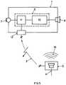
- Fig. 1shows a top view of a hearing device user 2 wearing a hearing device 1 in or at one of his ears in an exemplary aspect which does not form part of the invention as claimed.
- the present inventionis explained in connection with a monaural hearing device, the present invention can also very well be used in connection with a binaural hearing device. In fact, and as a result of the above-mentioned definition of the term "hearing device", the present invention can also very well be used in connection with any type of communication device.
- Fig. 1shows a sound source S that is located at a distance d from the hearing device 1 or the hearing device user 2, respectively.
- the sound source Smay be of any type, in particular it may be one of the following devices:
- the sound source Sis able to broadcast an audio signal 4 as an acoustic signal 13.
- the audio signal 4is comprised in a transmission signal 3 that is transmitted by a transmitter unit comprised in the audio source S.
- the transmitter unitmay also be attached to the audio source S.
- the transmission signal 3may be distributed by wire or wirelessly. In particular, the transmission signal 3 is distributed in one or more than one of the following manners:
- the hearing device 1comprises an input transducer (not shown in Fig. 1 ), e.g. a microphone, the acoustic audio signal 13 of the sound source S is picked up by the input transducer and processed by the hearing device 1.
- the hearing device 1comprises means for searching for a transmission signal 3 of the sound source S, the transmission signal 3 being an electric or electromagnetic signal comprising the audio signal 4.
- the audio signal 4can be modulated in any form (e.g. frequency or amplitude modulated) or placed in any protocol in order to easily transmit the audio signal 4 to the hearing device 1.
- the audio signal 4is available in two forms in the hearing device 1, namely as a clear and undisturbed audio signal directly from the audio source S via the transmission signal 3, and as an output signal of the input transducer of the hearing device 1, the output signal comprising the acoustic audio signal 13 as well as any possible surrounding sound and/or noise.
- a distance d between the sound source S and the hearing device 1is determined. This can be achieved in one of the following manners:
- the distance dis compared to a predetermined distance which is set beforehand.
- the predetermined distanceis a threshold below which the audio signal of the transmission signal 3 is at least partly supplied to an output transducer (not shown in Fig. 1 ) of the hearing device 1.
- the predetermined distanceis set to a value in dependence on an actual situation. For example, if the audio source S is a TV set, the predetermined distance must not be overly larger than a distance between the TV set and the sofa the hearing device user usually sits on when watching TV.
- the hearing device user 2only hears the audio signal 4 coming directly from the sound source S via the transmission signal 3. There is absolutely no disturbing sound of the surrounding.
- the output signal of the input transducer of the hearing device 1is not fully attenuated. Instead, the output signal of the input transducer is only attenuated to an extent that other acoustic sources can still be heard. Therewith, the hearing device user 2 is not completely isolated and can still communicate with other individuals. Most importantly, the hearing device user 2 can hear possible alarm signals, like a fire alarm.
- a supply of the audio signal 4 of the transmission signal 3 to the hearing device user 2does not make sense if the distance d between the hearing device user 2 and the sound source S is too big. For example, a TV set in a large room might only become important if the hearing device user 2 is within a range in that he can clearly see what is shown on the screen of the TV set. This can be taken into account when determining the predetermined distance.
- Fig. 2shows an embodiment of the present invention.
- the same situationis depicted as in Fig. 1 , namely a hearing device user 2 wearing a hearing device 1 as well as a sound source S. It is pointed out that the same reference sign as in Fig. 1 are used in Fig. 2 .
- an angle ⁇is determined that is defined by a sagittal plane 5 of the hearing device user 2 and a line drawn between the hearing device 1 and the sound source S. Once the angle ⁇ is obtained, it is used to determine how much of the audio signal 4 of the transmission signal 3 is supplied to the output transducer of the hearing device 1.
- the extent of supplying the audio signal 4 of the transmission signal 3 to the output transduceris governed by a function of the angle ⁇ .
- An example for such a functionis the trigonometric function cosine: If the hearing device user 2 is facing the sound source S, for which ⁇ is equal to 0°, the audio signal 4 of the transmission signal 3 has a large influence on the input signal of the output transducer (not shown in Fig. 2 ). On the other hand, if the hearing device user 2 is turning his head to the side, for example towards another person, the influence of the audio signal 4 of the transmission signal 3 on the output transducer of the hearing device 1 is reduced or eventually eliminated. Therewith, the possibility is opened up to allow the hearing device user 2 to communicate with other individuals without being too much disturbed by the audio signal 4 of the transmission signal 3.
- the angle ⁇can be determined in one of the following ways:
- Fig. 3shows an exemplary aspect which does not form part of the invention as claimed. Again, a similar situation is depicted as in Figs. 1 and 2 .
- the exemplary aspect of Fig. 3represents a combination of the exemplary aspect and inventive embodiment depicted in Figs. 1 and 2 in that the distance d between the sound source S and the hearing device 1 as well as the angle ⁇ defined by the sagittal plane 5 of the hearing device user 2 and the line drawn between the hearing device 1 and the sound source S are taken into account while determining the influence of the audio signal 4 of the transmission signal 3 on the output transducer of the hearing device 1.
- the distance d and the angle ⁇have effect on the input signal of the output transducer in the hearing device 1 can be determined in the same or similar manners as have been explained in connection with the exemplary aspect and embodiment of Figs. 1 and 2 .
- the sound source Sis a so called virtual sound source in that it does not physically exist but only virtually.
- the location - and therewith the distance d and the angle ⁇ , respectively -is defined virtually and it is assumed that the transmission signal 3 is transmitted from this location.
- the transmission signal 3 comprising the audio signal 4can be transmitted from any location.
- the sound source Sis represented in dashed lines and why there is not shown the acoustic audio signal 13 as in Figs. 1 and 2 .
- this exemplary aspecthas the same characteristics or combination of characteristics as the exemplary aspect and embodiment explained in connection with Fig. 1 and 2 , with the exception that the sound source S does not physically exist.
- FIG. 4yet a further embodiment of the present invention is depicted.
- the hearing device user 2 wearing a hearing device 1 as well as the sound source Sis represented. Accordingly, the explanations made in connection with the aspects and embodiment depicted in Fig. 1 to 3 are also valid.
- Fig. 4additionally shows an obstacle 6 between the hearing device user 2 and the sound source S, be it physically present or be it virtually only, and a radiation angle ⁇ that is defined between a radiation direction of the acoustic audio signal 13 of the sound source S and a line drawn between the hearing device 1 and the sound source S.
- the radiation angle ⁇is used, in one embodiment, to damp the audio signal 4 of the transmission signal 3, i.e.
- the influence on the input signal of the output transducer of the hearing device 1is dependent on the radiation angle ⁇ , in particular the influence on the input signal of the output transducer of the hearing device 1 is a function of the radiation angle ⁇ .
- Thisis very useful in a situation, for example, where the hearing device user 2 positions himself behind the sound source S.
- a clear damping of the audio signal 4 of the transmission signal 3will be welcomed by the hearing device user 2, because one can assume that the hearing device user 2 is not interested in the audio signal of the TV set without being able to see the image on the screen of the TV set.
- the output signal - that is supplied to the output transducer 8 ( Fig. 5 ) of the hearing device 1 -is generated by combining the audio signal 4 of the transmission signal 3 and the acoustic signal of the input transducer 7.
- the combination or mixing of the two signalsis done according to a combination ratio that is determined as a function of at least one of the following parameters:
- the acoustic signal of the input transducer 7is attenuated to a large extent.
- most of the audio signal 4 of the transmission signal 3is fed towards the output transducer 8 of the hearing device 1 in order that the hearing device user may very well hear what is broadcasted by the sound source S.
- the combination ratiochanges in that more signal of the input transducer 7 can be perceived allowing the hearing device user to listen to the surrounding.
- the audio signal 4 of the transmission signal 3is reduced at the same time (according to the combination ratio) in order that the hearing device user is not disturbed too much.
- the hearing device usermay still hear the acoustic audio signal (as long as the sound source S is not a virtual sound source as in some aspects).
- This embodimenthas the advantage that the hearing device user may still hear when someone starts a communication.
- the output signal - that is supplied to the output transducer 8 ( Fig. 5 ) of the hearing device 1 -is generated by reducing, according to a reduction rate, signal components of the audio signal 4 of the sound source S contained in the acoustic signal of the input transducer 7 by using the audio signal 4 of the transmission signal 3.
- the reduction rateis determined as a function of at least one of the following parameters:
- the reduction of the audio signal in the acoustic surroundingis obtained, for example, by known estimation algorithms that are used to estimate components of the audio signal that is present in the acoustic surrounding.
- the estimationis performed taking into account knowledge of the undisturbed audio signal received via the transmission signal.
- Fig. 5shows a block diagram of the hearing device 1 and the sound source S to further explain the present invention, in particular in its aspects and embodiments depicted in Fig. 1 to 4 .
- the hearing device 1comprises an input transducer 7, e.g. a microphone, a processing unit 9, an output transducer 8, also called loudspeaker or receiver, and an interface unit 12.
- the input transducer 7, the output transducer 8 as well as the interface unit 12are connected to the processing unit 9 that comprises a pre-processing unit 11 and a post-processing unit 10.
- the interface unit 12is able to search for and receive a transmission signal 3 transmitted by the sound source S.
- the transmission signal 3comprises an audio signal 4 that is also broadcasted by a loudspeaker as an acoustic audio signal 13 if the sound source S is not a virtual sound source S as exemplarily explained in connection with Fig. 3 .
- the audio signal 4 comprised in the transmission signal 3is fed to the processing unit 9 in which the audio signal 4 is processed in the sense explained above, e.g. amplified/attenuated as a function of at least one of the distance d, the angle ⁇ and the radiation angle ⁇ .
- the distance d and/or the angle ⁇ and/or the radiation angle ⁇may be determined in the hearing device 1, i.e. in the processing unit 9, or outside the hearing device 1, e.g. in an accessory device (not shown in Fig. 5 ).
- the transmission signal 3may be distributed by wire or wirelessly between the sound source S and the interface unit 12.
- the transmission signal 3is distributed in one or more than one of the following manners:
Landscapes
- Engineering & Computer Science (AREA)
- Health & Medical Sciences (AREA)
- General Health & Medical Sciences (AREA)
- Neurosurgery (AREA)
- Otolaryngology (AREA)
- Physics & Mathematics (AREA)
- Acoustics & Sound (AREA)
- Signal Processing (AREA)
- Computer Networks & Wireless Communication (AREA)
- Circuit For Audible Band Transducer (AREA)
- Stereophonic System (AREA)
Description
- The present invention is related to methods for operating a hearing device that is worn by a hearing device user as well as to hearing devices.
- Numerous types of hearing devices are known and have been developed to assist individuals with hearing loss. Examples of hearing device types currently available include behind the ear (BTE), in the ear (ITE), in the canal (ITC) and completely in the canal (CIC) hearing devices. In many situations, however, hearing impaired individuals may require a hearing solution beyond that which can be provided by such a hearing device alone. For example, hearing impaired individuals often have great difficulty to follow a normal conversation in noisy environments, encountered at parties, meetings, sporting events or the like, involving a high level of background noise. In addition, hearing impaired individuals often also have difficulties listening to audio sources located at a distance from the individual, or to several audio sources located at various distances from the individual and at various positions relative to the individual.
- A known hearing aid system comprising a secondary source for audio has been described in
US-6 694 034 B2 . The known hearing aid system comprises a directional microphone worn or otherwise supported by a person speaking or by the hearing aid user, as well as detection and switch circuitry to select which of the primary and secondary audio sources should be directed to the hearing aid circuitry. In operation, the detection and switch circuitry receives a signal transmission (preferably wireless) from the secondary audio source and determines whether the signal received is desirable. If the signal transmission is desirable, the circuitry selects that signal for coupling with the hearing aid circuitry. If the transmission signal is not desirable, the circuitry selects the signals from the primary audio source for coupling with the hearing aid circuitry. The criterion for selecting the signal of the secondary audio source is based on the signal strength. If the incoming signal of the secondary audio source is greater than a predetermined threshold, the signal of the secondary audio source is selected for transmission into the ear canal of the hearing aid wearer. - Similar techniques as the one described above are disclosed by
US-7 317 805 B2 andEP-1 296 537 A2 . - Document
WO 2008/071807 A2 discloses a hearing device with a receiver for receiving a transmission signal of a mobile telephone. The transmission signal is used as input signal to the hearing device if a distance between the hearing device and the mobile telephone is below a predefined distance to ensure that the hearing device user is actually using the mobile telephone. - Document
WO 2008/006772 A2 refers to a binaural hearing system comprising two hearing devices that are interconnected via a wireless link. The wireless link is used to transmit an audio signal picked up by the respective microphone in order to calculate the angle of incidence of a sound signal. - Document
WO 99/31938 A1 - Document
WO 2009/049645 A1 relates to a method for providing hearing assistance to a user. The method comprises capturing audio signals by an internal microphone arrangement and supplying the captured audio signals to a central signal processing unit. Document EP 1 879 426 A2 discloses an apparatus for a binaural hearing assistance system using a monaural audio signal input. The system provides adjustable delay/phase adjustment and sound level adjustment.- The known teachings are only directed to detecting sound sources or they try to qualify sound sources. Natural behavior of a hearing device user is not taken into account.
- Many objects, aspects and variations of the present invention will become apparent to one of skill in the art upon review of the prior art and in light of the teachings herein.
- These and other problems experienced by hearing device users are addressed by the methods and the hearing devices of the present invention.
- It is pointed out that the term "hearing device" must not only be understood as a device that is used to improve the hearing of hearing impaired patients, but also as a communication device to improve communication between individuals. In addition, the term "hearing device" comprise hearing device types currently available, as for example behind the ear (BTE), in the ear (ITE), in the canal (ITC) and completely in the canal (CIC) hearing devices. Furthermore, hearing devices may also be fully or partially implantable.
- First, the present invention is directed to a method for operating a hearing device that is worn by a hearing device user, the method comprising the steps of:
- receiving an acoustic signal by an input transducer of the hearing device, the acoustic signal comprising an audio signal of a sound source;
- receiving a transmission signal comprising said audio signal of said sound sources,
- determining an angle defined by a sagittal plane of the hearing device user and a line drawn between the hearing device and the sound source, and
- generating an output signal supplied to an output transducer of the hearing device by combining the audio signal of the transmission signal and the acoustic signal of the input transducer according to a combination ratio that is determined as a function of at least the angle.
- Embodiments of the present invention further comprise the steps of:
- determining a distance between the sound source and the hearing device,
- generating the output signal supplied to the output transducer of the hearing device by further taking into account the distance.
- In further embodiments of the present invention, the step of generating the output signal supplied to the output transducer of the hearing device further takes into account a radiation angle that is defined by an angle between a radiation direction of sound of the sound source and a line drawn between the hearing device and the sound source.
- In embodiments of the present invention the combination ratio is further determined as a function of at least one of a distance between the sound source and the hearing device, and a radiation angle defined by an angle between a radiation direction of sound of the sound source and a line drawn between the hearing device and the sound source.
- In still further embodiments of the present invention, the transmission signal is wirelessly transmitted to the hearing device.
- Further embodiments of the present invention comprise the step of adjusting the distance in dependence of a size of an obstacle between the hearing device and the sound source by virtually increasing the actual distance to a larger virtual distance, the virtual distance becoming effective for any computation involving said distance.
- In still further embodiments of the present invention, the step of receiving the transmission signal comprising the audio signal of the sound source is performed in the hearing device.
- The present invention is further directed to a hearing device comprising:
- an input transducer for receiving an acoustic signal comprising an audio signal of a sound source,
- an interface unit for receiving a transmission signal comprising said audio signal of said sound source, wherein the interface unit is operatively connected to the processing unit (9),
- an output transducer,
- a processing unit operatively connected to the input transducer as well as to the output transducer,
- means for determining an angle defined by a sagittal plane of a hearing device user and a line drawn between the hearing device and the sound source, and
- means for generating an output signal supplied to the output transducer of the hearing device by combining the audio signal of the transmission signal and the acoustic signal of the input transducer according to a combination ratio that is determined as a function of at least the angle.
- An embodiment of the inventive hearing device further comprises:
- means for determining a distance of the hearing device to the sound source,
- means for generating the output signal supplied to the output transducer by further taking into account the distance.
- In an embodiment of the hearing device the interface unit is a wireless interface unit that is operatively connectable to a wireless unit of the sound source.
- Fig. 1
- schematically shows an arrangement comprising a hearing device user with inserted hearing devices and a sound source for illustration of an exemplary aspect of the present invention,
- Fig. 2
- schematically shows an arrangement comprising the hearing device user with inserted hearing devices and the sound source for illustration of the present invention,
- Fig. 3
- schematically shows an arrangement comprising the hearing device user with inserted hearing devices and the sound source for illustration of an exemplary aspect of the present invention,
- Fig. 4
- schematically shows an arrangement comprising the hearing device user with inserted hearing devices and the sound source for illustration of an embodiment of the present invention, and
- Fig. 5
- shows a block diagram of a hearing device as well as a sound source.
Fig. 1 shows a top view of ahearing device user 2 wearing ahearing device 1 in or at one of his ears in an exemplary aspect which does not form part of the invention as claimed. Although the present invention is explained in connection with a monaural hearing device, the present invention can also very well be used in connection with a binaural hearing device. In fact, and as a result of the above-mentioned definition of the term "hearing device", the present invention can also very well be used in connection with any type of communication device.- Furthermore, in the exemplary aspect,
Fig. 1 shows a sound source S that is located at a distance d from thehearing device 1 or thehearing device user 2, respectively. The sound source S may be of any type, in particular it may be one of the following devices: - TV device;
- screen, e.g. in a movie theater;
- teller at a bank, post office, railway station, or the like;
- lectern;
- pulpit microphone;
- remote microphone;
- hi-fi system.
- The sound source S is able to broadcast an
audio signal 4 as anacoustic signal 13. At the same time, theaudio signal 4 is comprised in atransmission signal 3 that is transmitted by a transmitter unit comprised in the audio source S. The transmitter unit may also be attached to the audio source S. Thetransmission signal 3 may be distributed by wire or wirelessly. In particular, thetransmission signal 3 is distributed in one or more than one of the following manners: - cable, e.g. Ethernet cable;
- infrared;
- Bluetooth standard;
- Wireless Local Area Network (WLAN);
- Global System Mobile (GSM), or any other standard, e.g. UMTS.
- Since the
hearing device 1 comprises an input transducer (not shown inFig. 1 ), e.g. a microphone, theacoustic audio signal 13 of the sound source S is picked up by the input transducer and processed by thehearing device 1. In addition, thehearing device 1 comprises means for searching for atransmission signal 3 of the sound source S, thetransmission signal 3 being an electric or electromagnetic signal comprising theaudio signal 4. It is pointed out that theaudio signal 4 can be modulated in any form (e.g. frequency or amplitude modulated) or placed in any protocol in order to easily transmit theaudio signal 4 to thehearing device 1. In fact, theaudio signal 4 is available in two forms in thehearing device 1, namely as a clear and undisturbed audio signal directly from the audio source S via thetransmission signal 3, and as an output signal of the input transducer of thehearing device 1, the output signal comprising theacoustic audio signal 13 as well as any possible surrounding sound and/or noise. - In the exemplary aspect, a distance d between the sound source S and the
hearing device 1 is determined. This can be achieved in one of the following manners: - the position of the hearing device is fix and known;
- GPS-(Global Positioning System) or similar positioning method is used;
- position is transmitted via a protocol; for example, the position is incorporated into the transmission signal;
- calculation of the relative position via differentiation;
- by determination of moving direction and with an acceleration sensor;
- with the aid of acoustic localization of the audio source S in the
hearing device 1 by comparing the audio signal obtained by the input transducer and the audio signal incorporated into thetransmission signal 3; - distance measurement by signal propagation delay.
- The distance d is compared to a predetermined distance which is set beforehand. The predetermined distance is a threshold below which the audio signal of the
transmission signal 3 is at least partly supplied to an output transducer (not shown inFig. 1 ) of thehearing device 1. The predetermined distance is set to a value in dependence on an actual situation. For example, if the audio source S is a TV set, the predetermined distance must not be overly larger than a distance between the TV set and the sofa the hearing device user usually sits on when watching TV. - With regard to the extent of supplying the
audio signal 4 of thetransmission signal 3 to the output transducer, i.e. the hearer or loudspeaker of thehearing device 1, it is pointed out that it can mean to fully supply theaudio signal 4 of thetransmission signal 3 to the output transducer without containing any part of the output signal of the input transducer of thehearing device 1. In other words, thehearing device user 2 only hears theaudio signal 4 coming directly from the sound source S via thetransmission signal 3. There is absolutely no disturbing sound of the surrounding. - While a full attenuation of the output signal of the input transducer results in a clear and undisturbed signal for the output transducer, and therewith in a high comfort level for the
hearing device user 2, communication with other individuals becomes more difficult. In further embodiments or aspects, it is therefore suggested that the output signal of the input transducer of thehearing device 1 is not fully attenuated. Instead, the output signal of the input transducer is only attenuated to an extent that other acoustic sources can still be heard. Therewith, thehearing device user 2 is not completely isolated and can still communicate with other individuals. Most importantly, thehearing device user 2 can hear possible alarm signals, like a fire alarm. - A supply of the
audio signal 4 of thetransmission signal 3 to thehearing device user 2 does not make sense if the distance d between thehearing device user 2 and the sound source S is too big. For example, a TV set in a large room might only become important if thehearing device user 2 is within a range in that he can clearly see what is shown on the screen of the TV set. This can be taken into account when determining the predetermined distance. Fig. 2 shows an embodiment of the present invention. The same situation is depicted as inFig. 1 , namely ahearing device user 2 wearing ahearing device 1 as well as a sound source S. It is pointed out that the same reference sign as inFig. 1 are used inFig. 2 . Instead of determining a distance d as it has been done in connection with the situation depicted inFig. 1 , an angle α is determined that is defined by asagittal plane 5 of thehearing device user 2 and a line drawn between thehearing device 1 and the sound source S. Once the angle α is obtained, it is used to determine how much of theaudio signal 4 of thetransmission signal 3 is supplied to the output transducer of thehearing device 1. The extent of supplying theaudio signal 4 of thetransmission signal 3 to the output transducer is governed by a function of the angle α. An example for such a function is the trigonometric function cosine: If thehearing device user 2 is facing the sound source S, for which α is equal to 0°, theaudio signal 4 of thetransmission signal 3 has a large influence on the input signal of the output transducer (not shown inFig. 2 ). On the other hand, if thehearing device user 2 is turning his head to the side, for example towards another person, the influence of theaudio signal 4 of thetransmission signal 3 on the output transducer of thehearing device 1 is reduced or eventually eliminated. Therewith, the possibility is opened up to allow thehearing device user 2 to communicate with other individuals without being too much disturbed by theaudio signal 4 of thetransmission signal 3.- For example, the angle α can be determined in one of the following ways:
- the orientation of the hearing device is known;
- electronic compass is integrated into the hearing device while the sound source S is known;
- GPS-(Global Positioning System) or a similar orientation measurement method is used;
- orientation is transmitted via a protocol;
- calculation of the relative orientation via differentiation;
- by determination of moving direction and with a acceleration sensor;
- with the aid of acoustic localization of the sound source S in the
hearing device 1 by comparing theaudio signal 4 obtained by the input transducer and the audio signal incorporated into thetransmission signal 3; - radar like, e.g. transponder.
Fig. 3 shows an exemplary aspect which does not form part of the invention as claimed. Again, a similar situation is depicted as inFigs. 1 and 2 . In fact, the exemplary aspect ofFig. 3 represents a combination of the exemplary aspect and inventive embodiment depicted inFigs. 1 and 2 in that the distance d between the sound source S and thehearing device 1 as well as the angle α defined by thesagittal plane 5 of thehearing device user 2 and the line drawn between thehearing device 1 and the sound source S are taken into account while determining the influence of theaudio signal 4 of thetransmission signal 3 on the output transducer of thehearing device 1. To what extent the distance d and the angle α have effect on the input signal of the output transducer in thehearing device 1 can be determined in the same or similar manners as have been explained in connection with the exemplary aspect and embodiment ofFigs. 1 and 2 .- A still further exemplary aspect is pointed out while referring to
Fig. 3 : the sound source S is a so called virtual sound source in that it does not physically exist but only virtually. The location - and therewith the distance d and the angle α, respectively - is defined virtually and it is assumed that thetransmission signal 3 is transmitted from this location. In fact, thetransmission signal 3 comprising theaudio signal 4 can be transmitted from any location. This is why the sound source S is represented in dashed lines and why there is not shown theacoustic audio signal 13 as inFigs. 1 and 2 . Apart from this virtual arrangement, this exemplary aspect has the same characteristics or combination of characteristics as the exemplary aspect and embodiment explained in connection withFig. 1 and 2 , with the exception that the sound source S does not physically exist. - In
Fig. 4 , yet a further embodiment of the present invention is depicted. As inFigs. 1 to 3 , thehearing device user 2 wearing ahearing device 1 as well as the sound source S is represented. Accordingly, the explanations made in connection with the aspects and embodiment depicted inFig. 1 to 3 are also valid.Fig. 4 additionally shows anobstacle 6 between thehearing device user 2 and the sound source S, be it physically present or be it virtually only, and a radiation angle β that is defined between a radiation direction of theacoustic audio signal 13 of the sound source S and a line drawn between thehearing device 1 and the sound source S. The radiation angle β is used, in one embodiment, to damp theaudio signal 4 of thetransmission signal 3, i.e. the influence on the input signal of the output transducer of thehearing device 1 is dependent on the radiation angle β, in particular the influence on the input signal of the output transducer of thehearing device 1 is a function of the radiation angle β. This is very useful in a situation, for example, where thehearing device user 2 positions himself behind the sound source S. In particular for a TV set as sound source S, a clear damping of theaudio signal 4 of thetransmission signal 3 will be welcomed by thehearing device user 2, because one can assume that thehearing device user 2 is not interested in the audio signal of the TV set without being able to see the image on the screen of the TV set. - Similar situations are obtained if an
obstacle 6 between thehearing device user 2 and the sound source S is present. In dependence on the size of theobstacle 6, theaudio signal 4 transmitted by thetransmission signal 3 is reduced before it is fed to the input of the output transducer of thehearing device 1. This can also be interpreted by virtually increasing the actual distance d to a larger virtual distance d', the virtual distance d' becoming effective for any computation involving the distance d, in particular the computations explained in connection with the aspects and embodiment depicted inFigs. 1 to 3 . - In a further embodiment of the present invention, the output signal - that is supplied to the output transducer 8 (
Fig. 5 ) of the hearing device 1 - is generated by combining theaudio signal 4 of thetransmission signal 3 and the acoustic signal of the input transducer 7. The combination or mixing of the two signals is done according to a combination ratio that is determined as a function of at least one of the following parameters: - the distance d;
- the angle α;
- the radiation angle β.
- As long as the hearing device user sits in front of the sound source S, while having turned his head towards the sound source S, the acoustic signal of the input transducer 7 is attenuated to a large extent. At the same time, most of the
audio signal 4 of thetransmission signal 3 is fed towards theoutput transducer 8 of thehearing device 1 in order that the hearing device user may very well hear what is broadcasted by the sound source S. As soon as the hearing device user turns his head away from the sound source S, thereby increasing the angle α, the combination ratio changes in that more signal of the input transducer 7 can be perceived allowing the hearing device user to listen to the surrounding. To improve the ability to listen to surroundings signals, theaudio signal 4 of thetransmission signal 3 is reduced at the same time (according to the combination ratio) in order that the hearing device user is not disturbed too much. Of course, the hearing device user may still hear the acoustic audio signal (as long as the sound source S is not a virtual sound source as in some aspects). This embodiment has the advantage that the hearing device user may still hear when someone starts a communication. - In a still further embodiment of the present invention, the output signal - that is supplied to the output transducer 8 (
Fig. 5 ) of the hearing device 1 - is generated by reducing, according to a reduction rate, signal components of theaudio signal 4 of the sound source S contained in the acoustic signal of the input transducer 7 by using theaudio signal 4 of thetransmission signal 3. The reduction rate is determined as a function of at least one of the following parameters: - the distance d;
- the angle α;
- the radiation angle β.
- The reduction of the audio signal in the acoustic surrounding is obtained, for example, by known estimation algorithms that are used to estimate components of the audio signal that is present in the acoustic surrounding. The estimation is performed taking into account knowledge of the undisturbed audio signal received via the transmission signal.
Fig. 5 shows a block diagram of thehearing device 1 and the sound source S to further explain the present invention, in particular in its aspects and embodiments depicted inFig. 1 to 4 .- The
hearing device 1 comprises an input transducer 7, e.g. a microphone, a processing unit 9, anoutput transducer 8, also called loudspeaker or receiver, and aninterface unit 12. The input transducer 7, theoutput transducer 8 as well as theinterface unit 12 are connected to the processing unit 9 that comprises apre-processing unit 11 and apost-processing unit 10. Theinterface unit 12 is able to search for and receive atransmission signal 3 transmitted by the sound source S. Thetransmission signal 3 comprises anaudio signal 4 that is also broadcasted by a loudspeaker as anacoustic audio signal 13 if the sound source S is not a virtual sound source S as exemplarily explained in connection withFig. 3 . Theaudio signal 4 comprised in thetransmission signal 3 is fed to the processing unit 9 in which theaudio signal 4 is processed in the sense explained above, e.g. amplified/attenuated as a function of at least one of the distance d, the angle α and the radiation angle β. Thereby, the distance d and/or the angle α and/or the radiation angle β may be determined in thehearing device 1, i.e. in the processing unit 9, or outside thehearing device 1, e.g. in an accessory device (not shown inFig. 5 ). - The
transmission signal 3 may be distributed by wire or wirelessly between the sound source S and theinterface unit 12. In particular, thetransmission signal 3 is distributed in one or more than one of the following manners: - cable, e.g. Ethernet cable, standard audio cable or USB cable;
- infrared;
- Bluetooth standard;
- Wireless Local Area Network (WLAN);
- Global System Mobile (GSM), or any other standard, e.g. UMTS.
- It is to be understood that the above-described embodiments are merely illustrations of the present invention and that many variations of the above-described embodiments can be devised by those skilled in the art without departing from the scope of the invention as defined by the appended claims.
Claims (10)
- A method for operating a hearing device (1) that is worn by a hearing device user (2), the method comprising the steps of:- receiving an acoustic signal (13) by an input transducer (7) of the hearing device (1), the acoustic signal (13) comprising an audio signal (4) of a sound source (S);- receiving a transmission signal (3) comprising said audio signal (4) of said sound source (S),said method further comprising:- determining an angle (α) defined by a sagittal plane (5) of the hearing device user (2) and a line drawn between the hearing device (1) and the sound source (S), and- generating an output signal supplied to an output transducer (8) of the hearing device (1) by combining the audio signal (4) of the transmission signal (3) and the acoustic signal (13) of the input transducer (7) according to a combination ratio that is determined as a function of at least the angle (α).
- The method of claim 1, further comprising the steps of:- determining a distance (d) between the sound source (S) and the hearing device (1), and- generating the output signal supplied to the output transducer (8) of the hearing device (1) by further taking into account the distance (d).
- The method of one of the claims 1 to 2, wherein the step of generating the output signal supplied to the output transducer (8) of the hearing device (1) further takes into account a radiation angle (β) that is defined by an angle between a radiation direction of sound of the sound source (S) and a line drawn between the hearing device (1) and the sound source (S).
- The method of one of the claims 1 to 3, wherein- the combination ratio is further determined as a function of at least one of a distance (d) between the sound source (S) and the hearing device (1), and a radiation angle (β) defined by an angle between a radiation direction of sound of the sound source (S) and a line drawn between the hearing device (1) and the sound source (S).
- The method of one of the claims 1 to 4, wherein the transmission signal (3) is wirelessly transmitted to the hearing device (1).
- The method of one of the claims 2 to 5, further comprising the step of adjusting the distance (d) in dependence of a size of an obstacle (6) between the hearing device (1) and the sound source (S) by virtually increasing the actual distance (d) to a larger virtual distance (d'), the virtual distance (d') becoming effective for any computation involving said distance (d).
- The method of one of the claims 1 to 5, wherein the step of receiving the transmission signal (3) comprising the audio signal (4) of the sound source (S) is performed in the hearing device (1).
- A hearing device (1) comprising:- an input transducer (7) for receiving an acoustic signal (13) comprising an audio signal (4) of a sound source (S),- an interface unit (12) for receiving a transmission signal (3) comprising said audio signal (4) of said sound source (S), wherein the interface unit (12) is operatively connected to the processing unit (9),- an output transducer (8),- a processing unit (9) operatively connected to the input transducer (7) as well as to the output transducer (8),- means for determining an angle (α) defined by a sagittal plane (5) of a hearing device user (2) and a line drawn between the hearing device (1) and the sound source (S), and- means for generating an output signal supplied to the output transducer (8) of the hearing device (1) by combining the audio signal (4) of the transmission signal (3) and the acoustic signal (13) of the input transducer (7) according to a combination ratio that is determined as a function of at least the angle (α).
- The hearing device of claim 8, further comprising:- means for determining a distance (d) of the hearing device to the sound source (S),- means for generating the output signal supplied to the output transducer (8) of the hearing device (1) by further taking into account the distance (d).
- The hearing device of one of the claims 8 to 9, wherein the interface unit (12) is a wireless interface unit that is operatively connectable to a wireless unit of the sound source (S).
Applications Claiming Priority (1)
| Application Number | Priority Date | Filing Date | Title |
|---|---|---|---|
| PCT/EP2010/056032WO2010086462A2 (en) | 2010-05-04 | 2010-05-04 | Methods for operating a hearing device as well as hearing devices |
Publications (2)
| Publication Number | Publication Date |
|---|---|
| EP2567551A2 EP2567551A2 (en) | 2013-03-13 |
| EP2567551B1true EP2567551B1 (en) | 2018-07-11 |
Family
ID=42357630
Family Applications (1)
| Application Number | Title | Priority Date | Filing Date |
|---|---|---|---|
| EP10716548.2AActiveEP2567551B1 (en) | 2010-05-04 | 2010-05-04 | Methods for operating a hearing device as well as hearing devices |
Country Status (3)
| Country | Link |
|---|---|
| US (1) | US9344813B2 (en) |
| EP (1) | EP2567551B1 (en) |
| WO (1) | WO2010086462A2 (en) |
Families Citing this family (16)
| Publication number | Priority date | Publication date | Assignee | Title |
|---|---|---|---|---|
| CN103053181A (en)* | 2011-03-08 | 2013-04-17 | 松下电器产业株式会社 | Audio control device and audio control method |
| EP2528358A1 (en)* | 2011-05-23 | 2012-11-28 | Oticon A/S | A method of identifying a wireless communication channel in a sound system |
| US20120321112A1 (en)* | 2011-06-16 | 2012-12-20 | Apple Inc. | Selecting a digital stream based on an audio sample |
| EP2560161A1 (en) | 2011-08-17 | 2013-02-20 | Fraunhofer-Gesellschaft zur Förderung der angewandten Forschung e.V. | Optimal mixing matrices and usage of decorrelators in spatial audio processing |
| EP2584794A1 (en)* | 2011-10-17 | 2013-04-24 | Oticon A/S | A listening system adapted for real-time communication providing spatial information in an audio stream |
| US9451370B2 (en) | 2012-03-12 | 2016-09-20 | Sonova Ag | Method for operating a hearing device as well as a hearing device |
| US9338561B2 (en) | 2012-12-28 | 2016-05-10 | Gn Resound A/S | Hearing aid with improved localization |
| US9148733B2 (en) | 2012-12-28 | 2015-09-29 | Gn Resound A/S | Hearing aid with improved localization |
| US9148735B2 (en) | 2012-12-28 | 2015-09-29 | Gn Resound A/S | Hearing aid with improved localization |
| US9100762B2 (en) | 2013-05-22 | 2015-08-04 | Gn Resound A/S | Hearing aid with improved localization |
| US9124983B2 (en) | 2013-06-26 | 2015-09-01 | Starkey Laboratories, Inc. | Method and apparatus for localization of streaming sources in hearing assistance system |
| EP2890161A1 (en)* | 2013-12-30 | 2015-07-01 | GN Store Nord A/S | An assembly and a method for determining a distance between two sound generating objects |
| DK3111672T3 (en) | 2014-02-24 | 2018-01-02 | Widex As | HEARING WITH SUPPORTED NOISE PRESSURE |
| US9432778B2 (en) | 2014-04-04 | 2016-08-30 | Gn Resound A/S | Hearing aid with improved localization of a monaural signal source |
| EP3381203A1 (en) | 2015-11-24 | 2018-10-03 | Sonova AG | Method of operating a hearing aid and hearing aid operating according to such method |
| US9900735B2 (en) | 2015-12-18 | 2018-02-20 | Federal Signal Corporation | Communication systems |
Citations (1)
| Publication number | Priority date | Publication date | Assignee | Title |
|---|---|---|---|---|
| WO1999031938A1 (en)* | 1997-12-13 | 1999-06-24 | Central Research Laboratories Limited | A method of processing an audio signal |
Family Cites Families (22)
| Publication number | Priority date | Publication date | Assignee | Title |
|---|---|---|---|---|
| US5333153A (en)* | 1992-01-21 | 1994-07-26 | Motorola, Inc. | Signal quality detection method and apparatus for optimum audio muting |
| US5870484A (en)* | 1995-09-05 | 1999-02-09 | Greenberger; Hal | Loudspeaker array with signal dependent radiation pattern |
| JPH11275696A (en)* | 1998-01-22 | 1999-10-08 | Sony Corp | Headphone, headphone adapter, and headphone device |
| US6694034B2 (en)* | 2000-01-07 | 2004-02-17 | Etymotic Research, Inc. | Transmission detection and switch system for hearing improvement applications |
| DE10146886B4 (en) | 2001-09-24 | 2007-11-08 | Siemens Audiologische Technik Gmbh | Hearing aid with automatic switching to Hasp coil operation |
| US7602928B2 (en)* | 2002-07-01 | 2009-10-13 | Avaya Inc. | Telephone with integrated hearing aid |
| JP4254502B2 (en)* | 2003-11-21 | 2009-04-15 | ヤマハ株式会社 | Array speaker device |
| US8116465B2 (en)* | 2004-04-28 | 2012-02-14 | Sony Corporation | Measuring apparatus and method, and recording medium |
| JP2005341384A (en)* | 2004-05-28 | 2005-12-08 | Sony Corp | Sound field correcting apparatus and sound field correcting method |
| US8208642B2 (en)* | 2006-07-10 | 2012-06-26 | Starkey Laboratories, Inc. | Method and apparatus for a binaural hearing assistance system using monaural audio signals |
| US8295497B2 (en) | 2006-07-12 | 2012-10-23 | Phonak Ag | Method for operating a binaural hearing system as well as a binaural hearing system |
| WO2008043731A1 (en)* | 2006-10-10 | 2008-04-17 | Siemens Audiologische Technik Gmbh | Method for operating a hearing aid, and hearing aid |
| US20100195836A1 (en)* | 2007-02-14 | 2010-08-05 | Phonak Ag | Wireless communication system and method |
| DE102007011841C5 (en)* | 2007-03-12 | 2015-05-13 | Siemens Audiologische Technik Gmbh | Transmission method with dynamic transmission power adjustment and corresponding hearing aid system |
| US8350908B2 (en)* | 2007-05-22 | 2013-01-08 | Vidsys, Inc. | Tracking people and objects using multiple live and recorded surveillance camera video feeds |
| KR101427648B1 (en)* | 2007-10-12 | 2014-08-07 | 삼성전자주식회사 | Method and apparatus for removing non-uniform radiation pattern in an array speaker system |
| EP2206362B1 (en)* | 2007-10-16 | 2014-01-08 | Phonak AG | Method and system for wireless hearing assistance |
| WO2009049645A1 (en) | 2007-10-16 | 2009-04-23 | Phonak Ag | Method and system for wireless hearing assistance |
| KR101524463B1 (en)* | 2007-12-04 | 2015-06-01 | 삼성전자주식회사 | And apparatus for focusing sound through array speakers |
| US9071916B2 (en)* | 2008-03-11 | 2015-06-30 | Phonak Ag | Telephone to hearing device communication |
| US20100008515A1 (en)* | 2008-07-10 | 2010-01-14 | David Robert Fulton | Multiple acoustic threat assessment system |
| US8553897B2 (en)* | 2009-06-09 | 2013-10-08 | Dean Robert Gary Anderson | Method and apparatus for directional acoustic fitting of hearing aids |
- 2010
- 2010-05-04WOPCT/EP2010/056032patent/WO2010086462A2/enactiveApplication Filing
- 2010-05-04EPEP10716548.2Apatent/EP2567551B1/enactiveActive
- 2010-05-04USUS13/695,305patent/US9344813B2/enactiveActive
Patent Citations (1)
| Publication number | Priority date | Publication date | Assignee | Title |
|---|---|---|---|---|
| WO1999031938A1 (en)* | 1997-12-13 | 1999-06-24 | Central Research Laboratories Limited | A method of processing an audio signal |
Also Published As
| Publication number | Publication date |
|---|---|
| WO2010086462A2 (en) | 2010-08-05 |
| US20130064403A1 (en) | 2013-03-14 |
| EP2567551A2 (en) | 2013-03-13 |
| US9344813B2 (en) | 2016-05-17 |
| WO2010086462A3 (en) | 2011-02-24 |
Similar Documents
| Publication | Publication Date | Title |
|---|---|---|
| EP2567551B1 (en) | Methods for operating a hearing device as well as hearing devices | |
| US9930456B2 (en) | Method and apparatus for localization of streaming sources in hearing assistance system | |
| CN104185130B (en) | Hearing aid with spatial signal enhancement | |
| EP4040808B1 (en) | Hearing assistance system incorporating directional microphone customization | |
| EP3202160B1 (en) | Method of providing hearing assistance between users in an ad hoc network and corresponding system | |
| US11457308B2 (en) | Microphone device to provide audio with spatial context | |
| US8958587B2 (en) | Signal dereverberation using environment information | |
| EP2840807A1 (en) | External microphone array and hearing aid using it | |
| US11438713B2 (en) | Binaural hearing system with localization of sound sources | |
| US9894446B2 (en) | Customization of adaptive directionality for hearing aids using a portable device | |
| JP6193844B2 (en) | Hearing device with selectable perceptual spatial sound source positioning | |
| US11805364B2 (en) | Hearing device providing virtual sound | |
| US9036845B2 (en) | External input device for a hearing aid | |
| CN109218948B (en) | Hearing aid system, system signal processing unit and method for generating an enhanced electrical audio signal | |
| US11856370B2 (en) | System for audio rendering comprising a binaural hearing device and an external device | |
| EP2809087A1 (en) | An external input device for a hearing aid | |
| CN113556660B (en) | Hearing-aid method and device based on virtual surround sound technology | |
| US20250193610A1 (en) | Method of operating a binaural hearing instrument and binaural hearing instrument | |
| DK201370296A1 (en) | An external input device for a hearing aid |
Legal Events
| Date | Code | Title | Description |
|---|---|---|---|
| PUAI | Public reference made under article 153(3) epc to a published international application that has entered the european phase | Free format text:ORIGINAL CODE: 0009012 | |
| 17P | Request for examination filed | Effective date:20121016 | |
| AK | Designated contracting states | Kind code of ref document:A2 Designated state(s):AL AT BE BG CH CY CZ DE DK EE ES FI FR GB GR HR HU IE IS IT LI LT LU LV MC MK MT NL NO PL PT RO SE SI SK SM TR | |
| DAX | Request for extension of the european patent (deleted) | ||
| 17Q | First examination report despatched | Effective date:20150526 | |
| RAP1 | Party data changed (applicant data changed or rights of an application transferred) | Owner name:SONOVA AG | |
| STAA | Information on the status of an ep patent application or granted ep patent | Free format text:STATUS: EXAMINATION IS IN PROGRESS | |
| GRAP | Despatch of communication of intention to grant a patent | Free format text:ORIGINAL CODE: EPIDOSNIGR1 | |
| STAA | Information on the status of an ep patent application or granted ep patent | Free format text:STATUS: GRANT OF PATENT IS INTENDED | |
| INTG | Intention to grant announced | Effective date:20180126 | |
| GRAS | Grant fee paid | Free format text:ORIGINAL CODE: EPIDOSNIGR3 | |
| GRAA | (expected) grant | Free format text:ORIGINAL CODE: 0009210 | |
| STAA | Information on the status of an ep patent application or granted ep patent | Free format text:STATUS: THE PATENT HAS BEEN GRANTED | |
| AK | Designated contracting states | Kind code of ref document:B1 Designated state(s):AL AT BE BG CH CY CZ DE DK EE ES FI FR GB GR HR HU IE IS IT LI LT LU LV MC MK MT NL NO PL PT RO SE SI SK SM TR | |
| REG | Reference to a national code | Ref country code:GB Ref legal event code:FG4D | |
| REG | Reference to a national code | Ref country code:CH Ref legal event code:EP | |
| REG | Reference to a national code | Ref country code:AT Ref legal event code:REF Ref document number:1018194 Country of ref document:AT Kind code of ref document:T Effective date:20180715 | |
| REG | Reference to a national code | Ref country code:IE Ref legal event code:FG4D | |
| REG | Reference to a national code | Ref country code:DE Ref legal event code:R096 Ref document number:602010051804 Country of ref document:DE | |
| REG | Reference to a national code | Ref country code:NL Ref legal event code:MP Effective date:20180711 | |
| REG | Reference to a national code | Ref country code:LT Ref legal event code:MG4D | |
| REG | Reference to a national code | Ref country code:AT Ref legal event code:MK05 Ref document number:1018194 Country of ref document:AT Kind code of ref document:T Effective date:20180711 | |
| PG25 | Lapsed in a contracting state [announced via postgrant information from national office to epo] | Ref country code:NL Free format text:LAPSE BECAUSE OF FAILURE TO SUBMIT A TRANSLATION OF THE DESCRIPTION OR TO PAY THE FEE WITHIN THE PRESCRIBED TIME-LIMIT Effective date:20180711 | |
| PG25 | Lapsed in a contracting state [announced via postgrant information from national office to epo] | Ref country code:GR Free format text:LAPSE BECAUSE OF FAILURE TO SUBMIT A TRANSLATION OF THE DESCRIPTION OR TO PAY THE FEE WITHIN THE PRESCRIBED TIME-LIMIT Effective date:20181012 Ref country code:NO Free format text:LAPSE BECAUSE OF FAILURE TO SUBMIT A TRANSLATION OF THE DESCRIPTION OR TO PAY THE FEE WITHIN THE PRESCRIBED TIME-LIMIT Effective date:20181011 Ref country code:SE Free format text:LAPSE BECAUSE OF FAILURE TO SUBMIT A TRANSLATION OF THE DESCRIPTION OR TO PAY THE FEE WITHIN THE PRESCRIBED TIME-LIMIT Effective date:20180711 Ref country code:BG Free format text:LAPSE BECAUSE OF FAILURE TO SUBMIT A TRANSLATION OF THE DESCRIPTION OR TO PAY THE FEE WITHIN THE PRESCRIBED TIME-LIMIT Effective date:20181011 Ref country code:AT Free format text:LAPSE BECAUSE OF FAILURE TO SUBMIT A TRANSLATION OF THE DESCRIPTION OR TO PAY THE FEE WITHIN THE PRESCRIBED TIME-LIMIT Effective date:20180711 Ref country code:IS Free format text:LAPSE BECAUSE OF FAILURE TO SUBMIT A TRANSLATION OF THE DESCRIPTION OR TO PAY THE FEE WITHIN THE PRESCRIBED TIME-LIMIT Effective date:20181111 Ref country code:FI Free format text:LAPSE BECAUSE OF FAILURE TO SUBMIT A TRANSLATION OF THE DESCRIPTION OR TO PAY THE FEE WITHIN THE PRESCRIBED TIME-LIMIT Effective date:20180711 Ref country code:PL Free format text:LAPSE BECAUSE OF FAILURE TO SUBMIT A TRANSLATION OF THE DESCRIPTION OR TO PAY THE FEE WITHIN THE PRESCRIBED TIME-LIMIT Effective date:20180711 Ref country code:LT Free format text:LAPSE BECAUSE OF FAILURE TO SUBMIT A TRANSLATION OF THE DESCRIPTION OR TO PAY THE FEE WITHIN THE PRESCRIBED TIME-LIMIT Effective date:20180711 | |
| PG25 | Lapsed in a contracting state [announced via postgrant information from national office to epo] | Ref country code:AL Free format text:LAPSE BECAUSE OF FAILURE TO SUBMIT A TRANSLATION OF THE DESCRIPTION OR TO PAY THE FEE WITHIN THE PRESCRIBED TIME-LIMIT Effective date:20180711 Ref country code:LV Free format text:LAPSE BECAUSE OF FAILURE TO SUBMIT A TRANSLATION OF THE DESCRIPTION OR TO PAY THE FEE WITHIN THE PRESCRIBED TIME-LIMIT Effective date:20180711 Ref country code:HR Free format text:LAPSE BECAUSE OF FAILURE TO SUBMIT A TRANSLATION OF THE DESCRIPTION OR TO PAY THE FEE WITHIN THE PRESCRIBED TIME-LIMIT Effective date:20180711 Ref country code:ES Free format text:LAPSE BECAUSE OF FAILURE TO SUBMIT A TRANSLATION OF THE DESCRIPTION OR TO PAY THE FEE WITHIN THE PRESCRIBED TIME-LIMIT Effective date:20180711 | |
| REG | Reference to a national code | Ref country code:DE Ref legal event code:R097 Ref document number:602010051804 Country of ref document:DE | |
| PG25 | Lapsed in a contracting state [announced via postgrant information from national office to epo] | Ref country code:CZ Free format text:LAPSE BECAUSE OF FAILURE TO SUBMIT A TRANSLATION OF THE DESCRIPTION OR TO PAY THE FEE WITHIN THE PRESCRIBED TIME-LIMIT Effective date:20180711 Ref country code:IT Free format text:LAPSE BECAUSE OF FAILURE TO SUBMIT A TRANSLATION OF THE DESCRIPTION OR TO PAY THE FEE WITHIN THE PRESCRIBED TIME-LIMIT Effective date:20180711 Ref country code:RO Free format text:LAPSE BECAUSE OF FAILURE TO SUBMIT A TRANSLATION OF THE DESCRIPTION OR TO PAY THE FEE WITHIN THE PRESCRIBED TIME-LIMIT Effective date:20180711 Ref country code:EE Free format text:LAPSE BECAUSE OF FAILURE TO SUBMIT A TRANSLATION OF THE DESCRIPTION OR TO PAY THE FEE WITHIN THE PRESCRIBED TIME-LIMIT Effective date:20180711 | |
| PLBE | No opposition filed within time limit | Free format text:ORIGINAL CODE: 0009261 | |
| STAA | Information on the status of an ep patent application or granted ep patent | Free format text:STATUS: NO OPPOSITION FILED WITHIN TIME LIMIT | |
| PG25 | Lapsed in a contracting state [announced via postgrant information from national office to epo] | Ref country code:SK Free format text:LAPSE BECAUSE OF FAILURE TO SUBMIT A TRANSLATION OF THE DESCRIPTION OR TO PAY THE FEE WITHIN THE PRESCRIBED TIME-LIMIT Effective date:20180711 Ref country code:SM Free format text:LAPSE BECAUSE OF FAILURE TO SUBMIT A TRANSLATION OF THE DESCRIPTION OR TO PAY THE FEE WITHIN THE PRESCRIBED TIME-LIMIT Effective date:20180711 Ref country code:DK Free format text:LAPSE BECAUSE OF FAILURE TO SUBMIT A TRANSLATION OF THE DESCRIPTION OR TO PAY THE FEE WITHIN THE PRESCRIBED TIME-LIMIT Effective date:20180711 | |
| 26N | No opposition filed | Effective date:20190412 | |
| PG25 | Lapsed in a contracting state [announced via postgrant information from national office to epo] | Ref country code:SI Free format text:LAPSE BECAUSE OF FAILURE TO SUBMIT A TRANSLATION OF THE DESCRIPTION OR TO PAY THE FEE WITHIN THE PRESCRIBED TIME-LIMIT Effective date:20180711 | |
| REG | Reference to a national code | Ref country code:CH Ref legal event code:PL | |
| PG25 | Lapsed in a contracting state [announced via postgrant information from national office to epo] | Ref country code:CH Free format text:LAPSE BECAUSE OF NON-PAYMENT OF DUE FEES Effective date:20190531 Ref country code:MC Free format text:LAPSE BECAUSE OF FAILURE TO SUBMIT A TRANSLATION OF THE DESCRIPTION OR TO PAY THE FEE WITHIN THE PRESCRIBED TIME-LIMIT Effective date:20180711 Ref country code:LI Free format text:LAPSE BECAUSE OF NON-PAYMENT OF DUE FEES Effective date:20190531 | |
| REG | Reference to a national code | Ref country code:BE Ref legal event code:MM Effective date:20190531 | |
| PG25 | Lapsed in a contracting state [announced via postgrant information from national office to epo] | Ref country code:LU Free format text:LAPSE BECAUSE OF NON-PAYMENT OF DUE FEES Effective date:20190504 | |
| PG25 | Lapsed in a contracting state [announced via postgrant information from national office to epo] | Ref country code:TR Free format text:LAPSE BECAUSE OF FAILURE TO SUBMIT A TRANSLATION OF THE DESCRIPTION OR TO PAY THE FEE WITHIN THE PRESCRIBED TIME-LIMIT Effective date:20180711 | |
| PG25 | Lapsed in a contracting state [announced via postgrant information from national office to epo] | Ref country code:IE Free format text:LAPSE BECAUSE OF NON-PAYMENT OF DUE FEES Effective date:20190504 | |
| PG25 | Lapsed in a contracting state [announced via postgrant information from national office to epo] | Ref country code:BE Free format text:LAPSE BECAUSE OF NON-PAYMENT OF DUE FEES Effective date:20190531 | |
| PG25 | Lapsed in a contracting state [announced via postgrant information from national office to epo] | Ref country code:PT Free format text:LAPSE BECAUSE OF FAILURE TO SUBMIT A TRANSLATION OF THE DESCRIPTION OR TO PAY THE FEE WITHIN THE PRESCRIBED TIME-LIMIT Effective date:20181111 | |
| PG25 | Lapsed in a contracting state [announced via postgrant information from national office to epo] | Ref country code:CY Free format text:LAPSE BECAUSE OF FAILURE TO SUBMIT A TRANSLATION OF THE DESCRIPTION OR TO PAY THE FEE WITHIN THE PRESCRIBED TIME-LIMIT Effective date:20180711 | |
| PG25 | Lapsed in a contracting state [announced via postgrant information from national office to epo] | Ref country code:MT Free format text:LAPSE BECAUSE OF FAILURE TO SUBMIT A TRANSLATION OF THE DESCRIPTION OR TO PAY THE FEE WITHIN THE PRESCRIBED TIME-LIMIT Effective date:20180711 Ref country code:HU Free format text:LAPSE BECAUSE OF FAILURE TO SUBMIT A TRANSLATION OF THE DESCRIPTION OR TO PAY THE FEE WITHIN THE PRESCRIBED TIME-LIMIT; INVALID AB INITIO Effective date:20100504 | |
| PGFP | Annual fee paid to national office [announced via postgrant information from national office to epo] | Ref country code:FR Payment date:20210525 Year of fee payment:12 | |
| PGFP | Annual fee paid to national office [announced via postgrant information from national office to epo] | Ref country code:GB Payment date:20210527 Year of fee payment:12 | |
| PG25 | Lapsed in a contracting state [announced via postgrant information from national office to epo] | Ref country code:MK Free format text:LAPSE BECAUSE OF FAILURE TO SUBMIT A TRANSLATION OF THE DESCRIPTION OR TO PAY THE FEE WITHIN THE PRESCRIBED TIME-LIMIT Effective date:20180711 | |
| GBPC | Gb: european patent ceased through non-payment of renewal fee | Effective date:20220504 | |
| REG | Reference to a national code | Ref country code:DE Ref legal event code:R084 Ref document number:602010051804 Country of ref document:DE | |
| PG25 | Lapsed in a contracting state [announced via postgrant information from national office to epo] | Ref country code:FR Free format text:LAPSE BECAUSE OF NON-PAYMENT OF DUE FEES Effective date:20220531 | |
| PG25 | Lapsed in a contracting state [announced via postgrant information from national office to epo] | Ref country code:GB Free format text:LAPSE BECAUSE OF NON-PAYMENT OF DUE FEES Effective date:20220504 | |
| P01 | Opt-out of the competence of the unified patent court (upc) registered | Effective date:20230530 | |
| PGFP | Annual fee paid to national office [announced via postgrant information from national office to epo] | Ref country code:DE Payment date:20250529 Year of fee payment:16 |