EP2566777B1 - Container for liquids - Google Patents
Container for liquidsDownload PDFInfo
- Publication number
- EP2566777B1 EP2566777B1EP11717245.2AEP11717245AEP2566777B1EP 2566777 B1EP2566777 B1EP 2566777B1EP 11717245 AEP11717245 AEP 11717245AEP 2566777 B1EP2566777 B1EP 2566777B1
- Authority
- EP
- European Patent Office
- Prior art keywords
- container
- casing
- shell
- blow moulded
- excess
- Prior art date
- Legal status (The legal status is an assumption and is not a legal conclusion. Google has not performed a legal analysis and makes no representation as to the accuracy of the status listed.)
- Active
Links
Images


Classifications
- B—PERFORMING OPERATIONS; TRANSPORTING
- B65—CONVEYING; PACKING; STORING; HANDLING THIN OR FILAMENTARY MATERIAL
- B65D—CONTAINERS FOR STORAGE OR TRANSPORT OF ARTICLES OR MATERIALS, e.g. BAGS, BARRELS, BOTTLES, BOXES, CANS, CARTONS, CRATES, DRUMS, JARS, TANKS, HOPPERS, FORWARDING CONTAINERS; ACCESSORIES, CLOSURES, OR FITTINGS THEREFOR; PACKAGING ELEMENTS; PACKAGES
- B65D11/00—Containers having bodies formed by interconnecting or uniting two or more rigid, or substantially rigid, components made wholly or mainly of plastics material
- B65D11/02—Containers having bodies formed by interconnecting or uniting two or more rigid, or substantially rigid, components made wholly or mainly of plastics material of curved cross-section
- B65D11/04—Bottles or similar containers with necks or like restricted apertures designed for pouring contents
- B—PERFORMING OPERATIONS; TRANSPORTING
- B65—CONVEYING; PACKING; STORING; HANDLING THIN OR FILAMENTARY MATERIAL
- B65D—CONTAINERS FOR STORAGE OR TRANSPORT OF ARTICLES OR MATERIALS, e.g. BAGS, BARRELS, BOTTLES, BOXES, CANS, CARTONS, CRATES, DRUMS, JARS, TANKS, HOPPERS, FORWARDING CONTAINERS; ACCESSORIES, CLOSURES, OR FITTINGS THEREFOR; PACKAGING ELEMENTS; PACKAGES
- B65D11/00—Containers having bodies formed by interconnecting or uniting two or more rigid, or substantially rigid, components made wholly or mainly of plastics material
- B65D11/02—Containers having bodies formed by interconnecting or uniting two or more rigid, or substantially rigid, components made wholly or mainly of plastics material of curved cross-section
- B65D11/06—Drums or barrels
- B—PERFORMING OPERATIONS; TRANSPORTING
- B65—CONVEYING; PACKING; STORING; HANDLING THIN OR FILAMENTARY MATERIAL
- B65D—CONTAINERS FOR STORAGE OR TRANSPORT OF ARTICLES OR MATERIALS, e.g. BAGS, BARRELS, BOTTLES, BOXES, CANS, CARTONS, CRATES, DRUMS, JARS, TANKS, HOPPERS, FORWARDING CONTAINERS; ACCESSORIES, CLOSURES, OR FITTINGS THEREFOR; PACKAGING ELEMENTS; PACKAGES
- B65D33/00—Details of, or accessories for, sacks or bags
- B—PERFORMING OPERATIONS; TRANSPORTING
- B65—CONVEYING; PACKING; STORING; HANDLING THIN OR FILAMENTARY MATERIAL
- B65D—CONTAINERS FOR STORAGE OR TRANSPORT OF ARTICLES OR MATERIALS, e.g. BAGS, BARRELS, BOTTLES, BOXES, CANS, CARTONS, CRATES, DRUMS, JARS, TANKS, HOPPERS, FORWARDING CONTAINERS; ACCESSORIES, CLOSURES, OR FITTINGS THEREFOR; PACKAGING ELEMENTS; PACKAGES
- B65D77/00—Packages formed by enclosing articles or materials in preformed containers, e.g. boxes, cartons, sacks or bags
- B65D77/04—Articles or materials enclosed in two or more containers disposed one within another
- B65D77/048—Articles or materials enclosed in two or more containers disposed one within another the inner and outer containers being rigid and the outer container being of curved cross-section, e.g. cylindrical
- B65D77/0486—Articles or materials enclosed in two or more containers disposed one within another the inner and outer containers being rigid and the outer container being of curved cross-section, e.g. cylindrical the inner container being coaxially disposed within the outer container
- B—PERFORMING OPERATIONS; TRANSPORTING
- B65—CONVEYING; PACKING; STORING; HANDLING THIN OR FILAMENTARY MATERIAL
- B65D—CONTAINERS FOR STORAGE OR TRANSPORT OF ARTICLES OR MATERIALS, e.g. BAGS, BARRELS, BOTTLES, BOXES, CANS, CARTONS, CRATES, DRUMS, JARS, TANKS, HOPPERS, FORWARDING CONTAINERS; ACCESSORIES, CLOSURES, OR FITTINGS THEREFOR; PACKAGING ELEMENTS; PACKAGES
- B65D77/00—Packages formed by enclosing articles or materials in preformed containers, e.g. boxes, cartons, sacks or bags
- B65D77/04—Articles or materials enclosed in two or more containers disposed one within another
- B65D77/06—Liquids or semi-liquids or other materials or articles enclosed in flexible containers disposed within rigid containers
- B—PERFORMING OPERATIONS; TRANSPORTING
- B65—CONVEYING; PACKING; STORING; HANDLING THIN OR FILAMENTARY MATERIAL
- B65D—CONTAINERS FOR STORAGE OR TRANSPORT OF ARTICLES OR MATERIALS, e.g. BAGS, BARRELS, BOTTLES, BOXES, CANS, CARTONS, CRATES, DRUMS, JARS, TANKS, HOPPERS, FORWARDING CONTAINERS; ACCESSORIES, CLOSURES, OR FITTINGS THEREFOR; PACKAGING ELEMENTS; PACKAGES
- B65D85/00—Containers, packaging elements or packages, specially adapted for particular articles or materials
- B65D85/70—Containers, packaging elements or packages, specially adapted for particular articles or materials for materials not otherwise provided for
- B65D85/72—Containers, packaging elements or packages, specially adapted for particular articles or materials for materials not otherwise provided for for edible or potable liquids, semiliquids, or plastic or pasty materials
- B—PERFORMING OPERATIONS; TRANSPORTING
- B67—OPENING, CLOSING OR CLEANING BOTTLES, JARS OR SIMILAR CONTAINERS; LIQUID HANDLING
- B67C—CLEANING, FILLING WITH LIQUIDS OR SEMILIQUIDS, OR EMPTYING, OF BOTTLES, JARS, CANS, CASKS, BARRELS, OR SIMILAR CONTAINERS, NOT OTHERWISE PROVIDED FOR; FUNNELS
- B67C3/00—Bottling liquids or semiliquids; Filling jars or cans with liquids or semiliquids using bottling or like apparatus; Filling casks or barrels with liquids or semiliquids
- B67C3/30—Filling of barrels or casks
- B67C3/32—Filling of barrels or casks using counterpressure, i.e. filling while the container is under pressure
Definitions
- the inventionrelates to a container for liquids, such as beverages, e.g. beer, soft drink and wine, and liquids with a relatively high viscosity, e.g. edible oil, comprising a blow moulded polyester and preferably spherical or spheroid casing, a valve for dispensing the liquid from the container, and an inlet for introducing a propellant, which inlet is typically integrated in the valve.
- a container for liquidssuch as beverages, e.g. beer, soft drink and wine
- liquids with a relatively high viscositye.g. edible oil
- EP 862 535relates to a container for fluids comprising an outer and preferably ellipsoid casing of a flexible, pressure resistant material, a gastight inner casing of flexible material located inside the outer casing, and a filling connection for filling the inner casing.
- EP 1 736 421relates to a lightweight container for fluids, in particular liquids, such as beer or water, comprising a spherical or spheroid casing, a valve part for filling the container with a fluid and an outer package typically made of cardboard surrounding the casing.
- a similar lightweight containeris known from EP 2 038 187 .
- the casingis made of blow moulded PET.
- pressurized gashas a high energy content, which means that if the container is cut, punctured or otherwise damaged and fails, it will burst in an explosive manner. Explosive bursting may result in shrapnel and injury, e.g. damaged hearing of people close by.
- explosive burstingoccurs when the container has been installed for dispensing, e.g. through contact with cigarettes, hot air outlets of coolers or sharps behind the bar or stress cracking resulting from exposure to aggressive (caustic) cleaning agents. Explosive bursting also occurs when users want to dispose of an empty container and - disregarding safety guidelines - cut or stab the container with a knife or other implement.
- the container according to the inventionis characterized in that the casing is enveloped by a stretch blow moulded polyester shell.
- the shellsupports the casing at least when the latter is pressurized, e.g. the internal pressure urges the casing against the shell.
- the stretch blow moulded polyester shellwas found to provide a relatively high retained strength of the container after the shell and casing have been cut, punctured or otherwise damaged, thus raising the threshold pressure at which the container explodes. Below this threshold, the pressurized gas inside the casing will typically blow off rather then causing the container to explode.
- the shellenables a design that is lighter than containers having a cardboard or e.g. HDPE shell and/or increases design freedom especially with regard to external features, e.g. a stable base as will be explained in more detail below.
- the burst strength of the containeris at least 20%, preferably at least 30% higher than the burst strength of just the casing.
- Burst strengthis defined as the pressure, in bar, at which the container respectively the casing bursts, when at 20°C and when the pressure is gradually increased with 1 bar per 10 seconds.
- the relative expansion of the containerwhen exposed to 5 bar internal pressure and 40°C during 2 days, is less than 3%, preferably less than 2%, more preferably less than 1,5% higher than the expansion of an identical container exposed to 2 bar internal pressure and 20°C during 2 days.
- Low expansionis especially relevant for liquids containing a gas with low solubility.
- Nitrogen (N 2 )for instance, has a poor solubility in water and thus only a small amount of nitrogen can be added to beer.
- the volume of the containerincreases permanently by only a small percentage, e.g. due to creep at elevated temperatures, a large percentage of the nitrogen will escape from the beer and taste, texture, and dispensing behavior of the beer will deteriorate. This phenomenon can be reduced with the shell according to the present invention.
- the shellcomprises two separate parts, e.g. divided along a circumference of the shell, and at least one of the parts, preferably the top part, is clamp fitted on the casing when the latter is pressurized.
- the shellcan be blow moulded from a preform and additional means, such as a lid, necessary for inserting the casing into the shell and subsequently closing the shell may be avoided.
- clamp fittedimplies that a force of at least 300 N, preferably at least 500 N in axial direction is required to separate the parts of the shell from the casing. I.e., when lifting a container holding twenty liters, or thirty or fifty liters as the case may be, of a beverage by the shell, the casing will not slide with respect to the shell.
- the remaining part of the shellcan be secured, e.g. by clamping, glueing and/or welding, in the bottom side of the part clamp fitted on the casing.
- the two partsoverlap, preferably by at least 1 centimeter, more preferably by at least 5 centimeters.
- This overlapmay extend e.g. over the whole cylindrical section of the container resulting in a three layered structure in this part of the container.
- a separately formed footoptionally made of a different material, can be secured in the shell and/or to the casing.
- the rim of one part of the shelloverlaps the rim of the other part of the shell.
- the parts of the shellare glued or taped to the casing.
- the stretch blow moulded shellsuppresses or prevents explosive bursting even in elongate containers, e.g. containers having a relatively high length to width ratio (L/D) and/or a relatively long cylindrical portion.
- elongate containerse.g. containers having a relatively high length to width ratio (L/D) and/or a relatively long cylindrical portion.
- L/Dlength to width ratio
- the casinghas an internal volume of at least 10, preferably at least 15, more preferably at least 20 liters and the length to width ratio (L/D) of the casing is in excess of 1,5, preferably in excess of 2.
- the containercomprises a cylindrical portion that extends over at least 25%, preferably at least 40%, more preferably at least 50% of the height of the container.
- the wall thickness of both the casing and the shellis in a range from 0,1 to 1,0 mm, preferably in a range from 0,3 to 0,6 mm, providing a total wall thickness of up to 2,0 mm, and, e.g. if parts of the shell overlap each other, locally even up to 3,0 mm, which currently cannot be achieved by blowing a single preform.
- Puncture resistanceis further improved if the shell is embossed about its circumference so as to increase the actual or at least the effective thickness in the radial direction. Also, embossing reduces the risk of damage to the container when the container is rolled over a rough surface e.g. from a truck to storage.
- the containeris filled with a pressurized gas and no beverage, i.e. the container is pressurized prior to filling, e.g. with air or carbon dioxide and/or nitrogen at a pressure in excess of 1,5 bar.
- the containercan be readily filled with a liquid containing a gas, such as beer.
- WO 00/78665relates to a beer container comprising an inner hollow shell of blow moulded PET to hold beer, an outer hollow shell of molded high density polyethylene (HDPE) enclosing and supporting the inner shell and a spear structure including a dispenser tube extending from a bottom interior region of the inner shell through to a dispensing outlet at the top of the outer shell.
- HDPEhigh density polyethylene
- the outer shellcan readily be separated from the inner shell and spear structure to allow separate recycling of the HDPE and the PET.
- a 30 liter keg of this typetypically weighs about three kilograms.
- extrusion blow moulded HDPEis inferior when it comes to preventing explosive bursting of containers holding a gas at higher pressures.
- US 2010/0077790relates to a plastic beer keg including an outer container and an inner liner.
- a removable lidis secured over an opening to the container to enclose the liner.
- the lidcan be removed and ice placed in the container directly on the liner, ice flows into gaps between the liner and the container to provide rapid cooling of the content of the liner.
- the linermay be PET, the container and lid may be HDPE, polypropylene or another suitable material.
- EP 389 191relates to a container for transport, storage and dispensing of beverages, such as beer, comprising an outer container (12) of plastics such as PET, and an inner bag (20) of flexible material, such as layered polyethylene.
- stretch blow mouldingrefers to blow moulding and thus stretching a preform, in both the circumferential (hoop) direction and the axial direction.
- centroidincludes any shape generated by a half-revolution of a circle or a square or rectangle with rounded corners or an ellipse or oval about its major axis or minor axis.
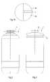
- Figure 1shows a container 1 for a beverage containing a gas, in particular beer, comprises a casing 2 made by stretch blow moulding a polyester preform, in particular PET (polyethylene terephthalate).
- the casing 2comprises a substantially cylindrical middle portion 2A and top and bottom domes 2B, 2C.
- the top dome 2Bhas a central opening 3 formed by the non-deformed part of the preform.
- valve part 4 for dispensing the beverage from the containeris snap-fitted to the opening 3.
- the valve part 4comprises an outer jacket 5, an inner jacket 6 slidably received inside the outer jacket 6, and a closing element 7 which, in turn, is slidably received inside the inner jacket 6.
- the inner jacket and the closing elementcan be made of a polyolefin such as PE or PP.
- the valve partis made of PA or PET, preferably in its entirety.
- International patent application WO 00/07902see especially page 8, line 12 ff. in conjunction with Figures 4A and 4B ).
- a gastight bag 8 for receiving the beverageis connected to the valve part 4 and located inside the casing 2.
- the bag 8comprises two, in this example polygonal, flexible sheets of a gas and liquid tight laminate, preferably a laminate comprising a sealing layer (e.g., PE or PP), a barrier layer (e.g. aluminum) and one or more further layers (e.g. PA and/or PET), sealed together along their edges, e.g. by means of welding.
- the barrier functioncan be shared with or shifted to the casing rendering the casing impermeable to carbon dioxide, oxygen and/or nitrogen.
- the casingmay comprise additives, a coating or a plurality of layers.
- the casing 2is enveloped by a stretch blow moulded polyester shell 9.
- the shellcomprises two parts 9A, 9B, separated along a circumference, i.e. in hoop direction, of the shell 9.
- the casing 2expands and firmly abuts the inner wall of the shell 9.
- the parts 9A, 9Bare both clamp fitted on the casing 2.
- the shellwas blow moulded from a preform similar to that used for the casing but with a different rim. Also, in contrast to the casing, which preferably should have a smooth shape defined by a cylinder and two domes to withstand internal pressure and to avoid damage to the bag containing a beverage, the shell may be provided with one or more features providing additional functionality.
- the shellmay comprise one or more handles defined in, in particular, the top portion.
- handlesinclude a notch 10 spanning the circumference of the shell 9, as shown in Figures 1A , 3 and 4 , or two grips on opposite sides of the shell or a radial flange 11 extending from the upper rim of the shell, as shown in Figure 2 .
- the top part 9A of the shellfurther comprises a collar 12 extending around the valve part and protecting the same.
- the base 9Bcan be provided with features enabling a stable upright position of the container.
- the shellcomprises a petaloid foot 12, similar to those employed in 1,5 liter bottles for soft drink.
- the footprovides a crumble zone protecting the container when it falls.
- top and base of the shellare preferably shaped to render the container stackable, as shown in Figure 4 .
- the basecomprises a recess which is complementary to the collar or the lobs of the petaloid base define a (non-continuous) recess which corresponds to the collar.
- the containerhas an overall length of approximately 57 cm and a width of approximately 24 cm, yielding an L/D of 2,4.
- the cylindrical portionhas a length of approximately 65% of the overall length of the container.
- Puncture resistanceis further improved if the shell is embossed about its circumference so as to increases the actual or at least effective thickness in the radial direction.
- embossingmay comprises a large number of small protrusions on the outer surface of the shell, yielding e.g. a knurled surface, and/or may comprise a plurality of rings about the circumference of the container and/or a plurality of ribs extending in axial direction.
- embossingmay provide other, additional functions.
- the shellcomprises at least two rings extending about the circumference of the shell and spaced apart in axial direction. Such rings facilitate rolling the container e.g. from a truck to storage and reduce the risk of damage to the inner casing inflicted by small sharps on the surface.
- FIGS 5A and 5Bshow a further embodiment of the container according to the present invention.
- the casing 2is again enveloped by a stretch blow moulded polyester shell 9.
- the shellcomprises two parts 9A, 9B, separated along a circumference, i.e. in hoop direction, of the shell 9, relatively close to the bottom of the shell, such that the top part of the shell is longer than the casing.
- the lower rim of the upper part of the shellextends beyond the bottom of the casing and serves as the foot or part of the foot of the container.
- the wallis corrugated to increase its effective thickness and stiffness and/or the wall is actually thicker, preferably at least two times thicker, than the wall of the cylindrical section of the shell.
- the base 9Bcan be discarded or be used to further increase the strength and stability of the foot.
- the base partis provided with creased and radially extending segments to enhance the stiffness of the base, in turn facilitating a stable upright position of the container, and to provide a crumble zone protecting the container when it falls.
- the base partdefines a petaloid foot 12 and is placed, e.g. pressed, inside the bottom end of the top part of the shell.
- the base partcan be clamped, glued, and/or welded into the top part of the shell.
- the base partwas reversed before being inserted in the bottom end of the top part, thus significantly increasing, e.g. doubling, the wall thickness at the lower rim of the shell.
- the center of the baseis shaped complementary to the bottom end of the casing, thus providing support over a relatively large area.
- the cross-section of the upper rim of the base partdiffers from that of the lower rim of the top part of the shell, both in diameter and in shape.
- the shellis preferably formed with a transition between the two parts 9A, 9B and these parts are each separated from the transition, e.g. by two (laser) cuts in the hoop direction of the shell 9.
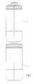
- FIGS 7A to 7Cshow a container according to the present invention which in most respects corresponds to the container shown in Figure 1A and 1B but with a casing 2 and shell 9 having an L/D of approximately 1 and a relatively short cylindrical section.
- the shellis considerably longer than the casing, preferably by a length that corresponds to the length of the cylindrical portion of the casing. In other words, the length of the cylindrical portion of the shell is twice the length of the cylindrical portion of the casing.
- the container shown in Figures 7A to 7Ccomprises an external thread or annular protrusion about the top opening for screwing or snapping e.g. grips onto the container.
- the shellwas blow moulded from a preform similar to that used for the casing but with a different rim.
- the shellmay be provided with one or more features providing additional functionality.
- the stretch blow moulded polyester shellwas found to provide a relatively high retained strength of the container when the shell and casing are punctured, thus avoiding explosive bursting and enabling a more gradual blowing off of the pressurized gas inside the casing.
- the shellis resistant to water and enables a design that is lighter and stronger than containers having a cardboard shell. Due to the increased strength, the container according to the present invention is in principle suitable for beverages containing high concentrations of gas, e.g. 7 gram/liter carbon dioxide, at higher temperatures, e.g. 40°C.
- both the casing and the shellare stretch blow moulded from a preform
- logisticscan be simplified e.g. by supplying just preforms and bags to brewers the containers can be mold blown and assembled on site, avoiding bulky transport.
- the containercan be equipped with a spear extending from the valve part to the bottom of the casing.
Landscapes
- Engineering & Computer Science (AREA)
- Mechanical Engineering (AREA)
- Containers Having Bodies Formed In One Piece (AREA)
- Packages (AREA)
- Containers And Packaging Bodies Having A Special Means To Remove Contents (AREA)
- Details Of Rigid Or Semi-Rigid Containers (AREA)
- Rigid Containers With Two Or More Constituent Elements (AREA)
- Blow-Moulding Or Thermoforming Of Plastics Or The Like (AREA)
- Devices For Use In Laboratory Experiments (AREA)
Description
- The invention relates to a container for liquids, such as beverages, e.g. beer, soft drink and wine, and liquids with a relatively high viscosity, e.g. edible oil, comprising a blow moulded polyester and preferably spherical or spheroid casing, a valve for dispensing the liquid from the container, and an inlet for introducing a propellant, which inlet is typically integrated in the valve.
EP 862 535 EP 1 736 421EP 2 038 187- Many containers for liquids are subjected during use to high internal pressures. E.g., beverages containing a gas should be maintained at an elevated pressure, typically in a range from 1 to 4 bar (overpressure), to prevent the gas from escaping the beverage. Also, liquids having a relatively high viscosity and liquids that are dispensed from a lower level, e.g. from a cellar, require a relatively high pressure in the container to overcome friction and hydrostatic pressure, respectively. High temperatures and non-observance of safety guidelines can also lead to high internal pressures.
- During dispensing, the liquid content of the container is gradually replaced by pressurized gas. Pressurized gas has a high energy content, which means that if the container is cut, punctured or otherwise damaged and fails, it will burst in an explosive manner. Explosive bursting may result in shrapnel and injury, e.g. damaged hearing of people close by.
- In practice, explosive bursting occurs when the container has been installed for dispensing, e.g. through contact with cigarettes, hot air outlets of coolers or sharps behind the bar or stress cracking resulting from exposure to aggressive (caustic) cleaning agents. Explosive bursting also occurs when users want to dispose of an empty container and - disregarding safety guidelines - cut or stab the container with a knife or other implement.
- It is an object of the present invention to provide a container that is relatively lightweight and yet more resistant to explosive bursting.
- To this end, the container according to the invention is characterized in that the casing is enveloped by a stretch blow moulded polyester shell. In an embodiment, the shell supports the casing at least when the latter is pressurized, e.g. the internal pressure urges the casing against the shell.
- The stretch blow moulded polyester shell was found to provide a relatively high retained strength of the container after the shell and casing have been cut, punctured or otherwise damaged, thus raising the threshold pressure at which the container explodes. Below this threshold, the pressurized gas inside the casing will typically blow off rather then causing the container to explode. In addition, the shell enables a design that is lighter than containers having a cardboard or e.g. HDPE shell and/or increases design freedom especially with regard to external features, e.g. a stable base as will be explained in more detail below.
- In an embodiment, the burst strength of the container is at least 20%, preferably at least 30% higher than the burst strength of just the casing. Burst strength is defined as the pressure, in bar, at which the container respectively the casing bursts, when at 20°C and when the pressure is gradually increased with 1 bar per 10 seconds.
- In a further embodiment, the relative expansion of the container, when exposed to 5 bar internal pressure and 40°C during 2 days, is less than 3%, preferably less than 2%, more preferably less than 1,5% higher than the expansion of an identical container exposed to 2 bar internal pressure and 20°C during 2 days. Low expansion is especially relevant for liquids containing a gas with low solubility. Nitrogen (N2), for instance, has a poor solubility in water and thus only a small amount of nitrogen can be added to beer. When the volume of the container increases permanently by only a small percentage, e.g. due to creep at elevated temperatures, a large percentage of the nitrogen will escape from the beer and taste, texture, and dispensing behavior of the beer will deteriorate. This phenomenon can be reduced with the shell according to the present invention.
- In an embodiment, which, incidentally, is also useful in containers comprising casings and shells made of other polymers, the shell comprises two separate parts, e.g. divided along a circumference of the shell, and at least one of the parts, preferably the top part, is clamp fitted on the casing when the latter is pressurized. The shell can be blow moulded from a preform and additional means, such as a lid, necessary for inserting the casing into the shell and subsequently closing the shell may be avoided. In this context, clamp fitted implies that a force of at least 300 N, preferably at least 500 N in axial direction is required to separate the parts of the shell from the casing. I.e., when lifting a container holding twenty liters, or thirty or fifty liters as the case may be, of a beverage by the shell, the casing will not slide with respect to the shell.
- The remaining part of the shell can be secured, e.g. by clamping, glueing and/or welding, in the bottom side of the part clamp fitted on the casing.
- In an embodiment, the two parts overlap, preferably by at least 1 centimeter, more preferably by at least 5 centimeters. This overlap may extend e.g. over the whole cylindrical section of the container resulting in a three layered structure in this part of the container.
- Instead of the remaining part of the shell, a separately formed foot, optionally made of a different material, can be secured in the shell and/or to the casing.
- In a further embodiment, the rim of one part of the shell overlaps the rim of the other part of the shell. In a further embodiment, the parts of the shell are glued or taped to the casing.
- The stretch blow moulded shell suppresses or prevents explosive bursting even in elongate containers, e.g. containers having a relatively high length to width ratio (L/D) and/or a relatively long cylindrical portion. Such shapes facilitate logistics, e.g. more containers can be placed on a pallet, and facilitate cooling, e.g. four containers fit in a standard size refrigerator. In an embodiment, the casing has an internal volume of at least 10, preferably at least 15, more preferably at least 20 liters and the length to width ratio (L/D) of the casing is in excess of 1,5, preferably in excess of 2. In another embodiment, the container comprises a cylindrical portion that extends over at least 25%, preferably at least 40%, more preferably at least 50% of the height of the container.
- In an embodiment, the wall thickness of both the casing and the shell is in a range from 0,1 to 1,0 mm, preferably in a range from 0,3 to 0,6 mm, providing a total wall thickness of up to 2,0 mm, and, e.g. if parts of the shell overlap each other, locally even up to 3,0 mm, which currently cannot be achieved by blowing a single preform.
- Puncture resistance is further improved if the shell is embossed about its circumference so as to increase the actual or at least the effective thickness in the radial direction. Also, embossing reduces the risk of damage to the container when the container is rolled over a rough surface e.g. from a truck to storage.
- In a further embodiment, the container is filled with a pressurized gas and no beverage, i.e. the container is pressurized prior to filling, e.g. with air or carbon dioxide and/or nitrogen at a pressure in excess of 1,5 bar. Thus, the container can be readily filled with a liquid containing a gas, such as beer.
WO 00/78665 US 2010/0077790 relates to a plastic beer keg including an outer container and an inner liner. A removable lid is secured over an opening to the container to enclose the liner. In use, the lid can be removed and ice placed in the container directly on the liner, ice flows into gaps between the liner and the container to provide rapid cooling of the content of the liner. The liner may be PET, the container and lid may be HDPE, polypropylene or another suitable material.EP 389 191 - Within the framework of the present invention "stretch blow moulding" refers to blow moulding and thus stretching a preform, in both the circumferential (hoop) direction and the axial direction.
- The term "spheroid" includes any shape generated by a half-revolution of a circle or a square or rectangle with rounded corners or an ellipse or oval about its major axis or minor axis.
- The invention will now be explained in more detail with reference to the drawings, which show a preferred embodiment of the present invention.
Figures 1A and1B show a cross-section through and a detail of a container according to the present invention.Figures 2 to 4 show a stack and variations of the container inFigures 1A and1B .Figures 5A/5B and 6A/6B show cross-sections and bottom views of containers according to the present invention with a base providing enhanced stability.Figures 7A to 7C show cross-sections of a container according to the present invention comprising a cylindrical portion with increased wall thickness.- The drawings are not necessarily to scale and details, which are not necessary for understanding the present invention, may have been omitted. Further, elements that are at least substantially identical or that perform an at least substantially identical function are denoted by the same numeral.
Figure 1 shows acontainer 1 for a beverage containing a gas, in particular beer, comprises acasing 2 made by stretch blow moulding a polyester preform, in particular PET (polyethylene terephthalate). Thecasing 2 comprises a substantially cylindricalmiddle portion 2A and top andbottom domes top dome 2B has acentral opening 3 formed by the non-deformed part of the preform.- A
valve part 4 for dispensing the beverage from the container is snap-fitted to theopening 3. In this example, thevalve part 4 comprises anouter jacket 5, an inner jacket 6 slidably received inside the outer jacket 6, and a closing element 7 which, in turn, is slidably received inside the inner jacket 6. The inner jacket and the closing element can be made of a polyolefin such as PE or PP. In general, it is preferred that the valve part is made of PA or PET, preferably in its entirety. For more details on this and other suitable valve parts reference is made to International patent applicationWO 00/07902 page 8,line 12 ff. in conjunction withFigures 4A and 4B ). - In this example, a
gastight bag 8 for receiving the beverage is connected to thevalve part 4 and located inside thecasing 2. Thebag 8 comprises two, in this example polygonal, flexible sheets of a gas and liquid tight laminate, preferably a laminate comprising a sealing layer (e.g., PE or PP), a barrier layer (e.g. aluminum) and one or more further layers (e.g. PA and/or PET), sealed together along their edges, e.g. by means of welding. In general, the barrier function can be shared with or shifted to the casing rendering the casing impermeable to carbon dioxide, oxygen and/or nitrogen. To this end, the casing may comprise additives, a coating or a plurality of layers. - In accordance with the invention, the
casing 2 is enveloped by a stretch blow mouldedpolyester shell 9. In the example shown inFigure 1 , the shell comprises twoparts shell 9. When pressurized, thecasing 2 expands and firmly abuts the inner wall of theshell 9. Thus, theparts casing 2. - The shell was blow moulded from a preform similar to that used for the casing but with a different rim. Also, in contrast to the casing, which preferably should have a smooth shape defined by a cylinder and two domes to withstand internal pressure and to avoid damage to the bag containing a beverage, the shell may be provided with one or more features providing additional functionality.
- E.g., the shell may comprise one or more handles defined in, in particular, the top portion. Examples of such handles include a
notch 10 spanning the circumference of theshell 9, as shown inFigures 1A ,3 and4 , or two grips on opposite sides of the shell or aradial flange 11 extending from the upper rim of the shell, as shown inFigure 2 . - In the example shown in
Figures 1A ,3 and4 , thetop part 9A of the shell further comprises acollar 12 extending around the valve part and protecting the same. - The
base 9B can be provided with features enabling a stable upright position of the container. In the example, the shell comprises apetaloid foot 12, similar to those employed in 1,5 liter bottles for soft drink. In addition to providing a stable base, the foot provides a crumble zone protecting the container when it falls. - Further, the top and base of the shell are preferably shaped to render the container stackable, as shown in
Figure 4 . The base comprises a recess which is complementary to the collar or the lobs of the petaloid base define a (non-continuous) recess which corresponds to the collar. - The container has an overall length of approximately 57 cm and a width of approximately 24 cm, yielding an L/D of 2,4. The cylindrical portion has a length of approximately 65% of the overall length of the container.
- Puncture resistance is further improved if the shell is embossed about its circumference so as to increases the actual or at least effective thickness in the radial direction. In general, embossing may comprises a large number of small protrusions on the outer surface of the shell, yielding e.g. a knurled surface, and/or may comprise a plurality of rings about the circumference of the container and/or a plurality of ribs extending in axial direction. Also, embossing may provide other, additional functions. In an embodiment, the shell comprises at least two rings extending about the circumference of the shell and spaced apart in axial direction. Such rings facilitate rolling the container e.g. from a truck to storage and reduce the risk of damage to the inner casing inflicted by small sharps on the surface.
Figures 5A and 5B show a further embodiment of the container according to the present invention. In this embodiment, thecasing 2 is again enveloped by a stretch blow mouldedpolyester shell 9. The shell comprises twoparts shell 9, relatively close to the bottom of the shell, such that the top part of the shell is longer than the casing. As a result, the lower rim of the upper part of the shell extends beyond the bottom of the casing and serves as the foot or part of the foot of the container. To further increase stability, it is preferred that, at the rim, the wall is corrugated to increase its effective thickness and stiffness and/or the wall is actually thicker, preferably at least two times thicker, than the wall of the cylindrical section of the shell.- The
base 9B can be discarded or be used to further increase the strength and stability of the foot. In this example, the base part is provided with creased and radially extending segments to enhance the stiffness of the base, in turn facilitating a stable upright position of the container, and to provide a crumble zone protecting the container when it falls. More specifically, the base part defines apetaloid foot 12 and is placed, e.g. pressed, inside the bottom end of the top part of the shell. The base part can be clamped, glued, and/or welded into the top part of the shell. - In the embodiment shown in
Figures 6A and 6B , the base part was reversed before being inserted in the bottom end of the top part, thus significantly increasing, e.g. doubling, the wall thickness at the lower rim of the shell. The center of the base is shaped complementary to the bottom end of the casing, thus providing support over a relatively large area. - As is apparent from
Figures 5B and 6B , the cross-section of the upper rim of the base part differs from that of the lower rim of the top part of the shell, both in diameter and in shape. Thus, the shell is preferably formed with a transition between the twoparts shell 9. Figures 7A to 7C show a container according to the present invention which in most respects corresponds to the container shown inFigure 1A and1B but with acasing 2 andshell 9 having an L/D of approximately 1 and a relatively short cylindrical section. The shell is considerably longer than the casing, preferably by a length that corresponds to the length of the cylindrical portion of the casing. In other words, the length of the cylindrical portion of the shell is twice the length of the cylindrical portion of the casing. When the shell is separated along a circumference, i.e. in hoop direction and preferably halfway the height of theshell 9, the casing is clamped inside the upper half and the upper half, now containing the casing, is clamped in the lower half, the wall thickness of the shell is doubled at the cylindrical portion.- Further, the container shown in
Figures 7A to 7C comprises an external thread or annular protrusion about the top opening for screwing or snapping e.g. grips onto the container. - In the above examples, the shell was blow moulded from a preform similar to that used for the casing but with a different rim. Also, in contrast to the casing, which preferably should have a smooth shape defined by a cylinder and two domes to withstand internal pressure and to avoid damage to the bag containing a beverage, the shell may be provided with one or more features providing additional functionality.
- The stretch blow moulded polyester shell was found to provide a relatively high retained strength of the container when the shell and casing are punctured, thus avoiding explosive bursting and enabling a more gradual blowing off of the pressurized gas inside the casing. In addition, the shell is resistant to water and enables a design that is lighter and stronger than containers having a cardboard shell. Due to the increased strength, the container according to the present invention is in principle suitable for beverages containing high concentrations of gas, e.g. 7 gram/liter carbon dioxide, at higher temperatures, e.g. 40°C.
- Further, as both the casing and the shell are stretch blow moulded from a preform, logistics can be simplified e.g. by supplying just preforms and bags to brewers the containers can be mold blown and assembled on site, avoiding bulky transport.
- The invention is not restricted to the above-described embodiments which can be varied in a number of ways within the scope of the claims. For instance, instead of a bag for containing the beverage, the container can be equipped with a spear extending from the valve part to the bottom of the casing.
Claims (16)
- Container (1) for liquids, such as beverages and oils, comprising a blow moulded polyester casing (2), a valve (4) for dispensing the liquid from the container, and an inlet for introducing a propellant,characterized in that the casing (2) is enveloped by a stretch blow moulded polyester shell (9).
- Container (1) according to claim 1, wherein the shell (9) supports the casing (2) at least when the latter is pressurized.
- Container (1) according to claim 1 or 2, wherein the shell (9) comprises two separate parts (9A, 9B), e.g. divided along a circumference of the shell, and at least one of the parts (9A) is clamp fitted on the casing (2) when the latter is pressurized.
- Container (1) according to claim 3, wherein the remaining part (9B) is secured in the open end of the part (9A) that is clamp fitted on the casing.
- Container (1) according to claim 3 or 4, wherein the two parts overlap, preferably by at least 1 centimeter.
- Container (1) according to any one of the preceding claims, wherein the burst strength of the container (1) is at least 20%, preferably at least 30% higher than the burst strength of the casing (2).
- Container (1) according to any one of the preceding claims, wherein the relative expansion of the container when exposed to 5 bar internal pressure and 40°C during 2 days is less than 3%, preferably less than 2%, more preferably less than 1,5%.
- Container (1) according to any one of the preceding claims, wherein the casing (2) has an internal volume of at least 10 liters and wherein the length to width ratio (L/D) of the casing (2) is in excess of 1,5, preferably in excess of 2 and/or wherein the container (1) comprises a cylindrical portion (2A) that extends over at least 25%, preferably at least 40%, more preferably at least 50% of the height of the container (1).
- Container (1) according to any one of the preceding claims, wherein the combined wall thickness of the casing (2) and the shell (9) is in excess of 0,8 mm, preferably in excess of 1,0 mm.
- Container (1) according to any one of the preceding claims, wherein the shell (9) is embossed about its circumference, thus increasing the actual or at least the effective thickness in the radial direction.
- Container (1) according to any one of the preceding claims, comprising a liquid-tight inner container (4) of a flexible material located inside the casing for containing the liquid and communicating with the valve (4).
- Container (1) according to claim 11, wherein the casing (2) is impermeable to carbon dioxide, oxygen and/or nitrogen.
- Container (1) according to any one of the preceding claims, wherein the casing (2) is pre-filled with a pressurized gas.
- Container (1) according to any one of the preceding claims, wherein the polyester of the casing (2) and the shell (9) is polyethylene terephthalate (PET), preferably recycled polyethylene terephthalate (PET).
- Container (1) according to any one of the preceding claims, wherein the casing (2) and the shell (9) are transparent.
- Container (1) according to any one of the preceding claims, wherein the shell (9) comprises at least one blow moulded handle (10) and/or a blow moulded foot (12).
Priority Applications (6)
| Application Number | Priority Date | Filing Date | Title |
|---|---|---|---|
| RS20170028ARS55587B1 (en) | 2010-04-27 | 2011-04-26 | Container for liquids |
| EP11717245.2AEP2566777B1 (en) | 2010-04-27 | 2011-04-26 | Container for liquids |
| DE602011031883.7ADE602011031883C5 (en) | 2010-04-27 | 2011-04-26 | CONTAINERS FOR LIQUIDS |
| HRP20170035TTHRP20170035T1 (en) | 2010-04-27 | 2011-04-26 | LIQUID TANK |
| PL11717245TPL2566777T3 (en) | 2010-04-27 | 2011-04-26 | Container for liquids |
| CY20171100015TCY1118418T1 (en) | 2010-04-27 | 2017-01-05 | LIQUID CONTAINER |
Applications Claiming Priority (4)
| Application Number | Priority Date | Filing Date | Title |
|---|---|---|---|
| EP10161157 | 2010-04-27 | ||
| EP10190570 | 2010-11-09 | ||
| EP11717245.2AEP2566777B1 (en) | 2010-04-27 | 2011-04-26 | Container for liquids |
| PCT/EP2011/056553WO2011134949A1 (en) | 2010-04-27 | 2011-04-26 | Container for liquids |
Publications (2)
| Publication Number | Publication Date |
|---|---|
| EP2566777A1 EP2566777A1 (en) | 2013-03-13 |
| EP2566777B1true EP2566777B1 (en) | 2016-11-02 |
Family
ID=44211768
Family Applications (1)
| Application Number | Title | Priority Date | Filing Date |
|---|---|---|---|
| EP11717245.2AActiveEP2566777B1 (en) | 2010-04-27 | 2011-04-26 | Container for liquids |
Country Status (38)
| Country | Link |
|---|---|
| US (2) | US10815033B2 (en) |
| EP (1) | EP2566777B1 (en) |
| JP (1) | JP6088423B2 (en) |
| KR (1) | KR101797790B1 (en) |
| CN (2) | CN107235235A (en) |
| AP (1) | AP2012006565A0 (en) |
| AR (1) | AR081898A1 (en) |
| AU (1) | AU2011246532B2 (en) |
| BR (1) | BR112012027428B1 (en) |
| CA (1) | CA2797256C (en) |
| CL (1) | CL2012002987A1 (en) |
| CO (1) | CO6640252A2 (en) |
| CU (1) | CU24470B1 (en) |
| CY (1) | CY1118418T1 (en) |
| DE (1) | DE602011031883C5 (en) |
| DK (1) | DK2566777T3 (en) |
| DO (1) | DOP2012000276A (en) |
| EA (1) | EA028713B1 (en) |
| EC (1) | ECSP12012275A (en) |
| ES (1) | ES2611599T3 (en) |
| GT (1) | GT201200288A (en) |
| HR (1) | HRP20170035T1 (en) |
| HU (1) | HUE031296T2 (en) |
| IL (1) | IL222499B (en) |
| LT (1) | LT2566777T (en) |
| MA (1) | MA34233B1 (en) |
| MX (1) | MX340690B (en) |
| MY (1) | MY167022A (en) |
| NZ (1) | NZ603067A (en) |
| PE (1) | PE20130921A1 (en) |
| PH (1) | PH12012502114A1 (en) |
| PL (1) | PL2566777T3 (en) |
| PT (1) | PT2566777T (en) |
| RS (1) | RS55587B1 (en) |
| SG (2) | SG184900A1 (en) |
| TN (1) | TN2012000504A1 (en) |
| WO (1) | WO2011134949A1 (en) |
| ZA (1) | ZA201208890B (en) |
Cited By (2)
| Publication number | Priority date | Publication date | Assignee | Title |
|---|---|---|---|---|
| WO2020146786A1 (en) | 2019-01-10 | 2020-07-16 | Sandymount Technologies Corporation | Unit for dispensing ultra-high gravity beers on draft |
| WO2021158975A1 (en) | 2020-02-07 | 2021-08-12 | Alfa Laval Sandymount Technologies Corporation | Unit for dispensing ultra-high gravity fermented beverages on draft |
Families Citing this family (16)
| Publication number | Priority date | Publication date | Assignee | Title |
|---|---|---|---|---|
| EP2566777B1 (en)* | 2010-04-27 | 2016-11-02 | Eurokeg B.V. | Container for liquids |
| GB201205243D0 (en) | 2012-03-26 | 2012-05-09 | Kraft Foods R & D Inc | Packaging and method of opening |
| EP2690028A1 (en)* | 2012-07-27 | 2014-01-29 | Eurokeg B.V. | Container for liquids |
| GB2511560B (en) | 2013-03-07 | 2018-11-14 | Mondelez Uk R&D Ltd | Improved Packaging and Method of Forming Packaging |
| GB2511559B (en) | 2013-03-07 | 2018-11-14 | Mondelez Uk R&D Ltd | Improved Packaging and Method of Forming Packaging |
| EP2842880A1 (en)* | 2013-08-28 | 2015-03-04 | Eurokeg B.V. | Container for liquids |
| EP2881147A1 (en)* | 2013-12-06 | 2015-06-10 | J.A.S. Koekkoek Holding B.V. | A system suitable for proportioning foam and methods of use of the system |
| KR101654685B1 (en) | 2015-10-15 | 2016-09-22 | 신한산업 (주) | Inspect equipment keg filler strain |
| WO2018156308A1 (en) | 2017-02-21 | 2018-08-30 | The Procter & Gamble Company | Methods of making vented flexible containers |
| WO2018156309A1 (en) | 2017-02-22 | 2018-08-30 | The Procter & Gamble Company | Methods of making flexible containers with structural support frames |
| US11338975B2 (en) | 2018-05-16 | 2022-05-24 | The Procter & Gamble Company | Container blanks for flexible packages and methods of making flexible packages |
| CN108946640A (en) | 2018-06-08 | 2018-12-07 | 邱长富 | A kind of Double wine cask |
| EP3629255A1 (en) | 2018-09-27 | 2020-04-01 | Eurokeg B.V. | Method and computer for providing a raw material input |
| CN110171794B (en)* | 2019-05-10 | 2021-04-27 | 塔罗斯科技股份有限公司 | Liquid container |
| DE102019129504B4 (en) | 2019-10-31 | 2021-09-23 | Protechna S.A. | Plastic containers for liquids and methods of manufacturing a plastic container |
| RU2762450C1 (en)* | 2021-09-16 | 2021-12-21 | Михаил Николаевич Мирошниченко | Stackable reusable keg device |
Family Cites Families (65)
| Publication number | Priority date | Publication date | Assignee | Title |
|---|---|---|---|---|
| FR1412075A (en)* | 1964-10-09 | 1965-09-24 | Pressure vessel or keg, more particularly beer barrel | |
| US4242884A (en)* | 1979-05-07 | 1981-01-06 | Kotschwar Rex R | Beverage cooler |
| US4387833A (en)* | 1980-12-16 | 1983-06-14 | Container Industries, Inc. | Apparatus for containing and dispensing fluids under pressure and method of producing same |
| US4378069A (en)* | 1981-04-21 | 1983-03-29 | Magna Technologies, Inc. | Pouch with pour spout |
| US4458830A (en)* | 1981-05-18 | 1984-07-10 | Werding Winfried J | Appliance for discharging a non-compressible liquid, creamy or pasty product under pressure |
| US4491247A (en)* | 1981-07-21 | 1985-01-01 | Nitchman Harold L | System, apparatus, and method of dispensing a liquid from a semi-bulk disposable container |
| US4678101A (en)* | 1981-07-21 | 1987-07-07 | Nitchman Harold L | Dispensing container closure |
| US4531656A (en)* | 1981-07-21 | 1985-07-30 | Nitchman Harold L | System, apparatus and method of dispensing a liquid from disposable container and a container therefor |
| GB2171382A (en)* | 1985-02-21 | 1986-08-28 | Bxl Plastics Ltd | Container with inner flexible bag |
| US4867348A (en)* | 1985-05-17 | 1989-09-19 | Adolph Coors Company | Disposable package for use in marketing fluids |
| DE3886184D1 (en)* | 1987-06-26 | 1994-01-20 | Werding Winfried J | DEVICE FOR STORING AND CONTROLLED DELIVERY OF PRODUCTS UNDER PRESSURE AND METHOD FOR THE PRODUCTION THEREOF. |
| JPH0718585B2 (en) | 1987-11-19 | 1995-03-06 | 松下電器産業株式会社 | Remote control device for air conditioner |
| GB8906409D0 (en) | 1989-03-21 | 1989-05-04 | Lambrechts Nv | Container for liquids |
| US5301838A (en)* | 1991-01-23 | 1994-04-12 | Continental Pet Technologies, Inc. | Multilayer bottle with separable inner layer and method for forming same |
| US5238150A (en)* | 1991-02-01 | 1993-08-24 | William Dispenser Corporation | Dispenser with compressible piston assembly for expelling product from a collapsible reservoir |
| US5090095A (en)* | 1991-02-08 | 1992-02-25 | Display Products, Inc. | Drapery clip |
| US5129534A (en)* | 1991-07-29 | 1992-07-14 | Sonoco Products Company | Composite keg |
| US5368195A (en)* | 1993-05-13 | 1994-11-29 | Pleet; Lawrence | Pressurized bag-in-bottle liquid dispensing system |
| AUPO868497A0 (en)* | 1997-08-21 | 1997-09-11 | Commonwealth Scientific And Industrial Research Organisation | New uses for oxygen scavenging compositions |
| EP0687640B1 (en)* | 1994-06-15 | 2001-09-05 | Präzisions-Werkzeuge AG | Perforated dip tube for double walled pressurized containers |
| NL9500149A (en) | 1995-01-27 | 1996-09-02 | Euro Maintenance Lease Prod Bv | Collapsible holder. |
| US5613622A (en)* | 1995-06-13 | 1997-03-25 | Isk Biosciences Corporation | Tank having an inner bladder |
| US5927551A (en)* | 1996-11-01 | 1999-07-27 | Exxel Container, Inc. | Power assembly apparatus |
| JPH1134152A (en)* | 1997-07-22 | 1999-02-09 | Nissei Asb Mach Co Ltd | Large-sized container and its molding method |
| WO1999011563A1 (en)* | 1997-09-04 | 1999-03-11 | Heineken Technical Services B.V. | Assembly for storing and dispensing beer and other carbonated beverages |
| NL1009812C2 (en) | 1998-08-05 | 2000-02-08 | Euro Maintenance Lease Prod Bv | Shut-off valve for a container. |
| US6270868B1 (en)* | 1998-11-17 | 2001-08-07 | Inoac Packaging Group Inc. | Composite container with stabilized base |
| JP2000232297A (en) | 1999-02-12 | 2000-08-22 | Hitachi Metals Ltd | Electromagnetic wave absorber |
| AUPQ105099A0 (en) | 1999-06-18 | 1999-07-08 | Carlton And United Breweries Limited | Beer container |
| US6887553B1 (en) | 1999-06-23 | 2005-05-03 | 3M Innovative Properties Company | Roll of longitudinally folded masking material |
| US6536617B2 (en)* | 2001-02-15 | 2003-03-25 | Colgate-Palmolive Company | Bottle with closure holding structure |
| US6974447B2 (en) | 2001-04-17 | 2005-12-13 | Baxter International Inc. | High gas barrier receptacle and closure assembly |
| ATE490932T1 (en)* | 2002-06-26 | 2010-12-15 | Daizo Co Ltd | PACKAGING CONTAINER FOR DISCHARGING MULTIPLE CONTENTS, PACKAGING PRODUCT WITH THE PACKAGING CONTAINER AND METHOD FOR PRODUCING THE PACKAGING PRODUCT |
| DE20212802U1 (en)* | 2002-08-15 | 2002-11-07 | Kersten, Olaf, Dr.-Ing., 47802 Krefeld | Dispensing valve with bag |
| US7597124B2 (en)* | 2004-06-07 | 2009-10-06 | Claude Litto | Preservation and dispensation by volumetric displacement utilizing potential energy conversion |
| DE602006001851D1 (en)* | 2005-02-15 | 2008-08-28 | Goemar Lab Sa | DEVICE FOR DISPENSING FLUIDS, PARTICULARLY MEDICINAL PRODUCTS UNDER PRESSURE |
| US7820257B2 (en)* | 2005-05-11 | 2010-10-26 | The Coca-Cola Company | Preforms for preparing lightweight stretch blow molded PET copolymer containers and methods for making and using same |
| ES2325167T3 (en)* | 2005-06-24 | 2009-08-27 | Eurokeg B.V. | CONTAINER FOR FLUIDS, IN PARTICULAR LIQUIDS. |
| US20070241132A1 (en)* | 2006-04-17 | 2007-10-18 | The Procter & Gamble Company | Pressurized package |
| US20080247684A1 (en)* | 2006-05-25 | 2008-10-09 | Binks Craig C | Flexible beverage container |
| PT2038187E (en) | 2006-06-28 | 2010-12-24 | Eurokeg Bv | Container for fluids, insert and method of filling a container. |
| JP4926563B2 (en)* | 2006-06-28 | 2012-05-09 | 東京応化工業株式会社 | Container for fluid and container containing fluid using the same |
| EP1880824A1 (en) | 2006-07-20 | 2008-01-23 | Aisapack Holding SA | Preform for manufacturing a packaging by blow moulding, method for blow moulding a preform and manufactured packaging |
| US20080110928A1 (en)* | 2006-11-13 | 2008-05-15 | Eurokeg B.V. | Container for fluids, in particular liquids, and a method of making a container |
| US9944453B2 (en)* | 2007-04-19 | 2018-04-17 | Anheuser-Busch Inbev S.A. | Integrally blow-moulded bag-in-container having an inner layer and the outer layer made of the same material and preform for making it |
| US20080257846A1 (en) | 2007-04-19 | 2008-10-23 | Inbev S.A. | Integrally blow-moulded bag-in-container having interface vents opening to the atmosphere at location adjacent to bag's mouth; preform for making it; and processes for producing the preform and bag-in-container |
| US20090045222A1 (en)* | 2007-08-14 | 2009-02-19 | Power Container Corp. | Bag of variable volume, device suitable for dispensing fluids comprising said bag, and process for filling said device |
| FR2921642B1 (en)* | 2007-09-28 | 2011-07-15 | Power Container Corp | DEVICE FOR DISPENSING FLUID PRODUCT, METHOD OF MAKING SUCH DEVICE AND APPARATUS FOR IMPLEMENTING SUCH A METHOD |
| ATE528233T1 (en)* | 2007-08-28 | 2011-10-15 | Entegris Inc | METHOD AND DEVICE FOR DISPENSING FLUID |
| MX2010003162A (en)* | 2007-09-22 | 2010-04-09 | Dispensing Technologies Bv | Container with deformable inner container and method for manufacture thereof. |
| US8360278B2 (en)* | 2007-12-05 | 2013-01-29 | Freeze King | Pressure vessel, system and/or method for dispensing a comestible mixture |
| US9475607B2 (en)* | 2008-10-01 | 2016-10-25 | Rehrig Pacific Company | Plastic beer keg |
| JP5260749B2 (en)* | 2008-10-23 | 2013-08-14 | ザ プロクター アンド ギャンブル カンパニー | Material distribution system and manufacturing method thereof |
| AU2010239438B2 (en)* | 2009-04-20 | 2016-08-11 | Rehrig Pacific Company | Plastic beer keg |
| NL2003131C2 (en)* | 2009-07-03 | 2011-01-04 | Heineken Supply Chain Bv | Preform and method for forming a container. |
| KR20130004500A (en)* | 2010-03-10 | 2013-01-10 | 에코 로직 브랜드 인크 | Containers for holding materials |
| EP2566777B1 (en) | 2010-04-27 | 2016-11-02 | Eurokeg B.V. | Container for liquids |
| BE1019342A5 (en)* | 2010-05-20 | 2012-06-05 | Dispack Projects Nv | BARREL FROM PLASTIC, METHOD FOR MANUFACTURING THEM, AND RING FOR A BARREL. |
| US8939215B2 (en)* | 2010-05-28 | 2015-01-27 | The Subsea Company | Gasless pilot accumulator |
| ES2451394T3 (en)* | 2010-11-09 | 2014-03-26 | Rehrig Pacific Company | Plastic beer barrel |
| ES2704670T3 (en)* | 2010-12-17 | 2019-03-19 | Dispensing Tech Bv | Preform for liquid pushing applications |
| US9211993B2 (en)* | 2011-03-01 | 2015-12-15 | Advanced Technology Materials, Inc. | Nested blow molded liner and overpack and methods of making same |
| EP2766281A4 (en)* | 2011-10-13 | 2015-05-27 | Advanced Tech Materials | Liner-based shipping and dispensing containers for the substantially sterile storage, shipment, and dispense of materials |
| EP2842880A1 (en)* | 2013-08-28 | 2015-03-04 | Eurokeg B.V. | Container for liquids |
| GB2532223B (en)* | 2014-11-11 | 2017-11-15 | Petainer Large Container Ip Ltd | Keg protection assembly |
- 2011
- 2011-04-26EPEP11717245.2Apatent/EP2566777B1/enactiveActive
- 2011-04-26JPJP2013506627Apatent/JP6088423B2/enactiveActive
- 2011-04-26PLPL11717245Tpatent/PL2566777T3/enunknown
- 2011-04-26PHPH1/2012/502114Apatent/PH12012502114A1/enunknown
- 2011-04-26HUHUE11717245Apatent/HUE031296T2/enunknown
- 2011-04-26PEPE2012002085Apatent/PE20130921A1/enactiveIP Right Grant
- 2011-04-26ESES11717245.2Tpatent/ES2611599T3/enactiveActive
- 2011-04-26NZNZ603067Apatent/NZ603067A/enunknown
- 2011-04-26PTPT117172452Tpatent/PT2566777T/enunknown
- 2011-04-26SGSG2012076980Apatent/SG184900A1/enunknown
- 2011-04-26WOPCT/EP2011/056553patent/WO2011134949A1/enactiveApplication Filing
- 2011-04-26CNCN201710417265.5Apatent/CN107235235A/enactivePending
- 2011-04-26DKDK11717245.2Tpatent/DK2566777T3/enactive
- 2011-04-26DEDE602011031883.7Apatent/DE602011031883C5/enactiveActive
- 2011-04-26MAMA35371Apatent/MA34233B1/enunknown
- 2011-04-26MYMYPI2012004634Apatent/MY167022A/enunknown
- 2011-04-26KRKR1020127030414Apatent/KR101797790B1/enactiveActive
- 2011-04-26MXMX2012012478Apatent/MX340690B/enactiveIP Right Grant
- 2011-04-26LTLTEP11717245.2Tpatent/LT2566777T/enunknown
- 2011-04-26BRBR112012027428-7Apatent/BR112012027428B1/enactiveIP Right Grant
- 2011-04-26EAEA201291021Apatent/EA028713B1/ennot_activeIP Right Cessation
- 2011-04-26AUAU2011246532Apatent/AU2011246532B2/enactiveActive
- 2011-04-26APAP2012006565Apatent/AP2012006565A0/enunknown
- 2011-04-26SGSG10201503278SApatent/SG10201503278SA/enunknown
- 2011-04-26CACA2797256Apatent/CA2797256C/enactiveActive
- 2011-04-26ARARP110101427Apatent/AR081898A1/enactiveIP Right Grant
- 2011-04-26CUCU2012000151Apatent/CU24470B1/enunknown
- 2011-04-26USUS13/643,610patent/US10815033B2/enactiveActive
- 2011-04-26RSRS20170028Apatent/RS55587B1/enunknown
- 2011-04-26CNCN2011800290899Apatent/CN102939250A/enactivePending
- 2011-04-26HRHRP20170035TTpatent/HRP20170035T1/enunknown
- 2012
- 2012-10-17ILIL222499Apatent/IL222499B/enactiveIP Right Grant
- 2012-10-19ECECSP12012275patent/ECSP12012275A/enunknown
- 2012-10-22TNTNP2012000504Apatent/TN2012000504A1/enunknown
- 2012-10-23DODO2012000276Apatent/DOP2012000276A/enunknown
- 2012-10-24GTGT201200288Apatent/GT201200288A/enunknown
- 2012-10-25CLCL2012002987Apatent/CL2012002987A1/enunknown
- 2012-11-26ZAZA2012/08890Apatent/ZA201208890B/enunknown
- 2012-11-26COCO12213954Apatent/CO6640252A2/enunknown
- 2017
- 2017-01-05CYCY20171100015Tpatent/CY1118418T1/enunknown
- 2020
- 2020-10-24USUS17/079,441patent/US20210039835A1/ennot_activeAbandoned
Non-Patent Citations (1)
| Title |
|---|
| None* |
Cited By (3)
| Publication number | Priority date | Publication date | Assignee | Title |
|---|---|---|---|---|
| WO2020146786A1 (en) | 2019-01-10 | 2020-07-16 | Sandymount Technologies Corporation | Unit for dispensing ultra-high gravity beers on draft |
| WO2021158975A1 (en) | 2020-02-07 | 2021-08-12 | Alfa Laval Sandymount Technologies Corporation | Unit for dispensing ultra-high gravity fermented beverages on draft |
| US11975959B2 (en) | 2020-02-07 | 2024-05-07 | Alfa Laval Copenhagen A/S | Unit for dispensing ultra-high gravity fermented beverages on draft |
Also Published As
Similar Documents
| Publication | Publication Date | Title |
|---|---|---|
| US20210039835A1 (en) | Container for liquids | |
| EP2038187B1 (en) | Container for fluids, insert and method of filling a container. | |
| AU2006321010B2 (en) | System and method for distribution and dispensing of beverages | |
| CA2920704C (en) | Container for liquids | |
| HK1241331A1 (en) | Container for liquids | |
| HK1179588A (en) | Container for liquids | |
| OA17737A (en) | Container for liquids. |
Legal Events
| Date | Code | Title | Description |
|---|---|---|---|
| PUAI | Public reference made under article 153(3) epc to a published international application that has entered the european phase | Free format text:ORIGINAL CODE: 0009012 | |
| 17P | Request for examination filed | Effective date:20121127 | |
| AK | Designated contracting states | Kind code of ref document:A1 Designated state(s):AL AT BE BG CH CY CZ DE DK EE ES FI FR GB GR HR HU IE IS IT LI LT LU LV MC MK MT NL NO PL PT RO RS SE SI SK SM TR | |
| AX | Request for extension of the european patent | Extension state:BA ME | |
| RIN1 | Information on inventor provided before grant (corrected) | Inventor name:HANSSEN, HUBERT JOSEPH FRANS Inventor name:VEENENDAAL, JAN, DIRK Inventor name:VEENENDAAL, JAN | |
| RAP1 | Party data changed (applicant data changed or rights of an application transferred) | Owner name:EUROKEG B.V. | |
| 17Q | First examination report despatched | Effective date:20160108 | |
| GRAP | Despatch of communication of intention to grant a patent | Free format text:ORIGINAL CODE: EPIDOSNIGR1 | |
| INTG | Intention to grant announced | Effective date:20160810 | |
| GRAS | Grant fee paid | Free format text:ORIGINAL CODE: EPIDOSNIGR3 | |
| GRAA | (expected) grant | Free format text:ORIGINAL CODE: 0009210 | |
| AK | Designated contracting states | Kind code of ref document:B1 Designated state(s):AL AT BE BG CH CY CZ DE DK EE ES FI FR GB GR HR HU IE IS IT LI LT LU LV MC MK MT NL NO PL PT RO RS SE SI SK SM TR | |
| AX | Request for extension of the european patent | Extension state:BA ME | |
| REG | Reference to a national code | Ref country code:GB Ref legal event code:FG4D | |
| REG | Reference to a national code | Ref country code:AT Ref legal event code:REF Ref document number:841590 Country of ref document:AT Kind code of ref document:T Effective date:20161115 Ref country code:CH Ref legal event code:EP | |
| REG | Reference to a national code | Ref country code:IE Ref legal event code:FG4D | |
| REG | Reference to a national code | Ref country code:DE Ref legal event code:R096 Ref document number:602011031883 Country of ref document:DE | |
| REG | Reference to a national code | Ref country code:HR Ref legal event code:TUEP Ref document number:P20170035 Country of ref document:HR | |
| REG | Reference to a national code | Ref country code:RO Ref legal event code:EPE | |
| REG | Reference to a national code | Ref country code:NL Ref legal event code:FP | |
| REG | Reference to a national code | Ref country code:PT Ref legal event code:SC4A Ref document number:2566777 Country of ref document:PT Date of ref document:20170127 Kind code of ref document:T Free format text:AVAILABILITY OF NATIONAL TRANSLATION Effective date:20170117 | |
| REG | Reference to a national code | Ref country code:DK Ref legal event code:T3 Effective date:20170130 | |
| REG | Reference to a national code | Ref country code:SE Ref legal event code:TRGR | |
| REG | Reference to a national code | Ref country code:NO Ref legal event code:T2 Effective date:20161102 | |
| REG | Reference to a national code | Ref country code:HR Ref legal event code:T1PR Ref document number:P20170035 Country of ref document:HR | |
| REG | Reference to a national code | Ref country code:EE Ref legal event code:FG4A Ref document number:E013169 Country of ref document:EE Effective date:20170117 | |
| REG | Reference to a national code | Ref country code:FR Ref legal event code:PLFP Year of fee payment:7 | |
| REG | Reference to a national code | Ref country code:ES Ref legal event code:FG2A Ref document number:2611599 Country of ref document:ES Kind code of ref document:T3 Effective date:20170509 | |
| REG | Reference to a national code | Ref country code:HU Ref legal event code:AG4A Ref document number:E031296 Country of ref document:HU | |
| REG | Reference to a national code | Ref country code:DE Ref legal event code:R097 Ref document number:602011031883 Country of ref document:DE | |
| PG25 | Lapsed in a contracting state [announced via postgrant information from national office to epo] | Ref country code:SM Free format text:LAPSE BECAUSE OF FAILURE TO SUBMIT A TRANSLATION OF THE DESCRIPTION OR TO PAY THE FEE WITHIN THE PRESCRIBED TIME-LIMIT Effective date:20161102 | |
| PLBE | No opposition filed within time limit | Free format text:ORIGINAL CODE: 0009261 | |
| STAA | Information on the status of an ep patent application or granted ep patent | Free format text:STATUS: NO OPPOSITION FILED WITHIN TIME LIMIT | |
| 26N | No opposition filed | Effective date:20170803 | |
| PG25 | Lapsed in a contracting state [announced via postgrant information from national office to epo] | Ref country code:SI Free format text:LAPSE BECAUSE OF FAILURE TO SUBMIT A TRANSLATION OF THE DESCRIPTION OR TO PAY THE FEE WITHIN THE PRESCRIBED TIME-LIMIT Effective date:20161102 | |
| REG | Reference to a national code | Ref country code:DE Ref legal event code:R039 Ref document number:602011031883 Country of ref document:DE Ref country code:DE Ref legal event code:R008 Ref document number:602011031883 Country of ref document:DE | |
| PG25 | Lapsed in a contracting state [announced via postgrant information from national office to epo] | Ref country code:MC Free format text:LAPSE BECAUSE OF FAILURE TO SUBMIT A TRANSLATION OF THE DESCRIPTION OR TO PAY THE FEE WITHIN THE PRESCRIBED TIME-LIMIT Effective date:20161102 | |
| REG | Reference to a national code | Ref country code:FR Ref legal event code:PLFP Year of fee payment:8 | |
| PG25 | Lapsed in a contracting state [announced via postgrant information from national office to epo] | Ref country code:MT Free format text:LAPSE BECAUSE OF NON-PAYMENT OF DUE FEES Effective date:20170426 | |
| REG | Reference to a national code | Ref country code:HR Ref legal event code:ODRP Ref document number:P20170035 Country of ref document:HR Payment date:20190405 Year of fee payment:9 | |
| REG | Reference to a national code | Ref country code:HR Ref legal event code:ODRP Ref document number:P20170035 Country of ref document:HR Payment date:20200407 Year of fee payment:10 | |
| REG | Reference to a national code | Ref country code:DE Ref legal event code:R043 Ref document number:602011031883 Country of ref document:DE | |
| REG | Reference to a national code | Ref country code:HR Ref legal event code:ODRP Ref document number:P20170035 Country of ref document:HR Payment date:20210402 Year of fee payment:11 | |
| REG | Reference to a national code | Ref country code:DE Ref legal event code:R206 Ref document number:602011031883 Country of ref document:DE | |
| REG | Reference to a national code | Ref country code:HR Ref legal event code:ODRP Ref document number:P20170035 Country of ref document:HR Payment date:20220406 Year of fee payment:12 | |
| REG | Reference to a national code | Ref country code:HR Ref legal event code:ODRP Ref document number:P20170035 Country of ref document:HR Payment date:20230404 Year of fee payment:13 | |
| PGFP | Annual fee paid to national office [announced via postgrant information from national office to epo] | Ref country code:MK Payment date:20230403 Year of fee payment:13 | |
| REG | Reference to a national code | Ref country code:HR Ref legal event code:ODRP Ref document number:P20170035 Country of ref document:HR Payment date:20240405 Year of fee payment:14 | |
| PGFP | Annual fee paid to national office [announced via postgrant information from national office to epo] | Ref country code:CY Payment date:20240404 Year of fee payment:14 | |
| PGFP | Annual fee paid to national office [announced via postgrant information from national office to epo] | Ref country code:NL Payment date:20250427 Year of fee payment:15 | |
| PGFP | Annual fee paid to national office [announced via postgrant information from national office to epo] | Ref country code:LU Payment date:20250428 Year of fee payment:15 | |
| REG | Reference to a national code | Ref country code:HR Ref legal event code:ODRP Ref document number:P20170035 Country of ref document:HR Payment date:20250414 Year of fee payment:15 | |
| PGFP | Annual fee paid to national office [announced via postgrant information from national office to epo] | Ref country code:FI Payment date:20250425 Year of fee payment:15 | |
| PGFP | Annual fee paid to national office [announced via postgrant information from national office to epo] | Ref country code:PL Payment date:20250403 Year of fee payment:15 Ref country code:DE Payment date:20250429 Year of fee payment:15 | |
| PGFP | Annual fee paid to national office [announced via postgrant information from national office to epo] | Ref country code:GB Payment date:20250428 Year of fee payment:15 Ref country code:ES Payment date:20250505 Year of fee payment:15 Ref country code:DK Payment date:20250425 Year of fee payment:15 | |
| PGFP | Annual fee paid to national office [announced via postgrant information from national office to epo] | Ref country code:LT Payment date:20250401 Year of fee payment:15 | |
| PGFP | Annual fee paid to national office [announced via postgrant information from national office to epo] | Ref country code:IS Payment date:20250416 Year of fee payment:15 Ref country code:HU Payment date:20250422 Year of fee payment:15 Ref country code:RS Payment date:20250402 Year of fee payment:15 Ref country code:NO Payment date:20250429 Year of fee payment:15 | |
| PGFP | Annual fee paid to national office [announced via postgrant information from national office to epo] | Ref country code:AL Payment date:20250419 Year of fee payment:15 Ref country code:BE Payment date:20250428 Year of fee payment:15 Ref country code:IT Payment date:20250422 Year of fee payment:15 | |
| PGFP | Annual fee paid to national office [announced via postgrant information from national office to epo] | Ref country code:HR Payment date:20250414 Year of fee payment:15 | |
| PGFP | Annual fee paid to national office [announced via postgrant information from national office to epo] | Ref country code:PT Payment date:20250407 Year of fee payment:15 Ref country code:LV Payment date:20250401 Year of fee payment:15 | |
| PGFP | Annual fee paid to national office [announced via postgrant information from national office to epo] | Ref country code:EE Payment date:20250407 Year of fee payment:15 Ref country code:FR Payment date:20250425 Year of fee payment:15 | |
| PGFP | Annual fee paid to national office [announced via postgrant information from national office to epo] | Ref country code:BG Payment date:20250417 Year of fee payment:15 Ref country code:GR Payment date:20250430 Year of fee payment:15 | |
| PGFP | Annual fee paid to national office [announced via postgrant information from national office to epo] | Ref country code:CH Payment date:20250501 Year of fee payment:15 | |
| PGFP | Annual fee paid to national office [announced via postgrant information from national office to epo] | Ref country code:RO Payment date:20250407 Year of fee payment:15 Ref country code:AT Payment date:20250402 Year of fee payment:15 | |
| PGFP | Annual fee paid to national office [announced via postgrant information from national office to epo] | Ref country code:TR Payment date:20250418 Year of fee payment:15 Ref country code:SK Payment date:20250401 Year of fee payment:15 | |
| PGFP | Annual fee paid to national office [announced via postgrant information from national office to epo] | Ref country code:CZ Payment date:20250408 Year of fee payment:15 | |
| PGFP | Annual fee paid to national office [announced via postgrant information from national office to epo] | Ref country code:IE Payment date:20250428 Year of fee payment:15 | |
| PGFP | Annual fee paid to national office [announced via postgrant information from national office to epo] | Ref country code:SE Payment date:20250430 Year of fee payment:15 |