EP2566694B1 - Printing machine - Google Patents
Printing machineDownload PDFInfo
- Publication number
- EP2566694B1 EP2566694B1EP11719222.9AEP11719222AEP2566694B1EP 2566694 B1EP2566694 B1EP 2566694B1EP 11719222 AEP11719222 AEP 11719222AEP 2566694 B1EP2566694 B1EP 2566694B1
- Authority
- EP
- European Patent Office
- Prior art keywords
- printed material
- printing press
- gas jet
- printing
- drying
- Prior art date
- Legal status (The legal status is an assumption and is not a legal conclusion. Google has not performed a legal analysis and makes no representation as to the accuracy of the status listed.)
- Not-in-force
Links
Images


Classifications
- B—PERFORMING OPERATIONS; TRANSPORTING
- B41—PRINTING; LINING MACHINES; TYPEWRITERS; STAMPS
- B41F—PRINTING MACHINES OR PRESSES
- B41F23/00—Devices for treating the surfaces of sheets, webs, or other articles in connection with printing
- B41F23/04—Devices for treating the surfaces of sheets, webs, or other articles in connection with printing by heat drying, by cooling, by applying powders
- B41F23/0403—Drying webs
- B41F23/0423—Drying webs by convection
- B41F23/0426—Drying webs by convection using heated air
Definitions
- the inventionrelates to a printing machine according to claim 1.
- DE 687 293describes a printing machine according to the preamble of claim 1.
- drying deviceswhich generally include a fan, with which the printed material can be acted upon by a gas jet.
- the gasis usually air. However, other gases may be used. Often, the gas has been heated in the drying device by means of a tempering device in order to facilitate the mass transfer of the solvent molecules into the gas stream.
- a problem with the drying of printed materialis that when it is transported on the material, air molecules remain adherent and thus form laminar boundary layers, which make the detachment of solvents more difficult.
- the object of the present inventionis therefore to propose an improved printing machine, in which the drying or the evaporation of solvents is facilitated in the drying of the printed material.
- a deviceis provided with which the basic blowing speed can be modulated.
- the basic blowing speed with this devicecan be varied between a maximum speed and a minimum speed.
- the gas jetcan be acted upon by a vibration with the device mentioned, with the result that the speed of the gas jet varies periodically between the maximum and the minimum speed. Due to the ever-changing air pressures, it is possible, at least in part, to set the laminar boundary layers adhering to the printed and transported material in the printing machine in turbulent motion and to reduce or even completely dissolve these laminar boundary layers.
- the means by which the basic blowing speed is modulatedis an ultrasonic generating device.
- Ultrasoundis particularly good at causing the air to vibrate, causing the laminar boundary layers to detach.
- Ultrasoundcan be generated in comparatively simple ways. At frequencies from 20 kHz to 1 GHz one speaks of ultrasound. Sound refers to longitudinal waves in which the air pressure varies. In this case, the speed of the individual air molecules is constantly changing via known relationships.
- Fig. 1shows a printing machine 1, in this case, a web-processing, so-called central cylinder printing machine. Such printing machines are often used for packaging printing. As printing method here is the flexographic printing. Although only one embodiment of a printing press is shown and explained, the invention is not limited thereto. Inventive printing presses can be configured very differently and work with different printing methods.
- the printing machinecomprises an unwinding device 2, in which a roller 3 is rotatably mounted, from which the material web 4 can be pulled off.
- the transport directionis indicated by the arrow 5.
- the webis guided to the impression cylinder 7 and applied to this.
- the direction of rotation of the impression cylinder 7results from the arrow 8.
- the other components of the inking unitsare known in the art and therefore need no further description at this point.
- Each inking unitprocesses one printing ink.
- a so-called intermediate inking unit dryer 17, 18, 19is provided in each case between two inking units.
- the webleaves the impression cylinder and is guided by guide rollers in the drying box 20, wherein the guide rollers are arranged so that they do not touch the printed side of the material web 4.
- the material webis dried to the extent that it can then be wound up in the winding device 21 onto a winding 22.
- the drying box 20may comprise a plurality of blast air boxes 23, which may be constructed like the intermediate inking driers 17, 18, 19.
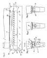
- the example of the intermediate dye dryer 19is in the FIG. 2 a structure shown how it can be found in a printing press according to the invention.
- the counter-pressure cylinder 7(as an example of any kind of guide element) and the material web 4 are also indicated.
- the arrow 24stands for the transport direction of the supply air.
- Thisis supplied to the insert 27 via the connecting piece 25, which is fastened in a lateral wall of the housing 26.
- This insertfurther comprises a nozzle bar 28, which extends at least over the width of the material web 4, but whose nozzle width, seen in the direction of the material web, is getting narrower.
- an ultrasonic generating unit 33which is supported on the rear wall of the insert 27 via a support element, such as a support plate 34.
- This ultrasound generating unit 33may carry on its front side facing the material web a membrane or another elastic element in order to increase the influence range of the ultrasound generating unit.
- Below this membrane strip-shaped one or more piezoelectric crystalsare arranged, which are connected to unillustrated electrical leads. Applying an electrical voltage leads to a change in the dimension of a piezoelectric crystal. In this way, an AC electrical voltage can result in a mechanical vibration which, when transmitted to the diaphragm, can cause ambient air to vibrate.
- the described details of the ultrasonic generating device 33are in the FIG. 2 Not shown.
- coilsIn place of piezocrystals can also occur coils, as they are known from speakers. By applying alternating voltages, magnetic fields can be generated by means of such coils, which interact with the magnetic field of one or more magnets and set the coil in motion. If the coil is attached to the membrane, then this is also moved. A suitable control of the coil can lead to a vibrating movement of the coil. Thus, the basic blowing speed of the supply air can also be modulated in this way. Other types of change in the Grundblas Anlagen the supply air are conceivable, without being explained in detail. Thus, other types are known to stimulate membranes like a loudspeaker to vibrate.
- FIG. 3shows the view III-III of FIG. 2 , With the concentric arcs representing wavy lines 35, here is a sound wave symbolizes. Evident is still the narrowing cross-section of the nozzle bar 28th
- FIG. 4shows a modification of the in FIG. 3 shown embodiment of the invention.
- the cross-section of the nozzle bar 28is not symmetrical to the radial direction of the impression cylinder constructed, but shows slightly against the transport direction of the web, so that the gas jet blows partially against the transport direction and thus increases the relative gas velocity.
- the laminar boundary layercan be disturbed more effectively and the degree of turbulence can be increased. A better transfer of the solvent into the gas jet is achieved.
- FIG. 5shows a further embodiment of the invention.
- the ultrasonic generating device 33is arranged laterally on the nozzle bar 28 and thus does not disturb the gas jet on the way to the material web.
- the FIG. 6shows a further possibility to realize a printing press according to the invention.
- the ultrasonic generating device 40 shown hereoperates on the principle of a whistle. A portion 30 'of the gas jet passes through the inlet region 41 at high speed on the tongue 42. This device vibrates and also excites the air in the gap 43 to vibrations, which affects the gas jet 30, which makes its way to the web with modulated speed continues.
- the ultrasound generating device 40may also extend transversely to the material web 4, which, however, has no or no appreciable influence on the active principle.
- FIGS. 7 and 8show further possibilities of modulating the basic blowing velocity of the supply air 30, which forms a gas jet.
- the exit gap 45is influenced in its width in different ways.
- a rotating body 46is shown, comprising bores or longitudinal slots 47 through which the supply air 30 can enter and exit.
- the supply aironly emerges when the longitudinal slot 47-at least partially-lies above the outlet gap 45. Otherwise it builds up inside of the body 46, an overpressure, which then discharges again. It can come to a periodic build-up and release of the overpressure, which ultimately represents a modulation of the Grundblas Anlagen.
- a baris shown, which can be pushed by a drive in front of the gap 45 or removed from it.
- the drivecan in turn be done for example by a piezoelectric crystal.
- Other drivesare possible, such as an electric motor.
- opening and closing of the outlet gap 45may be periodic.
- FIG. 9shows an advantageous modification of the embodiment, as with the FIG. 6 is shown.
- the ultrasonic generating device 40extends into the outlet tip of the nozzle bar, so that no air flow can flow past the ultrasonic generating device 40. The efficiency can be increased.
Landscapes
- Engineering & Computer Science (AREA)
- Mechanical Engineering (AREA)
- Drying Of Solid Materials (AREA)
- Ink Jet (AREA)
- Coating Apparatus (AREA)
Description
Translated fromGermanDie Erfindung betrifft eine Druckmaschine gemäß Anspruch 1.
In Druckmaschinen, insbesondere in Rotationsdruckmaschinen, wird Material, entweder Bogen oder Bahnen, mit Druckfarbe bedruckt. Die Druckfarbe enthält als wichtigste Bestandteile Farbpigmente und ein Lösungsmittel (oft auch als Nassanteil bezeichnet). Das Lösungsmittel verdampft, während die Farbpigmente auf dem bedruckten Material zurückbleiben. Bevor Bogen gestapelt, Bahnen aufgerollt oder sogar das bedruckte Material in einem weiteren Druck- oder Farbwerk mit einer weiteren Druckfarbe bedruckt wird, sollte die aufgebrachte Farbe getrocknet sein, d. h., ein ausreichender Teil des Lösungsmittels sollte verdampft sein. Um das Trocknen zu beschleunigen, werden Trocknungseinrichtungen eingesetzt, die in der Regel ein Gebläse umfassen, mit welchem das bedruckte Material mit einem Gasstrahl beaufschlagbar ist. Das Gas ist in der Regel Luft. Jedoch können auch andere Gase verwendet werden. Oft ist das Gas in der Trocknungseinrichtung mittels einer Temperiereinrichtung erwärmt worden, um den Stoffübergang der Lösungsmittelmoleküle in den Gasstrom zu erleichtern.In printing machines, especially in rotary printing presses, material, either sheets or sheets, is printed with ink. The most important constituents of the printing ink are color pigments and a solvent (often referred to as the wet component). The solvent evaporates while the color pigments remain on the printed material. Before sheets are stacked, webs rolled up or even the printed material is printed in another printing or inking unit with another ink, the applied ink should be dried, i. that is, a sufficient portion of the solvent should have evaporated. To accelerate the drying, drying devices are used, which generally include a fan, with which the printed material can be acted upon by a gas jet. The gas is usually air. However, other gases may be used. Often, the gas has been heated in the drying device by means of a tempering device in order to facilitate the mass transfer of the solvent molecules into the gas stream.
Ein Problem bei der Trocknung von bedrucktem Material ist allerdings, dass bei dessen Transport am Material Luftmoleküle anhaften bleiben und damit laminare Grenzschichten bilden, die die Ablösung von Lösungsmitteln erschweren.A problem with the drying of printed material, however, is that when it is transported on the material, air molecules remain adherent and thus form laminar boundary layers, which make the detachment of solvents more difficult.
Die Aufgabe der vorliegenden Erfindung ist es daher, eine verbesserte Druckmaschine vorzuschlagen, in der bei der Trocknung des bedruckten Materials die Ablösung beziehungsweise das Verdampfen von Lösungsmitteln erleichtert wird.The object of the present invention is therefore to propose an improved printing machine, in which the drying or the evaporation of solvents is facilitated in the drying of the printed material.
Erfindungsgemäß wird diese Aufgabe durch die Merkmale des Anspruchs 1 gelöst. Demnach ist eine Einrichtung vorgesehen, mit welcher die Grundblasgeschwindigkeit modulierbar ist. Das bedeutet, dass die Grundblasgeschwindigkeit mit dieser Einrichtung zwischen einer Höchstgeschwindigkeit und einer Minimalgeschwindigkeit variierbar ist. Vorteilhafterweise ist mit der genannten Einrichtung der Gasstrahl mit einer Schwingung beaufschlagbar, was zur Folge hat, dass die Geschwindigkeit des Gasstrahls periodisch zwischen der Maximal- und der Minimalgeschwindigkeit variiert. Durch die sich ständig ändernden Luftdrücke ist es möglich, die an dem bedruckten und in der Druckmaschine transportierten Material anhaftenden laminaren Grenzschichten zumindest zum Teil in turbulente Bewegung zu versetzen und diese laminaren Grenzschichten zu verkleinern oder gar ganz aufzulösen. In der Folge kann nun ein verbesserter Wärmeeintrag in das bedruckte Material erfolgen, und/oder der Stoffübergang des Nassanteils von dem bedruckten Material in den Gasstrahl kann verbessert werden. Damit kann pro Zeiteinheit ein höherer Nassanteil vom Material abgeführt werden, womit sich die Trocknungsgeschwindigkeit erhöht. Andererseits kann, wenn die Trocknungsgeschwindigkeit bereits für ausreichend erachtet wird, ein geringerer Energieeinsatz für die Trocknung erfolgen.According to the invention, this object is solved by the features of
Gemäß der Erfindung ist die Einrichtung, mit welcher die Grundblasgeschwindigkeit modulierbar ist, eine Ultraschallerzeugungseinrichtung. Ultraschall vermag es besonders gut, die Luft in Schwingungen zu versetzen, so dass sich die laminaren Grenzschichten ablösen. Ultraschall kann dabei auf vergleichsweise einfache Arten erzeugt werden. Bei Frequenzen von 20 kHz bis 1 GHz spricht man von Ultraschall. Als Schall bezeichnet man longitudinale Wellen, bei denen der Luftdruck variiert. Dabei wird über bekannte Beziehungen die Geschwindigkeit der einzelnen Luftmoleküle ständig verändert.According to the invention, the means by which the basic blowing speed is modulated is an ultrasonic generating device. Ultrasound is particularly good at causing the air to vibrate, causing the laminar boundary layers to detach. Ultrasound can be generated in comparatively simple ways. At frequencies from 20 kHz to 1 GHz one speaks of ultrasound. Sound refers to longitudinal waves in which the air pressure varies. In this case, the speed of the individual air molecules is constantly changing via known relationships.
Weitere Ausführungsbeispiele der Erfindung gehen aus der gegenständlichen Beschreibung und den Ansprüchen hervor.Further embodiments of the invention will become apparent from the description and the claims.
Die einzelnen Figuren zeigen:
- Fig. 1
- Druckmaschine mit Trocknungseinrichtungen
- Fig. 2
- Ansicht II - II aus der
Figur 1 - Fig. 3
- Ansicht III - III aus der
Figur 2 - Fig. 4
- Eine Abwandlung der in der
Fig. 3 gezeigten Ausführungsform - Fig. 5
- Eine weitere Abwandlung der in der
Fig. 3 gezeigten Ausführungsform - Fig. 6
- Weitere Ausführungsform einer erfindungsgemäßen Druckmaschine
- Fig. 7
- Noch eine Ausführungsform einer erfindungsgemäßen Druckmaschine
- Fig. 8
- Eine weitere Ausführungsform einer erfindungsgemäßen Druckmaschine
- Fig. 9
- Vorteilhafte Abwandlung der in
Fig. 6 gezeigten Ausführungsform
- Fig. 1
- Printing machine with drying equipment
- Fig. 2
- View II - II from the
FIG. 1 - Fig. 3
- View III - III from the
FIG. 2 - Fig. 4
- A modification of the in the
Fig. 3 shown embodiment - Fig. 5
- Another modification of the in the
Fig. 3 shown embodiment - Fig. 6
- Further embodiment of a printing press according to the invention
- Fig. 7
- Yet another embodiment of a printing press according to the invention
- Fig. 8
- Another embodiment of a printing press according to the invention
- Fig. 9
- Advantageous modification of in
Fig. 6 shown embodiment
Die Druckmaschine umfasst eine Abwickeleinrichtung 2, in der eine Rolle 3 drehbar gelagert ist, von der die Materialbahn 4 abgezogen werden kann. Die Transportrichtung wird durch den Pfeil 5 angedeutet. Über mehrere Umlenkwalzen und die Anpresswalze 6 wird die Materialbahn zum Gegendruckzylinder 7 geführt und an diesen angelegt. Die Drehrichtung des Gegendruckzylinders 7 ergibt sich aus dem Pfeil 8.The printing machine comprises an unwinding
Dem Gegendruckzylinder 7 zugeordnet sind insgesamt vier Farbwerke 9, 10, 11, 12, die jeweils einen Druckzylinder 13, 14, 15, 16 umfassen, mit welchen das Druckmotiv auf die Materialbahn 4 aufgebracht wird. Die weiteren Komponenten der Farbwerke sind dem Fachmann bekannt und bedürfen daher an dieser Stelle keiner weiteren Beschreibung. Mit jedem Farbwerk wird eine Druckfarbe verarbeitet.Assigned to the
Um nun zu vermeiden, dass ein Farbbestandteil des Druckmotivs im nächsten Farbwerk verschmiert oder anderweitig unbrauchbar wird, ist jeweils zwischen zwei Farbwerken ein so genannter Zwischenfarbwerkstrockner 17, 18, 19 vorgesehen.In order to avoid that a color component of the print motif in the next inking unit is smeared or otherwise unusable, a so-called intermediate
Hinter dem letzten Farbwerk 12 verlässt die Bahn den Gegendruckzylinder und wird durch Führungswalzen in den Trockenkasten 20 geführt, wobei die Führungswalzen so angeordnet sind, dass sie die bedruckte Seite der Materialbahn 4 nicht berühren. Im Trockenkasten 20 wird die Materialbahn soweit getrocknet, dass sie anschließend in der Aufwickeleinrichtung 21 auf einen Wickel 22 aufgewickelt werden kann.Behind the
Der Trockenkasten 20 kann dabei mehrere Blasluftkästen 23 umfassen, die wie die Zwischenfarbwerkstrockner 17, 18, 19 aufgebaut sein können.The
Am Beispiel des Zwischenfarbwerktrockners 19 ist in der
In dem Einsatz befindet sich eine Ultraschallerzeugungseinheit 33, die sich über ein Stützelement, etwa ein Stützblech 34, an der Rückwand des Einsatzes 27 abstützt. Diese Ultraschallerzeugungseinheit 33 kann auf ihrer, der Materialbahn zugewandten Vorderseite eine Membran oder ein anderes elastisches Element tragen, um den Einflussbereich der Ultraschallerzeugungseinheit zu vergrößern. Unterhalb dieser Membran sind leistenförmig ein oder mehrere Piezokristalle angeordnet, die mit nicht dargestellten elektrischen Zuleitungen verbunden sind. Ein Anlegen einer elektrischen Spannung führt zu einer Änderung der Dimension eines Piezokristalls. Auf diese Weise kann eine elektrische Wechselspannung zu einer mechanischen Schwingung führen, die, wenn sie auf die Membran übertragen wird, die Umgebungsluft zu Schwingungen anregen kann. Die beschriebenen Einzelheiten der Ultraschallerzeugungseinrichtung 33 sind in der
An die Stelle von Piezokristallen können auch Spulen treten, wie sie aus Lautsprechern bekannt sind. Durch Anlegen von Wechselspannungen können mittels solcher Spulen magnetische Felder erzeugt werden, die mit dem magnetischen Feld eines oder mehrerer Magneten wechselwirken und die Spule in Bewegung setzen. Ist die Spule an der Membran befestigt, so wird diese ebenfalls bewegt. Eine passende Ansteuerung der Spule kann zu einer schwingenden Bewegung der Spule führen. Somit kann auch auf diese Weise die Grundblasgeschwindigkeit der Zuluft moduliert werden. Weitere Arten der Veränderung der Grundblasgeschwindigkeit der Zuluft sind denkbar, ohne dass sie im Einzelnen erläutert werden. So sind weitere Arten bekannt, Membranen nach Art eines Lautsprechers zu Schwingungen anzuregen.In place of piezocrystals can also occur coils, as they are known from speakers. By applying alternating voltages, magnetic fields can be generated by means of such coils, which interact with the magnetic field of one or more magnets and set the coil in motion. If the coil is attached to the membrane, then this is also moved. A suitable control of the coil can lead to a vibrating movement of the coil. Thus, the basic blowing speed of the supply air can also be modulated in this way. Other types of change in the Grundblasgeschwindigkeit the supply air are conceivable, without being explained in detail. Thus, other types are known to stimulate membranes like a loudspeaker to vibrate.
Die
Die
Die
Die
Die Ausführungsformen der
In der
Auch wenn in der gegenständlichen Beschreibung vornehmlich der Ultraschall als Schall in einem bestimmten Frequenzbereich beschrieben wurde, so ist die Erfindung nicht auf diesen Frequenzbereich beschränkt. Andere Frequenzbereiche sind gleichermaßen denkbar.Although in the subject description primarily the ultrasound has been described as sound in a certain frequency range, so the invention is not limited to this frequency range. Other frequency ranges are equally conceivable.
Die
Claims (5)
- Printing press having at least one drying device (17, 18, 19, 23) for drying a printed material which can be transported within the printing press (1) by way of a transport device, the drying device comprising a fan, in order to load the printed material with a gas jet, with the result that the wet component of the print evaporates and the printed material dries,characterized in that the printing press has an ultrasound generation unit (30, 40) which loads the gas jet with an ultrasonic oscillation before its point of impact on the printed material, with the result that the gas jet continues its path to the printed material at a modulated speed.
- Printing press according to Claim 1, the speed vector of the gas jet at its point of impact on the printed material being substantially perpendicular with respect to the plane of the printed material.
- Printing press according to Claim 1, the speed vector of the gas jet at its point of impact on the printed material being oblique with respect to the plane of the printed material and counter to the transport direction of the printed material.
- Printing press according to one of Claims 1 to 3, the ultrasound generation unit comprising a piezoelectric loudspeaker.
- Printing press according to one of Claims 1 to 4, the ultrasound generation unit comprising an electromagnetic loudspeaker.
Applications Claiming Priority (2)
| Application Number | Priority Date | Filing Date | Title |
|---|---|---|---|
| DE102010028770 | 2010-05-07 | ||
| PCT/EP2011/057092WO2011138350A1 (en) | 2010-05-07 | 2011-05-04 | Printing machine |
Publications (2)
| Publication Number | Publication Date |
|---|---|
| EP2566694A1 EP2566694A1 (en) | 2013-03-13 |
| EP2566694B1true EP2566694B1 (en) | 2014-07-16 |
Family
ID=44201164
Family Applications (1)
| Application Number | Title | Priority Date | Filing Date |
|---|---|---|---|
| EP11719222.9ANot-in-forceEP2566694B1 (en) | 2010-05-07 | 2011-05-04 | Printing machine |
Country Status (3)
| Country | Link |
|---|---|
| EP (1) | EP2566694B1 (en) |
| ES (1) | ES2508522T3 (en) |
| WO (1) | WO2011138350A1 (en) |
Cited By (1)
| Publication number | Priority date | Publication date | Assignee | Title |
|---|---|---|---|---|
| WO2021145863A1 (en)* | 2020-01-14 | 2021-07-22 | Hewlett-Packard Development Company, L.P. | Image formation with ultrasonic liquid removal |
Families Citing this family (3)
| Publication number | Priority date | Publication date | Assignee | Title |
|---|---|---|---|---|
| CN102615934A (en)* | 2012-04-10 | 2012-08-01 | 张玉海 | Bridge type four-colour film flexible printing machine |
| EP3640034A1 (en)* | 2017-10-30 | 2020-04-22 | HP Scitex Ltd | Print agent drying |
| WO2020222806A1 (en)* | 2019-04-30 | 2020-11-05 | Hp Scitex Ltd. | Print agent drying apparatus |
Family Cites Families (3)
| Publication number | Priority date | Publication date | Assignee | Title |
|---|---|---|---|---|
| DE687293C (en)* | 1936-04-25 | 1940-01-26 | Koenig & Bauer Schnellpressfab | Process for drying the paper webs printed in gravure printing machines or the like. |
| SE8006847L (en)* | 1980-10-01 | 1982-04-02 | Svecia Silkscreen Maskiner Ab | DRY PLANT INTENDED TO DRY FROM A PRINTING MACHINE EQUIPPED WITH PRESSURE SUPPLIED MATERIAL |
| US4591517A (en)* | 1984-06-08 | 1986-05-27 | Overly, Inc. | Web dryer with variable ventilation rate |
- 2011
- 2011-05-04EPEP11719222.9Apatent/EP2566694B1/ennot_activeNot-in-force
- 2011-05-04ESES11719222.9Tpatent/ES2508522T3/enactiveActive
- 2011-05-04WOPCT/EP2011/057092patent/WO2011138350A1/enactiveApplication Filing
Cited By (1)
| Publication number | Priority date | Publication date | Assignee | Title |
|---|---|---|---|---|
| WO2021145863A1 (en)* | 2020-01-14 | 2021-07-22 | Hewlett-Packard Development Company, L.P. | Image formation with ultrasonic liquid removal |
Also Published As
| Publication number | Publication date |
|---|---|
| WO2011138350A1 (en) | 2011-11-10 |
| EP2566694A1 (en) | 2013-03-13 |
| ES2508522T3 (en) | 2014-10-16 |
Similar Documents
| Publication | Publication Date | Title |
|---|---|---|
| EP2714409B1 (en) | Printing machine | |
| EP1272709B1 (en) | Application device | |
| EP2566694B1 (en) | Printing machine | |
| DE102011076899A1 (en) | Rotary printing machine, particularly roll rotary printing machine or inkjet printing machine, comprises printing unit and dryer, where printing unit has central cylinder with separate drive motor arranged at central cylinder | |
| DE102019118568A1 (en) | Sheet processing machine with a turning device and method for conveying sheets | |
| EP1179500A2 (en) | Device for producing an air stream in a duplicating machine | |
| DE102019118565A1 (en) | Sheet processing machine and method for conveying sheets | |
| DE102018110824B4 (en) | Process for drying a substrate and air dryer module for carrying out the process and dryer system | |
| DE19836022A1 (en) | Device to dust printed sheets of paper etc. by powder dusting device which is located inside sheet delivery device has charging-up device outside paper delivery device at location | |
| EP1303407B1 (en) | Drying installation within a sheet-fed printing press | |
| WO2007003239A1 (en) | Device and method for the corona treatment of flat material | |
| WO1997025207A1 (en) | Device for powdering printed products | |
| WO2010066224A2 (en) | Method and apparatus for the non-contact application of a uv print varnish onto a print substrate | |
| EP0886579B1 (en) | Device for dusting printed products | |
| EP1120250B1 (en) | Transport system for a printing press | |
| EP1464491A2 (en) | Machine for the rotary sheet printing or for the sheet coating | |
| DE102011005824A1 (en) | Processing machine with a boom for sheet material | |
| EP1285755A1 (en) | Coating machine for finishing printed sheets | |
| DE10032351A1 (en) | Inking mechanism in off-set printer has ultra sound transmitter producing ultrasonic vibrations in exposed surface section carrying wetting agent to atomise same | |
| EP3310552B1 (en) | Method for electrically treating a film and device for said method | |
| EP0907423A1 (en) | Method and device for the metered application of liquids to material webs | |
| DE10357439B4 (en) | Substrate guiding device in a processing machine | |
| DE102019009156A1 (en) | Sheet processing machine and method for conveying sheets | |
| DE102019118566A1 (en) | Sheet processing machine and method for conveying sheets | |
| EP1314557A1 (en) | Method and apparatus for cooling a printed material in a rotary printing machine |
Legal Events
| Date | Code | Title | Description |
|---|---|---|---|
| PUAI | Public reference made under article 153(3) epc to a published international application that has entered the european phase | Free format text:ORIGINAL CODE: 0009012 | |
| 17P | Request for examination filed | Effective date:20121207 | |
| AK | Designated contracting states | Kind code of ref document:A1 Designated state(s):AL AT BE BG CH CY CZ DE DK EE ES FI FR GB GR HR HU IE IS IT LI LT LU LV MC MK MT NL NO PL PT RO RS SE SI SK SM TR | |
| DAX | Request for extension of the european patent (deleted) | ||
| GRAP | Despatch of communication of intention to grant a patent | Free format text:ORIGINAL CODE: EPIDOSNIGR1 | |
| INTG | Intention to grant announced | Effective date:20140124 | |
| GRAS | Grant fee paid | Free format text:ORIGINAL CODE: EPIDOSNIGR3 | |
| GRAA | (expected) grant | Free format text:ORIGINAL CODE: 0009210 | |
| AK | Designated contracting states | Kind code of ref document:B1 Designated state(s):AL AT BE BG CH CY CZ DE DK EE ES FI FR GB GR HR HU IE IS IT LI LT LU LV MC MK MT NL NO PL PT RO RS SE SI SK SM TR | |
| REG | Reference to a national code | Ref country code:GB Ref legal event code:FG4D Free format text:NOT ENGLISH | |
| REG | Reference to a national code | Ref country code:CH Ref legal event code:EP | |
| REG | Reference to a national code | Ref country code:IE Ref legal event code:FG4D Free format text:LANGUAGE OF EP DOCUMENT: GERMAN | |
| REG | Reference to a national code | Ref country code:AT Ref legal event code:REF Ref document number:677357 Country of ref document:AT Kind code of ref document:T Effective date:20140815 | |
| REG | Reference to a national code | Ref country code:DE Ref legal event code:R096 Ref document number:502011003761 Country of ref document:DE Effective date:20140828 | |
| REG | Reference to a national code | Ref country code:ES Ref legal event code:FG2A Ref document number:2508522 Country of ref document:ES Kind code of ref document:T3 Effective date:20141016 | |
| REG | Reference to a national code | Ref country code:NL Ref legal event code:VDEP Effective date:20140716 | |
| REG | Reference to a national code | Ref country code:LT Ref legal event code:MG4D | |
| PG25 | Lapsed in a contracting state [announced via postgrant information from national office to epo] | Ref country code:GR Free format text:LAPSE BECAUSE OF FAILURE TO SUBMIT A TRANSLATION OF THE DESCRIPTION OR TO PAY THE FEE WITHIN THE PRESCRIBED TIME-LIMIT Effective date:20141017 Ref country code:SE Free format text:LAPSE BECAUSE OF FAILURE TO SUBMIT A TRANSLATION OF THE DESCRIPTION OR TO PAY THE FEE WITHIN THE PRESCRIBED TIME-LIMIT Effective date:20140716 Ref country code:BG Free format text:LAPSE BECAUSE OF FAILURE TO SUBMIT A TRANSLATION OF THE DESCRIPTION OR TO PAY THE FEE WITHIN THE PRESCRIBED TIME-LIMIT Effective date:20141016 Ref country code:NO Free format text:LAPSE BECAUSE OF FAILURE TO SUBMIT A TRANSLATION OF THE DESCRIPTION OR TO PAY THE FEE WITHIN THE PRESCRIBED TIME-LIMIT Effective date:20141016 Ref country code:PT Free format text:LAPSE BECAUSE OF FAILURE TO SUBMIT A TRANSLATION OF THE DESCRIPTION OR TO PAY THE FEE WITHIN THE PRESCRIBED TIME-LIMIT Effective date:20141117 Ref country code:LT Free format text:LAPSE BECAUSE OF FAILURE TO SUBMIT A TRANSLATION OF THE DESCRIPTION OR TO PAY THE FEE WITHIN THE PRESCRIBED TIME-LIMIT Effective date:20140716 Ref country code:FI Free format text:LAPSE BECAUSE OF FAILURE TO SUBMIT A TRANSLATION OF THE DESCRIPTION OR TO PAY THE FEE WITHIN THE PRESCRIBED TIME-LIMIT Effective date:20140716 | |
| PG25 | Lapsed in a contracting state [announced via postgrant information from national office to epo] | Ref country code:CY Free format text:LAPSE BECAUSE OF FAILURE TO SUBMIT A TRANSLATION OF THE DESCRIPTION OR TO PAY THE FEE WITHIN THE PRESCRIBED TIME-LIMIT Effective date:20140716 Ref country code:LV Free format text:LAPSE BECAUSE OF FAILURE TO SUBMIT A TRANSLATION OF THE DESCRIPTION OR TO PAY THE FEE WITHIN THE PRESCRIBED TIME-LIMIT Effective date:20140716 Ref country code:NL Free format text:LAPSE BECAUSE OF FAILURE TO SUBMIT A TRANSLATION OF THE DESCRIPTION OR TO PAY THE FEE WITHIN THE PRESCRIBED TIME-LIMIT Effective date:20140716 Ref country code:IS Free format text:LAPSE BECAUSE OF FAILURE TO SUBMIT A TRANSLATION OF THE DESCRIPTION OR TO PAY THE FEE WITHIN THE PRESCRIBED TIME-LIMIT Effective date:20141116 Ref country code:RS Free format text:LAPSE BECAUSE OF FAILURE TO SUBMIT A TRANSLATION OF THE DESCRIPTION OR TO PAY THE FEE WITHIN THE PRESCRIBED TIME-LIMIT Effective date:20140716 Ref country code:PL Free format text:LAPSE BECAUSE OF FAILURE TO SUBMIT A TRANSLATION OF THE DESCRIPTION OR TO PAY THE FEE WITHIN THE PRESCRIBED TIME-LIMIT Effective date:20140716 | |
| REG | Reference to a national code | Ref country code:DE Ref legal event code:R097 Ref document number:502011003761 Country of ref document:DE | |
| PG25 | Lapsed in a contracting state [announced via postgrant information from national office to epo] | Ref country code:CZ Free format text:LAPSE BECAUSE OF FAILURE TO SUBMIT A TRANSLATION OF THE DESCRIPTION OR TO PAY THE FEE WITHIN THE PRESCRIBED TIME-LIMIT Effective date:20140716 Ref country code:RO Free format text:LAPSE BECAUSE OF FAILURE TO SUBMIT A TRANSLATION OF THE DESCRIPTION OR TO PAY THE FEE WITHIN THE PRESCRIBED TIME-LIMIT Effective date:20140716 Ref country code:DK Free format text:LAPSE BECAUSE OF FAILURE TO SUBMIT A TRANSLATION OF THE DESCRIPTION OR TO PAY THE FEE WITHIN THE PRESCRIBED TIME-LIMIT Effective date:20140716 Ref country code:SK Free format text:LAPSE BECAUSE OF FAILURE TO SUBMIT A TRANSLATION OF THE DESCRIPTION OR TO PAY THE FEE WITHIN THE PRESCRIBED TIME-LIMIT Effective date:20140716 Ref country code:EE Free format text:LAPSE BECAUSE OF FAILURE TO SUBMIT A TRANSLATION OF THE DESCRIPTION OR TO PAY THE FEE WITHIN THE PRESCRIBED TIME-LIMIT Effective date:20140716 | |
| PLBE | No opposition filed within time limit | Free format text:ORIGINAL CODE: 0009261 | |
| STAA | Information on the status of an ep patent application or granted ep patent | Free format text:STATUS: NO OPPOSITION FILED WITHIN TIME LIMIT | |
| 26N | No opposition filed | Effective date:20150417 | |
| PG25 | Lapsed in a contracting state [announced via postgrant information from national office to epo] | Ref country code:SI Free format text:LAPSE BECAUSE OF FAILURE TO SUBMIT A TRANSLATION OF THE DESCRIPTION OR TO PAY THE FEE WITHIN THE PRESCRIBED TIME-LIMIT Effective date:20140716 | |
| REG | Reference to a national code | Ref country code:CH Ref legal event code:PL | |
| GBPC | Gb: european patent ceased through non-payment of renewal fee | Effective date:20150504 | |
| PG25 | Lapsed in a contracting state [announced via postgrant information from national office to epo] | Ref country code:CH Free format text:LAPSE BECAUSE OF NON-PAYMENT OF DUE FEES Effective date:20150531 Ref country code:LI Free format text:LAPSE BECAUSE OF NON-PAYMENT OF DUE FEES Effective date:20150531 Ref country code:MC Free format text:LAPSE BECAUSE OF FAILURE TO SUBMIT A TRANSLATION OF THE DESCRIPTION OR TO PAY THE FEE WITHIN THE PRESCRIBED TIME-LIMIT Effective date:20140716 Ref country code:LU Free format text:LAPSE BECAUSE OF FAILURE TO SUBMIT A TRANSLATION OF THE DESCRIPTION OR TO PAY THE FEE WITHIN THE PRESCRIBED TIME-LIMIT Effective date:20150504 | |
| REG | Reference to a national code | Ref country code:IE Ref legal event code:MM4A | |
| REG | Reference to a national code | Ref country code:FR Ref legal event code:ST Effective date:20160129 | |
| PG25 | Lapsed in a contracting state [announced via postgrant information from national office to epo] | Ref country code:IE Free format text:LAPSE BECAUSE OF NON-PAYMENT OF DUE FEES Effective date:20150504 Ref country code:GB Free format text:LAPSE BECAUSE OF NON-PAYMENT OF DUE FEES Effective date:20150504 | |
| PG25 | Lapsed in a contracting state [announced via postgrant information from national office to epo] | Ref country code:FR Free format text:LAPSE BECAUSE OF NON-PAYMENT OF DUE FEES Effective date:20150601 | |
| PG25 | Lapsed in a contracting state [announced via postgrant information from national office to epo] | Ref country code:MT Free format text:LAPSE BECAUSE OF FAILURE TO SUBMIT A TRANSLATION OF THE DESCRIPTION OR TO PAY THE FEE WITHIN THE PRESCRIBED TIME-LIMIT Effective date:20140716 | |
| PG25 | Lapsed in a contracting state [announced via postgrant information from national office to epo] | Ref country code:HU Free format text:LAPSE BECAUSE OF FAILURE TO SUBMIT A TRANSLATION OF THE DESCRIPTION OR TO PAY THE FEE WITHIN THE PRESCRIBED TIME-LIMIT; INVALID AB INITIO Effective date:20110504 Ref country code:SM Free format text:LAPSE BECAUSE OF FAILURE TO SUBMIT A TRANSLATION OF THE DESCRIPTION OR TO PAY THE FEE WITHIN THE PRESCRIBED TIME-LIMIT Effective date:20140716 | |
| REG | Reference to a national code | Ref country code:AT Ref legal event code:MM01 Ref document number:677357 Country of ref document:AT Kind code of ref document:T Effective date:20160504 | |
| PG25 | Lapsed in a contracting state [announced via postgrant information from national office to epo] | Ref country code:HR Free format text:LAPSE BECAUSE OF FAILURE TO SUBMIT A TRANSLATION OF THE DESCRIPTION OR TO PAY THE FEE WITHIN THE PRESCRIBED TIME-LIMIT Effective date:20140716 Ref country code:BE Free format text:LAPSE BECAUSE OF NON-PAYMENT OF DUE FEES Effective date:20150531 | |
| PG25 | Lapsed in a contracting state [announced via postgrant information from national office to epo] | Ref country code:TR Free format text:LAPSE BECAUSE OF FAILURE TO SUBMIT A TRANSLATION OF THE DESCRIPTION OR TO PAY THE FEE WITHIN THE PRESCRIBED TIME-LIMIT Effective date:20140716 Ref country code:AT Free format text:LAPSE BECAUSE OF NON-PAYMENT OF DUE FEES Effective date:20160504 | |
| PG25 | Lapsed in a contracting state [announced via postgrant information from national office to epo] | Ref country code:MK Free format text:LAPSE BECAUSE OF FAILURE TO SUBMIT A TRANSLATION OF THE DESCRIPTION OR TO PAY THE FEE WITHIN THE PRESCRIBED TIME-LIMIT Effective date:20140716 | |
| PG25 | Lapsed in a contracting state [announced via postgrant information from national office to epo] | Ref country code:AL Free format text:LAPSE BECAUSE OF FAILURE TO SUBMIT A TRANSLATION OF THE DESCRIPTION OR TO PAY THE FEE WITHIN THE PRESCRIBED TIME-LIMIT Effective date:20140716 | |
| PGFP | Annual fee paid to national office [announced via postgrant information from national office to epo] | Ref country code:DE Payment date:20200531 Year of fee payment:10 Ref country code:ES Payment date:20200609 Year of fee payment:10 | |
| PGFP | Annual fee paid to national office [announced via postgrant information from national office to epo] | Ref country code:IT Payment date:20200522 Year of fee payment:10 | |
| REG | Reference to a national code | Ref country code:DE Ref legal event code:R119 Ref document number:502011003761 Country of ref document:DE | |
| PG25 | Lapsed in a contracting state [announced via postgrant information from national office to epo] | Ref country code:DE Free format text:LAPSE BECAUSE OF NON-PAYMENT OF DUE FEES Effective date:20211201 | |
| REG | Reference to a national code | Ref country code:ES Ref legal event code:FD2A Effective date:20220801 | |
| PG25 | Lapsed in a contracting state [announced via postgrant information from national office to epo] | Ref country code:ES Free format text:LAPSE BECAUSE OF NON-PAYMENT OF DUE FEES Effective date:20210505 | |
| PG25 | Lapsed in a contracting state [announced via postgrant information from national office to epo] | Ref country code:IT Free format text:LAPSE BECAUSE OF NON-PAYMENT OF DUE FEES Effective date:20200504 | |
| PG25 | Lapsed in a contracting state [announced via postgrant information from national office to epo] | Ref country code:IT Free format text:LAPSE BECAUSE OF NON-PAYMENT OF DUE FEES Effective date:20210504 |