EP2566671B1 - Saw blade with robust tooth form - Google Patents
Saw blade with robust tooth formDownload PDFInfo
- Publication number
- EP2566671B1 EP2566671B1EP11778474.4AEP11778474AEP2566671B1EP 2566671 B1EP2566671 B1EP 2566671B1EP 11778474 AEP11778474 AEP 11778474AEP 2566671 B1EP2566671 B1EP 2566671B1
- Authority
- EP
- European Patent Office
- Prior art keywords
- tooth
- teeth
- unset
- tip
- blade
- Prior art date
- Legal status (The legal status is an assumption and is not a legal conclusion. Google has not performed a legal analysis and makes no representation as to the accuracy of the status listed.)
- Active
Links
Images


Classifications
- B—PERFORMING OPERATIONS; TRANSPORTING
- B23—MACHINE TOOLS; METAL-WORKING NOT OTHERWISE PROVIDED FOR
- B23D—PLANING; SLOTTING; SHEARING; BROACHING; SAWING; FILING; SCRAPING; LIKE OPERATIONS FOR WORKING METAL BY REMOVING MATERIAL, NOT OTHERWISE PROVIDED FOR
- B23D61/00—Tools for sawing machines or sawing devices; Clamping devices for these tools
- B23D61/12—Straight saw blades; Strap saw blades
- B23D61/121—Types of set; Variable teeth, e.g. variable in height or gullet depth; Varying pitch; Details of gullet
- Y—GENERAL TAGGING OF NEW TECHNOLOGICAL DEVELOPMENTS; GENERAL TAGGING OF CROSS-SECTIONAL TECHNOLOGIES SPANNING OVER SEVERAL SECTIONS OF THE IPC; TECHNICAL SUBJECTS COVERED BY FORMER USPC CROSS-REFERENCE ART COLLECTIONS [XRACs] AND DIGESTS
- Y10—TECHNICAL SUBJECTS COVERED BY FORMER USPC
- Y10T—TECHNICAL SUBJECTS COVERED BY FORMER US CLASSIFICATION
- Y10T83/00—Cutting
- Y10T83/929—Tool or tool with support
- Y10T83/9319—Toothed blade or tooth therefor
- Y—GENERAL TAGGING OF NEW TECHNOLOGICAL DEVELOPMENTS; GENERAL TAGGING OF CROSS-SECTIONAL TECHNOLOGIES SPANNING OVER SEVERAL SECTIONS OF THE IPC; TECHNICAL SUBJECTS COVERED BY FORMER USPC CROSS-REFERENCE ART COLLECTIONS [XRACs] AND DIGESTS
- Y10—TECHNICAL SUBJECTS COVERED BY FORMER USPC
- Y10T—TECHNICAL SUBJECTS COVERED BY FORMER US CLASSIFICATION
- Y10T83/00—Cutting
- Y10T83/929—Tool or tool with support
- Y10T83/9454—Reciprocable type
Definitions
- the present inventionrelates to saw blades, and more particularly, to saw blades, such as reciprocating saw or recip blades, with robust tooth forms.
- US2006/0065098discloses a recip blade according to the preamble of claim 1.
- a reciprocating saw machineis a hand-held power saw that includes a chuck for releasably engaging the saw blade and driving the saw blade in a reciprocating motion through a work piece.
- the reciprocating motioncan be an orbital cutting action, a straight or linear cutting action, or an angled cutting action.
- the length or stroke of the reciprocating motionis typically about 1-1/2 inches or less.
- Reciprocating sawsare sometimes referred to as recip saws, jig saws, and power hack saws, and the term reciprocating saw is used herein without limitation to mean reciprocating saw machines, jigsaw machines, and portable power hack machines.
- Reciprocating sawsare typically driven by electric motors (e.g., cord or cordless saws) or are pneumatically driven.
- Well known reciprocating sawsare sold under the brand names "SawzallTM" by Milwaukee Electric Tool Corporation and "Tiger SawTM” by Porter-Cable Corporation.
- a typical reciprocating saw bladeincludes a blade portion having a cutting edge defined by a plurality of teeth axially spaced relative to each other along one side of the blade, and a non-working edge formed on an opposite side of the blade relative to the cutting edge.
- a tang for releasably connecting the blade to the chuck of a reciprocating sawextends from an inner end of the blade.
- the term "recip blade” or “reciprocating saw blade”is used herein to mean a blade configured for use in a reciprocating saw.
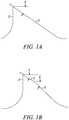
- a typical prior art recip bladeexhibits a tooth form defining a tip 1, a rake face 2 located on one side of the tip, and a clearance surface 3 located on an opposite side of the tip relative to the rake face defining a clearance angle 4.
- the tooth form of FIG. 1Adefines a single or primary clearance surface 3 that runs from the tip of the tooth to the respective gullet radius.
- some such prior art recip bladesdefine relatively steep clearance angles, e.g., about 35° or greater. As a general matter, the steeper the clearance angle, the more sharply pointed is the tooth form, and the faster is the speed of cut.
- Prior art attempts to solve the problem of premature tooth fractureinclude using different set styles wherein multiple teeth are set to the same position to reinforce the teeth of like set position. Although helpful, this feature has not satisfactorily addressed the problem.
- Another attempt to solve the problem of premature tooth fractureinvolves providing the teeth with very low or shallow clearance angles in order to make the teeth wider and more robust.
- a typical such prior art recip bladeis shown in FIG. 1B and exhibits a tooth form defining a tip 1, a rake face 2 located on one side of the tip, a primary clearance surface 3 defining a primary clearance angle 4, and a secondary clearance surface 5 defining a secondary clearance angle 6. As can be seen, the secondary clearance angle 6 is steeper than the primary clearance angle 4.
- a typical such prior art bladedefines a primary clearance angle 4 of about 20° and a secondary clearance angle 6 of about 40°.
- these tooth formsare more - robust in comparison to the tooth forms with relatively steep single clearance angles, such tooth forms tend to develop relatively large wear lands at the junction of the tip 1 and primary clearance surface 3 more quickly than otherwise desired for a given amount of vertical wear of the tooth.
- one of the drawbacks of this type of tooth formis that the teeth tend to cut more slowly and tend to have a shorter life than otherwise desired in applications where tooth breakage is not the dominant mode of failure.
- US 2006/0065098 A1relates to a wood-cutting band saw.
- the present inventionis directed to a recip blade comprising a recip blade body and a cutting edge extending along the recip blade body that includes a plurality of teeth.
- Each of a plurality of the teethincludes a primary clearance surface defining a relatively steep primary clearance angle, a secondary clearance surface defining a relatively shallow secondary clearance angle, a tip, a rake face located on the opposite side of the tip relative to the primary clearance surface, and a gullet.
- the cutting edgeis defined by a repeating pattern of teeth, and at least one tooth of the repeating pattern includes a primary clearance surface defining a relatively steep primary clearance angle and a secondary clearance surface defining a relatively shallow secondary clearance angle.
- the cutting edgeis defined by a repeating pattern including two consecutive teeth, and each of the consecutive teeth includes a primary clearance surface defining a relatively steep primary clearance angle and a secondary clearance surface defining a relatively shallow secondary clearance angle.
- each of the two consecutive teethfurther includes a first gullet radius located on an opposite side of the gullet relative to the rake face, and a second gullet radius located between the gullet and the rake face, wherein the depth of the gullet is greater than the second gullet radius.
- the second gullet radiusis greater than the first gullet radius, each primary clearance angle is within the range of about 25° to about 45°, and each secondary clearance angle is within the range of about 15° to about 25°.
- the rake facepreferably defines a depth that is within the range of about 20% to about 60% of the preceding gullet depth, and more preferably defines a depth that is within the range of about 30% to about 50% of the preceding gullet depth.
- the primary clearance surfacepreferably defines a depth that is within the range of about 10% to about 45% of the succeeding gullet depth, and more preferably is within the range of about 15% to about 40% of the succeeding gullet depth.
- the present inventionis particularly suitable for use in connection with recip blades defining a pitch equal to about 14 pitch or coarser.
- one of the two teeth of the repeating patterndefines a steeper primary clearance angle than the other, and a more shallow secondary clearance angle than the other.
- the tooth defining the steeper primary clearance angle and more shallow secondary clearance angledefines a lower height than the other tooth.
- the difference in height between the two teeth prior to tooth setpreferably is within the range of about 0,051 mm [0.002 inch] to about 0,254 mm [0.010 inch], and more preferably is within the range of about 0,076 mm [0.003 inch] to about 0,127 mm [0.005 inch].
- the repeating pattern including two consecutive teethdefines a plurality of set teeth including at least one first set tooth set to a first set direction, and at least one second set tooth set to a second set direction opposite the first set direction. In some such embodiments, the repeating pattern including two consecutive teeth further defines at least one relatively light first set tooth set to a relatively light first set magnitude, at least one relatively heavy first set tooth set to a relatively heavy first set magnitude, at least one relatively light second set tooth set to a relatively light second set magnitude, and at least one relatively heavy second set tooth set to a relatively heavy second set magnitude.
- the repeating patterndefines a leading light first set tooth, a heavy first set tooth trailing the light first set tooth, a light second set tooth trailing the heavy first set tooth, and a heavy second set tooth trailing the light second set tooth.
- the tips of the heavy set teethare lower than the tips of the light set teeth.
- the repeating patternfurther defines at least one unset tooth.
- the repeating patterndefines a leading light first set tooth, a heavy first set tooth trailing the light first set tooth, a pair of consecutive unset teeth trailing the pair of first set teeth, a light second set tooth trailing the pair of unset teeth, and a heavy second set tooth trailing the light second set tooth.
- the tips of the 0 heavy set teethare preferably lower than the tips of the light set teeth.
- the repeating pattern including two consecutive teethfurther defines at least one leading unset tooth and at least one trailing set tooth with respect to a cutting direction of the saw blade.
- the at least one trailing set toothincludes a first set tooth set to a first direction, and a second set tooth set to a second direction opposite the first direction.
- the repeating patternfurther defines a leading first unset tooth, a first set tooth trailing the leading unset tooth, a second unset tooth trailing the first set tooth, and a second set tooth trailing the second unset tooth.
- the tips of the unset teethare preferably higher than the tips of the set teeth.
- the repeating pattern including the consecutive teethincludes a first pair of consecutive leading teeth set in a first direction, and a second pair of consecutive trailing teeth set in a second direction opposite the first direction.
- the first pairincludes a relatively light set tooth followed by a relatively heavy set tooth
- the second pairincludes a relatively light set tooth followed by a relatively heavy set tooth.
- the repeating patternfurther includes a pair of consecutive unset teeth located between the first and second pairs of teeth.
- the tip of each leading tooth in each pair of consecutive teethis higher than the tip of each trailing tooth in each pair of consecutive teeth.
- the repeating patternis defined by repeating pairs of the two consecutive teeth without any other teeth located therebetween.
- each toothdefines a tertiary clearance surface defining a tertiary clearance angle, and each tertiary clearance angle is greater than the respective secondary clearance angle.
- each toothdefines a tertiary clearance angle that is greater than the respective primary clearance angle, and a primary clearance angle that is greater than the respective secondary clearance angle.
- the recip bladeincludes a tang formed at one end of the blade and a tip formed at an opposite end of the blade relative to the tang.
- the cutting edgefurther defines an unset tooth located at the tip and defining a clearance surface forming the tip, and at least one of (i) at least one relatively short tooth located between the unset tip tooth and the other teeth, and (ii) at least one additional unset tooth located between the unset tip tooth and the other teeth.
- the cutting edgedefines two relatively short consecutive teeth located between the relatively tall unset tip tooth and the repeating pattern of two consecutive teeth.
- each of the two relatively short teethis either unset or defines a light set.
- the at least one relatively short toothis about 30% to about 90% shorter than the unset tip tooth.
- the present inventionis directed to a recip blade comprising a recip blade body and a cutting edge extending along the blade body and including a plurality of teeth.
- Each of a plurality of the teethincludes a tip, a rake face located on one side of the tip, a gullet located on an opposite side of the rake face relative to the tip, first means located on an opposite side of the tip relative to the rake face for imparting cutting speed to the tooth and defining a first clearance angle, and second means located on an opposite side of the first means relative to the tip for imparting toughness to the tooth and defining a secondary clearance angle that is less than the first clearance angle.
- each of the teeth including the first and second meansfurther includes a first gullet radius located on an opposite side of the gullet relative to the rake face, and a second gullet radius located between the gullet and the rake face that is less than the depth of the gullet.
- the first clearance angleis within the range of about 25° to about 45°
- the secondary clearance angleis within the range of about 15° to about 25°
- the rake facedefines a depth that is within the range of about 20% to about 60% of the preceding gullet depth.
- the cutting edgeincludes a repeating pattern defined by repeating pairs of two consecutive teeth without any other teeth located therebetween. One tooth of each pair defines a first clearance angle that is greater than the first clearance angle of the other tooth of the pair, a secondary clearance angle that is less than the secondary clearance angle of the other tooth of the pair, and a tip that is lower than the tip of the other tooth of the pair.
- the first meansis a primary clearance surface
- the second meansis a secondary clearance surface.
- the present inventionis directed to a recip blade comprising a recip blade body and a linear cutting edge extending along the recip blade body and defined by a repeating pattern of two consecutive teeth without any other teeth located therebetween.
- Each of the two consecutive teethincludes a primary clearance surface defining a relatively steep primary clearance angle, a secondary clearance surface defining a relatively shallow secondary clearance angle, a tip, a rake face located on the opposite side of the tip relative to the primary clearance surface, and a gullet.
- each of the two consecutive teethfurther includes a first gullet radius located on an opposite side of the gullet relative to the rake face, and a second gullet radius located between the gullet and the rake face, wherein the gullet defines a depth that is greater than the second gullet radius.
- one tooth of each pairdefines a first clearance angle that is greater than the first clearance angle of the other tooth of the pair, a secondary clearance angle that is less than the secondary clearance angle of the other tooth of the pair, and a tip that is lower than the tip of the other tooth of the pair.
- recip blades of the present inventionhave practical applicability in relatively abusive cutting applications, such as in demolition when cutting wood with nails.
- features of the present inventionare particularly suitable for use in connection with recip blades that are relatively coarse, such as 14 pitch and coarser blades (e.g., 14, 10, 8, 6 and other similarly coarse pitches, such as 5/8, 6/10, 6/8 etc.).
- a further advantage of the recip blades of the inventionis that they can withstand large forces encountered in abusive cutting applications, such as demolition applications involving wood with nails, but also can cut well at high speeds and exhibit long life in non-abusive cutting applications.
- a saw blade embodying the present inventionis indicated generally by the reference numeral 10.
- the saw blade 10comprises a blade body 12 and a cutting edge 14 extending along the blade body 12 and defined by a repeating pattern of two consecutive teeth 16, 18.
- Each of the two consecutive teeth 16, 18includes a primary clearance surface 20 defining a relatively steep primary clearance angle 22, a secondary clearance surface 24 defining a relatively shallow secondary clearance angle 26, a tip 28, a rake face 30 located on the opposite side of the tip 28 relative to the primary clearance surface 20, a gullet 32 defining a depth "D1", a first gullet radius "R1" located on an opposite side of the gullet 32 relative to the rake face 30, and a second gullet radius "R2" located between the gullet 32 and the rake face 30.
- each gullet 32is greater than the second gullet radius R2, and the second gullet radius R2 is greater than the first gullet radius R1.
- Each primary clearance angle 22is within the range of about 25° to about 45°
- each secondary clearance angle 26is within the range of about 15° to about 25°.
- Each second tooth 18 of the repeating pattern of two teethdefines a steeper primary clearance angle 22 than the other, and a more shallow secondary clearance angle 26 than the other.
- each first tooth 16defines a primary clearance angle 22 that is within the range of about 20° to about 30° and a secondary clearance angle 26 that is within the range of about 17° to about 27°
- each second tooth 18defines a primary clearance angle 22 that is within the range of about 30° to about 40° and a secondary clearance angle 26 that is within the range of about 15° to about 25°
- each first tooth 16defines a primary clearance angle 22 of about 25°
- each second tooth 18defines a primary clearance 22 of about 35°, and a secondary clearance angle 26 of about 20°.
- these clearance anglesare only exemplary, and other clearance angles equally may be employed.
- Each rake face 30defines a depth D2 that is within the range of about 20% to about 60% of the preceding gullet depth D1 with respect to the cutting direction of the saw blade, and preferably defines a depth D2 that is within the range of about 30% to about 50% of the preceding gullet depth D1.
- each first tooth 16defines a rake face depth D2 that is greater than the rake face depth D2 of the respective second tooth 18 of the pair.
- the rake face depth D2 of each first tooth 16is about 0,76 mm [0.03 inch]
- the rake face depth D2 of each second tooth 18is about 1,02 mm [0.04 inch].
- Each primary clearance surface 20defines a depth D3 that is preferably within the range of about 10% to about 45% of the succeeding gullet depth D1 with respect to the cutting direction of the saw blade, and more preferably is within the range of about 15% to about 40% of the gullet depth D1.
- the primary clearance surfaces 20 of the first and second teeth 16, 18define approximately the same primary clearance surface depth D3.
- the primary clearance surface depthrD3is preferably within the range of about 0,127 [0.005] to about 1,016 mm [0.040 inch], and in the illustrated embodiment, D3 is about 1/2 mm [1/50 inch].
- the gullet depth D1 of each first tooth 16is greater than the gullet depth of each second tooth. 18.
- the gullet depth of each first tooth 16is about 2,29 mm [0.09 inch], and the gullet depth of each second tooth 18 is about 2,03 mm[0.08 inch].
- the rake face and clearance surface depths disclosed hereinare only exemplary and other depths equally may be employed.
- each second tooth 18 defining the steeper primary clearance angle 22 and more shallow secondary clearance angle 26defines a lower height than the other tooth prior to any tooth set, i.e., the tip of the second tooth 18 is lower than the tip of the preceding first tooth 16 prior to any tooth set.
- the difference in height " ⁇ h" between the two teeth 16, 18 prior to tooth setis within the range of about 0,051 mm [0.002 inch] to about 0,254 mm [0.010 inch], is preferably within the range of about 0,051 mm [0.002 inch] to about 0,203 mm [0.008 inch], and is more preferably within the range of about 0,076 mm [0.003 inch] to about 0,127 mm [0.005 inch].
- One advantage of the saw blades of the present inventionis that the relatively robust tooth forms permit a relatively large height differential (e.g., up to about 0,254 mm [0.010 inch]) between the teeth which, in turn, allows for faster and more efficient cutting speeds in comparison to blades without such tooth height differentials.
- a relatively large height differentiale.g., up to about 0,254 mm [0.010 inch]
- the tooth forms of the inventionsubstantially prevent premature tooth fracture under such increased cutting forces.
- each tooth 16, 18defines a tertiary clearance surface 34 defining a tertiary clearance angle 36.
- Each tertiary clearance angle 36is greater than the respective secondary clearance angle 26.
- each tooth 16, 18defines a tertiary clearance angle 36 that is greater than the respective primary clearance angle 22, and a primary clearance angle 22 that is greater than the respective secondary clearance angle 26.
- the tertiary clearance angles 36 of the first and second teeth 16, 18are approximately equal to each other.
- the tertiary clearance angles 36are preferably within the range of about 40° to about 50°, and in the illustrated embodiment, each tertiary clearance angle is about 45°. As may be recognized by those of ordinary skill in the pertinent art based on the teachings herein, these clearance angles are only exemplary and other clearance angles equally may be employed.
- the saw bladeis a recip blade defining a linear cutting edge.
- the "attack angle” or “tang angle”is preferably within the range of about 3° to about 7°.
- One advantage of this featureis that it causes the teeth of the blade to enter the work piece at an angle different than that otherwise defined by the plane of the tooth tips (or the plane defined by the tips of the unset teeth). This allows the blade to remain aggressive with deep penetration in the cut for more efficient cutting.
- the robust tooth forms of the inventionpermit such an aggressive tang angle while substantially preventing the premature tooth fracture that otherwise might be associated with such an aggressive tang angle in abusive or other demanding applications.
- the repeating patternis defined by repeating pairs of the two consecutive teeth 16, 18 without any other teeth located therebetween.
- the repeating pattern of two consecutive teeth 16, 18preferably defines a pitch equal to about 14 pitch or coarser, e.g., 14, 10, 8, 6 and other similarly coarse pitches, such as 5/8, 6/10, 6/8, etc.
- These relatively coarse pitchesare particularly suitable for recip blades for cutting wood and/or for demolition applications, such as for cutting nail embedded wood or sheet rock with screws or nails.
- these pitchesare exemplary and other pitches equally may be employed.
- the saw blade 10includes a repeating pattern of two consecutive teeth 16, 18 having a set pattern defined by a plurality of set teeth including at least one first set tooth set to a first set direction, such as the "left" set direction, and at least one second set tooth set to a second set direction opposite the first set direction, such as the "right” set direction.
- the "left" set directionis located to the left side of the blade when viewed from the cutting direction of the saw blade
- the "right” set directionis located to the right side of the blade when viewed from the cutting direction of the saw blade.
- the set pattern of the blade 10defines a relatively light first set tooth 16 set to a relatively light first set magnitude (i.e., "light left”), a relatively heavy first set tooth 18 set to a relatively heavy first set magnitude (i.e., "heavy left"), a relatively light second set tooth 16 set to a relatively light second set magnitude (i.e., "light right”), and a relatively heavy second set tooth 18 set to a relatively heavy second set magnitude (i.e., "heavy right”).
- a relatively light first set tooth 16 set to a relatively light first set magnitudei.e., "light left
- a relatively heavy first set tooth 18 set to a relatively heavy first set magnitudei.e., "heavy left
- a relatively light second set tooth 16 set to a relatively light second set magnitudei.e., "light right
- a relatively heavy second set tooth 18 set to a relatively heavy second set magnitudei.e., "heavy right
- the repeating pattern of two consecutive teeth of the saw blade 10has a four tooth set pattern / two tooth mill pattern defined by a leading light first or left set tooth 16, a heavy first or left set tooth 18 trailing the light first or left set tooth, a light second or right set tooth 16 trailing the heavy first or left set tooth, and a heavy second or right set tooth 18 trailing the light second or right set tooth 16.
- the tips of the heavy set teethare lower (designated by the letter “L” for "low”) than the tips of the light set teeth (designated by the letter "H” for "high”).
- FIGS. 5 and 6another embodiment of a saw blade of the present invention is indicated generally by the reference numeral 110.
- the saw blade 110is substantially the same as the saw blade 10 described above with reference to FIGS. 2 through 4 , and therefore like reference numerals preceded by the numeral "1" are used to indicate like elements.
- the tooth forms of the saw blade 110are the same as the saw blade 10, and therefore the illustration of FIG. 2 and the associated detailed description equally apply to the saw blade 110 of FIGS. 5 and 6 .
- the saw blade 110differs from the saw blade 10 with respect to the set pattern.
- the repeating pattern of two consecutive teeth of the saw blade 110further defines a pair of unset teeth. As shown in FIG.
- the repeating pattern of two consecutive teeth of the saw blade 110defines a leading light first or left set tooth 116, a heavy first or left set tooth 118 trailing the light first set tooth, a pair of consecutive unset teeth 116, 118 trailing the pair of first set teeth, a light second or right set tooth 116 trailing the pair of unset teeth, and a heavy second or right set tooth 118 trailing the light second set tooth.
- the tips of the heavy set teethare lower than the tips of the light set teeth.
- FIGS. 7 and 8another embodiment of a saw blade of the present invention is indicated generally by the reference numeral 210.
- the saw blade 210is substantially the same as the saw blades 10 and 110 described above with reference to FIGS. 2 through 6 , and therefore like reference numerals preceded by the numeral "2", or preceded by the numeral "2" instead of the numeral "1", are used to indicate like elements.
- the tooth forms of the saw blade 210are the same as the saw blades 10 and 110 described above in connection with FIGS. 2 through 6 , and therefore the illustration of FIG. 2 and the associated detailed description equally apply to the saw blade 210 of FIGS. 7 and 8 .
- the saw blade 210differs from the saw blades 10 and 110 with respect to the set pattern. As shown in FIG.
- the repeating pattern of two consecutive teeth 216, 218defines a leading first unset tooth 216, a first or right set tooth 218 trailing the leading unset tooth, a second unset tooth 216 trailing the first or right set tooth, and a second or left set tooth 218 trailing the second unset tooth.
- the tips of the unset teeth 216are higher than the tips of the set teeth.
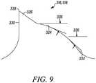
- FIG. 9another embodiment of a tooth form of the invention is indicated generally by the reference numerals 316, 318.
- the tooth form 316, 318is substantially the same as the tooth forms 16, 18 described above in connection with FIG. 2 , and therefore like reference numerals preceded by the numeral "3" are used to indicate like elements.
- the difference of the tooth form 316, 318 in comparison to the tooth forms described aboveis that the secondary and tertiary clearance surfaces 324 and 336 are defined by a curvilinear surface.
- the curvilinear surfaceis defined by one or more radii.
- the secondary clearance angle 326is defined by a tangent to the portion of the curvilinear surface defining the secondary clearance surface 324
- the tertiary clearance angle 336is defined by a tangent to the portion of the curvilinear surface defining the tertiary clearance surface 334.
- this tooth formmay define different dimensions, tooth heights, primary and secondary clearance angles, rake face depths, primary clearance angle depths, and gullet depths, to form the respective first and second teeth 316 and 318, respectively, as described above in connection with FIG. 2 .
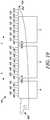
- FIGS. 10-12another embodiment of a saw blade of the present invention is indicated generally by the reference numeral 410.
- the saw blade 410is a recip blade that is configured for plunge cutting.
- One end of the recip blade 410defines a tang 460 for connection to a chuck of a power saw (not shown) and the opposing end defines a tip 450 for puncturing and plunging into a workpiece.
- Cutting teethare arranged on a cutting edge that extends between the tang 460 and the tip 450.
- the teethdefine a cutting direction as indicated by the arrow "x" and a reverse cutting direction as indicated by the arrow "y". As shown in FIGS.
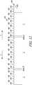
- the cutting teethinclude a repeating pattern of two consecutive set teeth 416, 418 and unset raker teeth 416A/B and 416B/C located between respective series of set teeth 416, 418. More specifically, the cutting edge defines a first series A of three consecutive pairs of set teeth 416, 418, a second series B of six consecutive pairs of set teeth 416, 418, a first unset tooth 416A/B located between the first and second series of set teeth A and B, respectively, a third series C of five consecutive pairs of set teeth 416, 418, a second unset tooth 416 B/C located between the second and third series of set teeth B and C, respectively, a raker tooth 442 contiguous to the tip 450, and a pair of consecutive relatively short teeth 440, 440 located between the third series C of set teeth and the raker tooth 442 at the tip.
- the cutting teeth of the saw blade 410are substantially the same as the saw blades 10 and 110 described above with reference to FIGS. 2 through 6 , and therefore like reference numerals preceded by the numeral "4", or preceded by the numeral "4" instead of the numeral "1", are used to indicate like elements.
- the first teeth 416 and the second teeth 418 of the repeating pattern of two consecutive set teeth, the first unset tooth 416A/B, and the second unset tooth 416B/Care the same tooth forms as the first teeth 16, 116 and second teeth 18, 118 respectively, of the saw blades 10 and 110 described above. Therefore, the illustration of FIG.
- the saw blade 410differs from the saw blades 10 and 110 in that the blade 410 includes the two short teeth 440 and the raker tooth 442 at the tip 450, and two unset teeth 416A/B, 416B/C located between respective series of set teeth.
- the first series A of teethincludes three consecutive pairs of first and second set teeth 416, 418, respectively.
- the set pattern of the first series A of set teethis as follows: a light left tooth 416, a heavy left tooth 418, a light right tooth 416, a heavy right tooth 418, a light left tooth 416, and a heavy left tooth 418.
- the first series A of set teethis followed by the first unset tooth 416A/B which, in turn, is followed by the second series B of set teeth.
- the second series B of set teethincludes six consecutive pairs of first and second set teeth 416, 418, respectively.
- the set pattern of the second series B of set teethis a continuum of the set pattern of the preceding series A of set teeth.
- the set pattern of the second series Bis as follows: a light right tooth 416, a heavy right tooth 418, a light left tooth 416, a heavy left tooth 418, a light right tooth 416, a heavy right tooth 418, a light left tooth 416, a heavy left tooth 418, a light right tooth 416, a heavy right tooth 418, a light left tooth 416, and a heavy left tooth 418.
- the second series B of set teethis followed by the second unset tooth 416B/C which, in turn, is followed by the third series C of set teeth.
- the third series C of set teethincludes five consecutive pairs of first and second set teeth 416, 418, respectively.
- the set pattern of the third series C of set teethis a continuum of the set patterns of the preceding first and second series of set teeth A and B, respectively.
- the set pattern of the third series Cis as follows: a light right tooth .416, a heavy right tooth 418, a light left tooth 416, a heavy left tooth 418, a light right tooth 416, a heavy right tooth 418, alight left tooth 416, a heavy left tooth 418, a light right tooth 416, and a heavy right tooth 418.
- the first, second and third series of set teeth A, B and Crespectively, define a continuous four-tooth repeating set pattern (that is interrupted at the first and second unset teeth 416A/B, 416B/C, respectively) as follows: a light left set tooth, followed by a heavy left set tooth, a light right set tooth, and a heavy right set tooth.
- the unset teeth of the first tooth form 416are positioned along the repeating pattern of consecutive pairs of set teeth 416, 418 at predetermined spaced intervals, such as at about every five centimeters [two inches] of pitch. Accordingly, in such embodiments defining a constant pitch, for example, two or more series of set teeth may include the same number of teeth.
- the lead tooth 416' of the second series B of set teeth and the lead tooth 416" of the third series C of set teetheach defines a second gullet radius R2 that is less than that of all of the other first teeth 416 and second teeth 418 on the blade 410, including that of the first unset tooth 416A/B and the second unset tooth 416B/C.
- the second gullet radius R2 of the lead teeth 416', 416"is about 1/25 inch. As may be recognized by those of ordinary skill in the pertinent art based on the teachings herein, this gullet radius is only exemplary, and other gullet radii equally may be employed.
- each short tooth 440 located between the third series C of set teeth and tip tooth 442defines a single clearance surface 420 that is set at a clearance angle 422 that is greater than the primary clearance angle 422 of the first teeth 416 and substantially the same as the primary clearance angle 422 of the second teeth 418. Accordingly, each clearance angle 422 of the short teeth 440, 440 is within the range of about 30° to about 40°. In the illustrated embodiment, each short tooth 440 defines a primary clearance angle 422 of about 35°. The height of the short teeth 440, 440 limits their set magnitude such that the short teeth 440, 440 are either unset or define a light set.
- the preceding teeth 416, 418 of the third series C of set teeth Care light right set and heavy right set, respectively. Accordingly, consistent with the four-tooth repeating set pattern of the recip blade 410, the two short teeth 440, 440 define a light left set.
- the illustrated number of short teeth and their setare only exemplary.
- the short teethmay be unset, may define a right set, may define different set magnitudes than each other, and/or the blade may include only one short tooth, or may include more than two short teeth.
- the short teeth 440, 440define a lower height than the heights of all of the other teeth on the blade 410, i.e., the tip of each short tooth 440 is lower than the tips of all of the other teeth on the blade 410 prior to any tooth set.
- the short teeth 440, 440are preferably about 30% to about 90% shorter than the unset tip tooth 442.
- the difference in height " ⁇ H2" between the short teeth 440, 440 and both the first teeth 416 and the unset tip or raker tooth 442 prior to any tooth setis within the range of about 0,25 mm [0.01 inch] to about 1,27 mm [0.05 inch], and preferably is within the range of about 0,51 mm [0.02 inch] to about 1,02 mm [0.4 inch].
- the short teeth 440, 440are about 0,76 mm [0.03 inch] shorter than the first teeth 416 and the raker tooth 442 prior to any tooth set. As also shown in FIG.
- the short teeth 440, 440define a rake face depth, D4 that is less than the rake face depth D2 of each of the first teeth 416 and the second teeth 418.
- the rake face depth D4 of the short teeth 440, 440is about 0,711 mm [0.028 inch].
- the short teeth 440, 440also define a first gullet radius R1 that is greater than the first gullet radius R1 of each of the first teeth 416 and the second teeth 418, and a second gullet radius R2 that is less than the second gullet radius R2 of each of the first teeth 416 and the second teeth 418.
- the first gullet radius R1 of the short teeth 440, 440is about 1,143 mm [0.045 inch] and the second gullet radius R2 of the short teeth 440, 440 is about 0,635 mm [0.025 inch].
- the clearance angles, tooth heights, gullet radii and rake face depthsare only exemplary, and other clearance angles, tooth heights, gullet radii and rake face depths equally may be employed.
- the tip or raker tooth 442is unset, is taller than each of the short teeth 440, 440 and the second teeth 418, and is about the same height as the first teeth 416 prior to any tooth set.
- the raker tooth 442includes a single clearance surface 420 that is oriented at a clearance angle 422 that is greater than the clearance angle 422 of the short teeth 440, 440, the primary clearance angle 422 of the first teeth 416, and the primary clearance angle 422 of the second teeth 418.
- the clearance angle 422 of the clearance surface 420 of the raker tooth 442is within the range of about 35° to about 45°.
- the clearance surface 420 of the raker tooth 442defines a primary clearance angle 422 of about 40°.
- the raker tooth 442defines a first gullet radius R1 and a second gullet radius R2 radius that are substantially the same size.
- the first gullet radius R1 and the second gullet radius R2 of the raker tooth 442are also substantially the same size as the first gullet radius R1 of the short teeth 440, 440, i.e., about 0.045 inch.
- the intersection of the clearance surface 420 of the raker tooth 442 and a side edge 452 of the blade 410forms a point or tip 450 that defines the respective end of the blade 410.
- the blade tip 450assists the cut when moving in the reverse cutting direction "y" of the blade, whereas the tip of the raker tooth 442 pierces the workpiece in the plunge cutting direction of the blade, which is substantially normal to the cutting direction "x" and reverse cutting direction "y” of the blade.
- the recip blade 410is particularly advantageous for plunge cutting.
- the tip of the raker tooth 442can be plunged into a work piece to puncture the work piece and create an initial entry point for the blade. After a work piece is punctured by the tip of the raker tooth 442, the blade 410 can be further plunged into the work piece.
- the raker tooth 442is a relatively tall and strong tooth, and therefore creates a pathway within the work piece for the trailing teeth to enter the work piece. As a result, the raker tooth 442 and the short teeth 440 act to protect the first and second set teeth 416, 418, respectively, during a plunge into a work piece.
- the short teeth 440, 440tend stabilize the blade 410 and prevent the blade from veering during plunging.
- the unset raker 442 tooth, the first unset tooth 416A/B, and the second unset tooth 416B/Ccentralize the cutting forces on the blade 410 and thereby substantially prevent the blade from bending or twisting as it is plunged into, and reciprocated through, a work piece. Centralizing the cutting forces on the blade 410 to prevent the blade 410 from bending and/or twisting is especially advantageous because it allows the blade 410 to be relatively long (e.g., at least about 15,2 centimeters [6 inches]), which is required for typical plunge cutting operations.
- the recip bladecan include one ormore additional unset teeth located between the unset tip tooth and the repeating pattern of two consecutive teeth.
- One such embodimentincludes two additional unset teeth located between the unset tip tooth and the repeating pattern of consecutive teeth.
- the additional unset teethare about the same height as the unset tip tooth.
- the additional unset teethare shorter than the unset tip tooth as described above.
- Another advantage of the saw blades of the present inventionis that they can provide significantly improved performance in comparison to prior art saw blades, including improved blade life.
- recip saw blades embodying the inventionwere tested against a prior art blade.
- the blade embodying the inventionwas the same the blade described above in connection with FIGS. 2-4 , and the prior blade is sold by the assignee of the present invention under model no. 656R.
- Both blade typeswere used to cut the same material (1 inch diameter black pipe), at a recip saw speed of about 1000 strokes per minute ("SPM"), under a blade down force of about 25 lbs.
- SPMstrokes per minute
- Each bladewas deemed to have reached its failure mode after either (i) three consecutive cuts averaging 90 seconds, or (ii) one cut above 120 seconds.
- the following test datawas generated: Test No. Recip Blade of Invention Prior Art Recip Blade 1 243 62 2 152 85 3 158 50 4 209 52 5 136 56 Average Results: 179.6 61.0
- the blades embodying the present inventionunexpectedly provide substantially improved blade life (almost three times) in comparison to a comparable prior art blade.
- Another advantage of the blades of the present inventionis that the relatively shallow secondary clearance angle defines a robust tooth form that provides significantly improved resistance to premature tooth facture in abusive cutting applications in comparison to the prior art.
- Yet another advantage of the saw blades of the present inventionis that if the tip of a tooth does fracture, the relatively shallow secondary clearance surface of the same tooth likely will not fracture to thereby permit continued usage of the blade.
- recipor "recip blade(s)” is used herein to mean any saw blade that is designed to cut when driven in a reciprocating motion by a power tool (e.g., in an orbital, linear and/or angled cutting action), including without limitation power tools that are known generally as “reciprocating saws,” such as the SawzallTM sold by Milwaukee Electric Tool Corp and the Tiger SawTM sold by Porter-Cable Corporation, as well as blades utilized in jig saw machines, blades used in air saw machines, and blades used in portable power hack machines.
- a power toole.g., in an orbital, linear and/or angled cutting action
- reciprocating sawssuch as the SawzallTM sold by Milwaukee Electric Tool Corp and the Tiger SawTM sold by Porter-Cable Corporation
- blades utilized in jig saw machinesblades used in air saw machines, and blades used in portable power hack machines.
- the tooth formsmay differ from the tooth forms described herein, certain tooth forms may be removed, other different tooth forms may be added, and/or the teeth of the repeating pattern may all define the same tooth form.
- the bladesmay define different pitches, different set patterns, and different combinations of set patterns and tooth heights than described herein.
- the teethneed not define any height differentials and/or the teeth may define varying degrees of set magnitude (including heavy and light sets as illustrated herein, and other degrees of set).
- any other clearance angles, tooth heights, gullet radii and rake face depths that are known, or that later become known, and different than those described herein equallymay be employed.
- the saw blades described hereinare recip blades, the invention may find applicability to other types of saw blades that are currently known, or that later become known, such as hole saws or hole cutters.
- the blademay include the features described above, but such features may be dimensioned smaller or larger than the dimensions disclosed herein. Accordingly, this detailed description of the currently preferred embodiments is to be taken in an illustrative, as opposed to a limiting sense.
Landscapes
- Engineering & Computer Science (AREA)
- Mechanical Engineering (AREA)
- Milling Processes (AREA)
- Drilling Tools (AREA)
- Sawing (AREA)
- Gear Processing (AREA)
Description
- This application claims priority to co-pending
U.S. Patent Application Serial No. 12/776,145 filed May 7, 2010 - The present invention relates to saw blades, and more particularly, to saw blades, such as reciprocating saw or recip blades, with robust tooth forms.
US2006/0065098 discloses a recip blade according to the preamble of claim 1. - A reciprocating saw machine is a hand-held power saw that includes a chuck for releasably engaging the saw blade and driving the saw blade in a reciprocating motion through a work piece. The reciprocating motion can be an orbital cutting action, a straight or linear cutting action, or an angled cutting action. The length or stroke of the reciprocating motion is typically about 1-1/2 inches or less. Reciprocating saws are sometimes referred to as recip saws, jig saws, and power hack saws, and the term reciprocating saw is used herein without limitation to mean reciprocating saw machines, jigsaw machines, and portable power hack machines. Reciprocating saws are typically driven by electric motors (e.g., cord or cordless saws) or are pneumatically driven. Well known reciprocating saws are sold under the brand names "Sawzall™" by Milwaukee Electric Tool Corporation and "Tiger Saw™" by Porter-Cable Corporation.
- A typical reciprocating saw blade includes a blade portion having a cutting edge defined by a plurality of teeth axially spaced relative to each other along one side of the blade, and a non-working edge formed on an opposite side of the blade relative to the cutting edge. A tang for releasably connecting the blade to the chuck of a reciprocating saw extends from an inner end of the blade. The term "recip blade" or "reciprocating saw blade" is used herein to mean a blade configured for use in a reciprocating saw.
- As shown in
FIG. 1A , a typical prior art recip blade exhibits a tooth form defining a tip 1, arake face 2 located on one side of the tip, and aclearance surface 3 located on an opposite side of the tip relative to the rake face defining aclearance angle 4. The tooth form ofFIG. 1A defines a single orprimary clearance surface 3 that runs from the tip of the tooth to the respective gullet radius. In order to cut faster, some such prior art recip blades define relatively steep clearance angles, e.g., about 35° or greater. As a general matter, the steeper the clearance angle, the more sharply pointed is the tooth form, and the faster is the speed of cut. One drawback associated with such prior art recip blades is that the teeth defining such steep clearance angles are relatively weak, and thus prone to premature fracture, particularly when subjected to abusive cutting applications, such as in demolition where there are interrupted cuts of hard objects that are embedded within softer materials, like nail embedded wood, nail or screw embedded sheetrock, or plaster bonded to metal lath. - Prior art attempts to solve the problem of premature tooth fracture include using different set styles wherein multiple teeth are set to the same position to reinforce the teeth of like set position. Although helpful, this feature has not satisfactorily addressed the problem. Another attempt to solve the problem of premature tooth fracture involves providing the teeth with very low or shallow clearance angles in order to make the teeth wider and more robust. A typical such prior art recip blade is shown in
FIG. 1B and exhibits a tooth form defining a tip 1, arake face 2 located on one side of the tip, aprimary clearance surface 3 defining aprimary clearance angle 4, and asecondary clearance surface 5 defining asecondary clearance angle 6. As can be seen, thesecondary clearance angle 6 is steeper than theprimary clearance angle 4. A typical such prior art blade defines aprimary clearance angle 4 of about 20° and asecondary clearance angle 6 of about 40°. Although these tooth forms are more - robust in comparison to the tooth forms with relatively steep single clearance angles, such tooth forms tend to develop relatively large wear lands at the junction of the tip 1 andprimary clearance surface 3 more quickly than otherwise desired for a given amount of vertical wear of the tooth. As a result, one of the drawbacks of this type of tooth form is that the teeth tend to cut more slowly and tend to have a shorter life than otherwise desired in applications where tooth breakage is not the dominant mode of failure. US 2006/0065098 A1 relates to a wood-cutting band saw.- Accordingly, it is an object of the present invention to overcome one or more of the above-described drawbacks and/or disadvantages of the prior art.
- In accordance with a first aspect, the present invention is directed to a recip blade comprising a recip blade body and a cutting edge extending along the recip blade body that includes a plurality of teeth. Each of a plurality of the teeth includes a primary clearance surface defining a relatively steep primary clearance angle, a secondary clearance surface defining a relatively shallow secondary clearance angle, a tip, a rake face located on the opposite side of the tip relative to the primary clearance surface, and a gullet.
- In the present invention, the cutting edge is defined by a repeating pattern of teeth, and at least one tooth of the repeating pattern includes a primary clearance surface defining a relatively steep primary clearance angle and a secondary clearance surface defining a relatively shallow secondary clearance angle. The cutting edge is defined by a repeating pattern including two consecutive teeth, and each of the consecutive teeth includes a primary clearance surface defining a relatively steep primary clearance angle and a secondary clearance surface defining a relatively shallow secondary clearance angle.
- In currently preferred embodiments of the present invention, each of the two consecutive teeth further includes a first gullet radius located on an opposite side of the gullet relative to the rake face, and a second gullet radius located between the gullet and the rake face, wherein the depth of the gullet is greater than the second gullet radius.
- In currently preferred embodiments of the present invention, the second gullet radius is greater than the first gullet radius, each primary clearance angle is within the range of about 25° to about 45°, and each secondary clearance angle is within the range of about 15° to about 25°. The rake face preferably defines a depth that is within the range of about 20% to about 60% of the preceding gullet depth, and more preferably defines a depth that is within the range of about 30% to about 50% of the preceding gullet depth. The primary clearance surface preferably defines a depth that is within the range of about 10% to about 45% of the succeeding gullet depth, and more preferably is within the range of about 15% to about 40% of the succeeding gullet depth. The present invention is particularly suitable for use in connection with recip blades defining a pitch equal to about 14 pitch or coarser.
- In the present invention, one of the two teeth of the repeating pattern defines a steeper primary clearance angle than the other, and a more shallow secondary clearance angle than the other. In some such embodiments, the tooth defining the steeper primary clearance angle and more shallow secondary clearance angle defines a lower height than the other tooth. The difference in height between the two teeth prior to tooth set preferably is within the range of about 0,051 mm [0.002 inch] to about 0,254 mm [0.010 inch], and more preferably is within the range of about 0,076 mm [0.003 inch] to about 0,127 mm [0.005 inch].
- In some embodiments of the present invention, the repeating pattern including two consecutive teeth defines a plurality of set teeth including at least one first set tooth set to a first set direction, and at least one second set tooth set to a second set direction opposite the first set direction. In some such embodiments, the repeating pattern including two consecutive teeth further defines at least one relatively light first set tooth set to a relatively light first set magnitude, at least one relatively heavy first set tooth set to a relatively heavy first set magnitude, at least one relatively light second set tooth set to a relatively light second set magnitude, and at least one relatively heavy second set tooth set to a relatively heavy second set magnitude. In some such embodiments, the repeating pattern defines a leading light first set tooth, a heavy first set tooth trailing the light first set tooth, a light second set tooth trailing the heavy first set tooth, and a heavy second set tooth trailing the light second set tooth. Preferably, the tips of the heavy set teeth are lower than the tips of the light set teeth. In some such embodiments, the repeating pattern further defines at least one unset tooth. In some such embodiments, the repeating pattern defines a leading light first set tooth, a heavy first set tooth trailing the light first set tooth, a pair of consecutive unset teeth trailing the pair of first set teeth, a light second set tooth trailing the pair of unset teeth, and a heavy second set tooth trailing the light second set tooth. In these embodiments the tips of the 0 heavy set teeth are preferably lower than the tips of the light set teeth.
- In some embodiments of the present invention, the repeating pattern including two consecutive teeth further defines at least one leading unset tooth and at least one trailing set tooth with respect to a cutting direction of the saw blade. In some such embodiments, the at least one trailing set tooth includes a first set tooth set to a first direction, and a second set tooth set to a second direction opposite the first direction. In some such embodiments, the repeating pattern further defines a leading first unset tooth, a first set tooth trailing the leading unset tooth, a second unset tooth trailing the first set tooth, and a second set tooth trailing the second unset tooth. The tips of the unset teeth are preferably higher than the tips of the set teeth.
- In some embodiments of the present invention, the repeating pattern including the consecutive teeth includes a first pair of consecutive leading teeth set in a first direction, and a second pair of consecutive trailing teeth set in a second direction opposite the first direction. In some embodiments of the present invention, the first pair includes a relatively light set tooth followed by a relatively heavy set tooth, and the second pair includes a relatively light set tooth followed by a relatively heavy set tooth. In some such embodiments, the repeating pattern further includes a pair of consecutive unset teeth located between the first and second pairs of teeth. In some such embodiments, the tip of each leading tooth in each pair of consecutive teeth is higher than the tip of each trailing tooth in each pair of consecutive teeth.
- In currently preferred embodiments of the present invention, the repeating pattern is defined by repeating pairs of the two consecutive teeth without any other teeth located therebetween. In addition, each tooth defines a tertiary clearance surface defining a tertiary clearance angle, and each tertiary clearance angle is greater than the respective secondary clearance angle. Preferably, each tooth defines a tertiary clearance angle that is greater than the respective primary clearance angle, and a primary clearance angle that is greater than the respective secondary clearance angle.
- In some currently preferred embodiments of the present invention, the recip blade includes a tang formed at one end of the blade and a tip formed at an opposite end of the blade relative to the tang. The cutting edge further defines an unset tooth located at the tip and defining a clearance surface forming the tip, and at least one of (i) at least one relatively short tooth located between the unset tip tooth and the other teeth, and (ii) at least one additional unset tooth located between the unset tip tooth and the other teeth. In some such embodiments, the cutting edge defines two relatively short consecutive teeth located between the relatively tall unset tip tooth and the repeating pattern of two consecutive teeth. Preferably, each of the two relatively short teeth is either unset or defines a light set. In some such embodiments, the at least one relatively short tooth is about 30% to about 90% shorter than the unset tip tooth.
- In accordance with another aspect, the present invention is directed to a recip blade comprising a recip blade body and a cutting edge extending along the blade body and including a plurality of teeth. Each of a plurality of the teeth includes a tip, a rake face located on one side of the tip, a gullet located on an opposite side of the rake face relative to the tip, first means located on an opposite side of the tip relative to the rake face for imparting cutting speed to the tooth and defining a first clearance angle, and second means located on an opposite side of the first means relative to the tip for imparting toughness to the tooth and defining a secondary clearance angle that is less than the first clearance angle.
- In currently preferred embodiments of the present invention, each of the teeth including the first and second means further includes a first gullet radius located on an opposite side of the gullet relative to the rake face, and a second gullet radius located between the gullet and the rake face that is less than the depth of the gullet.
- In the currently preferred embodiments, the first clearance angle is within the range of about 25° to about 45°, the secondary clearance angle is within the range of about 15° to about 25°, and the rake face defines a depth that is within the range of about 20% to about 60% of the preceding gullet depth. Also in the currently preferred embodiments, the cutting edge includes a repeating pattern defined by repeating pairs of two consecutive teeth without any other teeth located therebetween. One tooth of each pair defines a first clearance angle that is greater than the first clearance angle of the other tooth of the pair, a secondary clearance angle that is less than the secondary clearance angle of the other tooth of the pair, and a tip that is lower than the tip of the other tooth of the pair. Also in the currently preferred embodiments, the first means is a primary clearance surface, and the second means is a secondary clearance surface.
- In accordance with another aspect, the present invention is directed to a recip blade comprising a recip blade body and a linear cutting edge extending along the recip blade body and defined by a repeating pattern of two consecutive teeth without any other teeth located therebetween. Each of the two consecutive teeth includes a primary clearance surface defining a relatively steep primary clearance angle, a secondary clearance surface defining a relatively shallow secondary clearance angle, a tip, a rake face located on the opposite side of the tip relative to the primary clearance surface, and a gullet.
- In currently preferred embodiments of the present invention, each of the two consecutive teeth further includes a first gullet radius located on an opposite side of the gullet relative to the rake face, and a second gullet radius located between the gullet and the rake face, wherein the gullet defines a depth that is greater than the second gullet radius.
- In the currently preferred embodiments of the recip blade, one tooth of each pair defines a first clearance angle that is greater than the first clearance angle of the other tooth of the pair, a secondary clearance angle that is less than the secondary clearance angle of the other tooth of the pair, and a tip that is lower than the tip of the other tooth of the pair.
- One advantage of the recip blades of the present invention is that they have practical applicability in relatively abusive cutting applications, such as in demolition when cutting wood with nails. For example, features of the present invention are particularly suitable for use in connection with recip blades that are relatively coarse, such as 14 pitch and coarser blades (e.g., 14, 10, 8, 6 and other similarly coarse pitches, such as 5/8, 6/10, 6/8 etc.). A further advantage of the recip blades of the invention is that they can withstand large forces encountered in abusive cutting applications, such as demolition applications involving wood with nails, but also can cut well at high speeds and exhibit long life in non-abusive cutting applications. In abusive applications (such as cutting nail embedded wood or sheet rock with screws or nails) some of the tips or primary clearance surfaces of the teeth might break off; however, the relatively shallow secondary clearance surfaces will not fracture and thus permit continued use of the blades. Accordingly, the relatively shallow secondary clearance angles make the teeth less susceptible to catastrophic failure in abusive applications, while the relatively steep primary clearance angles permit fast and efficient cutting.
- Other objects and advantages of the present invention, and/or of the currently preferred embodiments thereof, will become more readily apparent in view of the following detailed description of the currently preferred embodiments and the accompanying drawings.
FIG. 1A is a side elevational view of a prior art recip blade tooth form.FIG. 1B is a side elevational view of another prior art recip blade tooth form.FIG. 2 is partial, side elevational view of a saw blade, such as a recip blade, embodying the present invention.FIG. 3 is a partial, side elevational view of another embodiment of a saw blade of the present invention illustrating a first set pattern.FIG. 4 is a partial, top plan view of the saw blade ofFIG. 3 .FIG. 5 is a partial, side elevational view of another embodiment of a saw blade of the present invention illustrating a second set pattern.FIG. 6 is a partial, top plan view of the saw blade ofFIG. 5 .FIG. 7 is a partial, side elevational view of another embodiment of a saw blade of the present invention illustrating a third set pattern.FIG. 8 is a partial, top plan view of the saw blade ofFIG. 7 .FIG. 9 is a another embodiment of a tooth form of the present invention.FIG. 10 is a side elevational view of another embodiment of a saw blade of the present invention that is configured for plunge cutting.FIG. 11 is a partial, side elevational view of the saw blade ofFIG. 10 illustrating the teeth that are adjacent to the blade's tip.FIG. 12 is a partial, side elevational view of the saw blade ofFIG. 10 illustrating the teeth of the blade.- In
FIG. 2 , a saw blade embodying the present invention is indicated generally by thereference numeral 10. Thesaw blade 10 comprises a blade body 12 and acutting edge 14 extending along the blade body 12 and defined by a repeating pattern of twoconsecutive teeth consecutive teeth primary clearance surface 20 defining a relatively steepprimary clearance angle 22, asecondary clearance surface 24 defining a relatively shallowsecondary clearance angle 26, atip 28, arake face 30 located on the opposite side of thetip 28 relative to theprimary clearance surface 20, agullet 32 defining a depth "D1", a first gullet radius "R1" located on an opposite side of thegullet 32 relative to therake face 30, and a second gullet radius "R2" located between thegullet 32 and therake face 30. - As shown in
FIG, 2 , the depth D1 of eachgullet 32 is greater than the second gullet radius R2, and the second gullet radius R2 is greater than the first gullet radius R1. Eachprimary clearance angle 22 is within the range of about 25° to about 45°, and eachsecondary clearance angle 26 is within the range of about 15° to about 25°. Eachsecond tooth 18 of the repeating pattern of two teeth defines a steeperprimary clearance angle 22 than the other, and a more shallowsecondary clearance angle 26 than the other. Preferably eachfirst tooth 16 defines aprimary clearance angle 22 that is within the range of about 20° to about 30° and asecondary clearance angle 26 that is within the range of about 17° to about 27°, and eachsecond tooth 18 defines aprimary clearance angle 22 that is within the range of about 30° to about 40° and asecondary clearance angle 26 that is within the range of about 15° to about 25°. In the illustrated embodiments, eachfirst tooth 16 defines aprimary clearance angle 22 of about 25°, and asecondary clearance angle 26 of about 22°, and eachsecond tooth 18 defines aprimary clearance 22 of about 35°, and asecondary clearance angle 26 of about 20°. As may be recognized by those of ordinary skill in the pertinent art based on the teachings herein, these clearance angles are only exemplary, and other clearance angles equally may be employed. - Each rake face 30 defines a depth D2 that is within the range of about 20% to about 60% of the preceding gullet depth D1 with respect to the cutting direction of the saw blade, and preferably defines a depth D2 that is within the range of about 30% to about 50% of the preceding gullet depth D1. In addition, each
first tooth 16 defines a rake face depth D2 that is greater than the rake face depth D2 of the respectivesecond tooth 18 of the pair. In the illustrated embodiment, the rake face depth D2 of eachfirst tooth 16 is about 0,76 mm [0.03 inch], and the rake face depth D2 of eachsecond tooth 18 is about 1,02 mm [0.04 inch]. Eachprimary clearance surface 20 defines a depth D3 that is preferably within the range of about 10% to about 45% of the succeeding gullet depth D1 with respect to the cutting direction of the saw blade, and more preferably is within the range of about 15% to about 40% of the gullet depth D1. In the illustrated embodiment, the primary clearance surfaces 20 of the first andsecond teeth FIG. 2 , the gullet depth D1 of eachfirst tooth 16 is greater than the gullet depth of each second tooth. 18. In the illustrated embodiment, the gullet depth of eachfirst tooth 16 is about 2,29 mm [0.09 inch], and the gullet depth of eachsecond tooth 18 is about 2,03 mm[0.08 inch]. As may be recognized by those of ordinary skill in the pertinent art based on the teachings herein, the rake face and clearance surface depths disclosed herein are only exemplary and other depths equally may be employed. - As also shown in
FIG. 2 , eachsecond tooth 18 defining the steeperprimary clearance angle 22 and more shallowsecondary clearance angle 26 defines a lower height than the other tooth prior to any tooth set, i.e., the tip of thesecond tooth 18 is lower than the tip of the precedingfirst tooth 16 prior to any tooth set. The difference in height "Δh" between the twoteeth - As also shown in
FIG. 2 , eachtooth tertiary clearance surface 34 defining atertiary clearance angle 36. Eachtertiary clearance angle 36 is greater than the respectivesecondary clearance angle 26. In the currently preferred embodiments, eachtooth tertiary clearance angle 36 that is greater than the respectiveprimary clearance angle 22, and aprimary clearance angle 22 that is greater than the respectivesecondary clearance angle 26. In the illustrated embodiments, the tertiary clearance angles 36 of the first andsecond teeth - In the currently preferred embodiments of the present invention, the saw blade is a recip blade defining a linear cutting edge. In the currently preferred embodiments of the recip blade, the "attack angle" or "tang angle" is preferably within the range of about 3° to about 7°. One advantage of this feature is that it causes the teeth of the blade to enter the work piece at an angle different than that otherwise defined by the plane of the tooth tips (or the plane defined by the tips of the unset teeth). This allows the blade to remain aggressive with deep penetration in the cut for more efficient cutting. In addition, the robust tooth forms of the invention permit such an aggressive tang angle while substantially preventing the premature tooth fracture that otherwise might be associated with such an aggressive tang angle in abusive or other demanding applications. Also in the currently preferred embodiments, the repeating pattern is defined by repeating pairs of the two
consecutive teeth consecutive teeth - As shown in
FIGS. 3 and 4 , thesaw blade 10 includes a repeating pattern of twoconsecutive teeth FIG. 4 , the "left" set direction is located to the left side of the blade when viewed from the cutting direction of the saw blade, and the "right" set direction is located to the right side of the blade when viewed from the cutting direction of the saw blade. The set pattern of theblade 10 defines a relatively lightfirst set tooth 16 set to a relatively light first set magnitude (i.e., "light left"), a relatively heavyfirst set tooth 18 set to a relatively heavy first set magnitude (i.e., "heavy left"), a relatively lightsecond set tooth 16 set to a relatively light second set magnitude (i.e., "light right"), and a relatively heavysecond set tooth 18 set to a relatively heavy second set magnitude (i.e., "heavy right"). Accordingly, the repeating pattern of two consecutive teeth of thesaw blade 10 has a four tooth set pattern / two tooth mill pattern defined by a leading light first or leftset tooth 16, a heavy first or leftset tooth 18 trailing the light first or left set tooth, a light second orright set tooth 16 trailing the heavy first or left set tooth, and a heavy second orright set tooth 18 trailing the light second orright set tooth 16. As shown inFIG. 3 , the tips of the heavy set teeth are lower (designated by the letter "L" for "low") than the tips of the light set teeth (designated by the letter "H" for "high"). - In
FIGS. 5 and 6 , another embodiment of a saw blade of the present invention is indicated generally by thereference numeral 110. Thesaw blade 110 is substantially the same as thesaw blade 10 described above with reference toFIGS. 2 through 4 , and therefore like reference numerals preceded by the numeral "1" are used to indicate like elements. The tooth forms of thesaw blade 110 are the same as thesaw blade 10, and therefore the illustration ofFIG. 2 and the associated detailed description equally apply to thesaw blade 110 ofFIGS. 5 and 6 . Thesaw blade 110 differs from thesaw blade 10 with respect to the set pattern. The repeating pattern of two consecutive teeth of thesaw blade 110 further defines a pair of unset teeth. As shown inFIG. 6 , the repeating pattern of two consecutive teeth of thesaw blade 110 defines a leading light first or leftset tooth 116, a heavy first or leftset tooth 118 trailing the light first set tooth, a pair of consecutiveunset teeth right set tooth 116 trailing the pair of unset teeth, and a heavy second orright set tooth 118 trailing the light second set tooth. As shown inFIG. 6 , the tips of the heavy set teeth are lower than the tips of the light set teeth. - In
FIGS. 7 and 8 , another embodiment of a saw blade of the present invention is indicated generally by the reference numeral 210. The saw blade 210 is substantially the same as thesaw blades FIGS. 2 through 6 , and therefore like reference numerals preceded by the numeral "2", or preceded by the numeral "2" instead of the numeral "1", are used to indicate like elements. The tooth forms of the saw blade 210 are the same as thesaw blades FIGS. 2 through 6 , and therefore the illustration ofFIG. 2 and the associated detailed description equally apply to the saw blade 210 ofFIGS. 7 and 8 . The saw blade 210 differs from thesaw blades FIG. 8 , the repeating pattern of twoconsecutive teeth unset tooth 216, a first orright set tooth 218 trailing the leading unset tooth, a secondunset tooth 216 trailing the first or right set tooth, and a second or leftset tooth 218 trailing the second unset tooth. As shown inFIG. 7 , the tips of theunset teeth 216 are higher than the tips of the set teeth. - In
FIG. 9 , another embodiment of a tooth form of the invention is indicated generally by the reference numerals 316, 318. The tooth form 316, 318 is substantially the same as the tooth forms 16, 18 described above in connection withFIG. 2 , and therefore like reference numerals preceded by the numeral "3" are used to indicate like elements. The difference of the tooth form 316, 318 in comparison to the tooth forms described above is that the secondary and tertiary clearance surfaces 324 and 336 are defined by a curvilinear surface. The curvilinear surface is defined by one or more radii. Thesecondary clearance angle 326 is defined by a tangent to the portion of the curvilinear surface defining thesecondary clearance surface 324, and thetertiary clearance angle 336 is defined by a tangent to the portion of the curvilinear surface defining thetertiary clearance surface 334. Although only one tooth form is shown inFIG. 9 , this tooth form may define different dimensions, tooth heights, primary and secondary clearance angles, rake face depths, primary clearance angle depths, and gullet depths, to form the respective first and second teeth 316 and 318, respectively, as described above in connection withFIG. 2 . - In
FIGS. 10-12 , another embodiment of a saw blade of the present invention is indicated generally by thereference numeral 410. As shown inFIG. 10 , thesaw blade 410 is a recip blade that is configured for plunge cutting. One end of therecip blade 410 defines atang 460 for connection to a chuck of a power saw (not shown) and the opposing end defines atip 450 for puncturing and plunging into a workpiece. Cutting teeth are arranged on a cutting edge that extends between thetang 460 and thetip 450. The teeth define a cutting direction as indicated by the arrow "x" and a reverse cutting direction as indicated by the arrow "y". As shown inFIGS. 10 and12 , the cutting teeth include a repeating pattern of twoconsecutive set teeth unset raker teeth 416A/B and 416B/C located between respective series of setteeth teeth teeth unset tooth 416A/B located between the first and second series of set teeth A and B, respectively, a third series C of five consecutive pairs of setteeth unset tooth 416 B/C located between the second and third series of set teeth B and C, respectively, araker tooth 442 contiguous to thetip 450, and a pair of consecutive relativelyshort teeth raker tooth 442 at the tip. - The cutting teeth of the
saw blade 410 are substantially the same as thesaw blades FIGS. 2 through 6 , and therefore like reference numerals preceded by the numeral "4", or preceded by the numeral "4" instead of the numeral "1", are used to indicate like elements. Specifically, thefirst teeth 416 and thesecond teeth 418 of the repeating pattern of two consecutive set teeth, the firstunset tooth 416A/B, and the secondunset tooth 416B/C are the same tooth forms as thefirst teeth second teeth saw blades FIG. 2 and the associated detailed description equally apply to thefirst teeth 416, thesecond teeth 418, the firstunset tooth 416A/B and the secondunset tooth 416B/C of thesaw blade 410. As shown inFIGS. 10 and11 and as described above, thesaw blade 410 differs from thesaw blades blade 410 includes the twoshort teeth 440 and theraker tooth 442 at thetip 450, and twounset teeth 416A/B, 416B/C located between respective series of set teeth. - As shown in
FIGS. 10 and12 , the first series A of teeth includes three consecutive pairs of first andsecond set teeth left tooth 416, a heavyleft tooth 418, a lightright tooth 416, a heavyright tooth 418, a lightleft tooth 416, and a heavyleft tooth 418. - The first series A of set teeth is followed by the first
unset tooth 416A/B which, in turn, is followed by the second series B of set teeth. The second series B of set teeth includes six consecutive pairs of first andsecond set teeth right tooth 416, a heavyright tooth 418, a lightleft tooth 416, a heavyleft tooth 418, a lightright tooth 416, a heavyright tooth 418, a lightleft tooth 416, a heavyleft tooth 418, a lightright tooth 416, a heavyright tooth 418, a lightleft tooth 416, and a heavyleft tooth 418. - The second series B of set teeth is followed by the second
unset tooth 416B/C which, in turn, is followed by the third series C of set teeth. The third series C of set teeth includes five consecutive pairs of first andsecond set teeth right tooth 418, a lightleft tooth 416, a heavyleft tooth 418, a lightright tooth 416, a heavyright tooth 418, alightleft tooth 416, a heavyleft tooth 418, a lightright tooth 416, and a heavyright tooth 418. As can be seen, the first, second and third series of set teeth A, B and C, respectively, define a continuous four-tooth repeating set pattern (that is interrupted at the first and secondunset teeth 416A/B, 416B/C, respectively) as follows: a light left set tooth, followed by a heavy left set tooth, a light right set tooth, and a heavy right set tooth. - In an alternative embodiment (not shown), the unset teeth of the
first tooth form 416 are positioned along the repeating pattern of consecutive pairs of setteeth - As shown in
FIG. 12 , the lead tooth 416' of the second series B of set teeth and thelead tooth 416" of the third series C of set teeth each defines a second gullet radius R2 that is less than that of all of the otherfirst teeth 416 andsecond teeth 418 on theblade 410, including that of the firstunset tooth 416A/B and the secondunset tooth 416B/C. In the illustrated embodiment, the second gullet radius R2 of thelead teeth 416', 416" is about 1/25 inch. As may be recognized by those of ordinary skill in the pertinent art based on the teachings herein, this gullet radius is only exemplary, and other gullet radii equally may be employed. - As shown in
FIG. 11 , eachshort tooth 440 located between the third series C of set teeth andtip tooth 442 defines asingle clearance surface 420 that is set at aclearance angle 422 that is greater than theprimary clearance angle 422 of thefirst teeth 416 and substantially the same as theprimary clearance angle 422 of thesecond teeth 418. Accordingly, eachclearance angle 422 of theshort teeth short tooth 440 defines aprimary clearance angle 422 of about 35°. The height of theshort teeth short teeth teeth recip blade 410, the twoshort teeth - As shown in
FIG. 11 , theshort teeth blade 410, i.e., the tip of eachshort tooth 440 is lower than the tips of all of the other teeth on theblade 410 prior to any tooth set. Theshort teeth unset tip tooth 442. The difference in height "ΔH2" between theshort teeth first teeth 416 and the unset tip orraker tooth 442 prior to any tooth set is within the range of about 0,25 mm [0.01 inch] to about 1,27 mm [0.05 inch], and preferably is within the range of about 0,51 mm [0.02 inch] to about 1,02 mm [0.4 inch]. In the illustrated embodiment, theshort teeth first teeth 416 and theraker tooth 442 prior to any tooth set. As also shown inFIG. 1 1 , theshort teeth first teeth 416 and thesecond teeth 418. In the illustrated embodiment, the rake face depth D4 of theshort teeth short teeth first teeth 416 and thesecond teeth 418, and a second gullet radius R2 that is less than the second gullet radius R2 of each of thefirst teeth 416 and thesecond teeth 418. In the illustrated embodiment, the first gullet radius R1 of theshort teeth short teeth
other clearance angles, tooth heights, gullet radii and rake face depths equally may be employed. - As shown best in
FIG. 11 , the tip orraker tooth 442 is unset, is taller than each of theshort teeth second teeth 418, and is about the same height as thefirst teeth 416 prior to any tooth set. Theraker tooth 442 includes asingle clearance surface 420 that is oriented at aclearance angle 422 that is greater than theclearance angle 422 of theshort teeth primary clearance angle 422 of thefirst teeth 416, and theprimary clearance angle 422 of thesecond teeth 418. Theclearance angle 422 of theclearance surface 420 of theraker tooth 442 is within the range of about 35° to about 45°. In the illustrated embodiment, theclearance surface 420 of theraker tooth 442 defines aprimary clearance angle 422 of about 40°. As also shown inFig. 11 , theraker tooth 442 defines a first gullet radius R1 and a second gullet radius R2 radius that are substantially the same size. The first gullet radius R1 and the second gullet radius R2 of theraker tooth 442 are also substantially the same size as the first gullet radius R1 of theshort teeth FIGS. 10-12 , the intersection of theclearance surface 420 of theraker tooth 442 and aside edge 452 of theblade 410 forms a point or tip 450 that defines the respective end of theblade 410. Theblade tip 450 assists the cut when moving in the reverse cutting direction "y" of the blade, whereas the tip of theraker tooth 442 pierces the workpiece in the plunge cutting direction of the blade, which is substantially normal to the cutting direction "x" and reverse cutting direction "y" of the blade. - The
recip blade 410 is particularly advantageous for plunge cutting. The tip of theraker tooth 442 can be plunged into a work piece to puncture the work piece and create an initial entry point for the blade. After a work piece is punctured by the tip of theraker tooth 442, theblade 410 can be further plunged into the work piece. Theraker tooth 442 is a relatively tall and strong tooth, and therefore creates a pathway within the work piece for the trailing teeth to enter the work piece. As a result, theraker tooth 442 and theshort teeth 440 act to protect the first andsecond set teeth short teeth blade 410 and prevent the blade from veering during plunging. Further, theunset raker 442 tooth, the firstunset tooth 416A/B, and the secondunset tooth 416B/C, centralize the cutting forces on theblade 410 and thereby substantially prevent the blade from bending or twisting as it is plunged into, and reciprocated through, a work piece. Centralizing the cutting forces on theblade 410 to prevent theblade 410 from bending and/or twisting is especially advantageous because it allows theblade 410 to be relatively long (e.g., at least about 15,2 centimeters [6 inches]), which is required for typical plunge cutting operations. - In an alternative embodiment of the recip blades, rather than forming one or more relatively short tooth located between the unset tip tooth and the repeating pattern of two consecutive teeth, the recip blade can include one ormore additional unset teeth located between the unset tip tooth and the repeating pattern of two consecutive teeth. One such embodiment includes two additional unset teeth located between the unset tip tooth and the repeating pattern of consecutive teeth. In one such embodiment, the additional unset teeth are about the same height as the unset tip tooth. In another embodiment, the additional unset teeth are shorter than the unset tip tooth as described above.
- Another advantage of the saw blades of the present invention is that they can provide significantly improved performance in comparison to prior art saw blades, including improved blade life. As summarized in the table below, recip saw blades embodying the invention were tested against a prior art blade. The blade embodying the invention was the same the blade described above in connection with
FIGS. 2-4 , and the prior blade is sold by the assignee of the present invention under model no. 656R. Both blade types were used to cut the same material (1 inch diameter black pipe), at a recip saw speed of about 1000 strokes per minute ("SPM"), under a blade down force of about 25 lbs. Each blade was deemed to have reached its failure mode after either (i) three consecutive cuts averaging 90 seconds, or (ii) one cut above 120 seconds. The following test data was generated:Test No. Recip Blade of Invention Prior Art Recip Blade 1 243 62 2 152 85 3 158 50 4 209 52 5 136 56 Average Results: 179.6 61.0 - As can be seen, the blades embodying the present invention unexpectedly provide substantially improved blade life (almost three times) in comparison to a comparable prior art blade. Another advantage of the blades of the present invention is that the relatively shallow secondary clearance angle defines a robust tooth form that provides significantly improved resistance to premature tooth facture in abusive cutting applications in comparison to the prior art. Yet another advantage of the saw blades of the present invention is that if the tip of a tooth does fracture, the relatively shallow secondary clearance surface of the same tooth likely will not fracture to thereby permit continued usage of the blade.
- The term "recip" or "recip blade(s)" is used herein to mean any saw blade that is designed to cut when driven in a reciprocating motion by a power tool (e.g., in an orbital, linear and/or angled cutting action), including without limitation power tools that are known generally as "reciprocating saws," such as the Sawzall™ sold by Milwaukee Electric Tool Corp and the Tiger Saw™ sold by Porter-Cable Corporation, as well as blades utilized in jig saw machines, blades used in air saw machines, and blades used in portable power hack machines.
- As may be recognized by those of ordinary skill in the pertinent art based on the teachings herein, numerous changes and modifications may be made to the above-described and other embodiments of the present invention without departing from the scope of the invention as defined in the appended claims. For example, the tooth forms may differ from the tooth forms described herein, certain tooth forms may be removed, other different tooth forms may be added, and/or the teeth of the repeating pattern may all define the same tooth form. Similarly, the blades may define different pitches, different set patterns, and different combinations of set patterns and tooth heights than described herein. For example, the teeth need not define any height differentials and/or the teeth may define varying degrees of set magnitude (including heavy and light sets as illustrated herein, and other degrees of set). As another example, any other clearance angles, tooth heights, gullet radii and rake face depths that are known, or that later become known, and different than those described herein equally may be employed. In addition, although the saw blades described herein are recip blades, the invention may find applicability to other types of saw blades that are currently known, or that later become known, such as hole saws or hole cutters. As another example, the blade may include the features described above, but such features may be dimensioned smaller or larger than the dimensions disclosed herein. Accordingly, this detailed description of the currently preferred embodiments is to be taken in an illustrative, as opposed to a limiting sense.
Claims (12)
- A recip blade comprising a recip blade body and a cutting edge (14, 452) extending along the recip blade body, wherein the cutting edge (14, 452) includes a plurality of teeth, and each of a plurality of the teeth includes a primary clearance surface (20) defining a relatively steep primary clearance angle (22), a secondary clearance surface (24, 324) defining a relatively shallow secondary clearance angle (26), a tip (28, 328), a rake face (30, 330, 430) located on the opposite side of the tip (28, 328) relative to the primary clearance surface (20), and a gullet (32),characterised in that the cutting edge is defined by a repeating pattern of two consecutive teeth (16, 18, 116, 118, 216, 218, 316, 318, 416, 418), and each tooth of the repeating pattern includes a primary clearance surface (20) defining a relatively steep primary clearance angle (22), a secondary clearance surface (24, 324) defining a relatively shallow secondary clearance angle (26), a tip (28, 328), a rake face (30, 330, 430) located on the opposite side of the tip (28, 328) relative to the primary clearance surface (20), and a gullet (32), wherein one of the two teeth defines a steeper primary clearance angle (22) than the other, and a more shallow secondary clearance angle (26) than the other.
- A recip blade as defined in claim 1, wherein each primary clearance angle (22) is within the range of about 17° to about 45°, and each secondary clearance angle (26) is within the range of about 15° to about 25°.
- A recip blade as defined in claims 1 to 2, wherein each of said teeth further includes a first gullet radius (R1) located on an opposite side of the gullet (32) relative to the rake face (30, 330, 430), and a second gullet radius (R2) located between the gullet (32) and the rake face (30, 330, 430), preferably greater than the first gullet radius (R1), and the gullet (32) defines a depth (D1) that is greater than the second gullet radius (R2).
- A recip blade as defined in claim 1, wherein the rake face defines a depth (D2) that is within the range of about 20% to about 60% of the preceding gullet depth (D1), preferably within the range of about 30% to about 50% of the preceding gullet depth (D1) and/or wherein the primary clearance surface (20) defines a depth (D3) that is within the range of about 10% to about 45% of the succeeding gullet depth (D1), preferably within the range of about 15% to about 40% of the succeeding gullet depth (D1).
- A recip blade as defined in claim 1, wherein one of the two teeth defines either (i) a tip that is lower than the tip of the other or (ii) a lower height than the other, preferably within the range of about 0,051 mm [0.002 inch] to about 0,254 mm [0.010 inch] lower prior to tooth set.
- A recip blade as defined in claim 1, wherein the repeating pattern including two consecutive teeth (16, 18, 116, 118, 216, 218, 316, 318, 416, 418) defines a plurality of set teeth including at least one first set tooth, preferably a first pair of consecutive leading teeth, set to a first set direction and at least one second set tooth, preferably a second pair of consecutive trailing teeth, set to a second set direction opposite the first set direction, wherein particularly the repeating pattern including two consecutive teeth (16, 18, 116, 118, 216, 218, 316, 318, 416, 418) defines at least one relatively light first set tooth, preferably a leading light first set tooth, set to a relatively light first set magnitude, at least one relatively heavy first set tooth, preferably trailing or following the at least one light first set tooth, set to a relatively heavy first set magnitude, at least one relatively light second set tooth, preferably trailing the at least one heavy first set tooth, set to a relatively light second set magnitude, and at least one relatively heavy second set tooth, preferably trailing or following the at least one light second set tooth, set to a relatively heavy second set magnitude.
- A recip blade as defined in claim 6, wherein the repeating pattern including two consecutive teeth (16, 18, 116, 118, 216, 218, 316, 318, 416, 418) further defines at least one unset tooth, preferably an unset leading tooth.
- A recip blade as defined in claim 7, wherein the repeating pattern including two consecutive teeth (16, 18, 116, 118, 216, 218, 316, 318, 416, 418) further defines either (i) a leading light first set tooth, a heavy first set tooth trailing the light first set tooth, a pair of consecutive unset teeth trailing the first set teeth, a light second set tooth trailing the pair of unset teeth, and a heavy second set tooth trailing the light second set tooth or (ii) a leading first unset tooth, a first set tooth trailing the leading unset tooth, a second unset tooth trailing the first set tooth, and a second set tooth trailing the second unset tooth.
- A recip blade as defined in claim 8, wherein (i) the tips of the heavy set teeth are lower than the tips of the light set teeth and/or (ii) the tips of the unset teeth are higher than the tips of a plurality of the set teeth.
- A recip blade as defined in claim 1, wherein the repeating pattern is defined by repeating pairs of the two consecutive teeth (16, 18, 116, 118, 216, 218, 316, 318, 416, 418) without any other teeth located therebetween.
- A recip blade as defined in claim 1, wherein each tooth includes a tertiary clearance surface defined by at least one of a rectilinear and a curvilinear surface, and the tertiary clearance surface defines a tertiary clearance angle (36) that is greater than the respective secondary clearance angle, and preferably greater than the respective primary clearance angle.
- A recip blade as defined in claim 1, further including a tang (460) formed at one end of the blade (410) and a tip (450) formed at an opposite end of the blade relative to the tang (460), wherein the cutting edge further defines an unset tooth (442) located at the tip (450) and defining a clearance surface forming the tip (450), and at least one of (i) at least one relatively short tooth (440), preferably two relatively short consecutive teeth (440), located between the unset tip tooth (442) and the other teeth, wherein, preferably, the at least one relatively short tooth (440) is about 30% to about 90% shorter than the unset tip tooth (442), and (ii) at least one additional unset tooth located between the unset tip tooth (442) and the other teeth.
Applications Claiming Priority (2)
| Application Number | Priority Date | Filing Date | Title |
|---|---|---|---|
| US12/776,145US9375796B2 (en) | 2010-05-07 | 2010-05-07 | Saw blade with robust tooth form |
| PCT/US2011/035660WO2011140533A1 (en) | 2010-05-07 | 2011-05-07 | Saw blade with robust tooth form |
Publications (3)
| Publication Number | Publication Date |
|---|---|
| EP2566671A1 EP2566671A1 (en) | 2013-03-13 |
| EP2566671A4 EP2566671A4 (en) | 2014-12-03 |
| EP2566671B1true EP2566671B1 (en) | 2019-07-03 |
Family
ID=44901041
Family Applications (1)
| Application Number | Title | Priority Date | Filing Date |
|---|---|---|---|
| EP11778474.4AActiveEP2566671B1 (en) | 2010-05-07 | 2011-05-07 | Saw blade with robust tooth form |
Country Status (6)
| Country | Link |
|---|---|
| US (1) | US9375796B2 (en) |
| EP (1) | EP2566671B1 (en) |
| JP (1) | JP5801385B2 (en) |
| AU (1) | AU2011249865B2 (en) |
| CA (1) | CA2798699C (en) |
| WO (1) | WO2011140533A1 (en) |
Cited By (1)
| Publication number | Priority date | Publication date | Assignee | Title |
|---|---|---|---|---|
| US11471963B2 (en) | 2019-01-25 | 2022-10-18 | Black & Decker Inc. | Reciprocating saw blade |
Families Citing this family (26)
| Publication number | Priority date | Publication date | Assignee | Title |
|---|---|---|---|---|
| US10189099B2 (en) | 2010-04-22 | 2019-01-29 | Milwaukee Electric Tool Corporation | Saw Blade |
| EP2564966B1 (en) | 2010-04-22 | 2017-04-12 | Milwaukee Electric Tool Corporation | Saw blade |
| USD841417S1 (en) | 2011-04-22 | 2019-02-26 | Milwaukee Electric Tool Corporation | Saw blade |
| DE102012205041A1 (en)* | 2012-03-29 | 2013-10-02 | Robert Bosch Gmbh | Sawing tool for a machine tool |
| JP5903345B2 (en)* | 2012-07-17 | 2016-04-13 | 株式会社アマダホールディングス | Optimum arrangement method of each tooth of saw blade and saw blade |
| DE112013003582B4 (en) | 2012-07-18 | 2022-08-11 | Milwaukee Electric Tool Corp. | Tooth shape for a cutting tool such as a hole saw |
| CA2845968C (en) | 2013-03-14 | 2016-07-26 | Irwin Industrial Tool Company | Reciprocating saw blade with curved cutting edge |
| US9370834B2 (en)* | 2013-03-14 | 2016-06-21 | Irwin Industrial Tool Company | Saw blade with feed limiter |
| US9662725B2 (en)* | 2013-03-15 | 2017-05-30 | Milwaukee Electric Tool Corporation | Saw blade and system and method for manufacturing a saw blade |
| ITUD20130133A1 (en)* | 2013-10-16 | 2015-04-17 | Gi Esse Salvador S R L | "CUTTING TAPE FOR CUTTING BONES OR MEAT WITH BONES OR MEAT" |
| CN104339422B (en)* | 2014-10-22 | 2016-07-06 | 东莞市益松数控科技有限公司 | Linearly saw and use its processing method and numerically controlled processing equipment |
| US20160158858A1 (en)* | 2014-12-08 | 2016-06-09 | Irwin Industrial Tool Company | Recip blade |
| US10112245B2 (en) | 2015-04-20 | 2018-10-30 | Irwin Industrial Tool Company | Band saw blade |
| US10814414B2 (en) | 2015-11-02 | 2020-10-27 | Milwaukee Electric Tool Corporation | Saw blade |
| US10363619B2 (en) | 2015-11-02 | 2019-07-30 | Black & Decker Inc. | Reciprocating saw blade |
| US10166612B2 (en)* | 2016-08-26 | 2019-01-01 | Irwin Industrial Tool Company | Tooth formations and arrangement for a saw blade |
| US11413693B2 (en)* | 2017-05-16 | 2022-08-16 | Milwaukee Electric Tool Corporation | Saw blade |
| USD835954S1 (en) | 2017-05-16 | 2018-12-18 | Milwaukee Electric Tool Corporation | Saw blade |
| WO2018213413A1 (en) | 2017-05-18 | 2018-11-22 | Milwaukee Electric Tool Corporation | Saw blade and method of manufacturing the same |
| USD835955S1 (en) | 2017-06-08 | 2018-12-18 | Milwaukee Electric Tool Corporation | Saw blade |
| USD835956S1 (en) | 2017-06-15 | 2018-12-18 | Milwaukee Electric Tool Corporation | Saw blade |
| US10537951B2 (en) | 2017-08-16 | 2020-01-21 | Black & Decker Inc. | Band saw blade for cutting structural workpieces |
| US11071255B2 (en) | 2018-03-13 | 2021-07-27 | Deere & Company | Wear resistant precutter knife |
| US11524348B2 (en) | 2019-04-04 | 2022-12-13 | Black & Decker Inc. | Circular saw blade |
| USD948583S1 (en)* | 2019-12-04 | 2022-04-12 | Kapman Ab | Bandsaw blade profile |
| US11700861B2 (en)* | 2021-12-10 | 2023-07-18 | Stéphane Chiasson | Crab processing machine and method, and crab eviscerating disc therefor |
Citations (2)
| Publication number | Priority date | Publication date | Assignee | Title |
|---|---|---|---|---|
| US1390400A (en)* | 1920-08-11 | 1921-09-13 | Alexander Dredden | Combination-tool |
| US5095623A (en)* | 1991-03-21 | 1992-03-17 | William Tennyson | Multipurpose firefighting tool |
Family Cites Families (117)
| Publication number | Priority date | Publication date | Assignee | Title |
|---|---|---|---|---|
| US603128A (en) | 1898-04-26 | Hack-saw | ||
| US820969A (en) | 1905-10-26 | 1906-05-22 | Heinrich Grelck | Saw. |
| US1181529A (en) | 1915-07-26 | 1916-05-02 | Amos Hutton | Saw. |
| US1381930A (en) | 1919-11-24 | 1921-06-21 | Morgan John Henry | Saw for cutting wood, metal, or other substances |
| US1381478A (en) | 1920-11-12 | 1921-06-14 | Austin M Lawrence | Hacksaw-blade |
| US2126382A (en) | 1936-01-27 | 1938-08-09 | Stockton Box Company | Band saw |
| US2227864A (en) | 1938-06-10 | 1941-01-07 | Lerned F Ronan | Metal cutting saw |
| US2241703A (en) | 1939-05-06 | 1941-05-13 | E C Atkins And Company | Hack saw |
| US2394035A (en) | 1943-11-03 | 1946-02-05 | Armstrong Blum Mfg Company | Saw blade |
| US2534424A (en) | 1944-11-17 | 1950-12-19 | Dryden Ernest | Hacksaw blade |
| US2568870A (en) | 1945-10-31 | 1951-09-25 | Lerned F Ronan | Saw |
| US2635327A (en) | 1950-10-07 | 1953-04-21 | Charles C Enlow | Hack saw |
| US2637355A (en) | 1950-11-22 | 1953-05-05 | Borg Warner | Hack saw blade |
| US2682098A (en) | 1952-04-18 | 1954-06-29 | Simonds Saw & Steel Co | Hacksaw |
| US3033251A (en) | 1960-07-07 | 1962-05-08 | Black & Decker Mfg Co | Double edged blades for sabre saw |
| US3028889A (en) | 1960-08-12 | 1962-04-10 | Black & Decker Mfg Co | Offset blades for reciprocating saw |
| US2987086A (en) | 1960-10-04 | 1961-06-06 | Jr Raymond E Westlund | Universal tang for reciprocating saw blade |
| US3111970A (en) | 1961-05-26 | 1963-11-26 | Priest Emmy Lou | Tapered sabre saw blade |
| US3171457A (en) | 1962-06-20 | 1965-03-02 | Lark O Brown | Carcass saw blade |
| US3314456A (en) | 1963-12-10 | 1967-04-18 | Capewell Mfg Company | Reciprocating saw blade with burnishing edge |
| US3292674A (en) | 1964-01-20 | 1966-12-20 | High Duty Saws Ltd | Saws |
| US3357462A (en) | 1964-04-06 | 1967-12-12 | Capewell Mfg Company | Cutting blade |
| US3309756A (en) | 1964-10-30 | 1967-03-21 | North American Products Corp | Circular saw |
| DE1811374B2 (en) | 1968-11-28 | 1973-05-30 | Pahhtzsch, Gotthold, Prof Dr Ing e h , 3300 Braunschweig | CUTTING TOOTH FOR CIRCULAR SAW BLADES OR DISC-SHAPED CUTTERS OF SMALL THICKNESS |
| US3576200A (en) | 1969-02-26 | 1971-04-27 | Heinemann Saw Corp | Circular saw |
| USRE31433E (en) | 1978-08-28 | 1983-11-01 | Capewell Manufacturing Company | Variable tooth saw blade |
| US4179967A (en) | 1978-08-28 | 1979-12-25 | Stanadyne, Inc. | Variable tooth saw blade |
| US4292871A (en) | 1979-02-01 | 1981-10-06 | The L. S. Starrett Company | Welded edge band saw tooth geometry |
| US4232578A (en) | 1979-07-09 | 1980-11-11 | Wallace Murray Corporation | Saw blade and method of making |
| JPS58137520A (en)* | 1982-01-13 | 1983-08-16 | Amada Co Ltd | Band saw blade |
| US4802396A (en) | 1982-06-07 | 1989-02-07 | Kuklinski Anthony K | Saber saw blade |
| FI851660A0 (en) | 1983-08-30 | 1985-04-26 | South Wales Mini Ind Decentral | BANDSAOGBLAD FOER SAOGNING AV TRAEVAROR. |
| CA1277573C (en) | 1985-04-03 | 1990-12-11 | Sumio Yoshida | Saw blade |
| US4784034A (en) | 1985-07-03 | 1988-11-15 | Black & Decker Inc. | Saw blades and saw assemblies |
| US4784033A (en) | 1986-01-22 | 1988-11-15 | Milford Products Corporation | Triple chip ground carbide tip bandsaw blade with ductile filler |
| EP0267311A1 (en) | 1986-11-11 | 1988-05-18 | Black & Decker Inc. | Saw blade for a saw with two saw blades arranged side by side, parallel to each other and oppositely reciprocable |
| US5018421A (en) | 1988-04-07 | 1991-05-28 | Armstrong-Blum Manufacturing Company, Ltd. | Saw blade tooth geometry |
| US4913022A (en) | 1988-05-19 | 1990-04-03 | Kuklinski Anthony K | Circular saw blade |
| CA2004703C (en) | 1988-12-07 | 1998-08-25 | Amada Company, Limited | Saw blade |
| DE9206000U1 (en) | 1992-01-10 | 1992-07-30 | Wilhelm H. Kullmann WIKUS-Sägenfabrik, 3509 Spangenberg | Saw blade |
| US5606900A (en) | 1992-05-11 | 1997-03-04 | The L.S. Starrett Company | Variable height, high performance, bandsaw blade and method of manufacture therefor |
| US5331876A (en) | 1992-07-30 | 1994-07-26 | Sandvik Ab | Saw blade for cutting metal |
| US5477763A (en) | 1993-01-12 | 1995-12-26 | Wikus-Sagenfabrik, Wilhelm H. Kullmann | Saw blade |
| US5340129A (en) | 1993-01-21 | 1994-08-23 | Minnesota Mining And Manufacturing Company | Saw blade retention system |
| US5868058A (en) | 1993-07-22 | 1999-02-09 | Manufacture Forezienne De Lames De Scies S.A. | Log mill band-saw blade for initial processing of timber and derivatives thereof |
| US5410935A (en) | 1993-11-01 | 1995-05-02 | American Saw & Mfg. Company | Band saw blade |
| US5501129A (en)* | 1994-09-27 | 1996-03-26 | Armstrong-Blum Manufacturing Company | All purpose saw blade |
| DE19501019B4 (en) | 1995-01-14 | 2005-11-24 | Scintilla Ag | Saw blade for hand tool machines |
| CN1064877C (en) | 1995-03-08 | 2001-04-25 | 阿曼德有限公司 | Saw blade |
| US6167792B1 (en)* | 1995-03-23 | 2001-01-02 | American Saw & Mfg. Company | Tooth form for a saw blade |
| PL324206A1 (en) | 1995-03-23 | 1998-05-11 | American Saw & Mfg | Synchronised saw teeth of variable design |
| US5603252A (en) | 1995-08-28 | 1997-02-18 | Sandvik Ab | Saw blade |
| DE69717699T2 (en) | 1996-03-11 | 2003-09-18 | Amada Co., Ltd. | band saw blade |
| US5832803A (en) | 1996-08-21 | 1998-11-10 | Sandvik Ab | Tooth structure of a bandsaw blade |
| US5802947A (en) | 1996-10-15 | 1998-09-08 | Credo Tool Company | Dimpled circular saw blade |
| US5848473A (en) | 1997-01-29 | 1998-12-15 | Fiskars Inc. | Saw blade |
| ATE190883T1 (en) | 1997-04-04 | 2000-04-15 | Handschuh & Scheider Gmbh | SAW BLADE |
| DE19820431B4 (en) | 1997-05-08 | 2009-11-19 | Amada Co., Ltd., Isehara | band saw blade |
| USD438549S1 (en) | 1997-05-08 | 2001-03-06 | Amada Company, Limited | Band saw blade |
| JP4464473B2 (en) | 1997-05-08 | 2010-05-19 | 株式会社アマダ | Band saw blade |
| US6439094B1 (en) | 1997-05-15 | 2002-08-27 | Amada Company, Limited | Saw blade |
| SE509398C2 (en) | 1997-06-26 | 1999-01-25 | Sandvik Ab | band saw blades |
| DE19739074B4 (en)* | 1997-09-08 | 2005-07-07 | WIKUS-Sägenfabrik Wilhelm H. Kullmann GmbH & Co. KG | Saw blade and method for its production |
| DE29720605U1 (en) | 1997-11-21 | 1999-03-25 | Scintilla Ag, Solothurn | Saw blade for a, in particular oscillating, sawing machine |
| DE19753952C2 (en) | 1997-12-05 | 2003-06-26 | Stahlwerk Ergste Westig Gmbh | Saw band or blade |
| US6119571A (en) | 1998-04-10 | 2000-09-19 | Sandvik Aktiebolag | Sawblade having unequal spacing between identical tooth groups |
| SE516150C2 (en) | 1998-05-26 | 2001-11-26 | Kapman Ab | Band saw blade for sawing metal |
| US6230411B1 (en) | 1998-07-10 | 2001-05-15 | Porter-Cable Corporation | Blade guide system for a jigsaw |
| US6178646B1 (en) | 1998-07-10 | 2001-01-30 | Porter-Cable Corporation | Blade clamping system for a jigsaw |
| US6357124B1 (en) | 1998-07-10 | 2002-03-19 | Porter-Cable Corporation | Clamp system for a jigsaw tilt base |
| US6883412B1 (en)* | 1998-12-29 | 2005-04-26 | Sheffield Saw & Tool Co., Inc. | Method of fabricating circular saw blades with cutting teeth composed of ultrahard tool material |
| KR20000055341A (en)* | 1999-02-05 | 2000-09-05 | 윤종용 | Control method for intercooler refrigerator |
| EP1034871A3 (en) | 1999-03-11 | 2002-10-02 | Kapman AB | Bandsaw blade having set teeth and exhibiting reduced lateral force |
| JP2001062629A (en) | 1999-06-22 | 2001-03-13 | Amada Co Ltd | Saw edge |
| US6520722B2 (en) | 1999-07-21 | 2003-02-18 | Simonds Industries, Inc. | Asymmetrical cutting tool tooth form |
| US6357122B2 (en) | 1999-08-14 | 2002-03-19 | Vaughan & Bushnell Manufacturing Company | Plunge drywall saw |
| US6276248B1 (en) | 1999-11-05 | 2001-08-21 | American Saw & Manufacturing Company | Band saw blade having reduced noise and uniform tooth loading characteristics |
| DE19963396C2 (en) | 1999-12-28 | 2003-12-04 | Kullmann Wikus Saegenfab | Saw blade with a basic body and unrestricted teeth |
| US6257226B1 (en) | 2000-01-24 | 2001-07-10 | Kapman Ab | Metal-cutting saw having straight and set teeth and method of making |
| JP4610038B2 (en) | 2000-03-17 | 2011-01-12 | 株式会社アマダ | Saw blade |
| US6601495B2 (en)* | 2000-07-18 | 2003-08-05 | American Saw & Mfg. Co., Inc. | Structural saw blade |
| DE10037809A1 (en) | 2000-08-03 | 2002-02-14 | Bosch Gmbh Robert | Saw blade for hand machine tools |
| DE10054296A1 (en) | 2000-11-02 | 2002-05-16 | Kullmann Wikus Saegenfab | Saw band and process for its manufacture |
| JP4133325B2 (en)* | 2000-11-27 | 2008-08-13 | 株式会社アマダ | Saw blade |
| DE10063567A1 (en)* | 2000-12-20 | 2002-07-04 | Scintilla Ag | sawblade |
| US20020184988A1 (en) | 2001-06-12 | 2002-12-12 | Rohman Kenneth J. | Saw blades and methods for manufacturing saw blades |
| US6598509B2 (en) | 2001-06-29 | 2003-07-29 | Simonds Industries, Inc. | Cutting tool tooth form including set teeth with surface features and method of making same |
| US20030010179A1 (en) | 2001-07-16 | 2003-01-16 | Mcluen Carl T. | Splinterless sawblade |
| US7036417B2 (en) | 2001-11-13 | 2006-05-02 | William George Alton | Bandsaw blade with cutting extensions |
| USD482945S1 (en) | 2002-02-28 | 2003-12-02 | Robert Bosch Gmbh | Saw blade |
| US7225715B2 (en)* | 2002-03-19 | 2007-06-05 | Black & Decker Inc. | Variable tooth saw blade |
| US7661347B2 (en) | 2002-10-10 | 2010-02-16 | Amada Company, Limited | Saw blade |
| US20030094078A1 (en)* | 2002-11-01 | 2003-05-22 | Clanton Jon Dennis | Gritted saw blade |
| US20040182218A1 (en)* | 2003-03-21 | 2004-09-23 | Walley Chao | Saw blade |
| JP2004338083A (en) | 2003-04-25 | 2004-12-02 | Kapman Ab | Band saw blade |
| US20040255740A1 (en) | 2003-06-23 | 2004-12-23 | Troyer Daniel C. | Sawdust clearing band saw blade |
| US7131365B2 (en) | 2003-09-16 | 2006-11-07 | Irwin Industrial Tool Company | Multi-chip facet cutting saw blade and related method |
| US7658136B2 (en) | 2004-12-22 | 2010-02-09 | Black & Decker Inc. | Hole saw blade |
| US20050211046A1 (en) | 2004-03-26 | 2005-09-29 | Thomas Rickey J | Tooth form design for reciprocating saw blade |
| US7225714B2 (en) | 2004-12-22 | 2007-06-05 | Black & Decker Inc. | Tooth form design for reciprocating saw blade |
| JP2005305639A (en) | 2004-04-16 | 2005-11-04 | Kapman Ab | Band saw tooth and method of manufacturing band saw tooth |
| US7600458B2 (en) | 2004-04-16 | 2009-10-13 | Irwin Industrial Tool Company | Reciprocating saw blade with tapered tang stem |
| JP4102817B2 (en) | 2004-08-19 | 2008-06-18 | 株式会社アマダ | Band saw blade |
| USD534401S1 (en) | 2004-09-08 | 2007-01-02 | Roger Duffin | Saw blade |
| CA2520545C (en) | 2004-09-22 | 2009-11-24 | Irwin Industrial Tool Company | Saw blade having increased tooth stiffness and resistance to fatigue failure |
| ES2270689B1 (en)* | 2005-01-20 | 2008-03-01 | Instalaciones Inabensa, S.A. | SMOKE SECTOR BARRIER. |
| WO2007098276A2 (en) | 2006-02-25 | 2007-08-30 | James Timothy Cook | Band saw blade |
| US20070199416A1 (en) | 2006-02-25 | 2007-08-30 | Cook James T | Band saw blade |
| US7913601B2 (en) | 2006-04-28 | 2011-03-29 | Simonds International Corporation | Enhanced performance saw blade toothform pattern |
| USD608611S1 (en) | 2007-04-20 | 2010-01-26 | Black & Decker Inc. | Plunge nose reciprocating saw blade |
| US8210081B2 (en)* | 2007-06-12 | 2012-07-03 | Irwin Industrial Tool Company | Reciprocating saw blade having variable-height teeth and related method |
| US9364907B2 (en) | 2007-12-11 | 2016-06-14 | Black & Decker Inc. | Jigsaw blade |
| US20090145280A1 (en) | 2007-12-11 | 2009-06-11 | Black & Decker Inc. | Reciprocating Saw Blade with Plunge Nose |
| DE102008024794A1 (en)* | 2008-05-23 | 2009-11-26 | Robert Röntgen GmbH & Co. KG | Saw band, particularly profiled band, has multiple saw teeth, and tooth groups, which are formed from multiple saw teeth, which replicate in saw cut direction |
| US20090293698A1 (en) | 2008-05-30 | 2009-12-03 | Corona Clipper, Inc. | Saw blade having teeth with varying depths and alternate tip beveling |
| EP2564966B1 (en) | 2010-04-22 | 2017-04-12 | Milwaukee Electric Tool Corporation | Saw blade |
| USD642028S1 (en)* | 2010-05-21 | 2011-07-26 | Irwin Industrial Tool Company | Reciprocating saw blade |
- 2010
- 2010-05-07USUS12/776,145patent/US9375796B2/enactiveActive
- 2011
- 2011-05-07CACA2798699Apatent/CA2798699C/ennot_activeExpired - Fee Related
- 2011-05-07EPEP11778474.4Apatent/EP2566671B1/enactiveActive
- 2011-05-07WOPCT/US2011/035660patent/WO2011140533A1/enactiveApplication Filing
- 2011-05-07AUAU2011249865Apatent/AU2011249865B2/ennot_activeCeased
- 2011-05-07JPJP2013510193Apatent/JP5801385B2/ennot_activeExpired - Fee Related
Patent Citations (2)
| Publication number | Priority date | Publication date | Assignee | Title |
|---|---|---|---|---|
| US1390400A (en)* | 1920-08-11 | 1921-09-13 | Alexander Dredden | Combination-tool |
| US5095623A (en)* | 1991-03-21 | 1992-03-17 | William Tennyson | Multipurpose firefighting tool |
Cited By (1)
| Publication number | Priority date | Publication date | Assignee | Title |
|---|---|---|---|---|
| US11471963B2 (en) | 2019-01-25 | 2022-10-18 | Black & Decker Inc. | Reciprocating saw blade |
Also Published As
| Publication number | Publication date |
|---|---|
| JP2013526421A (en) | 2013-06-24 |
| AU2011249865B2 (en) | 2015-12-03 |
| WO2011140533A1 (en) | 2011-11-10 |
| CA2798699A1 (en) | 2011-11-10 |
| JP5801385B2 (en) | 2015-10-28 |
| CA2798699C (en) | 2015-10-27 |
| US20110271815A1 (en) | 2011-11-10 |
| EP2566671A4 (en) | 2014-12-03 |
| AU2011249865A1 (en) | 2012-11-29 |
| US9375796B2 (en) | 2016-06-28 |
| EP2566671A1 (en) | 2013-03-13 |
Similar Documents
| Publication | Publication Date | Title |
|---|---|---|
| EP2566671B1 (en) | Saw blade with robust tooth form | |
| EP2589018B1 (en) | Reciprocating saw blade | |
| US20240017338A1 (en) | Saw blade | |
| US11203072B2 (en) | Tooth formations and arrangement for a saw blade | |
| US8210081B2 (en) | Reciprocating saw blade having variable-height teeth and related method | |
| AU2013200052B2 (en) | Double-Sided Reciprocating Saw Blade and Related Method | |
| EP3187292A1 (en) | Saw blade | |
| EP2777855B1 (en) | Saw blade with chip-limiters | |
| US6691596B1 (en) | Circular saw blade for cutting fiber cement materials | |
| EP2762255A1 (en) | Double-sided reciprocating saw blade and related method |
Legal Events
| Date | Code | Title | Description |
|---|---|---|---|
| PUAI | Public reference made under article 153(3) epc to a published international application that has entered the european phase | Free format text:ORIGINAL CODE: 0009012 | |
| 17P | Request for examination filed | Effective date:20121207 | |
| AK | Designated contracting states | Kind code of ref document:A1 Designated state(s):AL AT BE BG CH CY CZ DE DK EE ES FI FR GB GR HR HU IE IS IT LI LT LU LV MC MK MT NL NO PL PT RO RS SE SI SK SM TR | |
| DAX | Request for extension of the european patent (deleted) | ||
| A4 | Supplementary search report drawn up and despatched | Effective date:20141103 | |
| RIC1 | Information provided on ipc code assigned before grant | Ipc:B27B 33/02 20060101AFI20141028BHEP Ipc:B23D 61/12 20060101ALI20141028BHEP | |
| STAA | Information on the status of an ep patent application or granted ep patent | Free format text:STATUS: EXAMINATION IS IN PROGRESS | |
| 17Q | First examination report despatched | Effective date:20170704 | |
| GRAP | Despatch of communication of intention to grant a patent | Free format text:ORIGINAL CODE: EPIDOSNIGR1 | |
| STAA | Information on the status of an ep patent application or granted ep patent | Free format text:STATUS: GRANT OF PATENT IS INTENDED | |
| INTG | Intention to grant announced | Effective date:20190129 | |
| RAP1 | Party data changed (applicant data changed or rights of an application transferred) | Owner name:BLACK & DECKER INC. | |
| GRAS | Grant fee paid | Free format text:ORIGINAL CODE: EPIDOSNIGR3 | |
| GRAA | (expected) grant | Free format text:ORIGINAL CODE: 0009210 | |
| STAA | Information on the status of an ep patent application or granted ep patent | Free format text:STATUS: THE PATENT HAS BEEN GRANTED | |
| AK | Designated contracting states | Kind code of ref document:B1 Designated state(s):AL AT BE BG CH CY CZ DE DK EE ES FI FR GB GR HR HU IE IS IT LI LT LU LV MC MK MT NL NO PL PT RO RS SE SI SK SM TR | |
| REG | Reference to a national code | Ref country code:GB Ref legal event code:FG4D | |
| REG | Reference to a national code | Ref country code:CH Ref legal event code:EP Ref country code:AT Ref legal event code:REF Ref document number:1150426 Country of ref document:AT Kind code of ref document:T Effective date:20190715 | |
| REG | Reference to a national code | Ref country code:IE Ref legal event code:FG4D | |
| REG | Reference to a national code | Ref country code:DE Ref legal event code:R096 Ref document number:602011060217 Country of ref document:DE | |
| REG | Reference to a national code | Ref country code:NL Ref legal event code:MP Effective date:20190703 | |
| REG | Reference to a national code | Ref country code:LT Ref legal event code:MG4D | |
| REG | Reference to a national code | Ref country code:AT Ref legal event code:MK05 Ref document number:1150426 Country of ref document:AT Kind code of ref document:T Effective date:20190703 | |
| PG25 | Lapsed in a contracting state [announced via postgrant information from national office to epo] | Ref country code:NL Free format text:LAPSE BECAUSE OF FAILURE TO SUBMIT A TRANSLATION OF THE DESCRIPTION OR TO PAY THE FEE WITHIN THE PRESCRIBED TIME-LIMIT Effective date:20190703 Ref country code:AT Free format text:LAPSE BECAUSE OF FAILURE TO SUBMIT A TRANSLATION OF THE DESCRIPTION OR TO PAY THE FEE WITHIN THE PRESCRIBED TIME-LIMIT Effective date:20190703 Ref country code:PT Free format text:LAPSE BECAUSE OF FAILURE TO SUBMIT A TRANSLATION OF THE DESCRIPTION OR TO PAY THE FEE WITHIN THE PRESCRIBED TIME-LIMIT Effective date:20191104 Ref country code:BG Free format text:LAPSE BECAUSE OF FAILURE TO SUBMIT A TRANSLATION OF THE DESCRIPTION OR TO PAY THE FEE WITHIN THE PRESCRIBED TIME-LIMIT Effective date:20191003 Ref country code:SE Free format text:LAPSE BECAUSE OF FAILURE TO SUBMIT A TRANSLATION OF THE DESCRIPTION OR TO PAY THE FEE WITHIN THE PRESCRIBED TIME-LIMIT Effective date:20190703 Ref country code:LT Free format text:LAPSE BECAUSE OF FAILURE TO SUBMIT A TRANSLATION OF THE DESCRIPTION OR TO PAY THE FEE WITHIN THE PRESCRIBED TIME-LIMIT Effective date:20190703 Ref country code:HR Free format text:LAPSE BECAUSE OF FAILURE TO SUBMIT A TRANSLATION OF THE DESCRIPTION OR TO PAY THE FEE WITHIN THE PRESCRIBED TIME-LIMIT Effective date:20190703 Ref country code:CZ Free format text:LAPSE BECAUSE OF FAILURE TO SUBMIT A TRANSLATION OF THE DESCRIPTION OR TO PAY THE FEE WITHIN THE PRESCRIBED TIME-LIMIT Effective date:20190703 Ref country code:FI Free format text:LAPSE BECAUSE OF FAILURE TO SUBMIT A TRANSLATION OF THE DESCRIPTION OR TO PAY THE FEE WITHIN THE PRESCRIBED TIME-LIMIT Effective date:20190703 Ref country code:NO Free format text:LAPSE BECAUSE OF FAILURE TO SUBMIT A TRANSLATION OF THE DESCRIPTION OR TO PAY THE FEE WITHIN THE PRESCRIBED TIME-LIMIT Effective date:20191003 | |
| PG25 | Lapsed in a contracting state [announced via postgrant information from national office to epo] | Ref country code:LV Free format text:LAPSE BECAUSE OF FAILURE TO SUBMIT A TRANSLATION OF THE DESCRIPTION OR TO PAY THE FEE WITHIN THE PRESCRIBED TIME-LIMIT Effective date:20190703 Ref country code:ES Free format text:LAPSE BECAUSE OF FAILURE TO SUBMIT A TRANSLATION OF THE DESCRIPTION OR TO PAY THE FEE WITHIN THE PRESCRIBED TIME-LIMIT Effective date:20190703 Ref country code:AL Free format text:LAPSE BECAUSE OF FAILURE TO SUBMIT A TRANSLATION OF THE DESCRIPTION OR TO PAY THE FEE WITHIN THE PRESCRIBED TIME-LIMIT Effective date:20190703 Ref country code:IS Free format text:LAPSE BECAUSE OF FAILURE TO SUBMIT A TRANSLATION OF THE DESCRIPTION OR TO PAY THE FEE WITHIN THE PRESCRIBED TIME-LIMIT Effective date:20191103 Ref country code:GR Free format text:LAPSE BECAUSE OF FAILURE TO SUBMIT A TRANSLATION OF THE DESCRIPTION OR TO PAY THE FEE WITHIN THE PRESCRIBED TIME-LIMIT Effective date:20191004 Ref country code:RS Free format text:LAPSE BECAUSE OF FAILURE TO SUBMIT A TRANSLATION OF THE DESCRIPTION OR TO PAY THE FEE WITHIN THE PRESCRIBED TIME-LIMIT Effective date:20190703 | |
| PG25 | Lapsed in a contracting state [announced via postgrant information from national office to epo] | Ref country code:TR Free format text:LAPSE BECAUSE OF FAILURE TO SUBMIT A TRANSLATION OF THE DESCRIPTION OR TO PAY THE FEE WITHIN THE PRESCRIBED TIME-LIMIT Effective date:20190703 | |
| PG25 | Lapsed in a contracting state [announced via postgrant information from national office to epo] | Ref country code:PL Free format text:LAPSE BECAUSE OF FAILURE TO SUBMIT A TRANSLATION OF THE DESCRIPTION OR TO PAY THE FEE WITHIN THE PRESCRIBED TIME-LIMIT Effective date:20190703 Ref country code:RO Free format text:LAPSE BECAUSE OF FAILURE TO SUBMIT A TRANSLATION OF THE DESCRIPTION OR TO PAY THE FEE WITHIN THE PRESCRIBED TIME-LIMIT Effective date:20190703 Ref country code:IT Free format text:LAPSE BECAUSE OF FAILURE TO SUBMIT A TRANSLATION OF THE DESCRIPTION OR TO PAY THE FEE WITHIN THE PRESCRIBED TIME-LIMIT Effective date:20190703 Ref country code:EE Free format text:LAPSE BECAUSE OF FAILURE TO SUBMIT A TRANSLATION OF THE DESCRIPTION OR TO PAY THE FEE WITHIN THE PRESCRIBED TIME-LIMIT Effective date:20190703 Ref country code:DK Free format text:LAPSE BECAUSE OF FAILURE TO SUBMIT A TRANSLATION OF THE DESCRIPTION OR TO PAY THE FEE WITHIN THE PRESCRIBED TIME-LIMIT Effective date:20190703 | |
| PG25 | Lapsed in a contracting state [announced via postgrant information from national office to epo] | Ref country code:SM Free format text:LAPSE BECAUSE OF FAILURE TO SUBMIT A TRANSLATION OF THE DESCRIPTION OR TO PAY THE FEE WITHIN THE PRESCRIBED TIME-LIMIT Effective date:20190703 Ref country code:SK Free format text:LAPSE BECAUSE OF FAILURE TO SUBMIT A TRANSLATION OF THE DESCRIPTION OR TO PAY THE FEE WITHIN THE PRESCRIBED TIME-LIMIT Effective date:20190703 Ref country code:IS Free format text:LAPSE BECAUSE OF FAILURE TO SUBMIT A TRANSLATION OF THE DESCRIPTION OR TO PAY THE FEE WITHIN THE PRESCRIBED TIME-LIMIT Effective date:20200224 | |
| REG | Reference to a national code | Ref country code:DE Ref legal event code:R097 Ref document number:602011060217 Country of ref document:DE | |
| PLBE | No opposition filed within time limit | Free format text:ORIGINAL CODE: 0009261 | |
| STAA | Information on the status of an ep patent application or granted ep patent | Free format text:STATUS: NO OPPOSITION FILED WITHIN TIME LIMIT | |
| PG2D | Information on lapse in contracting state deleted | Ref country code:IS | |
| 26N | No opposition filed | Effective date:20200603 | |
| PG25 | Lapsed in a contracting state [announced via postgrant information from national office to epo] | Ref country code:SI Free format text:LAPSE BECAUSE OF FAILURE TO SUBMIT A TRANSLATION OF THE DESCRIPTION OR TO PAY THE FEE WITHIN THE PRESCRIBED TIME-LIMIT Effective date:20190703 | |
| PG25 | Lapsed in a contracting state [announced via postgrant information from national office to epo] | Ref country code:LI Free format text:LAPSE BECAUSE OF NON-PAYMENT OF DUE FEES Effective date:20200531 Ref country code:MC Free format text:LAPSE BECAUSE OF FAILURE TO SUBMIT A TRANSLATION OF THE DESCRIPTION OR TO PAY THE FEE WITHIN THE PRESCRIBED TIME-LIMIT Effective date:20190703 Ref country code:CH Free format text:LAPSE BECAUSE OF NON-PAYMENT OF DUE FEES Effective date:20200531 | |
| REG | Reference to a national code | Ref country code:BE Ref legal event code:MM Effective date:20200531 | |
| PG25 | Lapsed in a contracting state [announced via postgrant information from national office to epo] | Ref country code:LU Free format text:LAPSE BECAUSE OF NON-PAYMENT OF DUE FEES Effective date:20200507 | |
| PG25 | Lapsed in a contracting state [announced via postgrant information from national office to epo] | Ref country code:IE Free format text:LAPSE BECAUSE OF NON-PAYMENT OF DUE FEES Effective date:20200507 Ref country code:FR Free format text:LAPSE BECAUSE OF NON-PAYMENT OF DUE FEES Effective date:20200531 | |
| PG25 | Lapsed in a contracting state [announced via postgrant information from national office to epo] | Ref country code:BE Free format text:LAPSE BECAUSE OF NON-PAYMENT OF DUE FEES Effective date:20200531 | |
| PG25 | Lapsed in a contracting state [announced via postgrant information from national office to epo] | Ref country code:MT Free format text:LAPSE BECAUSE OF FAILURE TO SUBMIT A TRANSLATION OF THE DESCRIPTION OR TO PAY THE FEE WITHIN THE PRESCRIBED TIME-LIMIT Effective date:20190703 Ref country code:CY Free format text:LAPSE BECAUSE OF FAILURE TO SUBMIT A TRANSLATION OF THE DESCRIPTION OR TO PAY THE FEE WITHIN THE PRESCRIBED TIME-LIMIT Effective date:20190703 | |
| PG25 | Lapsed in a contracting state [announced via postgrant information from national office to epo] | Ref country code:MK Free format text:LAPSE BECAUSE OF FAILURE TO SUBMIT A TRANSLATION OF THE DESCRIPTION OR TO PAY THE FEE WITHIN THE PRESCRIBED TIME-LIMIT Effective date:20190703 | |
| PGFP | Annual fee paid to national office [announced via postgrant information from national office to epo] | Ref country code:DE Payment date:20250519 Year of fee payment:15 | |
| PGFP | Annual fee paid to national office [announced via postgrant information from national office to epo] | Ref country code:GB Payment date:20250522 Year of fee payment:15 |