EP2566561B1 - Improved catheter design for use in treating pleural diseases - Google Patents
Improved catheter design for use in treating pleural diseasesDownload PDFInfo
- Publication number
- EP2566561B1 EP2566561B1EP11778425.6AEP11778425AEP2566561B1EP 2566561 B1EP2566561 B1EP 2566561B1EP 11778425 AEP11778425 AEP 11778425AEP 2566561 B1EP2566561 B1EP 2566561B1
- Authority
- EP
- European Patent Office
- Prior art keywords
- catheter
- protrusions
- tip portion
- ridges
- pleural
- Prior art date
- Legal status (The legal status is an assumption and is not a legal conclusion. Google has not performed a legal analysis and makes no representation as to the accuracy of the status listed.)
- Not-in-force
Links
- 208000024356pleural diseaseDiseases0.000titledescription8
- 210000004224pleuraAnatomy0.000claimsdescription20
- 210000003281pleural cavityAnatomy0.000claimsdescription20
- 239000012530fluidSubstances0.000claimsdescription11
- 229920000642polymerPolymers0.000claimsdescription2
- 239000000463materialSubstances0.000description7
- 230000001936parietal effectEffects0.000description7
- 230000009278visceral effectEffects0.000description7
- 208000002151Pleural effusionDiseases0.000description6
- 230000007794irritationEffects0.000description6
- 230000000622irritating effectEffects0.000description5
- 238000000034methodMethods0.000description5
- 201000003144pneumothoraxDiseases0.000description5
- 230000000977initiatory effectEffects0.000description4
- 210000004072lungAnatomy0.000description4
- 230000035508accumulationEffects0.000description3
- 238000009825accumulationMethods0.000description3
- 210000001519tissueAnatomy0.000description3
- 210000001124body fluidAnatomy0.000description2
- 201000010099diseaseDiseases0.000description2
- 208000037265diseases, disorders, signs and symptomsDiseases0.000description2
- 229920001296polysiloxanePolymers0.000description2
- 206010007559Cardiac failure congestiveDiseases0.000description1
- 206010016654FibrosisDiseases0.000description1
- 208000000351Gastrointestinal TuberculosisDiseases0.000description1
- 208000018522Gastrointestinal diseaseDiseases0.000description1
- 206010019280Heart failuresDiseases0.000description1
- 206010027406MesotheliomaDiseases0.000description1
- 206010028980NeoplasmDiseases0.000description1
- 206010035664PneumoniaDiseases0.000description1
- 239000004743PolypropyleneSubstances0.000description1
- 238000013019agitationMethods0.000description1
- 239000010839body fluidSubstances0.000description1
- 201000011510cancerDiseases0.000description1
- 230000000747cardiac effectEffects0.000description1
- 230000007882cirrhosisEffects0.000description1
- 208000019425cirrhosis of liverDiseases0.000description1
- 210000004351coronary vesselAnatomy0.000description1
- 230000001419dependent effectEffects0.000description1
- 238000000151depositionMethods0.000description1
- 208000010643digestive system diseaseDiseases0.000description1
- 238000009760electrical discharge machiningMethods0.000description1
- 238000005530etchingMethods0.000description1
- 238000000605extractionMethods0.000description1
- 238000001125extrusionMethods0.000description1
- 230000006870functionEffects0.000description1
- 208000018685gastrointestinal system diseaseDiseases0.000description1
- 208000015181infectious diseaseDiseases0.000description1
- 238000003780insertionMethods0.000description1
- 230000037431insertionEffects0.000description1
- 230000001788irregularEffects0.000description1
- 210000003127kneeAnatomy0.000description1
- 238000003754machiningMethods0.000description1
- 244000005700microbiomeSpecies0.000description1
- 238000000465mouldingMethods0.000description1
- 230000000149penetrating effectEffects0.000description1
- 229920000728polyesterPolymers0.000description1
- -1polypropylenePolymers0.000description1
- 229920001155polypropylenePolymers0.000description1
- 229920002635polyurethanePolymers0.000description1
- 239000004814polyurethaneSubstances0.000description1
- 229920000915polyvinyl chloridePolymers0.000description1
- 239000004800polyvinyl chlorideSubstances0.000description1
- 230000002685pulmonary effectEffects0.000description1
- 230000029058respiratory gaseous exchangeEffects0.000description1
- 238000007788rougheningMethods0.000description1
- 239000007787solidSubstances0.000description1
- 238000004544sputter depositionMethods0.000description1
- 239000000126substanceSubstances0.000description1
- 238000001356surgical procedureMethods0.000description1
- 229920002725thermoplastic elastomerPolymers0.000description1
- 230000007704transitionEffects0.000description1
- 201000008827tuberculosisDiseases0.000description1
- 210000002700urineAnatomy0.000description1
- 238000007740vapor depositionMethods0.000description1
- 230000003612virological effectEffects0.000description1
Images


Classifications
- A—HUMAN NECESSITIES
- A61—MEDICAL OR VETERINARY SCIENCE; HYGIENE
- A61M—DEVICES FOR INTRODUCING MEDIA INTO, OR ONTO, THE BODY; DEVICES FOR TRANSDUCING BODY MEDIA OR FOR TAKING MEDIA FROM THE BODY; DEVICES FOR PRODUCING OR ENDING SLEEP OR STUPOR
- A61M25/00—Catheters; Hollow probes
- A61M25/0067—Catheters; Hollow probes characterised by the distal end, e.g. tips
- A61M25/0068—Static characteristics of the catheter tip, e.g. shape, atraumatic tip, curved tip or tip structure
- A—HUMAN NECESSITIES
- A61—MEDICAL OR VETERINARY SCIENCE; HYGIENE
- A61B—DIAGNOSIS; SURGERY; IDENTIFICATION
- A61B17/00—Surgical instruments, devices or methods
- A61B17/32—Surgical cutting instruments
- A61B17/3205—Excision instruments
- A61B17/3207—Atherectomy devices working by cutting or abrading; Similar devices specially adapted for non-vascular obstructions
- A—HUMAN NECESSITIES
- A61—MEDICAL OR VETERINARY SCIENCE; HYGIENE
- A61M—DEVICES FOR INTRODUCING MEDIA INTO, OR ONTO, THE BODY; DEVICES FOR TRANSDUCING BODY MEDIA OR FOR TAKING MEDIA FROM THE BODY; DEVICES FOR PRODUCING OR ENDING SLEEP OR STUPOR
- A61M16/00—Devices for influencing the respiratory system of patients by gas treatment, e.g. ventilators; Tracheal tubes
- A61M16/04—Tracheal tubes
- A61M16/0402—Special features for tracheal tubes not otherwise provided for
- A61M16/0404—Special features for tracheal tubes not otherwise provided for with means for selective or partial lung respiration
- A61M16/0406—Special features for tracheal tubes not otherwise provided for with means for selective or partial lung respiration implanted flow modifiers
- A—HUMAN NECESSITIES
- A61—MEDICAL OR VETERINARY SCIENCE; HYGIENE
- A61M—DEVICES FOR INTRODUCING MEDIA INTO, OR ONTO, THE BODY; DEVICES FOR TRANSDUCING BODY MEDIA OR FOR TAKING MEDIA FROM THE BODY; DEVICES FOR PRODUCING OR ENDING SLEEP OR STUPOR
- A61M25/00—Catheters; Hollow probes
- A61M25/0043—Catheters; Hollow probes characterised by structural features
- A61M2025/006—Catheters; Hollow probes characterised by structural features having a special surface topography or special surface properties, e.g. roughened or knurled surface
- A—HUMAN NECESSITIES
- A61—MEDICAL OR VETERINARY SCIENCE; HYGIENE
- A61M—DEVICES FOR INTRODUCING MEDIA INTO, OR ONTO, THE BODY; DEVICES FOR TRANSDUCING BODY MEDIA OR FOR TAKING MEDIA FROM THE BODY; DEVICES FOR PRODUCING OR ENDING SLEEP OR STUPOR
- A61M25/00—Catheters; Hollow probes
- A61M25/0067—Catheters; Hollow probes characterised by the distal end, e.g. tips
- A61M25/0082—Catheter tip comprising a tool
- A61M2025/0096—Catheter tip comprising a tool being laterally outward extensions or tools, e.g. hooks or fibres
- A—HUMAN NECESSITIES
- A61—MEDICAL OR VETERINARY SCIENCE; HYGIENE
- A61M—DEVICES FOR INTRODUCING MEDIA INTO, OR ONTO, THE BODY; DEVICES FOR TRANSDUCING BODY MEDIA OR FOR TAKING MEDIA FROM THE BODY; DEVICES FOR PRODUCING OR ENDING SLEEP OR STUPOR
- A61M2210/00—Anatomical parts of the body
- A61M2210/10—Trunk
- A61M2210/101—Pleural cavity
Definitions
- the present inventionrelates to an improved catheter design for use in treating pleural diseases.
- Pleural effusionsinvolve the build-up of fluid around the lungs.
- Pleural effusionscan be associated with conditions such as cancer, tuberculosis, congestive heart failure, pneumonia, pulmonary emboli, viral disease, cirrhosis, post coronary artery bypass graft surgery, gastrointestinal disease, tuberculosis, and mesothelioma.
- Pneumothoraxoccurs when air or gas is present in the pleural cavity.
- Pleurodesisinvolves irritation of the parietal and/or visceral layers of the pleura to close off the pleural cavity and prevent further fluid and/or air accumulations.
- Pleurodesisis typically characterized by the creation of fibrous adhesions between the parietal and visceral layers of the pleura.
- Mechanical pleurodesiscan be achieved, for example, with the insertion of a rough pad or a catheter into the pleural cavity.
- Cathetersare used in many medical procedures and are typically inserted into a patient's body cavity, duct, or vessel. Catheters are typically used to drain fluids, inject fluids, and to provide access for surgical instruments into or from a body cavity. Catheters may allow a user, such as a doctor, nurse, or other medical professional, to access a specific portion of a patient's body without making invasive incisions.
- the tip of the catheterWhen using a catheter to perform mechanical pleurodesis, the tip of the catheter may be used to irritate the parietal and/or visceral layers of the pleura, thereby causing the creation of fibrous adhesions between the parietal and visceral layers.
- Typical cathetersare not highly effective in adequately irritating the parietal and visceral layers because they are substantially smooth.
- EP 0 384 476 A1discloses a disposable catheter for urine diversion with a catheter shaft.
- the distal end of the catheter shaftis delimited by a funnel, and the proximal end is delimited by a tip, which tapers conically and ends in a spherical thickened area.
- the axis of the tip and the axis of the catheter shaftare arranged coaxially, and the tapered area of the tip merges into a short, neck-shaped section onto which the spherical thickened area is formed.
- the surface of the catheter shaft and of the tipcan have microscopically small, half-rounded protuberances.
- US 2008/071341 A1discloses a tip for an extraction device engageable with an elongated sheath member for extracting an implanted elongated structure, such as a cardiac lead, from an obstruction in a body vessel of a patient.
- the tipincludes a tipbody having a proximal end, a distal end, and a passageway extendingtherethrough.
- the tip body proximal endis engageable with the distal end of the sheath member distal end.
- the passageway of the tipis aligned with the passagewayof the sheath such that the implanted structure is receivable therein.
- the tip body distal endincludes a segment tapering toward a leading edge.
- a disrupter elementsuch as a plurality of helices, is disposed along the outer surface of the tip body distal end.
- US 2004/181251 A1relates to a surgical abrading instrument for abrading knee tissue during e.g. an arthroscopic procedure, comprising an abrading head disposed distally and supported on solid a transition region extended distally from a distal opening of an inner tube.
- the present inventionprovides a catheter configured to be inserted within a patient's pleural space.
- the cathetermay be inserted within the pleural cavity of a patient's lungs for initiating mechanical pleurodesis.
- the catheterincludes a tip portion that is configured to irritate the pleura when the catheter is inserted in the pleural cavity. This irritation causes the creation of fibrous adhesions between the parietal and visceral layers that close off the pleural cavity and prevent further fluid and/or air accumulations that occur as a result of pleural diseases.
- the catheter of the inventionhas the features of independent claim 1.
- the present inventionprovides a catheter for use in treating pleural diseases, such as pleural effusions and pneumothorax.
- the cathetermay be inserted within the pleural cavity of a patient's lungs for initiating mechanical pleurodesis.
- the catheterincludes a tip portion that is positioned toward its distal end that is configured to irritate the pleura when the catheter is inserted in the pleural cavity. This irritation causes the creation of fibrous adhesions between the parietal and visceral layers that close off the pleural cavity and prevent further fluid and/or air accumulations that occur as a result of pleural diseases.
- the surface of the tip portionhas a substantially rough configuration that is capable of irritating the pleura when the catheter is inserted in the pleural cavity.
- the tip portion's surfaceincludes one or more protrusions that contact the pleura when the catheter is in use, thereby irritating the layers.
- the roughness of the tip portionmay be varied to achieve a desired degree of irritation of the pleura based on a patient's condition.
- the catheter tip portionhas a roughness of about 1,27 to about 15,24 microns (about 50 to about 600 microinches), measured according to the ANSI B46.1-2002 Surface Texture Standard is desirable to initiate pleurodesis.
- the shape, size, and arrangement of the protrusionsmay be varied to achieve a catheter tip surface with the desired roughness.
- the protrusionsmay be of any shape, size, and arrangement that can effectively irritate the pleura to initiate pleurodesis.
- the cross-section of a protrusionmay be polygonal, such as triangular, rectangular, or other polygonal.
- the cross-section of a protrusionmay be substantially curved, such as circular, semi-circular or elliptical.
- any combination of cross-sections of protrusionsmay be used in a single catheter.
- the size of the protrusionsmay be varied depending on the degree of irritation of the pleura desired. Typically, larger protrusions result in a higher degree of irritation in the pleura than do smaller protrusions.
- the protrusionsrange in size from about 1,27 to about 15,24 microns (about 50 to about 600 microinches) in height measured on the surface of the catheter portion that is inserted in the pleural space.
- the protrusionsare generally positioned near the tip portion of the catheter from about 12,7mm to about 381 mm (about 1/2 to about 15 inches) from the distal (inserted) end of the catheter. They may also be located at a portion of the catheter other than the tip portion, but still along a surface of the inserted portion of the catheter.
- the protrusions formed near or at the tip portion of the catheter according to the present inventionmay be substantially uniform or irregular in size and shape.
- the size and shape of the protrusionsmay be varied along the length of the tip portion of the catheter to better irritate the pleura. Larger protrusions may be present at the proximal end of the catheter, while smaller ridges may be present towards the distal end of the catheter, thereby forming a cone-shaped tip portion.
- the protrusionsmay be arranged near or at the tip portion of the catheter in any orientation that allows the catheter to effectively irritate the pleura.
- the protrusionsmay be oriented randomly or oriented to form one or more continuous or discontinuous patterns on the surface of the catheter.
- the protrusionsmay form ridges that may be substantially linear or curved. When the protrusions form a discontinuous ridge, the protrusions may appear as teeth at the tip portion of the catheter. If the catheter is oval in cross-section, the protrusions may be located on the elongated portion of the oval, and not along the curved portion of the oval, or vice versa, or on both the elongated and curved portions of the oval.
- the protrusionsmay be oriented closely together, or there may be some space between the protrusions. Further, the density of protrusions on a tip portion's surface may be varied in a single catheter. For example, a higher density of protrusions may be present towards the distal end of the inserted portion of the catheter while a lower density of protrusions may be present towards the proximal end of the inserted portion.
- the protrusions near or at the tip portion of the cathetermay be formed of any material that is known in the art that is able to irritate the pleura.
- the materialpreferably has sufficient rigidity so that the protrusions are able to irritate the pleural layers.
- These materialsmay include, but are not limited to, silicone, PVC, polypropylene, polyurethane, other thermoplastic elastomers, etc.
- the protrusionsmay be formed by any method known in the art including, but not limited to, molding, extrusion, coextrusion, overmolding, machining, etching, EDM, sputtering, vapor deposition, etc. They may also be formed by various material removal or deposition techniques.
- the protrusionsmay be formed separately from and then attached to the tip portion of the catheter, or they may be formed integrally with the tip portion of the catheter.
- the catheter of the inventionmay be used to initiate pleurodesis by inserting the distal end of the catheter into the pleural cavity and contacting the protrusions at or near the distal tip portion of the catheter with the pleura. This contact between the protrusions and the pleura irritates the pleura, thus initiating pleurodesis.
- the contactmay be achieved by the natural movement of the catheter positioned in the pleural space, or by a more active method such as by an external movement, agitation, or force such as a wire that is inserted through the catheter, a magnet that acts on the catheter, etc.
- the cathetertypically has a circular cross-section, but it may be of any other shape including, but not limited to, oval, elliptical, triangular, rectangular, or other polygonal.
- the cathetermay be flexible or rigid and may be made of any material that is known in the art.
- the cathetermay be made of a polymer, such as silicone, that is inert and unreactive to body fluids and a range of medical fluids with which it may come into contact, or other materials that are known to have at least a mildly irritating effect on human tissues or cells.
- the catheter of the inventionmay optionally include fenestrations, which allow fluid from a patient's body cavity to pass through them, thereby removing the fluid from the cavity towards a center lumen.
- the size of the fenestrationsmay vary, but they are typically of a size sufficient to allow bodily fluids to pass through them without clogging.
- the fenestrationsmay be arranged randomly or in a specified pattern.
- the cathetermay also include a cuff that assists in positioning the catheter in a patient's body cavity and in surrounding tissues and may reduce the occurrence of infection by creating a seal that prevents external microorganisms from penetrating and infecting the pleural space.
- the cuffmay be made of any suitable material that is commonly used in catheters including, but not limited to, polyester.
- the catheter 10includes a distal end 12 and a proximal end 14.
- a tip portion 16is positioned towards or at the distal end 12 and includes protrusions 11.
- the proximal end 14may be joined to a drainage container or other medical device.
- the catheter 10may include a cuff 18.
- a catheter of any cross-sectionincludes a tip portion towards or at its distal end that has one or more protrusions of any size or shape.
- the protrusionsmay be positioned on a surface of the tip portion of the catheter.
- FIG. 2aAn example of a tip portion with protrusions according to this embodiment is shown in Figure 2a .
- the tip portion 26includes a plurality of protrusions 21, which have a triangular cross-section, that are positioned on the surface of the catheter, which has a circular cross-section.
- protrusions of any size or shapeare arranged in a pattern on a surface of the tip portion of the catheter of any cross-sectional shape.
- the patternmay include one or more continuous ridges on the surface of the tip portion.
- the ridgesmay be substantially linear or curved.
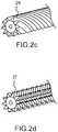
- Figures 2b and 2cshow a tip portion that includes protrusions with triangular cross-section that form a plurality of substantially linear ridges 23 on a catheter with circular cross-section.
- Figure 2cshows a tip portion that includes protrusions with triangular cross-section that form a plurality of curved ridges 25 on a catheter with circular cross-section.
- the protrusions of any size or shapemay be oriented to form one or more discontinuous ridges on a surface of the catheter of any cross-sectional shape.
- An example of a catheter according to this embodimentis shown in Figure 2d.
- Figure 2dshows a tip portion that includes protrusions with triangular cross-section that form a plurality of discontinuous ridges 27 on a catheter with circular cross-section.
- one or more protrusionsmay be of any size or shape and be oriented randomly on a surface of the tip portion of the catheter of any cross-sectional shape.
- An example of a catheter according to this embodimentis shown in Figures 3a and 3b.
- Figures 3a and 3bshows the tip portion 36 of a catheter with a plurality of protrusions 31 that are arranged randomly.
- one or more protrusionsmay be formed integrally with the catheter of any cross-sectional shape.
- the protrusionsmay be of any size or shape and may be arranged in any way including, but not limited to, randomly oriented or one or more continuous or discontinuous ridges that are substantially linear or curved.
- FIG. 4a and 4bAn example of a catheter according to this embodiment of the invention is shown in Figures 4a and 4b .
- two integrally formed protrusions 41 with triangular cross-sectionare arranged at opposing sides of the tip portion 46 of the catheter with circular cross-section to form continuous ridges.
- the catheter of the present inventionmay include any combination of the features described above.
- the catheter of the present inventionis described above as being useful for initiating mechanical pleurodesis to treat pleural diseases such as pleural effusions and pneumothorax, the catheter may also be used in any type of medical procedure that requires irritating or roughening a surface.
- the cathetersmay be used in conjunction with other medical instruments including, but not limited to, pleural shunts, ascetic shunts, hydro-cephalic shunts.
Landscapes
- Health & Medical Sciences (AREA)
- Life Sciences & Earth Sciences (AREA)
- Pulmonology (AREA)
- General Health & Medical Sciences (AREA)
- Veterinary Medicine (AREA)
- Engineering & Computer Science (AREA)
- Biomedical Technology (AREA)
- Heart & Thoracic Surgery (AREA)
- Public Health (AREA)
- Animal Behavior & Ethology (AREA)
- Anesthesiology (AREA)
- Hematology (AREA)
- Biophysics (AREA)
- Surgery (AREA)
- Emergency Medicine (AREA)
- Vascular Medicine (AREA)
- Nuclear Medicine, Radiotherapy & Molecular Imaging (AREA)
- Medical Informatics (AREA)
- Molecular Biology (AREA)
- Media Introduction/Drainage Providing Device (AREA)
Description
- The present invention relates to an improved catheter design for use in treating pleural diseases.
- The pleural cavity and the pleura serve an important function of aiding in the optimal functioning of the lungs during respiration. Diseases affecting the pleural cavity and pleura include pleural effusions and pneumothorax. Pleural effusions involve the build-up of fluid around the lungs. Pleural effusions can be associated with conditions such as cancer, tuberculosis, congestive heart failure, pneumonia, pulmonary emboli, viral disease, cirrhosis, post coronary artery bypass graft surgery, gastrointestinal disease, tuberculosis, and mesothelioma. Pneumothorax occurs when air or gas is present in the pleural cavity.
- Patients with pleural diseases such as symptomatic pleural effusions or pneumothorax are typically treated with thoracentesis to remove fluid or air, and/or chemical or mechanical pleurodesis. Pleurodesis involves irritation of the parietal and/or visceral layers of the pleura to close off the pleural cavity and prevent further fluid and/or air accumulations. Pleurodesis is typically characterized by the creation of fibrous adhesions between the parietal and visceral layers of the pleura.
- Mechanical pleurodesis can be achieved, for example, with the insertion of a rough pad or a catheter into the pleural cavity. Catheters are used in many medical procedures and are typically inserted into a patient's body cavity, duct, or vessel. Catheters are typically used to drain fluids, inject fluids, and to provide access for surgical instruments into or from a body cavity. Catheters may allow a user, such as a doctor, nurse, or other medical professional, to access a specific portion of a patient's body without making invasive incisions.
- When using a catheter to perform mechanical pleurodesis, the tip of the catheter may be used to irritate the parietal and/or visceral layers of the pleura, thereby causing the creation of fibrous adhesions between the parietal and visceral layers. Typical catheters, however, are not highly effective in adequately irritating the parietal and visceral layers because they are substantially smooth.
EP 0 384 476 A1 discloses a disposable catheter for urine diversion with a catheter shaft. The distal end of the catheter shaft is delimited by a funnel, and the proximal end is delimited by a tip, which tapers conically and ends in a spherical thickened area. The axis of the tip and the axis of the catheter shaft are arranged coaxially, and the tapered area of the tip merges into a short, neck-shaped section onto which the spherical thickened area is formed. The surface of the catheter shaft and of the tip can have microscopically small, half-rounded protuberances.US 2008/071341 A1 discloses a tip for an extraction device engageable with an elongated sheath member for extracting an implanted elongated structure, such as a cardiac lead, from an obstruction in a body vessel of a patient. The tip includes a tipbody having a proximal end, a distal end, and a passageway extendingtherethrough. The tip body proximal end is engageable with the distal end of the sheath member distal end. The passageway of the tip is aligned with the passagewayof the sheath such that the implanted structure is receivable therein. The tip body distal end includes a segment tapering toward a leading edge. A disrupter element, such as a plurality of helices, is disposed along the outer surface of the tip body distal end.US 2004/181251 A1 relates to a surgical abrading instrument for abrading knee tissue during e.g. an arthroscopic procedure, comprising an abrading head disposed distally and supported on solid a transition region extended distally from a distal opening of an inner tube.- Thus, there is a need in the art for an improved catheter design for use in treating pleural diseases.
- The present invention provides a catheter configured to be inserted within a patient's pleural space. The catheter may be inserted within the pleural cavity of a patient's lungs for initiating mechanical pleurodesis. The catheter includes a tip portion that is configured to irritate the pleura when the catheter is inserted in the pleural cavity. This irritation causes the creation of fibrous adhesions between the parietal and visceral layers that close off the pleural cavity and prevent further fluid and/or air accumulations that occur as a result of pleural diseases.
- The catheter of the invention has the features of independent claim 1.
- Preferred embodiments are disclosed in the dependent claims.
- Other novel features and advantages of the present invention will become apparent to those skilled in the art upon examination of the following or upon learning by practice of the invention.
Figure 1 shows a catheter according to an embodiment of the invention.Figure 2a is a cross-sectional view of a tip portion of a catheter according to an embodiment of the invention.Figure 2b is angled view of a tip portion of a catheter according to an embodiment of the invention.Figure 2c is angled view of a tip portion of a catheter according to another embodiment of the invention.Figure 2d is angled view of a tip portion of a catheter according to another embodiment of the invention.Figure 3a is a cross-sectional view of a tip portion of a catheter according to another embodiment of the invention.Figure 3b is angled view of a tip portion of a catheter according to another embodiment of the invention.Figure 4a is a cross-sectional view of a tip portion of a catheter according to another embodiment of the invention.Figure 4b is angled view of a tip portion of a catheter according to another embodiment of the invention.- The present invention provides a catheter for use in treating pleural diseases, such as pleural effusions and pneumothorax. The catheter may be inserted within the pleural cavity of a patient's lungs for initiating mechanical pleurodesis. The catheter includes a tip portion that is positioned toward its distal end that is configured to irritate the pleura when the catheter is inserted in the pleural cavity. This irritation causes the creation of fibrous adhesions between the parietal and visceral layers that close off the pleural cavity and prevent further fluid and/or air accumulations that occur as a result of pleural diseases.
- The surface of the tip portion has a substantially rough configuration that is capable of irritating the pleura when the catheter is inserted in the pleural cavity. The tip portion's surface includes one or more protrusions that contact the pleura when the catheter is in use, thereby irritating the layers.
- The roughness of the tip portion may be varied to achieve a desired degree of irritation of the pleura based on a patient's condition. The catheter tip portion has a roughness of about 1,27 to about 15,24 microns (about 50 to about 600 microinches), measured according to the ANSI B46.1-2002 Surface Texture Standard is desirable to initiate pleurodesis.
- The shape, size, and arrangement of the protrusions may be varied to achieve a catheter tip surface with the desired roughness. The protrusions may be of any shape, size, and arrangement that can effectively irritate the pleura to initiate pleurodesis. For example, the cross-section of a protrusion may be polygonal, such as triangular, rectangular, or other polygonal. Alternatively, the cross-section of a protrusion may be substantially curved, such as circular, semi-circular or elliptical. In addition, any combination of cross-sections of protrusions may be used in a single catheter.
- The size of the protrusions may be varied depending on the degree of irritation of the pleura desired. Typically, larger protrusions result in a higher degree of irritation in the pleura than do smaller protrusions. The protrusions range in size from about 1,27 to about 15,24 microns (about 50 to about 600 microinches) in height measured on the surface of the catheter portion that is inserted in the pleural space. The protrusions are generally positioned near the tip portion of the catheter from about 12,7mm to about 381 mm (about 1/2 to about 15 inches) from the distal (inserted) end of the catheter. They may also be located at a portion of the catheter other than the tip portion, but still along a surface of the inserted portion of the catheter.
- The protrusions formed near or at the tip portion of the catheter according to the present invention may be substantially uniform or irregular in size and shape. For example, the size and shape of the protrusions may be varied along the length of the tip portion of the catheter to better irritate the pleura. Larger protrusions may be present at the proximal end of the catheter, while smaller ridges may be present towards the distal end of the catheter, thereby forming a cone-shaped tip portion.
- The protrusions may be arranged near or at the tip portion of the catheter in any orientation that allows the catheter to effectively irritate the pleura. In particular, the protrusions may be oriented randomly or oriented to form one or more continuous or discontinuous patterns on the surface of the catheter. For example, the protrusions may form ridges that may be substantially linear or curved. When the protrusions form a discontinuous ridge, the protrusions may appear as teeth at the tip portion of the catheter. If the catheter is oval in cross-section, the protrusions may be located on the elongated portion of the oval, and not along the curved portion of the oval, or vice versa, or on both the elongated and curved portions of the oval.
- The protrusions may be oriented closely together, or there may be some space between the protrusions. Further, the density of protrusions on a tip portion's surface may be varied in a single catheter. For example, a higher density of protrusions may be present towards the distal end of the inserted portion of the catheter while a lower density of protrusions may be present towards the proximal end of the inserted portion.
- The protrusions near or at the tip portion of the catheter may be formed of any material that is known in the art that is able to irritate the pleura. The material preferably has sufficient rigidity so that the protrusions are able to irritate the pleural layers. These materials may include, but are not limited to, silicone, PVC, polypropylene, polyurethane, other thermoplastic elastomers, etc.
- The protrusions may be formed by any method known in the art including, but not limited to, molding, extrusion, coextrusion, overmolding, machining, etching, EDM, sputtering, vapor deposition, etc. They may also be formed by various material removal or deposition techniques. The protrusions may be formed separately from and then attached to the tip portion of the catheter, or they may be formed integrally with the tip portion of the catheter.
- The catheter of the invention may be used to initiate pleurodesis by inserting the distal end of the catheter into the pleural cavity and contacting the protrusions at or near the distal tip portion of the catheter with the pleura. This contact between the protrusions and the pleura irritates the pleura, thus initiating pleurodesis. The contact may be achieved by the natural movement of the catheter positioned in the pleural space, or by a more active method such as by an external movement, agitation, or force such as a wire that is inserted through the catheter, a magnet that acts on the catheter, etc.
- Any shape, size, or style of catheter that is known in the art may be used in the present invention. The catheter typically has a circular cross-section, but it may be of any other shape including, but not limited to, oval, elliptical, triangular, rectangular, or other polygonal. The catheter may be flexible or rigid and may be made of any material that is known in the art. For example, the catheter may be made of a polymer, such as silicone, that is inert and unreactive to body fluids and a range of medical fluids with which it may come into contact, or other materials that are known to have at least a mildly irritating effect on human tissues or cells.
- The catheter of the invention may optionally include fenestrations, which allow fluid from a patient's body cavity to pass through them, thereby removing the fluid from the cavity towards a center lumen. The size of the fenestrations may vary, but they are typically of a size sufficient to allow bodily fluids to pass through them without clogging. The fenestrations may be arranged randomly or in a specified pattern.
- The catheter may also include a cuff that assists in positioning the catheter in a patient's body cavity and in surrounding tissues and may reduce the occurrence of infection by creating a seal that prevents external microorganisms from penetrating and infecting the pleural space. The cuff may be made of any suitable material that is commonly used in catheters including, but not limited to, polyester.
- An example of a catheter according to an embodiment of the invention is shown in
Figure 1 . Thecatheter 10 includes adistal end 12 and aproximal end 14. Atip portion 16 is positioned towards or at thedistal end 12 and includesprotrusions 11. Theproximal end 14 may be joined to a drainage container or other medical device. Thecatheter 10 may include acuff 18. - According to an embodiment of the invention, a catheter of any cross-section includes a tip portion towards or at its distal end that has one or more protrusions of any size or shape. The protrusions may be positioned on a surface of the tip portion of the catheter.
- An example of a tip portion with protrusions according to this embodiment is shown in
Figure 2a . InFigure 2a , thetip portion 26 includes a plurality ofprotrusions 21, which have a triangular cross-section, that are positioned on the surface of the catheter, which has a circular cross-section. - According to an embodiment of the invention, protrusions of any size or shape are arranged in a pattern on a surface of the tip portion of the catheter of any cross-sectional shape. For example, the pattern may include one or more continuous ridges on the surface of the tip portion. The ridges may be substantially linear or curved. Examples of catheter tips according to these embodiments are shown in
Figures 2b and2c .Figure 2b shows a tip portion that includes protrusions with triangular cross-section that form a plurality of substantiallylinear ridges 23 on a catheter with circular cross-section.Figure 2c shows a tip portion that includes protrusions with triangular cross-section that form a plurality ofcurved ridges 25 on a catheter with circular cross-section. - According to another embodiment of the invention, the protrusions of any size or shape may be oriented to form one or more discontinuous ridges on a surface of the catheter of any cross-sectional shape. An example of a catheter according to this embodiment is shown in
Figure 2d. Figure 2d shows a tip portion that includes protrusions with triangular cross-section that form a plurality ofdiscontinuous ridges 27 on a catheter with circular cross-section. - According to another embodiment of the invention, one or more protrusions may be of any size or shape and be oriented randomly on a surface of the tip portion of the catheter of any cross-sectional shape. An example of a catheter according to this embodiment is shown in
Figures 3a and 3b. Figures 3a and 3b shows thetip portion 36 of a catheter with a plurality ofprotrusions 31 that are arranged randomly. - According to another embodiment of the invention, one or more protrusions may be formed integrally with the catheter of any cross-sectional shape. The protrusions may be of any size or shape and may be arranged in any way including, but not limited to, randomly oriented or one or more continuous or discontinuous ridges that are substantially linear or curved.
- An example of a catheter according to this embodiment of the invention is shown in
Figures 4a and 4b . InFigures 4a and 4b , two integrally formedprotrusions 41 with triangular cross-section are arranged at opposing sides of thetip portion 46 of the catheter with circular cross-section to form continuous ridges. - The catheter of the present invention may include any combination of the features described above.
- Although the catheter of the present invention is described above as being useful for initiating mechanical pleurodesis to treat pleural diseases such as pleural effusions and pneumothorax, the catheter may also be used in any type of medical procedure that requires irritating or roughening a surface. In addition, the catheters may be used in conjunction with other medical instruments including, but not limited to, pleural shunts, ascetic shunts, hydro-cephalic shunts.
Claims (16)
- A catheter (10) configured to be inserted within a patient's pleural space, comprising:a tip portion (16;26;36;46); anda plurality of protrusions (11;21;31;41) positioned along an external surface of the catheter at or near the tip portion,characterized in that the plurality of protrusions are configured such that the tip portion has a roughness of about 1,27 to about 15,24 microns measured according to the ANSI B46.1-2002 Surface Texture Standard, andin that the protrusions have a height of about 1,27 to about 15,24 microns measured on the surface of the catheter portion that is inserted in the pleural space.
- The catheter of claim 1, wherein the tip portion is located at an end (12) of the catheter.
- The catheter of claim 1, wherein the protrusions have a shape selected from the group consisting of circular, elliptical, triangular, rectangular, or other polygonal.
- The catheter of claim 1, wherein the protrusions (31) are oriented randomly along the external surface of the catheter at or near the tip portion of the catheter.
- The catheter of claim 1, wherein the protrusions form continuous ridges (23; 25) at the tip portion.
- The catheter of claim 1, wherein the protrusions form discontinuous ridges (27) at the tip portion.
- The catheter of claim 5, wherein the continuous ridges (23) are substantially linear.
- The catheter of claim 5, wherein the continuous ridges (25) are curved.
- The catheter of claim 6, wherein the discontinuous ridges (27) are curved.
- The catheter of claim 6, wherein the discontinuous ridges (27) are substantially linear.
- The catheter of claim 1, wherein the protrusions are formed integrally with the tip portion.
- The catheter of claim 1, where the protrusions are configured to contact the patient's pleura to perform mechanical pleurodesis when the catheter is moved within the patient's pleural space.
- The catheter of claim 1, comprising a cuff (18) arranged between proximal (14) and distal (12) ends of the body.
- The catheter of claim 1, wherein a cross-section of the catheter has a shape selected from a group consisting of circular, ovular, elliptical, triangular and rectangular.
- The catheter of claim 1, wherein the catheter is formed from an inert polymer that is rigid or flexible.
- The catheter of claim 1, comprising fenestrations configured to receive fluid.
Applications Claiming Priority (2)
| Application Number | Priority Date | Filing Date | Title |
|---|---|---|---|
| US33254710P | 2010-05-07 | 2010-05-07 | |
| PCT/US2011/035545WO2011140456A2 (en) | 2010-05-07 | 2011-05-06 | Improved catheter design for use in treating pleural diseases |
Publications (3)
| Publication Number | Publication Date |
|---|---|
| EP2566561A2 EP2566561A2 (en) | 2013-03-13 |
| EP2566561A4 EP2566561A4 (en) | 2017-08-16 |
| EP2566561B1true EP2566561B1 (en) | 2019-04-24 |
Family
ID=44904503
Family Applications (1)
| Application Number | Title | Priority Date | Filing Date |
|---|---|---|---|
| EP11778425.6ANot-in-forceEP2566561B1 (en) | 2010-05-07 | 2011-05-06 | Improved catheter design for use in treating pleural diseases |
Country Status (11)
| Country | Link |
|---|---|
| US (2) | US10799263B2 (en) |
| EP (1) | EP2566561B1 (en) |
| JP (1) | JP2013526299A (en) |
| KR (1) | KR20130108999A (en) |
| CN (1) | CN103079627B (en) |
| AU (1) | AU2011247918B2 (en) |
| BR (1) | BR112012028533A8 (en) |
| CA (1) | CA2797843A1 (en) |
| ES (1) | ES2738478T3 (en) |
| MX (1) | MX337198B (en) |
| WO (1) | WO2011140456A2 (en) |
Families Citing this family (5)
| Publication number | Priority date | Publication date | Assignee | Title |
|---|---|---|---|---|
| US9867931B2 (en) | 2013-10-02 | 2018-01-16 | Cook Medical Technologies Llc | Therapeutic agents for delivery using a catheter and pressure source |
| CN103736194A (en)* | 2013-12-27 | 2014-04-23 | 黄耀 | Rotary cannula structure |
| KR102059741B1 (en) | 2018-03-13 | 2020-02-11 | 부산대학교병원 | Precisely steerable catheter tube with stiffness having directionality and longitudinal variability |
| EP4161346A2 (en) | 2020-06-05 | 2023-04-12 | Cook Medical Technologies LLC | Medical scopes for delivering therapeutic agents |
| CN115990050A (en)* | 2021-10-19 | 2023-04-21 | 微创神通医疗科技(上海)有限公司 | catheter |
Citations (1)
| Publication number | Priority date | Publication date | Assignee | Title |
|---|---|---|---|---|
| US20040181251A1 (en)* | 2003-03-11 | 2004-09-16 | Hacker Randall L. | Surgical abrader with suction port proximal to bearing |
Family Cites Families (30)
| Publication number | Priority date | Publication date | Assignee | Title |
|---|---|---|---|---|
| US4830615A (en)* | 1987-07-02 | 1989-05-16 | Goldstein Ronald E | Two-grit cutting and polishing instruments |
| DE3905552A1 (en)* | 1989-02-23 | 1990-08-30 | Liebenzeller Verpackung | DISPOSABLE CATHETER FOR DISCHARGE |
| US5545132A (en)* | 1993-12-21 | 1996-08-13 | C. R. Bard, Inc. | Helically grooved balloon for dilatation catheter and method of using |
| CN2201117Y (en)* | 1994-07-12 | 1995-06-21 | 中国人民解放军第四五二医院 | Medical thoracic cavity drainage tube |
| US20070066972A1 (en)* | 2001-11-29 | 2007-03-22 | Medwaves, Inc. | Ablation catheter apparatus with one or more electrodes |
| US7149586B2 (en)* | 2002-03-28 | 2006-12-12 | Second Sight Medical Products, Inc. | Variable pitch electrode array |
| US20020183781A1 (en)* | 2001-04-17 | 2002-12-05 | Brendan Casey | Catheter |
| US20040073259A1 (en)* | 2002-08-28 | 2004-04-15 | Martin Munzer | Treatment of patients infected by disease causing organisms or biological warfare agents using hyperthermia |
| US6921396B1 (en) | 2002-08-30 | 2005-07-26 | Arrow International, Inc. | Multi-lumen catheter with integrated connector |
| US7862575B2 (en)* | 2003-05-21 | 2011-01-04 | Yale University | Vascular ablation apparatus and method |
| US7008438B2 (en)* | 2003-07-14 | 2006-03-07 | Scimed Life Systems, Inc. | Anchored PTCA balloon |
| US8221387B2 (en) | 2004-02-24 | 2012-07-17 | Boston Scientific Scimed, Inc. | Catheter having an improved distal tip |
| US20050245846A1 (en)* | 2004-05-03 | 2005-11-03 | Casey Don E | Vibrating, magnetically guidable catheter with magnetic powder commingled with resin, extruded as an integral part the catheter |
| CA2570261C (en)* | 2004-07-08 | 2014-06-10 | Pneumrx, Inc. | Pleural effusion treatment device, method and material |
| WO2006042157A1 (en)* | 2004-10-06 | 2006-04-20 | Cook Incorporated | A flexible tip |
| US8220460B2 (en) | 2004-11-19 | 2012-07-17 | Portaero, Inc. | Evacuation device and method for creating a localized pleurodesis |
| US7824366B2 (en)* | 2004-12-10 | 2010-11-02 | Portaero, Inc. | Collateral ventilation device with chest tube/evacuation features and method |
| US10653440B2 (en)* | 2005-04-15 | 2020-05-19 | Cook Medical Technologies Llc | Tip for lead extraction device |
| DE102005034010A1 (en)* | 2005-07-18 | 2007-01-25 | Coltène/Whaledent GmbH + Co. KG | Root canal instrument with abrasive coating and method of making the same |
| US20070078442A1 (en) | 2005-08-24 | 2007-04-05 | Mayse Martin L | Tapered attachment for pleural catheter |
| US20080221566A1 (en)* | 2005-11-29 | 2008-09-11 | Krishnan Subramaniam C | Method and apparatus for detecting and achieving closure of patent foramen ovale |
| US7406963B2 (en)* | 2006-01-17 | 2008-08-05 | Portaero, Inc. | Variable resistance pulmonary ventilation bypass valve and method |
| WO2007103161A2 (en)* | 2006-03-08 | 2007-09-13 | Wilson-Cook Medical Inc. | Rotary dilator with internal threading |
| US20080021415A1 (en)* | 2006-04-07 | 2008-01-24 | Anthony Durkin | Device suitable for connection to a substantially tubular element |
| US8979872B2 (en)* | 2007-03-13 | 2015-03-17 | Longevity Surgical, Inc. | Devices for engaging, approximating and fastening tissue |
| US8163034B2 (en)* | 2007-05-11 | 2012-04-24 | Portaero, Inc. | Methods and devices to create a chemically and/or mechanically localized pleurodesis |
| US7879056B2 (en) | 2007-10-11 | 2011-02-01 | Keith Butterfield | Pleurabrade device |
| AU2008326154B2 (en) | 2007-10-30 | 2013-12-12 | Uti Limited Partnership | Method and system for sustained-release of sclerosing agent |
| WO2009105432A2 (en)* | 2008-02-19 | 2009-08-27 | Portaero, Inc. | Devices and methods for delivery of a therapeutic agent through a pneumostoma |
| US8518053B2 (en)* | 2009-02-11 | 2013-08-27 | Portaero, Inc. | Surgical instruments for creating a pneumostoma and treating chronic obstructive pulmonary disease |
- 2011
- 2011-05-06AUAU2011247918Apatent/AU2011247918B2/ennot_activeCeased
- 2011-05-06MXMX2012012979Apatent/MX337198B/enactiveIP Right Grant
- 2011-05-06JPJP2013509296Apatent/JP2013526299A/ennot_activeWithdrawn
- 2011-05-06EPEP11778425.6Apatent/EP2566561B1/ennot_activeNot-in-force
- 2011-05-06CACA2797843Apatent/CA2797843A1/ennot_activeAbandoned
- 2011-05-06CNCN201180022936.9Apatent/CN103079627B/ennot_activeExpired - Fee Related
- 2011-05-06USUS13/696,555patent/US10799263B2/enactiveActive
- 2011-05-06WOPCT/US2011/035545patent/WO2011140456A2/enactiveApplication Filing
- 2011-05-06BRBR112012028533Apatent/BR112012028533A8/ennot_activeApplication Discontinuation
- 2011-05-06ESES11778425Tpatent/ES2738478T3/enactiveActive
- 2011-05-06KRKR1020127032184Apatent/KR20130108999A/ennot_activeAbandoned
- 2020
- 2020-10-12USUS17/068,593patent/US12004770B2/enactiveActive
Patent Citations (1)
| Publication number | Priority date | Publication date | Assignee | Title |
|---|---|---|---|---|
| US20040181251A1 (en)* | 2003-03-11 | 2004-09-16 | Hacker Randall L. | Surgical abrader with suction port proximal to bearing |
Also Published As
| Publication number | Publication date |
|---|---|
| WO2011140456A2 (en) | 2011-11-10 |
| EP2566561A4 (en) | 2017-08-16 |
| US12004770B2 (en) | 2024-06-11 |
| AU2011247918A1 (en) | 2012-12-20 |
| MX2012012979A (en) | 2013-04-03 |
| US20210022761A1 (en) | 2021-01-28 |
| US10799263B2 (en) | 2020-10-13 |
| EP2566561A2 (en) | 2013-03-13 |
| CA2797843A1 (en) | 2011-11-10 |
| BR112012028533A2 (en) | 2016-07-26 |
| RU2012153206A (en) | 2014-06-20 |
| US20130204279A1 (en) | 2013-08-08 |
| MX337198B (en) | 2016-02-16 |
| BR112012028533A8 (en) | 2017-06-06 |
| JP2013526299A (en) | 2013-06-24 |
| WO2011140456A3 (en) | 2012-04-05 |
| AU2011247918B2 (en) | 2015-03-26 |
| KR20130108999A (en) | 2013-10-07 |
| ES2738478T3 (en) | 2020-01-23 |
| CN103079627A (en) | 2013-05-01 |
| CN103079627B (en) | 2016-03-30 |
Similar Documents
| Publication | Publication Date | Title |
|---|---|---|
| US12004770B2 (en) | Catheter design for use in treating pleural diseases | |
| EP2633828B1 (en) | Introducer assembly | |
| US9381037B2 (en) | Catheter tunneling systems, instruments and methods | |
| JP5764577B2 (en) | Endoscope sheath | |
| JP5050051B2 (en) | Surgical opening plug for preventing body fluid overflow | |
| JP5717884B2 (en) | Catheter guide wire introduction device | |
| JP6855286B2 (en) | Medical devices and systems | |
| CN116920264A (en) | Medical tube cleaning | |
| EP1694245A1 (en) | Stent | |
| JP3233953B2 (en) | Catheter device | |
| EP2769744B1 (en) | Medical product and medical set for the drainage of pathological accumulation of fluids | |
| AU2002305100B2 (en) | Medical instrument with an atraumatic end | |
| AU2002305100A1 (en) | Medical instrument with an atraumatic end | |
| JP2024147749A (en) | Bendable trocar having a blunt tip and connector for advancing a wound drainage catheter through tissue - Patents.com | |
| CN210301984U (en) | Catheter with adjustable hardness and intervention device | |
| RU2574130C2 (en) | Improved construction of catheter for application in treatment of pleural diseases | |
| US20030040768A1 (en) | Stoma dilator | |
| JPH0670746U (en) | Medical drain tube | |
| EP4385552A1 (en) | An introducer assembly having a low-profile access sheath and a hub assembly | |
| JP2002272755A (en) | Trocar catheter | |
| JP2002315836A (en) | Guide wire introduction auxiliary tool and catheter provided with it | |
| WO2024248088A1 (en) | Puncture dilator | |
| CN113693680A (en) | Biliary stent | |
| CN114191156A (en) | A catheter for placing multiple stents | |
| WO2011106383A2 (en) | A catheter |
Legal Events
| Date | Code | Title | Description |
|---|---|---|---|
| PUAI | Public reference made under article 153(3) epc to a published international application that has entered the european phase | Free format text:ORIGINAL CODE: 0009012 | |
| 17P | Request for examination filed | Effective date:20121123 | |
| AK | Designated contracting states | Kind code of ref document:A2 Designated state(s):AL AT BE BG CH CY CZ DE DK EE ES FI FR GB GR HR HU IE IS IT LI LT LU LV MC MK MT NL NO PL PT RO RS SE SI SK SM TR | |
| DAX | Request for extension of the european patent (deleted) | ||
| A4 | Supplementary search report drawn up and despatched | Effective date:20170719 | |
| RIC1 | Information provided on ipc code assigned before grant | Ipc:A61M 16/04 20060101ALI20170713BHEP Ipc:A61M 25/00 20060101ALI20170713BHEP Ipc:A61M 31/00 20060101ALI20170713BHEP Ipc:A61M 25/01 20060101AFI20170713BHEP Ipc:A61B 17/3207 20060101ALI20170713BHEP Ipc:A61M 25/16 20060101ALI20170713BHEP | |
| STAA | Information on the status of an ep patent application or granted ep patent | Free format text:STATUS: EXAMINATION IS IN PROGRESS | |
| 17Q | First examination report despatched | Effective date:20180605 | |
| GRAP | Despatch of communication of intention to grant a patent | Free format text:ORIGINAL CODE: EPIDOSNIGR1 | |
| STAA | Information on the status of an ep patent application or granted ep patent | Free format text:STATUS: GRANT OF PATENT IS INTENDED | |
| INTG | Intention to grant announced | Effective date:20181114 | |
| GRAS | Grant fee paid | Free format text:ORIGINAL CODE: EPIDOSNIGR3 | |
| GRAA | (expected) grant | Free format text:ORIGINAL CODE: 0009210 | |
| STAA | Information on the status of an ep patent application or granted ep patent | Free format text:STATUS: THE PATENT HAS BEEN GRANTED | |
| AK | Designated contracting states | Kind code of ref document:B1 Designated state(s):AL AT BE BG CH CY CZ DE DK EE ES FI FR GB GR HR HU IE IS IT LI LT LU LV MC MK MT NL NO PL PT RO RS SE SI SK SM TR | |
| REG | Reference to a national code | Ref country code:GB Ref legal event code:FG4D | |
| REG | Reference to a national code | Ref country code:CH Ref legal event code:EP | |
| REG | Reference to a national code | Ref country code:DE Ref legal event code:R096 Ref document number:602011058335 Country of ref document:DE | |
| REG | Reference to a national code | Ref country code:AT Ref legal event code:REF Ref document number:1123398 Country of ref document:AT Kind code of ref document:T Effective date:20190515 Ref country code:IE Ref legal event code:FG4D | |
| REG | Reference to a national code | Ref country code:NL Ref legal event code:MP Effective date:20190424 | |
| REG | Reference to a national code | Ref country code:LT Ref legal event code:MG4D | |
| PG25 | Lapsed in a contracting state [announced via postgrant information from national office to epo] | Ref country code:NL Free format text:LAPSE BECAUSE OF FAILURE TO SUBMIT A TRANSLATION OF THE DESCRIPTION OR TO PAY THE FEE WITHIN THE PRESCRIBED TIME-LIMIT Effective date:20190424 | |
| PG25 | Lapsed in a contracting state [announced via postgrant information from national office to epo] | Ref country code:LT Free format text:LAPSE BECAUSE OF FAILURE TO SUBMIT A TRANSLATION OF THE DESCRIPTION OR TO PAY THE FEE WITHIN THE PRESCRIBED TIME-LIMIT Effective date:20190424 Ref country code:NO Free format text:LAPSE BECAUSE OF FAILURE TO SUBMIT A TRANSLATION OF THE DESCRIPTION OR TO PAY THE FEE WITHIN THE PRESCRIBED TIME-LIMIT Effective date:20190724 Ref country code:PT Free format text:LAPSE BECAUSE OF FAILURE TO SUBMIT A TRANSLATION OF THE DESCRIPTION OR TO PAY THE FEE WITHIN THE PRESCRIBED TIME-LIMIT Effective date:20190824 Ref country code:AL Free format text:LAPSE BECAUSE OF FAILURE TO SUBMIT A TRANSLATION OF THE DESCRIPTION OR TO PAY THE FEE WITHIN THE PRESCRIBED TIME-LIMIT Effective date:20190424 Ref country code:SE Free format text:LAPSE BECAUSE OF FAILURE TO SUBMIT A TRANSLATION OF THE DESCRIPTION OR TO PAY THE FEE WITHIN THE PRESCRIBED TIME-LIMIT Effective date:20190424 Ref country code:HR Free format text:LAPSE BECAUSE OF FAILURE TO SUBMIT A TRANSLATION OF THE DESCRIPTION OR TO PAY THE FEE WITHIN THE PRESCRIBED TIME-LIMIT Effective date:20190424 Ref country code:FI Free format text:LAPSE BECAUSE OF FAILURE TO SUBMIT A TRANSLATION OF THE DESCRIPTION OR TO PAY THE FEE WITHIN THE PRESCRIBED TIME-LIMIT Effective date:20190424 | |
| PGFP | Annual fee paid to national office [announced via postgrant information from national office to epo] | Ref country code:IT Payment date:20190731 Year of fee payment:9 Ref country code:DE Payment date:20190726 Year of fee payment:9 Ref country code:FR Payment date:20190730 Year of fee payment:9 Ref country code:ES Payment date:20190731 Year of fee payment:9 | |
| PG25 | Lapsed in a contracting state [announced via postgrant information from national office to epo] | Ref country code:GR Free format text:LAPSE BECAUSE OF FAILURE TO SUBMIT A TRANSLATION OF THE DESCRIPTION OR TO PAY THE FEE WITHIN THE PRESCRIBED TIME-LIMIT Effective date:20190725 Ref country code:LV Free format text:LAPSE BECAUSE OF FAILURE TO SUBMIT A TRANSLATION OF THE DESCRIPTION OR TO PAY THE FEE WITHIN THE PRESCRIBED TIME-LIMIT Effective date:20190424 Ref country code:PL Free format text:LAPSE BECAUSE OF FAILURE TO SUBMIT A TRANSLATION OF THE DESCRIPTION OR TO PAY THE FEE WITHIN THE PRESCRIBED TIME-LIMIT Effective date:20190424 Ref country code:RS Free format text:LAPSE BECAUSE OF FAILURE TO SUBMIT A TRANSLATION OF THE DESCRIPTION OR TO PAY THE FEE WITHIN THE PRESCRIBED TIME-LIMIT Effective date:20190424 Ref country code:BG Free format text:LAPSE BECAUSE OF FAILURE TO SUBMIT A TRANSLATION OF THE DESCRIPTION OR TO PAY THE FEE WITHIN THE PRESCRIBED TIME-LIMIT Effective date:20190724 | |
| REG | Reference to a national code | Ref country code:AT Ref legal event code:MK05 Ref document number:1123398 Country of ref document:AT Kind code of ref document:T Effective date:20190424 | |
| REG | Reference to a national code | Ref country code:CH Ref legal event code:PL | |
| PG25 | Lapsed in a contracting state [announced via postgrant information from national office to epo] | Ref country code:IS Free format text:LAPSE BECAUSE OF FAILURE TO SUBMIT A TRANSLATION OF THE DESCRIPTION OR TO PAY THE FEE WITHIN THE PRESCRIBED TIME-LIMIT Effective date:20190824 | |
| PGFP | Annual fee paid to national office [announced via postgrant information from national office to epo] | Ref country code:GB Payment date:20190730 Year of fee payment:9 | |
| REG | Reference to a national code | Ref country code:ES Ref legal event code:FG2A Ref document number:2738478 Country of ref document:ES Kind code of ref document:T3 Effective date:20200123 | |
| REG | Reference to a national code | Ref country code:DE Ref legal event code:R097 Ref document number:602011058335 Country of ref document:DE | |
| PG25 | Lapsed in a contracting state [announced via postgrant information from national office to epo] | Ref country code:LI Free format text:LAPSE BECAUSE OF NON-PAYMENT OF DUE FEES Effective date:20190531 Ref country code:CZ Free format text:LAPSE BECAUSE OF FAILURE TO SUBMIT A TRANSLATION OF THE DESCRIPTION OR TO PAY THE FEE WITHIN THE PRESCRIBED TIME-LIMIT Effective date:20190424 Ref country code:AT Free format text:LAPSE BECAUSE OF FAILURE TO SUBMIT A TRANSLATION OF THE DESCRIPTION OR TO PAY THE FEE WITHIN THE PRESCRIBED TIME-LIMIT Effective date:20190424 Ref country code:MC Free format text:LAPSE BECAUSE OF FAILURE TO SUBMIT A TRANSLATION OF THE DESCRIPTION OR TO PAY THE FEE WITHIN THE PRESCRIBED TIME-LIMIT Effective date:20190424 Ref country code:DK Free format text:LAPSE BECAUSE OF FAILURE TO SUBMIT A TRANSLATION OF THE DESCRIPTION OR TO PAY THE FEE WITHIN THE PRESCRIBED TIME-LIMIT Effective date:20190424 Ref country code:EE Free format text:LAPSE BECAUSE OF FAILURE TO SUBMIT A TRANSLATION OF THE DESCRIPTION OR TO PAY THE FEE WITHIN THE PRESCRIBED TIME-LIMIT Effective date:20190424 Ref country code:RO Free format text:LAPSE BECAUSE OF FAILURE TO SUBMIT A TRANSLATION OF THE DESCRIPTION OR TO PAY THE FEE WITHIN THE PRESCRIBED TIME-LIMIT Effective date:20190424 Ref country code:SK Free format text:LAPSE BECAUSE OF FAILURE TO SUBMIT A TRANSLATION OF THE DESCRIPTION OR TO PAY THE FEE WITHIN THE PRESCRIBED TIME-LIMIT Effective date:20190424 Ref country code:CH Free format text:LAPSE BECAUSE OF NON-PAYMENT OF DUE FEES Effective date:20190531 | |
| REG | Reference to a national code | Ref country code:BE Ref legal event code:MM Effective date:20190531 | |
| PG25 | Lapsed in a contracting state [announced via postgrant information from national office to epo] | Ref country code:SM Free format text:LAPSE BECAUSE OF FAILURE TO SUBMIT A TRANSLATION OF THE DESCRIPTION OR TO PAY THE FEE WITHIN THE PRESCRIBED TIME-LIMIT Effective date:20190424 Ref country code:LU Free format text:LAPSE BECAUSE OF NON-PAYMENT OF DUE FEES Effective date:20190506 | |
| PLBE | No opposition filed within time limit | Free format text:ORIGINAL CODE: 0009261 | |
| STAA | Information on the status of an ep patent application or granted ep patent | Free format text:STATUS: NO OPPOSITION FILED WITHIN TIME LIMIT | |
| PG25 | Lapsed in a contracting state [announced via postgrant information from national office to epo] | Ref country code:TR Free format text:LAPSE BECAUSE OF FAILURE TO SUBMIT A TRANSLATION OF THE DESCRIPTION OR TO PAY THE FEE WITHIN THE PRESCRIBED TIME-LIMIT Effective date:20190424 | |
| 26N | No opposition filed | Effective date:20200127 | |
| PG25 | Lapsed in a contracting state [announced via postgrant information from national office to epo] | Ref country code:IE Free format text:LAPSE BECAUSE OF NON-PAYMENT OF DUE FEES Effective date:20190506 | |
| PG25 | Lapsed in a contracting state [announced via postgrant information from national office to epo] | Ref country code:BE Free format text:LAPSE BECAUSE OF NON-PAYMENT OF DUE FEES Effective date:20190531 Ref country code:SI Free format text:LAPSE BECAUSE OF FAILURE TO SUBMIT A TRANSLATION OF THE DESCRIPTION OR TO PAY THE FEE WITHIN THE PRESCRIBED TIME-LIMIT Effective date:20190424 | |
| REG | Reference to a national code | Ref country code:DE Ref legal event code:R119 Ref document number:602011058335 Country of ref document:DE | |
| GBPC | Gb: european patent ceased through non-payment of renewal fee | Effective date:20200506 | |
| PG25 | Lapsed in a contracting state [announced via postgrant information from national office to epo] | Ref country code:FR Free format text:LAPSE BECAUSE OF NON-PAYMENT OF DUE FEES Effective date:20200531 Ref country code:GB Free format text:LAPSE BECAUSE OF NON-PAYMENT OF DUE FEES Effective date:20200506 | |
| PG25 | Lapsed in a contracting state [announced via postgrant information from national office to epo] | Ref country code:DE Free format text:LAPSE BECAUSE OF NON-PAYMENT OF DUE FEES Effective date:20201201 Ref country code:CY Free format text:LAPSE BECAUSE OF FAILURE TO SUBMIT A TRANSLATION OF THE DESCRIPTION OR TO PAY THE FEE WITHIN THE PRESCRIBED TIME-LIMIT Effective date:20190424 | |
| PG25 | Lapsed in a contracting state [announced via postgrant information from national office to epo] | Ref country code:HU Free format text:LAPSE BECAUSE OF FAILURE TO SUBMIT A TRANSLATION OF THE DESCRIPTION OR TO PAY THE FEE WITHIN THE PRESCRIBED TIME-LIMIT; INVALID AB INITIO Effective date:20110506 Ref country code:MT Free format text:LAPSE BECAUSE OF FAILURE TO SUBMIT A TRANSLATION OF THE DESCRIPTION OR TO PAY THE FEE WITHIN THE PRESCRIBED TIME-LIMIT Effective date:20190424 | |
| REG | Reference to a national code | Ref country code:ES Ref legal event code:FD2A Effective date:20210928 | |
| PG25 | Lapsed in a contracting state [announced via postgrant information from national office to epo] | Ref country code:IT Free format text:LAPSE BECAUSE OF NON-PAYMENT OF DUE FEES Effective date:20200506 | |
| PG25 | Lapsed in a contracting state [announced via postgrant information from national office to epo] | Ref country code:ES Free format text:LAPSE BECAUSE OF NON-PAYMENT OF DUE FEES Effective date:20200507 | |
| PG25 | Lapsed in a contracting state [announced via postgrant information from national office to epo] | Ref country code:MK Free format text:LAPSE BECAUSE OF FAILURE TO SUBMIT A TRANSLATION OF THE DESCRIPTION OR TO PAY THE FEE WITHIN THE PRESCRIBED TIME-LIMIT Effective date:20190424 |