EP2564892A1 - Lead body with inner and outer co-axial coils - Google Patents
Lead body with inner and outer co-axial coilsDownload PDFInfo
- Publication number
- EP2564892A1 EP2564892A1EP12171266AEP12171266AEP2564892A1EP 2564892 A1EP2564892 A1EP 2564892A1EP 12171266 AEP12171266 AEP 12171266AEP 12171266 AEP12171266 AEP 12171266AEP 2564892 A1EP2564892 A1EP 2564892A1
- Authority
- EP
- European Patent Office
- Prior art keywords
- electrical conductors
- insulator
- insulated wires
- covered
- lead body
- Prior art date
- Legal status (The legal status is an assumption and is not a legal conclusion. Google has not performed a legal analysis and makes no representation as to the accuracy of the status listed.)
- Granted
Links
Images


Classifications
- A—HUMAN NECESSITIES
- A61—MEDICAL OR VETERINARY SCIENCE; HYGIENE
- A61N—ELECTROTHERAPY; MAGNETOTHERAPY; RADIATION THERAPY; ULTRASOUND THERAPY
- A61N1/00—Electrotherapy; Circuits therefor
- A61N1/02—Details
- A61N1/04—Electrodes
- A61N1/05—Electrodes for implantation or insertion into the body, e.g. heart electrode
- A61N1/0551—Spinal or peripheral nerve electrodes
- A—HUMAN NECESSITIES
- A61—MEDICAL OR VETERINARY SCIENCE; HYGIENE
- A61N—ELECTROTHERAPY; MAGNETOTHERAPY; RADIATION THERAPY; ULTRASOUND THERAPY
- A61N1/00—Electrotherapy; Circuits therefor
- A61N1/02—Details
- A61N1/04—Electrodes
- A61N1/05—Electrodes for implantation or insertion into the body, e.g. heart electrode
- H—ELECTRICITY
- H01—ELECTRIC ELEMENTS
- H01B—CABLES; CONDUCTORS; INSULATORS; SELECTION OF MATERIALS FOR THEIR CONDUCTIVE, INSULATING OR DIELECTRIC PROPERTIES
- H01B7/00—Insulated conductors or cables characterised by their form
- H01B7/04—Flexible cables, conductors, or cords, e.g. trailing cables
- H01B7/048—Flexible cables, conductors, or cords, e.g. trailing cables for implantation into a human or animal body, e.g. pacemaker leads
- Y—GENERAL TAGGING OF NEW TECHNOLOGICAL DEVELOPMENTS; GENERAL TAGGING OF CROSS-SECTIONAL TECHNOLOGIES SPANNING OVER SEVERAL SECTIONS OF THE IPC; TECHNICAL SUBJECTS COVERED BY FORMER USPC CROSS-REFERENCE ART COLLECTIONS [XRACs] AND DIGESTS
- Y10—TECHNICAL SUBJECTS COVERED BY FORMER USPC
- Y10T—TECHNICAL SUBJECTS COVERED BY FORMER US CLASSIFICATION
- Y10T29/00—Metal working
- Y10T29/49—Method of mechanical manufacture
- Y10T29/49002—Electrical device making
- Y10T29/49117—Conductor or circuit manufacturing
- Y10T29/49169—Assembling electrical component directly to terminal or elongated conductor
Definitions
- the present disclosurerelates to a lead body with inner and outer co-axial coils each having a plurality of discrete electrical paths.
- the inner and outer coilsare in direct physical contact and coiled in opposite directions.
- the human bodyimposes stringent requirements on electrical conductors that are implanted in it. Leads inserted in a living body that form a part of a stimulation and/or measuring device are subjected to almost continuous flexure during body movement. Also, a living body constitutes a site that is chemically and biologically hostile to anything that invades it. Consequently, leads ideally have good deformability, particularly bending ability, high fatigue resistance, corrosion resistance, and a high degree of electric conductance.
- U.S. Pat. No. 4,640,983discloses a lead body having at least one spiral which is formed from at least one conductor. Each conductor consists of wires that are stranded together to form a bundle. The wires belonging to a conductor can all consist of the same material or of different materials, one of which has a large breaking strength and the other one having high electric conductivity.
- One embodimentdiscloses inner and outer coils wound in the same direction and separated by an insulating sheath.
- U.S. Pat. No. 5,483,022discloses a lead body having at least one helical coil formed from at least one electrical cable. Each cable is formed from several wires twisted in a ropelike configuration. Each wire is a composite of a core of a highly conductive material and a coveting of a strong and biocompatible material, with all adjacent wires belonging to the same cable in un-insulated contact with each other.
- One embodimentdiscloses inner and outer coils wound in the same direction and separated by an insulating sheath.
- U.S. Pat. No. 6,978,185discloses a lead body having electrically active and inactive elements helically wound together. The active elements are separated from each other by the inactive elements.
- One embodimentdiscloses inner and outer coils wound in opposite directions and separated by an insulating sheath.
- the present disclosurerelates to a lead body with inner and outer co-axial coils each having a plurality of discrete electrical paths.
- the inner and outer coilsare coiled in opposite directions and in direct physical contact with each other.
- Embodiments with twelve discrete electrical pathsare disclosed.
- the conductor deviceprovides a relatively high electric conductance with great flexibility, expandability, breaking strength and, in particular, fatigue resistance.
- One embodimentis directed to a biomedical conductor assembly adapted for at least partial insertion in a living body.
- the conductor assemblyincludes a plurality of first and second electrical conductors each covered with an insulator.
- a plurality of the first electrical conductorsare helically wound in a first direction to form an inner coil with a lumen and a plurality of the second electrical connectors helically wound in a second opposite direction forming an outer coil in direct physical contact with the inner coil.
- An insulatorcovers the inner and outer coils.
- the plurality of second electrical conductorseach include a plurality of un-insulated wires twisted in a ropelike configuration around a central axis to form a plurality of cables. Each cable is covered with an insulator.
- the un-insulated wiresare preferably movable with respect to each within the insulator.
- the inner coilpreferably slides relative to the outer coil within the conductor assembly.
- the first electrical conductorseach optionally include a plurality of discrete insulated wires.
- the first electrical conductorsoptionally include a plurality of un-insulated wires twisted in a ropelike configuration around a central axis to form a cable wherein each cable is covered with an insulator.
- the un-insulated wires in the second electrical conductorsinclude a core of a first material surrounded by a covering of a second material.
- the second electrical conductorsinclude a center wire and a plurality of un-insulated wires twisted in a ropelike configuration around the center wire. The center wire preferably has a greater breaking strength than the un-insulated wires.
- the conductor assemblycan include any number of discrete conductors.
- the inner coilincludes four discrete insulated wires and the outer coil includes four or eight discrete insulated cables.
- the conductor assemblyincludes a plurality of the first electrical conductors each covered with an insulator and helically wound in a first direction to form an inner coil with a lumen.
- the second electrical conductorseach including a plurality of un-insulated wires twisted in a ropelike configuration around a central axis to form a plurality of cables covered with an insulator.
- the inner and outer coilsare covered by an insulator.
- the present disclosureis also directed to a therapy delivery element including an elongated lead body having a proximal end and a distal end.
- the lead bodyincludes a plurality of the first electrical conductors each covered with an insulator and helically wound in a first direction to form an inner coil with a lumen and a plurality of second electrical conductors each including a plurality of un-insulated wires twisted in a ropelike configuration around a central axis to form a plurality of cables.
- Each cableis covered with an insulator and helically wound in a second opposite direction forming an outer coil in direct physical contact with the inner coil.
- An insulatorcovers the inner and outer coils.
- At least one electrically conductive connectoris operatively associated with the proximal end of the lead body and at least one electrode is operatively associated with the distal end of the lead body.
- Each matched set of connectors and electrodesare electrically coupled with one of the first or second electrical conductors.
- the therapy delivery elementpreferably includes a stylet wire having a distal end inserted into the lumen through an opening at the proximal end of the lead body and a proximal end attached to a stylet handle.
- the present disclosureis also directed to a neurostimulation system including an implantable pulse generator and a therapy delivery element in accordance with an embodiment of the present disclosure.
- a stylet wire having a distal endis inserted into the lumen through an opening at the proximal end of the lead body and a proximal end attached to a stylet handle.
- the present disclosureis also directed to a method of making a therapy delivery element adapted for at least partial insertion in a living body.
- the methodincludes helically winding a plurality of the first electrical conductors each covered with an insulator in a first direction to form an inner coil with a lumen.
- a plurality of second electrical conductorsis helically wound in a second opposite direction forming an outer coil in direct physical contact with the inner coil.
- Each of the second electrical conductorsincludes a plurality of un-insulated wires twisted in a ropelike configuration around a central axis to form a plurality of cables covered with an insulator.
- An insulating coveringis applied to the inner and outer coils to form a lead body.
- At least one electrically conductive connectoris attached to a proximal end of the lead body and at least one electrode is attached to a distal end of the lead body.
- Each matched set of connectors and electrodesare electrically coupled with one of the first or second electrical conductors.
- the present disclosureis also directed to a method of implanting a neurostimulation system.
- the methodincludes grasping a stylet handle attached to a stylet wire inserted into a lumen of a therapy delivery element in accordance with an embodiment of the present disclosure.
- the electrodes at a distal end of a therapy delivery elementare steered to a target location within the living body.
- the styletis removed from the therapy delivery element.
- An implantable pulse generatoris implanted within the living body.
- the electrical contacts at the proximal end of the therapy delivery elementare electrically coupled with the implantable pulse generator.
- the present inventionmay also be directed to the subject-matter according to one or more of the following sections. Further, the features of these sections but also all features of the entire specification may be combined with one another.
- the description that followsrelates to spinal cord stimulation (SCS) system.
- SCSspinal cord stimulation
- the present disclosurelends itself well to applications in SCS, the disclosure in its broadest aspects may not be so limited. Rather, the disclosure may be used with any type of implantable therapy delivery system with one or more therapy delivery elements.
- the present disclosuremay be used as part of a pacemaker, a defibrillator, a cochlear stimulator, a retinal stimulator, a stimulator configured to produce coordinated limb movement, a cortical stimulator, a deep brain stimulator, peripheral nerve stimulator, microstimulator, or in any other neural stimulator configured to treat urinary incontinence, sleep apnea, shoulder sublaxation, headache, etc.
- one or more of the therapy delivery elementsmay be a fluid delivery conduit, such as a catheter, including an inner lumen that is placed to deliver a fluid, such as pharmaceutical agents, insulin, pain relieving agents, gene therapy agents, or the like from a fluid delivery device (e.g., a fluid reservoir and/or pump) to a respective target tissue site in a patient.
- a fluid delivery devicee.g., a fluid reservoir and/or pump
- one or more of the therapy delivery elementsmay be an electrical lead including one or more sensing electrodes to sense physiological parameters (e.g., blood pressure, temperature, cardiac activity, etc.) at a target tissue site within a patient.
- therapymay include stimulation therapy, sensing or monitoring of one or more physiological parameters, fluid delivery, and the like.
- Therapy delivery elementincludes pacing or defibrillation leads, stimulation leads, sensing leads, fluid delivery conduit, and any combination thereof.
- Target tissue siterefers generally to the target site for implantation of a therapy delivery element, regardless of the type of therapy.
- FIG. 1illustrates a generalized therapy delivery system 10 that may be used in spinal cord stimulation (SCS), as well as other stimulation applications.
- the therapy delivery system 10generally includes an implantable pulse generator 12 ("IPG") ("IPG"), an implantable therapy delivery element 14, which carries an array of electrodes 18 (shown exaggerated for purposes of illustration), and an optional implantable extension lead 16. Although only one therapy delivery element 14 is shown, typically two or more therapy delivery elements 14 are used with the therapy delivery system 10.
- the therapy delivery element 14includes lead body 40 having a proximal end 36 and a distal end 44.
- the lead body 40typically has a diameter of between about 0.03 inches to 0.07 inches and a length within the range of 30 cm to 90 cm for spinal cord stimulation applications.
- the lead body 40may include a suitable electrically insulative costing, such as, a polymer (e.g., polyurethane or silicone).
- proximal end 36 of the therapy delivery element 14is electrically coupled to distal end 38 of the extension lead 16 via a connector 20, typically associated with the extension lead 16.
- Proximal end 42 of the extension lead 16is electrically coupled to the implantable pulse generator 12 via connector 22 associated with housing 28.
- the proximal end 36 of the therapy delivery element 14can be electrically coupled directly to the connector 22.
- the implantable pulse generator 12includes electronic subassembly 24 (shown schematically), which includes control and pulse generation circuitry (not shown) for delivering electrical stimulation energy to the electrodes 18 of the therapy delivery element 14 in a controlled manner, and a power supply, such as battery 26.
- the implantable pulse generator 12provides a programmable stimulation signal (e.g., in the form of electrical pulses or substantially continuous-time signals) that is delivered to target stimulation sites by electrodes 18.
- a programmable stimulation signale.g., in the form of electrical pulses or substantially continuous-time signals
- the implantable pulse generator 12may provide the same or a different signal to the electrodes 18.
- the implantable pulse generator 12can take the form of an implantable receiver-stimulator in which the power source for powering the implanted receiver, as well as control circuitry to command the receiver-stimulator, are contained in an external controller inductively coupled to the receiver-stimulator via an electromagnetic link.
- the implantable pulse generator 12can take the form of an external trial stimulator (ETS), which has similar pulse generation circuitry as an IPG, but differs in that it is a non-implantable device that is used on a trial basis after the therapy delivery element 14 has been implanted and prior to implantation of the IPG, to test the responsiveness of the stimulation that is to be provided.
- ETSexternal trial stimulator
- the housing 28is composed of a biocompatible material, such as for example titanium, and forms a hermetically sealed compartment containing the electronic subassembly 24 and battery 26 protected from the body tissue and fluids.
- the connector 22is disposed in a portion of the housing 28 that is, at least initially, not sealed.
- the connector 22carries a plurality of contacts that electrically couple with respective terminals at proximal ends of the therapy delivery element 14 or extension lead 16. Electrical conductors extend from the connector 22 and connect to the electronic subassembly 24.
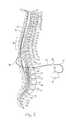
- Figure 2illustrates the therapy delivery element 14 implanted in the epidural space 30 of a patient in close proximity to the dura, the outer layer that surrounds the spinal cord 32, to deliver the intended therapeutic effects of spinal cord electrical stimulation.
- the target stimulation sitesmay be anywhere along the spinal cord 32, such as for example proximate the sacral nerves.
- the implantable pulse generator 12is generally implanted in a surgically-made pocket either in the abdomen or above the buttocks, such as illustrated in Figure 3 .
- the implantable pulse generator 12may, of course, also be implanted in other locations of the patient's body.
- Use of the extension lead 16facilitates locating the implantable pulse generator 12 away from the lead exit point 34.
- the extension lead 16serves as a lead adapter if the proximal end 36 of the therapy delivery element 14 is not compatible with the connector 22 of the implantable pulse generator 12, since different manufacturers use different connectors at the ends of their stimulation leads and are not always compatible with the connector 22.
- the therapy delivery system 10also may include a clinician programmer 46 and a patient programmer 48.
- Clinician programmer 46may be a handheld computing device that permits a clinician to program neurostimulation therapy for patient using input keys and a display.
- the clinicianmay specify neurostimulation parameters for use in delivery of neurostimulation therapy.
- Clinician programmer 46supports telemetry (e.g., radio frequency telemetry) with the implantable pulse generator 12 to download neurostimulation parameters and, optionally, upload operational or physiological data stored by implantable pulse generator 12. In this manner, the clinician may periodically interrogate the implantable pulse generator 12 to evaluate efficacy and, if necessary, modify the stimulation parameters.
- telemetrye.g., radio frequency telemetry
- patient programmer 48may be a handheld computing device. Patient programmer 48 may also include a display and input keys to allow patient to interact with patient programmer 48 and the implantable pulse generator 12. The patient programmer 48 provides patient with an interface for control of neurostimulation therapy provided by the implantable pulse generator 12. For example, patient may use patient programmer 48 to start, stop or adjust neurostimulation therapy. In particular, patient programmer 48 may permit patient to adjust stimulation parameters such as duration, amplitude, pulse width and pulse rate, within an adjustment range specified by the clinician via clinician programmer 46, or select from a library of stored stimulation therapy programs.
- stimulation parameterssuch as duration, amplitude, pulse width and pulse rate
- the implantable pulse generator 12, clinician programmer 46, and patient programmer 48may communicate via cables or a wireless communication.
- Clinician programmer 46 and patient programmer 48may, for example, communicate via wireless communication with the implantable pulse generator 12 using RF telemetry techniques known in the art.
- Clinician programmer 46 and patient programmer 48also may communicate with each other using any of a variety of local wireless communication techniques, such as RF communication according to the 802.11 or Bluetooth specification sets, infrared communication, e.g., according to the IrDA standard, or other standard or proprietary telemetry protocols.
- FIG. 3also illustrates a general environmental that may benefit from use of a tunneling tool in accordance with an embodiment of the present disclosure.
- the therapy delivery element 14 and/or the extension lead 16is typically routed through a pathway 52 subcutaneously formed along the torso of the patient to a subcutaneous pocket 54 where the implantable pulse generator 12 is located.
- pathway 52subcutaneously formed along the torso of the patient to a subcutaneous pocket 54 where the implantable pulse generator 12 is located.
- “lead” and “lead extension”are used interchangeably, unless content clearly dictates otherwise.
- the therapy delivery elements 14are typically fixed in place near the location selected by the clinician using the present suture anchors 60.
- the suture anchors 60can be positioned on the therapy delivery element 14 in a wide variety of locations and orientations to accommodate individual anatomical differences and the preferences of the clinician.
- the suture anchors 60may then be affixed to tissue using fasteners, such as for example, one or more sutures, staples, screws, or other fixation devices.
- the tissue to which the suture anchors 60 are affixedmay include subcutaneous fascia layer, bone, or some other type of tissue. Securing the suture anchors 60 to tissue in this manner prevents or reduces the chance that the therapy delivery element 14 will become dislodged or will migrate in an undesired manner.
- Figure 4Aillustrates the therapy delivery element 14 including one or more electrical contacts 15 at the proximal end 36, and one or more electrodes 18 at the distal end 44.
- the contacts 15 and electrodes 18are electrically coupled via insulated wires running through the therapy delivery element 14.
- Proximal end 36 of the therapy delivery element 14is electrically and mechanically coupled to implantable pulse generator 12 by the connector assembly 22.
- the connector assembly 22includes a plurality of discrete contacts 23 located in the housing 28 that electrically couple contact rings 15 on the proximal end of the therapy delivery element 14.
- the discrete contacts 23are electrically coupled to circuitry 24 in the implantable pulse generator 12 by conductive members 21.
- Each contact ring 15is electrically coupled to one or more of the electrodes 18 located at the distal end 44 of the therapy delivery element 14. Consequently, the implantable pulse generator 12 can independently deliver electrical impulses to each of the electrodes 18.
- the therapy delivery element 14can be coupled to the implantable pulse generator 12 through one or more lead extensions 16, as illustrated in Figure 4B .
- the connector 20 at the distal end 38 of the lead extension 16preferably includes a plurality of the contacts 23 configured in a manner similar to the connector assembly 22.
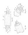
- FIGS 5A and 5Billustrate a stylet/lead assembly 70 including the therapy delivery element 14 in accordance with an embodiment of the present disclosure.
- styletrefers to a tool inserted into the lumen of a therapy delivery element, such as a neurostimulation lead, to stiffen the lead body and to facilitate its insertion into a target tissue.
- stylet 72includes stylet wire 74 attached to handle 76.
- the stylet wire 74has a diameter smaller than lumen 78 in the lead body 86 of the therapy delivery element 14.
- Length 80is typically the same, or slightly greater than, length 82 of the lumen 78 so the distal end 84 of the stylet wire 74 preferably reaches distal end 85 of the therapy delivery element 14.
- the distal end 85 of the therapy delivery elementis typically sealed, so the length 82 of the lumen 78 is less than the length of the therapy delivery element 14.
- distal end 84 of the stylet wire 74is inserted in lumen 78 of the therapy delivery element 14 to create the stylet/lead assembly 70.
- stylet wires for the SCS applicationare typically made of stainless steel or tungsten.
- Super-elastic materialsprovide excellent kink resistance but have poor resistance to buckling forces and torque. Consequently, a stylet wire 74 made from these materials alone is not be suitable for use for SCS therapy delivery elements.
- Stylet wires manufactured from combinations of linear and super-elastic materialshave been evaluated, as disclosed in U.S. Pat. Nos. 6,214,016 ; 6,168,571 ; 5,238,004 ; 6,270,496 and 5,957,966 , which are hereby incorporated by reference.
- FIGS. 6A and 6Bare cut-away views of a conductor assembly 100 for the lead body 86 having an inner coil 102 and outer coil 104 in accordance with an embodiment of the present disclosure.
- the inner coil 102includes a plurality of discrete electrical conductors 106 each covered with an insulator 108 and helically wound in a first direction 110 around lumen 78 that receives stylet wire 74.
- the outer coil 104includes a plurality of discrete electrical conductors 112 each covered with an insulator 114 and helically wound in a second opposite direction 116.
- the insulators 108, 114provide electrical integrity between each electrical conductor 106, 112 in the conductor assembly 100.
- the pitch of the inner and outer coils 102, 104can be the same or different.
- Insulator 118surrounds both the inner and outer coils 102, 104.
- the insulator 118is preferably a rubber-elastic, bendable and biologically compatible material, such as for example, an elastomer on a polyurethane or silicon base.
- the conductor assembly 100preferably includes at least one electrical conductor 106, 112 for each electrode 18.
- the inner and outer coils 102, 104each include four electrical conductors 106, 112, to support an eight-electrode lead.
- the inner coil 102includes four electrical conductors 106 and the outer coil 104 includes eight electrical conductors 112, to support a twelve-electrode lead. Any number of electrical conductors 106, 112 can be used in the present conductor assembly 100 to provide the desired number of circuit paths for the electrodes.
- the inner coil 102is preferably in direct physical contact with the outer coil 104, reducing the size of the conductor assembly 100 and increasing the density of available circuit paths. Winding the electrical conductors 106, 112 in opposite directions 110, 116 permits movement of the inner coil 102 relative to the outer coil 104 and permits the conductor assembly 100 to be bent with such a small radius of curvature without permanent or lasting deformation.
- the inner and outer coils 102, 104also permit the conductor assembly 100 to elastically expandable in longitudinal direction 130. Configuring the coils 102, 104 as opposing helical coils also enhances torque transfer by the lead body 86. The increased torque transfer aids during implantation of the therapy delivery element 14.
- the electrical conductors 106, 112can include a single conductive element, a plurality of conductive wires, or a combination thereof. As illustrated in Figure 6C , one or more of the electrical conductors 106, 112 optionally include a plurality of un-insulated conductive wires 120a-120g (collectively "120") twisted in a ropelike configuration 122. Insulator 124 surrounds the conductive wires 120 to form one of the electrical conductor 106, 112, also referred to a cable.
- the wires 120are preferably not rigidly connected together, but rather, only contact one another and can move with respect to one another within certain limits.
- the six outer wires 120a-120fare uniformly distributed around the center wire 120g.
- the outer wires 120a-120fare preferably composites including a core 126 of a first material and a covering 128 of a second material.
- the core 126preferably has greater electrical conductivity than the covering 128 and the covering 128 preferably has a greater breaking strength and better biocompatibility than the core 126.
- the core 126can be silver or copper and the covering 128 can be a nickel-cobalt-chromium-molybdenum alloy, such as for example, MP35N.
- the center wire 120gis preferably constructed from a material with a greater breaking strength than the six outer wires 120a-120f.
- the center wire 120gcan optionally be constructed from a non-conductive material, such as for example a monofilament. In one embodiment, the center wire 120g is constructed from the same material as the covering layer 128.
- the center wire 120gcan be one of a variety of alloys, such as the CoNiCrMoWFe alloy (standard ASTM F 563-78) supplied under the commercial name Syntacoben by Institut Straumann AG, Switzerland; the CoCrFeNi alloy supplied under the commercial name Elgiloy by Elgin National Watch Co., U.S.A.; stainless steel, such as the Fe, Cr, Ni, Mo containing steel (standards ISO 5832/1; ASTM F 138-76) commercially available under the designation 316 L; or a variety of other materials disclosed in U.S. Pat. No. 4,640,983 (Comte), which is hereby incorporated by reference.
- alloyssuch as the CoNiCrMoWFe alloy (standard ASTM F 563-78) supplied under the commercial name Syntacoben by Institut Straumann AG, Switzerland; the CoCrFeNi alloy supplied under the commercial name Elgiloy by Elgin National Watch Co., U.
- Bending stress, or flexure stressvaries with position throughout the cross section of the wires 120. Stress is zero at the center of the wires 120, but increases with distance from the center. Since the maximum stress occurs at the surface of the wires 120, using a composite material with the strongest material on the covering 128 provides significant advantage by allowing greater stress without permanent deformation. Since minimal stress occurs in the core 126 of the wire 120, it is less important that the core material be strong.
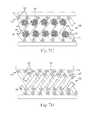
- Figure 7Ais a cross sectional view conductor assembly 150 in which the electrical conductors 152 for the inner coil 154 and the electrical conductors 156 for the outer coil 158 each include a plurality of un-insulated wires 160 surrounded by an insulating layer 162 in accordance with an embodiment of the present disclosure.
- the electrical conductors 152 in the inner coil 154contact the electrical conductors 156 of the outer coil 158 at a plurality of interfaces 164.
- Figure 7Bis a cross sectional view conductor assembly 170 in which the electrical conductors 172 for the outer coil 174 each include a plurality of un-insulated wires 176 surrounded by an insulating layer 178, and the inner coil 180 includes a plurality of insulated electrical conductors 182 each with a single conductive element in accordance with an embodiment of the present disclosure.
- the electrical conductors 172 in the outer coil 174contact the electrical conductors 182 of the inner coil 180 at a plurality of interfaces 184.
- Figure 7Cis a cross sectional view conductor assembly 190 in which the electrical conductors 172 of the outer coil 174 are a plurality of insulated electrical conductors 182 each with a single conductive element and the electrical conductors 182 of the inner coil 180 are a plurality of un-insulated wires 176 surrounded by an insulating layer 178 in accordance with an embodiment of the present disclosure.
- Figure 7Dis a cross sectional view conductor assembly 192 in which the electrical conductors 172, 182 in both the inner and outer coils 180, 174 are a plurality of insulated electrical conductors 182 each with a single conductive element in accordance with an embodiment of the present disclosure. In both embodiments, the electrical conductors 172 in the outer coil 174 contact the electrical conductors 182 of the inner coil 180 at a plurality of interfaces 184.
- Figure 8is a flow chart of a method of making a therapy delivery element adapted for at least partial insertion in a living body in accordance with an embodiment of the present disclosure.
- a plurality of the first electrical conductors each covered with an insulatorare helically wound in a first direction to form an inner coil with a lumen (200).
- a plurality of second electrical conductorsare helically wound in a second opposite direction forming an outer coil in direct physical contact with the inner coil.
- Each of the second electrical conductorsincludes a plurality of un-insulated wires twisted in a ropelike configuration around a central axis to form a cable covered with an insulator (202).
- An insulator coveringis applied to the inner and outer coils to form a lead body (204).
- At least one electrically conductive connectoris attached to a proximal end of the lead body and at least one electrode is attached to a distal end of the lead body (206).
- Each matched set of connectors and electrodesare electrically coupled with one of the first or second electrical conductors (208).
- Figure 9is a flow chart of a method of implanting a neurostimulation system in accordance with an embodiment of the present disclosure.
- a distal end of a stylet wireis inserted into the lumen through an opening at the proximal end of the therapy delivery element of Figure 8 (220).
- the surgeongrasps a stylet handle attached to the stylet wire to steer the electrodes at the distal end of a therapy delivery element to a target location within the living body (222).
- the styletis removed from the therapy delivery element (224).
- An implantable pulse generatoris implanted within the living body (226). Electrical contacts at the proximal end of the therapy delivery element are electrically coupled with the implantable pulse generator (228).
Landscapes
- Health & Medical Sciences (AREA)
- Heart & Thoracic Surgery (AREA)
- Life Sciences & Earth Sciences (AREA)
- Radiology & Medical Imaging (AREA)
- General Health & Medical Sciences (AREA)
- Engineering & Computer Science (AREA)
- Biomedical Technology (AREA)
- Nuclear Medicine, Radiotherapy & Molecular Imaging (AREA)
- Veterinary Medicine (AREA)
- Animal Behavior & Ethology (AREA)
- Cardiology (AREA)
- Public Health (AREA)
- Biophysics (AREA)
- Neurology (AREA)
- Neurosurgery (AREA)
- Orthopedic Medicine & Surgery (AREA)
- Electrotherapy Devices (AREA)
Abstract
Description
- The present disclosure relates to a lead body with inner and outer co-axial coils each having a plurality of discrete electrical paths. The inner and outer coils are in direct physical contact and coiled in opposite directions.
- The human body imposes stringent requirements on electrical conductors that are implanted in it. Leads inserted in a living body that form a part of a stimulation and/or measuring device are subjected to almost continuous flexure during body movement. Also, a living body constitutes a site that is chemically and biologically hostile to anything that invades it. Consequently, leads ideally have good deformability, particularly bending ability, high fatigue resistance, corrosion resistance, and a high degree of electric conductance.
U.S. Pat. No. 4,640,983 (Comte) discloses a lead body having at least one spiral which is formed from at least one conductor. Each conductor consists of wires that are stranded together to form a bundle. The wires belonging to a conductor can all consist of the same material or of different materials, one of which has a large breaking strength and the other one having high electric conductivity. One embodiment discloses inner and outer coils wound in the same direction and separated by an insulating sheath.U.S. Pat. No. 5,483,022 (Mar) discloses a lead body having at least one helical coil formed from at least one electrical cable. Each cable is formed from several wires twisted in a ropelike configuration. Each wire is a composite of a core of a highly conductive material and a coveting of a strong and biocompatible material, with all adjacent wires belonging to the same cable in un-insulated contact with each other. One embodiment discloses inner and outer coils wound in the same direction and separated by an insulating sheath.U.S. Pat. No. 6,978,185 (Osypka) discloses a lead body having electrically active and inactive elements helically wound together. The active elements are separated from each other by the inactive elements. One embodiment discloses inner and outer coils wound in opposite directions and separated by an insulating sheath.- The present disclosure relates to a lead body with inner and outer co-axial coils each having a plurality of discrete electrical paths. The inner and outer coils are coiled in opposite directions and in direct physical contact with each other. Embodiments with twelve discrete electrical paths are disclosed. The conductor device provides a relatively high electric conductance with great flexibility, expandability, breaking strength and, in particular, fatigue resistance.
- One embodiment is directed to a biomedical conductor assembly adapted for at least partial insertion in a living body. The conductor assembly includes a plurality of first and second electrical conductors each covered with an insulator. A plurality of the first electrical conductors are helically wound in a first direction to form an inner coil with a lumen and a plurality of the second electrical connectors helically wound in a second opposite direction forming an outer coil in direct physical contact with the inner coil. An insulator covers the inner and outer coils. The plurality of second electrical conductors each include a plurality of un-insulated wires twisted in a ropelike configuration around a central axis to form a plurality of cables. Each cable is covered with an insulator. The un-insulated wires are preferably movable with respect to each within the insulator.
- The inner coil preferably slides relative to the outer coil within the conductor assembly. The first electrical conductors each optionally include a plurality of discrete insulated wires. The first electrical conductors optionally include a plurality of un-insulated wires twisted in a ropelike configuration around a central axis to form a cable wherein each cable is covered with an insulator.
- In one embodiment, the un-insulated wires in the second electrical conductors include a core of a first material surrounded by a covering of a second material. In another embodiment, the second electrical conductors include a center wire and a plurality of un-insulated wires twisted in a ropelike configuration around the center wire. The center wire preferably has a greater breaking strength than the un-insulated wires.
- The conductor assembly can include any number of discrete conductors. In one embodiment, the inner coil includes four discrete insulated wires and the outer coil includes four or eight discrete insulated cables.
- In another embodiment is directed to a biomedical conductor assembly adapted for at least partial insertion in a living body. The conductor assembly includes a plurality of the first electrical conductors each covered with an insulator and helically wound in a first direction to form an inner coil with a lumen. A plurality of second electrical conductors wound in a second opposite direction forming an outer coil in direct physical contact with the inner coil. The second electrical conductors each including a plurality of un-insulated wires twisted in a ropelike configuration around a central axis to form a plurality of cables covered with an insulator. The inner and outer coils are covered by an insulator.
- The present disclosure is also directed to a therapy delivery element including an elongated lead body having a proximal end and a distal end. The lead body includes a plurality of the first electrical conductors each covered with an insulator and helically wound in a first direction to form an inner coil with a lumen and a plurality of second electrical conductors each including a plurality of un-insulated wires twisted in a ropelike configuration around a central axis to form a plurality of cables. Each cable is covered with an insulator and helically wound in a second opposite direction forming an outer coil in direct physical contact with the inner coil. An insulator covers the inner and outer coils. At least one electrically conductive connector is operatively associated with the proximal end of the lead body and at least one electrode is operatively associated with the distal end of the lead body. Each matched set of connectors and electrodes are electrically coupled with one of the first or second electrical conductors.
- The therapy delivery element preferably includes a stylet wire having a distal end inserted into the lumen through an opening at the proximal end of the lead body and a proximal end attached to a stylet handle.
- The present disclosure is also directed to a neurostimulation system including an implantable pulse generator and a therapy delivery element in accordance with an embodiment of the present disclosure. A stylet wire having a distal end is inserted into the lumen through an opening at the proximal end of the lead body and a proximal end attached to a stylet handle.
- The present disclosure is also directed to a method of making a therapy delivery element adapted for at least partial insertion in a living body. The method includes helically winding a plurality of the first electrical conductors each covered with an insulator in a first direction to form an inner coil with a lumen. A plurality of second electrical conductors is helically wound in a second opposite direction forming an outer coil in direct physical contact with the inner coil. Each of the second electrical conductors includes a plurality of un-insulated wires twisted in a ropelike configuration around a central axis to form a plurality of cables covered with an insulator. An insulating covering is applied to the inner and outer coils to form a lead body. At least one electrically conductive connector is attached to a proximal end of the lead body and at least one electrode is attached to a distal end of the lead body. Each matched set of connectors and electrodes are electrically coupled with one of the first or second electrical conductors.
- The present disclosure is also directed to a method of implanting a neurostimulation system. The method includes grasping a stylet handle attached to a stylet wire inserted into a lumen of a therapy delivery element in accordance with an embodiment of the present disclosure. The electrodes at a distal end of a therapy delivery element are steered to a target location within the living body. The stylet is removed from the therapy delivery element. An implantable pulse generator is implanted within the living body. The electrical contacts at the proximal end of the therapy delivery element are electrically coupled with the implantable pulse generator.
- The present invention may also be directed to the subject-matter according to one or more of the following sections. Further, the features of these sections but also all features of the entire specification may be combined with one another.
- 1. A biomedical conductor assembly adapted for at least partial insertion in a living body, the conductor assembly comprising:
- a plurality of first electrical conductors each covered with an insulator;
- a plurality of second electrical conductors each comprising a plurality of un-insulated wires twisted in a ropelike configuration around a central axis to form a cable, each cable is covered with an insulator, the un-insulated wires are movable with respect to each within the insulator, a plurality of the first electrical conductors are helically wound in a first direction to form an inner coil with a lumen, and a plurality of the second electrical connectors are helically wound in a second opposite direction to form an outer coil in direct physical contact with the inner coil; and
- an insulator covering the inner and outer coils.
- 2. The conductor assembly according to
section 1 wherein the inner coil slides relative to the outer coil within the conductor assembly. - 3. The conductor assembly according to
section - 4. The conductor assembly according to one of the preceding sections
wherein the first electrical conductors comprise a plurality of un-insulated wires that are twisted in a ropelike configuration around a central axis to form a cable wherein each cable is covered with an insulator. - 5. The conductor assembly according to one of the preceding sections
wherein at least one of the un-insulated wires in the second electrical conductors comprise a core of a first material surrounded by a covering of a second material. - 6. The conductor assembly according to one of the preceding sections
wherein the second electrical conductors comprise a center wire of a homogeneous material and a plurality of un-insulated wires that are twisted in a ropelike configuration around the center wire. - 7. The conductor assembly according to one of the preceding sections
wherein the second electrical conductors comprises a plurality of un-insulated wires wrapped around a center wire, where the center wire comprises a greater breaking strength than the un-insulated wires. - 8. The conductor assembly according to one of the preceding sections
wherein the inner coil comprises four discrete insulated wires and the outer coil comprises four or eight discrete insulated cables. - 9. A biomedical conductor assembly adapted for at least partial insertion in a living body, the conductor assembly comprising:
- a plurality of the first electrical conductors that are each covered with an insulator and are helically wound in a first direction to form an inner coil with a lumen;
- a plurality of second electrical conductors that are helically wound in a second opposite direction forming an outer coil in direct physical contact with the inner coil, each of the second electrical conductors comprising a plurality of un-insulated wires twisted in a ropelike configuration around a central axis and covered with an insulator; and
- an insulator covering the inner and outer coils.
- 10. A therapy delivery element comprising:
- an elongated lead body having a proximal end and a distal end, the lead body comprising a plurality of the first electrical conductors are each covered with an insulator and helically wound in a first direction to form an inner coil with a lumen, a plurality of second electrical conductors are each comprising a plurality of un-insulated wires twisted in a ropelike configuration around a central axis to form a plurality of cables, each cable is covered with an insulator and helically wound in a second opposite direction forming an outer coil in direct physical contact with the inner coil, and an insulator covering the inner and outer coils; and
- at least one electrically conductive connector operatively associated with the proximal end of the lead body and at least one electrode operatively associated with the distal end of the lead body, each matched set of connectors and electrodes electrically are coupled with one of the first or second electrical conductors.
- 11. The therapy delivery element according to
section 10 comprising a stylet wire having a distal end insert into the lumen through an opening at the proximal end of the lead body and a proximal end attached to a stylet handle. - 12. A neurostimulation system comprising:
- an implantable pulse generator;
- a therapy delivery element comprising;
an elongated lead body having a proximal end and a distal end, the lead body comprising a plurality of the first electrical conductors that are each covered with an insulator and are helically wound in a first direction to form an inner coil with a lumen, a plurality of second electrical conductors each comprising a plurality of un-insulated wires twisted in a ropelike configuration around a central axis to form a plurality of cables, each cable is covered with an insulator and is helically wound in a second opposite direction forming an outer coil in direct physical contact with the inner coil, and an insulator covering the inner and outer coils;
at least one electrically conductive connector operatively associated with the proximal end of the lead body and at least one electrode operatively associated with the distal end of the lead body, each matched set of connectors and electrodes are electrically coupled with one of the first or second electrical conductors, wherein the connectors are adapted to electrically couple with the implantable pulse generator; and - a stylet wire having a distal end insert into the lumen through an opening at the proximal end of the lead body and a proximal end attached to a stylet handle.
- 13. A method of making a therapy delivery element adapted for at least partial insertion in a living body, the method comprising the steps of:
- helically winding a plurality of the first electrical conductors that are each covered with an insulator in a first direction to form an inner coil with a lumen;
- helically winding a plurality of second electrical conductors in a second opposite direction to form an outer coil in direct physical contact with the inner coil, each of the second electrical conductors comprising a plurality of un-insulated wires twisted in a ropelike configuration around a central axis to form a plurality of cables each covered with an insulator;
- applying an insulator covering to the inner and outer coils to form a lead body; and
- attached at least one electrically conductive connector to a proximal end of the lead body and at least one electrode to a distal end of the lead body, each matched set of connectors and electrodes are electrically coupled with one of the first or second electrical conductors.
- 14. The method according to section 13 wherein the inner coil slides relative to the outer coil within the conductor assembly.
- 15. The method according to
section 13 or 14 wherein the first electrical conductors comprise a plurality of discrete insulated wires. - 16. The method according to one of sections 13 to 15 wherein the first electrical conductors comprise a plurality of un-insulated wires twisted in a ropelike configuration around a central axis to form a cable, each cable covered with an insulator, the un-insulated wires movable with respect to each within the insulator.
- 17. The method according to one of sections 13 to 16 wherein the second electrical conductors comprises a plurality of un-insulated wires wrapped around a center wire, where the center wire comprises a greater breaking strength than the un-insulated wires.
- 18. The method according to one of sections 13 to 17 wherein the inner coil comprises four discrete insulated wires and the outer coil comprises four or eight discrete insulated cables.
- 19. The method according to one of sections 13 to 18 comprising the step of inserting a distal end of a stylet wire into the lumen through an opening at the proximal end of the therapy delivery element.
- 20. The method of implanting a neurostimulation system comprising the steps of:
- grasping a stylet handle attached to the stylet wire according to section 19;
- steering the electrodes at a distal end of a therapy delivery element to a target location within the living body;
- removing the stylet from the therapy delivery element;
- implanting an implantable pulse generator within the living body; and
- electrically coupling the electrical contacts at the proximal end of the therapy delivery element with the implantable pulse generator.
Figure 1 is a schematic illustration of a therapy delivery system.Figure 2 is a schematic illustration of an environment for a therapy delivery system in accordance with an embodiment of the present disclosure.Figure 3 is an alternate illustration of the environment for an implantable pulse generator with a therapy delivery element in accordance with an embodiment of the present disclosure.Figure 4A is a schematic illustration of an implantable pulse generator and a therapy delivery element in accordance with an embodiment of the present disclosure.Figure 4B is a schematic illustration of a lead extension and a therapy delivery element in accordance with an embodiment of the present disclosure.Figure 5A is a schematic illustration of a stylet-lead assembly in accordance with an embodiment of the present disclosure.Figure 5B is an exploded view of the stylet-lead assembly ofFigure 5A .Figures 6A and 6B are sectional views of a lead body in accordance with an embodiment of the present disclosure.Figure 6C is a sectional view of an electrical conductor including a plurality of un-insulated wires in accordance with an embodiment of the present disclosure.Figures 7A - 7D are side sectional views of various conductor assemblies in accordance with an embodiment of the present disclosure.Figure 8 is a flow chart of a method of making a stylet in accordance with an embodiment of the present disclosure.Figure 9 is a flow chart of a method of implanting a neurostimulation system in accordance with an embodiment of the present disclosure.- The description that follows relates to spinal cord stimulation (SCS) system. However, it is to be understood that the while the present disclosure lends itself well to applications in SCS, the disclosure in its broadest aspects may not be so limited. Rather, the disclosure may be used with any type of implantable therapy delivery system with one or more therapy delivery elements. For example, the present disclosure may be used as part of a pacemaker, a defibrillator, a cochlear stimulator, a retinal stimulator, a stimulator configured to produce coordinated limb movement, a cortical stimulator, a deep brain stimulator, peripheral nerve stimulator, microstimulator, or in any other neural stimulator configured to treat urinary incontinence, sleep apnea, shoulder sublaxation, headache, etc.
- In another embodiment, one or more of the therapy delivery elements may be a fluid delivery conduit, such as a catheter, including an inner lumen that is placed to deliver a fluid, such as pharmaceutical agents, insulin, pain relieving agents, gene therapy agents, or the like from a fluid delivery device (e.g., a fluid reservoir and/or pump) to a respective target tissue site in a patient.
- In yet another embodiment, one or more of the therapy delivery elements may be an electrical lead including one or more sensing electrodes to sense physiological parameters (e.g., blood pressure, temperature, cardiac activity, etc.) at a target tissue site within a patient. In the various embodiments contemplated by this disclosure, therapy may include stimulation therapy, sensing or monitoring of one or more physiological parameters, fluid delivery, and the like. "Therapy delivery element" includes pacing or defibrillation leads, stimulation leads, sensing leads, fluid delivery conduit, and any combination thereof. "Target tissue site" refers generally to the target site for implantation of a therapy delivery element, regardless of the type of therapy.
Figures 1 illustrates a generalizedtherapy delivery system 10 that may be used in spinal cord stimulation (SCS), as well as other stimulation applications. Thetherapy delivery system 10 generally includes an implantable pulse generator 12 ("IPG") ("IPG"), an implantabletherapy delivery element 14, which carries an array of electrodes 18 (shown exaggerated for purposes of illustration), and an optionalimplantable extension lead 16. Although only onetherapy delivery element 14 is shown, typically two or moretherapy delivery elements 14 are used with thetherapy delivery system 10.- The
therapy delivery element 14 includeslead body 40 having aproximal end 36 and adistal end 44. Thelead body 40 typically has a diameter of between about 0.03 inches to 0.07 inches and a length within the range of 30 cm to 90 cm for spinal cord stimulation applications. Thelead body 40 may include a suitable electrically insulative costing, such as, a polymer (e.g., polyurethane or silicone). - In the illustrated embodiment,
proximal end 36 of thetherapy delivery element 14 is electrically coupled todistal end 38 of theextension lead 16 via aconnector 20, typically associated with theextension lead 16.Proximal end 42 of theextension lead 16 is electrically coupled to theimplantable pulse generator 12 viaconnector 22 associated withhousing 28. Alternatively, theproximal end 36 of thetherapy delivery element 14 can be electrically coupled directly to theconnector 22. - In the illustrated embodiment, the
implantable pulse generator 12 includes electronic subassembly 24 (shown schematically), which includes control and pulse generation circuitry (not shown) for delivering electrical stimulation energy to theelectrodes 18 of thetherapy delivery element 14 in a controlled manner, and a power supply, such asbattery 26. - The
implantable pulse generator 12 provides a programmable stimulation signal (e.g., in the form of electrical pulses or substantially continuous-time signals) that is delivered to target stimulation sites byelectrodes 18. In applications with more than onetherapy delivery element 14, theimplantable pulse generator 12 may provide the same or a different signal to theelectrodes 18. - Alternatively, the
implantable pulse generator 12 can take the form of an implantable receiver-stimulator in which the power source for powering the implanted receiver, as well as control circuitry to command the receiver-stimulator, are contained in an external controller inductively coupled to the receiver-stimulator via an electromagnetic link. In another embodiment, theimplantable pulse generator 12 can take the form of an external trial stimulator (ETS), which has similar pulse generation circuitry as an IPG, but differs in that it is a non-implantable device that is used on a trial basis after thetherapy delivery element 14 has been implanted and prior to implantation of the IPG, to test the responsiveness of the stimulation that is to be provided. - The
housing 28 is composed of a biocompatible material, such as for example titanium, and forms a hermetically sealed compartment containing theelectronic subassembly 24 andbattery 26 protected from the body tissue and fluids. Theconnector 22 is disposed in a portion of thehousing 28 that is, at least initially, not sealed. Theconnector 22 carries a plurality of contacts that electrically couple with respective terminals at proximal ends of thetherapy delivery element 14 orextension lead 16. Electrical conductors extend from theconnector 22 and connect to theelectronic subassembly 24. Figure 2 illustrates thetherapy delivery element 14 implanted in theepidural space 30 of a patient in close proximity to the dura, the outer layer that surrounds thespinal cord 32, to deliver the intended therapeutic effects of spinal cord electrical stimulation. The target stimulation sites may be anywhere along thespinal cord 32, such as for example proximate the sacral nerves.- Because of the lack of space near the
lead exit point 34 where thetherapy delivery element 14 exits the spinal column, theimplantable pulse generator 12 is generally implanted in a surgically-made pocket either in the abdomen or above the buttocks, such as illustrated inFigure 3 . Theimplantable pulse generator 12 may, of course, also be implanted in other locations of the patient's body. Use of theextension lead 16 facilitates locating theimplantable pulse generator 12 away from thelead exit point 34. In some embodiments, theextension lead 16 serves as a lead adapter if theproximal end 36 of thetherapy delivery element 14 is not compatible with theconnector 22 of theimplantable pulse generator 12, since different manufacturers use different connectors at the ends of their stimulation leads and are not always compatible with theconnector 22. - As illustrated in
Figure 3 , thetherapy delivery system 10 also may include aclinician programmer 46 and apatient programmer 48.Clinician programmer 46 may be a handheld computing device that permits a clinician to program neurostimulation therapy for patient using input keys and a display. For example, usingclinician programmer 46, the clinician may specify neurostimulation parameters for use in delivery of neurostimulation therapy.Clinician programmer 46 supports telemetry (e.g., radio frequency telemetry) with theimplantable pulse generator 12 to download neurostimulation parameters and, optionally, upload operational or physiological data stored byimplantable pulse generator 12. In this manner, the clinician may periodically interrogate theimplantable pulse generator 12 to evaluate efficacy and, if necessary, modify the stimulation parameters. - Similar to
clinician programmer 46,patient programmer 48 may be a handheld computing device.Patient programmer 48 may also include a display and input keys to allow patient to interact withpatient programmer 48 and theimplantable pulse generator 12. Thepatient programmer 48 provides patient with an interface for control of neurostimulation therapy provided by theimplantable pulse generator 12. For example, patient may usepatient programmer 48 to start, stop or adjust neurostimulation therapy. In particular,patient programmer 48 may permit patient to adjust stimulation parameters such as duration, amplitude, pulse width and pulse rate, within an adjustment range specified by the clinician viaclinician programmer 46, or select from a library of stored stimulation therapy programs. - The
implantable pulse generator 12,clinician programmer 46, andpatient programmer 48 may communicate via cables or a wireless communication.Clinician programmer 46 andpatient programmer 48 may, for example, communicate via wireless communication with theimplantable pulse generator 12 using RF telemetry techniques known in the art.Clinician programmer 46 andpatient programmer 48 also may communicate with each other using any of a variety of local wireless communication techniques, such as RF communication according to the 802.11 or Bluetooth specification sets, infrared communication, e.g., according to the IrDA standard, or other standard or proprietary telemetry protocols. Figure 3 also illustrates a general environmental that may benefit from use of a tunneling tool in accordance with an embodiment of the present disclosure. Since theimplantable pulse generator 12 is located remotely fromtarget location 50 for therapy, thetherapy delivery element 14 and/or theextension lead 16 is typically routed through apathway 52 subcutaneously formed along the torso of the patient to asubcutaneous pocket 54 where theimplantable pulse generator 12 is located. As used hereinafter, "lead" and "lead extension" are used interchangeably, unless content clearly dictates otherwise.- The
therapy delivery elements 14 are typically fixed in place near the location selected by the clinician using the present suture anchors 60. The suture anchors 60 can be positioned on thetherapy delivery element 14 in a wide variety of locations and orientations to accommodate individual anatomical differences and the preferences of the clinician. The suture anchors 60 may then be affixed to tissue using fasteners, such as for example, one or more sutures, staples, screws, or other fixation devices. The tissue to which the suture anchors 60 are affixed may include subcutaneous fascia layer, bone, or some other type of tissue. Securing the suture anchors 60 to tissue in this manner prevents or reduces the chance that thetherapy delivery element 14 will become dislodged or will migrate in an undesired manner. Figure 4A illustrates thetherapy delivery element 14 including one or moreelectrical contacts 15 at theproximal end 36, and one ormore electrodes 18 at thedistal end 44. Thecontacts 15 andelectrodes 18 are electrically coupled via insulated wires running through thetherapy delivery element 14.Proximal end 36 of thetherapy delivery element 14 is electrically and mechanically coupled toimplantable pulse generator 12 by theconnector assembly 22.- The
connector assembly 22 includes a plurality ofdiscrete contacts 23 located in thehousing 28 that electrically couple contact rings 15 on the proximal end of thetherapy delivery element 14. Thediscrete contacts 23 are electrically coupled tocircuitry 24 in theimplantable pulse generator 12 byconductive members 21. Eachcontact ring 15 is electrically coupled to one or more of theelectrodes 18 located at thedistal end 44 of thetherapy delivery element 14. Consequently, theimplantable pulse generator 12 can independently deliver electrical impulses to each of theelectrodes 18. - Alternatively, the
therapy delivery element 14 can be coupled to theimplantable pulse generator 12 through one or morelead extensions 16, as illustrated inFigure 4B . Theconnector 20 at thedistal end 38 of thelead extension 16 preferably includes a plurality of thecontacts 23 configured in a manner similar to theconnector assembly 22. Figures 5A and 5B illustrate a stylet/lead assembly 70 including thetherapy delivery element 14 in accordance with an embodiment of the present disclosure. The term stylet refers to a tool inserted into the lumen of a therapy delivery element, such as a neurostimulation lead, to stiffen the lead body and to facilitate its insertion into a target tissue.- In the illustrated embodiment,
stylet 72 includesstylet wire 74 attached to handle 76. Thestylet wire 74 has a diameter smaller than lumen 78 in thelead body 86 of thetherapy delivery element 14.Length 80 is typically the same, or slightly greater than,length 82 of thelumen 78 so thedistal end 84 of thestylet wire 74 preferably reachesdistal end 85 of thetherapy delivery element 14. Thedistal end 85 of the therapy delivery element is typically sealed, so thelength 82 of thelumen 78 is less than the length of thetherapy delivery element 14. In use,distal end 84 of thestylet wire 74 is inserted inlumen 78 of thetherapy delivery element 14 to create the stylet/lead assembly 70. - Conventional stylet wires for the SCS application are typically made of stainless steel or tungsten. Super-elastic materials provide excellent kink resistance but have poor resistance to buckling forces and torque. Consequently, a
stylet wire 74 made from these materials alone is not be suitable for use for SCS therapy delivery elements. Stylet wires manufactured from combinations of linear and super-elastic materials have been evaluated, as disclosed inU.S. Pat. Nos. 6,214,016 ;6,168,571 ;5,238,004 ;6,270,496 and5,957,966 , which are hereby incorporated by reference. Figures 6A and 6B are cut-away views of aconductor assembly 100 for thelead body 86 having aninner coil 102 andouter coil 104 in accordance with an embodiment of the present disclosure. Theinner coil 102 includes a plurality of discreteelectrical conductors 106 each covered with aninsulator 108 and helically wound in afirst direction 110 aroundlumen 78 that receivesstylet wire 74. Theouter coil 104 includes a plurality of discreteelectrical conductors 112 each covered with aninsulator 114 and helically wound in a second opposite direction 116. Theinsulators electrical conductor conductor assembly 100. The pitch of the inner andouter coils Insulator 118 surrounds both the inner andouter coils insulator 118 is preferably a rubber-elastic, bendable and biologically compatible material, such as for example, an elastomer on a polyurethane or silicon base.- The
conductor assembly 100 preferably includes at least oneelectrical conductor electrode 18. In one embodiment, the inner andouter coils electrical conductors inner coil 102 includes fourelectrical conductors 106 and theouter coil 104 includes eightelectrical conductors 112, to support a twelve-electrode lead. Any number ofelectrical conductors present conductor assembly 100 to provide the desired number of circuit paths for the electrodes. - The
inner coil 102 is preferably in direct physical contact with theouter coil 104, reducing the size of theconductor assembly 100 and increasing the density of available circuit paths. Winding theelectrical conductors opposite directions 110, 116 permits movement of theinner coil 102 relative to theouter coil 104 and permits theconductor assembly 100 to be bent with such a small radius of curvature without permanent or lasting deformation. The inner andouter coils conductor assembly 100 to elastically expandable inlongitudinal direction 130. Configuring thecoils lead body 86. The increased torque transfer aids during implantation of thetherapy delivery element 14. - The
electrical conductors Figure 6C , one or more of theelectrical conductors conductive wires 120a-120g (collectively "120") twisted in aropelike configuration 122.Insulator 124 surrounds the conductive wires 120 to form one of theelectrical conductor - In the illustrated embodiment, the six
outer wires 120a-120f are uniformly distributed around thecenter wire 120g. Theouter wires 120a-120f are preferably composites including acore 126 of a first material and a covering 128 of a second material. Thecore 126 preferably has greater electrical conductivity than the covering 128 and the covering 128 preferably has a greater breaking strength and better biocompatibility than thecore 126. For example, thecore 126 can be silver or copper and the covering 128 can be a nickel-cobalt-chromium-molybdenum alloy, such as for example, MP35N. - The
center wire 120g is preferably constructed from a material with a greater breaking strength than the sixouter wires 120a-120f. Thecenter wire 120g can optionally be constructed from a non-conductive material, such as for example a monofilament. In one embodiment, thecenter wire 120g is constructed from the same material as thecovering layer 128. Alternatively, thecenter wire 120g can be one of a variety of alloys, such as the CoNiCrMoWFe alloy (standard ASTM F 563-78) supplied under the commercial name Syntacoben by Institut Straumann AG, Switzerland; the CoCrFeNi alloy supplied under the commercial name Elgiloy by Elgin National Watch Co., U.S.A.; stainless steel, such as the Fe, Cr, Ni, Mo containing steel (standards ISO 5832/1; ASTM F 138-76) commercially available under the designation 316 L; or a variety of other materials disclosed inU.S. Pat. No. 4,640,983 (Comte), which is hereby incorporated by reference. - Bending stress, or flexure stress, varies with position throughout the cross section of the wires 120. Stress is zero at the center of the wires 120, but increases with distance from the center. Since the maximum stress occurs at the surface of the wires 120, using a composite material with the strongest material on the covering 128 provides significant advantage by allowing greater stress without permanent deformation. Since minimal stress occurs in the
core 126 of the wire 120, it is less important that the core material be strong. Figure 7A is a cross sectionalview conductor assembly 150 in which theelectrical conductors 152 for theinner coil 154 and theelectrical conductors 156 for theouter coil 158 each include a plurality ofun-insulated wires 160 surrounded by an insulatinglayer 162 in accordance with an embodiment of the present disclosure. Theelectrical conductors 152 in theinner coil 154 contact theelectrical conductors 156 of theouter coil 158 at a plurality ofinterfaces 164.Figure 7B is a cross sectionalview conductor assembly 170 in which theelectrical conductors 172 for theouter coil 174 each include a plurality ofun-insulated wires 176 surrounded by an insulatinglayer 178, and theinner coil 180 includes a plurality of insulatedelectrical conductors 182 each with a single conductive element in accordance with an embodiment of the present disclosure. Theelectrical conductors 172 in theouter coil 174 contact theelectrical conductors 182 of theinner coil 180 at a plurality ofinterfaces 184.Figure 7C is a cross sectionalview conductor assembly 190 in which theelectrical conductors 172 of theouter coil 174 are a plurality of insulatedelectrical conductors 182 each with a single conductive element and theelectrical conductors 182 of theinner coil 180 are a plurality ofun-insulated wires 176 surrounded by an insulatinglayer 178 in accordance with an embodiment of the present disclosure.Figure 7D is a cross sectionalview conductor assembly 192 in which theelectrical conductors outer coils electrical conductors 182 each with a single conductive element in accordance with an embodiment of the present disclosure. In both embodiments, theelectrical conductors 172 in theouter coil 174 contact theelectrical conductors 182 of theinner coil 180 at a plurality ofinterfaces 184.Figure 8 is a flow chart of a method of making a therapy delivery element adapted for at least partial insertion in a living body in accordance with an embodiment of the present disclosure. A plurality of the first electrical conductors each covered with an insulator are helically wound in a first direction to form an inner coil with a lumen (200). A plurality of second electrical conductors are helically wound in a second opposite direction forming an outer coil in direct physical contact with the inner coil. Each of the second electrical conductors includes a plurality of un-insulated wires twisted in a ropelike configuration around a central axis to form a cable covered with an insulator (202). An insulator covering is applied to the inner and outer coils to form a lead body (204). At least one electrically conductive connector is attached to a proximal end of the lead body and at least one electrode is attached to a distal end of the lead body (206). Each matched set of connectors and electrodes are electrically coupled with one of the first or second electrical conductors (208).Figure 9 is a flow chart of a method of implanting a neurostimulation system in accordance with an embodiment of the present disclosure. A distal end of a stylet wire is inserted into the lumen through an opening at the proximal end of the therapy delivery element ofFigure 8 (220). The surgeon grasps a stylet handle attached to the stylet wire to steer the electrodes at the distal end of a therapy delivery element to a target location within the living body (222). The stylet is removed from the therapy delivery element (224). An implantable pulse generator is implanted within the living body (226). Electrical contacts at the proximal end of the therapy delivery element are electrically coupled with the implantable pulse generator (228).- Where a range of values is provided, it is understood that each intervening value, to the tenth of the unit of the lower limit unless the context clearly dictates otherwise, between the upper and lower limit of that range and any other stated or intervening value in that stated range is encompassed within this disclosure. The upper and lower limits of these smaller ranges which may independently be included in the smaller ranges is also encompassed within the disclosure, subject to any specifically excluded limit in the stated range. Where the stated range includes one or both of the limits, ranges excluding either both of those included limits are also included in the disclosure.
- Unless defined otherwise, all technical and scientific terms used herein have the same meaning as commonly understood by one of ordinary skill in the art to which this disclosure belongs. Although any methods and materials similar or equivalent to those described herein can also be used in the practice or testing of the various methods and materials are now described. All patents and publications mentioned herein, including those cited in the Background of the application, are hereby incorporated by reference to disclose and described the methods and/or materials in connection with which the publications are cited.
- The publications discussed herein are provided solely for their disclosure prior to the filing date of the present application. Nothing herein is to be construed as an admission that the present disclosure is not entitled to antedate such publication by virtue of prior invention. Further, the dates of publication provided may be different from the actual publication dates which may need to be independently confirmed.
- Other embodiments are possible. Although the description above contains much specificity, these should not be construed as limiting the scope of the disclosure, but as merely providing illustrations of some of the presently preferred embodiments. It is also contemplated that various combinations or sub-combinations of the specific features and aspects of the embodiments may be made and still fall within the scope of this disclosure. It should be understood that various features and aspects of the disclosed embodiments can be combined with or substituted for one another in order to form varying modes disclosed. Thus, it is intended that the scope of at least some of the present disclosure should not be limited by the particular disclosed embodiments described above.
- Thus the scope of this disclosure should be determined by the appended claims and their legal equivalents. Therefore, it will be appreciated that the scope of the present disclosure fully encompasses other embodiments which may become obvious to those skilled in the art, and that the scope of the present disclosure is accordingly to be limited by nothing other than the appended claims, in which reference to an element in the singular is not intended to mean "one and only one" unless explicitly so stated, but rather "one or more." All structural, chemical, and functional equivalents to the elements of the above-described preferred embodiment that are known to those of ordinary skill in the art are expressly incorporated herein by reference and are intended to be encompassed by the present claims. Moreover, it is not necessary for a device or method to address each and every problem sought to be solved by the present disclosure, for it to be encompassed by the present claims. Furthermore, no element, component, or method step in the present disclosure is intended to be dedicated to the public regardless of whether the element, component, or method step is explicitly recited in the claims.
Claims (15)
- A biomedical conductor assembly adapted for at least partial insertion in a living body, the conductor assembly comprising:a plurality of first electrical conductors each covered with an insulator;a plurality of second electrical conductors each comprising a plurality of un-insulated wires twisted in a ropelike configuration around a central axis to form a cable, each cable is covered with an insulator, the un-insulated wires are movable with respect to each within the insulator, a plurality of the first electrical conductors are helically wound in a first direction to form an inner coil with a lumen, and a plurality of the second electrical connectors are helically wound in a second opposite direction to form an outer coil in direct physical contact with the inner coil; andan insulator covering the inner and outer coils.
- The conductor assembly according to claim 1
wherein the inner coil slides relative to the outer coil within the conductor assembly, and/or
wherein the first electrical conductors comprise a plurality of discrete insulated wires. - The conductor assembly according to claim 1 or 2
wherein the first electrical conductors comprise a plurality of un-insulated wires that are twisted in a ropelike configuration around a central axis to form a cable wherein each cable is covered with an insulator, and/or
wherein at least one of the un-insulated wires in the second electrical conductors comprise a core of a first material surrounded by a covering of a second material. - The conductor assembly according to one of the preceding claims
wherein the second electrical conductors comprise a center wire of a homogeneous material and a plurality of un-insulated wires that are twisted in a ropelike configuration around the center wire, and/or
wherein the second electrical conductors comprises a plurality of un-insulated wires wrapped around a center wire, where the center wire comprises a greater breaking strength than the un-insulated wires. - The conductor assembly according to one of the preceding claims wherein the inner coil comprises four discrete insulated wires and the outer coil comprises four or eight discrete insulated cables.
- A biomedical conductor assembly adapted for at least partial insertion in a living body, the conductor assembly comprising:a plurality of the first electrical conductors that are each covered with an insulator and are helically wound in a first direction to form an inner coil with a lumen;a plurality of second electrical conductors that are helically wound in a second opposite direction forming an outer coil in direct physical contact with the inner coil, each of the second electrical conductors comprising a plurality of un-insulated wires twisted in a ropelike configuration around a central axis and covered with an insulator; andan insulator covering the inner and outer coils.
- A therapy delivery element comprising:an elongated lead body having a proximal end and a distal end, the lead body comprising a plurality of the first electrical conductors are each covered with an insulator and helically wound in a first direction to form an inner coil with a lumen, a plurality of second electrical conductors are each comprising a plurality of un-insulated wires twisted in a ropelike configuration around a central axis to form a plurality of cables, each cable is covered with an insulator and helically wound in a second opposite direction forming an outer coil in direct physical contact with the inner coil, and an insulator covering the inner and outer coils; andat least one electrically conductive connector operatively associated with the proximal end of the lead body and at least one electrode operatively associated with the distal end of the lead body, each matched set of connectors and electrodes electrically are coupled with one of the first or second electrical conductors.
- The therapy delivery element according to claim 7 comprising a stylet wire having a distal end insert into the lumen through an opening at the proximal end of the lead body and a proximal end attached to a stylet handle.
- A neurostimulation system comprising:an implantable pulse generator;a therapy delivery element comprising;
an elongated lead body having a proximal end and a distal end, the lead body comprising a plurality of the first electrical conductors that are each covered with an insulator and are helically wound in a first direction to form an inner coil with a lumen, a plurality of second electrical conductors each comprising a plurality of un-insulated wires twisted in a ropelike configuration around a central axis to form a plurality of cables, each cable is covered with an insulator and is helically wound in a second opposite direction forming an outer coil in direct physical contact with the inner coil, and an insulator covering the inner and outer coils;
at least one electrically conductive connector operatively associated with the proximal end of the lead body and at least one electrode operatively associated with the distal end of the lead body, each matched set of connectors and electrodes are electrically coupled with one of the first or second electrical conductors, wherein the connectors are adapted to electrically couple with the implantable pulse generator; anda stylet wire having a distal end insert into the lumen through an opening at the proximal end of the lead body and a proximal end attached to a stylet handle. - A method of making a therapy delivery element adapted for at least partial insertion in a living body, the method comprising the steps of:helically winding a plurality of the first electrical conductors that are each covered with an insulator in a first direction to form an inner coil with a lumen;helically winding a plurality of second electrical conductors in a second opposite direction to form an outer coil in direct physical contact with the inner coil, each of the second electrical conductors comprising a plurality of un-insulated wires twisted in a ropelike configuration around a central axis to form a plurality of cables each covered with an insulator;applying an insulator covering to the inner and outer coils to form a lead body; andattached at least one electrically conductive connector to a proximal end of the lead body and at least one electrode to a distal end of the lead body, each matched set of connectors and electrodes are electrically coupled with one of the first or second electrical conductors.
- The method according to claim 10 wherein the inner coil slides relative to the outer coil within the conductor assembly.
- The method according to claim 10 or 11 wherein the first electrical conductors comprise a plurality of discrete insulated wires.
- The method according to one of claims 10 to 12
wherein the first electrical conductors comprise a plurality of un-insulated wires twisted in a ropelike configuration around a central axis to form a cable, each cable covered with an insulator, the un-insulated wires movable with respect to each within the insulator, and/or
wherein the second electrical conductors comprises a plurality of un-insulated wires wrapped around a center wire, where the center wire comprises a greater breaking strength than the un-insulated wires. - The method according to one of claims 10 to 13 wherein the inner coil comprises four discrete insulated wires and the outer coil comprises four or eight discrete insulated cables.
- The method according to one of claims 10 to 14 comprising the step of inserting a distal end of a stylet wire into the lumen through an opening at the proximal end of the therapy delivery element.
Applications Claiming Priority (1)
| Application Number | Priority Date | Filing Date | Title |
|---|---|---|---|
| US13/220,913US8560084B2 (en) | 2011-08-30 | 2011-08-30 | Lead body with inner and outer co-axial coils |
Publications (2)
| Publication Number | Publication Date |
|---|---|
| EP2564892A1true EP2564892A1 (en) | 2013-03-06 |
| EP2564892B1 EP2564892B1 (en) | 2014-10-15 |
Family
ID=46245894
Family Applications (1)
| Application Number | Title | Priority Date | Filing Date |
|---|---|---|---|
| EP12171266.5AActiveEP2564892B1 (en) | 2011-08-30 | 2012-06-08 | Lead body with inner and outer co-axial coils |
Country Status (2)
| Country | Link |
|---|---|
| US (2) | US8560084B2 (en) |
| EP (1) | EP2564892B1 (en) |
Cited By (2)
| Publication number | Priority date | Publication date | Assignee | Title |
|---|---|---|---|---|
| WO2020023012A1 (en)* | 2018-07-23 | 2020-01-30 | Advanced Bionics Ag | Reinforced electrode leads and methods for manufacturing the same |
| WO2023016973A1 (en)* | 2021-08-10 | 2023-02-16 | Biotronik Se & Co. Kg | Braid-supported helical leads for implantable electrode leads |
Families Citing this family (25)
| Publication number | Priority date | Publication date | Assignee | Title |
|---|---|---|---|---|
| EP2719422B1 (en)* | 2012-10-12 | 2015-02-18 | Sorin CRM SAS | Implantable multipolar detection/stimulation microprobe |
| PL2948115T3 (en) | 2013-01-25 | 2018-02-28 | Med-El Elektromedizinische Geraete Gmbh | Impact protection for implantable electric lead |
| US9770598B2 (en)* | 2014-08-29 | 2017-09-26 | Boston Scientific Neuromodulation Corporation | Systems and methods for making and using improved connector contacts for electrical stimulation systems |
| US9956394B2 (en) | 2015-09-10 | 2018-05-01 | Boston Scientific Neuromodulation Corporation | Connectors for electrical stimulation systems and methods of making and using |
| US10342983B2 (en) | 2016-01-14 | 2019-07-09 | Boston Scientific Neuromodulation Corporation | Systems and methods for making and using connector contact arrays for electrical stimulation systems |
| US10201713B2 (en) | 2016-06-20 | 2019-02-12 | Boston Scientific Neuromodulation Corporation | Threaded connector assembly and methods of making and using the same |
| US10307602B2 (en) | 2016-07-08 | 2019-06-04 | Boston Scientific Neuromodulation Corporation | Threaded connector assembly and methods of making and using the same |
| US10543374B2 (en) | 2016-09-30 | 2020-01-28 | Boston Scientific Neuromodulation Corporation | Connector assemblies with bending limiters for electrical stimulation systems and methods of making and using same |
| US10905871B2 (en) | 2017-01-27 | 2021-02-02 | Boston Scientific Neuromodulation Corporation | Lead assemblies with arrangements to confirm alignment between terminals and contacts |
| US10814136B2 (en) | 2017-02-28 | 2020-10-27 | Boston Scientific Neuromodulation Corporation | Toolless connector for latching stimulation leads and methods of making and using |
| US10603499B2 (en) | 2017-04-07 | 2020-03-31 | Boston Scientific Neuromodulation Corporation | Tapered implantable lead and connector interface and methods of making and using |
| WO2019023067A1 (en) | 2017-07-25 | 2019-01-31 | Boston Scientific Neuromodulation Corporation | Systems and methods for making and using an enhanced connector of an electrical stimulation system |
| US11045656B2 (en) | 2017-09-15 | 2021-06-29 | Boston Scientific Neuromodulation Corporation | Biased lead connector for operating room cable assembly and methods of making and using |
| US10639485B2 (en) | 2017-09-15 | 2020-05-05 | Boston Scientific Neuromodulation Corporation | Actuatable lead connector for an operating room cable assembly and methods of making and using |
| US11139603B2 (en) | 2017-10-03 | 2021-10-05 | Boston Scientific Neuromodulation Corporation | Connectors with spring contacts for electrical stimulation systems and methods of making and using same |
| US11103712B2 (en) | 2018-01-16 | 2021-08-31 | Boston Scientific Neuromodulation Corporation | Connector assemblies with novel spacers for electrical stimulation systems and methods of making and using same |
| WO2019165108A1 (en)* | 2018-02-22 | 2019-08-29 | Axonics Modulation Technologies, Inc. | Neurostimulation leads for trial nerve stimulation and methods of use |
| US11052259B2 (en) | 2018-05-11 | 2021-07-06 | Boston Scientific Neuromodulation Corporation | Connector assembly for an electrical stimulation system and methods of making and using |
| USD934438S1 (en) | 2018-06-29 | 2021-10-26 | Spr Therapeutics, Inc. | Lead placement tool |
| US11357992B2 (en) | 2019-05-03 | 2022-06-14 | Boston Scientific Neuromodulation Corporation | Connector assembly for an electrical stimulation system and methods of making and using |
| US12115380B2 (en)* | 2019-10-11 | 2024-10-15 | Medtronic, Inc. | Medical device with braided tubular body |
| US12420103B1 (en) | 2020-08-20 | 2025-09-23 | Axonics, Inc. | Neurostimulation leads with reduced current leakage |
| US12343547B2 (en) | 2021-08-19 | 2025-07-01 | Boston Scientific Neuromodulation Corporation | Connectors for an electrical stimulation system and methods of making and using |
| CN216258739U (en)* | 2021-10-19 | 2022-04-12 | 苏州景昱医疗器械有限公司 | Implantable medical device and its medical lead |
| WO2025120577A1 (en)* | 2023-12-07 | 2025-06-12 | Cochlear Limited | Implantable assembly with reinforcement element |
Citations (12)
| Publication number | Priority date | Publication date | Assignee | Title |
|---|---|---|---|---|
| US4640983A (en) | 1984-04-09 | 1987-02-03 | Institut Straumann Ag | Conductor device, particularly for at least partial insertion in a human or animal body, comprising a spiral formed from at least one conductor |
| US4964414A (en)* | 1987-08-27 | 1990-10-23 | Yasunobu Handa | Electrode for use in implanting in a living body |
| US5238004A (en) | 1990-04-10 | 1993-08-24 | Boston Scientific Corporation | High elongation linear elastic guidewire |
| US5246014A (en)* | 1991-11-08 | 1993-09-21 | Medtronic, Inc. | Implantable lead system |
| US5483022A (en) | 1994-04-12 | 1996-01-09 | Ventritex, Inc. | Implantable conductor coil formed from cabled composite wire |
| US5760341A (en)* | 1996-09-10 | 1998-06-02 | Medtronic, Inc. | Conductor cable for biomedical lead |
| US5957966A (en) | 1998-02-18 | 1999-09-28 | Intermedics Inc. | Implantable cardiac lead with multiple shape memory polymer structures |
| US6168571B1 (en) | 1997-04-15 | 2001-01-02 | Symbiosis Corporation | Linear elastic member |
| US6214016B1 (en) | 1999-04-29 | 2001-04-10 | Medtronic, Inc. | Medical instrument positioning device internal to a catheter or lead and method of use |
| US6270496B1 (en) | 1998-05-05 | 2001-08-07 | Cardiac Pacemakers, Inc. | Steerable catheter with preformed distal shape and method for use |
| US6978185B2 (en) | 2001-11-09 | 2005-12-20 | Oscor Inc. | Multifilar conductor for cardiac leads |
| US20100137928A1 (en)* | 2008-11-07 | 2010-06-03 | Duncan Jeffrey B | Implantable lead |
Family Cites Families (12)
| Publication number | Priority date | Publication date | Assignee | Title |
|---|---|---|---|---|
| EP0312495A3 (en)* | 1987-10-16 | 1989-08-30 | Institut Straumann Ag | Electrical cable for carrying out at least one stimulation and/or measurement in a human or animal body |
| US5330521A (en) | 1992-06-29 | 1994-07-19 | Cohen Donald M | Low resistance implantable electrical leads |
| US6295476B1 (en) | 1999-11-01 | 2001-09-25 | Medtronic, Inc. | Medical lead conductor fracture visualization method and apparatus |
| US6456888B1 (en) | 2000-08-18 | 2002-09-24 | Cardiac Pacemakers, Inc. | Geometry for coupling and electrode to a conductor |
| US6671544B2 (en) | 2001-06-28 | 2003-12-30 | Medtronic, Inc. | Low impedance implantable extension for a neurological electrical stimulator |
| US6671554B2 (en) | 2001-09-07 | 2003-12-30 | Medtronic Minimed, Inc. | Electronic lead for a medical implant device, method of making same, and method and apparatus for inserting same |
| US6920361B2 (en) | 2003-02-14 | 2005-07-19 | Medtronic, Inc. | Reverse wound electrodes |
| US7831311B2 (en) | 2004-10-21 | 2010-11-09 | Medtronic, Inc. | Reduced axial stiffness implantable medical lead |
| US7168165B2 (en) | 2005-03-07 | 2007-01-30 | Medtronic, Inc. | Fabrication of electrical medical leads employing multi-filar wire conductors |
| US8825180B2 (en) | 2005-03-31 | 2014-09-02 | Medtronic, Inc. | Medical electrical lead with co-radial multi-conductor coil |
| US9901731B2 (en) | 2006-01-31 | 2018-02-27 | Medtronic, Inc. | Medical electrical lead having improved inductance |
| EP1935449B1 (en) | 2006-12-19 | 2011-10-19 | Greatbatch Ltd. | Braided electrical lead |
- 2011
- 2011-08-30USUS13/220,913patent/US8560084B2/enactiveActive
- 2012
- 2012-06-08EPEP12171266.5Apatent/EP2564892B1/enactiveActive
- 2013
- 2013-09-12USUS14/024,668patent/US9002476B2/enactiveActive
Patent Citations (12)
| Publication number | Priority date | Publication date | Assignee | Title |
|---|---|---|---|---|
| US4640983A (en) | 1984-04-09 | 1987-02-03 | Institut Straumann Ag | Conductor device, particularly for at least partial insertion in a human or animal body, comprising a spiral formed from at least one conductor |
| US4964414A (en)* | 1987-08-27 | 1990-10-23 | Yasunobu Handa | Electrode for use in implanting in a living body |
| US5238004A (en) | 1990-04-10 | 1993-08-24 | Boston Scientific Corporation | High elongation linear elastic guidewire |
| US5246014A (en)* | 1991-11-08 | 1993-09-21 | Medtronic, Inc. | Implantable lead system |
| US5483022A (en) | 1994-04-12 | 1996-01-09 | Ventritex, Inc. | Implantable conductor coil formed from cabled composite wire |
| US5760341A (en)* | 1996-09-10 | 1998-06-02 | Medtronic, Inc. | Conductor cable for biomedical lead |
| US6168571B1 (en) | 1997-04-15 | 2001-01-02 | Symbiosis Corporation | Linear elastic member |
| US5957966A (en) | 1998-02-18 | 1999-09-28 | Intermedics Inc. | Implantable cardiac lead with multiple shape memory polymer structures |
| US6270496B1 (en) | 1998-05-05 | 2001-08-07 | Cardiac Pacemakers, Inc. | Steerable catheter with preformed distal shape and method for use |
| US6214016B1 (en) | 1999-04-29 | 2001-04-10 | Medtronic, Inc. | Medical instrument positioning device internal to a catheter or lead and method of use |
| US6978185B2 (en) | 2001-11-09 | 2005-12-20 | Oscor Inc. | Multifilar conductor for cardiac leads |
| US20100137928A1 (en)* | 2008-11-07 | 2010-06-03 | Duncan Jeffrey B | Implantable lead |
Cited By (5)
| Publication number | Priority date | Publication date | Assignee | Title |
|---|---|---|---|---|
| WO2020023012A1 (en)* | 2018-07-23 | 2020-01-30 | Advanced Bionics Ag | Reinforced electrode leads and methods for manufacturing the same |
| US20210322763A1 (en)* | 2018-07-23 | 2021-10-21 | Advanced Bionics Ag | Reinforced electrode leads and methods for manufacturing the same |
| US11691003B2 (en) | 2018-07-23 | 2023-07-04 | Advanced Bionics Ag | Reinforced electrode leads and methods for manufacturing the same |
| US12290679B2 (en) | 2018-07-23 | 2025-05-06 | Advanced Bionics Ag | Reinforced electrode leads and methods for manufacturing the same |
| WO2023016973A1 (en)* | 2021-08-10 | 2023-02-16 | Biotronik Se & Co. Kg | Braid-supported helical leads for implantable electrode leads |
Also Published As
| Publication number | Publication date |
|---|---|
| US8560084B2 (en) | 2013-10-15 |
| US9002476B2 (en) | 2015-04-07 |
| US20140018895A1 (en) | 2014-01-16 |
| US20130053864A1 (en) | 2013-02-28 |
| EP2564892B1 (en) | 2014-10-15 |
Similar Documents
| Publication | Publication Date | Title |
|---|---|---|
| US8560084B2 (en) | Lead body with inner and outer co-axial coils | |
| US10661077B2 (en) | Manufacturing method of a dynamic coil for implantable stimulation leads | |
| US8738153B2 (en) | Implantable lead with braided conductors | |
| US11160974B2 (en) | Neurostimulation lead with stiffened proximal array | |
| US11020586B2 (en) | Distally curved electrical stimulation lead and methods of making and using | |
| US9833611B2 (en) | Systems and methods for making and using improved contact arrays for electrical stimulation systems | |
| EP2593178B1 (en) | Tunneling tool for implantable leads | |
| US6671544B2 (en) | Low impedance implantable extension for a neurological electrical stimulator | |
| US8718790B2 (en) | Systems and methods for providing electrical stimulation of multiple dorsal root ganglia with a single lead | |
| US20120232626A1 (en) | Anchor sleeve for implantable lead | |
| US9067056B2 (en) | Lead spacer tool | |
| US9320888B2 (en) | Adjustable wire length stylet handle | |
| US10179234B2 (en) | Distally reinforced lead and methods of making and using | |
| AU2022210245B2 (en) | Electrical stimulation cuff devices and systems with directional electrode configurations | |
| US10124161B2 (en) | Neurostimulation lead with conductive elements and methods for making the same |
Legal Events
| Date | Code | Title | Description |
|---|---|---|---|
| PUAI | Public reference made under article 153(3) epc to a published international application that has entered the european phase | Free format text:ORIGINAL CODE: 0009012 | |
| AK | Designated contracting states | Kind code of ref document:A1 Designated state(s):AL AT BE BG CH CY CZ DE DK EE ES FI FR GB GR HR HU IE IS IT LI LT LU LV MC MK MT NL NO PL PT RO RS SE SI SK SM TR | |
| AX | Request for extension of the european patent | Extension state:BA ME | |
| 17P | Request for examination filed | Effective date:20130325 | |
| RIC1 | Information provided on ipc code assigned before grant | Ipc:A61N 1/05 20060101AFI20131219BHEP Ipc:H01B 7/04 20060101ALI20131219BHEP | |
| GRAP | Despatch of communication of intention to grant a patent | Free format text:ORIGINAL CODE: EPIDOSNIGR1 | |
| INTG | Intention to grant announced | Effective date:20140212 | |
| GRAP | Despatch of communication of intention to grant a patent | Free format text:ORIGINAL CODE: EPIDOSNIGR1 | |
| INTG | Intention to grant announced | Effective date:20140526 | |
| GRAS | Grant fee paid | Free format text:ORIGINAL CODE: EPIDOSNIGR3 | |
| GRAA | (expected) grant | Free format text:ORIGINAL CODE: 0009210 | |
| AK | Designated contracting states | Kind code of ref document:B1 Designated state(s):AL AT BE BG CH CY CZ DE DK EE ES FI FR GB GR HR HU IE IS IT LI LT LU LV MC MK MT NL NO PL PT RO RS SE SI SK SM TR | |
| REG | Reference to a national code | Ref country code:CH Ref legal event code:EP Ref country code:GB Ref legal event code:FG4D | |
| REG | Reference to a national code | Ref country code:IE Ref legal event code:FG4D | |
| REG | Reference to a national code | Ref country code:AT Ref legal event code:REF Ref document number:691341 Country of ref document:AT Kind code of ref document:T Effective date:20141115 | |
| REG | Reference to a national code | Ref country code:DE Ref legal event code:R096 Ref document number:602012003395 Country of ref document:DE Effective date:20141127 | |
| REG | Reference to a national code | Ref country code:NL Ref legal event code:VDEP Effective date:20141015 | |
| REG | Reference to a national code | Ref country code:AT Ref legal event code:MK05 Ref document number:691341 Country of ref document:AT Kind code of ref document:T Effective date:20141015 | |
| REG | Reference to a national code | Ref country code:LT Ref legal event code:MG4D | |
| PG25 | Lapsed in a contracting state [announced via postgrant information from national office to epo] | Ref country code:NL Free format text:LAPSE BECAUSE OF FAILURE TO SUBMIT A TRANSLATION OF THE DESCRIPTION OR TO PAY THE FEE WITHIN THE PRESCRIBED TIME-LIMIT Effective date:20141015 | |
| PG25 | Lapsed in a contracting state [announced via postgrant information from national office to epo] | Ref country code:FI Free format text:LAPSE BECAUSE OF FAILURE TO SUBMIT A TRANSLATION OF THE DESCRIPTION OR TO PAY THE FEE WITHIN THE PRESCRIBED TIME-LIMIT Effective date:20141015 Ref country code:PT Free format text:LAPSE BECAUSE OF FAILURE TO SUBMIT A TRANSLATION OF THE DESCRIPTION OR TO PAY THE FEE WITHIN THE PRESCRIBED TIME-LIMIT Effective date:20150216 Ref country code:NO Free format text:LAPSE BECAUSE OF FAILURE TO SUBMIT A TRANSLATION OF THE DESCRIPTION OR TO PAY THE FEE WITHIN THE PRESCRIBED TIME-LIMIT Effective date:20150115 Ref country code:ES Free format text:LAPSE BECAUSE OF FAILURE TO SUBMIT A TRANSLATION OF THE DESCRIPTION OR TO PAY THE FEE WITHIN THE PRESCRIBED TIME-LIMIT Effective date:20141015 Ref country code:LT Free format text:LAPSE BECAUSE OF FAILURE TO SUBMIT A TRANSLATION OF THE DESCRIPTION OR TO PAY THE FEE WITHIN THE PRESCRIBED TIME-LIMIT Effective date:20141015 Ref country code:IS Free format text:LAPSE BECAUSE OF FAILURE TO SUBMIT A TRANSLATION OF THE DESCRIPTION OR TO PAY THE FEE WITHIN THE PRESCRIBED TIME-LIMIT Effective date:20150215 | |
| PG25 | Lapsed in a contracting state [announced via postgrant information from national office to epo] | Ref country code:GR Free format text:LAPSE BECAUSE OF FAILURE TO SUBMIT A TRANSLATION OF THE DESCRIPTION OR TO PAY THE FEE WITHIN THE PRESCRIBED TIME-LIMIT Effective date:20150116 Ref country code:PL Free format text:LAPSE BECAUSE OF FAILURE TO SUBMIT A TRANSLATION OF THE DESCRIPTION OR TO PAY THE FEE WITHIN THE PRESCRIBED TIME-LIMIT Effective date:20141015 Ref country code:RS Free format text:LAPSE BECAUSE OF FAILURE TO SUBMIT A TRANSLATION OF THE DESCRIPTION OR TO PAY THE FEE WITHIN THE PRESCRIBED TIME-LIMIT Effective date:20141015 Ref country code:CY Free format text:LAPSE BECAUSE OF FAILURE TO SUBMIT A TRANSLATION OF THE DESCRIPTION OR TO PAY THE FEE WITHIN THE PRESCRIBED TIME-LIMIT Effective date:20141015 Ref country code:AT Free format text:LAPSE BECAUSE OF FAILURE TO SUBMIT A TRANSLATION OF THE DESCRIPTION OR TO PAY THE FEE WITHIN THE PRESCRIBED TIME-LIMIT Effective date:20141015 Ref country code:HR Free format text:LAPSE BECAUSE OF FAILURE TO SUBMIT A TRANSLATION OF THE DESCRIPTION OR TO PAY THE FEE WITHIN THE PRESCRIBED TIME-LIMIT Effective date:20141015 Ref country code:SE Free format text:LAPSE BECAUSE OF FAILURE TO SUBMIT A TRANSLATION OF THE DESCRIPTION OR TO PAY THE FEE WITHIN THE PRESCRIBED TIME-LIMIT Effective date:20141015 Ref country code:LV Free format text:LAPSE BECAUSE OF FAILURE TO SUBMIT A TRANSLATION OF THE DESCRIPTION OR TO PAY THE FEE WITHIN THE PRESCRIBED TIME-LIMIT Effective date:20141015 | |
| REG | Reference to a national code | Ref country code:FR Ref legal event code:PLFP Year of fee payment:4 | |
| REG | Reference to a national code | Ref country code:DE Ref legal event code:R097 Ref document number:602012003395 Country of ref document:DE | |
| PG25 | Lapsed in a contracting state [announced via postgrant information from national office to epo] | Ref country code:RO Free format text:LAPSE BECAUSE OF FAILURE TO SUBMIT A TRANSLATION OF THE DESCRIPTION OR TO PAY THE FEE WITHIN THE PRESCRIBED TIME-LIMIT Effective date:20141015 Ref country code:SK Free format text:LAPSE BECAUSE OF FAILURE TO SUBMIT A TRANSLATION OF THE DESCRIPTION OR TO PAY THE FEE WITHIN THE PRESCRIBED TIME-LIMIT Effective date:20141015 Ref country code:EE Free format text:LAPSE BECAUSE OF FAILURE TO SUBMIT A TRANSLATION OF THE DESCRIPTION OR TO PAY THE FEE WITHIN THE PRESCRIBED TIME-LIMIT Effective date:20141015 Ref country code:CZ Free format text:LAPSE BECAUSE OF FAILURE TO SUBMIT A TRANSLATION OF THE DESCRIPTION OR TO PAY THE FEE WITHIN THE PRESCRIBED TIME-LIMIT Effective date:20141015 Ref country code:DK Free format text:LAPSE BECAUSE OF FAILURE TO SUBMIT A TRANSLATION OF THE DESCRIPTION OR TO PAY THE FEE WITHIN THE PRESCRIBED TIME-LIMIT Effective date:20141015 | |
| PLBE | No opposition filed within time limit | Free format text:ORIGINAL CODE: 0009261 | |
| STAA | Information on the status of an ep patent application or granted ep patent | Free format text:STATUS: NO OPPOSITION FILED WITHIN TIME LIMIT | |
| PG25 | Lapsed in a contracting state [announced via postgrant information from national office to epo] | Ref country code:IT Free format text:LAPSE BECAUSE OF FAILURE TO SUBMIT A TRANSLATION OF THE DESCRIPTION OR TO PAY THE FEE WITHIN THE PRESCRIBED TIME-LIMIT Effective date:20141015 | |
| 26N | No opposition filed | Effective date:20150716 | |
| PG25 | Lapsed in a contracting state [announced via postgrant information from national office to epo] | Ref country code:MC Free format text:LAPSE BECAUSE OF FAILURE TO SUBMIT A TRANSLATION OF THE DESCRIPTION OR TO PAY THE FEE WITHIN THE PRESCRIBED TIME-LIMIT Effective date:20141015 | |
| REG | Reference to a national code | Ref country code:CH Ref legal event code:PL | |
| PG25 | Lapsed in a contracting state [announced via postgrant information from national office to epo] | Ref country code:LU Free format text:LAPSE BECAUSE OF FAILURE TO SUBMIT A TRANSLATION OF THE DESCRIPTION OR TO PAY THE FEE WITHIN THE PRESCRIBED TIME-LIMIT Effective date:20150608 Ref country code:SI Free format text:LAPSE BECAUSE OF FAILURE TO SUBMIT A TRANSLATION OF THE DESCRIPTION OR TO PAY THE FEE WITHIN THE PRESCRIBED TIME-LIMIT Effective date:20141015 | |
| REG | Reference to a national code | Ref country code:IE Ref legal event code:MM4A | |
| REG | Reference to a national code | Ref country code:GB Ref legal event code:732E Free format text:REGISTERED BETWEEN 20160324 AND 20160330 | |
| REG | Reference to a national code | Ref country code:DE Ref legal event code:R081 Ref document number:602012003395 Country of ref document:DE Owner name:QIG GROUP, LLC, CLARENCE, US Free format text:FORMER OWNER: GREATBATCH LTD., CLARENCE, N.Y., US | |
| PG25 | Lapsed in a contracting state [announced via postgrant information from national office to epo] | Ref country code:LI Free format text:LAPSE BECAUSE OF NON-PAYMENT OF DUE FEES Effective date:20150630 Ref country code:CH Free format text:LAPSE BECAUSE OF NON-PAYMENT OF DUE FEES Effective date:20150630 Ref country code:IE Free format text:LAPSE BECAUSE OF NON-PAYMENT OF DUE FEES Effective date:20150608 | |
| REG | Reference to a national code | Ref country code:FR Ref legal event code:TP Owner name:QIG GROUP, LLC, US Effective date:20160502 | |
| REG | Reference to a national code | Ref country code:FR Ref legal event code:PLFP Year of fee payment:5 | |
| PG25 | Lapsed in a contracting state [announced via postgrant information from national office to epo] | Ref country code:MT Free format text:LAPSE BECAUSE OF FAILURE TO SUBMIT A TRANSLATION OF THE DESCRIPTION OR TO PAY THE FEE WITHIN THE PRESCRIBED TIME-LIMIT Effective date:20141015 | |
| PG25 | Lapsed in a contracting state [announced via postgrant information from national office to epo] | Ref country code:BG Free format text:LAPSE BECAUSE OF FAILURE TO SUBMIT A TRANSLATION OF THE DESCRIPTION OR TO PAY THE FEE WITHIN THE PRESCRIBED TIME-LIMIT Effective date:20141015 Ref country code:HU Free format text:LAPSE BECAUSE OF FAILURE TO SUBMIT A TRANSLATION OF THE DESCRIPTION OR TO PAY THE FEE WITHIN THE PRESCRIBED TIME-LIMIT; INVALID AB INITIO Effective date:20120608 Ref country code:SM Free format text:LAPSE BECAUSE OF FAILURE TO SUBMIT A TRANSLATION OF THE DESCRIPTION OR TO PAY THE FEE WITHIN THE PRESCRIBED TIME-LIMIT Effective date:20141015 | |
| REG | Reference to a national code | Ref country code:FR Ref legal event code:PLFP Year of fee payment:6 | |
| REG | Reference to a national code | Ref country code:FR Ref legal event code:CA Effective date:20170725 Ref country code:FR Ref legal event code:CD Owner name:NUVECTRA CORPORATION, US Effective date:20170725 Ref country code:FR Ref legal event code:CJ Effective date:20170725 | |
| PG25 | Lapsed in a contracting state [announced via postgrant information from national office to epo] | Ref country code:TR Free format text:LAPSE BECAUSE OF FAILURE TO SUBMIT A TRANSLATION OF THE DESCRIPTION OR TO PAY THE FEE WITHIN THE PRESCRIBED TIME-LIMIT Effective date:20141015 | |
| PG25 | Lapsed in a contracting state [announced via postgrant information from national office to epo] | Ref country code:BE Free format text:LAPSE BECAUSE OF FAILURE TO SUBMIT A TRANSLATION OF THE DESCRIPTION OR TO PAY THE FEE WITHIN THE PRESCRIBED TIME-LIMIT Effective date:20141015 | |
| REG | Reference to a national code | Ref country code:FR Ref legal event code:PLFP Year of fee payment:7 | |
| PG25 | Lapsed in a contracting state [announced via postgrant information from national office to epo] | Ref country code:MK Free format text:LAPSE BECAUSE OF FAILURE TO SUBMIT A TRANSLATION OF THE DESCRIPTION OR TO PAY THE FEE WITHIN THE PRESCRIBED TIME-LIMIT Effective date:20141015 | |
| PG25 | Lapsed in a contracting state [announced via postgrant information from national office to epo] | Ref country code:AL Free format text:LAPSE BECAUSE OF FAILURE TO SUBMIT A TRANSLATION OF THE DESCRIPTION OR TO PAY THE FEE WITHIN THE PRESCRIBED TIME-LIMIT Effective date:20141015 | |
| PGFP | Annual fee paid to national office [announced via postgrant information from national office to epo] | Ref country code:DE Payment date:20250627 Year of fee payment:14 | |
| PGFP | Annual fee paid to national office [announced via postgrant information from national office to epo] | Ref country code:GB Payment date:20250627 Year of fee payment:14 | |
| PGFP | Annual fee paid to national office [announced via postgrant information from national office to epo] | Ref country code:FR Payment date:20250625 Year of fee payment:14 |