EP2564812B1 - Delivery system for an endoluminal prosthesis - Google Patents
Delivery system for an endoluminal prosthesisDownload PDFInfo
- Publication number
- EP2564812B1 EP2564812B1EP12275127.4AEP12275127AEP2564812B1EP 2564812 B1EP2564812 B1EP 2564812B1EP 12275127 AEP12275127 AEP 12275127AEP 2564812 B1EP2564812 B1EP 2564812B1
- Authority
- EP
- European Patent Office
- Prior art keywords
- stent graft
- endoluminal prosthesis
- access port
- delivery system
- trigger wire
- Prior art date
- Legal status (The legal status is an assumption and is not a legal conclusion. Google has not performed a legal analysis and makes no representation as to the accuracy of the status listed.)
- Active
Links
- 238000004891communicationMethods0.000claimsdescription8
- 239000012530fluidSubstances0.000claimsdescription8
- 238000007789sealingMethods0.000description14
- 210000001367arteryAnatomy0.000description11
- 239000000463materialSubstances0.000description11
- 210000003090iliac arteryAnatomy0.000description9
- 230000014759maintenance of locationEffects0.000description8
- 210000000709aortaAnatomy0.000description7
- 239000003356suture materialSubstances0.000description7
- 238000000034methodMethods0.000description6
- 230000000717retained effectEffects0.000description6
- 241001465754MetazoaSpecies0.000description4
- 230000000452restraining effectEffects0.000description4
- 239000000853adhesiveSubstances0.000description3
- 230000001070adhesive effectEffects0.000description3
- 238000002513implantationMethods0.000description3
- 229920001343polytetrafluoroethylenePolymers0.000description3
- 239000004810polytetrafluoroethyleneSubstances0.000description3
- 238000012360testing methodMethods0.000description3
- 239000000560biocompatible materialSubstances0.000description2
- 210000004204blood vesselAnatomy0.000description2
- 210000001105femoral arteryAnatomy0.000description2
- 238000003780insertionMethods0.000description2
- 230000037431insertionEffects0.000description2
- 239000010410layerSubstances0.000description2
- 230000007246mechanismEffects0.000description2
- 229910001000nickel titaniumInorganic materials0.000description2
- 229920000728polyesterPolymers0.000description2
- -1polyethylene terephthalatePolymers0.000description2
- 210000002254renal arteryAnatomy0.000description2
- 230000008439repair processEffects0.000description2
- 238000011477surgical interventionMethods0.000description2
- 206010002329AneurysmDiseases0.000description1
- 206010007269CarcinogenicityDiseases0.000description1
- 241000282412HomoSpecies0.000description1
- 206010061218InflammationDiseases0.000description1
- 230000001154acute effectEffects0.000description1
- 230000002411adverseEffects0.000description1
- 229910045601alloyInorganic materials0.000description1
- 239000000956alloySubstances0.000description1
- 230000000890antigenic effectEffects0.000description1
- 208000007474aortic aneurysmDiseases0.000description1
- 238000012925biological evaluationMethods0.000description1
- 239000008280bloodSubstances0.000description1
- 210000004369bloodAnatomy0.000description1
- 230000017531blood circulationEffects0.000description1
- 231100000260carcinogenicityToxicity0.000description1
- 230000007670carcinogenicityEffects0.000description1
- 239000002131composite materialSubstances0.000description1
- 238000010276constructionMethods0.000description1
- 230000007547defectEffects0.000description1
- 238000013461designMethods0.000description1
- 239000003814drugSubstances0.000description1
- 229940079593drugDrugs0.000description1
- 230000010102embolizationEffects0.000description1
- 210000003238esophagusAnatomy0.000description1
- 238000011156evaluationMethods0.000description1
- 239000000835fiberSubstances0.000description1
- 239000002657fibrous materialSubstances0.000description1
- 229920002313fluoropolymerPolymers0.000description1
- 230000002496gastric effectEffects0.000description1
- 230000002949hemolytic effectEffects0.000description1
- 230000000642iatrogenic effectEffects0.000description1
- 230000005847immunogenicityEffects0.000description1
- 238000001727in vivoMethods0.000description1
- 230000004054inflammatory processEffects0.000description1
- 210000000936intestineAnatomy0.000description1
- 230000007794irritationEffects0.000description1
- 229910052751metalInorganic materials0.000description1
- 239000002184metalSubstances0.000description1
- 150000002739metalsChemical class0.000description1
- 230000005012migrationEffects0.000description1
- 238000013508migrationMethods0.000description1
- 238000002324minimally invasive surgeryMethods0.000description1
- 239000000203mixtureSubstances0.000description1
- 238000012986modificationMethods0.000description1
- 230000004048modificationEffects0.000description1
- HLXZNVUGXRDIFK-UHFFFAOYSA-Nnickel titaniumChemical compound[Ti].[Ti].[Ti].[Ti].[Ti].[Ti].[Ti].[Ti].[Ti].[Ti].[Ti].[Ni].[Ni].[Ni].[Ni].[Ni].[Ni].[Ni].[Ni].[Ni].[Ni].[Ni].[Ni].[Ni].[Ni]HLXZNVUGXRDIFK-UHFFFAOYSA-N0.000description1
- 231100000252nontoxicToxicity0.000description1
- 230000003000nontoxic effectEffects0.000description1
- 230000008520organizationEffects0.000description1
- 229920000139polyethylene terephthalatePolymers0.000description1
- 239000005020polyethylene terephthalateSubstances0.000description1
- 229920000642polymerPolymers0.000description1
- 229920002635polyurethanePolymers0.000description1
- 239000004814polyurethaneSubstances0.000description1
- 230000008569processEffects0.000description1
- 239000002510pyrogenSubstances0.000description1
- 230000009257reactivityEffects0.000description1
- 230000000241respiratory effectEffects0.000description1
- 230000004044responseEffects0.000description1
- 239000012781shape memory materialSubstances0.000description1
- 239000002356single layerSubstances0.000description1
- 238000005245sinteringMethods0.000description1
- 238000001356surgical procedureMethods0.000description1
- 239000004753textileSubstances0.000description1
- 210000000115thoracic cavityAnatomy0.000description1
- 230000001988toxicityEffects0.000description1
- 231100000419toxicityToxicity0.000description1
- 230000001052transient effectEffects0.000description1
- 230000002792vascularEffects0.000description1
- 210000005166vasculatureAnatomy0.000description1
Images


Classifications
- A—HUMAN NECESSITIES
- A61—MEDICAL OR VETERINARY SCIENCE; HYGIENE
- A61F—FILTERS IMPLANTABLE INTO BLOOD VESSELS; PROSTHESES; DEVICES PROVIDING PATENCY TO, OR PREVENTING COLLAPSING OF, TUBULAR STRUCTURES OF THE BODY, e.g. STENTS; ORTHOPAEDIC, NURSING OR CONTRACEPTIVE DEVICES; FOMENTATION; TREATMENT OR PROTECTION OF EYES OR EARS; BANDAGES, DRESSINGS OR ABSORBENT PADS; FIRST-AID KITS
- A61F2/00—Filters implantable into blood vessels; Prostheses, i.e. artificial substitutes or replacements for parts of the body; Appliances for connecting them with the body; Devices providing patency to, or preventing collapsing of, tubular structures of the body, e.g. stents
- A61F2/02—Prostheses implantable into the body
- A61F2/04—Hollow or tubular parts of organs, e.g. bladders, tracheae, bronchi or bile ducts
- A61F2/06—Blood vessels
- A61F2/07—Stent-grafts
- A—HUMAN NECESSITIES
- A61—MEDICAL OR VETERINARY SCIENCE; HYGIENE
- A61F—FILTERS IMPLANTABLE INTO BLOOD VESSELS; PROSTHESES; DEVICES PROVIDING PATENCY TO, OR PREVENTING COLLAPSING OF, TUBULAR STRUCTURES OF THE BODY, e.g. STENTS; ORTHOPAEDIC, NURSING OR CONTRACEPTIVE DEVICES; FOMENTATION; TREATMENT OR PROTECTION OF EYES OR EARS; BANDAGES, DRESSINGS OR ABSORBENT PADS; FIRST-AID KITS
- A61F2/00—Filters implantable into blood vessels; Prostheses, i.e. artificial substitutes or replacements for parts of the body; Appliances for connecting them with the body; Devices providing patency to, or preventing collapsing of, tubular structures of the body, e.g. stents
- A61F2/95—Instruments specially adapted for placement or removal of stents or stent-grafts
- A61F2/954—Instruments specially adapted for placement or removal of stents or stent-grafts for placing stents or stent-grafts in a bifurcation
- A—HUMAN NECESSITIES
- A61—MEDICAL OR VETERINARY SCIENCE; HYGIENE
- A61F—FILTERS IMPLANTABLE INTO BLOOD VESSELS; PROSTHESES; DEVICES PROVIDING PATENCY TO, OR PREVENTING COLLAPSING OF, TUBULAR STRUCTURES OF THE BODY, e.g. STENTS; ORTHOPAEDIC, NURSING OR CONTRACEPTIVE DEVICES; FOMENTATION; TREATMENT OR PROTECTION OF EYES OR EARS; BANDAGES, DRESSINGS OR ABSORBENT PADS; FIRST-AID KITS
- A61F2/00—Filters implantable into blood vessels; Prostheses, i.e. artificial substitutes or replacements for parts of the body; Appliances for connecting them with the body; Devices providing patency to, or preventing collapsing of, tubular structures of the body, e.g. stents
- A61F2/02—Prostheses implantable into the body
- A61F2/24—Heart valves ; Vascular valves, e.g. venous valves; Heart implants, e.g. passive devices for improving the function of the native valve or the heart muscle; Transmyocardial revascularisation [TMR] devices; Valves implantable in the body
- A61F2/2412—Heart valves ; Vascular valves, e.g. venous valves; Heart implants, e.g. passive devices for improving the function of the native valve or the heart muscle; Transmyocardial revascularisation [TMR] devices; Valves implantable in the body with soft flexible valve members, e.g. tissue valves shaped like natural valves
- A61F2/2418—Scaffolds therefor, e.g. support stents
- A—HUMAN NECESSITIES
- A61—MEDICAL OR VETERINARY SCIENCE; HYGIENE
- A61F—FILTERS IMPLANTABLE INTO BLOOD VESSELS; PROSTHESES; DEVICES PROVIDING PATENCY TO, OR PREVENTING COLLAPSING OF, TUBULAR STRUCTURES OF THE BODY, e.g. STENTS; ORTHOPAEDIC, NURSING OR CONTRACEPTIVE DEVICES; FOMENTATION; TREATMENT OR PROTECTION OF EYES OR EARS; BANDAGES, DRESSINGS OR ABSORBENT PADS; FIRST-AID KITS
- A61F2/00—Filters implantable into blood vessels; Prostheses, i.e. artificial substitutes or replacements for parts of the body; Appliances for connecting them with the body; Devices providing patency to, or preventing collapsing of, tubular structures of the body, e.g. stents
- A61F2/82—Devices providing patency to, or preventing collapsing of, tubular structures of the body, e.g. stents
- A61F2/86—Stents in a form characterised by the wire-like elements; Stents in the form characterised by a net-like or mesh-like structure
- A61F2/89—Stents in a form characterised by the wire-like elements; Stents in the form characterised by a net-like or mesh-like structure the wire-like elements comprising two or more adjacent rings flexibly connected by separate members
- A—HUMAN NECESSITIES
- A61—MEDICAL OR VETERINARY SCIENCE; HYGIENE
- A61F—FILTERS IMPLANTABLE INTO BLOOD VESSELS; PROSTHESES; DEVICES PROVIDING PATENCY TO, OR PREVENTING COLLAPSING OF, TUBULAR STRUCTURES OF THE BODY, e.g. STENTS; ORTHOPAEDIC, NURSING OR CONTRACEPTIVE DEVICES; FOMENTATION; TREATMENT OR PROTECTION OF EYES OR EARS; BANDAGES, DRESSINGS OR ABSORBENT PADS; FIRST-AID KITS
- A61F2/00—Filters implantable into blood vessels; Prostheses, i.e. artificial substitutes or replacements for parts of the body; Appliances for connecting them with the body; Devices providing patency to, or preventing collapsing of, tubular structures of the body, e.g. stents
- A61F2/02—Prostheses implantable into the body
- A61F2/04—Hollow or tubular parts of organs, e.g. bladders, tracheae, bronchi or bile ducts
- A61F2/06—Blood vessels
- A61F2002/061—Blood vessels provided with means for allowing access to secondary lumens
- A—HUMAN NECESSITIES
- A61—MEDICAL OR VETERINARY SCIENCE; HYGIENE
- A61F—FILTERS IMPLANTABLE INTO BLOOD VESSELS; PROSTHESES; DEVICES PROVIDING PATENCY TO, OR PREVENTING COLLAPSING OF, TUBULAR STRUCTURES OF THE BODY, e.g. STENTS; ORTHOPAEDIC, NURSING OR CONTRACEPTIVE DEVICES; FOMENTATION; TREATMENT OR PROTECTION OF EYES OR EARS; BANDAGES, DRESSINGS OR ABSORBENT PADS; FIRST-AID KITS
- A61F2/00—Filters implantable into blood vessels; Prostheses, i.e. artificial substitutes or replacements for parts of the body; Appliances for connecting them with the body; Devices providing patency to, or preventing collapsing of, tubular structures of the body, e.g. stents
- A61F2/02—Prostheses implantable into the body
- A61F2/04—Hollow or tubular parts of organs, e.g. bladders, tracheae, bronchi or bile ducts
- A61F2/06—Blood vessels
- A61F2002/065—Y-shaped blood vessels
- A61F2002/067—Y-shaped blood vessels modular
- A—HUMAN NECESSITIES
- A61—MEDICAL OR VETERINARY SCIENCE; HYGIENE
- A61F—FILTERS IMPLANTABLE INTO BLOOD VESSELS; PROSTHESES; DEVICES PROVIDING PATENCY TO, OR PREVENTING COLLAPSING OF, TUBULAR STRUCTURES OF THE BODY, e.g. STENTS; ORTHOPAEDIC, NURSING OR CONTRACEPTIVE DEVICES; FOMENTATION; TREATMENT OR PROTECTION OF EYES OR EARS; BANDAGES, DRESSINGS OR ABSORBENT PADS; FIRST-AID KITS
- A61F2/00—Filters implantable into blood vessels; Prostheses, i.e. artificial substitutes or replacements for parts of the body; Appliances for connecting them with the body; Devices providing patency to, or preventing collapsing of, tubular structures of the body, e.g. stents
- A61F2/02—Prostheses implantable into the body
- A61F2/04—Hollow or tubular parts of organs, e.g. bladders, tracheae, bronchi or bile ducts
- A61F2/06—Blood vessels
- A61F2/07—Stent-grafts
- A61F2002/075—Stent-grafts the stent being loosely attached to the graft material, e.g. by stitching
- A—HUMAN NECESSITIES
- A61—MEDICAL OR VETERINARY SCIENCE; HYGIENE
- A61F—FILTERS IMPLANTABLE INTO BLOOD VESSELS; PROSTHESES; DEVICES PROVIDING PATENCY TO, OR PREVENTING COLLAPSING OF, TUBULAR STRUCTURES OF THE BODY, e.g. STENTS; ORTHOPAEDIC, NURSING OR CONTRACEPTIVE DEVICES; FOMENTATION; TREATMENT OR PROTECTION OF EYES OR EARS; BANDAGES, DRESSINGS OR ABSORBENT PADS; FIRST-AID KITS
- A61F2220/00—Fixations or connections for prostheses classified in groups A61F2/00 - A61F2/26 or A61F2/82 or A61F9/00 or A61F11/00 or subgroups thereof
- A61F2220/0025—Connections or couplings between prosthetic parts, e.g. between modular parts; Connecting elements
- A61F2220/0075—Connections or couplings between prosthetic parts, e.g. between modular parts; Connecting elements sutured, ligatured or stitched, retained or tied with a rope, string, thread, wire or cable
Definitions
- This inventionrelates generally to an endoluminal prosthesis and particularly to a endoluminal prosthesis having a fenestration that is implantable within the human or animal body for the repair of damaged vessels, ducts or other physiological passageways and cavities, and more particularly to systems for facilitating deployment of such an endoluminal prosthesis.
- the physiological passageways and cavities of human and animal bodiesfor example, blood vessels and ducts, occasionally weaken or even rupture.
- One common surgical intervention for weakened, aneurysmal or ruptured passageways or ductsinvolves the use of an endoluminal prosthesis to provide some or all of the functionality of the original, healthy passageway or duct and/or to preserve any remaining vascular integrity by replacing a length of the existing passageway or duct wall that spans the site of failure or defect.
- Endoluminal prosthesesmay be of a unitary construction or may be comprised of multiple prosthetic modules.
- a modular prosthesisallows a surgeon to accommodate a wide variation in vessel morphology while reducing the necessary inventory of differently sized prostheses.
- aortasvary in length, diameter and angulation between the renal artery region and the region of the aortic bifurcation.
- Prosthetic modules that fit each of these variablescan be assembled to form a prosthesis, obviating the need for a custom prosthesis or large inventories of prostheses that accommodate all possible combinations of these variables.
- a modular systemmay also accommodate deployment options by allowing the proper placement of one module before the implantation of an adjoining module.
- an endovascular prosthesiswhen deploying an endovascular prosthesis into a body lumen, it is possible to obtain access to such a body lumen from each end of the lumen where necessary, thereby facilitating placement of a device in the lumen.
- Each of the common iliac arteriesbranches into the internal and external iliac arteries and it is necessary in such a situation that a blood flow path can be directed through an endovascular stent graft into each of these arteries.
- the internal iliac artery which extends from the common iliac artery below the aortic bifurcationis for all intents and purposes a blind vessel because there is no practical way of performing an endovascular minimally invasive procedure into that vessel other than by entry from the common iliac artery.
- WO 2007/124053describes a bifurcated stent graft in which one of the legs can include a valved aperture.
- US 2005/0059923describes a covered stent having a fenestration in its side wall that can be selectively closed.
- the endoluminal prosthesis assemblyfor placement in a diseased vessel.
- the endoluminal prosthesis assemblycomprises a first stent graft having a first end and a second end and an interior lumen.
- the first stent grafthas an expanded position and a compressed position and defines an access port disposed through a wall of the first stent graft between the first and second ends of the first stent graft.
- the endoluminal prosthesis assemblyfurther comprises a second stent graft being disposed within the interior lumen of the first stent graft.
- the second stent graftmay be disposed entirely within the interior lumen of the first stent graft.
- the second stent graftis disposed within the first stent graft and has an expanded position and a compressed position, where the second stent graft is compressed against an interior wall of the first stent graft opposite the access port.
- the second stent graftcontacts only a portion of an interior wall of the first stent graft and the access port is in fluid communication with the interior lumen of the first stent graft.
- the second stent graftmay contact only a portion of a circumference of the interior wall of the first stent graft.
- the second stent graftengages substantially all of a circumference of the interior wall of the first stent graft and seals the access port from fluid communication with the interior lumen of the first stent graft.
- the second stent graftmay engage substantially all of the interior wall of the first stent graft.
- the second stent graftis secured to the interior wall of the first stent graft.
- the second stent graftis restrained in the compressed position by a trigger wire arrangement.
- the trigger wire arrangementmay engage the first end of the second stent graft and the second end of the stent graft.
- the trigger wire arrangementmay engage a first suture arrangement on the first end of the second stent graft.
- the trigger wire arrangementmay engage a second suture arrangement of the second end of the second graft.
- the second stent graftis concentric with the first stent graft and has a diameter that is less than the first stent graft when in the expanded position.
- the length of the second stent graftis shorter than the length of the first stent graft.
- the length of the second stent graftmay be longer than the length of the first stent graft, or the same as the length of the first stent graft.
- the first and second ends of the second stent graftmay be restrained and the access port is in fluid communication with the lumen of the primary stent graft, which allows for the deployment of other endoluminal devices through the access port.
- a delivery system for an endoluminal prosthesiscomprises an introducer that includes a distal end intended to remain outside a patient in use and a proximal end.
- the proximal end of the introducerhas a nose cone dilator and a retention arrangement distal of the nose cone dilator.
- An endoluminal prosthesis assemblyis retained on the introducer.
- the endoluminal prosthesis assemblycomprises a first stent graft having a first end and a second end and an interior lumen.
- the first stent grafthas an expanded position and a compressed position and defines an access port disposed through a wall of the first stent graft between the first and second ends of the first stent graft.
- the endoluminal prosthesis assemblyfurther comprises a second stent graft being disposed entirely within the interior lumen of the first stent graft.
- the second stent graftis disposed within the first stent graft and has an expanded position and a compressed position, where the second stent graft is compressed against an interior wall of the first stent graft opposite the access port.
- the delivery systemfurther includes a trigger wire arrangement engaging a suture arrangement secured to the first end and a suture arrangement secured to the second end of the second stent graft to retain the second stent graft in the compressed position.
- the suture arrangementincludes a single length of suture material.
- the delivery systemincludes a second suture arrangement secured to the second end of the second stent graft and is engaged with the trigger wire arrangement.
- the suture arrangementsinclude a plurality of loops that engage the trigger wire arrangement.
- prosthesismeans any device for insertion or implantation into, or replacement, for a body part or function of that body part. It may also mean a device that enhances or adds functionality to a physiological system.
- prosthesismay include, for example and without limitation, a stent, stent-graft, filter, valve, balloon, embolization coil, and the like.
- endoluminalrefers to or describes the internal or inside of a lumen, duct, and other passageways or cavities located in a human or other animal body.
- a lumen or a body passagewaymay be an existing lumen or a lumen created by surgical intervention.
- the terms “lumen” or “body passageway,” and “vessel”are intended to have a broad meaning and encompass any duct (e.g., natural or iatrogenic) or cavity within the human body and may include, without limitation, blood vessels, respiratory ducts, gastrointestinal ducts, such as the biliary duct, intestines, the esophagus, the pericardial cavity, the thoracic cavity, and the like. Accordingly, the terms “endoluminal device” or “endoluminal prosthesis” describe devices that can be placed inside or moved through any such lumen or duct.
- graftor "graft material” describes an object, device, or structure that is joined to or that is capable of being joined to or implanted in or against a body part to enhance, repair, or replace a portion or a function of that body part.
- a graft by itself or with the addition of other elements, such as structural components,may constitute an endoluminal prosthesis.
- the graftmay be comprised of a single material, a blend of materials, a weave, a laminate, or a composite of two or more materials.
- the graftmay also be constructed from a synthetic, for example and without limitation, a polymer.
- the graftmay be formed from a single layer or multiple layers of material. In examples employing a plurality of layers of material, the layers may remain separate, or may be attached to each other through a secondary process such as sintering, curing, adhesives, and sutures or the like.
- patientmay refer to any animal, particularly humans.
- proximal and distalwill be used to describe opposing axial ends of the delivery system, as well as the axial ends of various component features.
- proximalis used to refer to the end of the system (or component thereof) that is initially inserted into the patient, or that is closest to the patient during use.
- distalis used to refer to the end of the system (or component thereof) that is closest to the operator during use of the system.
- biocompatiblerefers to a material that is substantially non-toxic in the in vivo environment of its intended use, and that is not substantially rejected by the patient's physiological system (i.e., is non-antigenic). This can be gauged by the ability of a material to pass the biocompatibility tests set forth in International Standards Organization (ISO) Standard No. 10993 and/or the U.S. Pharmacopeia (USP) 23 and/or the U.S. Food and Drug Administration (FDA) blue book memorandum No.
- ISOInternational Standards Organization
- USPU.S. Pharmacopeia
- FDAU.S. Food and Drug Administration
- G95-1entitled "Use of International Standard ISO-10993, Biological Evaluation of Medical Devices Part-1: Evaluation and Testing.” Typically, these tests measure a material's toxicity, infectivity, pyrogenicity, irritation potential, reactivity, hemolytic activity, carcinogenicity and/or immunogenicity.
- a biocompatible structure or materialwhen introduced into a majority of patients, will not cause a significantly adverse, long-lived or escalating biological reaction or response, and is distinguished from a mild, transient inflammation which typically accompanies surgery or implantation of foreign objects into a living organism.
- an introducer 100 for an example of an endoluminal prosthesis 101 mounted onto the introducer 100is shown schematically.
- the introducer 100has an introducer catheter 102 extending over a guide wire catheter 104.
- the guide wire catheter 104extends from the distal end 108 of the introducer 100 to immediately distal of the nose cone dilator 112, which is at the proximal end 110 of the introducer 100.
- a sheath 116 operated by a sheath manipulator 117is mounted on the introducer catheter 102.
- the sheath 116as illustrated, is withdrawn so that the endoluminal prosthesis 101 is in an expanded position to show detail of the prosthesis 101.
- the sheath 116is configured to extend over the endoluminal prosthesis 101 to the nose cone dilator 112 and keeps the endoluminal prosthesis 101 in a compressed configuration prior to deployment within the target vessel.
- the endoluminal prosthesis 101is retained at its proximal end 121 by a proximal retention arrangement positioned immediately distal of the nose cone dilator 112.
- FIG. 2discloses one method of proximal retention of the endoluminal prosthesis assembly 101.
- the endoluminal device 101may be positioned immediately distal of the nose cone dilator 112.
- the proximal retention arrangementmay comprise loops 202 of fiber or suture material engaged with a trigger wire 204 extending from an aperture in the guide wire catheter 104 distal to the nose cone dilator 112.
- the loops 202are placed so that there is formed a smaller 206 and larger 208 fold of the endoluminal prosthesis assembly 101 at its proximal end.
- FIG. 3discloses one method of distal retention of the endoluminal prosthesis assembly 101.
- the distal end 122 of the endoluminal prosthesis 101is retained on the guide wire catheter 104 just proximal of the proximal end of the introducer catheter 102 by means of a loop of trigger wire 212 extending from the introducer catheter 102. Removal of the trigger wire 212 will release the distal end 122 of the endoluminal prosthesis 101.
- a handle 118 at the distal end of the introducer catheter 102enables manipulation of the introducer 100.
- An indwelling catheter 120enters a lumen (not shown) of the introducer catheter 102 at the handle 118 and exits from the introducer catheter 102 at the distal end 122 of the endoluminal prosthesis 101.
- Within the indwelling catheter 120there is a guide wire 128.
- This guide wire 128can be pushed through the indwelling catheter 120 so that it extends beyond the tip 130 of the nose cone dilator 112.
- the proximal end of the indwelling catheter 120is tapered to closely fit around the guide wire 128 to prevent blood loss through the indwelling catheter 120.
- the indwelling catheter 120enters the lumen of the branch 124 through its distal end 125 and exits the endoluminal prosthesis assembly 101 adjacent to the nose cone dilator 112 and extends along the side of the nose cone dilator 112 in a groove 126 formed in the nose cone dilator 112.
- the endoluminal prosthesis 101further includes an access port 136.
- FIGS. 4 and 5provide a more detailed view of the fenestrated endovascular device assembly 101.
- the fenestrated endovascular device assembly 101includes a stent graft 114 having a substantially tubular main body 123 with a main lumen disposed therethrough and a side lumen through a branch 124.
- Sealing stents 131, 133are positioned on the proximal 121 and distal ends 122, respectively, of the main body 123 of the stent graft 114.
- a sealing stent 135is positioned on the distal end 125 of the branch 124 of the stent graft 114.
- the introducer catheter 102is disposed through the main lumen of the stent graft 114.
- the stents 131, 133, 135may be made from numerous metals and alloys.
- the stents 131, 133, 135comprise a shape-memory material such as a nickel-titanium alloy ("Nitinol").
- the structure of the stents 131, 133, 135may be formed in a variety of ways to provide a suitable support structure.
- one or more stentsmay be made from a woven wire structure, a laser-cut cannula, individual interconnected rings, or another pattern or design. While one exemplary arrangement is shown in FIG. 4 , it will be appreciated that the exact number of stents, and their location, may be varied.
- the stents 131, 133, 135may be configured in the form of one or more "Z-stents", each of which may comprise a series of substantially straight segments interconnected by a series of bent segments.
- the bent segmentsmay comprise acute bends or apices.
- the stentsare arranged in a zigzag configuration in which the straight segments are set at angles relative to each other and are connected by a bent segment.
- the stents 131, 133, 135may comprise any suitable configuration and one or more stents may be provided.
- the primary stent graft 114includes an access port 136, or fenestration, disposed through the wall of the main body 123 and provides access to an internal artery, such as the internal iliac artery. Through the access port 136, additional endoluminal devices, including wire guides, sheathes, and catheters, may be deployed into the internal artery.
- the primary stent graft 114also includes a secondary stent graft 115 disposed within its lumen.
- the secondary stent graft 115is retained by a trigger wire arrangement 119.
- the secondary stent graft 115may be secured to the wall of the primary stent graft 114 by conventional means including, but not limited to, adhesives and sutures.
- the primary stent graft 114 and the secondary stent graft 115may be constructed from a biocompatible material.
- biocompatible materials from which textile graft material can be formedinclude, without limitation, polyesters, such as polyethylene terephthalate; fluorinated polymers, such as polytetrafluoroethylene (PTFE) and fibers of expanded PTFE, and polyurethanes.
- PTFEpolytetrafluoroethylene
- the primary stent graft 114 and the secondary stent graft 115may be constructed from woven multifilament polyester, for example and without limitation, DacronTM, produced by DuPont. DacronTM is known to be sufficiently biologically inert, non-biodegradable, and durable to permit safe insertion inside the human body.
- FIG. 5shows an interior view of an example of the primary stent graft 114.
- the secondary stent graft 115is in a compressed position.
- the secondary stent graft 115has a proximal end 127 and a distal end 129. Sealing stents 137, 139 are positioned on the proximal 127 and distal ends 129, respectively, of the secondary stent graft 115.
- the secondary stent graft 115is compressed against a portion of the interior wall of the primary stent graft 114 opposite of the access port 136.
- the secondary stent graft 115may be placed in other positions within the lumen of the primary stent graft 114.
- the trigger wire arrangement 119may include one or more wires which extend from a trigger wire release mechanism (not shown) to the proximal end of introducer 100 distal to the nose cone dilator 112.
- the trigger wire arrangement 119is substantially disposed through the introducer catheter 102 and extends from a handle at the distal end of the introducer 100.
- the trigger wire arrangement 119may also be disposed through an auxiliary catheter (as described in FIG. 6 ).
- Two apertures 143are disposed through the introducer catheter 102 to provide access to the secondary stent graft 115.
- the trigger wire arrangement 119is configured to restrain the proximal 137 and distal ends 139 of the secondary stent graft 115 when the secondary stent graft 115 is in the compressed position.
- the access port 136is in fluid communication with the lumen of the primary stent graft 114, which allows for the deployment of other endoluminal devices through the access port 136.
- the secondary stent graft 114 in the compressed positionprovides unrestricted access to the internal artery through the access port 136 while the secondary stent graft 115 is restrained the compressed position.
- proximal end 127 of the secondary stent graft 115is shown in greater detail in FIG. 6 .
- the proximal end 137 of the secondary stent graft 115may be restrained by the trigger wire arrangement 119 engaging a first suture arrangement 138.
- the first suture arrangement 138includes one or more loops 142 that may be pulled into the center of the secondary stent graft 115 towards an auxiliary catheter 148 and held thereto by a trigger wire arrangement 119 within the lumen of the auxiliary catheter 148 through a plurality of openings 144.
- a plurality of struts 140 of the proximal sealing stent 137are restrained by each loop 142 of the suture arrangement 138 positioned between bends 141 of the stent 137, thereby pulling the entirety of the proximal end 137 of the stent towards auxiliary catheter 148.
- the proximal sealing stent 137may be restrained in such a way that the entirety of the distal end of the proximal sealing stent 137 is pulled inwardly to some extent and thus lies within the circumference of the lumen of the secondary stent graft 115 and holds the secondary stent graft 115 to the auxiliary catheter 148 during deployment.
- the distal sealing stent 139 of the secondary stent graft 115can be restrained by a comparable second suture arrangement.
- the proximal end 137 and distal end 139may be restrained through the use of other procedures and techniques.
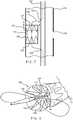
- FIG. 7shows the use of a single length of suture material 138 circumscribing the entirety of the circumference of the secondary stent graft 115. Portions of the suture material 138 located on the outside of the secondary stent graft 115 are shown as a dashed line, while portions of suture material 138 on the inside of the secondary stent graft 115 are shown as a thicker solid line.
- suture material 138is located on the inside of the secondary stent graft 115 only between the struts 140 of the proximal sealing stent 137, and towards the apices 141 thereof.
- the struts 140act to hide or shield the loops 142 of suture material 138 from any later used medical device.
- the suture threads 138are thus somewhat protected by the struts 140 of the proximal sealing stent 137 from snagging on a later inserted medical device.
- a similar arrangementmay also be provided at the proximal end of the proximal sealing stent 137 to restrain this to the auxiliary catheter 148.
- FIG. 8discloses an example of the primary stent graft 114 where the secondary stent graft 115 is in the expanded position.
- the secondary stent graft 115engages against the interior wall of the endoluminal prosthesis to effectively seal the access port 136.
- the secondary stent graft 115is completely concentric with the primary stent graft 114.
- the sealing of the access port 136precludes access to the internal artery and prevents the possibility of leaks into the prosthesis.
- the secondary stent graft 115 in the expanded positionhas an expanded diameter that is less than the expanded diameter of the primary stent graft 114 in the expanded position.
- the secondary stent graft 115 in this examplehas a length that is shorter than the length of the primary stent graft 114.
- the secondary stent graft 115may have a length that is longer that the length of the primary stent graft 114.
- the operatordeploys a guide wire for the introducer 100 into the femoral artery, via an incision and extended up beyond the aortic bifurcation to the aorta.
- the introducer 100is deployed over the guide wire and the introducer 100 is extended up into the aortic bifurcation.
- the sheath 116is withdrawn such that the stent graft 114, including the branch 124, is exposed, but retaining the stent graft 114 at both the proximal and distal ends 121, 122 so that the stent graft 114 is not in a fully expanded configuration.
- the secondary stent graft 115disposed within the interior of the primary stent graft 114 in the compressed position, is retained by trigger wire arrangement 119.
- the trigger wire arrangement 119engages the suture arrangements 138 secured on the proximal 137 and distal ends 139 of the secondary stent graft 115.
- the operatorintroduces a catheter into the stent graft 114 through the access port 136. Through the catheter, the operator can introduce additional endoluminal devices, including, but not limited to, a branch stent graft, into an internal artery through the lumen 125 of the branch 124 of the stent graft 114. The operator may introduce additional endoluminal prostheses into the vessel through the access port 136.
- the secondary stent graft 115 in the compressed positionprovides the operator with access to the access port 136.
- the catheteris removed.
- the operatormay remove the trigger wire arrangement 119 restraining the proximal 137 and distal 139 ends of the secondary stent graft 115.
- the secondary stent graft 115moves from the compressed position to the expanded position.
- the secondary stent graft 115 in the expanded positionis concentric with the primary stent graft 114, and engages the walls to effectively seal the access port 136.
- the operatorthen releases the proximal 121 and distal 122 ends of the primary stent graft 114, and the introducer 100 is removed from the patient.
- FIG. 9provides an alternative example of an endoluminal prosthesis assembly for the treatment of an aortic aneurysm.
- the endoluminal prosthesis assembly 301includes a primary stent graft 314.
- the primary stent graft 314has a main body 323 having a proximal end 321 and a distal end 322 having a bifurcation 345.
- the primary stent graft 314includes a proximally extending suprarenal stent 331 on its proximal end 321.
- the suprarenal stent 331includes barbs 344 configured to engage the wall of the aorta positioned proximal of the renal arteries to secure the primary stent graft 314 when placed within the aorta and to prevent migration within the vessel.
- the primary stent graft 314includes a short leg 346 and a long leg 348 extending from the bifurcation 345 of the stent graft 314.
- the long leg 348has a sealing surface 350 at its distal end 352.
- the long leg 348has a side arm 354 which in this example is in the form of a corrugated tube extending in a partially helical manner from its connection at a fenestration 356 into the long leg 348.
- the side arm 354extends in a distal direction and has a distal end 358 remote from its connection with the long leg 348.
- An access port 336is disposed within the wall of the long leg 348 proximal of the connection of the side arm 354 into the long leg 348.
- an in-dwelling catheter 360extends through the side arm 354 and out through the access port 336.
- the indwelling catheter 360includes a guide wire 362.
- FIG. 10shows the interior of a portion of an example of the long leg 348 of the stent graft 314 while compressed in a delivery device in detail.
- the delivery deviceincludes an introducer catheter 302, which is disposed through the lumen of the long leg 348.
- the long leg 348is substantially tubular having a lumen disposed therethrough.
- the access port 336disposed through the wall of the long leg 348 and provides access to an internal artery, such as the internal iliac artery. Through the access port 336, additional endoluminal devices, including wire guides, sheathes, and catheters, may be deployed into the internal artery without interference.
- the long leg 348also includes a secondary stent graft 315 positioned within its interior opposite of the access port 336.
- the secondary stent graft 315may be secured to the interior wall of the long leg 348 by conventional means including, but not limited to, adhesives and sutures.
- the secondary stent graft 315is in a compressed position.
- the secondary stent graft 315has a proximal end 327 and a distal end 329. Sealing stents 337, 339 are positioned on the proximal 327 and distal ends 329, respectively, of the secondary stent graft 315.
- a trigger wire arrangement 319may include one or more which extend from a trigger wire release mechanism (not shown) of a delivery system for an endoluminal prosthesis.
- the trigger wire arrangement 319is substantially disposed through the introducer catheter 302.
- Two apertures 343are disposed through an introducer catheter 302 to provide access for the trigger wire arrangement 319 to the secondary stent graft 315.
- the trigger wire arrangement 319may also be disposed through an auxiliary catheter (not shown).
- the trigger wire arrangement 319is configured to retain the proximal 337 and distal ends 339 of the secondary stent graft 315 when the secondary stent graft 315 is in the compressed position.
- the proximal 337 and distal ends 339may includes suture arrangements which contain one or more loops configured to engage with the trigger wire arrangement 319 (as described in FIG. 7 ). With the secondary stent graft 315 in the compressed position, an increased amount of working area is provided within the lumen of the longer leg 348 for the deployment of other endoluminal devices through the access port 336. In addition, an operator would have unrestricted access to the internal artery through the access port 336 while the secondary stent graft 315 is restrained the compressed position.
- the trigger wire arrangement 319may be used with a delivery device, such as that described in PCT application WO98/53761 , entitled “A Prosthesis and a Method and Means of Deploying a Prosthesis” used to deploy the endoluminal prosthesis assembly 301.
- PCT application WO98/53761describes a deployment system for an endoluminal prosthesis whereby the prosthesis is radially compressed onto a delivery catheter and is covered by an outer sheath. To deploy the system, the operator slides or retracts the outer sheath over the delivery catheter, thereby exposing the prosthesis. The prosthesis expands outwardly upon removal of the sheath.
- FIG. 11discloses an example of the long leg 348 of the primary stent graft 314 where the secondary stent graft 315 is in the expanded position.
- the secondary stent graft 315engages against the interior wall of the endoluminal prosthesis to effectively seal the access port 336.
- the secondary stent graft 315is completely concentric with the primary stent graft 314.
- the sealing of the access port 336precludes access to the internal artery and prevents the possibility of leaks into the prosthesis.
- the secondary stent graft 315 in the expanded positionhas an expanded diameter that is less than the expanded diameter of the long leg 348 in the expanded position.
- the secondary stent graft 315is this example has a length that is shorter than the length of the long leg 348. In alternative examples, the secondary stent graft 315 may have a length that is longer that the length of the longer leg 348.
- a guide wire for an introducerinto the femoral artery, via an incision and extended up beyond the aortic bifurcation to the aorta.
- the operatordeploys the introducer over the guide wire and positioned within the aorta of a patient.
- the main body 323, the short leg 346 and the long leg 348 of the stent graft 314are deployed, while retaining the superenal stent 331 on the proximal end 321 of the stent graft 314.
- the secondary stent graft 315disposed within the interior of the long leg 348 in the compressed position, is retained by trigger wire arrangement 319.
- the trigger wire arrangement 319engages the suture arrangements secured on the proximal 337 and distal ends 339 of the secondary stent graft 315.
- the operatorintroduces a catheter into the long leg through the side arm 358 and into the lumen of the long leg 348. Through the catheter, the operator can introduce additional endoluminal devices, including, but not limited to, a branch stent graft, into an internal artery through the access port 336.
- the secondary stent graft 315 in the compressed positionprovides the operator with access to the access port 336. Following deployment of the additional endoluminal prosthesis through the access port 336, the catheter is removed.
- the operatormay remove the trigger wire arrangement 319 restraining the proximal 337 and distal 339 ends of the secondary stent graft 315.
- the secondary stent graft 315moves from the compressed position to the expanded position.
- the secondary stent graft 315 in the expanded positionis concentric with the long leg 348, and engages the walls to effectively seal the access port 336.
- the operatorthen releases the suprarenal stent 331 on the proximal end 321 of the primary stent graft 314, and the delivery device is removed from the patient.
Landscapes
- Health & Medical Sciences (AREA)
- Engineering & Computer Science (AREA)
- Biomedical Technology (AREA)
- Heart & Thoracic Surgery (AREA)
- Oral & Maxillofacial Surgery (AREA)
- Transplantation (AREA)
- Cardiology (AREA)
- Vascular Medicine (AREA)
- Life Sciences & Earth Sciences (AREA)
- Animal Behavior & Ethology (AREA)
- General Health & Medical Sciences (AREA)
- Public Health (AREA)
- Veterinary Medicine (AREA)
- Pulmonology (AREA)
- Gastroenterology & Hepatology (AREA)
- Prostheses (AREA)
Description
- This invention relates generally to an endoluminal prosthesis and particularly to a endoluminal prosthesis having a fenestration that is implantable within the human or animal body for the repair of damaged vessels, ducts or other physiological passageways and cavities, and more particularly to systems for facilitating deployment of such an endoluminal prosthesis.
- The physiological passageways and cavities of human and animal bodies, for example, blood vessels and ducts, occasionally weaken or even rupture. One common surgical intervention for weakened, aneurysmal or ruptured passageways or ducts involves the use of an endoluminal prosthesis to provide some or all of the functionality of the original, healthy passageway or duct and/or to preserve any remaining vascular integrity by replacing a length of the existing passageway or duct wall that spans the site of failure or defect. Endoluminal prostheses may be of a unitary construction or may be comprised of multiple prosthetic modules.
- A modular prosthesis allows a surgeon to accommodate a wide variation in vessel morphology while reducing the necessary inventory of differently sized prostheses. For example, aortas vary in length, diameter and angulation between the renal artery region and the region of the aortic bifurcation. Prosthetic modules that fit each of these variables can be assembled to form a prosthesis, obviating the need for a custom prosthesis or large inventories of prostheses that accommodate all possible combinations of these variables. A modular system may also accommodate deployment options by allowing the proper placement of one module before the implantation of an adjoining module.
- Generally, when deploying an endovascular prosthesis into a body lumen, it is possible to obtain access to such a body lumen from each end of the lumen where necessary, thereby facilitating placement of a device in the lumen. There can be problems, however, if the aneurysm of the aorta extends down into one or other of the iliac arteries. Each of the common iliac arteries branches into the internal and external iliac arteries and it is necessary in such a situation that a blood flow path can be directed through an endovascular stent graft into each of these arteries. The internal iliac artery which extends from the common iliac artery below the aortic bifurcation is for all intents and purposes a blind vessel because there is no practical way of performing an endovascular minimally invasive procedure into that vessel other than by entry from the common iliac artery.
WO 2007/124053 describes a bifurcated stent graft in which one of the legs can include a valved aperture.US 2005/0059923 describes a covered stent having a fenestration in its side wall that can be selectively closed.- Aspects of the present invention are defined in the claims.
- Described is an endoluminal prosthesis assembly for placement in a diseased vessel. The endoluminal prosthesis assembly comprises a first stent graft having a first end and a second end and an interior lumen. The first stent graft has an expanded position and a compressed position and defines an access port disposed through a wall of the first stent graft between the first and second ends of the first stent graft. The endoluminal prosthesis assembly further comprises a second stent graft being disposed within the interior lumen of the first stent graft. The second stent graft may be disposed entirely within the interior lumen of the first stent graft. The second stent graft is disposed within the first stent graft and has an expanded position and a
compressed position, where the second stent graft is compressed against an interior wall of the first stent graft opposite the access port. In the compressed position, the second stent graft contacts only a portion of an interior wall of the first stent graft and the access port is in fluid communication with the interior lumen of the first stent graft. In the compressed position, the second stent graft
may contact only a portion of a circumference of the interior wall of the first stent graft. In the expanded position, the second stent graft engages substantially all of a circumference of the interior wall of the first stent graft and seals the access port from fluid communication with the interior lumen of the first stent graft. In the expanded position, the second stent graft may engage substantially all of the interior wall of the first stent graft. - In one aspect, the second stent graft is secured to the interior wall of the first stent graft. In another aspect, the second stent graft is restrained in the compressed position by a trigger wire arrangement. The trigger wire arrangement may engage the first end of the second stent graft and the second end of the stent graft. The trigger wire arrangement may engage a first suture arrangement on the first end of the second stent graft. The trigger wire arrangement may engage a second suture arrangement of the second end of the second graft.
- In another example, the second stent graft is concentric with the first stent graft and has a diameter that is less than the first stent graft when in the expanded position. In another aspect, the length of the second stent graft is shorter than the length of the first stent graft. The length of the second stent graft may be longer than the length of the first stent graft, or the same as the length of the first stent graft.
- With the secondary stent graft in the compressed position, the first and second ends of the second stent graft may be restrained and the access port is in fluid communication with the lumen of the primary stent graft, which allows for the deployment of other endoluminal devices through the access port.
- In another aspect, a delivery system for an endoluminal prosthesis comprises an introducer that includes a distal end intended to remain outside a patient in use and a proximal end. The proximal end of the introducer has a nose cone dilator and a retention arrangement distal of the nose cone dilator. An endoluminal prosthesis assembly is retained on the introducer. The endoluminal prosthesis assembly comprises a first stent graft having a first end and a second end and an interior lumen. The first stent graft has an expanded position and a compressed position and defines an access port disposed through a wall of the first stent graft between the first and second ends of the first stent graft. The endoluminal prosthesis assembly further comprises a second stent graft being disposed entirely within the interior lumen of the first stent graft. The second stent graft is disposed within the first stent graft and has an expanded position and a compressed position, where the second stent graft is compressed against an interior wall of the first stent graft opposite the access port. The delivery system further includes a trigger wire arrangement engaging a suture arrangement secured to the first end and a suture arrangement secured to the second end of the second stent graft to retain the second stent graft in the compressed position. In one embodiment, the suture arrangement includes a single length of suture material. In another embodiment, the delivery system includes a second suture arrangement secured to the second end of the second stent graft and is engaged with the trigger wire arrangement. In another embodiment, the suture arrangements include a plurality of loops that engage the trigger wire arrangement.
- Other systems, features and advantages of the invention will be, or will become, apparent to one with skill in the art upon examination of the following figures and detailed description. It is intended that all such additional systems, features and advantages be within the scope of the invention, and be encompassed by the following claims.
- Embodiments of the present invention are described below, by way of example only, with reference to the accompanying drawings, in which:
FIG. 1 shows a schematic view of a deployment device for an example of an endoluminal prosthesis assembly.FIG. 2 shows a retention apparatus for retaining the proximal end of the endoluminal prosthesis assembly ofFIG. 1 .FIG. 3 shows a retention apparatus for retaining the distal end of the endoluminal prosthesis assembly ofFIG. 1 .FIG. 4 shows a schematic view of the exterior of the endoluminal prosthesis assembly ofFIG. 1 .FIG. 5 shows a schematic view of the interior of the endoluminal prosthesis assembly ofFIG. 1 , where a secondary stent graft is in a compressed position.FIG. 6 shows a cross-sectional view of the proximal end of the secondary stent graft of the endoluminal prosthesis assembly ofFIG. 1 .FIG. 7 shows a suture arrangement used for retention of the proximal end of a secondary stent graft of the endoluminal prosthesis assembly ofFIG. 1 .FIG. 8 shows the cross-sectional view of the secondary stent graft of the endoluminal prosthesis assembly ofFIG. 1 , where the secondary stent graft is in an expanded position.FIG. 9 shows a schematic view of an alternative example of an endoluminal prosthesis assembly.FIG. 10 shows a schematic view of the interior of the endoluminal prosthesis assembly ofFIG. 9 , where a secondary stent graft is in a compressed position.FIG. 11 shows a cross-sectional view of the secondary stent graft of the endoluminal prosthesis assembly ofFIG. 9 , where a secondary stent graft is in an expanded position.- The components in the drawings are not necessarily to scale, emphasis instead being upon illustrating the principles of the teachings herein.
- Unless defined otherwise, all technical and scientific terms used herein have the same meaning as commonly understood by one of ordinary skill in the art to which this invention pertains.
- The term "prosthesis" means any device for insertion or implantation into, or replacement, for a body part or function of that body part. It may also mean a device that enhances or adds functionality to a physiological system. The term prosthesis may include, for example and without limitation, a stent, stent-graft, filter, valve, balloon, embolization coil, and the like.
- The term "endoluminal" refers to or describes the internal or inside of a lumen, duct, and other passageways or cavities located in a human or other animal body. A lumen or a body passageway may be an existing lumen or a lumen created by surgical intervention. As used in this specification, the terms "lumen" or "body passageway," and "vessel" are intended to have a broad meaning and encompass any duct (e.g., natural or iatrogenic) or cavity within the human body and may include, without limitation, blood vessels, respiratory ducts, gastrointestinal ducts, such as the biliary duct, intestines, the esophagus, the pericardial cavity, the thoracic cavity, and the like. Accordingly, the terms "endoluminal device" or "endoluminal prosthesis" describe devices that can be placed inside or moved through any such lumen or duct.
- The term "graft" or "graft material" describes an object, device, or structure that is joined to or that is capable of being joined to or implanted in or against a body part to enhance, repair, or replace a portion or a function of that body part. A graft by itself or with the addition of other elements, such as structural components, may constitute an endoluminal prosthesis. The graft may be comprised of a single material, a blend of materials, a weave, a laminate, or a composite of two or more materials. The graft may also be constructed from a synthetic, for example and without limitation, a polymer. The graft may be formed from a single layer or multiple layers of material. In examples employing a plurality of layers of material, the layers may remain separate, or may be attached to each other through a secondary process such as sintering, curing, adhesives, and sutures or the like.
- The terms "patient," "subject," and "recipient" as used in this application may refer to any animal, particularly humans.
- The terms "proximal" and "distal" will be used to describe opposing axial ends of the delivery system, as well as the axial ends of various component features. The term "proximal" is used to refer to the end of the system (or component thereof) that is initially inserted into the patient, or that is closest to the patient during use. The term "distal" is used to refer to the end of the system (or component thereof) that is closest to the operator during use of the system.
- The term "biocompatible" refers to a material that is substantially non-toxic in the in vivo environment of its intended use, and that is not substantially rejected by the patient's physiological system (i.e., is non-antigenic). This can be gauged by the ability of a material to pass the biocompatibility tests set forth in International Standards Organization (ISO) Standard No. 10993 and/or the U.S. Pharmacopeia (USP) 23 and/or the U.S. Food and Drug Administration (FDA) blue book memorandum No. G95-1, entitled "Use of International Standard ISO-10993, Biological Evaluation of Medical Devices Part-1: Evaluation and Testing." Typically, these tests measure a material's toxicity, infectivity, pyrogenicity, irritation potential, reactivity, hemolytic activity, carcinogenicity and/or immunogenicity. A biocompatible structure or material, when introduced into a majority of patients, will not cause a significantly adverse, long-lived or escalating biological reaction or response, and is distinguished from a mild, transient inflammation which typically accompanies surgery or implantation of foreign objects into a living organism.
- Now first looking at
FIG. 1 , anintroducer 100 for an example of anendoluminal prosthesis 101 mounted onto theintroducer 100 is shown schematically. Theintroducer 100 has anintroducer catheter 102 extending over aguide wire catheter 104. Theguide wire catheter 104 extends from thedistal end 108 of theintroducer 100 to immediately distal of thenose cone dilator 112, which is at theproximal end 110 of theintroducer 100. Asheath 116 operated by asheath manipulator 117 is mounted on theintroducer catheter 102. Thesheath 116, as illustrated, is withdrawn so that theendoluminal prosthesis 101 is in an expanded position to show detail of theprosthesis 101. Thesheath 116 is configured to extend over theendoluminal prosthesis 101 to thenose cone dilator 112 and keeps theendoluminal prosthesis 101 in a compressed configuration prior to deployment within the target vessel. Theendoluminal prosthesis 101 is retained at itsproximal end 121 by a proximal retention arrangement positioned immediately distal of thenose cone dilator 112.FIG. 2 discloses one method of proximal retention of theendoluminal prosthesis assembly 101. Theendoluminal device 101 may be positioned immediately distal of thenose cone dilator 112. As shown, the proximal retention arrangement may compriseloops 202 of fiber or suture material engaged with atrigger wire 204 extending from an aperture in theguide wire catheter 104 distal to thenose cone dilator 112. Theloops 202 are placed so that there is formed a smaller 206 and larger 208 fold of theendoluminal prosthesis assembly 101 at its proximal end. FIG. 3 discloses one method of distal retention of theendoluminal prosthesis assembly 101. As shown, thedistal end 122 of theendoluminal prosthesis 101 is retained on theguide wire catheter 104 just proximal of the proximal end of theintroducer catheter 102 by means of a loop oftrigger wire 212 extending from theintroducer catheter 102. Removal of thetrigger wire 212 will release thedistal end 122 of theendoluminal prosthesis 101.- Referring back to
FIG. 1 , ahandle 118 at the distal end of theintroducer catheter 102 enables manipulation of theintroducer 100. Anindwelling catheter 120 enters a lumen (not shown) of theintroducer catheter 102 at thehandle 118 and exits from theintroducer catheter 102 at thedistal end 122 of theendoluminal prosthesis 101. Within theindwelling catheter 120, there is aguide wire 128. Thisguide wire 128 can be pushed through theindwelling catheter 120 so that it extends beyond thetip 130 of thenose cone dilator 112. Preferably, the proximal end of theindwelling catheter 120 is tapered to closely fit around theguide wire 128 to prevent blood loss through theindwelling catheter 120. Theindwelling catheter 120 enters the lumen of thebranch 124 through itsdistal end 125 and exits theendoluminal prosthesis assembly 101 adjacent to thenose cone dilator 112 and extends along the side of thenose cone dilator 112 in agroove 126 formed in thenose cone dilator 112. Theendoluminal prosthesis 101 further includes anaccess port 136. FIGS. 4 and5 provide a more detailed view of the fenestratedendovascular device assembly 101. Referring toFIG. 4 , the fenestratedendovascular device assembly 101 includes astent graft 114 having a substantially tubularmain body 123 with a main lumen disposed therethrough and a side lumen through abranch 124. Sealingstents distal ends 122, respectively, of themain body 123 of thestent graft 114. A sealingstent 135 is positioned on thedistal end 125 of thebranch 124 of thestent graft 114. Theintroducer catheter 102 is disposed through the main lumen of thestent graft 114.- The
stents stents stents FIG. 4 , it will be appreciated that the exact number of stents, and their location, may be varied. - In one example, shown in
FIG. 4 ., thestents stents - The
primary stent graft 114 includes anaccess port 136, or fenestration, disposed through the wall of themain body 123 and provides access to an internal artery, such as the internal iliac artery. Through theaccess port 136, additional endoluminal devices, including wire guides, sheathes, and catheters, may be deployed into the internal artery. Theprimary stent graft 114 also includes asecondary stent graft 115 disposed within its lumen. Thesecondary stent graft 115 is retained by atrigger wire arrangement 119. Thesecondary stent graft 115 may be secured to the wall of theprimary stent graft 114 by conventional means including, but not limited to, adhesives and sutures. - The
primary stent graft 114 and thesecondary stent graft 115 may be constructed from a biocompatible material. Examples of biocompatible materials from which textile graft material can be formed include, without limitation, polyesters, such as polyethylene terephthalate; fluorinated polymers, such as polytetrafluoroethylene (PTFE) and fibers of expanded PTFE, and polyurethanes. For example, theprimary stent graft 114 and thesecondary stent graft 115 may be constructed from woven multifilament polyester, for example and without limitation, Dacron™, produced by DuPont. Dacron™ is known to be sufficiently biologically inert, non-biodegradable, and durable to permit safe insertion inside the human body. FIG. 5 shows an interior view of an example of theprimary stent graft 114.- As shown, the
secondary stent graft 115 is in a compressed position. Thesecondary stent graft 115 has aproximal end 127 and adistal end 129. Sealingstents distal ends 129, respectively, of thesecondary stent graft 115. Thesecondary stent graft 115 is compressed against a portion of the interior wall of theprimary stent graft 114 opposite of theaccess port 136. In alternative examples, thesecondary stent graft 115 may be placed in other positions within the lumen of theprimary stent graft 114. Thetrigger wire arrangement 119 may include one or more wires which extend from a trigger wire release mechanism (not shown) to the proximal end ofintroducer 100 distal to thenose cone dilator 112. Thetrigger wire arrangement 119 is substantially disposed through theintroducer catheter 102 and extends from a handle at the distal end of theintroducer 100. Thetrigger wire arrangement 119 may also be disposed through an auxiliary catheter (as described inFIG. 6 ). Twoapertures 143 are disposed through theintroducer catheter 102 to provide access to thesecondary stent graft 115. Thetrigger wire arrangement 119 is configured to restrain the proximal 137 anddistal ends 139 of thesecondary stent graft 115 when thesecondary stent graft 115 is in the compressed position. With thesecondary stent graft 115 in the compressed position, theaccess port 136 is in fluid communication with the lumen of theprimary stent graft 114, which allows for the deployment of other endoluminal devices through theaccess port 136. In addition, thesecondary stent graft 114 in the compressed position provides unrestricted access to the internal artery through theaccess port 136 while thesecondary stent graft 115 is restrained the compressed position. - An example of the
proximal end 127 of thesecondary stent graft 115 is shown in greater detail inFIG. 6 . As shown, theproximal end 137 of thesecondary stent graft 115 may be restrained by thetrigger wire arrangement 119 engaging afirst suture arrangement 138. Thefirst suture arrangement 138 includes one ormore loops 142 that may be pulled into the center of thesecondary stent graft 115 towards anauxiliary catheter 148 and held thereto by atrigger wire arrangement 119 within the lumen of theauxiliary catheter 148 through a plurality ofopenings 144. A plurality ofstruts 140 of the proximal sealingstent 137 are restrained by eachloop 142 of thesuture arrangement 138 positioned betweenbends 141 of thestent 137, thereby pulling the entirety of theproximal end 137 of the stent towardsauxiliary catheter 148. Theproximal sealing stent 137 may be restrained in such a way that the entirety of the distal end of the proximal sealingstent 137 is pulled inwardly to some extent and thus lies within the circumference of the lumen of thesecondary stent graft 115 and holds thesecondary stent graft 115 to theauxiliary catheter 148 during deployment. Thedistal sealing stent 139 of thesecondary stent graft 115 can be restrained by a comparable second suture arrangement. In alternative examples, theproximal end 137 anddistal end 139 may be restrained through the use of other procedures and techniques. - A variety of different examples of
suture arrangements 138 for thesecondary stent graft 115 are possible. One example is shown inFIG. 7. FIG. 7 shows the use of a single length ofsuture material 138 circumscribing the entirety of the circumference of thesecondary stent graft 115. Portions of thesuture material 138 located on the outside of thesecondary stent graft 115 are shown as a dashed line, while portions ofsuture material 138 on the inside of thesecondary stent graft 115 are shown as a thicker solid line. It can be seen thatsuture material 138 is located on the inside of thesecondary stent graft 115 only between thestruts 140 of the proximal sealingstent 137, and towards theapices 141 thereof. In this way, thestruts 140 act to hide or shield theloops 142 ofsuture material 138 from any later used medical device. Thesuture threads 138 are thus somewhat protected by thestruts 140 of the proximal sealingstent 137 from snagging on a later inserted medical device. A similar arrangement may also be provided at the proximal end of the proximal sealingstent 137 to restrain this to theauxiliary catheter 148. - The skilled person will appreciate that there are many modifications that could be made to the restraining apparatus of this example.
U.S. Patent Application Ser. No. 12/609,066 entitled "Introducer for Deploying a Stent Graft in a Curved Lumen and Stent Graft Therefor," which is published asUS 2010/0114291 , discloses arrangements for restraining the ends of an endoluminal device. FIG. 8 discloses an example of theprimary stent graft 114 where thesecondary stent graft 115 is in the expanded position. In the expanded position, thesecondary stent graft 115 engages against the interior wall of the endoluminal prosthesis to effectively seal theaccess port 136. Thesecondary stent graft 115 is completely concentric with theprimary stent graft 114. The sealing of theaccess port 136 precludes access to the internal artery and prevents the possibility of leaks into the prosthesis. Thesecondary stent graft 115 in the expanded position has an expanded diameter that is less than the expanded diameter of theprimary stent graft 114 in the expanded position. Thesecondary stent graft 115 in this example has a length that is shorter than the length of theprimary stent graft 114. In alternative examples, thesecondary stent graft 115 may have a length that is longer that the length of theprimary stent graft 114.- In use, the operator deploys a guide wire for the
introducer 100 into the femoral artery, via an incision and extended up beyond the aortic bifurcation to the aorta. Theintroducer 100 is deployed over the guide wire and theintroducer 100 is extended up into the aortic bifurcation. Thesheath 116 is withdrawn such that thestent graft 114, including thebranch 124, is exposed, but retaining thestent graft 114 at both the proximal anddistal ends stent graft 114 is not in a fully expanded configuration. Thesecondary stent graft 115, disposed within the interior of theprimary stent graft 114 in the compressed position, is retained bytrigger wire arrangement 119. Thetrigger wire arrangement 119 engages thesuture arrangements 138 secured on the proximal 137 anddistal ends 139 of thesecondary stent graft 115. The operator introduces a catheter into thestent graft 114 through theaccess port 136. Through the catheter, the operator can introduce additional endoluminal devices, including, but not limited to, a branch stent graft, into an internal artery through thelumen 125 of thebranch 124 of thestent graft 114. The operator may introduce additional endoluminal prostheses into the vessel through theaccess port 136.U.S. Patent Application Ser. No. 10/962,763 entitled "Introducer for an Iliac Side Branch Device," which is published asUS 2005/0182476 , discloses an arrangement for using an indwelling catheter to access an internal iliac artery. Thesecondary stent graft 115 in the compressed position provides the operator with access to theaccess port 136. Following deployment of the additional endoluminal prostheses through theaccess port 136, the catheter is removed. The operator may remove thetrigger wire arrangement 119 restraining the proximal 137 and distal 139 ends of thesecondary stent graft 115. Thesecondary stent graft 115 moves from the compressed position to the expanded position. Thesecondary stent graft 115 in the expanded position is concentric with theprimary stent graft 114, and engages the walls to effectively seal theaccess port 136. The operator then releases the proximal 121 and distal 122 ends of theprimary stent graft 114, and theintroducer 100 is removed from the patient. FIG. 9 provides an alternative example of an endoluminal prosthesis assembly for the treatment of an aortic aneurysm. In this example, theendoluminal prosthesis assembly 301 includes aprimary stent graft 314. Theprimary stent graft 314 has amain body 323 having aproximal end 321 and adistal end 322 having abifurcation 345. Theprimary stent graft 314 includes a proximally extendingsuprarenal stent 331 on itsproximal end 321. Thesuprarenal stent 331 includesbarbs 344 configured to engage the wall of the aorta positioned proximal of the renal arteries to secure theprimary stent graft 314 when placed within the aorta and to prevent migration within the vessel. Theprimary stent graft 314 includes ashort leg 346 and along leg 348 extending from thebifurcation 345 of thestent graft 314. Thelong leg 348 has a sealingsurface 350 at itsdistal end 352. Thelong leg 348 has aside arm 354 which in this example is in the form of a corrugated tube extending in a partially helical manner from its connection at afenestration 356 into thelong leg 348. Theside arm 354 extends in a distal direction and has adistal end 358 remote from its connection with thelong leg 348. Anaccess port 336 is disposed within the wall of thelong leg 348 proximal of the connection of theside arm 354 into thelong leg 348. During deployment of thestent graft 314 into the vasculature of a patient, an in-dwellingcatheter 360 extends through theside arm 354 and out through theaccess port 336. Theindwelling catheter 360 includes aguide wire 362.FIG. 10 shows the interior of a portion of an example of thelong leg 348 of thestent graft 314 while compressed in a delivery device in detail. The delivery device includes anintroducer catheter 302, which is disposed through the lumen of thelong leg 348. Thelong leg 348 is substantially tubular having a lumen disposed therethrough. Theaccess port 336 disposed through the wall of thelong leg 348 and provides access to an internal artery, such as the internal iliac artery. Through theaccess port 336, additional endoluminal devices, including wire guides, sheathes, and catheters, may be deployed into the internal artery without interference. Thelong leg 348 also includes asecondary stent graft 315 positioned within its interior opposite of theaccess port 336. Thesecondary stent graft 315 may be secured to the interior wall of thelong leg 348 by conventional means including, but not limited to, adhesives and sutures.- As shown, the
secondary stent graft 315 is in a compressed position. Thesecondary stent graft 315 has aproximal end 327 and adistal end 329. Sealingstents distal ends 329, respectively, of thesecondary stent graft 315. Atrigger wire arrangement 319 may include one or more which extend from a trigger wire release mechanism (not shown) of a delivery system for an endoluminal prosthesis. Thetrigger wire arrangement 319 is substantially disposed through theintroducer catheter 302. Twoapertures 343 are disposed through anintroducer catheter 302 to provide access for thetrigger wire arrangement 319 to thesecondary stent graft 315. Thetrigger wire arrangement 319 may also be disposed through an auxiliary catheter (not shown). Thetrigger wire arrangement 319 is configured to retain the proximal 337 anddistal ends 339 of thesecondary stent graft 315 when thesecondary stent graft 315 is in the compressed position. The proximal 337 anddistal ends 339 may includes suture arrangements which contain one or more loops configured to engage with the trigger wire arrangement 319 (as described inFIG. 7 ). With thesecondary stent graft 315 in the compressed position, an increased amount of working area is provided within the lumen of thelonger leg 348 for the deployment of other endoluminal devices through theaccess port 336. In addition, an operator would have unrestricted access to the internal artery through theaccess port 336 while thesecondary stent graft 315 is restrained the compressed position. - The
trigger wire arrangement 319 may be used with a delivery device, such as that described inPCT application WO98/53761 endoluminal prosthesis assembly 301.PCT application WO98/53761 FIG. 11 discloses an example of thelong leg 348 of theprimary stent graft 314 where thesecondary stent graft 315 is in the expanded position. In the expanded position, thesecondary stent graft 315 engages against the interior wall of the endoluminal prosthesis to effectively seal theaccess port 336. Thesecondary stent graft 315 is completely concentric with theprimary stent graft 314. The sealing of theaccess port 336 precludes access to the internal artery and prevents the possibility of leaks into the prosthesis. Thesecondary stent graft 315 in the expanded position has an expanded diameter that is less than the expanded diameter of thelong leg 348 in the expanded position. Thesecondary stent graft 315 is this example has a length that is shorter than the length of thelong leg 348. In alternative examples, thesecondary stent graft 315 may have a length that is longer that the length of thelonger leg 348.- In use, a guide wire for an introducer into the femoral artery, via an incision and extended up beyond the aortic bifurcation to the aorta. The operator deploys the introducer over the guide wire and positioned within the aorta of a patient. The
main body 323, theshort leg 346 and thelong leg 348 of thestent graft 314 are deployed, while retaining thesuperenal stent 331 on theproximal end 321 of thestent graft 314. Thesecondary stent graft 315, disposed within the interior of thelong leg 348 in the compressed position, is retained bytrigger wire arrangement 319. Thetrigger wire arrangement 319 engages the suture arrangements secured on the proximal 337 anddistal ends 339 of thesecondary stent graft 315. The operator introduces a catheter into the long leg through theside arm 358 and into the lumen of thelong leg 348. Through the catheter, the operator can introduce additional endoluminal devices, including, but not limited to, a branch stent graft, into an internal artery through theaccess port 336. Thesecondary stent graft 315 in the compressed position provides the operator with access to theaccess port 336. Following deployment of the additional endoluminal prosthesis through theaccess port 336, the catheter is removed. The operator may remove thetrigger wire arrangement 319 restraining the proximal 337 and distal 339 ends of thesecondary stent graft 315. Thesecondary stent graft 315 moves from the compressed position to the expanded position. Thesecondary stent graft 315 in the expanded position is concentric with thelong leg 348, and engages the walls to effectively seal theaccess port 336. The operator then releases thesuprarenal stent 331 on theproximal end 321 of theprimary stent graft 314, and the delivery device is removed from the patient. - Throughout this specification various indications have been given as to preferred and alternative embodiments of the invention. However, the foregoing detailed description is to be regarded as illustrative rather than limiting and the invention is not limited to any one of the provided embodiments. It should be understood that it is the appended claims that are intended to define the scope of this invention.
Claims (10)
- A delivery system for an endoluminal prosthesis (101), comprising:an introducer (100), the introducer having a distal end intended to remain outside a patient in use and a proximal end,a carrier (102) for an endoluminal prosthesis assembly disposed within the introducer, the endoluminal prosthesis assembly comprising,a first stent graft (114) having a first end (121) and a second end (122) and an interior lumen, the first stent graft having an expanded position and a compressed position, the first stent graft defining an access port (136) disposed through a wall of the first stent graft between the first and second ends of the first stent graft; anda second stent graft (115) having a first end (127) and a second end (129), the second stent graft being disposed within the first stent graft, the second stent graft having an expanded position and a compressed position where the second stent graft is compressed against an interior wall of the first stent graft opposite the access port (136); where in the compressed position, the second stent graft (115) contacts only a portion of a circumference of the interior wall of the first stent graft(114) such that the access port (136) is in fluid communication with the interior lumen of the first stent graft (114), and in the expanded position, the second stent graft (115) engages substantially all of a circumference of the interior wall of the first stent graft (114) so as to seal the access port (136) from fluid communication with the interior lumen of the first stent graft (114);a trigger wire arrangement (119) engaging a first end (127) and a second end (129) of the second stent graft to restrain the second stent graft (115) in the compressed position, wherein the trigger wire arrangement (119) is removable to enable the secondary stent graft (115) to move from the compressed position to the expanded position.
- The delivery system of claim 1, where the trigger wire arrangement (119) comprises one or more wires
- The delivery system of any of claims 1 and 2, where the first end and the second end of the stent graft include suture arrangements (138).
- The delivery system of claim 3, where the suture arrangements (138) include a plurality of loops (142) to engage the trigger wire arrangement (119).
- The delivery system of any of claims 1 to 4, where the trigger wire arrangement (119) is substantially disposed through an auxiliary catheter.
- The delivery system for an endoluminal prosthesis of claim 1, where a portion of the second stent graft (115) is secured to the interior wall of the first stent graft (114).
- The delivery system for an endoluminal prosthesis of any preceding claim, where the length of the second stent graft (115) is at least one of: shorter than the length of the first stent graft (114); longer than the length of the first stent graft; and the same length as the first stent graft.
- The delivery system for an endoluminal prosthesis claim 1, where the trigger wire arrangement (119) engages at least one of:
a first suture arrangement (138) on the first end of the second stent graft; and a second suture arrangement of the second end (129) of the second stent graft. - The endoluminal prosthesis assembly of any preceding claim, where the second stent graft (115) is concentric with the first stent graft (114) and has a diameter in the expanded position that is less than the first stent graft in the expanded position.
- The delivery system for an endoluminal prosthesis of claim 1, where in the compressed position, the access port (136) is in fluid communication with the interior lumen of the first stent graft (114), and in the expanded position, the second stent graft (115) engages substantially all of a circumference of the interior wall of the first stent graft (114) so as to seal the access port (136) from fluid communication with the interior lumen of the first stent graft (114).
Applications Claiming Priority (1)
| Application Number | Priority Date | Filing Date | Title |
|---|---|---|---|
| US201161529597P | 2011-08-31 | 2011-08-31 |
Publications (2)
| Publication Number | Publication Date |
|---|---|
| EP2564812A1 EP2564812A1 (en) | 2013-03-06 |
| EP2564812B1true EP2564812B1 (en) | 2018-12-19 |
Family
ID=46796488
Family Applications (1)
| Application Number | Title | Priority Date | Filing Date |
|---|---|---|---|
| EP12275127.4AActiveEP2564812B1 (en) | 2011-08-31 | 2012-08-29 | Delivery system for an endoluminal prosthesis |
Country Status (2)
| Country | Link |
|---|---|
| US (1) | US11185403B2 (en) |
| EP (1) | EP2564812B1 (en) |
Cited By (15)
| Publication number | Priority date | Publication date | Assignee | Title |
|---|---|---|---|---|
| US10856984B2 (en) | 2017-08-25 | 2020-12-08 | Neovasc Tiara Inc. | Sequentially deployed transcatheter mitral valve prosthesis |
| US10940001B2 (en) | 2012-05-30 | 2021-03-09 | Neovasc Tiara Inc. | Methods and apparatus for loading a prosthesis onto a delivery system |
| US11311376B2 (en) | 2019-06-20 | 2022-04-26 | Neovase Tiara Inc. | Low profile prosthetic mitral valve |
| US11357622B2 (en) | 2016-01-29 | 2022-06-14 | Neovase Tiara Inc. | Prosthetic valve for avoiding obstruction of outflow |
| US11389291B2 (en) | 2013-04-04 | 2022-07-19 | Neovase Tiara Inc. | Methods and apparatus for delivering a prosthetic valve to a beating heart |
| US11413139B2 (en) | 2011-11-23 | 2022-08-16 | Neovasc Tiara Inc. | Sequentially deployed transcatheter mitral valve prosthesis |
| US11419720B2 (en) | 2010-05-05 | 2022-08-23 | Neovasc Tiara Inc. | Transcatheter mitral valve prosthesis |
| US11464631B2 (en) | 2016-11-21 | 2022-10-11 | Neovasc Tiara Inc. | Methods and systems for rapid retraction of a transcatheter heart valve delivery system |
| US11491006B2 (en) | 2019-04-10 | 2022-11-08 | Neovasc Tiara Inc. | Prosthetic valve with natural blood flow |
| US11497602B2 (en) | 2012-02-14 | 2022-11-15 | Neovasc Tiara Inc. | Methods and apparatus for engaging a valve prosthesis with tissue |
| US11602429B2 (en) | 2019-04-01 | 2023-03-14 | Neovasc Tiara Inc. | Controllably deployable prosthetic valve |
| US11737872B2 (en) | 2018-11-08 | 2023-08-29 | Neovasc Tiara Inc. | Ventricular deployment of a transcatheter mitral valve prosthesis |
| US11779742B2 (en) | 2019-05-20 | 2023-10-10 | Neovasc Tiara Inc. | Introducer with hemostasis mechanism |
| US11998447B2 (en) | 2019-03-08 | 2024-06-04 | Neovasc Tiara Inc. | Retrievable prosthesis delivery system |
| US12109111B2 (en) | 2015-12-15 | 2024-10-08 | Neovasc Tiara Inc. | Transseptal delivery system |
Families Citing this family (9)
| Publication number | Priority date | Publication date | Assignee | Title |
|---|---|---|---|---|
| US10028747B2 (en) | 2008-05-01 | 2018-07-24 | Aneuclose Llc | Coils with a series of proximally-and-distally-connected loops for occluding a cerebral aneurysm |
| US10716573B2 (en) | 2008-05-01 | 2020-07-21 | Aneuclose | Janjua aneurysm net with a resilient neck-bridging portion for occluding a cerebral aneurysm |
| US9358140B1 (en) | 2009-11-18 | 2016-06-07 | Aneuclose Llc | Stent with outer member to embolize an aneurysm |
| US9693860B2 (en) | 2014-12-01 | 2017-07-04 | Medtronic, Inc. | Segmented transcatheter valve prosthesis having an unsupported valve segment |
| WO2018045097A1 (en)* | 2016-08-31 | 2018-03-08 | Endologix, Inc. | Systems and methods with stent and filling structure |
| US10500079B2 (en) | 2016-10-27 | 2019-12-10 | Cook Medical Technologies Llc | Preloaded branch wire loop constraint |
| WO2018157177A1 (en)* | 2017-02-27 | 2018-08-30 | Thuy Pham | Novel transcatheter valve replacement device |
| JP7569219B2 (en) | 2018-05-31 | 2024-10-17 | エンドロジックス リミテッド ライアビリティ カンパニー | STENT GRAFT SYSTEM HAVING CONSTRAINTS IN A CHANNEL AND METHOD THEREOF - Patent application |
| US11357612B2 (en) | 2020-07-16 | 2022-06-14 | Medtronic Vascular, Inc. | Stent graft with sacrificial port |
Family Cites Families (20)
| Publication number | Priority date | Publication date | Assignee | Title |
|---|---|---|---|---|
| US5366473A (en) | 1992-08-18 | 1994-11-22 | Ultrasonic Sensing And Monitoring Systems, Inc. | Method and apparatus for applying vascular grafts |
| US5667523A (en) | 1995-04-28 | 1997-09-16 | Impra, Inc. | Dual supported intraluminal graft |
| DE19720115C2 (en) | 1997-05-14 | 1999-05-20 | Jomed Implantate Gmbh | Stent graft |
| AUPO700897A0 (en) | 1997-05-26 | 1997-06-19 | William A Cook Australia Pty Ltd | A method and means of deploying a graft |
| US6102918A (en) | 1998-02-18 | 2000-08-15 | Montefiore Hospital And Medical Center | Collapsible low-profile vascular graft implantation instrument and method for use thereof |
| US6280467B1 (en) | 1998-02-26 | 2001-08-28 | World Medical Manufacturing Corporation | Delivery system for deployment and endovascular assembly of a multi-stage stented graft |
| DK1263349T3 (en) | 2000-03-14 | 2009-10-19 | Cook Inc | Endovascular stent graft |
| AU2001259488A1 (en) | 2000-05-05 | 2001-11-20 | The Board Of Trustees Of The Leland Standford Junior University | Multilayer stents having enhanced flexibility and hoop strength |
| US6613078B1 (en) | 2000-08-02 | 2003-09-02 | Hector Daniel Barone | Multi-component endoluminal graft assembly, use thereof and method of implanting |
| US20040215322A1 (en) | 2001-07-06 | 2004-10-28 | Andrew Kerr | Stent/graft assembly |
| US6752825B2 (en) | 2001-10-02 | 2004-06-22 | Scimed Life Systems, Inc | Nested stent apparatus |
| US20040186551A1 (en) | 2003-01-17 | 2004-09-23 | Xtent, Inc. | Multiple independent nested stent structures and methods for their preparation and deployment |
| US20050059923A1 (en)* | 2003-09-17 | 2005-03-17 | Ricardo Gamboa | Fenestration with intrinsic means of selective closure incorporated to a tubular body and used in interventional cardiovascular procedures |
| US20050113904A1 (en) | 2003-11-25 | 2005-05-26 | Shank Peter J. | Composite stent with inner and outer stent elements and method of using the same |
| US7530994B2 (en) | 2003-12-30 | 2009-05-12 | Scimed Life Systems, Inc. | Non-porous graft with fastening elements |
| CN100352406C (en) | 2004-08-17 | 2007-12-05 | 微创医疗器械(上海)有限公司 | Combined membrane-covered stent capable of being bent in any direction |
| AU2007240703C1 (en)* | 2006-04-19 | 2012-06-14 | Cleveland Clinic Foundation | Twin bifurcated stent graft |
| US7704275B2 (en) | 2007-01-26 | 2010-04-27 | Reva Medical, Inc. | Circumferentially nested expandable device |
| AU2008216670B2 (en) | 2007-02-15 | 2013-10-17 | Medtronic, Inc. | Multi-layered stents and methods of implanting |
| US20100137973A1 (en)* | 2008-12-02 | 2010-06-03 | Boston Scientific Scimed, Inc. | Layered Bifurcation Stent |
- 2012
- 2012-08-29EPEP12275127.4Apatent/EP2564812B1/enactiveActive
- 2012-08-29USUS13/597,538patent/US11185403B2/enactiveActive
Non-Patent Citations (1)
| Title |
|---|
| None* |
Cited By (24)
| Publication number | Priority date | Publication date | Assignee | Title |
|---|---|---|---|---|
| US11419720B2 (en) | 2010-05-05 | 2022-08-23 | Neovasc Tiara Inc. | Transcatheter mitral valve prosthesis |
| US11413139B2 (en) | 2011-11-23 | 2022-08-16 | Neovasc Tiara Inc. | Sequentially deployed transcatheter mitral valve prosthesis |
| US12053369B2 (en) | 2011-11-23 | 2024-08-06 | Neovasc Tiara Inc. | Sequentially deployed transcatheter mitral valve prosthesis |
| US12138159B2 (en) | 2012-02-14 | 2024-11-12 | Neovasc Tiara Inc. | Methods and apparatus for engaging a valve prosthesis with tissue |
| US11497602B2 (en) | 2012-02-14 | 2022-11-15 | Neovasc Tiara Inc. | Methods and apparatus for engaging a valve prosthesis with tissue |
| US11617650B2 (en) | 2012-05-30 | 2023-04-04 | Neovasc Tiara Inc. | Methods and apparatus for loading a prosthesis onto a delivery system |
| US11389294B2 (en) | 2012-05-30 | 2022-07-19 | Neovasc Tiara Inc. | Methods and apparatus for loading a prosthesis onto a delivery system |
| US10940001B2 (en) | 2012-05-30 | 2021-03-09 | Neovasc Tiara Inc. | Methods and apparatus for loading a prosthesis onto a delivery system |
| US11389291B2 (en) | 2013-04-04 | 2022-07-19 | Neovase Tiara Inc. | Methods and apparatus for delivering a prosthetic valve to a beating heart |
| US12109111B2 (en) | 2015-12-15 | 2024-10-08 | Neovasc Tiara Inc. | Transseptal delivery system |
| US12193932B2 (en) | 2016-01-29 | 2025-01-14 | Neovasc Tiara Inc. | Prosthetic valve for avoiding obstruction of outflow |
| US11357622B2 (en) | 2016-01-29 | 2022-06-14 | Neovase Tiara Inc. | Prosthetic valve for avoiding obstruction of outflow |
| US11464631B2 (en) | 2016-11-21 | 2022-10-11 | Neovasc Tiara Inc. | Methods and systems for rapid retraction of a transcatheter heart valve delivery system |
| US12201524B2 (en) | 2016-11-21 | 2025-01-21 | Neovasc Tiara Inc. | Methods and systems for rapid retraction of a transcatheter heart valve delivery system |
| US10856984B2 (en) | 2017-08-25 | 2020-12-08 | Neovasc Tiara Inc. | Sequentially deployed transcatheter mitral valve prosthesis |
| US11793640B2 (en) | 2017-08-25 | 2023-10-24 | Neovasc Tiara Inc. | Sequentially deployed transcatheter mitral valve prosthesis |
| US11737872B2 (en) | 2018-11-08 | 2023-08-29 | Neovasc Tiara Inc. | Ventricular deployment of a transcatheter mitral valve prosthesis |
| US11998447B2 (en) | 2019-03-08 | 2024-06-04 | Neovasc Tiara Inc. | Retrievable prosthesis delivery system |
| US11602429B2 (en) | 2019-04-01 | 2023-03-14 | Neovasc Tiara Inc. | Controllably deployable prosthetic valve |
| US12036117B2 (en) | 2019-04-10 | 2024-07-16 | Neovasc Tiara Inc. | Prosthetic valve with natural blood flow |
| US11491006B2 (en) | 2019-04-10 | 2022-11-08 | Neovasc Tiara Inc. | Prosthetic valve with natural blood flow |
| US11779742B2 (en) | 2019-05-20 | 2023-10-10 | Neovasc Tiara Inc. | Introducer with hemostasis mechanism |
| US11311376B2 (en) | 2019-06-20 | 2022-04-26 | Neovase Tiara Inc. | Low profile prosthetic mitral valve |
| US11931254B2 (en) | 2019-06-20 | 2024-03-19 | Neovasc Tiara Inc. | Low profile prosthetic mitral valve |
Also Published As
| Publication number | Publication date |
|---|---|
| US11185403B2 (en) | 2021-11-30 |
| US20130053944A1 (en) | 2013-02-28 |
| EP2564812A1 (en) | 2013-03-06 |
Similar Documents
| Publication | Publication Date | Title |
|---|---|---|
| EP2564812B1 (en) | Delivery system for an endoluminal prosthesis | |
| US8968389B2 (en) | Endoluminal prosthesis with a valve arrangement | |
| EP2564811B1 (en) | Delivery system for an endoluminal device | |
| US12133793B2 (en) | Endoluminal prosthesis having multiple branches or fenestrations and methods of deployment | |
| EP2749252B1 (en) | Prosthesis system | |
| CA2748206C (en) | Prosthesis having pivoting fenestration | |
| AU2013273638B2 (en) | Preloaded wire for endoluminal device | |
| EP2606851B1 (en) | Preloaded wire for endoluminal device | |
| EP3578136B1 (en) | Branched frozen elephant trunk device and method | |
| EP2586405B1 (en) | Releasable top cap assembly | |
| EP2231078B1 (en) | Endovascular delivery system | |
| AU2015261727A1 (en) | Preloaded wire for endoluminal device |
Legal Events
| Date | Code | Title | Description |
|---|---|---|---|
| PUAI | Public reference made under article 153(3) epc to a published international application that has entered the european phase | Free format text:ORIGINAL CODE: 0009012 | |
| AK | Designated contracting states | Kind code of ref document:A1 Designated state(s):AL AT BE BG CH CY CZ DE DK EE ES FI FR GB GR HR HU IE IS IT LI LT LU LV MC MK MT NL NO PL PT RO RS SE SI SK SM TR | |
| AX | Request for extension of the european patent | Extension state:BA ME | |
| 17P | Request for examination filed | Effective date:20130823 | |
| RBV | Designated contracting states (corrected) | Designated state(s):AL AT BE BG CH CY CZ DE DK EE ES FI FR GB GR HR HU IE IS IT LI LT LU LV MC MK MT NL NO PL PT RO RS SE SI SK SM TR | |
| REG | Reference to a national code | Ref country code:DE Ref legal event code:R079 Ref document number:602012054812 Country of ref document:DE Free format text:PREVIOUS MAIN CLASS: A61F0002060000 Ipc:A61F0002070000 | |
| RIC1 | Information provided on ipc code assigned before grant | Ipc:A61F 2/954 20130101ALI20170720BHEP Ipc:A61F 2/07 20130101AFI20170720BHEP | |
| GRAP | Despatch of communication of intention to grant a patent | Free format text:ORIGINAL CODE: EPIDOSNIGR1 | |
| STAA | Information on the status of an ep patent application or granted ep patent | Free format text:STATUS: GRANT OF PATENT IS INTENDED | |
| RIN1 | Information on inventor provided before grant (corrected) | Inventor name:WELCH, JONATHAN B. | |
| INTG | Intention to grant announced | Effective date:20170918 | |
| RAP1 | Party data changed (applicant data changed or rights of an application transferred) | Owner name:COOK MEDICAL TECHNOLOGIES LLC | |
| GRAJ | Information related to disapproval of communication of intention to grant by the applicant or resumption of examination proceedings by the epo deleted | Free format text:ORIGINAL CODE: EPIDOSDIGR1 | |
| STAA | Information on the status of an ep patent application or granted ep patent | Free format text:STATUS: REQUEST FOR EXAMINATION WAS MADE | |
| STAA | Information on the status of an ep patent application or granted ep patent | Free format text:STATUS: EXAMINATION IS IN PROGRESS | |
| INTC | Intention to grant announced (deleted) | ||
| 17Q | First examination report despatched | Effective date:20180209 | |
| GRAP | Despatch of communication of intention to grant a patent | Free format text:ORIGINAL CODE: EPIDOSNIGR1 | |
| STAA | Information on the status of an ep patent application or granted ep patent | Free format text:STATUS: GRANT OF PATENT IS INTENDED | |
| INTG | Intention to grant announced | Effective date:20180713 | |
| GRAS | Grant fee paid | Free format text:ORIGINAL CODE: EPIDOSNIGR3 | |
| GRAA | (expected) grant | Free format text:ORIGINAL CODE: 0009210 | |
| STAA | Information on the status of an ep patent application or granted ep patent | Free format text:STATUS: THE PATENT HAS BEEN GRANTED | |
| AK | Designated contracting states | Kind code of ref document:B1 Designated state(s):AL AT BE BG CH CY CZ DE DK EE ES FI FR GB GR HR HU IE IS IT LI LT LU LV MC MK MT NL NO PL PT RO RS SE SI SK SM TR | |
| REG | Reference to a national code | Ref country code:GB Ref legal event code:FG4D | |
| REG | Reference to a national code | Ref country code:CH Ref legal event code:EP | |
| REG | Reference to a national code | Ref country code:IE Ref legal event code:FG4D | |
| REG | Reference to a national code | Ref country code:DE Ref legal event code:R096 Ref document number:602012054812 Country of ref document:DE | |
| REG | Reference to a national code | Ref country code:AT Ref legal event code:REF Ref document number:1077866 Country of ref document:AT Kind code of ref document:T Effective date:20190115 | |
| REG | Reference to a national code | Ref country code:NL Ref legal event code:MP Effective date:20181219 | |
| PG25 | Lapsed in a contracting state [announced via postgrant information from national office to epo] | Ref country code:FI Free format text:LAPSE BECAUSE OF FAILURE TO SUBMIT A TRANSLATION OF THE DESCRIPTION OR TO PAY THE FEE WITHIN THE PRESCRIBED TIME-LIMIT Effective date:20181219 Ref country code:BG Free format text:LAPSE BECAUSE OF FAILURE TO SUBMIT A TRANSLATION OF THE DESCRIPTION OR TO PAY THE FEE WITHIN THE PRESCRIBED TIME-LIMIT Effective date:20190319 Ref country code:LT Free format text:LAPSE BECAUSE OF FAILURE TO SUBMIT A TRANSLATION OF THE DESCRIPTION OR TO PAY THE FEE WITHIN THE PRESCRIBED TIME-LIMIT Effective date:20181219 Ref country code:NO Free format text:LAPSE BECAUSE OF FAILURE TO SUBMIT A TRANSLATION OF THE DESCRIPTION OR TO PAY THE FEE WITHIN THE PRESCRIBED TIME-LIMIT Effective date:20190319 Ref country code:HR Free format text:LAPSE BECAUSE OF FAILURE TO SUBMIT A TRANSLATION OF THE DESCRIPTION OR TO PAY THE FEE WITHIN THE PRESCRIBED TIME-LIMIT Effective date:20181219 Ref country code:LV Free format text:LAPSE BECAUSE OF FAILURE TO SUBMIT A TRANSLATION OF THE DESCRIPTION OR TO PAY THE FEE WITHIN THE PRESCRIBED TIME-LIMIT Effective date:20181219 | |
| REG | Reference to a national code | Ref country code:LT Ref legal event code:MG4D | |
| REG | Reference to a national code | Ref country code:AT Ref legal event code:MK05 Ref document number:1077866 Country of ref document:AT Kind code of ref document:T Effective date:20181219 | |
| PG25 | Lapsed in a contracting state [announced via postgrant information from national office to epo] | Ref country code:GR Free format text:LAPSE BECAUSE OF FAILURE TO SUBMIT A TRANSLATION OF THE DESCRIPTION OR TO PAY THE FEE WITHIN THE PRESCRIBED TIME-LIMIT Effective date:20190320 Ref country code:SE Free format text:LAPSE BECAUSE OF FAILURE TO SUBMIT A TRANSLATION OF THE DESCRIPTION OR TO PAY THE FEE WITHIN THE PRESCRIBED TIME-LIMIT Effective date:20181219 Ref country code:AL Free format text:LAPSE BECAUSE OF FAILURE TO SUBMIT A TRANSLATION OF THE DESCRIPTION OR TO PAY THE FEE WITHIN THE PRESCRIBED TIME-LIMIT Effective date:20181219 Ref country code:RS Free format text:LAPSE BECAUSE OF FAILURE TO SUBMIT A TRANSLATION OF THE DESCRIPTION OR TO PAY THE FEE WITHIN THE PRESCRIBED TIME-LIMIT Effective date:20181219 | |
| PG25 | Lapsed in a contracting state [announced via postgrant information from national office to epo] | Ref country code:NL Free format text:LAPSE BECAUSE OF FAILURE TO SUBMIT A TRANSLATION OF THE DESCRIPTION OR TO PAY THE FEE WITHIN THE PRESCRIBED TIME-LIMIT Effective date:20181219 | |
| PG25 | Lapsed in a contracting state [announced via postgrant information from national office to epo] | Ref country code:IT Free format text:LAPSE BECAUSE OF FAILURE TO SUBMIT A TRANSLATION OF THE DESCRIPTION OR TO PAY THE FEE WITHIN THE PRESCRIBED TIME-LIMIT Effective date:20181219 Ref country code:PL Free format text:LAPSE BECAUSE OF FAILURE TO SUBMIT A TRANSLATION OF THE DESCRIPTION OR TO PAY THE FEE WITHIN THE PRESCRIBED TIME-LIMIT Effective date:20181219 Ref country code:ES Free format text:LAPSE BECAUSE OF FAILURE TO SUBMIT A TRANSLATION OF THE DESCRIPTION OR TO PAY THE FEE WITHIN THE PRESCRIBED TIME-LIMIT Effective date:20181219 Ref country code:PT Free format text:LAPSE BECAUSE OF FAILURE TO SUBMIT A TRANSLATION OF THE DESCRIPTION OR TO PAY THE FEE WITHIN THE PRESCRIBED TIME-LIMIT Effective date:20190419 Ref country code:CZ Free format text:LAPSE BECAUSE OF FAILURE TO SUBMIT A TRANSLATION OF THE DESCRIPTION OR TO PAY THE FEE WITHIN THE PRESCRIBED TIME-LIMIT Effective date:20181219 | |
| PG25 | Lapsed in a contracting state [announced via postgrant information from national office to epo] | Ref country code:SM Free format text:LAPSE BECAUSE OF FAILURE TO SUBMIT A TRANSLATION OF THE DESCRIPTION OR TO PAY THE FEE WITHIN THE PRESCRIBED TIME-LIMIT Effective date:20181219 Ref country code:EE Free format text:LAPSE BECAUSE OF FAILURE TO SUBMIT A TRANSLATION OF THE DESCRIPTION OR TO PAY THE FEE WITHIN THE PRESCRIBED TIME-LIMIT Effective date:20181219 Ref country code:RO Free format text:LAPSE BECAUSE OF FAILURE TO SUBMIT A TRANSLATION OF THE DESCRIPTION OR TO PAY THE FEE WITHIN THE PRESCRIBED TIME-LIMIT Effective date:20181219 Ref country code:IS Free format text:LAPSE BECAUSE OF FAILURE TO SUBMIT A TRANSLATION OF THE DESCRIPTION OR TO PAY THE FEE WITHIN THE PRESCRIBED TIME-LIMIT Effective date:20190419 Ref country code:SK Free format text:LAPSE BECAUSE OF FAILURE TO SUBMIT A TRANSLATION OF THE DESCRIPTION OR TO PAY THE FEE WITHIN THE PRESCRIBED TIME-LIMIT Effective date:20181219 | |
| REG | Reference to a national code | Ref country code:DE Ref legal event code:R097 Ref document number:602012054812 Country of ref document:DE | |
| PLBE | No opposition filed within time limit | Free format text:ORIGINAL CODE: 0009261 | |
| STAA | Information on the status of an ep patent application or granted ep patent | Free format text:STATUS: NO OPPOSITION FILED WITHIN TIME LIMIT | |
| PG25 | Lapsed in a contracting state [announced via postgrant information from national office to epo] | Ref country code:AT Free format text:LAPSE BECAUSE OF FAILURE TO SUBMIT A TRANSLATION OF THE DESCRIPTION OR TO PAY THE FEE WITHIN THE PRESCRIBED TIME-LIMIT Effective date:20181219 Ref country code:DK Free format text:LAPSE BECAUSE OF FAILURE TO SUBMIT A TRANSLATION OF THE DESCRIPTION OR TO PAY THE FEE WITHIN THE PRESCRIBED TIME-LIMIT Effective date:20181219 | |
| 26N | No opposition filed | Effective date:20190920 | |
| PG25 | Lapsed in a contracting state [announced via postgrant information from national office to epo] | Ref country code:SI Free format text:LAPSE BECAUSE OF FAILURE TO SUBMIT A TRANSLATION OF THE DESCRIPTION OR TO PAY THE FEE WITHIN THE PRESCRIBED TIME-LIMIT Effective date:20181219 | |
| PG25 | Lapsed in a contracting state [announced via postgrant information from national office to epo] | Ref country code:TR Free format text:LAPSE BECAUSE OF FAILURE TO SUBMIT A TRANSLATION OF THE DESCRIPTION OR TO PAY THE FEE WITHIN THE PRESCRIBED TIME-LIMIT Effective date:20181219 | |
| PG25 | Lapsed in a contracting state [announced via postgrant information from national office to epo] | Ref country code:CH Free format text:LAPSE BECAUSE OF NON-PAYMENT OF DUE FEES Effective date:20190831 Ref country code:MC Free format text:LAPSE BECAUSE OF FAILURE TO SUBMIT A TRANSLATION OF THE DESCRIPTION OR TO PAY THE FEE WITHIN THE PRESCRIBED TIME-LIMIT Effective date:20181219 Ref country code:LI Free format text:LAPSE BECAUSE OF NON-PAYMENT OF DUE FEES Effective date:20190831 Ref country code:LU Free format text:LAPSE BECAUSE OF NON-PAYMENT OF DUE FEES Effective date:20190829 | |
| REG | Reference to a national code | Ref country code:BE Ref legal event code:MM Effective date:20190831 | |
| PG25 | Lapsed in a contracting state [announced via postgrant information from national office to epo] | Ref country code:FR Free format text:LAPSE BECAUSE OF NON-PAYMENT OF DUE FEES Effective date:20190831 | |
| PG25 | Lapsed in a contracting state [announced via postgrant information from national office to epo] | Ref country code:BE Free format text:LAPSE BECAUSE OF NON-PAYMENT OF DUE FEES Effective date:20190831 | |
| PG25 | Lapsed in a contracting state [announced via postgrant information from national office to epo] | Ref country code:CY Free format text:LAPSE BECAUSE OF FAILURE TO SUBMIT A TRANSLATION OF THE DESCRIPTION OR TO PAY THE FEE WITHIN THE PRESCRIBED TIME-LIMIT Effective date:20181219 | |
| PG25 | Lapsed in a contracting state [announced via postgrant information from national office to epo] | Ref country code:HU Free format text:LAPSE BECAUSE OF FAILURE TO SUBMIT A TRANSLATION OF THE DESCRIPTION OR TO PAY THE FEE WITHIN THE PRESCRIBED TIME-LIMIT; INVALID AB INITIO Effective date:20120829 Ref country code:MT Free format text:LAPSE BECAUSE OF FAILURE TO SUBMIT A TRANSLATION OF THE DESCRIPTION OR TO PAY THE FEE WITHIN THE PRESCRIBED TIME-LIMIT Effective date:20181219 | |
| PG25 | Lapsed in a contracting state [announced via postgrant information from national office to epo] | Ref country code:MK Free format text:LAPSE BECAUSE OF FAILURE TO SUBMIT A TRANSLATION OF THE DESCRIPTION OR TO PAY THE FEE WITHIN THE PRESCRIBED TIME-LIMIT Effective date:20181219 | |
| P01 | Opt-out of the competence of the unified patent court (upc) registered | Effective date:20230602 | |
| PGFP | Annual fee paid to national office [announced via postgrant information from national office to epo] | Ref country code:DE Payment date:20240625 Year of fee payment:13 Ref country code:IE Payment date:20240726 Year of fee payment:13 | |
| PGFP | Annual fee paid to national office [announced via postgrant information from national office to epo] | Ref country code:GB Payment date:20240711 Year of fee payment:13 |