EP2564793B1 - Transcorporeal spinal decompression and repair system - Google Patents
Transcorporeal spinal decompression and repair systemDownload PDFInfo
- Publication number
- EP2564793B1 EP2564793B1EP12183192.9AEP12183192AEP2564793B1EP 2564793 B1EP2564793 B1EP 2564793B1EP 12183192 AEP12183192 AEP 12183192AEP 2564793 B1EP2564793 B1EP 2564793B1
- Authority
- EP
- European Patent Office
- Prior art keywords
- bone
- access channel
- vertebral body
- vertebral
- control sleeve
- Prior art date
- Legal status (The legal status is an assumption and is not a legal conclusion. Google has not performed a legal analysis and makes no representation as to the accuracy of the status listed.)
- Active
Links
Images


Classifications
- A—HUMAN NECESSITIES
- A61—MEDICAL OR VETERINARY SCIENCE; HYGIENE
- A61B—DIAGNOSIS; SURGERY; IDENTIFICATION
- A61B17/00—Surgical instruments, devices or methods
- A61B17/16—Instruments for performing osteoclasis; Drills or chisels for bones; Trepans
- A61B17/1662—Instruments for performing osteoclasis; Drills or chisels for bones; Trepans for particular parts of the body
- A61B17/1671—Instruments for performing osteoclasis; Drills or chisels for bones; Trepans for particular parts of the body for the spine
- A—HUMAN NECESSITIES
- A61—MEDICAL OR VETERINARY SCIENCE; HYGIENE
- A61B—DIAGNOSIS; SURGERY; IDENTIFICATION
- A61B17/00—Surgical instruments, devices or methods
- A61B17/16—Instruments for performing osteoclasis; Drills or chisels for bones; Trepans
- A61B17/17—Guides or aligning means for drills, mills, pins or wires
- A61B17/1739—Guides or aligning means for drills, mills, pins or wires specially adapted for particular parts of the body
- A61B17/1757—Guides or aligning means for drills, mills, pins or wires specially adapted for particular parts of the body for the spine
- A—HUMAN NECESSITIES
- A61—MEDICAL OR VETERINARY SCIENCE; HYGIENE
- A61B—DIAGNOSIS; SURGERY; IDENTIFICATION
- A61B17/00—Surgical instruments, devices or methods
- A61B17/56—Surgical instruments or methods for treatment of bones or joints; Devices specially adapted therefor
- A61B17/58—Surgical instruments or methods for treatment of bones or joints; Devices specially adapted therefor for osteosynthesis, e.g. bone plates, screws or setting implements
- A61B17/68—Internal fixation devices, including fasteners and spinal fixators, even if a part thereof projects from the skin
- A61B17/686—Plugs, i.e. elements forming interface between bone hole and implant or fastener, e.g. screw
- A—HUMAN NECESSITIES
- A61—MEDICAL OR VETERINARY SCIENCE; HYGIENE
- A61B—DIAGNOSIS; SURGERY; IDENTIFICATION
- A61B17/00—Surgical instruments, devices or methods
- A61B17/56—Surgical instruments or methods for treatment of bones or joints; Devices specially adapted therefor
- A61B17/58—Surgical instruments or methods for treatment of bones or joints; Devices specially adapted therefor for osteosynthesis, e.g. bone plates, screws or setting implements
- A61B17/68—Internal fixation devices, including fasteners and spinal fixators, even if a part thereof projects from the skin
- A61B17/70—Spinal positioners or stabilisers, e.g. stabilisers comprising fluid filler in an implant
- A—HUMAN NECESSITIES
- A61—MEDICAL OR VETERINARY SCIENCE; HYGIENE
- A61B—DIAGNOSIS; SURGERY; IDENTIFICATION
- A61B17/00—Surgical instruments, devices or methods
- A61B17/16—Instruments for performing osteoclasis; Drills or chisels for bones; Trepans
- A61B17/1637—Hollow drills or saws producing a curved cut, e.g. cylindrical
- A—HUMAN NECESSITIES
- A61—MEDICAL OR VETERINARY SCIENCE; HYGIENE
- A61B—DIAGNOSIS; SURGERY; IDENTIFICATION
- A61B17/00—Surgical instruments, devices or methods
- A61B17/56—Surgical instruments or methods for treatment of bones or joints; Devices specially adapted therefor
- A61B17/58—Surgical instruments or methods for treatment of bones or joints; Devices specially adapted therefor for osteosynthesis, e.g. bone plates, screws or setting implements
- A61B17/68—Internal fixation devices, including fasteners and spinal fixators, even if a part thereof projects from the skin
- A61B17/70—Spinal positioners or stabilisers, e.g. stabilisers comprising fluid filler in an implant
- A61B17/7059—Cortical plates
- A—HUMAN NECESSITIES
- A61—MEDICAL OR VETERINARY SCIENCE; HYGIENE
- A61B—DIAGNOSIS; SURGERY; IDENTIFICATION
- A61B17/00—Surgical instruments, devices or methods
- A61B17/56—Surgical instruments or methods for treatment of bones or joints; Devices specially adapted therefor
- A61B17/58—Surgical instruments or methods for treatment of bones or joints; Devices specially adapted therefor for osteosynthesis, e.g. bone plates, screws or setting implements
- A61B17/68—Internal fixation devices, including fasteners and spinal fixators, even if a part thereof projects from the skin
- A61B17/80—Cortical plates, i.e. bone plates; Instruments for holding or positioning cortical plates, or for compressing bones attached to cortical plates
- A61B17/809—Cortical plates, i.e. bone plates; Instruments for holding or positioning cortical plates, or for compressing bones attached to cortical plates with bone-penetrating elements, e.g. blades or prongs
- A—HUMAN NECESSITIES
- A61—MEDICAL OR VETERINARY SCIENCE; HYGIENE
- A61B—DIAGNOSIS; SURGERY; IDENTIFICATION
- A61B90/00—Instruments, implements or accessories specially adapted for surgery or diagnosis and not covered by any of the groups A61B1/00 - A61B50/00, e.g. for luxation treatment or for protecting wound edges
- A61B90/06—Measuring instruments not otherwise provided for
- A61B2090/062—Measuring instruments not otherwise provided for penetration depth
- A—HUMAN NECESSITIES
- A61—MEDICAL OR VETERINARY SCIENCE; HYGIENE
- A61F—FILTERS IMPLANTABLE INTO BLOOD VESSELS; PROSTHESES; DEVICES PROVIDING PATENCY TO, OR PREVENTING COLLAPSING OF, TUBULAR STRUCTURES OF THE BODY, e.g. STENTS; ORTHOPAEDIC, NURSING OR CONTRACEPTIVE DEVICES; FOMENTATION; TREATMENT OR PROTECTION OF EYES OR EARS; BANDAGES, DRESSINGS OR ABSORBENT PADS; FIRST-AID KITS
- A61F2/00—Filters implantable into blood vessels; Prostheses, i.e. artificial substitutes or replacements for parts of the body; Appliances for connecting them with the body; Devices providing patency to, or preventing collapsing of, tubular structures of the body, e.g. stents
- A61F2/02—Prostheses implantable into the body
- A61F2/30—Joints
- A61F2/46—Special tools for implanting artificial joints
- A61F2/4644—Preparation of bone graft, bone plugs or bone dowels, e.g. grinding or milling bone material
- A61F2002/4649—Bone graft or bone dowel harvest sites
Definitions
- the inventionrelates to devices for use in spinal surgery. More particularly, the invention provides an implant for use in spinal repair surgery and a method, not claimed, for preparing the vertebral volume to receive the implant.
- cervical discectomy, excision of tissue, and neural element decompression procedureshave become standard neurosurgical approaches for the treatment of disorders of the spine and nervous system, as may be caused, for example, by disc degeneration, osteophytes, or tumors.
- the compressive pathologiesimpinge onto a neural element, causing a compression of nerve tissue that results in a symptomatic response such as loss of sensation or strength, occurrence of pain, or other related disorders.
- the majority of these proceduresare performed with an anterior approach to the cervical spine. Disc and bone tissue are removed, a neural decompression is achieved, and a spinal repair procedure is performed.
- the current conventional repair procedureincludes a vertebral fusion in which a biocompatible implant is inserted and secured between the affected adjacent vertebrae. A bone plate is then is rigidly attached to the two vertebrae adjacent to the implant, immobilizing these vertebral segments and preventing the expulsion of the implant from the intervertebral space. Subsequently, osteogenesis of the vertebrae into the implant occurs, and ultimately the adjacent vertebrae fuse into a single bone mass.
- the fusion of the vertebral segmentscan lead to problematic results.
- the immobility of the fused vertebral jointis commonly associated with the progressive degeneration of the adjacent segments, which, in turn, can lead to degeneration of the intervertebral discs on either side of the fused joint.
- Implantation of an artificial disc deviceoffers an alternate approach to vertebral fusion.
- the objective of the artificial disc deviceis to preserve the relative motion of the vertebrae across the joint and to restore normal articulating function to the spinal column.
- both fusion and disc replacementhave inherent problems.
- the surgeriesare extensive, recovery time is relatively long, and there is often a loss of function, particularly with the use of fusion implants.
- the long-term biocompatibility, mechanical stability, and durability of replacement disc deviceshave not been well established. Further, there is no clinical consensus that the use of a replacement disc reduces the risk of adjacent segment degeneration.
- an anterior cervical microforamenotomythe uncinate process and the lateral disc tissue may be left largely intact as a hole is drilled through the bone adjacent to the disc space near the uncinate process.
- the exposure and decompression of the neural elementsgenerally follow the plane of the disc space. While vertebral artery injury and spinal instability remain concerns with both procedures, the risk associated with anterior microforamenotomy is considered less than that of uncovertebrectomy.
- transcorporeal decompression procedurealso referred to as an upper vertebral transcorporeal foramenotomy or a transcorporeal discectomy
- This procedurediffers from its disc space-preserving precedent procedures in several ways.
- the axis of the access hole drilled to expose the compressing pathologye.g ., herniated disc fragment
- the compressing pathologye.g ., herniated disc fragment
- the transcorporeal decompressionis potentially applicable to compressing pathology located laterally in the disc space region, bilaterally, or in the midline. Further, the procedure is performed from a substantially medial position on the vertebra assuring maximal distance from the vertebral artery and other sensitive soft tissue and thereby minimizing the risk of accidental injury.
- the posterior longitudinal ligamentonce exposed in the access channel, can be difficult to open.
- the objectiveis to remove the ligament cleanly from the access channel area so as to provide unobstructed visualization of the compressed neural tissue.
- Current surgical techniquesare subjective and time-consuming, often producing a shredding of the ligament within the access channel rather than its removal therefrom, thereby impeding the visualization of the underlying target pathology or dura mater protective layer.
- microsurgical instrumentsare not well-suited for retrieving the herniated disc or bone fragments that may be found deep to the posterior longitudinal ligament.
- Demineralized bone matrix putties or similar materialscan fill the defect but they offer no resistance to the normal compressing or torsional forces until calcification occurs. Such materials may also impose a new source of compression on the exposed neural structures if too much putty is applied or if the vertebra deforms or sustains a compression fracture subsequently because of the absence of an implant that sufficiently resists compressive forces.
- anterior cervical platesuited to preventing its outward migration.
- anterior cervical platesare designed to be placed across two or more adjacent vertebrae at or near the midline, not laterally, as would be needed for lateral compressing lesions.
- Existing platesalso are designed as motion-restriction or motion-prevention devices to be placed bridging across a disc space rather than onto a single vertebral body, consequently they are too large and are counterproductive in the application such as that described above where the objective is to preserve the articulation and relative motion of the adjacent vertebrae.
- any compressing spinal pathologymay be removed or moved so as to decompress the neural elements involved while desirably also (1) preserving native disc and bone tissue and the natural motion of the spine with natural disc material, (2) minimizing the risk of injury to the vertebral artery, (3) minimizing the risk of structural spinal instability, (4) minimizing the risk of an inadequate decompression, (5) minimizing the risk of injury to the protective dura mater layer, (6) minimizing the risk of post operative bleeding and/or (7) minimizing the risk of a subsequent vertebral body fracture due to an unrepaired defect within it.
- US 2002/058944 A1discloses a device for use in a vertebral spine to prepare a space between adjacent vertebral bodies to receive an implant.
- the deviceincludes a shaft, and a mounting member at one end of the shaft.
- a working endis mounted on the mounting member and is coupled to a drive mechanism adjacent to the working end.
- the drive mechanismis operable to move the upper and lower cutters of the working end to create surfaces having predetermined contours in the end plate region of the adjacent vertebral bodies.
- a guardprovides protected access to the disc space and the adjacent vertebral bodies for the working end of the bone removal device through a passageway.
- US 5 741 253 Adiscloses a method for inserting an implant across the disc space and into two adjacent vertebrae through a tubular member.
- the methodcomprises the steps of: inserting a tubular member having means to engage said two adjacent vertebrae; placing through said tubular member a drill having a diameter greater than said disc space; drilling an opening across the disc space and into a portion of each of the two adjacent vertebrae through said tubular member; removing said drill; inserting an implant in the opening through the tubular member; and then removing said tubular member.
- US 2007/203500 A1discloses an apparatus and method for shaping an intervertebral space.
- a device for creation of a cavity between two bone surfacescomprises: a spacing mechanism for placement between said bone surfaces; one or more guide mechanisms disposed on said spacing mechanism within said cavity for controlling a bone cutting device; and a means for controlling the placement of the device by abutting one or more of the bone surfaces.
- US 2003/083667 A1discloses a polyaxial drill guide that includes a body, a collet and a stem.
- the colletincludes a collet shaft having distal and proximal ends and a longitudinal bore.
- the bodyincludes a conical bore having narrow and wide ends.
- the distal end of the collet shaftrotatably mounts within the narrow end of the conical bore, with the collet shaft extending toward the wide end of the conical bore, such that the collet shaft (and consequently the longitudinal bore) can be angled within the conical bore at a plurality of angles.
- the stemincludes a shaft having distal and proximal ends and a longitudinal bore. The distal end of the stem shaft mounts to the proximal end of the collet shaft such that the longitudinal bores are co-linear and a drill bit can be inserted into and rotated within the longitudinal bores during a drilling procedure.
- US 2003/065329 A1discloses a vertebral stabilization assembly for stabilizing vertebrae.
- the vertebral stabilization assemblyincludes a first and a second pedicle screw, a first and second connecting screw, and a connecting member.
- the first and second pedicle screwseach have a shaft provided with a threaded portion operable for threading engagement of the first and second pedicle screws with a first and second vertebra, respectively, each shaft also has an engaging portion.
- the first and second connecting screwseach have a first end adapted to be received by the engaging portions of the first and second pedicle screws, respectively.
- the connecting memberhas a first end connected to the first connecting screw and a second end connected to the second connecting screw for stabilization of the first and second vertebra.
- a guide member for placement of the connecting screw and method for anteriorly stabilizing vertebraeis also provided.
- an access channelthrough a vertebral body, typically a cervical vertebral body, for the purpose of gaining access to a site in need of a medical intervention.
- the channeloriginates on the anterior surface of the vertebral body, and it then provides access from the anterior approach.
- the channelfollows a prescribed trajectory to a prescribed exit on the posterior surface of the vertebral body, and provides an opening at the site of sufficient size to address the medical need.
- the access channelis typically formed in cervical vertebral bodies.
- the nature of the medical needtypically includes the need for a decompression procedure, as may occur as a result of a problematic portion or the whole of a herniated disc, an osteophyte, a thickened ligament, a tumor, a hematoma, a degenerative cyst, or any other compressing pathology.
- the medical interventionmay be as minimal as observing the site, or performing exploration, or it may include a diagnostic procedure, or delivering a therapy, or it may include a surgery.
- a typical surgery performed through the access channelcan include decompressing a neural element, such an individual nerve root, a spinal cord, or a cauda equina.
- an implantable bone repair devicehaving an external geometry complementary to the internal geometry of the access channel, and a method for repairing or healing the channel by implanting such device.
- Some embodiments of the deviceinclude materials that are biocompatible, biologically absorbable, or any material known to be able to substitute for bone, and to be able to be stably and effectively integrated into bone.
- the devicemay further include as well as biologically active agents, such as osteogenic agents, that promote healing of the wound represented by the access channel, and fusion of the device such that it integrates into the vertebral body.
- the implantable bone repair deviceincludes an assembly with a porous body that includes actual bone tissue.
- bone tissuemay be provided by the bone removed during the formation of the channel itself, or it may come from another site from the patient as an autologous graft, or it may be provided by a separate donor.
- the system to form and repair an access channelincludes a bone cutting tool with a cutting element, a bone plate configured to be secured to the anterior surface of the vertebral body and having an opening sized to receive the cutting element; and a trajectory control sleeve configured to detachably engage the bone plate and having a cylinder configured to receive the cutting element.
- the bone plate and the trajectory control sleevewhen mutually engaged, are configured to cooperate to guide the cutting element to form the access channel with a prescribed trajectory from the anterior entry to the prescribed posterior opening.
- some embodimentsinclude fixation elements to secure the bone to the anterior surface of the vertebral body.
- the bone platemay include openings to accommodate fixation elements to secure the bone plate to the anterior surface of the vertebral body.
- the bone plate and fixation elementsare configured of a biocompatible material.
- the bone plate and the fixation elementshave a composition and structure of sufficient strength that that the bone plate may be permanently implanted.
- Embodiments of the trajectory control sleevemay be configured to direct the bone cutting tool on a trajectory prescribed by the method above, the prescribed trajectory being an angle according to a cranio-caudal axis and a medial lateral axis with respect to a reference plane tangential to the access channel entry on the anterior surface of vertebral body.
- Embodiments of the bone plateprovide a reference plane such that the trajectory control sleeve, when secured to the bone plate, may be configured with a range of angles formed on two axes with respect to the plane of the bone plate, a cranio-caudal axis and a medial lateral axis, the range of the angles varying between about 1 degree and about 30 degrees from an angle perpendicular to the plate. In typical embodiments, the range of the angles varies between about 10 degrees and about 30 degrees from the perpendicular angle.
- the systemincludes a plurality of trajectory control sleeves, the sleeves varying in regard to angles formed with respect to a plane represented by the bone plate when secured thereto, the angles ranging between about 10 degrees and about 30 degrees cranio-caudally from a perpendicular angle.
- the trajectory control sleeve and the bone platehave mutually-engageable features that orient the engagement of the trajectory control sleeve on the bone plate in a configuration that allows the trajectory control sleeve to guide the cutting tool into the vertebral body with the prescribed trajectory.
- the trajectory control sleeveincludes a contact surface for engaging a corresponding surface on the bone cutting tool, the surfaces configured so as to limit the penetration of the cutting tool into the vertebral body to a prescribed depth.
- the posterior surface of the bone plateincludes one or more penetrating elements configured to impinge into the vertebral bone tissue to improve fixation and resist the torsional forces associated with bone cutting procedures.
- the bone plateincludes an anatomically-orienting feature to establish the position of the bone plate relative to the medial centerline of the vertebral body.
- the bone plateincludes a biocompatible material.
- at least a posterior surface of the bone plateis of sufficiently porous composition to support in-growth of bone.
- the bone-cutting toolis any of a drill, a reamer, a burr, or cylindrical cutting tool, such as a core cutter or a trephine.
- the cutting element of the bone-cutting toolhas a cutting diameter of between about 5 mm and about 7 mm.
- embodiments of the implantable bone repair devicehave an external geometry complementary to the internal geometry of the access channel. These bone repair device embodiments may be sized to be insertable through an opening of the bone plate, the opening also being sized to receive the bone cutting element.
- the bone repair deviceincludes an abutting surface configured to engage a corresponding surface of the bone plate through which it is implanted, the engagement of these surfaces adapted to prevent the bone repair device from penetrating too deeply into or through the access channel of the vertebral body.
- the bone repair deviceincludes receiving features in or on its anterior surface configured to accommodate the attachment of an insertion tool.
- bone repair device and the bone platehave mutually engageable orientation and locking features.
- the locking engagementresults from the application of an axial force to snap the locking feature into a corresponding retaining feature of the bone plate.
- the locking engagementresults from the application of a torsional force to engage the locking feature into a corresponding retaining feature in or on the bone plate.
- the bone repair devicecomprises a porous cage with a porosity sufficient to permit through movement of biological fluids, such as blood, and bone cells.
- the composition of the porous cage portion of the devicemay include any of a polymer, a metal, a metallic alloy, or a ceramic.
- An exemplary polymermay polyetheretherketone (PEEK), which may be present in the form of PEEK-reinforced carbon fiber, or hydroxyapatite-reinforced PEEK.
- the porous cage deviceincludes a closeable opening through which harvested bone material (such a native bone from the access channel site) may be passed.
- the porous cage deviceincludes a closeable cap configured to increase pressure on the harvested bone within the cage as the cap is closed.
- some embodimentsinclude an internal element adapted to enhance compressive force applied to the contents of the porous cage upon application of compressive force to the cage, such force inducing extrusion of harvested bone and blood from within the cage through its porous structure to the external surfaces of the cage.
- the surgical systeminclude a trajectory and depth visualization device.
- the trajectory and depth visualization deviceincludes a radio-reflective feature so as to confirm the location of the bone plate device on the appropriate vertebral body and to facilitate the extrapolation of the projected trajectory of the bone cutting tool using a radiographic image.
- the trajectory and depth visualization deviceincludes visual markings to indicate the distance from the point of contact with the vertebral body and cutter penetration control feature on the bone cutter guide device.
- a method for performing a procedure through a vertebral body overlaying a site in need of a medical procedureincludes attaching the bone plate on the anterior surface of the vertebral body, engaging the trajectory control sleeve to the bone plate, inserting a bone cutting tool through the trajectory control sleeve, and forming an access channel body by removing bone with the bone cutting tool (the channel having a centerline co-incident with the centerline of the trajectory control sleeve through the vertebral), disengaging the trajectory control sleeve from the bone plate, and performing the medical procedure through the open space provided by the access channel and the opening on the posterior surface of the vertebral body.
- the access channelfollows a prescribed trajectory from an anterior entry point to a prescribed opening on a posterior surface of the vertebral body in the locale of the site in need of the medical procedure.
- the prescription for the points of entry and exit and the vectors of the access channelare determined by radiographic observations and measurements, as summarized above.
- forming the access channelincludes forming the channel with a constant, circular cross-section along a single, straight axis aligned with the trajectory control sleeve.
- the methodmay include selecting the sleeve to be used in the procedure such that when the sleeve and the bone plate are engaged, the sleeve has an angular orientation relative to the bone plate that is consistent with the prescribed trajectory of the access channel. Further, before attaching the bone plate to an anterior vertebral surface, the method may include exposing one or more vertebral bodies in a spinal column by anterior incision. Further still, after performing the medical procedure, the method may include leaving the bone plate attached to the vertebral body.
- the methodmay include inserting a radiopaque locating device into the trajectory control sleeve device, radiographically observing the locating device and determining therefrom an extrapolated trajectory of the access channel toward the posterior surface of the vertebral body, and verifying that the extrapolated trajectory is consistent with the prescribed trajectory such that the point of exit at the posterior surface is proximal to the targeted site of interest.
- the methodmay include inserting a depth-measuring device into the trajectory control sleeve device to establish an optimal depth of penetration of the bone-cutting tool into the vertebral body, the depth being influenced by the disposition of the bone plate against a variable topography of the anterior surface of the vertebral body.
- the methodfurther includes repairing the access channel with an implantable bone repair device, the device having an external geometry complementary to the internal geometry of the channel.
- repairing the access channelincludes implanting the bone repair device through the bone plate and into the channel. And in some of these embodiments, the method includes securing a proximal portion of the bone repair device to the bone plate.
- repairing the access channelincludes in-growing bone from the vertebral body into at least a portion of the surface of the bone repair device. And in some embodiments, repairing the access channel includes stimulating bone growth within the bone repair device by providing an osteogenic agent within the repair device.
- repairing the access channelincludes placing a portion of harvested native bone tissue within a bone repair device that comprises a porous cage.
- the methodmay further include allowing or promoting intimate contact between the bone tissue within the bone repair device and bone tissue of the vertebral body.
- the methodmay further include perfusing at least some bone tissue or bone-associated biological fluid from the bone repair device into the vertebral body.
- the methodmay include healing together the harvested native bone tissue within the bone repair device and bone tissue of the vertebral body.
- the bone plate and the trajectory control sleeveare an integrated device.
- the systemincludes a bone cutting tool with a cutting element and an integrated device comprising a bone plate portion and trajectory control sleeve portion.
- the bone plate portionis configured to be secured to an anterior surface of the vertebral body and has an opening sized to receive the cutting element.
- the trajectory control sleeve portionhas a cylinder configured to receive the cutting element of the bone cutting tool, and the integrated device is configured to guide the bone cutting tool to form the access channel with a prescribed trajectory from the anterior entry to the prescribed posterior opening.
- a method for performing a procedure through a vertebral body overlaying a site in need of a medical procedure with the integrated device summarized aboveincludes attaching the integrated device on an anterior surface of the vertebral body, inserting a bone cutting tool through the trajectory control sleeve portion of the device, forming an access channel through the vertebral body by removing bone with the bone cutting tool, the access channel prescribed as summarized above, disengaging the integrated device from the bone plate, and performing the medical procedure through the access channel and the opening on the posterior surface of the vertebral body.
- the bone plate or integrally formed bone plate portiondoes not lie directly over the anterior entry location for the access channel. Rather, the bone plate or bone plate portion is attached to the anterior surface of the vertebral body adjacent to the entry location, and supports a trajectory control sleeve or sleeve portion which may be located adjacent to the entry location.
- An inventive surgical system and associated method of useare provided for transcorporeal spinal procedures that create and use an anterior approach to an area in need of surgical intervention, particularly areas at or near a site of neural decompression. Removal or movement of a source of compressing neural pathology is achieved via a surgical access channel created through a single vertebral body instead of through a disc space or through an uncovertebral joint (involving 1 or 2 vertebrae).
- the access channelhas a specifically prescribed trajectory and geometry that places the channel aperture at the posterior aspect of the vertebra in at or immediately adjacent to the targeted compressing pathology, thus allowing the compressing neural pathology to be accessed, and removed or manipulated.
- the access channelis formed with precise control of its depth and perimeter, and with dimensions and a surface contouring adapted to receive surgical instruments and an implanted bone repair device.
- the channelmay be used to access and operate on the compressing pathology, more particularly to remove or to move a portion or the whole of a herniated disc, an osteophyte, a thickened ligament, a tumor, a hematoma, a degenerative cyst, or any other compressing pathology.
- the posterior longitudinal ligament posterior to the transcorporeal access channelmay be opened or removed through the access channel, thereby permitting the visualization or removal of any compressing pathology otherwise obscured by the ligament.
- the inventionpreserves native bone and disc tissue that is sacrificed by prior art procedures, and further preserves the natural motion of the vertebral joint.
- the procedurealso preserves at least the anterior half of the vertebral endplate of the vertebral body upon which the cutting occurs. Removal or the movement of the compressing pathology can proceed even when a portion of the compressing pathology resides beyond the limits of the transcorporeal access channel. Further, removal of the compressing pathology may occur without inducing posterior or inward compression on the dura mater protective layer surrounding the spinal cord and exiting nerve roots, or exerting direct pressure on the spinal cord or exiting nerve roots. Also, the compressing pathology removal may occur without lacerating the dura mater protective layer surrounding the spinal cord and exiting nerve roots.
- Embodiments of the systemalso pertain to therapeutic occupation and repair of the vertebral body void created by making such an access channel.
- This repairis achieved by inserting an implantable vertebral repair device that has a conformation complimentary to the internal geometry of the access channel after the procedure is complete, and by securing the implant in the inserted position by means of a vertebral bone plate.
- the external surface of the vertebral repair deviceis in substantial contact with the internal surface of the access channel after insertion is complete, thereby substantially restoring structural and mechanical properties of the vertebrae.
- Such repairoccurs without directly or indirectly inducing compression of underlying dura mater or neural structures.
- the repairfurther occurs without the subsequent anterior migration of the vertebral repair device, which could cause injury to soft tissue structures located anterior to the spine.
- the implanted devicehas a bioabsorbable composition that allows replacement of the implant device by in-growth of native bone tissue, or which is incorporated into the native bone tissue.
- a bioabsorbable compositionthat allows replacement of the implant device by in-growth of native bone tissue, or which is incorporated into the native bone tissue.
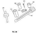
- Figure 28shows some of these system elements: an implantable vertebral plate 100, a cutting tool guide 200, a confirmation device or depth gauge 300, a collar 310 for the confirmation device, a cutting tool 400, an implantable device 500, and an implant locking device 600.
- An implantable vertebral plate 100is adapted to attach to the anterior surface of a vertebra.
- a trajectory control sleeve 200is adapted to detachably mount the implanted bone plate 100 to establish the entry point, trajectory, and depth of an access channel created through the vertebral body.
- a confirmation device 300is adapted to temporarily engage the cutter tool guide for the purposes of confirming placement of the trajectory control sleeve on the correct vertebra, for visualizing the projected trajectory of the bone cutting device, and for measuring the actual distance between the trajectory control sleeve and the anterior bone surface so as to accurately and predictably penetrate through the vertebra without impinging on the dura-mater or other neural tissue at the posterior aspect of the channel.
- the pin-shaped confirmation device 300is typically radio-reflective or radiopaque, thus allowing confirmation of all geometries on a surgical radiograph taken prior to the excision of any tissue.
- a cutting tool 400is generally adapted to remove bone material and create the vertebral access channel; the tool 400 has the precise cutting geometry necessary to produce the prescribed access channel geometry within the vertebral bone.
- the access channelprovides various forms of advantage for aspects of procedures as described further below.
- a surgical cutting instrumentis used to open or partially remove the posterior longitudinal ligament which can obscure a view of the pathology of interest, but becomes observable by way of the access channel.
- a cutting tool used to remove osteophytes (bone spurs) at or adjacent to the base of the vertebral bodycan be approached by way of the access channel proximal to the neural elements to be decompressed.
- An instrument for grasping or moving herniated disc material or other compressing pathologycan be provided access to the site located at or near the base of the access channel.
- An implantable bone repair device 500is adapted to repair the vacant vertebral volume created by the formation of the access channel.
- An implant locking device 600is adapted to retain the implant in the desired position.
- the locking deviceis adapted to positively engage the anterior surface of the repair implant and engagably lock it in place with respect to the implanted bone plate device 100.
- Fastenerssuch as elements 600 (seen in later figures) are applied to retain a bone plate or locking cap (see in other figures) in a desired position.
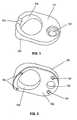
- Figures 1 and 2show anterior and posterior views, respectively, of an implantable transcorporeal bone plate device 100 with a first or anterior facing surface 101 and a second or posterior facing surface 102, the posterior facing surface being configured to be proximal or in contact with the anterior surface of a vertebral body after implantation.
- the devicefurther has one or more holes 103 that form an aperture between surfaces 101 and 102 to accommodate and secure retention screws there to secure the device 100 to vertebral bone.
- Embodiments of implantable bone repair described and depicted hereinare may include a multiple number of orifices, as for example, for inserting attachment elements, or for viewing, that have various sizes and typically are circular or ovular in form. These are merely exemplary forms and profiles of openings which may vary depending on particulars of the application of the device, such that size and profile may vary, and for example, by taking the form of any of circular, trapezoidal, multilateral, asymmetrical, or elongated openings.
- the devicealso has a passage 104 for receiving and detachably-engaging a bone cutting guide device such as a drill or ream.
- the device 100further may have one or more engaging features 105 configured to receive and engage a corresponding feature on the trajectory control sleeve in a manner that prevents relative motion of the trajectory control sleeve and its accidental disengagement from the implanted bone plate.
- the devicemay have one or more protrusions 106 on the posterior surface ( Figure 2 ), the protrusions being adapted to impinge into or through the cortical bone so as to increase the stability of the implant on the bone and to allow for temporary placement of the device prior to insertion of the bone screws through the opening 103.
- Protrusions 106further act to stabilize the bone implant and to transfer loads around the vertebral access channel after a surgical procedure is complete, thereby further reducing the risk of bone fractures or repair device expulsion.
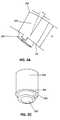
- Figures 3A - 3Cshow a side view and perspective view, respectively, of an embodiment of a trajectory control sleeve 200 for a bone cutting tool, a rotary cutting tool, for example, such as a drill, burr, reamer, or trephine.
- Figure 3Ashows a trajectory control sleeve in a side view
- Figure 3Cshows the trajectory control sleeve from a proximally-directed perspective.
- the trajectory control sleeve 200has an internal cylinder 202 there through to allow passage of a bone-cutting tool, such as a drill or trephine, and to establish and control the angle ⁇ of penetration of the drill through a vertebral body.
- angle ⁇refers to the angular difference from a right angle approach with respect to the plane formed by an implantable bone plate 100 to which the trajectory control sleeve is engaged. More specifically, angle ⁇ can represent a compound angle according to a cranio-caudal axis and a medial lateral axis with respect to a reference plane tangential (such as would be represented by an implanted bone plate) to the access channel entry on the anterior surface of vertebral body.
- the angle ⁇is prescribed by a physician by making use of radiographic images of the spine that focus on the target vertebrae and the underlying pathology that are the subject of surgical or diagnostic interest.
- Figure 3Bprovides a cross sectional view of an exemplary control sleeve 200 , which shows the tilt of the annular ring 203 in accordance with angle ⁇ , and the consequent off-center opening at the base of the trajectory sleeve, which generally aligns with the base of the bone plate when the two components are engaged.
- a transcorporal access channelis formed using a trephine type device such as those provided by Synthes, Inc (West Chester PA), which offers particular advantages.
- the trephine deviceproduces a cylindrical channel through the vertebral bone while maintaining the core to be removed in an intact state.
- the corecan be removed from the trephine after the tool itself has been removed from the vertebral body, and the bone tissue can be subsequently reused as graft volume after the surgical procedure is completed.
- Trajectory control sleeve 200has a surface 201 adapted to be in intimate contact with and be co-planar to an anterior facing surface 101 of a bone plate implant device 100 (after engaging the device, as in Figure 4 ) so as to assure that the axial distance d is well established and controlled.
- the trajectory control sleeve 200further has an annular abutting surface 203 surrounding the opening of the internal cylinder 202 , the surface being adapted to positively engage a corresponding feature such as a flange or collar of the drill so as to prevent its over-penetration into the vertebral body. This abutment may be internal or external to the guide device as shown in Figure 4 and Figure 3A respectively.
- Trajectory control sleeve 200also has an engaging and interlocking feature 204 adapted to detachably-engage a corresponding feature 105 (see Figure 5 ) on the implantable bone plate 100.
- the trajectory control sleeve 200is further generally adapted to protect surrounding vascular and soft tissue from accidental injury or cutting by providing a solid protective sheath around the sharp edges of the drill while it is operating.
- Figures 4 and 5show a perspective view and side view, respectively, of trajectory control sleeve 200 and an implantable bone plate 100 in their mutually interlocked positions.
- Figure 4shows the internal cylinder 202 for providing access, guiding and controlling the penetration of a drill into vertebral bone.
- Figure 4further shows an alternate device that has an abutting surface 203 , in which the abutting surface is internal to the trajectory control sleeve.
- Figure 5shows the planar engagement of the anterior surface of an implanted bone plate 101 with the corresponding surface 201 of the trajectory control sleeve. This engagement establishes a reference plane 210 from which angle ⁇ and distance d are controlled and referenced relative to the vertebral body.
- Figure 5further shows the engagement of the detachable locking features 205 of the trajectory control sleeve and of the bone plate 105.
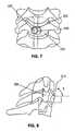
- Figures 6 - 8relate to the placement of a mutually-engaged bone plate 100 and a trajectory control sleeve 200 to a vertebral body 230, in preparation for creating an access channel through the vertebral body.
- Figure 6provides a surface perspective view of bone plate 100 in an implanted position on a vertebral body 230, the plate secured by a bone screw 600, and further shows trajectory control sleeve 200 in its engaged position on the bone plate 100.
- Figure 7shows an anterior view of a bone plate 100 and trajectory control sleeve 200 mutually engaged and, the engaged assembly in it installed position on vertebral body 230.
- a bone screw 600is inserted at or near the medial centerline 231 of the vertebral body 230, thus positioning the center point 220 of the trajectory control sleeve cylinder at a prescribed distance I from the centerline.
- an angle ⁇is the compliment to angle ⁇ shown in Figure 5 .
- the reference plane 210may be delineated relative to the vertebral body 230 and as a baseline reference for the angle and depth of drill penetration into the vertebral body.
- Figures 9A and 9Bshow a pin or plug type confirmation device 300 used for confirming vertebral position prior to excision of bone or other tissue and a collar 310 into which the confirmation device is inserted.
- a standard procedure in spinal surgeryis to insert a radiographically reflective screw or pin into the vertebral body and to take an x-ray of the cervical spine prior to beginning any procedure so as to assure that the procedure is being performed at the correct vertebral level.
- the confirmation device 300is slidably inserted within the internal diameter of the control sleeve 200 and progressed axially therethrough until the proximal end of the device 300 is in contact with the anterior surface of the vertebral body.
- a radiographic imageis taken inter-operatively and reviewed prior to the excision of any vertebral bone tissue.
- the examinationincludes an extrapolation of the trajectory through the vertebral body so as to confirm that the actual point of exit at the posterior surface of the vertebra is at the surgically prescribed location. Further, the axial distance from the both the anterior and/or posterior surfaces of the vertebra are measured and used as references to control the depth of bone cutting necessary to produce the access channel and to prevent over penetration into the dura mater or neural tissue.
- the device 300may be used during the bone cutting procedure as a checking device to determine the actual progression of the channel across the vertebra.
- Figure 9Bshows a trajectory confirmation pin 300 and a collar 310 that slidably-engages the external diameter of the pin by way of features 320 that engage complementary features 321 on the internal diameter of the collar.
- the trajectory pin features 320are convexities that are complementary to concave collar feature 321.
- Collar 310can slide axially along the length of the pin diameter 320 and frictionally-engage the pin diameter in a manner that requires an axial force to be applied to the collar to induce axial movement.
- Collar 310has a surface of engagement feature 330 that is adapted to make intimate contact with the annular surface 203 of the trajectory control sleeve when the pin is inserted into the trajectory control sleeve.
- insertion force F( Figure 9A ) applied by a surgeon causes pin 300 to travel axially through the internal diameter of collar 310 , increasing the distance L2 between point 350 on the tip of the pin and the control surface 330 of the collar 310.
- Figures 10 -12relate to the use of a trajectory confirmation pin 300, a collar 310, and trajectory control sleeve 200 in the context of a bone plate 100 in place, as implanted in a vertebral body 230.
- An embodiment of a pin device 300is temporarily inserted into the internal cylinder of the trajectory control sleeve 200 and an x-ray is taken.
- the x-rayconfirms the location of the vertebral body 230 and an anterior-to-posterior extrapolation along the centerline of the device through the image of vertebral body indicates the trajectory of the drill or cutting tool and the projected point of exit at or near the posterior longitudinal ligament.
- Angular and distance measurementsmay be made using the radiograph, and if adjustments are required, the surgeon disengages the trajectory control sleeve and installs another device with the desired geometry.
- Figure 11shows the confirmation pin 300 at its maximum depth of penetration through the transparently rendered trajectory control sleeve 200 and bone plate implant 100.
- tip 350 of the pin deviceis in intimate contact with the surface of the vertebral bone 230.
- the collarremains in position relative the bone-contacting tip of the pin 350.
- distance L2(see Figure 9A ), as measured between the collar surface 330 and the pin contact tip 350, provides a reference dimension with which the penetrating depth of the bone drill can be controlled by setting a mechanical stop that engages the annular surface 203 of the trajectory control sleeve.
- the surface of the confirmation pin 300may have linear graduations.
- FIG 13shows a bone cutting tool 400, such as a drill, burr, or reamer, inserted through the trajectory control sleeve 200 and the bone plate implant 100 with the tip of the cutting tool 420 at the initial point of contact on the vertebral body.
- Cutting tool 400has a mechanical stop 450.
- the distance D4 from the drill tip 420 to the lower surface 430 of the drill stop 450,is a prescribed dimension equivalent to the measured distance L2 ( see Figure 9A ) plus the desired depth of penetration into the vertebral body, such depth being established by the surgeon through radiographic analysis.
- Figure 14shows a surgical access channel 470 in a vertebral body 230, as viewed through the bone plate implant 100 after drilling has been completed and the trajectory control sleeve has been removed from the plate. After removal of the trajectory control sleeve, a neural decompression or other surgical procedure is performed through the access channel. On completion of the procedure, an intravertebral bone implant 500 is inserted ( Figures 15 and 16 ) into access channel 470 to fill and close it, restore mechanical strength and stability to the host vertebral body 230, and to provide a medium within the vertebral body suitable for osteogenesis.
- the intra-vertebral access channel 470( Figure 14 ) of an implantable bone plate has a diameter of about 5 mm to about 8 mm. This size creates a surgical field that is sufficiently open enough for typical procedures, and is sufficiently large enough to minimize the possibility that the access channel will not intersect the area of neural compression.
- the angle of entry ⁇ provided by the access channelis about 10 - 30 degrees, with the center of the point of entry being generally at mid-point on the cranio-caudal length of the vertebra. While these dimensions are typical, alternative embodiments of bone plate implants may have varying widths and geometries so as to accommodate wide anatomical variations. In various alternative embodiments, trajectory control sleeve devices also may include a wide range of angles and depths for the same reason.
- FIG. 29illustrates a typical access channel 470 that may be formed using a 6 mm drill diameter, about a 10 degree angle of entry, with an entry point on the cranio-caudal centerline of the vertebral body.
- FIG 15shows an intra-vertebral implantable bone repair device 500 positioned for implantation within the vertebra 230 through the bone plate implant 100.
- a bone repair deviceVarious embodiments and features of a bone repair device are described in WO 2009/070607 A1 , entitled “Methods and systems for repairing an intervertebral disk using a transcorporal approach").
- implant 500has an abutting surface 520 adapted to engage with a corresponding surface of the bone plate implant. This arrangement prevents excess penetration of the implant through the access channel and prevents the implant from compressively engaging neural elements.
- Figure 16shows the implantable device 500 in the final installed position relative to the bone plate 100.
- the device 500has a locking mechanism 510, such as a conventional bayonet mount, for engaging the bone plate in order to prevent migration of the implant within or out of the access channel.
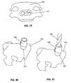
- FIG 17shows an alternative implantable bone plate 620 as previously described and shown in Figures 1 and 2 .
- Bone plate 620has a larger lateral dimension to accommodate particular anatomies that may be encountered, including those of patients, for example, with small stature, degenerative bone conditions, or osteophytes or other abnormalities that may require alternate fixations.
- implant device 620may include a viewing port 650 or some other positioning indicator.
- Figures 18A and 18Bshow anterior perspective and side views, respectively, of the engagement of a trajectory control sleeve 200, as previously described, with the alternative bone implant device 620.
- an implantable bone plate and bone cutting devicemay be formed as a unitary device and temporarily fixed to the vertebral body.
- an intra-vertebral access channelis created using the temporarily implanted device; subsequently, the device is removed, the surgical procedure performed, and the access channel repaired using the intra-vertebral implant as previously described.
- a bone cutting devicemay have a least two cutting diameters or widths, the first being that necessary to produce the access channel, the second being a larger diameter configured to remove an annulus of bone on the anterior vertebral surface so as to provide an abutting surface against which the implant would rest in order to prevent over-penetration of the intra-vertebral repair implant within the vertebra.
- Figures 19 - 24show exemplary devices being put to exemplary use to evaluate the practical viability, fit, and the functionality of methods for their use.
- Figure 19shows an implantable bone plate 100 in situ on a vertebral surface 230.
- Figure 20shows a perspective view of the implantable bone plate and trajectory control sleeve 200 in situ on the vertebral surface.
- Figures 22 - 24include a view of surgeon's finger to show scale and feasibility of manual manipulation of elements of the inventive system.
- Figure 21shows a bone cutting tool 400 engaging vertebral bone tissue through the trajectory control sleeve 200.
- Figure 22shows an access channel 470 through the implanted bone plate and into vertebral bone tissue.
- Figure 23shows an intra-vertebral repair device 500 being readied for engaging vertebral bone through the bone plate 100.
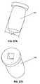
- Figures 25A - 27Bshow embodiments of alternative external geometries of the intra-vertebral implantable devices 500 as may appropriate for particular patients or procedures.
- Figures 25A and 25Bshow views of what may be considered a default embodiment of an intravertebral repair device with a proximal abutting surface orthogonal to the body of the device.
- Figure 25Ashows the device from a proximally-directed perspective
- Figure 25Bshows it from a distally-directed perspective.
- Figures 26A and 26Bshow and embodiment wherein abutting surface 520 is canted at an angle not orthogonal to the central axis of the device 500.
- Figures 27a and 27bshow an intra-vertebral implant device 500 with a convex external profile where dimension D4 is nominally larger than the internal diameter of the access channel so as to compressively engage the cancellous bone tissue. Such a compressive engagement can improve the interference fit of the device therein and to inter-diffuse cancellous bone tissue within the implant volume to improve osteogenesis.
- Figure 28shows an assemblage of some of these system elements, and was described at the outset of the detailed description; shown is an implantable vertebral plate 100, a cutting tool guide 200, a confirmation device or depth gauge 300, a collar 310 for the confirmation device, a cutting tool 400, an implantable device 500, and an implant locking device 600.
- Figure 29provides an exemplary embodiment of the invention that was discussed earlier in the context of the formation of an access channel, in conjunction with associated description of Figures 14 -16 .
- Implantation of the patient's own bone tissueis a generally advantageous approach to repairing bone, as autologous grafting typically yields high success rates and a low rate of surgical complications.
- some embodiments of the inventioninclude using core bone tissue harvested from the forming of the access channel, and implanting the plug, intact, in the form of bone repair graft.
- An advantage to recovering and making use of bone derived from the channelincludes the absence of a need to harvest bone from a second site.
- Embodiments of the inventiondo include harvesting bone from secondary sites on the patient, such as the iliac crest, as may be appropriate in the practice of the invention under some circumstances.
- Bone from other autologous sites or other donor individualsmay be used as a repair device in the form of an appropriately formed plug, or bone may be fragmented or morselized, and packaged as a solid plug, or bone may be included as a preparation provided in a porous cage, as described further below.
- a trephine type bone cutting systemmakes use of a trephine type bone cutting system, as noted above.
- the external diameter of the bone tissue coreis about equal to the internal diameter of the trephine device, while the internal diameter of the access channel is about equal to the external diameter of the device.
- a trephine-derived bone plug from forming the access channelprovides an appropriately-sized piece to be inserted into the channel for repair and healing, but does not necessarily make intimate contact with the inside surface of the channel due to the width of the kerf created by the trephine.
- an embodiment of the bone repair deviceincludes a device with bone tissue inside a porous cage, as described in detail below.
- the porosity of the cageis a particularly advantageous feature for allowing cell to cell contact through the boundary of the device. To some degree, it may also allow cell migration, however the most advantageous factor in promoting rapid healing is cell to cell contact that initiates sites of tissue unification, which can then spread, stabilize a healing zone around the graft or bone repair device, and ultimately lead to effective fusion and integration of the graft within the host vertebral body.
- a porous cagealso has a compressibility, such that when the contents of the cage are subject to a compressive force, however transient and minimal, blood or plasma and bone cells that are present in the harvested cancellous bone are forced outward into the environment within and around the access channel site.
- Extrusion of biological fluid in this manneradvantageously packs bone tissue closer together within the cage, and bathes the periphery of the graft and the host-graft intersectional zone with a medium that is optimal for exchange of dissolved gas and nutrients that are critical in the initial stages of healing.
- Some embodiments of the inventioninclude bathing the bone tissue preparation in a supportive liquid medium before implantation. Such bathing may occur prior to placing the bone tissue preparation in the porous cage and/ or after placing the preparation in the cage.
- the liquid mediummay be any appropriate cell culture medium, and may be further supplemented with biological agents, such as osteogenic agents or other growth factors.
- Embodiments of the implantable porous cage bone repair deviceencapsulate the bone tissue contained therein, and provide mechanical stability to the access channel during healing. These embodiments compensate for the volumetric loss associated with the bone cutting process of the trephine and promote contact between the bone volume within the device and the surrounding vertebral bone tissue.
- the deviceas a whole, and like other bone repair embodiments provided, cooperates with the implanted bone plate so that the orientation and penetration depth of the implant device within the access channel may be controlled. These forms of control assure that the device does not over-penetrate through the channel, thereby compressing the dura mater or neural elements within the vertebra, and assuring that the implanted device cannot migrate in an anterior direction out of the access channel.
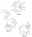
- Figure 30provides a cross-sectional view of a vertebral body 809 with a bone plate 801 attached to the anterior bone surface 810.
- a trajectory control sleeve 802cooperating with the bone plate 801 to establish and control the trajectory of a bone cutting tool 804 with a cutting surface 808 through the vertebral body to direct the trajectory of the formed access channel to a prescribed point of exit at the posterior surface of the vertebra 820, in the locale of a site of medical interest.
- the depicted exemplary bone cutting tool 804is a hollow bone cutting tool, a trephine, with an external diameter 805 selected to be complementary to the internal diameter of the trajectory control sleeve 802, and to cooperate therewith so as to assure that the centerlines of the bone cutting tool and the trajectory control sleeve are substantially co-incident during the bone cutting process.
- the trephine 804progresses through the vertebral body 820 from an anterior to posterior direction until the cutting surface 808 penetrates the cortical bone at the posterior surface of the vertebra proximal to the spinal cord 850.
- a core of bone tissue within the interior of the trephineis extracted from the wound opening, thus creating or exposing an open access channel from the anterior surface of the vertebral body to the neural elements and the prescribed site of medical interest immediately behind the posterior wall of the same vertebral body.
- Figure 31shows components of an exemplary bone repair device in a linearly exploded view from an external perspective.
- a cap 950is above a vertebral bone core 860; the bone core is positioned for placement in a porous cage 900.
- Figure 32is a cross-sectional view of the fully assembled device 905.
- the vertebral bone core 860is placed within an implantable intravertebral bone repair device 900 with a porous wall, and encapsulated by a cap or closing element 950.
- the caphas a screw thread 951 disposed to engage a mating thread 901 on the body 900 of the implantable device; the cap further has a compression element 952 disposed to exert a compressive force F on the bone graft core 860 when the cap is being closed on the body 900 of the repair device, and consequently inducing extrusion of native tissue within the device, through open pores 902 contained within the perimeter wall of the implant device.
- the bone tissue placed within the body of the repair deviceis not necessarily an integral bone plug intact from the trephine used to form the channel; the bone tissue may be a fragmented or morselized preparation, it may include bone from another site on the patient, and it may include bone from another donor.
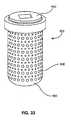
- Figure 33provides an external perspective view of an assembled bone repair device 905. This view captures a moment shortly after the cap 950 has been closed, and by such closing has increased the pressure on the bone tissue contained within the device. By virtue of this elevated pressure within the porous walled body 900, bone core graft tissue and associated biological fluid are extruding through the porous perimeter wall.
- the cap 950may be closed on the porous body 900 of the repair device immediately prior to insertion of the assembled device 905 into the access channel within the host vertebral body. Alternatively, the cap may be closed after insertion of the porous body 900, thereby forming the complete assembly 905 in situ.
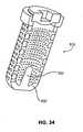
- Figure 34shows a cross sectional view of an alternate embodiment of the porous body portion 900' of an assembled repair device 905' that includes an internal tissue expander feature 920 disposed to induce radial extrusion of the bone core tissue through the orifices.
- Figures 35 and 36show similar views of the porous cage device embodiment 905 as were provided earlier by Figures 15 and 16 for solid bone repair device 500 embodiments.
- Figure 37shows a cross sectional view of the implanted device 905 within an intravertebral access channel 470.
- the bone repair implant assembly 905containing the harvested bone graft core 860
- the bone repair assembly 905has an abutting surface disposed to cooperate with a mating surface of engagement 871 on the bone plate implant. The completed mating of the bone repair assembly 905 with the bone plate 100 prevents the distal tip 890 of the implant assembly from penetrating into the spinal cord volume posterior to the vertebral body.
- the implantable repair device assembly 905further has an orientation and locking feature 951 disposed to engage a mating feature 950 on the implantable bone plate 100 so as to control the radial orientation of the implant with respect to the bone plate and to lockably engage the bone repair implant device with the bone plate implant so as to prevent migration or expulsion of the bone repair implant assembly 905 out of the access channel.
- Such radial orientation of the implant relative to the access channelmay be particularly advantageous when the bottom or distal end of the repair device body 900 is formed at an angle (not shown) to completely fill the access channel.
- the general mechanical integrity of the vertebral bodyhas been restored, the internal void of the access channel has been filled in a manner such that native disc material 980 cannot migrate into the channel, bone tissue (typically autologous) has been re-implanted in a manner that establishes intimate contact between the bone graft and the cancellous bone of the vertebra thereby promoting blood profusion and rapid bone healing.
- bone tissuetypically autologous
Landscapes
- Health & Medical Sciences (AREA)
- Orthopedic Medicine & Surgery (AREA)
- Surgery (AREA)
- Life Sciences & Earth Sciences (AREA)
- Biomedical Technology (AREA)
- Public Health (AREA)
- Veterinary Medicine (AREA)
- Engineering & Computer Science (AREA)
- Nuclear Medicine, Radiotherapy & Molecular Imaging (AREA)
- Heart & Thoracic Surgery (AREA)
- Medical Informatics (AREA)
- Molecular Biology (AREA)
- Animal Behavior & Ethology (AREA)
- General Health & Medical Sciences (AREA)
- Neurology (AREA)
- Dentistry (AREA)
- Oral & Maxillofacial Surgery (AREA)
- Prostheses (AREA)
Description
- The invention relates to devices for use in spinal surgery. More particularly, the invention provides an implant for use in spinal repair surgery and a method, not claimed, for preparing the vertebral volume to receive the implant.
- The performance of cervical discectomy, excision of tissue, and neural element decompression procedures have become standard neurosurgical approaches for the treatment of disorders of the spine and nervous system, as may be caused, for example, by disc degeneration, osteophytes, or tumors. The compressive pathologies impinge onto a neural element, causing a compression of nerve tissue that results in a symptomatic response such as loss of sensation or strength, occurrence of pain, or other related disorders. The majority of these procedures are performed with an anterior approach to the cervical spine. Disc and bone tissue are removed, a neural decompression is achieved, and a spinal repair procedure is performed.
- The current conventional repair procedure includes a vertebral fusion in which a biocompatible implant is inserted and secured between the affected adjacent vertebrae. A bone plate is then is rigidly attached to the two vertebrae adjacent to the implant, immobilizing these vertebral segments and preventing the expulsion of the implant from the intervertebral space. Subsequently, osteogenesis of the vertebrae into the implant occurs, and ultimately the adjacent vertebrae fuse into a single bone mass. The fusion of the vertebral segments, however, can lead to problematic results. For example, the immobility of the fused vertebral joint is commonly associated with the progressive degeneration of the adjacent segments, which, in turn, can lead to degeneration of the intervertebral discs on either side of the fused joint.
- Implantation of an artificial disc device offers an alternate approach to vertebral fusion. The objective of the artificial disc device is to preserve the relative motion of the vertebrae across the joint and to restore normal articulating function to the spinal column. In spite of the benefits that these procedures have brought to patients, both fusion and disc replacement have inherent problems. The surgeries are extensive, recovery time is relatively long, and there is often a loss of function, particularly with the use of fusion implants. The long-term biocompatibility, mechanical stability, and durability of replacement disc devices have not been well established. Further, there is no clinical consensus that the use of a replacement disc reduces the risk of adjacent segment degeneration.
- Methods for surgery on the spine and cervical discs from an anterior approach were first developed in the 1950's, and a number of variations have been developed since then. Each anterior cervical discectomy procedure, however, has had to face the challenge represented by removing the tissue overlaying the compressing lesion (i.e., the herniated disc material, osteophyte or tumor) after having dissected through the soft tissue anterior to the spine. Early procedures exposed the compressing tissue by first making a cylindrical bone-and-disc defect in the spine centered on the disc space in sagittal and coronal planes, and generally following the plane of the disc itself. Later procedures made use of a rectangular, box-like defect in the disc space centered on the disc space and generally following the plane of the disc.
- Procedures recently developed by Jho (referenced below) were motivated by the concern that procedures like those described above destroyed more of the natural disc tissue than was necessary to remove a laterally-positioned disc herniation or osteophyte (a bone spur). An alternative procedure, an uncovertebrectomy, was therefore developed that involved the removal of only the lateral-most aspect of the disc space, and the vertebral bone above and below it, which together comprise the entire uncovertebral joint. (SeeChoi et al., "Modified transcorporeal anterior cervical microforaminotomy for cervical radiculopathy: a technical note and early results", Eur. Spine J. 2007 Jan 3;Hong et al., "Comparison between transuncal approach and upper vertebral transcorporeal approach for unilateral cervical radiculopathy - a preliminary report", Minim Invasive Spine Surgery, 2006 Oct; 49 (5):296-301; andJho et al., "Anterior microforaminotomy for treatment of cervical radiculopathy: part 1: disc-preserving functional cervical disc surgery", Neurosurgery 2002 Nov; 51 (5 Suppl.): S46-53.) This new type of procedure allows much of the disc space to remain untouched. While preserving more of the disc space and disc material than its predecessor procedures, the uncovertebrectomy nevertheless does obliterate the uncovertebral joint, and there is concern in the field regarding the eventual development of spinal instability at that disc level. Further, drilling bone at high speed adjacent to the nearby vertebral artery and sympathetic nerve process increases the concern of a higher risk of vertebral artery, secondary soft tissue injury, and Horner's Syndrome.
- In another refinement of the uncovertebrectomy procedure, an anterior cervical microforamenotomy, the uncinate process and the lateral disc tissue may be left largely intact as a hole is drilled through the bone adjacent to the disc space near the uncinate process. In both uncovertebrectomy and anterior microforamenotomy, the exposure and decompression of the neural elements generally follow the plane of the disc space. While vertebral artery injury and spinal instability remain concerns with both procedures, the risk associated with anterior microforamenotomy is considered less than that of uncovertebrectomy.
- An additional refinement of both uncovertebrectomy and anterior microforamenotomy is a transcorporeal decompression procedure (also referred to as an upper vertebral transcorporeal foramenotomy or a transcorporeal discectomy) may have advantages. This procedure differs from its disc space-preserving precedent procedures in several ways. First, the axis of the access hole drilled to expose the compressing pathology (e.g., herniated disc fragment) doesnot parallel the plane of the disc, but instead entirely avoids the disc space plane anteriorly and captures the disc only at its most posterior aspect. Second, while uncovertebrectomy and anterior cervical microforamenotomy are applicable only to lateral pathology, the transcorporeal decompression is potentially applicable to compressing pathology located laterally in the disc space region, bilaterally, or in the midline. Further, the procedure is performed from a substantially medial position on the vertebra assuring maximal distance from the vertebral artery and other sensitive soft tissue and thereby minimizing the risk of accidental injury.
- Multiple technical challenges remain, however, in optimizing the transcorporeal cervical decompression procedure for general surgical use. First, manually orienting and controlling a hand-held cutting tool to make an access channel is a subjective and error-prone procedure. The target pathology is wholly behind and/or within the bony structure of the vertebra and is not visible in any way when approached from a traditional anterior approach to the cervical spine. As the channel is essentially being driven blindly, it can easily fail to capture the targeted pathology being within the range of the posterior opening of the access channel. Consequently the surgeon needs to prolong the procedure, and explore the space by excising tissue until the pathology is found. The exploration typically leads to the access channel becoming larger than necessary and undesirably irregular, thus putting surrounding bone at risk of fracturing during or after the procedure. Given the proximity of many target pathologies to the uncovertebral joint and the vertebral artery, it is likely that exploration of the space will lead to removal of the stabilizing bone and disc tissue. This tissue damage or loss can cause spinal instability, and may further result in accidental perforation of the vertebral artery.
- Second, a manual drilling process increases the risk of over penetration into the spinal canal, with highly undesirable consequences.
- Third, the posterior longitudinal ligament, once exposed in the access channel, can be difficult to open. The objective is to remove the ligament cleanly from the access channel area so as to provide unobstructed visualization of the compressed neural tissue. Current surgical techniques are subjective and time-consuming, often producing a shredding of the ligament within the access channel rather than its removal therefrom, thereby impeding the visualization of the underlying target pathology or dura mater protective layer.
- Fourth, currently available microsurgical instruments are not well-suited for retrieving the herniated disc or bone fragments that may be found deep to the posterior longitudinal ligament.
- Fifth, after the decompression is complete, the present solutions for filling the void remaining in the vertebra are not completely satisfactory. Demineralized bone matrix putties or similar materials can fill the defect but they offer no resistance to the normal compressing or torsional forces until calcification occurs. Such materials may also impose a new source of compression on the exposed neural structures if too much putty is applied or if the vertebra deforms or sustains a compression fracture subsequently because of the absence of an implant that sufficiently resists compressive forces.
- Sixth, after a solid implant plug is placed in the surgically-formed access channel, there is presently no anterior cervical plate suited to preventing its outward migration. Currently available anterior cervical plates are designed to be placed across two or more adjacent vertebrae at or near the midline, not laterally, as would be needed for lateral compressing lesions. Existing plates also are designed as motion-restriction or motion-prevention devices to be placed bridging across a disc space rather than onto a single vertebral body, consequently they are too large and are counterproductive in the application such as that described above where the objective is to preserve the articulation and relative motion of the adjacent vertebrae.
- Accordingly, there is a need for a system and method whereby any compressing spinal pathology may be removed or moved so as to decompress the neural elements involved while desirably also (1) preserving native disc and bone tissue and the natural motion of the spine with natural disc material, (2) minimizing the risk of injury to the vertebral artery, (3) minimizing the risk of structural spinal instability, (4) minimizing the risk of an inadequate decompression, (5) minimizing the risk of injury to the protective dura mater layer, (6) minimizing the risk of post operative bleeding and/or (7) minimizing the risk of a subsequent vertebral body fracture due to an unrepaired defect within it.
US 2002/058944 A1 discloses a device for use in a vertebral spine to prepare a space between adjacent vertebral bodies to receive an implant. The device includes a shaft, and a mounting member at one end of the shaft. A working end is mounted on the mounting member and is coupled to a drive mechanism adjacent to the working end. The drive mechanism is operable to move the upper and lower cutters of the working end to create surfaces having predetermined contours in the end plate region of the adjacent vertebral bodies. A guard provides protected access to the disc space and the adjacent vertebral bodies for the working end of the bone removal device through a passageway.US 5 741 253 A discloses a method for inserting an implant across the disc space and into two adjacent vertebrae through a tubular member. The method comprises the steps of: inserting a tubular member having means to engage said two adjacent vertebrae; placing through said tubular member a drill having a diameter greater than said disc space; drilling an opening across the disc space and into a portion of each of the two adjacent vertebrae through said tubular member; removing said drill; inserting an implant in the opening through the tubular member; and then removing said tubular member.US 2007/203500 A1 discloses an apparatus and method for shaping an intervertebral space. A device for creation of a cavity between two bone surfaces comprises: a spacing mechanism for placement between said bone surfaces; one or more guide mechanisms disposed on said spacing mechanism within said cavity for controlling a bone cutting device; and a means for controlling the placement of the device by abutting one or more of the bone surfaces.US 2003/083667 A1 discloses a polyaxial drill guide that includes a body, a collet and a stem. The collet includes a collet shaft having distal and proximal ends and a longitudinal bore. The body includes a conical bore having narrow and wide ends. The distal end of the collet shaft rotatably mounts within the narrow end of the conical bore, with the collet shaft extending toward the wide end of the conical bore, such that the collet shaft (and consequently the longitudinal bore) can be angled within the conical bore at a plurality of angles. The stem includes a shaft having distal and proximal ends and a longitudinal bore. The distal end of the stem shaft mounts to the proximal end of the collet shaft such that the longitudinal bores are co-linear and a drill bit can be inserted into and rotated within the longitudinal bores during a drilling procedure.US 2003/065329 A1 discloses a vertebral stabilization assembly for stabilizing vertebrae. The vertebral stabilization assembly includes a first and a second pedicle screw, a first and second connecting screw, and a connecting member. The first and second pedicle screws each have a shaft provided with a threaded portion operable for threading engagement of the first and second pedicle screws with a first and second vertebra, respectively, each shaft also has an engaging portion. The first and second connecting screws each have a first end adapted to be received by the engaging portions of the first and second pedicle screws, respectively. The connecting member has a first end connected to the first connecting screw and a second end connected to the second connecting screw for stabilization of the first and second vertebra. A guide member for placement of the connecting screw and method for anteriorly stabilizing vertebrae is also provided.- According to the present invention there is provided the surgical system of claim 1.
- Additional aspects of the surgical system are set out in the dependent claims.
- Whilst the following description references various methods and procedures, these methods or procedures do not form part of the present invention, but represent background art that may be useful for understanding the invention.
- There are hereinafter described and illustrated systems and methods for forming and repairing an access channel through a vertebral body, typically a cervical vertebral body, for the purpose of gaining access to a site in need of a medical intervention. In its formation, the channel originates on the anterior surface of the vertebral body, and it then provides access from the anterior approach. The channel follows a prescribed trajectory to a prescribed exit on the posterior surface of the vertebral body, and provides an opening at the site of sufficient size to address the medical need. The access channel is typically formed in cervical vertebral bodies. The nature of the medical need typically includes the need for a decompression procedure, as may occur as a result of a problematic portion or the whole of a herniated disc, an osteophyte, a thickened ligament, a tumor, a hematoma, a degenerative cyst, or any other compressing pathology. The medical intervention may be as minimal as observing the site, or performing exploration, or it may include a diagnostic procedure, or delivering a therapy, or it may include a surgery. A typical surgery performed through the access channel can include decompressing a neural element, such an individual nerve root, a spinal cord, or a cauda equina.
- There is also hereinafter described and illustrated an implantable bone repair device having an external geometry complementary to the internal geometry of the access channel, and a method for repairing or healing the channel by implanting such device. Some embodiments of the device include materials that are biocompatible, biologically absorbable, or any material known to be able to substitute for bone, and to be able to be stably and effectively integrated into bone. The device may further include as well as biologically active agents, such as osteogenic agents, that promote healing of the wound represented by the access channel, and fusion of the device such that it integrates into the vertebral body.
- In some embodiments, the implantable bone repair device includes an assembly with a porous body that includes actual bone tissue. Such bone tissue may be provided by the bone removed during the formation of the channel itself, or it may come from another site from the patient as an autologous graft, or it may be provided by a separate donor.
- The system to form and repair an access channel includes a bone cutting tool with a cutting element, a bone plate configured to be secured to the anterior surface of the vertebral body and having an opening sized to receive the cutting element; and a trajectory control sleeve configured to detachably engage the bone plate and having a cylinder configured to receive the cutting element. The bone plate and the trajectory control sleeve, when mutually engaged, are configured to cooperate to guide the cutting element to form the access channel with a prescribed trajectory from the anterior entry to the prescribed posterior opening.
- There are also hereinafter described and illustrated methods for prescribing of the point of anterior entry and the channel trajectory toward the posterior opening are typically provided by a physician who observes the cervical spine of the patient radiographically. From such observation of patient anatomy and the site of pathological interest, the physician prescribes a trajectory according to a cranio-caudal axis and a medial lateral axis with respect to a point of entry on the anterior surface of vertebral body. Such radiographic observation may occur before the attachment of the bone plate, to be summarized below, and/or after the attachment of the bone plate.
- Returning to summarizing the system for forming the access channel, some embodiments include fixation elements to secure the bone to the anterior surface of the vertebral body. The bone plate may include openings to accommodate fixation elements to secure the bone plate to the anterior surface of the vertebral body. In some embodiments, the bone plate and fixation elements are configured of a biocompatible material. In some embodiments, the bone plate and the fixation elements have a composition and structure of sufficient strength that that the bone plate may be permanently implanted.
- Embodiments of the trajectory control sleeve may be configured to direct the bone cutting tool on a trajectory prescribed by the method above, the prescribed trajectory being an angle according to a cranio-caudal axis and a medial lateral axis with respect to a reference plane tangential to the access channel entry on the anterior surface of vertebral body.
- Embodiments of the bone plate provide a reference plane such that the trajectory control sleeve, when secured to the bone plate, may be configured with a range of angles formed on two axes with respect to the plane of the bone plate, a cranio-caudal axis and a medial lateral axis, the range of the angles varying between about 1 degree and about 30 degrees from an angle perpendicular to the plate. In typical embodiments, the range of the angles varies between about 10 degrees and about 30 degrees from the perpendicular angle. In some embodiments, the system includes a plurality of trajectory control sleeves, the sleeves varying in regard to angles formed with respect to a plane represented by the bone plate when secured thereto, the angles ranging between about 10 degrees and about 30 degrees cranio-caudally from a perpendicular angle.
- In some embodiments, the trajectory control sleeve and the bone plate have mutually-engageable features that orient the engagement of the trajectory control sleeve on the bone plate in a configuration that allows the trajectory control sleeve to guide the cutting tool into the vertebral body with the prescribed trajectory. And in some embodiments, the trajectory control sleeve includes a contact surface for engaging a corresponding surface on the bone cutting tool, the surfaces configured so as to limit the penetration of the cutting tool into the vertebral body to a prescribed depth.
- In some embodiments, the posterior surface of the bone plate includes one or more penetrating elements configured to impinge into the vertebral bone tissue to improve fixation and resist the torsional forces associated with bone cutting procedures. In some embodiments, the bone plate includes an anatomically-orienting feature to establish the position of the bone plate relative to the medial centerline of the vertebral body. In some embodiments, the bone plate includes a biocompatible material. And in some embodiments, at least a posterior surface of the bone plate is of sufficiently porous composition to support in-growth of bone.
- In various embodiments, the bone-cutting tool is any of a drill, a reamer, a burr, or cylindrical cutting tool, such as a core cutter or a trephine. In some of these embodiments, the cutting element of the bone-cutting tool has a cutting diameter of between about 5 mm and about 7 mm.
- As noted above, embodiments of the implantable bone repair device have an external geometry complementary to the internal geometry of the access channel. These bone repair device embodiments may be sized to be insertable through an opening of the bone plate, the opening also being sized to receive the bone cutting element. In some embodiments, the bone repair device includes an abutting surface configured to engage a corresponding surface of the bone plate through which it is implanted, the engagement of these surfaces adapted to prevent the bone repair device from penetrating too deeply into or through the access channel of the vertebral body. In some embodiments, the bone repair device includes receiving features in or on its anterior surface configured to accommodate the attachment of an insertion tool.
- In some of these embodiments, bone repair device and the bone plate have mutually engageable orientation and locking features. In various embodiments, the locking engagement results from the application of an axial force to snap the locking feature into a corresponding retaining feature of the bone plate. In other embodiments, the locking engagement results from the application of a torsional force to engage the locking feature into a corresponding retaining feature in or on the bone plate.
- In some embodiments of the surgical system the bone repair device comprises a porous cage with a porosity sufficient to permit through movement of biological fluids, such as blood, and bone cells. The composition of the porous cage portion of the device may include any of a polymer, a metal, a metallic alloy, or a ceramic. An exemplary polymer may polyetheretherketone (PEEK), which may be present in the form of PEEK-reinforced carbon fiber, or hydroxyapatite-reinforced PEEK. In some embodiments of the bone repair device with a porous cage, the porous cage device includes a closeable opening through which harvested bone material (such a native bone from the access channel site) may be passed. And in some of these embodiments, the porous cage device includes a closeable cap configured to increase pressure on the harvested bone within the cage as the cap is closed. Further, some embodiments include an internal element adapted to enhance compressive force applied to the contents of the porous cage upon application of compressive force to the cage, such force inducing extrusion of harvested bone and blood from within the cage through its porous structure to the external surfaces of the cage.
- Some embodiments of the surgical system include a trajectory and depth visualization device. In some of these embodiments, the trajectory and depth visualization device includes a radio-reflective feature so as to confirm the location of the bone plate device on the appropriate vertebral body and to facilitate the extrapolation of the projected trajectory of the bone cutting tool using a radiographic image. In some embodiments, the trajectory and depth visualization device includes visual markings to indicate the distance from the point of contact with the vertebral body and cutter penetration control feature on the bone cutter guide device.
- A method for performing a procedure through a vertebral body overlaying a site in need of a medical procedure includes attaching the bone plate on the anterior surface of the vertebral body, engaging the trajectory control sleeve to the bone plate, inserting a bone cutting tool through the trajectory control sleeve, and forming an access channel body by removing bone with the bone cutting tool (the channel having a centerline co-incident with the centerline of the trajectory control sleeve through the vertebral), disengaging the trajectory control sleeve from the bone plate, and performing the medical procedure through the open space provided by the access channel and the opening on the posterior surface of the vertebral body.
- The access channel follows a prescribed trajectory from an anterior entry point to a prescribed opening on a posterior surface of the vertebral body in the locale of the site in need of the medical procedure. The prescription for the points of entry and exit and the vectors of the access channel are determined by radiographic observations and measurements, as summarized above. In some embodiments of the method, forming the access channel includes forming the channel with a constant, circular cross-section along a single, straight axis aligned with the trajectory control sleeve.
- Before engaging the trajectory control sleeve to the bone plate, the method may include selecting the sleeve to be used in the procedure such that when the sleeve and the bone plate are engaged, the sleeve has an angular orientation relative to the bone plate that is consistent with the prescribed trajectory of the access channel. Further, before attaching the bone plate to an anterior vertebral surface, the method may include exposing one or more vertebral bodies in a spinal column by anterior incision. Further still, after performing the medical procedure, the method may include leaving the bone plate attached to the vertebral body.
- In some methods, after engaging the trajectory control sleeve to the bone plate, the method may include inserting a radiopaque locating device into the trajectory control sleeve device, radiographically observing the locating device and determining therefrom an extrapolated trajectory of the access channel toward the posterior surface of the vertebral body, and verifying that the extrapolated trajectory is consistent with the prescribed trajectory such that the point of exit at the posterior surface is proximal to the targeted site of interest.
- In some methods, after engaging the trajectory control sleeve to the bone plate, the method may include inserting a depth-measuring device into the trajectory control sleeve device to establish an optimal depth of penetration of the bone-cutting tool into the vertebral body, the depth being influenced by the disposition of the bone plate against a variable topography of the anterior surface of the vertebral body.
- In some methods, after the completing the medical procedure through the access channel, the method further includes repairing the access channel with an implantable bone repair device, the device having an external geometry complementary to the internal geometry of the channel. In typical embodiment of the method, repairing the access channel includes implanting the bone repair device through the bone plate and into the channel. And in some of these embodiments, the method includes securing a proximal portion of the bone repair device to the bone plate.
- In some methods repairing the access channel includes in-growing bone from the vertebral body into at least a portion of the surface of the bone repair device. And in some embodiments, repairing the access channel includes stimulating bone growth within the bone repair device by providing an osteogenic agent within the repair device.
- In some methods, repairing the access channel includes placing a portion of harvested native bone tissue within a bone repair device that comprises a porous cage. In these embodiments, the method may further include allowing or promoting intimate contact between the bone tissue within the bone repair device and bone tissue of the vertebral body. The method may further include perfusing at least some bone tissue or bone-associated biological fluid from the bone repair device into the vertebral body. Still further, the method may include healing together the harvested native bone tissue within the bone repair device and bone tissue of the vertebral body.
- In the system of the present invention the bone plate and the trajectory control sleeve are an integrated device. In this embodiment, thus the system includes a bone cutting tool with a cutting element and an integrated device comprising a bone plate portion and trajectory control sleeve portion. The bone plate portion is configured to be secured to an anterior surface of the vertebral body and has an opening sized to receive the cutting element. The trajectory control sleeve portion has a cylinder configured to receive the cutting element of the bone cutting tool, and the integrated device is configured to guide the bone cutting tool to form the access channel with a prescribed trajectory from the anterior entry to the prescribed posterior opening.
- A method for performing a procedure through a vertebral body overlaying a site in need of a medical procedure with the integrated device summarized above includes attaching the integrated device on an anterior surface of the vertebral body, inserting a bone cutting tool through the trajectory control sleeve portion of the device, forming an access channel through the vertebral body by removing bone with the bone cutting tool, the access channel prescribed as summarized above, disengaging the integrated device from the bone plate, and performing the medical procedure through the access channel and the opening on the posterior surface of the vertebral body.
- In some embodiments of the system, the bone plate or integrally formed bone plate portion does not lie directly over the anterior entry location for the access channel. Rather, the bone plate or bone plate portion is attached to the anterior surface of the vertebral body adjacent to the entry location, and supports a trajectory control sleeve or sleeve portion which may be located adjacent to the entry location.
- Embodiments of surgical system in accordance with the present will now be described, by way of example only, with reference to the accompanying drawings. None of the Figures illustrates a surgical system that is exactly in accordance with the present invention, due to the illustrated devices all having non-integrated bone attachment portions and trajectory control sleeve portions. Nevertheless, these Figures represent technical background that is useful for understanding the surgical system of the present invention, in which the bone attachment portion and the trajectory control sleeve portion are an integrated device.
Figure 1 is a view of an implantable bone plate device viewed from an anterior perspective.Figure 2 is a view of an implantable bone plate device viewed from a posterior perspective.Figures 3A and3B provide views of a trajectory control sleeve attachment.Figure 3A shows a trajectory control sleeve in a side view.Figure 3B provides a side cross-sectional view of the trajectory control sleeve, showing how the angle of the sleeve relative to its base forms an asymmetrical opening in the base.Figure 3C shows the trajectory control sleeve from a proximally-directed perspective.Figure 4 is an anterior perspective of the trajectory control sleeve mounted to an implantable bone plate.Figure 5 is a lateral view of the trajectory control sleeve mounted to an implantable bone plate.Figure 6 is a perspective view showing an implanted bone plate screwed a vertebral body and with a trajectory control sleeve mounted thereon.Figure 7 is an anterior view showing an implanted bone plate screwed to a vertebral body and a trajectory control sleeve mounted thereon.Figure 8 is a lateral view showing an implanted bone plate screwed to a vertebral body and with a trajectory control sleeve mounted thereon.Figures 9A - 9B show various views of a trajectory pin and a drill depth gauge.Figure 9A is a perspective view of a trajectory pin and a drill depth gauge assembled togetherFigure 9B is a perspective view of an embodiment of the depth gauge sub-assembly.Figure 10 is a lateral view of the trajectory pin assembly shown inFigure 9A engaged in a trajectory control sleeve.Figure 11 is a cross sectional view showing a trajectory pin in full engagement with vertebral bone and a trajectory control sleeve.Figure 12 is an anterior perspective view of a trajectory pin and depth gauge engaged within a trajectory control sleeve.Figure 13 is a cross section view showing a bone drill in position relative to a bone plate and trajectory control sleeve prior to cutting bone tissue.Figure 14 is a perspective view of a bone plate after drilling has been completed and the trajectory control sleeve has been disengaged from the implanted bone plate.Figure 15 is a perspective view of a spinal repair implant in the pre-insertion position relative to the implanted bone plate.Figure 16 is a perspective view of a spinal repair implant installed into an access channel through an implanted bone plate.Figure 17 is an anterior perspective view of an alternate embodiment of an implantable bone plate.Figures 18A and18B are views of the trajectory control sleeve mounted on the bone plate embodiment ofFigure 17 . Figure 18A shows the trajectory control sleeve and bone plate from distally directed perspective.Figure 18B shows the trajectory control sleeve and bone plate from a side view.Figure 19 shows an implantable bone platein situ on a vertebral surface.Figure 20 shows a perspective view of an implantable bone plate and trajectory control sleevein situ on the vertebra surface.Figure 21 shows a drill cutter engaging vertebral bone tissue through the trajectory control sleeve.Figure 22 shows an access channel through an implanted bone plate and into vertebral bone tissue.Figures 23 and 24 show an intra-vertebral repair device engaging vertebral bone through the bone plate.Figure 23 shows the repair device being held by a surgeon immediately prior to inserting into the access channel.Figure 24 shows the surgeon's finger pressing the repair device through the bone plate and into the access channel.Figures 25A and 25B show views of an intravertebral repair device embodiment with a proximal abutting surface orthogonal to the body of the device.Figure 25A shows the device from a proximally-directed perspective.Figure 25B shows the device ofFigure 25A from a distally-directed perspective.Figures 26A and 26B show views of an intravertebral repair device embodiment with a proximal abutting surface canted with respect to main axis of the body of the device.Figure 26A shows the device from a side view.Figure 26B shows the device ofFigure 26A from a proximally-directed perspective.Figures 27A and 27B show views of an intravertebral repair device embodiment with a convex external profile, wider in its central portion, narrower at proximal and distal ends.Figure 27A shows the device from a proximally-directed perspective.Figure 27B shows the device ofFigure 27A from a distally-directed perspective.Figure 28 shows the primary components of an exemplary system associated with the creation and repair of the intra-vertebral access channel.Figure 29 shows a typical access channel that may be produced with the inventive systems and methods.Figure 30 shows a cross sectional view of an access channel being formed in a vertebral body with a hollow cutting tool, a trephine, which forms an access channel with a removal bone plug.Figure 31 shows an exploded view of a bone repair device with a porous body configured to hold bone tissue, and to allow compression of the tissue upon closing the porous body.Figure 32 shows a cut away cross sectional view of the bone repair device ofFigure 31 in assembled form.Figure 33 shows an external view of the assembled bone repair device ofFigure 33 with bone tissue and associated fluid being extruded under pressure.Figure 34 shows an alternative embodiment of an assembled bone repair device with a porous body and with an internal pressure-amplifying feature.Figure 35 shows a bone repair device with a porous body containing bone tissue poised in a position from where it is about to be implanted in an access channel within a vertebral body.Figure 36 shows the bone repair device offigure 35 implanted in the vertebral body, and locked into a bone plate.Figure 37 shows a lateral cross sectional view of a bone repair device with a porous body containing bone tissue, in situ, within an access channel in a host vertebral body.- An inventive surgical system and associated method of use are provided for transcorporeal spinal procedures that create and use an anterior approach to an area in need of surgical intervention, particularly areas at or near a site of neural decompression. Removal or movement of a source of compressing neural pathology is achieved via a surgical access channel created through a single vertebral body instead of through a disc space or through an uncovertebral joint (involving 1 or 2 vertebrae). The access channel has a specifically prescribed trajectory and geometry that places the channel aperture at the posterior aspect of the vertebra in at or immediately adjacent to the targeted compressing pathology, thus allowing the compressing neural pathology to be accessed, and removed or manipulated. The access channel is formed with precise control of its depth and perimeter, and with dimensions and a surface contouring adapted to receive surgical instruments and an implanted bone repair device.
- The channel may be used to access and operate on the compressing pathology, more particularly to remove or to move a portion or the whole of a herniated disc, an osteophyte, a thickened ligament, a tumor, a hematoma, a degenerative cyst, or any other compressing pathology. As a part of the procedure, the posterior longitudinal ligament posterior to the transcorporeal access channel may be opened or removed through the access channel, thereby permitting the visualization or removal of any compressing pathology otherwise obscured by the ligament.
- The invention preserves native bone and disc tissue that is sacrificed by prior art procedures, and further preserves the natural motion of the vertebral joint. The procedure also preserves at least the anterior half of the vertebral endplate of the vertebral body upon which the cutting occurs. Removal or the movement of the compressing pathology can proceed even when a portion of the compressing pathology resides beyond the limits of the transcorporeal access channel. Further, removal of the compressing pathology may occur without inducing posterior or inward compression on the dura mater protective layer surrounding the spinal cord and exiting nerve roots, or exerting direct pressure on the spinal cord or exiting nerve roots. Also, the compressing pathology removal may occur without lacerating the dura mater protective layer surrounding the spinal cord and exiting nerve roots.
- Embodiments of the system also pertain to therapeutic occupation and repair of the vertebral body void created by making such an access channel. This repair is achieved by inserting an implantable vertebral repair device that has a conformation complimentary to the internal geometry of the access channel after the procedure is complete, and by securing the implant in the inserted position by means of a vertebral bone plate. The external surface of the vertebral repair device is in substantial contact with the internal surface of the access channel after insertion is complete, thereby substantially restoring structural and mechanical properties of the vertebrae. Such repair occurs without directly or indirectly inducing compression of underlying dura mater or neural structures. The repair further occurs without the subsequent anterior migration of the vertebral repair device, which could cause injury to soft tissue structures located anterior to the spine.
- In some embodiments, the implanted device has a bioabsorbable composition that allows replacement of the implant device by in-growth of native bone tissue, or which is incorporated into the native bone tissue. As a whole the system increases the objectivity of considerations associated with spinal surgery, reduces patient risk, and contributes to better and more predictable surgical outcomes.
- Various aspects and features of the invention will now be described in the context of specific examples and with the illustrations provided by
Figures 1- 37 . - A number of tools and instruments are included in or used within the system and methods described herein.
Figure 28 shows some of these system elements: an implantablevertebral plate 100, acutting tool guide 200, a confirmation device ordepth gauge 300, acollar 310 for the confirmation device, acutting tool 400, animplantable device 500, and animplant locking device 600. - An implantable
vertebral plate 100 is adapted to attach to the anterior surface of a vertebra. Atrajectory control sleeve 200 is adapted to detachably mount the implantedbone plate 100 to establish the entry point, trajectory, and depth of an access channel created through the vertebral body. Aconfirmation device 300 is adapted to temporarily engage the cutter tool guide for the purposes of confirming placement of the trajectory control sleeve on the correct vertebra, for visualizing the projected trajectory of the bone cutting device, and for measuring the actual distance between the trajectory control sleeve and the anterior bone surface so as to accurately and predictably penetrate through the vertebra without impinging on the dura-mater or other neural tissue at the posterior aspect of the channel. The pin-shapedconfirmation device 300 is typically radio-reflective or radiopaque, thus allowing confirmation of all geometries on a surgical radiograph taken prior to the excision of any tissue. - A
cutting tool 400 is generally adapted to remove bone material and create the vertebral access channel; thetool 400 has the precise cutting geometry necessary to produce the prescribed access channel geometry within the vertebral bone. The access channel provides various forms of advantage for aspects of procedures as described further below. - A surgical cutting instrument is used to open or partially remove the posterior longitudinal ligament which can obscure a view of the pathology of interest, but becomes observable by way of the access channel. A cutting tool used to remove osteophytes (bone spurs) at or adjacent to the base of the vertebral body can be approached by way of the access channel proximal to the neural elements to be decompressed. An instrument for grasping or moving herniated disc material or other compressing pathology can be provided access to the site located at or near the base of the access channel.
- An implantable
bone repair device 500 is adapted to repair the vacant vertebral volume created by the formation of the access channel. - An
implant locking device 600 is adapted to retain the implant in the desired position. The locking device is adapted to positively engage the anterior surface of the repair implant and engagably lock it in place with respect to the implantedbone plate device 100. Fasteners such as elements600 (seen in later figures) are applied to retain a bone plate or locking cap (see in other figures) in a desired position. - Each of these aforementioned system elements and their role in surgical procedures on the spine are described in further detail below.
Figures 1 and 2 show anterior and posterior views, respectively, of an implantable transcorporealbone plate device 100 with a first or anterior facingsurface 101 and a second or posterior facingsurface 102, the posterior facing surface being configured to be proximal or in contact with the anterior surface of a vertebral body after implantation. The device further has one ormore holes 103 that form an aperture betweensurfaces device 100 to vertebral bone.- Embodiments of implantable bone repair described and depicted herein are may include a multiple number of orifices, as for example, for inserting attachment elements, or for viewing, that have various sizes and typically are circular or ovular in form. These are merely exemplary forms and profiles of openings which may vary depending on particulars of the application of the device, such that size and profile may vary, and for example, by taking the form of any of circular, trapezoidal, multilateral, asymmetrical, or elongated openings.
- The device also has a
passage 104 for receiving and detachably-engaging a bone cutting guide device such as a drill or ream. Thedevice 100 further may have one or moreengaging features 105 configured to receive and engage a corresponding feature on the trajectory control sleeve in a manner that prevents relative motion of the trajectory control sleeve and its accidental disengagement from the implanted bone plate. The device may have one ormore protrusions 106 on the posterior surface (Figure 2 ), the protrusions being adapted to impinge into or through the cortical bone so as to increase the stability of the implant on the bone and to allow for temporary placement of the device prior to insertion of the bone screws through theopening 103.Protrusions 106 further act to stabilize the bone implant and to transfer loads around the vertebral access channel after a surgical procedure is complete, thereby further reducing the risk of bone fractures or repair device expulsion. Figures 3A - 3C show a side view and perspective view, respectively, of an embodiment of atrajectory control sleeve 200 for a bone cutting tool, a rotary cutting tool, for example, such as a drill, burr, reamer, or trephine.Figure 3A shows a trajectory control sleeve in a side view, whileFigure 3C shows the trajectory control sleeve from a proximally-directed perspective. Thetrajectory control sleeve 200 has aninternal cylinder 202 there through to allow passage of a bone-cutting tool, such as a drill or trephine, and to establish and control the angle α of penetration of the drill through a vertebral body. As seen inFigure 3A the angle α refers to the angular difference from a right angle approach with respect to the plane formed by animplantable bone plate 100 to which the trajectory control sleeve is engaged. More specifically, angle α can represent a compound angle according to a cranio-caudal axis and a medial lateral axis with respect to a reference plane tangential (such as would be represented by an implanted bone plate) to the access channel entry on the anterior surface of vertebral body. The angle α is prescribed by a physician by making use of radiographic images of the spine that focus on the target vertebrae and the underlying pathology that are the subject of surgical or diagnostic interest. Such procedures are typically performed prior to surgery, and they may be repeated after the bone plate is attached to the surgical site.Figure 3B provides a cross sectional view of anexemplary control sleeve 200, which shows the tilt of theannular ring 203 in accordance with angle α, and the consequent off-center opening at the base of the trajectory sleeve, which generally aligns with the base of the bone plate when the two components are engaged.- In some embodiments of the system, a transcorporal access channel is formed using a trephine type device such as those provided by Synthes, Inc (West Chester PA), which offers particular advantages. The trephine device produces a cylindrical channel through the vertebral bone while maintaining the core to be removed in an intact state. The core can be removed from the trephine after the tool itself has been removed from the vertebral body, and the bone tissue can be subsequently reused as graft volume after the surgical procedure is completed.
Trajectory control sleeve 200 has asurface 201 adapted to be in intimate contact with and be co-planar to an anterior facingsurface 101 of a bone plate implant device100 (after engaging the device, as inFigure 4 ) so as to assure that the axial distanced is well established and controlled. Thetrajectory control sleeve 200 further has an annularabutting surface 203 surrounding the opening of theinternal cylinder 202, the surface being adapted to positively engage a corresponding feature such as a flange or collar of the drill so as to prevent its over-penetration into the vertebral body. This abutment may be internal or external to the guide device as shown inFigure 4 andFigure 3A respectively.Trajectory control sleeve 200 also has an engaging and interlocking feature204 adapted to detachably-engage a corresponding feature105 (seeFigure 5 ) on theimplantable bone plate 100. Thetrajectory control sleeve 200 is further generally adapted to protect surrounding vascular and soft tissue from accidental injury or cutting by providing a solid protective sheath around the sharp edges of the drill while it is operating.Figures 4 and 5 show a perspective view and side view, respectively, oftrajectory control sleeve 200 and animplantable bone plate 100 in their mutually interlocked positions.Figure 4 shows theinternal cylinder 202 for providing access, guiding and controlling the penetration of a drill into vertebral bone.Figure 4 further shows an alternate device that has anabutting surface 203, in which the abutting surface is internal to the trajectory control sleeve.Figure 5 shows the planar engagement of the anterior surface of an implantedbone plate 101 with thecorresponding surface 201 of the trajectory control sleeve. This engagement establishes areference plane 210 from which angle α and distanced are controlled and referenced relative to the vertebral body.Figure 5 further shows the engagement of the detachable locking features205 of the trajectory control sleeve and of thebone plate 105.Figures 6 - 8 relate to the placement of a mutually-engagedbone plate 100 and atrajectory control sleeve 200 to avertebral body 230, in preparation for creating an access channel through the vertebral body.Figure 6 provides a surface perspective view ofbone plate 100 in an implanted position on avertebral body 230, the plate secured by abone screw 600, and further showstrajectory control sleeve 200 in its engaged position on thebone plate 100.Figure 7 shows an anterior view of abone plate 100 andtrajectory control sleeve 200 mutually engaged and, the engaged assembly in it installed position onvertebral body 230. Abone screw 600 is inserted at or near the medial centerline231 of thevertebral body 230, thus positioning thecenter point 220 of the trajectory control sleeve cylinder at a prescribed distanceI from the centerline. As seen inFigure 8 , an angle β is the compliment to angle α shown inFigure 5 . After installation of thebone plate implant 100 on avertebral body 230, thereference plane 210 may be delineated relative to thevertebral body 230 and as a baseline reference for the angle and depth of drill penetration into the vertebral body.Figures 9A and 9B show a pin or plugtype confirmation device 300 used for confirming vertebral position prior to excision of bone or other tissue and acollar 310 into which the confirmation device is inserted. A standard procedure in spinal surgery is to insert a radiographically reflective screw or pin into the vertebral body and to take an x-ray of the cervical spine prior to beginning any procedure so as to assure that the procedure is being performed at the correct vertebral level. In the embodiment described theconfirmation device 300 is slidably inserted within the internal diameter of thecontrol sleeve 200 and progressed axially therethrough until the proximal end of thedevice 300 is in contact with the anterior surface of the vertebral body. A radiographic image is taken inter-operatively and reviewed prior to the excision of any vertebral bone tissue. The examination includes an extrapolation of the trajectory through the vertebral body so as to confirm that the actual point of exit at the posterior surface of the vertebra is at the surgically prescribed location. Further, the axial distance from the both the anterior and/or posterior surfaces of the vertebra are measured and used as references to control the depth of bone cutting necessary to produce the access channel and to prevent over penetration into the dura mater or neural tissue. In some instances thedevice 300 may be used during the bone cutting procedure as a checking device to determine the actual progression of the channel across the vertebra.Figure 9B shows atrajectory confirmation pin 300 and acollar 310 that slidably-engages the external diameter of the pin by way offeatures 320 that engage complementary features321 on the internal diameter of the collar. In this exemplary embodiment, the trajectory pin features320 are convexities that are complementary to concave collar feature321.Collar 310 can slide axially along the length of thepin diameter 320 and frictionally-engage the pin diameter in a manner that requires an axial force to be applied to the collar to induce axial movement.Collar 310 has a surface ofengagement feature 330 that is adapted to make intimate contact with theannular surface 203 of the trajectory control sleeve when the pin is inserted into the trajectory control sleeve. Oncesurfaces Figure 9A ) applied by a surgeon causespin 300 to travel axially through the internal diameter ofcollar 310, increasing the distanceL2 betweenpoint 350 on the tip of the pin and thecontrol surface 330 of thecollar 310.Figures 10 -12 relate to the use of atrajectory confirmation pin 300, acollar 310, andtrajectory control sleeve 200 in the context of abone plate 100 in place, as implanted in avertebral body 230. An embodiment of apin device 300 is temporarily inserted into the internal cylinder of thetrajectory control sleeve 200 and an x-ray is taken. The x-ray confirms the location of thevertebral body 230 and an anterior-to-posterior extrapolation along the centerline of the device through the image of vertebral body indicates the trajectory of the drill or cutting tool and the projected point of exit at or near the posterior longitudinal ligament. Angular and distance measurements may be made using the radiograph, and if adjustments are required, the surgeon disengages the trajectory control sleeve and installs another device with the desired geometry.Figure 11 shows theconfirmation pin 300 at its maximum depth of penetration through the transparently renderedtrajectory control sleeve 200 andbone plate implant 100. In this position, tip350 of the pin device is in intimate contact with the surface of thevertebral bone 230. Because of the mechanical engagement of thecollar 310 on the external surface, the collar remains in position relative the bone-contacting tip of thepin 350. Upon removal of the pin, distanceL2 (seeFigure 9A ), as measured between thecollar surface 330 and thepin contact tip 350, provides a reference dimension with which the penetrating depth of the bone drill can be controlled by setting a mechanical stop that engages theannular surface 203 of the trajectory control sleeve. For ease of use, the surface of theconfirmation pin 300 may have linear graduations.Figure 13 shows abone cutting tool 400, such as a drill, burr, or reamer, inserted through thetrajectory control sleeve 200 and thebone plate implant 100 with the tip of thecutting tool 420 at the initial point of contact on the vertebral body. Cuttingtool 400 has amechanical stop 450. The distanceD4 from thedrill tip 420 to the lower surface430 of thedrill stop 450, is a prescribed dimension equivalent to the measured distanceL2 (seeFigure 9A ) plus the desired depth of penetration into the vertebral body, such depth being established by the surgeon through radiographic analysis.Figure 14 shows asurgical access channel 470 in avertebral body 230, as viewed through thebone plate implant 100 after drilling has been completed and the trajectory control sleeve has been removed from the plate. After removal of the trajectory control sleeve, a neural decompression or other surgical procedure is performed through the access channel. On completion of the procedure, anintravertebral bone implant 500 is inserted(Figures 15 and16 ) intoaccess channel 470 to fill and close it, restore mechanical strength and stability to the hostvertebral body 230, and to provide a medium within the vertebral body suitable for osteogenesis.- In some embodiments of the invention, the intra-vertebral access channel470 (
Figure 14 ) of an implantable bone plate has a diameter of about 5 mm to about 8 mm. This size creates a surgical field that is sufficiently open enough for typical procedures, and is sufficiently large enough to minimize the possibility that the access channel will not intersect the area of neural compression. In some embodiments, the angle of entry α provided by the access channel is about 10 - 30 degrees, with the center of the point of entry being generally at mid-point on the cranio-caudal length of the vertebra. While these dimensions are typical, alternative embodiments of bone plate implants may have varying widths and geometries so as to accommodate wide anatomical variations. In various alternative embodiments, trajectory control sleeve devices also may include a wide range of angles and depths for the same reason. - With a combination of the angle of entry, the point of entry into the vertebral body, and the size of drill used to create the
access channel 470, some embodiments may result in a penetration of the posterior disc space in the posterior 20% - 30% of the disc volume480, leaving thevertebral end plate 490 and thenative disc tissue 495 substantially intact.Figure 29 illustrates atypical access channel 470 that may be formed using a 6 mm drill diameter, about a 10 degree angle of entry, with an entry point on the cranio-caudal centerline of the vertebral body. Figure 15 shows an intra-vertebral implantablebone repair device 500 positioned for implantation within thevertebra 230 through thebone plate implant 100. Various embodiments and features of a bone repair device are described inWO 2009/070607 A1 , entitled "Methods and systems for repairing an intervertebral disk using a transcorporal approach"). In the device shown,implant 500 has anabutting surface 520 adapted to engage with a corresponding surface of the bone plate implant. This arrangement prevents excess penetration of the implant through the access channel and prevents the implant from compressively engaging neural elements.Figure 16 shows theimplantable device 500 in the final installed position relative to thebone plate 100. Thedevice 500 has alocking mechanism 510, such as a conventional bayonet mount, for engaging the bone plate in order to prevent migration of the implant within or out of the access channel.Figure 17 shows an alternativeimplantable bone plate 620 as previously described and shown inFigures 1 and 2 .Bone plate 620 has a larger lateral dimension to accommodate particular anatomies that may be encountered, including those of patients, for example, with small stature, degenerative bone conditions, or osteophytes or other abnormalities that may require alternate fixations. To assure accurate location of the device relative to the medial centerline of the vertebra,implant device 620 may include aviewing port 650 or some other positioning indicator.Figures 18A and 18B show anterior perspective and side views, respectively, of the engagement of atrajectory control sleeve 200, as previously described, with the alternativebone implant device 620.- In another alternate embodiment, an implantable bone plate and bone cutting device may be formed as a unitary device and temporarily fixed to the vertebral body. In this embodiment an intra-vertebral access channel is created using the temporarily implanted device; subsequently, the device is removed, the surgical procedure performed, and the access channel repaired using the intra-vertebral implant as previously described. In this embodiment, a bone cutting device may have a least two cutting diameters or widths, the first being that necessary to produce the access channel, the second being a larger diameter configured to remove an annulus of bone on the anterior vertebral surface so as to provide an abutting surface against which the implant would rest in order to prevent over-penetration of the intra-vertebral repair implant within the vertebra.
Figures 19 - 24 show exemplary devices being put to exemplary use to evaluate the practical viability, fit, and the functionality of methods for their use.Figure 19 shows animplantable bone plate 100in situ on avertebral surface 230.Figure 20 shows a perspective view of the implantable bone plate andtrajectory control sleeve 200in situ on the vertebral surface.Figures 22 - 24 include a view of surgeon's finger to show scale and feasibility of manual manipulation of elements of the inventive system.Figure 21 shows abone cutting tool 400 engaging vertebral bone tissue through thetrajectory control sleeve 200.Figure 22 shows anaccess channel 470 through the implanted bone plate and into vertebral bone tissue.Figure 23 shows anintra-vertebral repair device 500 being readied for engaging vertebral bone through thebone plate 100.Figures 25A - 27B show embodiments of alternative external geometries of the intra-vertebralimplantable devices 500 as may appropriate for particular patients or procedures.Figures 25A and 25B show views of what may be considered a default embodiment of an intravertebral repair device with a proximal abutting surface orthogonal to the body of the device.Figure 25A shows the device from a proximally-directed perspective, whileFigure 25B shows it from a distally-directed perspective.Figures 26A and 26B show and embodiment wherein abuttingsurface 520 is canted at an angle not orthogonal to the central axis of thedevice 500.Figures 27a and 27b show anintra-vertebral implant device 500 with a convex external profile where dimensionD4 is nominally larger than the internal diameter of the access channel so as to compressively engage the cancellous bone tissue. Such a compressive engagement can improve the interference fit of the device therein and to inter-diffuse cancellous bone tissue within the implant volume to improve osteogenesis.Figure 28 shows an assemblage of some of these system elements, and was described at the outset of the detailed description; shown is an implantablevertebral plate 100, acutting tool guide 200, a confirmation device ordepth gauge 300, acollar 310 for the confirmation device, acutting tool 400, animplantable device 500, and animplant locking device 600.Figure 29 provides an exemplary embodiment of the invention that was discussed earlier in the context of the formation of an access channel, in conjunction with associated description ofFigures 14 -16 .- Implantation of the patient's own bone tissue (an autologous graft) is a generally advantageous approach to repairing bone, as autologous grafting typically yields high success rates and a low rate of surgical complications. Accordingly, some embodiments of the invention include using core bone tissue harvested from the forming of the access channel, and implanting the plug, intact, in the form of bone repair graft. An advantage to recovering and making use of bone derived from the channel includes the absence of a need to harvest bone from a second site. Embodiments of the invention, however, do include harvesting bone from secondary sites on the patient, such as the iliac crest, as may be appropriate in the practice of the invention under some circumstances. In some embodiments, for example, it may be advantageous to supplement bone derived from the access channel with bone from other sites. In still other embodiments, under various clinical circumstances, it may be appropriate to make use of bone from donor individuals. Bone from other autologous sites or other donor individuals may be used as a repair device in the form of an appropriately formed plug, or bone may be fragmented or morselized, and packaged as a solid plug, or bone may be included as a preparation provided in a porous cage, as described further below.
- Some methods provided make use of a trephine type bone cutting system, as noted above. With a trephine bone cutting system, the external diameter of the bone tissue core is about equal to the internal diameter of the trephine device, while the internal diameter of the access channel is about equal to the external diameter of the device. Thus, a trephine-derived bone plug from forming the access channel provides an appropriately-sized piece to be inserted into the channel for repair and healing, but does not necessarily make intimate contact with the inside surface of the channel due to the width of the kerf created by the trephine.
- Optimal healing and recovery from implantation of bone material into an access channel occurs when there is an intimate or compressive engagement of the graft material with the vertebral bone tissue (substantially cancellous bone), as this intimate association provides for rapid blood profusion and bone healing while providing mechanical support during healing. Accordingly, an embodiment of the bone repair device provided herein includes a device with bone tissue inside a porous cage, as described in detail below.
- The porosity of the cage is a particularly advantageous feature for allowing cell to cell contact through the boundary of the device. To some degree, it may also allow cell migration, however the most advantageous factor in promoting rapid healing is cell to cell contact that initiates sites of tissue unification, which can then spread, stabilize a healing zone around the graft or bone repair device, and ultimately lead to effective fusion and integration of the graft within the host vertebral body.
- A porous cage, as provided by this invention, also has a compressibility, such that when the contents of the cage are subject to a compressive force, however transient and minimal, blood or plasma and bone cells that are present in the harvested cancellous bone are forced outward into the environment within and around the access channel site. Extrusion of biological fluid in this manner, advantageously packs bone tissue closer together within the cage, and bathes the periphery of the graft and the host-graft intersectional zone with a medium that is optimal for exchange of dissolved gas and nutrients that are critical in the initial stages of healing. Some embodiments of the invention include bathing the bone tissue preparation in a supportive liquid medium before implantation. Such bathing may occur prior to placing the bone tissue preparation in the porous cage and/ or after placing the preparation in the cage. The liquid medium may be any appropriate cell culture medium, and may be further supplemented with biological agents, such as osteogenic agents or other growth factors.
- Embodiments of the implantable porous cage bone repair device, as provided herein, encapsulate the bone tissue contained therein, and provide mechanical stability to the access channel during healing. These embodiments compensate for the volumetric loss associated with the bone cutting process of the trephine and promote contact between the bone volume within the device and the surrounding vertebral bone tissue. The device, as a whole, and like other bone repair embodiments provided, cooperates with the implanted bone plate so that the orientation and penetration depth of the implant device within the access channel may be controlled. These forms of control assure that the device does not over-penetrate through the channel, thereby compressing the dura mater or neural elements within the vertebra, and assuring that the implanted device cannot migrate in an anterior direction out of the access channel.
- Exemplary embodiments of the porous cage device and associated method of use will now be described in further detail, and in the context of
Figures 30 - 37 . Figure 30 provides a cross-sectional view of avertebral body 809 with abone plate 801 attached to theanterior bone surface 810. Mounted on the bone plate is atrajectory control sleeve 802 cooperating with thebone plate 801 to establish and control the trajectory of abone cutting tool 804 with a cuttingsurface 808 through the vertebral body to direct the trajectory of the formed access channel to a prescribed point of exit at the posterior surface of thevertebra 820, in the locale of a site of medical interest.- The depicted exemplary
bone cutting tool 804 is a hollow bone cutting tool, a trephine, with anexternal diameter 805 selected to be complementary to the internal diameter of thetrajectory control sleeve 802, and to cooperate therewith so as to assure that the centerlines of the bone cutting tool and the trajectory control sleeve are substantially co-incident during the bone cutting process. Thetrephine 804 progresses through thevertebral body 820 from an anterior to posterior direction until the cuttingsurface 808 penetrates the cortical bone at the posterior surface of the vertebra proximal to thespinal cord 850. Upon removal of the trephine from within the vertebral body, a core of bone tissue within the interior of the trephine is extracted from the wound opening, thus creating or exposing an open access channel from the anterior surface of the vertebral body to the neural elements and the prescribed site of medical interest immediately behind the posterior wall of the same vertebral body. Figure 31 shows components of an exemplary bone repair device in a linearly exploded view from an external perspective. At the top, acap 950 is above avertebral bone core 860; the bone core is positioned for placement in aporous cage 900.Figure 32 is a cross-sectional view of the fully assembleddevice 905. Thevertebral bone core 860 is placed within an implantable intravertebralbone repair device 900 with a porous wall, and encapsulated by a cap orclosing element 950. In this exemplary embodiment the cap has ascrew thread 951 disposed to engage amating thread 901 on thebody 900 of the implantable device; the cap further has acompression element 952 disposed to exert a compressive forceF on thebone graft core 860 when the cap is being closed on thebody 900 of the repair device, and consequently inducing extrusion of native tissue within the device, throughopen pores 902 contained within the perimeter wall of the implant device. As described above, the bone tissue placed within the body of the repair device is not necessarily an integral bone plug intact from the trephine used to form the channel; the bone tissue may be a fragmented or morselized preparation, it may include bone from another site on the patient, and it may include bone from another donor.Figure 33 provides an external perspective view of an assembledbone repair device 905. This view captures a moment shortly after thecap 950 has been closed, and by such closing has increased the pressure on the bone tissue contained within the device. By virtue of this elevated pressure within the porouswalled body 900, bone core graft tissue and associated biological fluid are extruding through the porous perimeter wall. Thecap 950 may be closed on theporous body 900 of the repair device immediately prior to insertion of the assembleddevice 905 into the access channel within the host vertebral body. Alternatively, the cap may be closed after insertion of theporous body 900, thereby forming thecomplete assembly 905in situ.Figure 34 shows a cross sectional view of an alternate embodiment of the porous body portion900' of an assembled repair device905' that includes an internaltissue expander feature 920 disposed to induce radial extrusion of the bone core tissue through the orifices.Figures 35 and 36 show similar views of the porouscage device embodiment 905 as were provided earlier byFigures 15 and16 for solidbone repair device 500 embodiments.Figure 37 shows a cross sectional view of the implanteddevice 905 within anintravertebral access channel 470. Upon completion of the surgical procedure through the access channel, the bone repair implant assembly905 (containing the harvested bone graft core860) is introduced into the transcorporal access channel through theaperture 830 in the implantedbone plate device 100. In one exemplary embodiment, thebone repair assembly 905 has an abutting surface disposed to cooperate with a mating surface ofengagement 871 on the bone plate implant. The completed mating of thebone repair assembly 905 with thebone plate 100 prevents thedistal tip 890 of the implant assembly from penetrating into the spinal cord volume posterior to the vertebral body.- The implantable
repair device assembly 905 further has an orientation and lockingfeature 951 disposed to engage amating feature 950 on theimplantable bone plate 100 so as to control the radial orientation of the implant with respect to the bone plate and to lockably engage the bone repair implant device with the bone plate implant so as to prevent migration or expulsion of the bonerepair implant assembly 905 out of the access channel. Such radial orientation of the implant relative to the access channel may be particularly advantageous when the bottom or distal end of therepair device body 900 is formed at an angle (not shown) to completely fill the access channel. - As a consequence of the implantation of the
bone repair assembly 905 within the access channel, the general mechanical integrity of the vertebral body has been restored, the internal void of the access channel has been filled in a manner such thatnative disc material 980 cannot migrate into the channel, bone tissue (typically autologous) has been re-implanted in a manner that establishes intimate contact between the bone graft and the cancellous bone of the vertebra thereby promoting blood profusion and rapid bone healing.
Claims (14)
- A surgical system to form and repair a single access channel (470) through a vertebral body (230) to access spinal cord tissue (850) and excise tissue which is impinging upon neural tissue , the channel (470) having an anterior surface (810) entry and a prescribed posterior surface (820) opening adjacent the spinal cord (850), the system comprising:a bone cutting tool (400) with a cutting element (420);a device comprising a bone attachment portion (100) and trajectory control sleeve portion (200), the bone attachment portion (100) having a curved surface (102) configured to contact an anterior surface (810) of a single vertebral body (230) and to be temporarily secured to the anterior surface (810) of the single vertebral body (230), the trajectory control sleeve portion (200) having a cylinder (202) configured to receive at least a portion of the bone cutting tool (400), the device configured to guide the bone cutting tool (400) to form the single access channel (470) with a prescribed trajectory from the anterior entry to the prescribed posterior opening adjacent the spinal cord (850), the system configured to form the single access channel (470) with the anterior entry having a center (220) that is generally at a mid-point on a cranio-caudal length of the vertebral body (230) and generally offset (L) from a medio-lateral mid-point of the vertebral body (230), the single access channel (470) proceeding with a circular cross-section along a single, straight axis from the anterior entry in a posterior and lateral direction to the prescribed posterior opening, the prescribed posterior opening being located at or adjacent to the base of the posterior surface (820) of the single vertebral body (230), the system configured to precisely limit the penetration of the cutting tool (400) into the vertebral body (230) to a prescribed depth, wherein the bone attachment portion (100) and the trajectory control sleeve portion (200) are an integrated device;a single implant locking device (600) configured to temporarily secure the bone attachment portion (100) to the anterior surface (810) of the vertebral body (230), the bone attachment portion (100) including one opening (103) to accommodate the implant locking device (600) therethrough; andone or more penetrating elements (106) located on the posterior surface (102) of the bone attachment portion (100) and configured to impinge into the vertebral bone tissue, the implant locking device and the penetrating element(s) cooperating to temporarily secure the bone attachment portion (100) to the vertebral body (230) while the bone cutting tool is being used to form the single access channel (470).
- The surgical system of claim 1, wherein:the trajectory control sleeve portion (200) includes a contact surface for engaging a corresponding surface on the bone cutting tool, the surfaces configured so as to limit the penetration of the cutting tool into the vertebral body (230) to a prescribed depth.
- The surgical system of either of claims 1 and 2, wherein the bone attachment portion (100) includes an anatomically-orienting feature (650) to establish the position of the bone attachment portion (100) relative to the medial centerline of the vertebral body (230).
- The surgical system of any of claims 1 to 3, wherein the bone-cutting tool (400) is any of a drill, a ream, a core cutter or a trephine.
- The surgical system of any one of the preceding claims, wherein the cutting element of the bone-cutting tool (400) has a cutting diameter between about 5 mm and about 7 mm and is configured to form the single access channel (470) with a constant, circular cross- section along a single, straight axis aligned with the trajectory control sleeve portion (200).
- The surgical system of any of claims 1 to 3, further comprising an implantable bone repair device (500) having an external geometry complementary to the internal geometry of the access channel (470).
- The surgical system of claim 6, wherein the bone repair device (500) includes:bio-compatible material; orbio-absorbable material; oran osteogenic agent.
- The surgical system of claim 6, wherein the bone repair device (500) includes receiving features in or on its anterior surface configured to accommodate the attachment of an insertion tool.
- The surgical system of claim 6, wherein the bone repair device (500) comprises a porous cage (900) with a porosity sufficient to permit through movement of blood and bone cells.
- The surgical system of claim 9, wherein the composition of the porous cage (900)comprises any of a polymer, a metal, metallic alloy, or a ceramic.
- The surgical system of claim 10, wherein the polymer of the composition may include polyetheretherketone (PEEK), PEEK-reinforced carbon fiber, or hydroxyapatite-reinforced PEEK.
- The surgical system of claim 9, wherein the porous cage includes a closeable opening through which bone material may be passed.
- The surgical system of claim 9, wherein the porous cage includes a closeable cap (950) configured to increase pressure within the cage (900) as the cap (500) is closed.
- The surgical system of claim 9, wherein the porous cage includes a minimally compressive internal element (920, 952) adapted to enhance compressive force (F) applied to contents (860) of the porous cage (900) upon application of compressive force (F) to the cage (900).
Applications Claiming Priority (2)
| Application Number | Priority Date | Filing Date | Title |
|---|---|---|---|
| US97219207P | 2007-09-13 | 2007-09-13 | |
| EP08799530AEP2194890A1 (en) | 2007-09-13 | 2008-09-12 | Transcorporeal spinal decompression and repair system and related method |
Related Parent Applications (2)
| Application Number | Title | Priority Date | Filing Date |
|---|---|---|---|
| EP08799530.4Division | 2008-09-12 | ||
| EP08799530ADivisionEP2194890A1 (en) | 2007-09-13 | 2008-09-12 | Transcorporeal spinal decompression and repair system and related method |
Publications (2)
| Publication Number | Publication Date |
|---|---|
| EP2564793A1 EP2564793A1 (en) | 2013-03-06 |
| EP2564793B1true EP2564793B1 (en) | 2014-08-20 |
Family
ID=40020223
Family Applications (2)
| Application Number | Title | Priority Date | Filing Date |
|---|---|---|---|
| EP12183192.9AActiveEP2564793B1 (en) | 2007-09-13 | 2008-09-12 | Transcorporeal spinal decompression and repair system |
| EP08799530AWithdrawnEP2194890A1 (en) | 2007-09-13 | 2008-09-12 | Transcorporeal spinal decompression and repair system and related method |
Family Applications After (1)
| Application Number | Title | Priority Date | Filing Date |
|---|---|---|---|
| EP08799530AWithdrawnEP2194890A1 (en) | 2007-09-13 | 2008-09-12 | Transcorporeal spinal decompression and repair system and related method |
Country Status (3)
| Country | Link |
|---|---|
| US (2) | US8323320B2 (en) |
| EP (2) | EP2564793B1 (en) |
| WO (1) | WO2009036367A1 (en) |
Families Citing this family (129)
| Publication number | Priority date | Publication date | Assignee | Title |
|---|---|---|---|---|
| US8864769B2 (en) | 2006-02-27 | 2014-10-21 | Biomet Manufacturing, Llc | Alignment guides with patient-specific anchoring elements |
| US8092465B2 (en) | 2006-06-09 | 2012-01-10 | Biomet Manufacturing Corp. | Patient specific knee alignment guide and associated method |
| US8608748B2 (en) | 2006-02-27 | 2013-12-17 | Biomet Manufacturing, Llc | Patient specific guides |
| US8603180B2 (en) | 2006-02-27 | 2013-12-10 | Biomet Manufacturing, Llc | Patient-specific acetabular alignment guides |
| US8608749B2 (en) | 2006-02-27 | 2013-12-17 | Biomet Manufacturing, Llc | Patient-specific acetabular guides and associated instruments |
| US9173661B2 (en) | 2006-02-27 | 2015-11-03 | Biomet Manufacturing, Llc | Patient specific alignment guide with cutting surface and laser indicator |
| US9339278B2 (en) | 2006-02-27 | 2016-05-17 | Biomet Manufacturing, Llc | Patient-specific acetabular guides and associated instruments |
| US9907659B2 (en) | 2007-04-17 | 2018-03-06 | Biomet Manufacturing, Llc | Method and apparatus for manufacturing an implant |
| US8568487B2 (en) | 2006-02-27 | 2013-10-29 | Biomet Manufacturing, Llc | Patient-specific hip joint devices |
| US9289253B2 (en) | 2006-02-27 | 2016-03-22 | Biomet Manufacturing, Llc | Patient-specific shoulder guide |
| US9113971B2 (en)* | 2006-02-27 | 2015-08-25 | Biomet Manufacturing, Llc | Femoral acetabular impingement guide |
| US8407067B2 (en) | 2007-04-17 | 2013-03-26 | Biomet Manufacturing Corp. | Method and apparatus for manufacturing an implant |
| US8535387B2 (en) | 2006-02-27 | 2013-09-17 | Biomet Manufacturing, Llc | Patient-specific tools and implants |
| US9918740B2 (en) | 2006-02-27 | 2018-03-20 | Biomet Manufacturing, Llc | Backup surgical instrument system and method |
| US8858561B2 (en) | 2006-06-09 | 2014-10-14 | Blomet Manufacturing, LLC | Patient-specific alignment guide |
| US8591516B2 (en) | 2006-02-27 | 2013-11-26 | Biomet Manufacturing, Llc | Patient-specific orthopedic instruments |
| US8133234B2 (en) | 2006-02-27 | 2012-03-13 | Biomet Manufacturing Corp. | Patient specific acetabular guide and method |
| US8241293B2 (en) | 2006-02-27 | 2012-08-14 | Biomet Manufacturing Corp. | Patient specific high tibia osteotomy |
| US9345548B2 (en) | 2006-02-27 | 2016-05-24 | Biomet Manufacturing, Llc | Patient-specific pre-operative planning |
| US8377066B2 (en) | 2006-02-27 | 2013-02-19 | Biomet Manufacturing Corp. | Patient-specific elbow guides and associated methods |
| US7967868B2 (en) | 2007-04-17 | 2011-06-28 | Biomet Manufacturing Corp. | Patient-modified implant and associated method |
| US20150335438A1 (en) | 2006-02-27 | 2015-11-26 | Biomet Manufacturing, Llc. | Patient-specific augments |
| US10278711B2 (en) | 2006-02-27 | 2019-05-07 | Biomet Manufacturing, Llc | Patient-specific femoral guide |
| US8357085B2 (en) | 2009-03-31 | 2013-01-22 | Ethicon Endo-Surgery, Inc. | Devices and methods for providing access into a body cavity |
| US9795399B2 (en) | 2006-06-09 | 2017-10-24 | Biomet Manufacturing, Llc | Patient-specific knee alignment guide and associated method |
| US8560047B2 (en) | 2006-06-16 | 2013-10-15 | Board Of Regents Of The University Of Nebraska | Method and apparatus for computer aided surgery |
| GB2442441B (en) | 2006-10-03 | 2011-11-09 | Biomet Uk Ltd | Surgical instrument |
| US10758283B2 (en) | 2016-08-11 | 2020-09-01 | Mighty Oak Medical, Inc. | Fixation devices having fenestrations and methods for using the same |
| US8709054B2 (en) | 2007-08-07 | 2014-04-29 | Transcorp, Inc. | Implantable vertebral frame systems and related methods for spinal repair |
| US7867263B2 (en)* | 2007-08-07 | 2011-01-11 | Transcorp, Inc. | Implantable bone plate system and related method for spinal repair |
| US11185418B2 (en)* | 2007-09-13 | 2021-11-30 | Globus Medical, Inc. | Transcorporeal spinal decompression and repair systems and related methods |
| US8430882B2 (en)* | 2007-09-13 | 2013-04-30 | Transcorp, Inc. | Transcorporeal spinal decompression and repair systems and related methods |
| US9962166B1 (en) | 2008-02-12 | 2018-05-08 | David P. Sachs | Method and apparatus for performing a surgical operation on the cervical portion of the spine |
| US10137000B1 (en) | 2008-12-05 | 2018-11-27 | Robert E Simonson | Method and apparatus for placement into iatrogenically created skeletal voids |
| WO2010088621A1 (en)* | 2009-02-02 | 2010-08-05 | Simpirica Spine, Inc. | Sacral tether anchor and methods of use |
| US20100249520A1 (en)* | 2009-03-31 | 2010-09-30 | Shelton Iv Frederick E | Method Of Surgical Access |
| US8353824B2 (en)* | 2009-03-31 | 2013-01-15 | Ethicon Endo-Surgery, Inc. | Access method with insert |
| DE102009032034A1 (en)* | 2009-06-26 | 2010-12-30 | Aesculap Ag | Surgical bone anchoring device and spine fixation system |
| DE102009028503B4 (en) | 2009-08-13 | 2013-11-14 | Biomet Manufacturing Corp. | Resection template for the resection of bones, method for producing such a resection template and operation set for performing knee joint surgery |
| US8632547B2 (en) | 2010-02-26 | 2014-01-21 | Biomet Sports Medicine, Llc | Patient-specific osteotomy devices and methods |
| KR101999730B1 (en)* | 2010-05-07 | 2019-07-12 | 더 제너럴 하스피탈 코포레이션 | Method and apparatus for tissue grafting and copying |
| US8425569B2 (en) | 2010-05-19 | 2013-04-23 | Transcorp, Inc. | Implantable vertebral frame systems and related methods for spinal repair |
| WO2017066518A1 (en) | 2010-06-29 | 2017-04-20 | Mighty Oak Medical, Inc. | Patient-matched apparatus and methods for performing surgical procedures |
| US11376073B2 (en) | 2010-06-29 | 2022-07-05 | Mighty Oak Medical Inc. | Patient-matched apparatus and methods for performing surgical procedures |
| US11039889B2 (en) | 2010-06-29 | 2021-06-22 | Mighty Oak Medical, Inc. | Patient-matched apparatus and methods for performing surgical procedures |
| KR101859932B1 (en) | 2010-06-29 | 2018-05-21 | 조지 프레이 | Patient matching surgical guide and method for using the same |
| US8870889B2 (en)* | 2010-06-29 | 2014-10-28 | George Frey | Patient matching surgical guide and method for using the same |
| US11806197B2 (en) | 2010-06-29 | 2023-11-07 | Mighty Oak Medical, Inc. | Patient-matched apparatus for use in spine related surgical procedures and methods for using the same |
| US12357413B2 (en) | 2010-06-29 | 2025-07-15 | Mighty Oak Medical, Inc. | Patient-matched apparatus for use in spine related surgical procedures and methods for using the same |
| US9271744B2 (en) | 2010-09-29 | 2016-03-01 | Biomet Manufacturing, Llc | Patient-specific guide for partial acetabular socket replacement |
| US9968376B2 (en) | 2010-11-29 | 2018-05-15 | Biomet Manufacturing, Llc | Patient-specific orthopedic instruments |
| US8911445B2 (en)* | 2011-01-28 | 2014-12-16 | DePuy Sysnthes Products, LLC | Reamer guide systems and methods of use |
| US9241745B2 (en) | 2011-03-07 | 2016-01-26 | Biomet Manufacturing, Llc | Patient-specific femoral version guide |
| US8715289B2 (en) | 2011-04-15 | 2014-05-06 | Biomet Manufacturing, Llc | Patient-specific numerically controlled instrument |
| US8668700B2 (en) | 2011-04-29 | 2014-03-11 | Biomet Manufacturing, Llc | Patient-specific convertible guides |
| US8956364B2 (en) | 2011-04-29 | 2015-02-17 | Biomet Manufacturing, Llc | Patient-specific partial knee guides and other instruments |
| US8532807B2 (en) | 2011-06-06 | 2013-09-10 | Biomet Manufacturing, Llc | Pre-operative planning and manufacturing method for orthopedic procedure |
| US9084618B2 (en) | 2011-06-13 | 2015-07-21 | Biomet Manufacturing, Llc | Drill guides for confirming alignment of patient-specific alignment guides |
| US9498231B2 (en) | 2011-06-27 | 2016-11-22 | Board Of Regents Of The University Of Nebraska | On-board tool tracking system and methods of computer assisted surgery |
| US11911117B2 (en) | 2011-06-27 | 2024-02-27 | Board Of Regents Of The University Of Nebraska | On-board tool tracking system and methods of computer assisted surgery |
| CN103764061B (en) | 2011-06-27 | 2017-03-08 | 内布拉斯加大学评议会 | On Tool Tracking System and Computer Assisted Surgery Method |
| US8764760B2 (en) | 2011-07-01 | 2014-07-01 | Biomet Manufacturing, Llc | Patient-specific bone-cutting guidance instruments and methods |
| US20130001121A1 (en) | 2011-07-01 | 2013-01-03 | Biomet Manufacturing Corp. | Backup kit for a patient-specific arthroplasty kit assembly |
| US8597365B2 (en) | 2011-08-04 | 2013-12-03 | Biomet Manufacturing, Llc | Patient-specific pelvic implants for acetabular reconstruction |
| US9066734B2 (en)* | 2011-08-31 | 2015-06-30 | Biomet Manufacturing, Llc | Patient-specific sacroiliac guides and associated methods |
| US9295497B2 (en)* | 2011-08-31 | 2016-03-29 | Biomet Manufacturing, Llc | Patient-specific sacroiliac and pedicle guides |
| US9386993B2 (en) | 2011-09-29 | 2016-07-12 | Biomet Manufacturing, Llc | Patient-specific femoroacetabular impingement instruments and methods |
| US8795285B2 (en)* | 2011-10-19 | 2014-08-05 | Brian Kwon | Spinal facet fusion device and method of operation |
| WO2013062848A1 (en) | 2011-10-27 | 2013-05-02 | Biomet Manufacturing Corporation | Patient-specific glenoid guides |
| US9554910B2 (en) | 2011-10-27 | 2017-01-31 | Biomet Manufacturing, Llc | Patient-specific glenoid guide and implants |
| KR20130046337A (en) | 2011-10-27 | 2013-05-07 | 삼성전자주식회사 | Multi-view device and contol method thereof, display apparatus and contol method thereof, and display system |
| US9301812B2 (en) | 2011-10-27 | 2016-04-05 | Biomet Manufacturing, Llc | Methods for patient-specific shoulder arthroplasty |
| US9451973B2 (en) | 2011-10-27 | 2016-09-27 | Biomet Manufacturing, Llc | Patient specific glenoid guide |
| US9237950B2 (en) | 2012-02-02 | 2016-01-19 | Biomet Manufacturing, Llc | Implant with patient-specific porous structure |
| US20130325122A1 (en)* | 2012-06-04 | 2013-12-05 | Moximed, Inc. | Low contact femoral and tibial bases |
| EP3158952B1 (en)* | 2012-09-14 | 2019-10-23 | Synthes GmbH | Multihole drill sleeve with protection sleeve |
| US9060788B2 (en) | 2012-12-11 | 2015-06-23 | Biomet Manufacturing, Llc | Patient-specific acetabular guide for anterior approach |
| US9204977B2 (en) | 2012-12-11 | 2015-12-08 | Biomet Manufacturing, Llc | Patient-specific acetabular guide for anterior approach |
| EP2961337B1 (en)* | 2013-02-28 | 2021-04-28 | Feibel, Jonathan | Systems and apparatuses for reaming bone elements |
| US9839438B2 (en) | 2013-03-11 | 2017-12-12 | Biomet Manufacturing, Llc | Patient-specific glenoid guide with a reusable guide holder |
| US9579107B2 (en) | 2013-03-12 | 2017-02-28 | Biomet Manufacturing, Llc | Multi-point fit for patient specific guide |
| US9826981B2 (en) | 2013-03-13 | 2017-11-28 | Biomet Manufacturing, Llc | Tangential fit of patient-specific guides |
| US9498233B2 (en) | 2013-03-13 | 2016-11-22 | Biomet Manufacturing, Llc. | Universal acetabular guide and associated hardware |
| US9517145B2 (en) | 2013-03-15 | 2016-12-13 | Biomet Manufacturing, Llc | Guide alignment system and method |
| US10105149B2 (en) | 2013-03-15 | 2018-10-23 | Board Of Regents Of The University Of Nebraska | On-board tool tracking system and methods of computer assisted surgery |
| CA2913074C (en) | 2013-05-30 | 2023-09-12 | Graham H. Creasey | Topical neurological stimulation |
| US11229789B2 (en) | 2013-05-30 | 2022-01-25 | Neurostim Oab, Inc. | Neuro activator with controller |
| US9468479B2 (en) | 2013-09-06 | 2016-10-18 | Cardinal Health 247, Inc. | Bone plate |
| US20150112349A1 (en) | 2013-10-21 | 2015-04-23 | Biomet Manufacturing, Llc | Ligament Guide Registration |
| US10282488B2 (en) | 2014-04-25 | 2019-05-07 | Biomet Manufacturing, Llc | HTO guide with optional guided ACL/PCL tunnels |
| US9408616B2 (en) | 2014-05-12 | 2016-08-09 | Biomet Manufacturing, Llc | Humeral cut guide |
| US9561040B2 (en) | 2014-06-03 | 2017-02-07 | Biomet Manufacturing, Llc | Patient-specific glenoid depth control |
| US9839436B2 (en) | 2014-06-03 | 2017-12-12 | Biomet Manufacturing, Llc | Patient-specific glenoid depth control |
| US9826994B2 (en) | 2014-09-29 | 2017-11-28 | Biomet Manufacturing, Llc | Adjustable glenoid pin insertion guide |
| US9833245B2 (en) | 2014-09-29 | 2017-12-05 | Biomet Sports Medicine, Llc | Tibial tubercule osteotomy |
| CN104248465B (en)* | 2014-09-29 | 2016-11-16 | 中南大学湘雅三医院 | Bone grafting device for vertebral body compression fracture |
| US11077301B2 (en) | 2015-02-21 | 2021-08-03 | NeurostimOAB, Inc. | Topical nerve stimulator and sensor for bladder control |
| US9820868B2 (en) | 2015-03-30 | 2017-11-21 | Biomet Manufacturing, Llc | Method and apparatus for a pin apparatus |
| US10226262B2 (en) | 2015-06-25 | 2019-03-12 | Biomet Manufacturing, Llc | Patient-specific humeral guide designs |
| US10568647B2 (en) | 2015-06-25 | 2020-02-25 | Biomet Manufacturing, Llc | Patient-specific humeral guide designs |
| US10743890B2 (en) | 2016-08-11 | 2020-08-18 | Mighty Oak Medical, Inc. | Drill apparatus and surgical fixation devices and methods for using the same |
| US12016573B2 (en) | 2016-08-11 | 2024-06-25 | Mighty Oak Medical, Inc. | Drill apparatus and surgical fixation devices and methods for using the same |
| CN106667562B (en)* | 2016-11-15 | 2020-03-20 | 温州医科大学附属第二医院 | Fixator for lumbar fusion |
| CN106377308B (en)* | 2016-11-15 | 2020-01-07 | 温州医科大学附属第二医院 | Treatment fixer for protrusion of lumbar vertebral disc |
| CN106377309B (en)* | 2016-11-15 | 2020-03-20 | 温州医科大学附属第二医院 | One-side vertebral pedicle screw and opposite-side articular process screw locking guide inner fixing device |
| CN106420026B (en)* | 2016-11-15 | 2020-01-07 | 温州医科大学附属第二医院 | Fixator special for repairing lumbar disc herniation |
| CN106420027B (en)* | 2016-11-15 | 2020-03-20 | 温州医科大学附属第二医院 | Fixator for treating lumbar disc herniation |
| WO2018131188A1 (en)* | 2017-01-13 | 2018-07-19 | 株式会社A-Traction | Surgical assistance device, control method therefor, program, and surgical assistance system |
| US10722310B2 (en) | 2017-03-13 | 2020-07-28 | Zimmer Biomet CMF and Thoracic, LLC | Virtual surgery planning system and method |
| WO2018170900A1 (en)* | 2017-03-24 | 2018-09-27 | 重庆博仕康科技有限公司 | Intervertebral foraminal minimally invasive channel device with precise positioning function |
| CN107080583A (en)* | 2017-05-31 | 2017-08-22 | 温州医科大学附属第二医院、温州医科大学附属育英儿童医院 | It is a kind of to be used to instruct the two-dimentional reference column guided mode sleeve-board part that spinal surgery puts nail |
| US10064735B1 (en) | 2017-07-06 | 2018-09-04 | Robert E Simonson | Method of inserting a surgical implant within a transcorporeal void |
| USD857893S1 (en) | 2017-10-26 | 2019-08-27 | Mighty Oak Medical, Inc. | Cortical surgical guide |
| USD858765S1 (en) | 2017-10-26 | 2019-09-03 | Mighty Oak Medical, Inc. | Cortical surgical guide |
| CN111601636A (en) | 2017-11-07 | 2020-08-28 | Oab神经电疗科技公司 | Non-invasive neural activator with adaptive circuit |
| USD948717S1 (en) | 2018-06-04 | 2022-04-12 | Mighty Oak Medical, Inc. | Sacro-iliac guide |
| USD895111S1 (en) | 2018-06-04 | 2020-09-01 | Mighty Oak Medical, Inc. | Sacro-iliac guide |
| US11083471B2 (en)* | 2018-10-22 | 2021-08-10 | Globus Medical, Inc. | Systems and methods for transcorporeal microdecompression |
| JP7487222B2 (en) | 2019-03-26 | 2024-05-20 | マイティ オーク メディカル、インコーポレイテッド | Patient-adapted device for use in augmented reality assisted surgery and method for using same - Patents.com |
| WO2020264214A1 (en) | 2019-06-26 | 2020-12-30 | Neurostim Technologies Llc | Non-invasive nerve activator with adaptive circuit |
| CN114728161A (en) | 2019-12-16 | 2022-07-08 | 神经科学技术有限责任公司 | Non-invasive neural activator with boosted charge delivery |
| US11083593B1 (en)* | 2020-12-31 | 2021-08-10 | Robert E. Simonson | Method and implant for converting a transcorporeal corpectomy procedure to an intervertebral discectomy with fusion procedure |
| US12408957B2 (en)* | 2021-09-21 | 2025-09-09 | Pace Surgical, Inc. | Orthopaedic implant system for compression-distraction of joints |
| AU2022376678A1 (en)* | 2021-11-01 | 2024-05-30 | Carlsmed, Inc. | Patient-specific spinal instruments for implanting implants and decompression procedures |
| CN115192167A (en)* | 2022-08-24 | 2022-10-18 | 四川大学 | Mandibular condyle intracapsular fracture reduction fixing guide plate based on 3D printing |
| WO2024097890A2 (en)* | 2022-11-02 | 2024-05-10 | Monteris Medical Corporation | Cranial access assembly and method of using the same |
| US11857431B1 (en)* | 2023-02-01 | 2024-01-02 | Robert E. Simonson | Method and apparatus for placement of vertebral body replacement device into a transcorporeal void during a surgical operation on the cervical portion of the spine |
| US11766338B1 (en) | 2023-02-06 | 2023-09-26 | Robert E. Simonson | Method and apparatus for placement of a reduced vertebral body replacement device during a surgical operation on the cervical portion of the spine including into a transcorporeal void |
| US12232971B1 (en) | 2024-08-06 | 2025-02-25 | Robert E. Simonson | Method and apparatus for directional guidance in the performance of a partial vertebrectomy within a cervical spine |
Family Cites Families (136)
| Publication number | Priority date | Publication date | Assignee | Title |
|---|---|---|---|---|
| US3741205A (en)* | 1971-06-14 | 1973-06-26 | K Markolf | Bone fixation plate |
| SU1424826A1 (en) | 1986-05-22 | 1988-09-23 | Белорусский научно-исследовательский институт травматологии и ортопедии | Fixative for spinal column |
| US5015247A (en)* | 1988-06-13 | 1991-05-14 | Michelson Gary K | Threaded spinal implant |
| US6770074B2 (en)* | 1988-06-13 | 2004-08-03 | Gary Karlin Michelson | Apparatus for use in inserting spinal implants |
| EP0703757B1 (en)* | 1988-06-13 | 2003-08-27 | Karlin Technology, Inc. | Apparatus for inserting spinal implants |
| US5772661A (en)* | 1988-06-13 | 1998-06-30 | Michelson; Gary Karlin | Methods and instrumentation for the surgical correction of human thoracic and lumbar spinal disease from the antero-lateral aspect of the spine |
| US5484437A (en)* | 1988-06-13 | 1996-01-16 | Michelson; Gary K. | Apparatus and method of inserting spinal implants |
| US5609635A (en)* | 1988-06-28 | 1997-03-11 | Michelson; Gary K. | Lordotic interbody spinal fusion implants |
| US5059194A (en) | 1990-02-12 | 1991-10-22 | Michelson Gary K | Cervical distractor |
| US5344423A (en)* | 1992-02-06 | 1994-09-06 | Zimmer, Inc. | Apparatus and method for milling bone |
| US5246458A (en)* | 1992-10-07 | 1993-09-21 | Graham Donald V | Artificial disk |
| US5306275A (en)* | 1992-12-31 | 1994-04-26 | Bryan Donald W | Lumbar spine fixation apparatus and method |
| US5423826A (en)* | 1993-02-05 | 1995-06-13 | Danek Medical, Inc. | Anterior cervical plate holder/drill guide and method of use |
| CA2155422C (en)* | 1993-02-10 | 2005-07-12 | Stephen D. Kuslich | Spinal stabilization surgical method |
| ATE263511T1 (en)* | 1993-06-10 | 2004-04-15 | Karlin Technology Inc | PROTECTIVE DEVICE WITH TWO PASSAGES FOR SURGERY OF THE INTERVERBEL SPACE |
| US5584831A (en) | 1993-07-09 | 1996-12-17 | September 28, Inc. | Spinal fixation device and method |
| US5893890A (en)* | 1994-03-18 | 1999-04-13 | Perumala Corporation | Rotating, locking intervertebral disk stabilizer and applicator |
| DE4434384A1 (en) | 1994-09-16 | 1996-03-21 | Schnorrenberg Chirurgiemechani | Positioning and support device for spinal column |
| FR2722980B1 (en)* | 1994-07-26 | 1996-09-27 | Samani Jacques | INTERTEPINOUS VERTEBRAL IMPLANT |
| US5795291A (en)* | 1994-11-10 | 1998-08-18 | Koros; Tibor | Cervical retractor system |
| FR2727005B1 (en) | 1994-11-18 | 1997-04-18 | Euros Sa | ANTERIOR STABILIZATION DEVICE OF THE CERVICAL RACHIS |
| US6206922B1 (en)* | 1995-03-27 | 2001-03-27 | Sdgi Holdings, Inc. | Methods and instruments for interbody fusion |
| DE19529605C2 (en) | 1995-08-11 | 1997-10-09 | Bernhard Zientek | Intervertebral implant |
| US5766253A (en)* | 1996-01-16 | 1998-06-16 | Surgical Dynamics, Inc. | Spinal fusion device |
| US5722977A (en)* | 1996-01-24 | 1998-03-03 | Danek Medical, Inc. | Method and means for anterior lumbar exact cut with quadrilateral osteotome and precision guide/spacer |
| US5800433A (en)* | 1996-05-31 | 1998-09-01 | Acromed Corporation | Spinal column retaining apparatus |
| US6159214A (en)* | 1996-07-31 | 2000-12-12 | Michelson; Gary K. | Milling instrumentation and method for preparing a space between adjacent vertebral bodies |
| US5895426A (en) | 1996-09-06 | 1999-04-20 | Osteotech, Inc. | Fusion implant device and method of use |
| US5782832A (en) | 1996-10-01 | 1998-07-21 | Surgical Dynamics, Inc. | Spinal fusion implant and method of insertion thereof |
| US6139550A (en)* | 1997-02-11 | 2000-10-31 | Michelson; Gary K. | Skeletal plating system |
| ES2297092T3 (en)* | 1997-02-11 | 2008-05-01 | Warsaw Orthopedic, Inc. | PREVIOUS CERVICAL PLATE OF UNIQUE BLOCK. |
| DE29704393U1 (en)* | 1997-03-11 | 1997-07-17 | Aesculap Ag, 78532 Tuttlingen | Device for preoperative determination of the position data of endoprosthesis parts |
| US5851207A (en) | 1997-07-01 | 1998-12-22 | Synthes (U.S.A.) | Freely separable surgical drill guide and plate |
| US5976146A (en) | 1997-07-11 | 1999-11-02 | Olympus Optical Co., Ltd. | Surgical operation system and method of securing working space for surgical operation in body |
| ES2226186T3 (en)* | 1997-11-29 | 2005-03-16 | Surgicraft Limited | SURGICAL IMPLANT AND SURGICAL FIXING SCREW. |
| US6348058B1 (en)* | 1997-12-12 | 2002-02-19 | Surgical Navigation Technologies, Inc. | Image guided spinal surgery guide, system, and method for use thereof |
| EP1045669A1 (en)* | 1998-01-05 | 2000-10-25 | Tegementa, L.L.C. | Distraction device for vertebral disc procedures |
| US6241769B1 (en)* | 1998-05-06 | 2001-06-05 | Cortek, Inc. | Implant for spinal fusion |
| US6207498B1 (en)* | 1998-06-05 | 2001-03-27 | United Integrated Circuits Corp. | Method of fabricating a coronary-type capacitor in an integrated circuit |
| EP1681021A3 (en)* | 1998-06-09 | 2009-04-15 | Warsaw Orthopedic, Inc. | Abrading element for preparing a space between adjacent vertebral bodies |
| US6066142A (en)* | 1998-10-22 | 2000-05-23 | Depuy Orthopaedics, Inc. | Variable position bone drilling alignment guide |
| US6371986B1 (en)* | 1998-10-27 | 2002-04-16 | George W. Bagby | Spinal fusion device, bone joining implant, and vertebral fusion implant |
| US6102950A (en)* | 1999-01-19 | 2000-08-15 | Vaccaro; Alex | Intervertebral body fusion device |
| ATE464847T1 (en)* | 1999-01-25 | 2010-05-15 | Warsaw Orthopedic Inc | INSTRUMENT FOR CREATION OF AN INTERVERBEL SPACE FOR ACCOMMODATION OF AN IMPLANT |
| US6056749A (en)* | 1999-03-15 | 2000-05-02 | Spineology, Inc. | Method and device for fixing and correcting spondylolisthesis anteriorly |
| US6332887B1 (en) | 1999-04-06 | 2001-12-25 | Benjamin D. Knox | Spinal fusion instrumentation system |
| US20050267481A1 (en) | 2003-10-17 | 2005-12-01 | Allen Carl | Systems, devices and apparatuses for bony fixation and disk repair and replacement and methods related thereto |
| US6607530B1 (en)* | 1999-05-10 | 2003-08-19 | Highgate Orthopedics, Inc. | Systems and methods for spinal fixation |
| US6224599B1 (en)* | 1999-05-19 | 2001-05-01 | Matthew G. Baynham | Viewable wedge distractor device |
| FR2795621B1 (en) | 1999-07-01 | 2001-11-30 | Vanacker Gerard | VERTEBRAL OSTEOSYNTHESIS PLATE, OSTEOSYNTHESIS SYSTEM, AND METHOD USING SUCH A PLATE |
| WO2002009626A1 (en) | 1999-07-26 | 2002-02-07 | Advanced Prosthetic Technologies, Inc. | Improved spinal surgical prosthesis |
| US6231610B1 (en)* | 1999-08-25 | 2001-05-15 | Allegiance Corporation | Anterior cervical column support device |
| US6692503B2 (en) | 1999-10-13 | 2004-02-17 | Sdgi Holdings, Inc | System and method for securing a plate to the spinal column |
| US6461359B1 (en) | 1999-11-10 | 2002-10-08 | Clifford Tribus | Spine stabilization device |
| US6287313B1 (en)* | 1999-11-23 | 2001-09-11 | Sdgi Holdings, Inc. | Screw delivery system and method |
| ES2270888T3 (en)* | 1999-12-01 | 2007-04-16 | Henry Graf | INTERVERTEBRAL STABILIZATION DEVICE. |
| US6342056B1 (en)* | 2000-02-04 | 2002-01-29 | Jean-Marc Mac-Thiong | Surgical drill guide and method for using the same |
| US7744599B2 (en) | 2000-02-16 | 2010-06-29 | Trans1 Inc. | Articulating spinal implant |
| US6558390B2 (en)* | 2000-02-16 | 2003-05-06 | Axiamed, Inc. | Methods and apparatus for performing therapeutic procedures in the spine |
| US7014633B2 (en)* | 2000-02-16 | 2006-03-21 | Trans1, Inc. | Methods of performing procedures in the spine |
| DE60104286T2 (en)* | 2000-02-22 | 2005-07-28 | SDGI Holdings, Inc., Wilmington | CUTLERY FOR PREPARING THE INTERMEDIATE ROOM |
| WO2001066048A1 (en)* | 2000-03-09 | 2001-09-13 | Osteotech, Inc. | Anterior lumbar spacer |
| US20030229348A1 (en)* | 2000-05-25 | 2003-12-11 | Sevrain Lionel C. | Auxiliary vertebrae connecting device |
| US6709438B2 (en)* | 2000-08-10 | 2004-03-23 | Robert A Dixon | Cam action vertebral spreader |
| US6503250B2 (en)* | 2000-11-28 | 2003-01-07 | Kamaljit S. Paul | Bone support assembly |
| US6413259B1 (en)* | 2000-12-14 | 2002-07-02 | Blackstone Medical, Inc | Bone plate assembly including a screw retaining member |
| US20020169507A1 (en) | 2000-12-14 | 2002-11-14 | David Malone | Interbody spine fusion cage |
| US6692501B2 (en)* | 2000-12-14 | 2004-02-17 | Gary K. Michelson | Spinal interspace shaper |
| US7153304B2 (en) | 2000-12-29 | 2006-12-26 | Zimmer Trabecular Metal Technology, Inc. | Instrument system for preparing a disc space between adjacent vertebral bodies to receive a repair device |
| US6663637B2 (en) | 2001-01-02 | 2003-12-16 | Robert A Dixon | Vertebral distraction stabilizer |
| GB0101990D0 (en)* | 2001-01-25 | 2001-03-14 | Finsbury Dev Ltd | Surgical system |
| US6666867B2 (en)* | 2001-02-15 | 2003-12-23 | Fast Enetix, Llc | Longitudinal plate assembly having an adjustable length |
| US6572619B2 (en)* | 2001-02-23 | 2003-06-03 | Albert N. Santilli | Cage plate for spinal fusion and method of operation |
| WO2002069811A1 (en) | 2001-03-02 | 2002-09-12 | Osteotech, Inc. | Vertebral distractor |
| WO2002080789A1 (en) | 2001-04-05 | 2002-10-17 | Osteotech, Inc. | Bone fixation system and method |
| FR2823096B1 (en)* | 2001-04-06 | 2004-03-19 | Materiel Orthopedique En Abreg | PLATE FOR LTE AND LTE VERTEBRATE OSTEOSYNTHESIS DEVICE, OSTEOSYNTHESIS DEVICE INCLUDING SUCH A PLATE, AND INSTRUMENT FOR LAYING SUCH A PLATE |
| US7044952B2 (en)* | 2001-06-06 | 2006-05-16 | Sdgi Holdings, Inc. | Dynamic multilock anterior cervical plate system having non-detachably fastened and moveable segments |
| US6899714B2 (en)* | 2001-10-03 | 2005-05-31 | Vaughan Medical Technologies, Inc. | Vertebral stabilization assembly and method |
| US6648917B2 (en)* | 2001-10-17 | 2003-11-18 | Medicinelodge, Inc. | Adjustable bone fusion implant and method |
| US7094242B2 (en)* | 2001-10-31 | 2006-08-22 | K2M, Inc. | Polyaxial drill guide |
| US6761723B2 (en)* | 2002-01-14 | 2004-07-13 | Dynamic Spine, Inc. | Apparatus and method for performing spinal surgery |
| US20030149341A1 (en)* | 2002-02-06 | 2003-08-07 | Clifton Guy L. | Retractor and/or distractor for anterior cervical fusion |
| US20040106927A1 (en)* | 2002-03-01 | 2004-06-03 | Ruffner Brian M. | Vertebral distractor |
| EP1344493B1 (en) | 2002-03-12 | 2009-09-02 | Cervitech, Inc. | Instument set for insertion of intervertebral prostheses |
| US20040097925A1 (en)* | 2002-06-07 | 2004-05-20 | Boehm Frank H. | Cervical spine stabilizing system and method |
| US6755839B2 (en) | 2002-06-19 | 2004-06-29 | Sdgi Holdings, Inc. | Adjustable surgical guide and method of treating vertebral members |
| US20030236528A1 (en) | 2002-06-24 | 2003-12-25 | Thramann Jeffrey J | Impactor for use with cervical plate |
| US7083625B2 (en) | 2002-06-28 | 2006-08-01 | Sdgi Holdings, Inc. | Instruments and techniques for spinal disc space preparation |
| US6837905B1 (en)* | 2002-09-26 | 2005-01-04 | Daniel M. Lieberman | Spinal vertebral fusion implant and method |
| US20040106997A1 (en)* | 2002-11-01 | 2004-06-03 | Lieberson Robert E. | Apparatus and method for creating a surgical channel |
| DE10307758B4 (en) | 2003-02-19 | 2005-02-03 | Ohst Medizintechnik Ag | implant |
| EP1596738A4 (en)* | 2003-02-25 | 2010-01-20 | Stephen Ritland | Adjustable rod and connector device and method of use |
| US7776047B2 (en) | 2003-04-09 | 2010-08-17 | Depuy Spine, Inc. | Guide for spinal tools, implants, and devices |
| US7909829B2 (en) | 2003-06-27 | 2011-03-22 | Depuy Spine, Inc. | Tissue retractor and drill guide |
| US8348982B2 (en)* | 2003-04-21 | 2013-01-08 | Atlas Spine, Inc. | Bone fixation plate |
| WO2004110309A2 (en)* | 2003-06-11 | 2004-12-23 | Case Western Reserve University | Computer-aided-design of skeletal implants |
| KR20060123057A (en) | 2003-08-01 | 2006-12-01 | 신세스 게엠바하 | Drill guide assembly for bone fixation |
| US7338494B2 (en)* | 2003-08-19 | 2008-03-04 | Synthes (U.S.A.) | Spring-loaded awl |
| US7300441B2 (en)* | 2003-08-20 | 2007-11-27 | Sdgi Holdings, Inc. | Technique and instrumentation for preparation of vertebral members |
| DE602004018342D1 (en)* | 2003-08-26 | 2009-01-22 | Zimmer Spine Inc | ACCESS SYSTEMS FOR MINIMALLY INVASIVE SURGERY |
| WO2007079242A2 (en) | 2005-12-29 | 2007-07-12 | Highgate Orthopedics, Inc. | Devices and methods for bony fixation and disk repair and replaceme |
| US20050125066A1 (en) | 2003-12-08 | 2005-06-09 | Innovative Spinal Technologies | Nucleus replacement securing device and method |
| US8182518B2 (en)* | 2003-12-22 | 2012-05-22 | Life Spine, Inc. | Static and dynamic cervical plates and cervical plate constructs |
| US7763077B2 (en)* | 2003-12-24 | 2010-07-27 | Biomerix Corporation | Repair of spinal annular defects and annulo-nucleoplasty regeneration |
| US7637927B2 (en)* | 2004-03-25 | 2009-12-29 | Hyde Jr Edward R | Transosseous spine core approach method implant and instrumentation |
| US7163542B2 (en)* | 2004-03-30 | 2007-01-16 | Synthes (U.S.A.) | Adjustable depth drill bit |
| US20050277921A1 (en) | 2004-05-28 | 2005-12-15 | Sdgi Holdings, Inc. | Prosthetic joint and nucleus supplement |
| US20060030858A1 (en)* | 2004-07-21 | 2006-02-09 | Simonson Robert E | Methods and devices for retracting tissue in minimally invasive surgery |
| WO2006015001A1 (en)* | 2004-07-27 | 2006-02-09 | Synthes (U.S.A.) | Supplementation or replacement of a nucleus pulposus, of an intervertebral disc |
| US7862617B2 (en) | 2004-07-27 | 2011-01-04 | Lamprich Medical, Llc | Spinal disc prosthesis apparatus and placement method |
| JP2008508980A (en) | 2004-08-09 | 2008-03-27 | トランス1,インク. | Nucleus nucleus prosthesis device and method |
| EP1788986A1 (en)* | 2004-08-30 | 2007-05-30 | Spineovations, Inc. | Method of treating spinal internal disk derangement |
| US7494463B2 (en)* | 2004-10-19 | 2009-02-24 | Nehls Daniel G | Retractor and distractor system for use in anterior cervical disc surgery |
| WO2006058079A2 (en) | 2004-11-22 | 2006-06-01 | Endius, Inc. | Expandable device for providing access to the spine |
| US20060122701A1 (en)* | 2004-11-23 | 2006-06-08 | Kiester P D | Posterior lumbar interbody fusion expandable cage with lordosis and method of deploying the same |
| US20060122605A1 (en)* | 2004-12-06 | 2006-06-08 | Suh Sean S | Translational plate with cover blocking system |
| US20060136058A1 (en)* | 2004-12-17 | 2006-06-22 | William Pietrzak | Patient specific anatomically correct implants to repair or replace hard or soft tissue |
| US7527640B2 (en)* | 2004-12-22 | 2009-05-05 | Ebi, Llc | Bone fixation system |
| US7591840B2 (en)* | 2005-01-21 | 2009-09-22 | Loubert Suddaby | Orthopedic fusion plate having both active and passive subsidence controlling features |
| US7527641B2 (en)* | 2005-03-11 | 2009-05-05 | Synthes Usa, Llc | Translational hinged door plate system |
| US7749256B2 (en) | 2005-04-05 | 2010-07-06 | Warsaw Orthopedic, Inc. | Ratcheting fixation plate |
| US7758617B2 (en) | 2005-04-27 | 2010-07-20 | Globus Medical, Inc. | Percutaneous vertebral stabilization system |
| US8070749B2 (en) | 2005-05-12 | 2011-12-06 | Stern Joseph D | Revisable anterior cervical plating system |
| SE528848C2 (en) | 2005-08-05 | 2007-02-27 | Ortoma Ab | Device for operative intervention or wound formation |
| AU2006281991A1 (en) | 2005-08-15 | 2007-02-22 | Spinecell Pty Ltd | A tissue prosthesis and a method of, and equipment for, forming a tissue prosthesis |
| US20070173842A1 (en)* | 2005-11-29 | 2007-07-26 | Abdou M S | Device and Method for the Placement of Spinal Fixators |
| WO2007084427A2 (en) | 2006-01-13 | 2007-07-26 | Anova Corporation | Percutaneous cervical disc reconstruction |
| US7914562B2 (en) | 2006-02-27 | 2011-03-29 | Zielinski Steven C | Method and apparatus for lateral reduction and fusion of the spine |
| US20070203500A1 (en)* | 2006-02-28 | 2007-08-30 | Vermillion Technologies, Llc | Apparatus and method of shaping an intervertebral space |
| US7998180B2 (en) | 2006-04-28 | 2011-08-16 | Warsaw Orthopedic, Inc. | Radiolucent bone plate systems and methods of use |
| US20080039847A1 (en)* | 2006-08-09 | 2008-02-14 | Mark Piper | Implant and system for stabilization of the spine |
| US8282642B2 (en)* | 2006-09-26 | 2012-10-09 | K2M, Inc. | Cervical drill guide apparatus |
| US8211148B2 (en) | 2007-04-24 | 2012-07-03 | Warsaw Orthopedic | Prostheses for locking an artificial disc in an intervertebral disc space |
| US8709054B2 (en)* | 2007-08-07 | 2014-04-29 | Transcorp, Inc. | Implantable vertebral frame systems and related methods for spinal repair |
| US7867263B2 (en)* | 2007-08-07 | 2011-01-11 | Transcorp, Inc. | Implantable bone plate system and related method for spinal repair |
| US8430882B2 (en)* | 2007-09-13 | 2013-04-30 | Transcorp, Inc. | Transcorporeal spinal decompression and repair systems and related methods |
- 2008
- 2008-09-12WOPCT/US2008/076286patent/WO2009036367A1/enactiveApplication Filing
- 2008-09-12USUS12/210,089patent/US8323320B2/enactiveActive
- 2008-09-12EPEP12183192.9Apatent/EP2564793B1/enactiveActive
- 2008-09-12EPEP08799530Apatent/EP2194890A1/ennot_activeWithdrawn
- 2012
- 2012-12-04USUS13/693,847patent/US20130096628A1/ennot_activeAbandoned
Also Published As
| Publication number | Publication date |
|---|---|
| US20090076555A1 (en) | 2009-03-19 |
| WO2009036367A1 (en) | 2009-03-19 |
| EP2194890A1 (en) | 2010-06-16 |
| EP2564793A1 (en) | 2013-03-06 |
| US8323320B2 (en) | 2012-12-04 |
| US20130096628A1 (en) | 2013-04-18 |
Similar Documents
| Publication | Publication Date | Title |
|---|---|---|
| US10357374B2 (en) | Transcorporeal spinal decompression and repair systems and related methods | |
| EP2564793B1 (en) | Transcorporeal spinal decompression and repair system | |
| US11147684B2 (en) | Harvesting bone graft material for use in spinal and other bone fusion surgeries | |
| EP1176916B1 (en) | System for spinal fixation | |
| EP1265541B1 (en) | Axial spinal implant | |
| EP1257217B1 (en) | Apparatus for performing therapeutic procedures in the spine | |
| US11419736B2 (en) | Joint implant | |
| JP2002501784A (en) | Intervertebral body fixation device and method | |
| US20210059834A1 (en) | Medical implant having an anchoring system and method of use thereof | |
| US11826258B2 (en) | Transcorporeal spinal decompression and repair systems and related methods | |
| US12036131B2 (en) | Joint implant |
Legal Events
| Date | Code | Title | Description |
|---|---|---|---|
| PUAI | Public reference made under article 153(3) epc to a published international application that has entered the european phase | Free format text:ORIGINAL CODE: 0009012 | |
| AC | Divisional application: reference to earlier application | Ref document number:2194890 Country of ref document:EP Kind code of ref document:P | |
| AK | Designated contracting states | Kind code of ref document:A1 Designated state(s):AT BE BG CH CY CZ DE DK EE ES FI FR GB GR HR HU IE IS IT LI LT LU LV MC MT NL NO PL PT RO SE SI SK TR | |
| 17P | Request for examination filed | Effective date:20130905 | |
| RBV | Designated contracting states (corrected) | Designated state(s):AT BE BG CH CY CZ DE DK EE ES FI FR GB GR HR HU IE IS IT LI LT LU LV MC MT NL NO PL PT RO SE SI SK TR | |
| REG | Reference to a national code | Ref country code:DE Ref legal event code:R079 Ref document number:602008034058 Country of ref document:DE Free format text:PREVIOUS MAIN CLASS: A61B0017170000 Ipc:A61B0017860000 | |
| GRAP | Despatch of communication of intention to grant a patent | Free format text:ORIGINAL CODE: EPIDOSNIGR1 | |
| INTG | Intention to grant announced | Effective date:20131128 | |
| RIC1 | Information provided on ipc code assigned before grant | Ipc:A61B 17/80 20060101ALI20131120BHEP Ipc:A61B 17/86 20060101AFI20131120BHEP Ipc:A61B 17/68 20060101ALI20131120BHEP Ipc:A61B 17/16 20060101ALI20131120BHEP Ipc:A61B 17/17 20060101ALI20131120BHEP Ipc:A61F 2/46 20060101ALI20131120BHEP Ipc:A61B 17/70 20060101ALI20131120BHEP | |
| GRAS | Grant fee paid | Free format text:ORIGINAL CODE: EPIDOSNIGR3 | |
| GRAA | (expected) grant | Free format text:ORIGINAL CODE: 0009210 | |
| AC | Divisional application: reference to earlier application | Ref document number:2194890 Country of ref document:EP Kind code of ref document:P | |
| AK | Designated contracting states | Kind code of ref document:B1 Designated state(s):AT BE BG CH CY CZ DE DK EE ES FI FR GB GR HR HU IE IS IT LI LT LU LV MC MT NL NO PL PT RO SE SI SK TR | |
| REG | Reference to a national code | Ref country code:GB Ref legal event code:FG4D | |
| REG | Reference to a national code | Ref country code:CH Ref legal event code:EP | |
| REG | Reference to a national code | Ref country code:AT Ref legal event code:REF Ref document number:682979 Country of ref document:AT Kind code of ref document:T Effective date:20140915 | |
| REG | Reference to a national code | Ref country code:IE Ref legal event code:FG4D | |
| REG | Reference to a national code | Ref country code:DE Ref legal event code:R096 Ref document number:602008034058 Country of ref document:DE Effective date:20141009 | |
| REG | Reference to a national code | Ref country code:AT Ref legal event code:MK05 Ref document number:682979 Country of ref document:AT Kind code of ref document:T Effective date:20140820 | |
| REG | Reference to a national code | Ref country code:NL Ref legal event code:VDEP Effective date:20140820 | |
| REG | Reference to a national code | Ref country code:LT Ref legal event code:MG4D | |
| PG25 | Lapsed in a contracting state [announced via postgrant information from national office to epo] | Ref country code:PT Free format text:LAPSE BECAUSE OF FAILURE TO SUBMIT A TRANSLATION OF THE DESCRIPTION OR TO PAY THE FEE WITHIN THE PRESCRIBED TIME-LIMIT Effective date:20141222 Ref country code:BG Free format text:LAPSE BECAUSE OF FAILURE TO SUBMIT A TRANSLATION OF THE DESCRIPTION OR TO PAY THE FEE WITHIN THE PRESCRIBED TIME-LIMIT Effective date:20141120 Ref country code:FI Free format text:LAPSE BECAUSE OF FAILURE TO SUBMIT A TRANSLATION OF THE DESCRIPTION OR TO PAY THE FEE WITHIN THE PRESCRIBED TIME-LIMIT Effective date:20140820 Ref country code:GR Free format text:LAPSE BECAUSE OF FAILURE TO SUBMIT A TRANSLATION OF THE DESCRIPTION OR TO PAY THE FEE WITHIN THE PRESCRIBED TIME-LIMIT Effective date:20141121 Ref country code:NO Free format text:LAPSE BECAUSE OF FAILURE TO SUBMIT A TRANSLATION OF THE DESCRIPTION OR TO PAY THE FEE WITHIN THE PRESCRIBED TIME-LIMIT Effective date:20141120 Ref country code:LT Free format text:LAPSE BECAUSE OF FAILURE TO SUBMIT A TRANSLATION OF THE DESCRIPTION OR TO PAY THE FEE WITHIN THE PRESCRIBED TIME-LIMIT Effective date:20140820 Ref country code:ES Free format text:LAPSE BECAUSE OF FAILURE TO SUBMIT A TRANSLATION OF THE DESCRIPTION OR TO PAY THE FEE WITHIN THE PRESCRIBED TIME-LIMIT Effective date:20140820 Ref country code:SE Free format text:LAPSE BECAUSE OF FAILURE TO SUBMIT A TRANSLATION OF THE DESCRIPTION OR TO PAY THE FEE WITHIN THE PRESCRIBED TIME-LIMIT Effective date:20140820 | |
| PG25 | Lapsed in a contracting state [announced via postgrant information from national office to epo] | Ref country code:HR Free format text:LAPSE BECAUSE OF FAILURE TO SUBMIT A TRANSLATION OF THE DESCRIPTION OR TO PAY THE FEE WITHIN THE PRESCRIBED TIME-LIMIT Effective date:20140820 Ref country code:IS Free format text:LAPSE BECAUSE OF FAILURE TO SUBMIT A TRANSLATION OF THE DESCRIPTION OR TO PAY THE FEE WITHIN THE PRESCRIBED TIME-LIMIT Effective date:20141220 Ref country code:LV Free format text:LAPSE BECAUSE OF FAILURE TO SUBMIT A TRANSLATION OF THE DESCRIPTION OR TO PAY THE FEE WITHIN THE PRESCRIBED TIME-LIMIT Effective date:20140820 Ref country code:AT Free format text:LAPSE BECAUSE OF FAILURE TO SUBMIT A TRANSLATION OF THE DESCRIPTION OR TO PAY THE FEE WITHIN THE PRESCRIBED TIME-LIMIT Effective date:20140820 | |
| PG25 | Lapsed in a contracting state [announced via postgrant information from national office to epo] | Ref country code:NL Free format text:LAPSE BECAUSE OF FAILURE TO SUBMIT A TRANSLATION OF THE DESCRIPTION OR TO PAY THE FEE WITHIN THE PRESCRIBED TIME-LIMIT Effective date:20140820 | |
| PG25 | Lapsed in a contracting state [announced via postgrant information from national office to epo] | Ref country code:EE Free format text:LAPSE BECAUSE OF FAILURE TO SUBMIT A TRANSLATION OF THE DESCRIPTION OR TO PAY THE FEE WITHIN THE PRESCRIBED TIME-LIMIT Effective date:20140820 Ref country code:RO Free format text:LAPSE BECAUSE OF FAILURE TO SUBMIT A TRANSLATION OF THE DESCRIPTION OR TO PAY THE FEE WITHIN THE PRESCRIBED TIME-LIMIT Effective date:20140820 Ref country code:IT Free format text:LAPSE BECAUSE OF FAILURE TO SUBMIT A TRANSLATION OF THE DESCRIPTION OR TO PAY THE FEE WITHIN THE PRESCRIBED TIME-LIMIT Effective date:20140820 Ref country code:CZ Free format text:LAPSE BECAUSE OF FAILURE TO SUBMIT A TRANSLATION OF THE DESCRIPTION OR TO PAY THE FEE WITHIN THE PRESCRIBED TIME-LIMIT Effective date:20140820 Ref country code:SK Free format text:LAPSE BECAUSE OF FAILURE TO SUBMIT A TRANSLATION OF THE DESCRIPTION OR TO PAY THE FEE WITHIN THE PRESCRIBED TIME-LIMIT Effective date:20140820 Ref country code:DK Free format text:LAPSE BECAUSE OF FAILURE TO SUBMIT A TRANSLATION OF THE DESCRIPTION OR TO PAY THE FEE WITHIN THE PRESCRIBED TIME-LIMIT Effective date:20140820 | |
| REG | Reference to a national code | Ref country code:CH Ref legal event code:PL | |
| REG | Reference to a national code | Ref country code:DE Ref legal event code:R097 Ref document number:602008034058 Country of ref document:DE | |
| PG25 | Lapsed in a contracting state [announced via postgrant information from national office to epo] | Ref country code:MC Free format text:LAPSE BECAUSE OF FAILURE TO SUBMIT A TRANSLATION OF THE DESCRIPTION OR TO PAY THE FEE WITHIN THE PRESCRIBED TIME-LIMIT Effective date:20140820 Ref country code:PL Free format text:LAPSE BECAUSE OF FAILURE TO SUBMIT A TRANSLATION OF THE DESCRIPTION OR TO PAY THE FEE WITHIN THE PRESCRIBED TIME-LIMIT Effective date:20140820 | |
| REG | Reference to a national code | Ref country code:IE Ref legal event code:MM4A | |
| PLBE | No opposition filed within time limit | Free format text:ORIGINAL CODE: 0009261 | |
| STAA | Information on the status of an ep patent application or granted ep patent | Free format text:STATUS: NO OPPOSITION FILED WITHIN TIME LIMIT | |
| PG25 | Lapsed in a contracting state [announced via postgrant information from national office to epo] | Ref country code:BE Free format text:LAPSE BECAUSE OF NON-PAYMENT OF DUE FEES Effective date:20140930 | |
| 26N | No opposition filed | Effective date:20150521 | |
| PG25 | Lapsed in a contracting state [announced via postgrant information from national office to epo] | Ref country code:LI Free format text:LAPSE BECAUSE OF NON-PAYMENT OF DUE FEES Effective date:20140930 Ref country code:CH Free format text:LAPSE BECAUSE OF NON-PAYMENT OF DUE FEES Effective date:20140930 | |
| PG25 | Lapsed in a contracting state [announced via postgrant information from national office to epo] | Ref country code:IE Free format text:LAPSE BECAUSE OF NON-PAYMENT OF DUE FEES Effective date:20140912 | |
| PG25 | Lapsed in a contracting state [announced via postgrant information from national office to epo] | Ref country code:SI Free format text:LAPSE BECAUSE OF FAILURE TO SUBMIT A TRANSLATION OF THE DESCRIPTION OR TO PAY THE FEE WITHIN THE PRESCRIBED TIME-LIMIT Effective date:20140820 | |
| PG25 | Lapsed in a contracting state [announced via postgrant information from national office to epo] | Ref country code:MT Free format text:LAPSE BECAUSE OF FAILURE TO SUBMIT A TRANSLATION OF THE DESCRIPTION OR TO PAY THE FEE WITHIN THE PRESCRIBED TIME-LIMIT Effective date:20140820 Ref country code:CY Free format text:LAPSE BECAUSE OF FAILURE TO SUBMIT A TRANSLATION OF THE DESCRIPTION OR TO PAY THE FEE WITHIN THE PRESCRIBED TIME-LIMIT Effective date:20140820 | |
| PG25 | Lapsed in a contracting state [announced via postgrant information from national office to epo] | Ref country code:HU Free format text:LAPSE BECAUSE OF FAILURE TO SUBMIT A TRANSLATION OF THE DESCRIPTION OR TO PAY THE FEE WITHIN THE PRESCRIBED TIME-LIMIT; INVALID AB INITIO Effective date:20080912 Ref country code:TR Free format text:LAPSE BECAUSE OF FAILURE TO SUBMIT A TRANSLATION OF THE DESCRIPTION OR TO PAY THE FEE WITHIN THE PRESCRIBED TIME-LIMIT Effective date:20140820 Ref country code:BE Free format text:LAPSE BECAUSE OF FAILURE TO SUBMIT A TRANSLATION OF THE DESCRIPTION OR TO PAY THE FEE WITHIN THE PRESCRIBED TIME-LIMIT Effective date:20140820 Ref country code:LU Free format text:LAPSE BECAUSE OF NON-PAYMENT OF DUE FEES Effective date:20140912 | |
| REG | Reference to a national code | Ref country code:FR Ref legal event code:PLFP Year of fee payment:9 | |
| REG | Reference to a national code | Ref country code:GB Ref legal event code:732E Free format text:REGISTERED BETWEEN 20160901 AND 20160907 | |
| REG | Reference to a national code | Ref country code:DE Ref legal event code:R082 Ref document number:602008034058 Country of ref document:DE Representative=s name:HOEFER & PARTNER PATENTANWAELTE MBB, DE Ref country code:DE Ref legal event code:R081 Ref document number:602008034058 Country of ref document:DE Owner name:GLOBUS MEDICAL, INC., AUDUBON, US Free format text:FORMER OWNER: TRANSCORP. INC., ADA, MICH., US | |
| REG | Reference to a national code | Ref country code:FR Ref legal event code:TP Owner name:GLOBUS MEDICAL, INC., US Effective date:20161209 | |
| REG | Reference to a national code | Ref country code:FR Ref legal event code:PLFP Year of fee payment:10 | |
| REG | Reference to a national code | Ref country code:FR Ref legal event code:PLFP Year of fee payment:11 | |
| PGFP | Annual fee paid to national office [announced via postgrant information from national office to epo] | Ref country code:FR Payment date:20230925 Year of fee payment:16 | |
| PGFP | Annual fee paid to national office [announced via postgrant information from national office to epo] | Ref country code:DE Payment date:20240702 Year of fee payment:17 | |
| PGFP | Annual fee paid to national office [announced via postgrant information from national office to epo] | Ref country code:GB Payment date:20240701 Year of fee payment:17 | |
| PG25 | Lapsed in a contracting state [announced via postgrant information from national office to epo] | Ref country code:FR Free format text:LAPSE BECAUSE OF NON-PAYMENT OF DUE FEES Effective date:20240930 |