EP2564557B1 - Method for setting and adjusting a parameter dependent on a round trip time - Google Patents
Method for setting and adjusting a parameter dependent on a round trip timeDownload PDFInfo
- Publication number
- EP2564557B1 EP2564557B1EP10850846.6AEP10850846AEP2564557B1EP 2564557 B1EP2564557 B1EP 2564557B1EP 10850846 AEP10850846 AEP 10850846AEP 2564557 B1EP2564557 B1EP 2564557B1
- Authority
- EP
- European Patent Office
- Prior art keywords
- round trip
- trip time
- parameter
- radio
- value
- Prior art date
- Legal status (The legal status is an assumption and is not a legal conclusion. Google has not performed a legal analysis and makes no representation as to the accuracy of the status listed.)
- Not-in-force
Links
- 238000000034methodMethods0.000titleclaimsdescription18
- 230000001419dependent effectEffects0.000titledescription5
- 238000004891communicationMethods0.000claimsdescription82
- 230000003247decreasing effectEffects0.000claimsdescription13
- 238000012544monitoring processMethods0.000claimsdescription3
- 230000005540biological transmissionEffects0.000description9
- 238000013459approachMethods0.000description4
- 238000012545processingMethods0.000description4
- 230000001960triggered effectEffects0.000description4
- 101000741965Homo sapiens Inactive tyrosine-protein kinase PRAG1Proteins0.000description3
- 102100038659Inactive tyrosine-protein kinase PRAG1Human genes0.000description3
- 238000005259measurementMethods0.000description2
- 230000002411adverseEffects0.000description1
- 230000000694effectsEffects0.000description1
- VJYFKVYYMZPMAB-UHFFFAOYSA-NethoprophosChemical compoundCCCSP(=O)(OCC)SCCCVJYFKVYYMZPMAB-UHFFFAOYSA-N0.000description1
- 230000007774longtermEffects0.000description1
- 238000012423maintenanceMethods0.000description1
- 238000010295mobile communicationMethods0.000description1
- 238000012986modificationMethods0.000description1
- 230000004048modificationEffects0.000description1
Images

Classifications
- H—ELECTRICITY
- H04—ELECTRIC COMMUNICATION TECHNIQUE
- H04L—TRANSMISSION OF DIGITAL INFORMATION, e.g. TELEGRAPHIC COMMUNICATION
- H04L43/00—Arrangements for monitoring or testing data switching networks
- H04L43/08—Monitoring or testing based on specific metrics, e.g. QoS, energy consumption or environmental parameters
- H04L43/0852—Delays
- H04L43/0864—Round trip delays
- H—ELECTRICITY
- H04—ELECTRIC COMMUNICATION TECHNIQUE
- H04B—TRANSMISSION
- H04B7/00—Radio transmission systems, i.e. using radiation field
- H04B7/14—Relay systems
- H04B7/15—Active relay systems
- H04B7/185—Space-based or airborne stations; Stations for satellite systems
- H—ELECTRICITY
- H04—ELECTRIC COMMUNICATION TECHNIQUE
- H04L—TRANSMISSION OF DIGITAL INFORMATION, e.g. TELEGRAPHIC COMMUNICATION
- H04L41/00—Arrangements for maintenance, administration or management of data switching networks, e.g. of packet switching networks
- H04L41/08—Configuration management of networks or network elements
- H04L41/0803—Configuration setting
- H04L41/0813—Configuration setting characterised by the conditions triggering a change of settings
- H04L41/0816—Configuration setting characterised by the conditions triggering a change of settings the condition being an adaptation, e.g. in response to network events
- H—ELECTRICITY
- H04—ELECTRIC COMMUNICATION TECHNIQUE
- H04W—WIRELESS COMMUNICATION NETWORKS
- H04W24/00—Supervisory, monitoring or testing arrangements
- H04W24/02—Arrangements for optimising operational condition
- H—ELECTRICITY
- H04—ELECTRIC COMMUNICATION TECHNIQUE
- H04W—WIRELESS COMMUNICATION NETWORKS
- H04W56/00—Synchronisation arrangements
- H04W56/004—Synchronisation arrangements compensating for timing error of reception due to propagation delay
- H04W56/0045—Synchronisation arrangements compensating for timing error of reception due to propagation delay compensating for timing error by altering transmission time
- H—ELECTRICITY
- H04—ELECTRIC COMMUNICATION TECHNIQUE
- H04W—WIRELESS COMMUNICATION NETWORKS
- H04W56/00—Synchronisation arrangements
- H04W56/0055—Synchronisation arrangements determining timing error of reception due to propagation delay
- H—ELECTRICITY
- H04—ELECTRIC COMMUNICATION TECHNIQUE
- H04W—WIRELESS COMMUNICATION NETWORKS
- H04W92/00—Interfaces specially adapted for wireless communication networks
- H04W92/04—Interfaces between hierarchically different network devices
Definitions
- the inventionrelates to an arrangement and a method for setting and adjusting a communication control parameter in a radio communication network, which parameter is dependent on a round trip time for a signal travelling from a radio network controller to a user equipment and back to the radio network controller.
- Satellite linksare characterized by rather high RLC (Radio Link Control) RTT (Round Trip Time), typically longer than 500-1000 ms, which are difficult to handle using conventional fixed RLC timer values.
- RLCRadio Link Control
- RTTRed Trip Time
- Such timer valuesare usually applied in more conventional links with a significantly lower RLC RTT, i.e. typically shorter than 100-200 ms. Therefore, the satellite links require special tables or entries in existing tables with suitable RLC timer values.
- a drawback of such approachis that the radio network controller of the radio communication network has to include rules that select which RLC timer values should be used for each link.
- the tablesmay be extensive, in particular if the radio communication system supports multiple radio bearer combinations, since unique RLC timer values have to be stored for each radio bearer.
- each new radio bearer that is addedneeds to be assigned unique RLC timer values leading to additional table updates and maintenance work.
- a further drawbackis that different satellite links may have different latency characteristics and therefore a fixed set of RLC timer values for all satellite links may not be optimum, or functional problems may occur.
- a table based solution with fixed timer valueshas typically to take worst case scenarios into consideration, which leads to too conservative timer values. As a result, the throughput and the latency are adversely affected.
- US 2007/0076626 A1relates to a method and an apparatus for dynamically adjusting a data packet window size for data packet transmission in a wireless communication network. Initially, a number of data packets that are matched for a window size are transmitted to the mobile communication device, and a round trip time associated with each communication is measured. The window size for data packet transmission is then increased or decreased based on the RTT associated with each communication.
- JP 2005 072933 Arelates to a network device that is capable of dynamically changing a maximum segment size (MSS).
- MSSmaximum segment size
- RTTround trip time
- WO 2006/104341 A2describes a method and/or apparatus for controlling a transmission of data blocks efficiently by measuring a round trip time (RTT), and setting a control timer value according to the measured RTT.
- An RLC entitymeasures the RTT value and sets a transmission interval timer value and prohibit interval timer value using the measured RTT value.
- ERICSSON"Discussion on the L2 buffer size", 3GPP DRAFT; R2-082406 DISCUSSION ON THE L2 BUFFER SIZE, 3RD GENERATION PARTNERSHIP PROJECT (3GPP), MOBILE COMPETENCE CENTRE ; 650, ROUTE DES LUCIOLES ; F-06921 SOPHIA-ANTIPOLIS CEDEX ; FRANCE, vol. RAN WG2, no. Kansas City, USA; 20080429, 29 April 2008 (2008-04-29), XP050140096 , describes a method for an analysis of the total L2 buffer size which consists of the RLC transmission and reception windows only
- an object of the present inventionis therefore to provide an arrangement and a method for setting and adjusting at least one parameter in a radio communication network, which parameter is used in control of communication in the radio communication network and which is dependent on a round trip time for a signal travelling from a radio network controller to a user equipment and back to the radio network controller, e.g. a RLC timer value, by which at least some of the drawbacks as disclosed above in the background chapter are avoided or at least alleviated.
- a first aspect of the present inventionattained by an arrangement which comprises a module for initially estimating a maximum value of the round trip time, a module for initially setting the parameter based on the initially estimated maximum value of the round trip time, a module for measuring the round trip time, and a module for adjusting the parameter based on the measured round trip time.
- the measured round trip timeis expected to be shorter than the initially estimated maximum value of the round trip time.
- the measuring modulemeasures the round trip time by gradually decreasing an initially estimated maximum value of the round trip time, setting the parameter repeatedly based on the gradually decreased maximum value, using the repeatedly set parameter for control of communication in the radio communication network, monitoring a quality parameter of the communication in the radio communication network, and determining the round trip time based on the repeatedly set parameter and the monitored quality parameter of the communication in the radio communication network, where spurious retransmissions are monitored, and the value of the repeatedly set parameter to be used is a value set just before the spurious retransmissions occur.
- the inventionis preferably implemented in radio communication networks which include satellite links which are characterized by longer and more unpredictable round trip times.
- An initially estimated maximum value of the round trip timewhich is expected to be longer than the actual round trip time, ensures that a conservative initial parameter setting is used in order to make certain that even the satellite links with the poorest delay characteristics will function.
- This initial conservative parameter settingis then adjusted by the function to conform to the actual delay characteristics of the link by utilizing knowledge of the RLC RTT gained by the measuring module as described above.
- the inventionprimarily targets satellite applications, the invention is equally applicable to fine adjust RLC timer values for conventional connections such as e.g. in ordinary terrestrial WCDMA networks.
- the result for both conventional and satellite linksis that optimum RLC timer values will always be used thanks to the self adjusting functionality of the invention.
- the measuring modulemeasures the round trip time according to the following steps.
- the initially estimated maximum value of the round trip timeis gradually decreased, the parameter is repeatedly set based on the gradually decreased maximum value, the repeatedly set parameter is used for control of communication in the radio communication network, a quality parameter of the communication in the radio communication network is monitored, and the round trip time is determined based on the repeatedly set parameter and the monitored quality parameter of the communication in the radio communication network.
- the measuring modulemeasures the round trip time according to the following steps.
- a queryis sent from the radio network controller to the user equipment, a response to the query from the user equipment is received in the radio network controller, and the round trip time is determined based on the time at which the query was sent and the time at which the response was received.
- the radio communication networkis a WCDMA radio communication network
- the querymay a polling RLC PDU (Protocol Data Unit) and the response may be a status report, ACK (Acknowledgement of reception) or NACK (Negative Acknowledgement of reception), triggered by the polling RLC PDU.
- the polling RLC PDUhas a sequence number higher or lower than the RLC window.
- the measuring modulemeasures the round trip time according to the following steps.
- An NSCFNode Synchronization Control frame
- a response NSCF to the sent NSCFis subsequently received from the radio base station at the radio network controller.
- a round trip time for a signal travelling from the radio network controller to the radio base station and back to the radio network controlleris determined based on the time at which the NSCF was sent and the time at which the response NSCF was received.
- a fixed round trip time for a signal travelling from the radio base station to the user equipment and back to the radio base stationis estimated.
- the round trip time for a signal travelling from the radio network controller to the user equipment and back to the radio network controlleris calculated as the sum of the determined round trip time for a signal travelling from the radio network controller to the radio base station and back to the radio network controller and the fixed round trip time for a signal travelling from the radio base station to the user equipment and back to the radio base station.
- the fixed round trip time for a signal travelling from the radio base station to the user equipment and back to the radio base stationis estimated based on TTIDL (Transmission Time Interval Downlink), TTIUL (Transmission Time Interval Uplink), TTI alignment DL, TTI alignment UL, jitter delay, processing delay in user equipment, and HARQ (Hybrid Automatic Repeat Request) delay.
- the adjustment of the parametermay be performed on any suitable time scale, i.e. only once or repeatedly, e.g. during a communication, i.e. the measuring module measures the round trip time repeatedly and the adjusting module adjusts the parameter depending on the repeatedly measured round trip time, e.g. on the last measured round trip time or on an average of a plurality of last measured round trip times. Too high measured RTT values may be discarded. The average value is typically used to achieve higher accuracy; the more measured round trip times used, the higher accuracy is achieved.
- a second aspect of the present inventionattained by a method, according to which a maximum value of the round trip time is initially estimated, the parameter is next set depending on the initially estimated maximum value of the round trip time, the round trip time is measured, and finally the parameter is adjusted depending on the measured round trip time.
- the round trip timeis measured according to the following steps: the initially estimated maximum value of the round trip time is gradually decreased, the parameter is repeatedly set based on the gradually decreased maximum value, the repeatedly set parameter is used for control of communication in the radio communication network, a quality parameter of the communication in the radio communication network is monitored, and the round trip time is determined based on the repeatedly set parameter and the monitored quality parameter of the communication in the radio communication network, where spurious retransmissions are monitored, and the value of the repeatedly set parameter to be used is a value set just before the spurious retransmissions occur.
- the measured round trip timeis expected to be shorter than the initially estimated maximum value of the round trip time.
- the round trip timemay be measured according to the approaches described above.
- An important advantage of the inventionis the improved latency characteristics which has a positive influence on the throughput using e.g. the TCP protocol since RLC timer values may be set more optimally then what would have been possible with a table of fixed values, since such fixed values would have been set to take care of the worst case performing links.
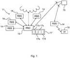
- Fig. 1illustrates schematically a WCDMA radio communication network 11 in which an arrangement according to an embodiment of the present invention is implemented.
- the radio communication network 11comprises an RNC (Radio Network Controller) 13, and a plurality of RBS's (Radio Base Stations) 14, each of which being connected to the RNC 13.
- RNCRadio Network Controller
- RBS'sRadio Base Stations
- a UE (user equipment) 16such as a mobile phone, is capable of communicating with the RNC 13 via one of the RBS's 14, e.g. the RBS 14 that is connected to the RNC 13 via the satellite 15.
- the RNC 13uses RLC (Radio Link Control) timer values during control of communication in the network, wherein the RLC timer values are parameter values set based on the RLC RTT's (Round Trip Time) for signals travelling from the RNC 13 to UE's, such as the illustrated UE 16, and back to the RNC 13.
- the RLC RTTvaries from link to link depending on the delay characteristics thereof. In particular, for satellite links the RLC RTT is much longer than for conventional terrestrial links. As a result, different RLC timer values have to be used for different communication links.
- an inventive arrangement 17 for setting and adjusting RLC timer valuesi.e. parameter values dependent on the RTT's in the radio communication network 11 and used for communication control, is provided in the radio communication network 11, preferably software implemented in the RNC 13.
- the arrangement 17comprises an estimating module 17a, a setting module 17b, a measuring module 17c, and an adjusting module 17d. While, the arrangement 17 is illustrated as being implemented in a single node, i.e. the RNC 13, the invention is not limited to such case.
- the arrangement of the inventionmay be implemented in other node or may be distributed over a plurality of nodes.
- the estimating module 17ais responsible for initially estimating a maximum value of the RTT for a given link.
- the maximum value of the RTTis determined such that it is expected to be equal to or longer than the actual RTT. That is, the maximum value of the RTT is set to correspond to a worst case delay link.
- the setting module 17bis responsible for initially setting the RLC timer value based on the initially estimated maximum value of the RTT. This conservative RLC timer value is set to ensure that the communication on the link can be established.
- the measuring module 17cis then arranged to actually measure or determine the RTT.
- the adjusting module 17dis responsible for adjusting the RLC timer value based on the measured RTT.
- the linkis initially set up with conservative RLC timer values, which are then modified to suit the actual delay characteristics of the link. Since optimum RLC timer values are closely related to the actual RLC RTT there is a need to access the actual RLC RTT in order to configure the link with optimum RLC timer values.
- the measuring module 17c and the adjusting module 17dmay operate continuously or repeatedly during communication on a link in order to dynamically adjust the RLC timer value for that link. Also for a single adjustment, repeatedly measured RTT values may be used in order to increase accuracy in the measurement.
- the measuring module 17cmay measure the RTT in a plurality of manners.
- the measuring module 17cmeasures the RTT over a link in an indirect manner.
- the initially estimated maximum value of the RTTis gradually decreased.
- the RLC timer valueis repeatedly set based on the gradually decreased maximum value.
- the repeatedly set timer valueis used continuously for control of communication over the link in question.
- a quality parameter of the communication over the linkis monitored.
- the RTTis determined based on the repeatedly set parameter and the monitored quality parameter of the communication over the link. For instance, spurious retransmissions may be monitored, and when such retransmissions occur, optimum RLC timer values have been used just before these occur.
- a polling RLC (Radio Link Control) PDU(Protocol Data Unit) is sent from the RNC 13 and a status report, ACK (Acknowledgement of reception) or NACK (Negative Acknowledgement of reception), triggered by the polling RLC PDU, is received back.
- the RLC timeris a poll timer.
- Spurious retransmissionis in this exemplary embodiment understood as additional polling RLC PDU's are sent before the transmitting entity has received and processed the status report triggered by the previously sent polling RLC PDU. This condition will result in a substantial increase in RLC retransmission indicating that the poll timer coincides with the RLC RTT.
- the measuring module 17csends a query from the RNC 13 to the UE 16. Then, a response to the query from the UE 16 is received at the RNC 13. Finally, the RTT is determined based on the time at which the query was sent and on the time at which the response was received.
- the querymay be a polling RLC (Radio Link Control) PDU (Protocol Data Unit) and the response may be a status report, ACK (Acknowledgement of reception) or NACK (Negative Acknowledgement of reception), triggered by the polling RLC PDU.
- the polling RLC PDUhas a sequence number outside the RLC window.
- RLC timer values as set and adjusted by the present inventionmay include timer RST, timer poll and timer status prohibit. However, the invention is not limited to these but may be used for a number of other RLC timer values.
- the measuring module 17cmeasures the RLC RTT by using the node synchronization measurement function in the RNC 13.
- An NSCFNode Synchronization Control frame
- RTT RNC-RBS-RNCThe RTT for a signal travelling from the RNC 13 to the RBS 14 and back to the RNC 13, here denoted RTT RNC-RBS-RNC , based on the time at which the NSCF was sent and the time at which the response NSCF was received.
- RTT RBS-UE-RBSa fixed RTT for a signal travelling from the RBS 14 to the UE 16 and back to the RBS 14, here denoted RTT RBS-UE-RBS .
- the fixed RTT for a signal travelling from the RBS 14 to the UE 16 and back to the RBS 14is preferably based on TTIDL (Transmission Time Interval Downlink), TTIUL'(Transmission Time Interval Uplink), TTI alignment DL, TTI alignment UL, jitter delay, processing delay in UE 16, and HARQ (Hybrid Automatic Repeat Request) delay according to the following formula:
- RTT RBS-UE-RBSTTIDL + TTIUL + TTI alignment DL + TTI alignment UL + Jitter delay + UE processing delay + HARQ delay wherein estimated values are :
- RTT RNC-UE-RNCthe RTT for a signal travelling from the RNC 13 to the UE 16 and back to the RNC 13, here denoted RTT RNC-UE-RNC .
- RTT RNC-UE-RNCthe RTT RNC ⁇ RBS ⁇ RNC measured by node synch + RTT RBS ⁇ UE ⁇ RBS estimated fixed
- Fig. 2is a flow scheme of a method for setting and adjusting a parameter in a radio communication network according to another embodiment of the invention.
- the parameteris used for control during communication in the radio communication network and is dependent on the RTT for a signal travelling from a radio network controller to a user equipment and back to the radio network controller.
- the methodbegins by, in a step 21, initially estimating a maximum value of the RTT, wherein the maximum value corresponds to the RTT for an expected worst case link delay.
- the parameteris, in a step 22, set based on the initially estimated maximum value of the RTT. This setting is a conservative setting ensuring functionality on the link.
- the RTTis, in a step 23, measured or determined. The RTT may be determined according to any of the approaches discussed above.
- the parameteris, in a step 24, adjusted based on the measured RTT, and the method is ended. The measured RTT is thus obviously expected to be shorter than the initially estimated maximum value of the RTT.
- the inventionhas been described in conjunction with a communication link which includes a satellite link between a radio network controller and a radio base station, the invention is not limited in this regard.
- the present inventionis applicable to a large variety of communication links with and without satellite connections.
Landscapes
- Engineering & Computer Science (AREA)
- Computer Networks & Wireless Communication (AREA)
- Signal Processing (AREA)
- Physics & Mathematics (AREA)
- Astronomy & Astrophysics (AREA)
- Aviation & Aerospace Engineering (AREA)
- General Physics & Mathematics (AREA)
- Environmental & Geological Engineering (AREA)
- Mobile Radio Communication Systems (AREA)
- Transceivers (AREA)
Description
- The invention relates to an arrangement and a method for setting and adjusting a communication control parameter in a radio communication network, which parameter is dependent on a round trip time for a signal travelling from a radio network controller to a user equipment and back to the radio network controller.
- Satellite links are characterized by rather high RLC (Radio Link Control) RTT (Round Trip Time), typically longer than 500-1000 ms, which are difficult to handle using conventional fixed RLC timer values. Such timer values are usually applied in more conventional links with a significantly lower RLC RTT, i.e. typically shorter than 100-200 ms. Therefore, the satellite links require special tables or entries in existing tables with suitable RLC timer values.
- A drawback of such approach is that the radio network controller of the radio communication network has to include rules that select which RLC timer values should be used for each link. Further, the tables may be extensive, in particular if the radio communication system supports multiple radio bearer combinations, since unique RLC timer values have to be stored for each radio bearer. In addition, each new radio bearer that is added, needs to be assigned unique RLC timer values leading to additional table updates and maintenance work.
- A further drawback is that different satellite links may have different latency characteristics and therefore a fixed set of RLC timer values for all satellite links may not be optimum, or functional problems may occur. A table based solution with fixed timer values has typically to take worst case scenarios into consideration, which leads to too conservative timer values. As a result, the throughput and the latency are adversely affected.
- Particularly, in radio communication systems having high BLER (Block error Rate), high RLC RTT deteriorates system performance, and optimum RLC timer values are thus especially important in such systems.
US 2007/0076626 A1 relates to a method and an apparatus for dynamically adjusting a data packet window size for data packet transmission in a wireless communication network. Initially, a number of data packets that are matched for a window size are transmitted to the mobile communication device, and a round trip time associated with each communication is measured. The window size for data packet transmission is then increased or decreased based on the RTT associated with each communication.JP 2005 072933 A WO 2006/104341 A2 describes a method and/or apparatus for controlling a transmission of data blocks efficiently by measuring a round trip time (RTT), and setting a control timer value according to the measured RTT. An RLC entity measures the RTT value and sets a transmission interval timer value and prohibit interval timer value using the measured RTT value.- ERICSSON: "Discussion on the L2 buffer size", 3GPP DRAFT; R2-082406 DISCUSSION ON THE L2 BUFFER SIZE, 3RD GENERATION PARTNERSHIP PROJECT (3GPP), MOBILE COMPETENCE CENTRE ; 650, ROUTE DES LUCIOLES ; F-06921 SOPHIA-ANTIPOLIS CEDEX ; FRANCE, vol. RAN WG2, no. Kansas City, USA; 20080429, 29 April 2008 (2008-04-29), XP050140096, describes a method for an analysis of the total L2 buffer size which consists of the RLC transmission and reception windows only
- The invention is defined in the independent claims, wherein an object of the present invention is therefore to provide an arrangement and a method for setting and adjusting at least one parameter in a radio communication network, which parameter is used in control of communication in the radio communication network and which is dependent on a round trip time for a signal travelling from a radio network controller to a user equipment and back to the radio network controller, e.g. a RLC timer value, by which at least some of the drawbacks as disclosed above in the background chapter are avoided or at least alleviated.
- It is a further object of the invention to provide such arrangement and method, which provide for an improved operation of the radio communication network in which they are implemented, such that low latency and high throughput can be obtained.
- It is yet a further object of the invention to provide such arrangement and method, which are fast, simple, accurate, precise, and of low cost.
- These objects, among others, are according to a first aspect of the present invention attained by an arrangement which comprises a module for initially estimating a maximum value of the round trip time, a module for initially setting the parameter based on the initially estimated maximum value of the round trip time, a module for measuring the round trip time, and a module for adjusting the parameter based on the measured round trip time. The measured round trip time is expected to be shorter than the initially estimated maximum value of the round trip time. The measuring module measures the round trip time by gradually decreasing an initially estimated maximum value of the round trip time, setting the parameter repeatedly based on the gradually decreased maximum value, using the repeatedly set parameter for control of communication in the radio communication network, monitoring a quality parameter of the communication in the radio communication network, and determining the round trip time based on the repeatedly set parameter and the monitored quality parameter of the communication in the radio communication network, where spurious retransmissions are monitored, and the value of the repeatedly set parameter to be used is a value set just before the spurious retransmissions occur.
- The invention is preferably implemented in radio communication networks which include satellite links which are characterized by longer and more unpredictable round trip times.
- An initially estimated maximum value of the round trip time, which is expected to be longer than the actual round trip time, ensures that a conservative initial parameter setting is used in order to make certain that even the satellite links with the poorest delay characteristics will function. This initial conservative parameter setting is then adjusted by the function to conform to the actual delay characteristics of the link by utilizing knowledge of the RLC RTT gained by the measuring module as described above.
- It should be noted that while the invention primarily targets satellite applications, the invention is equally applicable to fine adjust RLC timer values for conventional connections such as e.g. in ordinary terrestrial WCDMA networks. The result for both conventional and satellite links is that optimum RLC timer values will always be used thanks to the self adjusting functionality of the invention.
- In one version of the invention the measuring module measures the round trip time according to the following steps. The initially estimated maximum value of the round trip time is gradually decreased, the parameter is repeatedly set based on the gradually decreased maximum value, the repeatedly set parameter is used for control of communication in the radio communication network, a quality parameter of the communication in the radio communication network is monitored, and the round trip time is determined based on the repeatedly set parameter and the monitored quality parameter of the communication in the radio communication network.
- In another version of the invention, the measuring module measures the round trip time according to the following steps. A query is sent from the radio network controller to the user equipment, a response to the query from the user equipment is received in the radio network controller, and the round trip time is determined based on the time at which the query was sent and the time at which the response was received. If the radio communication network is a WCDMA radio communication network, the query may a polling RLC PDU (Protocol Data Unit) and the response may be a status report, ACK (Acknowledgement of reception) or NACK (Negative Acknowledgement of reception), triggered by the polling RLC PDU. Advantageously, the polling RLC PDU has a sequence number higher or lower than the RLC window.
- In yet another version of the invention, wherein the radio communication network is a WCDMA radio communication network, the measuring module measures the round trip time according to the following steps. An NSCF (Node Synchronization Control frame) is sent from the radio network controller to a radio base station connected to the radio network controller, and via which the user equipment is connected. A response NSCF to the sent NSCF is subsequently received from the radio base station at the radio network controller.
- Then, a round trip time for a signal travelling from the radio network controller to the radio base station and back to the radio network controller is determined based on the time at which the NSCF was sent and the time at which the response NSCF was received. A fixed round trip time for a signal travelling from the radio base station to the user equipment and back to the radio base station is estimated. Finally, the round trip time for a signal travelling from the radio network controller to the user equipment and back to the radio network controller is calculated as the sum of the determined round trip time for a signal travelling from the radio network controller to the radio base station and back to the radio network controller and the fixed round trip time for a signal travelling from the radio base station to the user equipment and back to the radio base station.
- Here, the fixed round trip time for a signal travelling from the radio base station to the user equipment and back to the radio base station is estimated based on TTIDL (Transmission Time Interval Downlink), TTIUL (Transmission Time Interval Uplink), TTI alignment DL, TTI alignment UL, jitter delay, processing delay in user equipment, and HARQ (Hybrid Automatic Repeat Request) delay.
- It shall be appreciated that the adjustment of the parameter may be performed on any suitable time scale, i.e. only once or repeatedly, e.g. during a communication, i.e. the measuring module measures the round trip time repeatedly and the adjusting module adjusts the parameter depending on the repeatedly measured round trip time, e.g. on the last measured round trip time or on an average of a plurality of last measured round trip times. Too high measured RTT values may be discarded. The average value is typically used to achieve higher accuracy; the more measured round trip times used, the higher accuracy is achieved.
- Further, the above-mentioned objects, among others, are according to a second aspect of the present invention attained by a method, according to which a maximum value of the round trip time is initially estimated, the parameter is next set depending on the initially estimated maximum value of the round trip time, the round trip time is measured, and finally the parameter is adjusted depending on the measured round trip time. The round trip time is measured according to the following steps: the initially estimated maximum value of the round trip time is gradually decreased, the parameter is repeatedly set based on the gradually decreased maximum value, the repeatedly set parameter is used for control of communication in the radio communication network, a quality parameter of the communication in the radio communication network is monitored, and the round trip time is determined based on the repeatedly set parameter and the monitored quality parameter of the communication in the radio communication network, where spurious retransmissions are monitored, and the value of the repeatedly set parameter to be used is a value set just before the spurious retransmissions occur. As before, the measured round trip time is expected to be shorter than the initially estimated maximum value of the round trip time. Similarly, the round trip time may be measured according to the approaches described above.
- Problems to handle data transport over satellite links due to the excessive RLC RTT associated with such connections can be addressed by the invention. In addition, satellite links with different delay characteristics can all be served by the same function.
- An important advantage of the invention is the improved latency characteristics which has a positive influence on the throughput using e.g. the TCP protocol since RLC timer values may be set more optimally then what would have been possible with a table of fixed values, since such fixed values would have been set to take care of the worst case performing links.
- It shall be appreciated that while the detailed description discloses embodiments implemented in WCDMA communication systems, the present invention is not limited to such standard, but can be implemented in various kind of communication systems using retransmission protocols such as e.g. LTE (Long Term Evolution), CDMA200, and WLAN (Wireless Local Area network) communication systems.
- The invention will now be described in more detail in relation to the enclosed drawing, in which:
Fig. 1 illustrates schematically a radio communication network in which an arrangement according to an embodiment of the present invention is implemented, andFig. 2 is a flow scheme of a method according to another embodiment of the invention.- In the following description, for purposes of explanation and not limitation, specific details are set forth such as particular architectures, interfaces, techniques, etc. in order to provide a thorough understanding of the invention. However, it will be apparent to those skilled in the art that the invention may be practiced in other embodiments that depart from these specific details. In other instances, detailed descriptions of well-known devices, circuits, and methods are omitted so as not to obscure the description of the invention with unnecessary detail.
Fig. 1 illustrates schematically a WCDMAradio communication network 11 in which an arrangement according to an embodiment of the present invention is implemented. Theradio communication network 11 comprises an RNC (Radio Network Controller) 13, and a plurality of RBS's (Radio Base Stations) 14, each of which being connected to theRNC 13. Preferably, at least oneRBS 14 is connected to theRNC 13 over asatellite 15. A UE (user equipment) 16, such as a mobile phone, is capable of communicating with theRNC 13 via one of the RBS's 14, e.g. theRBS 14 that is connected to theRNC 13 via thesatellite 15.- The
RNC 13 uses RLC (Radio Link Control) timer values during control of communication in the network, wherein the RLC timer values are parameter values set based on the RLC RTT's (Round Trip Time) for signals travelling from theRNC 13 to UE's, such as the illustratedUE 16, and back to theRNC 13. The RLC RTT varies from link to link depending on the delay characteristics thereof. In particular, for satellite links the RLC RTT is much longer than for conventional terrestrial links. As a result, different RLC timer values have to be used for different communication links. - The present invention addresses this problem in a novel manner and provides a self adjusting functionality to thereby be capable of using optimum RLC timer values for each link attuned, at each instant, to the latency characteristics of that link. To this end, an
inventive arrangement 17 for setting and adjusting RLC timer values, i.e. parameter values dependent on the RTT's in theradio communication network 11 and used for communication control, is provided in theradio communication network 11, preferably software implemented in theRNC 13. Thearrangement 17 comprises anestimating module 17a, asetting module 17b, a measuringmodule 17c, and anadjusting module 17d. While, thearrangement 17 is illustrated as being implemented in a single node, i.e. theRNC 13, the invention is not limited to such case. The arrangement of the invention may be implemented in other node or may be distributed over a plurality of nodes. - The
estimating module 17a is responsible for initially estimating a maximum value of the RTT for a given link. The maximum value of the RTT is determined such that it is expected to be equal to or longer than the actual RTT. That is, the maximum value of the RTT is set to correspond to a worst case delay link. Thesetting module 17b is responsible for initially setting the RLC timer value based on the initially estimated maximum value of the RTT. This conservative RLC timer value is set to ensure that the communication on the link can be established. The measuringmodule 17c is then arranged to actually measure or determine the RTT. Finally, the adjustingmodule 17d is responsible for adjusting the RLC timer value based on the measured RTT. In other words, the link is initially set up with conservative RLC timer values, which are then modified to suit the actual delay characteristics of the link. Since optimum RLC timer values are closely related to the actual RLC RTT there is a need to access the actual RLC RTT in order to configure the link with optimum RLC timer values. - It shall be appreciated that the measuring
module 17c and theadjusting module 17d may operate continuously or repeatedly during communication on a link in order to dynamically adjust the RLC timer value for that link. Also for a single adjustment, repeatedly measured RTT values may be used in order to increase accuracy in the measurement. - The measuring
module 17c may measure the RTT in a plurality of manners. - In a first embodiment of the invention, the measuring
module 17c measures the RTT over a link in an indirect manner. The initially estimated maximum value of the RTT is gradually decreased. The RLC timer value is repeatedly set based on the gradually decreased maximum value. The repeatedly set timer value is used continuously for control of communication over the link in question. A quality parameter of the communication over the link is monitored. Finally, the RTT is determined based on the repeatedly set parameter and the monitored quality parameter of the communication over the link. For instance, spurious retransmissions may be monitored, and when such retransmissions occur, optimum RLC timer values have been used just before these occur. - In an exemplary embodiment a polling RLC (Radio Link Control) PDU (Protocol Data Unit) is sent from the
RNC 13 and a status report, ACK (Acknowledgement of reception) or NACK (Negative Acknowledgement of reception), triggered by the polling RLC PDU, is received back. The RLC timer is a poll timer. Spurious retransmission is in this exemplary embodiment understood as additional polling RLC PDU's are sent before the transmitting entity has received and processed the status report triggered by the previously sent polling RLC PDU. This condition will result in a substantial increase in RLC retransmission indicating that the poll timer coincides with the RLC RTT. - In another embodiment of the invention, the measuring
module 17c sends a query from theRNC 13 to theUE 16. Then, a response to the query from theUE 16 is received at theRNC 13. Finally, the RTT is determined based on the time at which the query was sent and on the time at which the response was received. Implementing this embodiment in a WCDMA radio communication network, the query may be a polling RLC (Radio Link Control) PDU (Protocol Data Unit) and the response may be a status report, ACK (Acknowledgement of reception) or NACK (Negative Acknowledgement of reception), triggered by the polling RLC PDU. Preferably, the polling RLC PDU has a sequence number outside the RLC window. In such case, however, a so-called RLC reset, which is typically performed by theRNC 13 in response to receiving the status report, is prevented from being made. An advantage with this approach is that it can be used even though the connection activity is such that it is difficult to determine which PDU initiates which status report. - RLC timer values as set and adjusted by the present invention may include timer RST, timer poll and timer status prohibit. However, the invention is not limited to these but may be used for a number of other RLC timer values.
- In yet another embodiment of the invention, wherein the radio communication network is a WCDMA network, the measuring
module 17c measures the RLC RTT by using the node synchronization measurement function in theRNC 13. An NSCF (Node Synchronization Control frame) is sent from theRNC 13 to anRBS 14 connected to theRNC 13, and via which theUE 16 is connected. A response NSCF to the sent NSCF is received from theRBS 14 at theRNC 13. The RTT for a signal travelling from theRNC 13 to theRBS 14 and back to theRNC 13, here denoted RTTRNC-RBS-RNC, based on the time at which the NSCF was sent and the time at which the response NSCF was received. - More in detail, the RTTRNC-RBS-RNC as measured by the node synchronization is

- T1 - sending time stamp of the control frame in the RNC
- T2 - reception time stamp of the control frame in the RBS
- T3 - sending time stamp of the control frame in the RBS
- T4 - reception time stamp of the control frame in the RNC
- Next, a fixed RTT for a signal travelling from the
RBS 14 to theUE 16 and back to theRBS 14, here denoted RTTRBS-UE-RBS, is estimated. The fixed RTT for a signal travelling from theRBS 14 to theUE 16 and back to theRBS 14 is preferably based on TTIDL (Transmission Time Interval Downlink), TTIUL'(Transmission Time Interval Uplink), TTI alignment DL, TTI alignment UL, jitter delay, processing delay inUE 16, and HARQ (Hybrid Automatic Repeat Request) delay according to the following formula:
- TTIDL 2-40 ms depending on radio bearer type
- TTIUL 2-40 ms depending on radio bearer type
- TTI alignment DL 2-40 ms depending on radio bearer type
- TTI alignment UL 2-40 ms depending on radio bearer type Jitter delay 50-100 ms
- UE processing delay 50-100 ms
- HARQ delay 10-40 ms
- Finally, the RTT for a signal travelling from the
RNC 13 to theUE 16 and back to theRNC 13, here denoted RTTRNC-UE-RNC, is calculated as the sum of the determined RTT for a signal travelling from theRNC 13 to theRBS 14 and back to theRNC 13 and the estimated fixed round trip time for a signal travelling from theRBS 14 to theUE 16 and back to theRBS 14, i.e.
Fig. 2 is a flow scheme of a method for setting and adjusting a parameter in a radio communication network according to another embodiment of the invention. The parameter is used for control during communication in the radio communication network and is dependent on the RTT for a signal travelling from a radio network controller to a user equipment and back to the radio network controller. The method begins by, in astep 21, initially estimating a maximum value of the RTT, wherein the maximum value corresponds to the RTT for an expected worst case link delay. Next, the parameter is, in astep 22, set based on the initially estimated maximum value of the RTT. This setting is a conservative setting ensuring functionality on the link. Next, the RTT is, in astep 23, measured or determined. The RTT may be determined according to any of the approaches discussed above. Finally, the parameter is, in astep 24, adjusted based on the measured RTT, and the method is ended. The measured RTT is thus obviously expected to be shorter than the initially estimated maximum value of the RTT.- While the invention has been described in connection with what is presently considered to be most practical and preferred embodiments, it is to be understood that the invention is not to be limited to the disclosed embodiments, but on the contrary, is intended to cover various modifications and equivalent arrangements.
- Therefore the invention is only to be limited by the following claims.
- In particular, while the invention has been described in conjunction with a communication link which includes a satellite link between a radio network controller and a radio base station, the invention is not limited in this regard. The present invention is applicable to a large variety of communication links with and without satellite connections.


Claims (6)
- An arrangement (17) for setting and adjusting at least one parameter in a radio communication network (11), said parameter being a radio link control (RLC) timer value used in control of communication in said radio communication network and being set based on a round trip time for a signal travelling from a radio network controller (13) to a user equipment (16) and back to said radio network controller on a given link, the arrangement comprising:- an estimating module (17a) provided for initially estimating a maximum value of the round trip time for the given link, wherein the initially estimated maximum value of the round trip time corresponds to an expected worst case delay on the given link;- a setting module (17b) provided for initially setting a value of said parameter to a conservative value based on the initially estimated maximum value of the round trip time;- a measuring module (17c) provided for measuring the round trip time for the given link;- an adjusting module (17d) provided for adjusting said value of said parameter depending on the measured round trip time, wherein the adjusting module (17d) is provided for adjusting said value of said parameter by modifying said value of said parameter to conform to actual delay characteristics of the given link, and wherein the measured round trip time is expected to be shorter than the initially estimated maximum value of the round trip time,wherein said measuring module is provided for measuring the round trip time by means of:(i) gradually decreasing the initially estimated maximum value of the round trip time,(ii) repeatedly setting said parameter depending on the gradually decreased maximum value,(iii) using said repeatedly set parameter for control of communication in said radio communication network;(iv) monitoring a quality parameter of the communication in said radio communication network; and(v) determining the round trip time based on said repeatedly set parameter and the monitored quality parameter of the communication in said radio communication network, wherein spurious retransmissions as being the quality parameter are monitored, and the value of the repeatedly set parameter to be used is a value set just before the spurious retransmissions occur.
- The arrangement of claim 1 wherein said measuring module is provided for measuring the round trip time repeatedly during a communication between said radio network controller and said user equipment; and said adjusting module is provided for adjusting said parameter depending on the repeatedly measured round trip time.
- The arrangement of any of claims 1-2 provided for setting and adjusting said parameter in said radio communication network, wherein the given link is a satellite link (15) between said radio network controller and said user equipment, preferably between said radio communication network and a radio base station (14) connected to the radio network controller, and via which said user equipment is connected.
- A radio network controller (13) comprising the arrangement of any of claims 1-3.
- A method for setting and adjusting at least one parameter in a radio communication network (11), said parameter being a radio link control (RLC) timer value used for control in communication in said radio communication network and being set based on a round trip time for a signal travelling from a radio network controller (13) to a user equipment (16) and back to said radio network controller on a given link, the method comprising the steps of:- initially estimating (21) a maximum value of the round trip time for the given link, wherein the initially estimated maximum value of the round trip time corresponds to an expected worst case delay on the given link;- initially setting (22) a value of said parameter to a conservative value based on the initially estimated maximum value of the round trip time;- measuring (23) the round trip time for the given link;- adjusting (24) said value of said parameter depending on the measured round trip time, wherein the adjusting comprises modifying said value of said parameter to conform to actual delay characteristics of the given link, and wherein the measured round trip time is expected to be shorter than the initially estimated maximum value of the round trip time,wherein said round trip time is measured by means of:(i) gradually decreasing the initially estimated maximum value of the round trip time,(ii) repeatedly setting said parameter depending on the gradually decreased maximum value of the round trip time,(iii) using said repeatedly set parameter for control of communication in said radio communication network;(iv) monitoring a quality parameter of the communication in said radio communication network; and(v) determining the round trip time based on the repeatedly set parameter and the monitored quality parameter of the communication in said radio communication network, wherein spurious retransmissions as being the quality parameter are monitored, and the value of the repeatedly set parameter to be used is a value set just before the spurious retransmissions occur.
- The method of claim 5, wherein the round trip time is measured repeatedly during a communication between said radio network controller (13) and said user equipment (16); and
adjusting said parameter depending on the repeatedly measured round trip time.
Applications Claiming Priority (1)
| Application Number | Priority Date | Filing Date | Title |
|---|---|---|---|
| PCT/SE2010/050462WO2011136705A1 (en) | 2010-04-26 | 2010-04-26 | Method for setting and adjusting a parameter dependent on a round trip time |
Publications (3)
| Publication Number | Publication Date |
|---|---|
| EP2564557A1 EP2564557A1 (en) | 2013-03-06 |
| EP2564557A4 EP2564557A4 (en) | 2014-01-22 |
| EP2564557B1true EP2564557B1 (en) | 2018-12-12 |
Family
ID=44861767
Family Applications (1)
| Application Number | Title | Priority Date | Filing Date |
|---|---|---|---|
| EP10850846.6ANot-in-forceEP2564557B1 (en) | 2010-04-26 | 2010-04-26 | Method for setting and adjusting a parameter dependent on a round trip time |
Country Status (3)
| Country | Link |
|---|---|
| US (1) | US9019854B2 (en) |
| EP (1) | EP2564557B1 (en) |
| WO (1) | WO2011136705A1 (en) |
Families Citing this family (14)
| Publication number | Priority date | Publication date | Assignee | Title |
|---|---|---|---|---|
| CN103378947A (en)* | 2012-04-28 | 2013-10-30 | 华为技术有限公司 | Method and device for uplink MIMO transmission |
| US9125168B2 (en) | 2013-01-23 | 2015-09-01 | Intel Corporation | Polled time-of-flight response |
| KR102141854B1 (en)* | 2014-02-21 | 2020-08-06 | 삼성전자주식회사 | Apparatus and method for controlling push message transmission |
| US10039149B2 (en)* | 2014-03-19 | 2018-07-31 | Ntt Docomo, Inc. | User equipment and uplink data transmission method |
| CN104301945B (en)* | 2014-09-24 | 2018-05-11 | 上海华为技术有限公司 | A kind of timer duration method of adjustment and base station |
| MX367593B (en)* | 2015-06-02 | 2019-08-28 | Ericsson Telefon Ab L M | Network node and method therein for handover in wireless communication network. |
| JP6545827B2 (en) | 2015-06-02 | 2019-07-17 | テレフオンアクチーボラゲット エルエム エリクソン(パブル) | Communication device for handover in a wireless communication network and method thereof |
| US10148538B2 (en)* | 2016-01-21 | 2018-12-04 | Fujitsu Limited | Distributed controllers |
| US10389513B2 (en)* | 2017-01-26 | 2019-08-20 | Hewlett Packard Enterprise Development Lp | Dynamic adjustment of wait time values |
| US11362921B2 (en) | 2017-12-19 | 2022-06-14 | Qualcomm Incorporated | Systems and methods for multiple round trip time (RTT) estimation in wireless networks |
| KR102665409B1 (en) | 2018-10-16 | 2024-05-10 | 삼성전자주식회사 | Method and apparatus for splitting data in multi-connectivity |
| US11856451B2 (en) | 2020-03-02 | 2023-12-26 | Qualcomm Incorporated | Avoiding packet data convergence protocol holes for bearer in dual connectivity mode across multiple radio access technologies |
| CN111757460B (en)* | 2020-06-05 | 2022-03-04 | 西安空间无线电技术研究所 | A Time Synchronization Method of Satellite Communication Network Based on Centerless TDMA |
| US11811671B2 (en)* | 2021-07-02 | 2023-11-07 | Qualcomm Incorporated | Techniques for reducing a feedback time for communications over multiple wireless connections |
Family Cites Families (37)
| Publication number | Priority date | Publication date | Assignee | Title |
|---|---|---|---|---|
| EP1077559A1 (en)* | 1999-08-17 | 2001-02-21 | Telefonaktiebolaget Lm Ericsson | Method and device for determining a time-parameter |
| US6608818B1 (en)* | 1999-11-10 | 2003-08-19 | Qualcomm Incorporated | Radio link protocol enhancements to reduce setup time for data calls |
| US6681099B1 (en)* | 2000-05-15 | 2004-01-20 | Nokia Networks Oy | Method to calculate true round trip propagation delay and user equipment location in WCDMA/UTRAN |
| US7254401B2 (en)* | 2000-12-19 | 2007-08-07 | Nokia Corporation | Network-based method and system for determining a location of user equipment in CDMA networks |
| US7099273B2 (en)* | 2001-04-12 | 2006-08-29 | Bytemobile, Inc. | Data transport acceleration and management within a network communication system |
| US20020167948A1 (en)* | 2001-05-09 | 2002-11-14 | Dayong Chen | Communications methods, apparatus, computer program products and data structures using segment sequence numbers |
| TW527804B (en)* | 2001-05-25 | 2003-04-11 | Accton Technology Corp | Method and apparatus for bandwidth management of TCP traffic employing post-acknowledgement control |
| GB2372172B (en)* | 2001-05-31 | 2002-12-24 | Ericsson Telefon Ab L M | Congestion handling in a packet data network |
| SE0102775D0 (en)* | 2001-08-17 | 2001-08-17 | Ericsson Telefon Ab L M | Method and system of retransmission |
| US7352715B2 (en)* | 2001-11-30 | 2008-04-01 | Cellnet Innovations, Inc. | Time synchronization using dynamic thresholds |
| AU2002216136A1 (en)* | 2001-12-04 | 2003-06-17 | Nokia Corporation | Method and system for dispatching multiple tcp packets from communication systems |
| ATE349828T1 (en)* | 2002-08-13 | 2007-01-15 | Matsushita Electric Industrial Co Ltd | HYBRID AUTOMATIC REPOST REQUEST PROTOCOL |
| US7225266B2 (en)* | 2002-12-20 | 2007-05-29 | Nokia Corporation | Adaptive delayed ACK switching for TCP applications |
| US7489691B2 (en)* | 2002-12-23 | 2009-02-10 | Nokia Corporation | Scheduling retransmission in access networks |
| GB2403378B (en)* | 2003-06-27 | 2007-05-30 | Ipwireless Inc | Method and arrangement for TCP flow control |
| JP2005072933A (en)* | 2003-08-25 | 2005-03-17 | Renesas Technology Corp | Network device |
| EP1665586A1 (en)* | 2003-09-11 | 2006-06-07 | Telefonaktiebolaget LM Ericsson (publ) | Transmission time interval alignment in wcdma systems |
| US7346680B2 (en)* | 2003-09-22 | 2008-03-18 | Intel Corporation | Speculative prefetch of a protocol control block from an external memory unit |
| US8125910B2 (en)* | 2004-06-25 | 2012-02-28 | Nec Corporation | Communication system |
| US7423977B1 (en)* | 2004-08-23 | 2008-09-09 | Foundry Networks Inc. | Smoothing algorithm for round trip time (RTT) measurements |
| US7525908B2 (en)* | 2004-09-24 | 2009-04-28 | M-Stack Limited | Data unit management in communications |
| CN101133599B (en)* | 2004-12-24 | 2011-04-20 | 阿斯帕拉公司 | Method and system for bulk data transfer |
| US8214707B2 (en)* | 2007-06-26 | 2012-07-03 | Aspera, Inc. | Method and system for reliable data transfer |
| KR101141645B1 (en) | 2005-03-29 | 2012-05-17 | 엘지전자 주식회사 | Method for Controlling Transmission of Data Block |
| US20080232405A1 (en)* | 2005-08-25 | 2008-09-25 | Nxp B.V. | Method and Circuit for Calculating a Timeout Parameter in a Communication Session |
| EP1929687B1 (en)* | 2005-09-30 | 2011-05-25 | Research In Motion Limited | Methods and apparatus for dynamically adjusting a data packet window size for data packet transmission in a wireless communication network |
| US20070091922A1 (en)* | 2005-10-21 | 2007-04-26 | Steven Elliot | Method and apparatus for adaptive bandwidth control with a bandwidth guarantee |
| US7558271B2 (en)* | 2005-10-21 | 2009-07-07 | International Business Machines Corporation | Method and apparatus for adaptive bandwidth control with defined priorities for different networks |
| FR2898759B1 (en)* | 2006-03-14 | 2008-05-16 | Cell & Sat Soc Par Actions Sim | METHOD OF OPTIMIZING THE RESOURCE ALLOCATION IN A CELLULAR NETWORK USING A SHARED RADIO TRANSMISSION LINK, NETWORK AND CORRESPONDING NETWORK ADAPTERS. |
| EP2074732A4 (en)* | 2006-10-27 | 2012-05-09 | Ericsson Telefon Ab L M | Method and arrangement for efficiently utilizing radio resources in a communication network |
| DE602008006242D1 (en)* | 2007-11-01 | 2011-05-26 | Ericsson Telefon Ab L M | LIMITING THE RLC WINDOW SIZE IN A HSDPA FLOW CONTROL |
| JP5070239B2 (en)* | 2008-04-15 | 2012-11-07 | 創新音▲速▼股▲ふん▼有限公司 | Method and communication apparatus for improving TTI bundling transmission |
| US20110044199A1 (en) | 2008-04-25 | 2011-02-24 | Muhammad Kazmi | Method for Determining the Round Trip Time |
| US20100226384A1 (en)* | 2009-03-09 | 2010-09-09 | Prabhakar Balaji S | Method for reliable transport in data networks |
| US8160015B2 (en)* | 2009-10-27 | 2012-04-17 | Qualcomm Incorporated | Systems and methods for measuring and reducing latency of radio link flows |
| US20120054362A1 (en)* | 2010-08-31 | 2012-03-01 | Canon Kabushiki Kaisha | Mechanism for autotuning mass data transfer from a sender to a receiver over parallel connections |
| US8923863B2 (en)* | 2011-12-19 | 2014-12-30 | Cisco Technology, Inc. | Maintaining signaling reduction mode in communication networks |
- 2010
- 2010-04-26EPEP10850846.6Apatent/EP2564557B1/ennot_activeNot-in-force
- 2010-04-26WOPCT/SE2010/050462patent/WO2011136705A1/enactiveApplication Filing
- 2010-04-26USUS13/642,645patent/US9019854B2/ennot_activeExpired - Fee Related
Also Published As
| Publication number | Publication date |
|---|---|
| EP2564557A4 (en) | 2014-01-22 |
| EP2564557A1 (en) | 2013-03-06 |
| US9019854B2 (en) | 2015-04-28 |
| WO2011136705A1 (en) | 2011-11-03 |
| US20130039208A1 (en) | 2013-02-14 |
Similar Documents
| Publication | Publication Date | Title |
|---|---|---|
| EP2564557B1 (en) | Method for setting and adjusting a parameter dependent on a round trip time | |
| US10397826B2 (en) | Method and arrangement in a wireless communication network | |
| US12250134B2 (en) | Method and apparatus for splitting data in multi-connectivity | |
| US20190223256A1 (en) | Data transmission method, network device, and terminal device | |
| JP3968317B2 (en) | Wireless base station equipment | |
| JP6685295B2 (en) | base station | |
| CN115734349A (en) | Systems and methods for reducing transmission data collisions for dual-user dual-active devices | |
| HK40074087A (en) | Method and arrangement in a wireless communication network for requesting a status report | |
| HK40074087B (en) | Method and arrangement in a wireless communication network for requesting a status report | |
| HK40034913A (en) | Method and arrangement in a wireless communication network | |
| HK40034913B (en) | Method and arrangement in a wireless communication network | |
| CN103188036B (en) | Adjust method and the communicator of transmission control protocol data transmission | |
| CN106658596A (en) | Data packet processing method, data packet processing device, and communication system |
Legal Events
| Date | Code | Title | Description |
|---|---|---|---|
| PUAI | Public reference made under article 153(3) epc to a published international application that has entered the european phase | Free format text:ORIGINAL CODE: 0009012 | |
| 17P | Request for examination filed | Effective date:20121015 | |
| AK | Designated contracting states | Kind code of ref document:A1 Designated state(s):AT BE BG CH CY CZ DE DK EE ES FI FR GB GR HR HU IE IS IT LI LT LU LV MC MK MT NL NO PL PT RO SE SI SK SM TR | |
| DAX | Request for extension of the european patent (deleted) | ||
| A4 | Supplementary search report drawn up and despatched | Effective date:20140102 | |
| RIC1 | Information provided on ipc code assigned before grant | Ipc:H04L 12/26 20060101AFI20131217BHEP Ipc:H04W 24/00 20090101ALI20131217BHEP Ipc:H04L 12/24 20060101ALI20131217BHEP Ipc:H04L 12/801 20130101ALI20131217BHEP | |
| STAA | Information on the status of an ep patent application or granted ep patent | Free format text:STATUS: EXAMINATION IS IN PROGRESS | |
| 17Q | First examination report despatched | Effective date:20170201 | |
| GRAP | Despatch of communication of intention to grant a patent | Free format text:ORIGINAL CODE: EPIDOSNIGR1 | |
| STAA | Information on the status of an ep patent application or granted ep patent | Free format text:STATUS: GRANT OF PATENT IS INTENDED | |
| RIC1 | Information provided on ipc code assigned before grant | Ipc:H04B 7/185 20060101ALI20180828BHEP Ipc:H04L 12/26 20060101AFI20180828BHEP Ipc:H04W 24/02 20090101ALI20180828BHEP Ipc:H04W 56/00 20090101ALI20180828BHEP Ipc:H04L 12/24 20060101ALI20180828BHEP | |
| INTG | Intention to grant announced | Effective date:20181002 | |
| GRAS | Grant fee paid | Free format text:ORIGINAL CODE: EPIDOSNIGR3 | |
| GRAA | (expected) grant | Free format text:ORIGINAL CODE: 0009210 | |
| STAA | Information on the status of an ep patent application or granted ep patent | Free format text:STATUS: THE PATENT HAS BEEN GRANTED | |
| AK | Designated contracting states | Kind code of ref document:B1 Designated state(s):AT BE BG CH CY CZ DE DK EE ES FI FR GB GR HR HU IE IS IT LI LT LU LV MC MK MT NL NO PL PT RO SE SI SK SM TR | |
| REG | Reference to a national code | Ref country code:GB Ref legal event code:FG4D | |
| REG | Reference to a national code | Ref country code:CH Ref legal event code:EP | |
| REG | Reference to a national code | Ref country code:AT Ref legal event code:REF Ref document number:1077440 Country of ref document:AT Kind code of ref document:T Effective date:20181215 | |
| REG | Reference to a national code | Ref country code:DE Ref legal event code:R096 Ref document number:602010055845 Country of ref document:DE | |
| REG | Reference to a national code | Ref country code:IE Ref legal event code:FG4D | |
| REG | Reference to a national code | Ref country code:NL Ref legal event code:MP Effective date:20181212 | |
| REG | Reference to a national code | Ref country code:LT Ref legal event code:MG4D | |
| PG25 | Lapsed in a contracting state [announced via postgrant information from national office to epo] | Ref country code:LV Free format text:LAPSE BECAUSE OF FAILURE TO SUBMIT A TRANSLATION OF THE DESCRIPTION OR TO PAY THE FEE WITHIN THE PRESCRIBED TIME-LIMIT Effective date:20181212 Ref country code:NO Free format text:LAPSE BECAUSE OF FAILURE TO SUBMIT A TRANSLATION OF THE DESCRIPTION OR TO PAY THE FEE WITHIN THE PRESCRIBED TIME-LIMIT Effective date:20190312 Ref country code:HR Free format text:LAPSE BECAUSE OF FAILURE TO SUBMIT A TRANSLATION OF THE DESCRIPTION OR TO PAY THE FEE WITHIN THE PRESCRIBED TIME-LIMIT Effective date:20181212 Ref country code:BG Free format text:LAPSE BECAUSE OF FAILURE TO SUBMIT A TRANSLATION OF THE DESCRIPTION OR TO PAY THE FEE WITHIN THE PRESCRIBED TIME-LIMIT Effective date:20190312 Ref country code:LT Free format text:LAPSE BECAUSE OF FAILURE TO SUBMIT A TRANSLATION OF THE DESCRIPTION OR TO PAY THE FEE WITHIN THE PRESCRIBED TIME-LIMIT Effective date:20181212 Ref country code:ES Free format text:LAPSE BECAUSE OF FAILURE TO SUBMIT A TRANSLATION OF THE DESCRIPTION OR TO PAY THE FEE WITHIN THE PRESCRIBED TIME-LIMIT Effective date:20181212 Ref country code:FI Free format text:LAPSE BECAUSE OF FAILURE TO SUBMIT A TRANSLATION OF THE DESCRIPTION OR TO PAY THE FEE WITHIN THE PRESCRIBED TIME-LIMIT Effective date:20181212 | |
| REG | Reference to a national code | Ref country code:AT Ref legal event code:MK05 Ref document number:1077440 Country of ref document:AT Kind code of ref document:T Effective date:20181212 | |
| PG25 | Lapsed in a contracting state [announced via postgrant information from national office to epo] | Ref country code:GR Free format text:LAPSE BECAUSE OF FAILURE TO SUBMIT A TRANSLATION OF THE DESCRIPTION OR TO PAY THE FEE WITHIN THE PRESCRIBED TIME-LIMIT Effective date:20190313 Ref country code:SE Free format text:LAPSE BECAUSE OF FAILURE TO SUBMIT A TRANSLATION OF THE DESCRIPTION OR TO PAY THE FEE WITHIN THE PRESCRIBED TIME-LIMIT Effective date:20181212 | |
| PG25 | Lapsed in a contracting state [announced via postgrant information from national office to epo] | Ref country code:NL Free format text:LAPSE BECAUSE OF FAILURE TO SUBMIT A TRANSLATION OF THE DESCRIPTION OR TO PAY THE FEE WITHIN THE PRESCRIBED TIME-LIMIT Effective date:20181212 | |
| PG25 | Lapsed in a contracting state [announced via postgrant information from national office to epo] | Ref country code:PL Free format text:LAPSE BECAUSE OF FAILURE TO SUBMIT A TRANSLATION OF THE DESCRIPTION OR TO PAY THE FEE WITHIN THE PRESCRIBED TIME-LIMIT Effective date:20181212 Ref country code:CZ Free format text:LAPSE BECAUSE OF FAILURE TO SUBMIT A TRANSLATION OF THE DESCRIPTION OR TO PAY THE FEE WITHIN THE PRESCRIBED TIME-LIMIT Effective date:20181212 Ref country code:PT Free format text:LAPSE BECAUSE OF FAILURE TO SUBMIT A TRANSLATION OF THE DESCRIPTION OR TO PAY THE FEE WITHIN THE PRESCRIBED TIME-LIMIT Effective date:20190412 Ref country code:IT Free format text:LAPSE BECAUSE OF FAILURE TO SUBMIT A TRANSLATION OF THE DESCRIPTION OR TO PAY THE FEE WITHIN THE PRESCRIBED TIME-LIMIT Effective date:20181212 | |
| PG25 | Lapsed in a contracting state [announced via postgrant information from national office to epo] | Ref country code:RO Free format text:LAPSE BECAUSE OF FAILURE TO SUBMIT A TRANSLATION OF THE DESCRIPTION OR TO PAY THE FEE WITHIN THE PRESCRIBED TIME-LIMIT Effective date:20181212 Ref country code:IS Free format text:LAPSE BECAUSE OF FAILURE TO SUBMIT A TRANSLATION OF THE DESCRIPTION OR TO PAY THE FEE WITHIN THE PRESCRIBED TIME-LIMIT Effective date:20190412 Ref country code:EE Free format text:LAPSE BECAUSE OF FAILURE TO SUBMIT A TRANSLATION OF THE DESCRIPTION OR TO PAY THE FEE WITHIN THE PRESCRIBED TIME-LIMIT Effective date:20181212 Ref country code:SM Free format text:LAPSE BECAUSE OF FAILURE TO SUBMIT A TRANSLATION OF THE DESCRIPTION OR TO PAY THE FEE WITHIN THE PRESCRIBED TIME-LIMIT Effective date:20181212 Ref country code:SK Free format text:LAPSE BECAUSE OF FAILURE TO SUBMIT A TRANSLATION OF THE DESCRIPTION OR TO PAY THE FEE WITHIN THE PRESCRIBED TIME-LIMIT Effective date:20181212 | |
| REG | Reference to a national code | Ref country code:DE Ref legal event code:R097 Ref document number:602010055845 Country of ref document:DE | |
| PLBE | No opposition filed within time limit | Free format text:ORIGINAL CODE: 0009261 | |
| STAA | Information on the status of an ep patent application or granted ep patent | Free format text:STATUS: NO OPPOSITION FILED WITHIN TIME LIMIT | |
| PG25 | Lapsed in a contracting state [announced via postgrant information from national office to epo] | Ref country code:SI Free format text:LAPSE BECAUSE OF FAILURE TO SUBMIT A TRANSLATION OF THE DESCRIPTION OR TO PAY THE FEE WITHIN THE PRESCRIBED TIME-LIMIT Effective date:20181212 Ref country code:AT Free format text:LAPSE BECAUSE OF FAILURE TO SUBMIT A TRANSLATION OF THE DESCRIPTION OR TO PAY THE FEE WITHIN THE PRESCRIBED TIME-LIMIT Effective date:20181212 Ref country code:DK Free format text:LAPSE BECAUSE OF FAILURE TO SUBMIT A TRANSLATION OF THE DESCRIPTION OR TO PAY THE FEE WITHIN THE PRESCRIBED TIME-LIMIT Effective date:20181212 | |
| 26N | No opposition filed | Effective date:20190913 | |
| REG | Reference to a national code | Ref country code:CH Ref legal event code:PL | |
| REG | Reference to a national code | Ref country code:BE Ref legal event code:MM Effective date:20190430 | |
| PG25 | Lapsed in a contracting state [announced via postgrant information from national office to epo] | Ref country code:LU Free format text:LAPSE BECAUSE OF NON-PAYMENT OF DUE FEES Effective date:20190426 Ref country code:MC Free format text:LAPSE BECAUSE OF FAILURE TO SUBMIT A TRANSLATION OF THE DESCRIPTION OR TO PAY THE FEE WITHIN THE PRESCRIBED TIME-LIMIT Effective date:20181212 | |
| PG25 | Lapsed in a contracting state [announced via postgrant information from national office to epo] | Ref country code:LI Free format text:LAPSE BECAUSE OF NON-PAYMENT OF DUE FEES Effective date:20190430 Ref country code:CH Free format text:LAPSE BECAUSE OF NON-PAYMENT OF DUE FEES Effective date:20190430 | |
| PG25 | Lapsed in a contracting state [announced via postgrant information from national office to epo] | Ref country code:BE Free format text:LAPSE BECAUSE OF NON-PAYMENT OF DUE FEES Effective date:20190430 Ref country code:FR Free format text:LAPSE BECAUSE OF NON-PAYMENT OF DUE FEES Effective date:20190430 | |
| PG25 | Lapsed in a contracting state [announced via postgrant information from national office to epo] | Ref country code:TR Free format text:LAPSE BECAUSE OF FAILURE TO SUBMIT A TRANSLATION OF THE DESCRIPTION OR TO PAY THE FEE WITHIN THE PRESCRIBED TIME-LIMIT Effective date:20181212 | |
| PG25 | Lapsed in a contracting state [announced via postgrant information from national office to epo] | Ref country code:IE Free format text:LAPSE BECAUSE OF NON-PAYMENT OF DUE FEES Effective date:20190426 | |
| PGFP | Annual fee paid to national office [announced via postgrant information from national office to epo] | Ref country code:DE Payment date:20200429 Year of fee payment:11 | |
| PGFP | Annual fee paid to national office [announced via postgrant information from national office to epo] | Ref country code:GB Payment date:20200427 Year of fee payment:11 | |
| PG25 | Lapsed in a contracting state [announced via postgrant information from national office to epo] | Ref country code:CY Free format text:LAPSE BECAUSE OF FAILURE TO SUBMIT A TRANSLATION OF THE DESCRIPTION OR TO PAY THE FEE WITHIN THE PRESCRIBED TIME-LIMIT Effective date:20181212 | |
| PG25 | Lapsed in a contracting state [announced via postgrant information from national office to epo] | Ref country code:HU Free format text:LAPSE BECAUSE OF FAILURE TO SUBMIT A TRANSLATION OF THE DESCRIPTION OR TO PAY THE FEE WITHIN THE PRESCRIBED TIME-LIMIT; INVALID AB INITIO Effective date:20100426 Ref country code:MT Free format text:LAPSE BECAUSE OF FAILURE TO SUBMIT A TRANSLATION OF THE DESCRIPTION OR TO PAY THE FEE WITHIN THE PRESCRIBED TIME-LIMIT Effective date:20181212 | |
| REG | Reference to a national code | Ref country code:DE Ref legal event code:R119 Ref document number:602010055845 Country of ref document:DE | |
| REG | Reference to a national code | Ref country code:DE Ref legal event code:R079 Ref document number:602010055845 Country of ref document:DE Free format text:PREVIOUS MAIN CLASS: H04L0012260000 Ipc:H04L0043000000 | |
| GBPC | Gb: european patent ceased through non-payment of renewal fee | Effective date:20210426 | |
| PG25 | Lapsed in a contracting state [announced via postgrant information from national office to epo] | Ref country code:DE Free format text:LAPSE BECAUSE OF NON-PAYMENT OF DUE FEES Effective date:20211103 Ref country code:GB Free format text:LAPSE BECAUSE OF NON-PAYMENT OF DUE FEES Effective date:20210426 | |
| PG25 | Lapsed in a contracting state [announced via postgrant information from national office to epo] | Ref country code:MK Free format text:LAPSE BECAUSE OF FAILURE TO SUBMIT A TRANSLATION OF THE DESCRIPTION OR TO PAY THE FEE WITHIN THE PRESCRIBED TIME-LIMIT Effective date:20181212 |