EP2564466B1 - COMPACT RADIANT ELEMENT WITH RESONANT CAVITES - Google Patents
COMPACT RADIANT ELEMENT WITH RESONANT CAVITESDownload PDFInfo
- Publication number
- EP2564466B1 EP2564466B1EP11717197.5AEP11717197AEP2564466B1EP 2564466 B1EP2564466 B1EP 2564466B1EP 11717197 AEP11717197 AEP 11717197AEP 2564466 B1EP2564466 B1EP 2564466B1
- Authority
- EP
- European Patent Office
- Prior art keywords
- radiating element
- cavity
- polarising
- lower cavity
- radome
- Prior art date
- Legal status (The legal status is an assumption and is not a legal conclusion. Google has not performed a legal analysis and makes no representation as to the accuracy of the status listed.)
- Active
Links
Images


Classifications
- H—ELECTRICITY
- H01—ELECTRIC ELEMENTS
- H01Q—ANTENNAS, i.e. RADIO AERIALS
- H01Q13/00—Waveguide horns or mouths; Slot antennas; Leaky-waveguide antennas; Equivalent structures causing radiation along the transmission path of a guided wave
- H—ELECTRICITY
- H01—ELECTRIC ELEMENTS
- H01Q—ANTENNAS, i.e. RADIO AERIALS
- H01Q1/00—Details of, or arrangements associated with, antennas
- H01Q1/40—Radiating elements coated with or embedded in protective material
- H01Q1/405—Radome integrated radiating elements
- H—ELECTRICITY
- H01—ELECTRIC ELEMENTS
- H01Q—ANTENNAS, i.e. RADIO AERIALS
- H01Q1/00—Details of, or arrangements associated with, antennas
- H01Q1/52—Means for reducing coupling between antennas; Means for reducing coupling between an antenna and another structure
- H01Q1/528—Means for reducing coupling between antennas; Means for reducing coupling between an antenna and another structure reducing the re-radiation of a support structure
- H—ELECTRICITY
- H01—ELECTRIC ELEMENTS
- H01Q—ANTENNAS, i.e. RADIO AERIALS
- H01Q13/00—Waveguide horns or mouths; Slot antennas; Leaky-waveguide antennas; Equivalent structures causing radiation along the transmission path of a guided wave
- H01Q13/02—Waveguide horns
- H01Q13/025—Multimode horn antennas; Horns using higher mode of propagation
- H—ELECTRICITY
- H01—ELECTRIC ELEMENTS
- H01Q—ANTENNAS, i.e. RADIO AERIALS
- H01Q15/00—Devices for reflection, refraction, diffraction or polarisation of waves radiated from an antenna, e.g. quasi-optical devices
- H01Q15/0006—Devices acting selectively as reflecting surface, as diffracting or as refracting device, e.g. frequency filtering or angular spatial filtering devices
- H01Q15/0013—Devices acting selectively as reflecting surface, as diffracting or as refracting device, e.g. frequency filtering or angular spatial filtering devices said selective devices working as frequency-selective reflecting surfaces, e.g. FSS, dichroic plates, surfaces being partly transmissive and reflective
- H01Q15/0026—Devices acting selectively as reflecting surface, as diffracting or as refracting device, e.g. frequency filtering or angular spatial filtering devices said selective devices working as frequency-selective reflecting surfaces, e.g. FSS, dichroic plates, surfaces being partly transmissive and reflective said selective devices having a stacked geometry or having multiple layers
- H—ELECTRICITY
- H01—ELECTRIC ELEMENTS
- H01Q—ANTENNAS, i.e. RADIO AERIALS
- H01Q15/00—Devices for reflection, refraction, diffraction or polarisation of waves radiated from an antenna, e.g. quasi-optical devices
- H01Q15/24—Polarising devices; Polarisation filters
- H—ELECTRICITY
- H01—ELECTRIC ELEMENTS
- H01Q—ANTENNAS, i.e. RADIO AERIALS
- H01Q15/00—Devices for reflection, refraction, diffraction or polarisation of waves radiated from an antenna, e.g. quasi-optical devices
- H01Q15/24—Polarising devices; Polarisation filters
- H01Q15/242—Polarisation converters
- H01Q15/244—Polarisation converters converting a linear polarised wave into a circular polarised wave
Definitions
- the present inventionrelates to the field of radiating elements, in particular for the low frequency bands, more particularly the frequency bands lying below the S band, and used in applications requiring the radiating of power, which can also be used in network antennas. It applies in particular to antennas used in telecommunication satellites.
- radiating elementdenotes a combination of at least one radiating ground plane, excitation means intended to be supplied with signals, and a charged resonant cavity, of radiating energy representative of these signals according to a wavelength ⁇ 0 chosen.
- the radiating elements used in network antennasmust typically have at least one of the following characteristics: a high surface efficiency and / or a small footprint and a low mass and / or the ability to be excited compactly in single or dual -polarization and / or a bandwidth compatible with the intended application.
- the feature of high surface efficiencyis particularly important in uses of radiating elements in network antennas, because it optimizes the gain and reduces the levels of side lobes and lattice lobes.
- this characteristicis hardly compatible with some of the other characteristics, and in particular those of compactness and integration, regardless of the frequency band concerned.
- network antennadesignates both active direct radiation network antennas and focal network antennas, the latter having one or more focusing reflectors, with an array of elementary sources placed in the focal zone.
- Such an antenna geometryis commonly referred to by the acronym FAFR corresponding to the English terminology “Focal Array Fed Reflector”.
- FAFRcorresponding to the English terminology “Focal Array Fed Reflector”.
- each beam or “spot”is achieved by coherently grouping the signals of a subset of the elementary sources, with appropriate amplitudes and phases to obtain the desired antenna pattern, including the size and direction of aiming of the main lobe of radiation.
- the radiating elementsIn the low frequency bands, such as the L or S band, the radiating elements, whatever the applications for which they are intended, are intended to supply the cones, too bulky.
- the most compact hornsare of the Potter horn type; they have a longitudinal dimension typically greater than 3 ⁇ 0 , where ⁇ 0 is the wavelength in vacuum; for example, ⁇ 0 is of the order of 150 mm in S-band.
- These Potter's hornsare limited in radiating aperture, and thus in gain. Larger dimensions require longer lengths. As a result, Potter's turbinates have significant longitudinal bulk, as well as a large mass.
- a first type of planar subnetworkconsists of radiating elements of cobblestone type, also called "patches" according to English terminology, connected by a triplate splitter.
- This splitteris relatively complex and makes it difficult to achieve a sub-network allowing bipolarization or even a dual-band operation. The losses generated in this network can also be significant.
- a second type of sub-networkin particular described in the French patent application published under the reference FR2767970 , consists of the combination of an exciter type resonator and cobblestones which constitute radiating elements known under the acronym ERDV, for "Radiant Element with Variable Directivity".
- This second typemakes it possible to dispense with the splitter, and thus to significantly simplify its definition, as well as to repolarize in circular fields when the blocks, or "patches”, are chamfered and the polarization is circular.
- its implementation for openings greater than 1.5 times the nominal operating wavelengthis complex. This concept is also based on a micro-ribbon technology that can be incompatible with high power.
- a simplification to the subnetworks of the second typehas been proposed. It consists in replacing, on the one hand, the parasitic blocks by a metal grid realizing a semi-reflective interface facilitating the establishment of the electromagnetic field in the cavity, and on the other hand, the exciter pad by a guided exciter, so to define a Pérot-Fabry cavity, as in the case of an ERDV.
- the radiating elementis then entirely metallic, compatible with applications requiring a high power, much simpler to define than a conventional ERDV element, and makes it possible to reach larger radiating openings than a conventional ERDV element.
- such a radiating elementhas two disadvantages: obtaining large radiating openings requires grids of high reflectivities, so that the electromagnetic field is established in the Perot-Fabry type cavity.
- the use of these strong reflectivitiesgenerates a significant return of the signal towards the access guide, and the adaptation of the radiating element is very delicate and valid only on a very narrow frequency band.
- the use of variable pitch gridsmakes it possible to improve the distribution of the field by causing greater reflection at the center than at the periphery, but then the complete structure becomes very difficult to adapt.
- a solutionis proposed in the French patent application published under the reference FR2901062 .
- One of the embodiments presented therein, described below in detail with reference to the figure 2includes a stack two air cavities type Perot-Fabry, allowing great compactness, while giving a high surface efficiency and compatibility with high power signals.
- the stack of two cavitiesmakes it possible to release the coefficient of overvoltage of the exciter cavity, and thus to reduce the returns in the access, to allow a better adaptation.
- Such a structureis conducive to the excitation of higher modes, in particular generated by the discontinuity present at the interface of the two stacked cavities. These higher modes interfere with the antenna's radiation pattern.
- the patent application FR2901062 aboveproposes to overcome this problem by the use of side walls for the cavities, in which are made adequate reliefs.
- the reliefsmay for example be made in the form of longitudinal corrugations. Nevertheless, such corrugations are difficult to achieve, and are relatively bulky.
- itmay be necessary in practice to load these corrugations of a dielectric, which makes their realization more complex, and can generate problems in a space environment, or in which it is necessary to process strong signals. power.
- the radiating elementsmust be able to be excited in single polarization and / or in bipolarization and / or in circular polarization.
- the size of the polarizeris of the same order of magnitude as the size of the horn.
- the size of the antennasis strongly impacted by the addition of polarizers.
- An object of the present inventionis to overcome at least the aforementioned drawbacks, by proposing a radiating element with resonant cavities with high surface efficiency, whose structure is particularly compact, and confers an optimal compromise between a high surface efficiency, a low congestion and low mass, as well as the ability to be excited in single polarization or bipolarization.
- the subject of the present inventionis a radiating element comprising at least two concentric resonant cavities, formed by a lower cavity fed by excitation means, and an upper cavity stacked on the lower cavity, each of said resonant cavities being delimited. in its lower part by a ground plane, in its lateral part by a substantially cylindrical or conical side wall, at least the upper cavity being delimited at its upper part by a first substantially plane cover, the radiating element being characterized in that essentially cylindrical and concentric corrugations of the resonant cavities are formed substantially below the first ground plane of the upper resonant cavity.
- the sidewallsmay be substantially cylindrical in shape.
- the sidewallsmay be substantially conical in shape.
- the lower cavitymay also be delimited at its upper part, substantially at the level of the lower part of the upper cavity, by a second cap.
- the ground planes, the covers, the side walls and the corrugationsmay be essentially made of a metallic material.
- the coversmay be formed by a partially reflecting surface.
- the coversmay be formed by a metal grid.
- the coversmay be formed by a dielectric material.
- the radiating elementmay be characterized in that a polarizing radome is formed in the upper part of the upper cavity.
- the polarizing radomemay be formed by two polarizing frequency selective surfaces called FSS.
- polarizerssubstantially planar, arranged parallel to each other, and parallel and substantially above said first hood.
- each polarizing FSSmay be formed by a metal plate having a plurality of slots.
- each polarizing FSSmay be formed by a metal plate comprising a plurality of cross-slot cells.
- each polarizing FSSmay be formed by a metal plate comprising a plurality of cross-slotted cells arranged in a periodic pattern on the surface of the metal plate.
- the side walls and the corrugationsmay be cylindrical with circular section.
- said excitation meansmay comprise at least one concentric supply guide of the resonant cavities and opening directly, or via adaptation means, into the lower cavity.
- said excitation meansmay comprise at least one double feed formed by two lateral waveguides opening symmetrically with respect to the main axis of the lower cavity, substantially at the level of the side wall of the lower cavity, the signals conveyed by the excitation means being tuned in phase so that the unwanted upper modes are filtered.
- said excitation meansmay comprise at least one concentric supply guide of the resonant cavities and opening directly, or via adaptation means, into the lower cavity, and at least one power supply. double formed by two lateral waveguides opening symmetrically with respect to the main axis of the lower cavity, substantially at the sidewall of the lower cavity, the signals conveyed by the excitation means being tuned in phase so that the unwanted top modes are filtered.
- a polarizing radomecan be made above the upper cavity, the polarizing radome being substantially cylindrical and concentric resonant cavities.
- the polarizing radomemay be substantially cylindrical in shape with a square section.
- the present inventionalso relates to a network antenna characterized in that it comprises one or a plurality of radiating elements as described above.
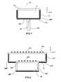
- the figure 1presents a single air cavity radiator element, of the Perot-Fabry type, according to an embodiment itself known from the state of the art and described in the patent application FR2901062 supra.
- a radiating element 10, shown in side sectional view in an XZ plane in the figure,may comprise an air resonant cavity 11 entirely delimited by a ground plane 110 at its bottom part situated in an XY plane, side walls 111 and a cover 112 at its upper part.
- the radiating element 10comprises excitation means 12, which can be supplied with radiofrequency signals.
- the excitation means 12may in particular comprise a supply port, for example formed by a metal waveguide 121 whose main axis is parallel to the Z axis, one of whose ends opens substantially at the level of the plane of Mass 110.
- the air resonant cavity 11has a transverse section, that is to say parallel to the XY plane, for example square, circular, hexagonal, or any other form that is compatible with the networking of the radiating element 10.
- the side walls 111may be of the "hard surface" type, that is to say for example made of a metallic material, in which longitudinal grooves are formed on either side of longitudinal ribs.
- the longitudinal groovescan be filled at least partially with a dielectric material.
- Longitudinal furrows and ribscan define periodic longitudinal structuring. As mentioned above, such a structuring is difficult to achieve in practice, and has a large footprint. In addition, the realization of such structuring is complicated by the need to load a dielectric material longitudinal grooves.
- the cover 112may for example be made of a thin or thick dielectric material.
- the dielectric materialmay for example comprise a face in which is formed a metal grid forming a semi-reflecting surface for increasing the excitation of the air resonant cavity 11 by the signals.
- the dielectric materialmay also comprise a face on which is formed a metal pad, said "patch", or a network of metal blocks, in order to induce a resonance complementary to that of the air resonant cavity 11.
- the cover 112can be made of a metallic material in which is formed a metal grid.
- the gate formed in the cover 112may advantageously have a variable pitch in at least one selected direction.
- the figure 2has a stacking radiating element of two air cavities of the Perrot-Fabry type, according to an embodiment itself known from the state of the art and described in the patent application FR2901062 supra.
- a radiating element 20may comprise two concentric air resonant cavities 21 and 22 cascaded; an upper cavity 21 disposed above a lower cavity 22. This cascading is used to excite by the feed port a lower cavity 22 of reduced dimensions, and thus to limit the excitation of higher modes in this lower cavity 22, then by coupling in the upper cavity 21.
- the radiationcan be better controlled, especially in the case of radiating elements 20 wide openings. It also makes it possible to reduce the reflectivities of the covers 212 and 222, and thus to more effectively couple the radiating element 20 to the supply access. The reflection losses in the access guide are reduced, and thus the adaptation of the input impedance of the radiating element 20 is facilitated.
- the upper cavity 21has substantially the same structure as the lower cavity 22.
- the radiating element 20comprises excitation means 12, these being able to feed the lower cavity 22.
- the transverse section of the upper cavity 21is greater than that of the lower cavity 22.
- the upper cavity 21is delimited in the XY plane by a first side wall 211, and covered at its upper part by a first cover 212.
- the first side wall 211may be secured to a first ground plane 210, for example formed on the lower surface of a first SBT substrate.
- the lower cavity 22is delimited by a second lateral wall 221 and covered by a second cover 222.
- the second lateral wall 221can be secured to a second ground plane 220, which can be formed on the lower surface of a second substrate SBT '.
- the first 212 and the first side wall 211may be made according to the configuration described above with reference to the figure 1 .
- the first substrate SBT and the first ground plane 210may include a through opening adapted to house the second cover 222 of the lower cavity 22.
- the covers 212 and 222may each comprise a metal grid 213, 223, more generally they may comprise partially reflecting surfaces.
- the Figures 3a and 3bhave a radiating element according to an exemplary embodiment of the invention, respectively in a sectional side view and a top view.
- a radiating element 30 presented in section in the XZ planemay comprise an upper cavity 31 concentric with a lower cavity 32, the upper cavity 31 being stacked on the lower cavity 32, in a manner similar to the example described above with reference to the figure 2 .
- the cavities 31, 32are essentially cylindrical in the embodiments given by way of examples and described in the figures.
- Alternative embodimentsmay also include cavities 31, 32 of substantially conical shape.
- the lower cavity 32may be powered by excitation means, for example a metallic waveguide 33, of cylindrical shape in the example illustrated by the figure.
- the upper cavity 31may be delimited at its upper part by a first cover 312, in its lateral part by a first side wall 311, and in its lower part by a first ground plane 310.
- the lower cavity 32may be delimited at its upper part by a second cover 322, in its lateral part by a second side wall 312, and in its lower part by a second ground plane 320.
- the ground planes 310, 320may for example be made in a metallic material.
- the side walls 311, 321may be made of a metallic material, and be free of dielectrics and / or reliefs.
- An openingmay be made in the first ground plane 310, of surface substantially corresponding to the surface of the lower cavity 32 in the XY plane, said opening giving way to the second cover 322.
- the covers 312, 322may be formed by surfaces partially reflective, for example by grids 313, 323.
- the grids 313, 323may be one-dimensional grids, such as son networks, the son being aligned with the polarization excitation.
- the grids 313, 323must have identical reflectivity characteristics for the two excitation polarizations, so they are two-dimensional grids, the alignment of which does not have to correspond to that of the excitation polarizations.
- the waveguide 33may emerge flush with the bottom of the lower cavity 32, or open into the lower cavity 32, slightly protruding from the bottom of the latter. Also, it may be envisaged to resort to means of adaptation, for example by iris.
- excitation meansby double feeds from the side, respectively for applications requiring a simple polarization or multiple polarization.
- double polarization excitationcan be achieved by a bottom feed as described above, together with a double feed from the side.
- the dual power suppliesopen orthogonal to the lateral surface of the lower cavity 32, and opposite each other with respect to the main axis.
- each dual power supplyis associated with a single access, for example by means of a suitable splitter, and all the power supplies are excited in a coherent manner, so that the excitations of the unwanted higher modes are filtered.
- Such structuresmake it possible to use the radiating element for applications requiring double polarization.
- corrugations 300may be formed, substantially below the first ground plane 310.
- the corrugations 300may be made of a metallic material, and may be of cylindrical shape, concentric of the resonant cavities 31, 32 In the example illustrated by the Figures 3a and 3b two cylindrical corrugations 300 are shown. In alternative embodiments, cylindrical corrugation may be contemplated. Also, more than two cylindrical corrugations may be disposed under the upper resonant cavity 31; it may be advantageous in such a case to use a plurality of corrugations 300 disposed periodically, that is to say that the spacing between two adjacent concentric corrugations remains constant.
- corrugations 300In general, it is necessary to resort to a greater number of corrugations 300, if the lateral size of the upper resonant cavity 31 is larger.
- the position of a corrugation 300may, for example, be characterized by its distance r C with respect to the main axis of the radiating element 30.
- the dimensioning of the corrugations 300may be characterized by their height I C , their thickness d C.
- the spacing between adjacent corrugationscan be characterized by the period a C.
- the height I C corrugations 300allows control of the frequency band where the higher mode is deleted. It is for example advantageous to choose the height I C of the order of a quarter of the nominal wavelength ⁇ 0 operating mode of the radiating element 30, this value allowing a deletion of the upper mode.
- the position of the corrugationsthat is to say the value r C , makes it possible to optimize the axial symmetry of the radiation pattern of the radiating element 30, that is to say the desired similarity between the diagrams of radiation in the plane E and in the plane H of the radiated electromagnetic wave. It may be advantageous to choose the value r C of the order of the nominal wavelength ⁇ 0 .
- a radiating elementintended to operate in a frequency band ranging from 2.48 GHz to 2.5 GHz
- the upper cavity 31 of whichis cylindrical in shape with a circular cross-section.
- the diameter of the lower cavity 32may for example be less than half the diameter of the upper cavity 31. In this typical example, it is of the order of 1 ⁇ 0 .
- Such a configurationmakes it possible to achieve a perfectly axisymmetric radiation pattern, ie with a constant lobe width regardless of the observation plane, and also characterized by a secondary lobe or SLL level of less than -20 dB. .
- ithas performances such that a directivity variation of between 16 dB and 16.2 dB, a variation of the surface efficiency of between 60% and 63%, a reflection coefficient
- a radiating element of similar structure without any corrugationis characterized by a non-axisymmetric radiation pattern, with a pinching of the lobe in the plane E associated with a rise in the secondary lobe or SLL, typically between -13 and -10 dB in the operating band.
- the cavities 31, 32 and the corrugations 300may be cylindrical with a circular section.
- Other embodiments of the invention, not shown in the figures,may for example comprise cavities 31, 32 and / or corrugations.
- the reflectivities of the partially reflecting surfaces 313, 323 formed by the covers 312, 322 of the cavities 31, 32may be adjusted to obtain concomitant matching and radiating bands.
- the lower cavity 32may be chosen smaller in size than the upper cavity 31.
- the partially reflecting surfaces 313, 323may be formed by grids, and the reflectivity of the grid associated with the lower cavity 32 may be small. value, in order to obtain a good adaptation.
- the reflectivity of the upper cavity 31may be of higher value, in order to spread the field over the opening of the radiating element, and achieve high directivities.
- a radiating element of similar structure without corrugationis mainly different in that the radiation pattern is non-axisymmetric, and is characterized by a pinching of the lobe in the plane E associated with a rise of the secondary lobe or SLL, typically between -13 and -10 dB in the operating band.
- the figure 4presents a radiating element according to another embodiment of the invention, in a side sectional view.
- a radiating element 30can be realized following a structure identical to the structure described above with reference to the Figures 3a and 3b but wherein the lower cavity 32 does not include a hood.
- Such a radiating element structurecomprises only one gate 313, and hence is simpler and less expensive to produce.
- the removal of the grid in the lower cavity 32is indeed possible because the only sudden transition between the lower cavity 32 and the upper cavity 31 generates a reflection phenomenon, a lower resonant cavity then being defined without a metal grid being necessary.
- Such a structureis for example suitable for apertures of the radiating element ranging from 1 to 3 ⁇ 0 , for example for S-band or Ku-band applications, the configuration being given previously by way of example corresponding to a band application. Ku.
- FIG. 5presents an advantageous embodiment, in which a polarizer is integrated in the actual structure of the radiating element.
- a radiating element 50 shown in a side sectional view in an XZ planecan be made in a structure similar to the structures of the radiating element 30 described above with reference to the Figures 3a, 3b and 4 .
- a structure similar to the structure illustrated by the figure 4is chosen.
- the radiating element 50thus comprises in particular a lower cavity 32 fed by excitation means formed by a waveguide 33.
- the upper cavity 31is covered by a cover formed by a grid 313 constituting a partially reflecting surface.
- a simple corrugationis performed substantially under the upper cavity 31.
- a polarizing radome 51can be made in the upper part of the upper cavity 31.
- the polarizing radome 51can be formed by the combination of at least two polarizing frequency selective surfaces, designated polarizing FSS according to the English terminology "Frequency Selective Surface".
- polarizing FSSpolarizing frequency selective surfaces
- a polarizing radomeis itself known from the state of the art, and makes it possible to induce a phase difference between the two components of the electric field E x and E y of the electromagnetic wave.
- the polarizing radome 51When this phase difference is ⁇ 90 °, the polarizing radome 51, excited in linear polarization in an oblique direction in the XY plane, that is to say at + 45 ° by means of the X axis, generates a right circular polarization, and excited in linear polarization in a direction of -45 °, generates a left circular polarization. It should be observed that the polarizing radome 51 transforms a linear dual-polarization type operation into circular double-polarization type operation.
- the polarizing radome 51may be of the "double-FSS" type, and comprise two polarizing FSSs 511 and 512 arranged parallel to one another above, and separated by a distance D FSS .
- the lower FSS 512is arranged parallel to the gate 313 at a distance D 3 from the latter.
- a double FSS type configurationmakes it possible to obtain a wider bandwidth, and a signal transmission without loss, the signal transmission not inducing a return to the upper cavity 31. It is not possible to with a single layer polarizing radome, obtain a lossless transmission, and a phase shift of 90 ° according to the two components E x and E y of the incident signal.
- the two polarizing FSSs 511 and 512are identical and separated by a guided half-wavelength, in order to simultaneously obtain lossless transmission of the incident signal, and a phase quadrature delay. between the two orthogonal components of the transmitted signal.
- the polarizing radome 51is positioned above the radiating element 50 designed to radiate in double linear polarization, at a distance typically of the order of a quarter of a guided wavelength. Thus, the polarizing radome 51 does not fundamentally disturb the operation of the radiating element 50. A slight modification of the dimensions of the patterns of the FSS can be adjusted in order to refine the radiation and the adaptation of the radiating element 50 .
- the polarizing FSSscan be of the inductive or capacitive type: the polarizing FSS of the inductive type being essentially formed by metal surfaces in which slit-defined patterns are formed, the capacitive-type polarizing FSS being essentially formed by surfaces on which metallic patterns are made.
- the use of inductive type FSScan be advantageous because it does not require the use of a substrate, the FSS can then be directly made of a metallic material.
- Each polarizing FSS 511, 512may for example be made in the form of a metal plate provided with slots.
- cross slot cells 520designated "cross slots" cells according to the English terminology, may be arranged on the metal plate, for example in a periodic pattern.
- a cross slot cell 520is shown in plan view on the figure 5 .
- the cross slot cell 520is particularly characterized by the length of its side, or period a, by the length and the width respectively at y and d y of the horizontal slot (that is to say along the X axis ), as well as the length and width a x and d x of the vertical slot (along the Y axis).
- the reflectivity according to a given polarizationis adjusted by varying the length of the slot perpendicular to this polarization. Knowing that the reflectivity of the slot is zero at resonance, and that before its resonance the slot has a negative phase reflection coefficient and after the resonance a positive phase, the cross slots have different lengths according to each of the two polarizations of way to create a phase shift of 90 ° between the two polarizations, and thus generate a circular polarization. For example, the lengths at x and y slots can be determined so that one of the slots has an action on frequencies below the resonant frequency, and the other slots for higher frequencies.
- the polarizing radomeconsisting of two separate FSS for example a distance D FSS equal to ⁇ 0/2 or close to this value, a phase difference of 90 ° in transmission between the components E x and E y .
- a phase difference of 90 ° in transmission between the components E x and E yFor example, it is possible to set the length a x of the vertical slot to a value less than ⁇ 0/2 , and the length y of the horizontal slot to a value greater than ⁇ 0 / d2. It is of course reciprocally possible to set the length a y of the horizontal slot to a value less than ⁇ 0/2 , and the length a x of the vertical slot to a value greater than ⁇ 0/2 .
- Period amust be set to a value greater than a x and a y .
- Slit widths d x and d yare adjusted according to the thickness of the metal plate. Typically, the widths of the slots d x and d y are chosen well below the nominal wavelength ⁇ 0 .
- the aforementioned embodimentis based on cross-shaped slot cells 520 arranged in a square mesh, but it is also possible to use cells arranged in a different mesh, for example round, hexagonal, ...
- patterns other than crossesmay be used, for example annular slots, or Jerusalem Cross type slits, etc.
- FIG. 6a and 6bhave a radiating element according to another embodiment of the invention, respectively in a side sectional view, and in a perspective view.
- a radiating element 60may have a structure substantially similar to the structure of the radiating element 50 described above with reference to the figure 5 .
- the radiating element 60comprises in particular an upper cavity 31, a lower cavity 32 fed by a waveguide 33.
- the upper cavity 31is in this example covered by a cover formed by a grid 313.
- Corrugations 300are made substantially below the upper cavity 31.
- the side walls of the upper and lower cavities 31, 32are cylindrical in shape, circular section.
- a polarizing radome 61is produced above the upper cavity 31.
- the polarizing radome 61is also of cylindrical shape, but with a square section.
- the polarizing radome 61is delimited in its lateral part by side walls of substantially cylindrical shape, with a square section.
- the use of a square sectionallows here to have a larger number of square cross-shaped slot cells 620 on the surface of polarizing FSSs 611, 612 formed by two metal plates arranged parallel to each other.
- a radiating elementintended to operate in a frequency band ranging from 2.48 GHz to 2.5 GHz, the polarizing radome 61 of which is square in shape, the side of which has a length of the order of 2.7x ⁇ 0 .
- Such a configurationmakes it possible to achieve circular double polarization, that is to say right and left, by exciting the antenna by two linear polarizations + 45 ° to -45 °.
- the radiation patternsare perfectly axisymmetric, that is to say that the lobe width is constant regardless of the observation plane, and also characterized by a secondary lobe level or SLL less than - 25 dB.
- the directivityvaries between 16.5 dB and 16.7 dB, and the surface efficiency is between 63% and 66%.
- is less than -20 dB and the axial ratio is less than 1 dB on the band of interest.
Landscapes
- Aerials With Secondary Devices (AREA)
- Variable-Direction Aerials And Aerial Arrays (AREA)
- Waveguide Aerials (AREA)
Description
Translated fromFrenchLa présente invention concerne le domaine des éléments rayonnants, notamment pour les bandes de fréquences basses, plus particulièrement les bandes de fréquences se situant en dessous de la bande S, et employés dans des applications nécessitant de rayonner de la puissance, pouvant également être utilisés dans des antennes réseau. Elle s'applique notamment aux antennes utilisées dans des satellites de télécommunication.The present invention relates to the field of radiating elements, in particular for the low frequency bands, more particularly the frequency bands lying below the S band, and used in applications requiring the radiating of power, which can also be used in network antennas. It applies in particular to antennas used in telecommunication satellites.
Le terme "élément rayonnant" désigne une combinaison d'au moins un plan de masse rayonnant, de moyens d'excitation destinés à être alimentés en signaux, et d'une cavité résonante chargée, de rayonner de l'énergie représentative de ces signaux selon une longueur d'onde λ0 choisie.The term "radiating element" denotes a combination of at least one radiating ground plane, excitation means intended to be supplied with signals, and a charged resonant cavity, of radiating energy representative of these signals according to a wavelength λ0 chosen.
Les éléments rayonnants utilisés dans des antennes réseau doivent typiquement présenter l'une au moins des caractéristiques suivantes : une forte efficacité de surface et/ou un faible encombrement et une faible masse et/ou la capacité à être excité de manière compacte en simple ou bi-polarisation et/ou une bande passante compatible avec l'application visée.The radiating elements used in network antennas must typically have at least one of the following characteristics: a high surface efficiency and / or a small footprint and a low mass and / or the ability to be excited compactly in single or dual -polarization and / or a bandwidth compatible with the intended application.
La caractéristique de forte efficacité de surface est particulièrement importante dans des utilisations d'éléments rayonnants dans des antennes réseau, du fait qu'elle permet d'optimiser le gain et de réduire les niveaux des lobes secondaires et des lobes de réseau. Or, comme cela est explicité ci-après, cette caractéristique est difficilement compatible avec certaines des autres caractéristiques, et notamment celles de compacité et d'intégration, quelle que soit la bande de fréquence concernée.The feature of high surface efficiency is particularly important in uses of radiating elements in network antennas, because it optimizes the gain and reduces the levels of side lobes and lattice lobes. However, as explained below, this characteristic is hardly compatible with some of the other characteristics, and in particular those of compactness and integration, regardless of the frequency band concerned.
Le terme "antenne réseau" désigne aussi bien les antennes réseau actives à rayonnement direct que les antennes réseau focales, ces dernières ayant un ou plusieurs réflecteur(s) focalisant(s), avec un réseau de sources élémentaires placé dans la zone focale. Une telle géométrie d'antenne est communément désignée par le sigle FAFR correspondant à la terminologie anglaise "Focal Array Fed Reflector". Au sein d'une telle antenne, chaque faisceau ou "spot" est réalisé par le regroupement cohérent des signaux d'un sous-ensemble des sources élémentaires, avec des amplitudes et phases appropriées pour obtenir le diagramme d'antenne voulu, notamment la taille et la direction de visée du lobe principal de rayonnement.The term "network antenna" designates both active direct radiation network antennas and focal network antennas, the latter having one or more focusing reflectors, with an array of elementary sources placed in the focal zone. Such an antenna geometry is commonly referred to by the acronym FAFR corresponding to the English terminology "Focal Array Fed Reflector". Within such an antenna, each beam or "spot" is achieved by coherently grouping the signals of a subset of the elementary sources, with appropriate amplitudes and phases to obtain the desired antenna pattern, including the size and direction of aiming of the main lobe of radiation.
Dans les bandes de fréquences basses, comme par exemple la bande L ou S, les éléments rayonnants, quelles que soient les applications pour lesquelles ils sont destinés, visent à suppléer les cornets, trop encombrants. Les cornets les plus compacts sont de type cornet de Potter; ils ont une dimension longitudinale typiquement supérieure à 3λ0, où λ0 est la longueur d'onde dans le vide; par exemple, λ0 est de l'ordre de 150 mm en bande S. Ces cornets de Potter sont limités en ouverture rayonnante, et donc en gain. De plus grandes dimensions nécessitent des longueurs plus importantes. Par conséquent, les cornets de Potter présentent un encombrement longitudinal significatif, ainsi qu'une masse importante.In the low frequency bands, such as the L or S band, the radiating elements, whatever the applications for which they are intended, are intended to supply the cones, too bulky. The most compact horns are of the Potter horn type; they have a longitudinal dimension typically greater than 3λ0 , where λ0 is the wavelength in vacuum; for example, λ0 is of the order of 150 mm in S-band. These Potter's horns are limited in radiating aperture, and thus in gain. Larger dimensions require longer lengths. As a result, Potter's turbinates have significant longitudinal bulk, as well as a large mass.
Les sous-réseaux, par exemple planaires dans le cas d'applications spatiales, ne sont également pas satisfaisants, en terme de pertes et de compatibilité à des fonctionnements à forte puissance.Subnets, for example planar in the case of space applications, are also not satisfactory, in terms of losses and compatibility with high power operations.
Un premier type de sous-réseau planaire consiste en des éléments rayonnants de type pavé, encore désignés "patches" selon la terminologie anglaise, reliés par un répartiteur triplaque. Ce répartiteur est relativement complexe et permet difficilement de réaliser un sous-réseau permettant la bipolarisation, voire un fonctionnement bi-bande. Les pertes générées dans ce réseau peuvent être également significatives.A first type of planar subnetwork consists of radiating elements of cobblestone type, also called "patches" according to English terminology, connected by a triplate splitter. This splitter is relatively complex and makes it difficult to achieve a sub-network allowing bipolarization or even a dual-band operation. The losses generated in this network can also be significant.
Un second type de sous-réseau, notamment décrit dans la demande de brevet français publiée sous la référence
Une simplification aux sous-réseaux du second type a été proposée. Elle consiste à remplacer, d'une part, les pavés parasites par une grille métallique réalisant une interface semi-réfléchissante facilitant l'établissement du champ électromagnétique dans la cavité, et d'autre part, le pavé excitateur par un excitateur guidé, de manière à définir une cavité de type Pérot-Fabry, comme dans le cas d'un ERDV. L'élément rayonnant est alors entièrement métallique, compatible avec des applications requérant une forte puissance, beaucoup plus simple à définir qu'un élément ERDV classique, et permet d'atteindre des ouvertures rayonnantes plus importantes qu'un élément ERDV classique. Cependant, un tel élément rayonnant possède deux inconvénients : l'obtention d'ouvertures rayonnantes de dimensions importantes nécessite des grilles de fortes réflectivités, pour que le champ électromagnétique s'établisse dans la cavité de type Pérot-Fabry. L'utilisation de ces fortes réflectivités génère un retour important du signal vers le guide d'accès, et l'adaptation de l'élément rayonnant est très délicate et valide seulement sur une bande de fréquence très étroite. D'autre part, lorsqu'une forte efficacité de surface est requise, il est alors nécessaire, pour insérer l'élément rayonnant dans une antenne réseau, de contraindre l'expansion du champ électromagnétique dans la cavité, par l'intermédiaire de parois métalliques. Ces dernières induisent une distribution non uniforme du champ dans la cavité métallique. Certes, l'utilisation de grilles à pas variable permet d'améliorer la distribution du champ en provoquant une réflexion plus importante au centre qu'en périphérie, mais alors la structure complète devient très difficile à adapter.A simplification to the subnetworks of the second type has been proposed. It consists in replacing, on the one hand, the parasitic blocks by a metal grid realizing a semi-reflective interface facilitating the establishment of the electromagnetic field in the cavity, and on the other hand, the exciter pad by a guided exciter, so to define a Pérot-Fabry cavity, as in the case of an ERDV. The radiating element is then entirely metallic, compatible with applications requiring a high power, much simpler to define than a conventional ERDV element, and makes it possible to reach larger radiating openings than a conventional ERDV element. However, such a radiating element has two disadvantages: obtaining large radiating openings requires grids of high reflectivities, so that the electromagnetic field is established in the Perot-Fabry type cavity. The use of these strong reflectivities generates a significant return of the signal towards the access guide, and the adaptation of the radiating element is very delicate and valid only on a very narrow frequency band. On the other hand, when a high surface efficiency is required, it is then necessary, to insert the radiating element in a network antenna, to constrain the expansion of the electromagnetic field in the cavity, via metal walls. . These induce a non-uniform distribution of the field in the metal cavity. Admittedly, the use of variable pitch grids makes it possible to improve the distribution of the field by causing greater reflection at the center than at the periphery, but then the complete structure becomes very difficult to adapt.
Une solution est proposée dans la demande de brevet français publiée sous la référence
Enfin, il est nécessaire d'associer à des éléments rayonnants d'antennes des dispositifs de polarisation. Par exemple, les éléments rayonnants doivent pouvoir être excités en simple polarisation et/ou en bipolarisation et/ou en polarisation circulaire. D'une manière typique, dans les antennes comprenant des éléments rayonnants de type cornet, la dimension du polariseur est du même ordre de grandeur que la dimension du cornet. Ainsi, l'encombrement des antennes est fortement impacté par l'adjonction de polariseurs.Finally, it is necessary to associate polarization devices with antennas. For example, the radiating elements must be able to be excited in single polarization and / or in bipolarization and / or in circular polarization. Typically, in antennas comprising horn type radiators, the size of the polarizer is of the same order of magnitude as the size of the horn. Thus, the size of the antennas is strongly impacted by the addition of polarizers.
Un but de la présente invention est de pallier au moins les inconvénients précités, en proposant un élément rayonnant à cavités résonantes à fort rendement de surface, dont la structure est particulièrement compacte, et confère un compromis optimal entre une forte efficacité de surface, un faible encombrement et une faible masse, ainsi que la capacité à être excité en simple polarisation ou en bipolarisation.An object of the present invention is to overcome at least the aforementioned drawbacks, by proposing a radiating element with resonant cavities with high surface efficiency, whose structure is particularly compact, and confers an optimal compromise between a high surface efficiency, a low congestion and low mass, as well as the ability to be excited in single polarization or bipolarization.
A cet effet, la présente invention a pour objet un élément rayonnant comprenant au moins deux cavités résonantes concentriques, formées par une cavité inférieure alimentée par des moyens d'excitation, et une cavité supérieure empilée sur la cavité inférieure, chacune desdites cavités résonantes étant délimitée en sa partie inférieure par un plan de masse, en sa partie latérale par une paroi latérale essentiellement cylindrique ou conique, au moins la cavité supérieure étant délimitée en sa partie supérieure par un premier capot essentiellement plan, l'élément rayonnant étant caractérisé en ce que des corrugations essentiellement de forme cylindrique et concentriques des cavités résonantes, sont formées sensiblement en dessous du premier plan de masse de la cavité résonante supérieure.For this purpose, the subject of the present invention is a radiating element comprising at least two concentric resonant cavities, formed by a lower cavity fed by excitation means, and an upper cavity stacked on the lower cavity, each of said resonant cavities being delimited. in its lower part by a ground plane, in its lateral part by a substantially cylindrical or conical side wall, at least the upper cavity being delimited at its upper part by a first substantially plane cover, the radiating element being characterized in that essentially cylindrical and concentric corrugations of the resonant cavities are formed substantially below the first ground plane of the upper resonant cavity.
Dans un mode de réalisation de l'invention, les parois latérales peuvent être de forme essentiellement cylindrique.In one embodiment of the invention, the sidewalls may be substantially cylindrical in shape.
Dans un mode de réalisation de l'invention, les parois latérales peuvent être de forme essentiellement conique.In one embodiment of the invention, the sidewalls may be substantially conical in shape.
Dans un mode de réalisation de l'invention, la cavité inférieure peut être également délimitée en sa partie supérieure, sensiblement au niveau de la partie inférieure de la cavité supérieure, par un second capot.In one embodiment of the invention, the lower cavity may also be delimited at its upper part, substantially at the level of the lower part of the upper cavity, by a second cap.
Dans un mode de réalisation de l'invention, les plans de masse, les capots, les parois latérales et les corrugations peuvent être essentiellement réalisées dans un matériau métallique.In one embodiment of the invention, the ground planes, the covers, the side walls and the corrugations may be essentially made of a metallic material.
Dans un mode de réalisation de l'invention, les capots peuvent être formés par une surface partiellement réfléchissante.In one embodiment of the invention, the covers may be formed by a partially reflecting surface.
Dans un mode de réalisation de l'invention, les capots peuvent être formés par une grille métallique.In one embodiment of the invention, the covers may be formed by a metal grid.
Dans un mode de réalisation de l'invention, les capots peuvent être formés par un matériau diélectrique.In one embodiment of the invention, the covers may be formed by a dielectric material.
Dans un mode de réalisation de l'invention, l'élément rayonnant peut être caractérisé en ce qu'un radome polarisant est réalisé en la partie supérieure de la cavité supérieure.In one embodiment of the invention, the radiating element may be characterized in that a polarizing radome is formed in the upper part of the upper cavity.
Dans un mode de réalisation de l'invention, le radome polarisant peut être formé par deux surfaces sélectives de fréquence polarisantes dites FSS polarisantes essentiellement planes, disposées parallèlement l'une de l'autre, et parallèlement et sensiblement au-dessus dudit premier capot.In one embodiment of the invention, the polarizing radome may be formed by two polarizing frequency selective surfaces called FSS. polarizers substantially planar, arranged parallel to each other, and parallel and substantially above said first hood.
Dans un mode de réalisation de l'invention, chaque FSS polarisante peut être formée par une plaque métallique comprenant une pluralité de fentes.In one embodiment of the invention, each polarizing FSS may be formed by a metal plate having a plurality of slots.
Dans un mode de réalisation de l'invention, chaque FSS polarisante peut être formée par une plaque métallique comprenant une pluralité de cellules fentes en croix.In one embodiment of the invention, each polarizing FSS may be formed by a metal plate comprising a plurality of cross-slot cells.
Dans un mode de réalisation de l'invention, chaque FSS polarisante peut être formée par une plaque métallique comprenant une pluralité de cellules fentes en croix disposées selon un motif périodique sur la surface de la plaque métallique.In one embodiment of the invention, each polarizing FSS may be formed by a metal plate comprising a plurality of cross-slotted cells arranged in a periodic pattern on the surface of the metal plate.
Dans un mode de réalisation de l'invention, les parois latérales et les corrugations peuvent être cylindriques à section circulaire.In one embodiment of the invention, the side walls and the corrugations may be cylindrical with circular section.
Dans un mode de réalisation de l'invention, lesdits moyens d'excitation peuvent comprendre au moins un guide d'alimentation concentrique des cavités résonantes et débouchant directement, ou via des moyens d'adaptation, dans la cavité inférieure.In one embodiment of the invention, said excitation means may comprise at least one concentric supply guide of the resonant cavities and opening directly, or via adaptation means, into the lower cavity.
Dans un mode de réalisation de l'invention, lesdits moyens d'excitation peuvent comprendre au moins une alimentation double formée par deux guides d'onde latéraux débouchant de manière symétrique par rapport à l'axe principal de la cavité inférieure, sensiblement au niveau de la paroi latérale de la cavité inférieure, les signaux convoyés par les moyens d'excitation étant accordés en phase de manière à ce que les modes supérieurs indésirables soient filtrés.In one embodiment of the invention, said excitation means may comprise at least one double feed formed by two lateral waveguides opening symmetrically with respect to the main axis of the lower cavity, substantially at the level of the side wall of the lower cavity, the signals conveyed by the excitation means being tuned in phase so that the unwanted upper modes are filtered.
Dans un mode de réalisation de l'invention, lesdits moyens d'excitation peuvent comprendre au moins un guide d'alimentation concentrique des cavités résonantes et débouchant directement, ou via des moyens d'adaptation, dans la cavité inférieure, et au moins une alimentation double formée par deux guides d'onde latéraux débouchant de manière symétrique par rapport à l'axe principal de la cavité inférieure, sensiblement au niveau de la paroi latérale de la cavité inférieure, les signaux convoyés par les moyens d'excitation étant accordés en phase de manière à ce que les modes supérieurs indésirables soient filtrés.In one embodiment of the invention, said excitation means may comprise at least one concentric supply guide of the resonant cavities and opening directly, or via adaptation means, into the lower cavity, and at least one power supply. double formed by two lateral waveguides opening symmetrically with respect to the main axis of the lower cavity, substantially at the sidewall of the lower cavity, the signals conveyed by the excitation means being tuned in phase so that the unwanted top modes are filtered.
Dans un mode de réalisation de l'invention, un radome polarisant peut être réalisé au-dessus de la cavité supérieure, le radome polarisant étant essentiellement de forme cylindrique et concentrique des cavités résonantes.In one embodiment of the invention, a polarizing radome can be made above the upper cavity, the polarizing radome being substantially cylindrical and concentric resonant cavities.
Dans un mode de réalisation de l'invention, le radome polarisant peut être essentiellement de forme cylindrique à section carrée.In one embodiment of the invention, the polarizing radome may be substantially cylindrical in shape with a square section.
La présente invention a également pour objet une antenne réseau caractérisée en ce qu'elle comprend un ou une pluralité d'éléments rayonnants tels que décrits ci-dessus.The present invention also relates to a network antenna characterized in that it comprises one or a plurality of radiating elements as described above.
D'autres caractéristiques et avantages de l'invention apparaîtront à la lecture de la description, donnée à titre d'exemple, faite en regard des dessins annexés qui représentent :
- la
figure 1 , un élément rayonnant à cavité à air unique, de structure en elle-même connue de l'état de la technique ; - la
figure 2 , un élément rayonnant à empilement de deux cavités à air, de structure en elle-même connue de l'état de la technique ; - les
figures 3a et 3b , un élément rayonnant selon un exemple de réalisation de l'invention, respectivement en vue en coupe latérale et en vue de dessus ; - la
figure 4 , un élément rayonnant selon un autre exemple de réalisation de l'invention, dans une vue en coupe latérale ; - la
figure 5 , un élément rayonnant selon un autre exemple de réalisation de l'invention, dans une vue en coupe latérale ; - les
figures 6a et 6b , un élément rayonnant selon un autre exemple de réalisation de l'invention, respectivement dans une vue en coupe latérale, et dans une vue en perspective.
- the
figure 1 a radiating element with a single air cavity, of a structure that is itself known from the state of the art; - the
figure 2 a radiating element with a stack of two air cavities, with a structure of itself known from the state of the art; - the
Figures 3a and 3b , a radiating element according to an exemplary embodiment of the invention, respectively in lateral sectional view and in top view; - the
figure 4 , a radiating element according to another embodiment of the invention, in a side sectional view; - the
figure 5 , a radiating element according to another embodiment of the invention, in a side sectional view; - the
Figures 6a and 6b , a radiating element according to another embodiment of the invention, respectively in a side sectional view, and in a perspective view.
La
Un élément rayonnant 10, présenté en vue en coupe latérale dans un plan XZ sur la figure, peut comprendre une cavité résonante à air 11 entièrement délimitée par un plan de masse 110 en sa partie inférieure situé dans un plan XY, des parois latérales 111 et un capot 112 en sa partie supérieure. L'élément rayonnant 10 comprend des moyens d'excitation 12, pouvant être alimentés en signaux radiofréquence. Les moyens d'excitation 12 peuvent notamment comprendre un accès d'alimentation, par exemple formée par un guide d'onde métallique 121 dont l'axe principal est parallèle à l'axe Z, dont une des extrémités débouche sensiblement au niveau du plan de masse 110.A radiating
La cavité résonante à air 11 présente une section transverse, c'est-à-dire parallèle au plan XY, par exemple de forme carrée, circulaire, hexagonale, ou encore de toute autre forme qui soit compatible de la mise en réseau de l'élément rayonnant 10.The air
Dans l'exemple de réalisation illustré par la
Le capot 112 peut par exemple être réalisé dans un matériau diélectrique fin ou épais. Le matériau diélectrique peut par exemple comprendre une face dans laquelle est formée une grille métallique formant une surface semi-réfléchissante permettant d'augmenter l'excitation de la cavité résonante à air 11 par les signaux. Le matériau diélectrique peut également comprendre une face sur laquelle est formé un pavé métallique, dit "patch", ou un réseau de pavés métalliques, afin d'induire une résonance complémentaire à celle de la cavité résonante à air 11. Egalement, le capot 112 peut être réalisé dans un matériau métallique dans lequel est formée une grille métallique. La grille formée dans le capot 112 peut avantageusement présenter un pas variable dans au moins une direction choisie.The
La
Un élément rayonnant 20 peut comporter deux cavités résonantes à air 21 et 22 concentriques mises en cascade ; une cavité supérieure 21 disposée au-dessus d'une cavité inférieure 22. Cette mise en cascade permet d'exciter par l'accès d'alimentation une cavité inférieure 22 de dimensions réduites, et ainsi de limiter l'excitation de modes supérieurs dans cette cavité inférieure 22, puis par couplage dans la cavité supérieure 21. Le rayonnement peut ainsi être mieux maîtrisé, notamment dans le cas d'éléments rayonnants 20 d'ouvertures larges. Elle permet également de réduire les réflectivités des capots 212 et 222, et donc de coupler plus efficacement l'élément rayonnant 20 à l'accès d'alimentation. Les pertes par réflexion dans le guide d'accès sont réduites, et ainsi l'adaptation de l'impédance d'entrée de l'élément rayonnant 20 est facilitée.A radiating element 20 may comprise two concentric air
La cavité supérieure 21 présente sensiblement la même structure que la cavité inférieure 22. D'une manière similaire à la structure à une cavité décrite précédemment en référence à la
La cavité supérieure 21 est délimitée dans le plan XY par une première paroi latérale 211, et couverte en sa partie supérieure par un premier capot 212. La première paroi latérale 211 peut être solidarisée à un premier plan de masse 210, par exemple formé sur la surface inférieure d'un premier substrat SBT. De la même manière, la cavité inférieure 22 est délimitée par une seconde paroi latérale 221 et couverte par un second capot 222. La seconde paroi latérale 221 peut être solidarisée à un second plan de masse 220, pouvant être formé sur la surface inférieure d'un second substrat SBT'. Le premier 212 et la première paroi latérale 211 peuvent être réalisés selon la configuration décrite précédemment en référence à la
Les exemples de réalisation de la présente invention décrits en détail ci-après en référence aux figures suivantes, s'appliquent à une structure comprenant au moins deux cavités résonantes empilées, cependant ceux-ci peuvent également s'appliquer à des structures comprenant un empilement d'une pluralité de cavités résonantes à air. La présente invention propose de ne pas recourir aux parois latérales des cavités résonantes pour pallier les problèmes liés aux modes supérieurs électromagnétiques.The embodiments of the present invention described in detail hereinafter with reference to the following figures, apply to a structure comprising at least two stacked resonant cavities, however these can also be applied to structures comprising a stack of a plurality of air resonant cavities. The present invention proposes not to use the side walls of the resonant cavities to overcome the problems related to the upper electromagnetic modes.
Les
Dans l'exemple illustré par la
Le guide d'onde 33 peut par exemple déboucher à fleur du fond de la cavité inférieure 32, ou bien déboucher dans la cavité inférieure 32, en dépassant légèrement du fond de celle-ci. Egalement, il peut être envisagé de faire recours à des moyens d'adaptation, par exemple par iris.For example, the
Dans un mode de réalisation alternatif, non représenté sur les figures, il est également possible de former des moyens d'excitation par alimentations doubles par le côté, respectivement pour des applications requérant une simple polarisation ou une polarisation multiple. Egalement, une excitation en polarisation double peut être obtenue par une alimentation par le dessous telle que décrite ci-dessus, conjointement à une alimentation double par le côté. Les alimentations doubles débouchent à l'orthogonale de la surface latérale de la cavité inférieure 32, et à l'opposé l'une de l'autre par rapport à l'axe principal. Dans ces divers modes de réalisation, chaque alimentation double est associée à un unique accès par exemple au moyen d'un répartiteur adéquat, et toutes les alimentations sont excitées de manière cohérente, de sorte que les excitations des modes supérieurs indésirables soient filtrées. De telles structures permettent d'utiliser l'élément rayonnant pour des applications nécessitant une polarisation double.In an alternative embodiment, not shown in the figures, it is also possible to form excitation means by double feeds from the side, respectively for applications requiring a simple polarization or multiple polarization. Also, double polarization excitation can be achieved by a bottom feed as described above, together with a double feed from the side. The dual power supplies open orthogonal to the lateral surface of the
Selon une particularité de la présente invention, des corrugations 300 peuvent être formées, sensiblement en dessous du premier plan de masse 310. Les corrugations 300 peuvent être réalisées dans un matériau métallique, et peuvent être de forme cylindrique, concentriques des cavités résonantes 31, 32. Dans l'exemple illustré par les
D'une manière générale, il est nécessaire de recourir à un plus grand nombre de corrugations 300, si la taille latérale de la cavité résonante supérieure 31 est plus grande. La position d'une corrugation 300 peut par exemple être caractérisée par sa distance rC par rapport à l'axe principal de l'élément rayonnant 30. Le dimensionnement des corrugations 300 peut être caractérisé par leur hauteur IC, leur épaisseur dC. Dans le cas où plusieurs corrugations 300 concentriques disposées de manière périodique sont utilisées, l'écartement entre des corrugations voisines peut être caractérisé par la période aC.In general, it is necessary to resort to a greater number of
La hauteur IC des corrugations 300 permet un contrôle de la bande de fréquence où le mode supérieur est supprimé. Il est par exemple avantageux de choisir la hauteur IC de l'ordre du quart de la longueur d'onde nominale λ0 de fonctionnement de l'élément rayonnant 30, cette valeur permettant une suppression du mode supérieur.The height IC corrugations 300 allows control of the frequency band where the higher mode is deleted. It is for example advantageous to choose the height IC of the order of a quarter of the nominal wavelength λ0 operating mode of the radiating
La position des corrugations, c'est-à-dire la valeur rC, permet d'optimiser la symétrie axiale du diagramme de rayonnement de l'élément rayonnant 30, c'est-à-dire la similarité, souhaitée, entre les diagrammes de rayonnement dans le plan E et dans le plan H de l'onde éléctromagnétique rayonnée. Il peut être avantageux de choisir la valeur rC de l'ordre de la longueur d'onde nominale λ0.The position of the corrugations, that is to say the value rC , makes it possible to optimize the axial symmetry of the radiation pattern of the radiating
Dans un exemple typique, il est par exemple possible de réaliser un élément rayonnant 30 destiné à fonctionner dans une bande de fréquence s'étalant de 2,48 GHz à 2,5 GHz, dont la cavité supérieure 31 est de forme cylindrique à section circulaire, d'un diamètre de l'ordre de 2,5xλ0, comportant une unique corrugation 300 cylindrique à section circulaire, disposée à 118 mm de l'axe principal de l'élément rayonnant 30, d'une hauteur de 31 mm et d'une largeur de 3.7 mm. Le diamètre de la cavité inférieure 32 peut par exemple être inférieur à la moitié du diamètre de la cavité supérieure 31. Dans cet exemple typique, il est de l'ordre de 1λ0. Une telle configuration permet d'atteindre un diagramme de rayonnement parfaitement axisymétrique, c'est à dire dont la largeur du lobe est constante quelque soit le plan d'observation, et également caractérisé par un niveau de lobe secondaire ou SLL inférieur à -20 dB. En outre, il possède des performances telles qu'une variation de directivité comprise entre 16 dB et 16,2 dB, une variation de l'efficacité de surface comprise entre 60% et 63%, un coefficient de réflexion |S11| inférieur à -25 dB. En comparaison, un élément rayonnant de structure similaire ne comportant pas de corrugation est caractérisé par un diagramme de rayonnement non axisymétrique, avec un pincement du lobe dans le plan E associé à une remontée des lobe secondaire ou SLL, typiquement entre -13 et -10 dB dans la bande de fonctionnement.In a typical example, it is possible, for example, to produce a radiating element intended to operate in a frequency band ranging from 2.48 GHz to 2.5 GHz, the
Ainsi que cela est illustré par la
Les réflectivités des surfaces partiellement réfléchissantes 313, 323 formées par les capots 312, 322 des cavités 31, 32 peuvent être ajustées afin d'obtenir des bandes d'adaptation et de rayonnement concomitantes. La cavité inférieure 32 peut être choisie de dimension plus réduite que la cavité supérieure 31. Par exemple, les surfaces partiellement réfléchissantes 313, 323 peuvent être formées par des grilles, et la réflectivité de la grille associée à la cavité inférieure 32 peut être de faible valeur, dans le but d'obtenir une bonne adaptation. La réflectivité de la cavité supérieure 31 peut être de valeur plus élevée, dans le but d'étaler le champ sur l'ouverture de l'élément rayonnant, et d'atteindre de fortes directivités.The reflectivities of the partially reflecting
Des valeurs peuvent être données ici à titre d'exemple non limitatif de réalisation de l'invention : il est par exemple possible de réaliser un élément rayonnant 30 bande Ku de simple polarisation linéaire, avec corrugation 300, destiné à opérer dans une bande de fréquence s'étalant de 11,8 à 13,2 GHz, dont l'ouverture est de l'ordre de 1,85xλ0, dont l'épaisseur, c'est-à-dire l'épaisseur cumulée des deux cavités résonantes 31, 32, est de l'ordre de λ0, dont les capots 312, 322 sont respectivement formés par des grilles semi-réfléchissantes respectivement de coefficients de réflectivités (en puissance) égaux à 20% et à 30%. Une telle configuration permet d'atteindre un diagramme de rayonnement axisymétrique et caractérisé par un niveau de lobe secondaire ou SLL inférieur à -18 dB. En outre, il possède des performances telles qu'une variation de directivité comprise entre 14,59 dB et 15,39 dB, une variation de l'efficacité de surface comprise entre 71,9% et 77,6%, ainsi qu'un coefficient de réflexion |S11| inférieur à -15,5 dB. En comparaison, un élément rayonnant de structure similaire ne comportant pas de corrugation est principalement différent en ce que le diagramme de rayonnement est non axisymétrique, et se caractérise par un pincement du lobe dans le plan E associé à une remontée des lobe secondaire ou SLL, typiquement entre -13 et -10 dB dans la bande de fonctionnement.Values can be given here by way of non-limiting example of embodiment of the invention: it is for example possible to produce a linear polarization Ku band radiator element with
La
Ainsi que cela est évoqué précédemment, il est avantageusement possible de conférer à un élément rayonnant selon l'invention, une plus grande compacité, en s'affranchissant de l'encombrement additionnel imposé par un dispositif de polarisation ou polariseur. La
En référence à la
Dans l'exemple non limitatif illustré par la
D'une manière typique, les deux FSS polarisantes 511 et 512 sont identiques et séparées d'une demi-longueur d'onde guidée, dans le but d'obtenir simultanément une transmission sans perte du signal incident, et un retard en quadrature de phase entre les deux composantes orthogonale du signal transmis. Le radôme polarisant 51 est positionné au dessus de l'élément rayonnant 50 conçu pour rayonner en double polarisation linéaire, à une distance typiquement de l'ordre d'un quart de longueur d'onde guidée. Ainsi, le radome polarisant 51 ne perturbe pas fondamentalement le fonctionnement de l'élément rayonnant 50. Une légère modification des dimensions des motifs de la FSS peuvent être ajustés dans le but d'affiner le rayonnement et l'adaptation de l'élément rayonnant 50.Typically, the two
Les FSS polarisantes peuvent être de type inductif ou capacitif : les FSS polarisantes de type inductif étant essentiellement formées par des surfaces métalliques dans lesquelles des motifs définis par des fentes sont réalisés, les FSS polarisantes de type capacitif étant essentiellement formées par des surfaces sur lesquelles des motifs métalliques sont réalisés. L'usage de FSS de type inductif peut s'avérer avantageux, car il ne nécessite pas l'usage d'un substrat, les FSS pouvant être alors directement réalisées en un matériau métallique.The polarizing FSSs can be of the inductive or capacitive type: the polarizing FSS of the inductive type being essentially formed by metal surfaces in which slit-defined patterns are formed, the capacitive-type polarizing FSS being essentially formed by surfaces on which metallic patterns are made. The use of inductive type FSS can be advantageous because it does not require the use of a substrate, the FSS can then be directly made of a metallic material.
Chaque FSS polarisante 511, 512 peut par exemple être réalisée sous la forme d'une plaque métallique munie de fentes. Par exemple, pour des applications requérant une excitation en bipolarisation ou en polarisation circulaire, des cellules fentes en croix 520, désignées cellules "cross slots" selon la terminologie anglaise, peuvent être disposées sur la plaque métallique, par exemple suivant un motif périodique. Une cellule fente en croix 520 est représentée en vue de dessus sur la
Egalement, des motifs autres que des croix peuvent être utilisés, par exemple des fentes annulaires, ou des fentes de type Croix de Jérusalem, etc.Also, patterns other than crosses may be used, for example annular slots, or Jerusalem Cross type slits, etc.
Il est avantageusement possible de recourir à un radome polarisant qui ne soit pas directement intégré à la cavité supérieure, comme dans l'exemple de réalisation décrit ci-dessus en référence à la
Dans l'exemple illustré par les
Dans un exemple typique, il est possible de réaliser un élément rayonnant destiné à fonctionner dans une bande de fréquence s'étalant de 2,48 GHz à 2,5 GHz, dont le radome polarisant 61 est de forme carrée dont le côté a une longueur de l'ordre de 2,7xλ0. Une telle configuration permet d'atteindre la double polarisation circulaire, c'est-à-dire droite et gauche en excitant l'antenne par deux polarisations linéaires +45°à -45°. Dans les deux cas, les diagrammes de rayonnement sont parfaitement axisymétriques, c'est-à-dire que la largeur du lobe est constante quel que soit le plan d'observation, et également caractérisés par un niveau de lobe secondaire ou SLL inférieur à -25 dB. En outre, sur la bande de fréquences mentionnée plus haut, pour les deux polarisations, la directivité varie entre 16,5 dB et 16,7 dB, et l'efficacité de surface est comprise entre 63% et 66%. Le coefficient de réflexion |S11| est inférieur à -20 dB et le rapport axial inférieur à 1 dB sur la bande d'intérêt.In a typical example, it is possible to produce a radiating element intended to operate in a frequency band ranging from 2.48 GHz to 2.5 GHz, the
Claims (20)
- A radiating element (30) comprising at least two concentric resonant cavities (31, 32) formed by a lower cavity (32) fed by excitation means (12, 33) and an upper cavity (31) stacked on said lower cavity, each of said resonant cavities (31, 32) being delimited on its lower part by a ground plane (310, 320) and in its lateral part by a lateral wall (311, 321), with at least said upper cavity (31) being delimited in its upper part by a first substantially flat cap (313), said radiating element (30) beingcharacterised in that substantially cylindrical corrugations (300) concentric to said resonant cavities (31, 32) are formed substantially below the first ground plane (310) of said upper resonant cavity (31).
- The radiating element (30) according to claim 1,characterised in that said lateral wall (311, 321) is substantially cylindrical.
- The radiating element (30) according to claim 1,characterised in that said lateral wall (311, 321) is substantially conical.
- The radiating element (30) according to any one of the preceding claims,characterised in that said lower cavity (32) is also delimited in its upper part, substantially on the lower part of said upper cavity, by a second cap (323).
- The radiating element (30) according to any one of the preceding claims,characterised in that said ground planes (310, 320), said caps (313, 323), said lateral walls (311, 321) and said corrugations (300) are substantially produced from a metal material.
- The radiating element (30) according to any one of the preceding claims,characterised in that said caps (313, 323) are formed by a partially reflective surface.
- The radiating element (30) according to any one of the preceding claims,characterised in that said caps (313, 323) are formed by a metal grid.
- The radiating element (30) according to any one of the preceding claims,characterised in that said caps (313, 323) are formed by a dielectric material.
- The radiating element (30, 50) according to any one of the preceding claims,characterised in that a polarising radome (51) is produced in the upper part of said upper cavity (31).
- The radiating element (30, 50) according to claim 9,characterised in that said polarising radome (51) is formed by two substantially flat polarising frequency-selective surfaces (511, 512), referred to as polarising FSS, disposed parallel to each other and parallel to and substantially above said first cap (313).
- The radiating element (30, 50) according to claim 10,characterised in that each polarising FSS (511, 512) is formed by a metal plate comprising a plurality of slots.
- The radiating element (30, 50) according to claim 10,characterised in that each polarising FSS (511, 512) is formed by a metal plate comprising a plurality of cross-shaped slot cells (520).
- The radiating element (30, 50) according to claim 10,characterised in that each polarising FSS (511, 512) is formed by a metal plate comprising a plurality of cross-shaped slot cells (520) arranged in a regular pattern on the surface of said metal plate.
- The radiating element (30, 50) according to any one of claims 1 to 2 or 4 to 13,characterised in that said lateral walls (311, 321) and said corrugations (300) are cylindrical with a circular cross-section.
- The radiating element (30, 50) according to any one of the preceding claims,characterised in that said excitation means (12, 33) comprise at least one feed guide (33) concentric to said resonant cavities (31, 32) and opening out directly, or via adaptation means, into said lower cavity (32).
- The radiating element (30, 50) according to any one of claims 1 to 14,characterised in that said excitation means (12, 33) comprise at least one dual feed formed by two lateral waveguides opening out symmetrically relative to the main axis of said lower cavity (32), substantially on said lateral wall (321) of said lower cavity (32), with the signals carried by said excitation means being in phase so that the unwanted upper modes are filtered.
- The radiating element (30, 50) according to any one of claims 1 to 14,characterised in that said excitation means (12, 33) comprise at least one feed guide (33) concentric to said resonant cavities (31, 32) and opening out directly, or via adaptation means, in said lower cavity (32), and at least one dual feed formed by two lateral waveguides opening out symmetrically relative to the main axis of said lower cavity (32), substantially on said lateral wall (321) of said lower cavity (32), with the signals carried by said excitation means being in phase so that the unwanted upper modes are filtered.
- The radiating element (30, 60) according to any one of claims 1 to 8,characterised in that a polarising radome (61) is produced above said upper cavity (31), said polarising radome (61) being substantially cylindrical and concentric to said resonant cavities (31, 32).
- The radiating element (30, 60) according to claim 18,characterised in that said polarising radome (61) is substantially cylindrical with a square cross-section.
- An array antenna,characterised in that it comprises one or more radiating elements (30, 50, 60) according to any one of the preceding claims.
Applications Claiming Priority (2)
| Application Number | Priority Date | Filing Date | Title |
|---|---|---|---|
| FR1001863AFR2959611B1 (en) | 2010-04-30 | 2010-04-30 | COMPRISING RADIANT ELEMENT WITH RESONANT CAVITIES. |
| PCT/EP2011/002149WO2011134666A1 (en) | 2010-04-30 | 2011-04-29 | Compact radiating element having resonant cavities |
Publications (2)
| Publication Number | Publication Date |
|---|---|
| EP2564466A1 EP2564466A1 (en) | 2013-03-06 |
| EP2564466B1true EP2564466B1 (en) | 2014-04-02 |
Family
ID=43629452
Family Applications (1)
| Application Number | Title | Priority Date | Filing Date |
|---|---|---|---|
| EP11717197.5AActiveEP2564466B1 (en) | 2010-04-30 | 2011-04-29 | COMPACT RADIANT ELEMENT WITH RESONANT CAVITES |
Country Status (5)
| Country | Link |
|---|---|
| US (1) | US9843099B2 (en) |
| EP (1) | EP2564466B1 (en) |
| ES (1) | ES2463772T3 (en) |
| FR (1) | FR2959611B1 (en) |
| WO (1) | WO2011134666A1 (en) |
Cited By (1)
| Publication number | Priority date | Publication date | Assignee | Title |
|---|---|---|---|---|
| US11177139B2 (en) | 2017-02-01 | 2021-11-16 | Institut Vedecom | Electronic card with printed circuit comprising an antenna with integrated slots and method for the production thereof |
Families Citing this family (184)
| Publication number | Priority date | Publication date | Assignee | Title |
|---|---|---|---|---|
| US9113347B2 (en) | 2012-12-05 | 2015-08-18 | At&T Intellectual Property I, Lp | Backhaul link for distributed antenna system |
| US10009065B2 (en) | 2012-12-05 | 2018-06-26 | At&T Intellectual Property I, L.P. | Backhaul link for distributed antenna system |
| FR3003700B1 (en)* | 2013-03-19 | 2016-07-22 | Thales Sa | ANTENNA RADAR SIGNATURE REDUCTION DEVICE AND ASSOCIATED ANTENNA SYSTEM |
| US9999038B2 (en) | 2013-05-31 | 2018-06-12 | At&T Intellectual Property I, L.P. | Remote distributed antenna system |
| US9525524B2 (en) | 2013-05-31 | 2016-12-20 | At&T Intellectual Property I, L.P. | Remote distributed antenna system |
| FR3012917B1 (en)* | 2013-11-04 | 2018-03-02 | Thales | COMPACT POWER DISTRIBUTION BIPOLARIZATION, NETWORK OF SEVERAL DISTRIBUTORS, COMPACT RADIATION ELEMENT AND FLAT ANTENNA HAVING SUCH A DISTRIBUTOR |
| US8897697B1 (en) | 2013-11-06 | 2014-11-25 | At&T Intellectual Property I, Lp | Millimeter-wave surface-wave communications |
| US9209902B2 (en) | 2013-12-10 | 2015-12-08 | At&T Intellectual Property I, L.P. | Quasi-optical coupler |
| US10431899B2 (en)* | 2014-02-19 | 2019-10-01 | Kymeta Corporation | Dynamic polarization and coupling control from a steerable, multi-layered cylindrically fed holographic antenna |
| KR101864052B1 (en)* | 2014-02-19 | 2018-06-01 | 카이메타 코퍼레이션 | Dynamic polarization and coupling control for a steerable cylindrically fed holographic antenna |
| US9692101B2 (en) | 2014-08-26 | 2017-06-27 | At&T Intellectual Property I, L.P. | Guided wave couplers for coupling electromagnetic waves between a waveguide surface and a surface of a wire |
| US9768833B2 (en) | 2014-09-15 | 2017-09-19 | At&T Intellectual Property I, L.P. | Method and apparatus for sensing a condition in a transmission medium of electromagnetic waves |
| US10063280B2 (en) | 2014-09-17 | 2018-08-28 | At&T Intellectual Property I, L.P. | Monitoring and mitigating conditions in a communication network |
| US9628854B2 (en) | 2014-09-29 | 2017-04-18 | At&T Intellectual Property I, L.P. | Method and apparatus for distributing content in a communication network |
| US9615269B2 (en) | 2014-10-02 | 2017-04-04 | At&T Intellectual Property I, L.P. | Method and apparatus that provides fault tolerance in a communication network |
| US9685992B2 (en) | 2014-10-03 | 2017-06-20 | At&T Intellectual Property I, L.P. | Circuit panel network and methods thereof |
| US9503189B2 (en) | 2014-10-10 | 2016-11-22 | At&T Intellectual Property I, L.P. | Method and apparatus for arranging communication sessions in a communication system |
| US9973299B2 (en) | 2014-10-14 | 2018-05-15 | At&T Intellectual Property I, L.P. | Method and apparatus for adjusting a mode of communication in a communication network |
| US9762289B2 (en) | 2014-10-14 | 2017-09-12 | At&T Intellectual Property I, L.P. | Method and apparatus for transmitting or receiving signals in a transportation system |
| US9627768B2 (en) | 2014-10-21 | 2017-04-18 | At&T Intellectual Property I, L.P. | Guided-wave transmission device with non-fundamental mode propagation and methods for use therewith |
| US9780834B2 (en) | 2014-10-21 | 2017-10-03 | At&T Intellectual Property I, L.P. | Method and apparatus for transmitting electromagnetic waves |
| US9769020B2 (en) | 2014-10-21 | 2017-09-19 | At&T Intellectual Property I, L.P. | Method and apparatus for responding to events affecting communications in a communication network |
| US9520945B2 (en) | 2014-10-21 | 2016-12-13 | At&T Intellectual Property I, L.P. | Apparatus for providing communication services and methods thereof |
| US9653770B2 (en) | 2014-10-21 | 2017-05-16 | At&T Intellectual Property I, L.P. | Guided wave coupler, coupling module and methods for use therewith |
| US9564947B2 (en) | 2014-10-21 | 2017-02-07 | At&T Intellectual Property I, L.P. | Guided-wave transmission device with diversity and methods for use therewith |
| US9577306B2 (en) | 2014-10-21 | 2017-02-21 | At&T Intellectual Property I, L.P. | Guided-wave transmission device and methods for use therewith |
| US9312919B1 (en) | 2014-10-21 | 2016-04-12 | At&T Intellectual Property I, Lp | Transmission device with impairment compensation and methods for use therewith |
| US10009067B2 (en) | 2014-12-04 | 2018-06-26 | At&T Intellectual Property I, L.P. | Method and apparatus for configuring a communication interface |
| US9680670B2 (en) | 2014-11-20 | 2017-06-13 | At&T Intellectual Property I, L.P. | Transmission device with channel equalization and control and methods for use therewith |
| US9654173B2 (en) | 2014-11-20 | 2017-05-16 | At&T Intellectual Property I, L.P. | Apparatus for powering a communication device and methods thereof |
| US9544006B2 (en) | 2014-11-20 | 2017-01-10 | At&T Intellectual Property I, L.P. | Transmission device with mode division multiplexing and methods for use therewith |
| US9997819B2 (en) | 2015-06-09 | 2018-06-12 | At&T Intellectual Property I, L.P. | Transmission medium and method for facilitating propagation of electromagnetic waves via a core |
| US9954287B2 (en) | 2014-11-20 | 2018-04-24 | At&T Intellectual Property I, L.P. | Apparatus for converting wireless signals and electromagnetic waves and methods thereof |
| US9742462B2 (en) | 2014-12-04 | 2017-08-22 | At&T Intellectual Property I, L.P. | Transmission medium and communication interfaces and methods for use therewith |
| US10340573B2 (en) | 2016-10-26 | 2019-07-02 | At&T Intellectual Property I, L.P. | Launcher with cylindrical coupling device and methods for use therewith |
| US10243784B2 (en) | 2014-11-20 | 2019-03-26 | At&T Intellectual Property I, L.P. | System for generating topology information and methods thereof |
| US9461706B1 (en) | 2015-07-31 | 2016-10-04 | At&T Intellectual Property I, Lp | Method and apparatus for exchanging communication signals |
| US9800327B2 (en) | 2014-11-20 | 2017-10-24 | At&T Intellectual Property I, L.P. | Apparatus for controlling operations of a communication device and methods thereof |
| FR3029694B1 (en)* | 2014-12-05 | 2016-12-09 | Onera (Off Nat Aerospatiale) | HIGH COMPACT, MULTIBAND AND POSSIBLY RECONFIGURABLE SURFACE SURFACE DEVICE AND METHOD THEREOF |
| US10144036B2 (en) | 2015-01-30 | 2018-12-04 | At&T Intellectual Property I, L.P. | Method and apparatus for mitigating interference affecting a propagation of electromagnetic waves guided by a transmission medium |
| US9876570B2 (en) | 2015-02-20 | 2018-01-23 | At&T Intellectual Property I, Lp | Guided-wave transmission device with non-fundamental mode propagation and methods for use therewith |
| US9749013B2 (en) | 2015-03-17 | 2017-08-29 | At&T Intellectual Property I, L.P. | Method and apparatus for reducing attenuation of electromagnetic waves guided by a transmission medium |
| US10224981B2 (en) | 2015-04-24 | 2019-03-05 | At&T Intellectual Property I, Lp | Passive electrical coupling device and methods for use therewith |
| US9705561B2 (en) | 2015-04-24 | 2017-07-11 | At&T Intellectual Property I, L.P. | Directional coupling device and methods for use therewith |
| US9793954B2 (en) | 2015-04-28 | 2017-10-17 | At&T Intellectual Property I, L.P. | Magnetic coupling device and methods for use therewith |
| US9948354B2 (en) | 2015-04-28 | 2018-04-17 | At&T Intellectual Property I, L.P. | Magnetic coupling device with reflective plate and methods for use therewith |
| US9871282B2 (en) | 2015-05-14 | 2018-01-16 | At&T Intellectual Property I, L.P. | At least one transmission medium having a dielectric surface that is covered at least in part by a second dielectric |
| US9748626B2 (en) | 2015-05-14 | 2017-08-29 | At&T Intellectual Property I, L.P. | Plurality of cables having different cross-sectional shapes which are bundled together to form a transmission medium |
| US9490869B1 (en) | 2015-05-14 | 2016-11-08 | At&T Intellectual Property I, L.P. | Transmission medium having multiple cores and methods for use therewith |
| US10650940B2 (en) | 2015-05-15 | 2020-05-12 | At&T Intellectual Property I, L.P. | Transmission medium having a conductive material and methods for use therewith |
| US10679767B2 (en) | 2015-05-15 | 2020-06-09 | At&T Intellectual Property I, L.P. | Transmission medium having a conductive material and methods for use therewith |
| US9917341B2 (en) | 2015-05-27 | 2018-03-13 | At&T Intellectual Property I, L.P. | Apparatus and method for launching electromagnetic waves and for modifying radial dimensions of the propagating electromagnetic waves |
| US9866309B2 (en) | 2015-06-03 | 2018-01-09 | At&T Intellectual Property I, Lp | Host node device and methods for use therewith |
| US9912381B2 (en) | 2015-06-03 | 2018-03-06 | At&T Intellectual Property I, Lp | Network termination and methods for use therewith |
| US10154493B2 (en) | 2015-06-03 | 2018-12-11 | At&T Intellectual Property I, L.P. | Network termination and methods for use therewith |
| US10348391B2 (en) | 2015-06-03 | 2019-07-09 | At&T Intellectual Property I, L.P. | Client node device with frequency conversion and methods for use therewith |
| US10103801B2 (en) | 2015-06-03 | 2018-10-16 | At&T Intellectual Property I, L.P. | Host node device and methods for use therewith |
| US10812174B2 (en) | 2015-06-03 | 2020-10-20 | At&T Intellectual Property I, L.P. | Client node device and methods for use therewith |
| US9913139B2 (en) | 2015-06-09 | 2018-03-06 | At&T Intellectual Property I, L.P. | Signal fingerprinting for authentication of communicating devices |
| US9608692B2 (en) | 2015-06-11 | 2017-03-28 | At&T Intellectual Property I, L.P. | Repeater and methods for use therewith |
| US10142086B2 (en) | 2015-06-11 | 2018-11-27 | At&T Intellectual Property I, L.P. | Repeater and methods for use therewith |
| US9820146B2 (en) | 2015-06-12 | 2017-11-14 | At&T Intellectual Property I, L.P. | Method and apparatus for authentication and identity management of communicating devices |
| US9667317B2 (en) | 2015-06-15 | 2017-05-30 | At&T Intellectual Property I, L.P. | Method and apparatus for providing security using network traffic adjustments |
| US9509415B1 (en) | 2015-06-25 | 2016-11-29 | At&T Intellectual Property I, L.P. | Methods and apparatus for inducing a fundamental wave mode on a transmission medium |
| US9640850B2 (en) | 2015-06-25 | 2017-05-02 | At&T Intellectual Property I, L.P. | Methods and apparatus for inducing a non-fundamental wave mode on a transmission medium |
| US9865911B2 (en) | 2015-06-25 | 2018-01-09 | At&T Intellectual Property I, L.P. | Waveguide system for slot radiating first electromagnetic waves that are combined into a non-fundamental wave mode second electromagnetic wave on a transmission medium |
| US9836957B2 (en) | 2015-07-14 | 2017-12-05 | At&T Intellectual Property I, L.P. | Method and apparatus for communicating with premises equipment |
| US10033107B2 (en) | 2015-07-14 | 2018-07-24 | At&T Intellectual Property I, L.P. | Method and apparatus for coupling an antenna to a device |
| US10205655B2 (en) | 2015-07-14 | 2019-02-12 | At&T Intellectual Property I, L.P. | Apparatus and methods for communicating utilizing an antenna array and multiple communication paths |
| US10320586B2 (en) | 2015-07-14 | 2019-06-11 | At&T Intellectual Property I, L.P. | Apparatus and methods for generating non-interfering electromagnetic waves on an insulated transmission medium |
| US10033108B2 (en) | 2015-07-14 | 2018-07-24 | At&T Intellectual Property I, L.P. | Apparatus and methods for generating an electromagnetic wave having a wave mode that mitigates interference |
| US9847566B2 (en) | 2015-07-14 | 2017-12-19 | At&T Intellectual Property I, L.P. | Method and apparatus for adjusting a field of a signal to mitigate interference |
| US9628116B2 (en) | 2015-07-14 | 2017-04-18 | At&T Intellectual Property I, L.P. | Apparatus and methods for transmitting wireless signals |
| US9853342B2 (en) | 2015-07-14 | 2017-12-26 | At&T Intellectual Property I, L.P. | Dielectric transmission medium connector and methods for use therewith |
| US10341142B2 (en) | 2015-07-14 | 2019-07-02 | At&T Intellectual Property I, L.P. | Apparatus and methods for generating non-interfering electromagnetic waves on an uninsulated conductor |
| US10044409B2 (en) | 2015-07-14 | 2018-08-07 | At&T Intellectual Property I, L.P. | Transmission medium and methods for use therewith |
| US10148016B2 (en) | 2015-07-14 | 2018-12-04 | At&T Intellectual Property I, L.P. | Apparatus and methods for communicating utilizing an antenna array |
| US9722318B2 (en) | 2015-07-14 | 2017-08-01 | At&T Intellectual Property I, L.P. | Method and apparatus for coupling an antenna to a device |
| US9882257B2 (en) | 2015-07-14 | 2018-01-30 | At&T Intellectual Property I, L.P. | Method and apparatus for launching a wave mode that mitigates interference |
| US10170840B2 (en) | 2015-07-14 | 2019-01-01 | At&T Intellectual Property I, L.P. | Apparatus and methods for sending or receiving electromagnetic signals |
| US9608740B2 (en) | 2015-07-15 | 2017-03-28 | At&T Intellectual Property I, L.P. | Method and apparatus for launching a wave mode that mitigates interference |
| US10090606B2 (en) | 2015-07-15 | 2018-10-02 | At&T Intellectual Property I, L.P. | Antenna system with dielectric array and methods for use therewith |
| US9793951B2 (en) | 2015-07-15 | 2017-10-17 | At&T Intellectual Property I, L.P. | Method and apparatus for launching a wave mode that mitigates interference |
| US9948333B2 (en) | 2015-07-23 | 2018-04-17 | At&T Intellectual Property I, L.P. | Method and apparatus for wireless communications to mitigate interference |
| US9871283B2 (en) | 2015-07-23 | 2018-01-16 | At&T Intellectual Property I, Lp | Transmission medium having a dielectric core comprised of plural members connected by a ball and socket configuration |
| US9912027B2 (en) | 2015-07-23 | 2018-03-06 | At&T Intellectual Property I, L.P. | Method and apparatus for exchanging communication signals |
| US9749053B2 (en) | 2015-07-23 | 2017-08-29 | At&T Intellectual Property I, L.P. | Node device, repeater and methods for use therewith |
| US10784670B2 (en) | 2015-07-23 | 2020-09-22 | At&T Intellectual Property I, L.P. | Antenna support for aligning an antenna |
| US9735833B2 (en) | 2015-07-31 | 2017-08-15 | At&T Intellectual Property I, L.P. | Method and apparatus for communications management in a neighborhood network |
| US10020587B2 (en) | 2015-07-31 | 2018-07-10 | At&T Intellectual Property I, L.P. | Radial antenna and methods for use therewith |
| US9967173B2 (en) | 2015-07-31 | 2018-05-08 | At&T Intellectual Property I, L.P. | Method and apparatus for authentication and identity management of communicating devices |
| US9904535B2 (en) | 2015-09-14 | 2018-02-27 | At&T Intellectual Property I, L.P. | Method and apparatus for distributing software |
| US9705571B2 (en) | 2015-09-16 | 2017-07-11 | At&T Intellectual Property I, L.P. | Method and apparatus for use with a radio distributed antenna system |
| US10009063B2 (en) | 2015-09-16 | 2018-06-26 | At&T Intellectual Property I, L.P. | Method and apparatus for use with a radio distributed antenna system having an out-of-band reference signal |
| US10051629B2 (en) | 2015-09-16 | 2018-08-14 | At&T Intellectual Property I, L.P. | Method and apparatus for use with a radio distributed antenna system having an in-band reference signal |
| US10009901B2 (en) | 2015-09-16 | 2018-06-26 | At&T Intellectual Property I, L.P. | Method, apparatus, and computer-readable storage medium for managing utilization of wireless resources between base stations |
| US10136434B2 (en) | 2015-09-16 | 2018-11-20 | At&T Intellectual Property I, L.P. | Method and apparatus for use with a radio distributed antenna system having an ultra-wideband control channel |
| US10079661B2 (en) | 2015-09-16 | 2018-09-18 | At&T Intellectual Property I, L.P. | Method and apparatus for use with a radio distributed antenna system having a clock reference |
| US9769128B2 (en) | 2015-09-28 | 2017-09-19 | At&T Intellectual Property I, L.P. | Method and apparatus for encryption of communications over a network |
| US9966662B2 (en)* | 2015-09-30 | 2018-05-08 | City University Of Hong Kong | Antenna |
| US9729197B2 (en) | 2015-10-01 | 2017-08-08 | At&T Intellectual Property I, L.P. | Method and apparatus for communicating network management traffic over a network |
| US10074890B2 (en) | 2015-10-02 | 2018-09-11 | At&T Intellectual Property I, L.P. | Communication device and antenna with integrated light assembly |
| US9882277B2 (en) | 2015-10-02 | 2018-01-30 | At&T Intellectual Property I, Lp | Communication device and antenna assembly with actuated gimbal mount |
| US9876264B2 (en) | 2015-10-02 | 2018-01-23 | At&T Intellectual Property I, Lp | Communication system, guided wave switch and methods for use therewith |
| US10651558B1 (en)* | 2015-10-16 | 2020-05-12 | Lockheed Martin Corporation | Omni antennas |
| US10051483B2 (en) | 2015-10-16 | 2018-08-14 | At&T Intellectual Property I, L.P. | Method and apparatus for directing wireless signals |
| US10665942B2 (en) | 2015-10-16 | 2020-05-26 | At&T Intellectual Property I, L.P. | Method and apparatus for adjusting wireless communications |
| US10355367B2 (en) | 2015-10-16 | 2019-07-16 | At&T Intellectual Property I, L.P. | Antenna structure for exchanging wireless signals |
| FR3045220B1 (en) | 2015-12-11 | 2018-09-07 | Thales | COMPACT BIPOLARIZATION EXCITATION ASSEMBLY FOR A RADIANT ANTENNA ELEMENT AND COMPACT NETWORK COMPRISING AT LEAST FOUR COMPACT EXCITATION ASSEMBLIES |
| US9912419B1 (en) | 2016-08-24 | 2018-03-06 | At&T Intellectual Property I, L.P. | Method and apparatus for managing a fault in a distributed antenna system |
| US9860075B1 (en) | 2016-08-26 | 2018-01-02 | At&T Intellectual Property I, L.P. | Method and communication node for broadband distribution |
| CN106356640B (en)* | 2016-08-31 | 2019-04-05 | 电子科技大学 | A kind of broadband double-circle polarization planar waveguide array antenna |
| CN106207439B (en)* | 2016-09-08 | 2023-03-24 | 中国电子科技集团公司第五十四研究所 | Double-circular-polarization antenna unit and array antenna |
| US10291311B2 (en) | 2016-09-09 | 2019-05-14 | At&T Intellectual Property I, L.P. | Method and apparatus for mitigating a fault in a distributed antenna system |
| US11032819B2 (en) | 2016-09-15 | 2021-06-08 | At&T Intellectual Property I, L.P. | Method and apparatus for use with a radio distributed antenna system having a control channel reference signal |
| EP3419117B1 (en)* | 2016-10-09 | 2023-04-26 | Huawei Technologies Co., Ltd. | Horn antenna |
| US10135146B2 (en) | 2016-10-18 | 2018-11-20 | At&T Intellectual Property I, L.P. | Apparatus and methods for launching guided waves via circuits |
| US10135147B2 (en) | 2016-10-18 | 2018-11-20 | At&T Intellectual Property I, L.P. | Apparatus and methods for launching guided waves via an antenna |
| US10340600B2 (en) | 2016-10-18 | 2019-07-02 | At&T Intellectual Property I, L.P. | Apparatus and methods for launching guided waves via plural waveguide systems |
| US10374316B2 (en) | 2016-10-21 | 2019-08-06 | At&T Intellectual Property I, L.P. | System and dielectric antenna with non-uniform dielectric |
| US9876605B1 (en) | 2016-10-21 | 2018-01-23 | At&T Intellectual Property I, L.P. | Launcher and coupling system to support desired guided wave mode |
| US9991580B2 (en) | 2016-10-21 | 2018-06-05 | At&T Intellectual Property I, L.P. | Launcher and coupling system for guided wave mode cancellation |
| US10811767B2 (en) | 2016-10-21 | 2020-10-20 | At&T Intellectual Property I, L.P. | System and dielectric antenna with convex dielectric radome |
| US10312567B2 (en) | 2016-10-26 | 2019-06-04 | At&T Intellectual Property I, L.P. | Launcher with planar strip antenna and methods for use therewith |
| US10225025B2 (en) | 2016-11-03 | 2019-03-05 | At&T Intellectual Property I, L.P. | Method and apparatus for detecting a fault in a communication system |
| US10498044B2 (en) | 2016-11-03 | 2019-12-03 | At&T Intellectual Property I, L.P. | Apparatus for configuring a surface of an antenna |
| US10224634B2 (en) | 2016-11-03 | 2019-03-05 | At&T Intellectual Property I, L.P. | Methods and apparatus for adjusting an operational characteristic of an antenna |
| US10291334B2 (en) | 2016-11-03 | 2019-05-14 | At&T Intellectual Property I, L.P. | System for detecting a fault in a communication system |
| US10090594B2 (en) | 2016-11-23 | 2018-10-02 | At&T Intellectual Property I, L.P. | Antenna system having structural configurations for assembly |
| US10340601B2 (en) | 2016-11-23 | 2019-07-02 | At&T Intellectual Property I, L.P. | Multi-antenna system and methods for use therewith |
| US10340603B2 (en) | 2016-11-23 | 2019-07-02 | At&T Intellectual Property I, L.P. | Antenna system having shielded structural configurations for assembly |
| US10535928B2 (en) | 2016-11-23 | 2020-01-14 | At&T Intellectual Property I, L.P. | Antenna system and methods for use therewith |
| US10178445B2 (en) | 2016-11-23 | 2019-01-08 | At&T Intellectual Property I, L.P. | Methods, devices, and systems for load balancing between a plurality of waveguides |
| US10305190B2 (en) | 2016-12-01 | 2019-05-28 | At&T Intellectual Property I, L.P. | Reflecting dielectric antenna system and methods for use therewith |
| US10361489B2 (en) | 2016-12-01 | 2019-07-23 | At&T Intellectual Property I, L.P. | Dielectric dish antenna system and methods for use therewith |
| US10326494B2 (en) | 2016-12-06 | 2019-06-18 | At&T Intellectual Property I, L.P. | Apparatus for measurement de-embedding and methods for use therewith |
| US10694379B2 (en) | 2016-12-06 | 2020-06-23 | At&T Intellectual Property I, L.P. | Waveguide system with device-based authentication and methods for use therewith |
| US10020844B2 (en) | 2016-12-06 | 2018-07-10 | T&T Intellectual Property I, L.P. | Method and apparatus for broadcast communication via guided waves |
| US9927517B1 (en) | 2016-12-06 | 2018-03-27 | At&T Intellectual Property I, L.P. | Apparatus and methods for sensing rainfall |
| US10382976B2 (en) | 2016-12-06 | 2019-08-13 | At&T Intellectual Property I, L.P. | Method and apparatus for managing wireless communications based on communication paths and network device positions |
| US10439675B2 (en) | 2016-12-06 | 2019-10-08 | At&T Intellectual Property I, L.P. | Method and apparatus for repeating guided wave communication signals |
| US10135145B2 (en) | 2016-12-06 | 2018-11-20 | At&T Intellectual Property I, L.P. | Apparatus and methods for generating an electromagnetic wave along a transmission medium |
| US10819035B2 (en) | 2016-12-06 | 2020-10-27 | At&T Intellectual Property I, L.P. | Launcher with helical antenna and methods for use therewith |
| US10755542B2 (en) | 2016-12-06 | 2020-08-25 | At&T Intellectual Property I, L.P. | Method and apparatus for surveillance via guided wave communication |
| US10727599B2 (en) | 2016-12-06 | 2020-07-28 | At&T Intellectual Property I, L.P. | Launcher with slot antenna and methods for use therewith |
| US10637149B2 (en) | 2016-12-06 | 2020-04-28 | At&T Intellectual Property I, L.P. | Injection molded dielectric antenna and methods for use therewith |
| US10446936B2 (en) | 2016-12-07 | 2019-10-15 | At&T Intellectual Property I, L.P. | Multi-feed dielectric antenna system and methods for use therewith |
| US9893795B1 (en) | 2016-12-07 | 2018-02-13 | At&T Intellectual Property I, Lp | Method and repeater for broadband distribution |
| US10168695B2 (en) | 2016-12-07 | 2019-01-01 | At&T Intellectual Property I, L.P. | Method and apparatus for controlling an unmanned aircraft |
| US10547348B2 (en) | 2016-12-07 | 2020-01-28 | At&T Intellectual Property I, L.P. | Method and apparatus for switching transmission mediums in a communication system |
| US10139820B2 (en) | 2016-12-07 | 2018-11-27 | At&T Intellectual Property I, L.P. | Method and apparatus for deploying equipment of a communication system |
| US10359749B2 (en) | 2016-12-07 | 2019-07-23 | At&T Intellectual Property I, L.P. | Method and apparatus for utilities management via guided wave communication |
| US10389029B2 (en) | 2016-12-07 | 2019-08-20 | At&T Intellectual Property I, L.P. | Multi-feed dielectric antenna system with core selection and methods for use therewith |
| US10027397B2 (en) | 2016-12-07 | 2018-07-17 | At&T Intellectual Property I, L.P. | Distributed antenna system and methods for use therewith |
| US10243270B2 (en) | 2016-12-07 | 2019-03-26 | At&T Intellectual Property I, L.P. | Beam adaptive multi-feed dielectric antenna system and methods for use therewith |
| US10411356B2 (en) | 2016-12-08 | 2019-09-10 | At&T Intellectual Property I, L.P. | Apparatus and methods for selectively targeting communication devices with an antenna array |
| US10069535B2 (en) | 2016-12-08 | 2018-09-04 | At&T Intellectual Property I, L.P. | Apparatus and methods for launching electromagnetic waves having a certain electric field structure |
| US10938108B2 (en) | 2016-12-08 | 2021-03-02 | At&T Intellectual Property I, L.P. | Frequency selective multi-feed dielectric antenna system and methods for use therewith |
| US10601494B2 (en) | 2016-12-08 | 2020-03-24 | At&T Intellectual Property I, L.P. | Dual-band communication device and method for use therewith |
| US10530505B2 (en) | 2016-12-08 | 2020-01-07 | At&T Intellectual Property I, L.P. | Apparatus and methods for launching electromagnetic waves along a transmission medium |
| US9998870B1 (en) | 2016-12-08 | 2018-06-12 | At&T Intellectual Property I, L.P. | Method and apparatus for proximity sensing |
| US10326689B2 (en) | 2016-12-08 | 2019-06-18 | At&T Intellectual Property I, L.P. | Method and system for providing alternative communication paths |
| US10777873B2 (en) | 2016-12-08 | 2020-09-15 | At&T Intellectual Property I, L.P. | Method and apparatus for mounting network devices |
| US10103422B2 (en) | 2016-12-08 | 2018-10-16 | At&T Intellectual Property I, L.P. | Method and apparatus for mounting network devices |
| US9911020B1 (en) | 2016-12-08 | 2018-03-06 | At&T Intellectual Property I, L.P. | Method and apparatus for tracking via a radio frequency identification device |
| US10389037B2 (en) | 2016-12-08 | 2019-08-20 | At&T Intellectual Property I, L.P. | Apparatus and methods for selecting sections of an antenna array and use therewith |
| US10916969B2 (en) | 2016-12-08 | 2021-02-09 | At&T Intellectual Property I, L.P. | Method and apparatus for providing power using an inductive coupling |
| US10340983B2 (en) | 2016-12-09 | 2019-07-02 | At&T Intellectual Property I, L.P. | Method and apparatus for surveying remote sites via guided wave communications |
| US9838896B1 (en) | 2016-12-09 | 2017-12-05 | At&T Intellectual Property I, L.P. | Method and apparatus for assessing network coverage |
| US10264586B2 (en) | 2016-12-09 | 2019-04-16 | At&T Mobility Ii Llc | Cloud-based packet controller and methods for use therewith |
| US9973940B1 (en) | 2017-02-27 | 2018-05-15 | At&T Intellectual Property I, L.P. | Apparatus and methods for dynamic impedance matching of a guided wave launcher |
| US10298293B2 (en) | 2017-03-13 | 2019-05-21 | At&T Intellectual Property I, L.P. | Apparatus of communication utilizing wireless network devices |
| US10892553B2 (en) | 2018-01-17 | 2021-01-12 | Kymeta Corporation | Broad tunable bandwidth radial line slot antenna |
| FR3079678B1 (en)* | 2018-03-29 | 2020-04-17 | Thales | RADIANT ELEMENT WITH CIRCULAR POLARIZATION IMPLEMENTING A RESONANCE IN A CAVITY OF FABRY PEROT |
| CN110768020A (en)* | 2018-07-26 | 2020-02-07 | 苏州苏大维格科技集团股份有限公司 | Frequency selective surface structure |
| KR102511692B1 (en)* | 2018-12-24 | 2023-03-20 | 삼성전자 주식회사 | An antenna module including a filter |
| CN109509990B (en)* | 2018-12-29 | 2024-05-28 | 四川睿迪澳科技有限公司 | All-metal FP resonant cavity antenna based on choke groove and non-uniform covering layer |
| CN109861003B (en)* | 2019-01-14 | 2020-12-22 | 复旦大学 | Metamaterial broadband high-isolation MIMO antenna |
| CN112713406B (en)* | 2020-12-21 | 2022-04-29 | 杭州电子科技大学 | Planar integrated millimeter wave filtering horn antenna based on FSS |
| CN113067165B (en)* | 2021-03-19 | 2022-06-10 | 西安电子科技大学 | Broadband miniaturized Fabry-Perot resonant cavity antenna |
| CN114122735B (en)* | 2021-09-10 | 2024-09-06 | 大连海事大学 | Circularly polarized antenna with uniform equal flux radiation characteristic based on medium loading |
| CN113964544B (en)* | 2021-09-23 | 2024-11-12 | 中国电子科技集团公司第三十八研究所 | An array-level satellite-borne lightweight polarization conversion metal resonant cavity |
| CN114430117B (en)* | 2022-01-29 | 2023-08-01 | 中国人民解放军空军工程大学 | Low-radar-scattering cross-section resonant cavity antenna and preparation method thereof |
| US20250030162A1 (en)* | 2023-07-19 | 2025-01-23 | National Taiwan University | Reconfigurable antenna |
Family Cites Families (16)
| Publication number | Priority date | Publication date | Assignee | Title |
|---|---|---|---|---|
| US4042935A (en)* | 1974-08-01 | 1977-08-16 | Hughes Aircraft Company | Wideband multiplexing antenna feed employing cavity backed wing dipoles |
| SE419906B (en)* | 1979-02-07 | 1981-08-31 | Ericsson Telefon Ab L M | COUPLES IN AN AUTOMATIC ANGLE FOLLOW SYSTEM |
| IT1245423B (en)* | 1991-02-27 | 1994-09-20 | Alenia Aeritalia & Selenia | DICHROIC STRUCTURE DISCRIMINATING IN FREQUENCY WITH VARIABLE BANDWIDTH, AND ITS APPLICATIONS |
| US5248987A (en)* | 1991-12-31 | 1993-09-28 | Massachusetts Institute Of Technology | Widebeam antenna |
| FR2767970B1 (en) | 1997-09-01 | 1999-10-15 | Alsthom Cge Alcatel | RADIANT STRUCTURE |
| US6577283B2 (en)* | 2001-04-16 | 2003-06-10 | Northrop Grumman Corporation | Dual frequency coaxial feed with suppressed sidelobes and equal beamwidths |
| US6522306B1 (en)* | 2001-10-19 | 2003-02-18 | Space Systems/Loral, Inc. | Hybrid horn for dual Ka-band communications |
| US6919855B2 (en)* | 2003-09-18 | 2005-07-19 | Andrew Corporation | Tuned perturbation cone feed for reflector antenna |
| US6879298B1 (en)* | 2003-10-15 | 2005-04-12 | Harris Corporation | Multi-band horn antenna using corrugations having frequency selective surfaces |
| US6937203B2 (en)* | 2003-11-14 | 2005-08-30 | The Boeing Company | Multi-band antenna system supporting multiple communication services |
| TW200743262A (en)* | 2006-05-09 | 2007-11-16 | Wistron Neweb Corp | Dual-band corrugated-type horn antenna |
| FR2901062B1 (en)* | 2006-05-12 | 2008-07-04 | Alcatel Sa | AIR-RESISTANT CAVITY RADIANT DEVICE (S) WITH HIGH SURFACE EFFECT FOR A NETWORK ANTENNA |
| FR2906410B1 (en)* | 2006-09-25 | 2008-12-05 | Cnes Epic | BIP MATERIAL ANTENNA (BAND PHOTONIC PROHIBITED), SYSTEM AND METHOD USING THE ANTENNA |
| US20090058746A1 (en)* | 2007-08-31 | 2009-03-05 | Harris Corporation | Evanescent wave-coupled frequency selective surface |
| FR2940532B1 (en)* | 2008-12-23 | 2011-04-15 | Thales Sa | PLANAR RADIATION ELEMENT WITH DUAL POLARIZATION AND NETWORK ANTENNA COMPRISING SUCH A RADIANT ELEMENT |
| US8730119B2 (en)* | 2010-02-22 | 2014-05-20 | Viasat, Inc. | System and method for hybrid geometry feed horn |
- 2010
- 2010-04-30FRFR1001863Apatent/FR2959611B1/ennot_activeExpired - Fee Related
- 2011
- 2011-04-29EPEP11717197.5Apatent/EP2564466B1/enactiveActive
- 2011-04-29WOPCT/EP2011/002149patent/WO2011134666A1/enactiveApplication Filing
- 2011-04-29ESES11717197.5Tpatent/ES2463772T3/enactiveActive
- 2011-04-29USUS13/695,491patent/US9843099B2/enactiveActive
Cited By (1)
| Publication number | Priority date | Publication date | Assignee | Title |
|---|---|---|---|---|
| US11177139B2 (en) | 2017-02-01 | 2021-11-16 | Institut Vedecom | Electronic card with printed circuit comprising an antenna with integrated slots and method for the production thereof |
Also Published As
| Publication number | Publication date |
|---|---|
| WO2011134666A1 (en) | 2011-11-03 |
| FR2959611B1 (en) | 2012-06-08 |
| FR2959611A1 (en) | 2011-11-04 |
| EP2564466A1 (en) | 2013-03-06 |
| US9843099B2 (en) | 2017-12-12 |
| ES2463772T3 (en) | 2014-05-29 |
| US20130207859A1 (en) | 2013-08-15 |
Similar Documents
| Publication | Publication Date | Title |
|---|---|---|
| EP2564466B1 (en) | COMPACT RADIANT ELEMENT WITH RESONANT CAVITES | |
| EP3547450B1 (en) | Radiating element with circular polarisation implementing a resonance in a fabry-perot cavity | |
| EP2869400B1 (en) | Bi-polarisation compact power distributor, network of a plurality of distributors, compact radiating element and planar antenna having such a distributor | |
| EP2571098B1 (en) | Reconfigurable radiating phase-shifter cell based on resonances, slots and complementary microstrips | |
| EP2175523B1 (en) | Reflecting surface array and antenna comprising such a reflecting surface | |
| EP0598656B1 (en) | Radiating element for an antenna array and sub-set with such elements | |
| EP1580844B1 (en) | Phase shifter with linear polarization and a resonating length which can be varied using mem switches. | |
| EP3179551B1 (en) | Compact bipolarisation drive assembly for a radiating antenna element and compact network comprising at least four compact drive assemblies | |
| EP2710676B1 (en) | Radiating element for an active array antenna consisting of elementary tiles | |
| EP0315141A1 (en) | Excitation arrangement of a circular polarised wave with a patch antenna in a waveguide | |
| EP2047564A1 (en) | Compact orthomode transduction device optimized in the mesh plane, for an antenna | |
| FR2901062A1 (en) | Radiating device for e.g. passive focal array fed reflector antenna, has air resonant cavity with dielectric cover to establish electromagnetic field in transverse electromagnetic mode presenting uniform distribution on opening of device | |
| EP2637254B1 (en) | Planar antenna for terminal operating with dual circular polarisation, airborne terminal and satellite telecommunication system comprising at least one such antenna | |
| FR2552273A1 (en) | Omnidirectional microwave antenna | |
| FR2858469A1 (en) | RESONANT CAVITY ANTENNA, RECONFIGURABLE | |
| FR3076088A1 (en) | QUASI-OPTICAL BEAM FORMER, ELEMENTARY ANTENNA, ANTENNA SYSTEM, PLATFORM AND METHOD OF TELECOMMUNICATIONS THEREFOR | |
| FR3151945A1 (en) | Transmitting array antenna | |
| EP4523291A1 (en) | Low-profile antenna with two-dimensional electronic scanning | |
| EP4396901A1 (en) | Multiband antenna | |
| FR2920597A1 (en) | Active dual-polarization and wideband electronically scanning microwave reflector for reflecting-type electronically scanning antenna, has metallic interior protrusions formed along width of interleaved waveguides |
Legal Events
| Date | Code | Title | Description |
|---|---|---|---|
| PUAI | Public reference made under article 153(3) epc to a published international application that has entered the european phase | Free format text:ORIGINAL CODE: 0009012 | |
| 17P | Request for examination filed | Effective date:20121029 | |
| AK | Designated contracting states | Kind code of ref document:A1 Designated state(s):AL AT BE BG CH CY CZ DE DK EE ES FI FR GB GR HR HU IE IS IT LI LT LU LV MC MK MT NL NO PL PT RO RS SE SI SK SM TR | |
| DAX | Request for extension of the european patent (deleted) | ||
| REG | Reference to a national code | Ref country code:DE Ref legal event code:R079 Ref document number:602011005909 Country of ref document:DE Free format text:PREVIOUS MAIN CLASS: H01Q0001400000 Ipc:H01Q0013000000 | |
| GRAP | Despatch of communication of intention to grant a patent | Free format text:ORIGINAL CODE: EPIDOSNIGR1 | |
| RIC1 | Information provided on ipc code assigned before grant | Ipc:H01Q 1/52 20060101ALI20131003BHEP Ipc:H01Q 13/02 20060101ALI20131003BHEP Ipc:H01Q 1/40 20060101ALI20131003BHEP Ipc:H01Q 13/00 20060101AFI20131003BHEP Ipc:H01Q 15/24 20060101ALI20131003BHEP | |
| INTG | Intention to grant announced | Effective date:20131022 | |
| GRAS | Grant fee paid | Free format text:ORIGINAL CODE: EPIDOSNIGR3 | |
| GRAA | (expected) grant | Free format text:ORIGINAL CODE: 0009210 | |
| AK | Designated contracting states | Kind code of ref document:B1 Designated state(s):AL AT BE BG CH CY CZ DE DK EE ES FI FR GB GR HR HU IE IS IT LI LT LU LV MC MK MT NL NO PL PT RO RS SE SI SK SM TR | |
| REG | Reference to a national code | Ref country code:GB Ref legal event code:FG4D Free format text:NOT ENGLISH | |
| REG | Reference to a national code | Ref country code:AT Ref legal event code:REF Ref document number:660629 Country of ref document:AT Kind code of ref document:T Effective date:20140415 Ref country code:CH Ref legal event code:EP | |
| REG | Reference to a national code | Ref country code:IE Ref legal event code:FG4D Free format text:LANGUAGE OF EP DOCUMENT: FRENCH | |
| REG | Reference to a national code | Ref country code:DE Ref legal event code:R096 Ref document number:602011005909 Country of ref document:DE Effective date:20140515 | |
| REG | Reference to a national code | Ref country code:ES Ref legal event code:FG2A Ref document number:2463772 Country of ref document:ES Kind code of ref document:T3 Effective date:20140529 | |
| REG | Reference to a national code | Ref country code:AT Ref legal event code:MK05 Ref document number:660629 Country of ref document:AT Kind code of ref document:T Effective date:20140402 | |
| REG | Reference to a national code | Ref country code:NL Ref legal event code:VDEP Effective date:20140402 | |
| REG | Reference to a national code | Ref country code:LT Ref legal event code:MG4D | |
| PG25 | Lapsed in a contracting state [announced via postgrant information from national office to epo] | Ref country code:GR Free format text:LAPSE BECAUSE OF FAILURE TO SUBMIT A TRANSLATION OF THE DESCRIPTION OR TO PAY THE FEE WITHIN THE PRESCRIBED TIME-LIMIT Effective date:20140703 Ref country code:FI Free format text:LAPSE BECAUSE OF FAILURE TO SUBMIT A TRANSLATION OF THE DESCRIPTION OR TO PAY THE FEE WITHIN THE PRESCRIBED TIME-LIMIT Effective date:20140402 Ref country code:CY Free format text:LAPSE BECAUSE OF FAILURE TO SUBMIT A TRANSLATION OF THE DESCRIPTION OR TO PAY THE FEE WITHIN THE PRESCRIBED TIME-LIMIT Effective date:20140402 Ref country code:LT Free format text:LAPSE BECAUSE OF FAILURE TO SUBMIT A TRANSLATION OF THE DESCRIPTION OR TO PAY THE FEE WITHIN THE PRESCRIBED TIME-LIMIT Effective date:20140402 Ref country code:BG Free format text:LAPSE BECAUSE OF FAILURE TO SUBMIT A TRANSLATION OF THE DESCRIPTION OR TO PAY THE FEE WITHIN THE PRESCRIBED TIME-LIMIT Effective date:20140702 Ref country code:IS Free format text:LAPSE BECAUSE OF FAILURE TO SUBMIT A TRANSLATION OF THE DESCRIPTION OR TO PAY THE FEE WITHIN THE PRESCRIBED TIME-LIMIT Effective date:20140802 Ref country code:NO Free format text:LAPSE BECAUSE OF FAILURE TO SUBMIT A TRANSLATION OF THE DESCRIPTION OR TO PAY THE FEE WITHIN THE PRESCRIBED TIME-LIMIT Effective date:20140702 Ref country code:CZ Free format text:LAPSE BECAUSE OF FAILURE TO SUBMIT A TRANSLATION OF THE DESCRIPTION OR TO PAY THE FEE WITHIN THE PRESCRIBED TIME-LIMIT Effective date:20140402 Ref country code:NL Free format text:LAPSE BECAUSE OF FAILURE TO SUBMIT A TRANSLATION OF THE DESCRIPTION OR TO PAY THE FEE WITHIN THE PRESCRIBED TIME-LIMIT Effective date:20140402 | |
| PG25 | Lapsed in a contracting state [announced via postgrant information from national office to epo] | Ref country code:LV Free format text:LAPSE BECAUSE OF FAILURE TO SUBMIT A TRANSLATION OF THE DESCRIPTION OR TO PAY THE FEE WITHIN THE PRESCRIBED TIME-LIMIT Effective date:20140402 Ref country code:PL Free format text:LAPSE BECAUSE OF FAILURE TO SUBMIT A TRANSLATION OF THE DESCRIPTION OR TO PAY THE FEE WITHIN THE PRESCRIBED TIME-LIMIT Effective date:20140402 Ref country code:RS Free format text:LAPSE BECAUSE OF FAILURE TO SUBMIT A TRANSLATION OF THE DESCRIPTION OR TO PAY THE FEE WITHIN THE PRESCRIBED TIME-LIMIT Effective date:20140402 Ref country code:AT Free format text:LAPSE BECAUSE OF FAILURE TO SUBMIT A TRANSLATION OF THE DESCRIPTION OR TO PAY THE FEE WITHIN THE PRESCRIBED TIME-LIMIT Effective date:20140402 Ref country code:SE Free format text:LAPSE BECAUSE OF FAILURE TO SUBMIT A TRANSLATION OF THE DESCRIPTION OR TO PAY THE FEE WITHIN THE PRESCRIBED TIME-LIMIT Effective date:20140402 Ref country code:HR Free format text:LAPSE BECAUSE OF FAILURE TO SUBMIT A TRANSLATION OF THE DESCRIPTION OR TO PAY THE FEE WITHIN THE PRESCRIBED TIME-LIMIT Effective date:20140402 | |
| REG | Reference to a national code | Ref country code:CH Ref legal event code:PL | |
| PG25 | Lapsed in a contracting state [announced via postgrant information from national office to epo] | Ref country code:PT Free format text:LAPSE BECAUSE OF FAILURE TO SUBMIT A TRANSLATION OF THE DESCRIPTION OR TO PAY THE FEE WITHIN THE PRESCRIBED TIME-LIMIT Effective date:20140804 | |
| REG | Reference to a national code | Ref country code:DE Ref legal event code:R097 Ref document number:602011005909 Country of ref document:DE | |
| REG | Reference to a national code | Ref country code:IE Ref legal event code:MM4A | |
| PG25 | Lapsed in a contracting state [announced via postgrant information from national office to epo] | Ref country code:SK Free format text:LAPSE BECAUSE OF FAILURE TO SUBMIT A TRANSLATION OF THE DESCRIPTION OR TO PAY THE FEE WITHIN THE PRESCRIBED TIME-LIMIT Effective date:20140402 Ref country code:EE Free format text:LAPSE BECAUSE OF FAILURE TO SUBMIT A TRANSLATION OF THE DESCRIPTION OR TO PAY THE FEE WITHIN THE PRESCRIBED TIME-LIMIT Effective date:20140402 Ref country code:DK Free format text:LAPSE BECAUSE OF FAILURE TO SUBMIT A TRANSLATION OF THE DESCRIPTION OR TO PAY THE FEE WITHIN THE PRESCRIBED TIME-LIMIT Effective date:20140402 Ref country code:LI Free format text:LAPSE BECAUSE OF NON-PAYMENT OF DUE FEES Effective date:20140430 Ref country code:CH Free format text:LAPSE BECAUSE OF NON-PAYMENT OF DUE FEES Effective date:20140430 Ref country code:MC Free format text:LAPSE BECAUSE OF FAILURE TO SUBMIT A TRANSLATION OF THE DESCRIPTION OR TO PAY THE FEE WITHIN THE PRESCRIBED TIME-LIMIT Effective date:20140402 Ref country code:RO Free format text:LAPSE BECAUSE OF FAILURE TO SUBMIT A TRANSLATION OF THE DESCRIPTION OR TO PAY THE FEE WITHIN THE PRESCRIBED TIME-LIMIT Effective date:20140402 | |
| PLBE | No opposition filed within time limit | Free format text:ORIGINAL CODE: 0009261 | |
| STAA | Information on the status of an ep patent application or granted ep patent | Free format text:STATUS: NO OPPOSITION FILED WITHIN TIME LIMIT | |
| 26N | No opposition filed | Effective date:20150106 | |
| PG25 | Lapsed in a contracting state [announced via postgrant information from national office to epo] | Ref country code:IT Free format text:LAPSE BECAUSE OF FAILURE TO SUBMIT A TRANSLATION OF THE DESCRIPTION OR TO PAY THE FEE WITHIN THE PRESCRIBED TIME-LIMIT Effective date:20140402 | |
| REG | Reference to a national code | Ref country code:DE Ref legal event code:R097 Ref document number:602011005909 Country of ref document:DE Effective date:20150106 | |
| PG25 | Lapsed in a contracting state [announced via postgrant information from national office to epo] | Ref country code:IE Free format text:LAPSE BECAUSE OF NON-PAYMENT OF DUE FEES Effective date:20140429 | |
| PG25 | Lapsed in a contracting state [announced via postgrant information from national office to epo] | Ref country code:SI Free format text:LAPSE BECAUSE OF FAILURE TO SUBMIT A TRANSLATION OF THE DESCRIPTION OR TO PAY THE FEE WITHIN THE PRESCRIBED TIME-LIMIT Effective date:20140402 | |
| REG | Reference to a national code | Ref country code:FR Ref legal event code:PLFP Year of fee payment:6 | |
| PG25 | Lapsed in a contracting state [announced via postgrant information from national office to epo] | Ref country code:MT Free format text:LAPSE BECAUSE OF FAILURE TO SUBMIT A TRANSLATION OF THE DESCRIPTION OR TO PAY THE FEE WITHIN THE PRESCRIBED TIME-LIMIT Effective date:20140402 | |
| PG25 | Lapsed in a contracting state [announced via postgrant information from national office to epo] | Ref country code:SM Free format text:LAPSE BECAUSE OF FAILURE TO SUBMIT A TRANSLATION OF THE DESCRIPTION OR TO PAY THE FEE WITHIN THE PRESCRIBED TIME-LIMIT Effective date:20140402 | |
| PG25 | Lapsed in a contracting state [announced via postgrant information from national office to epo] | Ref country code:TR Free format text:LAPSE BECAUSE OF FAILURE TO SUBMIT A TRANSLATION OF THE DESCRIPTION OR TO PAY THE FEE WITHIN THE PRESCRIBED TIME-LIMIT Effective date:20140402 Ref country code:LU Free format text:LAPSE BECAUSE OF NON-PAYMENT OF DUE FEES Effective date:20140429 Ref country code:BE Free format text:LAPSE BECAUSE OF FAILURE TO SUBMIT A TRANSLATION OF THE DESCRIPTION OR TO PAY THE FEE WITHIN THE PRESCRIBED TIME-LIMIT Effective date:20140430 Ref country code:HU Free format text:LAPSE BECAUSE OF FAILURE TO SUBMIT A TRANSLATION OF THE DESCRIPTION OR TO PAY THE FEE WITHIN THE PRESCRIBED TIME-LIMIT; INVALID AB INITIO Effective date:20110429 | |
| REG | Reference to a national code | Ref country code:FR Ref legal event code:PLFP Year of fee payment:7 | |
| REG | Reference to a national code | Ref country code:FR Ref legal event code:PLFP Year of fee payment:8 | |
| PG25 | Lapsed in a contracting state [announced via postgrant information from national office to epo] | Ref country code:MK Free format text:LAPSE BECAUSE OF FAILURE TO SUBMIT A TRANSLATION OF THE DESCRIPTION OR TO PAY THE FEE WITHIN THE PRESCRIBED TIME-LIMIT Effective date:20140402 | |
| PG25 | Lapsed in a contracting state [announced via postgrant information from national office to epo] | Ref country code:AL Free format text:LAPSE BECAUSE OF FAILURE TO SUBMIT A TRANSLATION OF THE DESCRIPTION OR TO PAY THE FEE WITHIN THE PRESCRIBED TIME-LIMIT Effective date:20140402 | |
| P01 | Opt-out of the competence of the unified patent court (upc) registered | Effective date:20230527 | |
| PGFP | Annual fee paid to national office [announced via postgrant information from national office to epo] | Ref country code:FR Payment date:20250321 Year of fee payment:15 | |
| PGFP | Annual fee paid to national office [announced via postgrant information from national office to epo] | Ref country code:GB Payment date:20250313 Year of fee payment:15 | |
| PGFP | Annual fee paid to national office [announced via postgrant information from national office to epo] | Ref country code:DE Payment date:20250319 Year of fee payment:15 | |
| PGFP | Annual fee paid to national office [announced via postgrant information from national office to epo] | Ref country code:ES Payment date:20250506 Year of fee payment:15 |