EP2564165B1 - Absolute encoder - Google Patents
Absolute encoderDownload PDFInfo
- Publication number
- EP2564165B1 EP2564165B1EP11777908.2AEP11777908AEP2564165B1EP 2564165 B1EP2564165 B1EP 2564165B1EP 11777908 AEP11777908 AEP 11777908AEP 2564165 B1EP2564165 B1EP 2564165B1
- Authority
- EP
- European Patent Office
- Prior art keywords
- track
- sensor
- track elements
- modulated
- elements
- Prior art date
- Legal status (The legal status is an assumption and is not a legal conclusion. Google has not performed a legal analysis and makes no representation as to the accuracy of the status listed.)
- Active
Links
- 230000033001locomotionEffects0.000claimsdescription13
- 230000003287optical effectEffects0.000claimsdescription10
- 230000007423decreaseEffects0.000claims1
- 238000005516engineering processMethods0.000description16
- 238000000034methodMethods0.000description12
- 238000012937correctionMethods0.000description8
- 230000006870functionEffects0.000description7
- 230000005355Hall effectEffects0.000description3
- 238000004891communicationMethods0.000description3
- 230000001360synchronised effectEffects0.000description3
- 206010004966BiteDiseases0.000description2
- 230000001747exhibiting effectEffects0.000description2
- 230000004044responseEffects0.000description2
- 230000004075alterationEffects0.000description1
- 230000005540biological transmissionEffects0.000description1
- 230000000052comparative effectEffects0.000description1
- 230000003247decreasing effectEffects0.000description1
- 238000010586diagramMethods0.000description1
- 239000011521glassSubstances0.000description1
- 238000003754machiningMethods0.000description1
- 239000003550markerSubstances0.000description1
- 239000000463materialSubstances0.000description1
- 239000002184metalSubstances0.000description1
- 238000012986modificationMethods0.000description1
- 230000004048modificationEffects0.000description1
- 230000000737periodic effectEffects0.000description1
- 230000008569processEffects0.000description1
- 238000012545processingMethods0.000description1
- 239000004065semiconductorSubstances0.000description1
Images


Classifications
- G—PHYSICS
- G01—MEASURING; TESTING
- G01D—MEASURING NOT SPECIALLY ADAPTED FOR A SPECIFIC VARIABLE; ARRANGEMENTS FOR MEASURING TWO OR MORE VARIABLES NOT COVERED IN A SINGLE OTHER SUBCLASS; TARIFF METERING APPARATUS; MEASURING OR TESTING NOT OTHERWISE PROVIDED FOR
- G01D5/00—Mechanical means for transferring the output of a sensing member; Means for converting the output of a sensing member to another variable where the form or nature of the sensing member does not constrain the means for converting; Transducers not specially adapted for a specific variable
- G01D5/12—Mechanical means for transferring the output of a sensing member; Means for converting the output of a sensing member to another variable where the form or nature of the sensing member does not constrain the means for converting; Transducers not specially adapted for a specific variable using electric or magnetic means
- G01D5/244—Mechanical means for transferring the output of a sensing member; Means for converting the output of a sensing member to another variable where the form or nature of the sensing member does not constrain the means for converting; Transducers not specially adapted for a specific variable using electric or magnetic means influencing characteristics of pulses or pulse trains; generating pulses or pulse trains
- G01D5/245—Mechanical means for transferring the output of a sensing member; Means for converting the output of a sensing member to another variable where the form or nature of the sensing member does not constrain the means for converting; Transducers not specially adapted for a specific variable using electric or magnetic means influencing characteristics of pulses or pulse trains; generating pulses or pulse trains using a variable number of pulses in a train
- G01D5/2451—Incremental encoders
- G01D5/2452—Incremental encoders incorporating two or more tracks having an (n, n+1, ...) relationship
- G—PHYSICS
- G01—MEASURING; TESTING
- G01D—MEASURING NOT SPECIALLY ADAPTED FOR A SPECIFIC VARIABLE; ARRANGEMENTS FOR MEASURING TWO OR MORE VARIABLES NOT COVERED IN A SINGLE OTHER SUBCLASS; TARIFF METERING APPARATUS; MEASURING OR TESTING NOT OTHERWISE PROVIDED FOR
- G01D5/00—Mechanical means for transferring the output of a sensing member; Means for converting the output of a sensing member to another variable where the form or nature of the sensing member does not constrain the means for converting; Transducers not specially adapted for a specific variable
- G01D5/26—Mechanical means for transferring the output of a sensing member; Means for converting the output of a sensing member to another variable where the form or nature of the sensing member does not constrain the means for converting; Transducers not specially adapted for a specific variable characterised by optical transfer means, i.e. using infrared, visible, or ultraviolet light
- G01D5/32—Mechanical means for transferring the output of a sensing member; Means for converting the output of a sensing member to another variable where the form or nature of the sensing member does not constrain the means for converting; Transducers not specially adapted for a specific variable characterised by optical transfer means, i.e. using infrared, visible, or ultraviolet light with attenuation or whole or partial obturation of beams of light
- G01D5/34—Mechanical means for transferring the output of a sensing member; Means for converting the output of a sensing member to another variable where the form or nature of the sensing member does not constrain the means for converting; Transducers not specially adapted for a specific variable characterised by optical transfer means, i.e. using infrared, visible, or ultraviolet light with attenuation or whole or partial obturation of beams of light the beams of light being detected by photocells
- G01D5/347—Mechanical means for transferring the output of a sensing member; Means for converting the output of a sensing member to another variable where the form or nature of the sensing member does not constrain the means for converting; Transducers not specially adapted for a specific variable characterised by optical transfer means, i.e. using infrared, visible, or ultraviolet light with attenuation or whole or partial obturation of beams of light the beams of light being detected by photocells using displacement encoding scales
- G01D5/34776—Absolute encoders with analogue or digital scales
- G01D5/34792—Absolute encoders with analogue or digital scales with only digital scales or both digital and incremental scales
Definitions
- This disclosurerelates generally to a system and method to implement an absolute encoder.
- Position detectorsare utilized for controlling operation of electrical machines such as motors and generators.
- encodersThere are two main types of encoders: absolute and incremental.
- a rotary encoderconverts angular position or motion of a shaft to a corresponding analog or digital code.
- the output of incremental encodersprovides information about the motion of the shaft.
- Absolute rotary encodersare implemented to provide an indication of the current angular position of the shaft.
- Rotary encodersare used in many applications that require precise and unlimited rotation, such as including industrial controls, robotics, and rotating platforms.
- Linear encodersare used to encode position along a path. Linear encoders are utilized in metrology instruments (e.g., for semiconductor processing), motion systems and high precision machining tools.
- the document DE102006060622discloses a device for detecting the position of a moving component, with at least one encoder moving with the component, which cooperates contactlessly with at least one sensor detecting the position of the sensor.
- the encoderhas detectable marks over its range of motion from the sensor, which have different sizes depending on their positional position.
- the devicehas a transmitter that moves with the component. The transmitter works together in a contactless manner with the sensor that detects the position of the transmitter.
- the transmitterhas magnet marks which are detectable over the moving area from the sensor.
- the characteristic markshave different values as a function of their position.
- the present disclosurerelates to systems and methods of implementing an absolute encoder.
- a rotary encoder system and corresponding method according to the present inventionare defined in the appended claims.
- a systemcan include a plurality of tracks configured to move relative to a longitudinal axis.
- Each of the plurality of tracksincludes a plurality of track elements arranged along each respective track.
- the plurality of track elements for at least one modulated track of the plurality of tracksis configured with a nonlinear modulation.
- Two sensorsare positioned adjacent to each of the plurality of tracks for detecting the track elements, each given sensor being configured to provide a respective sensor signal corresponding to at least one of position or movement of the respective track elements relative to the given sensor.
- An indication of absolute positioncan be computed based on the sensors signals.
- a first sensor signalis received from a first sensor arranged for detecting one of rotation or position of track elements arranged on a first track that is coupled for rotation with a shaft.
- a second sensor signalis received from a second sensor arranged for detecting one of rotation or position of track elements arranged on a second track that is coupled for rotation with the shaft, the track elements of at least one of the first and second tracks exhibiting a nonlinear modulation along a corresponding surface that is facing the respective sensor.
- An indication of the absolute angular position of the shaftis computed based on the received first and second sensor signals.
- An absolute encoderincludes a plurality (e.g., two or more) of tracks, each having a plurality of track elements.
- Track elements for at least one of the tracksare configured with a nonlinear modulation.
- Track elements for at least one other of the trackscan include no modulation.
- An absolute angular positioncan be calculated from sensing relative movement of the track elements.
- FIG. 1depicts an example of a rotary encoder system 10 that can be implemented.
- the system 10includes plurality of (e.g., two or more) tracks 12 and 14.
- Each of the tracks 12 and 14rotates relative to an axis 15 that extends longitudinally through a rotary shaft, schematically indicated at 16.
- each of the tracks 12 and 14rotates about the axis 15 in a direction, indicated by an arrow 18, which is commensurate with rotation of the shaft 16.
- the shaft 16can rotate in either direction about the axis 15.
- the rotation of the shaft 16, for example,can be caused by a motor or other external source of rotational force that is applied to the shaft, directly or indirectly.
- the direction and speed of angular rotation of the shaft 16can vary according to the application requirements.
- Each of the tracks 12 and 14includes respective track elements 20 and 22 disposed on a surface thereof.
- the surface where the track elements 20 and 22 residecan be a radially outer (e.g., circumferential) surface of a disc or wheel that forms respective tracks 12 and 14.
- the surface where the track elements residecould be an axial end or side surface in which the track elements are disposed in an annular arrangement, such as at a predetermined radius from the central axis 15.
- the track elements 20 and 22are continuously positioned on its track surface. There can be any number of track elements 20 and 22 for each respective track. As will be appreciated, a greater number of track elements provides for greater encoder resolution. Since the tracks 12 and 14 and their associated track elements 20 and 22 are fixed relative to the shaft, the corresponding track elements 20 and 22 rotate commensurately with rotation of the shaft.
- At least one of the sets of track elementsis modulated relative to the other set of track elements by a nonlinear modulation.
- each of the tracks 12 and 14can include the same number of track elements 20 and 22, however, one of the sets of track elements 22 can be modulated nonlinearly in a predetermined manner (e.g., one modulation period) over one mechanical revolution (360 °m). That is, the track elements 22 on the modulated track 14 have a circumferential dimension (e.g., arc length) that varies with respect to the corresponding dimensions of track elements 20 in the track 12 in a nonlinear manner.
- the nonlinear modulationcan be implemented such that the track elements are initially synchronized (e.g., at 0 °m) then, as the shaft 16 rotates, the modulation varies the circumferential dimension of the track elements 22 nonlinearly over a complete mechanical revolution (i.e., 360 °m) until the shaft has rotated back to 0 °m.
- the track elements 20 and 22 on each of the tracks 12 and 14can be modulated so as to provide for a predetermined nonlinear modulation between the tracks.
- one set of the track elements 20can be implemented with a sinusoidal modulation and the other track elements 22 can be implemented with a cosinusoidal modulation, each synchronized with respect to a mechanical starting point (e.g., corresponding to 0 °m).
- Each of the tracks 12 and 14can have the same number of track elements.
- the system 10includes two sensors positioned adjacent to each of the tracks 12 and 14, respectively.
- the sensorscan be connected to a housing or other support structure as to remain in a fixed position, such that the track elements rotate past the sensors according to rotation of the shaft 16.
- sensors 24 and 26are positioned in a quadrature relationship (e.g., 90 mechanical degrees (90 °m)) with respect to each other and are positioned for sensing the track elements 20 of the track 12.
- sensors 28 and 30are positioned adjacent to track elements 22 of the track 14, and are also arranged in a quadrature relationship, and are configured for sensing the track elements. While the sensor pairs 24, 26 and 28, 30 are demonstrated as being angularly displaced by 90 °m, it will be appreciated that other angular relationships (e.g., 30 °m, 60 °m, 120 °m or the like) can be implemented between each respective sensor pair on each track 12 and 14.
- the sensors 26 and 30will be described as quadrature sensors arranged in a quadrature position from the reference sensors 24 and 28, although not being limited to 90 °m.
- Each of the sensors 24, 24, 26 and 26is positioned at a distance sufficient to sense the track elements, which distance may vary depending on the encoder technology being utilized in the system 10.
- Each of the sensors 24, 24, 26 and 26thus operates as a transducer that provides a sensor signal corresponding to detecting position, movement or both position and movement of the respective track elements 20 and 22.
- the track elements 20 and 22 and associated sensors 24, 26, 28 and 30 for each trackcan be configured according to a variety of different encoder technologies, such as optical, magnetic, mechanical or a combination of any such technologies.
- the encoder systems and methods disclosed hereincan be considered technology agnostic since they can be implemented for any such technology.
- the type of information contained in the sensor signalthus will vary depending on the technology utilized for the track elements and the sensors.
- Each of the sensors 24, 26, 28 and 30thus provide means for sensing position or movement of track elements 20 and 22 of a first and second track and for providing respective signals representing position or movement of the track elements.
- the track elements 20 and 22can be implemented as magnets of alternating polarity arranged circumferentially along a surface that is fixed to the shaft.
- the track elements 20 and 22can be formed of magnetized material that is attached to a cylindrical disc, which is coupled to the shaft 16.
- the magnetscan be affixed directly on a surface of the shaft 16.
- the arc length (e.g., radially outer extent) of each pole (e.g., track element) that is adjacent to respective sensors 24, 26, 28 and 30can vary with a desired modulation over the circumferential surface (e.g., decreasing in length over a first angular portion and then increasing in length over a next angular portion).
- the sensors 24, 26, 28 and 30can be Hall Effect sensors or magnetoresistive (MR) sensors arranged to detect the magnetic field provided by the outer surface track elements 20 and 22. As described herein, the sensors 24, 26, 28 and 30 provide corresponding sensor signals that can be utilized to detect the absolute angular position and/or rotation of the shaft.
- MRmagnetoresistive
- the track elements 20 and 22may be implemented in a mechanical technology, such as gear teeth.
- the gear teeth corresponding to the track elements 20 and 22can be sensed via the sensors 24, 26, 28 and 30 (e.g., Hall Effect sensors).
- the track elements 20 and 22 and corresponding sensors 24, 26, 28 and 30can be implemented using optical technology.
- Each of the sensors 24, 26, 28 and 30can thus include an optical transmitter that emits a light onto the rotating surface where the track elements are disposed and an optical sensor (e.g., photodiode) detects the changes in reflected light, corresponding to shaft rotation.
- the track elements 20 and 22can be implemented as alternating transparent and opaque elements disposed along the circumferential surface of the shaft 16 or circumferential structure attached around the shaft.
- the optical track elementscan be implemented as alternating reflective and non-reflective elements on the surface of the shaft.
- Another type of optical encoder technologyemploys slits that can be formed along the circumference of a metal or glass disc onto which a beam of light is provided.
- the sensorsprovide sensor signals to a calculator 32.
- the calculator 32is configured to determine an absolute angle of rotation for the shaft based on the sensor signals.
- the calculator 32can be implemented as hardware (e.g., analog circuitry and/or digital circuitry, such as an arithmetic logic unit (ALU)), software (e.g., computer executable instructions executed by a processor), or as a combination of hardware and software configured to compute an absolute angular position based on the information provided by the sensors.
- ALUarithmetic logic unit
- the calculatorthus provides means for computing an indication of absolute position.
- the computations performed by the calculator 32will vary depending on the nonlinear modulation implemented in the respective tracks and whether one or more of the tracks employs such non-linear modulation.
- the calculator 32can provide the angle in any desired format, such as according to a known protocol, including any one or more public, proprietary or yet to be developed protocols.
- protocolsthat the calculator 32 can implement include parallel binary, Synchronous Serial Interface (SSI), "BiSS” (published as an open source protocol by iC-Haus GmbH of Bodenheim, Germany), 151, Profibus (Process Field Bus), Controller Area Network (CAN), DeviceNet, CANopen, Endat, and Hiperface.
- the calculator 32can be selectively programmed (e.g., in response to a user input) to provide its output in a format according to any of such protocols.
- analog-to-digital converterscan convert the sensor signals to corresponding digital signals having respective digital codes (e.g., values).
- the calculator 32can be programmed and/or configured to compute an electrical angle based on the sensor signal detected for each of the respective track elements. Because the relative modulation is known and quantifiable mathematically, the calculator 32 can aggregate the computed electrical angles to determine an absolute angular position of the shaft (e.g., a mechanical angle). Thus, the angular position can be provided as a substantially real time output signal. The calculator 32 thus can determine the absolute angular position of the shaft 16 without having to employ an absolute reference marker for detecting an absolute position.
- FIG. 2depicts another example of an encoder system 50 not forming part of the present invention.
- the system 50is configured to determine an absolute angular position of a shaft 58 that can rotate in a direction 60 about its longitudinal axis 55.
- the example system 50 of FIG. 2is similar in configuration to the system 10 of FIG. 1 but includes three tracks 52, 54 and 56. Each of the tracks 52, 54 and 56 includes respective track elements 62, 64 and 66.
- the track elements 62, 64 and 66can be implemented according to any known encoder technology, such as disclosed herein.
- two or more of the track elements 62, 64, 66are configured with nonlinear modulation.
- one trackcan be a reference track that includes nonmodulated track elements 62 while the other tracks include sets of track elements 64 and 66 that are nonlinearly modulated relative to the first set of track elements.
- the track elements 64 and 66can be configured with the same type of modulation but offset by a predetermined amount.
- different types of non-linear modulationcan be utilized for each of the track elements 64 and 66.
- each the track elements 64 and 66can be configured with dimensions that vary along the surface of the respective tracks 52 and 54 in a predetermined manner (e.g., a single modulation period) over one mechanical revolution (360 °m).
- a sensor 68, 70 and 72is positioned adjacent to each of the tracks for sensing the track elements 62, 64 and 66 in the respective tracks 52, 54 and 56.
- the sensors 68, 70, 72are configured to sense the track elements or changes in sensed characteristics of the track elements, which rotate commensurate with rotation of the shaft 58.
- the sensors 68, 70 and 72provide sensor signals that represent movement and position of the track elements 62, 64 and 66 for each of the tracks 52, 54 and 56.
- the modulation in the track elements 62, 64, 66is thus encoded in the respective sensor signals.
- the sensors signalscan be digitized and provided to a calculator 74 that is programmed to compute an indication of the angular position of the shaft based on the information provided by the sensor signals. That is, each of the sensors 68, 70 and 72 provides information corresponding to position and/or rotation of the track elements about the axis 55.
- each of the track elements 64 and 66can be dimensioned and configured with a predetermined nonlinear modulation (e.g ., sinusoidal and cosinusoidal) in the circumferential direction.
- the track elements 62 of the other track 52, being reference track,can be non-modulated.
- the calculator 74can be preprogrammed to compute the angular position of the shaft 58 based on the sensor signals, such as disclosed herein.
- FIG. 3depicts an example of an encoder system 100 implemented as a magnetic rotary through-bore or hollow-shaft encoder.
- the architecture and functionality demonstrated with respect to FIG. 3is applicable to various types of encoder technologies, including other types of magnetic encoders, optical encoders, and mechanical encoders.
- the system 100includes annular tracks 102 and 104 mounted to rotate with a rotary shaft 106 that can rotate about an axis 107 in a direction, indicated at 108.
- the track 102includes a set of track elements 110 arranged circumferentially about the axis 107.
- the track 104also includes a set of track elements 112 arranged circumferentially about the axis 107.
- the track elements 110can be considered "pure" since they have constant size and thus no modulation.
- the track elements 112 of the other track 104are modulated nonlinearly in their circumferential configuration, such as according to a sinusoidal or cosinusoidal function. Other types of nonlinear modulation can also be utilized for the track elements 112.
- the track 102can be implemented as a standard incremental encoder magnetic track in which the track elements 110 consist of a predetermined number (N) of magnetic poles.
- Npredetermined number
- the other track 104can be configured similarly in that it has the same number (N) of track elements 112 implemented as magnetic poles like the track 102, but the magnetic poles forming its track elements 112 are nonlinearly modulated.
- This nonlinear modulationcauses the alignment of the poles on the modulated track 104 to vary relative to the poles on the non-modulated track 102 as the shaft 106 rotates about its axis 107.
- the modulationcan be implemented such that the track elements 112 in the modulated track vary relative to the track elements 110 in the pure track in a sinusoidal manner over one period for each mechanical revolution (360 °m).
- the system 100also includes sensors 114, 116, 118 and 120 positioned for sensing respective track elements.
- the sensorscan be implemented as Hall Effect or MR sensors.
- the sensorsare MR sensors.
- Two MR sensors 114, 116 and 118, 120are provided for each track 102 and 104.
- sensors 114 and 118are each positioned relative to the shaft 106 at a given reference (R) position (e.g., corresponding to 0° mechanical, i.e., 0°m).
- the other sensors 116 and 120are positioned at a predetermined angular position relative to each of the references sensors 114 and 118, such as at a quadrature (Q) position that is 90 °m relative to the reference sensors.
- Each of these four sensors 114, 116 and 118, 120can be configured to produce a complete sine (Vs) and cosine (Vc) wave for each track element ( e.g ., each of the poles) 110 and 112 on its respective track.
- the system 100also includes hardware and/or software to compute the angular position of the shaft 106 based on the sensor signals provided by the respective sensors 114, 116, 118 and 120.
- the sensors 114, 116, 118 and 120feed their sine and cosine signals into respective calculators 122, 124, 126 and 128.
- Each calculator 122, 124, 126 and 128can be configured to generate a corresponding signal representing an electrical angle within an adjacent track element ( e.g ., pole) of the respective track 102 and 104 being sensed by the specific sensor.
- the electrical anglescan be computed based on an arc tangent operation performed by the respective calculators 122, 124, 126 and 128 based on the sensor output signals Vs and Vc.
- Each of the calculators 122, 124, 126 and 128thus corresponds to means for computing an electrical angle for each track element 110, 112 that is detected by respective sensors 114, 116, 118 and 120.
- the calculators 122, 124, 126 and 128can be implemented as hardware (e.g ., analog and/or digital circuitry, such as one or more ALU or other circuitry), software or a combination of hardware and software.
- each of the calculators 122, 124, 126 and 128includes analog-to-digital converters 130 configured to convert the analog sensor output signals Vs and Vc ( e .g., analog electrical signals) to a digital representation thereof.
- Correction blocks 132can adjust ( e.g., by implementing offset and/or gain compensation) each of digital sensor output signals Vs and Vc.
- correction blocks 132are demonstrated for each sensor signal channel, it will be appreciated that the correction can be performed on a comparative basis based on the characteristics of the sensors signals Vs and Vc for each sensor 114, 116, 118 and 120.
- the correction block 132can further normalize the pair of sensor signals relative to each other to facilitate the computing an electrical (pole) angle for a given track element.
- Those skilled in the artwill appreciate various types of correction that can be implemented via the corrections blocks to compensate for errors and variations in sensor circuitry and other noise that may exist in practical applications to facilitate calculating the electrical angles for each sensor 114, 116, 118 and 120.
- Each of the calculators 122, 124, 126 and 128also include an arithmetic logic unit (ALU) 134 configured to compute the electrical angles for each track element being sensed based on the corrected sensor signals.
- ALUarithmetic logic unit
- each ALU 134can be implemented as digital circuitry and/or logic configured to perform a predetermined mathematical operation, such as an arc tangent function, based on the digitized and corrected sensor signals.
- each of the calculators 122, 124, 126 and 128provides an output representing an electrical angle for a given track element, which outputs collectively are related to the angular position and rotation of the shaft 106.
- the outputs of each of the calculators 122, 124, 126 and 128can be designated as ⁇ XY where the subscript X denotes the track which the sensor senses (P or M) and the subscript Y denotes the relative mechanical position of the sensor (R or Q).
- ⁇ PRis the polar angle of the pure (P) track 102 as sensed by the reference (R) sensor 114
- ⁇ MQis the polar angle of the modulated (M) track 104 as sensed by the quadrature (Q) sensor 120, etc.
- ⁇represents a modulation constant for modulation of the modulated track 104 relative to the non-modulated track 102.
- FIG. 4is a graph 200 demonstrating the relationship between sensor angle representing the electrical angle for each pole (denoted °p) and the mechanical angle of the shaft (denoted °m), such as can be provided by the calculators described with respect to FIG. 3 .
- the example graph 200 of FIG. 4demonstrates the relationship between the output of a reference sensor for a non-modulated track, indicated at 202 via dotted lines, and the output of a sensor for a modulated track, indicated at 204.
- the plot 202 for the non-modulated trackincludes evenly spaced cycles over a complete mechanical revolution (360°m) of the shaft.
- the plot 204 for the modulated trackexhibits the same number of cycles over 360°m, however, these cycles are not evenly spaced.
- the spacing of the cycles in the plot 204 for the modulated trackcorresponds to the nonlinear modulation in the spacing of the track elements (e.g., magnetic poles) detected by the sensor.
- the modulated track outputleads the non-modulated track output over the first half of the revolution (e.g., from 0°m to 180°m), and lags the pure track output over the second half of the revolution ( e.g., from 180°m to 360°m) due to the nonlinearly modulated track elements (e.g., having sinusoidal modulation).
- Other forms of non-linear modulationwould provide for different relationships between sensor signals.
- each of the sensorsprovides the same number of cycles, but the cycles are incrementally different according to the nonlinear modulation implemented for the track elements on the modulated track.
- the example graph 200demonstrates the relationship between outputs of reference sensors in an encoder system.
- the modulationexhibits a cosinusoidal characteristic.
- FIG. 4demonstrates sensor outputs for twelve pole tracks, those skilled in the art will understand and appreciate that any number of poles (greater or lesser than twelve) can be utilized.
- the system 100is configured to perform additional mathematical operations for use in deriving the angular position of the shaft 106.
- the system 100employs respective difference components 136 and 138.
- Each difference component 136, 138is configured to subtract a modulated track output from the non-modulated track output for the respective sensor pair (reference and quadrature).
- the difference components 136 and 138can be implemented as hardware ( e.g., ALUs, subtraction circuitry, executable instructions in a processor, digital circuitry or the like).
- the difference components 136 and 138thus provide means for recovering the original modulation at each of the reference and quadrature positions to provide respective reference and quadrature outputs to an output calculator 140.
- graph 250An example relationship in the modulation of the modulated track as sensed by the sensor pair at the reference and quadrature positions is demonstrated in graph 250 in FIG. 5 .
- the graph 250demonstrates a first waveform 252, such as derived from the signals provided by sensors at the reference position ( e.g ., ⁇ R ), and a second waveform 254, such as derived from the sensors at the quadrature position ( e.g., ⁇ Q ).
- the output calculator 140is configured to compute an absolute angular position ⁇ of the shaft 106 as a function of the outputs from the subtractor components 136 and 138.
- the output calculatorcan correspond to means for computing the absolute angular position based on the electrical angles computed by each of the electrical angle calculators 122, 124, 126 and 128.
- the output calculator 140can include a correction block 142 that is configured to correct errors in the respective reference and quadrature signals provided by the difference components blocks 136 and 138.
- the correction blockcan normalize the signals ⁇ R and ⁇ Q ( e.g., via phase and amplitude adjustments) relative to each other.
- An ALU 144is configured to compute the angle ⁇ of the shaft 106 based on the corrected reference and quadrature signals.
- the calculated anglecan be utilized depending on the type of system 100 (e.g., a motor or generator).
- the resulting angle value determined by the calculator 140can be stored as angle data in memory 146, such as a buffer, a register or other memory structure that may be utilized in the system 100.
- the corresponding angle datacan be utilized by a control system 148, such as for controlling operation of an electrical machine (e.g., a motor or generator), schematically indicated at 150.
- the electrical machine 150can be connected to the shaft 106, directly or indirectly.
- Those skilled in the artwill understand and appreciate various configurations that can be utilized for the control system 148, which can vary depending on the electrical machine that is implemented.
- the control system 148can include a microcontroller (e.g., analog and/or digital circuitry, such an ASIC or microprocessor) and/or switching network for controlling power provided to or from the electrical machine 150.
- a microcontrollere.g., analog and/or digital circuitry, such an ASIC or microprocessor
- switching networkfor controlling power provided to or from the electrical machine 150.
- the control system 148may provide means for controlling operation of an electrical machine based on the indication of absolute position.
- the calculator 140further can provide the absolute angular position ⁇ for transmission and use by the control system according to a desired communication protocol.
- the system 100can employ a converter that can be programmed to convert the output angle from the calculator 140 to a desired format, which can be selected in response to a user input.
- Some examples of known communication protocols in which the calculator 140 (or associated converter (not shown)) can be provide the angular positioninclude parallel binary, SSI, "BiSS", ISI, Profibus, CAN, DeviceNet, CANopen, Endat and Hiperface. Other known and yet-to-be developed communication protocols can also be utilized.
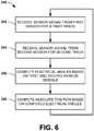
- an example method 300will be better appreciated with reference to FIG. 6 . While, for purposes of simplicity of explanation, the example method 300 of FIG. 6 is shown and described as executing serially, it is to be understood and appreciated that the method is not limited by the illustrated order, as some actions could in other embodiments occur in different orders and/or concurrently from that shown and described herein.
- the method 300 of FIG. 6can be implemented in the context of an encoder system, such as disclosed herein.
- the encoder systemcan employ any encoder technology, such as optical, magnetic and/or mechanical encoder technologies.
- the method of FIG. 6begins at 302 in which a sensor signal is received from a first sensor for a first track that is coupled for rotation with a shaft.
- the sensor signalcan be provided as an analog electrical signal that includes sine and cosine signals corresponding to a complete period over the length of each track element detected by the first sensor as the shaft rotates.
- two sensorsare provided for each track, which sensors are displaced from each other by a predetermined mechanical angle.
- a sensor signalis received from a second sensor for a second track.
- the second trackcan be displaced axially from the first track so as to mitigate interference between tracks and respective sensors.
- At least one of the tracksis configured with a set of track elements exhibiting a nonlinear modulation along a corresponding surface that is facing the respective sensor.
- the nonlinear modulation of such track elementscan be periodic such that one complete period extends along the surface over 360 °m.
- electrical anglescan be computed based on the received sensor signals.
- the electrical anglescan be computed for each sensor position for each track.
- an absolute angular positionis computed based on the computed electrical angles.
- the angular positioncan be computed via an arc tangent function based on reference and quadrature electrical angle values computed from reference and quadrature sensors for each track. The resulting angular position can be stored in memory and utilized for controlling an electrical machine as is known in the art.
- the sensors and calculatorscan be implemented in the analog domain or the digital domain.
- the signalscan also be provided in a variety of forms (e.g., electrical signals, optical signals) having values consistent with its analog or digital implementation. Accordingly, this disclosure is intended to embrace all embodiments, such as including alterations, modifications, and variations that fall within the scope of this application, including the appended claims.
Landscapes
- Physics & Mathematics (AREA)
- General Physics & Mathematics (AREA)
- Transmission And Conversion Of Sensor Element Output (AREA)
Description
- This disclosure relates generally to a system and method to implement an absolute encoder.
- Position detectors are utilized for controlling operation of electrical machines such as motors and generators. There are two main types of encoders: absolute and incremental. As an example, a rotary encoder converts angular position or motion of a shaft to a corresponding analog or digital code. The output of incremental encoders provides information about the motion of the shaft. Absolute rotary encoders are implemented to provide an indication of the current angular position of the shaft. Rotary encoders are used in many applications that require precise and unlimited rotation, such as including industrial controls, robotics, and rotating platforms. Linear encoders are used to encode position along a path. Linear encoders are utilized in metrology instruments (e.g., for semiconductor processing), motion systems and high precision machining tools.
- The document
DE102006060622 discloses a device for detecting the position of a moving component, with at least one encoder moving with the component, which cooperates contactlessly with at least one sensor detecting the position of the sensor. The encoder has detectable marks over its range of motion from the sensor, which have different sizes depending on their positional position. The device has a transmitter that moves with the component. The transmitter works together in a contactless manner with the sensor that detects the position of the transmitter. The transmitter has magnet marks which are detectable over the moving area from the sensor. The characteristic marks have different values as a function of their position. - The present disclosure relates to systems and methods of implementing an absolute encoder. A rotary encoder system and corresponding method according to the present invention are defined in the appended claims.
- In one embodiment, a system can include a plurality of tracks configured to move relative to a longitudinal axis. Each of the plurality of tracks includes a plurality of track elements arranged along each respective track. The plurality of track elements for at least one modulated track of the plurality of tracks is configured with a nonlinear modulation. Two sensors are positioned adjacent to each of the plurality of tracks for detecting the track elements, each given sensor being configured to provide a respective sensor signal corresponding to at least one of position or movement of the respective track elements relative to the given sensor. An indication of absolute position can be computed based on the sensors signals.
- Another embodiment provides a method for determining absolute position. A first sensor signal is received from a first sensor arranged for detecting one of rotation or position of track elements arranged on a first track that is coupled for rotation with a shaft. A second sensor signal is received from a second sensor arranged for detecting one of rotation or position of track elements arranged on a second track that is coupled for rotation with the shaft, the track elements of at least one of the first and second tracks exhibiting a nonlinear modulation along a corresponding surface that is facing the respective sensor. An indication of the absolute angular position of the shaft is computed based on the received first and second sensor signals.
FIG. 1 depicts an example embodiment of an encoder system.FIG. 2 depicts another example embodiment of an encoder system.FIG. 3 depicts yet another example embodiment of an encoder system.FIG. 4 depicts an example of a graph of sensor angle plotted as a function of a mechanical angle according to an example embodiment.FIG. 5 is a graph depicting a modulated track phase relationship in which the sensor angle is plotted as a function of the mechanical angle for reference and quadrature positions according to an example embodiment.FIG. 6 is a flow diagram depicting an example method for determining absolute position.- An absolute encoder is disclosed that includes a plurality (e.g., two or more) of tracks, each having a plurality of track elements. Track elements for at least one of the tracks are configured with a nonlinear modulation. Track elements for at least one other of the tracks can include no modulation. An absolute angular position can be calculated from sensing relative movement of the track elements. For purposes of simplicity of explanation and not by way of limitation, the following example embodiments will be explained in the context of a rotary absolute encoder. However, it will be appreciated that tracks and the modulation scheme could also be implemented as part of an absolute linear encoder based on the teachings herein.
FIG. 1 depicts an example of arotary encoder system 10 that can be implemented. Thesystem 10 includes plurality of (e.g., two or more)tracks tracks axis 15 that extends longitudinally through a rotary shaft, schematically indicated at 16. Thus, each of thetracks axis 15 in a direction, indicated by anarrow 18, which is commensurate with rotation of theshaft 16. It will be understood and appreciated that theshaft 16 can rotate in either direction about theaxis 15. The rotation of theshaft 16, for example, can be caused by a motor or other external source of rotational force that is applied to the shaft, directly or indirectly. The direction and speed of angular rotation of theshaft 16 can vary according to the application requirements.- Each of the
tracks respective track elements FIG. 1 , the surface where thetrack elements respective tracks central axis 15. Thetrack elements track elements tracks track elements corresponding track elements - At least one of the sets of track elements is modulated relative to the other set of track elements by a nonlinear modulation. As an example, each of the
tracks track elements track elements 22 can be modulated nonlinearly in a predetermined manner (e.g., one modulation period) over one mechanical revolution (360 °m). That is, thetrack elements 22 on themodulated track 14 have a circumferential dimension (e.g., arc length) that varies with respect to the corresponding dimensions oftrack elements 20 in thetrack 12 in a nonlinear manner. The nonlinear modulation can be implemented such that the track elements are initially synchronized (e.g., at 0 °m) then, as theshaft 16 rotates, the modulation varies the circumferential dimension of thetrack elements 22 nonlinearly over a complete mechanical revolution (i.e., 360 °m) until the shaft has rotated back to 0 °m. - As a further example of a modulation scheme, the
track elements tracks track elements 20 can be implemented with a sinusoidal modulation and theother track elements 22 can be implemented with a cosinusoidal modulation, each synchronized with respect to a mechanical starting point (e.g., corresponding to 0 °m). Each of thetracks - In order to detect the modulation of the
track elements system 10 includes two sensors positioned adjacent to each of thetracks shaft 16. - In the example of
FIG. 1 ,sensors track elements 20 of thetrack 12. Similarly,sensors elements 22 of thetrack 14, and are also arranged in a quadrature relationship, and are configured for sensing the track elements. While the sensor pairs 24, 26 and 28, 30 are demonstrated as being angularly displaced by 90 °m, it will be appreciated that other angular relationships (e.g., 30 °m, 60 °m, 120 °m or the like) can be implemented between each respective sensor pair on eachtrack sensors reference sensors sensors system 10. Each of thesensors respective track elements - The
track elements sensors sensors track elements - As an example, the
track elements track elements shaft 16. Alternatively, the magnets can be affixed directly on a surface of theshaft 16. The arc length (e.g., radially outer extent) of each pole (e.g., track element) that is adjacent torespective sensors sensors surface track elements sensors - By way of further example, the
track elements track elements sensors - As yet another example, the
track elements corresponding sensors sensors track elements shaft 16 or circumferential structure attached around the shaft. Alternatively, the optical track elements can be implemented as alternating reflective and non-reflective elements on the surface of the shaft. Another type of optical encoder technology employs slits that can be formed along the circumference of a metal or glass disc onto which a beam of light is provided. - Regardless of the technology utilized to implement the
track elements sensors calculator 32. Thecalculator 32 is configured to determine an absolute angle of rotation for the shaft based on the sensor signals. Thecalculator 32 can be implemented as hardware (e.g., analog circuitry and/or digital circuitry, such as an arithmetic logic unit (ALU)), software (e.g., computer executable instructions executed by a processor), or as a combination of hardware and software configured to compute an absolute angular position based on the information provided by the sensors. The calculator thus provides means for computing an indication of absolute position. The computations performed by thecalculator 32 will vary depending on the nonlinear modulation implemented in the respective tracks and whether one or more of the tracks employs such non-linear modulation. - The
calculator 32 can provide the angle in any desired format, such as according to a known protocol, including any one or more public, proprietary or yet to be developed protocols. Some examples of protocols that thecalculator 32 can implement include parallel binary, Synchronous Serial Interface (SSI), "BiSS" (published as an open source protocol by iC-Haus GmbH of Bodenheim, Germany), 151, Profibus (Process Field Bus), Controller Area Network (CAN), DeviceNet, CANopen, Endat, and Hiperface. Thecalculator 32 can be selectively programmed (e.g., in response to a user input) to provide its output in a format according to any of such protocols. - As a further example, analog-to-digital converters can convert the sensor signals to corresponding digital signals having respective digital codes (e.g., values). The
calculator 32 can be programmed and/or configured to compute an electrical angle based on the sensor signal detected for each of the respective track elements. Because the relative modulation is known and quantifiable mathematically, thecalculator 32 can aggregate the computed electrical angles to determine an absolute angular position of the shaft (e.g., a mechanical angle). Thus, the angular position can be provided as a substantially real time output signal. Thecalculator 32 thus can determine the absolute angular position of theshaft 16 without having to employ an absolute reference marker for detecting an absolute position. FIG. 2 depicts another example of anencoder system 50 not forming part of the present invention. Thesystem 50 is configured to determine an absolute angular position of ashaft 58 that can rotate in adirection 60 about itslongitudinal axis 55. Theexample system 50 ofFIG. 2 is similar in configuration to thesystem 10 ofFIG. 1 but includes threetracks tracks respective track elements track elements - In the example of
FIG. 2 , two or more of thetrack elements nonmodulated track elements 62 while the other tracks include sets oftrack elements track elements track elements track elements respective tracks - A
sensor track elements respective tracks sensors shaft 58. Thesensors track elements tracks track elements - The sensors signals can be digitized and provided to a
calculator 74 that is programmed to compute an indication of the angular position of the shaft based on the information provided by the sensor signals. That is, each of thesensors axis 55. For example, each of thetrack elements track elements 62 of theother track 52, being reference track, can be non-modulated. Since the modulation of thetrack elements non-modulated track elements 62, which relative modulation can be quantified (e.g., as a constant or variable), thecalculator 74 can be preprogrammed to compute the angular position of theshaft 58 based on the sensor signals, such as disclosed herein. - Those skilled in the art will understand and appreciate that the calculations can further vary depending on the type of encoder technology being utilized and the particular modulation that is implemented in each of the tracks. It will be understood that with the addition of another track in the example of
FIG. 2 (as compared to the example ofFIG. 1 ), an additional sensor can be omitted from each of the tracks yet still compute an indication of absolute angular position. Thus, the cost of implementing more tracks (e.g., in the example ofFIG. 2 ) or more sensors (e.g., in the example ofFIG. 1 ) can be balanced to determine a desirable configuration for a given application. - By way of further example,
FIG. 3 depicts an example of anencoder system 100 implemented as a magnetic rotary through-bore or hollow-shaft encoder. As described herein, the architecture and functionality demonstrated with respect toFIG. 3 is applicable to various types of encoder technologies, including other types of magnetic encoders, optical encoders, and mechanical encoders. - In the example of
FIG. 3 , thesystem 100 includesannular tracks rotary shaft 106 that can rotate about anaxis 107 in a direction, indicated at 108. Thetrack 102 includes a set oftrack elements 110 arranged circumferentially about theaxis 107. Thetrack 104 also includes a set oftrack elements 112 arranged circumferentially about theaxis 107. In the example ofFIG. 3 , thetrack elements 110 can be considered "pure" since they have constant size and thus no modulation. Thetrack elements 112 of theother track 104 are modulated nonlinearly in their circumferential configuration, such as according to a sinusoidal or cosinusoidal function. Other types of nonlinear modulation can also be utilized for thetrack elements 112. - As an example, the
track 102 can be implemented as a standard incremental encoder magnetic track in which thetrack elements 110 consist of a predetermined number (N) of magnetic poles. As mentioned above, in this example, it is assumed that the magnetic poles forming thetrack elements 110 are not modulated. That is, each pole has the same arc length. Theother track 104 can be configured similarly in that it has the same number (N) oftrack elements 112 implemented as magnetic poles like thetrack 102, but the magnetic poles forming itstrack elements 112 are nonlinearly modulated. This nonlinear modulation causes the alignment of the poles on the modulatedtrack 104 to vary relative to the poles on thenon-modulated track 102 as theshaft 106 rotates about itsaxis 107. For example, the modulation can be implemented such that thetrack elements 112 in the modulated track vary relative to thetrack elements 110 in the pure track in a sinusoidal manner over one period for each mechanical revolution (360 °m). - In the example of
FIG. 3 , thesystem 100 also includessensors track elements MR sensors track sensors shaft 106 at a given reference (R) position(e.g., corresponding to 0° mechanical,i.e., 0°m). Theother sensors references sensors sensors - The
system 100 also includes hardware and/or software to compute the angular position of theshaft 106 based on the sensor signals provided by therespective sensors FIG. 3 , thesensors respective calculators calculator respective track respective calculators calculators track element respective sensors - The
calculators FIG. 3 , each of thecalculators digital converters 130 configured to convert the analog sensor output signals Vs and Vc(e.g., analog electrical signals) to a digital representation thereof. Correction blocks 132 can adjust (e.g., by implementing offset and/or gain compensation) each of digital sensor output signals Vs and Vc. While correction blocks 132 are demonstrated for each sensor signal channel, it will be appreciated that the correction can be performed on a comparative basis based on the characteristics of the sensors signals Vs and Vc for eachsensor correction block 132 can further normalize the pair of sensor signals relative to each other to facilitate the computing an electrical (pole) angle for a given track element. Those skilled in the art will appreciate various types of correction that can be implemented via the corrections blocks to compensate for errors and variations in sensor circuitry and other noise that may exist in practical applications to facilitate calculating the electrical angles for eachsensor - Each of the
calculators ALU 134 can be implemented as digital circuitry and/or logic configured to perform a predetermined mathematical operation, such as an arc tangent function, based on the digitized and corrected sensor signals. Thus, each of thecalculators shaft 106. - In the example of
FIG. 3 , the outputs of each of thecalculators track 102 as sensed by the reference (R)sensor 114, ΦMQ is the polar angle of the modulated (M)track 104 as sensed by the quadrature (Q)sensor 120, etc. - In view of the foregoing nomenclature, ifθ is the mechanical angle of rotation (measured in radians) of the two
tracks common axis 107, then the output of the calculators (e.g., performing an arc tangent operation) 122, 124, 126 and 128 can be expressed as follows:


track 104 relative to thenon-modulated track 102. FIG. 4 is agraph 200 demonstrating the relationship between sensor angle representing the electrical angle for each pole (denoted °p) and the mechanical angle of the shaft (denoted °m), such as can be provided by the calculators described with respect toFIG. 3 . Theexample graph 200 ofFIG. 4 demonstrates the relationship between the output of a reference sensor for a non-modulated track, indicated at 202 via dotted lines, and the output of a sensor for a modulated track, indicated at 204. Theplot 202 for the non-modulated track includes evenly spaced cycles over a complete mechanical revolution (360°m) of the shaft. By comparison, theplot 204 for the modulated track exhibits the same number of cycles over 360°m, however, these cycles are not evenly spaced. The spacing of the cycles in theplot 204 for the modulated track corresponds to the nonlinear modulation in the spacing of the track elements (e.g., magnetic poles) detected by the sensor. In the example modulation, the modulated track output leads the non-modulated track output over the first half of the revolution (e.g., from 0°m to 180°m), and lags the pure track output over the second half of the revolution (e.g., from 180°m to 360°m) due to the nonlinearly modulated track elements (e.g., having sinusoidal modulation). Other forms of non-linear modulation would provide for different relationships between sensor signals. Thus, for each given mechanical revolution, each of the sensors provides the same number of cycles, but the cycles are incrementally different according to the nonlinear modulation implemented for the track elements on the modulated track.- As mentioned above, the
example graph 200 demonstrates the relationship between outputs of reference sensors in an encoder system. The same sort of relationship exists for the quadrature sensors for each of the non-modulated and modulated tracks. However, due to the quadrature positioning of such sensors (e.g., being arranged 90°m relative to the reference sensors), the modulation exhibits a cosinusoidal characteristic. While the example inFIG. 4 demonstrates sensor outputs for twelve pole tracks, those skilled in the art will understand and appreciate that any number of poles (greater or lesser than twelve) can be utilized. - Returning to the example of
FIG. 3 , thesystem 100 is configured to perform additional mathematical operations for use in deriving the angular position of theshaft 106. For instance, thesystem 100 employsrespective difference components difference component difference components difference components output calculator 140. - For example, from Equations 1-4, the relative modulation for each of the reference (R) and quadrature (Q) positions, which can be computed by
difference components 

- An example relationship in the modulation of the modulated track as sensed by the sensor pair at the reference and quadrature positions is demonstrated in
graph 250 inFIG. 5 . In the example ofFIG. 5 , thegraph 250 demonstrates afirst waveform 252, such as derived from the signals provided by sensors at the reference position (e.g., ΦR), and asecond waveform 254, such as derived from the sensors at the quadrature position (e.g., ΦQ). - The
output calculator 140 is configured to compute an absolute angular position Φ of theshaft 106 as a function of the outputs from thesubtractor components electrical angle calculators output calculator 140 can include acorrection block 142 that is configured to correct errors in the respective reference and quadrature signals provided by the difference components blocks 136 and 138. For instance the correction block can normalize the signals ΦR and ΦQ (e.g., via phase and amplitude adjustments) relative to each other. AnALU 144 is configured to compute the angle Φ of theshaft 106 based on the corrected reference and quadrature signals. As an example, theALU 144 can be configured to perform an arctangent calculation such as follows:
- The calculated angle can be utilized depending on the type of system 100 (e.g., a motor or generator). By way of example, the resulting angle value determined by the
calculator 140 can be stored as angle data inmemory 146, such as a buffer, a register or other memory structure that may be utilized in thesystem 100. The corresponding angle data can be utilized by acontrol system 148, such as for controlling operation of an electrical machine (e.g., a motor or generator), schematically indicated at 150. Theelectrical machine 150 can be connected to theshaft 106, directly or indirectly. Those skilled in the art will understand and appreciate various configurations that can be utilized for thecontrol system 148, which can vary depending on the electrical machine that is implemented. Thecontrol system 148 can include a microcontroller (e.g., analog and/or digital circuitry, such an ASIC or microprocessor) and/or switching network for controlling power provided to or from theelectrical machine 150. Thus, thecontrol system 148 may provide means for controlling operation of an electrical machine based on the indication of absolute position. - Additionally, the
calculator 140 further can provide the absolute angular position Φ for transmission and use by the control system according to a desired communication protocol. Alternatively, thesystem 100 can employ a converter that can be programmed to convert the output angle from thecalculator 140 to a desired format, which can be selected in response to a user input. Some examples of known communication protocols in which the calculator 140 (or associated converter (not shown)) can be provide the angular position include parallel binary, SSI, "BiSS", ISI, Profibus, CAN, DeviceNet, CANopen, Endat and Hiperface. Other known and yet-to-be developed communication protocols can also be utilized. - In view of the foregoing structural and functional features described above, an
example method 300 will be better appreciated with reference toFIG. 6 . While, for purposes of simplicity of explanation, theexample method 300 ofFIG. 6 is shown and described as executing serially, it is to be understood and appreciated that the method is not limited by the illustrated order, as some actions could in other embodiments occur in different orders and/or concurrently from that shown and described herein. - The
method 300 ofFIG. 6 can be implemented in the context of an encoder system, such as disclosed herein. For example, the encoder system can employ any encoder technology, such as optical, magnetic and/or mechanical encoder technologies. The method ofFIG. 6 begins at 302 in which a sensor signal is received from a first sensor for a first track that is coupled for rotation with a shaft. As an example, the sensor signal can be provided as an analog electrical signal that includes sine and cosine signals corresponding to a complete period over the length of each track element detected by the first sensor as the shaft rotates. In some embodiments, two sensors are provided for each track, which sensors are displaced from each other by a predetermined mechanical angle. - At 304, a sensor signal is received from a second sensor for a second track. The second track can be displaced axially from the first track so as to mitigate interference between tracks and respective sensors. At least one of the tracks is configured with a set of track elements exhibiting a nonlinear modulation along a corresponding surface that is facing the respective sensor. The nonlinear modulation of such track elements, for example, can be periodic such that one complete period extends along the surface over 360 °m.
- At 306, electrical angles can be computed based on the received sensor signals. As disclosed herein, in the example where multiple sensors (e.g., reference and quadrature sensors) are implemented for each track, the electrical angles can be computed for each sensor position for each track. At 308, an absolute angular position is computed based on the computed electrical angles. As an example, the angular position can be computed via an arc tangent function based on reference and quadrature electrical angle values computed from reference and quadrature sensors for each track. The resulting angular position can be stored in memory and utilized for controlling an electrical machine as is known in the art.
- What has been described above are example embodiments. It is, of course, not possible to describe every conceivable embodiment, but one of ordinary skill in the art will recognize that other embodiments are possible. For example, the sensors and calculators can be implemented in the analog domain or the digital domain. The signals can also be provided in a variety of forms (e.g., electrical signals, optical signals) having values consistent with its analog or digital implementation. Accordingly, this disclosure is intended to embrace all embodiments, such as including alterations, modifications, and variations that fall within the scope of this application, including the appended claims. Additionally, where the disclosure or claims recite "a," "an," "a first," or "another" element, or the equivalent thereof, it should be interpreted to include one or more than one such element, neither requiring nor excluding two or more such elements. As used herein, the term "includes" means includes but not limited to, the term "including" means including but not limited to. The term "based on" means based at least in part on.


Claims (7)
- A rotary encoder system (10), comprising:a plurality of tracks (12, 14) fixed to a rotary shaft (16) that is configured to rotate circumferentially about a longitudinal axis (15) of the shaft (16), each of the plurality of tracks (12, 14) comprising a set of track elements (20, 22) arranged continuously along a circumferential surface of each respective track (12, 14), the track elements of at least one of the sets of track elements (20, 22) are modulated non-uniformly along the track, and the track elements of the at least one of the sets of track elements (20) and the other set of track elements (22) are modulated differently, each of the set of track elements (22) for the at least one modulated track of the plurality of tracks (14) having a circumferential length that varies along the circumferential surface of the at least one modulated track to provide the at least one modulated track with a nonlinear modulation along the at least one modulated track; andfor each of the plurality of tracks, the rotary encoder system comprises two sensors (24, 26; 28, 30) positioned adjacent to the corresponding track, a reference sensor (24, 28) located at a reference angular position and a second sensor (26, 30) located at an angular position that is angularly shifted relative to the corresponding reference angular position by a predetermined mechanical angle, each given sensor being configured to provide a respective sensor signal, each of the sensors (24, 26, 28 and 30) being arranged for sensing position or movement of the respective set of track elements (20, 22) and for providing respective sensor signals representing position or movement of the track elements (20, 22), wherein the at least one sensor (28, 30) positioned adjacent to the at least one nonlinearly modulated track (14) is configured to provide a sensor signal that varies according to the circumferential_length of each respective track element of the set of track elements of the at least one modulated track (14) such that the sensor signal completes a period as each of track elements is rotated past the sensor according to the circumferential_length of each respective track element to thereby encode the nonlinear modulation along the respective track, each respective sensor signal being outputted to a calculator (32),wherein
for each of the plurality of tracks, the calculator (32) is configured to compute a reference electrical angle from the signal of the reference sensor (24, 28) and a second electrical angle from the signal of the second sensor (26, 30), and to compute an indication of the absolute rotational position of the rotary shaft (16) based on said reference electrical angles and second electrical angles. - The system of claim 1,
wherein the track elements for each of the plurality of tracks are alternating magnetic poles configured circumferentially along the surface of its respective track. - The system of claim 1, wherein the calculator further comprises:a first calculator to compute the electrical angle for each track element detected by each of the plurality of sensors; anda second calculator to compute the indication of the absolute rotational position of the rotary shaft (16) based on the electrical angles computed by the first calculator.
- The system of claim 3, further comprising
a difference component operative to compute a difference between a pair of the second electrical angles; and
a reference difference component to compute a difference between a pair of the reference electrical angles, the indication of absolute rotational position being determined based on the computed differences. - The system of claim 1, further comprising a control system configured to control operation of an electrical machine based on the indication of absolute rotational position, the electrical machine being coupled to the shaft.
- The system of claim 1, wherein each of the track elements comprises one of an optical pattern, a mechanical pattern or magnetic poles.
- The system of claim 1,
wherein the nonlinear modulation comprises a sinusoidal modulation,
wherein the circumferential length of the track elements in the modulated track decreases in length over a first angular portion of the modulated track and then increases in length over a next angular portion thereof to provide nonlinear modulation over one mechanical period.
Applications Claiming Priority (2)
| Application Number | Priority Date | Filing Date | Title |
|---|---|---|---|
| US32791610P | 2010-04-26 | 2010-04-26 | |
| PCT/US2011/033919WO2011139682A2 (en) | 2010-04-26 | 2011-04-26 | Absolute encoder |
Publications (3)
| Publication Number | Publication Date |
|---|---|
| EP2564165A2 EP2564165A2 (en) | 2013-03-06 |
| EP2564165A4 EP2564165A4 (en) | 2015-05-27 |
| EP2564165B1true EP2564165B1 (en) | 2019-06-12 |
Family
ID=44815267
Family Applications (1)
| Application Number | Title | Priority Date | Filing Date |
|---|---|---|---|
| EP11777908.2AActiveEP2564165B1 (en) | 2010-04-26 | 2011-04-26 | Absolute encoder |
Country Status (4)
| Country | Link |
|---|---|
| US (1) | US8723511B2 (en) |
| EP (1) | EP2564165B1 (en) |
| ES (1) | ES2732551T3 (en) |
| WO (1) | WO2011139682A2 (en) |
Families Citing this family (41)
| Publication number | Priority date | Publication date | Assignee | Title |
|---|---|---|---|---|
| US9217731B2 (en) | 2010-05-21 | 2015-12-22 | Kabushiki Kaisha Toshiba | Welding inspection method and apparatus thereof |
| US20110284508A1 (en)* | 2010-05-21 | 2011-11-24 | Kabushiki Kaisha Toshiba | Welding system and welding method |
| JP5393598B2 (en)* | 2010-06-03 | 2014-01-22 | キヤノン株式会社 | Galvano device and laser processing device |
| JP5379761B2 (en)* | 2010-08-06 | 2013-12-25 | キヤノン株式会社 | Absolute encoder |
| US9359794B2 (en) | 2014-03-12 | 2016-06-07 | August Home, Inc. | Method for operating an intelligent door knob |
| US10388094B2 (en) | 2013-03-15 | 2019-08-20 | August Home Inc. | Intelligent door lock system with notification to user regarding battery status |
| US9326094B2 (en) | 2013-03-15 | 2016-04-26 | August Home, Inc. | BLE/WiFi bridge with audio sensor |
| US11441332B2 (en) | 2013-03-15 | 2022-09-13 | August Home, Inc. | Mesh of cameras communicating with each other to follow a delivery agent within a dwelling |
| US11802422B2 (en) | 2013-03-15 | 2023-10-31 | August Home, Inc. | Video recording triggered by a smart lock device |
| US11527121B2 (en) | 2013-03-15 | 2022-12-13 | August Home, Inc. | Door lock system with contact sensor |
| US9382739B1 (en) | 2013-03-15 | 2016-07-05 | August Home, Inc. | Determining right or left hand side door installation |
| US9706365B2 (en) | 2013-03-15 | 2017-07-11 | August Home, Inc. | BLE/WiFi bridge that detects signal strength of bluetooth LE devices at an interior of a dwelling |
| US10443266B2 (en) | 2013-03-15 | 2019-10-15 | August Home, Inc. | Intelligent door lock system with manual operation and push notification |
| US10140828B2 (en) | 2015-06-04 | 2018-11-27 | August Home, Inc. | Intelligent door lock system with camera and motion detector |
| US9528294B2 (en) | 2013-03-15 | 2016-12-27 | August Home, Inc. | Intelligent door lock system with a torque limitor |
| US9574372B2 (en) | 2013-03-15 | 2017-02-21 | August Home, Inc. | Intelligent door lock system that minimizes inertia applied to components |
| US11043055B2 (en) | 2013-03-15 | 2021-06-22 | August Home, Inc. | Door lock system with contact sensor |
| US11072945B2 (en) | 2013-03-15 | 2021-07-27 | August Home, Inc. | Video recording triggered by a smart lock device |
| US9447609B2 (en) | 2013-03-15 | 2016-09-20 | August Home, Inc. | Mobile device that detects tappings/vibrations which are used to lock or unlock a door |
| US11352812B2 (en) | 2013-03-15 | 2022-06-07 | August Home, Inc. | Door lock system coupled to an image capture device |
| US9818247B2 (en) | 2015-06-05 | 2017-11-14 | August Home, Inc. | Intelligent door lock system with keypad |
| US9725927B1 (en) | 2014-03-12 | 2017-08-08 | August Home, Inc. | System for intelligent door knob (handle) |
| US9528296B1 (en) | 2013-03-15 | 2016-12-27 | August Home, Inc. | Off center drive mechanism for thumb turning lock system for intelligent door system |
| US9704314B2 (en) | 2014-08-13 | 2017-07-11 | August Home, Inc. | BLE/WiFi bridge that detects signal strength of Bluetooth LE devices at an exterior of a dwelling |
| US11421445B2 (en) | 2013-03-15 | 2022-08-23 | August Home, Inc. | Smart lock device with near field communication |
| US9695616B2 (en) | 2013-03-15 | 2017-07-04 | August Home, Inc. | Intelligent door lock system and vibration/tapping sensing device to lock or unlock a door |
| US10181232B2 (en) | 2013-03-15 | 2019-01-15 | August Home, Inc. | Wireless access control system and methods for intelligent door lock system |
| US10691953B2 (en) | 2013-03-15 | 2020-06-23 | August Home, Inc. | Door lock system with one or more virtual fences |
| US9922481B2 (en) | 2014-03-12 | 2018-03-20 | August Home, Inc. | Intelligent door lock system with third party secured access to a dwelling |
| US9916746B2 (en) | 2013-03-15 | 2018-03-13 | August Home, Inc. | Security system coupled to a door lock system |
| JP6310189B2 (en)* | 2013-05-29 | 2018-04-11 | Dmg森精機株式会社 | Correction method of rotation angle command value |
| KR102224756B1 (en) | 2013-11-13 | 2021-03-08 | 브룩스 오토메이션 인코퍼레이티드 | Sealed robot drive |
| JP2016537948A (en) | 2013-11-13 | 2016-12-01 | ブルックス オートメーション インコーポレイテッド | Sealed switched reluctance motor |
| TWI695447B (en) | 2013-11-13 | 2020-06-01 | 布魯克斯自動機械公司 | Transport apparatus |
| KR102383699B1 (en) | 2013-11-13 | 2022-04-06 | 브룩스 오토메이션 인코퍼레이티드 | Method and apparatus for brushless electrical machine control |
| EP3080555B1 (en)* | 2013-12-13 | 2018-01-17 | Schaeffler Technologies AG & Co. KG | Device for and method of measuring a rotor parameter |
| US11933641B2 (en)* | 2020-01-15 | 2024-03-19 | Honeywell International Inc. | Position detection apparatus, method, and system utilizing an array of magnetic sensors each comprising a sensor signal conditioning circuit |
| CN116457545A (en) | 2020-09-17 | 2023-07-18 | 亚萨合莱股份有限公司 | Magnetic sensor for lock position |
| JP2023543236A (en) | 2020-09-25 | 2023-10-13 | アッサ・アブロイ・インコーポレイテッド | door lock with magnetometer |
| JP2023543572A (en) | 2020-09-25 | 2023-10-17 | アッサ・アブロイ・インコーポレイテッド | multidirectional door lock |
| KR102591233B1 (en)* | 2021-02-25 | 2023-10-20 | 에스티엠(주) | Magnetic encoder |
Citations (3)
| Publication number | Priority date | Publication date | Assignee | Title |
|---|---|---|---|---|
| DE102006060622A1 (en)* | 2006-12-21 | 2008-06-26 | Robert Bosch Gmbh | Device for position detection of moving component, has transmitter that moves with component, and transmitter works together in contactless manner with sensor that detects position of transmitter |
| US20090271998A1 (en)* | 2008-05-02 | 2009-11-05 | Carlen Controls, Inc. | Linear Position Transducer With Wireless Read Head |
| US20090284252A1 (en)* | 2004-09-30 | 2009-11-19 | Continental Teves Ag & Co. Ohg | Device for measuring the absolute position of at least two members that are movable or rotatable relative to each other |
Family Cites Families (23)
| Publication number | Priority date | Publication date | Assignee | Title |
|---|---|---|---|---|
| JPS57175211A (en)* | 1981-04-23 | 1982-10-28 | Hitachi Constr Mach Co Ltd | Angle detector of rotating body |
| JPH01297507A (en)* | 1988-05-26 | 1989-11-30 | Hitachi Ltd | Device that magnetically detects position and speed |
| US5506579A (en)* | 1991-06-06 | 1996-04-09 | Trj & Company | Absolute encoder using multiphase analog signals |
| DE4407474C2 (en) | 1994-03-07 | 2000-07-13 | Asm Automation Sensorik Messte | Angle of rotation sensor |
| JP2626609B2 (en)* | 1994-12-12 | 1997-07-02 | 日本電気株式会社 | Rotary encoder and rotary disk used for this rotary encoder |
| EP0790489B1 (en) | 1996-02-16 | 2000-05-17 | Dr. Johannes Heidenhain GmbH | Apparatus and method for switching between different operating characteristics of a sensor device |
| US6232594B1 (en)* | 1999-06-22 | 2001-05-15 | Hewlett-Packard Company | Feedback control system using optical incremental position encoder with dual sinusoidal intensity patterns |
| DE19962278A1 (en) | 1999-12-23 | 2001-08-02 | Heidenhain Gmbh Dr Johannes | Position measuring device |
| EP1126248B2 (en) | 2000-02-17 | 2012-10-17 | Dr. Johannes Heidenhain GmbH | Position measuring device as well as method for operating the same |
| FR2811077B1 (en)* | 2000-06-30 | 2002-09-13 | Roulements Soc Nouvelle | DEVICE FOR DETERMINING THE ABSOLUTE ANGULAR POSITION OF A ROTATING MEMBER |
| DE60223898T2 (en)* | 2002-01-30 | 2008-11-27 | Continental Automotive Gmbh | Method and device for determining the rotor position of a motor by feeding a resolver signal derived from the rotor position into a single control system which serves both to trigger and to determine the resolver signal, and to a motorized vehicle equipped with such a device is |
| US7301031B2 (en) | 2002-09-09 | 2007-11-27 | Biocatalytics, Inc. | Methods for producing hydroxy amino acids, esters, and derivatives thereof |
| DE10254897A1 (en) | 2002-11-20 | 2004-06-03 | Dr. Johannes Heidenhain Gmbh | Measuring graduation for a position measuring system |
| JP2004257850A (en)* | 2003-02-26 | 2004-09-16 | Fanuc Ltd | Rotary encoder |
| JP2004333156A (en) | 2003-04-30 | 2004-11-25 | Harmonic Drive Syst Ind Co Ltd | Encoder signal interpolation divider |
| US7045769B2 (en) | 2003-10-29 | 2006-05-16 | The Boeing Company | Optical encoders for position measurements |
| CN100516780C (en) | 2003-11-17 | 2009-07-22 | Gsi集团公司 | Absolute encoder using cascaded multi-bit interpolating sub-encoders |
| DE102004062278A1 (en)* | 2004-12-23 | 2006-07-13 | Siemens Ag | Measuring element and measuring method with a track for determining a position |
| EP1715298B1 (en) | 2005-04-19 | 2017-07-19 | Mitutoyo Corporation | Absolute rotary encoder and micrometer |
| JP4673757B2 (en)* | 2006-01-23 | 2011-04-20 | 株式会社東海理化電機製作所 | Rotation angle detector |
| DE102007008870A1 (en) | 2007-02-21 | 2008-09-04 | Hl-Planar Technik Gmbh | Arrangement and method for the absolute determination of the linear position or the angular position expressed by an angle |
| CN101646922B (en)* | 2007-04-24 | 2011-06-22 | 谐波传动系统有限公司 | Absolute Rotational Position Detection Method |
| US7999536B2 (en)* | 2007-10-22 | 2011-08-16 | The Timken Company | Absolute position magnetic encoder with binary and decimal output |
- 2011
- 2011-04-26EPEP11777908.2Apatent/EP2564165B1/enactiveActive
- 2011-04-26ESES11777908Tpatent/ES2732551T3/enactiveActive
- 2011-04-26USUS13/094,355patent/US8723511B2/enactiveActive
- 2011-04-26WOPCT/US2011/033919patent/WO2011139682A2/enactiveApplication Filing
Patent Citations (3)
| Publication number | Priority date | Publication date | Assignee | Title |
|---|---|---|---|---|
| US20090284252A1 (en)* | 2004-09-30 | 2009-11-19 | Continental Teves Ag & Co. Ohg | Device for measuring the absolute position of at least two members that are movable or rotatable relative to each other |
| DE102006060622A1 (en)* | 2006-12-21 | 2008-06-26 | Robert Bosch Gmbh | Device for position detection of moving component, has transmitter that moves with component, and transmitter works together in contactless manner with sensor that detects position of transmitter |
| US20090271998A1 (en)* | 2008-05-02 | 2009-11-05 | Carlen Controls, Inc. | Linear Position Transducer With Wireless Read Head |
Also Published As
| Publication number | Publication date |
|---|---|
| EP2564165A4 (en) | 2015-05-27 |
| ES2732551T3 (en) | 2019-11-25 |
| US8723511B2 (en) | 2014-05-13 |
| WO2011139682A2 (en) | 2011-11-10 |
| WO2011139682A3 (en) | 2012-02-23 |
| EP2564165A2 (en) | 2013-03-06 |
| US20110260716A1 (en) | 2011-10-27 |
Similar Documents
| Publication | Publication Date | Title |
|---|---|---|
| EP2564165B1 (en) | Absolute encoder | |
| US7875844B2 (en) | Absolute-type encoder and method for detecting absolute position | |
| CN108592956B (en) | Rotary encoder and absolute angle position detection method thereof | |
| US11733260B2 (en) | Angle based speed sensor device | |
| KR101218028B1 (en) | Rotation angle detection apparatus | |
| EP2962070B1 (en) | Angle sensor, a bearing unit, electrical motor, a control system and error-check system | |
| KR101502259B1 (en) | Device for detecting multi-turn absolute rotation angle, and method for detecting rotation angle thereof | |
| US10613113B2 (en) | Position detecting device | |
| US20140347040A1 (en) | Rotation-angle detection device, image processing apparatus, and rotation-angle detection method | |
| CN101571409B (en) | Absolute Encoder and Its Method of Detecting Absolute Position | |
| CN102506905B (en) | A kind of High Precision Absolute Encoder | |
| JP2018132356A (en) | Rotary encoder | |
| CN112117079B (en) | Encoder magnet structure, encoder, motor, electrical equipment and vehicle | |
| KR20170106209A (en) | Rotary encoder and angle correction method of rotary encoder | |
| CN105424063A (en) | Absolute position monitoring system and method | |
| TW201009303A (en) | Absolute-type encoder and method for detecting absolute position | |
| JP2018132357A (en) | Rotary encoder | |
| US20050002032A1 (en) | Non-contact optical polarization angle encoder | |
| US7321113B2 (en) | Precision material-handling robot employing high-resolution, compact absolute encoder | |
| EP3663724B1 (en) | Absolute rotary encoder and apparatus | |
| JP2014070977A (en) | Encoder, and abnormality detection method of encoder | |
| KR102228615B1 (en) | Position detecting device | |
| JP2001050774A (en) | Sine cosine output sensor and servo motor using the same | |
| WO2004102225A2 (en) | Non-contact optical polarization angle encoder | |
| WO2003040662A1 (en) | Non-contact optical polarization angle encoder |
Legal Events
| Date | Code | Title | Description |
|---|---|---|---|
| PUAI | Public reference made under article 153(3) epc to a published international application that has entered the european phase | Free format text:ORIGINAL CODE: 0009012 | |
| 17P | Request for examination filed | Effective date:20121025 | |
| AK | Designated contracting states | Kind code of ref document:A2 Designated state(s):AL AT BE BG CH CY CZ DE DK EE ES FI FR GB GR HR HU IE IS IT LI LT LU LV MC MK MT NL NO PL PT RO RS SE SI SK SM TR | |
| DAX | Request for extension of the european patent (deleted) | ||
| RAP1 | Party data changed (applicant data changed or rights of an application transferred) | Owner name:NIDEC AVTRON AUTOMATION CORPORATION | |
| A4 | Supplementary search report drawn up and despatched | Effective date:20150430 | |
| RIC1 | Information provided on ipc code assigned before grant | Ipc:G01D 5/12 20060101ALI20150423BHEP Ipc:G01D 5/244 20060101AFI20150423BHEP Ipc:G01D 5/249 20060101ALI20150423BHEP Ipc:G01D 5/245 20060101ALI20150423BHEP Ipc:G01D 5/347 20060101ALI20150423BHEP | |
| RIC1 | Information provided on ipc code assigned before grant | Ipc:G01D 5/347 20060101ALI20150720BHEP Ipc:G01D 5/12 20060101ALI20150720BHEP Ipc:G01D 5/245 20060101ALI20150720BHEP Ipc:G01D 5/244 20060101AFI20150720BHEP Ipc:G01D 5/249 20060101ALI20150720BHEP | |
| STAA | Information on the status of an ep patent application or granted ep patent | Free format text:STATUS: EXAMINATION IS IN PROGRESS | |
| 17Q | First examination report despatched | Effective date:20171113 | |
| REG | Reference to a national code | Ref country code:DE Ref legal event code:R079 Ref document number:602011059677 Country of ref document:DE Free format text:PREVIOUS MAIN CLASS: G01D0005244000 Ipc:G01D0005245000 | |
| GRAP | Despatch of communication of intention to grant a patent | Free format text:ORIGINAL CODE: EPIDOSNIGR1 | |
| STAA | Information on the status of an ep patent application or granted ep patent | Free format text:STATUS: GRANT OF PATENT IS INTENDED | |
| RIC1 | Information provided on ipc code assigned before grant | Ipc:G01D 5/245 20060101AFI20190121BHEP Ipc:G01D 5/347 20060101ALI20190121BHEP | |
| INTG | Intention to grant announced | Effective date:20190206 | |
| GRAS | Grant fee paid | Free format text:ORIGINAL CODE: EPIDOSNIGR3 | |
| GRAA | (expected) grant | Free format text:ORIGINAL CODE: 0009210 | |
| STAA | Information on the status of an ep patent application or granted ep patent | Free format text:STATUS: THE PATENT HAS BEEN GRANTED | |
| AK | Designated contracting states | Kind code of ref document:B1 Designated state(s):AL AT BE BG CH CY CZ DE DK EE ES FI FR GB GR HR HU IE IS IT LI LT LU LV MC MK MT NL NO PL PT RO RS SE SI SK SM TR | |
| REG | Reference to a national code | Ref country code:GB Ref legal event code:FG4D | |
| REG | Reference to a national code | Ref country code:CH Ref legal event code:EP | |
| REG | Reference to a national code | Ref country code:AT Ref legal event code:REF Ref document number:1143150 Country of ref document:AT Kind code of ref document:T Effective date:20190615 | |
| REG | Reference to a national code | Ref country code:NL Ref legal event code:FP Ref country code:IE Ref legal event code:FG4D | |
| REG | Reference to a national code | Ref country code:DE Ref legal event code:R096 Ref document number:602011059677 Country of ref document:DE | |
| REG | Reference to a national code | Ref country code:LT Ref legal event code:MG4D | |
| PG25 | Lapsed in a contracting state [announced via postgrant information from national office to epo] | Ref country code:AL Free format text:LAPSE BECAUSE OF FAILURE TO SUBMIT A TRANSLATION OF THE DESCRIPTION OR TO PAY THE FEE WITHIN THE PRESCRIBED TIME-LIMIT Effective date:20190612 Ref country code:LT Free format text:LAPSE BECAUSE OF FAILURE TO SUBMIT A TRANSLATION OF THE DESCRIPTION OR TO PAY THE FEE WITHIN THE PRESCRIBED TIME-LIMIT Effective date:20190612 Ref country code:NO Free format text:LAPSE BECAUSE OF FAILURE TO SUBMIT A TRANSLATION OF THE DESCRIPTION OR TO PAY THE FEE WITHIN THE PRESCRIBED TIME-LIMIT Effective date:20190912 Ref country code:HR Free format text:LAPSE BECAUSE OF FAILURE TO SUBMIT A TRANSLATION OF THE DESCRIPTION OR TO PAY THE FEE WITHIN THE PRESCRIBED TIME-LIMIT Effective date:20190612 Ref country code:SE Free format text:LAPSE BECAUSE OF FAILURE TO SUBMIT A TRANSLATION OF THE DESCRIPTION OR TO PAY THE FEE WITHIN THE PRESCRIBED TIME-LIMIT Effective date:20190612 Ref country code:FI Free format text:LAPSE BECAUSE OF FAILURE TO SUBMIT A TRANSLATION OF THE DESCRIPTION OR TO PAY THE FEE WITHIN THE PRESCRIBED TIME-LIMIT Effective date:20190612 | |
| REG | Reference to a national code | Ref country code:ES Ref legal event code:FG2A Ref document number:2732551 Country of ref document:ES Kind code of ref document:T3 Effective date:20191125 | |
| PG25 | Lapsed in a contracting state [announced via postgrant information from national office to epo] | Ref country code:RS Free format text:LAPSE BECAUSE OF FAILURE TO SUBMIT A TRANSLATION OF THE DESCRIPTION OR TO PAY THE FEE WITHIN THE PRESCRIBED TIME-LIMIT Effective date:20190612 Ref country code:LV Free format text:LAPSE BECAUSE OF FAILURE TO SUBMIT A TRANSLATION OF THE DESCRIPTION OR TO PAY THE FEE WITHIN THE PRESCRIBED TIME-LIMIT Effective date:20190612 Ref country code:GR Free format text:LAPSE BECAUSE OF FAILURE TO SUBMIT A TRANSLATION OF THE DESCRIPTION OR TO PAY THE FEE WITHIN THE PRESCRIBED TIME-LIMIT Effective date:20190913 Ref country code:BG Free format text:LAPSE BECAUSE OF FAILURE TO SUBMIT A TRANSLATION OF THE DESCRIPTION OR TO PAY THE FEE WITHIN THE PRESCRIBED TIME-LIMIT Effective date:20190912 | |
| REG | Reference to a national code | Ref country code:AT Ref legal event code:MK05 Ref document number:1143150 Country of ref document:AT Kind code of ref document:T Effective date:20190612 | |
| PG25 | Lapsed in a contracting state [announced via postgrant information from national office to epo] | Ref country code:PT Free format text:LAPSE BECAUSE OF FAILURE TO SUBMIT A TRANSLATION OF THE DESCRIPTION OR TO PAY THE FEE WITHIN THE PRESCRIBED TIME-LIMIT Effective date:20191014 Ref country code:SK Free format text:LAPSE BECAUSE OF FAILURE TO SUBMIT A TRANSLATION OF THE DESCRIPTION OR TO PAY THE FEE WITHIN THE PRESCRIBED TIME-LIMIT Effective date:20190612 Ref country code:CZ Free format text:LAPSE BECAUSE OF FAILURE TO SUBMIT A TRANSLATION OF THE DESCRIPTION OR TO PAY THE FEE WITHIN THE PRESCRIBED TIME-LIMIT Effective date:20190612 Ref country code:RO Free format text:LAPSE BECAUSE OF FAILURE TO SUBMIT A TRANSLATION OF THE DESCRIPTION OR TO PAY THE FEE WITHIN THE PRESCRIBED TIME-LIMIT Effective date:20190612 Ref country code:EE Free format text:LAPSE BECAUSE OF FAILURE TO SUBMIT A TRANSLATION OF THE DESCRIPTION OR TO PAY THE FEE WITHIN THE PRESCRIBED TIME-LIMIT Effective date:20190612 Ref country code:AT Free format text:LAPSE BECAUSE OF FAILURE TO SUBMIT A TRANSLATION OF THE DESCRIPTION OR TO PAY THE FEE WITHIN THE PRESCRIBED TIME-LIMIT Effective date:20190612 | |
| PG25 | Lapsed in a contracting state [announced via postgrant information from national office to epo] | Ref country code:SM Free format text:LAPSE BECAUSE OF FAILURE TO SUBMIT A TRANSLATION OF THE DESCRIPTION OR TO PAY THE FEE WITHIN THE PRESCRIBED TIME-LIMIT Effective date:20190612 Ref country code:IS Free format text:LAPSE BECAUSE OF FAILURE TO SUBMIT A TRANSLATION OF THE DESCRIPTION OR TO PAY THE FEE WITHIN THE PRESCRIBED TIME-LIMIT Effective date:20191012 | |
| REG | Reference to a national code | Ref country code:DE Ref legal event code:R097 Ref document number:602011059677 Country of ref document:DE | |
| PG25 | Lapsed in a contracting state [announced via postgrant information from national office to epo] | Ref country code:TR Free format text:LAPSE BECAUSE OF FAILURE TO SUBMIT A TRANSLATION OF THE DESCRIPTION OR TO PAY THE FEE WITHIN THE PRESCRIBED TIME-LIMIT Effective date:20190612 | |
| PLBE | No opposition filed within time limit | Free format text:ORIGINAL CODE: 0009261 | |
| STAA | Information on the status of an ep patent application or granted ep patent | Free format text:STATUS: NO OPPOSITION FILED WITHIN TIME LIMIT | |
| PG25 | Lapsed in a contracting state [announced via postgrant information from national office to epo] | Ref country code:PL Free format text:LAPSE BECAUSE OF FAILURE TO SUBMIT A TRANSLATION OF THE DESCRIPTION OR TO PAY THE FEE WITHIN THE PRESCRIBED TIME-LIMIT Effective date:20190612 Ref country code:DK Free format text:LAPSE BECAUSE OF FAILURE TO SUBMIT A TRANSLATION OF THE DESCRIPTION OR TO PAY THE FEE WITHIN THE PRESCRIBED TIME-LIMIT Effective date:20190612 | |
| 26N | No opposition filed | Effective date:20200313 | |
| PG25 | Lapsed in a contracting state [announced via postgrant information from national office to epo] | Ref country code:IS Free format text:LAPSE BECAUSE OF FAILURE TO SUBMIT A TRANSLATION OF THE DESCRIPTION OR TO PAY THE FEE WITHIN THE PRESCRIBED TIME-LIMIT Effective date:20200224 Ref country code:SI Free format text:LAPSE BECAUSE OF FAILURE TO SUBMIT A TRANSLATION OF THE DESCRIPTION OR TO PAY THE FEE WITHIN THE PRESCRIBED TIME-LIMIT Effective date:20190612 | |
| PG2D | Information on lapse in contracting state deleted | Ref country code:IS | |
| PG25 | Lapsed in a contracting state [announced via postgrant information from national office to epo] | Ref country code:MC Free format text:LAPSE BECAUSE OF FAILURE TO SUBMIT A TRANSLATION OF THE DESCRIPTION OR TO PAY THE FEE WITHIN THE PRESCRIBED TIME-LIMIT Effective date:20190612 | |
| REG | Reference to a national code | Ref country code:CH Ref legal event code:PL | |
| PG25 | Lapsed in a contracting state [announced via postgrant information from national office to epo] | Ref country code:LI Free format text:LAPSE BECAUSE OF NON-PAYMENT OF DUE FEES Effective date:20200430 Ref country code:CH Free format text:LAPSE BECAUSE OF NON-PAYMENT OF DUE FEES Effective date:20200430 Ref country code:LU Free format text:LAPSE BECAUSE OF NON-PAYMENT OF DUE FEES Effective date:20200426 | |
| PG25 | Lapsed in a contracting state [announced via postgrant information from national office to epo] | Ref country code:IE Free format text:LAPSE BECAUSE OF NON-PAYMENT OF DUE FEES Effective date:20200426 | |
| PG25 | Lapsed in a contracting state [announced via postgrant information from national office to epo] | Ref country code:MT Free format text:LAPSE BECAUSE OF FAILURE TO SUBMIT A TRANSLATION OF THE DESCRIPTION OR TO PAY THE FEE WITHIN THE PRESCRIBED TIME-LIMIT Effective date:20190612 Ref country code:CY Free format text:LAPSE BECAUSE OF FAILURE TO SUBMIT A TRANSLATION OF THE DESCRIPTION OR TO PAY THE FEE WITHIN THE PRESCRIBED TIME-LIMIT Effective date:20190612 | |
| PG25 | Lapsed in a contracting state [announced via postgrant information from national office to epo] | Ref country code:MK Free format text:LAPSE BECAUSE OF FAILURE TO SUBMIT A TRANSLATION OF THE DESCRIPTION OR TO PAY THE FEE WITHIN THE PRESCRIBED TIME-LIMIT Effective date:20190612 | |
| PGFP | Annual fee paid to national office [announced via postgrant information from national office to epo] | Ref country code:NL Payment date:20220426 Year of fee payment:12 | |
| PGFP | Annual fee paid to national office [announced via postgrant information from national office to epo] | Ref country code:IT Payment date:20220421 Year of fee payment:12 Ref country code:GB Payment date:20220427 Year of fee payment:12 Ref country code:FR Payment date:20220425 Year of fee payment:12 Ref country code:ES Payment date:20220503 Year of fee payment:12 Ref country code:DE Payment date:20220427 Year of fee payment:12 | |
| PGFP | Annual fee paid to national office [announced via postgrant information from national office to epo] | Ref country code:BE Payment date:20220427 Year of fee payment:12 | |
| REG | Reference to a national code | Ref country code:DE Ref legal event code:R119 Ref document number:602011059677 Country of ref document:DE | |
| REG | Reference to a national code | Ref country code:NL Ref legal event code:MM Effective date:20230501 | |
| GBPC | Gb: european patent ceased through non-payment of renewal fee | Effective date:20230426 | |
| REG | Reference to a national code | Ref country code:BE Ref legal event code:MM Effective date:20230430 | |
| PG25 | Lapsed in a contracting state [announced via postgrant information from national office to epo] | Ref country code:GB Free format text:LAPSE BECAUSE OF NON-PAYMENT OF DUE FEES Effective date:20230426 | |
| PG25 | Lapsed in a contracting state [announced via postgrant information from national office to epo] | Ref country code:NL Free format text:LAPSE BECAUSE OF NON-PAYMENT OF DUE FEES Effective date:20230501 Ref country code:GB Free format text:LAPSE BECAUSE OF NON-PAYMENT OF DUE FEES Effective date:20230426 Ref country code:FR Free format text:LAPSE BECAUSE OF NON-PAYMENT OF DUE FEES Effective date:20230430 Ref country code:DE Free format text:LAPSE BECAUSE OF NON-PAYMENT OF DUE FEES Effective date:20231103 | |
| PG25 | Lapsed in a contracting state [announced via postgrant information from national office to epo] | Ref country code:BE Free format text:LAPSE BECAUSE OF NON-PAYMENT OF DUE FEES Effective date:20230430 | |
| PG25 | Lapsed in a contracting state [announced via postgrant information from national office to epo] | Ref country code:IT Free format text:LAPSE BECAUSE OF NON-PAYMENT OF DUE FEES Effective date:20230426 | |
| REG | Reference to a national code | Ref country code:ES Ref legal event code:FD2A Effective date:20240531 | |
| PG25 | Lapsed in a contracting state [announced via postgrant information from national office to epo] | Ref country code:ES Free format text:LAPSE BECAUSE OF NON-PAYMENT OF DUE FEES Effective date:20230427 | |
| PG25 | Lapsed in a contracting state [announced via postgrant information from national office to epo] | Ref country code:ES Free format text:LAPSE BECAUSE OF NON-PAYMENT OF DUE FEES Effective date:20230427 |