EP2563669B1 - Joint equipment and boarding bridge having the same - Google Patents
Joint equipment and boarding bridge having the sameDownload PDFInfo
- Publication number
- EP2563669B1 EP2563669B1EP11774269.2AEP11774269AEP2563669B1EP 2563669 B1EP2563669 B1EP 2563669B1EP 11774269 AEP11774269 AEP 11774269AEP 2563669 B1EP2563669 B1EP 2563669B1
- Authority
- EP
- European Patent Office
- Prior art keywords
- joint equipment
- floor
- boarding bridge
- sliding plate
- plate
- Prior art date
- Legal status (The legal status is an assumption and is not a legal conclusion. Google has not performed a legal analysis and makes no representation as to the accuracy of the status listed.)
- Not-in-force
Links
Images


Classifications
- B—PERFORMING OPERATIONS; TRANSPORTING
- B64—AIRCRAFT; AVIATION; COSMONAUTICS
- B64F—GROUND OR AIRCRAFT-CARRIER-DECK INSTALLATIONS SPECIALLY ADAPTED FOR USE IN CONNECTION WITH AIRCRAFT; DESIGNING, MANUFACTURING, ASSEMBLING, CLEANING, MAINTAINING OR REPAIRING AIRCRAFT, NOT OTHERWISE PROVIDED FOR; HANDLING, TRANSPORTING, TESTING OR INSPECTING AIRCRAFT COMPONENTS, NOT OTHERWISE PROVIDED FOR
- B64F1/00—Ground or aircraft-carrier-deck installations
- B64F1/30—Ground or aircraft-carrier-deck installations for embarking or disembarking passengers
- B64F1/305—Bridges extending between terminal building and aircraft, e.g. telescopic, vertically adjustable
- B64F1/3055—Bridges extending between terminal building and aircraft, e.g. telescopic, vertically adjustable with hinged head interface between aircraft and passenger bridge
Definitions
- the inventionrelates to a boarding bridge, particularly to a joint equipment of a boarding bridge and a boarding bridge having said joint equipment.
- Boarding bridgeswhich serve as a connection between the boarding gates of the aircraft and the airport terminal buildings, have been widely used in the airports, providing safe and comfortable walking spaces for the passengers entering or leaving the aircraft.
- the conventional boarding bridgeis generally arranged with a joint equipment suitable for providing a butt-join connection with the left and right horizontally-opened boarding gates of the aircraft.
- the existing extension line aircraftare designed to have boarding gates that are up and down opened.
- the conventional joint equipment which is designed for the left and right opened boarding gateis not suitable for joining with the up and down opened boarding gate of the extension line aircraft.
- a boarding bridgewhich can suitably joining with the boarding gate of the extension line aircraft, especially in countries or regions where a large number of extension line aircrafts are in service.
- a joint equipment of a boarding bridgewhich is suitable for joining with a downwardly turned boarding gate of a aircraft and comprises: a floor frame having a concave notch at its front end; a first floor arranged at the opening of the concave notch; a sliding plate arranged under the first floor and being slidable with respect to the first floor through a slide device arranged under the sliding plate; a joining plate rotatably connected in the front end of the sliding plate; a pair of front cover plates rotatably connected to the left and the right ends of the joining plate respectively; a pair of rear cover plates rotatably connected to the left and the right ends of the first floor respectively, wherein the pair of front cover plates are partly lapped over the pair of rear cover plates; an activating device for operating sliding movement of the sliding plate with respect to the first floor; and a pair of turning mechanisms arranged under the left and the right sides of the sliding plate respectively, for turning the front and the rear cover plates respectively with respect to the joining plate and
- the slide devicecomprises: two first beams arranged under and fixed to respective the left and the right ends of the first floor; two guides fixed to the inner sides of the respective first beams; and two sets of rollers arranged at the underside of the sliding plate and suitable for engaging with and rolling along the guide.
- each of the guidesis equipped with a collision preventing block at its at least one end.
- the activating devicecomprises an activator with its one end connected to the underside of the floor frame and its opposite end connected to the underside of the sliding plate.
- the joint equipmentfurther comprises a guardrail, which can be detachably installed onto the floor frame by inserting into holes arranged in the floor frame adjacent to the notch.
- each of the turning mechanismcomprises: a mounting seat having a substantively triangle profile with its one side part being fixed to the bottoms of the corresponding ones of the first beams and the guides and its downward angle part being used as a hinge point; a curved lever having a first end pivotably connected to the hinge point and a second end, a wedged block fixed to the first end of the curved lever; a wedged plate arranged at the underside of the sliding plate for engaging and cooperating with the wedged block; and a connecting plate fixed to the underside of the corresponding rear cover plate and having a elongated groove therein, wherein the second end of the curved lever is configured to be suitable to limited in and slides along the elongated groove.
- the floor frameis arranged with two ferry plates at left and right sides of its rear end respectively.
- a first safety edgeis arranged at the front end of the joining plate, with a pressure sensor arranged thereon.
- two second beamsare arranged at the underside of the floor frame beside the notch, parallel to the first beams, wherein safety edges are arranged face to face at the bottoms of the corresponding first and second beams, with a pressure sensor arranged thereon.
- a detachable and movable front edgeis arranged at the front end of the floor frame.
- a boarding bridge for connecting a terminal building with an aircraftwhich comprises: a tunnel having a front end and a rear end connected with the terminal building; a rotunda arranged at the front end of the tunnel; and a joint equipment as described above, the joint equipment comprising: a floor frame movably connected to the rotunda.
- Figs. 1 to 6show an embodiment of the joint equipment 10 according to the invention, which is movably arranged at the front end of the boarding bridge and suitable for joining with an up and down opened boarding gate of an extension line aircraft.
- the joint equipment 10comprises a movable floor frame 11 with two ferry plates 110 arranged at respective the left and the right sides of the rear end of the floor frame 11.
- each of the ferry platesis configured into a triangle-shaped structure for connecting with the tunnel of the boarding bridge, for example a rotunda arranged the end of the tunnel.
- the floor frame 11is designed to have a concave notch 12 at its front end.
- a first floor 13is arranged at the opening of the notch 12.
- Two first beams 131are arranged under and fixed to the left and the right ends of the first floor 13 respectively (seeing Fig. 3 ).
- a sliding plate 14is arranged under the first floor 13 and between the first beams 131.
- a joining plate 15is hinged to a front end of the sliding plate 14 through a hinge 141 so that the joining plate 15 can be turned around the hinge 141 by a certain angle with respect to the sliding plate 14.
- a slide deviceis arranged under the sliding plate 14, through which the sliding plate 14 can slide with respect to the first floor 13.
- a pair of front cover plates 151are respectively hinged to the left and the right ends of the joining plate 15 through hinges 150, while a pair of rear cover plates 132 are respectively hinged to the left and the right ends of the joining plate 13 through hinges 135.
- the front and the rear cover plates 151, 132are so configured and arranged that the front cover plates 151 are partly lapped over and contact with the corresponding rear cover plates 132.
- the joining plate 15is provided with a first safety edge 152 at its front edge.
- the floor frame 11is provided with a detachable and movable front edge 111 at its front end, providing a protection to the aircraft.
- the front edge 111is detachably connected with the floor frame 11, for example, through bolts 112, so that it can be easily disassembled from the floor frame 11 for replacing , repairing or maintenance.
- the slide devicein one embodiment comprises two guides 161 fixed to the inner sides of the respective first beams 131 of the floor frame 11 respectively and two sets of rollers 162 arranged at the underside of the left and the right ends of the sliding plate 14 respectively.
- the sets of rollers 162are suitable to engage with and roll along the respective guides 161, so that the sliding plate 14 is slidable with respect to the floor frame 11 along the guides 161.
- the guides 161are C-shaped guides.
- the joint equipment 10further comprises a pair of turning mechanisms 17 arranged under the left and the right ends of the sliding plate 14 for turning the pair of front cover plates 151 and the pair of rear cover plates 132.
- each of the turning mechanisms 17comprises a mounting seat 171, a curved lever 172, a wedged block 173, a wedged plate 175 cooperating with the wedged block 173, and a connecting plate 174.
- the mounting seat 171is fixed at the bottom of the first beam 131 and/or the guide 161 under the first floor 13, and is preferably configured into a triangle structure with its one side being fixed (e.g.
- the curved lever 172is hinged to the mounting seat 171 at its first end 172a, e.g. through a pin.
- the wedged block 173is fixed to the first end 172a of the curved lever 172, while the wedged plate 175 is arranged at the underside of the sliding plate 14.
- the connecting plate 174is fixed at the underside of the corresponding rear cover plate 132.
- An elongated groove 174ais opened in each of the connecting plates 174, which the second end 172b of the curved lever 172 is limited in and slides along.
- Two second beams 121are arranged at the undersides of the floor frame 11 beside the periphery of the notch 12 and paralleled to the first beams 131.
- the first and/or the second beams 131, 121are arranged with a second safety edges 153 at their bottoms.
- pressure sensorscan be provided at the second safety edges 153 as well as the at the first safety edge 152 so as to reduce the collisions between the guardrail 21 ( Figs. 11, 12 ) of the boarding gate and the joint equipment 10, providing thus an effective protection to both the aircraft and the joint equipment.
- the joint equipment 10is provided with a activating device.
- the activating deviceincludes an activator 181, which is connected to the underside of the floor frame 11 at its one end and connected to the underside of the sliding plate 14 at its opposite end.
- a position limiting block 143is arranged under the hinge 141 for the joining plate 15, so as to limit the extension of the activator 181.
- the sliding plate 14can slide with respect to the first floor 13 through the movement of the sets of rollers 162 along guide 161 so as to realize the extension and/or retraction with respect to the floor frame 11.
- a collision preventing block 163is arranged at the rear end of at least one of the guides 161.
- Gapsare thus formed between the respective sides of the first floor 13 and the floor frame 11. Holes can be formed at the areas of floor frame 11 adjacent to the sides of the concave notch 12, into which plug-and-play typed guardrails 19 can be inserted to increase the safety for the passengers who enter the joint equipment 10.
- the joint equipment 10is in the operational state and joining with an extension line aircraft 20.
- the activator 181retracts backwardly and forces the sliding plate 14 retracts accordingly, so that a void space presents in front of the first floor 13 for accommodating the treads of the downward turned boarding gate of the extension line aircraft 20.
- the front cover plates 151 and the rear cover plates 132are turned upwardly, presenting the gaps between the floor frame 11 and the first floor 13 for accommodating the guardrail 21 of the boarding gate of the extension line aircraft 20.
- the guardrails 19can be then inserted into the holes on the floor frame 11 adjacent to the notch 12 to increase safety. In the example shown in Fig.
- FIG. 12shows the joint equipment 10 is in another operational state, in which the joining plate 15 lapping over the top tread 22 of the extension line aircraft 20.
- the lapping joining plate 15 with the top tread 22ensures the stability of the joining between the boarding bridge and the aircraft 20.
Landscapes
- Engineering & Computer Science (AREA)
- Architecture (AREA)
- Civil Engineering (AREA)
- Structural Engineering (AREA)
- Mechanical Engineering (AREA)
- Aviation & Aerospace Engineering (AREA)
- Bridges Or Land Bridges (AREA)
- Road Paving Structures (AREA)
Description
- The invention relates to a boarding bridge, particularly to a joint equipment of a boarding bridge and a boarding bridge having said joint equipment.
- Boarding bridges, which serve as a connection between the boarding gates of the aircraft and the airport terminal buildings, have been widely used in the airports, providing safe and comfortable walking spaces for the passengers entering or leaving the aircraft. The conventional boarding bridge is generally arranged with a joint equipment suitable for providing a butt-join connection with the left and right horizontally-opened boarding gates of the aircraft. However, the existing extension line aircraft are designed to have boarding gates that are up and down opened. The conventional joint equipment which is designed for the left and right opened boarding gate is not suitable for joining with the up and down opened boarding gate of the extension line aircraft. Thus, there is a need for a boarding bridge which can suitably joining with the boarding gate of the extension line aircraft, especially in countries or regions where a large number of extension line aircrafts are in service.
- Boarding bridges for aircraft have been disclosed in documents
US 6212724 orWO 02/28713 - The above-mentioned needs are met or exceeded by the present joint equipment and the present boarding bridge having said joint equipment.
- According to one aspect of the invention, a joint equipment of a boarding bridge is provided which is suitable for joining with a downwardly turned boarding gate of a aircraft and comprises: a floor frame having a concave notch at its front end; a first floor arranged at the opening of the concave notch; a sliding plate arranged under the first floor and being slidable with respect to the first floor through a slide device arranged under the sliding plate; a joining plate rotatably connected in the front end of the sliding plate; a pair of front cover plates rotatably connected to the left and the right ends of the joining plate respectively; a pair of rear cover plates rotatably connected to the left and the right ends of the first floor respectively, wherein the pair of front cover plates are partly lapped over the pair of rear cover plates; an activating device for operating sliding movement of the sliding plate with respect to the first floor; and a pair of turning mechanisms arranged under the left and the right sides of the sliding plate respectively, for turning the front and the rear cover plates respectively with respect to the joining plate and the first floor.
- In one embodiment of the invention, the slide device comprises: two first beams arranged under and fixed to respective the left and the right ends of the first floor; two guides fixed to the inner sides of the respective first beams; and two sets of rollers arranged at the underside of the sliding plate and suitable for engaging with and rolling along the guide.
- In another embodiment of the invention, each of the guides is equipped with a collision preventing block at its at least one end.
- In yet another embodiment of the invention, the activating device comprises an activator with its one end connected to the underside of the floor frame and its opposite end connected to the underside of the sliding plate.
- In still another embodiment of the invention, the joint equipment further comprises a guardrail, which can be detachably installed onto the floor frame by inserting into holes arranged in the floor frame adjacent to the notch.
- In yet another embodiment of the invention, each of the turning mechanism comprises: a mounting seat having a substantively triangle profile with its one side part being fixed to the bottoms of the corresponding ones of the first beams and the guides and its downward angle part being used as a hinge point; a curved lever having a first end pivotably connected to the hinge point and a second end, a wedged block fixed to the first end of the curved lever; a wedged plate arranged at the underside of the sliding plate for engaging and cooperating with the wedged block; and a connecting plate fixed to the underside of the corresponding rear cover plate and having a elongated groove therein, wherein the second end of the curved lever is configured to be suitable to limited in and slides along the elongated groove.
- In yet another embodiment of the invention, the floor frame is arranged with two ferry plates at left and right sides of its rear end respectively.
- In still another embodiment of the invention, a first safety edge is arranged at the front end of the joining plate, with a pressure sensor arranged thereon.
- In yet another embodiment of the invention, two second beams are arranged at the underside of the floor frame beside the notch, parallel to the first beams, wherein safety edges are arranged face to face at the bottoms of the corresponding first and second beams, with a pressure sensor arranged thereon.
- In yet another embodiment of the invention, a detachable and movable front edge is arranged at the front end of the floor frame.
- According to another aspect of the invention, a boarding bridge for connecting a terminal building with an aircraft is provided, which comprises: a tunnel having a front end and a rear end connected with the terminal building; a rotunda arranged at the front end of the tunnel; and a joint equipment as described above, the joint equipment comprising: a floor frame movably connected to the rotunda.
- The invention will now be described in details in accompaniment with the attached drawings and embodiments, in which:
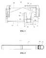
Fig. 1 is a top plan view of the joint equipment for boarding bridge of one embodiment according to the invention in an idle state.Fig. 2 is a sectional view along the line A-A inFig. 1 .Fig. 3 is a sectional view along the line D-D inFig. 1 .Fig. 4 is a sectional view along the line B-B inFig. 1 .Fig. 5 is a sectional view along the line C-C inFig. 1 .Fig. 6 is a sectional view along the line G-G inFig. 1 .Fig. 7 is a top plan view of the joint equipment of one embodiment according to the invention, which is in an operational state..Fig. 8 is a sectional view along the line E-E inFig. 7 .Fig. 9 is a sectional view along the line F-F inFig. 7 .Fig. 10 is a sectional view along the line H-H inFig. 7 .Fig. 11 is a side view showing the joint equipment of the boarding bridge according to one embodiment of the invention with its joining plate butting with the top tread of the extension line aircraft.Fig. 12 is a side view showing the joint equipment of the boarding bridge according to one embodiment of the invention with its joining plate lapping over the top tread of the extension line aircraft.- The invention will now be described in details through the following example embodiments. However, it is understood that an element, a structure or a feature in an embodiment can be beneficially incorporated into other embodiments without further recitation.
Figs. 1 to 6 show an embodiment of thejoint equipment 10 according to the invention, which is movably arranged at the front end of the boarding bridge and suitable for joining with an up and down opened boarding gate of an extension line aircraft. Thejoint equipment 10 comprises amovable floor frame 11 with twoferry plates 110 arranged at respective the left and the right sides of the rear end of thefloor frame 11. Preferably, each of the ferry plates is configured into a triangle-shaped structure for connecting with the tunnel of the boarding bridge, for example a rotunda arranged the end of the tunnel. Thefloor frame 11 is designed to have aconcave notch 12 at its front end. Afirst floor 13 is arranged at the opening of thenotch 12. Twofirst beams 131, preferably made of rectangular tubes, are arranged under and fixed to the left and the right ends of thefirst floor 13 respectively (seeingFig. 3 ). Asliding plate 14 is arranged under thefirst floor 13 and between thefirst beams 131. A joiningplate 15 is hinged to a front end of thesliding plate 14 through ahinge 141 so that the joiningplate 15 can be turned around thehinge 141 by a certain angle with respect to thesliding plate 14. A slide device is arranged under thesliding plate 14, through which thesliding plate 14 can slide with respect to thefirst floor 13.- A pair of
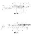
front cover plates 151 are respectively hinged to the left and the right ends of the joiningplate 15 throughhinges 150, while a pair ofrear cover plates 132 are respectively hinged to the left and the right ends of the joiningplate 13 throughhinges 135. The front and therear cover plates front cover plates 151 are partly lapped over and contact with the correspondingrear cover plates 132. Preferably, the joiningplate 15 is provided with afirst safety edge 152 at its front edge. As shown inFig. 2 , thefloor frame 11 is provided with a detachable and movablefront edge 111 at its front end, providing a protection to the aircraft. According to one embodiment of the invention, thefront edge 111 is detachably connected with thefloor frame 11, for example, throughbolts 112, so that it can be easily disassembled from thefloor frame 11 for replacing , repairing or maintenance. - As shown in
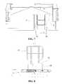
Figs. 3 and 4 , the slide device in one embodiment comprises twoguides 161 fixed to the inner sides of the respectivefirst beams 131 of thefloor frame 11 respectively and two sets ofrollers 162 arranged at the underside of the left and the right ends of thesliding plate 14 respectively. The sets ofrollers 162 are suitable to engage with and roll along therespective guides 161, so that thesliding plate 14 is slidable with respect to thefloor frame 11 along theguides 161. According to a preferred embodiment of the invention, theguides 161 are C-shaped guides. - In one embodiment of the invention, as shown in
Figs. 3 and6 , thejoint equipment 10 further comprises a pair ofturning mechanisms 17 arranged under the left and the right ends of thesliding plate 14 for turning the pair offront cover plates 151 and the pair ofrear cover plates 132. In particular, each of theturning mechanisms 17 comprises amounting seat 171, acurved lever 172, awedged block 173, awedged plate 175 cooperating with thewedged block 173, and a connectingplate 174. Themounting seat 171 is fixed at the bottom of thefirst beam 131 and/or theguide 161 under thefirst floor 13, and is preferably configured into a triangle structure with its one side being fixed (e.g. by welding) to the bottom of thefirst beam 131 and/or theguide 161 and its opposite downward angle being used as a hinge point A for connecting with thecurved lever 172. Preferably, thecurved lever 172 is hinged to themounting seat 171 at itsfirst end 172a, e.g. through a pin. Thewedged block 173 is fixed to thefirst end 172a of thecurved lever 172, while thewedged plate 175 is arranged at the underside of thesliding plate 14. The connectingplate 174 is fixed at the underside of the correspondingrear cover plate 132. Anelongated groove 174a is opened in each of the connectingplates 174, which thesecond end 172b of thecurved lever 172 is limited in and slides along. - Two
second beams 121, preferably made of rectangular tubes, are arranged at the undersides of thefloor frame 11 beside the periphery of thenotch 12 and paralleled to thefirst beams 131. Preferably, the first and/or thesecond beams second safety edges 153 at their bottoms. Advantageously, pressure sensors can be provided at the second safety edges 153 as well as the at thefirst safety edge 152 so as to reduce the collisions between the guardrail 21 (Figs. 11, 12 ) of the boarding gate and thejoint equipment 10, providing thus an effective protection to both the aircraft and the joint equipment. - Referring now to
Fig. 5 , for achieving the forward extension and backward retraction movement of the slidingplate 14, thejoint equipment 10 is provided with a activating device. In particularly, the activating device includes anactivator 181, which is connected to the underside of thefloor frame 11 at its one end and connected to the underside of the slidingplate 14 at its opposite end. Furthermore, aposition limiting block 143 is arranged under thehinge 141 for the joiningplate 15, so as to limit the extension of theactivator 181. Activated by theactivator 181, the slidingplate 14 can slide with respect to thefirst floor 13 through the movement of the sets ofrollers 162 alongguide 161 so as to realize the extension and/or retraction with respect to thefloor frame 11. In order to prevent the slidingplate 14 from the collision with thefloor frame 11 when it retracts, acollision preventing block 163 is arranged at the rear end of at least one of theguides 161. - Referring now to
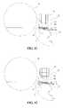
Figs. 7 to 10 , when the slidingplate 14 retracts as theactivator 181 retracts, the wedgedplate 175 at the underside of the slidingplate 14 engages with the wedgedblocks 173 fixed at the first ends 172a of thecurved levers 172 and forces them to rotate downwardly, so that thecurved levers 172 rotates around the respective hinge points A. Meanwhile, thesecond end 172b of each of thecurved levers 172 slide from the outer end of theelongated groove 174a to the opposite inner end of thegroove 174a, forcing therear cover plate 132 and thefront cover plate 151 lapping over said rear one turn upwardly around theirhinges first floor 13 and thefloor frame 11. Holes can be formed at the areas offloor frame 11 adjacent to the sides of theconcave notch 12, into which plug-and-play typedguardrails 19 can be inserted to increase the safety for the passengers who enter thejoint equipment 10. - Referring now to
Figs. 11 and 12 , thejoint equipment 10 is in the operational state and joining with anextension line aircraft 20. At this time, theactivator 181 retracts backwardly and forces the slidingplate 14 retracts accordingly, so that a void space presents in front of thefirst floor 13 for accommodating the treads of the downward turned boarding gate of theextension line aircraft 20. Thefront cover plates 151 and therear cover plates 132 are turned upwardly, presenting the gaps between thefloor frame 11 and thefirst floor 13 for accommodating theguardrail 21 of the boarding gate of theextension line aircraft 20. Theguardrails 19 can be then inserted into the holes on thefloor frame 11 adjacent to thenotch 12 to increase safety. In the example shown inFig. 11 , the front edge of the joiningplate 15 butts and flushes with thetop tread 22 of theextension line aircraft 20.Fig. 12 shows thejoint equipment 10 is in another operational state, in which the joiningplate 15 lapping over thetop tread 22 of theextension line aircraft 20. When thetop tread 22 of theaircraft 20 is raised as theaircraft 20 becoming empty, thelapping joining plate 15 with thetop tread 22 ensures the stability of the joining between the boarding bridge and theaircraft 20. - Although several preferred embodiments of the present invention have been described, the present invention may be used with other configurations. It will be appreciated by those skilled in the art that, the present invention could have many other embodiments, and changes and modifications may be made thereto without departing from the invention in its broader aspects and as set forth in the following claims and equivalents thereof.
Claims (11)
- A joint equipment for (10) a boarding bridge, for joining with a boarding gate of an aircraft, said joint equipment comprising:a floor frame (11) having a concave notch (12) at its front end;a first floor (13) arranged at the opening of the concave notch;a sliding plate (14) arranged under the first floor (13) and slidable with respect to the first floor through a slide device (161, 162) arranged under the sliding plate;a joining plate (15) rotatably connected in the front end of the sliding plate;a pair of front cover plates (151) rotatably connected to the left and the right ends of the joining plate (15) respectively;a pair of rear cover plates (132) rotatably connected to the left and the right ends of the first floor (13) respectively, wherein the pair of front cover plates (151) are partly lapped over the pair of rear cover plates (132) respectively;an activating device (181) for operating sliding movement of the sliding plate with respect to the first floor; anda pair of turning mechanisms (17) arranged under the left and the right sides of the sliding plate (14) respectively, for turning the pairs of the front and the rear cover plates (151, 132) with respect to the joining plate (15) and the first floor.
- The joint equipment of the boarding bridge according to Claim 1, wherein the slide device comprises:two first beams arranged under and fixed to respective the left and the right ends of the first floor;two guides fixed to the inner sides of the respective first beams; andtwo sets of rollers arranged at the underside of the sliding plate and suitable for engaging with and rolling along the guide.
- The joint equipment of the boarding bridge according to Claim 2, wherein each of the guides is equipped with a collision preventing block at its at least one end.
- The joint equipment of the boarding bridge according to Claim 1, wherein the activating device comprises an activator with its one end connected to the underside of the floor frame and its opposite end connected to the underside of the sliding plate.
- The joint equipment of the boarding bridge according to Claim 1, further comprising a guardrail, which can be detachably installed onto the floor frame by inserting into holes arranged in the floor frame adjacent to the notch.
- The joint equipment of the boarding bridge according to Claim 1, wherein each of the turning mechanism comprises:a mounting seat having a substantively triangle profile with its one side part being fixed to the bottoms of the corresponding ones of the first beams and the guides and its downward angle part being used as a hinge point;a curved lever having a first end pivotably connected to the hinge point and a second end,a wedged block fixed to the first end of the curved lever;a wedged plate arranged at the underside of the sliding plate for engaging and cooperating with the wedged block; anda connecting plate fixed to the underside of the corresponding rear cover plate and having an elongated groove therein, wherein the second end of the curved lever is configured to be suitable to limited in and slides along the elongated groove.
- The joint equipment of the boarding bridge according to Claim 1, wherein the floor frame is arranged with two ferry plates at left and right sides of its rear end respectively.
- The joint equipment of the boarding bridge according to Claim 1, wherein a safety edge is arranged at the front end of the joining plate, with a pressure sensor arranged thereon.
- The joint equipment of the boarding bridge according to Claim 2 , wherein two second beams are arranged at the underside of the floor frame beside the notch, parallel to the first beams,
wherein safety edges are arranged face to face at the bottoms of the corresponding first and second beams, with a pressure sensor arranged thereon. - The joint equipment of the boarding bridge according to Claim 1, wherein a detachable and movable front edge is arranged at the front end of the floor frame.
- A boarding bridge for connecting a terminal building with an aircraft, comprising:a tunnel having a front end and a rear end connected with the terminal building;a rotunda arranged at the front end of the tunnel; anda joint equipment as that of any claims 1-10, wherein the floor frame of the joint equipment is movably connected to the rotunda.
Applications Claiming Priority (2)
| Application Number | Priority Date | Filing Date | Title |
|---|---|---|---|
| CN201010160675.4ACN102233954B (en) | 2010-04-26 | 2010-04-26 | Boarding bridge joint device |
| PCT/CN2011/000737WO2011134278A1 (en) | 2010-04-26 | 2011-04-26 | Joint equipment and boarding bridge having the same |
Publications (3)
| Publication Number | Publication Date |
|---|---|
| EP2563669A1 EP2563669A1 (en) | 2013-03-06 |
| EP2563669A4 EP2563669A4 (en) | 2014-06-25 |
| EP2563669B1true EP2563669B1 (en) | 2015-07-01 |
Family
ID=44814502
Family Applications (1)
| Application Number | Title | Priority Date | Filing Date |
|---|---|---|---|
| EP11774269.2ANot-in-forceEP2563669B1 (en) | 2010-04-26 | 2011-04-26 | Joint equipment and boarding bridge having the same |
Country Status (5)
| Country | Link |
|---|---|
| US (1) | US8555444B2 (en) |
| EP (1) | EP2563669B1 (en) |
| CN (1) | CN102233954B (en) |
| ES (1) | ES2548876T3 (en) |
| WO (1) | WO2011134278A1 (en) |
Families Citing this family (12)
| Publication number | Priority date | Publication date | Assignee | Title |
|---|---|---|---|---|
| US20080093784A1 (en)* | 2006-08-29 | 2008-04-24 | Rawls-Meehan Martin B | Foam spring mattress configured with variable firmness |
| JP5759299B2 (en)* | 2011-08-02 | 2015-08-05 | 新明和工業株式会社 | Boarding bridge |
| CN103662074B (en)* | 2012-09-17 | 2016-03-30 | 深圳中集天达空港设备有限公司 | A kind of boarding bridge joint device and there is its connecting bridge and the method that picks thereof |
| CN102991694A (en)* | 2012-10-16 | 2013-03-27 | 蒂森克虏伯机场系统(中山)有限公司 | Multi-purpose boarding bridge floor |
| CN102991707B (en)* | 2012-11-23 | 2015-06-10 | 溧阳市科技开发中心 | Shed device for boarding bridge |
| CN102975863B (en)* | 2012-11-23 | 2015-06-10 | 溧阳市科技开发中心 | Folding tent for boarding bridge |
| KR101445244B1 (en)* | 2013-07-03 | 2014-09-29 | 한국공항공사 | Auto slope control system |
| JP6419485B2 (en)* | 2014-08-18 | 2018-11-07 | 三菱重工交通機器エンジニアリング株式会社 | Swivel floor, passenger boarding bridge, swivel floor aircraft connection method, and passenger boarding bridge remodeling method |
| CN106864767B (en)* | 2015-12-10 | 2019-08-06 | 中国国际海运集装箱(集团)股份有限公司 | Arrival gates and boarding bridges with such gates |
| CN106428610A (en)* | 2016-09-30 | 2017-02-22 | 美迪斯智能装备有限公司 | A safety control device for boarding bridge |
| CN112046781B (en)* | 2020-09-11 | 2022-03-01 | 深圳中集天达空港设备有限公司 | Boarding bridge collision avoidance method and boarding bridge collision avoidance system |
| CN112265646B (en)* | 2020-10-30 | 2022-04-29 | 深圳中集天达空港设备有限公司 | Control method of boarding bridge and related equipment |
Family Cites Families (22)
| Publication number | Priority date | Publication date | Assignee | Title |
|---|---|---|---|---|
| US3126112A (en)* | 1964-03-24 | Airplane cargo and service vehicle | ||
| US3664456A (en)* | 1970-07-20 | 1972-05-23 | Wollard Aircraft Equipment Inc | Conveyance servicing structure |
| US5761757A (en)* | 1996-11-01 | 1998-06-09 | Fmc Corporation | Passenger boarding bridge for servicing commuter aircraft |
| US6131225A (en)* | 1997-04-15 | 2000-10-17 | Otis Elevator Company | Docking assembly for a shuttle |
| US6122789A (en)* | 1998-04-01 | 2000-09-26 | Johnnie C. Telford | Aircraft passenger boarding bridge system |
| CN2338271Y (en)* | 1998-06-30 | 1999-09-15 | 深圳中集天达空港设备有限公司 | Light wt. bridge extending between terminal building and aircraft |
| DE19911879C1 (en)* | 1999-03-17 | 2000-08-10 | Thyssen Henschel Airport Syste | Aircraft bridge cabin for entry and exit of passengers has front roof and floor extending over complete width of roof, undivided floor having railing in area of lateral edge |
| US6195826B1 (en)* | 1999-05-28 | 2001-03-06 | Fmc Corporation | Aircraft engagement assembly for aircraft boarding bridges |
| US20020017002A1 (en)* | 2000-05-19 | 2002-02-14 | Sloan Gary E. | Passenger bridge for aircraft |
| US6898816B2 (en)* | 2000-10-05 | 2005-05-31 | Fmc Technologies, Inc. | Adaptable cab floor engagement assembly for commuter and conventional jet aircraft |
| WO2002028713A2 (en)* | 2000-10-05 | 2002-04-11 | Fmc Corporation | Adaptable cab floor engagement assembly for commuter and conventional jet aircraft |
| US6691361B2 (en)* | 2001-03-30 | 2004-02-17 | Dew Engineering And Development Limited | Extensible platform on an extensible passenger loading bridge |
| US6802096B2 (en)* | 2002-06-14 | 2004-10-12 | Dew Engineering And Development Limited | Retractable floor assembly for a passenger loading bridge |
| US6757926B2 (en)* | 2002-09-12 | 2004-07-06 | The Boeing Company | Retractable bridge extension system |
| SE526736C2 (en)* | 2004-03-23 | 2005-11-01 | Fmt Int Trade Ab | Aircraft passenger jetty device |
| CN2839113Y (en)* | 2005-08-22 | 2006-11-22 | 中国国际海运集装箱(集团)股份有限公司 | Connecting device between terminal building and aircraft |
| CN100554087C (en)* | 2006-08-02 | 2009-10-28 | 中国国际海运集装箱(集团)股份有限公司 | Boarding bridge and integral lifting platform device thereof |
| CN100471760C (en)* | 2007-03-22 | 2009-03-25 | 中国国际海运集装箱(集团)股份有限公司 | Opening and closing device for boarding bridge canopy |
| CN201095423Y (en)* | 2007-08-16 | 2008-08-06 | 中国国际海运集装箱(集团)股份有限公司 | Floor structure for aerobridge boarding gate |
| JP5111075B2 (en)* | 2007-11-30 | 2012-12-26 | 全日空モーターサービス株式会社 | Boarding bridge, boarding bridge system, and mounting method of boarding bridge |
| JP4663748B2 (en)* | 2008-03-10 | 2011-04-06 | 三菱重工交通機器エンジニアリング株式会社 | Boarding bridge connections and boarding bridges |
| CN101659325B (en)* | 2008-08-27 | 2013-03-27 | 深圳中集天达空港设备有限公司 | Boarding bridge flexible connection device |
- 2010
- 2010-04-26CNCN201010160675.4Apatent/CN102233954B/enactiveActive
- 2011
- 2011-04-25USUS13/093,340patent/US8555444B2/enactiveActive
- 2011-04-26EPEP11774269.2Apatent/EP2563669B1/ennot_activeNot-in-force
- 2011-04-26WOPCT/CN2011/000737patent/WO2011134278A1/enactiveApplication Filing
- 2011-04-26ESES11774269.2Tpatent/ES2548876T3/enactiveActive
Also Published As
| Publication number | Publication date |
|---|---|
| US20110258787A1 (en) | 2011-10-27 |
| EP2563669A1 (en) | 2013-03-06 |
| US8555444B2 (en) | 2013-10-15 |
| CN102233954B (en) | 2013-07-03 |
| ES2548876T3 (en) | 2015-10-21 |
| EP2563669A4 (en) | 2014-06-25 |
| CN102233954A (en) | 2011-11-09 |
| WO2011134278A1 (en) | 2011-11-03 |
Similar Documents
| Publication | Publication Date | Title |
|---|---|---|
| EP2563669B1 (en) | Joint equipment and boarding bridge having the same | |
| US10377505B2 (en) | Passageway to board and deplane an airplane | |
| EP2003086B1 (en) | Vehicle for passenger entry and exit | |
| CA2851841C (en) | Adaptable platform for loading and unloading railway cars | |
| JP6250796B2 (en) | A device that interfaces a boarding bridge with a low-sill airplane | |
| US9434482B2 (en) | Cab of passenger boarding bridge and passenger boarding bridge having the same and docking method thereof | |
| US20090106918A1 (en) | Retractable Ramp | |
| US20110271597A1 (en) | Gate for barrier system and methods for the assembly and use thereof | |
| CN106006330A (en) | Passenger conveyor | |
| US6802096B2 (en) | Retractable floor assembly for a passenger loading bridge | |
| US6691361B2 (en) | Extensible platform on an extensible passenger loading bridge | |
| US10232956B2 (en) | Aerobridge providing multiple access points to aircraft vehicle | |
| US7596826B2 (en) | Device for passenger bridges for aircraft | |
| CN205113483U (en) | A telescopic removal counter weight device for bridge inspect vehicle | |
| KR101389948B1 (en) | Boarding bridge | |
| KR20080046117A (en) | Mobile ramp connecting the aircraft to the boarding bridge | |
| KR20130051575A (en) | A boarding bridge has a wheel chair moving apparatus | |
| US20030145399A1 (en) | Extendable passenger loading bridge having improved placement of roller assemblies | |
| JP5010984B2 (en) | Passenger conveyor | |
| GB2453237A (en) | An access system |
Legal Events
| Date | Code | Title | Description |
|---|---|---|---|
| PUAI | Public reference made under article 153(3) epc to a published international application that has entered the european phase | Free format text:ORIGINAL CODE: 0009012 | |
| 17P | Request for examination filed | Effective date:20121019 | |
| AK | Designated contracting states | Kind code of ref document:A1 Designated state(s):AL AT BE BG CH CY CZ DE DK EE ES FI FR GB GR HR HU IE IS IT LI LT LU LV MC MK MT NL NO PL PT RO RS SE SI SK SM TR | |
| DAX | Request for extension of the european patent (deleted) | ||
| A4 | Supplementary search report drawn up and despatched | Effective date:20140522 | |
| RIC1 | Information provided on ipc code assigned before grant | Ipc:B64F 1/305 20060101AFI20140516BHEP | |
| GRAP | Despatch of communication of intention to grant a patent | Free format text:ORIGINAL CODE: EPIDOSNIGR1 | |
| INTG | Intention to grant announced | Effective date:20150129 | |
| GRAS | Grant fee paid | Free format text:ORIGINAL CODE: EPIDOSNIGR3 | |
| GRAA | (expected) grant | Free format text:ORIGINAL CODE: 0009210 | |
| AK | Designated contracting states | Kind code of ref document:B1 Designated state(s):AL AT BE BG CH CY CZ DE DK EE ES FI FR GB GR HR HU IE IS IT LI LT LU LV MC MK MT NL NO PL PT RO RS SE SI SK SM TR | |
| REG | Reference to a national code | Ref country code:GB Ref legal event code:FG4D | |
| REG | Reference to a national code | Ref country code:AT Ref legal event code:REF Ref document number:733794 Country of ref document:AT Kind code of ref document:T Effective date:20150715 Ref country code:CH Ref legal event code:EP | |
| REG | Reference to a national code | Ref country code:IE Ref legal event code:FG4D | |
| REG | Reference to a national code | Ref country code:DE Ref legal event code:R096 Ref document number:602011017530 Country of ref document:DE | |
| REG | Reference to a national code | Ref country code:SE Ref legal event code:TRGR | |
| REG | Reference to a national code | Ref country code:ES Ref legal event code:FG2A Ref document number:2548876 Country of ref document:ES Kind code of ref document:T3 Effective date:20151021 | |
| REG | Reference to a national code | Ref country code:AT Ref legal event code:MK05 Ref document number:733794 Country of ref document:AT Kind code of ref document:T Effective date:20150701 | |
| REG | Reference to a national code | Ref country code:NL Ref legal event code:FP | |
| REG | Reference to a national code | Ref country code:NO Ref legal event code:T2 Effective date:20150701 | |
| REG | Reference to a national code | Ref country code:LT Ref legal event code:MG4D | |
| PG25 | Lapsed in a contracting state [announced via postgrant information from national office to epo] | Ref country code:GR Free format text:LAPSE BECAUSE OF FAILURE TO SUBMIT A TRANSLATION OF THE DESCRIPTION OR TO PAY THE FEE WITHIN THE PRESCRIBED TIME-LIMIT Effective date:20151002 Ref country code:LV Free format text:LAPSE BECAUSE OF FAILURE TO SUBMIT A TRANSLATION OF THE DESCRIPTION OR TO PAY THE FEE WITHIN THE PRESCRIBED TIME-LIMIT Effective date:20150701 Ref country code:LT Free format text:LAPSE BECAUSE OF FAILURE TO SUBMIT A TRANSLATION OF THE DESCRIPTION OR TO PAY THE FEE WITHIN THE PRESCRIBED TIME-LIMIT Effective date:20150701 | |
| PG25 | Lapsed in a contracting state [announced via postgrant information from national office to epo] | Ref country code:PL Free format text:LAPSE BECAUSE OF FAILURE TO SUBMIT A TRANSLATION OF THE DESCRIPTION OR TO PAY THE FEE WITHIN THE PRESCRIBED TIME-LIMIT Effective date:20150701 Ref country code:RS Free format text:LAPSE BECAUSE OF FAILURE TO SUBMIT A TRANSLATION OF THE DESCRIPTION OR TO PAY THE FEE WITHIN THE PRESCRIBED TIME-LIMIT Effective date:20150701 Ref country code:AT Free format text:LAPSE BECAUSE OF FAILURE TO SUBMIT A TRANSLATION OF THE DESCRIPTION OR TO PAY THE FEE WITHIN THE PRESCRIBED TIME-LIMIT Effective date:20150701 Ref country code:IS Free format text:LAPSE BECAUSE OF FAILURE TO SUBMIT A TRANSLATION OF THE DESCRIPTION OR TO PAY THE FEE WITHIN THE PRESCRIBED TIME-LIMIT Effective date:20151101 Ref country code:PT Free format text:LAPSE BECAUSE OF FAILURE TO SUBMIT A TRANSLATION OF THE DESCRIPTION OR TO PAY THE FEE WITHIN THE PRESCRIBED TIME-LIMIT Effective date:20151102 Ref country code:HR Free format text:LAPSE BECAUSE OF FAILURE TO SUBMIT A TRANSLATION OF THE DESCRIPTION OR TO PAY THE FEE WITHIN THE PRESCRIBED TIME-LIMIT Effective date:20150701 | |
| REG | Reference to a national code | Ref country code:DE Ref legal event code:R097 Ref document number:602011017530 Country of ref document:DE | |
| PG25 | Lapsed in a contracting state [announced via postgrant information from national office to epo] | Ref country code:DK Free format text:LAPSE BECAUSE OF FAILURE TO SUBMIT A TRANSLATION OF THE DESCRIPTION OR TO PAY THE FEE WITHIN THE PRESCRIBED TIME-LIMIT Effective date:20150701 Ref country code:EE Free format text:LAPSE BECAUSE OF FAILURE TO SUBMIT A TRANSLATION OF THE DESCRIPTION OR TO PAY THE FEE WITHIN THE PRESCRIBED TIME-LIMIT Effective date:20150701 Ref country code:CZ Free format text:LAPSE BECAUSE OF FAILURE TO SUBMIT A TRANSLATION OF THE DESCRIPTION OR TO PAY THE FEE WITHIN THE PRESCRIBED TIME-LIMIT Effective date:20150701 Ref country code:SK Free format text:LAPSE BECAUSE OF FAILURE TO SUBMIT A TRANSLATION OF THE DESCRIPTION OR TO PAY THE FEE WITHIN THE PRESCRIBED TIME-LIMIT Effective date:20150701 | |
| PGFP | Annual fee paid to national office [announced via postgrant information from national office to epo] | Ref country code:ES Payment date:20160217 Year of fee payment:6 Ref country code:NO Payment date:20160126 Year of fee payment:6 | |
| PLBE | No opposition filed within time limit | Free format text:ORIGINAL CODE: 0009261 | |
| STAA | Information on the status of an ep patent application or granted ep patent | Free format text:STATUS: NO OPPOSITION FILED WITHIN TIME LIMIT | |
| PG25 | Lapsed in a contracting state [announced via postgrant information from national office to epo] | Ref country code:RO Free format text:LAPSE BECAUSE OF FAILURE TO SUBMIT A TRANSLATION OF THE DESCRIPTION OR TO PAY THE FEE WITHIN THE PRESCRIBED TIME-LIMIT Effective date:20150701 | |
| PGFP | Annual fee paid to national office [announced via postgrant information from national office to epo] | Ref country code:NL Payment date:20160210 Year of fee payment:6 Ref country code:FI Payment date:20160308 Year of fee payment:6 | |
| 26N | No opposition filed | Effective date:20160404 | |
| PG25 | Lapsed in a contracting state [announced via postgrant information from national office to epo] | Ref country code:SI Free format text:LAPSE BECAUSE OF FAILURE TO SUBMIT A TRANSLATION OF THE DESCRIPTION OR TO PAY THE FEE WITHIN THE PRESCRIBED TIME-LIMIT Effective date:20150701 Ref country code:BE Free format text:LAPSE BECAUSE OF NON-PAYMENT OF DUE FEES Effective date:20160430 | |
| REG | Reference to a national code | Ref country code:DE Ref legal event code:R119 Ref document number:602011017530 Country of ref document:DE | |
| REG | Reference to a national code | Ref country code:SE Ref legal event code:EUG | |
| REG | Reference to a national code | Ref country code:CH Ref legal event code:PL | |
| GBPC | Gb: european patent ceased through non-payment of renewal fee | Effective date:20160426 | |
| PG25 | Lapsed in a contracting state [announced via postgrant information from national office to epo] | Ref country code:LU Free format text:LAPSE BECAUSE OF FAILURE TO SUBMIT A TRANSLATION OF THE DESCRIPTION OR TO PAY THE FEE WITHIN THE PRESCRIBED TIME-LIMIT Effective date:20160426 | |
| REG | Reference to a national code | Ref country code:IE Ref legal event code:MM4A | |
| REG | Reference to a national code | Ref country code:FR Ref legal event code:ST Effective date:20161230 | |
| PG25 | Lapsed in a contracting state [announced via postgrant information from national office to epo] | Ref country code:DE Free format text:LAPSE BECAUSE OF NON-PAYMENT OF DUE FEES Effective date:20161101 Ref country code:CH Free format text:LAPSE BECAUSE OF NON-PAYMENT OF DUE FEES Effective date:20160430 Ref country code:GB Free format text:LAPSE BECAUSE OF NON-PAYMENT OF DUE FEES Effective date:20160426 Ref country code:LI Free format text:LAPSE BECAUSE OF NON-PAYMENT OF DUE FEES Effective date:20160430 Ref country code:FR Free format text:LAPSE BECAUSE OF NON-PAYMENT OF DUE FEES Effective date:20160502 | |
| PG25 | Lapsed in a contracting state [announced via postgrant information from national office to epo] | Ref country code:SE Free format text:LAPSE BECAUSE OF NON-PAYMENT OF DUE FEES Effective date:20160427 | |
| PG25 | Lapsed in a contracting state [announced via postgrant information from national office to epo] | Ref country code:IE Free format text:LAPSE BECAUSE OF NON-PAYMENT OF DUE FEES Effective date:20160426 | |
| PG25 | Lapsed in a contracting state [announced via postgrant information from national office to epo] | Ref country code:IT Free format text:LAPSE BECAUSE OF NON-PAYMENT OF DUE FEES Effective date:20160426 | |
| REG | Reference to a national code | Ref country code:NO Ref legal event code:MMEP | |
| REG | Reference to a national code | Ref country code:NL Ref legal event code:MM Effective date:20170501 | |
| PG25 | Lapsed in a contracting state [announced via postgrant information from national office to epo] | Ref country code:FI Free format text:LAPSE BECAUSE OF NON-PAYMENT OF DUE FEES Effective date:20170426 Ref country code:NO Free format text:LAPSE BECAUSE OF NON-PAYMENT OF DUE FEES Effective date:20170430 Ref country code:NL Free format text:LAPSE BECAUSE OF NON-PAYMENT OF DUE FEES Effective date:20170501 | |
| PG25 | Lapsed in a contracting state [announced via postgrant information from national office to epo] | Ref country code:CY Free format text:LAPSE BECAUSE OF FAILURE TO SUBMIT A TRANSLATION OF THE DESCRIPTION OR TO PAY THE FEE WITHIN THE PRESCRIBED TIME-LIMIT Effective date:20150701 Ref country code:HU Free format text:LAPSE BECAUSE OF FAILURE TO SUBMIT A TRANSLATION OF THE DESCRIPTION OR TO PAY THE FEE WITHIN THE PRESCRIBED TIME-LIMIT; INVALID AB INITIO Effective date:20110426 Ref country code:SM Free format text:LAPSE BECAUSE OF FAILURE TO SUBMIT A TRANSLATION OF THE DESCRIPTION OR TO PAY THE FEE WITHIN THE PRESCRIBED TIME-LIMIT Effective date:20150701 | |
| PG25 | Lapsed in a contracting state [announced via postgrant information from national office to epo] | Ref country code:MC Free format text:LAPSE BECAUSE OF FAILURE TO SUBMIT A TRANSLATION OF THE DESCRIPTION OR TO PAY THE FEE WITHIN THE PRESCRIBED TIME-LIMIT Effective date:20150701 Ref country code:MT Free format text:LAPSE BECAUSE OF NON-PAYMENT OF DUE FEES Effective date:20160430 Ref country code:MK Free format text:LAPSE BECAUSE OF FAILURE TO SUBMIT A TRANSLATION OF THE DESCRIPTION OR TO PAY THE FEE WITHIN THE PRESCRIBED TIME-LIMIT Effective date:20150701 Ref country code:TR Free format text:LAPSE BECAUSE OF FAILURE TO SUBMIT A TRANSLATION OF THE DESCRIPTION OR TO PAY THE FEE WITHIN THE PRESCRIBED TIME-LIMIT Effective date:20150701 | |
| REG | Reference to a national code | Ref country code:ES Ref legal event code:FD2A Effective date:20180629 | |
| PG25 | Lapsed in a contracting state [announced via postgrant information from national office to epo] | Ref country code:BG Free format text:LAPSE BECAUSE OF FAILURE TO SUBMIT A TRANSLATION OF THE DESCRIPTION OR TO PAY THE FEE WITHIN THE PRESCRIBED TIME-LIMIT Effective date:20150701 Ref country code:ES Free format text:LAPSE BECAUSE OF NON-PAYMENT OF DUE FEES Effective date:20170427 | |
| PG25 | Lapsed in a contracting state [announced via postgrant information from national office to epo] | Ref country code:AL Free format text:LAPSE BECAUSE OF FAILURE TO SUBMIT A TRANSLATION OF THE DESCRIPTION OR TO PAY THE FEE WITHIN THE PRESCRIBED TIME-LIMIT Effective date:20150701 |