EP2562970B1 - Switch, and flow table control method - Google Patents
Switch, and flow table control methodDownload PDFInfo
- Publication number
- EP2562970B1 EP2562970B1EP11771903.9AEP11771903AEP2562970B1EP 2562970 B1EP2562970 B1EP 2562970B1EP 11771903 AEP11771903 AEP 11771903AEP 2562970 B1EP2562970 B1EP 2562970B1
- Authority
- EP
- European Patent Office
- Prior art keywords
- flow
- flow table
- save
- normal
- registered
- Prior art date
- Legal status (The legal status is an assumption and is not a legal conclusion. Google has not performed a legal analysis and makes no representation as to the accuracy of the status listed.)
- Not-in-force
Links
Images


Classifications
- H—ELECTRICITY
- H04—ELECTRIC COMMUNICATION TECHNIQUE
- H04L—TRANSMISSION OF DIGITAL INFORMATION, e.g. TELEGRAPHIC COMMUNICATION
- H04L49/00—Packet switching elements
- H04L49/25—Routing or path finding in a switch fabric
- H04L49/252—Store and forward routing
- H—ELECTRICITY
- H04—ELECTRIC COMMUNICATION TECHNIQUE
- H04L—TRANSMISSION OF DIGITAL INFORMATION, e.g. TELEGRAPHIC COMMUNICATION
- H04L45/00—Routing or path finding of packets in data switching networks
- H04L45/38—Flow based routing
- H—ELECTRICITY
- H04—ELECTRIC COMMUNICATION TECHNIQUE
- H04L—TRANSMISSION OF DIGITAL INFORMATION, e.g. TELEGRAPHIC COMMUNICATION
- H04L45/00—Routing or path finding of packets in data switching networks
- H04L45/02—Topology update or discovery
- H04L45/021—Ensuring consistency of routing table updates, e.g. by using epoch numbers
- H—ELECTRICITY
- H04—ELECTRIC COMMUNICATION TECHNIQUE
- H04L—TRANSMISSION OF DIGITAL INFORMATION, e.g. TELEGRAPHIC COMMUNICATION
- H04L45/00—Routing or path finding of packets in data switching networks
- H04L45/02—Topology update or discovery
- H—ELECTRICITY
- H04—ELECTRIC COMMUNICATION TECHNIQUE
- H04L—TRANSMISSION OF DIGITAL INFORMATION, e.g. TELEGRAPHIC COMMUNICATION
- H04L47/00—Traffic control in data switching networks
- H04L47/10—Flow control; Congestion control
- H04L47/24—Traffic characterised by specific attributes, e.g. priority or QoS
- H04L47/2441—Traffic characterised by specific attributes, e.g. priority or QoS relying on flow classification, e.g. using integrated services [IntServ]
- H—ELECTRICITY
- H04—ELECTRIC COMMUNICATION TECHNIQUE
- H04L—TRANSMISSION OF DIGITAL INFORMATION, e.g. TELEGRAPHIC COMMUNICATION
- H04L49/00—Packet switching elements
- H04L49/25—Routing or path finding in a switch fabric
- H04L49/253—Routing or path finding in a switch fabric using establishment or release of connections between ports
- H04L49/254—Centralised controller, i.e. arbitration or scheduling
- H—ELECTRICITY
- H04—ELECTRIC COMMUNICATION TECHNIQUE
- H04L—TRANSMISSION OF DIGITAL INFORMATION, e.g. TELEGRAPHIC COMMUNICATION
- H04L49/00—Packet switching elements
- H04L49/55—Prevention, detection or correction of errors
- H04L49/557—Error correction, e.g. fault recovery or fault tolerance
Definitions
- the present inventionis related to a switch, and more particularly to a switch in an open flow system.
- a single switchperformed a routing control and a packet transfer.
- OpenflowOpenflow
- Wire Protocol 0x98Wired Protocol 0x98
- Current MaintainerBrandon Heller (brandonh@stanford.edu) [online] (http://www.openflowthe switch.org/documents/openflow-spec-v0.9.0.pdf)).
- the controllermonitors the switch in the network and dynamically sets a transmission route of packets to the switches in the network according to the communication situation.
- the controllerregisters a flow on the switch by using an open flow protocol (Openflow Protocol) message to generate a flow table.
- Openflow ProtocolOpenflow Protocol
- the flowdefines predetermined processing (action) to be done to the packets which conforms to a predetermined rule (rule).
- the rule of the flowis defined by various combinations of any or all of a destination address, a source address, a destination port, and a source port, which are contained in a header region of a frame which carries the packet, and the rule can be identified. It should be noted that it is supposed that it contains MAC address (Media Access Control Address) and IP address (Internet Protocol Address) in the above-mentioned addresses. Also, the data of input port (Ingress Port) in addition to the above, is practicable as the rule of the flow.
- MAC addressMedia Access Control Address
- IP addressInternet Protocol Address
- the flow tablestores data of the flow (flow entry) every switch.
- the switchIn the open flow system, the switch carries out the packet transfer according to the generated flow table. The switch needs to confirm whether the flow conforms to a platform function of the switch, before registering of the flow received from the controller on the flow in response to an open flow protocol message table. The switch determines that the conformed flow is a valid flow and an un-conformed flow is an invalid flow, and registers the valid flow on the flow table.
- the controller and switch of the open flow systemare sometimes called an open flow controller (Openflow controller) and an open flow switch (Openflow switch) respectively.
- Flow Modflow modification
- a response message indicating whether or not the generation of a flow entry is succeededis not defined. Therefore, in order to confirm by the controller whether or not a flow entry has been registered, it is necessary to compare the flow data required in the registration and the flow data acquired in a statistics request (Statistics Request) message.
- a response message to notify the result to the controlleris not defined in the flow modification (Flow Mod) message to carry out a flow setting from the controller to the switch. Therefore, in order to know the setting result by the controller, it is necessary to confirm by using a statistics request (Statistics Request) message.
- the flow table in the switchretains only the entries of valid flows and does not retain any entry of an invalid flow.
- JP 2004-056340Adiscloses an L3 switch having a flow table.
- JP 2006-254134Adiscloses that flow identification data is outputted when there is a flow entry conforming to a search condition, and addition/deletion of the flow entry to/from the flow table is carried out when there is not the flow entry conforming thereto.
- JP 2008-167340Adiscloses a technique that a packet relay unit is provided with a flow table in which the pattern of a packet as an object of the flow identification is described.
- JP 2009-049592Adiscloses a technique that a search key and each of flow entries registered on the flow table are compared each time an IP packet is received, and that the statistic data such as the number of times of matching and a total packet length for the matching flow entry are updated.
- WO 2009/042919 A2discloses methods of managing a network whereby a view of the current state of the network is maintained.
- JP 2004-173136Adiscloses a technique to reduce the load of a network management device.
- JP 2008-177806discloses a network and fault controller, the controller capable of transferring packets when multiple faults occur.
- JP 2009-296230discloses a channel switching method and apparatus for a transmission network.
- a switch of the present inventionin which a flow entry with a rule and processing (action) defined to uniformly control packets as a flow is registered on a flow table of the switch, is provided with a platform function managing section for confirming whether or not a flow notified from a controller conforms with a predetermined function and determining whether or not the flow is valid or invalid; a flow table control section for registering a valid flow on a normal flow table and for registering an invalid flow on a save flow table such that flows not conforming to the predetermined function are retained; and a message processing section for recognizing a packet received from a network as a flow and performing processing specified for the flow on the packet when the flow is registered in the normal flow table.
- a flow table controlling method of the present invention for use in a switchcomprises the steps of: confirming whether or not a flow notified from a controller conforms with a predetermined function to determine whether the flow is a valid flow or an invalid flow; registering the valid flow on a normal flow table; registering the invalid flow on a save flow table such that flows not conforming to the predetermined function are retained; and recognizing a packet received from a network as a flow and carrying out processing specified to the flow on the packet when the flow has been registered in the normal flow table.
- a flow table control program of the present inventionis a program for making a switch execute: confirming whether or not a flow notified from a controller conforms with a predetermined function to determine whether the flow is a valid flow or an invalid flow; registering the valid flow on a normal flow table; registering the invalid flow on a save flow table; and recognizing a packet received from a network as a flow and carrying out processing specified to the flow to the packet when the flow has been registered on the normal flow table.
- the flow table control program of present inventioncan be stored in a storage unit and a storage medium.
- the controllercan determine whether or not the flow could be registered on the flow table of the switch.
- the open flow system of the present inventionis provided with a controller 10 and a switch 20.
- the controller 10forms one open flow system together with the switch 20 and transmits and receives an open flow protocol message.
- the switch 20is provided with a message processing section 21, a flow table control section 22, a platform function managing section 23, configuration data 24, a flow table 25 and a flow table reading section 26.
- the message processing section 21receives an open flow protocol message from the controller 10, analyzes the message, handles it by an appropriate one of inner modules of switch 20, assembles an open flow protocol message in response to a request from the one inner module and transmits it to the controller 10.
- a flow modification (Flow Mod) message and a statistic request messageexist as the open flow protocol messages.
- the flow modification (Flow Mod) messageis a message for setting a flow entry to the flow table 25 of the switch 20 (addition, modification, deletion) or for generating the flow table 25.
- the statistic request messageis a message for requesting statistic data of the flow entries, ports and the flow table 25 of the switch 20.
- the flow table control section 22inquires a confirmation of a flow received from the message processing section 21 to the platform function managing section 23 and performs the addition, deletion and modification of the flow entry to the flow table 25 based on the inquiry result.
- the platform function managing section 23determines whether or not the flow as an object is valid or invalid, in response to the inquiry from the flow table control section 22.
- the platform function managing section 23refers to the configuration data 24 of the switch 20 to confirm the network (NW) setting, when receiving the inquiry of the flow from the flow table control section 22. That is, the platform function managing section 23 confirms whether or not a rule and an action of the flow as the object conform to the configuration data 24 of the switch 20.
- the configuration data 24is set in advance and is maintained or retained in the switch 20.
- data of a node configuration in the network (NW) to which the switch 20 belongs, data of functions which the switch 20 has and so onare exemplified.
- the flow table 25has a normal flow table 251 and a save flow table 252.
- the normal flow table 251is a flow table used to register a valid flow conforming to the configuration data 24 of the switch 20.
- the save flow table 252is a flow table used to register an invalid flow which does not conform to the configuration data 24 of the switch 20.
- the flow table reading section 26generates a search key based on data of a header region of the flow received from the message processing section 21, searches one flow entry in the flow table 25 based on the search key and reads the searched flow entry.
- the message processing section 21receives a packet from the network, notifies a flow which is based on the packet, to the flow table reading section 26, and transfers the flow according to a flow entry if there is the flow entry corresponding to the flow in the normal flow table 251. Also, the message processing section 21 notifies the flow to the controller 10 if there is not any flow entry corresponding to the flow in the normal flow table 251.
- a communication line for the message processing section 21 to communicate with the network and a communication line for the message processing section 21 to communicate with the controller 10are different communication lines. However, actually, it is possible to use the same communication line.
- controller 10computers such as a PC (personal computer), an appliance (appliance), a work station, a mainframe, and a supercomputer are exemplified. Also, the controller 10 may be under a virtual machine (VM) environment built on a physical machine.
- VMvirtual machine
- the network switchmay be an L3 switch (layer 3 switch), an L4 switch (layer 4 switch), an L7 switch/application switch (layer 7 switch) or a multi-layer switch and so on.
- a router, a proxy, a gateway, a fire wall, a load balancer, a band control unit, a security monitoring and controlling unit, a base station, an access point, a computer which has a plurality of communication ports and so onare exemplified.
- the message processing section 21, the flow table control section 22, the flow table reading section 26, the platform function managing section 23are realized by a hardware resource such as a processor driven by a program, a software resource such as a program to drive the hardware resource to execute a desired process, and a memory which stores the software resource and various kinds of data.
- the flow table 25 and the configuration data 24are supposed to be stored in the above-mentioned memory.
- a CPUCentral Processing Unit
- microprocessormicroprocessor
- microcontrollera semiconductor integrated circuit (IC) which has a function of an exclusive use, and so on are exemplified.
- ICsemiconductor integrated circuit
- a RAMRandom Access Memory
- a ROMRead Only Memory
- semiconductor memory devicessuch as an EEPROM (Electrically Erasable and Programmable Read Only Memory) and a flash memory
- secondary memoriessuch as HDD (Hard Disk Drive) and SSD (Solid State Drive), or a removable disk, a storage medium (media) and so on for DVD (Digital Versatile Disk) and SD (Secure Digital) memory card and so on are exemplified.
- the above-mentioned memorymay be a storage unit which uses DAS (Direct Attached Storage), FC-SAN (Fibre Channel - Storage Area Network), NAS (Network Attached Storage), IP-SAN (IP - Storage Area Network), and so on.
- DASDirect Attached Storage
- FC-SANFibre Channel - Storage Area Network
- NASNetwork Attached Storage
- IP-SANIP - Storage Area Network
- the above-mentioned hardware resource and the above-mentioned memorymay be unified.
- a 1-chip devicesuch as a microcomputer is developed. Therefore, a case that the 1-chip microcomputer mounted on the switch 20 is provided with a processor and a storage unit is exemplified.
- the message processing section 21receives a flow modification (Flow Mod) message as an open flow protocol message from the controller 10. At this time, the message processing section 21 may determine a type of the open flow protocol message received from the controller 10.
- Flow Modflow modification
- the message processing section 21requests the processing specified in the flow modification (Flow Mod) message to the flow table control section 22 in response to the flow modification (Flow Mod) message.
- the processing specified in the flow modification (Flow Mod) messageis either of the addition, the deletion and the modification of the flow entry.
- the flow table control section 22requests the confirmation of the network (NW) setting for the flow shown in the flow modification (Flow Mod) message to the platform function managing section 23. At this time, the flow table control section 22 may start the platform function managing section 23.
- the platform function managing section 23refers to the configuration data 24 of the switch 20 to confirm the network (NW) setting, determines whether the flow is valid or invalid, and returns the confirmation result of the network (NW) setting (the determination result) to the flow table control section 22.
- the flow table control section 22performs the processing specified in the flow modification (Flow Mod) message (i.e. either of the addition, deletion and modification of the flow entry) to the normal flow table 251, when the flow is determined to be valid, as the confirmation result of the network (NW) setting.
- Flow Modflow modification
- the flow table control section 22performs the processing specified in the flow modification (Flow Mod) message (either of the addition, deletion and modification of the flow entry) to the save flow table 252, when the flow is determined to be invalid as the confirmation result of the network (NW) setting.
- Flow Modflow modification
- the flow table control section 22may instruct the deletion of the flow entry to both of the normal flow table 251 and the save flow table 252 sequentially or simultaneously without requesting the confirmation of the network (NW) setting to the platform function managing section 23, when the deletion of a flow entry is executed based on the flow received from the message processing section 21.
- the network (NW) settingis changed or modified after the flow entry is registered into either of the normal flow table 251 and the save flow table 252, so that there is a possibility that the confirmation results (the determination result) of the network (NW) setting are different between the time of the registration of the flow entry and the time of the deletion.
- the controller 10transmits a flow modification (Flow Mod) message to the message processing section 21 to instruct the registration of the flow.
- Flow Modflow modification
- the message processing section 21requests the flow registration to the flow table control section 22 in response to the flow modification (Flow Mod) message.
- flow modificationFlow Mod
- the flow table control section 22requests the network (NW) setting confirmation to the platform function managing section 23 for the flow which is shown in the flow modification (Flow Mod) message.
- the platform function managing section 23refers to the configuration data 24 of the switch 20 to confirm the network (NW) setting, and returns the network (NW) setting confirmation result to the flow table control section 22.
- the network (NW) setting confirmation resultshows that the flow is valid.
- the flow table control section 22registers the flow entry to the flow on the normal flow table 251 when the flow is valid.
- the controller 10transmits the flow modification (Flow Mod) message to the message processing section 21 to instruct the flow registration.
- Flow Modflow modification
- the message processing section 21requests the flow registration to the flow table control section 22 in response to the flow modification (Flow Mod) message.
- flow modificationFlow Mod
- the flow table control section 22requests the confirmation of network (NW) setting to the platform function managing section 23 for the flow which is shown in the flow modification (Flow Mod) message.
- the platform function managing section 23refers to the configuration data 24 of the switch 20 to confirm the network (NW) setting, and returns the confirmation result of the network (NW) setting to the flow table control section 22.
- the confirmation result of the network (NW) settingshows that the flow is invalid.
- the flow table control section 22registers the entry of the flow on the save flow table 252 when the flow is invalid.
- the message processing section 21receives a statistic request (Statistics Request) message as one open flow protocol message from the controller 10. At this time, the message processing section 21 may determine a type of the open flow protocol message received from the controller 10.
- a statistic requestStatistics Request
- the message processing section 21may determine a type of the open flow protocol message received from the controller 10.
- the message processing section 21requests a flow condition read for the flow which is shown in the statistic request message, to the flow table reading section 26.
- the message processing section 21notifies the flow to the flow table reading section 26.
- the message processing section 21may start the flow table reading section 26.
- the flow table reading section 26confirms the flow condition in response to the flow condition read request.
- the flow table reading section 26generates a search key based on the data of the header region of the flow, and searches the normal flow table 251 based on this search key to confirm the existence or non-existence of the corresponding flow entry in the normal flow table 251.
- the flow table reading section 26confirms based on the flow condition confirmation result that there is the corresponding flow entry in the normal flow table 251.
- the flow table reading section 26confirms that there is not any corresponding flow entry in the normal flow table 251, from the flow condition confirmation result.
- the flow table reading section 26When there is not any corresponding flow entry in the normal flow table 251, the flow table reading section 26 generates a search key based on the data of the header region of the flow, and searches the save flow table 252 based on this search key to confirm the existence or non-existence of the corresponding flow entry in the save flow table 252.
- the flow table reading section 26confirms that there is the corresponding flow entry in the save flow table 252, based on the flow condition confirmation result.
- the flow table reading section 26confirms that there is not the corresponding flow entry in the save flow table 252, based on the flow condition confirmation result. In this case, it is proved that the flow is an unregistered flow which is registered on neither of the normal flow table 251 or the save flow table 252.
- the flow table reading section 26notifies a flow condition reading result to the message processing section 21 based on the flow condition confirmation result. For example, when there are a plurality of flows, the flow table reading section 26 notifies the flow condition reading result to the message processing section 21, after completing the flow condition confirmation to all of the flows.
- the message processing section 21generates a statistical replying (Statistics Reply) message based on the flow condition reading result and transmits it to the controller 10.
- the controller 10transmits a statistic request (Statistics Request) message to the message processing section 21.
- the message processing section 21issues a flow condition read request to the flow table reading section 26 based on the flow which is contained or shown in the statistics request message.
- the flow table reading section 26searches the normal flow table 251 based on the flow to confirm a flow condition of the existence or non-existence of the corresponding flow entry.
- the flow table reading section 26confirms that there is the corresponding flow entry in the normal flow table 251, as the flow condition confirmation result.
- the flow table reading section 26notifies a flow condition reading result to the message processing section 21.
- the message processing section 21generates and transmits a statistics reply message to the controller 10.
- the controller 10transmits a statistics request message to the message processing section 21.
- the message processing section 21issues a flow condition read request to the flow table reading section 26 based on the flow which is shown in the statistics request message.
- the flow table reading section 26searches the normal flow table 251 based on the flow to confirm a flow condition of the existence or non-existence of the corresponding flow entry. Here, it is supposed that there is not the corresponding flow entry in the normal flow table 251.
- the flow table reading section 26confirms that there is not the corresponding flow entry in the normal flow table 251, as the flow condition confirmation result.
- the flow table reading section 26searches the save flow table 252 based on the flow to confirm a flow condition of the existence or non-existence of the corresponding flow entry.
- the flow table reading section 26searches the save flow table 252 based on the flow to confirm a flow condition of the existence or non-existence of the corresponding flow entry.
- the flow table reading section 26confirms that there is the corresponding flow entry in the save flow table 252, as the flow condition confirmation result.
- the flow table reading section 26notifies the flow condition reading result to the message processing section 21.
- the message processing section 21generates and transmits a statistics reply message to the controller 10.
- the controller 10can confirm success or failure of the registration of a flow on the flow table 25, by only transmitting the statistics request message.
- the controller 10transmits the statistics request message of the flow to the switch 20 in order to confirm whether or not the flow entry corresponding to the flow has succeeded in the registration on the flow table 25.
- the controller 10can confirm whether the registration of the flow entry onto the flow table 25 has succeeded or failed, by the statistics reply message from the switch 20.
- the platform function managing section 23When the configuration data 24 of the switch 20 is modified, the platform function managing section 23 notifies it to the flow table control section 22. When receiving the notice from the platform function managing section 23, the flow table control section 22 notifies the received notice to the message processing section 21. That is, when the configuration data 24 of the switch 20 is modified or changed, the platform function managing section 23 notifies it to the message processing section 21 directly or through the flow table control section 22.
- the message processing section 21requests the read of all the flow entries which are registered on the normal flow table 251 and the save flow table 252, to the flow table reading section 26.
- the flow table reading section 26reads all the flow entries which are registered on the normal flow table 251 and the save flow table 252 in response to the request from the message processing section 21 and notifies to the message processing section 21. It should be noted that actually, the flow table reading section 26 may perform the reading operation of the flow entries in the normal flow table 251 and the reading operation of the flow entries in the save flow table 252 not collectively but separately (independently). In this case, the flow table reading section 26 notifies the flow entries in the normal flow table 251 and the flow entries in the save flow table 252 to the message processing section 21 separately.
- the message processing section 21notifies all the flows shown by the flow entries which have notified from the flow table reading section 26, to the flow table control section 22.
- the flow table control section 22requests the confirmation of the network (NW) setting for all the flows corresponding to the flow entries which have been notified from the message processing section 21, to the platform function managing section 23. At this time, the flow table control section 22 may start the platform function managing section 23.
- the platform function managing section 23refers to the configuration data 24 of the switch 20 to confirm the network (NW) setting, determines whether each flow is valid or invalid, and returns the network (NW) setting confirmation result (the determination result) to the flow table control section 22.
- the flow table control section 22executes the addition and modification of the flow entry to the normal flow table 251.
- the flow table control section 22deletes the flow entry from the save flow table 252. If the object flow is not the one registered on the save flow table 252, this operation is not performed.
- the flow table control section 22performs the addition or modification of the flow entry to the save flow table 252.
- the flow table control section 22deletes the flow entry from the normal flow table 251. If the object flow is not the one registered on the normal flow table 251, this operation is not performed.
- the object flowis derived from which of the flow entry in the normal flow table 251 and the flow entry in the save flow table 252.
- the flowis related to data indicating that the flow is derived from or registered in which of flow tables is thought of.
- a case where the processing to the flow entry in the normal flow table 251 and the processing to the flow entry in the save flow table 252 is performed separately (independent)is thought of.
- the flow table control section 22generates a search key based on data of the header region of the object flow before the object flow is re-registered on the flow table after the flow is notified from the message processing section 21, searches each flow table based on this search key, and deletes corresponding flow entry in advance.
- the existing flow tables 25may be initialized and deleted in advance, and the normal flow table 251 and the save flow table 252 may be newly generated in advance once more.
- the processing of the addition and modification of the flow entry of the registration object to the flow tablemay be performed unconditionally without determining that the object flow is derived from which of the flow entry in the normal flow table 251 and the flow entry in the save flow table 252, and otherwise, the processing of the deletion of the flow entry may be performed. Even if the flow entry corresponding to the object flow does not exist in the flow table to which the deletion processing of the flow entry has been performed, the deletion processing of the flow entry fails only.
- the switch 20can reconfirm whether or not each of all the flow entries registered in the flow table 25 conforms to the configuration data 24, without receiving an instruction from the controller 10.
- the controller 10can automatically change or modify an invalid flow to a valid flow when the configuration data 24 is changed or modified by registering the invalid flow on the flow table 25 of the switch 20 in advance.
- the flow table 25 of the switch 20can be made redundant.
- reconfirmation processing of the validity of the flow entryis performed periodically or when a new flow is notified, as well as a case where a modification is applied to the configuration data 24 of the switch 20 in "the reconfirmation processing of the validity of the flow entry" shown in the second exemplary embodiment.
- the processing of the step S302 and the subsequentis performed at a predetermined time of every day or when receiving a flow modification (Flow Mod) message from the controller 10, not when receiving a notice from the platform function managing section 23 at the step S301 shown in FIG. 8 .
- Flow Modflow modification
- the modification of the configuration data 24can be dealt. That is, the modification of the configuration data 24 is not detected immediately, and when reconfirming, the modification of the configuration data 24 is recognized ex post facto.
- processing of the step S305 and the subsequent shown in FIG. 8is performed immediately after the step S210 shown in FIG. 5 , or between the step S209 and the step S210.
- the reconfirmation processing of the validity of the flow entryshown in the second exemplary embodiment may be performed by using the flow shown in the statistics request message as the object flow before starting a read from the flow table in "the read processing from the flow table" shown in the first exemplary embodiment.
- the message processing section 21notifies to the flow table control section 22 by using the flow shown in the statistics request message as the object flow between the step S201 and the step S202 shown in FIG. 5 . After that, the processing of the step S306 and the subsequent shown in FIG. 8 is performed.
- the flow table control section 22does not know that the object flow is registered on which of the flow tables in the step S308 to the step S311. Therefore, the flow table control section 22 generates a search key based on data in the header region of the object flow before re-registering the object flow in each flow table, searches each flow table by using the reference key, and deletes corresponding flow entry in advance. Or, the flow table control section 22 performs the addition and modification of the flow entry corresponding to the object flow to the flow table of the registration object unconditionally and performs the deletion of the flow entry to the other flow table.
- the message processing section 21instructs the flow table reading section 26 to read the flow entry of the save flow table 252 and receives a notice of the flow entry of the save flow table 252 from the flow table reading section 26.
- the message processing section 21instructs the flow table control section 22 to perform the addition of the flow entry to the normal flow table 251 and the deletion of the flow entry from the save flow table 252 with respect to the flow shown in the flow entry.
- the flow table control section 22performs the addition of the flow entry to the normal flow table 251 and the deletion of the flow entry from the save flow table 252 in response to the instruction from the message processing section 21.
- the present inventionprovides an open flow system using a save flow table.
- the switch in the open flow system of the present inventionis to retain a flow entry which does not conform to a predetermined function as an invalid entry.
- the flow table which retains the invalid entryis referred to as a save flow table. That is, the switch in the open flow system of the present invention is provided with a normal flow table registered with a flow which conforms to the platform function of the switch, and the save flow table registered with a flow which does not conform to the platform function of the switch.
- the controllercan confirm which flow entry is invalid, by using the statistics request (Statistics Request) message.
- the controller in the open flow system of the present inventioncan confirm flows succeeded and failed in the registration only by transmitting a statistics request (Statistics Request) message. Also, the controller can determine whether or not the flow to be registered on the flow table of the switch could be actually registered.
- a flow table control programincludes: a step of confirming whether or not a flow notified from the controller conforms with a predetermined function to determine whether the flow is a valid flow or an invalid flow; a step of registering the valid flow on the normal flow table; a step of registering the invalid flow on the save flow table; and a step of recognizing a packet received from the network as the flow, and carrying out the processing specified to the flow to the packet when the flow is registered on the normal flow table.
- the flow table control program defined in Supplemental item 1further includes: a step of reading a flow from either of the normal flow table and the save flow table in response to an inquiry of success or failure of flow registration from the controller; and a step of responding that the flow is registered on which of the normal flow table and the save flow table to the controller.
- the flow table control program defined in Supplemental item 1 or 2further includes: a step of detecting a modification of the predetermined function; a step of confirming whether each of the flows registered on the normal flow table and the save flow table conforms with the predetermined function based on the modification of the predetermined function to determine whether or not each flow is a valid flow or an invalid flow; a step of registering the valid flow on the said normal flow table; a step of deleting from the save flow table when the valid flow is registered on the save flow table; a step of registering the invalid flow on the save flow table; and a step of deleting from the normal flow table when the invalid flow is registered on the normal flow table.
Landscapes
- Engineering & Computer Science (AREA)
- Computer Networks & Wireless Communication (AREA)
- Signal Processing (AREA)
- Data Exchanges In Wide-Area Networks (AREA)
- Computer And Data Communications (AREA)
Description
- The present invention is related to a switch, and more particularly to a switch in an open flow system.
- In a conventional network system, a single switch performed a routing control and a packet transfer.
- Recent years, because of virtualization of a network, an open flow (Openflow) system is proposed in which the routing control and the packet transfer of the switch are separated and the routing control is collected in a controller outside the switch (See the Openflow switch Specification Version 0.9.0 (Wire Protocol 0x98) July 20, 2009 Current Maintainer: Brandon Heller (brandonh@stanford.edu) [online] (http://www.openflowthe switch.org/documents/openflow-spec-v0.9.0.pdf)).
- In the open flow system, the controller monitors the switch in the network and dynamically sets a transmission route of packets to the switches in the network according to the communication situation. The controller registers a flow on the switch by using an open flow protocol (Openflow Protocol) message to generate a flow table.
- The flow defines predetermined processing (action) to be done to the packets which conforms to a predetermined rule (rule). The rule of the flow is defined by various combinations of any or all of a destination address, a source address, a destination port, and a source port, which are contained in a header region of a frame which carries the packet, and the rule can be identified. It should be noted that it is supposed that it contains MAC address (Media Access Control Address) and IP address (Internet Protocol Address) in the above-mentioned addresses. Also, the data of input port (Ingress Port) in addition to the above, is practicable as the rule of the flow.
- The flow table stores data of the flow (flow entry) every switch.
- In the open flow system, the switch carries out the packet transfer according to the generated flow table. The switch needs to confirm whether the flow conforms to a platform function of the switch, before registering of the flow received from the controller on the flow in response to an open flow protocol message table. The switch determines that the conformed flow is a valid flow and an un-conformed flow is an invalid flow, and registers the valid flow on the flow table.
- The controller and switch of the open flow system are sometimes called an open flow controller (Openflow controller) and an open flow switch (Openflow switch) respectively.
- In the open flow protocol, a flow modification (Flow Mod) message is used for generation of a flow table, but a response message indicating whether or not the generation of a flow entry is succeeded is not defined. Therefore, in order to confirm by the controller whether or not a flow entry has been registered, it is necessary to compare the flow data required in the registration and the flow data acquired in a statistics request (Statistics Request) message.
- Also, when an open flow system is introduced into the existing network, there is a possibility that a mismatch with the existing function occurs.
- Also, in the open flow protocol, a response message to notify the result to the controller is not defined in the flow modification (Flow Mod) message to carry out a flow setting from the controller to the switch. Therefore, in order to know the setting result by the controller, it is necessary to confirm by using a statistics request (Statistics Request) message.
- Generally, in the open flow system, the flow table in the switch retains only the entries of valid flows and does not retain any entry of an invalid flow.
- Therefore, there is a problem that the controller cannot determine whether or not the flow to be registered on the flow table in the switch could be actually registered, whether or not the flow could not be registered due to the invalid flow, or whether or not the registration is failed due to another factor.
- It should be noted that
JP 2004-056340A - Also,
JP 2006-254134A - Also,
JP 2008-167340A - Also,
JP 2009-049592A - Also,
WO 2009/042919 A2 discloses methods of managing a network whereby a view of the current state of the network is maintained. - Also,Nick McKeown et al., "OpenFlow: Enabling Innovation in Campus Networks", 14 March 2008, pages 1-6, XP0055002028, see http://www.openflow.org/documents/openflow-wp-latest.pdf, discloses OpenFlow networking and an Openflow switch.
- Also, "OpenFlow Switch Specification Version 1.0.0 (Wire Protocol 0x01)", 31 December 2009, pages 1-42, XP055076273, see http://archive.openflow.org/documents/openflow-spec-v1.0.0.pdf, discloses the requirements of a switch conforming to the OpenFlow specification.
- Also,
JP 2004-173136A - Also,
JP 2008-177806 - Also,
JP 2009-296230 - We have therefore appreciated that it would be desirable to provide an open flow system which retains a flow entry which does not conform to a predetermined function, as an invalid entry.
- A switch of the present invention, in which a flow entry with a rule and processing (action) defined to uniformly control packets as a flow is registered on a flow table of the switch, is provided with a platform function managing section for confirming whether or not a flow notified from a controller conforms with a predetermined function and determining whether or not the flow is valid or invalid; a flow table control section for registering a valid flow on a normal flow table and for registering an invalid flow on a save flow table such that flows not conforming to the predetermined function are retained; and a message processing section for recognizing a packet received from a network as a flow and performing processing specified for the flow on the packet when the flow is registered in the normal flow table.
- A flow table controlling method of the present invention for use in a switch, comprises the steps of: confirming whether or not a flow notified from a controller conforms with a predetermined function to determine whether the flow is a valid flow or an invalid flow; registering the valid flow on a normal flow table; registering the invalid flow on a save flow table such that flows not conforming to the predetermined function are retained; and recognizing a packet received from a network as a flow and carrying out processing specified to the flow on the packet when the flow has been registered in the normal flow table.
- A flow table control program of the present invention is a program for making a switch execute: confirming whether or not a flow notified from a controller conforms with a predetermined function to determine whether the flow is a valid flow or an invalid flow; registering the valid flow on a normal flow table; registering the invalid flow on a save flow table; and recognizing a packet received from a network as a flow and carrying out processing specified to the flow to the packet when the flow has been registered on the normal flow table. It should be noted that the flow table control program of present invention can be stored in a storage unit and a storage medium.
- In this way, the controller can determine whether or not the flow could be registered on the flow table of the switch.
FIG. 1 is a block diagram showing a configuration example of an open flow system of the present invention;FIG. 2 is a flow chart showing processing when a flow entry is set on a flow table;FIG. 3 is a sequence chart showing processing when a flow notified from a controller conforms to the configuration data of a switch and is registered on a normal flow table;FIG. 4 is a sequence chart showing processing when a flow notified from a controller does not conform to the configuration data of the switch and is registered on a save flow table;FIG. 5 is a flow chart showing processing when a flow entry is read from the flow table;FIG. 6 is a sequence chart showing processing when a flow entry corresponding to the flow requested from the controller is read from a normal flow table;FIG. 7 is a sequence chart showing processing when the flow entry corresponding to the flow requested from the controller is read from the save flow table; andFIG. 8 is a flow chart showing processing when whether a flow shown in a flow entry is valid or invalid is re-confirmed.- Hereinafter, an open flow system implemented with a save flow table according to the present invention will be described.
- Hereinafter, a first exemplary embodiment of the present invention will be described with reference to the attached drawings. In the present exemplary embodiment, a basic configuration and operation of the open flow system of the present invention will be described.
- As shown in
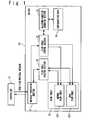
FIG. 1 , the open flow system of the present invention is provided with acontroller 10 and aswitch 20. - The
controller 10 forms one open flow system together with theswitch 20 and transmits and receives an open flow protocol message. - The
switch 20 is provided with amessage processing section 21, a flowtable control section 22, a platformfunction managing section 23,configuration data 24, a flow table 25 and a flowtable reading section 26. - The
message processing section 21 receives an open flow protocol message from thecontroller 10, analyzes the message, handles it by an appropriate one of inner modules ofswitch 20, assembles an open flow protocol message in response to a request from the one inner module and transmits it to thecontroller 10. - A flow modification (Flow Mod) message and a statistic request message exist as the open flow protocol messages. The flow modification (Flow Mod) message is a message for setting a flow entry to the flow table 25 of the switch 20 (addition, modification, deletion) or for generating the flow table 25. The statistic request message is a message for requesting statistic data of the flow entries, ports and the flow table 25 of the
switch 20. - The flow
table control section 22 inquires a confirmation of a flow received from themessage processing section 21 to the platformfunction managing section 23 and performs the addition, deletion and modification of the flow entry to the flow table 25 based on the inquiry result. - The platform
function managing section 23 determines whether or not the flow as an object is valid or invalid, in response to the inquiry from the flowtable control section 22. Here, the platformfunction managing section 23 refers to theconfiguration data 24 of theswitch 20 to confirm the network (NW) setting, when receiving the inquiry of the flow from the flowtable control section 22. That is, the platformfunction managing section 23 confirms whether or not a rule and an action of the flow as the object conform to theconfiguration data 24 of theswitch 20. - The
configuration data 24 is set in advance and is maintained or retained in theswitch 20. As an example of theconfiguration data 24, data of a node configuration in the network (NW) to which theswitch 20 belongs, data of functions which theswitch 20 has and so on are exemplified. - The flow table 25 has a normal flow table 251 and a save flow table 252.
- The normal flow table 251 is a flow table used to register a valid flow conforming to the
configuration data 24 of theswitch 20. - The save flow table 252 is a flow table used to register an invalid flow which does not conform to the
configuration data 24 of theswitch 20. - The flow
table reading section 26 generates a search key based on data of a header region of the flow received from themessage processing section 21, searches one flow entry in the flow table 25 based on the search key and reads the searched flow entry. - In this example, the
message processing section 21 receives a packet from the network, notifies a flow which is based on the packet, to the flowtable reading section 26, and transfers the flow according to a flow entry if there is the flow entry corresponding to the flow in the normal flow table 251. Also, themessage processing section 21 notifies the flow to thecontroller 10 if there is not any flow entry corresponding to the flow in the normal flow table 251. - At this time, it is desirable that a communication line for the
message processing section 21 to communicate with the network and a communication line for themessage processing section 21 to communicate with thecontroller 10 are different communication lines. However, actually, it is possible to use the same communication line. - As an example of the
controller 10, computers such as a PC (personal computer), an appliance (appliance), a work station, a mainframe, and a supercomputer are exemplified. Also, thecontroller 10 may be under a virtual machine (VM) environment built on a physical machine. - As an example of the
switch 20, a network switch is exemplified. The network switch may be an L3 switch (layer 3 switch), an L4 switch (layer 4 switch), an L7 switch/application switch (layer 7 switch) or a multi-layer switch and so on. Besides, as an example of theswitch 20, a router, a proxy, a gateway, a fire wall, a load balancer, a band control unit, a security monitoring and controlling unit, a base station, an access point, a computer which has a plurality of communication ports and so on are exemplified. - The
message processing section 21, the flowtable control section 22, the flowtable reading section 26, the platformfunction managing section 23 are realized by a hardware resource such as a processor driven by a program, a software resource such as a program to drive the hardware resource to execute a desired process, and a memory which stores the software resource and various kinds of data. The flow table 25 and theconfiguration data 24 are supposed to be stored in the above-mentioned memory. - As an example of the above-mentioned hardware resource, a CPU (Central Processing Unit), a microprocessor (microprocessor), a microcontroller, a semiconductor integrated circuit (IC) which has a function of an exclusive use, and so on are exemplified.
- As an example of the above-mentioned memory, a RAM (Random Access Memory), a ROM (Read Only Memory), semiconductor memory devices such as an EEPROM (Electrically Erasable and Programmable Read Only Memory) and a flash memory, secondary memories such as HDD (Hard Disk Drive) and SSD (Solid State Drive), or a removable disk, a storage medium (media) and so on for DVD (Digital Versatile Disk) and SD (Secure Digital) memory card and so on are exemplified. Also, the above-mentioned memory may be a storage unit which uses DAS (Direct Attached Storage), FC-SAN (Fibre Channel - Storage Area Network), NAS (Network Attached Storage), IP-SAN (IP - Storage Area Network), and so on.
- Also, the above-mentioned hardware resource and the above-mentioned memory may be unified. For example, in recent years, a 1-chip device such as a microcomputer is developed. Therefore, a case that the 1-chip microcomputer mounted on the
switch 20 is provided with a processor and a storage unit is exemplified. - However, actually, the present invention is not limited to these examples.
- The processing when setting a flow entry onto the flow table 25 will be described with reference to
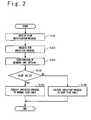
FIG. 2 . - The
message processing section 21 receives a flow modification (Flow Mod) message as an open flow protocol message from thecontroller 10. At this time, themessage processing section 21 may determine a type of the open flow protocol message received from thecontroller 10. - The
message processing section 21 requests the processing specified in the flow modification (Flow Mod) message to the flowtable control section 22 in response to the flow modification (Flow Mod) message. Here, the processing specified in the flow modification (Flow Mod) message is either of the addition, the deletion and the modification of the flow entry. - The flow
table control section 22 requests the confirmation of the network (NW) setting for the flow shown in the flow modification (Flow Mod) message to the platformfunction managing section 23. At this time, the flowtable control section 22 may start the platformfunction managing section 23. - The platform
function managing section 23 refers to theconfiguration data 24 of theswitch 20 to confirm the network (NW) setting, determines whether the flow is valid or invalid, and returns the confirmation result of the network (NW) setting (the determination result) to the flowtable control section 22. - The flow
table control section 22 performs the processing specified in the flow modification (Flow Mod) message (i.e. either of the addition, deletion and modification of the flow entry) to the normal flow table 251, when the flow is determined to be valid, as the confirmation result of the network (NW) setting. - The flow
table control section 22 performs the processing specified in the flow modification (Flow Mod) message (either of the addition, deletion and modification of the flow entry) to the save flow table 252, when the flow is determined to be invalid as the confirmation result of the network (NW) setting. - It should be noted that the flow
table control section 22 may instruct the deletion of the flow entry to both of the normal flow table 251 and the save flow table 252 sequentially or simultaneously without requesting the confirmation of the network (NW) setting to the platformfunction managing section 23, when the deletion of a flow entry is executed based on the flow received from themessage processing section 21. This is because the network (NW) setting is changed or modified after the flow entry is registered into either of the normal flow table 251 and the save flow table 252, so that there is a possibility that the confirmation results (the determination result) of the network (NW) setting are different between the time of the registration of the flow entry and the time of the deletion. - The processing when the flow notified from the
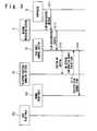
controller 10 conforms to theconfiguration data 24 of theswitch 20 and is registered on the normal flow table will be described with reference toFIG. 3 . - First, the
controller 10 transmits a flow modification (Flow Mod) message to themessage processing section 21 to instruct the registration of the flow. - The
message processing section 21 requests the flow registration to the flowtable control section 22 in response to the flow modification (Flow Mod) message. - The flow
table control section 22 requests the network (NW) setting confirmation to the platformfunction managing section 23 for the flow which is shown in the flow modification (Flow Mod) message. - The platform
function managing section 23 refers to theconfiguration data 24 of theswitch 20 to confirm the network (NW) setting, and returns the network (NW) setting confirmation result to the flowtable control section 22. Here, it is supposed that the network (NW) setting confirmation result shows that the flow is valid. - The flow
table control section 22 registers the flow entry to the flow on the normal flow table 251 when the flow is valid. - The processing that the flow notified from the
controller 10 and not conforming with theconfiguration data 24 of theswitch 20, is registered onto the save flow table will be described with reference toFIG. 4 . - First, the
controller 10 transmits the flow modification (Flow Mod) message to themessage processing section 21 to instruct the flow registration. - The
message processing section 21 requests the flow registration to the flowtable control section 22 in response to the flow modification (Flow Mod) message. - The flow
table control section 22 requests the confirmation of network (NW) setting to the platformfunction managing section 23 for the flow which is shown in the flow modification (Flow Mod) message. - The platform
function managing section 23 refers to theconfiguration data 24 of theswitch 20 to confirm the network (NW) setting, and returns the confirmation result of the network (NW) setting to the flowtable control section 22. Here, it is supposed that the confirmation result of the network (NW) setting shows that the flow is invalid. - The flow
table control section 22 registers the entry of the flow on the save flow table 252 when the flow is invalid. - The processing when a flow entry is read from the flow table 25 will be described with reference to
FIG. 5 . - The
message processing section 21 receives a statistic request (Statistics Request) message as one open flow protocol message from thecontroller 10. At this time, themessage processing section 21 may determine a type of the open flow protocol message received from thecontroller 10. - The
message processing section 21 requests a flow condition read for the flow which is shown in the statistic request message, to the flowtable reading section 26. Here, themessage processing section 21 notifies the flow to the flowtable reading section 26. At this time, themessage processing section 21 may start the flowtable reading section 26. - The flow
table reading section 26 confirms the flow condition in response to the flow condition read request. Here, the flowtable reading section 26 generates a search key based on the data of the header region of the flow, and searches the normal flow table 251 based on this search key to confirm the existence or non-existence of the corresponding flow entry in the normal flow table 251. - If there is a corresponding flow entry in the normal flow table 251, the flow
table reading section 26 confirms based on the flow condition confirmation result that there is the corresponding flow entry in the normal flow table 251. - If there is not the corresponding flow entry in the normal flow table 251, the flow
table reading section 26 confirms that there is not any corresponding flow entry in the normal flow table 251, from the flow condition confirmation result. - When there is not any corresponding flow entry in the normal flow table 251, the flow
table reading section 26 generates a search key based on the data of the header region of the flow, and searches the save flow table 252 based on this search key to confirm the existence or non-existence of the corresponding flow entry in the save flow table 252. - If there is any corresponding flow entry in the save flow table 252, the flow
table reading section 26 confirms that there is the corresponding flow entry in the save flow table 252, based on the flow condition confirmation result. - If there is not any corresponding flow entry in the save flow table 252, the flow
table reading section 26 confirms that there is not the corresponding flow entry in the save flow table 252, based on the flow condition confirmation result. In this case, it is proved that the flow is an unregistered flow which is registered on neither of the normal flow table 251 or the save flow table 252. - The flow
table reading section 26 notifies a flow condition reading result to themessage processing section 21 based on the flow condition confirmation result. For example, when there are a plurality of flows, the flowtable reading section 26 notifies the flow condition reading result to themessage processing section 21, after completing the flow condition confirmation to all of the flows. - The
message processing section 21 generates a statistical replying (Statistics Reply) message based on the flow condition reading result and transmits it to thecontroller 10. - The processing when the flow entry corresponding to the flow requested from the
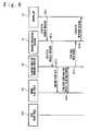
controller 10 is read from the normal flow table 251 will be described with reference toFIG. 6 . - First, the
controller 10 transmits a statistic request (Statistics Request) message to themessage processing section 21. - The
message processing section 21 issues a flow condition read request to the flowtable reading section 26 based on the flow which is contained or shown in the statistics request message. - The flow
table reading section 26 searches the normal flow table 251 based on the flow to confirm a flow condition of the existence or non-existence of the corresponding flow entry. Here, it is supposed that there is the corresponding flow entry in the normal flow table 251. - The flow
table reading section 26 confirms that there is the corresponding flow entry in the normal flow table 251, as the flow condition confirmation result. - After that, the flow
table reading section 26 notifies a flow condition reading result to themessage processing section 21. - The
message processing section 21 generates and transmits a statistics reply message to thecontroller 10. - The processing when the flow entry corresponding to the flow requested from the
controller 10 is read from the save flow table 252 will be described with reference toFIG. 7 . - First, the
controller 10 transmits a statistics request message to themessage processing section 21. - The
message processing section 21 issues a flow condition read request to the flowtable reading section 26 based on the flow which is shown in the statistics request message. - The flow
table reading section 26 searches the normal flow table 251 based on the flow to confirm a flow condition of the existence or non-existence of the corresponding flow entry. Here, it is supposed that there is not the corresponding flow entry in the normal flow table 251. - The flow
table reading section 26 confirms that there is not the corresponding flow entry in the normal flow table 251, as the flow condition confirmation result. - Next, the flow
table reading section 26 searches the save flow table 252 based on the flow to confirm a flow condition of the existence or non-existence of the corresponding flow entry. Here, it is supposed that there is the corresponding flow entry in the save flow table 252. - The flow
table reading section 26 confirms that there is the corresponding flow entry in the save flow table 252, as the flow condition confirmation result. - After that, the flow
table reading section 26 notifies the flow condition reading result to themessage processing section 21. - The
message processing section 21 generates and transmits a statistics reply message to thecontroller 10. - By this, the
controller 10 can confirm success or failure of the registration of a flow on the flow table 25, by only transmitting the statistics request message. - For example, after requesting the registration processing of a flow to the flow table 25 to the
switch 20, thecontroller 10 transmits the statistics request message of the flow to theswitch 20 in order to confirm whether or not the flow entry corresponding to the flow has succeeded in the registration on the flow table 25. Thecontroller 10 can confirm whether the registration of the flow entry onto the flow table 25 has succeeded or failed, by the statistics reply message from theswitch 20. - Next, the second exemplary embodiment of the present invention will be described.
- In the present exemplary embodiment, after the registration onto the flow table, whether or not the flow shown by the flow entry in the flow table is valid or invalid is reconfirmed.
- The processing of reconfirming whether the flow shown by the flow entry is valid or invalid will be described with reference to
FIG. 8 . - When the
configuration data 24 of theswitch 20 is modified, the platformfunction managing section 23 notifies it to the flowtable control section 22. When receiving the notice from the platformfunction managing section 23, the flowtable control section 22 notifies the received notice to themessage processing section 21. That is, when theconfiguration data 24 of theswitch 20 is modified or changed, the platformfunction managing section 23 notifies it to themessage processing section 21 directly or through the flowtable control section 22. - The
message processing section 21 requests the read of all the flow entries which are registered on the normal flow table 251 and the save flow table 252, to the flowtable reading section 26. - The flow
table reading section 26 reads all the flow entries which are registered on the normal flow table 251 and the save flow table 252 in response to the request from themessage processing section 21 and notifies to themessage processing section 21. It should be noted that actually, the flowtable reading section 26 may perform the reading operation of the flow entries in the normal flow table 251 and the reading operation of the flow entries in the save flow table 252 not collectively but separately (independently). In this case, the flowtable reading section 26 notifies the flow entries in the normal flow table 251 and the flow entries in the save flow table 252 to themessage processing section 21 separately. - The
message processing section 21 notifies all the flows shown by the flow entries which have notified from the flowtable reading section 26, to the flowtable control section 22. - The flow
table control section 22 requests the confirmation of the network (NW) setting for all the flows corresponding to the flow entries which have been notified from themessage processing section 21, to the platformfunction managing section 23. At this time, the flowtable control section 22 may start the platformfunction managing section 23. - The platform
function managing section 23 refers to theconfiguration data 24 of theswitch 20 to confirm the network (NW) setting, determines whether each flow is valid or invalid, and returns the network (NW) setting confirmation result (the determination result) to the flowtable control section 22. - If the object flow is a valid flow as the result of the network (NW) setting confirmation, the flow
table control section 22 executes the addition and modification of the flow entry to the normal flow table 251. - Moreover, if the object flow is one registered on the save flow table 252, the flow
table control section 22 deletes the flow entry from the save flow table 252. If the object flow is not the one registered on the save flow table 252, this operation is not performed. - Also, if the object flow is an invalid flow as the result of the network (NW) setting confirmation, the flow
table control section 22 performs the addition or modification of the flow entry to the save flow table 252. - Moreover, if the object flow is the one registered on the normal flow table 251, the flow
table control section 22 deletes the flow entry from the normal flow table 251. If the object flow is not the one registered on the normal flow table 251, this operation is not performed. - Here, it is supposed that it is known that the object flow is derived from which of the flow entry in the normal flow table 251 and the flow entry in the save flow table 252. For example, a case where the flow is related to data indicating that the flow is derived from or registered in which of flow tables is thought of. Or, a case where the processing to the flow entry in the normal flow table 251 and the processing to the flow entry in the save flow table 252 is performed separately (independent) is thought of.
- Also, even though it is not determined that the object flow is derived from either of the flow entry in the normal flow table 251 and the flow entry in the save flow table 252, the overlap registration can be avoided, if the already registered flow entries are deleted in advance before the object flow is re-registered on either of the normal flow table 251 and the save flow table 252. For example, the flow
table control section 22 generates a search key based on data of the header region of the object flow before the object flow is re-registered on the flow table after the flow is notified from themessage processing section 21, searches each flow table based on this search key, and deletes corresponding flow entry in advance. Or, not in units of flow entries but the existing flow tables 25 (the normal flow table 251 and the save flow table 252) may be initialized and deleted in advance, and the normal flow table 251 and the save flow table 252 may be newly generated in advance once more. - Moreover, the processing of the addition and modification of the flow entry of the registration object to the flow table may be performed unconditionally without determining that the object flow is derived from which of the flow entry in the normal flow table 251 and the flow entry in the save flow table 252, and otherwise, the processing of the deletion of the flow entry may be performed. Even if the flow entry corresponding to the object flow does not exist in the flow table to which the deletion processing of the flow entry has been performed, the deletion processing of the flow entry fails only.
- In this way, when a modification is applied to the
configuration data 24, theswitch 20 can reconfirm whether or not each of all the flow entries registered in the flow table 25 conforms to theconfiguration data 24, without receiving an instruction from thecontroller 10. - According to the present exemplary embodiment, the
controller 10 can automatically change or modify an invalid flow to a valid flow when theconfiguration data 24 is changed or modified by registering the invalid flow on the flow table 25 of theswitch 20 in advance. Thus, the flow table 25 of theswitch 20 can be made redundant. - Next, a third exemplary embodiment of the present invention will be described.
- In the present exemplary embodiment, reconfirmation processing of the validity of the flow entry is performed periodically or when a new flow is notified, as well as a case where a modification is applied to the
configuration data 24 of theswitch 20 in "the reconfirmation processing of the validity of the flow entry" shown in the second exemplary embodiment. - For example, the processing of the step S302 and the subsequent is performed at a predetermined time of every day or when receiving a flow modification (Flow Mod) message from the
controller 10, not when receiving a notice from the platformfunction managing section 23 at the step S301 shown inFIG. 8 . - According to the present exemplary embodiment, even if the modification of the
configuration data 24 is not detected, the modification of theconfiguration data 24 can be dealt. That is, the modification of theconfiguration data 24 is not detected immediately, and when reconfirming, the modification of theconfiguration data 24 is recognized ex post facto. - Next, a fourth exemplary embodiment of the present invention will be described.
- In the present exemplary embodiment, "the reconfirmation processing of the validity of the flow entry" shown in the second exemplary embodiment is performed immediately after "the read processing from the flow table" shown in the first exemplary embodiment.
- For example, processing of the step S305 and the subsequent shown in
FIG. 8 is performed immediately after the step S210 shown inFIG. 5 , or between the step S209 and the step S210. - Next, a fifth exemplary embodiment of the present invention will be described.
- In the present exemplary embodiment, "the reconfirmation processing of the validity of the flow entry" shown in the second exemplary embodiment may be performed by using the flow shown in the statistics request message as the object flow before starting a read from the flow table in "the read processing from the flow table" shown in the first exemplary embodiment.
- For example, the
message processing section 21 notifies to the flowtable control section 22 by using the flow shown in the statistics request message as the object flow between the step S201 and the step S202 shown inFIG. 5 . After that, the processing of the step S306 and the subsequent shown inFIG. 8 is performed. - In this case, the flow
table control section 22 does not know that the object flow is registered on which of the flow tables in the step S308 to the step S311. Therefore, the flowtable control section 22 generates a search key based on data in the header region of the object flow before re-registering the object flow in each flow table, searches each flow table by using the reference key, and deletes corresponding flow entry in advance. Or, the flowtable control section 22 performs the addition and modification of the flow entry corresponding to the object flow to the flow table of the registration object unconditionally and performs the deletion of the flow entry to the other flow table. - Next, a sixth exemplary embodiment of the present invention will be described.
- In the present exemplary embodiment, when a fault happens, the flow entry of the save table is made valid.
- For example, when the fault happens, the
message processing section 21 instructs the flowtable reading section 26 to read the flow entry of the save flow table 252 and receives a notice of the flow entry of the save flow table 252 from the flowtable reading section 26. Themessage processing section 21 instructs the flowtable control section 22 to perform the addition of the flow entry to the normal flow table 251 and the deletion of the flow entry from the save flow table 252 with respect to the flow shown in the flow entry. The flowtable control section 22 performs the addition of the flow entry to the normal flow table 251 and the deletion of the flow entry from the save flow table 252 in response to the instruction from themessage processing section 21. - It should be noted that because there is a case that a modification occurs in the
configuration data 24 of theswitch 20 when a fault occurs, a case where "the reconfirmation processing of the validity of the flow entry" in the second exemplary embodiment is dealt with is thought of. - It should be noted that the above-mentioned exemplary embodiments can be combined.
- As mentioned above, the present invention provides an open flow system using a save flow table.
- The switch in the open flow system of the present invention is to retain a flow entry which does not conform to a predetermined function as an invalid entry. The flow table which retains the invalid entry is referred to as a save flow table. That is, the switch in the open flow system of the present invention is provided with a normal flow table registered with a flow which conforms to the platform function of the switch, and the save flow table registered with a flow which does not conform to the platform function of the switch. Thus, the controller can confirm which flow entry is invalid, by using the statistics request (Statistics Request) message.
- The controller in the open flow system of the present invention can confirm flows succeeded and failed in the registration only by transmitting a statistics request (Statistics Request) message. Also, the controller can determine whether or not the flow to be registered on the flow table of the switch could be actually registered.
- Also, when a fault happens, it is possible to provide the open flow system with redundancy, by setting a flow entry in the save table to be valid.
- A part or all of the above-mentioned exemplary embodiments can be described like the following. However, the present invention is not limited to the following examples.
- A flow table control program includes: a step of confirming whether or not a flow notified from the controller conforms with a predetermined function to determine whether the flow is a valid flow or an invalid flow; a step of registering the valid flow on the normal flow table; a step of registering the invalid flow on the save flow table; and a step of recognizing a packet received from the network as the flow, and carrying out the processing specified to the flow to the packet when the flow is registered on the normal flow table.
- The flow table control program defined in Supplemental item 1, further includes: a step of reading a flow from either of the normal flow table and the save flow table in response to an inquiry of success or failure of flow registration from the controller; and a step of responding that the flow is registered on which of the normal flow table and the save flow table to the controller.
- The flow table control program defined in Supplemental item 1 or 2, further includes: a step of detecting a modification of the predetermined function; a step of confirming whether each of the flows registered on the normal flow table and the save flow table conforms with the predetermined function based on the modification of the predetermined function to determine whether or not each flow is a valid flow or an invalid flow; a step of registering the valid flow on the said normal flow table; a step of deleting from the save flow table when the valid flow is registered on the save flow table; a step of registering the invalid flow on the save flow table; and a step of deleting from the normal flow table when the invalid flow is registered on the normal flow table.
- As described above, the exemplary embodiments of the present invention have been described in detail. However, actually, the present invention is not limited to the above-mentioned exemplary embodiments and a modification in the range which does not deviate from the scope of the present invention is contained in the present invention.
Claims (8)
- A switch comprising:a platform function managing section (23) for confirming whether or not a flow notified from a controller (10) conforms to a predetermined function and determining whether or not the flow is valid or invalid;a flow table control section (22) for:registering a valid flow on a normal flow table (251) andregistering an invalid flow on a save flow table (252) such that flows not conforming to the predetermined function are retained; anda message processing section (21) for:recognizing a packet received from a network as a flow and performing processing specified for the flow on the packet when the flow has been registered in the normal flow table.
- The switch according to claim 1, further comprising:a flow table reading section (26) for reading the flow from either of the normal flow table (251) and the save flow table (252) in response to an inquiry of success or failure of flow registration from the controller (10); and whereinthe message processing section (21) responds that the flow is registered on which of the normal flow table and the save flow table, to the controller.
- The switch according to claim 1 or 2, wherein the platform function managing section (23):detects whether or not there is a modification of the predetermined function;confirms whether or not each of the flows registered on the normal flow table (251) and the save flow table (252) conform to the predetermined function, based on a modification of the predetermined function, and determines whether each flow is a valid flow or an invalid flow; andwherein the flow table control section (22) is capable of:deleting the valid flow from the save flow table when the valid flow has been registered on the save flow table, anddeleting the invalid flow from the normal flow table when the invalid flow has been registered on the normal flow table.
- The switch according to any of claims 1 to 3, wherein the message processing section (21) is capable of validating a flow which has been registered on the save flow table (252) when a fault occurs.
- A flow table controlling method for use in a switch (20), the method comprising the steps of:confirming whether or not a flow notified from a controller (10) conforms to a predetermined function to determine whether the notified flow is a valid flow or an invalid flow;registering the valid flow on a normal flow table (251);registering the invalid flow on a save flow table (252) such that flows not conforming to the predetermined function are retained; andrecognizing a packet received from a network as a flow and carrying out processing specified for the flow on the packet when the flow has been registered in the normal flow table.
- The flow table controlling method according to claim 5, further comprising:reading a flow from either of the normal flow table (251) and the save flow table (252) in response to an inquiry of success or failure of flow registration from the controller (10); andreplying which of the normal flow table and the save flow table the flow has been registered on, to the controller.
- The flow table controlling method according to claim 5 or 6, further comprising:detecting a modification of the predetermined function;confirming whether each of flows registered on the normal flow table (251) and the save flow table (252) conforms to the predetermined function based on the modification of the predetermined function and determining whether each flow is a valid flow or an invalid flow;deleting the valid flow from the save flow table when the valid flow has been registered on the save flow table; anddeleting the invalid flow from the normal flow table when the invalid flow has been registered on the normal flow table.
- A storage medium which stores a flow table control program to make a switch (20) execute the flow table controlling method according to any of claims 5 to 7.
Applications Claiming Priority (2)
| Application Number | Priority Date | Filing Date | Title |
|---|---|---|---|
| JP2010095760 | 2010-04-19 | ||
| PCT/JP2011/059086WO2011132568A1 (en) | 2010-04-19 | 2011-04-12 | Switch, and flow table control method |
Publications (3)
| Publication Number | Publication Date |
|---|---|
| EP2562970A1 EP2562970A1 (en) | 2013-02-27 |
| EP2562970A4 EP2562970A4 (en) | 2013-12-04 |
| EP2562970B1true EP2562970B1 (en) | 2015-01-07 |
Family
ID=44834092
Family Applications (1)
| Application Number | Title | Priority Date | Filing Date |
|---|---|---|---|
| EP11771903.9ANot-in-forceEP2562970B1 (en) | 2010-04-19 | 2011-04-12 | Switch, and flow table control method |
Country Status (7)
| Country | Link |
|---|---|
| US (1) | US8971342B2 (en) |
| EP (1) | EP2562970B1 (en) |
| JP (1) | JP5299856B2 (en) |
| KR (1) | KR101422381B1 (en) |
| CN (1) | CN102859952B (en) |
| TW (1) | TWI455532B (en) |
| WO (1) | WO2011132568A1 (en) |
Families Citing this family (79)
| Publication number | Priority date | Publication date | Assignee | Title |
|---|---|---|---|---|
| US9769016B2 (en) | 2010-06-07 | 2017-09-19 | Brocade Communications Systems, Inc. | Advanced link tracking for virtual cluster switching |
| US8867552B2 (en) | 2010-05-03 | 2014-10-21 | Brocade Communications Systems, Inc. | Virtual cluster switching |
| US9716672B2 (en) | 2010-05-28 | 2017-07-25 | Brocade Communications Systems, Inc. | Distributed configuration management for virtual cluster switching |
| US9270486B2 (en) | 2010-06-07 | 2016-02-23 | Brocade Communications Systems, Inc. | Name services for virtual cluster switching |
| US9806906B2 (en) | 2010-06-08 | 2017-10-31 | Brocade Communications Systems, Inc. | Flooding packets on a per-virtual-network basis |
| US9807031B2 (en) | 2010-07-16 | 2017-10-31 | Brocade Communications Systems, Inc. | System and method for network configuration |
| US9736085B2 (en) | 2011-08-29 | 2017-08-15 | Brocade Communications Systems, Inc. | End-to end lossless Ethernet in Ethernet fabric |
| JP6036816B2 (en)* | 2011-09-22 | 2016-11-30 | 日本電気株式会社 | Communication terminal, communication method, and program |
| US9450870B2 (en) | 2011-11-10 | 2016-09-20 | Brocade Communications Systems, Inc. | System and method for flow management in software-defined networks |
| US8644149B2 (en)* | 2011-11-22 | 2014-02-04 | Telefonaktiebolaget L M Ericsson (Publ) | Mechanism for packet forwarding using switch pools in flow-based, split-architecture networks |
| US8976661B2 (en)* | 2012-01-11 | 2015-03-10 | Nec Laboratories America, Inc. | Network self-protection |
| US8995272B2 (en) | 2012-01-26 | 2015-03-31 | Brocade Communication Systems, Inc. | Link aggregation in software-defined networks |
| US9742693B2 (en) | 2012-02-27 | 2017-08-22 | Brocade Communications Systems, Inc. | Dynamic service insertion in a fabric switch |
| US8705536B2 (en)* | 2012-03-05 | 2014-04-22 | Telefonaktiebolaget L M Ericsson (Publ) | Methods of operating forwarding elements including shadow tables and related forwarding elements |
| US9154416B2 (en) | 2012-03-22 | 2015-10-06 | Brocade Communications Systems, Inc. | Overlay tunnel in a fabric switch |
| EP2833582A4 (en)* | 2012-03-28 | 2015-12-02 | Nec Corp | Computer system and communication path modification means |
| US9184995B2 (en)* | 2012-04-11 | 2015-11-10 | Gigamon Inc. | Traffic visibility in an open networking environment |
| US9374301B2 (en) | 2012-05-18 | 2016-06-21 | Brocade Communications Systems, Inc. | Network feedback in software-defined networks |
| US10277464B2 (en) | 2012-05-22 | 2019-04-30 | Arris Enterprises Llc | Client auto-configuration in a multi-switch link aggregation |
| US20140040459A1 (en)* | 2012-08-01 | 2014-02-06 | Hewlett-Packard Development Company, L.P. | System and method for data communication using a classified flow table in openflow networks |
| CN102843299A (en)* | 2012-09-12 | 2012-12-26 | 盛科网络(苏州)有限公司 | Method and system for realizing Openflow multi-stage flow tables on basis of ternary content addressable memory (TCAM) |
| US9401872B2 (en) | 2012-11-16 | 2016-07-26 | Brocade Communications Systems, Inc. | Virtual link aggregations across multiple fabric switches |
| US9413691B2 (en) | 2013-01-11 | 2016-08-09 | Brocade Communications Systems, Inc. | MAC address synchronization in a fabric switch |
| US9548926B2 (en) | 2013-01-11 | 2017-01-17 | Brocade Communications Systems, Inc. | Multicast traffic load balancing over virtual link aggregation |
| CN104009930B (en)* | 2013-02-22 | 2017-09-22 | 上海贝尔股份有限公司 | The method and apparatus that SDN stream matchings are carried out based on implicit stream information |
| US9565099B2 (en) | 2013-03-01 | 2017-02-07 | Brocade Communications Systems, Inc. | Spanning tree in fabric switches |
| WO2014145750A1 (en) | 2013-03-15 | 2014-09-18 | Brocade Communications Systems, Inc. | Scalable gateways for a fabric switch |
| CN104079492B (en)* | 2013-03-28 | 2017-10-10 | 华为技术有限公司 | The methods, devices and systems that flow table is configured in a kind of OpenFlow networks |
| CN105519052B (en)* | 2013-05-09 | 2019-06-11 | 华为技术有限公司 | Packet forwarding method, device and system |
| TWI520530B (en)* | 2013-05-17 | 2016-02-01 | 智邦科技股份有限公司 | Packet switch device and method of the same |
| KR101404491B1 (en)* | 2013-06-05 | 2014-06-10 | 한국과학기술정보연구원 | System and Method for dynamic bandwidth setting of subnet based on OpenFlow network |
| US9699001B2 (en) | 2013-06-10 | 2017-07-04 | Brocade Communications Systems, Inc. | Scalable and segregated network virtualization |
| CN104641606B (en)* | 2013-06-13 | 2017-11-17 | 华为技术有限公司 | The method and virtual network management entity of Internet resources equilibrium treatment |
| WO2015027477A1 (en)* | 2013-08-30 | 2015-03-05 | 华为技术有限公司 | Flow table control method, apparatus, switch and controller |
| US9806949B2 (en) | 2013-09-06 | 2017-10-31 | Brocade Communications Systems, Inc. | Transparent interconnection of Ethernet fabric switches |
| CN104468357B (en)* | 2013-09-16 | 2019-07-12 | 中兴通讯股份有限公司 | Multipolarity method, the multilevel flow table processing method and processing device of flow table |
| US9912612B2 (en) | 2013-10-28 | 2018-03-06 | Brocade Communications Systems LLC | Extended ethernet fabric switches |
| CN104683243B (en)* | 2013-11-26 | 2019-02-01 | 华为技术有限公司 | A kind of data processing method, apparatus and system |
| EP3447977B1 (en) | 2013-12-11 | 2021-05-26 | Huawei Technologies Co., Ltd. | Packet processing method and apparatus |
| CN104754560B (en) | 2013-12-30 | 2018-11-30 | 华为终端(东莞)有限公司 | A kind of location privacy protection method, apparatus and system |
| WO2015109497A1 (en)* | 2014-01-23 | 2015-07-30 | 华为技术有限公司 | Flow table modifying method, flow table modifying device, and openflow network system |
| CN104811403B (en)* | 2014-01-27 | 2019-02-26 | 中兴通讯股份有限公司 | Open flow-based group table processing method, device and group table configuration unit |
| US9629018B2 (en) | 2014-02-05 | 2017-04-18 | Ibasis, Inc. | Method and apparatus for triggering management of communication flow in an inter-network system |
| US10263903B2 (en)* | 2014-02-05 | 2019-04-16 | Ibasis, Inc. | Method and apparatus for managing communication flow in an inter-network system |
| US9548873B2 (en) | 2014-02-10 | 2017-01-17 | Brocade Communications Systems, Inc. | Virtual extensible LAN tunnel keepalives |
| CN104869057B (en)* | 2014-02-21 | 2019-03-01 | 中兴通讯股份有限公司 | Open flow switch Graceful Restart processing method, device and open flow controller |
| US10581758B2 (en) | 2014-03-19 | 2020-03-03 | Avago Technologies International Sales Pte. Limited | Distributed hot standby links for vLAG |
| US10476698B2 (en) | 2014-03-20 | 2019-11-12 | Avago Technologies International Sales Pte. Limited | Redundent virtual link aggregation group |
| CN103957157B (en)* | 2014-03-25 | 2017-03-22 | 中国人民解放军国防科学技术大学 | Route method for network interface to define forwarding rule |
| WO2015143620A1 (en)* | 2014-03-25 | 2015-10-01 | 华为技术有限公司 | Data flow statistics collection method, system and apparatus |
| JP6287443B2 (en) | 2014-03-26 | 2018-03-07 | 富士通株式会社 | Control device and table creation method thereof |
| WO2015157935A1 (en)* | 2014-04-16 | 2015-10-22 | 华为技术有限公司 | Flow table entry management method and device |
| US10063473B2 (en) | 2014-04-30 | 2018-08-28 | Brocade Communications Systems LLC | Method and system for facilitating switch virtualization in a network of interconnected switches |
| US9800471B2 (en) | 2014-05-13 | 2017-10-24 | Brocade Communications Systems, Inc. | Network extension groups of global VLANs in a fabric switch |
| US9935831B1 (en)* | 2014-06-03 | 2018-04-03 | Big Switch Networks, Inc. | Systems and methods for controlling network switches using a switch modeling interface at a controller |
| US10616108B2 (en) | 2014-07-29 | 2020-04-07 | Avago Technologies International Sales Pte. Limited | Scalable MAC address virtualization |
| CN105684382A (en)* | 2014-08-11 | 2016-06-15 | 华为技术有限公司 | Packet control method, switch and controller |
| US9807007B2 (en) | 2014-08-11 | 2017-10-31 | Brocade Communications Systems, Inc. | Progressive MAC address learning |
| US9699029B2 (en) | 2014-10-10 | 2017-07-04 | Brocade Communications Systems, Inc. | Distributed configuration management in a switch group |
| CN104486119A (en)* | 2014-12-16 | 2015-04-01 | 盛科网络(苏州)有限公司 | Method and system for achieving batch management switch through improved openflow protocol |
| US9942097B2 (en) | 2015-01-05 | 2018-04-10 | Brocade Communications Systems LLC | Power management in a network of interconnected switches |
| US10003552B2 (en) | 2015-01-05 | 2018-06-19 | Brocade Communications Systems, Llc. | Distributed bidirectional forwarding detection protocol (D-BFD) for cluster of interconnected switches |
| US9467378B1 (en)* | 2015-03-01 | 2016-10-11 | Netronome Systems, Inc. | Method of generating subflow entries in an SDN switch |
| US10038592B2 (en) | 2015-03-17 | 2018-07-31 | Brocade Communications Systems LLC | Identifier assignment to a new switch in a switch group |
| US9807005B2 (en) | 2015-03-17 | 2017-10-31 | Brocade Communications Systems, Inc. | Multi-fabric manager |
| CN104821890A (en)* | 2015-03-27 | 2015-08-05 | 上海博达数据通信有限公司 | Realization method for OpenFlow multi-level flow tables based on ordinary switch chip |
| US10579406B2 (en) | 2015-04-08 | 2020-03-03 | Avago Technologies International Sales Pte. Limited | Dynamic orchestration of overlay tunnels |
| WO2017000235A1 (en)* | 2015-06-30 | 2017-01-05 | 华为技术有限公司 | Flow table ageing method, switch and controller |
| US9948518B2 (en)* | 2015-07-22 | 2018-04-17 | International Business Machines Corporation | Low latency flow cleanup of openflow configuration changes |
| US10439929B2 (en) | 2015-07-31 | 2019-10-08 | Avago Technologies International Sales Pte. Limited | Graceful recovery of a multicast-enabled switch |
| CN105591934B (en)* | 2015-08-05 | 2019-07-09 | 新华三技术有限公司 | A kind of management method and device of flow table |
| US10171303B2 (en) | 2015-09-16 | 2019-01-01 | Avago Technologies International Sales Pte. Limited | IP-based interconnection of switches with a logical chassis |
| US9912614B2 (en) | 2015-12-07 | 2018-03-06 | Brocade Communications Systems LLC | Interconnection of switches based on hierarchical overlay tunneling |
| US10979890B2 (en) | 2016-09-09 | 2021-04-13 | Ibasis, Inc. | Policy control framework |
| US10237090B2 (en) | 2016-10-28 | 2019-03-19 | Avago Technologies International Sales Pte. Limited | Rule-based network identifier mapping |
| WO2018183332A1 (en) | 2017-03-30 | 2018-10-04 | Ibasis, Inc. | Esim profile switching without sms |
| CN107547421A (en)* | 2017-05-24 | 2018-01-05 | 新华三技术有限公司 | Asynchronous communication method and device |
| US10524116B2 (en) | 2017-06-27 | 2019-12-31 | Ibasis, Inc. | Internet of things services architecture |
| CN115442292B (en)* | 2022-08-29 | 2023-10-03 | 中国联合网络通信集团有限公司 | Data flow table adjusting method, device, equipment and storage medium |
Family Cites Families (19)
| Publication number | Priority date | Publication date | Assignee | Title |
|---|---|---|---|---|
| US6650640B1 (en) | 1999-03-01 | 2003-11-18 | Sun Microsystems, Inc. | Method and apparatus for managing a network flow in a high performance network interface |
| US6851000B2 (en) | 2000-10-03 | 2005-02-01 | Broadcom Corporation | Switch having flow control management |
| US7076594B2 (en)* | 2000-12-22 | 2006-07-11 | Cisco Technology, Inc. | Apparatus and method for preventing one way connectivity loops in a computer network |
| US6654343B1 (en) | 2001-03-19 | 2003-11-25 | Turin Networks | Method and system for switch fabric flow control |
| JP3965283B2 (en)* | 2001-07-02 | 2007-08-29 | 株式会社日立製作所 | Packet transfer device with multiple types of packet control functions |
| US7028098B2 (en)* | 2001-07-20 | 2006-04-11 | Nokia, Inc. | Selective routing of data flows using a TCAM |
| CN1292567C (en) | 2002-06-22 | 2006-12-27 | 华为技术有限公司 | IP Ring Distributed Bandwidth Processing Method |
| JP3711965B2 (en) | 2002-07-18 | 2005-11-02 | 日本電気株式会社 | IP flow multi-stage hash device, IP flow multi-stage hash method, IP flow multi-stage hash program, and recording medium thereof |
| JP2004173136A (en)* | 2002-11-22 | 2004-06-17 | Fujitsu Ltd | Network management device |
| EP1503548A1 (en)* | 2003-08-01 | 2005-02-02 | fg microtec GmbH | Distributed Quality of Service Management System |
| US7164912B2 (en)* | 2004-01-07 | 2007-01-16 | Research In Motion Limited | Apparatus, and associated method, for facilitating selection by a mobile node of a network through which to communicate using a hierarchical selection process |
| JP2006254134A (en) | 2005-03-11 | 2006-09-21 | Alaxala Networks Corp | Communication statistic collection apparatus |
| US20080120286A1 (en)* | 2006-11-22 | 2008-05-22 | Dettinger Richard D | Method and system for performing a clean operation on a query result |
| JP4791347B2 (en) | 2006-12-29 | 2011-10-12 | 富士通株式会社 | Entry compression / decompression method and entry compression / decompression apparatus |
| JP2008177806A (en)* | 2007-01-18 | 2008-07-31 | Hitachi Communication Technologies Ltd | Packet switched network and fault completion device |
| JP2009049592A (en) | 2007-08-16 | 2009-03-05 | Nippon Telegr & Teleph Corp <Ntt> | IP flow measurement circuit and IP flow measurement method |
| EP2597816B1 (en) | 2007-09-26 | 2019-09-11 | Nicira Inc. | Network operating system for managing and securing networks |
| JP2009296230A (en) | 2008-06-04 | 2009-12-17 | Nec Corp | Transmission network, transmission apparatus, channel switching method and program for transmission network |
| JP4358892B1 (en) | 2008-10-16 | 2009-11-04 | エア・ウォーター株式会社 | Fluorination treatment method, fluorination treatment apparatus, and method of using fluorination treatment apparatus |
- 2011
- 2011-04-12CNCN201180019954.1Apatent/CN102859952B/ennot_activeExpired - Fee Related
- 2011-04-12KRKR1020127027346Apatent/KR101422381B1/ennot_activeExpired - Fee Related
- 2011-04-12USUS13/642,106patent/US8971342B2/ennot_activeExpired - Fee Related
- 2011-04-12WOPCT/JP2011/059086patent/WO2011132568A1/enactiveApplication Filing
- 2011-04-12EPEP11771903.9Apatent/EP2562970B1/ennot_activeNot-in-force
- 2011-04-12JPJP2012511619Apatent/JP5299856B2/ennot_activeExpired - Fee Related
- 2011-04-18TWTW100113390Apatent/TWI455532B/ennot_activeIP Right Cessation
Also Published As
| Publication number | Publication date |
|---|---|
| JPWO2011132568A1 (en) | 2013-07-18 |
| KR101422381B1 (en) | 2014-07-22 |
| US20130114615A1 (en) | 2013-05-09 |
| EP2562970A1 (en) | 2013-02-27 |
| EP2562970A4 (en) | 2013-12-04 |
| WO2011132568A1 (en) | 2011-10-27 |
| CN102859952A (en) | 2013-01-02 |
| KR20120139824A (en) | 2012-12-27 |
| TW201218692A (en) | 2012-05-01 |
| CN102859952B (en) | 2016-05-11 |
| TWI455532B (en) | 2014-10-01 |
| JP5299856B2 (en) | 2013-09-25 |
| US8971342B2 (en) | 2015-03-03 |
Similar Documents
| Publication | Publication Date | Title |
|---|---|---|
| EP2562970B1 (en) | Switch, and flow table control method | |
| RU2562438C2 (en) | Network system and network management method | |
| JP5660211B2 (en) | Communication path control system and communication path control method | |
| KR101501397B1 (en) | Network system, switch, and connection terminal detection method | |
| CN103444143B (en) | Network system and policy route configuration method | |
| US11165869B2 (en) | Method and apparatus for dynamic destination address control in a computer network | |
| KR101572771B1 (en) | System and methods for controlling network traffic through virtual switches | |
| JP2015511074A (en) | System and method for communication | |
| WO2013115177A1 (en) | Network system and topology management method | |
| JP5861772B2 (en) | Network appliance redundancy system, control device, network appliance redundancy method and program | |
| US20160012008A1 (en) | Communication system, control apparatus, communication method, and program | |
| US10931565B2 (en) | Multi-VRF and multi-service insertion on edge gateway virtual machines | |
| JP5668503B2 (en) | Hazardous site filtering system and filtering method | |
| JP2013115733A (en) | Network system and network control method | |
| HK1180495A (en) | Network system and network managing method |
Legal Events
| Date | Code | Title | Description |
|---|---|---|---|
| PUAI | Public reference made under article 153(3) epc to a published international application that has entered the european phase | Free format text:ORIGINAL CODE: 0009012 | |
| 17P | Request for examination filed | Effective date:20121019 | |
| AK | Designated contracting states | Kind code of ref document:A1 Designated state(s):AL AT BE BG CH CY CZ DE DK EE ES FI FR GB GR HR HU IE IS IT LI LT LU LV MC MK MT NL NO PL PT RO RS SE SI SK SM TR | |
| DAX | Request for extension of the european patent (deleted) | ||
| REG | Reference to a national code | Ref country code:DE Ref legal event code:R079 Ref document number:602011012965 Country of ref document:DE Free format text:PREVIOUS MAIN CLASS: H04L0012560000 Ipc:H04L0012700000 | |
| A4 | Supplementary search report drawn up and despatched | Effective date:20131107 | |
| RIC1 | Information provided on ipc code assigned before grant | Ipc:H04L 12/70 20130101AFI20131031BHEP | |
| GRAP | Despatch of communication of intention to grant a patent | Free format text:ORIGINAL CODE: EPIDOSNIGR1 | |
| INTG | Intention to grant announced | Effective date:20140718 | |
| GRAS | Grant fee paid | Free format text:ORIGINAL CODE: EPIDOSNIGR3 | |
| GRAA | (expected) grant | Free format text:ORIGINAL CODE: 0009210 | |
| AK | Designated contracting states | Kind code of ref document:B1 Designated state(s):AL AT BE BG CH CY CZ DE DK EE ES FI FR GB GR HR HU IE IS IT LI LT LU LV MC MK MT NL NO PL PT RO RS SE SI SK SM TR | |
| REG | Reference to a national code | Ref country code:GB Ref legal event code:FG4D | |
| REG | Reference to a national code | Ref country code:CH Ref legal event code:EP | |
| REG | Reference to a national code | Ref country code:IE Ref legal event code:FG4D | |
| REG | Reference to a national code | Ref country code:AT Ref legal event code:REF Ref document number:706412 Country of ref document:AT Kind code of ref document:T Effective date:20150215 | |
| REG | Reference to a national code | Ref country code:DE Ref legal event code:R096 Ref document number:602011012965 Country of ref document:DE Effective date:20150226 | |
| REG | Reference to a national code | Ref country code:NL Ref legal event code:VDEP Effective date:20150107 | |
| REG | Reference to a national code | Ref country code:AT Ref legal event code:MK05 Ref document number:706412 Country of ref document:AT Kind code of ref document:T Effective date:20150107 | |
| REG | Reference to a national code | Ref country code:LT Ref legal event code:MG4D | |
| PG25 | Lapsed in a contracting state [announced via postgrant information from national office to epo] | Ref country code:FI Free format text:LAPSE BECAUSE OF FAILURE TO SUBMIT A TRANSLATION OF THE DESCRIPTION OR TO PAY THE FEE WITHIN THE PRESCRIBED TIME-LIMIT Effective date:20150107 Ref country code:NO Free format text:LAPSE BECAUSE OF FAILURE TO SUBMIT A TRANSLATION OF THE DESCRIPTION OR TO PAY THE FEE WITHIN THE PRESCRIBED TIME-LIMIT Effective date:20150407 Ref country code:BG Free format text:LAPSE BECAUSE OF FAILURE TO SUBMIT A TRANSLATION OF THE DESCRIPTION OR TO PAY THE FEE WITHIN THE PRESCRIBED TIME-LIMIT Effective date:20150407 Ref country code:SE Free format text:LAPSE BECAUSE OF FAILURE TO SUBMIT A TRANSLATION OF THE DESCRIPTION OR TO PAY THE FEE WITHIN THE PRESCRIBED TIME-LIMIT Effective date:20150107 Ref country code:HR Free format text:LAPSE BECAUSE OF FAILURE TO SUBMIT A TRANSLATION OF THE DESCRIPTION OR TO PAY THE FEE WITHIN THE PRESCRIBED TIME-LIMIT Effective date:20150107 Ref country code:ES Free format text:LAPSE BECAUSE OF FAILURE TO SUBMIT A TRANSLATION OF THE DESCRIPTION OR TO PAY THE FEE WITHIN THE PRESCRIBED TIME-LIMIT Effective date:20150107 Ref country code:LT Free format text:LAPSE BECAUSE OF FAILURE TO SUBMIT A TRANSLATION OF THE DESCRIPTION OR TO PAY THE FEE WITHIN THE PRESCRIBED TIME-LIMIT Effective date:20150107 | |
| PG25 | Lapsed in a contracting state [announced via postgrant information from national office to epo] | Ref country code:NL Free format text:LAPSE BECAUSE OF FAILURE TO SUBMIT A TRANSLATION OF THE DESCRIPTION OR TO PAY THE FEE WITHIN THE PRESCRIBED TIME-LIMIT Effective date:20150107 Ref country code:GR Free format text:LAPSE BECAUSE OF FAILURE TO SUBMIT A TRANSLATION OF THE DESCRIPTION OR TO PAY THE FEE WITHIN THE PRESCRIBED TIME-LIMIT Effective date:20150408 Ref country code:AT Free format text:LAPSE BECAUSE OF FAILURE TO SUBMIT A TRANSLATION OF THE DESCRIPTION OR TO PAY THE FEE WITHIN THE PRESCRIBED TIME-LIMIT Effective date:20150107 Ref country code:RS Free format text:LAPSE BECAUSE OF FAILURE TO SUBMIT A TRANSLATION OF THE DESCRIPTION OR TO PAY THE FEE WITHIN THE PRESCRIBED TIME-LIMIT Effective date:20150107 Ref country code:PL Free format text:LAPSE BECAUSE OF FAILURE TO SUBMIT A TRANSLATION OF THE DESCRIPTION OR TO PAY THE FEE WITHIN THE PRESCRIBED TIME-LIMIT Effective date:20150107 Ref country code:LV Free format text:LAPSE BECAUSE OF FAILURE TO SUBMIT A TRANSLATION OF THE DESCRIPTION OR TO PAY THE FEE WITHIN THE PRESCRIBED TIME-LIMIT Effective date:20150107 Ref country code:IS Free format text:LAPSE BECAUSE OF FAILURE TO SUBMIT A TRANSLATION OF THE DESCRIPTION OR TO PAY THE FEE WITHIN THE PRESCRIBED TIME-LIMIT Effective date:20150507 | |
| REG | Reference to a national code | Ref country code:DE Ref legal event code:R097 Ref document number:602011012965 Country of ref document:DE | |
| PG25 | Lapsed in a contracting state [announced via postgrant information from national office to epo] | Ref country code:DK Free format text:LAPSE BECAUSE OF FAILURE TO SUBMIT A TRANSLATION OF THE DESCRIPTION OR TO PAY THE FEE WITHIN THE PRESCRIBED TIME-LIMIT Effective date:20150107 Ref country code:EE Free format text:LAPSE BECAUSE OF FAILURE TO SUBMIT A TRANSLATION OF THE DESCRIPTION OR TO PAY THE FEE WITHIN THE PRESCRIBED TIME-LIMIT Effective date:20150107 Ref country code:RO Free format text:LAPSE BECAUSE OF FAILURE TO SUBMIT A TRANSLATION OF THE DESCRIPTION OR TO PAY THE FEE WITHIN THE PRESCRIBED TIME-LIMIT Effective date:20150107 Ref country code:SK Free format text:LAPSE BECAUSE OF FAILURE TO SUBMIT A TRANSLATION OF THE DESCRIPTION OR TO PAY THE FEE WITHIN THE PRESCRIBED TIME-LIMIT Effective date:20150107 Ref country code:CZ Free format text:LAPSE BECAUSE OF FAILURE TO SUBMIT A TRANSLATION OF THE DESCRIPTION OR TO PAY THE FEE WITHIN THE PRESCRIBED TIME-LIMIT Effective date:20150107 | |
| PLBE | No opposition filed within time limit | Free format text:ORIGINAL CODE: 0009261 | |
| STAA | Information on the status of an ep patent application or granted ep patent | Free format text:STATUS: NO OPPOSITION FILED WITHIN TIME LIMIT | |
| PG25 | Lapsed in a contracting state [announced via postgrant information from national office to epo] | Ref country code:MC Free format text:LAPSE BECAUSE OF FAILURE TO SUBMIT A TRANSLATION OF THE DESCRIPTION OR TO PAY THE FEE WITHIN THE PRESCRIBED TIME-LIMIT Effective date:20150107 Ref country code:LU Free format text:LAPSE BECAUSE OF FAILURE TO SUBMIT A TRANSLATION OF THE DESCRIPTION OR TO PAY THE FEE WITHIN THE PRESCRIBED TIME-LIMIT Effective date:20150412 | |
| REG | Reference to a national code | Ref country code:CH Ref legal event code:PL | |
| 26N | No opposition filed | Effective date:20151008 | |
| PG25 | Lapsed in a contracting state [announced via postgrant information from national office to epo] | Ref country code:IT Free format text:LAPSE BECAUSE OF FAILURE TO SUBMIT A TRANSLATION OF THE DESCRIPTION OR TO PAY THE FEE WITHIN THE PRESCRIBED TIME-LIMIT Effective date:20150107 | |
| REG | Reference to a national code | Ref country code:IE Ref legal event code:MM4A | |
| PG25 | Lapsed in a contracting state [announced via postgrant information from national office to epo] | Ref country code:LI Free format text:LAPSE BECAUSE OF NON-PAYMENT OF DUE FEES Effective date:20150430 Ref country code:CH Free format text:LAPSE BECAUSE OF NON-PAYMENT OF DUE FEES Effective date:20150430 | |
| PG25 | Lapsed in a contracting state [announced via postgrant information from national office to epo] | Ref country code:SI Free format text:LAPSE BECAUSE OF FAILURE TO SUBMIT A TRANSLATION OF THE DESCRIPTION OR TO PAY THE FEE WITHIN THE PRESCRIBED TIME-LIMIT Effective date:20150107 | |
| REG | Reference to a national code | Ref country code:FR Ref legal event code:PLFP Year of fee payment:6 | |
| PG25 | Lapsed in a contracting state [announced via postgrant information from national office to epo] | Ref country code:IE Free format text:LAPSE BECAUSE OF NON-PAYMENT OF DUE FEES Effective date:20150412 | |
| PG25 | Lapsed in a contracting state [announced via postgrant information from national office to epo] | Ref country code:BE Free format text:LAPSE BECAUSE OF FAILURE TO SUBMIT A TRANSLATION OF THE DESCRIPTION OR TO PAY THE FEE WITHIN THE PRESCRIBED TIME-LIMIT Effective date:20150107 | |
| PG25 | Lapsed in a contracting state [announced via postgrant information from national office to epo] | Ref country code:MT Free format text:LAPSE BECAUSE OF FAILURE TO SUBMIT A TRANSLATION OF THE DESCRIPTION OR TO PAY THE FEE WITHIN THE PRESCRIBED TIME-LIMIT Effective date:20150107 | |
| REG | Reference to a national code | Ref country code:FR Ref legal event code:PLFP Year of fee payment:7 | |
| PG25 | Lapsed in a contracting state [announced via postgrant information from national office to epo] | Ref country code:HU Free format text:LAPSE BECAUSE OF FAILURE TO SUBMIT A TRANSLATION OF THE DESCRIPTION OR TO PAY THE FEE WITHIN THE PRESCRIBED TIME-LIMIT; INVALID AB INITIO Effective date:20110412 Ref country code:SM Free format text:LAPSE BECAUSE OF FAILURE TO SUBMIT A TRANSLATION OF THE DESCRIPTION OR TO PAY THE FEE WITHIN THE PRESCRIBED TIME-LIMIT Effective date:20150107 | |
| PG25 | Lapsed in a contracting state [announced via postgrant information from national office to epo] | Ref country code:CY Free format text:LAPSE BECAUSE OF FAILURE TO SUBMIT A TRANSLATION OF THE DESCRIPTION OR TO PAY THE FEE WITHIN THE PRESCRIBED TIME-LIMIT Effective date:20150107 | |
| PG25 | Lapsed in a contracting state [announced via postgrant information from national office to epo] | Ref country code:PT Free format text:LAPSE BECAUSE OF FAILURE TO SUBMIT A TRANSLATION OF THE DESCRIPTION OR TO PAY THE FEE WITHIN THE PRESCRIBED TIME-LIMIT Effective date:20150507 | |
| PG25 | Lapsed in a contracting state [announced via postgrant information from national office to epo] | Ref country code:TR Free format text:LAPSE BECAUSE OF FAILURE TO SUBMIT A TRANSLATION OF THE DESCRIPTION OR TO PAY THE FEE WITHIN THE PRESCRIBED TIME-LIMIT Effective date:20150107 | |
| REG | Reference to a national code | Ref country code:FR Ref legal event code:PLFP Year of fee payment:8 | |
| PGFP | Annual fee paid to national office [announced via postgrant information from national office to epo] | Ref country code:GB Payment date:20180329 Year of fee payment:8 | |
| PGFP | Annual fee paid to national office [announced via postgrant information from national office to epo] | Ref country code:FR Payment date:20180315 Year of fee payment:8 | |
| PG25 | Lapsed in a contracting state [announced via postgrant information from national office to epo] | Ref country code:MK Free format text:LAPSE BECAUSE OF FAILURE TO SUBMIT A TRANSLATION OF THE DESCRIPTION OR TO PAY THE FEE WITHIN THE PRESCRIBED TIME-LIMIT Effective date:20150107 | |
| PGFP | Annual fee paid to national office [announced via postgrant information from national office to epo] | Ref country code:DE Payment date:20180327 Year of fee payment:8 | |
| PG25 | Lapsed in a contracting state [announced via postgrant information from national office to epo] | Ref country code:AL Free format text:LAPSE BECAUSE OF FAILURE TO SUBMIT A TRANSLATION OF THE DESCRIPTION OR TO PAY THE FEE WITHIN THE PRESCRIBED TIME-LIMIT Effective date:20150107 | |
| REG | Reference to a national code | Ref country code:DE Ref legal event code:R119 Ref document number:602011012965 Country of ref document:DE | |
| GBPC | Gb: european patent ceased through non-payment of renewal fee | Effective date:20190412 | |
| PG25 | Lapsed in a contracting state [announced via postgrant information from national office to epo] | Ref country code:GB Free format text:LAPSE BECAUSE OF NON-PAYMENT OF DUE FEES Effective date:20190412 Ref country code:DE Free format text:LAPSE BECAUSE OF NON-PAYMENT OF DUE FEES Effective date:20191101 | |
| PG25 | Lapsed in a contracting state [announced via postgrant information from national office to epo] | Ref country code:FR Free format text:LAPSE BECAUSE OF NON-PAYMENT OF DUE FEES Effective date:20190430 |